From Science to Engineering Practice - Evolving a ... 2016 Fatigue Lecture Komoro… · From...
52
From Science to Engineering Practice - Evolving a Structural Integrity Framework ASTM 2016 Fatigue Lecture Jerzy Komorowski with David Hoeppner and Min Liao
Transcript of From Science to Engineering Practice - Evolving a ... 2016 Fatigue Lecture Komoro… · From...

From Science to Engineering Practice -
Evolving a Structural Integrity
Framework
ASTM 2016 Fatigue Lecture
Jerzy Komorowski
with David Hoeppner and Min Liao

2
To my HOListic Structural Integrity Process (HOLSIP)
co-conspirators

Content
• HOLSIP - why “conspiracy”?
• About NRC and our collaborators
• We are still learning the hard way
• Engineering and Science
• HOLSIP the framework
• Selected Applications
• Future – the unfinished business
3
HOLSIP – why ‘conspiracy’
“Conspiracy” – collaboration of boondoggle bunch`
• In early 2000’s word ‘holistic’ was associated with
alternative (not science based) medicine rather than with:
• Holistic = Emphasizing the importance of the whole
and the interdependence of its parts.
• USAF was no longer interested in funding the core members: U.
Utah (D. Hoeppner), APES Inc. (C. Brooks) and NRC (JPK and N.
Bellinger)
• 2002 The series of annual HOLSIP workshops was
launched = boondoggles
• 2016 – February 21-26 – 15th HOLSIP workshop was held
at Snowbird Utah.
5
NRC and collaborators

HOLSIP workshop attendees
• Australia, North America, Asia (Japan), Europe
• Air forces (5), Industry (OEM 4, MRO, other),
Airworthiness, Safety, RTO (5), University (6)
• Research, Technology Development, Product
Development, Sustainment (MRO),
7 HOLSIP 15 (2016)
Aircraft airframes and engines,
pipelines, civil structures
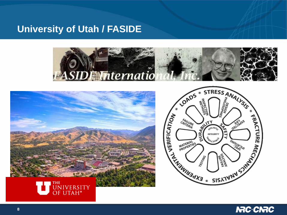
University of Utah / FASIDE
8

About NRC
• Approx. $900M budget
• 3,670 employees and 575 volunteer and independent visitors
• Industrial Research Assistance Program (IRAP) supports a variety
of disciplines and services in support of industry
• Research facilities provide strategic research & development and
technical services to national and international clients
9
IRAP
Research
facilities
Aerospace
research facilities

Facilities – $500M Research Infrastructure
10
Structures, Materials
and Manufacturing
Aerodynamics
Flight Research
Gas T
urb
ines

APES slide
11
We are still learning the hard way
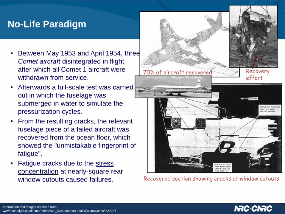
No-Life Paradigm
• Between May 1953 and April 1954, three
Comet aircraft disintegrated in flight,
after which all Comet 1 aircraft were
withdrawn from service.
• Afterwards a full-scale test was carried
out in which the fuselage was
submerged in water to simulate the
pressurization cycles.
• From the resulting cracks, the relevant
fuselage piece of a failed aircraft was
recovered from the ocean floor, which
showed the "unmistakable fingerprint of
fatigue".
• Fatigue cracks due to the stress
concentration at nearly-square rear
window cutouts caused failures.
Recovery effort
70% of aircraft recovered
Recovered section showing cracks at window cutouts
Information and images obtained from:
www.tech.plym.ac.uk/sme/Interactive_Resources/tutorials/FailureCases/sf2.html
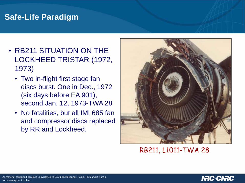
Safe-Life Paradigm
• RB211 SITUATION ON THE
LOCKHEED TRISTAR (1972,
1973)
• Two in-flight first stage fan
discs burst. One in Dec., 1972
(six days before EA 901),
second Jan. 12, 1973-TWA 28
• No fatalities, but all IMI 685 fan
and compressor discs replaced
by RR and Lockheed.
All material contained herein is Copyrighted to David W. Hoeppner, P.Eng., Ph.D and is from a forthcoming book by him.
RB211, L1011-TWA 28
Safe-Life Paradigm
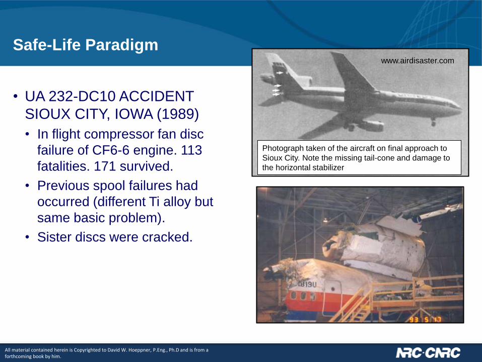
• UA 232-DC10 ACCIDENT
SIOUX CITY, IOWA (1989)
• In flight compressor fan disc
failure of CF6-6 engine. 113
fatalities. 171 survived.
• Previous spool failures had
occurred (different Ti alloy but
same basic problem).
• Sister discs were cracked.
Photograph taken of the aircraft on final approach to
Sioux City. Note the missing tail-cone and damage to
the horizontal stabilizer
www.airdisaster.com
All material contained herein is Copyrighted to David W. Hoeppner, P.Eng., Ph.D and is from a forthcoming book by him.

Damage Tolerance (Metals)
• ALOHA AIRLINES 243
ACCIDENT (1988)
• The aircraft lost 1/3 of its crown
due to a stress fracture while
cruising at 24,000 feet. 1 fatality.
© David W. Hoeppner – used by permission

Damage Tolerance (Metals)
• CAUSE OF SOUTHWEST
B733 NEAR YUMA (2011)
• MISALIGNED rivet holes where
two parts of the fuselage were
assembled.
• Wear-induced cracks
• Riveted joints that failed were
not extensively checked
because they were thought not
to be susceptible to fatigue.
Taken from various sources

• AIR TRANSAT AIRBUS A310
C-GPAT
• On 6th of March, 2005, over
international waters a rudder
detached from the vertical
stabilizer.
• Rudder is an all-composite
structure consisting of two
sandwich panels, hinge side spar,
top and bottom ribs.
• “No-Growth” design
Damage Tolerance
(Composites)

Engineering and Science
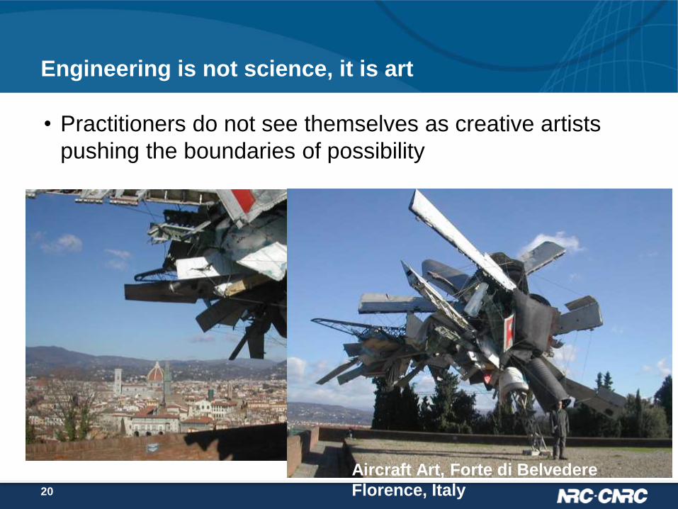
Engineering is not science, it is art
• Practitioners do not see themselves as creative artists
pushing the boundaries of possibility
Aircraft Art, Forte di Belvedere
Florence, Italy20
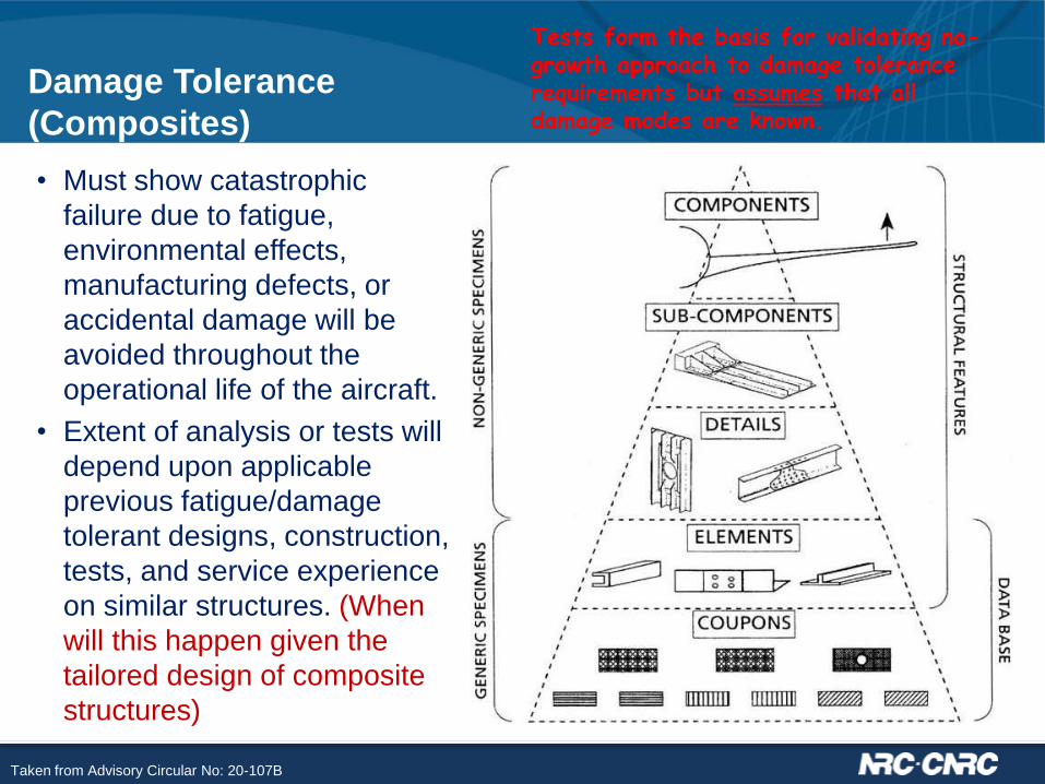
• Must show catastrophic
failure due to fatigue,
environmental effects,
manufacturing defects, or
accidental damage will be
avoided throughout the
operational life of the aircraft.
• Extent of analysis or tests will
depend upon applicable
previous fatigue/damage
tolerant designs, construction,
tests, and service experience
on similar structures. (When
will this happen given the
tailored design of composite
structures)
Damage Tolerance
(Composites)
Tests form the basis for validating no-growth approach to damage tolerance requirements but assumes that all damage modes are known.
Taken from Advisory Circular No: 20-107B
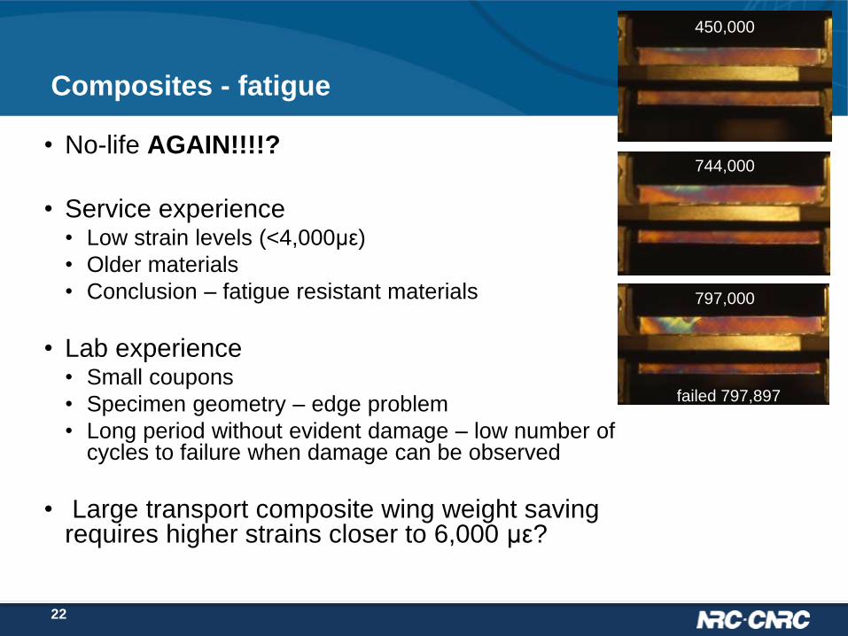
Composites - fatigue
• No-life AGAIN!!!!?
• Service experience • Low strain levels (<4,000με)
• Older materials
• Conclusion – fatigue resistant materials
• Lab experience• Small coupons
• Specimen geometry – edge problem
• Long period without evident damage – low number of cycles to failure when damage can be observed
• Large transport composite wing weight saving requires higher strains closer to 6,000 με?
450,000
744,000
797,000
failed 797,897
22

Composite Materials
• Physics based models (degradation, strength, failure) are
still needed and not yet available.
23

Metal fatigue more unfinished business
• Early stages not well modeled:
• dichotomy between Durability and DT
• EIFS problematic, post-diction
• “initiation” concept
• Environments not considered
Discontinuity
Heterogeneity
24

NRC Aerospace Aging Aircraft Specimen Library
25

Lap Joint Specimen Teardown
• Upper rivet row inner skin,
faying surface.
• Dark areas contain ~10%
thickness loss maximum.
• Cracks in the areas
adjacent to maximum
corrosion pillowing.
47-18A, Boeing 727-200 N4747, S4R - BS1020
X-ray images
26

Fatigue and Corrosion Pillowing
iiiiiiiv
0.065
inch
Intergranular
fracture
20 m
10 m
Fatigue striations
along crack front
Pillowing cracks found in 10
different a/c from 3
manufactures
27

Effect of Corrosion on Stress
• Finite element models generated with and without thickness loss.
• Results show strains significantly increase due to pillowing as compared to thickness loss effect.
0
1
2
3
4
5
6
7
8
10% material loss
s1 m
ax / s
1 r
em
ote
No
co
rro
sio
n
Th
ick
ne
ss
lo
ss
Pillo
win
g
Pillo
win
g +
thic
kn
ess l
oss
Corrosion simulation
R iv e t
O u te rS k in
In n e r S k in
Crack
28

HOLSIP the framework
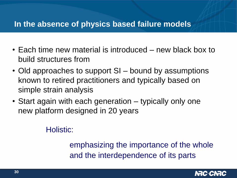
In the absence of physics based failure models
• Each time new material is introduced – new black box to
build structures from
• Old approaches to support SI – bound by assumptions
known to retired practitioners and typically based on
simple strain analysis
• Start again with each generation – typically only one
new platform designed in 20 years
Holistic:
emphasizing the importance of the whole
and the interdependence of its parts
30

P1:
Nucleation
P2: Short
Crack
P3: Long
Crack
P4:
Instability
Holistic life (with all intrinsic/extrinsic factors)
As-manufactured, IDS
Crack/corrosion
/fretting nucleation
Non-continuum mech.
Durability
Non-detectable
…
Short cracks
Damage interaction
EPFM/LEFM
Damage tolerant
Special NDI
…
MSD interaction
LEFM
NDI detectable
Repairable
…
Fract. toughness
Residual strength
WFD/MSD
LEFM/EPFM
…
Damage tolerant life
Holistic structural integrity Process (HOLSIP)
HOLSIP framework: to currently augment safe-life and damage tolerant
paradigms with the ultimate goal to evolve HOLSIP into a new paradigm
for both design and sustainment engineering
Key elements: physics & probabilistic models, loads monitoring,
environmental effects, advanced NDE/SHM, and risk assessment.
Developers: NRC, APES, U. Utah, Tri/Austin, AFRL/USAF, JAXA …
Safe Life (no env.) Damage Tolerant (no env.)
31

32
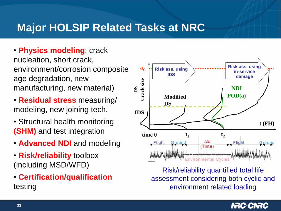
Holistic structural integrity Process (HOLSIP)
*HOLSIP terminology
Precise communication
DS
Cra
ck s
ize
t (FH)
t1 t2
IDS
Modified
DS
aC
NDI
POD(a)
time 0
Risk ass. using in-service damage
Risk ass. using
IDS
Risk/reliability quantified total life
assessment considering both cyclic and
environment related loading
• Physics modeling: crack
nucleation, short crack,
environment/corrosion composite
age degradation, new
manufacturing, new material)
• Residual stress measuring/
modeling, new joining tech.
• Structural health monitoring
(SHM) and test integration
• Advanced NDI and modeling
• Risk/reliability toolbox
(including MSD/WFD)
• Certification/qualification
testing
Major HOLSIP Related Tasks at NRC
33

#1 a
#1 b
#2 #3#4
IDS examples: particles, pores,
machining marks/scratches
Initial Discontinuity States (IDS): Initial population of
discontinuities that are in a structure made of a given
material as it was manufactured in a given geometric form
2024-T3 bareoverall
subset
IDS fatigue subset measured from
fracture surfaces
Initial Discontinuity States (Material Characterization)

Model and test results for crack-nucleating particle (area) for 7050
Extreme value model: IDS fatigue subset is in the right tail of the
overall IDS distribution, which can be determined using the extreme
value theory in the highest (95%) stress region, ex. Lognormal (overall
IDS) Frechet (IDS subset).
Correlation between overall IDS distribution and its
fatigue subsets
2
S (Z) T (Y)
L (X)
s
ss
)ln(2
])ln(22
)4ln()ln(ln([)ln(2exp[
0,,0],)(exp[)(
S
S
SS
b
S
Nb
N
NNa
baxx
axF

IDS Study for New Material 7249-T76511
Microstructural analysis: IDS (initial discontinuity states) study
• The analysis showed that the 7249 alloy has finer microstructures, especially
smaller particles, compared to the legacy 7075-T6 material (from a previous CFSD),
providing some physics for explaining the near-threshold FCGR difference between
these two materials
a) L-T plane b) S-T plane
L
T
T
S
36

0.00
0.05
0.10
0.15
0.20
0.25
0.30
0.35
0.40
0.45
0.50
0 100,000 200,000 300,000 400,000 500,000
Number of cycles
a=
L/2
(m
m)
(ha
lf s
urf
ace
cra
ck le
ng
th)
Monte Carlo (20/1000) MC average
AGARD R0,110MPa
a – N results for 2024-T351(SENT)
Analysis (a0: IDS/particle) vs. Test (AGARD 1982)
Probabilistic Short Crack Modeling (CTOD based)

Quantify Residual Stress Effect on Crack
Growth using ACR Technique
• The adjusted compliance ratio (ACR), developed by K. Donald, is an
experimental method for estimating ΔKeff .
• The ACR method intends to measure the crack closure effect below the 2%
crack-opening load, and quantify the remote closure effect induced by
residual stress (from forging or welding)
Source: K. Donald, What is ACR?
FCGR in 3.5%
NaCl immersion

39
Record of Airworthiness Risk Management
(RARM, RCAF, 2003)
Quantitative vs. Qualitative risk index
TAM, C-05-005-001/AG-001,
DTAES/DND, 2001
TAM, C-05-005-001/AG-001,
DTAES/DND, 2001
TAM, C-05-005-001/AG-001,
DTAES/DND, 2001
39
• Hazard Id.Risk Ass.(RA)Risk Ctrl.RARM ApprovalRisk Tracking
• Affecting all RCAF air fleets (DND-AD-2007-01)

Residual stress
testing/analysis
Physics of failure
(composite failure
library)
Usage/load
monitoring
Structural
analysis
Repair
technology
Advanced
NDI/POD
Structural
health/damage
monitoring
Physics based modeling with env’t
factors (temp. moisture…)
Material characterization &
processing variability
Risk/reliability Based Lifing Tech.
Structural integrity is the condition which exists when a structure is sound and
unimpaired in providing the desired level of structural safety, performance, durability,
and supportability (MIL-STD-1530/USAF ASIP)
Holistic Structural Integrity Process (HOLSIP)
for Composites/Hybrids

HOLSIP 15 NRC Progress Report - Feb 2016
41

Selected Applications

Fatigue life comparison between corroded and non-corroded longeron
2932 simulated flight hours in full scale test
0.0
0.2
0.4
0.6
0.8
1.0
1.2
1.4
1.6
1.8
2.0
0 2000 4000 6000 8000 10000 12000 14000 16000 18000
Simulated Flight Hours (SFH)C
rack L
en
gth
(in
ch
)
Non-corroded a-t data (FT 55 by Bombardier)
Non-corroded a-t curve byAFGROW (IDS=0.0071)
Instability
Corroded a-t data (FT245 by IAR/NRC)
Corroded a-t curve by ECLIPSE (IDS=0.0071)
Instability
(1984) (1994)
crack
cracknucleation site
blended outcorrosion
around fastener
Corrosion Fatigue Holistic Analysis
for F-18 Longeron
DDT analyses do not generally include
possibility of change of criticality of structure –
from durability to DT driven.
Corrosion can have such impact.side view of longeron at crack
nucleation site by replica
crackcorrosion pits
43

Advanced Damage Tolerant and Risk Analysis Tools
Developed under HOLSIP Framework
44
• NRC developed
advanced DTA and
risk analysis tools
(CanGROW,
ProDTA) under
HOLSIP framework
• NRC tools
provided significant
support to risk-based
management for
various RCAF
aircraft fleets
Risk analysis to determine the service life
limit of CC-130 center wing with MSD/MED(Liao, Renaud, Bombardier ICAF2015)
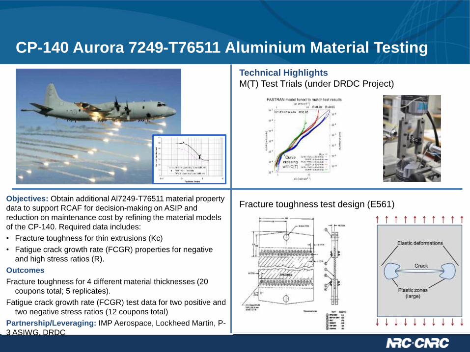
Objectives: Obtain additional Al7249-T76511 material property
data to support RCAF for decision-making on ASIP and
reduction on maintenance cost by refining the material models
of the CP-140. Required data includes:
• Fracture toughness for thin extrusions (Kc)
• Fatigue crack growth rate (FCGR) properties for negative
and high stress ratios (R).
Outcomes
Fracture toughness for 4 different material thicknesses (20
coupons total; 5 replicates).
Fatigue crack growth rate (FCGR) test data for two positive and
two negative stress ratios (12 coupons total)
Partnership/Leveraging: IMP Aerospace, Lockheed Martin, P-
3 ASIWG, DRDC
CP-140 Aurora 7249-T76511 Aluminium Material Testing
Technical Highlights
M(T) Test Trials (under DRDC Project)
Fracture toughness test design (E561)

Validation and Transfer of Cold-Work (CW) Modeling
Technology (FY15-16)
Objective:
Improve and validate methods/tools to determine practical Cold
Work (CW) Life Improvement Factors (LIF) using 2D and 3D
simulation, and residual stress database.
Background:
NRC and IMP recently completed cold worked hole tests for two
locations of the new 7249 Al CP-140 wing (ASLEP). The LIFs
determined in the lab (ideal conditions) need to be reduced to
reflect in-service experience and conditions.
Partnership/Leveraging: IMP, P-3 ASIWG, USN, USAF, RMC
Technical Highlights
• Brief Review of RCAF, USN, and USAF Practice
• USAF Residual Stress Database Investigation
• NRC Cold Expansion Simulation (3D FE)
• NRC Crack Growth Simulation, evaluating CPAT and BAMF
Crack growth rate at the crack nucleated from the unnotched side of the hole (#14-4)
1.0E-06
1.0E-05
150 200
dY
/d
N (
m/
cycl
e)
Crack size (Y) (m)
Distance from
the surface (Y)
The crack growth rates were calculated by assuming
that each marker band corresponded to a spectrum
pass (644,977 cycles)

4
7
Additive Repair Technology Development Program
– Cold Spray
Milestones
1. Evaluation of sprayed material strengths vs requirements
2. Selection of suitable repair alloy for 7075 forgings
3. Development and initial test of a repair process
4. Exposure and durability testing of repair components
5. Completion of the test program
6. Delivery of repair scheme
Deliverables / Outputs
1. Repair material compatibility report
2. Program tests report
3. Additive repair scheme for 7075 forgings.
Technical Highlights
Sprayed density looks promising for 7075
Property testing to commence early Feb
Objective:
The objective of this project is to develop an additive material
(Cold Spray) repair capability for the Canadian Forces.
The research focus is the restoration of parts reworked
(blended) beyond current repair limits.
Background:
Cold Spray is a metal spray process typically used to deposit
a sacrificial layer of metal on a component for corrosion
protection. Recent developments such as hand held kits,
improved materials and processes has opened the
possibility of using this technology for structural repair on
aircraft.
Impact/Benefit/Return on Investment:
The impact is significant. Additive manufacturing processes
have the potential to eliminate the costly replacement of
frames and fittings, such as the CH124 Sponsor
attachment fitting and the CH149 Main landing gear
frames. Potential savings are likely to exceed several
million dollars

Discussion Paper on Certification of Additive
Manufactured (AM) Components
Milestones
1. Review, gather information, draft report 03/16
2. Update draft paper with DND and TTCP data 11/16
Deliverables/Outputs
• Preliminary draft of discussion paper on Mar-16
• Final report on Nov-16
Technical Highlights
TTCP presentation and Draft report discussing
• major concerns/issues
• recommendation on R&D
Client(s): DND, DTAES 7-2
Sponsor(s): DTAES 7-2
Notes/Comments:
Technical Tasks
1. Identify possible certification issues relating to additive
manufactured components, such as quality, repeatability
and residual stresses.
2. Support TTCP AER TP4, SA 4B.5, and coordinate with
TTCP AER TP-4, MAT TP-1 and MAT TP-5
Objective: To prepare a discussion paper on certification of
additive manufactured (AM) components. This paper will
highlight the concerns relating to AM and the possible
solutions that will allow these manufactured parts to be
certified.
Background: AM is one of the most important technology
trends in aerospace and defence. However, there are
many issues/challenges for applying AM on primary aircraft
structures/critical parts, one of them is the quantification
and certification..
Impact/Benefit: Discussion paper documenting the major
issues/concerns relating to the certification of AM
components
Return on Investment: Increase fleet availability, reduce
maintenance cost.
FA-18 engine mount
bracket repair
Sea King tail wheel
support lug repair
RR501 fuel nozzle repair

Future – the unfinished business

Quo Vadimus?
• Concern – new generation of practitioners (OEMs) do not seem to participate in information exchanges as the previous generation did.
• “This is a secret” and “We are the best!” – syndrome?
• So much yet to be learned.
• Capture and share – open “learning" systems needed.
• Importance of standards and definitions.
• Will this ‘SI business’ ever be finished?
50

Black Swan
• Do we understand the risks?
51

Thank you
52