From AST to Code Generation Professor Yihjia Tsai Tamkang University.
34
From AST to Code Generation Professor Yihjia Tsai Tamkang University
-
Upload
lorraine-marshall -
Category
Documents
-
view
223 -
download
1
Transcript of From AST to Code Generation Professor Yihjia Tsai Tamkang University.

From AST to Code Generation
Professor Yihjia TsaiTamkang University
Summary of lecture 8
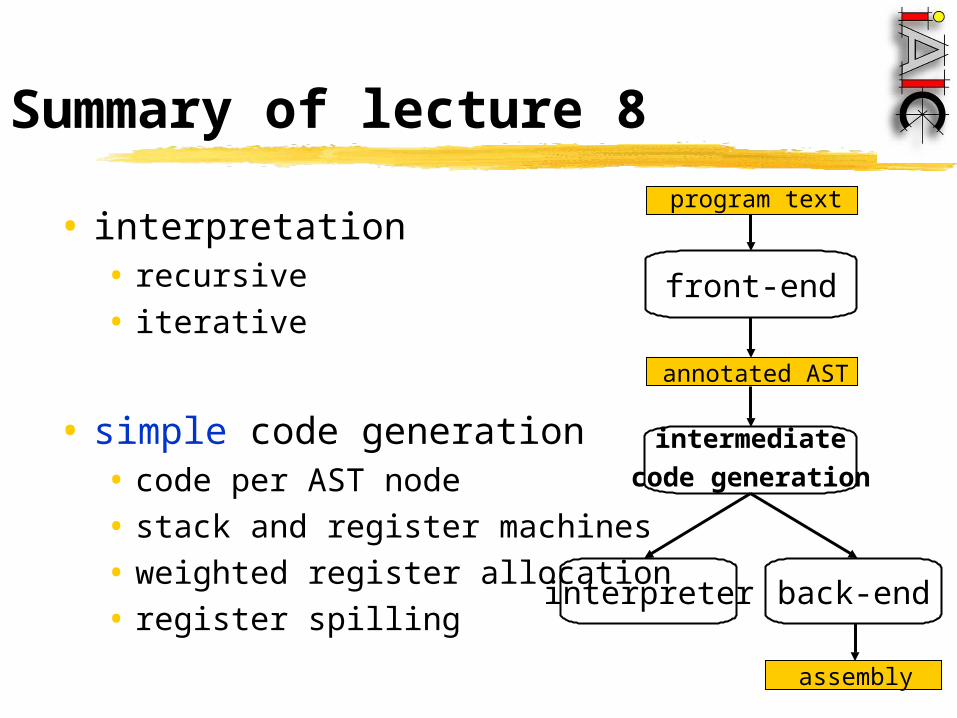
• interpretation• recursive• iterative
• simple code generation• code per AST node• stack and register machines• weighted register allocation• register spilling
program text
annotated AST
front-end
assembly
back-endinterpreter
intermediate
code generation

Quiz
4.7 Can the weight of a tree can also be used to reduce the maximum stack height when generating code for a stack machine? If not, why?If yes, how?

Overview
• code generation for basic blocks • [instruction selection: BURS]• register allocation: graph coloring• instruction ordering: ladder sequences
annotated AST
assembly
code generator
assembler
object file
linker
executable
library

Code generation forbasic blocks
• improve quality of code emitted by simple code generation
• consider multiple AST nodes at a time
•generate code for maximal basic blocks that cannot be extended by including adjacent AST nodes
basic block: a part of the control graph that
contains no splits (jumps) or combines (labels)
Code generation forbasic blocks
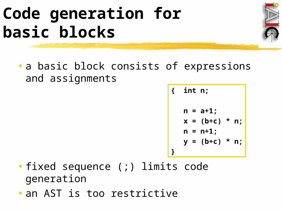
•a basic block consists of expressions and assignments
•fixed sequence (;) limits code generation•an AST is too restrictive
{ int n;
n = a+1;
x = (b+c) * n;
n = n+1;
y = (b+c) * n;
}

Example AST
+ n
=:
a 1 + n
* x
=:
b c
+ n
=:
n 1 + n
* y
=:
b c
; ; ;
{ int n;
n = a+1;
x = (b+c) * n;
n = n+1;
y = (b+c) * n;
}
Dependency graph
• convert AST to a directed acyclic graph (dag) capturing essential data dependencies
•data flow inside expressions: operands must be evaluated before operator is
applied
•data flow from a value assigned to variable V to the use of V: the usage of V is not affected by other
assignments

AST to dependency graph
• replace arcs by downwards arrows (upwards for destination under assignment)
• insert data dependencies from use of V to preceding assignment to V
• insert data dependencies between consecutive assignments to V
• add roots to the graph (output variables)• remove ;-nodes and connecting arrows
AST
dependency graph

+
b c a
+
1
*
x
+ +
1
*
y
Example dependency graph
{ int n;
n = a+1;
x = (b+c) * n;
n = n+1;
y = (b+c) * n;
}

+
b c a
+
1
*
x
+ +
1
*
y
Common subexpression elimination
• common subexpressions occur multiple times and evaluate to the same value
{ int n;
n = a+1;
x = (b+c) * n;
n = n+1;
y = (b+c) * n;
}
+
b c a
+
1
*
x
+
1
*
y

Exercise (7 min.)
•given the code fragment
draw the dependency graph before and after common subexpression elimination.
x := a*a + 2*a*b + b*b;
y := a*a – 2*a*b + b*b;

Answers

Answers
dependency graph before CSE
*
a a *
2 a
*
b
+ *
b b
+
x
*
a a *
2 a
*
b
- *
b b
+
y

Answers
dependency graph after CSE
*
2
*
+
+
x
*
a
*
b *
a a *
2 a
*
b
- *
b b
+
y

Answers
dependency graph after CSE
*
2
*
+
+
x
-
+
y
*
a
*
b
From dependency graphto code
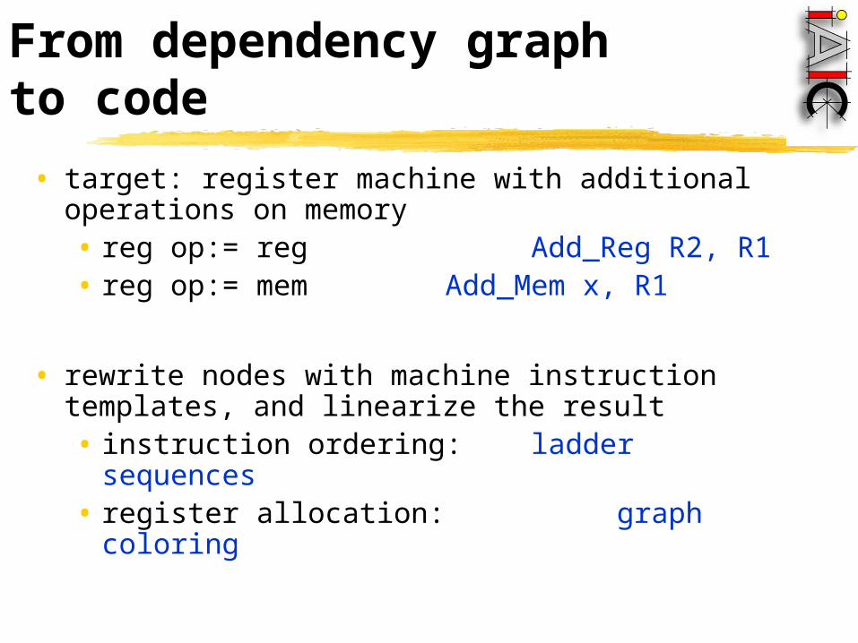
• target: register machine with additional operations on memory• reg op:= reg Add_Reg R2, R1• reg op:= mem Add_Mem x, R1
• rewrite nodes with machine instruction templates, and linearize the result• instruction ordering: ladder sequences• register allocation: graph coloring

Linearization of thedata dependency graph
• example:
(a+b)*c – d
• definition of a ladder sequence• each root node is a ladder sequence • a ladder sequence S ending in operator node N
can be extended with the left operand of N• if operator N is communitative then S may also
extended with the right operand of N
Load_Mem a, R1
Add_Mem b, R1
Mul_Mem, c, R1
Sub_Mem d, R1

• code generation for a ladder sequence
+
b c
*
x
a
+
1
+
1
*
y
+
b c
*
x
Linearization of thedata dependency graph

RT
Linearization of thedata dependency graph
• code generation for a ladder sequence
• instructions from bottom to top, one register
+
b c
*
xStore_Mem R1, x
+
b c
*
x
RT RT
Mul_Reg RT, R1
RTAdd_Mem c, R1
Load_Mem b, R1
Linearization of thedata dependency graph
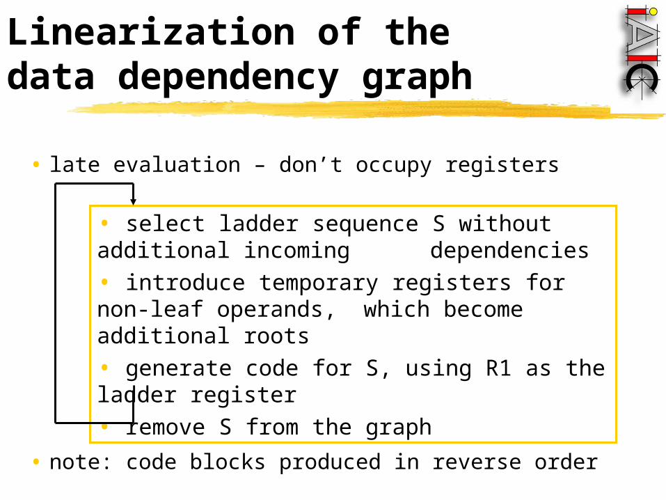
• late evaluation – don’t occupy registers
• note: code blocks produced in reverse order
• select ladder sequence S without additional incoming dependencies• introduce temporary registers for non-leaf operands, which become additional roots• generate code for S, using R1 as the ladder register• remove S from the graph

Examplecode generation
Load_Const 1, R1
Add_Reg R3, R1
Mul_Reg, R2, R1
Store_Mem R1, y
1) ladder: y, *, +
Load_Reg R2, R1
Mul_Reg R3, R1
Store_Mem R1, x
2) ladder: x, *
Load_Mem b, R1
Add_Mem c, R1
Load_Reg R1, R2
3) ladder: R2, +
Load_Const 1, R1
Add_Mem c, R1
Load_Reg R1, R3
4) ladder: R3, +
R2 R3
+
b c a
+
1
*
x
+
1
*
y

Exercise (7 min.)
•generate code for the following dependency graph
*
2
*
+
+
x
-
+
y
*
a
*
b
Answers

Answers
*
2
*
+
+
x
-
+
y
*
a
*
b
Load_Reg R2, R1
Add_Reg R3, R1
Add_Reg, R4, R1
Store_Mem R1, x
1) ladder: x, +, +
Load_Reg R2, R1
Sub_Reg R3, R1
Add_Reg, R4, R1
Store_Mem R1, y
2) ladder: y, +, -
R2R3
R4
Load_Const 2, R1
Mul_Reg Ra, R1
Mul_Reg, Rb, R1
Load_Reg R1, R3
3) ladder: R3, *, *
Load_Reg Ra, R1
Mul_Reg Ra, R1
Load_Reg R1, R2
4) ladder: R2, *
Load_Reg Rb, R1
Mul_Reg Rb, R1
Load_Reg R1, R4
5) ladder: R4, *

Register allocation by graph coloring
• procedure-wide register allocation• only live variables require register storage
• two variables(values) interfere when their live ranges overlap
dataflow analysis: a variable is live at node N if the value it holds is used on some path further down the control-flow graph; otherwise it is dead
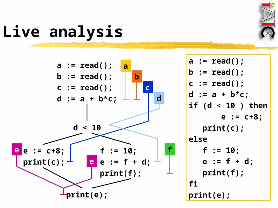
Live analysis
a := read();
b := read();
c := read();
d := a + b*c;
d < 10
e := c+8;
print(c);
f := 10;
e := f + d;
print(f);
print(e);
f
c
e
e
ab
d
a := read();
b := read();
c := read();
d := a + b*c;
if (d < 10 ) then
e := c+8;
print(c);
else
f := 10;
e := f + d;
print(f);
fi
print(e);

Register interference graph
a b
e
dc
f
a := read();
b := read();
c := read();
d := a + b*c;
d < 10
e := c+8;
print(c);
f := 10;
e := f + d;
print(f);
print(e);
f
c
e
e
ab
d

Graph coloring
• NP complete problem
• heuristic: color easy nodes last• find node N with lowest degree• remove N from the graph• color the simplified graph • set color of N to the first color that is
not used by any of N’s neighbors
a b
e
dc
f

Exercise (7 min.)
given that a and b are live on entry and dead on exit,and that x and y are live on exit: (a) construct the register interference graph (b) color the graph; how many register are needed?
{ int tmp_2ab = 2*a*b;
int tmp_aa = a*a;
int tmp_bb = b*b;
x := tmp_aa + tmp_2ab + tmp_bb;
y := tmp_aa - tmp_2ab + tmp_bb;
}

Answers

Answers
4 registers are needed
a tmp_2ab
tmp_bb
x y
tmp_aab

Code optimization
• preprocessing• constant folding a[1] *(a+4*1) *(a+4) • strength reduction 4*i i<<2
• in-lining • ...
• postprocessing• peephole optimization: replace inefficient patterns
Load_Reg R2, R1
Load_Reg R1, R2
Load_Reg R2, R1

Summary
• dependency graphs
• code generation for basic blocks • instruction selection: BURS• register allocation: graph coloring• instruction ordering: ladder sequences
annotated AST
assembly
code generator
assembler
object file
linker
executable
library