
The Frick Collection (including the Frick Art Reference Library)

MAINTENANCE
FRICK QUANTUM™COMPRESSOR
CONTROL PANELVERSION 4.5x
S90-010 M/JUL 2002File: SERVICE MANUAL - SECTION 90Replaces: S90-010 M/JUL 01Dist: 3, 3a, 3b, 3c
S90-010 M FRICK QUANTUM™ COMPRESSOR CONTROL PANELPage 2 MAINTENANCE
Table of Contents
QUANTUM™ CONTROLLER BOARD IDENTIFICATION ...................................................................................... 5Introduction.......................................................................................................................................................... 5Quantum™ 3....................................................................................................................................................... 5
Quantum™ 4 ................................................................................................................................................ 5Troubleshooting ............................................................................................................................................ 5The Quantum™ Control Panel ..................................................................................................................... 5
General Information ............................................................................................................................... 5What To Do Before Calling The Factory ................................................................................................ 6Replacing The Quantum™ Board.......................................................................................................... 6
QUANTUM™ 3 CONTROLLER................................................................................................................................ 7What Should Occur When Powering Up The Panel ........................................................................................... 7What If The “Operating Status” Screen Is Not Shown ........................................................................................ 7Controller Board Pictorial .................................................................................................................................... 8Board Settings..................................................................................................................................................... 8
Processor Jumpers....................................................................................................................................... 8Communications Board Jumpers ................................................................................................................. 8
Flow Diagram - D.C. Voltage / Communications Harness.................................................................................. 9
QUANTUM™ 4 CONTROLLER.............................................................................................................................. 10What Should Occur When Powering Up The Panel ......................................................................................... 10What If The “Operating Status” Screen Is Not Shown ...................................................................................... 10Controller Board Pictorial .................................................................................................................................. 11Board Settings................................................................................................................................................... 11
Processor Board Jumpers .......................................................................................................................... 11Communications Board Jumpers ............................................................................................................... 11
Com-1................................................................................................................................................... 11Com-2................................................................................................................................................... 11
Flow Diagram - D.C. Voltage / Communications Harness................................................................................ 12
DIGITAL BOARDS.................................................................................................................................................. 13Digital Board Description................................................................................................................................... 13Communications LED's ..................................................................................................................................... 13Connections to the Quantum™......................................................................................................................... 13Logic Voltage (Power) LED............................................................................................................................... 13Active LED......................................................................................................................................................... 14Digital Inputs...................................................................................................................................................... 14Digital Outputs................................................................................................................................................... 14Checking the Digital Inputs and Outputs........................................................................................................... 14
Fuse Testing And Replacement ................................................................................................................. 14Input and Output Module Testing and Replacement.................................................................................. 15Troubleshooting an Output ......................................................................................................................... 15Troubleshooting an Input ............................................................................................................................ 15Replacing a Defective Digital Board ........................................................................................................... 15Adding a Digital Board................................................................................................................................ 15
Digital I/O Board #1 Pictorial ............................................................................................................................. 16Digital I/O Board #2 Pictorial ............................................................................................................................. 17Digital Board Settings........................................................................................................................................ 18
Communications Settings ........................................................................................................................... 18Dipswitch Settings ...................................................................................................................................... 18
“Service Screen” - Digital Board Inputs and Outputs ........................................................................................ 18
ANALOG BOARDS................................................................................................................................................. 19Analog Board Description ................................................................................................................................. 19
Communications LED's .............................................................................................................................. 19Connections to the Quantum™ .................................................................................................................. 19Logic Voltage (Power) LED ........................................................................................................................ 19Active LED .................................................................................................................................................. 20
FRICK QUANTUM™ COMPRESSOR CONTROL PANEL S90-010 M MAINTENANCE Page 3
Analog Inputs...............................................................................................................................................20Analog Outputs ............................................................................................................................................20Checking the Analog Inputs and Outputs ....................................................................................................20Replacing a Defective Analog Board...........................................................................................................21Adding an Analog Board..............................................................................................................................21
Analog Board #1 ................................................................................................................................................22Analog Board #2 ................................................................................................................................................23Analog Board Settings .......................................................................................................................................24
Communications Settings............................................................................................................................24Dipswitch Settings .......................................................................................................................................24Analog Board #1 Input Jumpers ..................................................................................................................24Analog Board #1 Output Jumpers ...............................................................................................................25Analog Board #2 Input Jumpers ..................................................................................................................25Analog Board #2 Output Jumpers ...............................................................................................................25
“Service Screen” - Analog Board Inputs and Outputs........................................................................................26
ADDITIONAL SERVICE RELATED SCREENS ......................................................................................................27“About” Screen ...................................................................................................................................................27“Change Communications” Screen....................................................................................................................27“Scheduled Maintenance” Screen......................................................................................................................28
POWER SUPPLY IDENTIFICATION, ADJUSTING AND REPLACING.................................................................29Identification .......................................................................................................................................................31Adjusting.............................................................................................................................................................31Replacing ...............................................................................................................................................................D.C. Power Supply LayoutPower One .........................................................................................................................................................31Condor................................................................................................................................................................32
IDENTIFYING THE TYPE OF DISPLAY..................................................................................................................34Display Replacement .........................................................................................................................................34Display Assembly Component Replacement Guide ..........................................................................................34
POINT-TO-POINT FIELD WIRING DIAGRAM ........................................................................................................35
TROUBLESHOOTING A PROBLEM THAT APPEARS UNEXPLAINABLE .........................................................36
TROUBLESHOOTING CHART FOR FRICK QUANTUM™ CONTROL PANEL..................................................37
COMPRESSOR MODEL DIFFERENCES ...............................................................................................................40
SETPOINT DATA SHEETS .....................................................................................................................................41Factory Setup.....................................................................................................................................................41Panel Setup........................................................................................................................................................43Calibration ..........................................................................................................................................................46Capacity Control Setpoints.................................................................................................................................48
Suction Pressure Control Mode #1..............................................................................................................48Suction Pressure Control Mode #2..............................................................................................................48Process Temp Control Mode #1..................................................................................................................49Process Temp Control Mode #2..................................................................................................................49Discharge Pressure Control Mode #1 .........................................................................................................50Discharge Pressure Control Mode #2 .........................................................................................................50User Selectable Control Mode #1................................................................................................................51User Selectable Control Mode #2................................................................................................................51
Compressor Safeties..........................................................................................................................................52Discharge Safeties.......................................................................................................................................52Suction Safeties...........................................................................................................................................52Entering Process Temperature....................................................................................................................52High Level Shutdown Delay ........................................................................................................................52
Motor Control......................................................................................................................................................53Power Failure Restart ..................................................................................................................................53
S90-010 M FRICK QUANTUM™ COMPRESSOR CONTROL PANELPage 4 MAINTENANCE
Ram Dbs Motor Starter............................................................................................................................... 54Oil Setpoints ...................................................................................................................................................... 54
Main Oil Injection ........................................................................................................................................ 54Liquid Injection............................................................................................................................................ 54Filter Pressure Setpoints ............................................................................................................................ 54
Slide Valve Setpoints ........................................................................................................................................ 55Options .............................................................................................................................................................. 55
Setback Schedule....................................................................................................................................... 55Condenser Control Setpoints ............................................................................................................................ 55Analog Control................................................................................................................................................... 55Pid Setup........................................................................................................................................................... 56Compressor Sequence Setpoints ..................................................................................................................... 56Auxiliary Inputs Setup ....................................................................................................................................... 57Suction Pull-Down............................................................................................................................................. 57Auxiliary Analogs............................................................................................................................................... 58Pumpdown/Dx Circuits ...................................................................................................................................... 58Scheduled Maintenance.................................................................................................................................... 57Real Time Trending........................................................................................................................................... 58History Trending ................................................................................................................................................ 58
QUANTUM™ DRAWINGS...................................................................................................................................... 60Control Center Assembliy
RWF / RXF ................................................................................................................................................. 61RXF (12-50) ................................................................................................................................................ 65RDB ............................................................................................................................................................ 67RWBII.......................................................................................................................................................... 71RETROFIT RXB / RXF (58-101) ................................................................................................................ 75
Wiring DiagramRWF (58-101) ............................................................................................................................................. 79RWB II......................................................................................................................................................... 84RXF (12-50) ................................................................................................................................................ 89RXF (58-101) .............................................................................................................................................. 94RDB ............................................................................................................................................................ 99Standard Digital I/O Board 2..................................................................................................................... 104RXF (12-50) Digital I/O Board 2 ............................................................................................................... 107Standard Analog I/O Board 2 ................................................................................................................... 110
Quantum™ I/O & D.C. Power Harness........................................................................................................... 113Communications Wiring Diagrams.................................................................................................................. 114
To Customer Remote Computer/DCS RS-485 ........................................................................................ 114To Customer Remote Computer/DCS RS-422 ........................................................................................ 114Multicompressor Sequencing (Lead-Lag) RS-485 ................................................................................... 114RWB II / RDB / RXB / RXF Multicompressor Sequencing (Lead-Lag) RS-422 ....................................... 114
PRESSURE TRANSDUCER CONVERSION DATA ............................................................................................ 115
RECOMMENDED SPARE PARTS....................................................................................................................... 116
INDEX.................................................................................................................................................................... 117
THE FOLLOWING PUBLICATIONS ARE AVAILABLEFROM THE FRICK WEBSITE
frickcold.com
S90-010 O Frick Quantum™ Control Panel OPERATIONS90-010 CS Frick Quantum™ Control Panel
COMMUNICATIONS SETUP (setup and wiringfor data communication using availableprotocols)
E90-010 SPC Frick Quantum™ Control PanelSPECIFICATIONS (specs., jumper and dipswitchsettings)
S90-010 M Frick Quantum™ Control PanelMAINTENANCE (repair and troubleshooting)
Indicates an imminently hazardoussituation which, if not avoided, willresult in death or serious injury.
Indicates a potentially hazardoussituation or practice which, if notavoided, will result in death orserious injury.
Indicates a potentially hazardoussituation or practice which, if notavoided, will result in damage toequipment and/or minor injury.
Indicates an operating procedure,practice, etc., or portion thereofwhich is essential to highlight.
CAUTION!
WARNING!
DANGER!
NOTE:
FRICK QUANTUM™ COMPRESSOR CONTROL PANEL S90-010 M MAINTENANCE Page 5
QUANTUM™ CONTROLLER BOARD IDENTIFICATION
INTRODUCTION
Frick Controls has over the years, strived to remain onthe cutting edge of microprocessor technology anddevelopment. In addition, because of the ever-increasingspeed, memory, features, and power of microprocessors,Frick Controls will continue to introduce the latestadvancement in microprocessor control technology.
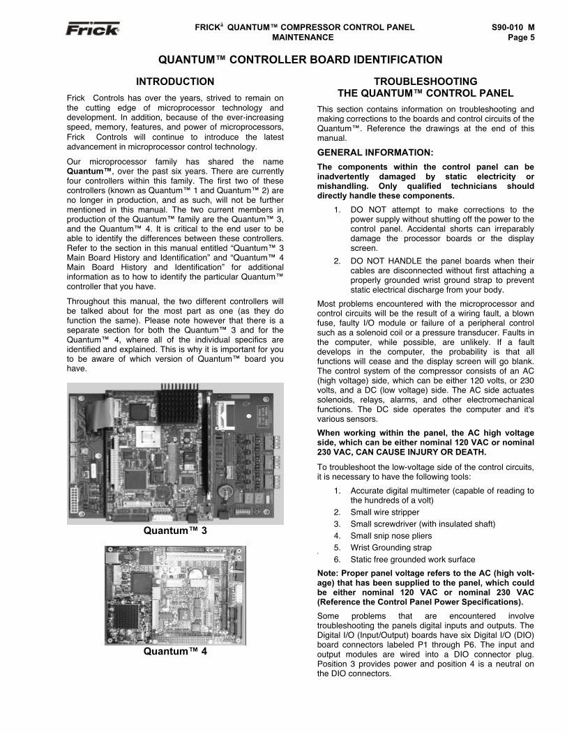
Our microprocessor family has shared the nameQuantum™, over the past six years. There are currentlyfour controllers within this family. The first two of thesecontrollers (known as Quantum™ 1 and Quantum™ 2) areno longer in production, and as such, will not be furthermentioned in this manual. The two current members inproduction of the Quantum™ family are the Quantum™ 3,and the Quantum™ 4. It is critical to the end user to beable to identify the differences between these controllers.Refer to the section in this manual entitled “Quantum™ 3Main Board History and Identification” and “Quantum™ 4Main Board History and Identification” for additionalinformation as to how to identify the particular Quantum™controller that you have.
Throughout this manual, the two different controllers willbe talked about for the most part as one (as they dofunction the same). Please note however that there is aseparate section for both the Quantum™ 3 and for theQuantum™ 4, where all of the individual specifics areidentified and explained. This is why it is important for youto be aware of which version of Quantum™ board youhave.
Quantum™ 3
Quantum™ 4
TROUBLESHOOTINGTHE QUANTUM™ CONTROL PANEL
This section contains information on troubleshooting andmaking corrections to the boards and control circuits of theQuantum™. Reference the drawings at the end of thismanual.
GENERAL INFORMATION:
The components within the control panel can beinadvertently damaged by static electricity ormishandling. Only qualified technicians shoulddirectly handle these components.
1. DO NOT attempt to make corrections to thepower supply without shutting off the power to thecontrol panel. Accidental shorts can irreparablydamage the processor boards or the displayscreen.
2. DO NOT HANDLE the panel boards when theircables are disconnected without first attaching aproperly grounded wrist ground strap to preventstatic electrical discharge from your body.
Most problems encountered with the microprocessor andcontrol circuits will be the result of a wiring fault, a blownfuse, faulty I/O module or failure of a peripheral controlsuch as a solenoid coil or a pressure transducer. Faults inthe computer, while possible, are unlikely. If a faultdevelops in the computer, the probability is that allfunctions will cease and the display screen will go blank.The control system of the compressor consists of an AC(high voltage) side, which can be either 120 volts, or 230volts, and a DC (low voltage) side. The AC side actuatessolenoids, relays, alarms, and other electromechanicalfunctions. The DC side operates the computer and it'svarious sensors.
When working within the panel, the AC high voltageside, which can be either nominal 120 VAC or nominal230 VAC, CAN CAUSE INJURY OR DEATH.
To troubleshoot the low-voltage side of the control circuits,it is necessary to have the following tools:
1. Accurate digital multimeter (capable of reading tothe hundreds of a volt)
2. Small wire stripper3. Small screwdriver (with insulated shaft)4. Small snip nose pliers5. Wrist Grounding strap
2
6. Static free grounded work surface
Note: Proper panel voltage refers to the AC (high volt-age) that has been supplied to the panel, which couldbe either nominal 120 VAC or nominal 230 VAC(Reference the Control Panel Power Specifications).
Some problems that are encountered involvetroubleshooting the panels digital inputs and outputs. TheDigital I/O (Input/Output) boards have six Digital I/O (DIO)board connectors labeled P1 through P6. The input andoutput modules are wired into a DIO connector plug.Position 3 provides power and position 4 is a neutral onthe DIO connectors.
S90-010 M FRICK QUANTUM™ COMPRESSOR CONTROL PANELPage 6 MAINTENANCE
WHAT TO DO BEFORE CALLING THE FACTORY
When someone calls in to the factory with a suspectedQuantum™ problem, sometimes the person calling doesn'tprovide enough information. This is because they mostlikely are not aware of the type of information that wouldbe useful to factory personnel in helping to identify andcorrect the problem. An example of this is the statementthat the Quantum™ is not “booting” (the main processorboard is not starting). Unfortunately, this description isusually vague and only means that there is nothing on thedisplay. A blank screen could be the result of manydifferent problems. Following is a list of possible reasonsfor no display:
• No power
• Loose or Faulty Display Cable or Inverter Cable
• Bad Display
• Bad Backlight Inverter
• Bad Backlight Fluorescent Tube
• Wrong Combination of Display, Cable, Inverter,or Software
• Faulty CPU Board
Before calling the factory for assistance, review theinformation on the following pages and try to discover andresolve your Quantum™ problem. The actual cause ofmost problems is usually not with the Quantum™ itself,but with something external to the Quantum™. However,on the rare occasion that the problem has been identifiedas being the Quantum™ controller, use the followingsection as a guideline for replacing it.
REPLACING THE QUANTUM™ BOARD
The Flash Card memory load is done prior to the board tothe board shipping. The customer will still need to eitherhave their settings manually recorded, or saved to a FlashCrad, so that the new board can be setup the same as theold one. It is suggested that the operator first record allcontrol setpoints prior to board replacement. FactorySetup settings will also be lost. The setpoint datasheets are useful for recording this information. AMaintenance Flashcard may also be purchased that willallow these setpoints to be saved electronically, and maybe downloaded at a later time. Make sure that the operatorcan access Factory Setup to restore all compressorspecific settings.
The procedure to replace the main board is outlinedbelow:
1. Shut off control power.
2. Remove the old board from the machine and thenew board from its packing and place both on ananti-static surface.
3. Ensure that the jumpers on the new board are setthe same as those on the old board.
4. Install the modified replacement board into thepanel.
5. If program changes are necessary through aFlash Card download, then follow the directionsin the Factory Setup manual (S90-010 FSI) forthe procedure to reload a program Flash Card.
FRICK QUANTUM™ COMPRESSOR CONTROL PANEL S90-010 M MAINTENANCE Page 7
QUANTUM™ 3 CONTROLLER
WHAT SHOULD OCCUR WHEN POWERING UPTHE PANEL
The first thing that should be checked whentroubleshooting the Quantum™ is it’s powering upsequence.
When powering up the Quantum™, the followingsequence of events are indicative of a properly workingmain processor board:
• The LED’s for +5V, +12V, and –12V will turn onsolid. (Lower left corner of Main PCB)
• LED KB will begin to blink. (Left side of MainPCB)
• Several initialization screens will appear (thesewill look very similar to the way the screen of adesktop computer appears when it is booting.
• The last of the initialization screens is the“System Configuration” screen.
• Various POST codes will appear.
• The screen will go then show Loading…
• The “Operating Status” screen is shown.
After the Quantum™ has properly powered up, thefollowing sequence of events is indicative of propercommunication to the analog and digital boards:
• The TX/RX LED’s near the white connector willbegin to blink.
• The Analog and Digital I/O boards TX/RX lightsshould be blinking.
• Each I/O board should have the power LED (nextto the white connector) lighted and the “Active”LED (next to the blue Dipswitch) should beblinking.
WHAT IF THE “OPERATING STATUS” SCREENIS NOT SHOWN
If the “Operating Status” screen is not shown, check thefollowing items:
1. If no LED’s are lighted, then check AC and DCpower.
2. Check if the lighting of the LED’s is occurring asdescribed in the “What Should Occur WhenPowering Up The Panel” section.
• If the powering up sequence continues torepeat without displaying the “OperatingStatus” screen, then there is a bootingproblem.
3. Check if an error message is displayed whenbooting.
• Be sure to write down any error messagesexactly as they appear.
4. Check that the software is OK:
• Is the correct software installed?
• Did you just install new software?
• If you need to clear the numerical setpointand calibration areas of memory for anyreason, clear the memory as described inthe S90-010 FSI publication. NOTE: Thisinformation will be replaced by factorydefault values, so any setpoint andcalibration data values that need to becustomized must be reentered.
5. Check for bad or loose connections.
6. Check the display. If the CPU board is bootingbut you have no display, check the following:
• Check the LCD backlight tube. Look veryclosely at the display to see if anything isvisible in the dark screen. Using a beam typesource of good lighting, such as a flashlight,look for any “ghost” type image. If it appearsthat there is something on the screen butvery dark, the problem maybe the LCDbacklight tube. On the LG Philips, NEC andSharp displays this tube is field replaceable.On the Samsung LCD display, it is notavailable and the display will have to bereplaced. There may be a sticker on thedisplay mounting plate. If there is, it will havea part number that describes the type ofdisplay. If there is no sticker, you must takethe display apart to identify the displaymanufacturer.
• Verify that both the display cable and theinverter cable are firmly seated. It may benecessary to remove the video cable fromthe back of the LCD display and reseat it tobe sure it is connected properly. Note: Thisis a small connector and caution shouldbe observed so that it is not damageddue to excessive force.
• Check the backlight inverter connector (P4).When the Quantum™ board is mounted inthe panel, this connector is located at themiddle left of the board. The pins on the rightside are odd numbered, with pin P(1) at thebottom -pin P(9) at the top. The pins on theleft side are even numbered, with pin P(2) atthe bottom - pin P(10) at the top. After theQuantum™ has booted, pin P(3) shouldmeasure +2.4 Vdc, pins P(4) and P(5) areDC grounds, and pins P(6) and P(7) shouldmeasure +12 Vdc. A bad inverter will alsocause a dark display.
• Reference the “Display AssemblyComponent Replacement Guide” in the“Identifying the Type of Display” section thatappears later in this manual, and check thatthe LCD, LCD cable, and software versionsare matched correctly.
S90-010 M FRICK QUANTUM™ COMPRESSOR CONTROL PANELPage 8 MAINTENANCE
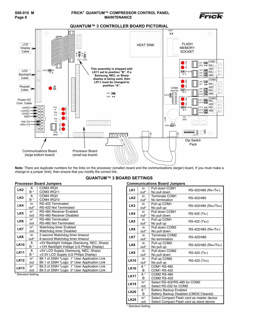
QUANTUM™ 3 CONTROLLER BOARD PICTORIAL
Note: There are duplicate numbers for the links on the processor (smaller) board and the communications (larger) board. If you must make achange to a jumper (link), then ensure that you modify the correct link.
QUANTUM™ 3 BOARD SETTINGSProcessor Board Jumpers
LK2 AB *
COM3 IRQ4COM3 IRQ11
LK3 AB *
COM4 IRQ3COM4 IRQ10
LK4 inout*
RS-422 TerminatedRS-422 Not Terminated
LK5 in*out
RS-485 Receiver EnabledRS-485 Receiver Disabled
LK6 in*out
RS-485 TerminatedRS-485 Not Terminated
LK7 in*out
Watchdog timer EnabledWatchdog timer Disabled
LK8 inout*
2 second Watchdog timer timeout8 second Watchdog timer timeout
LK10 AB *
+5V Backlight Voltage (Samsung, NEC, Sharp)+12V Backlight Voltage (LG Philips Display)
LK11 AB *
+5V LCD Supply (Samsung, NEC, Sharp)+3.3V LCD Supply (LG Philips Display)
LK12 in*out
Bit 1 of 259H “Logic 1” User Application LinkBit 1 of 259H “Logic 0” User Application Link
LK13 in*out
Bit 2 of 259H “Logic 1” User Application LinkBit 2 of 259H “Logic 0” User Application Link
* Standard Setting
Communications Board Jumpers
LK1 inout*
Pull down COM1No pull down RS-422/485 (Rx-/Tx-)
LK2 inout*
Terminate COM1No termination RS-422/485
LK3 inout*
Pull up COM1No pull up RS-422/485 (Rx+/Tx+)
LK4 inout*
Pull down COM1No pull down RS-422 (Tx-)
LK5 inout*
Pull up COM1No pull up RS-422 (Tx+)
LK6 inout*
Pull down COM2No pull down RS-422/485 (Rx-/Tx-)
LK7 inout*
Terminate COM2No termination RS-422/485
LK8 inout*
Pull up COM2No pull up RS-422/485 (Rx+/Tx+)
LK9 inout*
Pull down COM2No pull down RS-422 (Tx-)
LK10 inout*
Pull up COM2No pull up RS-422 (Tx+)
LK16 A *B
COM1 RS-485COM1 RS-422
LK17 A *B
COM2 RS-485COM2 RS-422
LK19 in*out
Select RS-422/RS-485 for COM2Select RS-232 for COM2
LK20 A *B
Battery Backup EnabledBattery Backup Disabled (CMOS Cleared)
LK25 in*out
Select Compact Flash card as master deviceSelect Compact Flash card as slave device
* Standard Setting
COM2
-12V+5VTP3
+5
TP4+12
TP5-12
RX
4TX
4
TP6GND
+12
Power-I/OCom. Cable
+12VDC-12VDC
GND
-RX/-TX+RX/+TX
LK11
BA
LK10
BA
KB
This assembly is shipped withLK11 set to position “B”. If a
Samsung, NEC, or Sharpdisplay is being used, thenLK11 must be changed to
position “A”.KeypadCable
LK7
LK8
LCDDisplayCable
LCDBacklight
Cable
LK24B A
HEAT SINK
COM2RS232
LK19
FLASHMEMORYSOCKET
SW
Dip SwitchPack
BA
T1
SW
2
ON
1 2 3 4 5 6 7 8
LK20B A
P7
P7
TP1GND
COM31
2
3
4
RS-422RS-485
LK12LK11
LK13LK14LK15
TX3
RX
3
LK18B A
B A
1
2
3
4
RS-422RS-485
LK6
LK8LK9
LK10
LK7TX2
RX
2
LK17
COM1LK1LK2
LK3LK4LK5
1
2
3
4
RS-422RS-485
LK16B A
TX1
RX
1
LK25
+5VDC
Communications Board(large bottom board)
Processor Board(small top board)
FRICK QUANTUM™ COMPRESSOR CONTROL PANEL S90-010 M MAINTENANCE Page 9
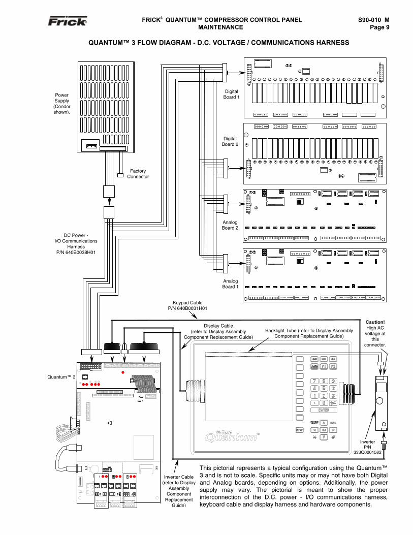
QUANTUM™ 3 FLOW DIAGRAM - D.C. VOLTAGE / COMMUNICATIONS HARNESS
Display (refer tothe chart onpage 34 to
identify type ofdisplay).
Backlight Tube (refer to Display AssemblyComponent Replacement Guide)
Caution!High AC
voltage atthis
connector.
PowerSupply(Condorshown).
DC Power -I/O Communications
HarnessP/N 640B0038H01
InverterP/N
333Q0001582
Keypad CableP/N 640B0031H01
Display Cable(refer to Display Assembly
Component Replacement Guide)
This pictorial represents a typical configuration using the Quantum™3 and is not to scale. Specific units may or may not have both Digitaland Analog boards, depending on options. Additionally, the powersupply may vary. The pictorial is meant to show the properinterconnection of the D.C. power - I/O communications harness,keyboard cable and display harness and hardware components.
Inverter Cable(refer to Display
AssemblyComponent
ReplacementGuide)
Quantum™ 3
DigitalBoard 1
DigitalBoard 2
AnalogBoard 2
AnalogBoard 1
FactoryConnector
S90-010 M FRICK QUANTUM™ COMPRESSOR CONTROL PANELPage 10 MAINTENANCE
QUANTUM™ 4 CONTROLLER
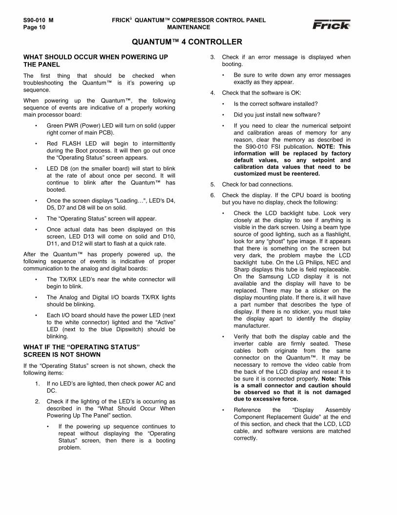
WHAT SHOULD OCCUR WHEN POWERING UPTHE PANEL
The first thing that should be checked whentroubleshooting the Quantum™ is it’s powering upsequence.
When powering up the Quantum™, the followingsequence of events are indicative of a properly workingmain processor board:
• Green PWR (Power) LED will turn on solid (upperright corner of main PCB).
• Red FLASH LED will begin to intermittentlyduring the Boot process. It will then go out oncethe “Operating Status” screen appears.
• LED D8 (on the smaller board) will start to blinkat the rate of about once per second. It willcontinue to blink after the Quantum™ hasbooted.
• Once the screen displays "Loading…", LED's D4,D5, D7 and D8 will be on solid.
• The “Operating Status” screen will appear.
• Once actual data has been displayed on thisscreen, LED D13 will come on solid and D10,D11, and D12 will start to flash at a quick rate.
After the Quantum™ has properly powered up, thefollowing sequence of events is indicative of propercommunication to the analog and digital boards:
• The TX/RX LED’s near the white connector willbegin to blink.
• The Analog and Digital I/O boards TX/RX lightsshould be blinking.
• Each I/O board should have the power LED (nextto the white connector) lighted and the “Active”LED (next to the blue Dipswitch) should beblinking.
WHAT IF THE “OPERATING STATUS”SCREEN IS NOT SHOWN
If the “Operating Status” screen is not shown, check thefollowing items:
1. If no LED’s are lighted, then check power AC andDC.
2. Check if the lighting of the LED’s is occurring asdescribed in the “What Should Occur WhenPowering Up The Panel” section.
• If the powering up sequence continues torepeat without displaying the “OperatingStatus” screen, then there is a bootingproblem.
3. Check if an error message is displayed whenbooting.
• Be sure to write down any error messagesexactly as they appear.
4. Check that the software is OK:
• Is the correct software installed?
• Did you just install new software?
• If you need to clear the numerical setpointand calibration areas of memory for anyreason, clear the memory as described inthe S90-010 FSI publication. NOTE: Thisinformation will be replaced by factorydefault values, so any setpoint andcalibration data values that need to becustomized must be reentered.
5. Check for bad connections.
6. Check the display. If the CPU board is bootingbut you have no display, check the following:
• Check the LCD backlight tube. Look veryclosely at the display to see if anything isvisible in the dark screen. Using a beam typesource of good lighting, such as a flashlight,look for any “ghost” type image. If it appearsthat there is something on the screen butvery dark, the problem maybe the LCDbacklight tube. On the LG Philips, NEC andSharp displays this tube is field replaceable.On the Samsung LCD display it is notavailable and the display will have to bereplaced. There may be a sticker on thedisplay mounting plate. If there is, it will havea part number that describes the type ofdisplay. If there is no sticker, you must takethe display apart to identify the displaymanufacturer.
• Verify that both the display cable and theinverter cable are firmly seated. Thesecables both originate from the sameconnector on the Quantum™. It may benecessary to remove the video cable fromthe back of the LCD display and reseat it tobe sure it is connected properly. Note: Thisis a small connector and caution shouldbe observed so that it is not damageddue to excessive force.
• Reference the “Display AssemblyComponent Replacement Guide” at the endof this section, and check that the LCD, LCDcable, and software versions are matchedcorrectly.
FRICK QUANTUM™ COMPRESSOR CONTROL PANEL S90-010 M MAINTENANCE Page 11
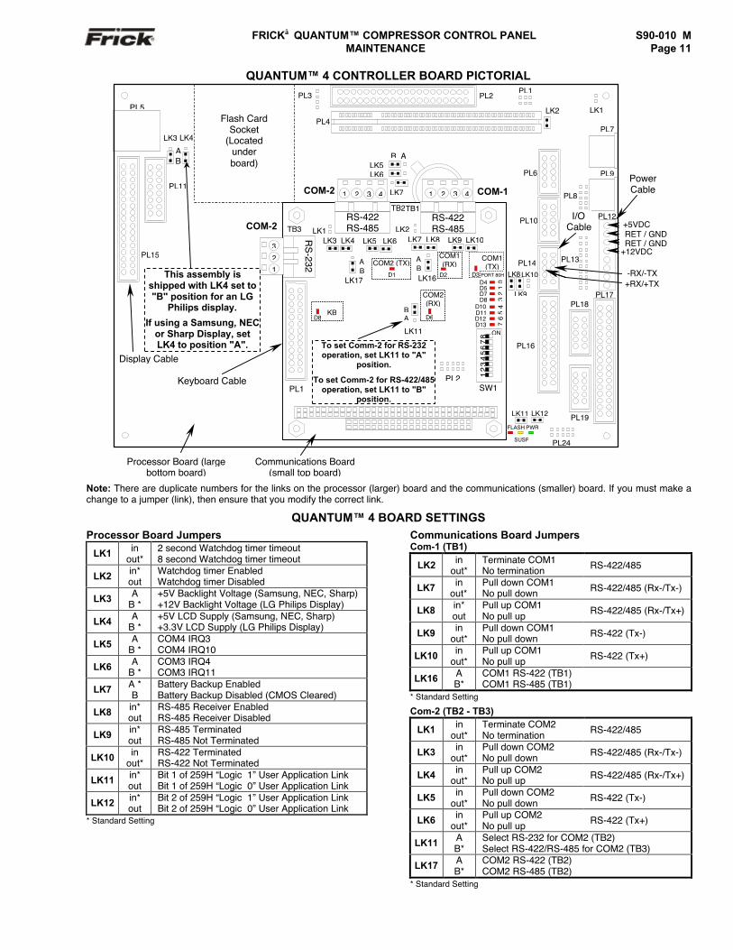
QUANTUM™ 4 CONTROLLER BOARD PICTORIAL
Note: There are duplicate numbers for the links on the processor (larger) board and the communications (smaller) board. If you must make achange to a jumper (link), then ensure that you modify the correct link.
QUANTUM™ 4 BOARD SETTINGSProcessor Board Jumpers
LK1 inout*
2 second Watchdog timer timeout8 second Watchdog timer timeout
LK2 in*out
Watchdog timer EnabledWatchdog timer Disabled
LK3 AB *
+5V Backlight Voltage (Samsung, NEC, Sharp)+12V Backlight Voltage (LG Philips Display)
LK4 AB *
+5V LCD Supply (Samsung, NEC, Sharp)+3.3V LCD Supply (LG Philips Display)
LK5 AB *
COM4 IRQ3COM4 IRQ10
LK6 AB *
COM3 IRQ4COM3 IRQ11
LK7 A *B
Battery Backup EnabledBattery Backup Disabled (CMOS Cleared)
LK8 in*out
RS-485 Receiver EnabledRS-485 Receiver Disabled
LK9 in*out
RS-485 TerminatedRS-485 Not Terminated
LK10 inout*
RS-422 TerminatedRS-422 Not Terminated
LK11 in*out
Bit 1 of 259H “Logic 1” User Application LinkBit 1 of 259H “Logic 0” User Application Link
LK12 in*out
Bit 2 of 259H “Logic 1” User Application LinkBit 2 of 259H “Logic 0” User Application Link
* Standard Setting
Communications Board JumpersCom-1 (TB1)
LK2 inout*
Terminate COM1No termination RS-422/485
LK7 inout*
Pull down COM1No pull down RS-422/485 (Rx-/Tx-)
LK8 in*out
Pull up COM1No pull up RS-422/485 (Rx-/Tx+)
LK9 inout*
Pull down COM1No pull down RS-422 (Tx-)
LK10 inout*
Pull up COM1No pull up RS-422 (Tx+)
LK16 AB*
COM1 RS-422 (TB1)COM1 RS-485 (TB1)
* Standard Setting
Com-2 (TB2 - TB3)
LK1 inout*
Terminate COM2No termination RS-422/485
LK3 inout*
Pull down COM2No pull down RS-422/485 (Rx-/Tx-)
LK4 inout*
Pull up COM2No pull up RS-422/485 (Rx-/Tx+)
LK5 inout*
Pull down COM2No pull down RS-422 (Tx-)
LK6 inout*
Pull up COM2No pull up RS-422 (Tx+)
LK11 AB*
Select RS-232 for COM2 (TB2)Select RS-422/RS-485 for COM2 (TB3)
LK17 AB*
COM2 RS-422 (TB2)COM2 RS-485 (TB2)
* Standard Setting
PWR
SUSP
FLASH
LK11 LK12
PL24
PL3
PL
LK9
LK8LK10
PL16
LK1
PL7
PL9
LK2
PL17
PL12
PL19
PL18
PL14
PL10
PL6
PL2
PL4
PL1
Flash CardSocket
(Locatedunderboard)
PL3
PL5
PL11
LK3
AB
LK4
PL15
+5VDC
+12VDC
RET / GNDRET / GND
+RX/+TX-RX/-TX
PowerCable
PL8
I/O Cable
TB1TB2
LK2COM-2 TB3
RS
-232
321
PL13
This assembly isshipped with LK4 set to"B" position for an LG
Philips display.
If using a Samsung, NECor Sharp Display, setLK4 to position "A".
Keyboard Cable
Display Cable
LK6
B ALK5
LK7COM-2 COM-11 2 3 4 1 2 3 4
LK8LK7 LK10LK9
D3LK16
AB
AB
PL2
34
56
70
12
D8D10D11D12
PORT 80H
D4D5D7
D13
SW1
ON
1 2
3 4
5 6
7 8
D6
D2
LK11
BA
LK1LK4LK3 LK6LK5
D1
D8
LK17
To set Comm-2 for RS-232operation, set LK11 to "A"
position.
To set Comm-2 for RS-422/485operation, set LK11 to "B"
position.
RS-422RS-485
RS-422RS-485
PL1
Processor Board (largebottom board)
Communications Board(small top board)
COM2 (TX)COM1(RX)
COM1(TX)
KB
COM2(RX)
S90-010 M FRICK QUANTUM™ COMPRESSOR CONTROL PANELPage 12 MAINTENANCE
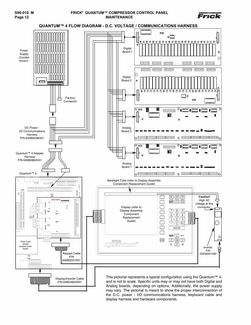
QUANTUM™ 4 FLOW DIAGRAM - D.C. VOLTAGE / COMMUNICATIONS HARNESS
Keypad CableP/N
640B0031H01
Quantum™ 4
Quantum™ 4 AdapterHarness
P/N 649B0862H01
DigitalBoard 1
DigitalBoard 2
AnalogBoard 2
AnalogBoard 1
PowerSupply(Condorshown).
FactoryConnector
DC Power -I/O Communications
HarnessP/N 640B0038H01
InverterP/N
333Q0001582
This pictorial represents a typical configuration using the Quantum™ 4,and is not to scale. Specific units may or may not have both Digital andAnalog boards, depending on options. Additionally, the power supplymay vary. The pictorial is meant to show the proper interconnection ofthe D.C. power - I/O communications harness, keyboard cable anddisplay harness and hardware components.
Display/Inverter CableP/N 649D4824H01
P
P
Flash Cardsocket
located underboard
1
2
3
4
3 2 1
3
1
2
4
Backlight Tube (refer to Display AssemblyComponent Replacement Guide)
Display (refer toDisplay Assembly
ComponentReplacement
Guide)
Caution!High AC
voltage at thisconnector.
FRICK QUANTUM™ COMPRESSOR CONTROL PANEL S90-010 M MAINTENANCE Page 13
DIGITAL BOARDS
The information that follows in this section can help locateproblems that can occur with Digital Input and Outputcircuit boards, and their interaction with the Quantum™controller.
Digital Board Description
The Digital Board is actually a small microprocessor boardand programmed to control discrete outputs, or acceptingdiscrete inputs, from external electrical devices. EachDigital Board has the capability of 24 independentchannels or I/O (Input/Output). With the Quantum™Compressor Control, these I/O channels are dedicated asto their function, through the operating system (software),enabled options and external wiring. Each channel that isused by the software will have a module plugged into it. Ayellow module indicates that it is used for Inputs. A blackmodule is used for Outputs. The standard Quantum™compressor control can have up to two Digital Boards(depending on options).
Communications LED's
The Quantum™ controller is in constant communicationwith all Digital (and Analog) Boards. You will notice oneach Digital and Analog board, that there are a pair ofLED's that are labeled as RX and TX. These lettersrepresent Receive (RX) and Transmit (TX). These LED'sshould be flashing at a fairly high rate during normaloperation. This indicates that the Quantum™, and theDigital Board that you are looking at, are properlycommunicating with each other.
• Reference the “JUMPER AND DIPSWITCHSETTINGS" section later in this manual. Thissection contains the dipswitch settings foraddressing the Digital I/O Boards numbers (1)through (6), although only the first two boardscan be addressed. When these switches areproperly set, the Quantum™ is able to seriallycommunicate with each I/O board and providecontrol signals and data exchange. If theseswitches are not properly set, the result will belost or failed communications (displayed in the“Communications Status” box on the Homescreen), or the wrong outputs being energized, orthe wrong inputs being received.
Connections to the Quantum™
As stated earlier, the Quantum™ standard compressorcontrol system utilizes up to two Digital, and two AnalogBoards. To connect all of these boards together so thatthe Quantum™ can control them, they must beinterconnected with a wiring harness that provides all ofthe necessary D.C. voltage requirements, as well as thecommunications capabilities. A diagram of this wiringharness can be found later in this manual (see the PowerI/O Wiring Harness drawing). This harness has an 18 pinconnector at one end that plugs into the Quantum™.Another connector plugs into the power supply. Theremaining four connectors (16 pin) will plug into each ofthe Digital and Analog Boards in the system (up to fourtotal).
Upon close examination of this harness, you will noticethat each of the connectors for both the Quantum™ andthe four I/O boards, have two rows of connections. Thewires that are inserted into the positions of one row, areinternally daisychained on each I/O board, to continue thevoltages and signals to the adjacent row. Therefore, anytime that a connector is unplugged from the daisychain,these voltages and signals cannot continue through thedaisychain to the next board. Whenever a plug is not to beinserted into a board, either for service or if not all boardsare present because of the options that are not beingused, then a shunting plug (refer to Recommended SpareParts list) must be installed onto the open connector.
The four wires that feed from the power supply to theQuantum™ provide all of the necessary D.C. voltage thatis required (+5 Vdc, -12 Vdc, +12 Vdc, and Return orCommon). The voltages are passed through the connectoron the Quantum™, and two new signals are generated bythe Quantum™ to be passed on through the daisychain tothe I/O boards. These two signals are the RX (receive)and TX (transmit). These signals are the means by whichthe Quantum™ communicates to the I/O.
The Digital Boards only require the +5 Vdc voltage and theReturn (or common) for logic power. The communicationssignals (RX & TX) are required by all boards.
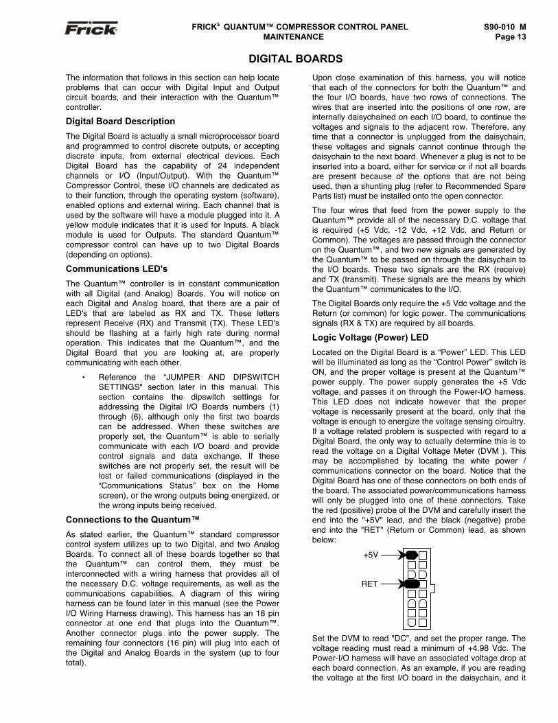
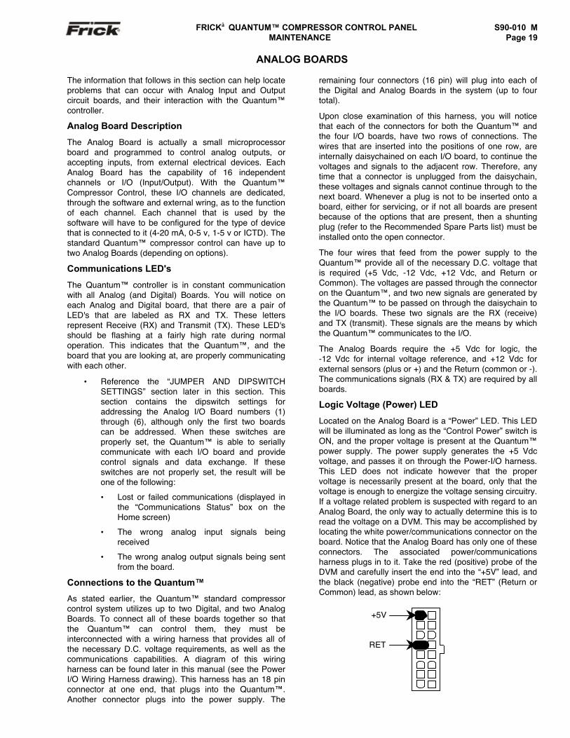
Logic Voltage (Power) LED
Located on the Digital Board is a “Power” LED. This LEDwill be illuminated as long as the “Control Power” switch isON, and the proper voltage is present at the Quantum™power supply. The power supply generates the +5 Vdcvoltage, and passes it on through the Power-I/O harness.This LED does not indicate however that the propervoltage is necessarily present at the board, only that thevoltage is enough to energize the voltage sensing circuitry.If a voltage related problem is suspected with regard to aDigital Board, the only way to actually determine this is toread the voltage on a Digital Voltage Meter (DVM ). Thismay be accomplished by locating the white power /communications connector on the board. Notice that theDigital Board has one of these connectors on both ends ofthe board. The associated power/communications harnesswill only be plugged into one of these connectors. Takethe red (positive) probe of the DVM and carefully insert theend into the "+5V" lead, and the black (negative) probeend into the "RET" (Return or Common) lead, as shownbelow:
Set the DVM to read "DC", and set the proper range. Thevoltage reading must read a minimum of +4.98 Vdc. ThePower-I/O harness will have an associated voltage drop ateach board connection. As an example, if you are readingthe voltage at the first I/O board in the daisychain, and it
+5V
RET
S90-010 M FRICK QUANTUM™ COMPRESSOR CONTROL PANELPage 14 MAINTENANCE
reads 4.98 Vdc, you can be assured that the voltage at thesubsequent connections for the remaining boards will belower yet. The voltage will need to be corrected for properoperation of the system. The cause for a low voltagereading could be:
• The Quantum™ power supply may needadjustment (see the section on power supplies).
• The Power-I/O communications harness has aproblem (a new harness may be needed).
• A problem may exist with one of the I/O boards(Digital or Analog).
• If the power LED is not lighted, check the cablefor proper connectivity. Note: Each boardprovides the necessary connections to feedall signals to the following connectors. If theauxiliary Analog or Digital Board is notpresent then a jumper plug (seeRecommended Spare Parts List) must beinstalled to daisychain the signals.
The most common symptom that is be exhibited by a low+5 Vdc voltage to the Digital Boards is an alarm messagethat reads "Digital Board Reset Shutdown".
Active LED
The Digital Boards have an “Active” LED indicator on theboard that blinks when the board’s software is running.
If the “Active” LED is not blinking, check to ensure that theEPROM is installed properly. The EPROM is located inchip slot U8, next to the power connector.
Digital Inputs
A Digital Input is the portion of the hardware that allowsdevices such as limit switches, relay contacts, and levelswitches, to interface with the Quantum™. The softwareprogram within the Quantum™ is constantly “looking” atthese Input channels, via communications, and basedupon whether a control voltage is present or not, willprovide the necessary control for an associated Outputchannel. For instance, if a control voltage is present on theOil Level Sensor input, the software will determine that theSeparator has sufficient oil level for the oil heaters to beenergized (if the temperature of the oil is also sensed tobe low. Temperature sensing will be discussed in theAnalog Input section).
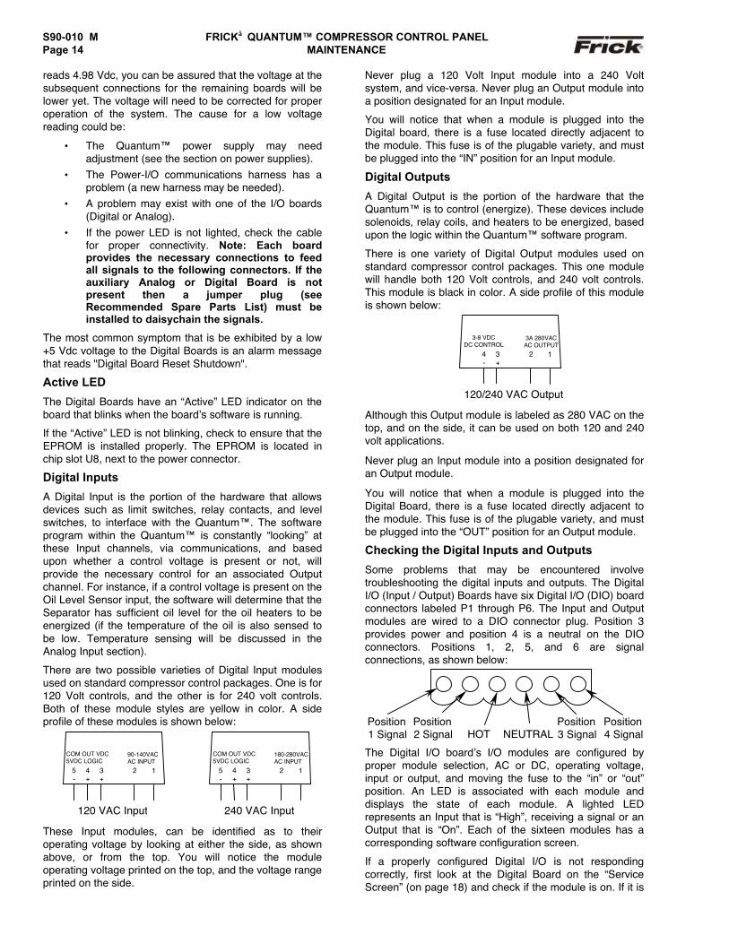
There are two possible varieties of Digital Input modulesused on standard compressor control packages. One is for120 Volt controls, and the other is for 240 volt controls.Both of these module styles are yellow in color. A sideprofile of these modules is shown below:
These Input modules, can be identified as to theiroperating voltage by looking at either the side, as shownabove, or from the top. You will notice the moduleoperating voltage printed on the top, and the voltage rangeprinted on the side.
Never plug a 120 Volt Input module into a 240 Voltsystem, and vice-versa. Never plug an Output module intoa position designated for an Input module.
You will notice that when a module is plugged into theDigital board, there is a fuse located directly adjacent tothe module. This fuse is of the plugable variety, and mustbe plugged into the “IN” position for an Input module.
Digital Outputs
A Digital Output is the portion of the hardware that theQuantum™ is to control (energize). These devices includesolenoids, relay coils, and heaters to be energized, basedupon the logic within the Quantum™ software program.
There is one variety of Digital Output modules used onstandard compressor control packages. This one modulewill handle both 120 Volt controls, and 240 volt controls.This module is black in color. A side profile of this moduleis shown below:
Although this Output module is labeled as 280 VAC on thetop, and on the side, it can be used on both 120 and 240volt applications.
Never plug an Input module into a position designated foran Output module.
You will notice that when a module is plugged into theDigital Board, there is a fuse located directly adjacent tothe module. This fuse is of the plugable variety, and mustbe plugged into the “OUT” position for an Output module.
Checking the Digital Inputs and Outputs
Some problems that may be encountered involvetroubleshooting the digital inputs and outputs. The DigitalI/O (Input / Output) Boards have six Digital I/O (DIO) boardconnectors labeled P1 through P6. The Input and Outputmodules are wired to a DIO connector plug. Position 3provides power and position 4 is a neutral on the DIOconnectors. Positions 1, 2, 5, and 6 are signalconnections, as shown below:
The Digital I/O board’s I/O modules are configured byproper module selection, AC or DC, operating voltage,input or output, and moving the fuse to the “in” or “out”position. An LED is associated with each module anddisplays the state of each module. A lighted LEDrepresents an Input that is “High”, receiving a signal or anOutput that is “On”. Each of the sixteen modules has acorresponding software configuration screen.
If a properly configured Digital I/O is not respondingcorrectly, first look at the Digital Board on the “ServiceScreen” (on page 18) and check if the module is on. If it is
5-
4+
3+
COM OUT VDC5VDC LOGIC
2∼
1
90-140VACAC INPUT
120 VAC Input
5-
4+
3+
COM OUT VDC5VDC LOGIC
2∼
1
180-280VACAC INPUT
240 VAC Input
4-
3+
3-8 VDCDC CONTROL
2∼
1
3A 280VACAC OUTPUT
120/240 VAC Output
HOT NEUTRALPosition1 Signal
Position2 Signal
Position3 Signal
Position4 Signal
FRICK QUANTUM™ COMPRESSOR CONTROL PANEL S90-010 M MAINTENANCE Page 15
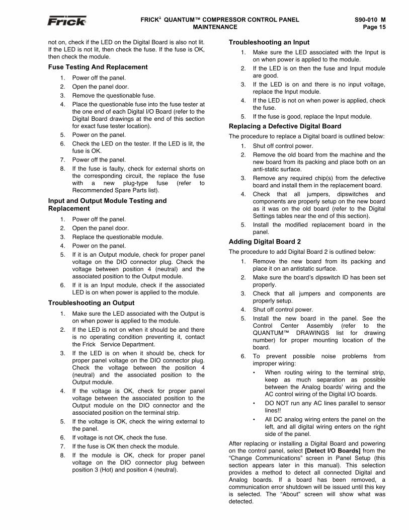
not on, check if the LED on the Digital Board is also not lit.If the LED is not lit, then check the fuse. If the fuse is OK,then check the module.
Fuse Testing And Replacement
1. Power off the panel.2. Open the panel door.3. Remove the questionable fuse.4. Place the questionable fuse into the fuse tester at
the one end of each Digital I/O Board (refer to theDigital Board drawings at the end of this sectionfor exact fuse tester location).
5. Power on the panel.6. Check the LED on the tester. If the LED is lit, the
fuse is OK.7. Power off the panel.8. If the fuse is faulty, check for external shorts on
the corresponding circuit, the replace the fusewith a new plug-type fuse (refer toRecommended Spare Parts list).
Input and Output Module Testing andReplacement
1. Power off the panel.2. Open the panel door.3. Replace the questionable module.4. Power on the panel.5. If it is an Output module, check for proper panel
voltage on the DIO connector plug. Check thevoltage between position 4 (neutral) and theassociated position to the Output module.
6. If it is an Input module, check if the associatedLED is on when power is applied to the module.
Troubleshooting an Output
1. Make sure the LED associated with the Output ison when power is applied to the module.
2. If the LED is not on when it should be and thereis no operating condition preventing it, contactthe Frick Service Department.
3. If the LED is on when it should be, check forproper panel voltage on the DIO connector plug.Check the voltage between the position 4(neutral) and the associated position to theOutput module.
4. If the voltage is OK, check for proper panelvoltage between the associated position to theOutput module on the DIO connector and theassociated position on the terminal strip.
5. If the voltage is OK, check the wiring external tothe panel.
6. If voltage is not OK, check the fuse.7. If the fuse is OK then check the module.8. If the module is OK, check for proper panel
voltage on the DIO connector plug betweenposition 3 (Hot) and position 4 (neutral).
Troubleshooting an Input1. Make sure the LED associated with the Input is
on when power is applied to the module.2. If the LED is on then the fuse and Input module
are good.3. If the LED is on and there is no input voltage,
replace the Input module.4. If the LED is not on when power is applied, check
the fuse.5. If the fuse is good, replace the Input module.
Replacing a Defective Digital BoardThe procedure to replace a Digital board is outlined below:
1. Shut off control power.2. Remove the old board from the machine and the
new board from its packing and place both on ananti-static surface.
3. Remove any required chip(s) from the defectiveboard and install them in the replacement board.
4. Check that all jumpers, dipswitches andcomponents are properly setup on the new boardas it was on the old board (refer to the DigitalSettings tables near the end of this section).
5. Install the modified replacement board in thepanel.
Adding Digital Board 2The procedure to add Digital Board 2 is outlined below:
1. Remove the new board from its packing andplace it on an antistatic surface.
2. Make sure the board’s dipswitch ID has been setproperly.
3. Check that all jumpers and components areproperly setup.
4. Shut off control power.5. Install the new board in the panel. See the
Control Center Assembly (refer to theQUANTUM™ DRAWINGS list for drawingnumber) for proper mounting location of theboard.
6. To prevent possible noise problems fromimproper wiring:• When routing wiring to the terminal strip,
keep as much separation as possiblebetween the Analog boards' wiring and theAC control wiring of the Digital I/O boards.
• DO NOT run any AC lines parallel to sensorlines!!
• All DC analog wiring enters the panel on theleft, and all digital wiring enters on the rightside of the panel.
After replacing or installing a Digital Board and poweringon the control panel, select [Detect I/O Boards] from the“Change Communications” screen in Panel Setup (thissection appears later in this manual). This selectionprovides a method to detect all connected Digital andAnalog boards. If a board has been removed, acommunication error shutdown will be issued until this keyis selected. The “About” screen will show what wasdetected.
S90-010 M FRICK QUANTUM™ COMPRESSOR CONTROL PANELPage 16 MAINTENANCE
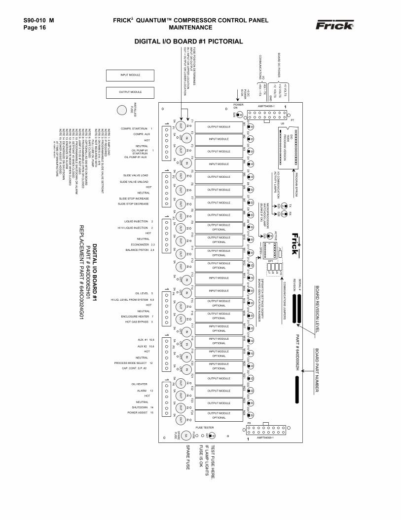
DIGITAL I/O BOARD #1 PICTORIAL
TE
ST
FU
SE
HE
RE
.IF
LAM
P LIG
HT
SF
US
E IS
OK
SP
AR
E F
US
E
5A OU
T
F20
M20INPUT MODULE
OPTIONAL
D20
ININ
1P
55A O
UT
F19
M19INPUT MODULE
OPTIONAL
D19
IN
5A OU
T
F18
M18INPUT MODULE
OPTIONAL
D18
IN
5A OU
T
F17
M17INPUT MODULE
OPTIONAL
D17
IN
1P
45A O
UT
F13
M13
INPUT MODULE
D13
IN
5A
OU
T
IN
F12 M12OUTPUT MODULE
OPTIONAL
D12
5A
OU
T
IN
F11 M11OUTPUT MODULE
OPTIONAL
D11
1P
35A
OU
T
IN
F10 M10OUTPUT MODULE
OPTIONAL
D10
5A
OU
T
IN
F9 M9OUTPUT MODULE
OPTIONAL
D9
5A
OU
T
IN
F8 M8
OUTPUT MODULE
D8
5A
OU
T
IN
F7 M7
OUTPUT MODULE
D7
1P
25A
OU
T
IN
F6 M6
OUTPUT MODULE
D6
5A
OU
T
IN
F5 M5
OUTPUT MODULE
D5
5A OU
T
F4
M4
INPUT MODULE
D4
IN
5A
OU
T
IN
F3 M3
OUTPUT MODULED
3
1P
15A O
UT
F2
M2
INPUT MODULE
D2
IN
INS
TA
LLED
FU
SE
OUTPUT MODULE
POWERON
FU
SE
PO
SIT
ION
DE
TE
RM
INE
SIN
PU
T O
R O
UT
PU
TIN
= INP
UT
OR
UP
PE
R LO
CA
TIO
NO
UT
= OU
TP
UT
OR
LOW
ER
LOC
AT
ION
5A
OU
T
F1 M1
OUTPUT MODULE
D1
D29
1AMP794068-1P
RO
GR
AM
EP
RO
M
DIO
19200P
RO
GR
AM
VE
RS
ION
I/O C
OM
MU
NIC
AT
ION
AC
TIV
ITY
LAM
PS
D25
TX
D26
RX
D28
AC
TIV
E
MIC
RO
PR
OC
ES
SO
RW
AT
CH
DO
G LA
MP
(BLIN
KS
IF O
K)
P8
5A
FU
SE
SP
AR
EF
US
E
D27
FUSE TESTER
1 AMP794068-1
1P
65A
OU
T
IN
F24
M24OUTPUT MODULE
OPTIONAL
D24
1
OP
EN
Frick*
J5
DP1
J7 J8 J9 J10
5A
OU
T
IN
F16
M16OUTPUT MODULE
OPTIONAL
D16
5A
OU
T
IN
F15
M15OUTPUT MODULE
OPTIONAL
D15
5A OU
T
F14
M14
INPUT MODULE
D14
IN
SE
RIA
L #
RE
VIS
ION
DIP
SW
ITC
H S
ET
TIN
GS
SIG
NIF
YB
OA
RD
IDE
NT
IFIC
AT
ION
NU
MB
ER
CO
MM
UN
ICA
TIO
NS
JUM
PE
RS
5A
OU
T
IN
F23
M23
OUTPUT MODULE
D23
5A
OU
T
IN
F22
M22
OUTPUT MODULE
D22
5A
OU
T
IN
F21
M21
OUTPUT MODULE
D21
PA
RT
# 640D0062H
BO
AR
D R
EV
ISIO
N LE
VE
LB
OA
RD
PA
RT
NU
MB
ER
INPUT MODULE
COMPR. START/RUN 1
COMPR. AUX
HOT
NEUTRAL
OIL PUMP #1 1 START/RUN
OIL PUMP #1 AUX
SLIDE VALVE LOAD
SLIDE VALVE UNLOAD
HOT
NEUTRAL
SLIDE STOP INCREASE
SLIDE STOP DECREASE
LIQUID INJECTION 2
HI VI LIQUID INJECTION 2
HOT
NEUTRAL
ECONOMIZER 2,3
BALANCE PISTON 2,4
OIL LEVEL 5
HI LIQ. LEVEL FROM SYSTEM 6,9
HOT
NEUTRAL
ENCLOSURE HEATER 7
HOT GAS BYPASS 3
AUX. #1 10,6
AUX #2 10,6
HOT
NEUTRAL
PROCESS MODE SELECT 12
CAP. CONT. S.P. #2
OIL HEATER
ALARM 13
HOT
NEUTRAL
SHUTDOWN 14
POWER ASSIST 15
DIG
ITA
L I/O
BO
AR
D #1
PA
RT # 640D
0062H01
RE
PLA
CE
ME
NT P
AR
T # 640C0024G
01
NO
TE
1: 2 AM
P LO
AD
NO
TE
2: IF R
EQ
UIR
ED
NO
TE
3: PR
OG
RA
MM
AB
LE S
LIDE
VA
LVE
SE
TP
OIN
TN
OT
E 4: O
N R
WB
’S 316 – 676
NO
TE
5: NO
T R
EQ
UIR
ED
WIT
H F
ULL LU
BE
OIL P
UM
P.
NO
TE
6: SA
FE
CLO
SE
DN
OT
E 7: (O
PT
ION
AL) A
D 590 M
TD
ON
BO
AR
DN
OT
E 8: P
RO
GR
AM
MB
AB
LE O
PE
N O
R C
LOS
ED
NO
TE
9: JUM
P 5 T
O 25 IF
NO
T U
SE
DN
OT
E 10: P
RO
GR
AM
MA
BLE
SH
UT
DO
WN
OR
ALA
RM
NO
TE
11: SE
TP
OIN
T #2 W
HE
N C
LOS
ED
NO
TE
12: ALT
ER
NA
TE
MO
DE
WH
EN
CLO
SE
DN
OTE
13: EN
ER
GIZE
ON
ALA
RM
NO
TE
14: DE
-EN
ER
GIZ
E O
N S
HU
TD
OW
NN
OT
E 15: P
OW
ER
AS
SIS
T IS
AD
DE
D A
T T
IME
OF
MA
NU
FA
CT
UR
E IF
SP
EC
IFIE
D
+5 VO
LTS
+12 VO
LTS
-12 VO
LTSG
ND
-RX
/ -TX
+RX
/ +TX
BO
AR
D D
C P
OW
ERI/O
CO
MM
UN
ICA
TIO
NS
+5 DC
PO
WE
RIS
OK
U8P7
FRICK QUANTUM™ COMPRESSOR CONTROL PANEL S90-010 M MAINTENANCE Page 17
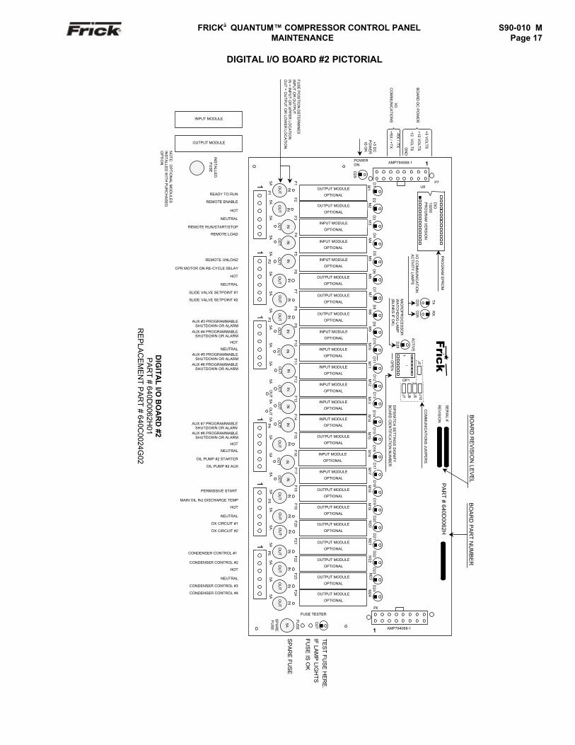
DIGITAL I/O BOARD #2 PICTORIAL
OU
TO
UT
+5 VO
LTS
+12 VO
LTS
-12 VO
LTSGN
D
-RX
/ -TX
+RX
/ +TX
BO
AR
D D
C P
OW
ER
I/OC
OM
MU
NIC
AT
ION
SD
IPS
WIT
CH
SE
TT
ING
S S
IGN
IFY
BO
AR
D ID
EN
TIF
ICA
TIO
N N
UM
BE
R
IN
PA
RT
# 640D0062H
F7
FUSE TESTER
M7
D7
M6
D6
D5
D4
D3
D2
TE
ST
FU
SE
HE
RE
.IF
LAM
P LIG
HT
SF
US
E IS
OK
SP
AR
E F
US
E
M23
D23
M22
D22
M21
D21
BO
AR
D R
EV
ISIO
N LE
VE
LB
OA
RD
PA
RT
NU
MB
ER
5A
OU
T
IN
F24
M24OUTPUT MODULE
OPTIONAL
D24
OUTPUT MODULE
OPTIONAL
OUTPUT MODULE
OPTIONAL
5A
F21 OUTPUT MODULE
OPTIONAL
P8
1 AMP794068-1
M19
D19
M18
D18
M17
D17
M16
D16
M15
D15
M14
D14
DIG
ITA
L I/O
BO
AR
D #2
PA
RT
# 640D0062H
01R
EP
LAC
EM
EN
T P
AR
T # 640C
0024G02
SE
RIA
L #
RE
VIS
ION
CO
MM
UN
ICA
TIO
NS
JUM
PE
RS
Frick*
OUTPUT MODULE
OPTIONAL
OUTPUT MODULE
OPTIONAL
INPUT MODULE
OPTIONAL
OUTPUT MODULE
OPTIONAL
INPUT MODULE
OPTIONAL
INPUT MODULE
OPTIONAL
D28
AC
TIV
E
MIC
RO
PR
OC
ES
SO
RW
AT
CH
DO
G LA
MP
(BLIN
KS
IF O
K)
1
OP
EN
J5
DP1
J7 J8 J9 J10
PR
OG
RA
M E
PR
OM
I/O C
OM
MU
NIC
AT
ION
AC
TIV
ITY
LAM
PS
D25
TX
D26
RX
DIO
19200P
RO
GR
AM
VE
RS
ION
U8
1AMP794068-1
5A
FU
SE
SP
AR
EF
US
E
D27
READY TO RUN
REMOTE ENABLE
HOT
NEUTRAL
REMOTE RUN/START/STOP
REMOTE LOAD
REMOTE UNLOAD
CPR MOTOR ON RE-CYCLE DELAY
HOT
NEUTRAL
SLIDE VALVE SETPOINT #1
SLIDE VALVE SETPOINT #2
AUX #3 PROGRAMMABLESHUTDOWN OR ALARM
AUX #4 PROGRAMMABLESHUTDOWN OR ALARM
HOT
NEUTRALAUX #5 PROGRAMMABLE
SHUTDOWN OR ALARM
AUX #6 PROGRAMMABLESHUTDOWN OR ALARM
AUX #7 PROGRAMMABLESHUTDOWN OR ALARM
AUX #8 PROGRAMMABLE SHUTDOWN OR ALARM
HOT
NEUTRAL
OIL PUMP #2 STARTER
OIL PUMP #2 AUX
PERMISSIVE START
MAIN OIL INJ DISCHARGE TEMP
HOT
NEUTRAL
DX CIRCUIT #1
DX CIRCUIT #2
CONDENSER CONTROL #1
CONDENSER CONTROL #2
HOT
NEUTRAL
CONDENSER CONTROL #3
CONDENSER CONTROL #4
1
INPUT MODULE
OPTIONAL
OUTPUT MODULE
OPTIONAL
1P
45A O
UT
F14
INPUT MODULE
OPTIONAL
INPUT MODULE
OPTIONAL
5A OU
T
F13
M13INPUT MODULE
OPTIONAL
D13
IN
INPUT MODULE
OPTIONAL
IN
OUTPUT MODULE
OPTIONAL
OUTPUT MODULE
OPTIONAL
OUTPUT MODULE
OPTIONAL
F17
5A
F16
5A
F15
OU
T
IN
OU
T
INPUT MODULE
OPTIONALIN
P5
5A
F19
5A
F18
5A OU
T
IN
OU
T
IN
5A
F20
M20
D20
1P
65A
OU
T
IN
F23
5A
OU
T
IN
F22
OU
T
IN
OU
T
IN
OU
T
IN
M5
M4
M3
M2
+5 DC
PO
WE
RIS
OK
P7
IN
OU
T
5A F3
1P
15A
F2
NO
TE
: OP
TIO
NA
L MO
DU
LES
INS
TA
LLED
WIT
H P
UR
CH
AS
ED
OP
TIO
N
INS
TA
LLED
FU
SE
OUTPUT MODULE
POWERON
FU
SE
PO
SIT
ION
DE
TE
RM
INE
SIN
PU
T O
R O
UT
PU
TIN
= INP
UT
OR
UP
PE
R LO
CA
TIO
NO
UT
= OU
TP
UT
OR
LOW
ER
LOC
AT
ION
5A
OU
T
F1 M1OUTPUT MODULE
OPTIONAL
D1
D29
INPUT MODULE
OU
T
IN
OU
T
IN
5A
F12 M12
D12
OU
T
INPUT MODULE
OPTIONAL
OU
T
IN
5A
F11 M11
D11
INPUT MODULE
OPTIONAL
5A
F10 M10
D10
5A
F9 M9
D9
5A
OU
T
IN
F8 M8
OUTPUT MODULE
OPTIONAL
D8
OU
T
IN
5A OU
T
IN
P2
5A
OU
T
IN
F6
5A F5
5A OU
T
F4
IN
1P
3
1
OU
T
ININ
S90-010 M FRICK QUANTUM™ COMPRESSOR CONTROL PANELPage 18 MAINTENANCE
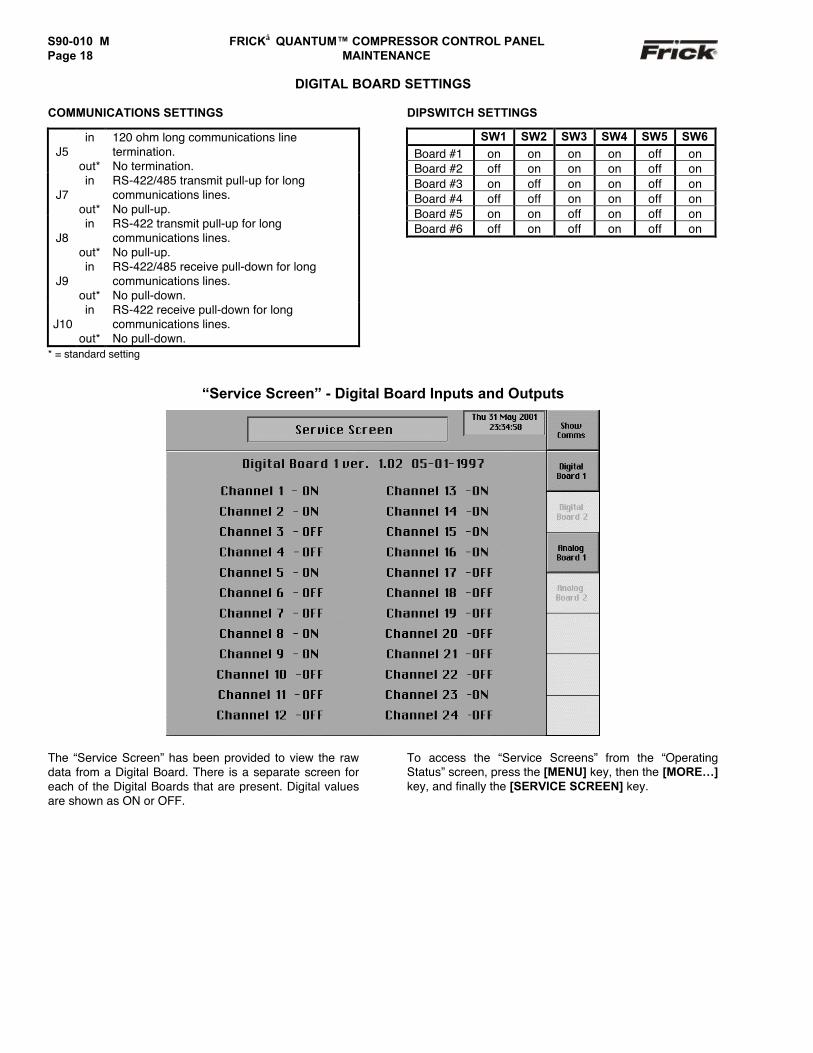
DIGITAL BOARD SETTINGS
COMMUNICATIONS SETTINGS
J5in
out*
120 ohm long communications linetermination.No termination.
J7in
out*
RS-422/485 transmit pull-up for longcommunications lines.No pull-up.
J8in
out*
RS-422 transmit pull-up for longcommunications lines.No pull-up.
J9in
out*
RS-422/485 receive pull-down for longcommunications lines.No pull-down.
J10in
out*
RS-422 receive pull-down for longcommunications lines.No pull-down.
* = standard setting
DIPSWITCH SETTINGS
SW1 SW2 SW3 SW4 SW5 SW6Board #1 on on on on off onBoard #2 off on on on off onBoard #3 on off on on off onBoard #4 off off on on off onBoard #5 on on off on off onBoard #6 off on off on off on
“Service Screen” - Digital Board Inputs and Outputs
The “Service Screen” has been provided to view the rawdata from a Digital Board. There is a separate screen foreach of the Digital Boards that are present. Digital valuesare shown as ON or OFF.
To access the “Service Screens” from the “OperatingStatus” screen, press the [MENU] key, then the [MORE…]key, and finally the [SERVICE SCREEN] key.
FRICK QUANTUM™ COMPRESSOR CONTROL PANEL S90-010 M MAINTENANCE Page 19
ANALOG BOARDS
The information that follows in this section can help locateproblems that can occur with Analog Input and Outputcircuit boards, and their interaction with the Quantum™controller.
Analog Board Description
The Analog Board is actually a small microprocessorboard and programmed to control analog outputs, oraccepting inputs, from external electrical devices. EachAnalog Board has the capability of 16 independentchannels or I/O (Input/Output). With the Quantum™Compressor Control, these I/O channels are dedicated,through the software and external wring, as to the functionof each channel. Each channel that is used by thesoftware will have to be configured for the type of devicethat is connected to it (4-20 mA, 0-5 v, 1-5 v or ICTD). Thestandard Quantum™ compressor control can have up totwo Analog Boards (depending on options).
Communications LED's
The Quantum™ controller is in constant communicationwith all Analog (and Digital) Boards. You will notice oneach Analog and Digital board, that there are a pair ofLED's that are labeled as RX and TX. These lettersrepresent Receive (RX) and Transmit (TX). These LED'sshould be flashing at a fairly high rate during normaloperation. This indicates that the Quantum™, and theboard that you are looking at, are properly communicatingwith each other.
• Reference the “JUMPER AND DIPSWITCHSETTINGS” section later in this section. Thissection contains the dipswitch settings foraddressing the Analog I/O Board numbers (1)through (6), although only the first two boardscan be addressed. When these switches areproperly set, the Quantum™ is able to seriallycommunicate with each I/O board and providecontrol signals and data exchange. If theseswitches are not properly set, the result will beone of the following:
• Lost or failed communications (displayed inthe “Communications Status” box on theHome screen)
• The wrong analog input signals beingreceived
• The wrong analog output signals being sentfrom the board.
Connections to the Quantum™
As stated earlier, the Quantum™ standard compressorcontrol system utilizes up to two Digital, and two AnalogBoards. To connect all of these boards together so thatthe Quantum™ can control them, they must beinterconnected with a wiring harness that provides all ofthe necessary D.C. voltage requirements, as well as thecommunications capabilities. A diagram of this wiringharness can be found later in this manual (see the PowerI/O Wiring Harness drawing). This harness has an 18 pinconnector at one end, that plugs into the Quantum™.Another connector plugs into the power supply. The
remaining four connectors (16 pin) will plug into each ofthe Digital and Analog Boards in the system (up to fourtotal).
Upon close examination of this harness, you will noticethat each of the connectors for both the Quantum™ andthe four I/O boards, have two rows of connections. Thewires that are inserted into the positions of one row, areinternally daisychained on each I/O board, to continue thevoltages and signals to the adjacent row. Therefore, anytime that a connector is unplugged from the daisychain,these voltages and signals cannot continue through to thenext board. Whenever a plug is not to be inserted onto aboard, either for servicing, or if not all boards are presentbecause of the options that are present, then a shuntingplug (refer to the Recommended Spare Parts list) must beinstalled onto the open connector.
The four wires that feed from the power supply to theQuantum™ provide all of the necessary D.C. voltage thatis required (+5 Vdc, -12 Vdc, +12 Vdc, and Return orCommon). The voltages are passed through the connectoron the Quantum™, and two new signals are generated bythe Quantum™ to be passed on through the daisychain tothe I/O boards. These two signals are the RX (receive)and TX (transmit). These signals are the means by whichthe Quantum™ communicates to the I/O.
The Analog Boards require the +5 Vdc for logic, the-12 Vdc for internal voltage reference, and +12 Vdc forexternal sensors (plus or +) and the Return (common or -).The communications signals (RX & TX) are required by allboards.
Logic Voltage (Power) LED
Located on the Analog Board is a “Power” LED. This LEDwill be illuminated as long as the “Control Power” switch isON, and the proper voltage is present at the Quantum™power supply. The power supply generates the +5 Vdcvoltage, and passes it on through the Power-I/O harness.This LED does not indicate however that the propervoltage is necessarily present at the board, only that thevoltage is enough to energize the voltage sensing circuitry.If a voltage related problem is suspected with regard to anAnalog Board, the only way to actually determine this is toread the voltage on a DVM. This may be accomplished bylocating the white power/communications connector on theboard. Notice that the Analog Board has only one of theseconnectors. The associated power/communicationsharness plugs in to it. Take the red (positive) probe of theDVM and carefully insert the end into the “+5V” lead, andthe black (negative) probe end into the “RET” (Return orCommon) lead, as shown below:
+5V
RET
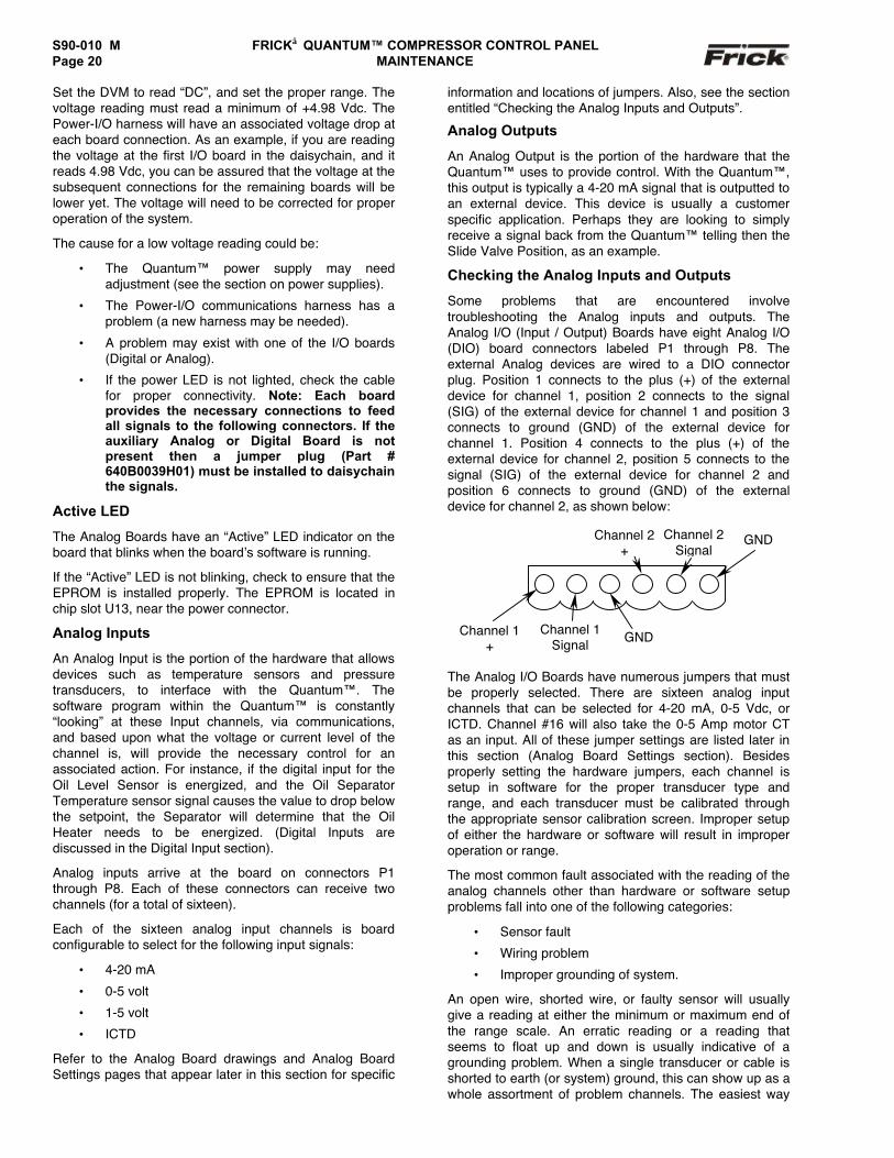
S90-010 M FRICK QUANTUM™ COMPRESSOR CONTROL PANELPage 20 MAINTENANCE
Set the DVM to read “DC”, and set the proper range. Thevoltage reading must read a minimum of +4.98 Vdc. ThePower-I/O harness will have an associated voltage drop ateach board connection. As an example, if you are readingthe voltage at the first I/O board in the daisychain, and itreads 4.98 Vdc, you can be assured that the voltage at thesubsequent connections for the remaining boards will belower yet. The voltage will need to be corrected for properoperation of the system.
The cause for a low voltage reading could be:
• The Quantum™ power supply may needadjustment (see the section on power supplies).
• The Power-I/O communications harness has aproblem (a new harness may be needed).
• A problem may exist with one of the I/O boards(Digital or Analog).
• If the power LED is not lighted, check the cablefor proper connectivity. Note: Each boardprovides the necessary connections to feedall signals to the following connectors. If theauxiliary Analog or Digital Board is notpresent then a jumper plug (Part #640B0039H01) must be installed to daisychainthe signals.
Active LED
The Analog Boards have an “Active” LED indicator on theboard that blinks when the board’s software is running.
If the “Active” LED is not blinking, check to ensure that theEPROM is installed properly. The EPROM is located inchip slot U13, near the power connector.
Analog Inputs
An Analog Input is the portion of the hardware that allowsdevices such as temperature sensors and pressuretransducers, to interface with the Quantum™. Thesoftware program within the Quantum™ is constantly“looking” at these Input channels, via communications,and based upon what the voltage or current level of thechannel is, will provide the necessary control for anassociated action. For instance, if the digital input for theOil Level Sensor is energized, and the Oil SeparatorTemperature sensor signal causes the value to drop belowthe setpoint, the Separator will determine that the OilHeater needs to be energized. (Digital Inputs arediscussed in the Digital Input section).
Analog inputs arrive at the board on connectors P1through P8. Each of these connectors can receive twochannels (for a total of sixteen).
Each of the sixteen analog input channels is boardconfigurable to select for the following input signals:
• 4-20 mA
• 0-5 volt
• 1-5 volt
• ICTD
Refer to the Analog Board drawings and Analog BoardSettings pages that appear later in this section for specific
information and locations of jumpers. Also, see the sectionentitled “Checking the Analog Inputs and Outputs”.
Analog Outputs
An Analog Output is the portion of the hardware that theQuantum™ uses to provide control. With the Quantum™,this output is typically a 4-20 mA signal that is outputted toan external device. This device is usually a customerspecific application. Perhaps they are looking to simplyreceive a signal back from the Quantum™ telling then theSlide Valve Position, as an example.
Checking the Analog Inputs and Outputs
Some problems that are encountered involvetroubleshooting the Analog inputs and outputs. TheAnalog I/O (Input / Output) Boards have eight Analog I/O(DIO) board connectors labeled P1 through P8. Theexternal Analog devices are wired to a DIO connectorplug. Position 1 connects to the plus (+) of the externaldevice for channel 1, position 2 connects to the signal(SIG) of the external device for channel 1 and position 3connects to ground (GND) of the external device forchannel 1. Position 4 connects to the plus (+) of theexternal device for channel 2, position 5 connects to thesignal (SIG) of the external device for channel 2 andposition 6 connects to ground (GND) of the externaldevice for channel 2, as shown below:
The Analog I/O Boards have numerous jumpers that mustbe properly selected. There are sixteen analog inputchannels that can be selected for 4-20 mA, 0-5 Vdc, orICTD. Channel #16 will also take the 0-5 Amp motor CTas an input. All of these jumper settings are listed later inthis section (Analog Board Settings section). Besidesproperly setting the hardware jumpers, each channel issetup in software for the proper transducer type andrange, and each transducer must be calibrated throughthe appropriate sensor calibration screen. Improper setupof either the hardware or software will result in improperoperation or range.
The most common fault associated with the reading of theanalog channels other than hardware or software setupproblems fall into one of the following categories:
• Sensor fault
• Wiring problem
• Improper grounding of system.
An open wire, shorted wire, or faulty sensor will usuallygive a reading at either the minimum or maximum end ofthe range scale. An erratic reading or a reading thatseems to float up and down is usually indicative of agrounding problem. When a single transducer or cable isshorted to earth (or system) ground, this can show up as awhole assortment of problem channels. The easiest way
GND
Channel 2+
Channel 1+
Channel 1Signal
Channel 2Signal
GND
FRICK QUANTUM™ COMPRESSOR CONTROL PANEL S90-010 M MAINTENANCE Page 21
to find a short to earth problem is to disconnect all thesensor plugs and ohm out each plug screw terminal toearth for open (infinite) impedance. All sensors shouldread open to earth with the exception of the CT motorcurrent channel. One side of the CT is grounded in theMotor Control Center (MCC). (The third pin on pressuresensors is ground.)
Replacing a Defective Analog Board
The procedure to replace an Analog board is outlinedbelow:
1. Shut off control power.
2. Remove the old board from the machine and thenew board from its packing and place both on ananti-static surface.
3. Remove any required chip(s) from the defectiveboard and install them in the replacement board.
4. Check that all jumpers, dipswitches andcomponents are properly setup on the new boardas it was on the old board.
5. Install the modified replacement board in thepanel.
Adding Analog Board 2
The procedure to add Analog Board 2 is outlined below:
1. Remove the new board from its packing andplace it on an antistatic surface.
2. Make sure the board’s dipswitch ID has been setproperly.
3. Check that all jumpers and components aresetup properly (refer to the Analog Settingstables at the end of this section).
4. Shut off control power.
5. Install the new board in the panel. See theControl Center Assembly (refer to theQUANTUM™ DRAWINGS list for drawingnumber) for proper mounting location of theboard.
6. To prevent possible noise problems fromimproper wiring:
• When routing wiring to the terminal strip,keep as much separation as possiblebetween the Analog boards wiring and theAC control wiring of the Digital I/O boards.
• DO NOT run any AC lines parallel to sensorlines!!
• All DC analog wiring is to enter the panel onthe left side. All AC digital wiring is to enteron the right side of the panel.
After replacing or installing an Analog Board and poweringon the control panel, select [Detect I/O Boards] from the“Change Communications” screen in Panel Setup (thissection appears later in this manual). This selectionprovides a method to detect all connected Analog andDigital boards. If a board has been removed, acommunication error shutdown will be issued until this keyis selected. The “About” screen will show what wasdetected.
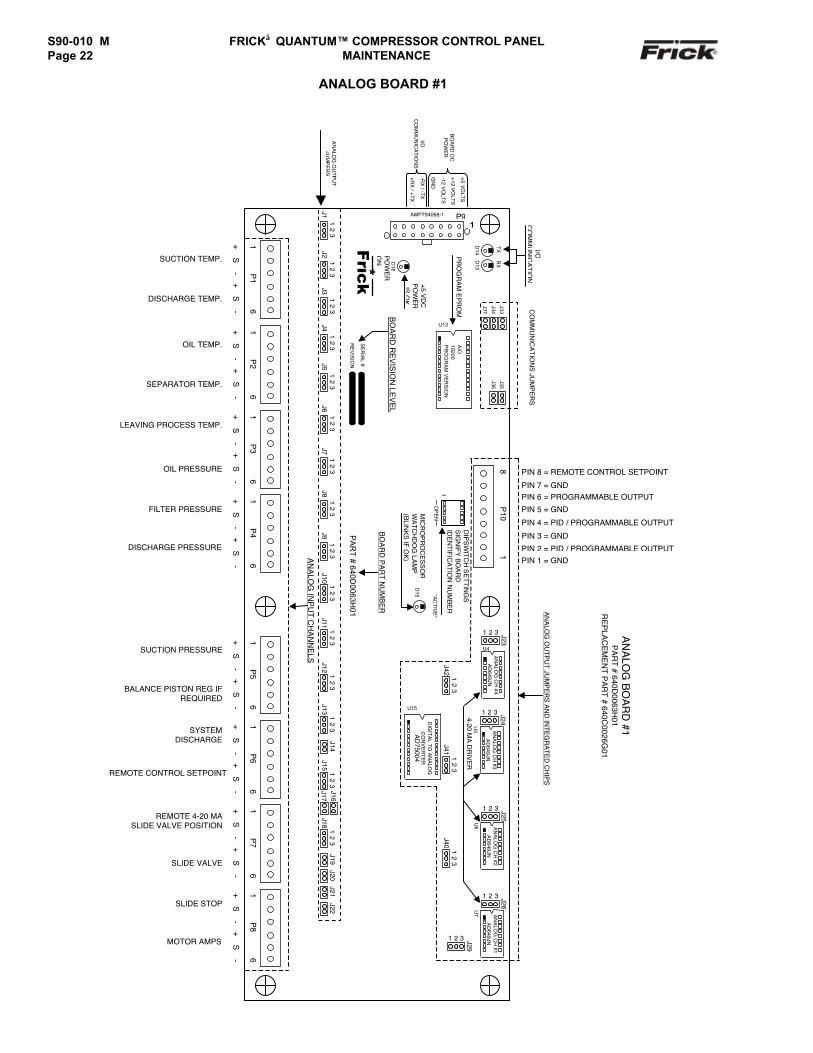
S90-010 M FRICK QUANTUM™ COMPRESSOR CONTROL PANELPage 22 MAINTENANCE
ANALOG BOARD #1
PIN 8 = REMOTE CONTROL SETPOINT
PIN 7 = GNDPIN 6 = PROGRAMMABLE OUTPUT
PIN 5 = GND
PIN 4 = PID / PROGRAMMABLE OUTPUT
PIN 3 = GND
PIN 2 = PID / PROGRAMMABLE OUTPUTPIN 1 = GND
U7
+5 VO
LTS
+12 VO
LTS
-12 VO
LTS
GN
D
-RX
/ -TX
+RX
/ +TX
S
16
P5
AN
ALO
G IN
PU
T CH
AN
NE
LS
+S
-+
S-
+S
-+
S-
+S
-+
S-
+S
-+
S-
+S
-+
S-
+S
-+
-
16
P1
16
P2
16
P3
D16
PR
OG
RA
M E
PR
OM
Frick*
PO
WE
RO
N
+5 VD
CP
OW
ER
IS O
K
J11
23
J21
23
J31
23
J41
23
J51
23
J61
23
J71
23
J81
23
J91
23
J101
23
J111
23
J121
23
J131
23
J14J15
12
3J17
J181
23
J19J20
J21J22
J16
P9AMP794068-1
1
D14
TX
D13
RX
I/OC
OM
MU
NIC
ATIO
N
BO
AR
D D
CP
OW
ER
I/OC
OM
MU
NIC
AT
ION
S
CO
MM
UN
ICA
TION
S JU
MP
ER
S
SE
RIA
L #
RE
VIS
ION
AIO
19200P
RO
GR
AM
VE
RS
ION
U13
BO
AR
D R
EV
ISIO
N LE
VE
L
AN
ALO
G B
OA
RD
#1P
AR
T # 640D0063H
01R
EP
LAC
EM
EN
T PA
RT # 640C
0026G01
AN
ALO
G O
UTP
UT JU
MP
ER
S A
ND
INTE
GR
ATE
D C
HIP
S
16
P4
16
P6
PA
RT
# 640D0063H
01
BO
AR
D P
AR
T NU
MB
ER
SUCTION TEMP.
DISCHARGE TEMP.
OIL TEMP.
SEPARATOR TEMP.
LEAVING PROCESS TEMP.
OIL PRESSURE
FILTER PRESSURE
DISCHARGE PRESSURE
SUCTION PRESSURE
BALANCE PISTON REG IFREQUIRED
SYSTEMDISCHARGE
REMOTE CONTROL SETPOINT
REMOTE 4-20 MASLIDE VALVE POSITION
16
P7
SLIDE VALVE
+S
-+
S-
SLIDE STOP
16
P8
MOTOR AMPS
+S
-+
S-
D15 "A
CTIV
E"
MIC
RO
PR
OC
ES
SO
RW
ATC
HD
OG
LAM
P(B
LINK
S IF O
K)
1O
PE
N
DIP
SW
ITCH
SE
TTING
SS
IGN
IFY B
OA
RD
IDE
NTIFIC
ATIO
N N
UM
BE
R
81
P10
DIG
ITA
L TO
AN
ALO
GC
ON
VE
RTE
RA
D75004
U15
J421
23
J23
1 2 3
AN
ALO
G C
H #4
AD
649JN
U4
J24
1 2 3
AN
ALO
G C
H #3
AD
649JN
U5
J411
23
J25
1 2 3
AN
ALO
G C
H #2
AD
649JN
U6
J26
1 2 3
AN
ALO
G C
H #1
AD
649JN
J401
23
J29
1 2 3
4-20 MA
DR
IVE
R
AN
ALO
G O
UT
PU
TJU
MP
ER
S
J33
J34
J37
J35
J36
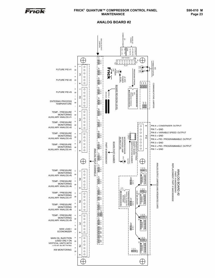
FRICK QUANTUM™ COMPRESSOR CONTROL PANEL S90-010 M MAINTENANCE Page 23
ANALOG BOARD #2
PIN 8 = CONDENSER OUTPUT
PIN 7 = GND
PIN 6 = VARIABLE SPEED OUTPUTPIN 5 = GND
PIN 4 = PID / PROGRAMMABLE OUTPUT
PIN 3 = GND
PIN 2 = PID / PROGRAMMABLE OUTPUTPIN 1 = GND
U7
+5 VO
LTS
+12 VO
LTS
-12 VO
LTS
GN
D
-RX
/ -TX
+RX
/ +TX
S
16
P5
AN
ALO
G IN
PU
T CH
AN
NE
LS
+S
-+
S-
+S
-+
S-
+S
-+
S-
+S
-+
S-
+S
-+
S-
+S
-+
-
16
P1
16
P2
16
P3
D16
PR
OG
RA
M E
PR
OM
Frick*
PO
WE
RO
N
+5 VD
CP
OW
ER
IS O
K
J11
23
J21
23
J31
23
J41
23
J51
23
J61
23
J71
23
J81
23
J91
23
J101
23
J111
23
J121
23
J131
23
J14J15
12
3J17
J181
23
J19J20
J21J22
J16
P9AMP794068-1
1
D14
TX
D13
RX
I/OC
OM
MU
NIC
ATIO
N
BO
AR
D D
CP
OW
ER
I/OC
OM
MU
NIC
AT
ION
S
CO
MM
UN
ICA
TION
S JU
MP
ER
S
SE
RIA
L #
RE
VIS
ION
AIO
19200P
RO
GR
AM
VE
RS
ION
U13
BO
AR
D R
EV
ISIO
N LE
VE
L
AN
ALO
G B
OA
RD
#2P
AR
T # 640D0063H
01R
EP
LAC
EM
EN
T PA
RT # 640C
0026G02
AN
ALO
G O
UTP
UT JU
MP
ER
S A
ND
INTE
GR
ATE
D C
HIP
S
16
P4
16
P6
PA
RT
# 640D0063H
01
BO
AR
D P
AR
T NU
MB
ER
FUTURE PID #1
FUTURE PID #2
FUTURE PID #3
ENTERING PROCESSTEMPERATURE
TEMP. / PRESSUREMONITORING
AUXILIARY ANALOG #1
TEMP. / PRESSUREMONITORING
AUXILIARY ANALOG #2
TEMP. / PRESSUREMONITORING
AUXILIARY ANALOG #3
TEMP. / PRESSUREMONITORING
AUXILIARY ANALOG #4
TEMP. / PRESSUREMONITORING
AUXILIARY ANALOG #5
TEMP. / PRESSUREMONITORING
AUXILIARY ANALOG #6
TEMP. / PRESSUREMONITORING
AUXILIARY ANALOG #7
TEMP. / PRESSUREMONITORING
AUXILIARY ANALOG #8
TEMP. / PRESSUREMONITORING
AUXILIARY ANALOG #9
16
P7
SIDE LOAD /ECONOMIZER
+S
-+
S-
MAIN OIL INJECTION(USED ONLY ON
VERTICAL UNITS WITHLIQUID INJECTION)
16
P8
KW MONITORING
+S
-+
S-
D15 "A
CTIV
E"
MIC
RO
PR
OC
ES
SO
RW
ATC
HD
OG
LAM
P(B
LINK
S IF O
K)
1O
PE
N
DIP
SW
ITCH
SE
TTING
SS
IGN
IFY B
OA
RD
IDE
NTIFIC
ATIO
N N
UM
BE
R
81
P10
DIG
ITA
L TO
AN
ALO
GC
ON
VE
RTE
RA
D75004
U15
J421
23
J23
1 2 3
AN
ALO
G C
H #4
AD
649JN
U4
J24
1 2 3
AN
ALO
G C
H #3
AD
649JN
U5
J411
23
J25
1 2 3
AN
ALO
G C
H #2
AD
649JN
U6
J26
1 2 3
AN
ALO
G C
H #1
AD
649JN
J401
23
J29
1 2 3
4-20 MA
DR
IVE
R
AN
ALO
G O
UT
PU
TJU
MP
ER
S
J33
J34
J37
J35
J36
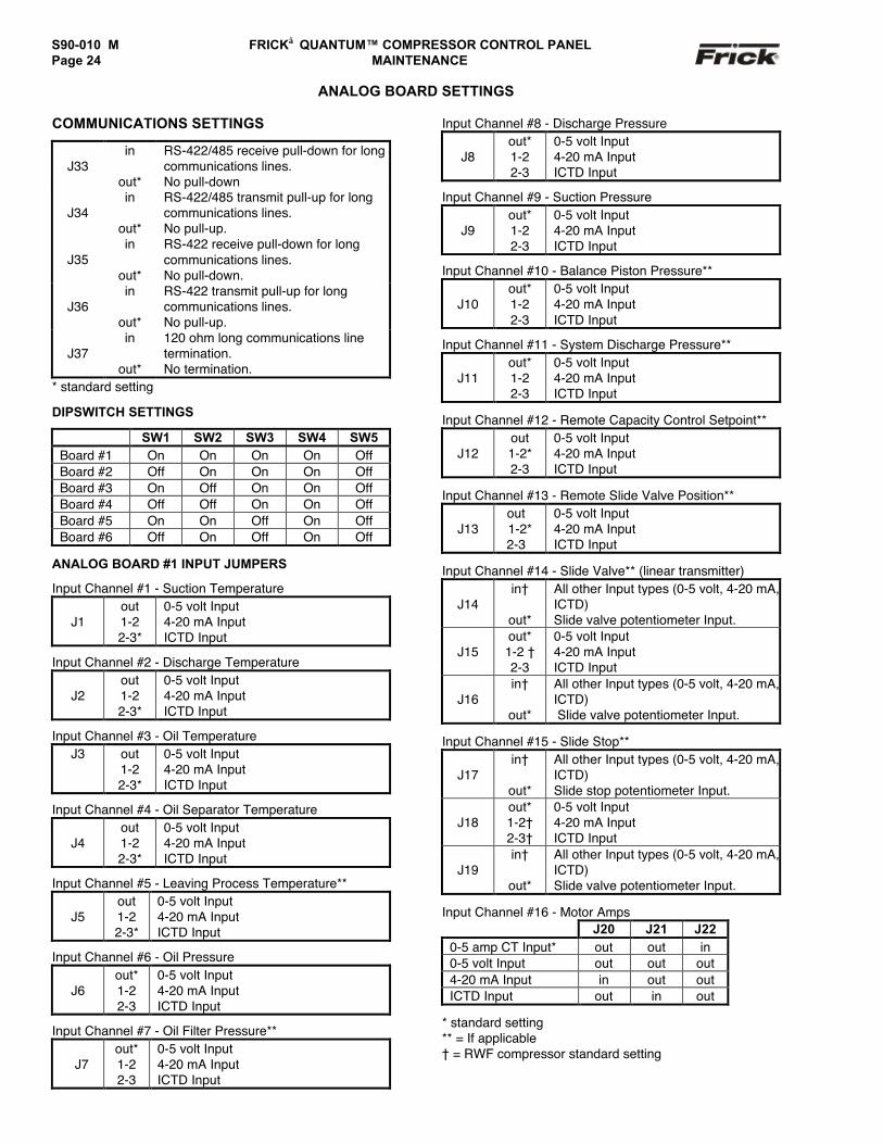
S90-010 M FRICK QUANTUM™ COMPRESSOR CONTROL PANELPage 24 MAINTENANCE
ANALOG BOARD SETTINGS
COMMUNICATIONS SETTINGS
J33in
out*
RS-422/485 receive pull-down for longcommunications lines.No pull-down
J34in
out*
RS-422/485 transmit pull-up for longcommunications lines.No pull-up.
J35in
out*
RS-422 receive pull-down for longcommunications lines.No pull-down.
J36in
out*
RS-422 transmit pull-up for longcommunications lines.No pull-up.
J37in
out*
120 ohm long communications linetermination.No termination.
* standard setting
DIPSWITCH SETTINGS
SW1 SW2 SW3 SW4 SW5Board #1 On On On On OffBoard #2 Off On On On OffBoard #3 On Off On On OffBoard #4 Off Off On On OffBoard #5 On On Off On OffBoard #6 Off On Off On Off
ANALOG BOARD #1 INPUT JUMPERS
Input Channel #1 - Suction Temperature
J1out1-22-3*
0-5 volt Input4-20 mA InputICTD Input
Input Channel #2 - Discharge Temperature
J2out1-22-3*
0-5 volt Input4-20 mA InputICTD Input
Input Channel #3 - Oil TemperatureJ3 out
1-22-3*
0-5 volt Input4-20 mA InputICTD Input
Input Channel #4 - Oil Separator Temperature
J4out1-22-3*
0-5 volt Input4-20 mA InputICTD Input
Input Channel #5 - Leaving Process Temperature**
J5out1-22-3*
0-5 volt Input4-20 mA InputICTD Input
Input Channel #6 - Oil Pressure
J6out*1-22-3
0-5 volt Input4-20 mA InputICTD Input
Input Channel #7 - Oil Filter Pressure**
J7out*1-22-3
0-5 volt Input4-20 mA InputICTD Input
Input Channel #8 - Discharge Pressure
J8out*1-22-3
0-5 volt Input4-20 mA InputICTD Input
Input Channel #9 - Suction Pressure
J9out*1-22-3
0-5 volt Input4-20 mA InputICTD Input
Input Channel #10 - Balance Piston Pressure**
J10out*1-22-3
0-5 volt Input4-20 mA InputICTD Input
Input Channel #11 - System Discharge Pressure**
J11out*1-22-3
0-5 volt Input4-20 mA InputICTD Input
Input Channel #12 - Remote Capacity Control Setpoint**
J12out1-2*2-3
0-5 volt Input4-20 mA InputICTD Input
Input Channel #13 - Remote Slide Valve Position**
J13out1-2*2-3
0-5 volt Input4-20 mA InputICTD Input
Input Channel #14 - Slide Valve** (linear transmitter)
J14in†
out*
All other Input types (0-5 volt, 4-20 mA,ICTD)Slide valve potentiometer Input.
J15out*1-2 †2-3
0-5 volt Input4-20 mA InputICTD Input
J16in†
out*
All other Input types (0-5 volt, 4-20 mA,ICTD) Slide valve potentiometer Input.
Input Channel #15 - Slide Stop**
J17in†
out*
All other Input types (0-5 volt, 4-20 mA,ICTD)Slide stop potentiometer Input.
J18out*1-2†2-3†
0-5 volt Input4-20 mA InputICTD Input
J19in†
out*
All other Input types (0-5 volt, 4-20 mA,ICTD)Slide valve potentiometer Input.
Input Channel #16 - Motor AmpsJ20 J21 J22
0-5 amp CT Input* out out in0-5 volt Input out out out4-20 mA Input in out outICTD Input out in out
* standard setting** = If applicable† = RWF compressor standard setting
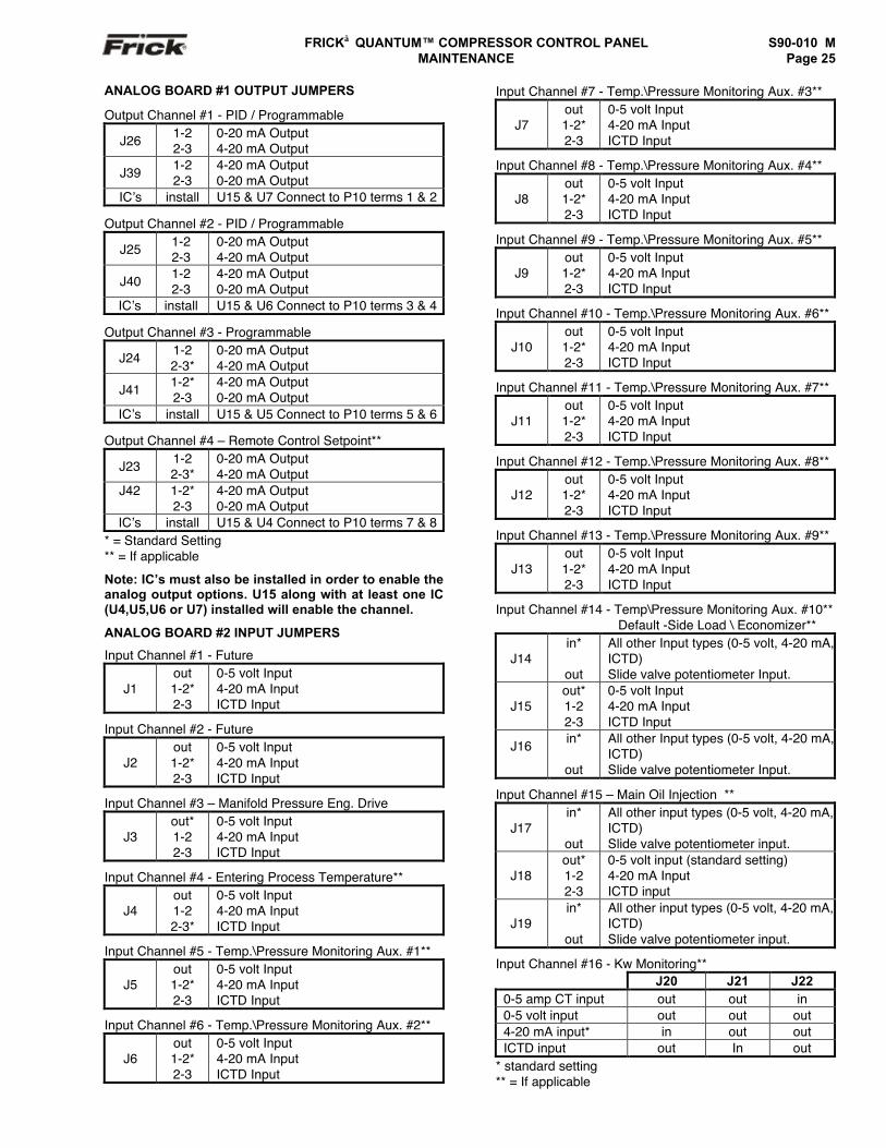
FRICK QUANTUM™ COMPRESSOR CONTROL PANEL S90-010 M MAINTENANCE Page 25
ANALOG BOARD #1 OUTPUT JUMPERS
Output Channel #1 - PID / Programmable
J26 1-22-3
0-20 mA Output4-20 mA Output
J39 1-22-3
4-20 mA Output0-20 mA Output
IC’s install U15 & U7 Connect to P10 terms 1 & 2
Output Channel #2 - PID / Programmable
J25 1-22-3
0-20 mA Output4-20 mA Output
J40 1-22-3
4-20 mA Output0-20 mA Output
IC’s install U15 & U6 Connect to P10 terms 3 & 4
Output Channel #3 - Programmable
J24 1-22-3*
0-20 mA Output4-20 mA Output
J41 1-2*2-3
4-20 mA Output0-20 mA Output
IC’s install U15 & U5 Connect to P10 terms 5 & 6
Output Channel #4 – Remote Control Setpoint**
J23 1-22-3*
0-20 mA Output4-20 mA Output
J42 1-2*2-3
4-20 mA Output0-20 mA Output
IC’s install U15 & U4 Connect to P10 terms 7 & 8* = Standard Setting** = If applicable
Note: IC’s must also be installed in order to enable theanalog output options. U15 along with at least one IC(U4,U5,U6 or U7) installed will enable the channel.
ANALOG BOARD #2 INPUT JUMPERS
Input Channel #1 - Future
J1out1-2*2-3
0-5 volt Input4-20 mA InputICTD Input
Input Channel #2 - Future
J2out1-2*2-3
0-5 volt Input4-20 mA InputICTD Input
Input Channel #3 – Manifold Pressure Eng. Drive
J3out*1-22-3
0-5 volt Input4-20 mA InputICTD Input
Input Channel #4 - Entering Process Temperature**
J4out1-22-3*
0-5 volt Input4-20 mA InputICTD Input
Input Channel #5 - Temp.\Pressure Monitoring Aux. #1**
J5out1-2*2-3
0-5 volt Input4-20 mA InputICTD Input
Input Channel #6 - Temp.\Pressure Monitoring Aux. #2**
J6out1-2*2-3
0-5 volt Input4-20 mA InputICTD Input
Input Channel #7 - Temp.\Pressure Monitoring Aux. #3**
J7out1-2*2-3
0-5 volt Input4-20 mA InputICTD Input
Input Channel #8 - Temp.\Pressure Monitoring Aux. #4**
J8out1-2*2-3
0-5 volt Input4-20 mA InputICTD Input
Input Channel #9 - Temp.\Pressure Monitoring Aux. #5**
J9out1-2*2-3
0-5 volt Input4-20 mA InputICTD Input
Input Channel #10 - Temp.\Pressure Monitoring Aux. #6**
J10out1-2*2-3
0-5 volt Input4-20 mA InputICTD Input
Input Channel #11 - Temp.\Pressure Monitoring Aux. #7**
J11out1-2*2-3
0-5 volt Input4-20 mA InputICTD Input
Input Channel #12 - Temp.\Pressure Monitoring Aux. #8**
J12out1-2*2-3
0-5 volt Input4-20 mA InputICTD Input
Input Channel #13 - Temp.\Pressure Monitoring Aux. #9**
J13out1-2*2-3
0-5 volt Input4-20 mA InputICTD Input
Input Channel #14 - Temp\Pressure Monitoring Aux. #10** Default -Side Load \ Economizer**
J14in*
out
All other Input types (0-5 volt, 4-20 mA,ICTD)Slide valve potentiometer Input.
J15out*1-22-3
0-5 volt Input4-20 mA InputICTD Input
J16 in*
out
All other Input types (0-5 volt, 4-20 mA,ICTD)Slide valve potentiometer Input.
Input Channel #15 – Main Oil Injection **
J17in*
out
All other input types (0-5 volt, 4-20 mA,ICTD)Slide valve potentiometer input.
J18out*1-22-3
0-5 volt input (standard setting)4-20 mA InputICTD input
J19in*
out
All other input types (0-5 volt, 4-20 mA,ICTD)Slide valve potentiometer input.
Input Channel #16 - Kw Monitoring**J20 J21 J22
0-5 amp CT input out out in0-5 volt input out out out4-20 mA input* in out outICTD input out In out
* standard setting** = If applicable
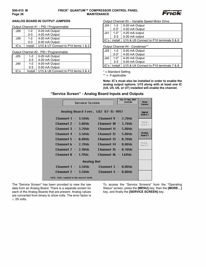
S90-010 M FRICK QUANTUM™ COMPRESSOR CONTROL PANELPage 26 MAINTENANCE
ANALOG BOARD #2 OUTPUT JUMPERS
Output Channel #1 – PID / ProgrammableJ26 1-2
2-30-20 mA Output4-20 mA Output
J39 1-22-3
4-20 mA Output0-20 mA Output
IC’s install U15 & U7 Connect to P10 terms 1 & 2
Output Channel #2 - PID / ProgrammableJ25 1-2
2-30-20 mA Output4-20 mA Output
J40 1-22-3
4-20 mA Output0-20 mA Output
IC’s Install U15 & U6 Connect to P10 terms 3 & 4
Output Channel #3 – Variable Speed Motor DriveJ24 1-2
2-3*0-20 mA Output4-20 mA Output
J41 1-2*2-3
4-20 mA output0-20 mA output
IC’s install U15 & U5 Connect to P10 terminals 5 & 6
Output Channel #4 - Condenser**J23 1-2
2-3*0-20 mA Output4-20 mA Output
J42 1-2*2-3
4-20 mA Output0-20 mA Output
IC’s Install U15 & U4 Connect to P10 terminals 7 & 8
* = Standard Setting** = If applicable
Note: IC’s must also be installed in order to enable theanalog output options. U15 along with at least one IC(U4, U5, U6, or U7) installed will enable the channel.
“Service Screen” - Analog Board Inputs and Outputs
The “Service Screen” has been provided to view the rawdata from an Analog Board. There is a separate screen foreach of the Analog Boards that are present. Analog valuesare converted from binary to show volts. The error factor is± .05 volts.
To access the “Service Screens” from the “OperatingStatus” screen, press the [MENU] key, then the [MORE…]key, and finally the [SERVICE SCREEN] key.
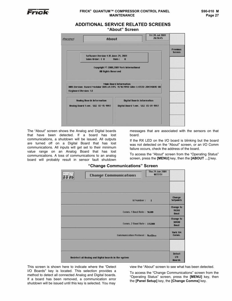
FRICK QUANTUM™ COMPRESSOR CONTROL PANEL S90-010 M MAINTENANCE Page 27
ADDITIONAL SERVICE RELATED SCREENS“About” Screen
The “About” screen shows the Analog and Digital boardsthat have been detected. If a board has lostcommunications, a shutdown will be issued. All outputsare turned off on a Digital Board that has lostcommunications. All inputs will get set to their minimumvalue range on an Analog Board that has lostcommunications. A loss of communications to an analogboard will probably result in sensor fault shutdown
messages that are associated with the sensors on thatboard.
If the RX LED on the I/O board is blinking but the boardwas not detected on the “About” screen, or an I/O Commfailure occurs, check the address of the board.
To access the “About” screen from the “Operating Status”screen, press the [MENU] key, then the [ABOUT …] key.
“Change Communications” Screen
This screen is shown here to indicate where the “DetectI/O Boards” key is located. This selection provides amethod to detect all connected Analog and Digital boards.If a board has been removed, a communication errorshutdown will be issued until this key is selected. You may
view the “About” screen to see what has been detected.
To access the “Change Communications” screen from the“Operating Status” screen, press the [MENU] key, thenthe [Panel Setup] key, the [Change Comms] key.
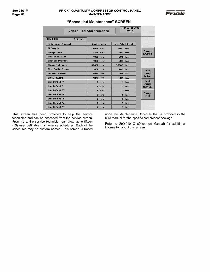
S90-010 M FRICK QUANTUM™ COMPRESSOR CONTROL PANELPage 28 MAINTENANCE
“Scheduled Maintenance” SCREEN
This screen has been provided to help the servicetechnician and can be accessed from the service screen.From here, the service technician can view up to fifteen(15) user definable maintenance schedules. Each of theschedules may be custom named. This screen is based
upon the Maintenance Schedule that is provided in theIOM manual for the specific compressor package.
Refer to S90-010 O (Operation Manual) for additionalinformation about this screen.
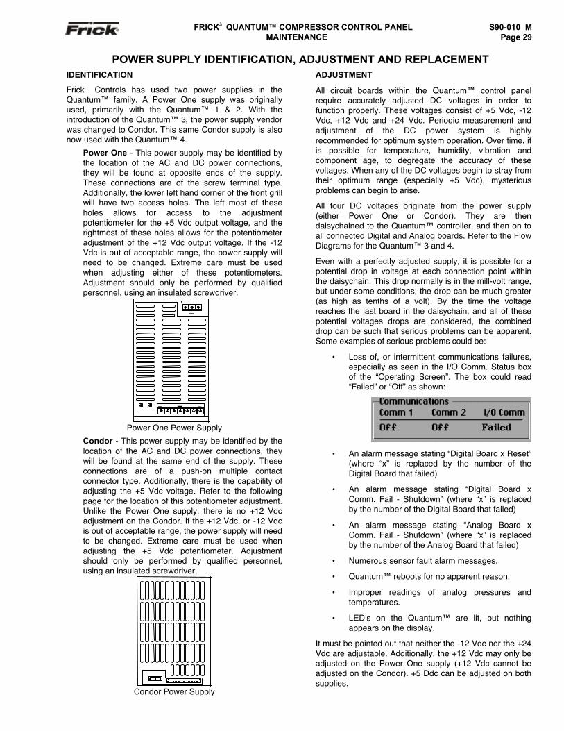
FRICK QUANTUM™ COMPRESSOR CONTROL PANEL S90-010 M MAINTENANCE Page 29
POWER SUPPLY IDENTIFICATION, ADJUSTMENT AND REPLACEMENTIDENTIFICATION
Frick Controls has used two power supplies in theQuantum™ family. A Power One supply was originallyused, primarily with the Quantum™ 1 & 2. With theintroduction of the Quantum™ 3, the power supply vendorwas changed to Condor. This same Condor supply is alsonow used with the Quantum™ 4.
Power One - This power supply may be identified bythe location of the AC and DC power connections,they will be found at opposite ends of the supply.These connections are of the screw terminal type.Additionally, the lower left hand corner of the front grillwill have two access holes. The left most of theseholes allows for access to the adjustmentpotentiometer for the +5 Vdc output voltage, and therightmost of these holes allows for the potentiometeradjustment of the +12 Vdc output voltage. If the -12Vdc is out of acceptable range, the power supply willneed to be changed. Extreme care must be usedwhen adjusting either of these potentiometers.Adjustment should only be performed by qualifiedpersonnel, using an insulated screwdriver.
Power One Power Supply
Condor - This power supply may be identified by thelocation of the AC and DC power connections, theywill be found at the same end of the supply. Theseconnections are of a push-on multiple contactconnector type. Additionally, there is the capability ofadjusting the +5 Vdc voltage. Refer to the followingpage for the location of this potentiometer adjustment.Unlike the Power One supply, there is no +12 Vdcadjustment on the Condor. If the +12 Vdc, or -12 Vdcis out of acceptable range, the power supply will needto be changed. Extreme care must be used whenadjusting the +5 Vdc potentiometer. Adjustmentshould only be performed by qualified personnel,using an insulated screwdriver.
Condor Power Supply
ADJUSTMENT
All circuit boards within the Quantum™ control panelrequire accurately adjusted DC voltages in order tofunction properly. These voltages consist of +5 Vdc, -12Vdc, +12 Vdc and +24 Vdc. Periodic measurement andadjustment of the DC power system is highlyrecommended for optimum system operation. Over time, itis possible for temperature, humidity, vibration andcomponent age, to degregate the accuracy of thesevoltages. When any of the DC voltages begin to stray fromtheir optimum range (especially +5 Vdc), mysteriousproblems can begin to arise.
All four DC voltages originate from the power supply(either Power One or Condor). They are thendaisychained to the Quantum™ controller, and then on toall connected Digital and Analog boards. Refer to the FlowDiagrams for the Quantum™ 3 and 4.
Even with a perfectly adjusted supply, it is possible for apotential drop in voltage at each connection point withinthe daisychain. This drop normally is in the mill-volt range,but under some conditions, the drop can be much greater(as high as tenths of a volt). By the time the voltagereaches the last board in the daisychain, and all of thesepotential voltages drops are considered, the combineddrop can be such that serious problems can be apparent.Some examples of serious problems could be:
• Loss of, or intermittent communications failures,especially as seen in the I/O Comm. Status boxof the “Operating Screen”. The box could read“Failed” or “Off” as shown:
• An alarm message stating “Digital Board x Reset”(where “x” is replaced by the number of theDigital Board that failed)
• An alarm message stating “Digital Board xComm. Fail - Shutdown” (where “x” is replacedby the number of the Digital Board that failed)
• An alarm message stating “Analog Board xComm. Fail - Shutdown” (where “x” is replacedby the number of the Analog Board that failed)
• Numerous sensor fault alarm messages.
• Quantum™ reboots for no apparent reason.
• Improper readings of analog pressures andtemperatures.
• LED's on the Quantum™ are lit, but nothingappears on the display.
It must be pointed out that neither the -12 Vdc nor the +24Vdc are adjustable. Additionally, the +12 Vdc may only beadjusted on the Power One supply (+12 Vdc cannot beadjusted on the Condor). +5 Ddc can be adjusted on bothsupplies.
T
3
PTP
1
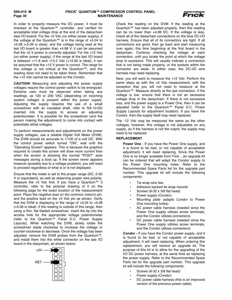
S90-010 M FRICK QUANTUM™ COMPRESSOR CONTROL PANELPage 30 MAINTENANCE
In order to properly measure the DC power, it must bechecked at the Quantum™ controller, and verified foracceptable total voltage drop at the end of the daisychain(last I/O board). For the +5 Vdc (on either power supply), ifthe voltage at the Quantum™ is in the range of +5.04 to+5.08 (+5.06 is ideal), and the voltage being read at thelast I/O board is greater than +4.98 V, it can be assumedthat the +5 V power is correctly adjusted. For the +12 Vdc(on either power supply), if the range at the last I/O boardis between +11.8 and +12.2 Vdc (+12.00 is ideal), it canbe assumed that the +12 V power is correct. The range forthis voltage is not critical at the Quantum™, and thereading does not need to be taken there. Remember thatthe +12 Vdc cannot be adjusted on the Condor.
CAUTION! Measuring and adjusting the power supplyvoltages require the control power switch to be energized.Extreme care must be observed when taking anyreadings, as 120 or 230 VAC (depending on incomingsystem voltage) is present within the power supply.Adjusting the supply requires the use of a smallscrewdriver with an insulated shaft, refer to NS-10-02)inserted into the supply to access an adjustingpotentiometer. It is possible for the screwdriver (and theperson making the adjustment) to come into contact withpotentially lethal voltages.
To perform measurements and adjustments on the powersupply voltages, use a reliable Digital Volt Meter (DVM).The DVM should be accurate to 1/100 of a volt DC. Withthe control power switch turned "ON", wait until the"Operating Screen" appears. This is because the graphicsrequired to create this screen will draw more current thanwhen the screen is showing the normal "POST" stylemessages during a boot up. If the screen never appearshowever (possibly due to a voltage problem), you will needto proceed regardless of what is or is not displayed.
Ensure that the meter is set to the proper range (DC, 0-50V or equivalent), as well as observing proper wire polarity.Measure the +5 Vdc first. If you have a Quantum™ 3controller, refer to the pictorial drawing of it on thefollowing page for the exact location of the measurementpoint. Place the negative lead on the common (return) pin,and the positive lead on the +5 Vdc pin as shown. Verifythat the DVM is displaying in the range of +5.04 to +5.08(+5.06 is ideal). If the reading is outside of this range, thenusing a thin, flat bladed screwdriver, insert the tip into theaccess hole for the appropriate voltage potentiometer(refer to the Quantum™ Panel D.C. Power SupplyLayouts). While watching the DVM, slowly rotate thescrewdriver blade clockwise to increase the voltage orcounter-clockwise to decrease. Once the voltage has beenadjusted, remove the DVM probes from the Quantum™,and install them into the white connector on the last I/Oboard in the daisychain, as shown below:
Check the reading on the DVM. If the reading at theQuantum™ has been adjusted properly, then this readingcan be no lower than +4.98 DC. If the voltage is less,check all of the daisychain connections on the blue DC-I/Oharness. Ensure that all of its connectors are tight. If allconnections are good, then go back and start measuringover again, this time beginning at the first board in thedaisychain. Continue checking the voltage at eachconnection, until you locate the point at which the voltagedrop is excessive. This will usually indicate a connectionthat is not being made properly, or the sockets within theconnector are weak. In either case, the DC-I/O wireharness may need replacing.
Next, you will want to measure the +12 Vdc. Perform thesame steps as with the +5 Vdc measurement, with theexception that you will not need to measure at theQuantum™. Measure directly at the last connection. If thevoltage is low, ensure that there is not an excessivevoltage drop in the daisychain. If there is not excessiveloss, and the power supply is a Power One, then it can beadjusted (refer to the Quantum™ Panel D.C. PowerSupply Layouts for adjustment location). If you have theCondor, then the supply itself may need replaced.
The -12 Vdc may be measured the same as the othervoltages, however, this voltage is not adjustable on anysupply, so if the harness is not the culprit, the supply mayneed to be replaced.
REPLACEMENT
Power One - If you have the Power One supply, andit is found to be bad, or not capable of acceptableadjustment, it will need replacing. Since the PowerOne is no longer available from Frick, an upgrade kitcan be ordered that will adapt the Condor supply tothe Power One mounting holes. Refer to theRecommended Spare Parts list for the upgrade partnumber. This upgrade kit will include the followingcomponents:
• Tie wrap wire ties• Adhesive backed tie wrap mounts• Screws (6-32 x 3/8 flat head)• Power supply (Condor)• Mounting plate (adapts Condor to Power
One mounting holes)• AC power cable harness (needed since the
Power One supply utilizes screw terminals,and the Condor utilizes connectors)
• DC power cable harness (needed since thePower One supply utilizes screw terminals,and the Condor utilizes connectors)
Condor - If you have the Condor power supply, and itis found to be bad, or not capable of acceptableadjustment, it will need replacing. When ordering thisreplacement, you will receive an upgrade kit. Thepurpose of this kit is to allow for the upgrading of theI/O DC power harness, at the same time as replacingthe power supply. Refer to the Recommended SpareParts list for the upgrade part number. This upgradekit will include the following components:
• Screws (6-32 x 3/8 flat head)• Power supply (Condor)• DC power cable harness (this is an improved
version of the previous power cable)
+5V
RET
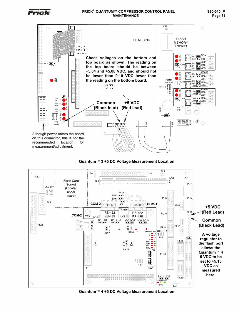
FRICK QUANTUM™ COMPRESSOR CONTROL PANEL S90-010 M MAINTENANCE Page 31
Quantum™ 3 +5 DC Voltage Measurement Location
Quantum™ 4 +5 DC Voltage Measurement Location
KB
COM2
TP3+5
TP4+12
TP5-12
RX
4TX
4
TP6GND
LK11
BA
LK10
BA
LK7
LK8
LK24B A
HEAT SINK
COM2RS232
LK19
FLASHMEMORYSOCKET
SW
BA
T1
SW
2
ON
1 2 3 4 5 6 7 8
LK20B A
P7
P7
TP1GND
COM31
2
3
4
RS-422RS-485
LK12LK11
LK13LK14LK15
TX3
RX
3
LK18B A
B A
1
2
3
4
RS-422RS-485
LK6
LK8LK9
LK10
LK7TX2
RX
2
LK17
COM1LK1LK2
LK3LK4LK5
1
2
3
4
RS-422RS-485
LK16B A
TX1
RX
1
LK25
-12V+5V
+12 +5 VDC(Red lead)
Common(Black lead)
Although power enters the boardon this connector, this is not therecommended location formeasurement/adjustment.
Check voltages on the bottom andtop board as shown. The reading onthe top board should be between+5.04 and +5.08 VDC, and should notbe lower than 0.10 VDC lower thanthe reading on the bottom board.
Check voltages on the bottom andtop board as shown. The reading onthe top board should be between+5.04 and +5.08 VDC, and should notbe lower than 0.10 VDC lower thanthe reading on the bottom board.
PL13
LK9
LK8LK10
PL16
PL8
PWR
SUSP
FLASH
LK11 LK12
PL24
PL3
PL
LK1
PL7
PL9
LK2
PL17
PL12
PL19
PL18
PL14
PL10
PL6
PL2
PL4
PL1
Flash CardSocket
(Locatedunderboard)
PL3
PL5
PL11
LK3
AB
LK4
PL15
TB1TB2
LK2COM-2 TB3
RS
-232
321
LK6
B ALK5
LK7COM-2 COM-11 2 3 4 1 2 3 4
LK8LK7 LK10LK9
D3LK16
AB
AB
PL2
34
56
70
12
D8D10D11D12
PORT 80H
D4D5D7
D13
SW1
ON
1 2
3 4
5 6
7 8
D6
D2
LK11
BA
LK1LK4LK3 LK6LK5
D1
D8
LK17
RS-422RS-485
RS-422RS-485
PL1
+5 VDC(Red Lead)
Common(Black Lead)
A voltageregulator to
the flash portallows the
Quantum™ 45 VDC to beset to +5.15
VDC asmeasured
here.
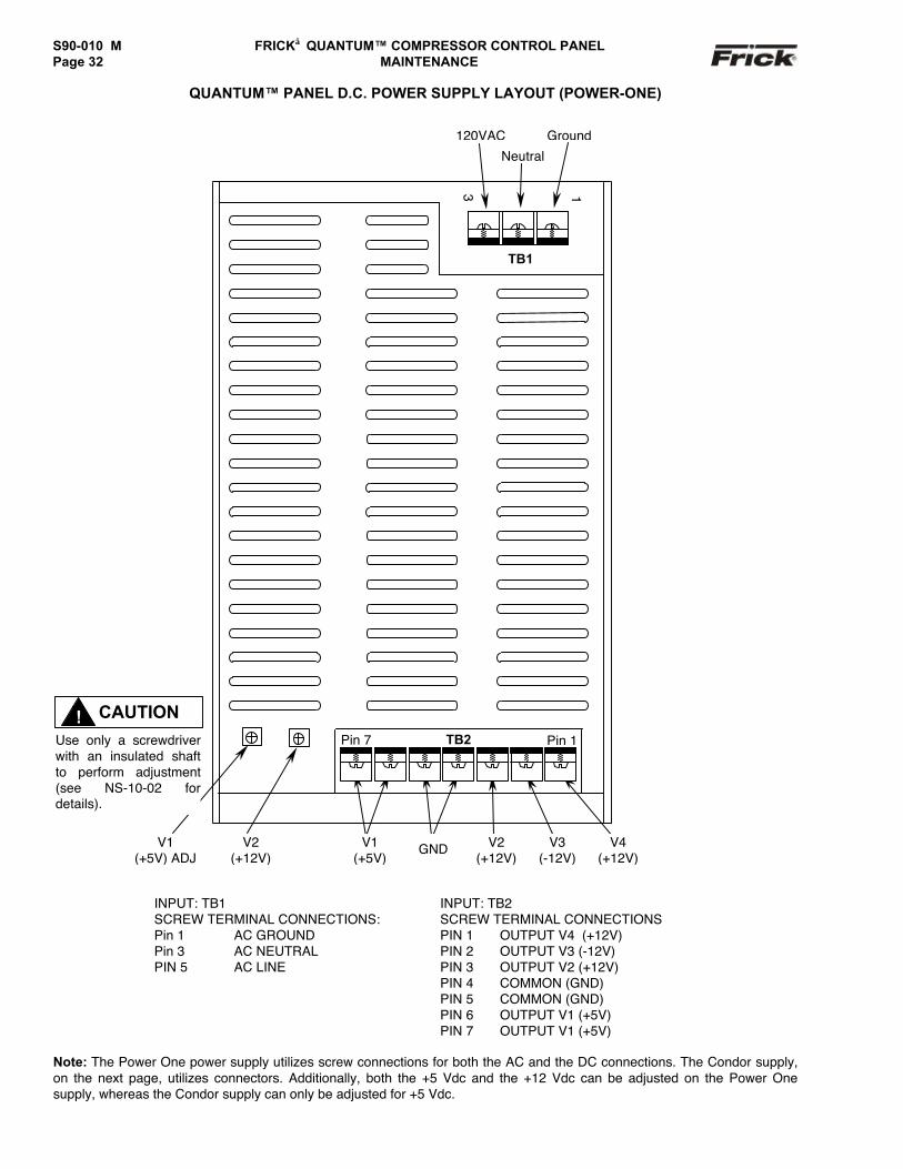
S90-010 M FRICK QUANTUM™ COMPRESSOR CONTROL PANELPage 32 MAINTENANCE
QUANTUM™ PANEL D.C. POWER SUPPLY LAYOUT (POWER-ONE)
INPUT: TB1 INPUT: TB2SCREW TERMINAL CONNECTIONS: SCREW TERMINAL CONNECTIONSPin 1 AC GROUND PIN 1 OUTPUT V4 (+12V)Pin 3 AC NEUTRAL PIN 2 OUTPUT V3 (-12V)PIN 5 AC LINE PIN 3 OUTPUT V2 (+12V)
PIN 4 COMMON (GND)PIN 5 COMMON (GND)PIN 6 OUTPUT V1 (+5V)PIN 7 OUTPUT V1 (+5V)
Note: The Power One power supply utilizes screw connections for both the AC and the DC connections. The Condor supply,on the next page, utilizes connectors. Additionally, both the +5 Vdc and the +12 Vdc can be adjusted on the Power Onesupply, whereas the Condor supply can only be adjusted for +5 Vdc.
120VAC
Neutral
Ground
V2(+12V)
V1(+5V) ADJ
V4(+12V)
V3(-12V)
V2(+12V)
GNDV1(+5V)
TB1
3
Pin 1TB2Pin 7
1
CAUTION!Use only a screwdriverwith an insulated shaftto perform adjustment(see NS-10-02 fordetails).
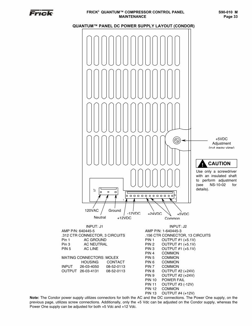
FRICK QUANTUM™ COMPRESSOR CONTROL PANEL S90-010 M MAINTENANCE Page 33
QUANTUM™ PANEL DC POWER SUPPLY LAYOUT (CONDOR)
INPUT: J1 INPUT: J2AMP P/N: 640445-5.312 CTR CONNECTOR, 3 CIRCUITS
AMP P/N: 1-640445-3.156 CTR CONNECTOR, 13 CIRCUITS
Pin 1 AC GROUND PIN 1 OUTPUT #1 (+5.1V)Pin 3 AC NEUTRAL PIN 2 OUTPUT #1 (+5.1V)PIN 5 AC LINE PIN 3 OUTPUT #1 (+5.1V)
PIN 4 COMMONPIN 5 COMMONPIN 6 COMMONPIN 7 COMMONPIN 8 OUTPUT #2 (+24V)PIN 9 OUTPUT #2 (+24V)PIN 10 POWER FAILPIN 11 OUTPUT #3 (-12V)PIN 12 COMMON
MATING CONNECTORS: MOLEX HOUSING CONTACTINPUT 26-03-4050 08-52-0113OUTPUT 26-03-4131 08-52-0113
PIN 13 OUTPUT #4 (+12V)Note: The Condor power supply utilizes connectors for both the AC and the DC connections. The Power One supply, on theprevious page, utilizes screw connections. Additionally, only the +5 Vdc can be adjusted on the Condor supply, whereas thePower One supply can be adjusted for both +5 Vdc and +12 Vdc.
+5VDCAdjustment
(cut away view)
120VAC
Neutral
Ground+5VDC
Common+24VDC-12VDC
+12VDC
J1
J2
11
CAUTION!Use only a screwdriverwith an insulated shaftto perform adjustment(see NS-10-02 fordetails).
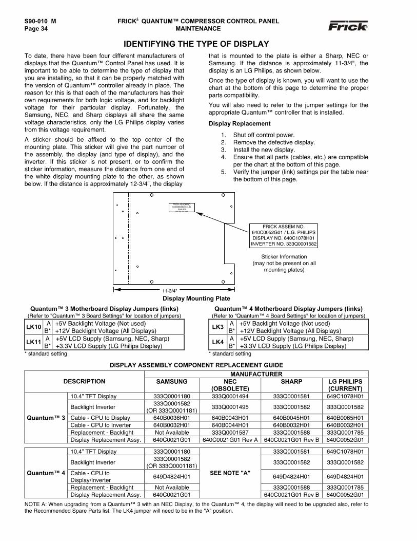
S90-010 M FRICK QUANTUM™ COMPRESSOR CONTROL PANELPage 34 MAINTENANCE
IDENTIFYING THE TYPE OF DISPLAYTo date, there have been four different manufacturers ofdisplays that the Quantum™ Control Panel has used. It isimportant to be able to determine the type of display thatyou are installing, so that it can be properly matched withthe version of Quantum™ controller already in place. Thereason for this is that each of the manufacturers has theirown requirements for both logic voltage, and for backlightvoltage for their particular display. Fortunately, theSamsung, NEC, and Sharp displays all share the samevoltage characteristics, only the LG Philips display variesfrom this voltage requirement.
A sticker should be affixed to the top center of themounting plate. This sticker will give the part number ofthe assembly, the display (and type of display), and theinverter. If this sticker is not present, or to confirm thesticker information, measure the distance from one end ofthe white display mounting plate to the other, as shownbelow. If the distance is approximately 12-3/4", the display
that is mounted to the plate is either a Sharp, NEC orSamsung. If the distance is approximately 11-3/4", thedisplay is an LG Philips, as shown below.
Once the type of display is known, you will want to use thechart at the bottom of this page to determine the properparts compatibility.
You will also need to refer to the jumper settings for theappropriate Quantum™ controller that is installed.
Display Replacement
1. Shut off control power.2. Remove the defective display.3. Install the new display.4. Ensure that all parts (cables, etc.) are compatible
per the chart at the bottom of this page.5. Verify the jumper (link) settings per the table near
the bottom of this page.
Display Mounting Plate
Quantum™ 3 Motherboard Display Jumpers (links)(Refer to "Quantum™ 3 Board Settings" for location of jumpers)
LK10 AB*
+5V Backlight Voltage (Not used)+12V Backlight Voltage (All Displays)
LK11 AB*
+5V LCD Supply (Samsung, NEC, Sharp)+3.3V LCD Supply (LG Philips Display)
* standard setting
Quantum™ 4 Motherboard Display Jumpers (links)(Refer to “Quantum™ 4 Board Settings" for location of jumpers)
LK3 AB*
+5V Backlight Voltage (Not used)+12V Backlight Voltage (All Displays)
LK4 AB*
+5V LCD Supply (Samsung, NEC, Sharp)+3.3V LCD Supply (LG Philips Display)
* standard setting
DISPLAY ASSEMBLY COMPONENT REPLACEMENT GUIDEMANUFACTURER
DESCRIPTION SAMSUNG NEC(OBSOLETE)
SHARP LG PHILIPS(CURRENT)
10.4” TFT Display 333Q0001180 333Q0001494 333Q0001581 649C1078H01
Backlight Inverter 333Q0001582(OR 333Q0001181) 333Q0001495 333Q0001582 333Q0001582
Cable - CPU to Display 640B0036H01 640B0043H01 640B0045H01 640B0065H01Cable - CPU to Inverter 640B0032H01 640B0044H01 640B0032H01 640B0032H01Replacement - Backlight Not Available 333Q0001587 333Q0001588 333Q0001785
Quantum™ 3
Display Replacement Assy. 640C0021G01 640C0021G01 Rev A 640C0021G01 Rev B 640C0052G01
10.4” TFT Display 333Q0001180 333Q0001581 649C1078H01
Backlight Inverter 333Q0001582(OR 333Q0001181) 333Q0001582 333Q0001582
Cable - CPU toDisplay/Inverter 649D4824H01 649D4824H01 649D4824H01
Replacement - Backlight Not Available 333Q0001588 333Q0001785
Quantum™ 4
Display Replacement Assy. 640C0021G01
SEE NOTE "A"
640C0021G01 Rev B 640C0052G01
NOTE A: When upgrading from a Quantum™ 3 with an NEC Display, to the Quantum™ 4, the display will need to be upgraded also, refer tothe Recommended Spare Parts list. The LK4 jumper will need to be in the "A" position.
11-3/4"
FRICK ASSEM NO.640C0052G01 / L.G.
PHILIPSDISPLAY NO.
FRICK ASSEM NO.640C0052G01 / L.G. PHILIPSDISPLAY NO. 640C1078H01
INVERTER NO. 333Q0001582
Sticker Information(may not be present on all
mounting plates)
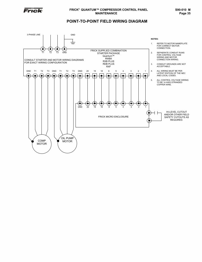
FRICK QUANTUM™ COMPRESSOR CONTROL PANEL S90-010 M MAINTENANCE Page 35
POINT-TO-POINT FIELD WIRING DIAGRAM
GND T1 T2 T3 GND T1 T2 T3 GND 20 19 18 8 5 4 3 2 1
OIL PUMPMOTORCOMP
MOTOR
T1 T2 T3 GND
CONSULT STARTER AND MOTOR WIRING DIAGRAMSFOR EXACT WIRING CONFIGURATION
FRICK SUPPLIED COMBINATIONSTARTER PACKAGE
Quantum™RWBII
RXB PLUSRDB PLUS
RXF
GND
FRICK MICRO ENCLOSURE
20 19 18 8 5 4 3 2 1
NOTES:
1. REFER TO MOTOR NAMEPLATEFOR CORRECT MOTORCONNECTION.
2. SEPAERATE CONDUIT RUNSFOR CONTROL VOLTAGEWIRING AND MOTORCONNECTION WIRING.
3. CONDUIT GROUNDS ARE NOTACCEPTABLE.
4. ALL WIRING MUST BE PERLATEST EDITION OF THE NECAND LOCAL CODES.
5. ALL CONTROL VOLTAGE WIRINGTO BE 14 AWG STRANDEDCOPPER WIRE.
HI-LEVEL CUTOUTAND/OR OTHER FIELDSAFETY CUTOUTS AS
REQUIRED.
3 PHASE LINE GND
S90-010 M FRICK QUANTUM™ COMPRESSOR CONTROL PANELPage 36 MAINTENANCE
TROUBLESHOOTING A PROBLEM THAT APPEARS UNEXPLAINABLEWhen there is a problem that makes no sense due tounexplainable things happening, then check the following:
1. It is important to know if the unit ever workedproperly.
2. If the unit used to work properly, try to determinewhen the problem first showed up.
3. It is important to know if the problem occursrandomly, frequently, or all the time.
4. Check what the temperature is in the engineroom and at the panel. Is it very hot or very cold?• Make sure that the motor is not blowing
exhaust air on the control panel.5. If it just started to act up, then check if there was
recently a severe lightning storm, fire, flood, or aplant accident. If any of the following conditionsare possible, then check for it:• Has any water, refrigerant, or oil leaked into
the panel or conduit?• Does the conduit with the Slide Valve or
Slide Stop contain liquid?• Does the Slide Stop potentiometer cover
contain any liquid?6. If it just started to act up, then check if anything
was recently changed in the system (i.e. softwareor hardware.)
7. If it just started to act up, then check if anyservice was recently done to the compressor orit’s electrical system?
8. If there is communication wiring connecting thepanel to another panel or device, then check thefollowing:• If the Quantum™ is unexplainably shutting
down, try disconnecting the communicationscable to see if the problem goes away.
• Check if the communications cable shieldsare tied to machine ground at only onelocation. For a PLC or Opto22 basedsystem, the shield should normally be tiedonly at the PLC or Opto22 panel. For dualsequencing machines, the shield should onlybe tied to ground in one panel, typically the“Lead” machine.
• Check that you are using the Frick
recommended communications cable. Seemanual to match proper cable with type ofcommunications (i.e., RS-422, RS-232, RS-485, or some other type of factorycommunication bus system.)
9. If this is an older plant, has the plant wiring beenbrought up to code?
10. Do you have power wiring mixed with controlwiring?
11. Do you have power wiring mixed with sensorwiring?
12. Do you have power wiring mixed withcommunications wiring?
13. Check that the starter panel is grounded to theplant transformer. There are usually four wires: 3for the 3 phases and 1 for plant ground.
14. Check that the motor is grounded to the starterpanel. There are usually four wires: 3 for thephases and 1 for ground.
15. Ensure that one side of the motor currenttransformer is grounded in the motor starterpanel. The wire to the control panel terminal #2 isusually the only one grounded.
16. Check that the pressure transducers are properlygrounded. The two types of transducers you mayhave are as follows: an older type has an 8 to 10inch 3-conductor pigtail coming out of thetransducer. This type will have the attachingcable’s shield cut off and insulated at thetransducer end. The shield is then tied to a panelground terminal in the panel. The newer type hasthe cable as an integral part of the housing andhas the shield crimped to the case at thetransducer end. This type of transducer has thecable’s shield cut off and insulated in the controlpanel.
17. Check that the temperature transducers areproperly grounded. The temperature probesusually have two short wires coming out of thesensor, and are tied to a shielded cable at thethermal well head. The shield is insulated at thetemperature probe and grounded at the panelend.
18. Check if one of the temperature probes has asignal wire shorted to machine ground. To dothis, first pull the orange plug from the microboard and then use a DVM and check each whitewire to machine ground and each black wire tomachine ground.
19. Check that all inductive loads (i.e. Coils,Solenoids, or Relays, etc.) connected to the I/Ooutput modules have surge suppressers acrossthem, preferably at the devices and not at thepanel end.
20. If the compressor control settings unexplainablychange modes, it may be a noise problemaffecting the keypad’s input circuit. Check if itworks OK with the keypad cable disconnected. Ifit works OK, then check the grounding asdescribed above. If the grounding is OK thenreplace the keypad.
21. Make sure that you have a continuous groundback to the power source. The ground connectionmust be aluminum or copper. A conduit groundwill not work. Do not drive a ground stake at thecompressor since extraneous currents will beattracted to the compressor.
22. Make sure that there is no AC wiring lying next tothe printed circuit board.
23. Unexplainable compressor auxiliary failures areusually indicative of noise due to wiring problems(i.e. incorrect earth grounds, mixed power andcontrol wiring, unsuppressed coils, etc)
24. If the compressor is unexplainably shutting down,check if the machine shares control transformerpower with something else. Make sure eachcompressor has its own isolation transformer inthe motor control center off the three-phase buswith the secondary properly grounded.
FRICK QUANTUM™ COMPRESSOR CONTROL PANEL S90-010 MMAINTENANCE Page 37
TROUBLESHOOTING CHART FOR FRICK QUANTUM™ CONTROL PANEL(REFER TO WIRING DIAGRAMS)
SYMPTOM PROBABLE CAUSES and CORRECTIONSDISPLAY IS INOPERATIVE Check for power at the panel. See if any of the diagnostic lamps on the Main
Board are blinking or any lights are blinking on the other boards. If no lightsare blinking, make sure the control power switch is switched on. If there arestill no lights, then check the circuit breaker (2CB). If the breaker is not tripped,check for power into 2CB. If there is no power, check the external power beingsupplied. If power from 2CB, check power supply for input AC and output DClevel.
Shut off power to the panel and first confirm that the display connector is firmlyseated . This is a delicate connection and care should be used to reconnect it.Confirm that the connectors at both ends of the backlight inverter are properlyconnected. Confirm that the display harness (and inverter harness for theQuantum™ 3) are connected properly on the main board.
Reference Dwg. No. 640D0070 sheet 2.OIL PUMP DOES NOT START The LED (D3) for Output 3 (MOD 3) of Digital I/O Board #1 should be on when
Manually On is selected for the oil pump mode. If the pump does not startwhen the LED is on, check for the proper panel voltage between position 4and 5 on the P1 DIO connector on Digital I/O board #1. If the proper voltage isnot found, check the fuse (F3) and if the fuse is OK, check the output module(MOD 3). If the voltage was OK, check for the proper voltage between position5 on the P1 DIO connector and position 8 on the terminal strip. If voltage isOK, check for the proper voltage between position 8 and 2 on the terminalstrip. If the voltage is OK, check at the oil pump starter.
The Oil Pump #1 Auxiliary Contact switches voltage to Input 4 (MOD 4) ofDigital I/O Board #1 when the auxiliary contacts are closed. If the input doesnot turn on, check if the LED (D4) is lit when it should be. If it isn’t, check thefuse (F4) and if the fuse is OK, check the input module (MOD 4). Check thevoltage between positions 4 and 6 of the P1 DIO connector.
OIL PUMP IS RUNNING BUT THECOMPRESSOR DOES NOT START
If shutdown message “Compressor Starting, Low Oil Pressure - Shutdown” isdisplayed, refer to the section in the compressor manual on troubleshootingthe oil pump system. For compressor models with a slide valve: Verify that theSlide Valve has unloaded to or below the “Highest Slide Valve Position toallow starting the compressor” setpoint. If the slide valve has not unloaded,troubleshoot the hydraulic system. Compressor will not start until the SlideValve is unloaded. Output 1 (MOD 1) of Digital I/O Board #1 controls the motorstarter. If the motor does not start when the LED (D1) is on, check for theproper panel voltage between position 4 and 1 on the P1 DIO connector onDigital I/O board #1. If the proper voltage is not found, check the fuse (F1) andif the fuse is OK, check the output module (MOD 1). If the voltage was OK,check for the proper voltage between position 1 on the P1 DIO connector andposition 18 on the terminal strip. If voltage is OK, check for the proper voltagebetween position 18 and 2 on the terminal strip. If the voltage is OK, check theinterposing relay (By others).
COMPRESSOR AUXILIARYSHUTDOWN
Output 1 controls the Compressor Start Relay (By others). If the compressordoes not start and the LED (D1) for Output 1 (MOD 1) is on, check for theproper panel voltage between position 4 and 1 on the P1 DIO connector onDigital I/O board #1. If the proper voltage is not found, check the fuse (F1) andif the fuse is OK, check the output module (MOD 1). If the voltage was OK,check for the proper voltage between position 1 on the P1 DIO connector andposition 18 on the terminal strip. If voltage is OK, check for the proper voltagebetween position 18 and 2 on the terminal strip. If the voltage is OK, check theinterposing relay (By others).
The Compressor Starter Auxiliary Contacts turn on Input 2 (MOD 2) of DigitalI/O Board #1 when they are closed. These contacts are located on theCompressor Starter. If the input does not turn on check if the LED (D2) is litwhen it should be. If it isn’t, check the fuse (F2) and if the fuse is OK, checkthe input module (MOD 2). Check the voltage between positions 2 and 4 of theP1 DIO connector.
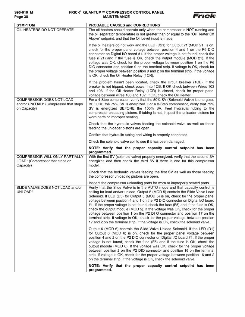
S90-010 M FRICK QUANTUM™ COMPRESSOR CONTROL PANELPage 38 MAINTENANCE
SYMPTOM PROBABLE CAUSES and CORRECTIONSOIL HEATERS DO NOT OPERATE The oil heaters should operate only when the compressor is NOT running and
the oil separator temperature is not greater than or equal to the “Oil Heater OffAbove” setpoint, and that the Oil Level input is made.
If the oil heaters do not work and the LED (D21) for Output 21 (MOD 21) is on,check for the proper panel voltage between position 4 and 1 on the P6 DIOconnector on Digital I/O board #1. If the proper voltage is not found, check thefuse (F21) and if the fuse is OK, check the output module (MOD 21). If thevoltage was OK, check for the proper voltage between position 1 on the P6DIO connector and position 9 on the terminal strip. If voltage is OK, check forthe proper voltage between position 9 and 2 on the terminal strip. If the voltageis OK, check the Oil Heater Relay (1CR).
If the problem hasn’t been located, check the circuit breaker (1CB). If thebreaker is not tripped, check power into 1CB. If OK check between Wires 103and 106. If the Oil Heater Relay (1CR) is closed, check for proper panelvoltage between wires 106 and 102. If OK, check the Oil Heater.
COMPRESSOR DOES NOT LOADand/or UNLOAD* (Compressor that stepson Capacity)
For a 4-Step compressor, verify that the 50% SV (Solenoid Valve) is energizedBEFORE the 75% SV is energized. For a 3-Step compressor, verify that 75%SV is energized BEFORE the 100% SV. Feel hydraulic tubing to thecompressor unloading pistons. If tubing is hot, inspect the unloader pistons forworn parts or improper seating.
Check that the hydraulic valves feeding the solenoid valve as well as thosefeeding the unloader pistons are open.
Confirm that hydraulic tubing and wiring is properly connected.
Check the solenoid valve coil to see if it has been damaged.
NOTE: Verify that the proper capacity control setpoint has beenprogrammed.
COMPRESSOR WILL ONLY PARTIALLYLOAD* (Compressor that steps onCapacity)
With the first SV (solenoid valve) properly energized, verify that the second SVenergizes and then check the third SV if there is one for this compressormodel.
Check that the hydraulic valves feeding the first SV as well as those feedingthe compressor unloading pistons are open.
Inspect the compressor unloading ports for worn or improperly seated parts.SLIDE VALVE DOES NOT LOAD and/orUNLOAD*
Verify that the Slide Valve is in the AUTO mode and that capacity control iscalling for load and/or unload. Output 5 (MOD 5) controls the Slide Valve LoadSolenoid. If LED (D5) for Output 5 (MOD 5) is on, check for the proper panelvoltage between position 4 and 1 on the P2 DIO connector on Digital I/O board#1. If the proper voltage is not found, check the fuse (F5) and if the fuse is OK,check the output module (MOD 5). If the voltage was OK, check for the propervoltage between position 1 on the P2 DI O connector and position 17 on theterminal strip. If voltage is OK, check for the proper voltage between position17 and 2 on the terminal strip. If the voltage is OK, check the solenoid valve.
Output 6 (MOD 6) controls the Slide Valve Unload Solenoid. If the LED (D1)for Output 6 (MOD 6) is on, check for the proper panel voltage betweenposition 4 and 2 on the P2 DIO connector on Digital I/O board #1. If the propervoltage is not found, check the fuse (F6) and if the fuse is OK, check theoutput module (MOD 6). If the voltage was OK, check for the proper voltagebetween position 2 on the P2 DIO connector and position 16 on the terminalstrip. If voltage is OK, check for the proper voltage between position 16 and 2on the terminal strip. If the voltage is OK, check the solenoid valve.
NOTE: Verify that the proper capacity control setpoint has beenprogrammed.
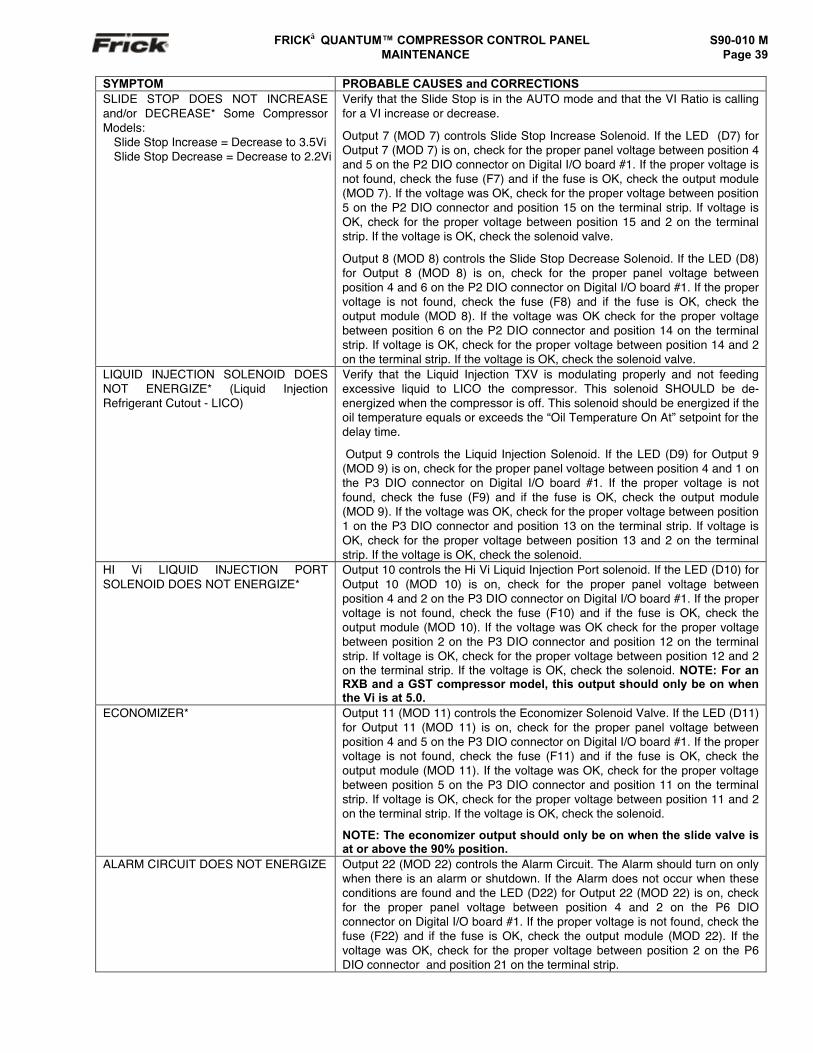
FRICK QUANTUM™ COMPRESSOR CONTROL PANEL S90-010 MMAINTENANCE Page 39
SYMPTOM PROBABLE CAUSES and CORRECTIONSSLIDE STOP DOES NOT INCREASEand/or DECREASE* Some CompressorModels:
Slide Stop Increase = Decrease to 3.5ViSlide Stop Decrease = Decrease to 2.2Vi
Verify that the Slide Stop is in the AUTO mode and that the VI Ratio is callingfor a VI increase or decrease.
Output 7 (MOD 7) controls Slide Stop Increase Solenoid. If the LED (D7) forOutput 7 (MOD 7) is on, check for the proper panel voltage between position 4and 5 on the P2 DIO connector on Digital I/O board #1. If the proper voltage isnot found, check the fuse (F7) and if the fuse is OK, check the output module(MOD 7). If the voltage was OK, check for the proper voltage between position5 on the P2 DIO connector and position 15 on the terminal strip. If voltage isOK, check for the proper voltage between position 15 and 2 on the terminalstrip. If the voltage is OK, check the solenoid valve.
Output 8 (MOD 8) controls the Slide Stop Decrease Solenoid. If the LED (D8)for Output 8 (MOD 8) is on, check for the proper panel voltage betweenposition 4 and 6 on the P2 DIO connector on Digital I/O board #1. If the propervoltage is not found, check the fuse (F8) and if the fuse is OK, check theoutput module (MOD 8). If the voltage was OK check for the proper voltagebetween position 6 on the P2 DIO connector and position 14 on the terminalstrip. If voltage is OK, check for the proper voltage between position 14 and 2on the terminal strip. If the voltage is OK, check the solenoid valve.
LIQUID INJECTION SOLENOID DOESNOT ENERGIZE* (Liquid InjectionRefrigerant Cutout - LICO)
Verify that the Liquid Injection TXV is modulating properly and not feedingexcessive liquid to LICO the compressor. This solenoid SHOULD be de-energized when the compressor is off. This solenoid should be energized if theoil temperature equals or exceeds the “Oil Temperature On At” setpoint for thedelay time.
Output 9 controls the Liquid Injection Solenoid. If the LED (D9) for Output 9(MOD 9) is on, check for the proper panel voltage between position 4 and 1 onthe P3 DIO connector on Digital I/O board #1. If the proper voltage is notfound, check the fuse (F9) and if the fuse is OK, check the output module(MOD 9). If the voltage was OK, check for the proper voltage between position1 on the P3 DIO connector and position 13 on the terminal strip. If voltage isOK, check for the proper voltage between position 13 and 2 on the terminalstrip. If the voltage is OK, check the solenoid.
HI Vi LIQUID INJECTION PORTSOLENOID DOES NOT ENERGIZE*
Output 10 controls the Hi Vi Liquid Injection Port solenoid. If the LED (D10) forOutput 10 (MOD 10) is on, check for the proper panel voltage betweenposition 4 and 2 on the P3 DIO connector on Digital I/O board #1. If the propervoltage is not found, check the fuse (F10) and if the fuse is OK, check theoutput module (MOD 10). If the voltage was OK check for the proper voltagebetween position 2 on the P3 DIO connector and position 12 on the terminalstrip. If voltage is OK, check for the proper voltage between position 12 and 2on the terminal strip. If the voltage is OK, check the solenoid. NOTE: For anRXB and a GST compressor model, this output should only be on whenthe Vi is at 5.0.
ECONOMIZER* Output 11 (MOD 11) controls the Economizer Solenoid Valve. If the LED (D11)for Output 11 (MOD 11) is on, check for the proper panel voltage betweenposition 4 and 5 on the P3 DIO connector on Digital I/O board #1. If the propervoltage is not found, check the fuse (F11) and if the fuse is OK, check theoutput module (MOD 11). If the voltage was OK, check for the proper voltagebetween position 5 on the P3 DIO connector and position 11 on the terminalstrip. If voltage is OK, check for the proper voltage between position 11 and 2on the terminal strip. If the voltage is OK, check the solenoid.
NOTE: The economizer output should only be on when the slide valve isat or above the 90% position.
ALARM CIRCUIT DOES NOT ENERGIZE Output 22 (MOD 22) controls the Alarm Circuit. The Alarm should turn on onlywhen there is an alarm or shutdown. If the Alarm does not occur when theseconditions are found and the LED (D22) for Output 22 (MOD 22) is on, checkfor the proper panel voltage between position 4 and 2 on the P6 DIOconnector on Digital I/O board #1. If the proper voltage is not found, check thefuse (F22) and if the fuse is OK, check the output module (MOD 22). If thevoltage was OK, check for the proper voltage between position 2 on the P6DIO connector and position 21 on the terminal strip.
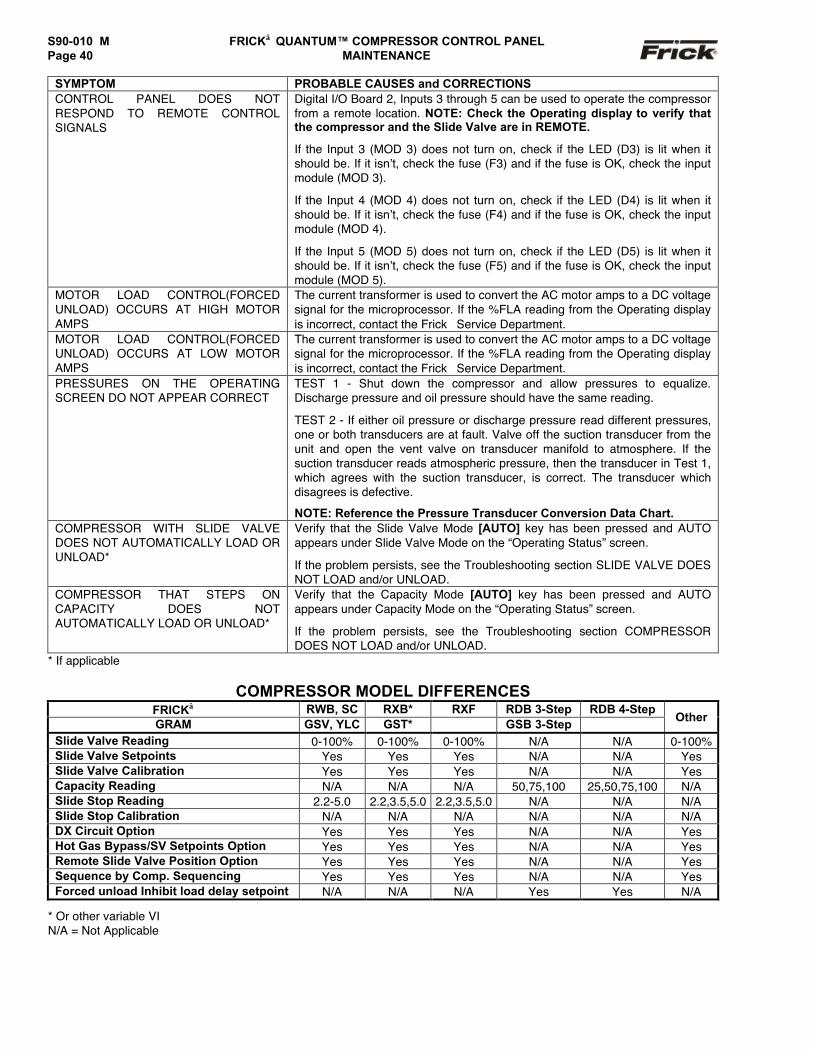
S90-010 M FRICK QUANTUM™ COMPRESSOR CONTROL PANELPage 40 MAINTENANCE
SYMPTOM PROBABLE CAUSES and CORRECTIONSCONTROL PANEL DOES NOTRESPOND TO REMOTE CONTROLSIGNALS
Digital I/O Board 2, Inputs 3 through 5 can be used to operate the compressorfrom a remote location. NOTE: Check the Operating display to verify thatthe compressor and the Slide Valve are in REMOTE.
If the Input 3 (MOD 3) does not turn on, check if the LED (D3) is lit when itshould be. If it isn’t, check the fuse (F3) and if the fuse is OK, check the inputmodule (MOD 3).
If the Input 4 (MOD 4) does not turn on, check if the LED (D4) is lit when itshould be. If it isn’t, check the fuse (F4) and if the fuse is OK, check the inputmodule (MOD 4).
If the Input 5 (MOD 5) does not turn on, check if the LED (D5) is lit when itshould be. If it isn’t, check the fuse (F5) and if the fuse is OK, check the inputmodule (MOD 5).
MOTOR LOAD CONTROL(FORCEDUNLOAD) OCCURS AT HIGH MOTORAMPS
The current transformer is used to convert the AC motor amps to a DC voltagesignal for the microprocessor. If the %FLA reading from the Operating displayis incorrect, contact the Frick Service Department.
MOTOR LOAD CONTROL(FORCEDUNLOAD) OCCURS AT LOW MOTORAMPS
The current transformer is used to convert the AC motor amps to a DC voltagesignal for the microprocessor. If the %FLA reading from the Operating displayis incorrect, contact the Frick Service Department.
PRESSURES ON THE OPERATINGSCREEN DO NOT APPEAR CORRECT
TEST 1 - Shut down the compressor and allow pressures to equalize.Discharge pressure and oil pressure should have the same reading.
TEST 2 - If either oil pressure or discharge pressure read different pressures,one or both transducers are at fault. Valve off the suction transducer from theunit and open the vent valve on transducer manifold to atmosphere. If thesuction transducer reads atmospheric pressure, then the transducer in Test 1,which agrees with the suction transducer, is correct. The transducer whichdisagrees is defective.
NOTE: Reference the Pressure Transducer Conversion Data Chart.COMPRESSOR WITH SLIDE VALVEDOES NOT AUTOMATICALLY LOAD ORUNLOAD*
Verify that the Slide Valve Mode [AUTO] key has been pressed and AUTOappears under Slide Valve Mode on the “Operating Status” screen.
If the problem persists, see the Troubleshooting section SLIDE VALVE DOESNOT LOAD and/or UNLOAD.
COMPRESSOR THAT STEPS ONCAPACITY DOES NOTAUTOMATICALLY LOAD OR UNLOAD*
Verify that the Capacity Mode [AUTO] key has been pressed and AUTOappears under Capacity Mode on the “Operating Status” screen.
If the problem persists, see the Troubleshooting section COMPRESSORDOES NOT LOAD and/or UNLOAD.
* If applicable
COMPRESSOR MODEL DIFFERENCESFRICK RWB, SC RXB* RXF RDB 3-Step RDB 4-StepGRAM GSV, YLC GST* GSB 3-Step Other
Slide Valve Reading 0-100% 0-100% 0-100% N/A N/A 0-100%Slide Valve Setpoints Yes Yes Yes N/A N/A YesSlide Valve Calibration Yes Yes Yes N/A N/A YesCapacity Reading N/A N/A N/A 50,75,100 25,50,75,100 N/ASlide Stop Reading 2.2-5.0 2.2,3.5,5.0 2.2,3.5,5.0 N/A N/A N/ASlide Stop Calibration N/A N/A N/A N/A N/A N/ADX Circuit Option Yes Yes Yes N/A N/A YesHot Gas Bypass/SV Setpoints Option Yes Yes Yes N/A N/A YesRemote Slide Valve Position Option Yes Yes Yes N/A N/A YesSequence by Comp. Sequencing Yes Yes Yes N/A N/A YesForced unload Inhibit load delay setpoint N/A N/A N/A Yes Yes N/A
* Or other variable VIN/A = Not Applicable
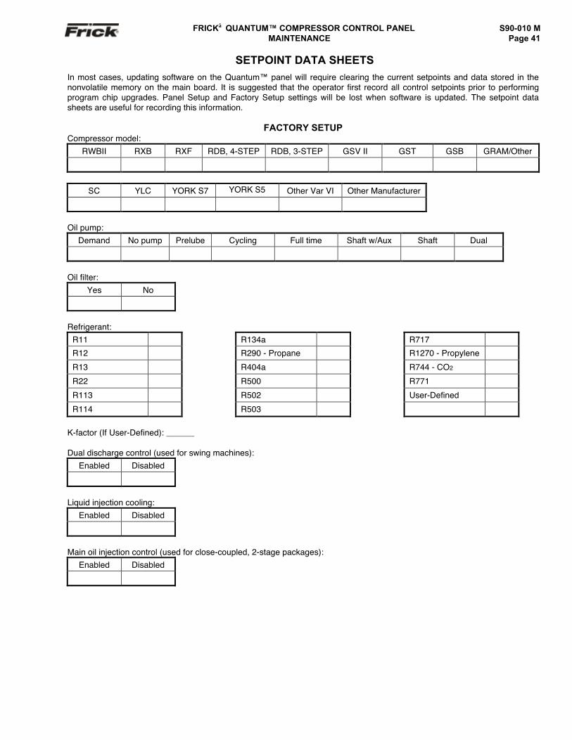
FRICK QUANTUM™ COMPRESSOR CONTROL PANEL S90-010 MMAINTENANCE Page 41
SETPOINT DATA SHEETSIn most cases, updating software on the Quantum™ panel will require clearing the current setpoints and data stored in thenonvolatile memory on the main board. It is suggested that the operator first record all control setpoints prior to performingprogram chip upgrades. Panel Setup and Factory Setup settings will be lost when software is updated. The setpoint datasheets are useful for recording this information.
FACTORY SETUPCompressor model:
RWBII RXB RXF RDB, 4-STEP RDB, 3-STEP GSV II GST GSB GRAM/Other
SC YLC YORK S7 YORK S5 Other Var VI Other Manufacturer
Oil pump:Demand No pump Prelube Cycling Full time Shaft w/Aux Shaft Dual
Oil filter:Yes No
Refrigerant:R11 R134a R717
R12 R290 - Propane R1270 - Propylene
R13 R404a R744 - CO2
R22 R500 R771
R113 R502 User-Defined
R114 R503
K-factor (If User-Defined): ______
Dual discharge control (used for swing machines):Enabled Disabled
Liquid injection cooling:Enabled Disabled
Main oil injection control (used for close-coupled, 2-stage packages):Enabled Disabled
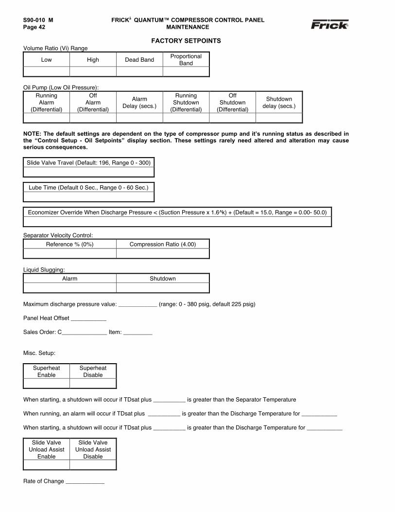
S90-010 M FRICK QUANTUM™ COMPRESSOR CONTROL PANELPage 42 MAINTENANCE
FACTORY SETPOINTSVolume Ratio (Vi) Range
Low High Dead Band ProportionalBand
Oil Pump (Low Oil Pressure):Running
Alarm(Differential)
OffAlarm
(Differential)
AlarmDelay (secs.)
RunningShutdown
(Differential)
OffShutdown
(Differential)
Shutdowndelay (secs.)
NOTE: The default settings are dependent on the type of compressor pump and it’s running status as described inthe “Control Setup - Oil Setpoints” display section. These settings rarely need altered and alteration may causeserious consequences.
Slide Valve Travel (Default: 196, Range 0 - 300)
Lube Time (Default 0 Sec., Range 0 - 60 Sec.)
Economizer Override When Discharge Pressure < (Suction Pressure x 1.6^k) + (Default = 15.0, Range = 0.00- 50.0)
Separator Velocity Control:Reference % (0%) Compression Ratio (4.00)
Liquid Slugging:Alarm Shutdown
Maximum discharge pressure value: ____________ (range: 0 - 380 psig, default 225 psig)
Panel Heat Offset ___________
Sales Order: C______________ Item: _________
Misc. Setup:
SuperheatEnable
SuperheatDisable
When starting, a shutdown will occur if TDsat plus __________ is greater than the Separator Temperature
When running, an alarm will occur if TDsat plus __________ is greater than the Discharge Temperature for ___________
When starting, a shutdown will occur if TDsat plus __________ is greater than the Discharge Temperature for ___________
Slide ValveUnload Assist
Enable
Slide ValveUnload Assist
Disable
Rate of Change ____________
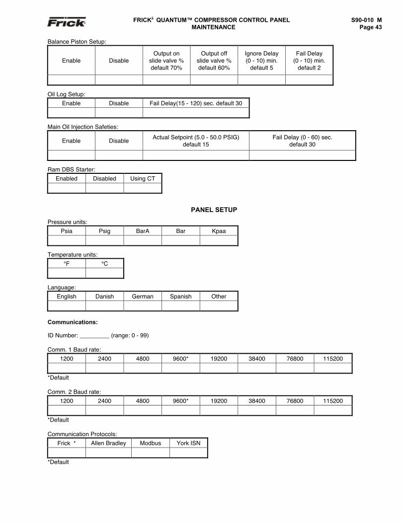
FRICK QUANTUM™ COMPRESSOR CONTROL PANEL S90-010 M MAINTENANCE Page 43
Balance Piston Setup:
Enable DisableOutput on
slide valve %default 70%
Output offslide valve %default 60%
Ignore Delay(0 - 10) min.
default 5
Fail Delay(0 - 10) min.
default 2
Oil Log Setup:Enable Disable Fail Delay(15 - 120) sec. default 30
Main Oil Injection Safeties:
Enable Disable Actual Setpoint (5.0 - 50.0 PSIG)default 15
Fail Delay (0 - 60) sec.default 30
Ram DBS Starter:Enabled Disabled Using CT
PANEL SETUP
Pressure units:Psia Psig BarA Bar Kpaa
Temperature units:°F °C
Language:English Danish German Spanish Other
Communications:
ID Number: _________ (range: 0 - 99)
Comm. 1 Baud rate:1200 2400 4800 9600* 19200 38400 76800 115200
*Default
Comm. 2 Baud rate:1200 2400 4800 9600* 19200 38400 76800 115200
*Default
Communication Protocols:Frick* Allen Bradley Modbus York ISN
*Default
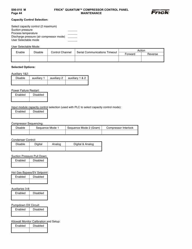
S90-010 M FRICK QUANTUM™ COMPRESSOR CONTROL PANELPage 44 MAINTENANCE
Capacity Control Selection:
Select capacity control (2 maximum)Suction pressure ______Process temperature ______Discharge pressure (air compressor mode) ______User Selectable mode ______
User Selectable Mode:Action
Enable Disable Control Channel Serial Communications TimeoutForward Reverse
Selected Options:
Auxiliary 1&2:Disable auxiliary 1 auxiliary 2 auxiliary 1 & 2
Power Failure Restart:Enabled Disabled
Input module capacity control selection (used with PLC to select capacity control mode):Enabled Disabled
Compressor Sequencing:Disable Sequence Mode 1 Sequence Mode 2 (Gram) Compressor Interlock
Condenser Control:Disable Digital Analog Digital & Analog
Suction Pressure Pull Down:Enabled Disabled
Hot Gas Bypass/SV Setpoint:Enabled Disabled
Auxiliaries 3-8:Enabled Disabled
Pumpdown DX Circuit:Enabled Disabled
Kilowatt Monitor Calibration and Setup:Enabled Disabled
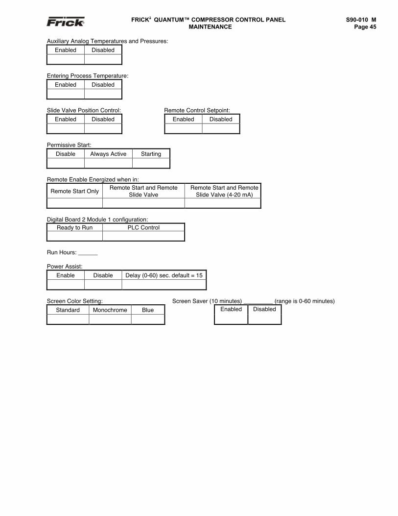
FRICK QUANTUM™ COMPRESSOR CONTROL PANEL S90-010 M MAINTENANCE Page 45
Auxiliary Analog Temperatures and Pressures:Enabled Disabled
Entering Process Temperature:Enabled Disabled
Slide Valve Position Control: Remote Control Setpoint:Enabled Disabled Enabled Disabled
Permissive Start:Disable Always Active Starting
Remote Enable Energized when in:
Remote Start Only Remote Start and RemoteSlide Valve
Remote Start and RemoteSlide Valve (4-20 mA)
Digital Board 2 Module 1 configuration:Ready to Run PLC Control
Run Hours: ______
Power Assist:Enable Disable Delay (0-60) sec. default = 15
Screen Color Setting: Screen Saver (10 minutes) _________ (range is 0-60 minutes)Standard Monochrome Blue Enabled Disabled
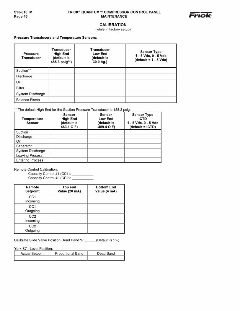
S90-010 M FRICK QUANTUM™ COMPRESSOR CONTROL PANELPage 46 MAINTENANCE
CALIBRATION(while in factory setup)
Pressure Transducers and Temperature Sensors:
PressureTransducer
TransducerHigh End(default is
485.3 psig**)
TransducerLow End
(default is30.0 hg.)
Sensor Type1 - 5 Vdc, 0 - 5 Vdc(default = 1 - 5 Vdc)
Suction**
Discharge
Oil
Filter
System Discharge
Balance Piston
** The default High End for the Suction Pressure Transducer is 185.3 psig.
TemperatureSensor
SensorHigh End(default is463.1 O F)
SensorLow End
(default is-459.4 O F)
Sensor TypeICTD
1 - 5 Vdc, 0 - 5 Vdc(default = ICTD)
SuctionDischargeOilSeparatorSystem DischargeLeaving ProcessEntering Process
Remote Control Calibration:Capacity Control #1 (CC1): ___________Capacity Control #2 (CC2): ___________
RemoteSetpoint
Top endValue (20 mA)
Bottom EndValue (4 mA)
CC1Incoming
CC1Outgoing
CC2Incoming
CC2Outgoing
Calibrate Slide Valve Position Dead Band %: _____ (Default is 1%)
York S7 - Level Position:Actual Setpoint Proportional Band Dead Band
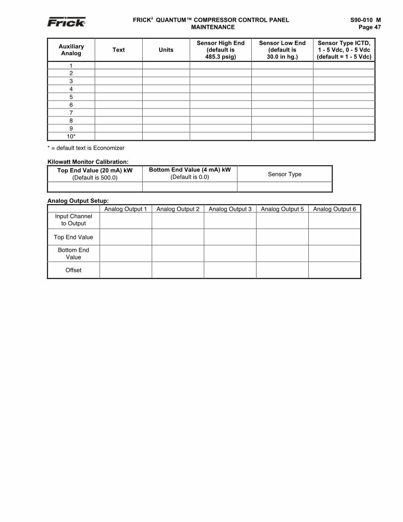
FRICK QUANTUM™ COMPRESSOR CONTROL PANEL S90-010 M MAINTENANCE Page 47
AuxiliaryAnalog Text Units
Sensor High End(default is485.3 psig)
Sensor Low End(default is30.0 in hg.)
Sensor Type ICTD,1 - 5 Vdc, 0 - 5 Vdc(default = 1 - 5 Vdc)
123456789
10*
* = default text is Economizer
Kilowatt Monitor Calibration:Top End Value (20 mA) kW
(Default is 500.0)Bottom End Value (4 mA) kW
(Default is 0.0) Sensor Type
Analog Output Setup:Analog Output 1 Analog Output 2 Analog Output 3 Analog Output 5 Analog Output 6
Input Channelto Output
Top End Value
Bottom EndValue
Offset
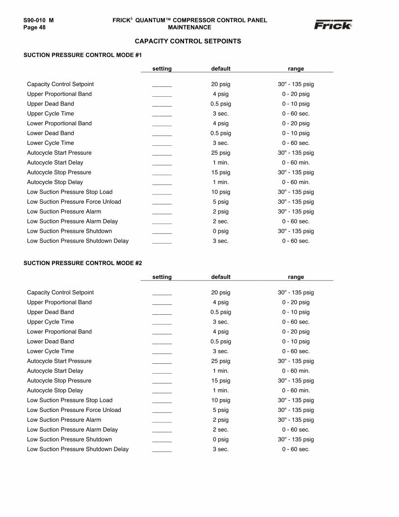
S90-010 M FRICK QUANTUM™ COMPRESSOR CONTROL PANELPage 48 MAINTENANCE
CAPACITY CONTROL SETPOINTS
SUCTION PRESSURE CONTROL MODE #1
setting default range
Capacity Control Setpoint ______ 20 psig 30" - 135 psig
Upper Proportional Band ______ 4 psig 0 - 20 psig
Upper Dead Band ______ 0.5 psig 0 - 10 psig
Upper Cycle Time ______ 3 sec. 0 - 60 sec.
Lower Proportional Band ______ 4 psig 0 - 20 psig
Lower Dead Band ______ 0.5 psig 0 - 10 psig
Lower Cycle Time ______ 3 sec. 0 - 60 sec.
Autocycle Start Pressure ______ 25 psig 30" - 135 psig
Autocycle Start Delay ______ 1 min. 0 - 60 min.
Autocycle Stop Pressure ______ 15 psig 30" - 135 psig
Autocycle Stop Delay ______ 1 min. 0 - 60 min.
Low Suction Pressure Stop Load ______ 10 psig 30" - 135 psig
Low Suction Pressure Force Unload ______ 5 psig 30" - 135 psig
Low Suction Pressure Alarm ______ 2 psig 30" - 135 psig
Low Suction Pressure Alarm Delay ______ 2 sec. 0 - 60 sec.
Low Suction Pressure Shutdown ______ 0 psig 30" - 135 psig
Low Suction Pressure Shutdown Delay ______ 3 sec. 0 - 60 sec.
SUCTION PRESSURE CONTROL MODE #2
setting default range
Capacity Control Setpoint ______ 20 psig 30" - 135 psig
Upper Proportional Band ______ 4 psig 0 - 20 psig
Upper Dead Band ______ 0.5 psig 0 - 10 psig
Upper Cycle Time ______ 3 sec. 0 - 60 sec.
Lower Proportional Band ______ 4 psig 0 - 20 psig
Lower Dead Band ______ 0.5 psig 0 - 10 psig
Lower Cycle Time ______ 3 sec. 0 - 60 sec.
Autocycle Start Pressure ______ 25 psig 30" - 135 psig
Autocycle Start Delay ______ 1 min. 0 - 60 min.
Autocycle Stop Pressure ______ 15 psig 30" - 135 psig
Autocycle Stop Delay ______ 1 min. 0 - 60 min.
Low Suction Pressure Stop Load ______ 10 psig 30" - 135 psig
Low Suction Pressure Force Unload ______ 5 psig 30" - 135 psig
Low Suction Pressure Alarm ______ 2 psig 30" - 135 psig
Low Suction Pressure Alarm Delay ______ 2 sec. 0 - 60 sec.
Low Suction Pressure Shutdown ______ 0 psig 30" - 135 psig
Low Suction Pressure Shutdown Delay ______ 3 sec. 0 - 60 sec.
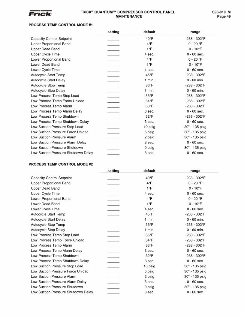
FRICK QUANTUM™ COMPRESSOR CONTROL PANEL S90-010 M MAINTENANCE Page 49
PROCESS TEMP CONTROL MODE #1
setting default range
Capacity Control Setpoint ______ 40°F -238 - 302°FUpper Proportional Band ______ 4°F 0 - 20 °FUpper Dead Band ______ 1°F 0 - 10°FUpper Cycle Time ______ 4 sec. 0 - 60 sec.Lower Proportional Band ______ 4°F 0 - 20 °FLower Dead Band ______ 1°F 0 - 10°FLower Cycle Time ______ 4 sec. 0 - 60 sec.Autocycle Start Temp ______ 45°F -238 - 302°FAutocycle Start Delay ______ 1 min. 0 - 60 min.Autocycle Stop Temp ______ 36°F -238 - 302°FAutocycle Stop Delay ______ 1 min. 0 - 60 min.Low Process Temp Stop Load ______ 35°F -238 - 302°FLow Process Temp Force Unload ______ 34°F -238 - 302°FLow Process Temp Alarm ______ 33°F -238 - 302°FLow Process Temp Alarm Delay ______ 3 sec. 0 - 60 sec.Low Process Temp Shutdown ______ 32°F -238 - 302°FLow Process Temp Shutdown Delay ______ 3 sec. 0 - 60 sec.Low Suction Pressure Stop Load ______ 10 psig 30" - 135 psigLow Suction Pressure Force Unload ______ 5 psig 30" - 135 psigLow Suction Pressure Alarm ______ 2 psig 30" - 135 psigLow Suction Pressure Alarm Delay ______ 3 sec. 0 - 60 sec.Low Suction Pressure Shutdown ______ 0 psig 30" - 135 psigLow Suction Pressure Shutdown Delay ______ 3 sec. 0 - 60 sec.
PROCESS TEMP CONTROL MODE #2
setting default range
Capacity Control Setpoint ______ 40°F -238 - 302°FUpper Proportional Band ______ 4°F 0 - 20 °FUpper Dead Band ______ 1°F 0 - 10°FUpper Cycle Time ______ 4 sec. 0 - 60 sec.Lower Proportional Band ______ 4°F 0 - 20 °FLower Dead Band ______ 1°F 0 - 10°FLower Cycle Time ______ 4 sec. 0 - 60 sec.Autocycle Start Temp ______ 45°F -238 - 302°FAutocycle Start Delay ______ 1 min. 0 - 60 min.Autocycle Stop Temp ______ 36°F -238 - 302°FAutocycle Stop Delay ______ 1 min. 0 - 60 min.Low Process Temp Stop Load ______ 35°F -238 - 302°FLow Process Temp Force Unload ______ 34°F -238 - 302°FLow Process Temp Alarm ______ 33°F -238 - 302°FLow Process Temp Alarm Delay ______ 3 sec. 0 - 60 sec.Low Process Temp Shutdown ______ 32°F -238 - 302°FLow Process Temp Shutdown Delay ______ 3 sec. 0 - 60 sec.Low Suction Pressure Stop Load ______ 10 psig 30" - 135 psigLow Suction Pressure Force Unload ______ 5 psig 30" - 135 psigLow Suction Pressure Alarm ______ 2 psig 30" - 135 psigLow Suction Pressure Alarm Delay ______ 3 sec. 0 - 60 sec.Low Suction Pressure Shutdown ______ 0 psig 30" - 135 psigLow Suction Pressure Shutdown Delay ______ 3 sec. 0 - 60 sec.
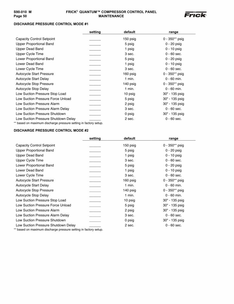
S90-010 M FRICK QUANTUM™ COMPRESSOR CONTROL PANELPage 50 MAINTENANCE
DISCHARGE PRESSURE CONTROL MODE #1
setting default range
Capacity Control Setpoint ______ 150 psig 0 - 350** psigUpper Proportional Band ______ 5 psig 0 - 20 psigUpper Dead Band ______ 1 psig 0 - 10 psigUpper Cycle Time ______ 3 sec. 0 - 60 sec.Lower Proportional Band ______ 5 psig 0 - 20 psigLower Dead Band ______ 1 psig 0 - 10 psigLower Cycle Time ______ 3 sec. 0 - 60 sec.Autocycle Start Pressure ______ 160 psig 0 - 350** psigAutocycle Start Delay ______ 1 min. 0 - 60 min.Autocycle Stop Pressure ______ 140 psig 0 - 350** psigAutocycle Stop Delay ______ 1 min. 0 - 60 min.Low Suction Pressure Stop Load ______ 10 psig 30" - 135 psigLow Suction Pressure Force Unload ______ 5 psig 30" - 135 psigLow Suction Pressure Alarm ______ 2 psig 30" - 135 psigLow Suction Pressure Alarm Delay ______ 3 sec. 0 - 60 sec.Low Suction Pressure Shutdown ______ 0 psig 30" - 135 psigLow Suction Pressure Shutdown Delay ______ 2 sec. 0 - 60 sec.
** based on maximum discharge pressure setting in factory setup.
DISCHARGE PRESSURE CONTROL MODE #2
setting default range
Capacity Control Setpoint ______ 150 psig 0 - 350** psigUpper Proportional Band ______ 5 psig 0 - 20 psigUpper Dead Band ______ 1 psig 0 - 10 psigUpper Cycle Time ______ 3 sec. 0 - 60 sec.Lower Proportional Band ______ 5 psig 0 - 20 psigLower Dead Band ______ 1 psig 0 - 10 psigLower Cycle Time ______ 3 sec. 0 - 60 sec.Autocycle Start Pressure ______ 160 psig 0 - 350** psigAutocycle Start Delay ______ 1 min. 0 - 60 min.Autocycle Stop Pressure ______ 140 psig 0 - 350** psigAutocycle Stop Delay ______ 1 min. 0 - 60 min.Low Suction Pressure Stop Load ______ 10 psig 30" - 135 psigLow Suction Pressure Force Unload ______ 5 psig 30" - 135 psigLow Suction Pressure Alarm ______ 2 psig 30" - 135 psigLow Suction Pressure Alarm Delay ______ 3 sec. 0 - 60 sec.Low Suction Pressure Shutdown ______ 0 psig 30" - 135 psigLow Suction Pressure Shutdown Delay ______ 2 sec. 0 - 60 sec.
** based on maximum discharge pressure setting in factory setup.
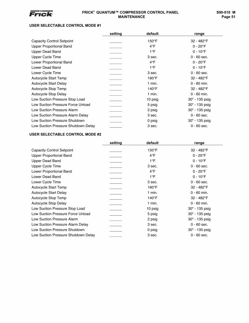
FRICK QUANTUM™ COMPRESSOR CONTROL PANEL S90-010 M MAINTENANCE Page 51
USER SELECTABLE CONTROL MODE #1
setting default range
Capacity Control Setpoint ______ 150°F 32 - 482°FUpper Proportional Band ______ 4°F 0 - 20°FUpper Dead Band ______ 1°F 0 - 10°FUpper Cycle Time ______ 3 sec. 0 - 60 sec.Lower Proportional Band ______ 4°F 0 - 20°FLower Dead Band ______ 1°F 0 - 10°FLower Cycle Time ______ 3 sec. 0 - 60 sec.Autocycle Start Temp ______ 160°F 32 - 482°FAutocycle Start Delay ______ 1 min. 0 - 60 min.Autocycle Stop Temp ______ 140°F 32 - 482°FAutocycle Stop Delay ______ 1 min. 0 - 60 min.Low Suction Pressure Stop Load ______ 10 psig 30" - 135 psigLow Suction Pressure Force Unload ______ 5 psig 30" - 135 psigLow Suction Pressure Alarm ______ 2 psig 30" - 135 psigLow Suction Pressure Alarm Delay ______ 3 sec. 0 - 60 sec.Low Suction Pressure Shutdown ______ 0 psig 30" - 135 psigLow Suction Pressure Shutdown Delay ______ 3 sec. 0 - 60 sec.
USER SELECTABLE CONTROL MODE #2
setting default range
Capacity Control Setpoint ______ 150°F 32 - 482°FUpper Proportional Band ______ 4°F 0 - 20°FUpper Dead Band ______ 1°F 0 - 10°FUpper Cycle Time ______ 3 sec. 0 - 60 sec.Lower Proportional Band ______ 4°F 0 - 20°FLower Dead Band ______ 1°F 0 - 10°FLower Cycle Time ______ 3 sec. 0 - 60 sec.Autocycle Start Temp ______ 160°F 32 - 482°FAutocycle Start Delay ______ 1 min. 0 - 60 min.Autocycle Stop Temp ______ 140°F 32 - 482°FAutocycle Stop Delay ______ 1 min. 0 - 60 min.Low Suction Pressure Stop Load ______ 10 psig 30" - 135 psigLow Suction Pressure Force Unload ______ 5 psig 30" - 135 psigLow Suction Pressure Alarm ______ 2 psig 30" - 135 psigLow Suction Pressure Alarm Delay ______ 3 sec. 0 - 60 sec.Low Suction Pressure Shutdown ______ 0 psig 30" - 135 psigLow Suction Pressure Shutdown Delay ______ 3 sec. 0 - 60 sec.
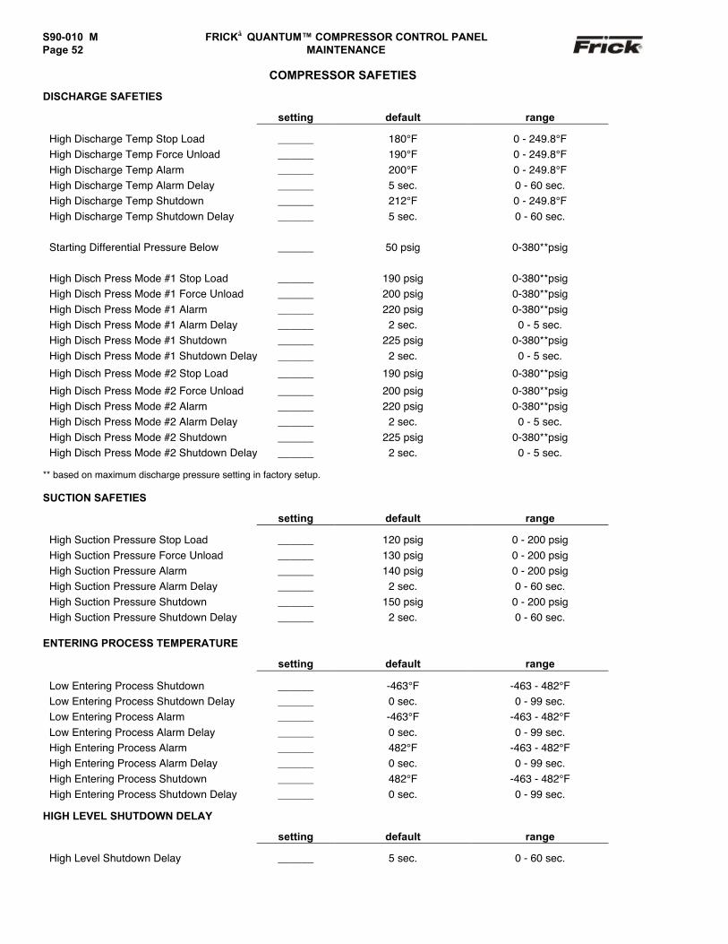
S90-010 M FRICK QUANTUM™ COMPRESSOR CONTROL PANELPage 52 MAINTENANCE
COMPRESSOR SAFETIES
DISCHARGE SAFETIES
setting default range
High Discharge Temp Stop Load ______ 180°F 0 - 249.8°FHigh Discharge Temp Force Unload ______ 190°F 0 - 249.8°FHigh Discharge Temp Alarm ______ 200°F 0 - 249.8°FHigh Discharge Temp Alarm Delay ______ 5 sec. 0 - 60 sec.High Discharge Temp Shutdown ______ 212°F 0 - 249.8°FHigh Discharge Temp Shutdown Delay ______ 5 sec. 0 - 60 sec.
Starting Differential Pressure Below ______ 50 psig 0-380**psig
High Disch Press Mode #1 Stop Load ______ 190 psig 0-380**psigHigh Disch Press Mode #1 Force Unload ______ 200 psig 0-380**psigHigh Disch Press Mode #1 Alarm ______ 220 psig 0-380**psigHigh Disch Press Mode #1 Alarm Delay ______ 2 sec. 0 - 5 sec.High Disch Press Mode #1 Shutdown ______ 225 psig 0-380**psigHigh Disch Press Mode #1 Shutdown Delay ______ 2 sec. 0 - 5 sec.
High Disch Press Mode #2 Stop Load ______ 190 psig 0-380**psig
High Disch Press Mode #2 Force Unload ______ 200 psig 0-380**psigHigh Disch Press Mode #2 Alarm ______ 220 psig 0-380**psigHigh Disch Press Mode #2 Alarm Delay ______ 2 sec. 0 - 5 sec.High Disch Press Mode #2 Shutdown ______ 225 psig 0-380**psigHigh Disch Press Mode #2 Shutdown Delay ______ 2 sec. 0 - 5 sec.
** based on maximum discharge pressure setting in factory setup.
SUCTION SAFETIES
setting default range
High Suction Pressure Stop Load ______ 120 psig 0 - 200 psigHigh Suction Pressure Force Unload ______ 130 psig 0 - 200 psigHigh Suction Pressure Alarm ______ 140 psig 0 - 200 psigHigh Suction Pressure Alarm Delay ______ 2 sec. 0 - 60 sec.High Suction Pressure Shutdown ______ 150 psig 0 - 200 psigHigh Suction Pressure Shutdown Delay ______ 2 sec. 0 - 60 sec.
ENTERING PROCESS TEMPERATURE
setting default range
Low Entering Process Shutdown ______ -463°F -463 - 482°FLow Entering Process Shutdown Delay ______ 0 sec. 0 - 99 sec.Low Entering Process Alarm ______ -463°F -463 - 482°FLow Entering Process Alarm Delay ______ 0 sec. 0 - 99 sec.High Entering Process Alarm ______ 482°F -463 - 482°FHigh Entering Process Alarm Delay ______ 0 sec. 0 - 99 sec.High Entering Process Shutdown ______ 482°F -463 - 482°FHigh Entering Process Shutdown Delay ______ 0 sec. 0 - 99 sec.
HIGH LEVEL SHUTDOWN DELAY
setting default range
High Level Shutdown Delay ______ 5 sec. 0 - 60 sec.
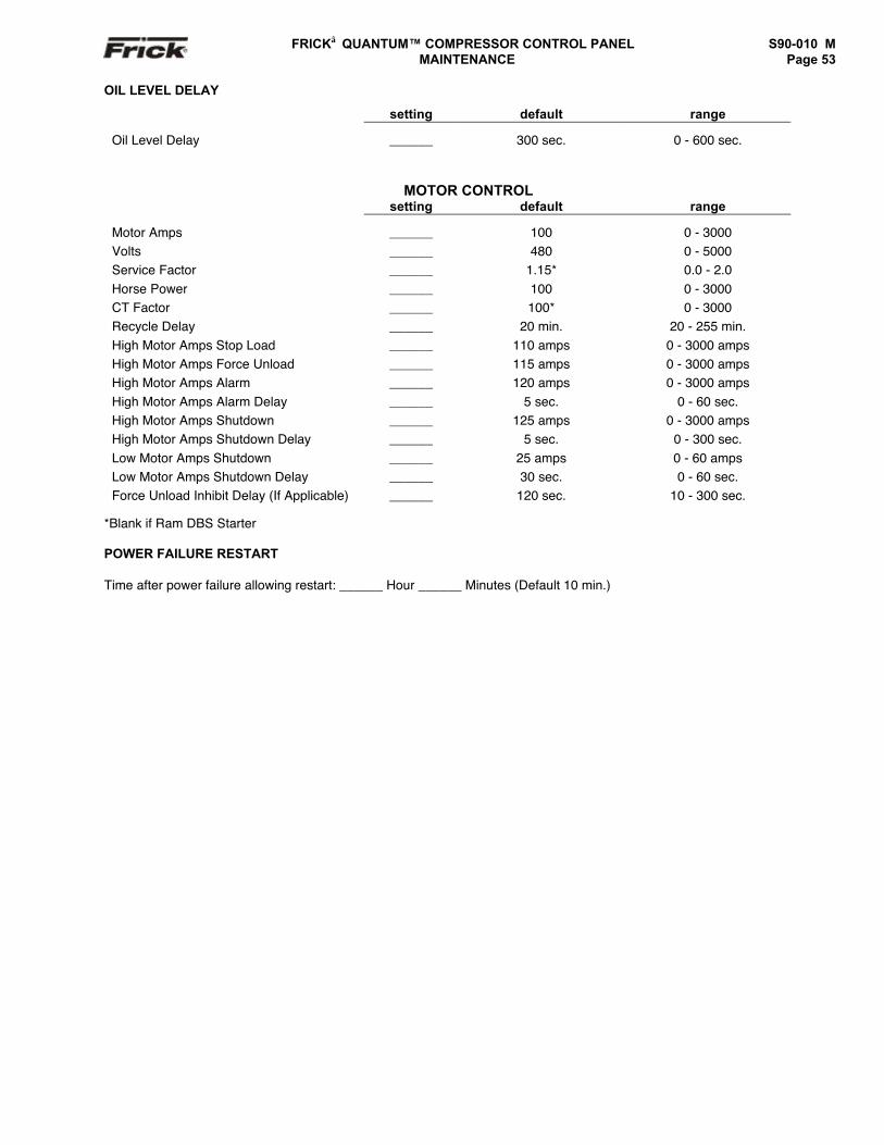
FRICK QUANTUM™ COMPRESSOR CONTROL PANEL S90-010 M MAINTENANCE Page 53
OIL LEVEL DELAY
setting default range
Oil Level Delay ______ 300 sec. 0 - 600 sec.
MOTOR CONTROLsetting default range
Motor Amps ______ 100 0 - 3000Volts ______ 480 0 - 5000Service Factor ______ 1.15* 0.0 - 2.0Horse Power ______ 100 0 - 3000CT Factor ______ 100* 0 - 3000Recycle Delay ______ 20 min. 20 - 255 min.High Motor Amps Stop Load ______ 110 amps 0 - 3000 ampsHigh Motor Amps Force Unload ______ 115 amps 0 - 3000 ampsHigh Motor Amps Alarm ______ 120 amps 0 - 3000 ampsHigh Motor Amps Alarm Delay ______ 5 sec. 0 - 60 sec.High Motor Amps Shutdown ______ 125 amps 0 - 3000 ampsHigh Motor Amps Shutdown Delay ______ 5 sec. 0 - 300 sec.Low Motor Amps Shutdown ______ 25 amps 0 - 60 ampsLow Motor Amps Shutdown Delay ______ 30 sec. 0 - 60 sec.Force Unload Inhibit Delay (If Applicable) ______ 120 sec. 10 - 300 sec.
*Blank if Ram DBS Starter
POWER FAILURE RESTART
Time after power failure allowing restart: ______ Hour ______ Minutes (Default 10 min.)
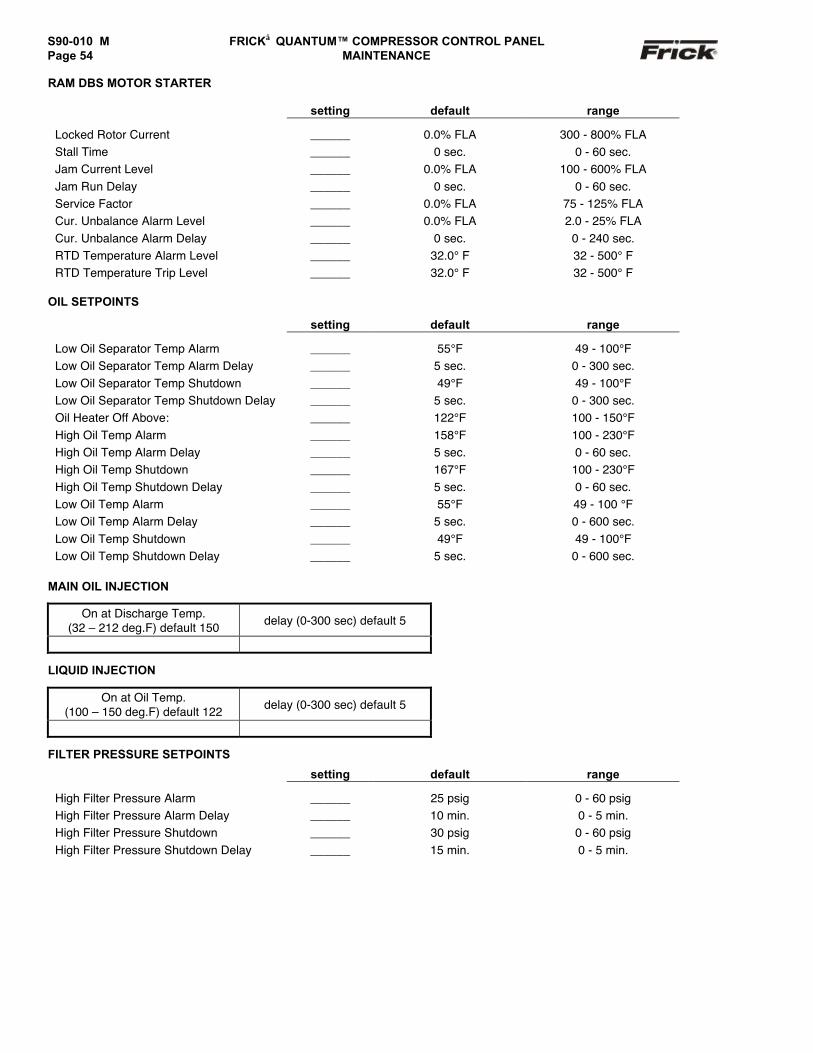
S90-010 M FRICK QUANTUM™ COMPRESSOR CONTROL PANELPage 54 MAINTENANCE
RAM DBS MOTOR STARTER
setting default range
Locked Rotor Current ______ 0.0% FLA 300 - 800% FLAStall Time ______ 0 sec. 0 - 60 sec.Jam Current Level ______ 0.0% FLA 100 - 600% FLAJam Run Delay ______ 0 sec. 0 - 60 sec.Service Factor ______ 0.0% FLA 75 - 125% FLACur. Unbalance Alarm Level ______ 0.0% FLA 2.0 - 25% FLACur. Unbalance Alarm Delay ______ 0 sec. 0 - 240 sec.RTD Temperature Alarm Level ______ 32.0° F 32 - 500° FRTD Temperature Trip Level ______ 32.0° F 32 - 500° F
OIL SETPOINTS
setting default range
Low Oil Separator Temp Alarm ______ 55°F 49 - 100°FLow Oil Separator Temp Alarm Delay ______ 5 sec. 0 - 300 sec.Low Oil Separator Temp Shutdown ______ 49°F 49 - 100°FLow Oil Separator Temp Shutdown Delay ______ 5 sec. 0 - 300 sec.Oil Heater Off Above: ______ 122°F 100 - 150°FHigh Oil Temp Alarm ______ 158°F 100 - 230°FHigh Oil Temp Alarm Delay ______ 5 sec. 0 - 60 sec.High Oil Temp Shutdown ______ 167°F 100 - 230°FHigh Oil Temp Shutdown Delay ______ 5 sec. 0 - 60 sec.Low Oil Temp Alarm ______ 55°F 49 - 100 °FLow Oil Temp Alarm Delay ______ 5 sec. 0 - 600 sec.Low Oil Temp Shutdown ______ 49°F 49 - 100°FLow Oil Temp Shutdown Delay ______ 5 sec. 0 - 600 sec.
MAIN OIL INJECTION
On at Discharge Temp.(32 – 212 deg.F) default 150 delay (0-300 sec) default 5
LIQUID INJECTION
On at Oil Temp.(100 – 150 deg.F) default 122 delay (0-300 sec) default 5
FILTER PRESSURE SETPOINTS
setting default range
High Filter Pressure Alarm ______ 25 psig 0 - 60 psigHigh Filter Pressure Alarm Delay ______ 10 min. 0 - 5 min.High Filter Pressure Shutdown ______ 30 psig 0 - 60 psigHigh Filter Pressure Shutdown Delay ______ 15 min. 0 - 5 min.
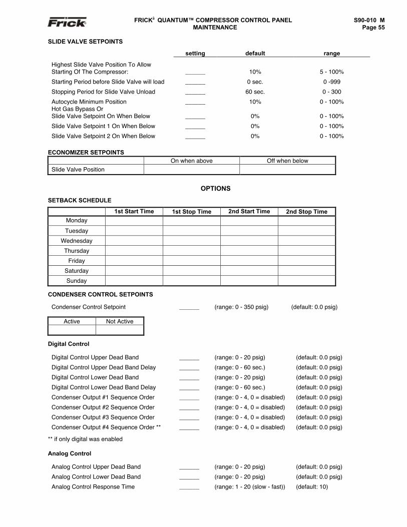
FRICK QUANTUM™ COMPRESSOR CONTROL PANEL S90-010 M MAINTENANCE Page 55
SLIDE VALVE SETPOINTS
setting default range
Highest Slide Valve Position To AllowStarting Of The Compressor: ______ 10% 5 - 100%
Starting Period before Slide Valve will load ______ 0 sec. 0 -999
Stopping Period for Slide Valve Unload ______ 60 sec. 0 - 300
Autocycle Minimum Position ______ 10% 0 - 100%Hot Gas Bypass OrSlide Valve Setpoint On When Below ______ 0% 0 - 100%
Slide Valve Setpoint 1 On When Below ______ 0% 0 - 100%
Slide Valve Setpoint 2 On When Below ______ 0% 0 - 100%
ECONOMIZER SETPOINTSOn when above Off when below
Slide Valve Position
OPTIONS
SETBACK SCHEDULE
1st Start Time 1st Stop Time 2nd Start Time 2nd Stop TimeMonday
Tuesday
Wednesday
Thursday
Friday
Saturday
Sunday
CONDENSER CONTROL SETPOINTS
Condenser Control Setpoint ______ (range: 0 - 350 psig) (default: 0.0 psig)
Active Not Active
Digital Control
Digital Control Upper Dead Band ______ (range: 0 - 20 psig) (default: 0.0 psig)
Digital Control Upper Dead Band Delay ______ (range: 0 - 60 sec.) (default: 0.0 psig)
Digital Control Lower Dead Band ______ (range: 0 - 20 psig) (default: 0.0 psig)
Digital Control Lower Dead Band Delay ______ (range: 0 - 60 sec.) (default: 0.0 psig)
Condenser Output #1 Sequence Order ______ (range: 0 - 4, 0 = disabled) (default: 0.0 psig)
Condenser Output #2 Sequence Order ______ (range: 0 - 4, 0 = disabled) (default: 0.0 psig)
Condenser Output #3 Sequence Order ______ (range: 0 - 4, 0 = disabled) (default: 0.0 psig)
Condenser Output #4 Sequence Order ** ______ (range: 0 - 4, 0 = disabled) (default: 0.0 psig)
** if only digital was enabled
Analog Control
Analog Control Upper Dead Band ______ (range: 0 - 20 psig) (default: 0.0 psig)
Analog Control Lower Dead Band ______ (range: 0 - 20 psig) (default: 0.0 psig)
Analog Control Response Time ______ (range: 1 - 20 (slow - fast)) (default: 10)
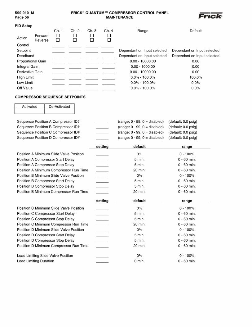
S90-010 M FRICK QUANTUM™ COMPRESSOR CONTROL PANELPage 56 MAINTENANCE
PID SetupCh. 1 Ch. 2 Ch. 3 Ch. 4 Range Default
ForwardAction ReverseControl ______ ______ ______ ______Setpoint ______ ______ ______ ______ Dependant on Input selected Dependant on Input selectedDeadband ______ ______ ______ ______ Dependant on Input selected Dependant on Input selectedProportional Gain ______ ______ ______ ______ 0.00 - 10000.00 0.00Integral Gain ______ ______ ______ ______ 0.00 - 1000.00 0.00Derivative Gain ______ ______ ______ ______ 0.00 - 10000.00 0.00High Limit ______ ______ ______ ______ 0.0% - 100.0% 100.0%Low Limit ______ ______ ______ ______ 0.0% - 100.0% 0.0%Off Value ______ ______ ______ ______ 0.0% - 100.0% 0.0%
COMPRESSOR SEQUENCE SETPOINTS
Activated De-Activated
Sequence Position A Compressor ID# ______ (range: 0 - 99, 0 = disabled) (default: 0.0 psig)Sequence Position B Compressor ID# ______ (range: 0 - 99, 0 = disabled) (default: 0.0 psig)Sequence Position C Compressor ID# ______ (range: 0 - 99, 0 = disabled) (default: 0.0 psig)Sequence Position D Compressor ID# ______ (range: 0 - 99, 0 = disabled) (default: 0.0 psig)
setting default range
Position A Minimum Slide Valve Position ______ 0% 0 - 100%Position A Compressor Start Delay ______ 5 min. 0 - 60 min.Position A Compressor Stop Delay ______ 5 min. 0 - 60 min.Position A Minimum Compressor Run Time ______ 20 min. 0 - 60 min.Position B Minimum Slide Valve Position ______ 0% 0 - 100%Position B Compressor Start Delay ______ 5 min. 0 - 60 min.Position B Compressor Stop Delay ______ 5 min. 0 - 60 min.Position B Minimum Compressor Run Time ______ 20 min. 0 - 60 min.
setting default range
Position C Minimum Slide Valve Position ______ 0% 0 - 100%Position C Compressor Start Delay ______ 5 min. 0 - 60 min.Position C Compressor Stop Delay ______ 5 min. 0 - 60 min.Position C Minimum Compressor Run Time ______ 20 min. 0 - 60 min.Position D Minimum Slide Valve Position ______ 0% 0 - 100%Position D Compressor Start Delay ______ 5 min. 0 - 60 min.Position D Compressor Stop Delay ______ 5 min. 0 - 60 min.Position D Minimum Compressor Run Time ______ 20 min. 0 - 60 min.
Load Limiting Slide Valve Position ______ 0% 0 - 100%Load Limiting Duration ______ 0 min. 0 - 60 min.
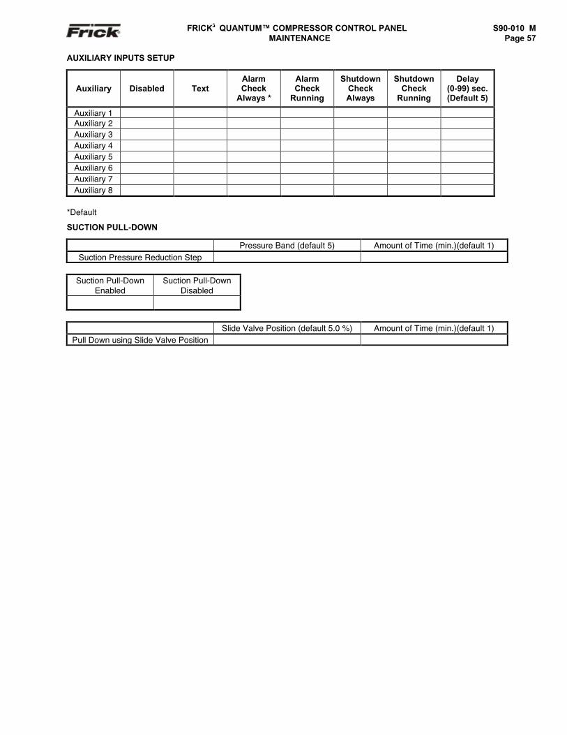
FRICK QUANTUM™ COMPRESSOR CONTROL PANEL S90-010 M MAINTENANCE Page 57
AUXILIARY INPUTS SETUP
Auxiliary Disabled TextAlarmCheck
Always *
AlarmCheck
Running
ShutdownCheckAlways
ShutdownCheck
Running
Delay(0-99) sec.(Default 5)
Auxiliary 1Auxiliary 2Auxiliary 3Auxiliary 4Auxiliary 5Auxiliary 6Auxiliary 7Auxiliary 8
*Default
SUCTION PULL-DOWN
Pressure Band (default 5) Amount of Time (min.)(default 1)Suction Pressure Reduction Step
Suction Pull-DownEnabled
Suction Pull-DownDisabled
Slide Valve Position (default 5.0 %) Amount of Time (min.)(default 1)Pull Down using Slide Valve Position
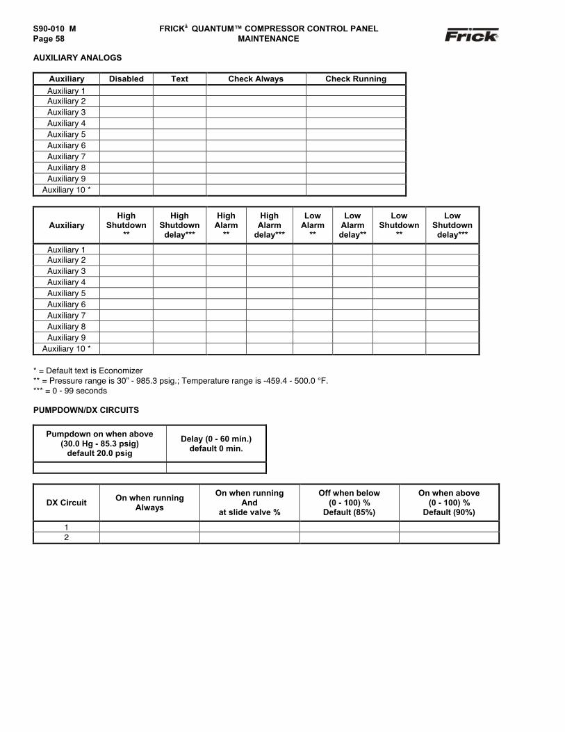
S90-010 M FRICK QUANTUM™ COMPRESSOR CONTROL PANELPage 58 MAINTENANCE
AUXILIARY ANALOGS
Auxiliary Disabled Text Check Always Check RunningAuxiliary 1Auxiliary 2Auxiliary 3Auxiliary 4Auxiliary 5Auxiliary 6Auxiliary 7Auxiliary 8Auxiliary 9
Auxiliary 10 *
AuxiliaryHigh
Shutdown**
HighShutdown
delay***
HighAlarm
**
HighAlarm
delay***
LowAlarm
**
LowAlarmdelay**
LowShutdown
**
LowShutdown
delay***
Auxiliary 1Auxiliary 2Auxiliary 3Auxiliary 4Auxiliary 5Auxiliary 6Auxiliary 7Auxiliary 8Auxiliary 9
Auxiliary 10 *
* = Default text is Economizer** = Pressure range is 30” - 985.3 psig.; Temperature range is -459.4 - 500.0 °F.*** = 0 - 99 seconds
PUMPDOWN/DX CIRCUITS
Pumpdown on when above(30.0 Hg - 85.3 psig)
default 20.0 psig
Delay (0 - 60 min.)default 0 min.
DX Circuit On when runningAlways
On when runningAnd
at slide valve %
Off when below(0 - 100) %
Default (85%)
On when above(0 - 100) %
Default (90%)
12
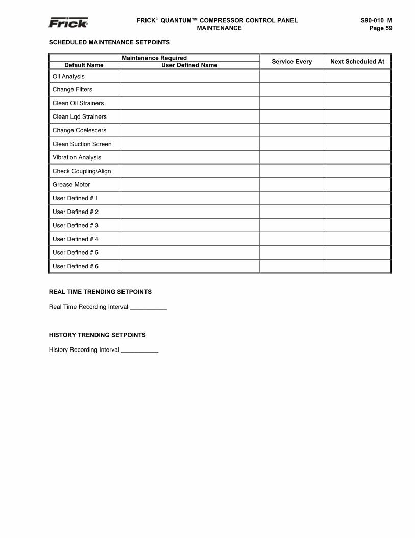
FRICK QUANTUM™ COMPRESSOR CONTROL PANEL S90-010 M MAINTENANCE Page 59
SCHEDULED MAINTENANCE SETPOINTS
Maintenance RequiredDefault Name User Defined Name Service Every Next Scheduled At
Oil Analysis
Change Filters
Clean Oil Strainers
Clean Lqd Strainers
Change Coelescers
Clean Suction Screen
Vibration Analysis
Check Coupling/Align
Grease Motor
User Defined # 1
User Defined # 2
User Defined # 3
User Defined # 4
User Defined # 5
User Defined # 6
REAL TIME TRENDING SETPOINTS
Real Time Recording Interval ___________
HISTORY TRENDING SETPOINTS
History Recording Interval ___________
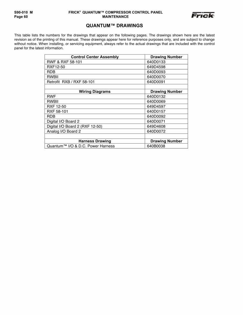
S90-010 M FRICK QUANTUM™ COMPRESSOR CONTROL PANELPage 60 MAINTENANCE
QUANTUM™ DRAWINGS
This table lists the numbers for the drawings that appear on the following pages. The drawings shown here are the latestrevision as of the printing of this manual. These drawings appear here for reference purposes only, and are subject to changewithout notice. When installing, or servicing equipment, always refer to the actual drawings that are included with the controlpanel for the latest information.
Control Center Assembly Drawing NumberRWF & RXF 58-101 640D0133RXF12-50 649D4598RDB 640D0093RWBII 640D0070Retrofit RXB / RXF 58-101 640D0091
Wiring Diagrams Drawing NumberRWF 640D0132RWBII 640D0069RXF 12-50 649D4597RXF 58-101 640D0157RDB 640D0092Digital I/O Board 2 640D0071Digital I/O Board 2 (RXF 12-50) 649D4608Analog I/O Board 2 640D0072
Harness Drawing Drawing NumberQuantum™ I/O & D.C. Power Harness 640B0038
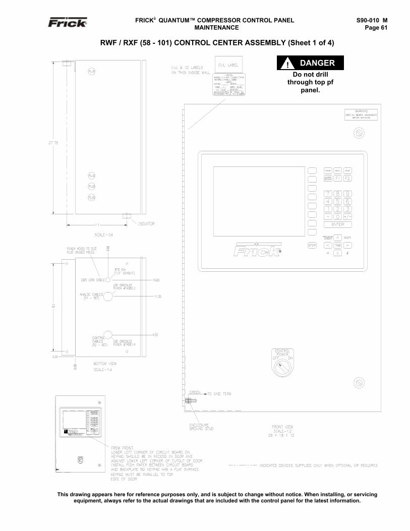
FRICK QUANTUM™ COMPRESSOR CONTROL PANEL S90-010 M MAINTENANCE Page 61
RWF / RXF (58 - 101) CONTROL CENTER ASSEMBLY (Sheet 1 of 4)
This drawing appears here for reference purposes only, and is subject to change without notice. When installing, or servicingequipment, always refer to the actual drawings that are included with the control panel for the latest information.
Do not drillthrough top pf
panel.
DANGER!
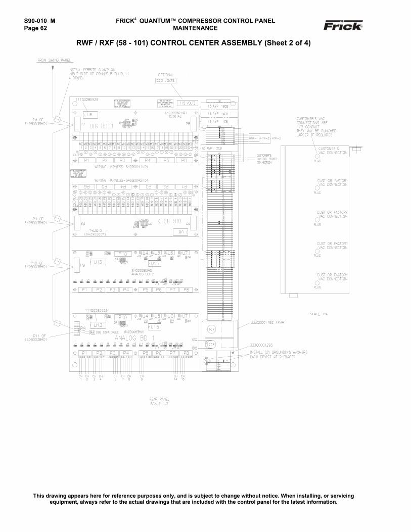
S90-010 M FRICK QUANTUM™ COMPRESSOR CONTROL PANELPage 62 MAINTENANCE
RWF / RXF (58 - 101) CONTROL CENTER ASSEMBLY (Sheet 2 of 4)
This drawing appears here for reference purposes only, and is subject to change without notice. When installing, or servicingequipment, always refer to the actual drawings that are included with the control panel for the latest information.
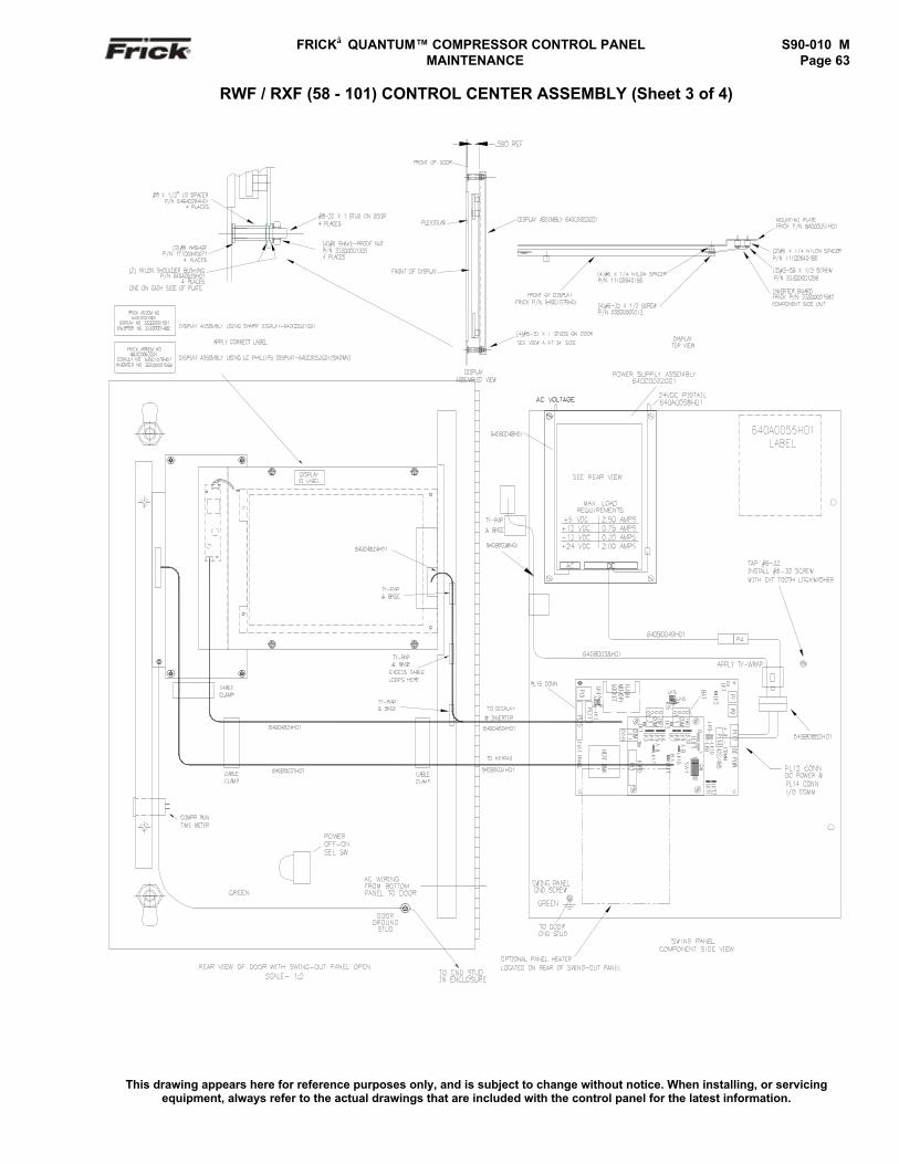
FRICK QUANTUM™ COMPRESSOR CONTROL PANEL S90-010 M MAINTENANCE Page 63
RWF / RXF (58 - 101) CONTROL CENTER ASSEMBLY (Sheet 3 of 4)
This drawing appears here for reference purposes only, and is subject to change without notice. When installing, or servicingequipment, always refer to the actual drawings that are included with the control panel for the latest information.
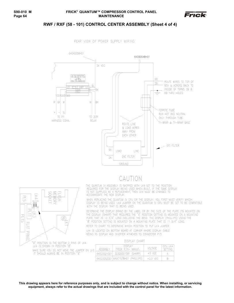
S90-010 M FRICK QUANTUM™ COMPRESSOR CONTROL PANELPage 64 MAINTENANCE
RWF / RXF (58 - 101) CONTROL CENTER ASSEMBLY (Sheet 4 of 4)
This drawing appears here for reference purposes only, and is subject to change without notice. When installing, or servicingequipment, always refer to the actual drawings that are included with the control panel for the latest information.
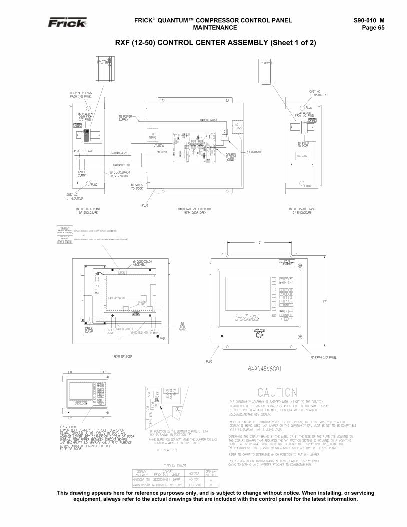
FRICK QUANTUM™ COMPRESSOR CONTROL PANEL S90-010 M MAINTENANCE Page 65
RXF (12-50) CONTROL CENTER ASSEMBLY (Sheet 1 of 2)
This drawing appears here for reference purposes only, and is subject to change without notice. When installing, or servicingequipment, always refer to the actual drawings that are included with the control panel for the latest information.
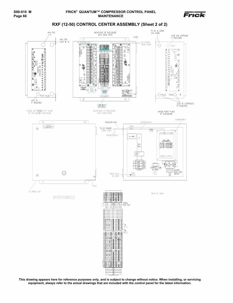
S90-010 M FRICK QUANTUM™ COMPRESSOR CONTROL PANELPage 66 MAINTENANCE
RXF (12-50) CONTROL CENTER ASSEMBLY (Sheet 2 of 2)
This drawing appears here for reference purposes only, and is subject to change without notice. When installing, or servicingequipment, always refer to the actual drawings that are included with the control panel for the latest information.
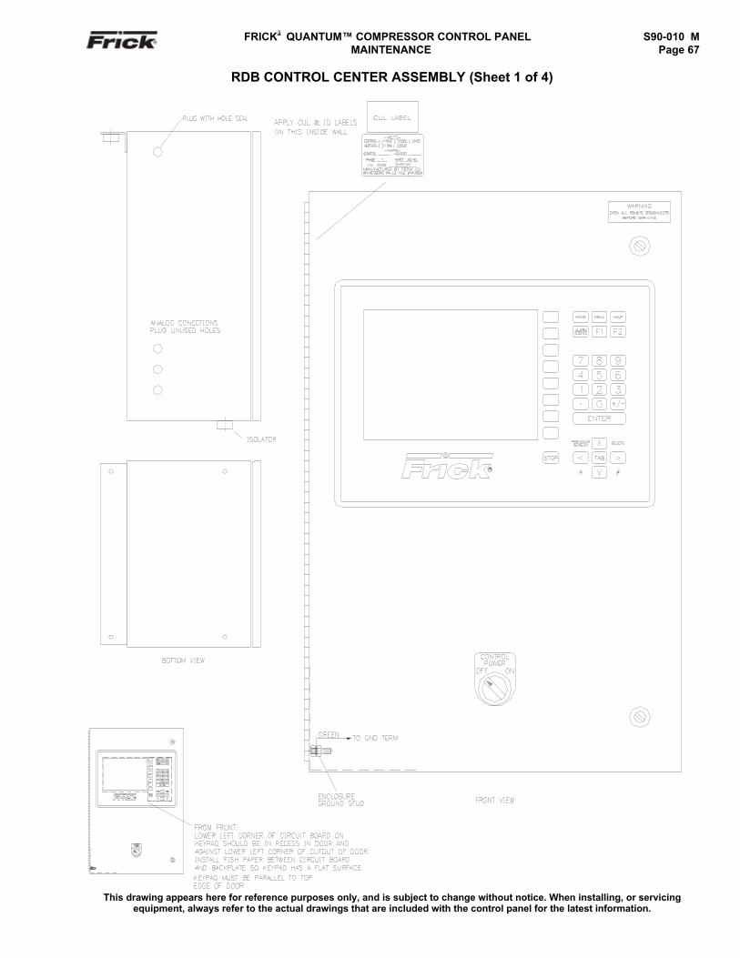
FRICK QUANTUM™ COMPRESSOR CONTROL PANEL S90-010 M MAINTENANCE Page 67
RDB CONTROL CENTER ASSEMBLY (Sheet 1 of 4)
This drawing appears here for reference purposes only, and is subject to change without notice. When installing, or servicingequipment, always refer to the actual drawings that are included with the control panel for the latest information.
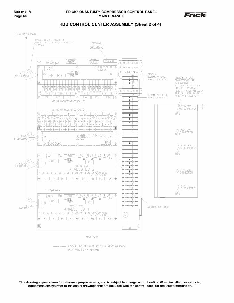
S90-010 M FRICK QUANTUM™ COMPRESSOR CONTROL PANELPage 68 MAINTENANCE
RDB CONTROL CENTER ASSEMBLY (Sheet 2 of 4)
This drawing appears here for reference purposes only, and is subject to change without notice. When installing, or servicingequipment, always refer to the actual drawings that are included with the control panel for the latest information.
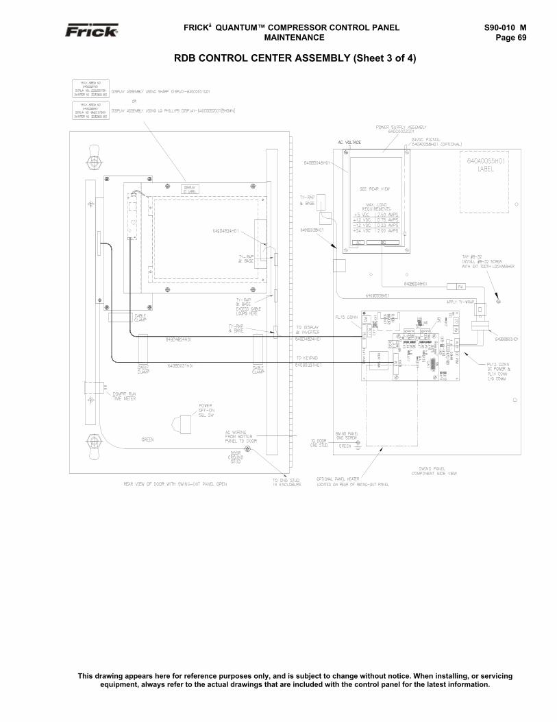
FRICK QUANTUM™ COMPRESSOR CONTROL PANEL S90-010 M MAINTENANCE Page 69
RDB CONTROL CENTER ASSEMBLY (Sheet 3 of 4)
This drawing appears here for reference purposes only, and is subject to change without notice. When installing, or servicingequipment, always refer to the actual drawings that are included with the control panel for the latest information.
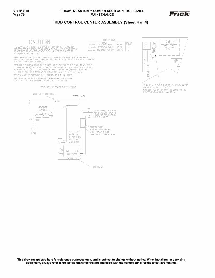
S90-010 M FRICK QUANTUM™ COMPRESSOR CONTROL PANELPage 70 MAINTENANCE
RDB CONTROL CENTER ASSEMBLY (Sheet 4 of 4)
This drawing appears here for reference purposes only, and is subject to change without notice. When installing, or servicingequipment, always refer to the actual drawings that are included with the control panel for the latest information.
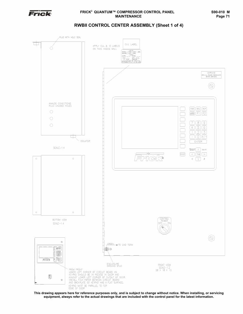
FRICK QUANTUM™ COMPRESSOR CONTROL PANEL S90-010 M MAINTENANCE Page 71
RWBII CONTROL CENTER ASSEMBLY (Sheet 1 of 4)
This drawing appears here for reference purposes only, and is subject to change without notice. When installing, or servicingequipment, always refer to the actual drawings that are included with the control panel for the latest information.
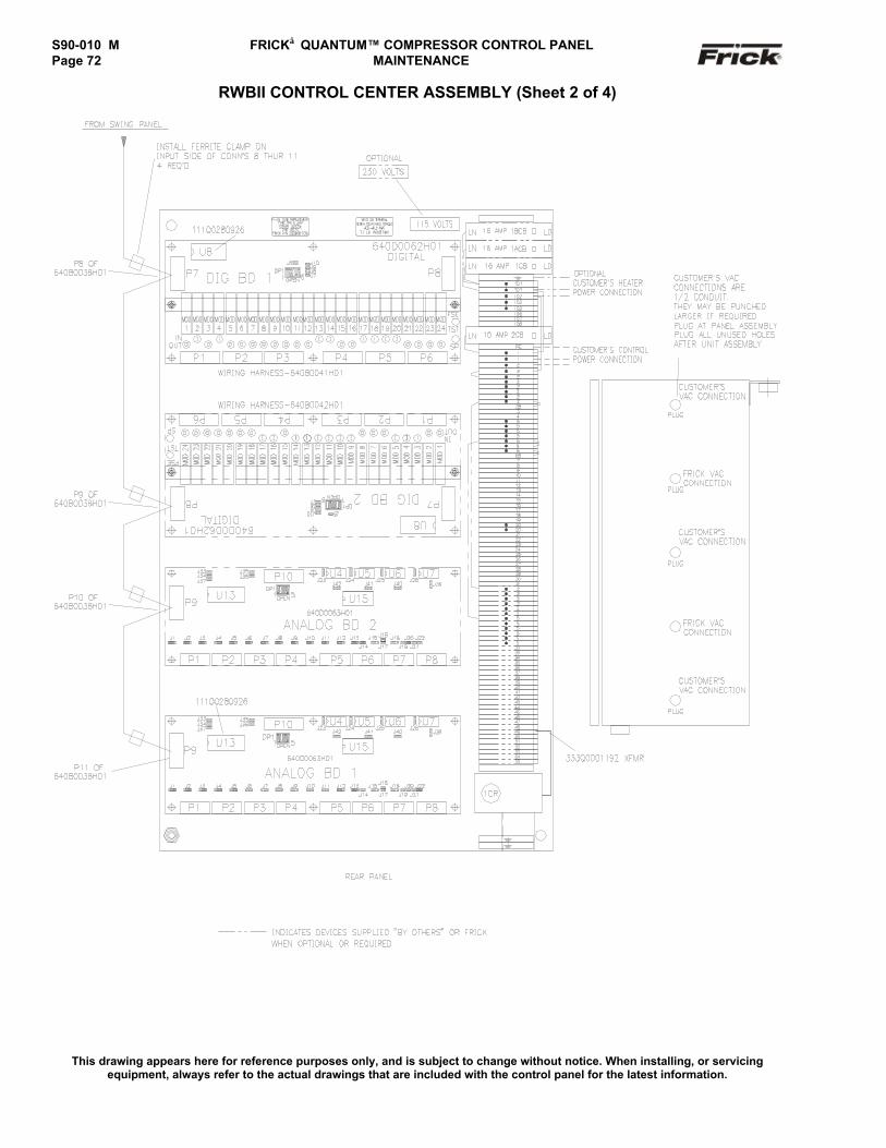
S90-010 M FRICK QUANTUM™ COMPRESSOR CONTROL PANELPage 72 MAINTENANCE
RWBII CONTROL CENTER ASSEMBLY (Sheet 2 of 4)
This drawing appears here for reference purposes only, and is subject to change without notice. When installing, or servicingequipment, always refer to the actual drawings that are included with the control panel for the latest information.
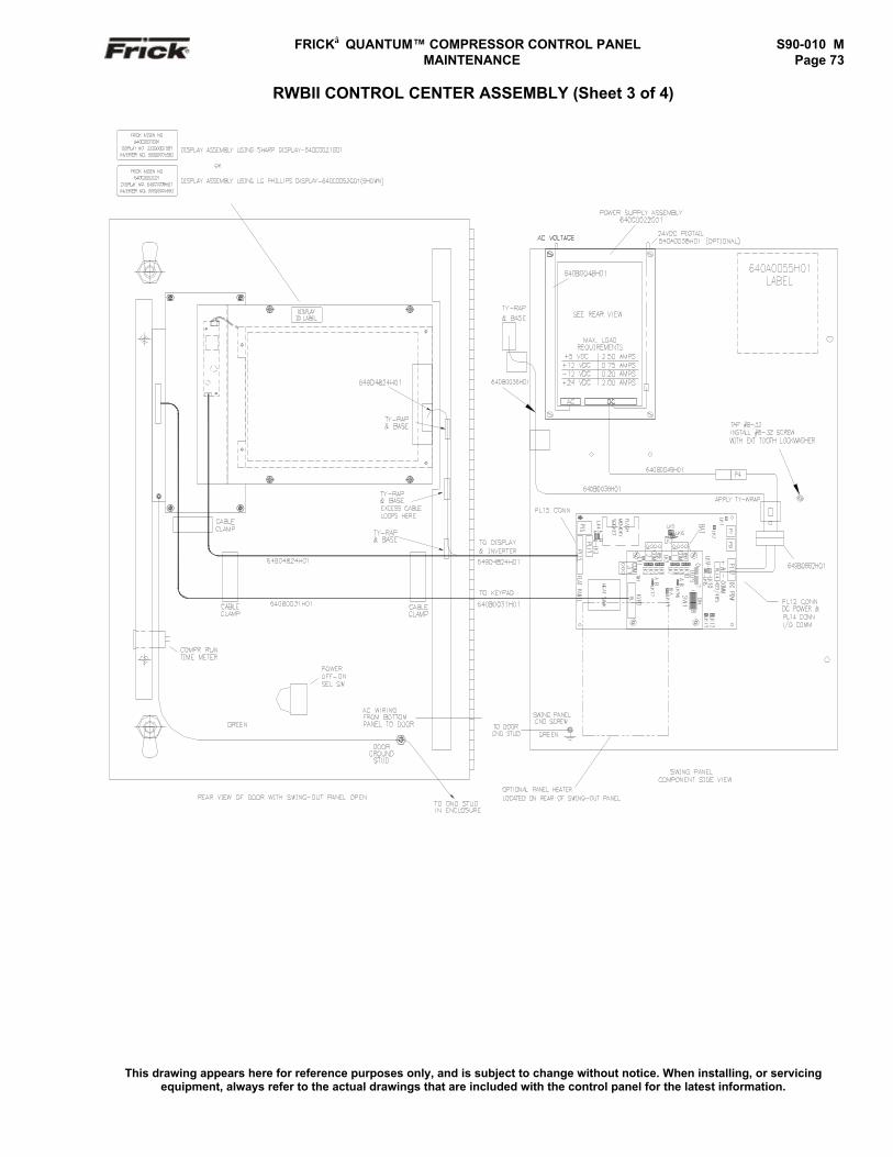
FRICK QUANTUM™ COMPRESSOR CONTROL PANEL S90-010 M MAINTENANCE Page 73
RWBII CONTROL CENTER ASSEMBLY (Sheet 3 of 4)
This drawing appears here for reference purposes only, and is subject to change without notice. When installing, or servicingequipment, always refer to the actual drawings that are included with the control panel for the latest information.
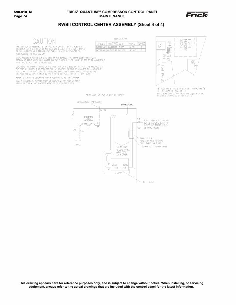
S90-010 M FRICK QUANTUM™ COMPRESSOR CONTROL PANELPage 74 MAINTENANCE
RWBII CONTROL CENTER ASSEMBLY (Sheet 4 of 4)
This drawing appears here for reference purposes only, and is subject to change without notice. When installing, or servicingequipment, always refer to the actual drawings that are included with the control panel for the latest information.
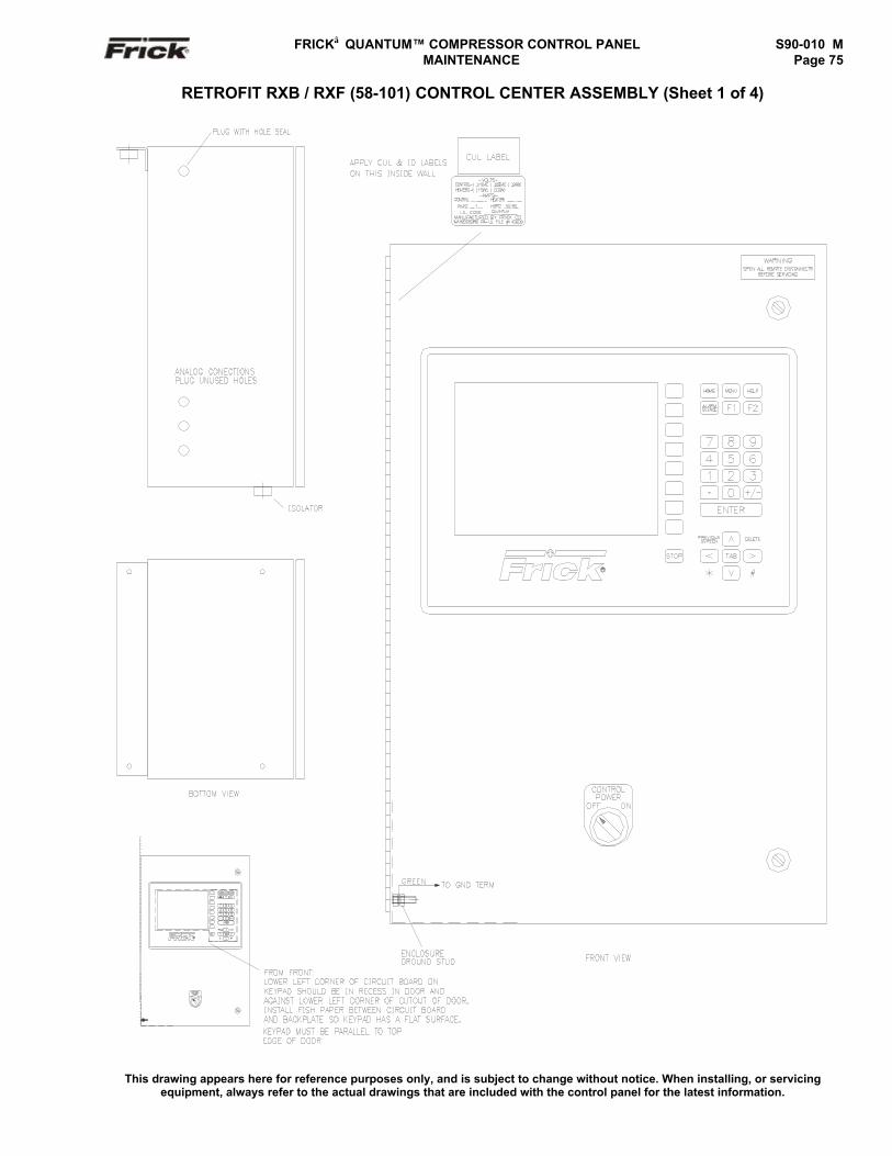
FRICK QUANTUM™ COMPRESSOR CONTROL PANEL S90-010 M MAINTENANCE Page 75
RETROFIT RXB / RXF (58-101) CONTROL CENTER ASSEMBLY (Sheet 1 of 4)
This drawing appears here for reference purposes only, and is subject to change without notice. When installing, or servicingequipment, always refer to the actual drawings that are included with the control panel for the latest information.
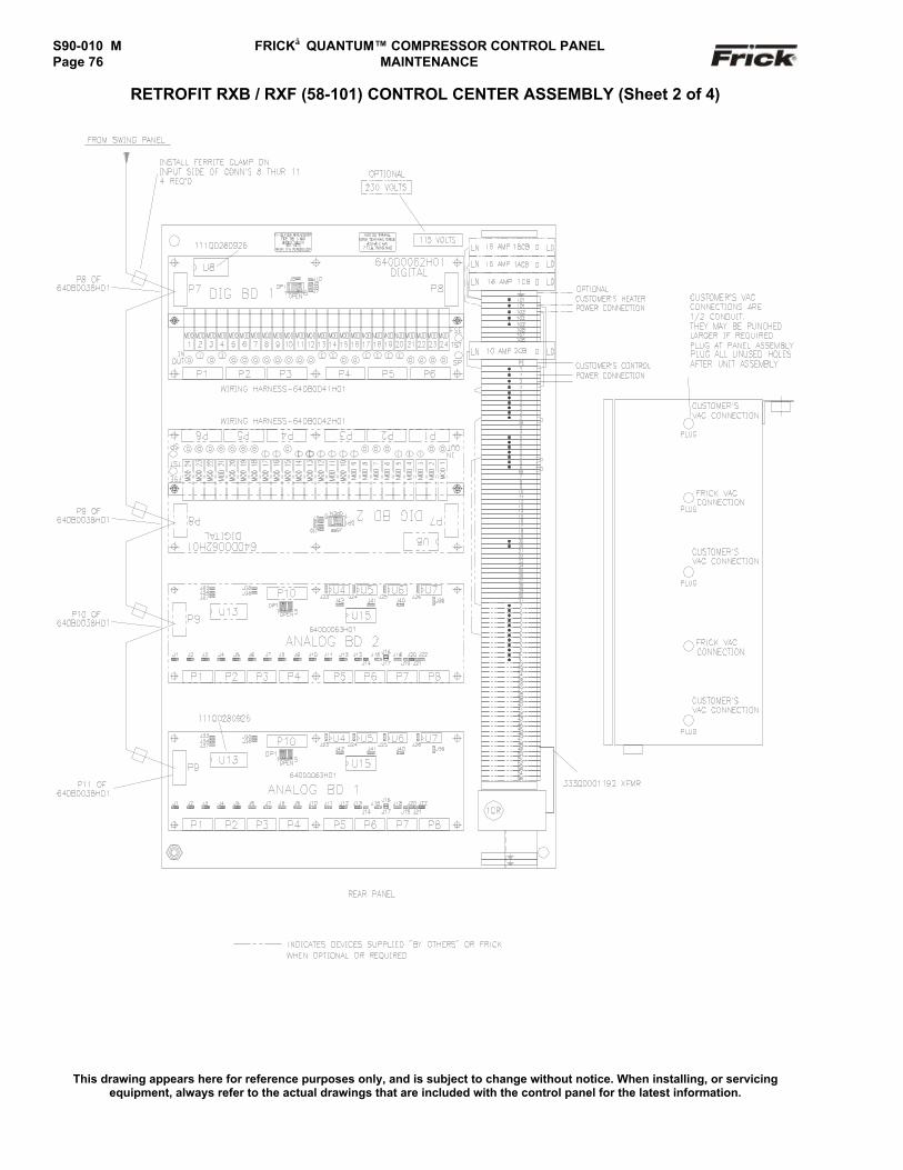
S90-010 M FRICK QUANTUM™ COMPRESSOR CONTROL PANELPage 76 MAINTENANCE
RETROFIT RXB / RXF (58-101) CONTROL CENTER ASSEMBLY (Sheet 2 of 4)
This drawing appears here for reference purposes only, and is subject to change without notice. When installing, or servicingequipment, always refer to the actual drawings that are included with the control panel for the latest information.
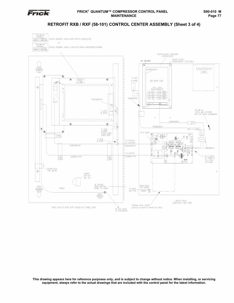
FRICK QUANTUM™ COMPRESSOR CONTROL PANEL S90-010 M MAINTENANCE Page 77
RETROFIT RXB / RXF (58-101) CONTROL CENTER ASSEMBLY (Sheet 3 of 4)
This drawing appears here for reference purposes only, and is subject to change without notice. When installing, or servicingequipment, always refer to the actual drawings that are included with the control panel for the latest information.

S90-010 M FRICK QUANTUM™ COMPRESSOR CONTROL PANELPage 78 MAINTENANCE
RETROFIT RXB / RXF (58-101) CONTROL CENTER ASSEMBLY (Sheet 4 of 4)
This drawing appears here for reference purposes only, and is subject to change without notice. When installing, or servicingequipment, always refer to the actual drawings that are included with the control panel for the latest information.
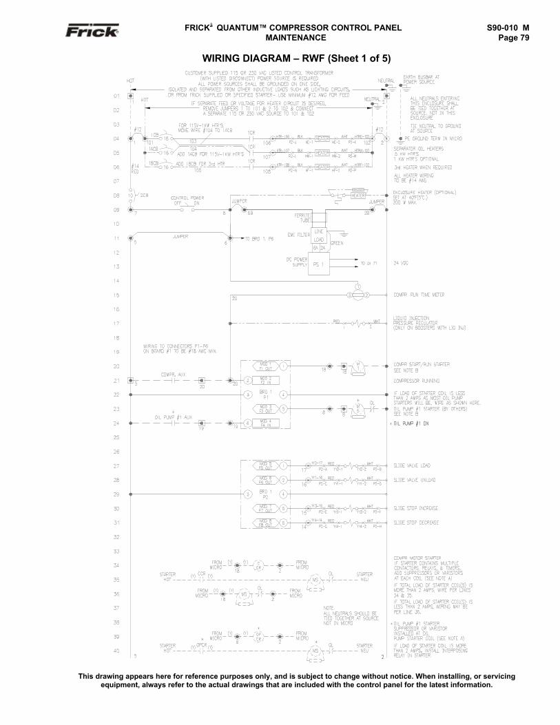
FRICK QUANTUM™ COMPRESSOR CONTROL PANEL S90-010 M MAINTENANCE Page 79
WIRING DIAGRAM – RWF (Sheet 1 of 5)
This drawing appears here for reference purposes only, and is subject to change without notice. When installing, or servicingequipment, always refer to the actual drawings that are included with the control panel for the latest information.
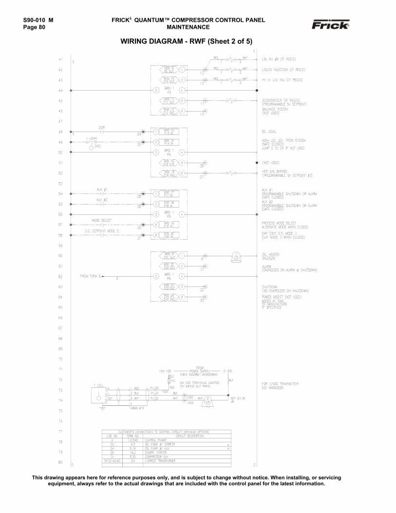
S90-010 M FRICK QUANTUM™ COMPRESSOR CONTROL PANELPage 80 MAINTENANCE
WIRING DIAGRAM - RWF (Sheet 2 of 5)
This drawing appears here for reference purposes only, and is subject to change without notice. When installing, or servicingequipment, always refer to the actual drawings that are included with the control panel for the latest information.
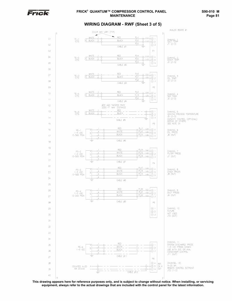
FRICK QUANTUM™ COMPRESSOR CONTROL PANEL S90-010 M MAINTENANCE Page 81
WIRING DIAGRAM - RWF (Sheet 3 of 5)
This drawing appears here for reference purposes only, and is subject to change without notice. When installing, or servicingequipment, always refer to the actual drawings that are included with the control panel for the latest information.
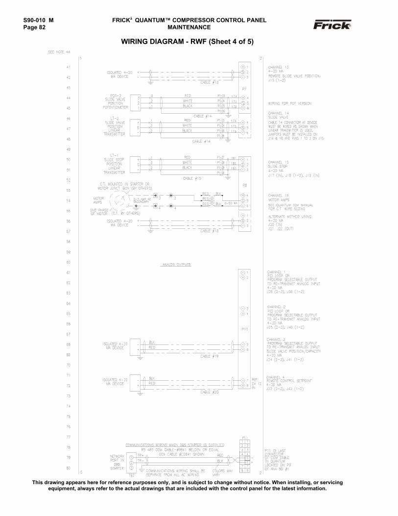
S90-010 M FRICK QUANTUM™ COMPRESSOR CONTROL PANELPage 82 MAINTENANCE
WIRING DIAGRAM - RWF (Sheet 4 of 5)
This drawing appears here for reference purposes only, and is subject to change without notice. When installing, or servicingequipment, always refer to the actual drawings that are included with the control panel for the latest information.
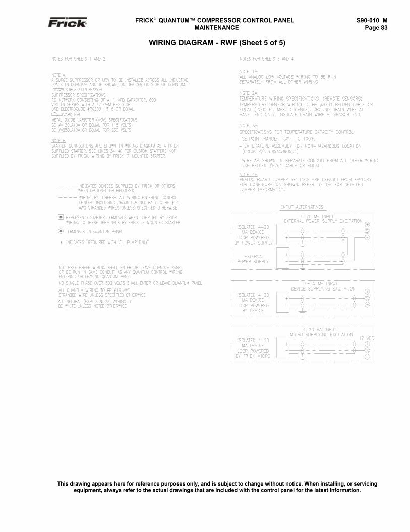
FRICK QUANTUM™ COMPRESSOR CONTROL PANEL S90-010 M MAINTENANCE Page 83
WIRING DIAGRAM - RWF (Sheet 5 of 5)
This drawing appears here for reference purposes only, and is subject to change without notice. When installing, or servicingequipment, always refer to the actual drawings that are included with the control panel for the latest information.
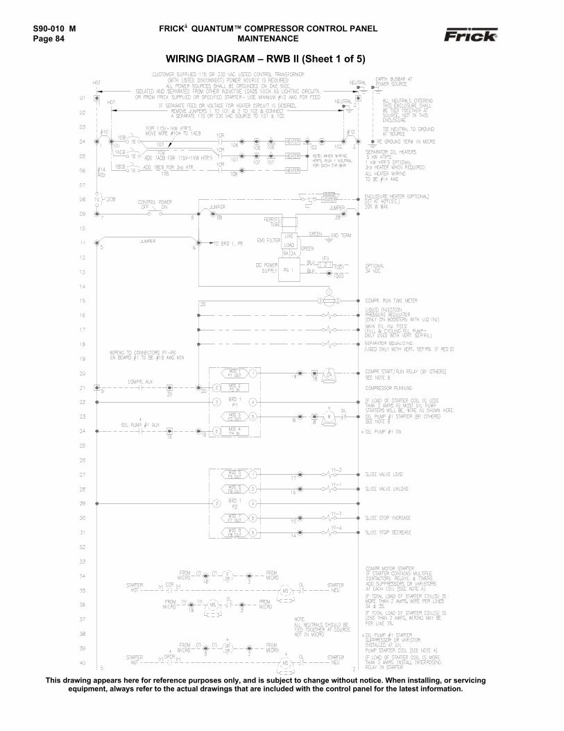
S90-010 M FRICK QUANTUM™ COMPRESSOR CONTROL PANELPage 84 MAINTENANCE
WIRING DIAGRAM – RWB II (Sheet 1 of 5)
This drawing appears here for reference purposes only, and is subject to change without notice. When installing, or servicingequipment, always refer to the actual drawings that are included with the control panel for the latest information.
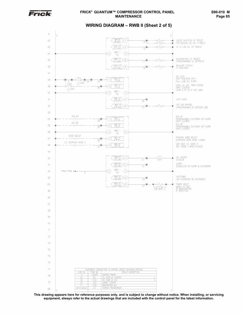
FRICK QUANTUM™ COMPRESSOR CONTROL PANEL S90-010 M MAINTENANCE Page 85
WIRING DIAGRAM – RWB II (Sheet 2 of 5)
This drawing appears here for reference purposes only, and is subject to change without notice. When installing, or servicingequipment, always refer to the actual drawings that are included with the control panel for the latest information.
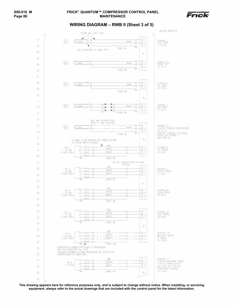
S90-010 M FRICK QUANTUM™ COMPRESSOR CONTROL PANELPage 86 MAINTENANCE
WIRING DIAGRAM – RWB II (Sheet 3 of 5)
This drawing appears here for reference purposes only, and is subject to change without notice. When installing, or servicingequipment, always refer to the actual drawings that are included with the control panel for the latest information.
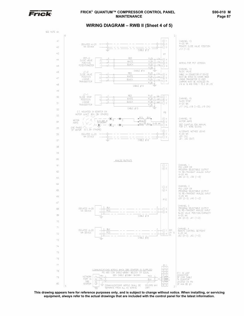
FRICK QUANTUM™ COMPRESSOR CONTROL PANEL S90-010 M MAINTENANCE Page 87
WIRING DIAGRAM – RWB II (Sheet 4 of 5)
This drawing appears here for reference purposes only, and is subject to change without notice. When installing, or servicingequipment, always refer to the actual drawings that are included with the control panel for the latest information.
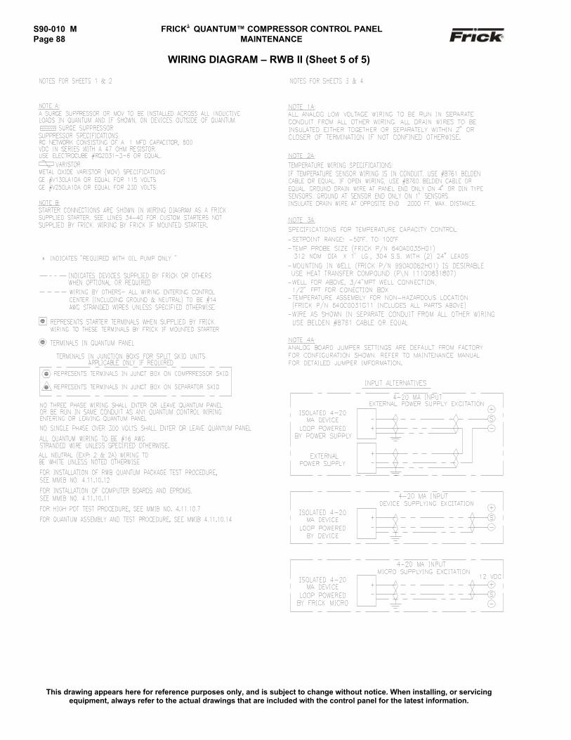
S90-010 M FRICK QUANTUM™ COMPRESSOR CONTROL PANELPage 88 MAINTENANCE
WIRING DIAGRAM – RWB II (Sheet 5 of 5)
This drawing appears here for reference purposes only, and is subject to change without notice. When installing, or servicingequipment, always refer to the actual drawings that are included with the control panel for the latest information.
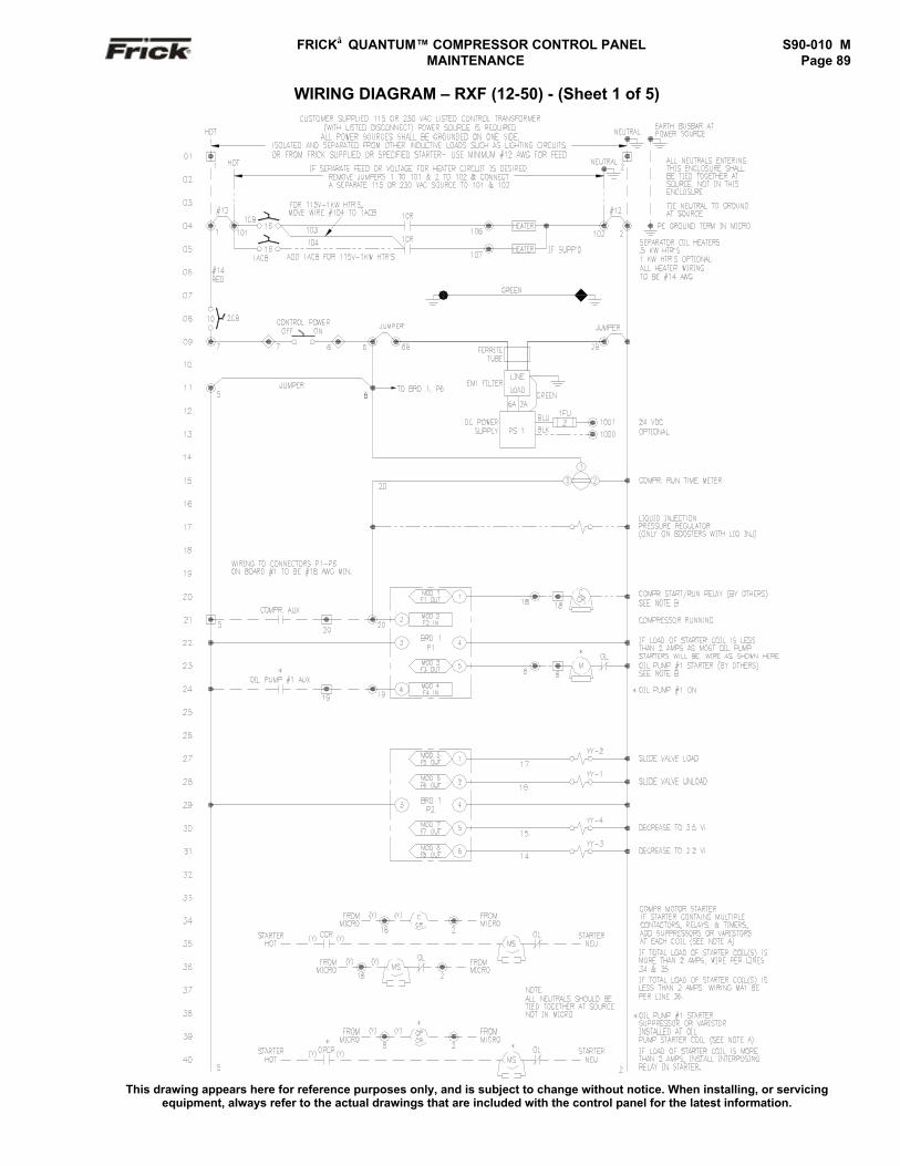
FRICK QUANTUM™ COMPRESSOR CONTROL PANEL S90-010 M MAINTENANCE Page 89
WIRING DIAGRAM – RXF (12-50) - (Sheet 1 of 5)
This drawing appears here for reference purposes only, and is subject to change without notice. When installing, or servicingequipment, always refer to the actual drawings that are included with the control panel for the latest information.
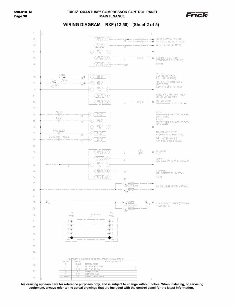
S90-010 M FRICK QUANTUM™ COMPRESSOR CONTROL PANELPage 90 MAINTENANCE
WIRING DIAGRAM – RXF (12-50) - (Sheet 2 of 5)
This drawing appears here for reference purposes only, and is subject to change without notice. When installing, or servicingequipment, always refer to the actual drawings that are included with the control panel for the latest information.
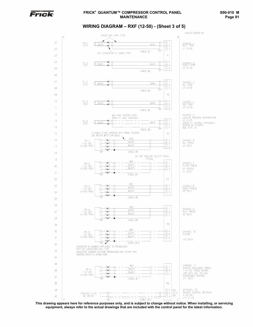
FRICK QUANTUM™ COMPRESSOR CONTROL PANEL S90-010 M MAINTENANCE Page 91
WIRING DIAGRAM – RXF (12-50) - (Sheet 3 of 5)
This drawing appears here for reference purposes only, and is subject to change without notice. When installing, or servicingequipment, always refer to the actual drawings that are included with the control panel for the latest information.
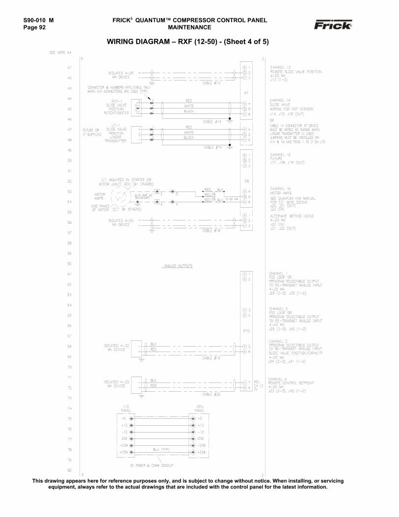
S90-010 M FRICK QUANTUM™ COMPRESSOR CONTROL PANELPage 92 MAINTENANCE
WIRING DIAGRAM – RXF (12-50) - (Sheet 4 of 5)
This drawing appears here for reference purposes only, and is subject to change without notice. When installing, or servicingequipment, always refer to the actual drawings that are included with the control panel for the latest information.
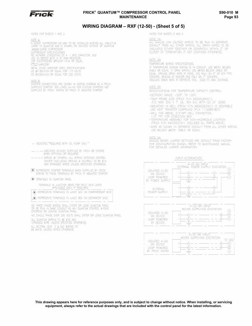
FRICK QUANTUM™ COMPRESSOR CONTROL PANEL S90-010 M MAINTENANCE Page 93
WIRING DIAGRAM – RXF (12-50) - (Sheet 5 of 5)
This drawing appears here for reference purposes only, and is subject to change without notice. When installing, or servicingequipment, always refer to the actual drawings that are included with the control panel for the latest information.
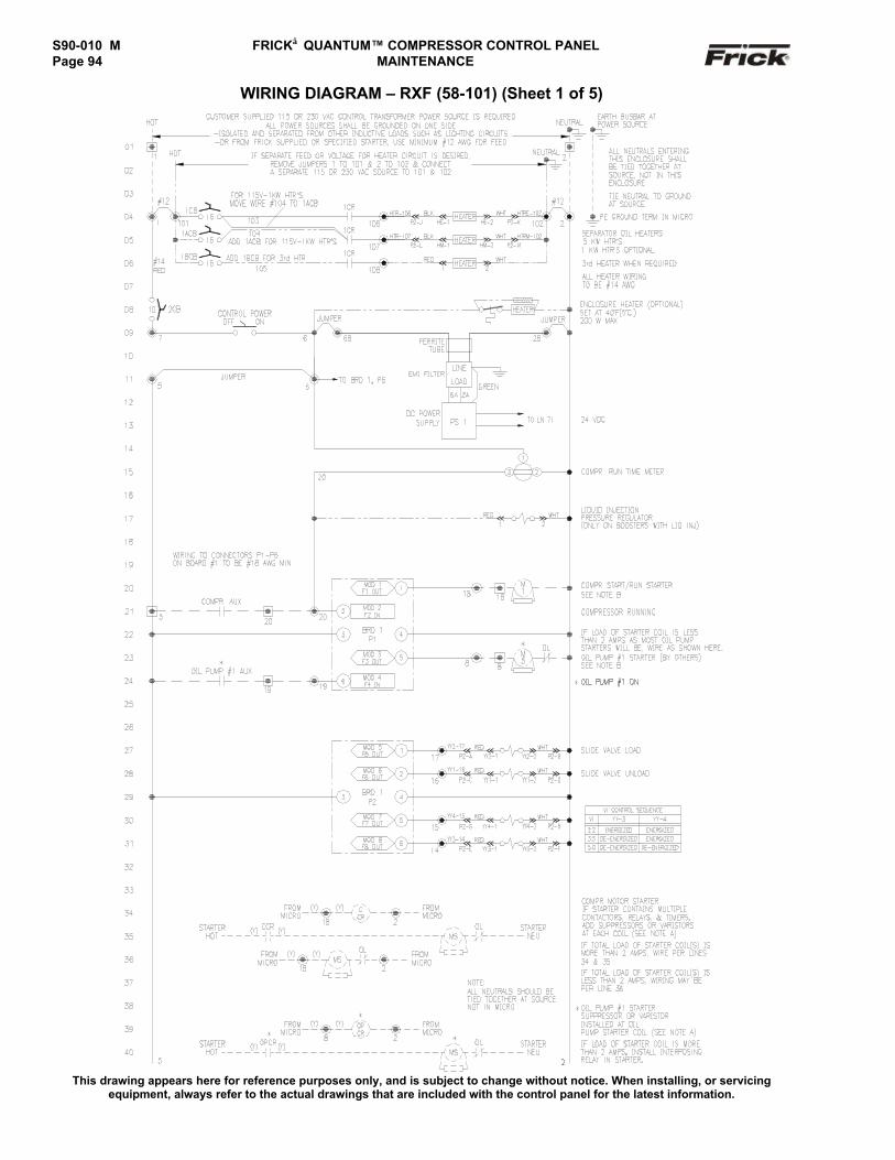
S90-010 M FRICK QUANTUM™ COMPRESSOR CONTROL PANELPage 94 MAINTENANCE
WIRING DIAGRAM – RXF (58-101) (Sheet 1 of 5)
This drawing appears here for reference purposes only, and is subject to change without notice. When installing, or servicingequipment, always refer to the actual drawings that are included with the control panel for the latest information.
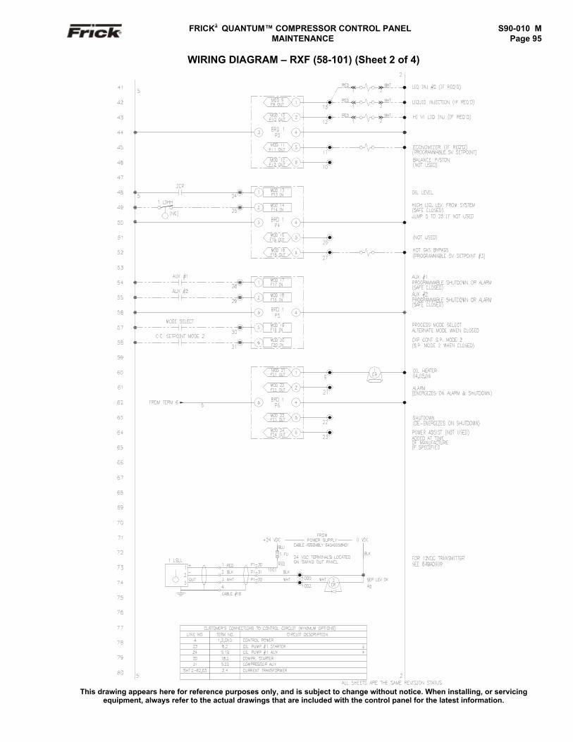
FRICK QUANTUM™ COMPRESSOR CONTROL PANEL S90-010 M MAINTENANCE Page 95
WIRING DIAGRAM – RXF (58-101) (Sheet 2 of 4)
This drawing appears here for reference purposes only, and is subject to change without notice. When installing, or servicingequipment, always refer to the actual drawings that are included with the control panel for the latest information.
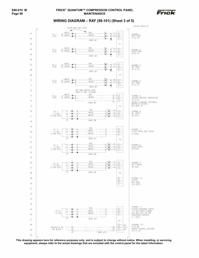
S90-010 M FRICK QUANTUM™ COMPRESSOR CONTROL PANELPage 96 MAINTENANCE
WIRING DIAGRAM – RXF (58-101) (Sheet 3 of 5)
This drawing appears here for reference purposes only, and is subject to change without notice. When installing, or servicingequipment, always refer to the actual drawings that are included with the control panel for the latest information.
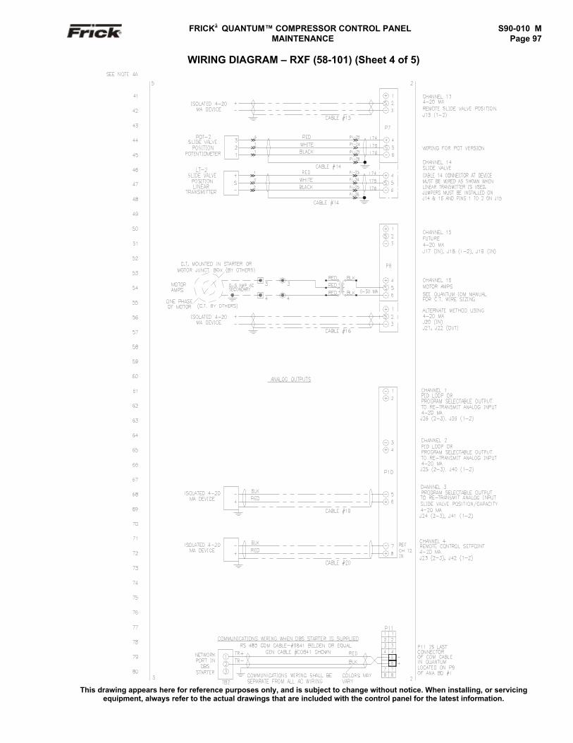
FRICK QUANTUM™ COMPRESSOR CONTROL PANEL S90-010 M MAINTENANCE Page 97
WIRING DIAGRAM – RXF (58-101) (Sheet 4 of 5)
This drawing appears here for reference purposes only, and is subject to change without notice. When installing, or servicingequipment, always refer to the actual drawings that are included with the control panel for the latest information.
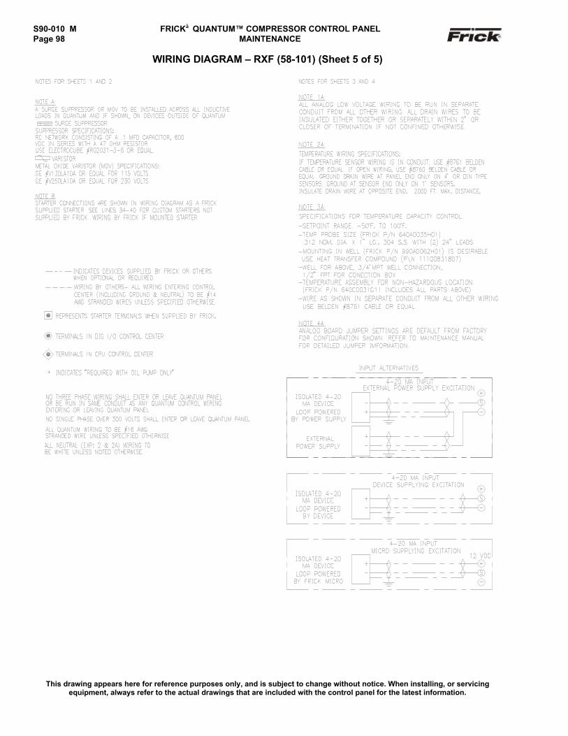
S90-010 M FRICK QUANTUM™ COMPRESSOR CONTROL PANELPage 98 MAINTENANCE
WIRING DIAGRAM – RXF (58-101) (Sheet 5 of 5)
This drawing appears here for reference purposes only, and is subject to change without notice. When installing, or servicingequipment, always refer to the actual drawings that are included with the control panel for the latest information.
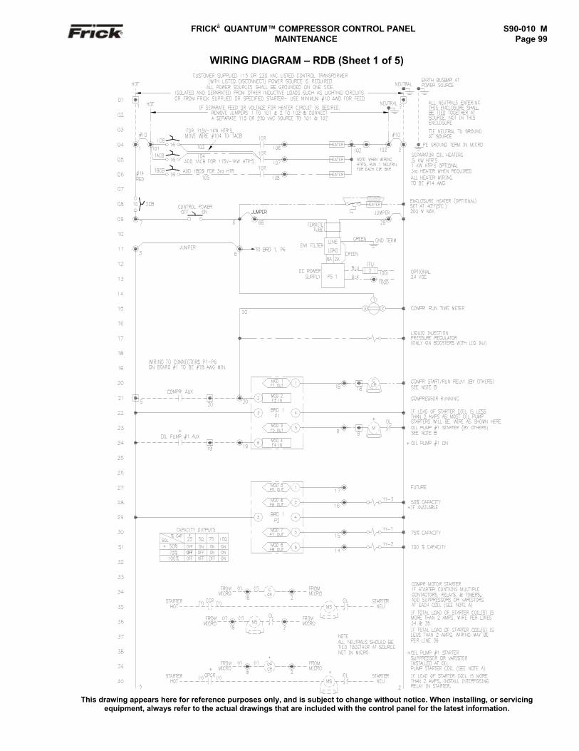
FRICK QUANTUM™ COMPRESSOR CONTROL PANEL S90-010 M MAINTENANCE Page 99
WIRING DIAGRAM – RDB (Sheet 1 of 5)
This drawing appears here for reference purposes only, and is subject to change without notice. When installing, or servicingequipment, always refer to the actual drawings that are included with the control panel for the latest information.
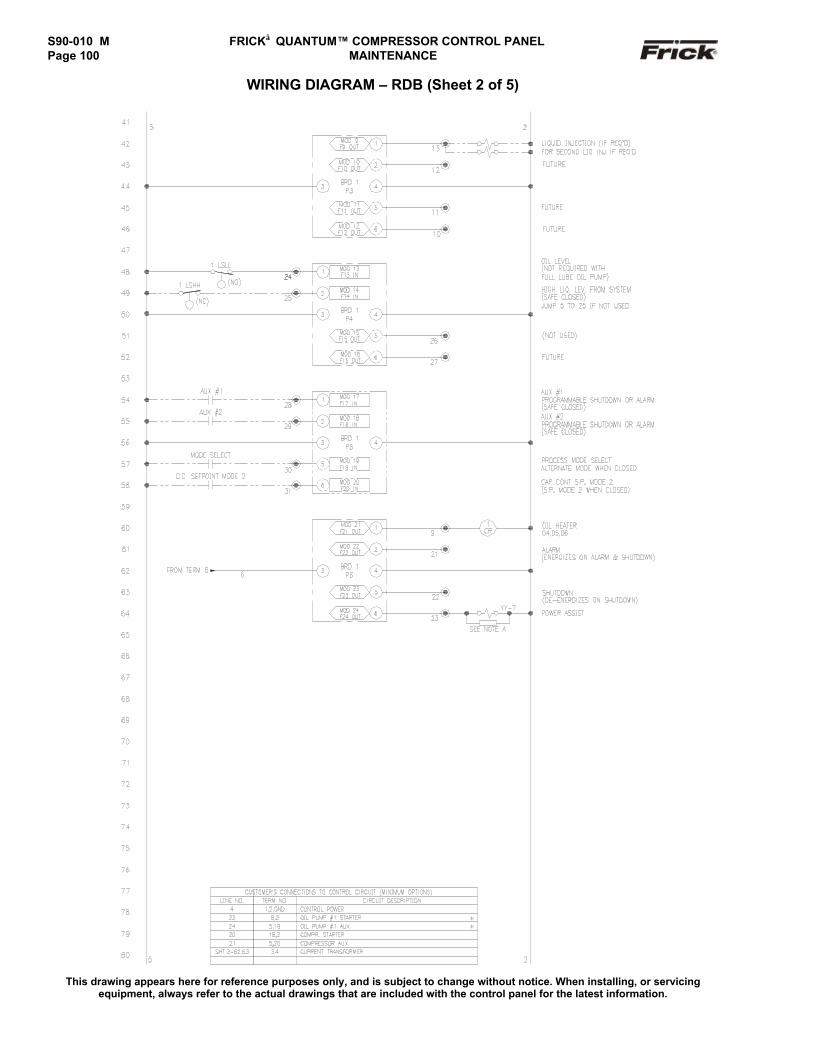
S90-010 M FRICK QUANTUM™ COMPRESSOR CONTROL PANELPage 100 MAINTENANCE
WIRING DIAGRAM – RDB (Sheet 2 of 5)
This drawing appears here for reference purposes only, and is subject to change without notice. When installing, or servicingequipment, always refer to the actual drawings that are included with the control panel for the latest information.
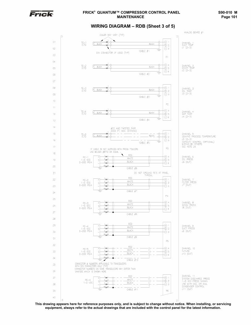
FRICK QUANTUM™ COMPRESSOR CONTROL PANEL S90-010 M MAINTENANCE Page 101
WIRING DIAGRAM – RDB (Sheet 3 of 5)
This drawing appears here for reference purposes only, and is subject to change without notice. When installing, or servicingequipment, always refer to the actual drawings that are included with the control panel for the latest information.
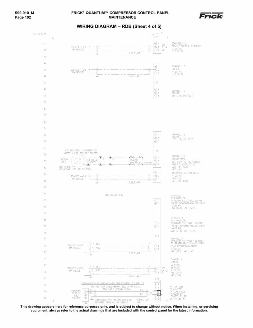
S90-010 M FRICK QUANTUM™ COMPRESSOR CONTROL PANELPage 102 MAINTENANCE
WIRING DIAGRAM – RDB (Sheet 4 of 5)
This drawing appears here for reference purposes only, and is subject to change without notice. When installing, or servicingequipment, always refer to the actual drawings that are included with the control panel for the latest information.
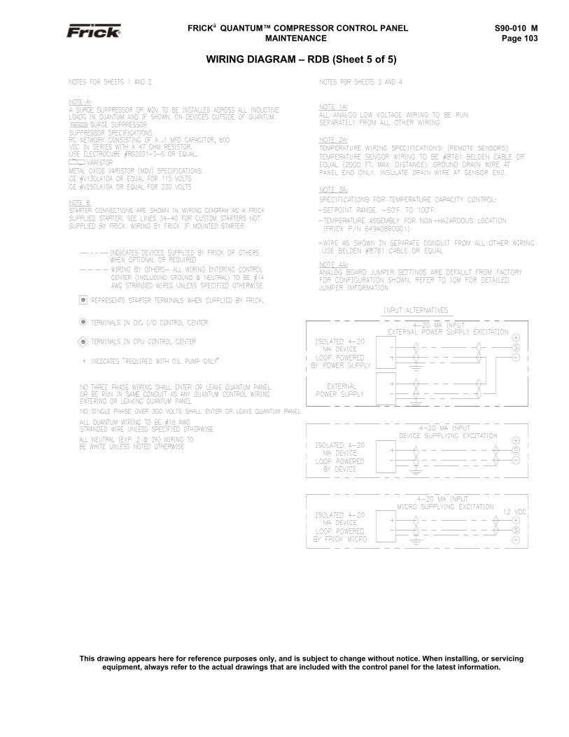
FRICK QUANTUM™ COMPRESSOR CONTROL PANEL S90-010 M MAINTENANCE Page 103
WIRING DIAGRAM – RDB (Sheet 5 of 5)
This drawing appears here for reference purposes only, and is subject to change without notice. When installing, or servicingequipment, always refer to the actual drawings that are included with the control panel for the latest information.
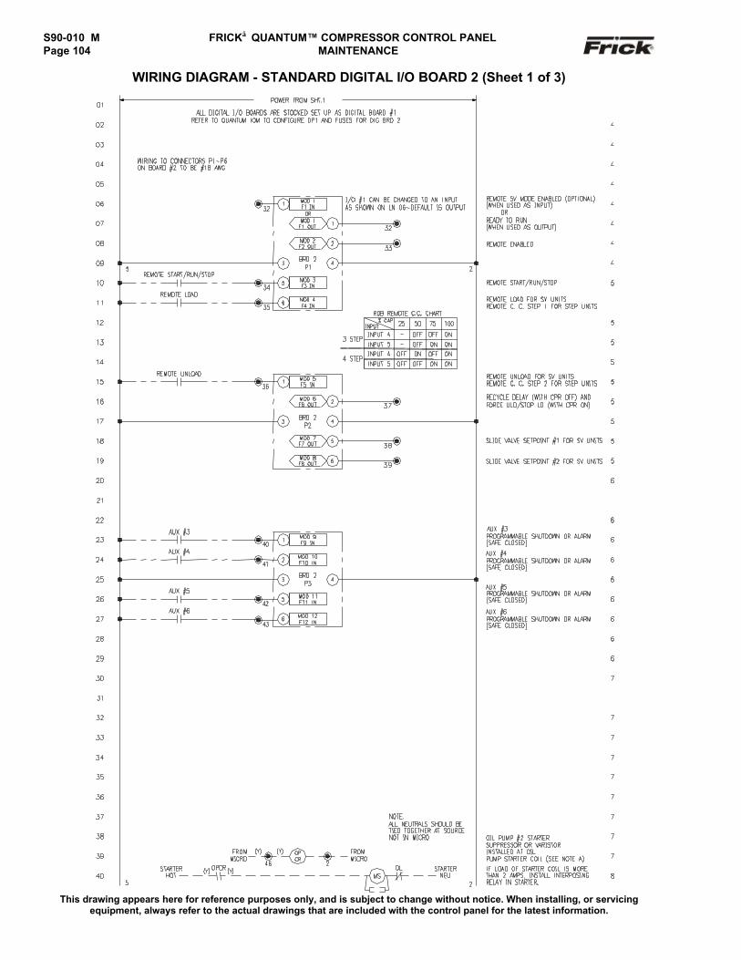
S90-010 M FRICK QUANTUM™ COMPRESSOR CONTROL PANELPage 104 MAINTENANCE
WIRING DIAGRAM - STANDARD DIGITAL I/O BOARD 2 (Sheet 1 of 3)
This drawing appears here for reference purposes only, and is subject to change without notice. When installing, or servicingequipment, always refer to the actual drawings that are included with the control panel for the latest information.
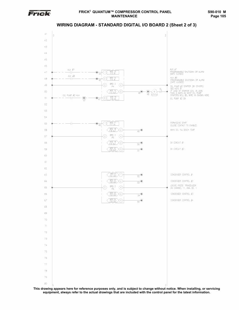
FRICK QUANTUM™ COMPRESSOR CONTROL PANEL S90-010 M MAINTENANCE Page 105
WIRING DIAGRAM - STANDARD DIGITAL I/O BOARD 2 (Sheet 2 of 3)
This drawing appears here for reference purposes only, and is subject to change without notice. When installing, or servicingequipment, always refer to the actual drawings that are included with the control panel for the latest information.
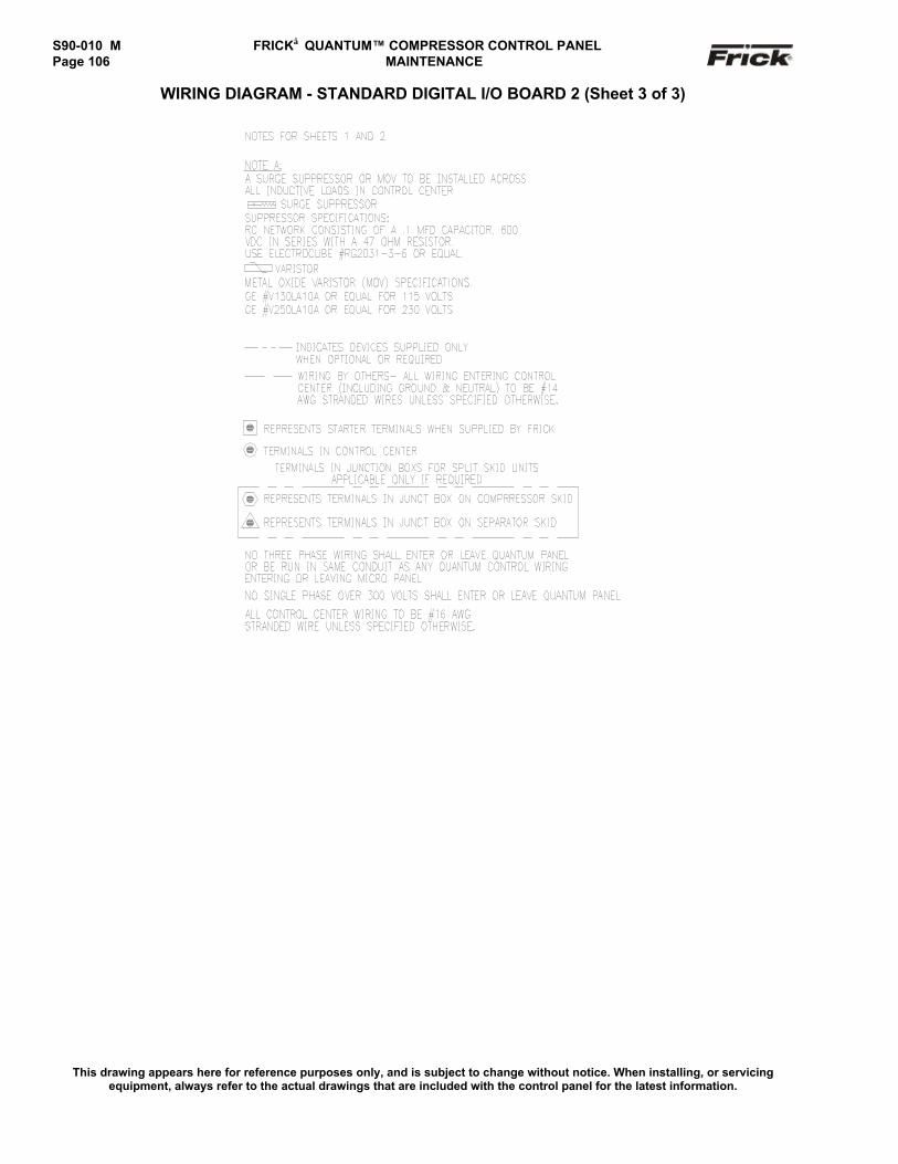
S90-010 M FRICK QUANTUM™ COMPRESSOR CONTROL PANELPage 106 MAINTENANCE
WIRING DIAGRAM - STANDARD DIGITAL I/O BOARD 2 (Sheet 3 of 3)
This drawing appears here for reference purposes only, and is subject to change without notice. When installing, or servicingequipment, always refer to the actual drawings that are included with the control panel for the latest information.
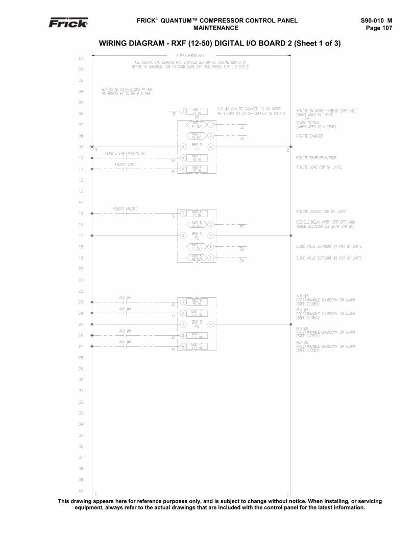
FRICK QUANTUM™ COMPRESSOR CONTROL PANEL S90-010 M MAINTENANCE Page 107
WIRING DIAGRAM - RXF (12-50) DIGITAL I/O BOARD 2 (Sheet 1 of 3)
This drawing appears here for reference purposes only, and is subject to change without notice. When installing, or servicingequipment, always refer to the actual drawings that are included with the control panel for the latest information.
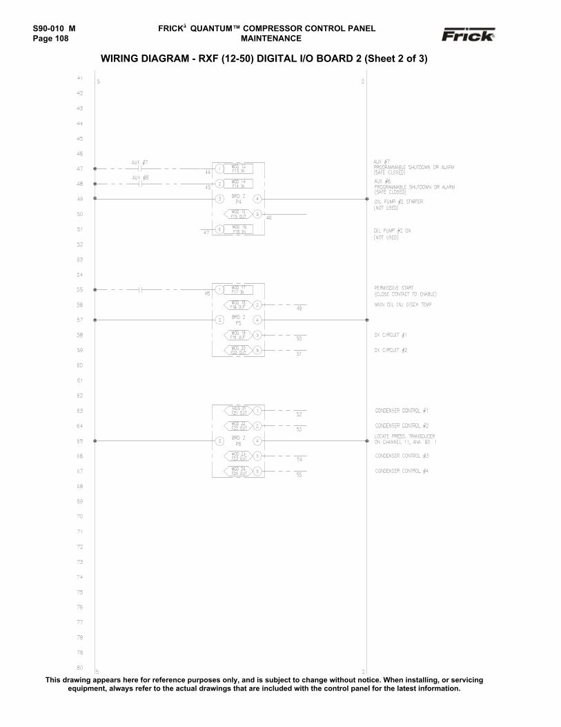
S90-010 M FRICK QUANTUM™ COMPRESSOR CONTROL PANELPage 108 MAINTENANCE
WIRING DIAGRAM - RXF (12-50) DIGITAL I/O BOARD 2 (Sheet 2 of 3)
This drawing appears here for reference purposes only, and is subject to change without notice. When installing, or servicingequipment, always refer to the actual drawings that are included with the control panel for the latest information.
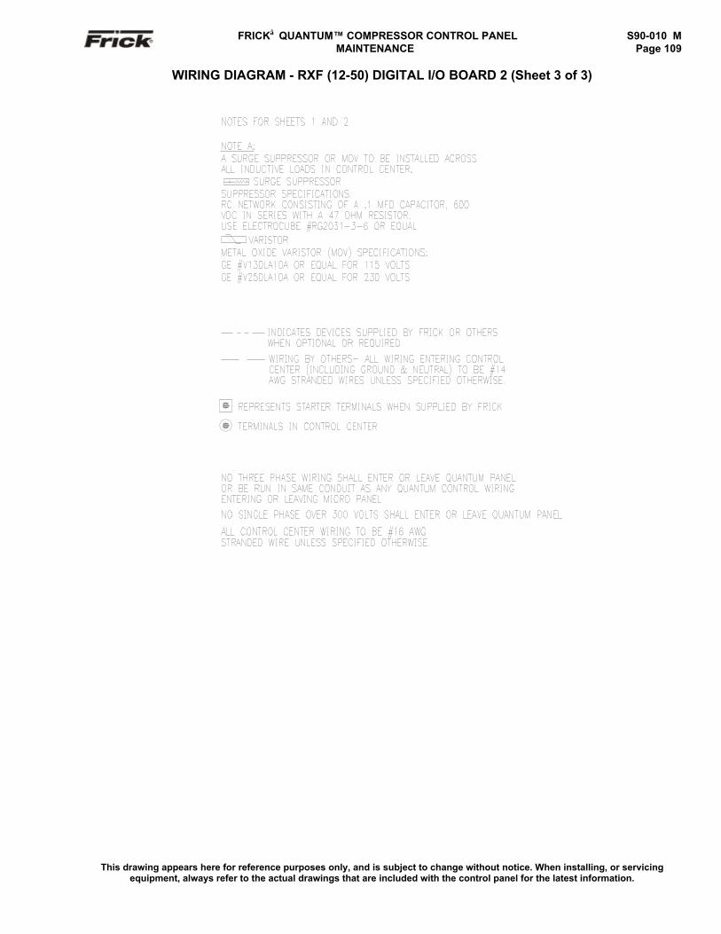
FRICK QUANTUM™ COMPRESSOR CONTROL PANEL S90-010 M MAINTENANCE Page 109
WIRING DIAGRAM - RXF (12-50) DIGITAL I/O BOARD 2 (Sheet 3 of 3)
This drawing appears here for reference purposes only, and is subject to change without notice. When installing, or servicingequipment, always refer to the actual drawings that are included with the control panel for the latest information.
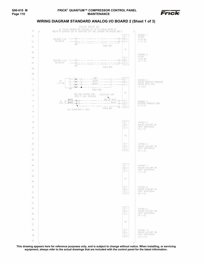
S90-010 M FRICK QUANTUM™ COMPRESSOR CONTROL PANELPage 110 MAINTENANCE
WIRING DIAGRAM STANDARD ANALOG I/O BOARD 2 (Sheet 1 of 3)
This drawing appears here for reference purposes only, and is subject to change without notice. When installing, or servicingequipment, always refer to the actual drawings that are included with the control panel for the latest information.
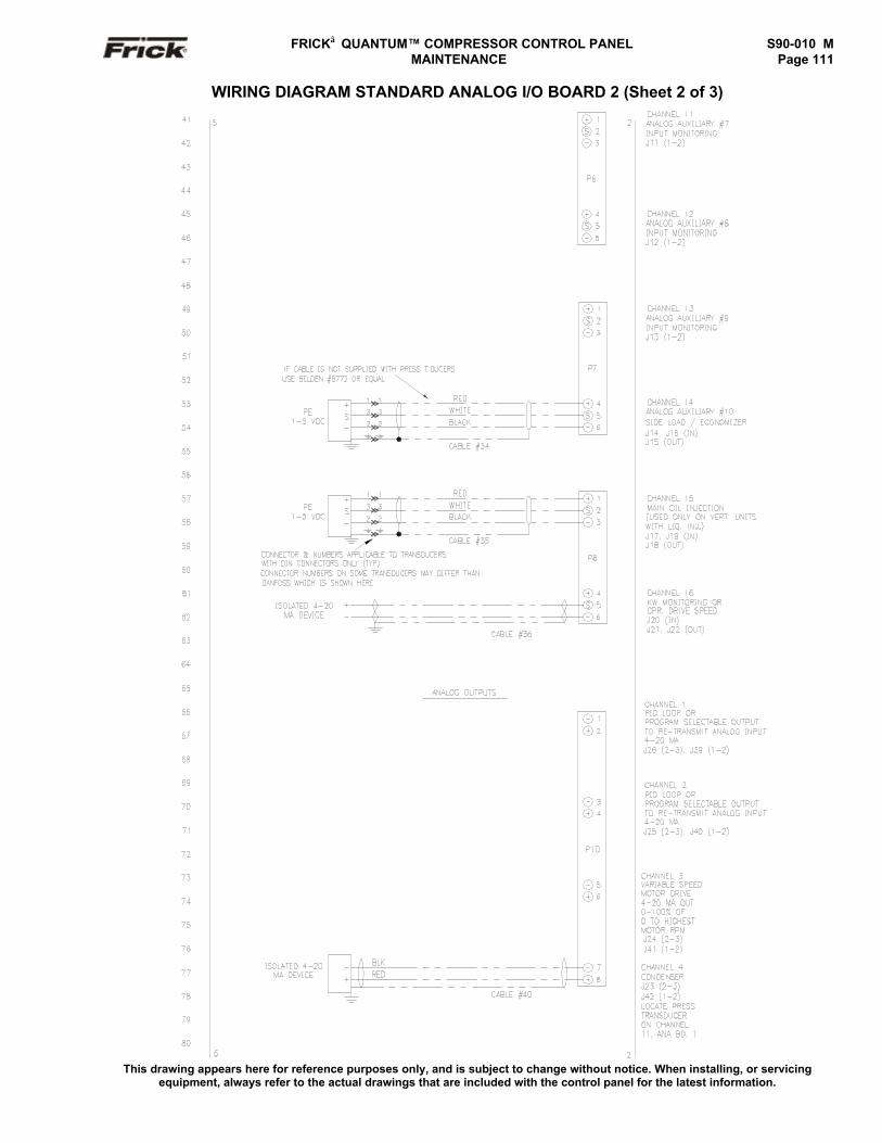
FRICK QUANTUM™ COMPRESSOR CONTROL PANEL S90-010 M MAINTENANCE Page 111
WIRING DIAGRAM STANDARD ANALOG I/O BOARD 2 (Sheet 2 of 3)
This drawing appears here for reference purposes only, and is subject to change without notice. When installing, or servicingequipment, always refer to the actual drawings that are included with the control panel for the latest information.
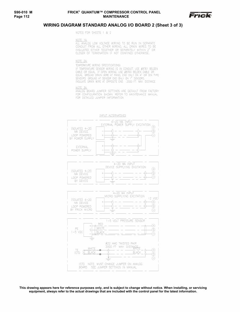
S90-010 M FRICK QUANTUM™ COMPRESSOR CONTROL PANELPage 112 MAINTENANCE
WIRING DIAGRAM STANDARD ANALOG I/O BOARD 2 (Sheet 3 of 3)
This drawing appears here for reference purposes only, and is subject to change without notice. When installing, or servicingequipment, always refer to the actual drawings that are included with the control panel for the latest information.
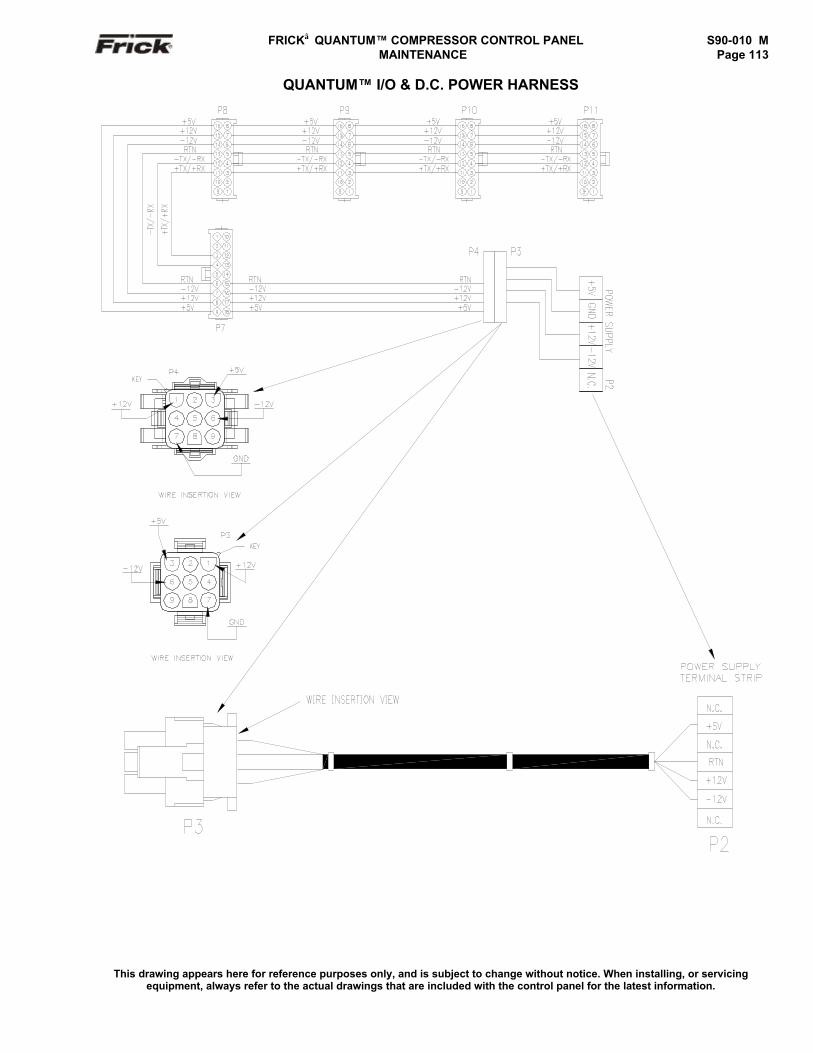
FRICK QUANTUM™ COMPRESSOR CONTROL PANEL S90-010 M MAINTENANCE Page 113
QUANTUM™ I/O & D.C. POWER HARNESS
This drawing appears here for reference purposes only, and is subject to change without notice. When installing, or servicingequipment, always refer to the actual drawings that are included with the control panel for the latest information.
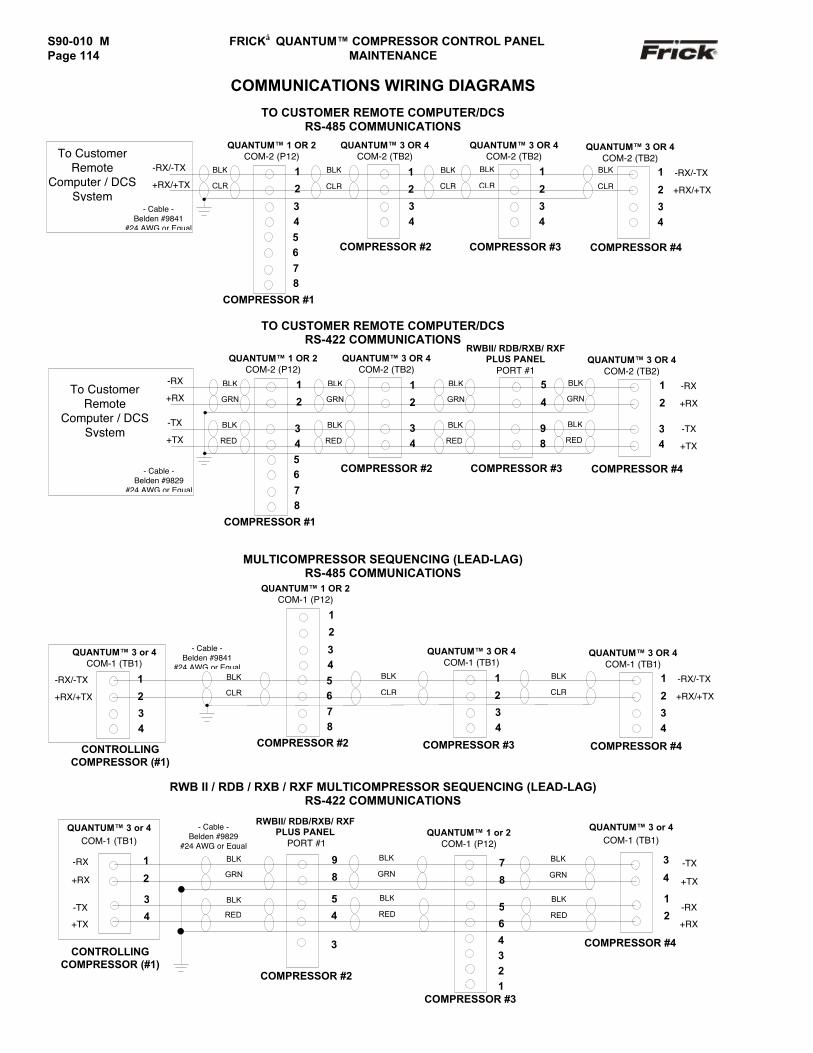
S90-010 M FRICK QUANTUM™ COMPRESSOR CONTROL PANELPage 114 MAINTENANCE
COMMUNICATIONS WIRING DIAGRAMS
TO CUSTOMER REMOTE COMPUTER/DCSRS-485 COMMUNICATIONS
TO CUSTOMER REMOTE COMPUTER/DCSRS-422 COMMUNICATIONS
MULTICOMPRESSOR SEQUENCING (LEAD-LAG)RS-485 COMMUNICATIONS
RWB II / RDB / RXB / RXF MULTICOMPRESSOR SEQUENCING (LEAD-LAG)RS-422 COMMUNICATIONS
7
8
BLK
CLR
COMPRESSOR #4
-RX/-TX
+RX/+TX
- Cable -Belden #9841
#24 AWG or Equal
QUANTUM™ 1 OR 2COM-2 (P12)
COMPRESSOR #1
1
2
34
BLK
CLR
1
2
34
To CustomerRemote
Computer / DCSSystem
-RX/-TX
+RX/+TX
BLK
CLR
COMPRESSOR #2
1
2
34
BLK
CLR
QUANTUM™ 3 OR 4COM-2 (TB2)
QUANTUM™ 3 OR 4COM-2 (TB2)
COMPRESSOR #3
BLK
CLR
1
2
34
QUANTUM™ 3 OR 4COM-2 (TB2)
5678
QUANTUM™ 1 OR 2COM-1 (P12)
COMPRESSOR #2
1
2
345678
-RX/-TX
+RX/+TX
BLK
CLR
- Cable -Belden #9841
#24 AWG or Equal
COMPRESSOR #4
1
2
34
-RX/-TX
+RX/+TX
BLK
CLR
BLK
CLR
COMPRESSOR #3
1
2
34
QUANTUM™ 3 OR 4COM-1 (TB1)
QUANTUM™ 3 OR 4COM-1 (TB1)
CONTROLLINGCOMPRESSOR (#1)
1
2
34
QUANTUM™ 3 or 4COM-1 (TB1)
34
21
3
QUANTUM™ 3 or 4COM-1 (TB1)
-TX
+TX
COMPRESSOR #3
BLK
GRN
BLK
GRN
9
8
QUANTUM™ 1 or 2COM-1 (P12)
RWBII/ RDB/RXB/ RXFPLUS PANEL
PORT #1
CONTROLLINGCOMPRESSOR (#1)
-RX
+RX
1
2
-TX
+TX
3
4
COMPRESSOR #2
BLK
RED5
6
-RX
+RX
BLK
RED
5
4
- Cable -Belden #9829
#24 AWG or Equal
BLK
GRN
BLK
RED
QUANTUM™ 3 or 4COM-1 (TB1)
COMPRESSOR #4
3
4
1
2
5678
-RX
+RX
- Cable -Belden #9829
#24 AWG or Equal
To CustomerRemote
Computer / DCSSystem
QUANTUM™ 3 OR 4COM-2 (TB2)
-TX
+TX-TX
+TX
COMPRESSOR #4
QUANTUM™ 1 OR 2COM-2 (P12)
COMPRESSOR #1
1
2
34
1
2
34
-RX
+RX
COMPRESSOR #2
1
2
34
QUANTUM™ 3 OR 4COM-2 (TB2)
COMPRESSOR #3
5
4
98
RWBII/ RDB/RXB/ RXFPLUS PANEL
PORT #1BLK
GRN
BLK
RED
BLK
GRN
BLK
RED
BLK
GRN
BLK
RED
BLK
GRN
BLK
RED
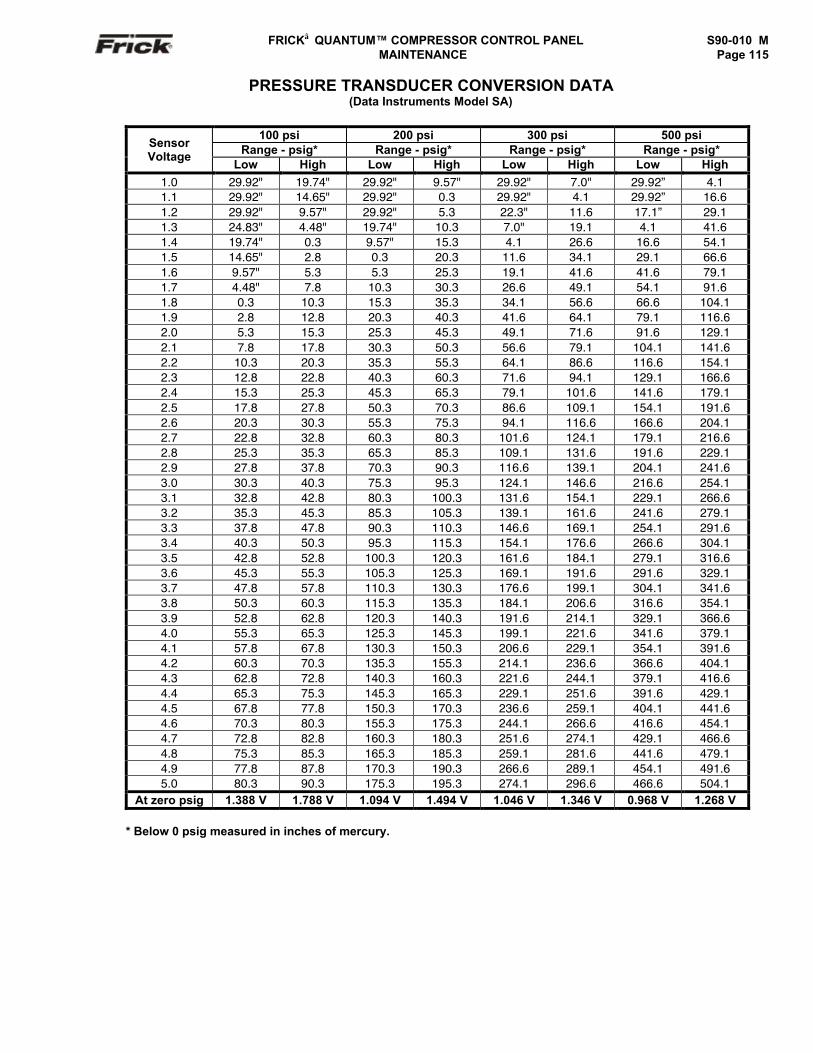
FRICK QUANTUM™ COMPRESSOR CONTROL PANEL S90-010 M MAINTENANCE Page 115
PRESSURE TRANSDUCER CONVERSION DATA(Data Instruments Model SA)
100 psi 200 psi 300 psi 500 psiRange - psig* Range - psig* Range - psig* Range - psig*Sensor
VoltageLow High Low High Low High Low High
1.0 29.92" 19.74" 29.92" 9.57" 29.92" 7.0" 29.92” 4.11.1 29.92" 14.65" 29.92" 0.3 29.92" 4.1 29.92” 16.61.2 29.92" 9.57" 29.92" 5.3 22.3" 11.6 17.1” 29.11.3 24.83" 4.48" 19.74" 10.3 7.0" 19.1 4.1 41.61.4 19.74" 0.3 9.57" 15.3 4.1 26.6 16.6 54.11.5 14.65" 2.8 0.3 20.3 11.6 34.1 29.1 66.61.6 9.57" 5.3 5.3 25.3 19.1 41.6 41.6 79.11.7 4.48" 7.8 10.3 30.3 26.6 49.1 54.1 91.61.8 0.3 10.3 15.3 35.3 34.1 56.6 66.6 104.11.9 2.8 12.8 20.3 40.3 41.6 64.1 79.1 116.62.0 5.3 15.3 25.3 45.3 49.1 71.6 91.6 129.12.1 7.8 17.8 30.3 50.3 56.6 79.1 104.1 141.62.2 10.3 20.3 35.3 55.3 64.1 86.6 116.6 154.12.3 12.8 22.8 40.3 60.3 71.6 94.1 129.1 166.62.4 15.3 25.3 45.3 65.3 79.1 101.6 141.6 179.12.5 17.8 27.8 50.3 70.3 86.6 109.1 154.1 191.62.6 20.3 30.3 55.3 75.3 94.1 116.6 166.6 204.12.7 22.8 32.8 60.3 80.3 101.6 124.1 179.1 216.62.8 25.3 35.3 65.3 85.3 109.1 131.6 191.6 229.12.9 27.8 37.8 70.3 90.3 116.6 139.1 204.1 241.63.0 30.3 40.3 75.3 95.3 124.1 146.6 216.6 254.13.1 32.8 42.8 80.3 100.3 131.6 154.1 229.1 266.63.2 35.3 45.3 85.3 105.3 139.1 161.6 241.6 279.13.3 37.8 47.8 90.3 110.3 146.6 169.1 254.1 291.63.4 40.3 50.3 95.3 115.3 154.1 176.6 266.6 304.13.5 42.8 52.8 100.3 120.3 161.6 184.1 279.1 316.63.6 45.3 55.3 105.3 125.3 169.1 191.6 291.6 329.13.7 47.8 57.8 110.3 130.3 176.6 199.1 304.1 341.63.8 50.3 60.3 115.3 135.3 184.1 206.6 316.6 354.13.9 52.8 62.8 120.3 140.3 191.6 214.1 329.1 366.64.0 55.3 65.3 125.3 145.3 199.1 221.6 341.6 379.14.1 57.8 67.8 130.3 150.3 206.6 229.1 354.1 391.64.2 60.3 70.3 135.3 155.3 214.1 236.6 366.6 404.14.3 62.8 72.8 140.3 160.3 221.6 244.1 379.1 416.64.4 65.3 75.3 145.3 165.3 229.1 251.6 391.6 429.14.5 67.8 77.8 150.3 170.3 236.6 259.1 404.1 441.64.6 70.3 80.3 155.3 175.3 244.1 266.6 416.6 454.14.7 72.8 82.8 160.3 180.3 251.6 274.1 429.1 466.64.8 75.3 85.3 165.3 185.3 259.1 281.6 441.6 479.14.9 77.8 87.8 170.3 190.3 266.6 289.1 454.1 491.65.0 80.3 90.3 175.3 195.3 274.1 296.6 466.6 504.1
At zero psig 1.388 V 1.788 V 1.094 V 1.494 V 1.046 V 1.346 V 0.968 V 1.268 V
* Below 0 psig measured in inches of mercury.
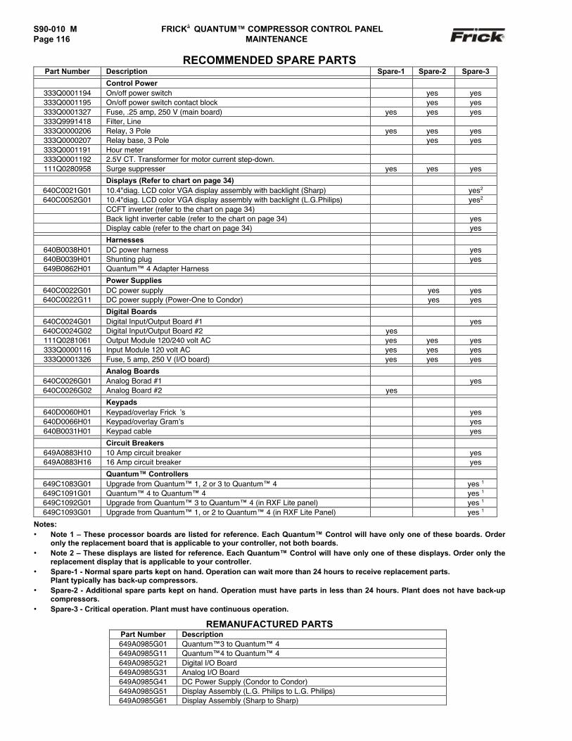
S90-010 M FRICK QUANTUM™ COMPRESSOR CONTROL PANELPage 116 MAINTENANCE
RECOMMENDED SPARE PARTSPart Number Description Spare-1 Spare-2 Spare-3
Control Power333Q0001194 On/off power switch yes yes333Q0001195 On/off power switch contact block yes yes333Q0001327 Fuse, .25 amp, 250 V (main board) yes yes yes333Q9991418 Filter, Line333Q0000206 Relay, 3 Pole yes yes yes333Q0000207 Relay base, 3 Pole yes yes333Q0001191 Hour meter333Q0001192 2.5V CT. Transformer for motor current step-down.111Q0280958 Surge suppresser yes yes yes
Displays (Refer to chart on page 34)640C0021G01 10.4"diag. LCD color VGA display assembly with backlight (Sharp) yes2
640C0052G01 10.4"diag. LCD color VGA display assembly with backlight (L.G.Philips) yes2
CCFT inverter (refer to the chart on page 34)Back light inverter cable (refer to the chart on page 34) yesDisplay cable (refer to the chart on page 34) yes
Harnesses640B0038H01 DC power harness yes640B0039H01 Shunting plug yes649B0862H01 Quantum™ 4 Adapter Harness
Power Supplies640C0022G01 DC power supply yes yes640C0022G11 DC power supply (Power-One to Condor) yes yes
Digital Boards640C0024G01 Digital Input/Output Board #1 yes640C0024G02 Digital Input/Output Board #2 yes111Q0281061 Output Module 120/240 volt AC yes yes yes333Q0000116 Input Module 120 volt AC yes yes yes333Q0001326 Fuse, 5 amp, 250 V (I/O board) yes yes yes
Analog Boards640C0026G01 Analog Borad #1 yes640C0026G02 Analog Board #2 yes
Keypads640D0060H01 Keypad/overlay Frick’s yes640D0066H01 Keypad/overlay Gram’s yes640B0031H01 Keypad cable yes
Circuit Breakers649A0883H10 10 Amp circuit breaker yes649A0883H16 16 Amp circuit breaker yes
Quantum™ Controllers649C1083G01 Upgrade from Quantum™ 1, 2 or 3 to Quantum™ 4 yes 1
649C1091G01 Quantum™ 4 to Quantum™ 4 yes 1
649C1092G01 Upgrade from Quantum™ 3 to Quantum™ 4 (in RXF Lite panel) yes 1
649C1093G01 Upgrade from Quantum™ 1, or 2 to Quantum™ 4 (in RXF Lite Panel) yes 1
Notes:• Note 1 – These processor boards are listed for reference. Each Quantum™ Control will have only one of these boards. Order
only the replacement board that is applicable to your controller, not both boards.• Note 2 – These displays are listed for reference. Each Quantum™ Control will have only one of these displays. Order only the
replacement display that is applicable to your controller.• Spare-1 - Normal spare parts kept on hand. Operation can wait more than 24 hours to receive replacement parts.
Plant typically has back-up compressors.• Spare-2 - Additional spare parts kept on hand. Operation must have parts in less than 24 hours. Plant does not have back-up
compressors.• Spare-3 - Critical operation. Plant must have continuous operation.
REMANUFACTURED PARTSPart Number Description649A0985G01 Quantum™3 to Quantum™ 4649A0985G11 Quantum™4 to Quantum™ 4649A0985G21 Digital I/O Board649A0985G31 Analog I/O Board649A0985G41 DC Power Supply (Condor to Condor)649A0985G51 Display Assembly (L.G. Philips to L.G. Philips)649A0985G61 Display Assembly (Sharp to Sharp)
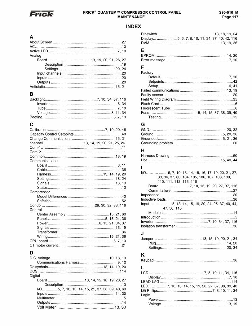
FRICK QUANTUM™ COMPRESSOR CONTROL PANEL S90-010 M MAINTENANCE Page 117
INDEX
AAbout Screen ..................................................................27AC…..…. .........................................................................10Active LED ..................................................................7, 10Analog
Board .........................................13, 19, 20, 21, 26, 27Description........................................................19Settings.......................................................20, 24
Input channels..........................................................20Inputs .......................................................................20Outputs ....................................................................20
Antistatic....................................................................15, 21
BBacklight..................................................7, 10, 34, 37, 116
Inverter.................................................................6, 34Tube.....................................................................7, 10Voltage...........................................................8, 11, 34
Booting... .................................................................6, 7, 10
CCalibration .......................................................7, 10, 20, 46Capacity Control Setpoints..............................................48Change Communications ..........................................15, 21channel …………………………..13, 14, 19, 20, 21, 25, 26Com-1…..........................................................................11Com-2…..........................................................................11Common....................................................................13, 19Communications
Board ...................................................................8, 11Cable........................................................................36Harness..................................................13, 14, 19, 20Settings ..............................................................18, 24Signals ...............................................................13, 19Status.......................................................................13
CompressorModel Differences ....................................................40Safeties ....................................................................52
Condor... ...............................................29, 30, 32, 33, 116Control
Center Assembly..........................................15, 21, 60Panel…. ...................................................5, 15, 21, 36Power.................................................6, 15, 21, 34, 37Signals ...............................................................13, 19Transformer .............................................................36Wiring...........................................................15, 21, 36
CPU board ..............................................................6, 7, 10CT motor current .............................................................21
DD.C. voltage ........................................................10, 13, 19
Communications Harness ....................................9, 12Daisychain.....................................................13, 14, 19, 20DCS..….. .......................................................................114Digital
Board ...................................13, 14, 15, 18, 19, 20, 27Description........................................................13
I/O... ........... 5, 7, 10, 13, 14, 15, 21, 37, 38, 39, 40, 60Inputs .................................................................14, 20Multimeter ..................................................................5Outputs ....................................................................14Volt Meter ...................................................13, 30
Dipswitch.......................................................13, 18, 19, 24Display... ................... 5, 6, 7, 8, 10, 11, 34, 37, 40, 42, 116DVM.….. .............................................................13, 19, 36
EEPROM.. ...................................................................14, 20Error message ............................................................7, 10
FFactory
Default .................................................................7, 10Setpoints..................................................................42Setup ...................................................................6, 41
Failed communications .............................................13, 19Faulty sensor ..................................................................20Field Wiring Diagram.......................................................35Flash Card ........................................................................6Fluorescent Tube ..............................................................6Fuse.….. ....................................... 5, 14, 15, 37, 38, 39, 40
Testing .....................................................................15
GGND.….. ...................................................................20, 32Ground... ...............................................................5, 20, 36Grounded ..............................................................5, 21, 36Grounding problem .........................................................20
HHarness Drawing.............................................................60Hot.……. .............................................................15, 40, 44
II/O………. ........ 5, 7, 10, 13, 14, 15, 16, 17, 19, 20, 21, 27,
30, 36, 37, 60, 104, 105, 106, 107, 108, 109,110, 111, 112, 113, 116
Board ............................. 7, 10, 13, 19, 20, 27, 37, 116Comm failure............................................................27
Impedance ......................................................................20Inductive loads ................................................................36Input……….. ........ 5, 13, 14, 15, 19, 20, 24, 25, 37, 40, 44,
47, 56, 116Modules ...................................................................14
Introduction .......................................................................5Inverter....................................................7, 10, 34, 37, 116Isolation transformer .......................................................36
JJumper… ..........................................13, 15, 19, 20, 21, 34
Plug....................................................................14, 20Settings..............................................................20, 34
KKeypad............................................................................36
LLCD……..............................................7, 8, 10, 11, 34, 116
Display .................................................................7, 10LEAD-LAG ....................................................................114LED.……......... 7, 10, 13, 14, 15, 19, 20, 27, 37, 38, 39, 40LG Philips....................................................7, 8, 10, 11, 34Logic
Power.......................................................................13Voltage...............................................................13, 19
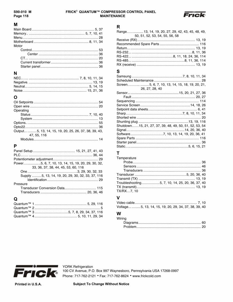
S90-010 M FRICK QUANTUM™ COMPRESSOR CONTROL PANELPage 118 MAINTENANCE
MMain Board ................................................................. 5, 37Memory.. .......................................................... 5, 7, 10, 41Menu.….......................................................................... 28Motherboard ......................................................... 8, 11, 34Motor
Control..................................................................... 53Center .............................................................. 36
CT... ........................................................................ 20Current transformer ................................................. 36Starter panel............................................................ 36
NNEC..….. .................................................... 7, 8, 10, 11, 34Negative. .................................................................. 13, 19Neutral... ............................................................... 5, 14, 15Noise…............................................................... 15, 21, 36
OOil Setpoints ................................................................... 54Open wire ....................................................................... 20Operating
Status ............................................................ 7, 10, 40System .................................................................... 13
Options.. ......................................................................... 55Opto22............................................................................ 36Output… .........5, 13, 14, 15, 19, 20, 25, 26, 37, 38, 39, 43,
47, 55, 116Modules................................................................... 14
PPanel Setup............................................ 15, 21, 27, 41, 43PLC.…… .................................................................. 36, 44Potentiometer adjustment............................................... 29Power…..............5, 6, 7, 10, 13, 14, 15, 19, 20, 29, 30, 32,
33, 36, 37, 38, 44, 45, 53, 60, 116One……………………………………..3, 29, 30, 32, 33Supply ..........5, 13, 14, 19, 20, 29, 30, 32, 33, 37, 116
Identification ..................................................... 29Pressure
Transducer Conversion Data................................. 115Transducers ................................................ 20, 36, 46
QQuantum™ 1 ...................................................... 5, 29, 116Quantum™ 2 .................................................................... 5Quantum™ 3 ...................................5, 7, 8, 29, 34, 37, 116Quantum™ 4 ............................................ 5, 10, 11, 29, 34
RRange……..........13, 14, 19, 20, 27, 29, 42, 43, 45, 48, 49, 50, 51, 52, 53, 54, 55, 56, 58Receive (RX) ............................................................ 13, 19Recommended Spare Parts ......................................... 116Return…................................................................... 13, 19RS-232... ...............................................................8, 11, 36RS-422... ...........................................8, 11, 18, 24, 36, 114RS-485... .......................................................8, 11, 36, 114RX (receive) ............................................................. 13, 19
SSamsung .....................................................7, 8, 10, 11, 34Scheduled Maintenance................................................. 28Screen……….. .........5, 6, 7, 10, 13, 14, 15, 18, 19, 20, 21,
26, 27, 28, 40Sensor... ..................................................15, 20, 21, 27, 36
Fault .................................................................. 20, 27Sequencing .................................................................. 114Service Screen....................................................14, 18, 26Setpoint data sheets................................................... 6, 41Sharp…………………………………………..7, 8, 10, 11, 34Shorted wire ................................................................... 20Shunting plug ....................................................13, 19, 116Shutdown……15, 21, 27, 37, 39, 48, 49, 50, 51, 52, 53, 54Signal.…........................................................14, 20, 36, 40Software………………………..7, 10, 13, 14, 19, 20, 36, 41Spare Parts .................................................................. 116Starter panel................................................................... 36Static…..............................................................5, 6, 15, 21
TTemperature
Probe....................................................................... 36Sensors ................................................................... 46Transducers ............................................................ 36
Transducer ......................................................5, 20, 36, 40Transmit (TX) ........................................................... 13, 19Troubleshooting...................5, 7, 10, 14, 25, 20, 36, 37, 40TX (transmit)............................................................. 13, 19TX/RX…7, 10
VVideo cable................................................................. 7, 10Voltage... .........5, 13, 14, 15, 19, 20, 29, 34, 37, 38, 39, 40
WWiring
Diagrams................................................................. 60Problem................................................................... 20
YORK Refrigeration100 CV Avenue, P.O. Box 997 Waynesboro, Pennsylvania USA 17268-0997Phone: 717-762-2121 • Fax: 717-762-8624 • www.frickcold.com
Subject To Change Without NoticePrinted in U.S.A.