FRESNO UNIFIED SCHOOL DISTRICT SCOPE OF … Opportunities1... · SCOPE OF WORK SECTION 01100 Fresno...
59
SCOPE OF WORK SECTION 01100 Fresno Unified School District; Prepared 6/6/2017 Informal Bid 1475-26008, Wawona M.S. Playground Equipment Installation Scope of Work Page 1 of 2 FRESNO UNIFIED SCHOOL DISTRICT SCOPE OF WORK AND TECHNICAL SPECIFICATIONS QUALIFICATIONS 1. Playground structure installation contractor must be National Playground Safety Institute (NPSI) certified and/or supply a certification by a NPSI Certified Inspector after installation, shall be certified by the playground equipment manufacturer, and shall install the equipment to the manufacturer’s installation instructions and specifications. 2. Playground safety surfacing tile installation contractor must employ a factory trained and certified installer that is approved by manufacturer. 3. Related Sections: a. 02831 – Chain Link Fence and Gates b. 03200 – Steel Reinforcement c. 03300 – Cast-In-Place Concrete SCOPE OF WORK 1. Contractor is responsible for providing temporary restroom, wash basin and fencing (non- barbed) to secure entire job site and staging area. 2. Contractor shall be responsible for demolition and off-haul of existing concrete, earthwork, trees and roots per plans and specifications. 3. Contractor shall be responsible for installation of owner-provided play equipment and associated concrete footings, play area concrete border, steel reinforcement, rebar doweling, miscellaneous concrete flatwork, installation of owner-provided safety tile playground surfacing, and new chain-link fencing and gates. 4. Contractor shall compact subgrade below play area concrete slab and curb border to 90% relative compaction. 5. Contractor is responsible for installing owner-provided play structure material per design shown in Miracle Play Systems drawing #17_0602_Wawona-004 dated 6/1/2017. 6. Contractor is responsible for backfilling and finish grading any areas of rutting that occur during construction, finish grading surrounding new concrete curbing, sidewalks, and mow strips. Finish grading to be free from rutting and prepped for district reseeding operations. 7. Footprint of playground and fence dimensions are to be confirmed by contractor prior to bid. Contractor’s proposal shall be inclusive of actual dimensions.
Transcript of FRESNO UNIFIED SCHOOL DISTRICT SCOPE OF … Opportunities1... · SCOPE OF WORK SECTION 01100 Fresno...

SCOPE OF WORK
SECTION 01100
Fresno Unified School District; Prepared 6/6/2017 Informal Bid 1475-26008, Wawona M.S. Playground Equipment Installation
Scope of Work Page 1 of 2
FRESNO UNIFIED SCHOOL DISTRICT SCOPE OF WORK AND TECHNICAL SPECIFICATIONS
QUALIFICATIONS
1. Playground structure installation contractor must be National Playground Safety Institute
(NPSI) certified and/or supply a certification by a NPSI Certified Inspector after
installation, shall be certified by the playground equipment manufacturer, and shall install
the equipment to the manufacturer’s installation instructions and specifications.
2. Playground safety surfacing tile installation contractor must employ a factory trained and
certified installer that is approved by manufacturer.
3. Related Sections:
a. 02831 – Chain Link Fence and Gates
b. 03200 – Steel Reinforcement
c. 03300 – Cast-In-Place Concrete
SCOPE OF WORK
1. Contractor is responsible for providing temporary restroom, wash basin and fencing (non-
barbed) to secure entire job site and staging area.
2. Contractor shall be responsible for demolition and off-haul of existing concrete, earthwork,
trees and roots per plans and specifications.
3. Contractor shall be responsible for installation of owner-provided play equipment and
associated concrete footings, play area concrete border, steel reinforcement, rebar
doweling, miscellaneous concrete flatwork, installation of owner-provided safety tile
playground surfacing, and new chain-link fencing and gates.
4. Contractor shall compact subgrade below play area concrete slab and curb border to 90%
relative compaction.
5. Contractor is responsible for installing owner-provided play structure material per design
shown in Miracle Play Systems drawing #17_0602_Wawona-004 dated 6/1/2017.
6. Contractor is responsible for backfilling and finish grading any areas of rutting that occur
during construction, finish grading surrounding new concrete curbing, sidewalks, and mow
strips. Finish grading to be free from rutting and prepped for district reseeding operations.
7. Footprint of playground and fence dimensions are to be confirmed by contractor prior to
bid. Contractor’s proposal shall be inclusive of actual dimensions.

SCOPE OF WORK
SECTION 01100
Fresno Unified School District; Prepared 6/6/2017 Informal Bid 1475-26008, Wawona M.S. Playground Equipment Installation
Scope of Work Page 2 of 2
8. Tree demo to include stump and root grinding to a depth of 1’-0” below finish grade where
in conflict with new structures, and 0’-4” below grade where adjacent to existing grass
areas. All tree, stump, root material to be off-hauled.
9. Fence material sizing, footing depths, and hardware per specification Section 02831.
10. Playground rubber tile surfacing installation and related site preparations per all
manufacturer’s specifications and details related to ‘duraSAFE’ Series 3.75” playground
tiles by SofSurfaces Rubber Tile Solutions, 4393 Discovery Line Petrolia, Ontario.
Installer to be factory trained and approved. Contractor responsible for contacting and
confirming current installation instructions and specifications with rubber tile
manufacturer.
11. Estimated delivery of the playground equipment is the week of July 17, 2017. Contractor
is responsible for picking up owner-supplied playground equipment and safety tile surface
material and transporting to site. Materials are located at 4600 N. Brawley Ave., Fresno
CA 93722.
PLANS & SPECS
FUSD Drawing Sheets 1 thru 3.
Miracle Play Systems – Playground manufacturer equipment layout and renderings
Safety Tile Surfacing manufacturer details and specifications.

SECTION 02831 CHAIN LINK FENCE AND GATES
REV DATE: 04/29/09
02831 - 1 of 6
FRESNO UNIFIED SCHOOL DISTRICT CHAIN LINK FENCE AND GATES
PART 1 - GENERAL 1.01 REFERENCE:
Requirements in Addenda, Alternates, Conditions, and Division 1 collectively apply to this work.
1.02 DESCRIPTION:
A. Principal Work Items Are: 1. Chain link fence. 2. Concrete post foundations. 3. Concrete mow strips. 4. All hardware, except padlocks. 5. Gates. 6. Work Furnished But Installed by Another Section:
a. Sleeves for Posts: Where fencing is installed on continuous concrete curbs, and brick masonry walls furnish sleeves to Concrete Section 03300.
B. Related Work Specified Elsewhere:
1. Earthwork: Section 02200. 2. Asphaltic Concrete Paving: Section 02513. 3. Cast-in-Place Concrete: Section 03300. 4. Concrete Unit Masonry: Section 04220. 5. Padlocks by Finish Hardware: Section 08710.
1.03 SUBSTITUTIONS:
Only written approval of District will permit substitutions for materials specified. Refer to Section 00700, Article 30, Substitutions, for procedure.
1.04 SUBMITTALS:
Shop Drawings: Submit for all sliding gates and all swing gates where lead width exceeds 9' 0".
1.05 PRODUCT DELIVERY, STORAGE AND HANDLING:
Deliver materials with manufacturer's tags and labels intact. Handle and store so as to avoid damage.

SECTION 02831 CHAIN LINK FENCE AND GATES
REV DATE: 04/29/09
02831 - 2 of 6
1.06 JOB CONDITIONS:
A. Sequencing, Scheduling: Coordinate with earthwork and paving installers. B. Where fencing is installed on continuous concrete curbs and brick masonry walls,
assist Concrete Section in proper placement of sleeves for fence posts. PART 2 - PRODUCTS 2.01 GENERAL:
Fence components to be galvanically compatible. 2.02 MATERIALS; FABRIC:
A. General: Drawn steel wire, hot-dipped zinc coated before weaving, ASTM A 392 Class 1, 1.2 oz per SF of wire surface, per ASTM A-90 stripping test; withstand 5 one-minute immersions per Preece test per ASTM A-392 and A90.
B. Fence and Gate Fabric:
1. One-piece fabric full-height for fence through 12' 0"; edges knuckle-knuckle. 2. Mesh Size: 2" typical. 3. Wire Diameter: No. 9 typical.
2.03 MATERIALS; FRAMEWORK:
A. Pipe: ASTM A-120, Schedule 40, standard welded steel pipe, commercial hot-dipped zinc coated, 1.8 oz per SF minimum evenly deposited; reasonably straight, burrs removed, free of defects and roughness. Poles shall be spaced at 10' on center. Poles over 18' high shall be Schedule 40 at 10' on center.
B. Sizes: For perimeter fencing 6' high. Play areas shall have 12' fencing, unless
otherwise specified.
C. Minimum requirements are: 1. 9 gauge wire, 2" mesh, knuckled selvage: Knuckle-knuckle at Eiementary
Schools, knuckle-knuckle at Junior and Senior High School. Perimeter fencing shall be 6' high, bike enclosures 6' high, other fencing 6' high, unless specified otherwise. Gates shall conform to fencing height.
2. Line Posts: 2 3/8" outside diameter with 10" diameter x 36" concrete base. 3. Corner Posts: 2 7/8" outside diameter with 12" diameter x 36" concrete base.

SECTION 02831 CHAIN LINK FENCE AND GATES
REV DATE: 04/29/09
02831 - 3 of 6
4. Gate Posts: a. 3' 8' wide: 2 7/8" outside diameter with 12" diameter x 36" concrete base. b. 8' 13' wide: 4" outside diameter with 18" diameter x 36" concrete base.
5. Top Rail and Braces: 1 5/8" outside diameter Schedule 40. 6. Bottom Tension Wire: Marceiled No. 9 gauge, hog-ringed (not Woven) to fabric,
around line posts with spring at 150' centers. Industrial truss tighteners at end of each pull. Bottom tension wire to be spring coil 7 gauge wire.
7. Hook bolts @ 5' o.c. @ base cast into mow strip.
2.04 MATERIALS; ACCESSORIES:
A. Wire: All galvanized. 1. Tension: 7 gauge steel cold drawn; ASTM A-82. 2. Ties: Soft annealed steel; FS QQ-W-461.
a. 9 gauge to posts. b. 9 gauge to top rail, and tension wire.
B. Galvanizing; All Accessories, Except Wire: ASTM A-153.
C. Fittings:
1. Tension Bars: 3/16" x 3/4", mild steel. 2. Steel Bands: 1/8" x 1 " typical, 1/8" x 3/4" at gates; mild steel. 3. Post Caps: Cast malleable iron or pressed steel; snug fit to exclude moisture
from posts; hole to accommodate top rail. 4. Truss Rods: 3/8" diameter steel; adjustable length. 5. Turnbuckles for Tension Wire: Eye/eye type, drop forged steel, 5/26" minimum
screws with 4 1/2" minimum take-up. 6. Bolts: 3/8" diameter minimum; cadmium plated. 7. Couplings for Top Rail: Steel, 6" long; to fit inside rail; with expansion spring
where noted. 8. Miscellaneous: All other required fittings. 9. Sleeves For Posts: Steel Pipe; diameters sized to suit posts. 24" deep for fence
heights to 8' maximum; greater depths for higher fences. 2.05 MATERIALS; GATE HARDWARE:
A. Galvanizing For All Parts: ASTM A-153; galvanize after fabrication.
B. Hinges: Malleable iron, double clamping, non-lift-off, offset type for 180Ε swing.
C. Latches: Malleable iron, forked or plunger-bar type, permit operation from either side of gate, gravity type automatically engaging gate frame; with padlock eye.

SECTION 02831 CHAIN LINK FENCE AND GATES
REV DATE: 04/29/09
02831 - 4 of 6
D. Keeper: Malleable iron; automatically engage gate when swung open 180o, and hold until manually released.
E. Pairs of Gates:
1. Stops: Flush steel plate, with anchors. 2. Latch: Center drop rod or plunger bar; with integral padlock eyes.
F. Sliding Gates: Manufacturer's semi-cantilever type, heavy duty track, ball bearing
hanger sheaves, guides, stays, latch with integral padlock eye, and all accessories.
2.06 MATERIALS; MISCELLANEOUS:
A. Portland Cement Concrete: 1:2 1/2:3 1/2 mix (2000 psi minimum).
B. Non-Shrink Grout: Por-Rok by Hallemite Co.; Embeco by Master Builders; Lithochrome, RTU Grade, by Scofield.
2.07 FABRICATION; GATES:
A. Frame: Weld frames with integral radius corners; gate ells required and welded; horizontal bracing rails for gates exceeding 6' high; vertical bracing rails at 6' on center maximum for gates exceeding 9' wide; diagonal cross-bracing truss rods. Galvanize after fabrication. Contractor shall not rivet gate ells.
B. Fabric: Stretch taut; tension bars and bands a 15" on center maximum at vertical
edges. Wire tie fabric at 12" on center maximum top, bottom, and bracing rails.
C. Hardware: Attach all hardware securely. Two hinges per gate leaf typical; three hinges per leaf where leaf exceeds 100 SF.
PART 3 - EXECUTION 3.01 INSPECTION:
A. Verify that final grading and paving at fence location is completed without irregularities which would interfere with fence installation.
B. Do not commence work until unsatisfactory conditions have been corrected.
SECTION 02831 CHAIN LINK FENCE AND GATES
REV DATE: 04/29/09
02831 - 5 of 6
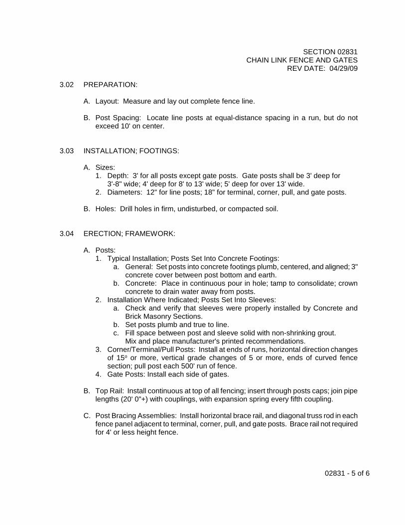
3.02 PREPARATION:
A. Layout: Measure and lay out complete fence line.
B. Post Spacing: Locate line posts at equal-distance spacing in a run, but do not exceed 10' on center.
3.03 INSTALLATION; FOOTINGS:
A. Sizes: 1. Depth: 3' for all posts except gate posts. Gate posts shall be 3' deep for
3'-8" wide; 4' deep for 8' to 13' wide; 5' deep for over 13' wide. 2. Diameters: 12" for line posts; 18" for terminal, corner, pull, and gate posts.
B. Holes: Drill holes in firm, undisturbed, or compacted soil.
3.04 ERECTION; FRAMEWORK:
A. Posts: 1. Typical Installation; Posts Set Into Concrete Footings:
a. General: Set posts into concrete footings plumb, centered, and aligned; 3" concrete cover between post bottom and earth.
b. Concrete: Place in continuous pour in hole; tamp to consolidate; crown concrete to drain water away from posts.
2. Installation Where Indicated; Posts Set Into Sleeves: a. Check and verify that sleeves were properly installed by Concrete and
Brick Masonry Sections. b. Set posts plumb and true to line. c. Fill space between post and sleeve solid with non-shrinking grout. Mix and place manufacturer's printed recommendations.
3. Corner/Terminal/Pull Posts: Install at ends of runs, horizontal direction changes of 15o or more, vertical grade changes of 5 or more, ends of curved fence section; pull post each 500' run of fence.
4. Gate Posts: Install each side of gates.
B. Top Rail: Install continuous at top of all fencing; insert through posts caps; join pipe lengths (20' 0"+) with couplings, with expansion spring every fifth coupling.
C. Post Bracing Assemblies: Install horizontal brace rail, and diagonal truss rod in each
fence panel adjacent to terminal, corner, pull, and gate posts. Brace rail not required for 4' or less height fence.

SECTION 02831 CHAIN LINK FENCE AND GATES
REV DATE: 04/29/09
02831 - 6 of 6
3.05 ERECTION; FENCE FABRIC:
A. Fabric: Install on outside of posts, next to property line; one continuous piece wherever possible; stretch taut.
B. Fastenings:
1. At terminal corner pull gate posts, thread tension bars through mesh; secure to posts with bands at 15" on center maximum.
2. Wire-tie fabric to line posts at 16'' on center; to top rail, brace rails, and bottom tension wire at 18" on center.
C. Bottom Tension Wire: Use hog rings to attach fabric to tension wire; install a
turnbuckle each 150' of wire; wire tie to posts.
D. Clearances: Set bottom of fence fabric to maintain stated clear distances. 1. Mow Strip or Earth: 1" to 2"; trench and shape locally to permit uniform top and
bottom alignment of fabric. 2. Asphalt Concrete Paving: Touching surface.
E. Install hook bolt at mid-point between line posts, but not exceeding 5' o.c.
3.06 ERECTION; GATES:
A. Install gates plumb and level to a tolerance of 1/4" in 10'.
B. Install ground-set items in concrete.
C. Adjust hardware to provide smooth operation. Lubricate where required. 3.07 INSTALLATION; MOW STRIPS:
Where fence is not over paving, excavate as required and install 20" wide x 4" deep concrete mow strip under center line of fence. Widen mow strip to join any paralleling walks or paving which are less than 2' 0" distance from fence line. Mow strip is 20" wide x 4" deep.
3.08 ADJUST AND CLEANING:
A. Adjustment: Adjust brace rails and tension rods for rigid installation. Tighten hardware, fasteners, and accessories.
B. Cleaning: Remove excess and waste materials from Project site.
END OF SECTION

SECTION 03200 STEEL REINFORCEMENT
REV DATE: 02/01/01
03200-1 of 4
FRESNO UNIFIED SCHOOL DISTRICT STEEL REINFORCEMENT
PART 1 - GENERAL 1.01 REFERENCE:
Requirements in Addenda, Conditions and Division 1 collectively apply to this work. 1.02 DESCRIPTION:
A. Principal Work Items Are: 1. Rebar. 2. Welded wire mesh. 3. Accessories. 4. Work furnished but installed by another section.
a. Fabricated rebar for masonry. b. Fabricated rebar for site drainage concrete structures.
B. Related Work Specified Elsewhere:
1. Site Drainage: Section 02720. 2. Concrete: Section 03300. 3. Filled Cell Concrete Masonry High Lift Grouting Method: Section 04101. 4. Concrete Unit Masonry: Section 04220.
1.03 SUBSTITUTIONS:
Only written approval of District will permit substitutions for materials specified. Refer to Section 00700, Article 30, Substitutions, for procedure.
1.04 QUALITY ASSURANCE:
A. Requirements of Regulatory Agencies: 1. Codes: Conform to Title 24, CCR and UBC. 2. Off-site Work: Conform to local governing agency requirements.
B. Source Quality Control: Refer to Section 01400, Quality Control, for analysis and
tests required.
C. Reference Standards: Concrete Reinforcing Steel Institute (CRSI) Manual of Standard Practice.
1.05 SUBMITTALS:
A. Reports: For analysis and tests required by Paragraph 1.04, B.
B. Mill certificates. C. Certificate For Off-site Work: Provide for all off-site work, per Paragraph 1.07,
Section 01700, Contract Close-out.

SECTION 03200 STEEL REINFORCEMENT
REV DATE: 02/01/01
03200-2 of 4
1.06 PRODUCT DELIVERY, STORAGE AND HANDLING: A. Deliver reinforcement to project site in bundles marked with metal tags indicating bar
size, length, configuration and building location. B. Handle and store materials to prevent injury or unwanted bends.
C. Store materials on blocking to prevent contact with ground. Do not store materials in
water puddles. 1.07 JOB CONDITIONS:
Sequencing, Scheduling: Coordinate work with trenching for foundations, concrete forming and placement. Schedule delivery of rebar for masonry with respective sections.
PART 2 - PRODUCTS 2.01 MATERIALS:
A. General: Conform to applicable Codes; refer to Title 24, Section 2-2603(f) in particular.
B. Rebar: UBC Standard 26-4, which is based on ASTM A-615; deformed; grade 60
typical, other stresses where noted.
C. Welded Wire Mesh: UBC Standard 26-6, which is based on ASTM A-185; 75,000 psi tensile strength for 10 gauge and larger wire, 70,000 psi tensile strength for 11 gauge and smaller wire. Flat sheets only.
D. Tie Wire: UBC Standard 24-15, which is based on ASTM A-82; annealed steel, 16
gauge minimum.
E. Accessories: 1. General: CRSI Standards for chairs, spacers, supports and other accessories. 2. Support Blocks For Rebar and Welded Wire Mesh: Dense precast concrete.
2.02 FABRICATION OF REBAR:
A. General: Per CRSI Standards.

SECTION 03200 STEEL REINFORCEMENT
REV DATE: 02/01/01
03200-3 of 4
B. Fabricate to lengths and shapes required. 1. Bends: Bend cold around a pin; minimum diameter shall conform to Title 24,
Section 2-2607(b) and Table 2-26C. 2. Do not bend or straighten bars in a manner, which will injure material.
PART 3 - EXECUTION 3.01 INSTALLATION:
A. Scope: 1. Install all steel reinforcement for concrete work. 2. Install all dowels in concrete, to match locations of masonry wall reinforcement.
B. General:
1. Conform to codes. 2. Do not use rebar, which has bends or kinks other than those required. 3. Do not heat, bend, cut, or alter rebar at Project site without concurrence of
District.
C. Placement; Rebar: 1. Accurately position rebar; securely anchor against displacement. 2. Support rebar above earth or previous concrete pour on concrete support blocks. 3. Support rebar above forms on vinyl coated metal chairs, plastic chairs or stools.
Anchor securely to maintain required clearances from form faces. 4. At columns or piers, do not drive nails into outside forms to support rebar, nor use
any other supporting device, which will contact outside form.
D. Spacing; Rebar: Maintain following minimum clear distances between bars, or greater distances where required. 1. All Cases: 1 1/2" minimum. 2 Parallel Bars (except at splices): 1 1/2 times nominal diameter.
E. Clearances; Rebar: Maintain following minimum clear distances to provide concrete
coverage for protection of rebar, or greater distances where required. 1. Footing surfaces poured directly on earth: 3" 2. Walls against earth, but placed in forms: 2" 3. Walls formed (except [2] above): 1-1/2" 4. Columns, 2" to main steel.
F. Splices; Rebar:
1. Splice only at approved locations. 2. Lap splices: Wire tie securely together.
a. Use typically for splices, corners, intersections. b. Minimum lap distance, unless otherwise required:
1. Concrete: 30 bar diameters, but not less than 24" in any case. 3. Other splice methods: Only with specific District approval.

SECTION 03200 STEEL REINFORCEMENT
REV DATE: 02/01/01
03200-4 of 4
4. Separate splices code-required distances.
G. Welded Wire Mesh: 1. Install in longest practicable length. 2. Lap adjoining pieces one full mesh minimum, and tie splices with 16 gauge wire. 3. Offset laps in adjacent widths to prevent continuous laps. 4. Where mesh is 12" x 12" or greater, support on precast concrete blocks spaced
3', maximum, o.c. each way. 3.02 FIELD QUALITY CONTROL:
Inspection: Refer to Section 01400, testing and inspection requirements. 3.03 ADJUSTMENT AND CLEANING:
Just prior to concrete placement, clean reinforcement free of coatings, rust, scale, that will reduce or destroy bond. Reinforcement appreciably reduced in section by cleaning shall be replaced as directed by District. Reposition any misaligned reinforcement.
END OF SECTION

SECTION 03300 CAST-IN-PLACE CONCRETE
REV DATE: 02/01/01
03300-1 of 17
FRESNO UNIFIED SCHOOL DISTRICT CAST-IN-PLACE CONCRETE
PART 1 - GENERAL 1.01 REFERENCE:
Requirements in Addenda, Alternates, Conditions and Division 1 collectively apply to this work.
1.02 DESCRIPTION:
A. Principle Work Items Are: 1. Concrete Work:
a. Rough concrete. b. Finish concrete. c. Specially finished concrete. d. Bases for light poles. e. School name sign with cast-in letters. f. Grouting at folding panel partition sills.
2. Formwork. 3. Curing and protection. 4. Plastic membrane. 5. Off-site work:
a. Sidewalks, driveways, curbs and gutters. 6. Work installed but furnished by another Section:
a. Setting rough hardware and other embedded items. b. Setting grates and frames for areaways.
B. Related Work Specified Elsewhere:
1. Furnishing rough hardware and other embedded items: Respective Sections. 2. Earthwork: Section 02200. 3. Site Drainage Concrete Structures: Section 02720. 4. Chain link fences, footings and mow strips: Section 02831, Chain Link Fences
and Gates. 5. Steel Reinforcement: Section 03200. 6. Filled Cell Concrete Masonry High Lift Grouting Method: Section 04101. 7. Concrete Unit Masonry: Section 04220. 8. Structural Steel: Section 05120. 9. Bituminous Dampproofing, at planters and retaining walls: Section 07160.
10. Door sills: Respective Sections. 11. Rough concrete encasement for certain piping systems and concrete thrust
blocks for piping systems: Various Sections of Division 15. 12. Rough concrete encasement for underground electrical conduits: Various
Sections of Division 16. 13. Identifying Devices: Section 10400.

SECTION 03300 CAST-IN-PLACE CONCRETE
REV DATE: 02/01/01
03300-2 of 17
1.03 SUBSTITUTIONS: Only written approval of the District will permit substitutions for materials specified. Refer to Section 00700, Article 30, Substitutions, for procedure.
1.04 QUALITY ASSURANCE: A. Design criteria; formwork:
1. Contractor shall be solely responsible for all formwork and Contractor shall: a. Design, construct and maintain formwork to safely support all loads. b. Obtain Governing Agency approval when such is required.
B. Testing Agency:
1. On-site work: District designated testing laboratory. 2. Off-site work: Governing Agency approved testing laboratory.
C. Requirements of Regulatory Agencies:
1. Codes: Conform to Titles 21 and 24 of the CAR and conform to U.C. 2. Off-site work:
a. Conform to Local Governing Agency requirements. b. Obtain and pay for all permits, licenses and fees. c. Arrange for all tests and inspections.
D. Tests and Inspection: General: Refer to Section 01400.
E. Allowable Tolerances for Concrete Surface Smoothness: 1/8" maximum permissible
variation from a true plane measured from a 10' straight edge placed anywhere on the surface, non-cumulative.
F. Job Mock-Ups:
1. General: a. Make samples on-site; revise as required; obtain District's approval,
10 days prior to casting finished work. b. Finished work to match approved samples. c. Approved sample may be incorporated into the work.
2. Specially Finished Concrete: Flatwork: a. Sample size: 20 SF minimum. b. Required for following finishes: Salt.
3. Specially Finished Concrete; School Name Sign: a. Sample size: 2 SF minimum wall area. b. Required for following finishes: Sandblasted.
G. Source Quality Control: 1. Testing laboratory shall provide continuous inspection at concrete batch plant for
all structural concrete, defined as follows: a. Footings, foundation walls, floor slabs-on-grade, exterior reinforced slabs. b. Walls.
2. Furnish Weighmaster's Certificates for all concrete.

SECTION 03300 CAST-IN-PLACE CONCRETE
REV DATE: 02/01/01
03300-3 of 17
1.05 SUBMITTALS: A. Shop Drawings for Cast-in Letters: Full-size template layout of wording for school
name sign.
B. Concrete Design Mix: By testing laboratory.
C. Test Reports: Source and Field Quality Control tests.
D. Certificates: 1. Weighmaster's Certificates: Per Office of the State Architect requirements. 2. Certificate For Off-site Work: Provide for all off-site work, per Paragraph
1.06 PRODUCT DELIVERY, STORAGE AND HANDLING:
A. Storage; Concrete Materials: 1. Cement: Store in weather tight enclosures and protect against dampness,
contamination and warehouse set. 2. Aggregates
a. Stock pile to prevent excessive segregation or contamination with other materials or other sizes of aggregates.
b. Use only one supply source for each aggregate stock pile. 3. Admixtures:
a. Store to prevent contamination, evaporation or damage. b. Protect liquid admixtures from freezing or harmful temperature ranges. c. Agitate emulsions prior to use.
B. Delivery: Ready-Mixed Concrete: Conform to Title 24, Section 2-2605(b)
(which refers to U.C., Standard 26-13).
C. Formwork Materials: 1. On delivery to job-site, place materials in area protected from weather. 2. Store materials above ground on framework or blocking and cover with protective
waterproof covering providing for adequate air circulation or ventilation. 3. Handle materials to prevent damage.

SECTION 03300 CAST-IN-PLACE CONCRETE
REV DATE: 02/01/01
03300-4 of 17
1.07 JOB CONDITIONS: A. Environmental Requirements:
1. Allowable Concrete Temperatures: a. Cold Weather: When depositing concrete in freezing or near-freezing
weather, concrete mix temperature shall be between 50o and 900 F when cement is added. Maintain a concrete temperature of 50o F. minimum for 72 hours minimum after placing or until concrete has thoroughly hardened. When necessary, heat concrete materials before mixing. Take necessary precautions to protect transit-mix concrete.
b. Hot Weather: 90o F. maximum.
B. Protection: 1. Do not place concrete during rain, sleet, or snow unless protection is provided. 2. After placement, protect from injury by elements, traffic, construction operations
and other causes.
C. Sequencing, Scheduling: Coordinate work with earthwork, trenching for foundations, underground utilities, plumbing, electrical, mechanical, Section furnishing imbedded items, steel reinforcement and related work of other Sections.
PART 2 - PRODUCTS 2.01 MATERIALS; GENERAL:
Conform to Codes and additional requirements stated herein. 2.02 BASIC CONCRETE MATERIALS:
A. Portland Cement: 1. Type I or 11; per Title 24, Section 2-2603(c), which refers to U.C., Standard
26-1 and ASTM C150. 2. Use tested cement only. Use same cement brand for all exposed work.
B. Water: Clean, fresh, free of injurious amounts of minerals, organic, substances,
salts, acids or alkali.
C. Aggregates: 1. General: Per Title 24, Section 2-2603(d), and U.C., Standards. 2. Hardrock Aggregates: Per U.C. Standard 26-2 (which refers to ASTM C33).
a. Fine: Sand well graded from coarse to fine. b. Coarse: Uniformly graded from 1/4" to maximum permissible size. Maximum
size per Title 24, Section 2-2603(d) (3), but not to exceed 1" in any case. 3. Lightweight concrete: Per U.C. Standard 26-3 (which refers to ASTM Standard
C330-80). 2.03 MATERIALS; CONCRETE ADDITIVES:
A. Admixtures:

SECTION 03300 CAST-IN-PLACE CONCRETE
REV DATE: 02/01/01
03300-5 of 17
1. General: Inclusion in concrete mix is at the Contractor's option and expense. 2. Types:
a. Conform to Title 24, Section 2-2603(9), which refers to U.C., 26-9 (which is based on ASTM C260, C494, C618). Admixtures shall increase workability and reduce water demand.
b. Acceptable Products: 1. Floor slabs-on-grade: Red Label or Anti-Hydro.
2.04 MATERIALS; CONCRETE SURFACE TREATMENTS:
A. Liquid Curing Compounds: 1. General: Conform to ASTM C309. 2. Acceptable Manufacturers: Hunt Process Co., Burke Co., Scofield Sonneborn. 3. Black, Permanent Type (for areas to receive resilient flooring or carpet):
a. Hunt Black, as a standard of quality. 4. Clear, Oxidizing Type (for areas to be exposed, interior or exterior):
a. Hunt Clear No. ARB as a standard of quality.
B. Floor Hardeners: 1. Color Hardeners; Dry shake:
a. Color: Natural gray. b. Acceptable manufacturers and products:
1. Scofield Co., Lithochrome, as a standard of quality. 2. Master Builders, Colorcon. 3. Sonneborn, Harcol.
C. Abrasive Grains:
1. Type: 60% minimum aluminum oxide abrasive, ceramically bonded to vitrification, neutral color, homogeneous, rustproof; crushed and graded from 1/32" to all passing 1/4" screen.
2. Acceptable Manufacturers and Products: a. Norton Co., Alundum Fine DF, as a standard of quality. b. Scofield Co., Lithochrome Abrasive Grains.
2.05 MATERIALS: CONCRETE JOINTS:
A. Metal Joint Form/Screed: 1. Type: 24 gauge galvanized formed steel, tongue and groove design, 7/8"
diameter rebar knockouts at 6" on center; depth equal to slab depth. Complete system with form/screed, stakes, splice plates, clips and all accessories.

SECTION 03300 CAST-IN-PLACE CONCRETE
REV DATE: 02/01/01
03300-6 of 17
2. Acceptable manufacturers and products: a. Burke, Keyed Kold, as a standard of quality. b. Greenstreak, No. 500 Series, Joint Screed. c. Heckmann, No. 95, Tongue and Groove Joint. d. Jahn, Screed Key Joint.
B. Zip-top Control Joints:
1. Type: Extruded one-piece plastic T-shape, removable zip-off top. 2. Acceptable manufacturer, Zipcap.
C. Expansion Joints; Asphalt Impregnated Fiber:
1. Type: Cane fiber, p e-formed, waterproof asphalt impregnated; 1/2” thick x slab depth; per AASHO M213.
2. Acceptable Manufacturers and Products: a. Burke Co., Fiber Expansion Joint. b. Sonneborn, Sonoflex.
2.06 MATERIALS; SPECIALLY FINISHED FLATWORK:
Rock Salt: Commercial coarse granular-type, (similar to that used in water softening systems) sized from 1/4" to 3/8", with 65% 3/8" in size.
2.07 MATERIALS; WOOD FORMWORK:
A. Grade Marks and Rules For Lumber and Plywood: Per Section 06100, Rough Carpentry.
B. Framing Lumber; General: Douglas Fir; Standard Grade Light Framing or better. C. Boards for Unexposed Concrete and Basic Forms: Douglas Fir, S4S; Standard
Grade or better.
D. Plywood: 1. For unexposed concrete and basic forms: Douglas Fir; Exterior Grade C-C or
better. 2. For exposed concrete: Douglas Fir Plyform, Exterior Class 1; B-B wood face or
high density overlay sheet (HDO).
E. Form Ties; Typical: 1. Type: Snap-ties, carbon steel, 1/4" maximum diameter, 1" minimum break back,
5,000 lb. minimum strength; adjustable or accurately sized. 2. Acceptable manufacturers and products:
a. Burke, Penta-Tie, as a standard of quality. b. Concrete Tie, Contac.
F. Form Coatings and Release Agents--Types:
1. Per manufacturer's recommendations, suitable for type of form materials and finished concrete surface.

SECTION 03300 CAST-IN-PLACE CONCRETE
REV DATE: 02/01/01
03300-7 of 17
2. Materials shall not stain or change color of exposed concrete. 3. Materials shall be compatible with finishes to concrete.
G. Chamfers and Control Joints:
1. General: Wood or plastic, saw kerf backs, 15 taper sides, width or least equal to depth, configurations as required.
2. Chamfers: 3/4"minimum width. 2.08 MATERIALS; ACCESSORIES AND MISCELLANEOUS:
A. Leveling Filler For Floor Slabs: 1. Type: Liquid latex compound and filler powder. 2. Acceptable manufacturers and products:
a. Flintkote, Latex Underlayment Binder and Powder. b. Dowman Products, Fixallatex latex underlayment. c. Webtex No. 660 Latex Underlayment.
B. Nailing Blocks and Other Embedded Wood: Pressure-treated Douglas Fir, per
Section 06100.
C. Plastic Membrane At Slabs: 1. Type: Polyethylene film, 8 mils thick minimum; with manufacturer's
recommended self-adhesive joint tape. 2. Acceptable manufacturers and products: Visqueen, Moistop, Durathene.
D. Sand for Sandblasting: Hard, sharp, quartz sand.
E. Non-Shrink Grout Por-Rok by Hallemite Co; Masterflow No. 713 Grout by
Master Builders; Lithochrome, TRU Grade, by Scofield.
F. Cast-in Letters for School Name Sign: Wood block style letters similar to West-On Letters, Inc. products.
2.09 MIXES; CONCRETE:
A. Mix Proportioning: 1. General:
a. Designed Mix, per Title 24, Section 2-2604(c), by Method B; for all concrete. b. Mix design by designated Testing Laboratory. c. Design shall include all admixtures and/or additives, if any. Use as approved
by the Office of the State Architect. d. Do not add salt, chemicals, or other materials to mix to prevent freezing.
2. Strengths, Proportions and Criteria: a. 2,500 psi Concrete: Typical for all locations; except where higher strengths
are indicated. 1. Strength: 2,500 psi and 28 days; 1,500 psi at 7 days. 2. Cement content, minimum 5-1/4 sacks (94#) cy. 3. Slump maximum: 4".

SECTION 03300 CAST-IN-PLACE CONCRETE
REV DATE: 02/01/01
03300-8 of 17
B. Mixing:
1. General: Per Title 24, Section 2-2605 and U.C., Standard 26-13 (which refers to ASTM C94).
2. Batch Mixed: Use ASTM C94 batch mixer; or capacity to handle one or more full sack batches. No split-sack batches.
3. Transit Mixed: Per U.C., Standard 26-13. 4. Mix concrete only in quantities necessary for immediate use. 5. Do not retemper concrete. 6. Discharge all wash water from mixer before reloading. 7. Include additives and admixtures.
2.10 MIXES; DRYPACK:
A. Mix Proportions: One part cement, 1 1/2 parts sand (fine aggregate).
B. Mixing: With sufficient water to make a stiff mixture, which can be molded by hand into a sphere.
2.11 MIXES; GROUT MIX FOR SACKED FINISH:
A. Mix Proportions: One part cement, 1 1/2 parts fine sifted sand.
B. Mixing: With sufficient water, to the consistency of thick paint. PART 3 - EXECUTION 3.01 INSPECTION:
A. Examine excavations for foundations, footings, structures and examine earthwork operations and subgrade for defects that will adversely affect the execution and quality of work.
B. Do not start work until unsatisfactory conditions are corrected.
3.02 PREPARATION:
A. Layout: Accurately lay out work to properly position all elements to lines and levels.
B. Joining to Previous Pours or Existing Work: Sandblast, roughen and clean existing joining concrete and rebar surfaces to provide a proper bond to new work.
3.03 WOOD FORMWORK:
A. Scope: 1. General: All concrete shall be cast-in forms. 2. Footings: When specifically approved by District/Engineer and the Office of the
State Architect, earth banks may be used as forms in lieu of wood forms.
B. Form Face Types:

SECTION 03300 CAST-IN-PLACE CONCRETE
REV DATE: 02/01/01
03300-9 of 17
1. Unexposed Concrete: Plywood or horizontal boards. 2. Exposed Concrete:
a. General: All new materials, or materials reconditioned to like new. b. Typical Work: Plywood panels, 4' x 8' typical size. Layout symmetrically, long
diameter vertical; panels stacked; all joints aligned, level, plumb, and tight.
C. General Construction: 1. Forms shall be substantial, unyielding, true to line and level; sufficiently tight to
prevent leakage of mortar; adequately tied and braced; and conform exactly to dimensions of finish concrete.
2. Forms shall provide adequate work clearances, temporary access openings necessary for concrete placement, provisions for attachment to previous work; and provide for stripping without injury to concrete work.
3. Cleanouts: Provide continuous cleanouts on one side at bottom of vertical work (such as walls), and other openings as necessary to facilitate cleaning and inspection of the work.
D. Fabrication:
1. Nail board and/or plywood form faces securely to studs. Space studs to adequately support form faces and prevent bulging. Provide stud or solid backing at all joints.
2. Install chamfer strips at all exposed corners and edges. 3. Securely fasten chamfers, control joints and other detail work.
E. Erection:
1. General: Erect formwork plumb and level; double wales; adequately brace, shore and support; set so finished concrete surfaces will drain.
2. Ties and Spreaders: a. General: Position to securely anchor forms; maintain accurate wall
dimensions, true surfaces and prevent bulging. b. Exposed Concrete: Position in similar symmetrical patterns.
3. Footings and Foundation Walls: Form both sides; secure to stakes. 4. Walls: Form both sides; set so tops of exposed work will be a straight, level line.
F. Form Coatings and Release Agents: Apply, per manufacturer's recommendations, to evenly coat all contact surfaces.
3.04 INSTALLATION; EMBEDDED ITEMS:
A. General: 1. Install per Title 24, Section 2-2606 (c) and U.C., 2606(c). 2. Place accurately; anchor securely to prevent displacement. 3. No wood to be permanently embedded in concrete, except where indicated. 4. Coordinate, notify, provide access for other Sections to set their required work.
3.05 INSTALLATION; GRATES AND FRAMES FOR AREAWAYS:
Install accurately, level, at proper elevations, securely anchored, and with all fastenings in place.

SECTION 03300 CAST-IN-PLACE CONCRETE
REV DATE: 02/01/01
03300-10 of 17
3.06 INSTALLATION; SCREEDS FOR SLABS, WALKS AND FLAT WORK:
A. General: 1. Set and securely support screeds accurately to lines, levels and grades required
for finished work. 2. Where membranes occur, supports shall not puncture membranes. 3. Spacing: 8' 0" on center typically; closer intervals where construction conditions
require.
B. Permanent Metal Joint Form/Screeds: 1. Scope: Install in all exterior slabs, walks, paving and flatworm. 2. Spacing/Location: 20'-0" on center maximum each way; all points where concrete
changes direction; and where indicated. 3. Installation: Burke Keyed Kold system, as a standard of quality.
a. Stakes: Space 2'-0" on center typical, and 6" maximum from ends of runs. b. Screeds: Hang screeds on stakes, crimp top leg into hole in stake, clip
bottom leg to stake, butt joints and install splice plates. c. Coating: Oil screeds prior to concrete placement. d. When concrete pour is against one side only, bend knock-out tabs into pour
at 45o approximate. 3.07 INSTALLATION; PLASTIC MEMBRANE:
A. Scope: 1. Install under all interior floor slabs on-grade.
B. Installation: 1. General: Place over prepared 2" sand over compacted earth, cover with 2" sand,
prior to steel reinforcement placement. Use as large sheets as practicable. Cut and fit neatly around all penetrations.
2. Joints: Lab 6" typical; lap floor sheets 2' 0" minimum over footing sheets. 3. Taping: Spot tape joints to hold sheets in place. Tape seal all punctures and
around all penetrations and all lap joints.
3.08 PREPARATION; CONSTRUCTION JOINTS: A. General:
1. Comply with Title 24, Section 2-2606(d) and U.C., 2606(d). 2. Locate joints where they will least impair strength of structures. 3. For joints at locations other than those indicated, obtain District/Engineer
approval.
B. Preparation: 1. Clean and roughen entire joint face to remove entire surface and expose clean
aggregate solidly embedded in mortar matrix by one of the following methods. a. Sandblast or chip, not earlier than five days after initial pour. b. Hose wash clean between two and four hours after concrete is placed.
Remove all wash water, laitance and debris.

SECTION 03300 CAST-IN-PLACE CONCRETE
REV DATE: 02/01/01
03300-11 of 17
2. Vertical Joints: Wet and flush with neat cement grout, just prior to concrete placement.
3. Horizontal Joints: Wet and deposit 2" to 6" layer of specified modified concrete mix, prior to placing regular mix.
3.09 PREPARATION; SLABS-ON-GRADE:
Tamp sand sub-base to a firm unyielding surface. 3.10 CONCRETE PLACEMENT:
A. General: Comply with Title 24, Section 2-2605 and U.C., 2605.
B. Preparation and Inspection Prior to Concrete Placement: 1. Preparation--do not place concrete until:
a. Footing excavations are cleaned and dry. b. Steel reinforcement is correctly positioned, securely anchored and cleaned. c. Forms are cleaned, coated, and ties are tightened. d. Embedded items are positioned and anchored. e. Construction joints are cleaned and prepared. f. Subgrade is prepared and moistened. 9. All preparations for a pour are completed. h. Work has been inspected.
2. Inspection: All formwork, steel reinforcement, footing excavations and preparation work (as stated in Paragraph No. 1.02. A) to be inspected and approved by District/Engineer, prior to pouring any concrete.

SECTION 03300 CAST-IN-PLACE CONCRETE
REV DATE: 02/01/01
03300-12 of 17
C. Placement: 1. Convey concrete from mixer to final position by method, which will prevent
separation or loss of material and cause minimum handling. 2. Deposit concrete in continuous operation will panel or section is completed. 3. Regulate rate of placement so concrete remains plastic and flows into position. 4. Keep tops of vertical lifts approximate level during placement. 5. Maximum permissible free-fail for concrete is 3'. Use elephant trunks or other
approved means necessary to meet this limitation. 6. Maximum permissible thickness of concrete layers is 2'. 7. Where reinforcement is congested or consolidation is difficult, specified modified
concrete mix may be used in a 2" to 6" layer. 8. Special conveyance and placement methods may be used with prior approval of
District/Engineer and the Office of the State Architect. 9. Do not use partially hardened or contaminated concrete; do not retemper
concrete; or do not use concrete, which has been remixed after initial set.
D. Consolidation: 1. Use mechanical vibrating equipment. Supplement with hand rodding, spading
and tamping. 2. Vertically insert and remove hand-held vibrators. 3. Work concrete thoroughly around reinforcement, embedded items and into all
parts of forms. 4. Consolidate to a dense, uniform mass without voids, rock pockets, or entrapped
air. Consolidate each layer.
E. Slabs, Walks and Flatworm: 1. Lift reinforcement as placement progresses to proper position in slab. 2. Tamp and screed to required lines and levels. 3. Depress coarse aggregate with grille-blade tamper.
3.11 FINISHING FLATWORK; TYPICAL:
A. Scope: Finish all flatworm as specified herein. B. Interior Slabs:
1. General: a. Monolithically finish all slabs. b. Do not dust with dry cement to remove water.
2. Floating: a. Power float upon disappearance of water shown. b. Hand float areas inaccessible to power float.
3. Trowel Finishing: a. Areas depressed for ceramic and quarry tile: Further finishing is not required. b. Areas to receive carpet and resilient floor coverings: Power trowel to a
dense, smooth, even surface, until no more excess water may be brought to surface.
c. Exposed concrete areas: Gray color hardened.

SECTION 03300 CAST-IN-PLACE CONCRETE
REV DATE: 02/01/01
03300-13 of 17
1. Just prior to floating, evenly apply 20 Ibs. hardener per 100 SF. 2. After floating, spot touch-up uneven areas; then evenly apply ten Ibs.
hardener per 100 SF. 3. First Troweling: Power trowel per Paragraph B above. 4. Hand steel trowel (causing trowel to ring) to a smooth, slick, burnished
surface, free of defects and blemishes.
C. Exterior Flatworm (slabs, walks, paving and similar work): 1. General:
a. In indicated areas, finish concrete as specified herein, in lieu of typical finishes.
b. All work to match approved samples. c. The Contractor is to limit pour areas and provide sufficient ratio of finishers to
produce specified finishes. 2. Sweated Finish; Typical:
a. Two steel troweling IS, while concrete is still green. b. Non-slip sweated finish with regular light trowel marks in an approximately 2'
circular arc pattern. 3. Salt Finish; where Indicated:
a. Preparation: Screed and float. Steel trowel smooth and even in circular arc pattern, free of blemishes and ridges.
b. Salt Application: 1. While concrete is still plastic evenly and uniformly seed surface at 10 Is.
minimum per 100 SF; 3" maximum between pockmarks any where on surface.
2. Press, roll or trowel salt grains to embed them flush with concrete surface; do not shatter salt grains.
3. After concrete sets, completely dissolve and wash salt away from planting areas.
4. Marking: a. Type; Typical: V-groove radius tool. b. Patterns: Follow indicated patterns; where not indicated, mark as follows:
1. Walks: Into squares, equal to walk width. 2. All areas 8' or wider: Into approximate squares, 8' maximum diameter.
5. Tooling: Radius tool all exposed edges, edges adjacent to all permanent wood headers and edges at each side of all metal joint screeds.

SECTION 03300 CAST-IN-PLACE CONCRETE
REV DATE: 02/01/01
03300-14 of 17
D. Abrasive Surface Treatment: 1. Scope: Apply to all exterior and interior exposed concrete steps and ramps and
where indicated: a. Ramp defined as surface sloping 2" or steeper.
2. Application: Apply evenly at 25 Is. per 100 SF just prior to final troweling Tamp and trowel to securely embed, but not cover abrasive.
3.12 FLATWORK CONTROL JOINTS:
A. General: Conform to Title 24, Section 2-2606(d). B. Interior Slabs-on-Grade:
1. General: Create construction joints to divide slabs into 400 SF maximum approximate rectangular shapes, by any of the following methods. a. Alternate pours, checkerboard pattern. b. Saw cutting within 12 hours from time of pour. c. Install Zip-Top control joints concurrently with tamping and floating work.
Using sawing motion, push straight-edge into concrete to form groove. Insert Zip-Top control joint into groove, using sawing motion, until joint top is flush with concrete surface. When concrete sets sufficiently, pull-off removable top flange.
2. Location: Locate joints typically to occur under partitions, avoid exposed concrete floor areas; align with structural features, points where slab changes configuration or direction and points where stresses localize.
C. Exterior Flatworm (Walks, Paving and Similar Work); General: Construction joints
formed by permanent Metal Joint Form/Screeds per Paragraph 3.06 B. 3.13 FORMWORK REMOVAL:
A. General: Do not remove or disturb forms, shoring or bracing until concrete has hardened sufficiently to permit safe removal, support all imposed loads including its own weight, nor in any case until the following minimum times have elapsed: 1. Foundation Walls: Three days. 2. Slabs-On-Grade: Three days. 3. Walls: Three days.
B. Ties: Remove or snap-off ties, spreaders, tie rods, and other devices so no metal is
left within 1" of concrete face.
C. Exposed Concrete Work: Carefully remove formwork and detail strips so surfaces, corners, edges, details, and all features will be true, level, sharp, unbroken, unmarred or damaged in any way.

SECTION 03300 CAST-IN-PLACE CONCRETE
REV DATE: 02/01/01
03300-15 of 17
3.14 PROTECTION AND CURING OF CONCRETE: A. Protection: Protect all work from injury and defacement of any nature during
construction operations.
B. Curing: 1. General:
a. Keep concrete surfaces wet until curing medium is applied. b. Cure drypack same as concrete.
2. Walls, Mass and Reinforced Concrete:
a. Scope: Maintain in a thoroughly wet condition all forms containing concrete, top of concrete between forms, all exposed concrete surfaces after removal of forms.
b. Time Period: Wet continuously each day for 10 consecutive days, including Saturdays, Sundays and holidays.
3. Flatwork: a. Scope: Apply specified liquid curing compounds to all interior floor slabs, and
all exterior flatworm (slabs, walks, paving, and similar work). b. Application: Apply uniform, continuous, tightly adhered film, free from
pinholes or defects at rate of 1 gallon per 250 SF. 3.15 FINISHING WALLS AND VERTICAL CONCRETE SURFACES; TYPICAL:
A. Scope: Finish all walls and vertical concrete surfaces as specified herein, except for school name sign.
B. Exposed Concrete At Tops of Forms:
1. Strike concrete smooth and level. 2. Float and/or trowel to texture comparable to formed surfaces.
C. Preparation, Formed Surfaces:
1. Remove fins and irregularities while concrete is green. 2. Tie Holes: Fill full and flush with compacted drypack. 3. Surface Defects:
a. Cut out blemished and defective areas as directed by the District. b. Patch flush with drypack, typically, or as directed by the District.
D. Cleaning:
1. Exposed Surfaces: a. Remove form coatings, bond breakers and other surface coatings. b. Scrub form surfaces with solution of 1 1/2 lbs. caustic soda per 1 gallon water. c. Scrub smooth wood or waste mold areas with 20% muriatic or hydrochloric
acid solution. d. Wash surfaces clean with clear water, immediately after scrubbing. e. If above methods fail to remove all substances, lightly sandblast surfaces
clean as directed by the District.

SECTION 03300 CAST-IN-PLACE CONCRETE
REV DATE: 02/01/01
03300-16 of 17
2. Surfaces With Finish Materials Applied Directly to Concrete: Clean as stated for Exposed Surfaces, except where uncleaned surface will not affect application, bond, performance or appearance of finish materials.
E. Sacked Finish For All Exposed Concrete:
1. General: Schedule work to complete entire panel, element or area in one continuous operation.
2. Application: a. Wet surface to control suction of water from grout. b. Apply grout mix; uniformly spread and scour to fill depressions. c. While still plastic, sponge rubber float finish surface and remove excess
grout. 3. Sacking: Allow surface to dry, but not completely harden; then rub vigorously with
clean dry burlap to remove loose excess material. Finished surface to have a smooth slick burnished finish (similar to a steel trowel finish), which is free of defects and blemishes.
3.16 PREPARATION OF HORIZONTAL CONCRETE SURFACES TO RECEIVE
MASONRY WALLS: Prepare and roughen as specified for horizontal concrete construction joints in Paragraph 3.08, B, 1.
3.17 SCHOOL NAME SIGN; CAST-IN LETTERS:
A. Accurately set letters in place; space to match approved Shop Drawings. Coat with bond breaker. After concrete hardens, carefully remove wood letters to leave sharp, clean recesses in the concrete.
B. Sandblast Finish:
1. General: a. Scope: Heavily and uniformly sandblast to expose coarse aggregate. b. All work to match approved samples. c. Complete entire side in one continuous operation.
2. Preparation: Per Paragraphs 3.15, B and C. 3. Sandblasting:
a. Wet or dry processes, as permitted by Local Governing Ordinances. b. Control dust from drifting to adjacent areas. c. Where wet process is used, build dams and otherwise control and direct flow
of run-off water. 4. Cleaning:
a. Wash down all blasted surfaces with clear water to remove dust, sand and leave them clean.
b. Remove all blasting sand and debris. 3.18 FIELD QUALITY CONTROL:
A. General: Refer to Section 01400, Testing and Inspection.

SECTION 03300 CAST-IN-PLACE CONCRETE
REV DATE: 02/01/01
03300-17 of 17
B. Inspections: 1. Steel reinforcement. 2. Structural concrete.
C. Tests:
1. Concrete slump. 2. Making concrete compression test cylinders. 3. Core tests of defective work.
3.19 ADJUSTMENT AND CLEANING:
A. Correction of Defective Work: 1. General: Work not conforming to Contract requirements shall be removed and
replaced; except where patching or other remedial work is specifically permitted by the District. The Contractor shall bear all costs of correction of defective work. a. Surface patching materials and methods shall be as approved by the
Architect. b. Structural concrete replacement, strengthening, and/or repair methods and
materials shall be as approved by District/Engineer and the Office of the State Architect.
2. Filling and Leveling Slab Surfaces to Receive Resilient Flooring or Carpet: a. High Spots: Remove, hone or power grind to required levels. b. Low Sports: Fill to required levels with specified Leveling Filler, mixed and
applied manufacturer's recommendations.
B. Cleaning: Clean exposed surfaces just prior to acceptance.
END OF SECTION


17_0602_WawonaPreK_004
Wawona Pre-KindergartenFresno, CA.06-01-2017

17_0602_WawonaPreK_004
Wawona Pre-KindergartenFresno, CA.06-01-2017


Sub-Surface Preparation - Concrete
4393 Discovery Line, P.O. Box 239, Petrolia, ON N0N 1R0 T: 800 263 2363 F: 519 882 2697 E: [email protected] www.sofsurfaces.com
Leaders in Fall Protection
When planning to install SofTILE over a concretesurface it is important to keep the following guidelines and requirements in mind for the preparation of the sub-surfacing and curbing.
• The intent of any sub-surface for the tiles is that the surface needs to be firm and smooth.• Typically sloped 1% to allow for water runoff and still meet ADA requirements. Sloping usually occurs from the middle of the site towards the outside edge.• The use of height or grade stakes set every 8 feet to assist with the screeding are helpful in achieving a consistent surface.• It is critical that the concrete surface is smooth (fine to medium broom finish) with minimal undulations. • Any imperfections in the sub-surface show through on the tile surface either immediately or over time. For areas or undulations deeper than ¼ inch and larger than an inch it is recommended to use a concrete or cement type patching material. • The concrete surface specification and drainage requirements will be provided to you by the architect or civil engineer for your project: 1. They should have designed the concrete based on loading, area of the country, the sub-surface, freezing temperatures, etc. 2. The base pad requires 7 to 10 days curing to allow for moisture to dissipate. Adhesive does not stick well to moisture. a) The SofTILE installer should be advised when the concrete pour has been completed and a photo sent showing completion.• Site should be clean and ready when the tile installer arrives.• Make sure no concrete residue is left on the equipment posts. Posts to be clean prior to arrival of the installer and the tile installation.• When using curbs or sidewalks: 1. They have to be designed around the thickness of tile and they need to be consistent in height and width with no greater than a 1/8 inch variance in height. We do not trim the pedestals as that a�ects fall height protection. 2. The top of the curb needs to be parallel to the sub-surface for a distance of 12 inches from the curb. 3. The curb edge against the tile should have a maximum rounded edge of 0 inch (as square as possible). 4. The edge of the concrete curb or sidewalk should be poured at 90 degrees to the surface. The concrete curb should not be wider at the base where it meets the pad.• Drainage on the concrete pad is required: 1. The water needs to be able to run away if under the tiles. 2. Surface drainage if site is sloped will allow water on top of the tiles to run away.• If post holes are drilled on previously installed concrete, or holes are left for posts, the concrete needs to be poured so that a level surface is created. SEE attached photo(s) example of what NOT to do.• Set equipment so the tiles can run under the equipment panels, ramps, etc as it will save considerable time in the tile installation and provides a much nicer finish. This is especially true for rock walls. • Tiles are installed to a 24 inch dimension so it is important that curbing and edging are installed in measurements no greater than 24 inches. Please forward this information to those who are installing the equipment, the asphalt and the curbs or sidewalks. If you have any questions please feel free to call our o�ce.

Leaders inFall Protection.
SofTILE
InterlockingChannel
SofTILE
InterlockingChannel
3/4”
Area of Adhesive Application
M A R C H 2 0 1 4

Introduction......................................................................................1
Product Storage 1. Adhesive...........................................................................................1 2. SofTILE®............................................................................................1 Tools & Consumables Recommended tools & consumables........................................1 Personal protective equipment....................................................1 Optional equipment.........................................................................1
Site Survey 1. Orientation a) Direct sunlight...........................................................................1 b) Continual shade or damp areas.........................................2
2. Subsurface drainage a) Naturally draining subsurface..........................................2 b) Non-draining subsurface................................................... 2 c) Solid subsurface....................................................................2 d) Slope..........................................................................................2 e) Solid retainer...........................................................................2 Site Preparation.............................................................................3
Site Preparation - Pre Subsurface 1. Remove all sod and topsoil......................................................3 2. Install water collection system...............................................3
Site Preparation - Subsurface 1. Test subsurface for proper slope............................................3 2. Test subsurface for proper grade............................................3 3. Repair all variations in grade....................................................3 4. Augering of sites will disturb existing base surfacing.....3 5. Curb heights to be the height of the tile surface or higher.....3 6. Inspect concrete finish - no cracks, loose material..........3 7. Prepare your surfaces for proper adhesion a) Make sure concrete and asphalt surfaces are dry......3 b) Confirm that the concrete or asphalt has fully aged/cured...............................................................................3 c) Mechanically prepare the area as required.................3
Prior to the Installation of Tile 1. Measure the site and record dimensions............................4 2. Check to ensure non-encroachments zones, fall heights, and fall zone clearances............................................4 3. Confirm adequate materials to complete installation....4 4. Atmospheric temperature above 40°F (5°C) & rising......4 5. Watch for variance in color tones...........................................4
The Layout 1. Multicolored surface....................................................................4 2. Take proper measurements prior to commencing with installation............................................................................4 3. Ensuring the installation is square.........................................4 4. Laying the grid lines....................................................................5 5. Coefficient of thermal expansion...........................................5 6. Installing the surface...................................................................5
PAGE
SofTILE® Installation Procedures March 2014
Key Concept Descriptions 1. Keystone tiles...............................................................................5 2. Strategic rows..............................................................................6 3. Compression rows......................................................................6 4. Field tiles ........................................................................................6 IMPORTANT information regarding the placement of keystone tile and strategic rows of tiles.............................7
Beginning Tile Installation Step one - Installation of keystone tiles...................................7 Step two - Installation of strategic rows..................................7 Step three - Compression rows...................................................8 Step four - Installing field tiles......................................................8
Marking and Cutting Tiles Perimeter cutting..............................................................................8 Marking and Cutting Posts................................................9
Cutting Tiles...................................................................................10
Adhering Tiles Key points......................................................................................10 1. Checklist prior to application................................................11 2. Adhesive placement locations.............................................11 3. Tile to tile adhesion..................................................................11 4. Preparing the equipment.......................................................11 5. Application nozzels..................................................................11 6. Adhesive application techniques.......................................12 Key points.....................................................................................12 7. Tile to subsurface adhesion..................................................12
Surface Preparation 1. Concrete surfaces.....................................................................12 2. Asphalt surfaces........................................................................12 3. Traditional edging adhesion................................................13 4. Playground post cuts..............................................................13 5. Adhesion under decks............................................................13
Final Installation Details 1. Remove any adhesive spills a) “Smeared” adhesive spill....................................................13 b) “Bead-shaped” adhesive spill..........................................13 2. Initial appearance and maintenance.................................14 3. Initial odor...................................................................................14 4. Sealant..........................................................................................14
Routine Maintenance 1. Routine maintenance extends life and enhances appearance..................................................................................14 2. Regular cleaning........................................................................14 3. Vacuum.........................................................................................14 4. Cleaning agents.........................................................................14
Advance Maintenance 1. Steam vacuum...........................................................................14 2. Power washing..........................................................................14
Summary.........................................................................................14
Pre-Installation Checklist..................................................15
Installation Inspection Forms..............................16 - 19
PAGE

- 1 -
Product Storage
1. Adhesive Store all manufacturer-supplied adhesives in a dry storage area. Shelf life 12 months.
2. SofTILE®Tiles that will be stored for a long period of time prior to install-ation should be stored indoors. See further notes for storage during installation.
Tools & Consumables
Like any job, your SofTILE® installation will go much smoother with the proper tools. The following list of tools and consum-ables are recommended for your upcoming project:
• Broom • Leaf blower
• Aluminum straightedge 30 inch minimum - black lettering • 24 inch square and speed square – yellow or white lettering • Measuring tape - Imperial measurement units (Tiles are made to Imperial measurements) • Felt-tip marker/paint marker to mark tiles for cutting (Sharpie™ – metallic silver or equal) • Chalk line & refill bottle (black is permanent) • String line • Heavy-duty auto-lock cutter utility knife (Olfa LA-X™ or equal) & replacement blades (LBB UltraMax™ or equal) • Jigsaw (Bosch or equal - minimum 5.5 amp or greater recommended) • Jigsaw blades; 10 teeth per inch minimum - Should be 1/4 inch shorter than the thickness of tile (in saw and when extended) • Templates – for marking postholes for cutting • Polyurethane expansion foam • Duct or masking tape to protect adjacent items during adhesive application • Disposable rags and/or paper towels (adhesive clean up) • Goof Off® (red can), made by Valspar • 18V Cordless adhesive dispensing gun for 20 oz (by volume) tubes - including lithium 1.5 amp hour battery and charger, end cap for orange cone, orange cone nozzle, welded end cap for custom nozzle, custom slotted nozzle, Hytrel plastic piston
• Manual adhesive dispensing gun for 20 oz (by volume) tubes - including end cap for orange cone, orange cone nozzle, welded end cap for custom nozzle, custom slotted nozzle, Hytrel plastic piston • V-Notched trowel with 1/8 inch square notch or 3/16 v notch - plastic or metal trowel - for tile to base adhesive spreading • 8 lb. sledgehammer • Pipe Fittings (3/8 inch), for glue gun Personal protective equipment • Disposable protective gloves (latex, nitrile or other) - for adhesive application • Gloves (general work gloves) • Safety glasses • Hard hat • Knee pads
Optional equipment • Vacuum cleaner • Hot box - for heating of adhesive • Flex curve carpenter
Introduction
The SofTILE® KrosLOCK system has been designed to be installed using specific installation methods developed to ensure the long-term performance of the surface. Each step in the installation process is critical to ensure a successful installation. This manualhas been designed utilizing the best installation techniques taken from various professional SofTILE® installation crews acrossNorth America. The manual was designed to ensure that theSofTILE® surface has been installed according to specification andhas also incorporated the most efficient methods of installation.
Site Survey
1. Orientation
Note: Although the final orientation of the installed surface may not be a matter of choice, some consideration should be given to the following items.
a) Direct sunlight SofTILE® is made from recycled rubber. Rubber absorbs heat fromexposure to direct sunlight, rather than from exposure to atmospheric temperature. If the surface area is exposed to continual direct sunlight,design considerations should include lighter colors that reflect infrared light. (Lighter colored surface will provide a modest impact onsurface temperatures.) Sun exposure is one of the potential safety threats on playgrounds. Any child, youth or adult can suffer from harmful UV rays penetratingtheir skin, or they can be burned by play equipment or rubber surfacingthat has become too hot from sitting in direct sunlight. To avoid these risks, trees and other shading devices can be planned into the designof a playground area for sun protection.

2. Subsurface drainageFor both interior and exterior SofTILE® installations it is important that
the subsurface drains properly. Contact a local expert for your specific
criteria.
a) Naturally draining subsurfaceIf the installation site is elevated with natural drainage, and does
not currently collect water, then additional storm water manage-
ment may not be necessary.
b) Non-draining subsurfaceIf the installation area is lower than the adjacent grades and tends
to collect water, or if water puddles on the subsurface, then a sub-
surface water management system must be installed.
c) Solid subsurfacesIf the subsurface is solid (i.e. concrete or asphalt) and water collects
on the surface deeper than 1/4 inch in any area where the tiles
are to be adhered to the base, these areas must be filled with patch
materials recommended by the concrete or asphalt supplier. (See
surface preparation section.)
d) Slope The subsurface must be sloped 1% towards the water collection drains.
e) Solid retainerAll installations that are bordered with a solid retainer must be
designed with a drainage system to prevent pooling of water.
Note: Insufficient drainage will result in the SofTILE® surface being subjected to standing water for long periods of time. Standing water will damage the SofTILE® surface and void the warranty.
- 2 -
Site Preparation
The ideal subsurface for the SofTILE® KrosLOCK system is properlyprepared concrete or asphalt that is cured, clean, dry and free of oils and moisture. • SofSURFACES® recommends properly cured and installed concrete. • The second preferred alternative is properly aged and prepared asphalt. To ensure proper adhesion the oils in the surface must be removed using a walk behind concrete grinder (see adhesive section for details). • SofTILE® can also be installed over a properly leveled and com- pacted subbase of 4 inches of 3/4 inch minus aggregate, followed by a minimum 1 inch layer of 1/4 inch minus screenings and followed with an EPDM membrane
NOTE: Considerable care and skill is required to properly install a granular subsurface.
Proper preparation of the subsurface is critical to the long-term success of your project. Due to the importance of proper subbase preparation, SofSURFACES® has created a separate instructional manual specifically addressing the correct subsurface preparation techniques required to obtain a surface suitable for a tile installation. Prior to beginning installation work please consult SofSURFACES’® subsurface preparation guide.
Site Preparation - Pre Subsurface
Note: Base preparation and proper drainage are normally covered under a separate contract from the SofTILE® installation. The following information is provided as a brief guideline for those installations that do not have a properly prepared base.
1. Remove all sod and topsoilRemove topsoil until solid, packed and stable subsoil is visibleand level.
2. Install water collection system a) Excavate trenches to contain perforated PVC pipe. Top of PVC pipe should be level with bottom of intended granular base. (PVC pipe is preferred over corrugated plastic drain tile because of the tendency for plastic drain tile to become crushed during its life cycle.)b) Install perforated PVC pipe with correct slope. Connect ends.c) Wrap perforated pipe with landscaping fabric. d) Backfill trenches with 3/4 inch clear stone. This 3/4 inch stoneshould wrap the drainage pipe to a diameter of approximately 12 inches.e) Tie drainage system into existing storm sewer or ditch. Restore finished surfaces over trenched areas with appropriate ground cover (sod, etc.).
Note: A properly designed and installed water collection system is often overlooked during SofTILE® site planning stages. Although the tiles are impervious, water will pass through the corners and seams of the SofTILE® system. It is critical that a proper subsurface drainage system be installed. Failure to do so could result in damage to the subsurface and/or SofTILE® surface. See your Architect or Civil Engineer.
b) Continual shade or damp areasInstallation sites with continual shade may remain damp for long periods of time. During warmer temperatures damp areas may be subject to mold growth. In light of this, tile surfaces in shaded areas with the potential for mold growth should be cleaned periodically..

- 3 -
1. All subsurfaces require proper slope. The proper slope for a SofTILE® installation is 1%.During heavy rains, water will collect on surfaces with slopes
that are less than 1% or if the grade of the surface is not consis-
tent. The surface should be able to accommodate 25-year storm
water volume.
If water collects on any nonporous subsurface (asphalt or con-
crete), the adhesives can be affected over time. If significant
water volumes cannot escape from the subsurface and water
backs up under the tiles, the hydraulic pressure could also result
in a damaged installation.
To test the grade and drainage, flood the area with water and
mark puddles with chalk. Puddles deeper than 1/4 inch and larger
than 1 inch in diameter should be patched.
2. Test subsurface. Frequently, subsurface preparation is completed under separate
contract to the SofTILE® installation. Check the surface to ensure:
a) Aggregate is properly compacted. May become disturbed
in the time between subsurface installation and the SofTILE®
installation. Check under equipment and along curbs.
5. Curb heights are typically specified to be the height of the tile surface. Accuracy is critical. An unlevel subsurface or curb is not cosmetically pleasing. Cutting the base of the tile to match the curb height will reduce the fall height rating and is not recommended.
6. Inspect concrete finish to ensure there are no cracks and/or loose material. Concrete should have a light broom finish for best surface adhesion. A heavy broom finish will result in a higher than normal adhesive usage Ensure that there are no significant cracks and that the area is level.
Note: A properly prepared, cured and dry concrete or asphalt subsurface is the ideal subsurface for SofTILE®.
Note: Clean the site well to ensure you are beginning with a clean level surface.
7. Preparing your surfaces for proper adhesion. a) Concrete – it is important that the surface be completely dryto avoid adhesive failure. SofSURFACES’® installation procedure requires that some tiles be permanently fastened to the sub-surface. Sufficient curing of the concrete normally requires 10 to 15days. Less than 3 lbs moisture per 1000 square feet isideal. Surface must be cleaned prior to adhesion.
Note: If the installation of SofTILE® MUST be carried out before the concrete has sufficiently cured, then certain SofTILES (perimeter, key stone and strategic rows), must be permanently fastened to the subsurface using mechanical methods. Consult SofSURFACES® for options when SofTILE® must be placed on green concrete.
b) Asphalt may require longer curing to allow the oils to dissipate. Most asphalt surfaces contain a significant amount of tars and oil which will prevent sufficient adhesion.
c) Mechanically prepare the area as required. All asphalt areas receiving tile to perimeter adhesive (perimeter tiles, key stone tiles and strategic rows) must be mechanically abraded with a concrete grinder or hand grinder to remove approximately 1/8inch and power wash to remove the oils (Fig 11a).
b) The subsurface contractor may not have taken the care and
necessary steps to achieve a smooth surface.
Note: Any undulation in the subsurface will become more visually apparent in the finished SofTILE® surface.
3. Repair all variations in grade that are greater than +/- 1/4 inch over 10 feet (in any direction)
a) Patch solid subsurfaces with materials recommended by the
concrete or asphalt manufacturer.
b) Aggregate subsurfaces must have a 1 inch layer of properly
leveled and compacted 1/4 inch minus screenings placed over top
of a minimum 4 inch layer of properly leveled and compacted 3/4
inch minus aggregate. EPDM membrane placed only when granular
is correct.
4. Augering of sites will disturb the existing base surfacing. Where concrete/asphalt or granular surfaces have been removed
or disturbed ensure that the areas are well compacted and sloped
away from the posts. These areas should not be lower than the
surrounding areas.
Site Preparation - Subsurface
. Note: For packed aggregate subsurfaces see the guideline pro- vided by SofSURFACES® entitled Subsurface Preparation Guide.

- 4 -
Prior to the Installation of Tile
*SEE ADDENDUM FOR CHECK LIST1. Measure the site and record dimensions 2. Check to ensure non-encroachment zones and fall heights are accurate to the drawings.
3. Confirm adequate materials to complete the installationIt is important to have enough products to complete the entire installation in a single installation session for the following reasons:
a) SofTILE® Plus and SofTILE® Premium, like new wood, concrete, asphalt or painted surfaces will change color withexposure to UV. This change is not as noticeable when all of theinstalled tiles change color at the same time. However, like installing a new piece of wood beside an old one, there will be a noticeable difference in the color tone of tiles installed at separate times.
b) Installing all tiles in one session ensures similarity in install-ation conditions and efficiency.
4. Atmospheric temperature above 40°F (5°C) and risingAtmospheric temperatures should be above 40°F (5°C) for at least 24 hours and preferably climbing. Viscosity, work life and final cure time of the adhesive will vary dramatically with temper-ature. Tile installation is not recommended if/when temperaturesare expected to remain below 45°F (7.2°C) for an extended period of time.
5. Watch for variance in color tones SofTILE® Plus may have a slight variance in color tone from tile to tile. This is due to the recycled nature of the raw materialsused in the production of rubber safety tiles. Visual effects of color variation can be minimized by placing these tiles in a lessvisible area such as under play decks.
SofTILE® Premium may also undergo a temporary color change due to the effects of UV on the thin layer of binding resin on the top of the surface. The thin layer of binding resin will be in-fluenced by UV causing the tile to temporarily darken or yellow. The color change is normal, expected and temporary. The original color tone will be restored within 4-12 weeks depending onweather and usage. The Layout
When preparing for your initial site layout there are some importantfactors to take into consideration: • Each SofTILE® KrosLOCK piece is manufactured to a nominal di- mension of 24.2 inches • The SofTILE® installation process requires that each tile be installed under slight compression to a dimension of 24 inches • It is unlikely that the site is perfectly square or exactly as shown in the drawings. Based on these factors a properly laid out surface may require thatthe perimeter tiles be cut in.
CHECK LAYOUT DRAWING FROM SofSURFACES as your project may be designed as centered or shifted in one direction or another.
To ensure a visually proportionate site, lay the surface out with similar dimension cuts on all four sides of the site. In most instances, when ramp edging is not used, plan on beginning and ending with cut tiles of roughly equal dimensions. When possible cut tiles should be a minimum of 10 inches in width. By properly laying out the surface costly and unsightly errors can be avoided.
1. Multicolored surface
Note: SofSURFACES’® installation method requires that certain keystone and strategic rows of tile be permanently fixed in place. Once the initial keystone and strategic rows of tiles have been fixed, they will be impossible to remove without damage. In light of this it is imperative to confirm the surface patterns and colors against the shop drawing prior to beginning the layout.
2. Take proper measurements prior to commencing with installation Calculate all finished tile measurements to a dimension of 24 inches.
Note: On new installations SofSURFACES® highly recommends that the site dimensions be designed around a tile dimension of 24 inches to avoid perimeter cuts.
3. Ensuring the installation is squareMeasuring from the center line you will need to define a square outside perimeter where the last full tile or ramp edging will be placed. Once the dimension of the outside perimeter cuts have been determined, a chalk line will be used to square the site. Ensuring that the chalk line is square will provide a smooth and neat installation. In order to check for square we will be using what is often referred to as the “three-four-five” method. For accuracy the 3-4-5 measurements should be increased propor-tionally on larger projects (i.e. 15-20-25).
a) Chalk a line parallel to the retainer edge. The distance between the retainer and the first string line should be equal to the size of the perimeter cuts plus 1/8th inch to allow for compression. b) Chalk a second line along the adjacent retainer edge formingan “L” shaped formation (Fig 3).
Fig 3

- 5 -
Fig 4c5’
90°3’
4’
Fig 4a
Fig 4b
b) Chalk perpendicular lines in 24 inch dimensions across the width of the surface (Fig 5). For efficiency some installers preferto premark their tape measure in 24 inch increments.
5. Coefficient of thermal expansionSofTILE® is manufactured from a combination of rubber materialsand polyurethane binding resins. The high percentage of rubbermaterials makes the product highly susceptible to heat related expan-sion and contraction. Hot sunny days will cause the tiles to increasein size while cool days will result in contraction of the tile dimensions. If the installation techniques below are not followed, seasonal temperature fluctuations will put the tile installation under con-tinuous expansion and contraction forces. These forces will result in a high potential for installation deficiencies such as seam sepa-ration over a period of several seasons.
c) Place a marking 3 feet down one side of the chalk line (Fig 4a).
d) Place a second marking four feet across the perpendicular chalkline (Fig 4b).
e) If the measurement between the two marks is 5 feet, the chalklines are square (Fig 4c).
A measurement of more or less than 5 feet indicates that the chalk lines are not square and will need to be adjusted to the 5 foot measurement. The decision on how to move the chalk line will depend on the visual effect it will have on the perimeter cuts. When laying out the site, designate the least visible side of the playground for the majority of any uneven cuts. 4. Laying the grid linesUtilizing SofSURFACES’® latest installation method is best accomplishedby creating a grid of the entire surface area. Although this method requires additional time at the beginning of the installation, the overall installation process will become more efficient. As installers become more familiar with the layout process they may elect to strike fewer gridlines, particularly in areas with little or no equipment.
a) Begin by chalking lines in 24 inch increments across the lengthof the surface (Fig 5).
Fig 5
24” 48” 72” 96” 120” 144” 168” 192” 216” 240”
1 2 3 4 5 6 7 8 9 10 11
2
3
4
5
6
7
8
9
10
11
24” 48” 72” 96” 120” 144” 168” 192” 216” 240”
On hot sunny days the following guidelines should be carefullyfollowed to minimize the impact of heat related expansion andcontraction of the final installation: • Keep the tiles stacked, covered and out of direct sunlight prior to installation. • Remove tiles from the pallet only as they are needed. By keeping the tiles stacked and shaded the insulating properties of the tile can be utilized to keep the stacked rows of tiles cool and the dimensions close to the nominal 24.2” inch size. • Plan to place the final compression rows early in the morning or late in the evening when smaller dimension tiles will make compression easier (see compression section). • Applying adhesive in the early morning will allow the adhesive to cure while the tiles are expanding throughout the day. This will prevent adhesive failure caused by tile contraction prior to the adhesive curing. • For best results, ensure outdoor temperatures, adhesive and SofTILE® are maintained at a temperature above 50°F for 24 hours before and after installation. • When the temperatures become such that the increase in tile size is making it difficult to compress the tile to 24 inches, stop. Spend the balance of the day making tile cuts for your perimeter and equipment posts. 6. Installing the surface
SofSURFACES® installation techniques have been designed to applyslight compression to the entire installation. This advanced install-ation technique has been implemented specifically to counterthe effects of heat related expansion and contraction by ensuring that each tile is installed to a fixed dimension of 24 inches. The following sections will introduce new terminology and conceptsinvolving the use of keystone tiles, strategic rows of tiles and compression rows. Note: The installation techniques outlined in the following sections are mandatory to ensure the surface has been installed to specification.
Key Concept Descriptions 1. Keystone tiles • Tiles that are permanently fastened to the subsurface in strategic locations throughout the installation are referred to as keystone tiles (Fig 6a - shown in black).

- 6 -
• Keystone tiles are fastened to the properly prepared subsurface using the perimeter to subsurface adhesive supplied with the order. • The purpose of a keystone tile is to provide a fixed point of compression for the outer perimeter and strategic rows of tile. • In certain instances where site dimensions have been designed in consultation with SofSURFACES®, and where a fixed retainer is in place, the quantity of keystone tiles may be reduced. For all other installations keystone tiles are mandatory. • Keystone tiles are the first tiles to be placed on an installation.
2. Strategic rows • SofTILE® installations require specific rows of tile to be fixed in place in order to act as a point of compression. • The outermost perimeter of full tiles as well as the rows of tile that fall every 8 feet in length and width are referred to as stra- tegic rows. • Strategic rows of tiles are compressed between the fixed key- stone tiles (Fig 6b - shown in dark grey).
Fig 6a
• Installation of strategic rows assists in breaking large sites into smaller areas that are much easier to compress into place. • Additionally, breaking large areas into smaller sections provides greater flexibility during the installation process by allowing sections to be compressed and adhered individually during mornings when temperatures are cooler.
Note: SofRAMPS may be also be used as Strategic Rows.
3. Compression rows • Compression rows are defined as rows of tile that are installed first before all other tiles have been installed (Fig 6c - shown in medium grey). 4. Field tiles • All other tiles are referred to as field tiles (Fig 6d - shown in light grey), with the exception of the compression row tiles which are installed after the field tiles have been installed.
Keystone Tiles
Leave 3, 4 or 5 tile spaces between keystone tiles and strategic rows.
Fig 6bStrategic Rows
Fig 6cCompression Rows
Installation of Field Tiles Fig 6d

- 7 -
• Field tiles are not adhered to the subsurface. • Field tiles (along with the rest of the installation) are adhered together at the face edge of the locking joint, at the end of the installation after all tiles have been placed.
Beginning Tile Installation
Step one - Installation of keystone tiles Keystone tiles are placed in each of the 4 corners of the installation. • Since perimeter cuts are generally placed last, each keystone tile should represent a full tile. • Irregular shaped installations may require some perimeter cuts to be utilized as keystone tiles – refer to shop drawing supplied with order.
IMPORTANT information regarding the placement of keystone tile and strategic rows of tile
The location of keystone tiles, strategic rows of tile, and com-
pression rows of tile are placed in locations based on fixed
dimensions that have been determined to be most conducive
to an efficient installation.
Keystone tiles and strategic rows of tile are normally calculated
to fall every 4 rows (8 feet), leaving 3 tiles spaces between
keystone tiles and strageic rows. Given, however, that each
site is unique in size and shape, it is impossible to set keystone
tiles and strategic rows of tile at the same dimensions on
every installation. For this reason, SofSURFACES® has established
minimum and maximum spacing for keystone tiles and
strategic rows of tile, which normally range from 3 rows to 6 rows.
Additionally, keystone tiles and strategic rows of tile may be
shifted to better accommodate factors that are unique to each
installation, (e.g. Avoiding areas requiring many playground
equipment post cuts). Placing keystone tiles and strategic rows
of tile in sections greater than 6 rows can result in difficulty
placing the final compression row. Each order will contain
a shop drawing that provides suggested locations for keystone
tiles, strategic rows of tile and compression rows.
Step two - Installation of strategic rows Strategic rows of tiles are installed between the keystone tiles,connecting all keystone tiles.
Installation of strategic rows of tiles should begin at opposite ends of the keystone tiles working inward towards the center (Fig 7a).The final tile located in the middle of the strategic row is the com-pression tile and must be compressed into place last. • Begin by trowelling the factory recommended adhesive in a 12 inch square within the gridlines that represent the keystone tiles Adhesive placement can be centered within the gridlines or placed on the outside gridline when working from center. • Apply adhesive in increments covering only the areas that will receive tiles within 15 minutes of adhesive application. • Interlock each tile over the adhesive ensuring that the strategic
Key considerations • Once keystone tiles are permanently fastened to the subsurface, removal is impossible without damage. In light of this, extreme caution should be taken to ensure that the keystone tiles have been accurately placed in the correct color and location. Confirm dimensions and placement prior to adhesion. • Keystone tiles must cure enough to prohibit movement before strategic rows of tile are installed. The average set time is 4 hours based on temperature and humidity. Lower temperatures will result in longer cure times. In cooler weather, cure times can be decreased by heating the substrate with a tiger torch prior to placement of adhesive. • The dwell time for curing can be best utilized by measuring and placing post cuts. Post cuts can be properly cut in only if the entire site has been chalked with gridlines. • Many SofTILE® installations utilize colorful designs. Be sure to consult the layout before placing the keystone tiles. • Each project is accompanied by a drawing showing the optimal placement of keystone tiles. • Begin by trowelling the factory recommended adhesive in a 12 inch wide swath for the outside edge of the outer row and a 12 inch square for the center of the tiles within the gridlines that represent the keystone tiles. Adhesive placement can be centered within the gridlines or placed on the outside gridline when working from center. • Apply adhesive in increments covering only the areas that will receive tiles within 15 minutes of adhesive application. • Using a speed square, place the keystone tiles over the adhe- sive ensuring that the keystones tiles are placed square, and precisely within the designated gridline.
Complete Tile Installation Fig 6e

- 8 -
Step four - Installing field tiles SofSURFACES’® installation techniques have been designed so that adhesive placement into the locking joint takes place after all of the
Fig 7a
SofRAMP®
Note: Installing the final tiles in the early morning when temperatures are cooler will significantly reduce the labor required to complete compression.
Installation layout using a ramped perimeter
When installing projects that require a SofRAMP® perimeter thesame core principles of measuring, gridding and compression apply.
All ramped edging can be installed at the beginning of theinstallation and utilized as the perimeter compression row (Fig 7a).
Adhesion should take place using the SofTILE® to perimeter ad-hesive included with the order.
Prior to installing the ramped edging accurate measurements will need to be taken based on the finished tile dimension of 24 inches. It is critical that accurate measurements ensure that the ramped edging falls in the exact location based on the finished dimension of the project.
When adhering ramps to the surface, 100% adhesive coverage isrequired. Once the ramps are adhered to the surface they will beimpossible to remove without damage.
Consult the chart located at the back of the instructional guide for quick dimensional references.
rows of tiles are placed square, and precisely within the desig- nated gridlines. • Install the final tile by compressing the strategic rows of tiles outwards in each direction towards the keystone tiles. • Strategic rows can only be installed after the keystones tiles have been adhered and the adhesive has cured.
Step three - Compression rows SofSURFACES’® installation method requires that all field tiles are installed from the fixed strategic rows inward towards the center.The center row (compression row), is the first row of tiles to be placed.
SofTILE’s® nominal size is larger than the finished compressed size. As temperatures increase the dimension of the field tiles will increase.Based on these factors the final tile will need to be compressedinto a void several inches smaller than the tile. This process will require compressing the adjacent tiles outwards in both directions.
Note: The final tile must be placed and compressed into each strategic row within the adhesive working time to ensure that the tiles are able to move (compress) before the adhesive cures.
1‘ 1/2”
Fig 8a1‘ 1/2”
Marking and Cutting Tiles
Perimeter Cutting
For curved cutting, using a tape measure or square, begin on the edge of the perimeter where the tile will be placed and take a measurement from the edge of the perimeter to the edge of thelast placed full tile or grid line. Transfer this measurement onto the tile that has been selected to be cut (Fig 8a). Add 1/4 inchto the measurement.
tiles have been installed, locked in place and properly compressed.
Our unique interlocking system was designed for ease of installation. To maximize speed and efficiency install all KrosLOCK tiles in the following manner: • Hold the tile at a 90 degree angle to the tile in front of it • Slide outer lock over inner lock and set down • This will secure 3 for the 4 locks • Secure the final lock by lifting the adjacent tile • Once all 4 locks have been secured, align the seams with all of the adjacent seams. The installation of field tiles will continue as shown in Fig 6d.
Tiles can be compressed only after the SofTILE® to subbase adhesive has cured, thus permanently fixing the strategic rows in place.As the tiles are being installed each tile will need to be fitted as tightly as possible to the adjacent tile. This is normally done by using a sledge hammer or the heel of the foot to force the tiles tight.If physical force does not position the tile properly, rotate the tile into an alternate position which will in most cases ensure a proper fit. A proper installation will have straight, tight seam lines with no gaps between tiles.
Keystone Tiles Strategic Rows
Work inward towardsthe center
When SofRAMP® edging is used the fastened and fixed ramp perimeter will become the point of compression negating the needfor keystone tiles around the perimeter. The decision to use thefixed ramp or the outer row of perimeter tile as the point of com-pression is a matter of choice to be made by the installer. ConsultSofSURFACES® for advice on which option may be optimal for your project.
Keystone and strategic rows of tiles will be required in every 4th row (8 feet), across the length and width of the site. A shop draw-ing supplied with the order will indicate the optimal location of keystone and strategic rows of tiles.

Fig 7aFig 8b
3”
3”
N.M.
NEW Measurement
1‘ 1/2”Fig 8c
a
b
to more efficiently measure and lay out irregular cuts.
After the measurements have been transferred onto the tile tobe cut, connect the markings using an aluminum straight-edge and felt-tip marker. Always cut your tile through the mark, or inside the mark ensuring that the cut tile is slightly larger than required.
Since SofTILE® is made from a flexible material the larger piece canbe compressed into the opening ensuring a very tight fit.
To ensure the tightest possible fit all cuts should be made on a 15-20 degree backward angle (Fig 8d).
In the event that a full tile is placed against a retainer, it will benecessary to remove the “outer” lock to allow the tile to fit flush.
- 9 -
Move the tape measure approximately 3 inches across the voidwhere the tile will be placed and take a second measurement. Move the same distance across your tile to be cut and transfer the second measurement onto the tile (Fig 8b). Continue this process until enough references points have beentransferred onto the tile (Fig 8c).
Straight regular cuts may only require two measurements per tile;however, irregular perimeters such as circles will require measure-ments in 3 inch increments across the tile.
Flex curves, squares, templates and other tools may also be used
Keep Discard
15°-20°
Fig 8d
Overhead View
Cross-section View
Remove
InsertLock
Fig 8e
Fig 8f
Foam
Note: Anytime a cut is made through a pedestal on the underside of the tile, structural foam must be used to provide additional support (Fig 8f). Recommended foam includes Handi Foam available through SofSURFACES® or Great Stuff Door and Window Sealant, which is available at most local building supply stores.
Marking and Cutting Posts
Installing tiles around equipment posts prior to laying the fieldtiles will provide for a more efficient installation by allowing work to continue while keystone tile adhesive is curing.
The diameter of playground equipment posts varies across theindustry. The diameter of an equipment post can be calculated by measuring the circumference of the post and multiplying by .31831.
2 squares laid over each other in a U-shape can also be used toquickly calculate the diameter of the post.
If there are many playground equipment posts to be cut around, templates must be made based on the various post sizes.
For easy visual reference place the tile to be cut near to and in a similar orientation to its final placement position (Fig 9a).
Once the outer lock is removed place it under the “inner” lock to provide additional support and stability (Fig 8e).

- 10 -
Fig 9a
5“ Post
Tile to be marked/cut.
Place your template into the center of the markings and outline theperimeter of the template (Fig 9c). You are now ready to make your cut. Tips: • A cut into the side of the tile must be made before the circular post cut. When doing so, always cut the side of the tile that represents the shortest distance from the tile edge, or place the cut where it will be hidden by equipment. When possible, the cut should be made between pedestals which may result in a cut that is slightly off center, but provides structural stability. • Since SofTILE® is flexible, always make the hole cut slightly smaller (1/8 inch), than required to allow for a very tight fit. • Making the posts cut on a backward 15-20 degree angle where it meets the surface, allows for a tight neat appearance and provides some additional flexibility (Fig 8e).
Fig 9aFig 9b
8”
8”
Transfer this measurement onto the tile to be cut by marking thetile in the form of a line approximately 1/2 inch or a dot (Fig 9b). Once the horizontal measurement have been made, use the same method for the vertical measurement based on the distance from the edge of the post to the adjacent gridline. Transfer the marking onto the tile to be cut.
When measuring for a post cut the minimum of a single mark for each of the vertical and horizontal locations of the post hole is required. With these two marks made the template can be located and the circle drawn.
Measure the distance of the void between the edge of the postand the edge of the adjacent gridline or tile (Fig 9b).
3”
Fig 9c
Template
• Hole cuts must be made using a template and jigsaw.
Note: The accuracy of your post cuts will be entirely dependent on precise placement of the gridlines. Take care to ensure that the gridlines have been laid out to the exact dimension and accurate measurements from the gridline to the post.
Cutting Tiles
Most straight cuts can be made with a utility knife. When using autility knife place the tile on a level surface and score the area to becut with an initial pass of the knife. Once the score has been made,apply pressure to the tile to open the score. Placing the tile overa 2x4 or allowing the edge of the tile to hang over a table top willassist in opening the score. Opening the score of the tile reducesfriction between the tile and the knife making the cut much easier. Continue making passes with the knife working your way through the tile.
A jigsaw can also be used to make straight and irregular cuts. When using a jigsaw, always score the tile with a utility knife or circular saw first.
All cutting should be done in a 15-20 degree back angle. Always usea jigsaw blade that is 1/4 inch shorter than the thickness of the tile.
It is easiest to cut tiles when the tile is laying flat on a stable surface.
Adhering Tiles
SofTILE’s® unique locking design provides a mechanical means of securing the system. The locking system, however was engineered to be effective only when installed with the proper quantity and placement of adhesive.
Key points • Proper application of adhesive to the KrosLOCK joint is critical to the overall performance of the SofTILE® system and is man- datory for all outdoor applications. • Using too little adhesive, or applying the adhesive in the in- correct location will result in failure of the locking system, and will void the warranty.

- 11 -
1. Checklist prior to applicationPrior to beginning the adhesive application process, the following checklist should be verified. Any corrections that need to be made will be much easier prior to the application of adhesive. • Check your layout and the drawings to ensure that your installation represents the intended design, check that all of your rows are straight, and that all of the seams are properly aligned. • Ensure that the surface has been compressed to the correct dimension. • Make sure your perimeter and post cuts are tight and neat. • Verify that the tiles are clean and dry.
Recommended Trowles For Maximum Performance
1/8” x 1/8” x 1/8” - Coverage 45 ft2 per Gallon
• Trowel size is suggested to maximize coverage of adhesive. Periodically check coverage of adhesive during installation. Uneven surfaces may require the use of either a leveling/ patching material, or a larger notched trowel for proper coverage of adhesive. Ensure sufficient material ordered.
• A 3/16” x 3/16” x 3/16” V-notch trowel may also be used.
1/8”
1/8” 1/8”
• Only use adhesive provided by or recommended by the manu- facturer. • Only use the application equipment provided by the manu- facturer. • Sealing the entire length of the seam will prevent damage caused by the migration of sand and other loose particles into the seams of the product. • Surface temperatures above 40 degrees F and rising are recom- mended. Avoid temperatures below 40 degrees F and above 105 degrees F. • Surfaces must be clean and completely free of moisture, morning dew, or frost. • Adhesive heated to 75-80°F.
Area of Adhesive ApplicationSofTILE
InterlockingChannel
Fig 10a
ADHESIVE LOCATION
2. Adhesive placement locationsAdhesive application methods vary slightly depending on the typeof installation and the substrate that the system will be placed on. Regardless of the substrate used however, all SofTILE® systemshave minimum adhesive application requirements. 3. Tile to tile adhesionTile to tile adhesive must be properly placed on the vertical wallof the interlocking joint and NOT in the bottom of the u-shapedlocking system (Fig 10a).
Placing the correct amount of adhesive onto the proper location of the product will ensure the long term success of the installation.
Side View Front View Back View
4. Preparing the equipment In order to minimize any potential mess during adhesive application, a small set up area should be created using a piece of cardboard or other disposable covering material. Prior to beginning the adhesive application process, make sure you have rubber gloves, rags, a knife and appropriate cleaning solutions for clean up purposes (see page 1). a) Open the dispensing unit by unscrewing the tip and cap.b) Pull the notched dispensing arm out to accomodate the adhesive tube.c) When inserting the adhesive tube, leave 3-4 inches exposed.d) Using scissors or a knife cut the entire tip off the tube, and discard the end.e) Hold the dispensing unit upright to allow the tube to slide entirely into the unit.f) Assemble the tips and cap ensuring that they are tightly screwed into each other and the dispensing unit.
Fig 10b
5/8”
5. Application nozzles You will notice that the adhesive application tip has been customdesigned for use with the KrosLOCK system (Fig 10b).The tip has been designed to control both the depth and placementof the adhesive. Although the tip has been designed to minimizeseepage, careful attention must be paid to ensure that the correct amount of adhesive is being applied. Too little adhesive will affect the performance of the locking system. The correct amount of adhesive will rise to flush with the seam lines.

- 12 -
Fig 10c
• Adhesive coverage must always be verified by measuring against the recommended coverage of 40 lineal feet per tube.
Fig 10d
6. Adhesive application techniques
• Adhesive is to be heated to 75-80°F prior to use. • Insert the custom applicator tip into the seam of the tiles until the depth guide (washer), comes in contact with the top of the tiles (Fig 10c). • Do NOT move tip until adhesive begins dispensing. • Begin applying the adhesive between the tiles ensuring that the appropriate amount of adhesive is being applied to each tile. If adhesive begins to seep from the seams of the product adjustments will need to be made to your pressure and speed. • The ideal quantity of adhesive will provide sufficient contact to both sides of the tile and will rise flush with the top of the seamline. • As a general guideline select the 2.5 to 3.0 setting on the power dispenser and start with a travel speed of one tile length every 5 seconds.
• Since adhesive flow rates can be affected by temperature adjustments to travel speed may be needed based on the actual adhesive coverage achieved. • Any excess adhesive should be left to fully cure prior to removal the following day. The excess adhesive can be quickly and neatly removed using a sharp razor knife.
Key points • When removing the tip from the seam be sure to have a rag available. Twist and wipe tip while removing. • Apply adhesive to an entire row at a time, keeping track of the rows you have completed (chalk mark, etc.).
Fig 10e
• Always mark the last location where adhesive was placed prior to refilling adhesive gun. • To prevent blockage from cured adhesive, the application should take place in both directions representing the length and width of the site within a short time period of each other. • Under no circumstances should a SofTILE® system be installed outdoors without the use of adhesive. • All adhesive supplied with the order should be completely consumed.
7. Tile to subsurface adhesion Keystone tiles, perimeter edging (ramps or tiles), and strategic tilerows are to be permanently adhered to the subsurface.
Surface Preparation
1. Concrete surfaces • All surfaces should be clean, dry and structurally sound. • Concrete surfaces should be cured for a minimum of 10 to 15 days or until the moisture content is between 4-6%.
2. Asphalt surfaces • Asphalt surfaces contain a high percentage of oils that are highly detrimental to adhesion performance. • Attempting to adhere to new or recently coated asphalt without grinding will result in adhesive failure. • New asphalt or recently coated asphalt must undergo a light abrasion to remove the oils that are detrimental to bonding. Lightly grinding the surface will expose the aggregate faces that are embedded in the asphalt matrix. • This process is best achieved using a walk-behind or hand- held grinder (Fig 11a).
Fig 11a
Asphalt
Grind asphalt to expose aggregate
HAND-HELD WALK-BEHIND
- 13 -
Fig 11c12” Fig 11b
3. Transitional edging adhesionWhen a SofRAMP® transitional edge piece is used, adhesive must be placed both between the tile and SofRAMP®, and between eachSofRAMP® edge using the applicator tip. Adhesive will also beplaced between the SofRAMP® and subsurface using the manu-facturer supplied subsurface adhesive and a notched trowel (Fig 11b).
SofRAMP® perimeter edging is adhered to the subsurface usingthe perimeter to subsurfaces adhesive supplied with the order.
Care must be taken to ensure that the adhesive does not seep outsideof the coverage area which in some cases may requiring taping.
SofRAMP® perimeter edging is adhered to the tile using the sameprocedure as tile to tile adhesion (Fig 11c)
4. Playground post cutsAdhesive must be applied to the initial straight cut leading into thecircular cut (Fig 11d).
Adhesion is achieved by using the SofTILE® to subsurface adhesivesupplied with the order.
SofSURFACES’® tile to subbase adhesive is a high strength adhesivedesigned to provide a permanent bond between two structurallysound materials. It is most imperative that the instructions suppliedwith the material are followed correctly.
Keystone tiles, perimeter edging, and strategic rows of tiles are tobe permanently adhered to the subsurface by applying the man-ufacturer supplied adhesive using a notched trowel.
SofRAMP®SofTILE®
Fig 11c
Adhesive
Fig 11d
Playground Equpment Post
Adhesive to be applied to the initial straight cut leading into the circular cut.*
*
SofTILE®
5. Adhesion under decksSome areas of the playground such as under low elevation play-ground equipment decks will be impossible to adhere using the applicator tip. In these instances, adhesive must be placed on the vertical wall of the locking joint prior to positioning the tile in place. Cut tile may ‘bubble’ under compression and may need to be glued down.
For most decks you can use a modified extension on the glue gun as shown in Fig 11e.
Fig 11e
(red can), or other suitable solvent. Use proper handling pro- cedures. Try to “lift” the adhesive if possible from the surface.
b) “Bead-shaped” adhesive spill If any adhesive inadvertently drips out of the end of the caulking tube onto the SofTILE® surface, and this adhesive lies on the tile in a convex shaped bead, with extreme caution it can be lifted immediately (do not smear) with a cloth or knife. If unable to lift it should be removed only after it has partially cured. The area will need to be protected so the area is not walked on.
Final Installation Details
1. Remove any adhesive spills a) “Smeared” adhesive spill If a small amount of adhesive is spilled onto the surface during installation, this can be removed immediately by wiping the spot with a rag containing a small amount of WD40, GoofOff

- 14 -
After curing you will need to use a knife to “scrape” the bead off of the tile.
2. Initial appearance and maintenanceSolid SofTILE® colors will behave like new carpets when initially installed. The solid, brilliant colors will make the initial dust created by foot traffic very apparent. However, with time, the visible dust tracking will diminish.
3. Initial odorThe polyurethane used to bind the rubber granules is 100% inert and odorless after it has fully cured. Full curing can take up to several days depending on atmospheric temperature and moisture. The odor may take longer to dissipate on indoor applications because of the confined area. The rubber may also have an odor.
4. SealantIt is SofSURFACES’® recommendation not to apply sealants to any SofTILE® surface. However should you have any questions about sealing or coating the surface of the SofTILE® product please contact our office.
Routine Maintenance
1. Routine maintenance extends life and enhances appearanceLike any surface, a good routine maintenance program will enhance the longevity and appearance of the SofTILE® surface.
2. Regular cleaningSweeping or blowing the surface off with a leaf blower shouldbe done regularly to ensure that abrasive materials, such as sand,are removed from the SofTILE® surface.
3. VacuumPeriodic vacuuming is recommended in areas where sand is fre-quently tracked onto the surface.
4. Cleaning agentsSofTILE® can accommodate moderate use of most household or commercial cleaners that contain both odor suppressants anddisinfectants. Dilute this cleaning agent as recommended by the manufacturer. Apply to the surface using a mop or scrubbing device. This will remove most light stains. Use only pH neutral based cleaning agents that do not contain bleach, or citrus.
Summary • Proper application and quantity of adhesive to the KrosLOCK joint is critical to the overall performance of the surfacing system. • Only use adhesive provided by or recommended by the manu- facturer. • Protective gloves should be worn to prevent skin contact. • Take caution to ensure that adhesive is not spilled on adjacent surfaces. • All adhesive supplied with the order should be completely consumed at the end of the installation. Closing statement The entire SofSURFACES’® team wishes to thank you for your careful consideration and decision to purchase a SofTILE® safety surface system. Your investment in a SofTILE® system is a wise one. We work hard to produce the highest quality products and our dedicationto customer service does not end with the sale of our surfacing. As industry leaders we are committed to the long-term success of your project.
We are available by phone at 1-800-263-2363 from 8:00 am to5:00 pm Monday through Friday. Thank you for your confidence. It is a pleasure to know that our efforts have made your playground safer.
Advanced Maintenance
Depending on frequency of use, SofTILE® will occasionally need a “deep clean” to remove built up dirt and stains.
1. Steam vacuumA steam vacuum with or without cleaning agents is ideal for advanced cleaning and maintenance. Follow instructions.
2. Power washingIn areas that can accommodate power washing, use a power washer with a wand tip. Wand tip should be kept a minimum of 8 inches from the surface to prevent damage.

- 15 -
POST-INSTALLATION SITE INSPECTION CHECKLIST
Cleanliness
Joints Tight
Cuts Accurate Tight
All Seams Adhered
Keystone, Strategic & Perimeter Tiles Adhered
Adhesive Coverage Verified
All Adhesive Consumed
Use Installer Inspection Form
GENERAL COMMENTS & PHOTOS
PRE-INSTALLATION CHECKLISTS INSTALLATION CREW/PEOPLE ON SITE
Company Name(s) – Employee Name(s) – Position(s)
Personal Protective Equipment (PPE) (page 1)
Tool List (page 1)
PRE-INSTALLATION SITE INSPECTION CHECKLIST
Surface Condition
Surface Cleanliness
Surface Planarity
Surface Compaction
Site Dimensions
Materials Received
Atmospheric Temperature
Surface Temperature
Fall Heights and Zones

1 of ___
INSTALLATION INSPECTION FORM
Facility or Site Name: Inspection Date/Time:
Address:
Installation Date(s) & Weather Conditions:
Installation Company: Crew Leader:
Dealer: Customer:
� • Include list of all installation team members on site� • Include photos of before, during, and after installation
1. SUBSURFACE & CURB CONDITIONS
Concrete Curbs . . . . . . . . . . . . . . . . . . . . . . . . . . . . . . . . . . . . . . . . . . .
Other Type of Curb . . . . . . . . . . . . . . . . . . . . . . . . . . . . . . . . . . . . . . .
Concrete Keyway Under Ramp and Tile . . . . . . . . . . . . . . . . . .
Concrete (preferred surface) Cured . . . . . . . . . . . . . . . . . . . . . .
Old New
Asphalt . . . . . . . . . . . . . . . . . . . . . . . . . . . . . . . . . . . . . . . . . . . . . . . . . . .
Old New 12 Inch Concrete Keyway
Asphalt Abraded to Expose Aggregate
Compacted Granular . . . . . . . . . . . . . . . . . . . . . . . . . . . . . . . . . . . . .
Dimension Checked to Drawing . . . . . . . . . . . . . . . . . . . . . . . . .
2. SITE CONDITIONS - Installation
Tiles and Joints are Straight . . . . . . . . . . . . . . . . . . . . . . . . . . . . . .
Cuts Accurate and Tight
Around Posts . . . . . . . . . . . . . . . . . . . . . . . . . . . . . . . . . . . . . . . . .
At Curbs . . . . . . . . . . . . . . . . . . . . . . . . . . . . . . . . . . . . . . . . . . . . . .
Tiles Installed Under Compression . . . . . . . . . . . . . . . . . . . . . . .
(Measure distance across 15 to 20 tiles in numerous locations and directions)
3. ADHESIVE
All Joints Adhered 100% - Level to Base of Bevel . . . . . .
All Edges and Cuts Adhered 100% . . . . . . . . . . . . . . . . . . . . .
Excessive Adhesive Removed/Trimmed . . . . . . . . . . . . . . . . . .
All Adhesive Supplied with Order Completely Consumed
4. SECURE SURFACES
Edges Secure and Firm . . . . . . . . . . . . . . . . . . . . . . . . . . . . . . . . . . .
At Posts Secure and Firm . . . . . . . . . . . . . . . . . . . . . . . . . . . . . . . . .
Ramps Secure . . . . . . . . . . . . . . . . . . . . . . . . . . . . . . . . . . . . . . . . . . . .
5. SITE CONDITIONS - General (when finished)
Cleanliness of Site . . . . . . . . . . . . . . . . . . . . . . . . . . . . . . . . . . . . . . . .
Yes No COMMENTS
I hereby certify that the above areas are either in good working condition or deficiencies have been forwarded to the appropriate office.
Customer:
Site Installer:
Print Name
Print Name
Signature
Signature
SEND COPY TO SofSURFACES® AT 1.519.882.2697
•� Record temperatures and weather each day while on site� • Record any site issues and how they were resolved
Width:
Remaining Tubes: Pails:

2 of ___
Facility or Site Name: Inspection Date/Time:
INSTALLATION INSPECTION FORMSEND COPY TO SofSURFACES AT 1.519.882.2697®
Installer(s) List: Certified:
1.
2.
3.
4.

Leaders inFall Protection.
SofTILE
InterlockingChannel
SofTILE
InterlockingChannel
3/4”
Area of Adhesive Application
M A R C H 2 0 1 4