Frequency response analysis of the gear box in a lathe ... · Frequency response analysis of the...
42
International Journal of Scientific and Research Publications, Volume 4, Issue 11, November 2014 1 ISSN 2250-3153 www.ijsrp.org Frequency response analysis of the gear box in a lathe machine using transfer functions V Suma Priya 1a , B V S Raghu Vamsi 2b* , E Kavitha 1c , K. Srividya 1d 1a – PG Student, Dept. of Mechanical Engineering, PVP Siddhartha Institute of Technology, Vijayawada 2b* – Assistant Professor, Dept. of Mechanical Engineering, Gudlavalleru Engineering College, Gudlavalleru 1c – Assistant Professor, Dept. of Mechanical Engineering, PVP Siddhartha Institute of Technology, Vijayawada 1d – Assistant Professor, Dept. of Mechanical Engineering, PVP Siddhartha Institute of Technology, Vijayawada Abstract- In this research work, frequency response of the gear box in the medium duty lathe machine is studied using transfer functions. The effect of the torque acting at a particular rotor on the amplitude of vibration of the other rotors is studied. Initially, equation of motion is developed for the multi-rotor system in the gearbox and later, Laplace transforms are applied to find the transfer functions. Torque acting at various rotors is also calculated. The obtained characteristic equation and the transfer functions are solved for poles and zeros (frequencies to attenuate the inputs at every rotor) by writing programming in MATLAB. Plots of the frequency response curves are plotted by writing the programming in MATLAB and the final conclusions are drawn. Index Terms- Frequency response curves, Laplace transforms, MATLAB, Poles, and Zeros Symbols and notations Den – denominator of the transfer function G – shear modulus of the shaft J – mass moment of inertia Jeq – equivalent mass moment of inertia for the mating gears Kt – torsional stiffness of the shaft l –length of the shaft N - speed of the shaft - torque acting at the rotor Z(s) – Laplace transform Z11 (num) – numerator of the transfer function (similar notation for the other functions) – Angular deflection - –angular acceleration I. INTRODUCTION he study of Torsional vibrations in a multi-rotor system plays an important role while designing the power transmission systems in the machines and internal combustion engines. The torque acting at a particular rotor will make it to vibrate with large amplitudes and the effect of the same torque on the vibration characteristics of the other rotors in the transmission system is also significant. When the forcing frequency becomes equal to the natural frequency of any of the rotors, a state of resonance will occur. Apart from the torque acting on the rotors, the forces developed in the mating of two gears and forces during the operation of the corresponding machine also amplifies the magnitude of vibration to a much higher value. Hence, there is a need to study the effect of these torques and additional forces on the vibration characteristics of the entire power transmission system. In this research work, the effect of torques acting at the different rotors on the other rotors is studied. Guo Rui et. al [1] developed a 10-DOF lumped parameter model for the machine tool spindle system with geared transmission, for the purpose of analyzing the torsional vibrations caused by the gravitational torque arisen in a spindle system when machining a heavy work piece. By using the elementary method and Runge-kutte method in MATLAB, the eigen values problem was solved and the pure torsional vibration responses were obtained and examined. Wu Hao et. al [2] established a numerical model of the bending stiffness of the tapered roller bearing through mechanics and deformation analysis. On the base of the model, a new TMM (transfer matrix method) for bearing-rotor system was established; the new TMM considers the influences of the bearing structure on the vibration of the rotor system. The method is validated by analyzing the same problem (modal analysis of air-blower) using FEM. B.B. Maharathi et. al [3] presented a general formulation for the problem of the steady-state unbalance response of a dual rotor system with a flexible intershaft bearing using an ‘extended’ transfer matrix method, where the transfer matrix assumes a dimension of (33x33) and the formulation is validated through a computer program. M. Aleyaasin et. al [4] considered the distributed-lumped model for the analysis of the flexural vibrations of a rotor-bearing system and derived a general formula for the determinant of the tri-diagonal partitioned matrix description of the system. The obtained results are compared to those acquired from the transfer matrix method. HU Qinghua et. al [5] developed a five degrees of freedom (5-DOF) model for aeroengine spindle dual-rotor system dynamic analysis. The proposed model mathematically formulates the nonlinear displacements, elastic deflections and contact forces of bearings with consideration of 5-DOF and coupling of dual rotors. The nonlinear equations of motions of dual rotors with 5-DOF are solved using Runge-Kutta-Fehlberg algorithm. Vishwajeet kushwaha and Prof. N.kavi [6] used finite element methods to find the natural frequencies for different possible cases of multi-rotor and gear-branched systems. The various mode shapes for several cases are also shown to illustrate the state of the system at natural frequencies. The results obtained have been compared with Holzer’s method and transfer matrix method to establish the effectiveness of finite element method for such systems. T
Transcript of Frequency response analysis of the gear box in a lathe ... · Frequency response analysis of the...
International Journal of Scientific and Research Publications, Volume 4, Issue 11, November 2014 1 ISSN 2250-3153
www.ijsrp.org
Frequency response analysis of the gear box in a lathe
machine using transfer functions
V Suma Priya 1a
, B V S Raghu Vamsi2b*
, E Kavitha 1c
, K. Srividya 1d
1a
– PG Student, Dept. of Mechanical Engineering, PVP Siddhartha Institute of Technology, Vijayawada 2b* – Assistant Professor, Dept. of Mechanical Engineering, Gudlavalleru Engineering College, Gudlavalleru
1c – Assistant Professor, Dept. of Mechanical Engineering, PVP Siddhartha Institute of Technology, Vijayawada 1d – Assistant Professor, Dept. of Mechanical Engineering, PVP Siddhartha Institute of Technology, Vijayawada
Abstract- In this research work, frequency response of the gear
box in the medium duty lathe machine is studied using transfer
functions. The effect of the torque acting at a particular rotor on
the amplitude of vibration of the other rotors is studied. Initially,
equation of motion is developed for the multi-rotor system in the
gearbox and later, Laplace transforms are applied to find the
transfer functions. Torque acting at various rotors is also
calculated. The obtained characteristic equation and the transfer
functions are solved for poles and zeros (frequencies to attenuate
the inputs at every rotor) by writing programming in MATLAB.
Plots of the frequency response curves are plotted by writing the
programming in MATLAB and the final conclusions are drawn.
Index Terms- Frequency response curves, Laplace transforms,
MATLAB, Poles, and Zeros
Symbols and notations
Den – denominator of the transfer function
G – shear modulus of the shaft
J – mass moment of inertia
Jeq – equivalent mass moment of inertia for the mating gears
Kt – torsional stiffness of the shaft
l –length of the shaft
N - speed of the shaft
- torque acting at the rotor
Z(s) – Laplace transform
Z11 (num) – numerator of the transfer function (similar notation
for the other functions)
– Angular deflection -
–angular acceleration
I. INTRODUCTION
he study of Torsional vibrations in a multi-rotor system
plays an important role while designing the power
transmission systems in the machines and internal combustion
engines. The torque acting at a particular rotor will make it to
vibrate with large amplitudes and the effect of the same torque
on the vibration characteristics of the other rotors in the
transmission system is also significant. When the forcing
frequency becomes equal to the natural frequency of any of the
rotors, a state of resonance will occur. Apart from the torque
acting on the rotors, the forces developed in the mating of two
gears and forces during the operation of the corresponding
machine also amplifies the magnitude of vibration to a much
higher value. Hence, there is a need to study the effect of these
torques and additional forces on the vibration characteristics of
the entire power transmission system. In this research work, the
effect of torques acting at the different rotors on the other rotors
is studied.
Guo Rui et. al [1] developed a 10-DOF lumped parameter
model for the machine tool spindle system with geared
transmission, for the purpose of analyzing the torsional
vibrations caused by the gravitational torque arisen in a spindle
system when machining a heavy work piece. By using the
elementary method and Runge-kutte method in MATLAB, the
eigen values problem was solved and the pure torsional vibration
responses were obtained and examined. Wu Hao et. al [2]
established a numerical model of the bending stiffness of the
tapered roller bearing through mechanics and deformation
analysis. On the base of the model, a new TMM (transfer matrix
method) for bearing-rotor system was established; the new TMM
considers the influences of the bearing structure on the vibration
of the rotor system. The method is validated by analyzing the
same problem (modal analysis of air-blower) using FEM. B.B.
Maharathi et. al [3] presented a general formulation for the
problem of the steady-state unbalance response of a dual rotor
system with a flexible intershaft bearing using an ‘extended’
transfer matrix method, where the transfer matrix assumes a
dimension of (33x33) and the formulation is validated through a
computer program. M. Aleyaasin et. al [4] considered the
distributed-lumped model for the analysis of the flexural
vibrations of a rotor-bearing system and derived a general
formula for the determinant of the tri-diagonal partitioned matrix
description of the system. The obtained results are compared to
those acquired from the transfer matrix method.
HU Qinghua et. al [5] developed a five degrees of freedom
(5-DOF) model for aeroengine spindle dual-rotor system
dynamic analysis. The proposed model mathematically
formulates the nonlinear displacements, elastic deflections and
contact forces of bearings with consideration of 5-DOF and
coupling of dual rotors. The nonlinear equations of motions of
dual rotors with 5-DOF are solved using Runge-Kutta-Fehlberg
algorithm. Vishwajeet kushwaha and Prof. N.kavi [6] used finite
element methods to find the natural frequencies for different
possible cases of multi-rotor and gear-branched systems. The
various mode shapes for several cases are also shown to illustrate
the state of the system at natural frequencies. The results
obtained have been compared with Holzer’s method and transfer
matrix method to establish the effectiveness of finite element
method for such systems.
T

International Journal of Scientific and Research Publications, Volume 4, Issue 11, November 2014 2
ISSN 2250-3153
www.ijsrp.org
In section-I, literature review is presented. In section-II,
arrangement of gears in the gear box with the calculation of
stiffness of the shaft and mass moment of inertia of the rotors is
discusses. In section-III, mathematical modeling of the rotor
system is presented. In section-IV, the procedure of the transfer
function analysis, involving the method to derive transfer
functions is presented in detail. In section-V, the results are
discussed in detail with the conclusion in section-VII.
International Journal of Scientific and Research Publications 3
ISSN 2250-3153
www.ijsrp.org
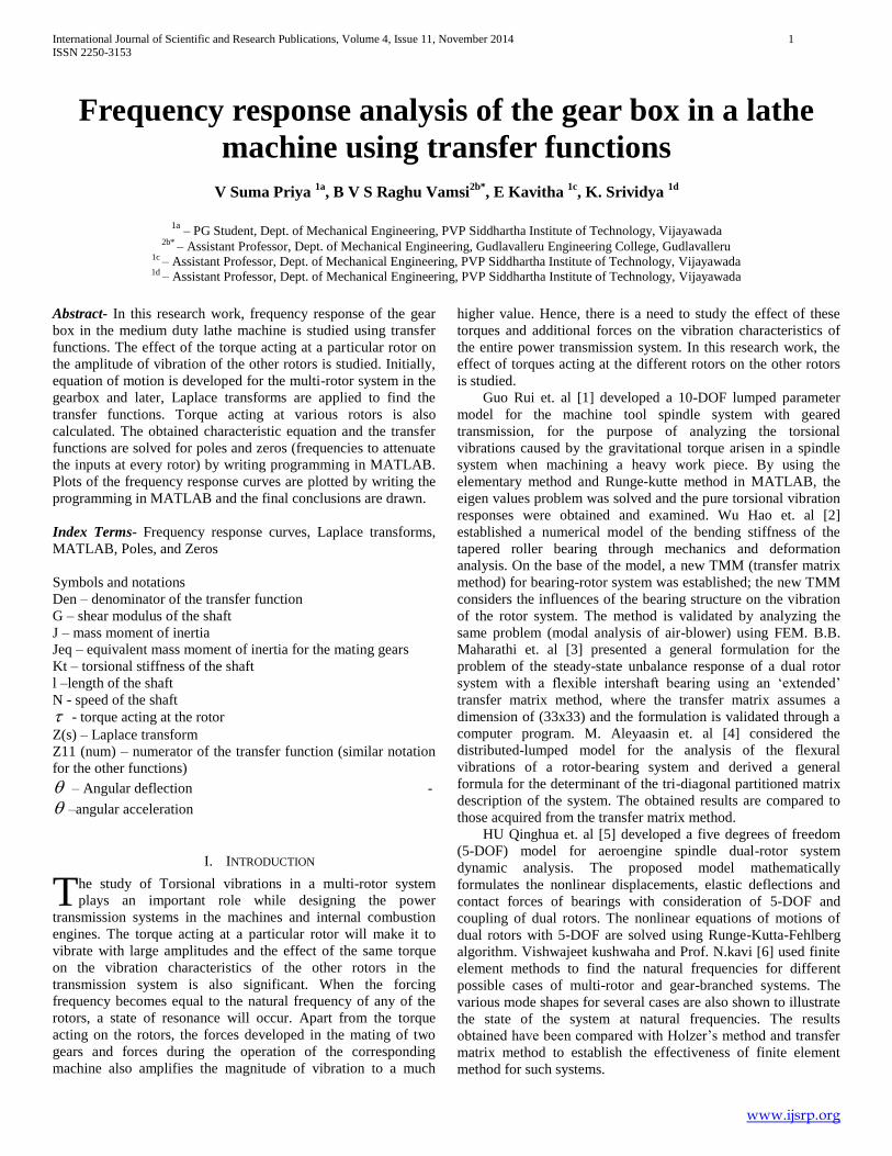
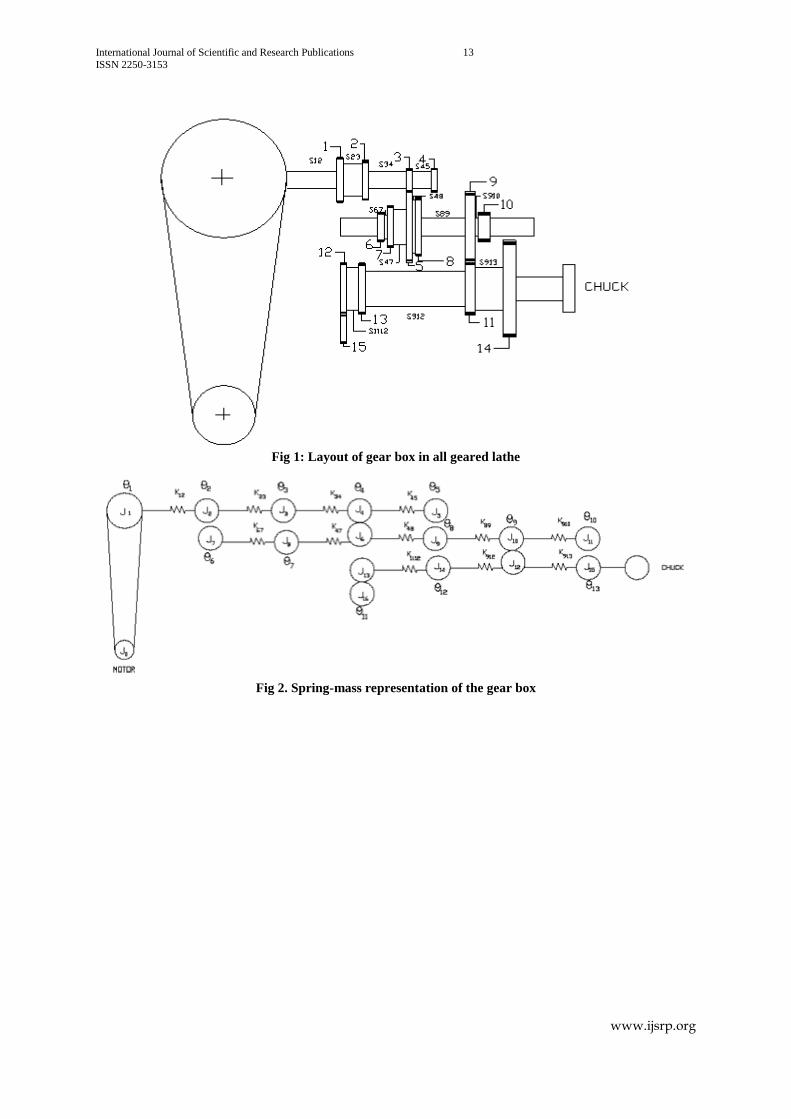
II. GEAR BOX ARRANGEMENT IN THE LATHE MACHINE
In this work, the gear box in a medium duty lathe machine is considered for the analysis. The frequency response of every
rotor to the torque acting at the self as well as other rotors is studied, to understand the vibration characteristics of a gear box
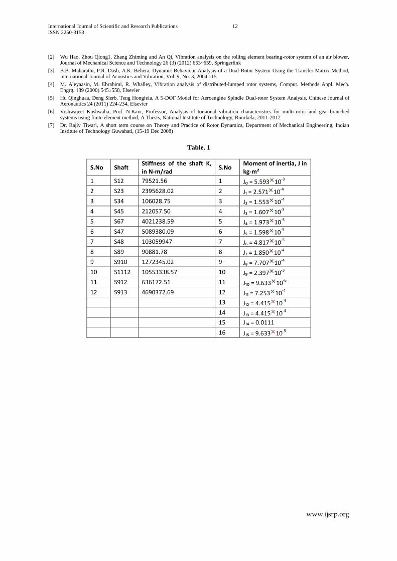
much better. The estimated details of the components in the gear box i.e. the stiffness of the shafts and moment of inertia of the
rotors (gears) are presented in the table 1. The arrangement of the various rotors in the gear box adopted in this study is presented
in the fig. 1. Stiffness of the shaft is calculated using the torsion equation:
tG GJ
J l R l (1)
III. MATHEMATICAL MODELING OF MULTI ROTOR SYSTEM
The spring-mass representation of the gear box is presented in fig. 2. Wherever two gears are mating, the equivalent mass
moment of inertia is calculated and it is considered to be as an equivalent rotor. The equation of motion can be derived by
Newton’s law as: ..
tJ K (2)
The equation of motion derived for the entire gear box is presented in as eq. (3) These equations are written in matrix form for
simplicity:
..
tJ K (4)
Where
J inertia matrix tk stiffness matrix
Torque matrix
Angular Acceleration matrix:
.. .. .. .. .. .. .. .. .. .. .. .. .. ..
1 2 3 4 5 6 7 8 9 10 11 12 13
T
Angular displacement matrix:
1 2 3 4 5 6 7 8 9 10 11 12 13
T
International Journal of Scientific and Research Publications 4
ISSN 2250-3153
www.ijsrp.org
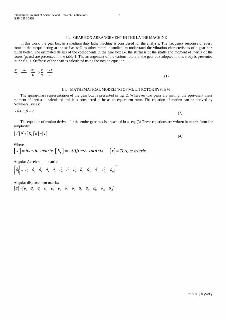
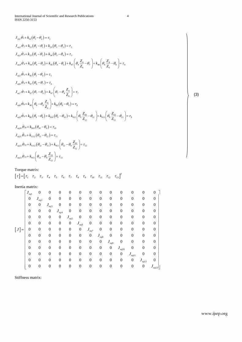
..
11 12 1 2 1
..
22 12 2 1 23 2 3 2
..
33 23 3 2 34 3 4 3
..4 4
44 34 4 3 45 4 5 47 4 7 48 4 8 4
6 6
..
55 45 5 4 5
..
66 67 6 7 6
..
77 67 7
eq
eq
eq
eq
eq
eq
eq
J k
J k k
J k k
Z ZJ k k k k
Z Z
J k
J k
J k
4
6 47 7 4 7
6
..4
88 48 8 4 89 8 9 8
6
..10 10
99 89 9 8 910 9 10 912 9 12 913 9 13 9
12 12
..
1010 910 10 9 10
..
1111 1112 11 12 11
..
12
eq
eq
eq
eq
eq
Zk
Z
ZJ k k
Z
Z ZJ k k k k
Z Z
J k
J k
J
1012 1112 12 11 912 12 9 12
12
..10
1313 913 13 9 13
12
eq
Zk k
Z
ZJ k
Z
Torque matrix:
1 2 3 4 5 6 7 8 9 10 11 12 13
T
Inertia matrix:
1
2
3
4
5
6
7
8
9
10
11
12
0 0 0 0 0 0 0 0 0 0 0 0
0 0 0 0 0 0 0 0 0 0 0 0
0 0 0 0 0 0 0 0 0 0 0 0
0 0 0 0 0 0 0 0 0 0 0 0
0 0 0 0 0 0 0 0 0 0 0 0
0 0 0 0 0 0 0 0 0 0 0 0
0 0 0 0 0 0 0 0 0 0 0 0
0 0 0 0 0 0 0 0 0 0 0 0
0 0 0 0 0 0 0 0 0 0 0 0
0 0 0 0 0 0 0 0 0 0 0 0
0 0 0 0 0 0 0 0 0 0 0 0
0 0 0 0 0 0 0 0 0 0 0 0
0 0 0
eq
eq
eq
eq
eq
eq
eq
eq
eq
eq
eq
eq
J
J
J
J
J
J
JJ
J
J
J
J
J
130 0 0 0 0 0 0 0 0 eqJ
Stiffness matrix:
(3)
International Journal of Scientific and Research Publications 5
ISSN 2250-3153
www.ijsrp.org
12 12
12 12 23 23
23 23 34 34
34 45
34 45 47 48447 48
6
45 45
67 67
447 67 47 67
6
448 48 89
6
0 0 0 0 0 0 0 0 0 0 0
0 0 0 0 0 0 0 0 0 0
0 0 0 0 0 0 0 0 0 0
0 0 0 0 0 0 0 0
0 0 0 0 0 0 0 0 0 0 0
0 0 0 0 0 0 0 0 0 0 0
0 0 0 0 0 0 0 0 0 0
0 0 0 0 0 0t
K K
K K K K
K K K K
K K
K K K KZK K
Z
K K
K K
ZK K K K
Z
K ZK K K
Z
89
89 910
89 910 912 91310912 913
12
910 910
1112 1112
10912 1112 1112 912
12
10913 913
12
0 0 0 0
0 0 0 0 0 0 0 0
0 0 0 0 0 0 0 0 0 0 0
0 0 0 0 0 0 0 0 0 0 0
0 0 0 0 0 0 0 0 0 0
0 0 0 0 0 0 0 0 0 0 0
K
K K
K K K KZK K
Z
K K
K K
ZK K K K
Z
ZK K
Z
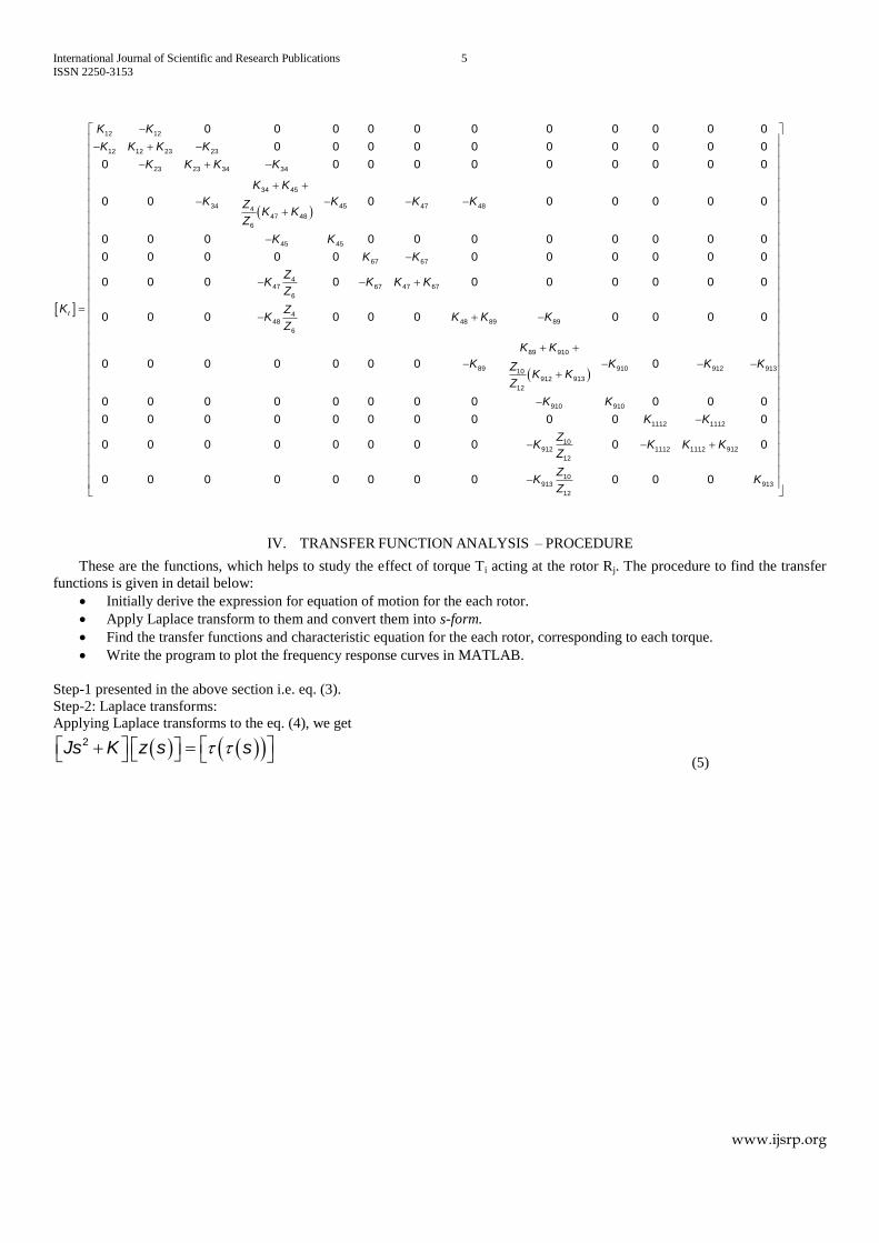
IV. TRANSFER FUNCTION ANALYSIS – PROCEDURE
These are the functions, which helps to study the effect of torque Ti acting at the rotor Rj. The procedure to find the transfer
functions is given in detail below:
Initially derive the expression for equation of motion for the each rotor.
Apply Laplace transform to them and convert them into s-form.
Find the transfer functions and characteristic equation for the each rotor, corresponding to each torque.
Write the program to plot the frequency response curves in MATLAB.
Step-1 presented in the above section i.e. eq. (3).
Step-2: Laplace transforms:
Applying Laplace transforms to the eq. (4), we get
2Js K z s s (5)
International Journal of Scientific and Research Publications 6
ISSN 2250-3153
www.ijsrp.org
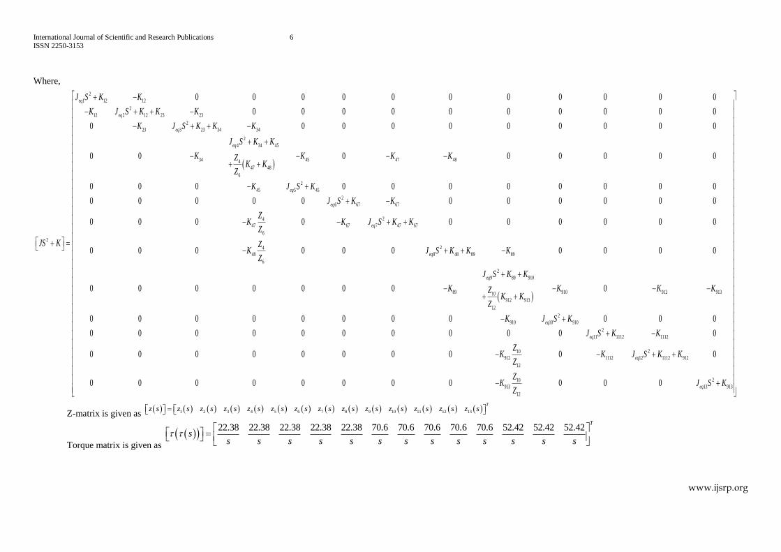
Where,
2
1 12 12
2
12 2 12 23 23
2
23 3 23 34 34
2
4 34 45
34 45 47 484
47 48
6
2
45 5 45
2
6 67 67
2
0 0 0 0 0 0 0 0 0 0 0
0 0 0 0 0 0 0 0 0 0
0 0 0 0 0 0 0 0 0 0
0 0 0 0 0 0 0 0
0 0 0 0 0 0 0 0 0 0 0
0 0 0 0 0 0 0 0 0 0 0
0
eq
eq
eq
eq
eq
eq
J S K K
K J S K K K
K J S K K K
J S K K
K K K KZK K
Z
K J S K
J S K K
JS K
24
47 67 7 47 67
6
24
48 8 48 89 89
6
2
9 89 910
89 910 912 91310
912 913
12
2
910 10 910
2
11 1112 1112
912
0 0 0 0 0 0 0 0 0
0 0 0 0 0 0 0 0 0 0
0 0 0 0 0 0 0 0
0 0 0 0 0 0 0 0 0 0 0
0 0 0 0 0 0 0 0 0 0 0
0 0 0 0 0 0 0 0
eq
eq
eq
eq
eq
ZK K J S K K
Z
ZK J S K K K
Z
J S K K
K K K KZK K
Z
K J S K
J S K K
K
210
1112 12 1112 912
12
210
913 13 913
12
0 0
0 0 0 0 0 0 0 0 0 0 0
eq
eq
ZK J S K K
Z
ZK J S K
Z
Z-matrix is given as 1 2 3 4 5 6 7 8 9 10 11 12 13
T
z s z s z s z s z s z s z s z s z s z s z s z s z s z s
Torque matrix is given as
22.38 22.38 22.38 22.38 22.38 70.6 70.6 70.6 70.6 70.6 52.42 52.42 52.42
T
ss s s s s s s s s s s s s
International Journal of Scientific and Research Publications 7
ISSN 2250-3153
www.ijsrp.org
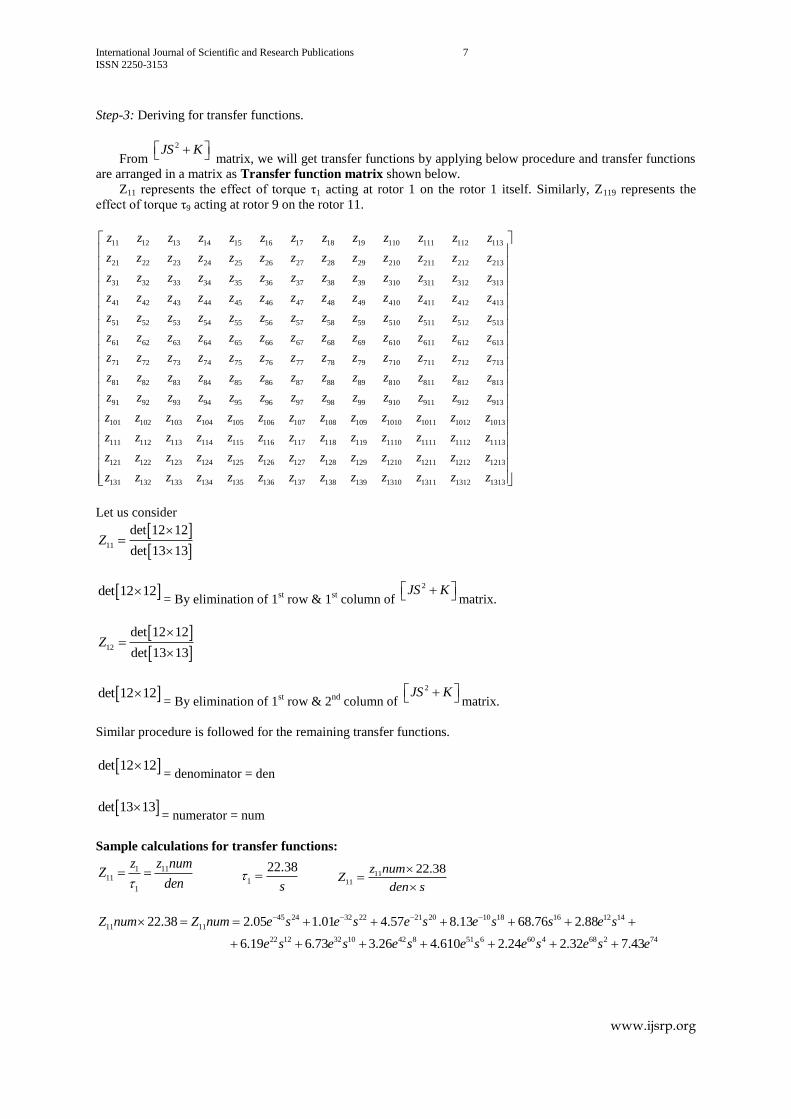
Step-3: Deriving for transfer functions.
From
2JS K matrix, we will get transfer functions by applying below procedure and transfer functions
are arranged in a matrix as Transfer function matrix shown below.
Z11 represents the effect of torque τ1 acting at rotor 1 on the rotor 1 itself. Similarly, Z119 represents the
effect of torque τ9 acting at rotor 9 on the rotor 11.
11 12 13 14 15 16 17 18 19 110 111 112 113
21 22 23 24 25 26 27 28 29 210 211 212 213
31 32 33 34 35 36 37 38 39 310 311 312 313
41 42 43 44 45 46 47 48 49 410 411 412 413
51 52 53 54 55 56 57 58 59
z z z z z z z z z z z z z
z z z z z z z z z z z z z
z z z z z z z z z z z z z
z z z z z z z z z z z z z
z z z z z z z z z z510 511 512 513
61 62 63 64 65 66 67 68 69 610 611 612 613
71 72 73 74 75 76 77 78 79 710 711 712 713
81 82 83 84 85 86 87 88 89 810 811 812 813
91 92 93 94 95 96 97 98 99 910 911 912 913
101 102 103
z z z
z z z z z z z z z z z z z
z z z z z z z z z z z z z
z z z z z z z z z z z z z
z z z z z z z z z z z z z
z z z z104 105 106 107 108 109 1010 1011 1012 1013
111 112 113 114 115 116 117 118 119 1110 1111 1112 1113
121 122 123 124 125 126 127 128 129 1210 1211 1212 1213
131 132 133 134 135 136 137 138 139 1310 131
z z z z z z z z z
z z z z z z z z z z z z z
z z z z z z z z z z z z z
z z z z z z z z z z z 1 1312 1313z z
Let us consider
11
det 12 12
det 13 13Z
det 12 12= By elimination of 1
st row & 1
st column of
2JS K matrix.
12
det 12 12
det 13 13Z
det 12 12= By elimination of 1
st row & 2
nd column of
2JS K matrix.
Similar procedure is followed for the remaining transfer functions.
det 12 12= denominator = den
det 13 13= numerator = num
Sample calculations for transfer functions:
1 11
11
1
z z numZ
den
1
22.38
s
11
11
22.38z numZ
den s
45 24 32 22 21 20 10 18 16 12 14
11 11
22 12 32 10 42 8 51 6 60 4 68 2 74
22.38 2.05 1.01 4.57 8.13 68.76 2.88
6.19 6.73 3.26 4.610 2.24 2.32 7.43
Z num Z num e s e s e s e s s e s
e s e s e s e s e s e s e
International Journal of Scientific and Research Publications 8
ISSN 2250-3153
www.ijsrp.org
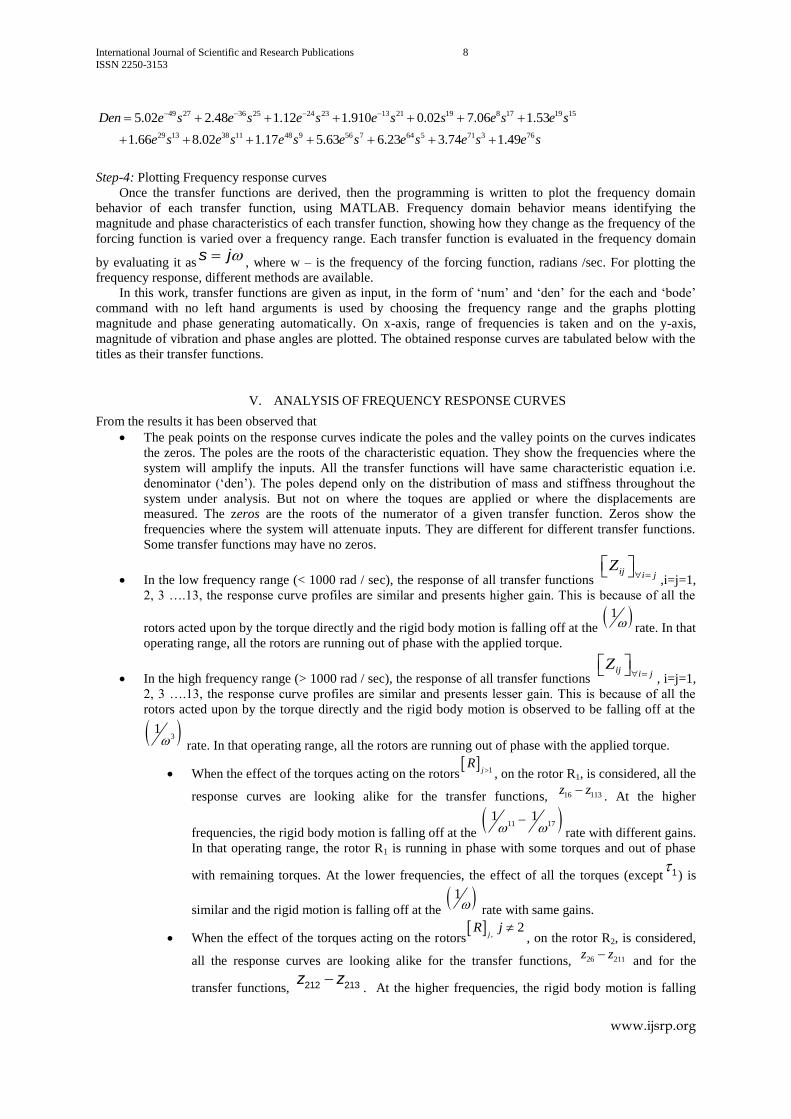
49 27 36 25 24 23 13 21 19 8 17 19 15
29 13 38 11 48 9 56 7 64 5 71 3 76
5.02 2.48 1.12 1.910 0.02 7.06 1.53
1.66 8.02 1.17 5.63 6.23 3.74 1.49
Den e s e s e s e s s e s e s
e s e s e s e s e s e s e s
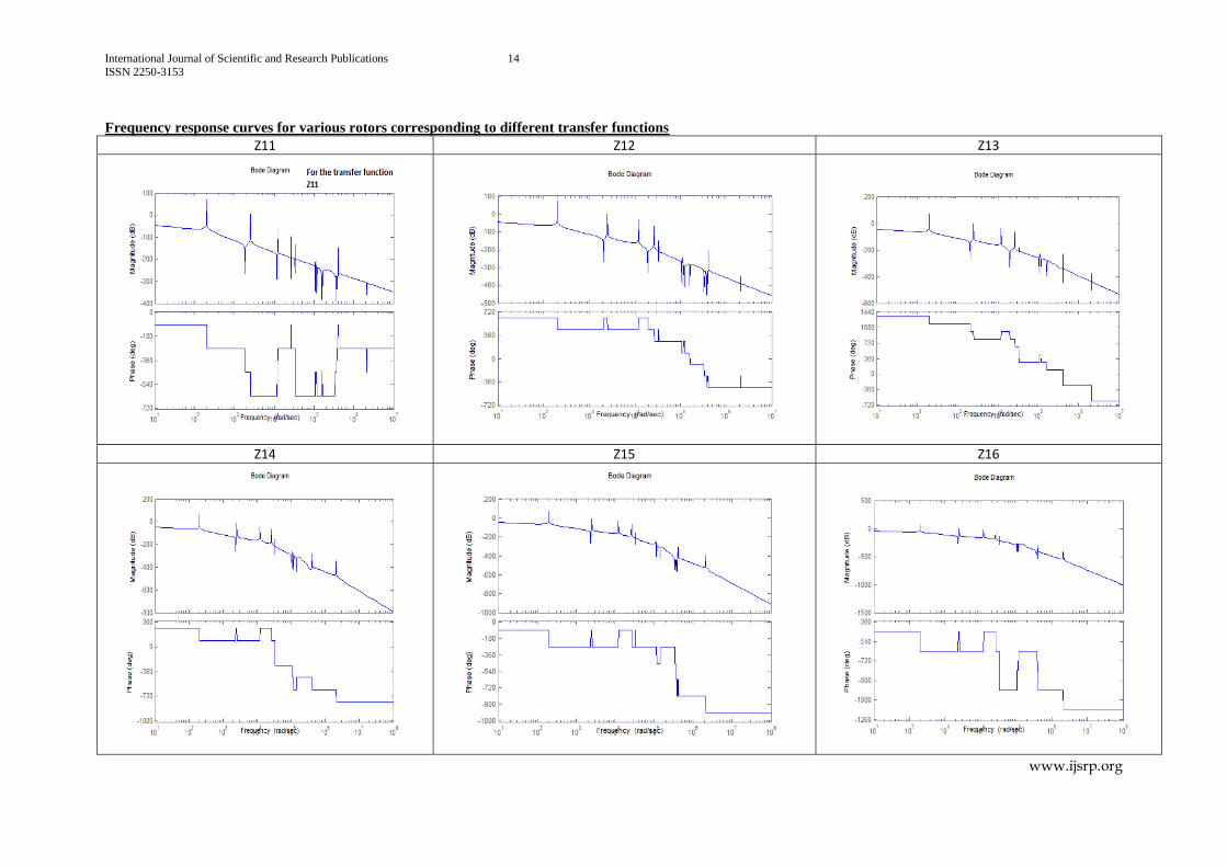
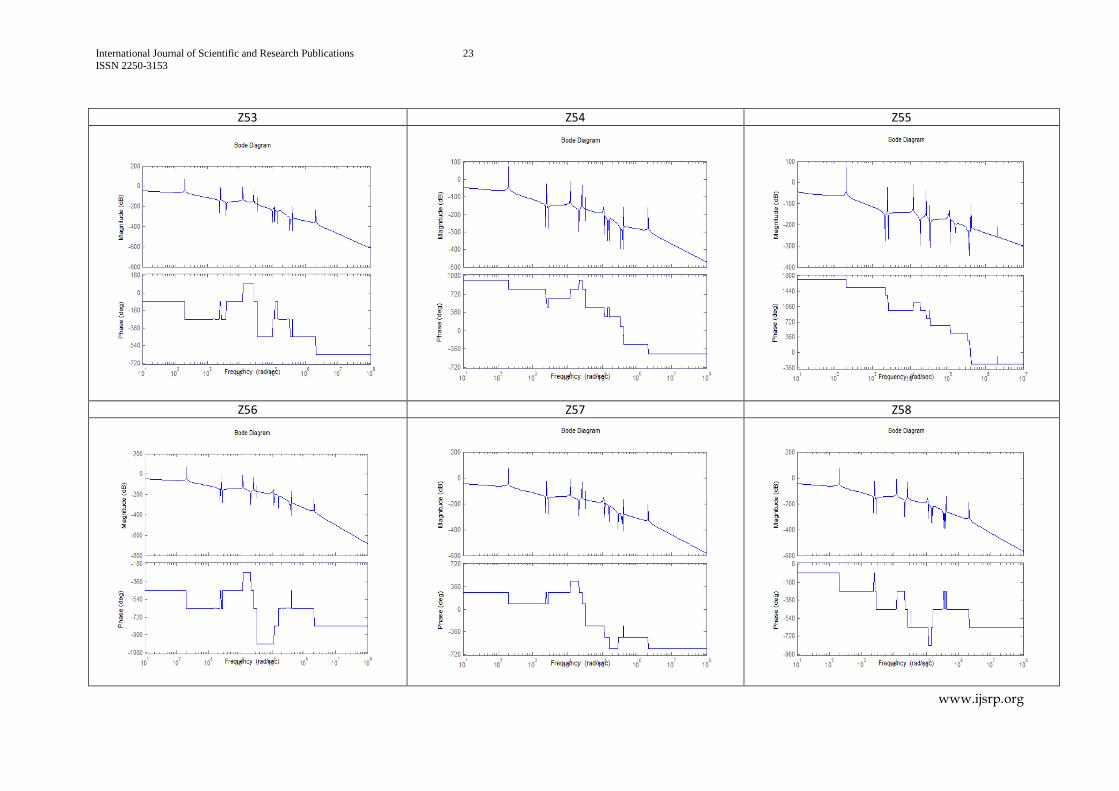
Step-4: Plotting Frequency response curves
Once the transfer functions are derived, then the programming is written to plot the frequency domain
behavior of each transfer function, using MATLAB. Frequency domain behavior means identifying the
magnitude and phase characteristics of each transfer function, showing how they change as the frequency of the
forcing function is varied over a frequency range. Each transfer function is evaluated in the frequency domain
by evaluating it ass j
, where w – is the frequency of the forcing function, radians /sec. For plotting the
frequency response, different methods are available.
In this work, transfer functions are given as input, in the form of ‘num’ and ‘den’ for the each and ‘bode’
command with no left hand arguments is used by choosing the frequency range and the graphs plotting
magnitude and phase generating automatically. On x-axis, range of frequencies is taken and on the y-axis,
magnitude of vibration and phase angles are plotted. The obtained response curves are tabulated below with the
titles as their transfer functions.
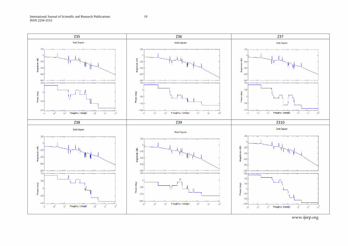
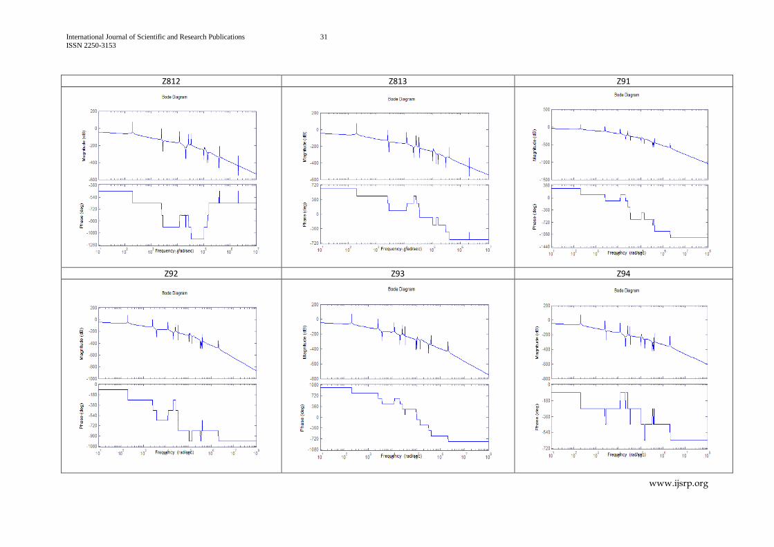
V. ANALYSIS OF FREQUENCY RESPONSE CURVES
From the results it has been observed that
The peak points on the response curves indicate the poles and the valley points on the curves indicates
the zeros. The poles are the roots of the characteristic equation. They show the frequencies where the
system will amplify the inputs. All the transfer functions will have same characteristic equation i.e.
denominator (‘den’). The poles depend only on the distribution of mass and stiffness throughout the
system under analysis. But not on where the toques are applied or where the displacements are
measured. The zeros are the roots of the numerator of a given transfer function. Zeros show the
frequencies where the system will attenuate inputs. They are different for different transfer functions.
Some transfer functions may have no zeros.
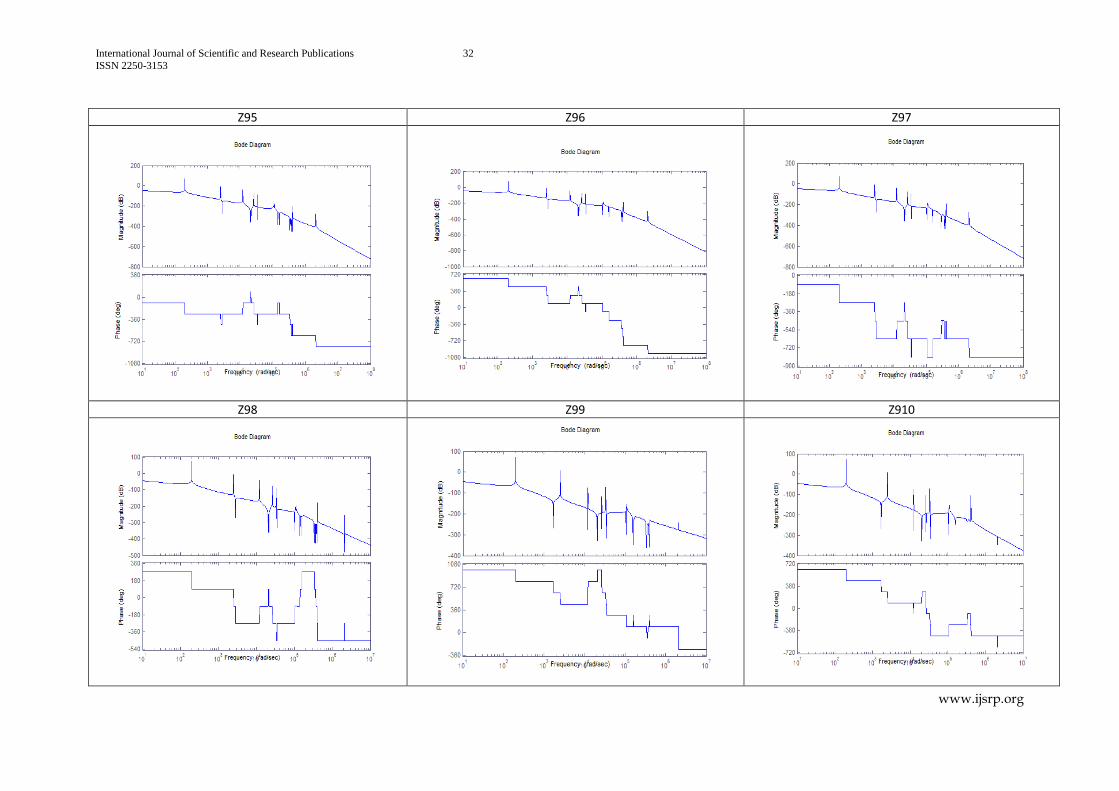
In the low frequency range (< 1000 rad / sec), the response of all transfer functions ij i j
Z
,i=j=1,
2, 3 ….13, the response curve profiles are similar and presents higher gain. This is because of all the
rotors acted upon by the torque directly and the rigid body motion is falling off at the 1 rate. In that
operating range, all the rotors are running out of phase with the applied torque.
In the high frequency range (> 1000 rad / sec), the response of all transfer functions ij i j
Z
, i=j=1,
2, 3 ….13, the response curve profiles are similar and presents lesser gain. This is because of all the
rotors acted upon by the torque directly and the rigid body motion is observed to be falling off at the
31 rate. In that operating range, all the rotors are running out of phase with the applied torque.
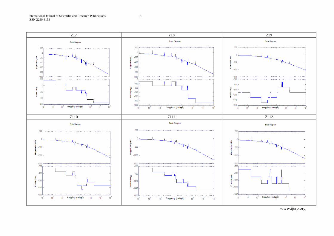
When the effect of the torques acting on the rotors
1jR
, on the rotor R1, is considered, all the
response curves are looking alike for the transfer functions, 16 113z z. At the higher
frequencies, the rigid body motion is falling off at the 11 17
1 1
rate with different gains.
In that operating range, the rotor R1 is running in phase with some torques and out of phase
with remaining torques. At the lower frequencies, the effect of all the torques (except 1 ) is
similar and the rigid motion is falling off at the 1 rate with same gains.
When the effect of the torques acting on the rotors
,2
jR j
, on the rotor R2, is considered,
all the response curves are looking alike for the transfer functions, 26 211z z and for the
transfer functions, 212 213z z
. At the higher frequencies, the rigid body motion is falling
International Journal of Scientific and Research Publications 9
ISSN 2250-3153
www.ijsrp.org
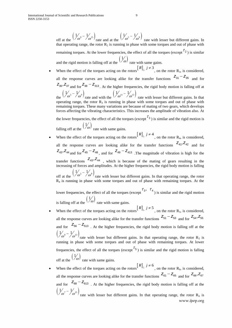
off at the 9 15
1 1
rate and at the
5 91 1
rate with lesser but different gains. In
that operating range, the rotor R2 is running in phase with some torques and out of phase with
remaining torques. At the lower frequencies, the effect of all the torques (except 2 ) is similar
and the rigid motion is falling off at the 1 rate with same gains.
When the effect of the torques acting on the rotors
,3
jR j
, on the rotor R3, is considered,
all the response curves are looking alike for the transfer functions 31 35z z and for
36 37,z zand for 38 313z z
. At the higher frequencies, the rigid body motion is falling off at
the 5 9
1 1
rate and with the
11 131 1
rate with lesser but different gains. In that
operating range, the rotor R3 is running in phase with some torques and out of phase with
remaining torques. These many variations are because of mating of two gears, which develops
forces affecting the vibrating characteristics. This increases the amplitude of vibration also. At
the lower frequencies, the effect of all the torques (except 3 ) is similar and the rigid motion is
falling off at the 1 rate with same gains.
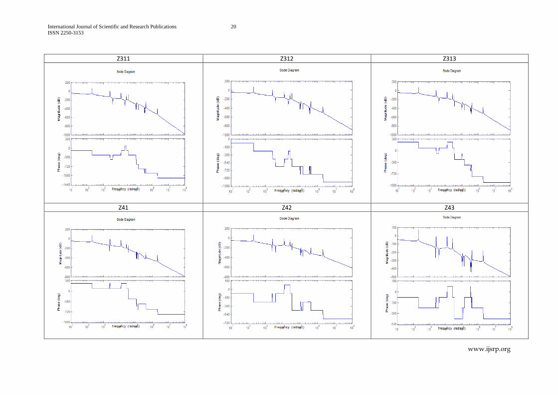
When the effect of the torques acting on the rotors
,4
jR j
, on the rotor R4, is considered,
all the response curves are looking alike for the transfer functions 41 42,z z and for
43 44,z zand for 45 48z z
, and for 49 413z z .The magnitude of vibration is high for the
transfer functions 43 44,z z , which is because of the mating of gears resulting in the
increasing of forces and amplitudes. At the higher frequencies, the rigid body motion is falling
off at the 5 9
1 1
rate with lesser but different gains. In that operating range, the rotor
R4 is running in phase with some torques and out of phase with remaining torques. At the
lower frequencies, the effect of all the torques (except3 4,
) is similar and the rigid motion
is falling off at the 1 rate with same gains.
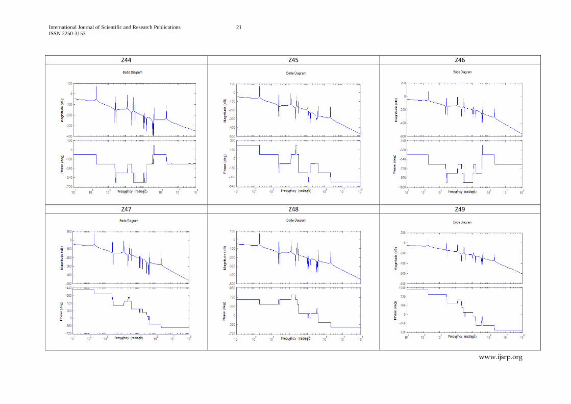
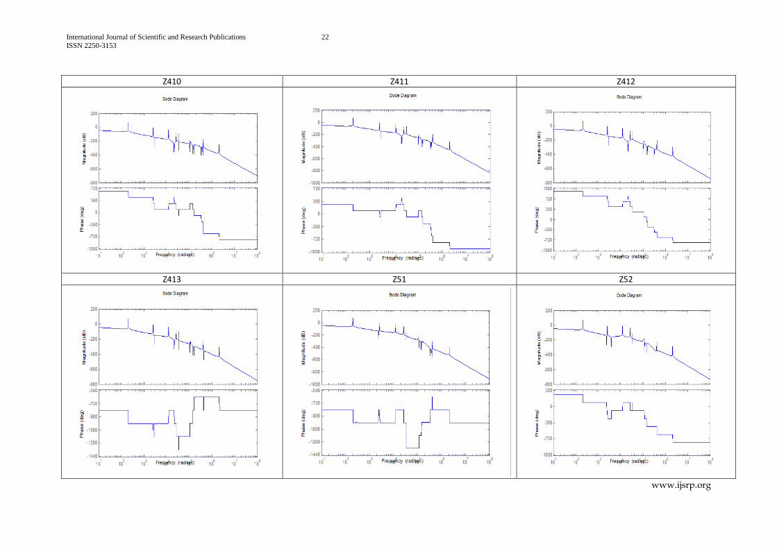
When the effect of the torques acting on the rotors
,5
jR j
, on the rotor R5, is considered,
all the response curves are looking alike for the transfer functions 51 53z z and for 54 55,z z
and for 56 513z z . At the higher frequencies, the rigid body motion is falling off at the
9 131 1
rate with lesser but different gains. In that operating range, the rotor R5 is
running in phase with some torques and out of phase with remaining torques. At lower
frequencies, the effect of all the torques (except 5 ) is similar and the rigid motion is falling
off at the 1 rate with same gains.
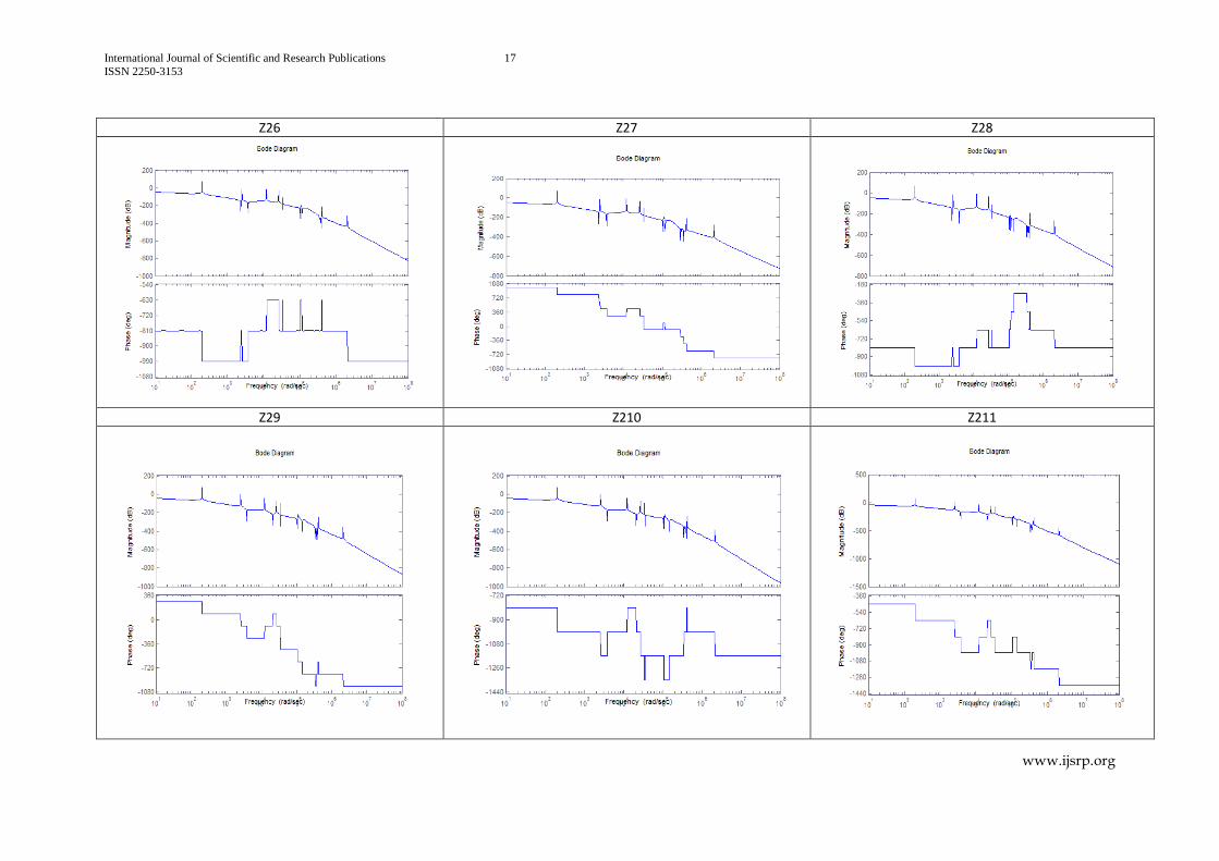
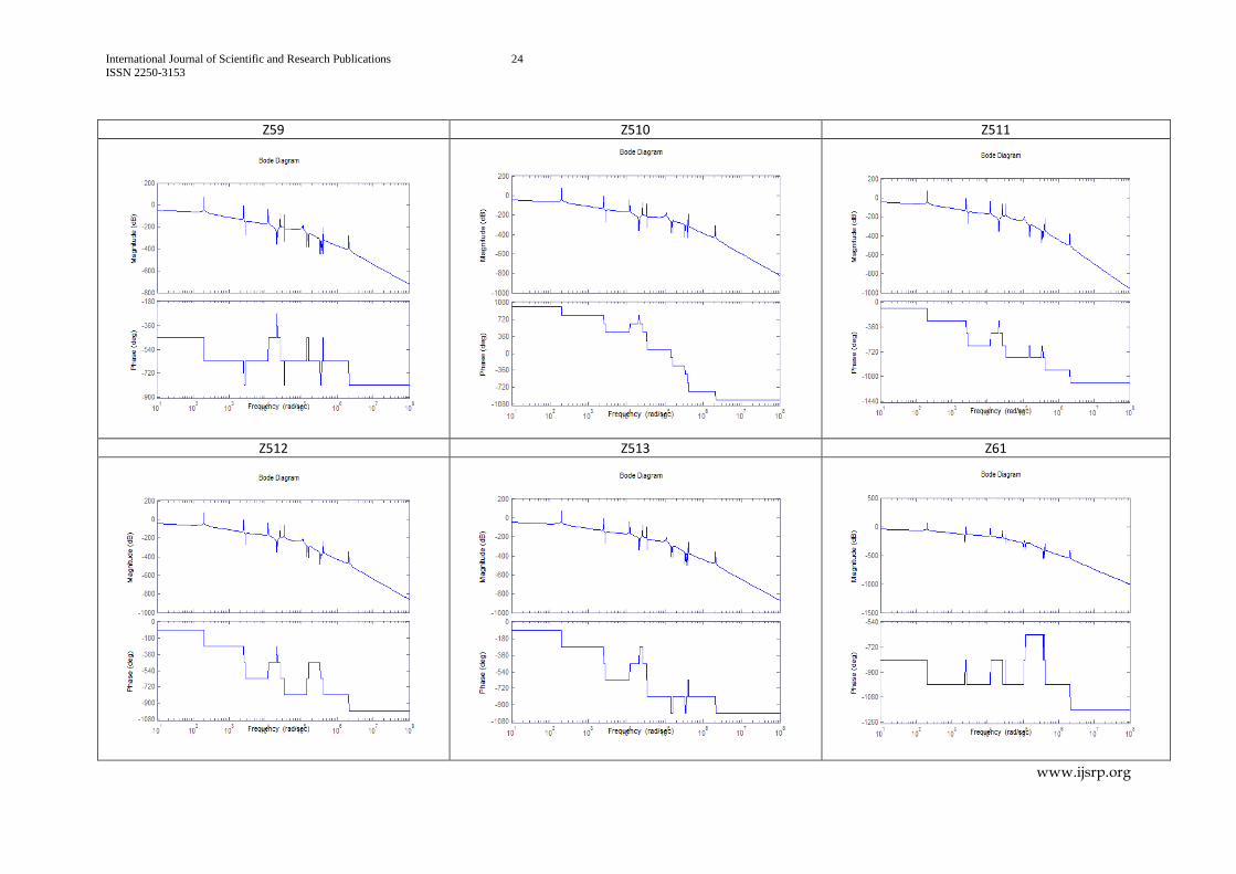
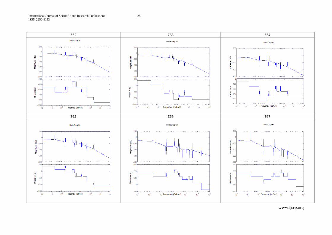
When the effect of the torques acting on the rotors
,6
jR j
, on the rotor R6, is considered,
all the response curves are looking alike for the transfer functions 61 65z z and for 66 67,z z
and for 68 613z z . At the higher frequencies, the rigid body motion is falling off at the
7 151 1
rate with lesser but different gains. In that operating range, the rotor R6 is
International Journal of Scientific and Research Publications 10
ISSN 2250-3153
www.ijsrp.org
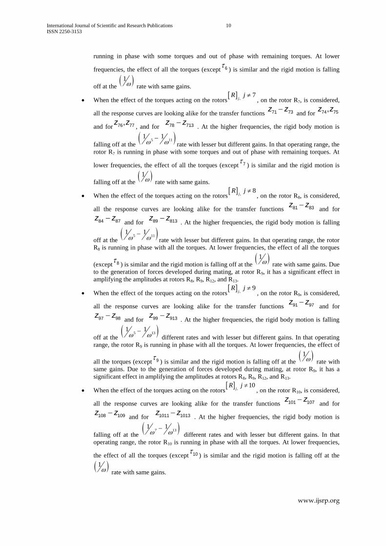
running in phase with some torques and out of phase with remaining torques. At lower
frequencies, the effect of all the torques (except 6 ) is similar and the rigid motion is falling
off at the 1 rate with same gains.
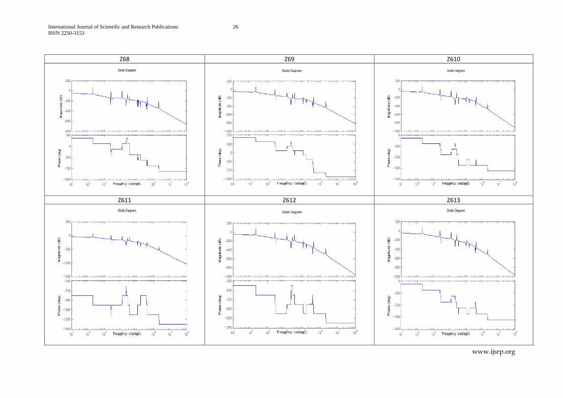
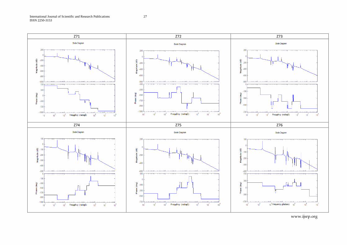
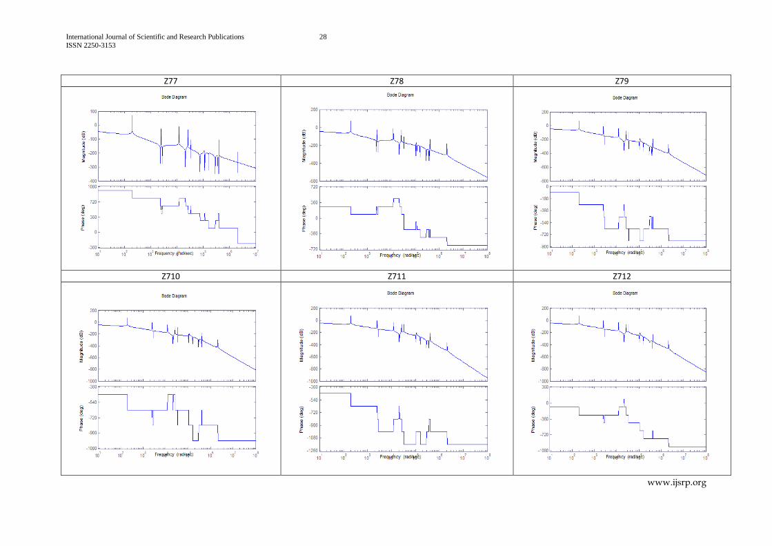
When the effect of the torques acting on the rotors
,7
jR j
, on the rotor R7, is considered,
all the response curves are looking alike for the transfer functions 71 73z z and for 74 75,z z
and for 76 77,z z, and for 78 713z z
. At the higher frequencies, the rigid body motion is
falling off at the 5 11
1 1
rate with lesser but different gains. In that operating range, the
rotor R7 is running in phase with some torques and out of phase with remaining torques. At
lower frequencies, the effect of all the torques (except 7 ) is similar and the rigid motion is
falling off at the 1 rate with same gains.
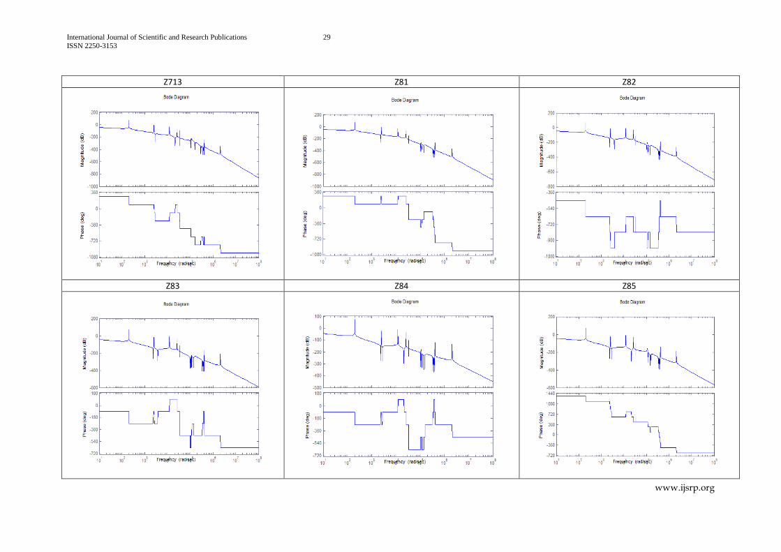
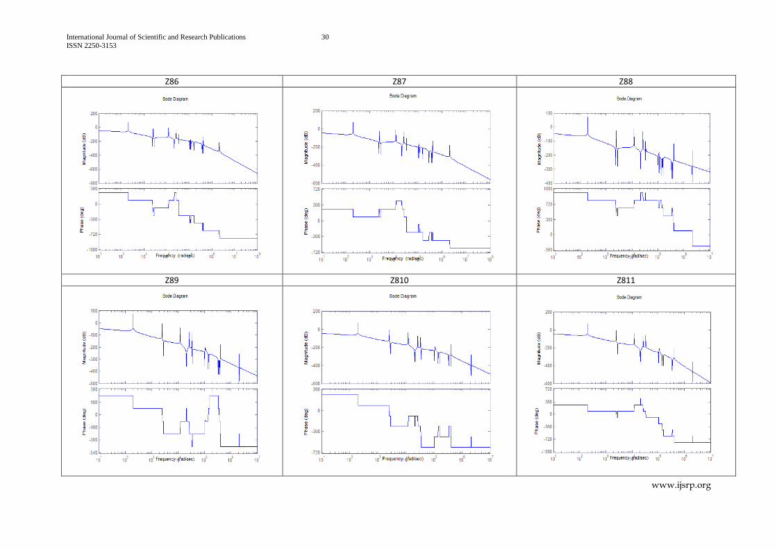
When the effect of the torques acting on the rotors
,8
jR j
, on the rotor R8, is considered,
all the response curves are looking alike for the transfer functions 81 83z z and for
84 87z z and for 89 813z z
. At the higher frequencies, the rigid body motion is falling
off at the 5 11
1 1
rate with lesser but different gains. In that operating range, the rotor
R8 is running in phase with all the torques. At lower frequencies, the effect of all the torques
(except 8 ) is similar and the rigid motion is falling off at the 1 rate with same gains. Due
to the generation of forces developed during mating, at rotor R9, it has a significant effect in
amplifying the amplitudes at rotors R8, R9, R12, and R13.
When the effect of the torques acting on the rotors
,9
jR j
, on the rotor R9, is considered,
all the response curves are looking alike for the transfer functions 91 97z z and for
97 98z z and for 99 913z z
. At the higher frequencies, the rigid body motion is falling
off at the 5 13
1 1
different rates and with lesser but different gains. In that operating
range, the rotor R9 is running in phase with all the torques. At lower frequencies, the effect of
all the torques (except 9 ) is similar and the rigid motion is falling off at the 1 rate with
same gains. Due to the generation of forces developed during mating, at rotor R9, it has a
significant effect in amplifying the amplitudes at rotors R8, R9, R12, and R13.
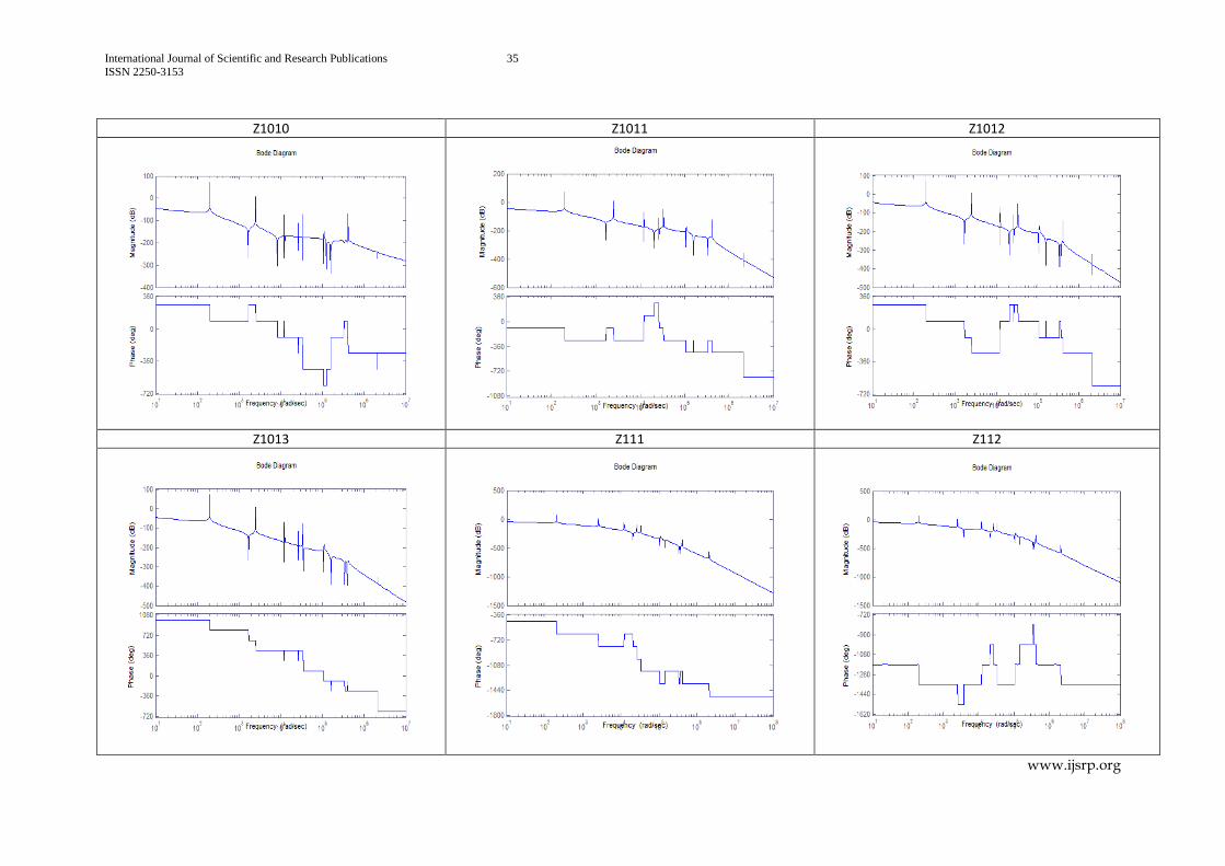
When the effect of the torques acting on the rotors
,10
jR j
, on the rotor R10, is considered,
all the response curves are looking alike for the transfer functions 101 107z z and for
108 109z z and for 1011 1013z z
. At the higher frequencies, the rigid body motion is
falling off at the 7 13
1 1
different rates and with lesser but different gains. In that
operating range, the rotor R10 is running in phase with all the torques. At lower frequencies,
the effect of all the torques (except 10) is similar and the rigid motion is falling off at the
1 rate with same gains.
International Journal of Scientific and Research Publications 11
ISSN 2250-3153
www.ijsrp.org
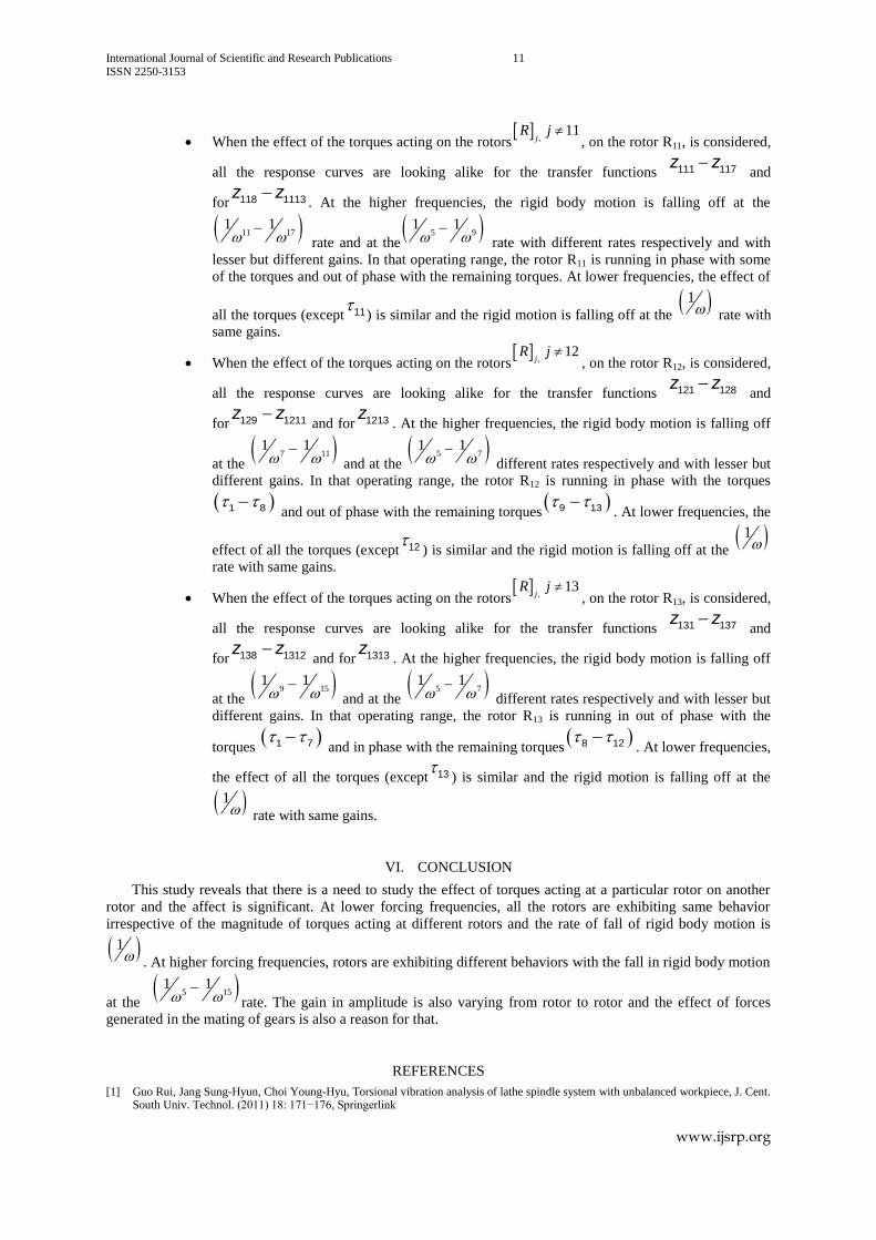
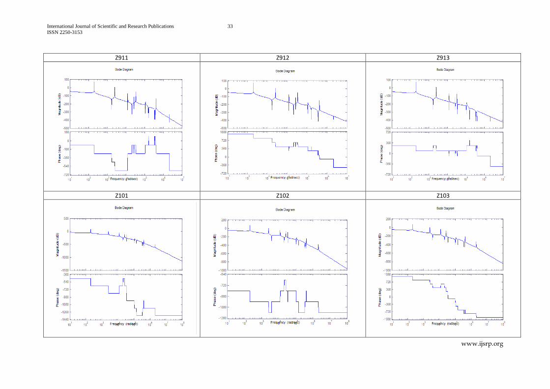
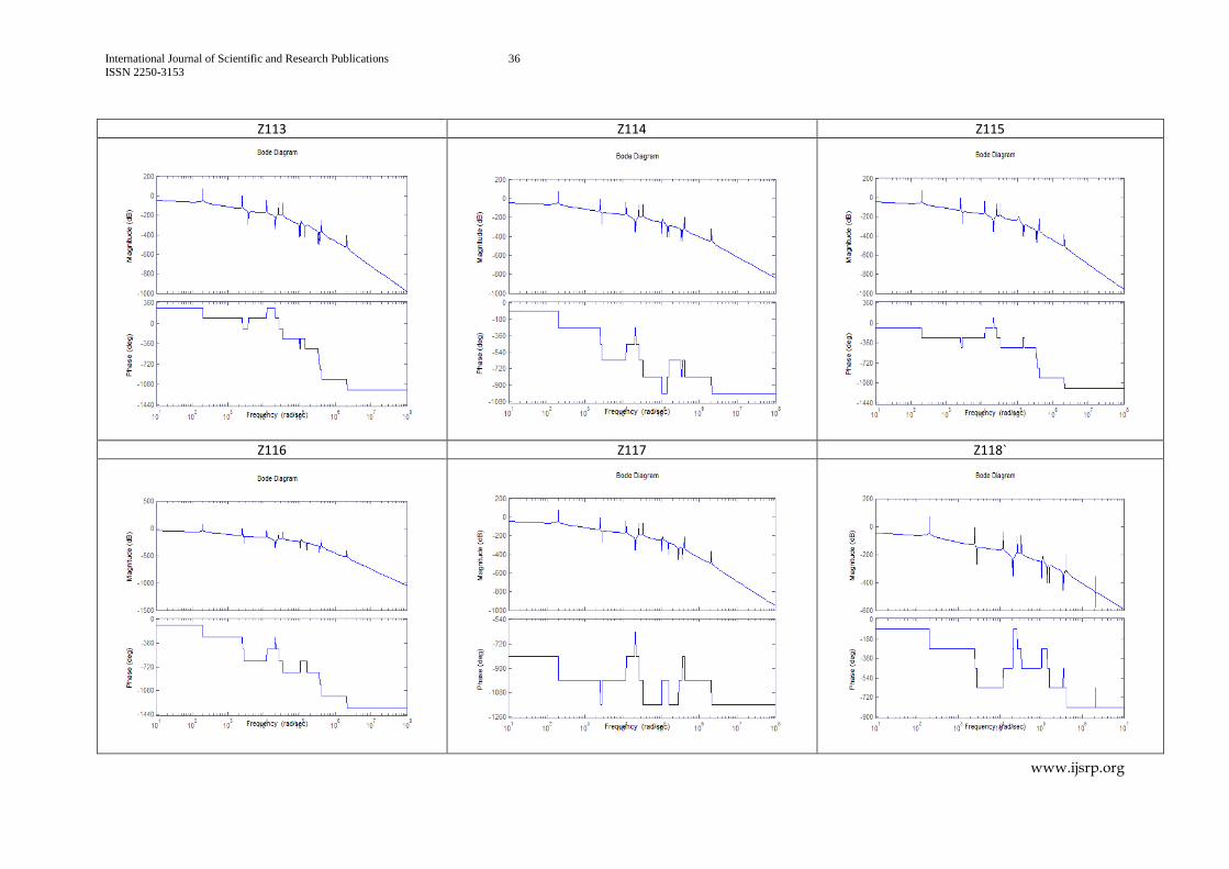
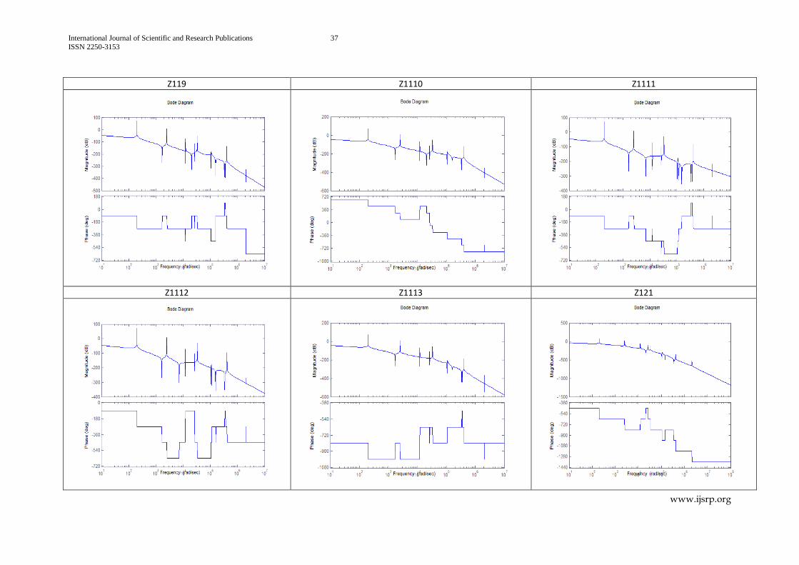
When the effect of the torques acting on the rotors
,11
jR j
, on the rotor R11, is considered,
all the response curves are looking alike for the transfer functions 111 117z z and
for 118 1113z z. At the higher frequencies, the rigid body motion is falling off at the
11 171 1
rate and at the
5 91 1
rate with different rates respectively and with
lesser but different gains. In that operating range, the rotor R11 is running in phase with some
of the torques and out of phase with the remaining torques. At lower frequencies, the effect of
all the torques (except 11) is similar and the rigid motion is falling off at the
1 rate with
same gains.
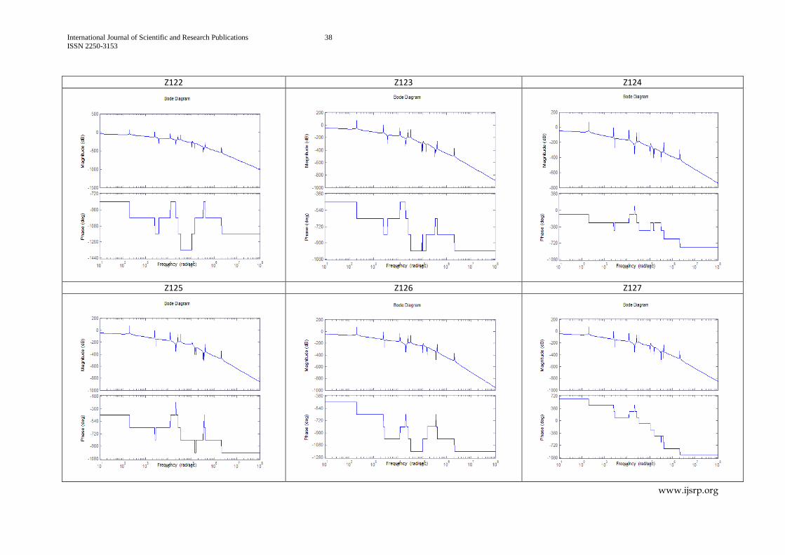
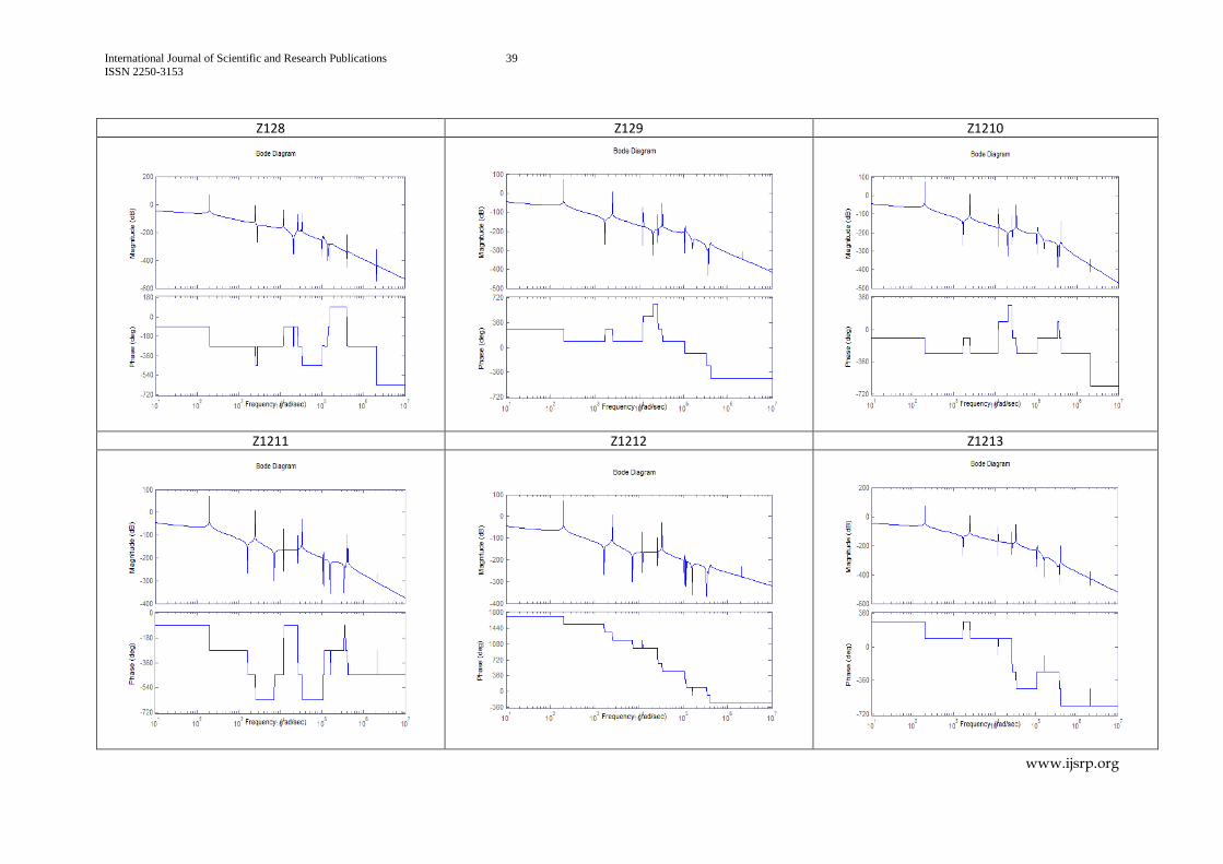
When the effect of the torques acting on the rotors
,12
jR j
, on the rotor R12, is considered,
all the response curves are looking alike for the transfer functions 121 128z z and
for 129 1211z z and for 1213z
. At the higher frequencies, the rigid body motion is falling off
at the 7 11
1 1
and at the
5 71 1
different rates respectively and with lesser but
different gains. In that operating range, the rotor R12 is running in phase with the torques
1 8 and out of phase with the remaining torques
9 13 . At lower frequencies, the
effect of all the torques (except 12) is similar and the rigid motion is falling off at the
1
rate with same gains.
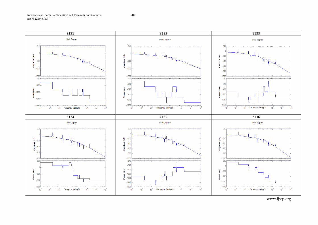
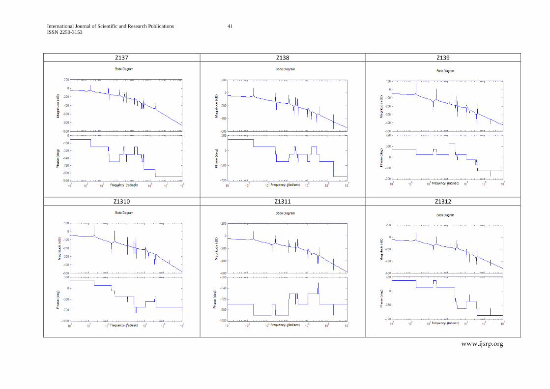
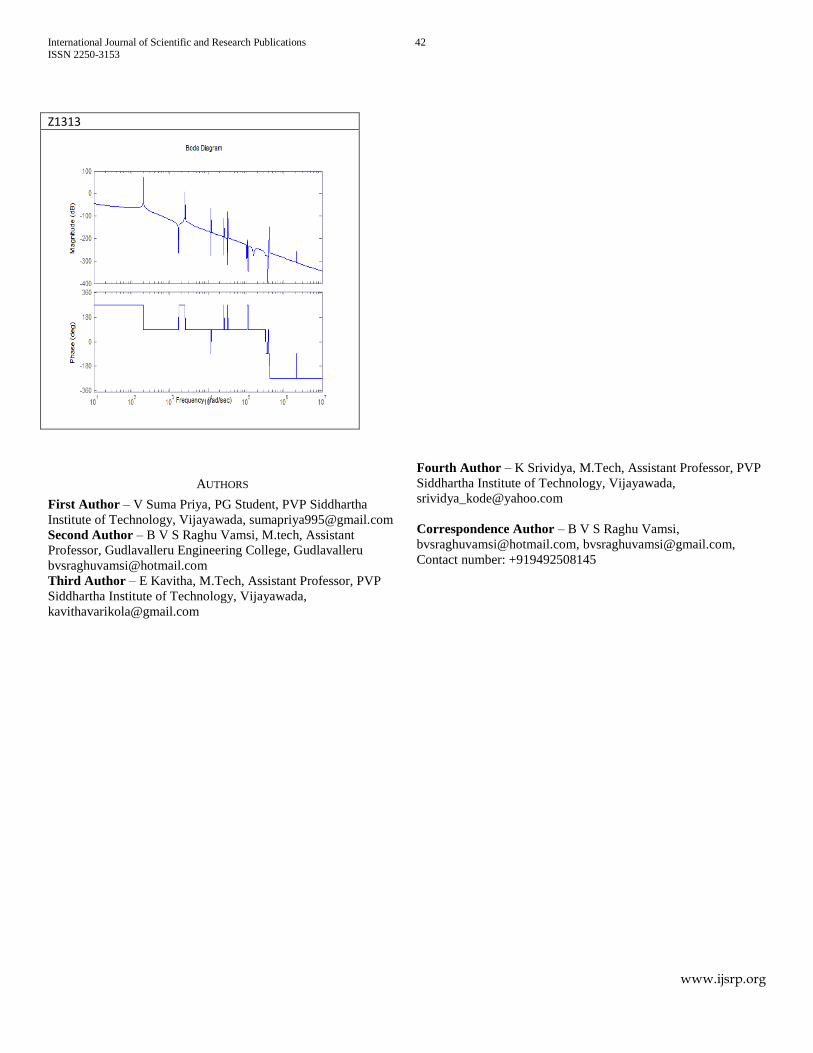
When the effect of the torques acting on the rotors
,13
jR j
, on the rotor R13, is considered,
all the response curves are looking alike for the transfer functions 131 137z z and
for 138 1312z z and for 1313z
. At the higher frequencies, the rigid body motion is falling off
at the 9 15
1 1
and at the
5 71 1
different rates respectively and with lesser but
different gains. In that operating range, the rotor R13 is running in out of phase with the
torques 1 7
and in phase with the remaining torques 8 12
. At lower frequencies,
the effect of all the torques (except 13) is similar and the rigid motion is falling off at the
1 rate with same gains.
VI. CONCLUSION
This study reveals that there is a need to study the effect of torques acting at a particular rotor on another
rotor and the affect is significant. At lower forcing frequencies, all the rotors are exhibiting same behavior
irrespective of the magnitude of torques acting at different rotors and the rate of fall of rigid body motion is
1 . At higher forcing frequencies, rotors are exhibiting different behaviors with the fall in rigid body motion
at the 5 15
1 1
rate. The gain in amplitude is also varying from rotor to rotor and the effect of forces
generated in the mating of gears is also a reason for that.
REFERENCES
[1] Guo Rui, Jang Sung-Hyun, Choi Young-Hyu, Torsional vibration analysis of lathe spindle system with unbalanced workpiece, J. Cent. South Univ. Technol. (2011) 18: 171−176, Springerlink
International Journal of Scientific and Research Publications 12
ISSN 2250-3153
www.ijsrp.org
[2] Wu Hao, Zhou Qiong1, Zhang Zhiming and An Qi, Vibration analysis on the rolling element bearing-rotor system of an air blower, Journal of Mechanical Science and Technology 26 (3) (2012) 653~659, Springerlink
[3] B.B. Maharathi, P.R. Dash, A.K. Behera, Dynamic Behaviour Analysis of a Dual-Rotor System Using the Transfer Matrix Method, International Journal of Acoustics and Vibration, Vol. 9, No. 3, 2004 115
[4] M. Aleyaasin, M. Ebrahimi, R. Whalley, Vibration analysis of distributed-lumped rotor systems, Comput. Methods Appl. Mech. Engrg. 189 (2000) 545±558, Elsevier
[5] Hu Qinghuaa, Deng Sierb, Teng Hongfeia, A 5-DOF Model for Aeroengine Spindle Dual-rotor System Analysis, Chinese Journal of Aeronautics 24 (2011) 224-234, Elsevier
[6] Vishwajeet Kushwaha, Prof. N.Kavi, Professor, Analysis of torsional vibration characteristics for multi-rotor and gear-branched systems using finite element method, A Thesis, National Institute of Technology, Rourkela, 2011-2012
[7] Dr. Rajiv Tiwari, A short term course on Theory and Practice of Rotor Dynamics, Department of Mechanical Engineering, Indian Institute of Technology Guwahati, (15-19 Dec 2008)
Table. 1
S.No Shaft Stiffness of the shaft K, in N-m/rad
S.No Moment of inertia, J in kg-m²
1 S12 79521.56 1 J₀ = 5.593 10-3
2 S23 2395628.02 2 J₁ = 2.571 10-4
3 S34 106028.75 3 J₂ = 1.553 10-4
4 S45 212057.50 4 J₃ = 1.607 10-5
5 S67 4021238.59 5 J₄ = 1.973 10-5
6 S47 5089380.09 6 J₅ = 1.598 10-5
7 S48 103059947 7 J₆ = 4.817 10-5
8 S89 90881.78 8 J₇ = 1.850 10-4
9 S910 1272345.02 9 J₈ = 7.707 10-4
10 S1112 10553338.57 10 J₉ = 2.397 10-3
11 S912 636172.51 11 J₁₀ = 9.633 10-6
12 S913 4690372.69 12 J₁₁ = 7.253 10-4
13 J₁₂ = 4.415 10-4
14 J₁₃ = 4.415 10-4
15 J₁₄ = 0.0111
16 J₁₅ = 9.633 10-5
International Journal of Scientific and Research Publications 13
ISSN 2250-3153
www.ijsrp.org
Fig 1: Layout of gear box in all geared lathe
Fig 2. Spring-mass representation of the gear box
International Journal of Scientific and Research Publications 14
ISSN 2250-3153
www.ijsrp.org
Frequency response curves for various rotors corresponding to different transfer functions
Z11 Z12 Z13
Z14 Z15 Z16
International Journal of Scientific and Research Publications 15
ISSN 2250-3153
www.ijsrp.org
Z17 Z18 Z19
Z110 Z111 Z112

International Journal of Scientific and Research Publications 16
ISSN 2250-3153
www.ijsrp.org
Z113 Z21 Z22
Z23 Z24 Z25
International Journal of Scientific and Research Publications 17
ISSN 2250-3153
www.ijsrp.org
Z26 Z27 Z28
Z29 Z210 Z211

International Journal of Scientific and Research Publications 18
ISSN 2250-3153
www.ijsrp.org
Z212 Z213 Z31
Z32 Z33 Z34
International Journal of Scientific and Research Publications 19
ISSN 2250-3153
www.ijsrp.org
Z35 Z36 Z37
Z38 Z39 Z310
International Journal of Scientific and Research Publications 20
ISSN 2250-3153
www.ijsrp.org
Z311 Z312 Z313
Z41 Z42 Z43
International Journal of Scientific and Research Publications 21
ISSN 2250-3153
www.ijsrp.org
Z44 Z45 Z46
Z47 Z48 Z49
International Journal of Scientific and Research Publications 22
ISSN 2250-3153
www.ijsrp.org
Z410 Z411 Z412
Z413 Z51 Z52
International Journal of Scientific and Research Publications 23
ISSN 2250-3153
www.ijsrp.org
Z53 Z54 Z55
Z56 Z57 Z58
International Journal of Scientific and Research Publications 24
ISSN 2250-3153
www.ijsrp.org
Z59 Z510 Z511
Z512 Z513 Z61
International Journal of Scientific and Research Publications 25
ISSN 2250-3153
www.ijsrp.org
Z62 Z63 Z64
Z65 Z66 Z67
International Journal of Scientific and Research Publications 26
ISSN 2250-3153
www.ijsrp.org
Z68 Z69 Z610
Z611 Z612 Z613
International Journal of Scientific and Research Publications 27
ISSN 2250-3153
www.ijsrp.org
Z71 Z72 Z73
Z74 Z75 Z76
International Journal of Scientific and Research Publications 28
ISSN 2250-3153
www.ijsrp.org
Z77 Z78 Z79
Z710 Z711 Z712
International Journal of Scientific and Research Publications 29
ISSN 2250-3153
www.ijsrp.org
Z713 Z81 Z82
Z83 Z84 Z85
International Journal of Scientific and Research Publications 30
ISSN 2250-3153
www.ijsrp.org
Z86 Z87 Z88
Z89 Z810 Z811
International Journal of Scientific and Research Publications 31
ISSN 2250-3153
www.ijsrp.org
Z812 Z813 Z91
Z92 Z93 Z94
International Journal of Scientific and Research Publications 32
ISSN 2250-3153
www.ijsrp.org
Z95 Z96 Z97
Z98 Z99 Z910
International Journal of Scientific and Research Publications 33
ISSN 2250-3153
www.ijsrp.org
Z911 Z912 Z913
Z101 Z102 Z103

International Journal of Scientific and Research Publications 34
ISSN 2250-3153
www.ijsrp.org
Z104 Z105 Z106
Z107 Z108 Z109
International Journal of Scientific and Research Publications 35
ISSN 2250-3153
www.ijsrp.org
Z1010 Z1011 Z1012
Z1013 Z111 Z112
International Journal of Scientific and Research Publications 36
ISSN 2250-3153
www.ijsrp.org
Z113 Z114 Z115
Z116 Z117 Z118`
International Journal of Scientific and Research Publications 37
ISSN 2250-3153
www.ijsrp.org
Z119 Z1110 Z1111
Z1112 Z1113 Z121
International Journal of Scientific and Research Publications 38
ISSN 2250-3153
www.ijsrp.org
Z122 Z123 Z124
Z125 Z126 Z127
International Journal of Scientific and Research Publications 39
ISSN 2250-3153
www.ijsrp.org
Z128 Z129 Z1210
Z1211 Z1212 Z1213
International Journal of Scientific and Research Publications 40
ISSN 2250-3153
www.ijsrp.org
Z131 Z132 Z133
Z134 Z135 Z136
International Journal of Scientific and Research Publications 41
ISSN 2250-3153
www.ijsrp.org
Z137 Z138 Z139
Z1310 Z1311 Z1312
International Journal of Scientific and Research Publications 42
ISSN 2250-3153
www.ijsrp.org
Z1313
AUTHORS
First Author – V Suma Priya, PG Student, PVP Siddhartha
Institute of Technology, Vijayawada, [email protected]
Second Author – B V S Raghu Vamsi, M.tech, Assistant
Professor, Gudlavalleru Engineering College, Gudlavalleru
Third Author – E Kavitha, M.Tech, Assistant Professor, PVP
Siddhartha Institute of Technology, Vijayawada,
Fourth Author – K Srividya, M.Tech, Assistant Professor, PVP
Siddhartha Institute of Technology, Vijayawada,
Correspondence Author – B V S Raghu Vamsi,
[email protected], [email protected],
Contact number: +919492508145