Frequency Dependent Squeezed Light in Optomechanical ... · Frequency Dependent Squeezed Light in...
19
Frequency Dependent Squeezed Light in Optomechanical Systems for Future Gravitational Wave Detection Ana K. Lam Barnard College, New York, NY, 10027 Mentors: Sheon Chua & Pierre-Francois Cohadon Laboratoire Kastler Brossel, CNRS, Sorbonne Universit´ e, ENS, Paris, France 75005 July 31, 2018 Abstract Gravitational wave detection faces sensitivity limitations due to the presence of noise sources. One of these types of noise, quantum noise, limits the future sensitivity of the LIGO and Virgo gravitational wave detectors. To overcome this quantum noise limit and increase de- tector sensitivity, the injection of frequency dependent squeezed light must be implemented to maximize the performance of these interferometers. The optics of gravitational wave de- tectors are very similar to the ones present in the high precision measurement experiments at Laboratoire Kastler Brossel. At Laboratoire Kastler Brossel, a frequency dependent squeezed light source is being coupled to an optomechanical resonator to saturate mea- surement sensitivity in the quantum regime. In addition to the characterization of the microresonator and the alignment of the second harmonic generator cavity, this paper fo- cuses on the proposed three mirror filter cavity to achieve frequency dependent squeezing through tunable line width. 1 Introduction In 1916, Albert Einstein foresaw the existence of gravitational waves, based on his theory of general relativity; however, it was not until nearly 100 years later that the first directly detected ripples in the space-time curvature, namely GW150914, would confirm that prediction (Abbott et al., 2016). Gravitational waves are transverse quadrupole waves propagated by objects whose motion is not spherically or rotationally symmetric. The distortion of space-time by these objects produces these waves that travel at the speed of light and carry that distortion. Yet, the strain of these gravitational wave distortions are extremely minuscule—on the order of 10 -21 . Despite multiple detection efforts developing since 1960s, this “zepto-order” remains an almost constant obstacle. Because of their small size, all the noise sources present—seismic, thermal, quantum, etc.—initially completely masked the possible detection of these minute signals until 1
Transcript of Frequency Dependent Squeezed Light in Optomechanical ... · Frequency Dependent Squeezed Light in...
Frequency Dependent Squeezed Light in
Optomechanical Systems for Future Gravitational
Wave Detection
Ana K. Lam
Barnard College, New York, NY, 10027
Mentors: Sheon Chua & Pierre-Francois Cohadon
Laboratoire Kastler Brossel, CNRS, Sorbonne Universite, ENS, Paris, France 75005
July 31, 2018
Abstract
Gravitational wave detection faces sensitivity limitations due to the presence of noise sources.
One of these types of noise, quantum noise, limits the future sensitivity of the LIGO and
Virgo gravitational wave detectors. To overcome this quantum noise limit and increase de-
tector sensitivity, the injection of frequency dependent squeezed light must be implemented
to maximize the performance of these interferometers. The optics of gravitational wave de-
tectors are very similar to the ones present in the high precision measurement experiments
at Laboratoire Kastler Brossel. At Laboratoire Kastler Brossel, a frequency dependent
squeezed light source is being coupled to an optomechanical resonator to saturate mea-
surement sensitivity in the quantum regime. In addition to the characterization of the
microresonator and the alignment of the second harmonic generator cavity, this paper fo-
cuses on the proposed three mirror filter cavity to achieve frequency dependent squeezing
through tunable line width.
1 Introduction
In 1916, Albert Einstein foresaw the existence of gravitational waves, based on his theory of
general relativity; however, it was not until nearly 100 years later that the first directly detected
ripples in the space-time curvature, namely GW150914, would confirm that prediction (Abbott
et al., 2016). Gravitational waves are transverse quadrupole waves propagated by objects whose
motion is not spherically or rotationally symmetric. The distortion of space-time by these
objects produces these waves that travel at the speed of light and carry that distortion. Yet,
the strain of these gravitational wave distortions are extremely minuscule—on the order of 10-21.
Despite multiple detection efforts developing since 1960s, this “zepto-order” remains an almost
constant obstacle. Because of their small size, all the noise sources present—seismic, thermal,
quantum, etc.—initially completely masked the possible detection of these minute signals until
1
2015, when the spectacular coalescence of two black holes marked the first direct gravitational
wave detection. Much of the research on gravitational wave detectors such as LIGO and Virgo is
concerned with reducing noise to expand the detection range and increase detection probability
of these cosmic signals.
Current gravitational wave detectors are based on the Michelson interferometer, which is
designed to measure changes in distance between a central beam splitter and two arm cavities
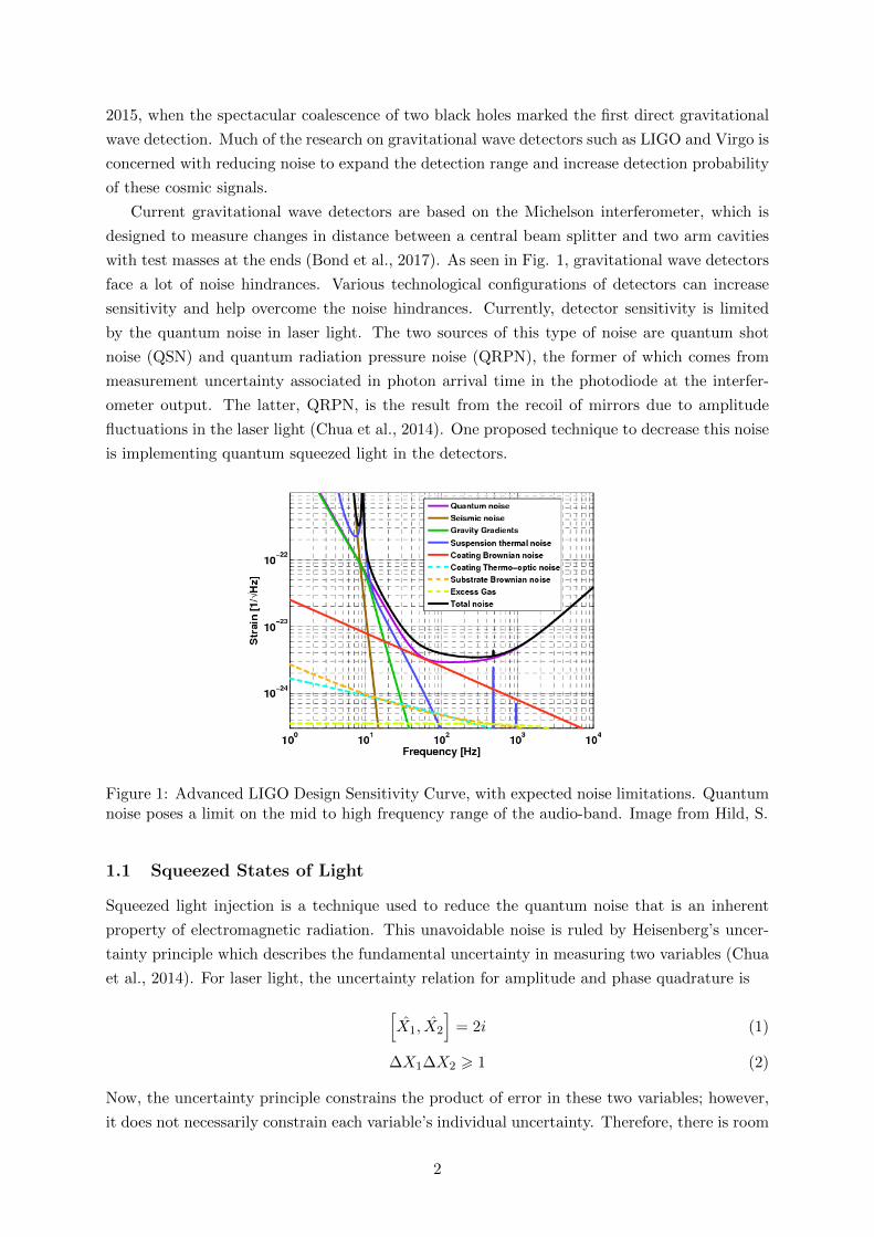
with test masses at the ends (Bond et al., 2017). As seen in Fig. 1, gravitational wave detectors
face a lot of noise hindrances. Various technological configurations of detectors can increase
sensitivity and help overcome the noise hindrances. Currently, detector sensitivity is limited
by the quantum noise in laser light. The two sources of this type of noise are quantum shot
noise (QSN) and quantum radiation pressure noise (QRPN), the former of which comes from
measurement uncertainty associated in photon arrival time in the photodiode at the interfer-
ometer output. The latter, QRPN, is the result from the recoil of mirrors due to amplitude
fluctuations in the laser light (Chua et al., 2014). One proposed technique to decrease this noise
is implementing quantum squeezed light in the detectors.
Figure 1: Advanced LIGO Design Sensitivity Curve, with expected noise limitations. Quantumnoise poses a limit on the mid to high frequency range of the audio-band. Image from Hild, S.
1.1 Squeezed States of Light
Squeezed light injection is a technique used to reduce the quantum noise that is an inherent
property of electromagnetic radiation. This unavoidable noise is ruled by Heisenberg’s uncer-
tainty principle which describes the fundamental uncertainty in measuring two variables (Chua
et al., 2014). For laser light, the uncertainty relation for amplitude and phase quadrature is
[X1, X2
]= 2i (1)
∆X1∆X2 > 1 (2)
Now, the uncertainty principle constrains the product of error in these two variables; however,
it does not necessarily constrain each variable’s individual uncertainty. Therefore, there is room
2
for manipulation. Uncertainty in one variable can be decreased in exchange for the increase in
uncertainty in the other’s as long as the product still obeys Heisenberg’s uncertainty principle.
Here, amplitude uncertainty is squeezed by a factor of S.
∆X1 < 1/S ∆X2 > S (3)
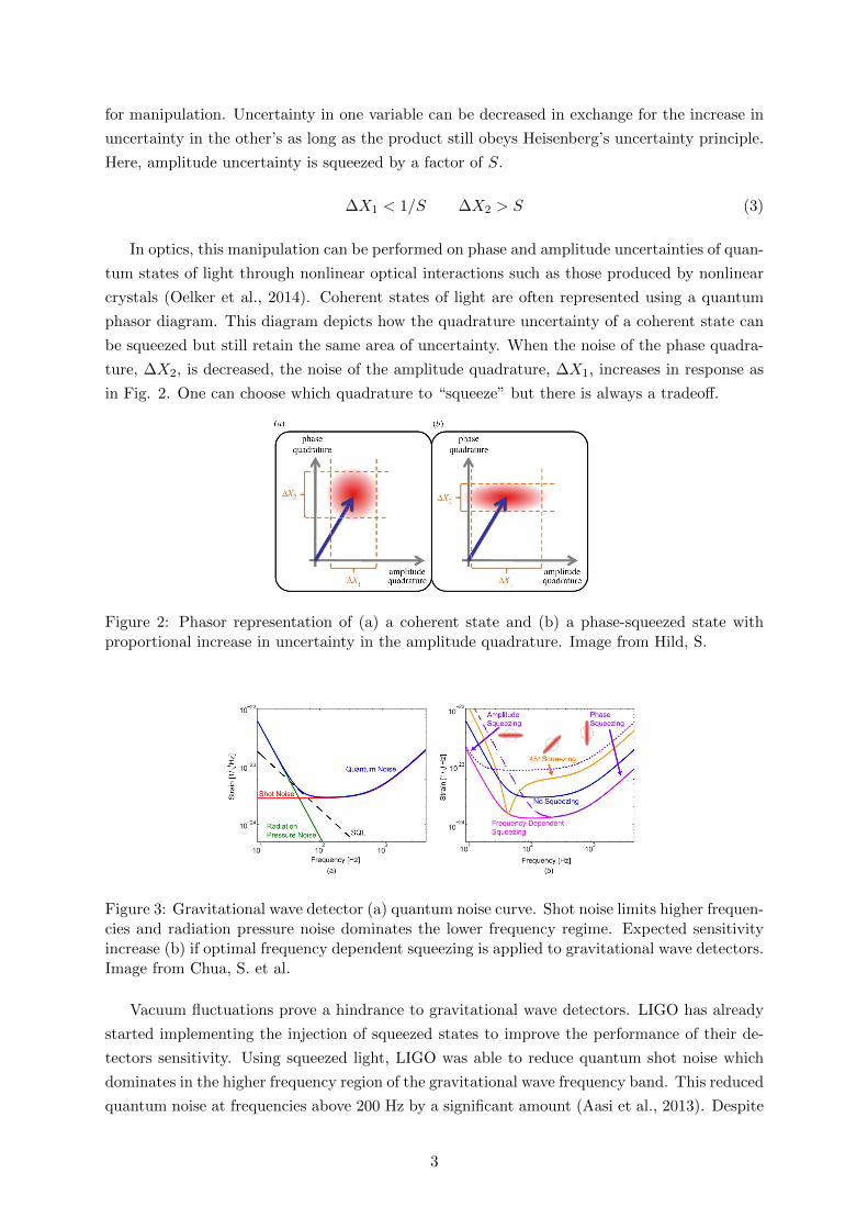
In optics, this manipulation can be performed on phase and amplitude uncertainties of quan-
tum states of light through nonlinear optical interactions such as those produced by nonlinear
crystals (Oelker et al., 2014). Coherent states of light are often represented using a quantum
phasor diagram. This diagram depicts how the quadrature uncertainty of a coherent state can
be squeezed but still retain the same area of uncertainty. When the noise of the phase quadra-
ture, ∆X2, is decreased, the noise of the amplitude quadrature, ∆X1, increases in response as
in Fig. 2. One can choose which quadrature to “squeeze” but there is always a tradeoff.
Figure 2: Phasor representation of (a) a coherent state and (b) a phase-squeezed state withproportional increase in uncertainty in the amplitude quadrature. Image from Hild, S.
Figure 3: Gravitational wave detector (a) quantum noise curve. Shot noise limits higher frequen-cies and radiation pressure noise dominates the lower frequency regime. Expected sensitivityincrease (b) if optimal frequency dependent squeezing is applied to gravitational wave detectors.Image from Chua, S. et al.
Vacuum fluctuations prove a hindrance to gravitational wave detectors. LIGO has already
started implementing the injection of squeezed states to improve the performance of their de-
tectors sensitivity. Using squeezed light, LIGO was able to reduce quantum shot noise which
dominates in the higher frequency region of the gravitational wave frequency band. This reduced
quantum noise at frequencies above 200 Hz by a significant amount (Aasi et al., 2013). Despite
3
the initial success of this project, it did not tackle the limit of radiation pressure noise in the
lower frequency region as it was not a concern since the detectors did not have the sensitivity
to encounter QRPN in the lower frequency range at that time. The two types of quantum noise
have a greater effect in different regions of the gravitational wave frequency band. Thus, it is
naturally ideal to introduce frequency dependent squeezed light to avoid degrading sensitivity
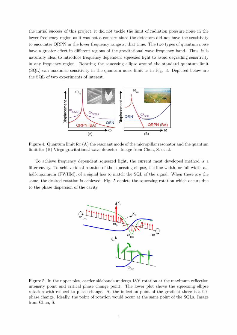
in any frequency region. Rotating the squeezing ellipse around the standard quantum limit
(SQL) can maximize sensitivity in the quantum noise limit as in Fig. 3. Depicted below are
the SQL of two experiments of interest.
Figure 4: Quantum limit for (A) the resonant mode of the micropillar resonator and the quantumlimit for (B) Virgo gravitational wave detector. Image from Chua, S. et al.
To achieve frequency dependent squeezed light, the current most developed method is a
filter cavity. To achieve ideal rotation of the squeezing ellipse, the line width, or full-width-at-
half-maximum (FWHM), of a signal has to match the SQL of the signal. When these are the
same, the desired rotation is achieved. Fig. 5 depicts the squeezing rotation which occurs due
to the phase dispersion of the cavity.
Figure 5: In the upper plot, carrier sidebands undergo 180◦ rotation at the maximum reflectionintensity point and critical phase change point. The lower plot shows the squeezing ellipserotation with respect to phase change. At the inflection point of the gradient there is a 90◦
phase change. Ideally, the point of rotation would occur at the same point of the SQLs. Imagefrom Chua, S.
4
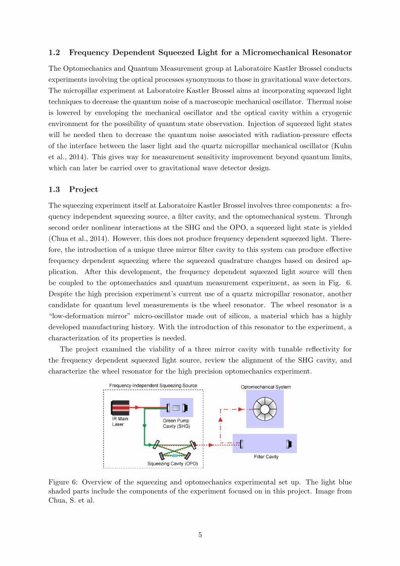
1.2 Frequency Dependent Squeezed Light for a Micromechanical Resonator
The Optomechanics and Quantum Measurement group at Laboratoire Kastler Brossel conducts
experiments involving the optical processes synonymous to those in gravitational wave detectors.
The micropillar experiment at Laboratoire Kastler Brossel aims at incorporating squeezed light
techniques to decrease the quantum noise of a macroscopic mechanical oscillator. Thermal noise
is lowered by enveloping the mechanical oscillator and the optical cavity within a cryogenic
environment for the possibility of quantum state observation. Injection of squeezed light states
will be needed then to decrease the quantum noise associated with radiation-pressure effects
of the interface between the laser light and the quartz micropillar mechanical oscillator (Kuhn
et al., 2014). This gives way for measurement sensitivity improvement beyond quantum limits,
which can later be carried over to gravitational wave detector design.
1.3 Project
The squeezing experiment itself at Laboratoire Kastler Brossel involves three components: a fre-
quency independent squeezing source, a filter cavity, and the optomechanical system. Through
second order nonlinear interactions at the SHG and the OPO, a squeezed light state is yielded
(Chua et al., 2014). However, this does not produce frequency dependent squeezed light. There-
fore, the introduction of a unique three mirror filter cavity to this system can produce effective
frequency dependent squeezing where the squeezed quadrature changes based on desired ap-
plication. After this development, the frequency dependent squeezed light source will then
be coupled to the optomechanics and quantum measurement experiment, as seen in Fig. 6.
Despite the high precision experiment’s current use of a quartz micropillar resonator, another
candidate for quantum level measurements is the wheel resonator. The wheel resonator is a
“low-deformation mirror” micro-oscillator made out of silicon, a material which has a highly
developed manufacturing history. With the introduction of this resonator to the experiment, a
characterization of its properties is needed.
The project examined the viability of a three mirror cavity with tunable reflectivity for
the frequency dependent squeezed light source, review the alignment of the SHG cavity, and
characterize the wheel resonator for the high precision optomechanics experiment.
Figure 6: Overview of the squeezing and optomechanics experimental set up. The light blueshaded parts include the components of the experiment focused on in this project. Image fromChua, S. et al.
5
2 Three Mirror Filter Cavity
To achieve ideal frequency dependent squeezing, half the full-width-at-half-maximum of the
filter cavity must be the same as the standard quantum limit Fourier frequency (in the case for
gravitational wave interferometers). However, the SQL Fourier frequency is dependent on dif-
ferent experimental factors that can change. Therefore, a filter cavity that can tune its FWHM
would be ideal to follow the changes in SQL Fourier frequency. The FWHM of a cavity signal
in conjunction with free spectral range (spacing of adjacent resonance) gives the finesse of a op-
tical system, which characterizes as the Q factor does to a mechanical system. Eq. 4, describes
FWHM as a relationship of free spectral range, FSR, and finesse, F . In addition, in Eq. 4,
FWHM is given as a function of the reflectivities of the cavity mirrors, r1 and r2, cavity length,
L, and the speed of light, c.
FWHM =FSR
FFWHM =
c
2L
(1− r1r2)πr1r2
(4)
Changing mirrors every time to adjust FWHM is not efficient. A cavity with tunable reflec-
tivities is necessary. We can devise a cavity system with this ability by replacing the front
mirror of a Fabry-Perot cavity with an additional cavity. This introduced cavity can adjust
its reflectivity by changing cavity length. Since this two mirror front cavity has a total reflec-
tion and transmission amplitude it is not unlike a singular mirror component which similarly
has its own reflection and transmission amplitude. Hence, the first cavity acts as a “mirror”
with adjustable reflectivity. With this, the FWHM of the whole three mirror system can be
adjusted by simply changing the length of the first cavity which changes the reflectivity of the
first “mirror.” The FWHM can be tuned to match SQL Fourier frequencies and achieve optimal
frequency dependent squeezing for different systems.
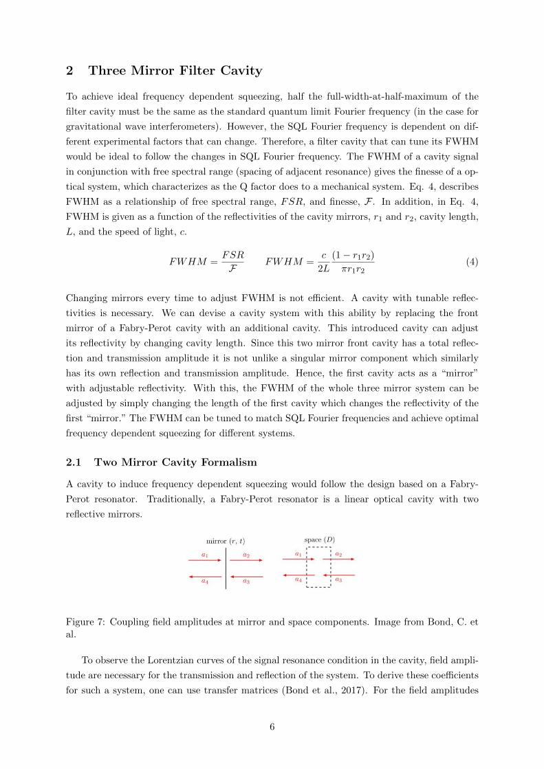
2.1 Two Mirror Cavity Formalism
A cavity to induce frequency dependent squeezing would follow the design based on a Fabry-
Perot resonator. Traditionally, a Fabry-Perot resonator is a linear optical cavity with two
reflective mirrors.
Figure 7: Coupling field amplitudes at mirror and space components. Image from Bond, C. etal.
To observe the Lorentzian curves of the signal resonance condition in the cavity, field ampli-
tude are necessary for the transmission and reflection of the system. To derive these coefficients
for such a system, one can use transfer matrices (Bond et al., 2017). For the field amplitudes
6
at a mirror as in Fig. 7, the transfer matrix is as follows, where r and t each represent the
amplitude reflectivities and amplitude transmittances respectively.(a1
a4
)=i
t
(−1 r
−r r2 + t2
)(a2
a3
)(5)
Field amplitudes in free space, as within a cavity and as seen in Fig 6, are described by the
following transfer matrix. Here, D describes the length of the free space in which the field
propagates and k describes the wavenumber of the field.(a1
a4
)=
(eikD 0
0 e−ikD
)(a2
a3
)(6)
With these matrices the transfer matrix for a Fabry-Perot cavity can be computed. This
matrix describing the system, in Eq. 7 and Eq. 8, contains the reflection and transmission field
amplitudes of the first mirror, r1 and t1, and the reflection and transmission field amplitudes
of the back mirror, r2 and t2, along with the free space within the cavity.
Mcav = Mmirror ×Mspace ×Mmirror (7)
=−1
t1t2
(eikD − r1r2e−ikD −r2eikD + r1e
−ikD
−r2e−ikD + r1eikD e−ikD − r1r2eikD
)(8)
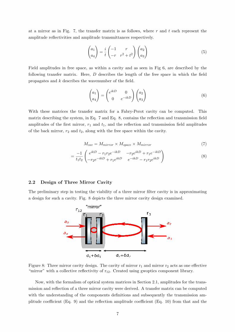
2.2 Design of Three Mirror Cavity
The preliminary step in testing the viability of a three mirror filter cavity is in approximating
a design for such a cavity. Fig. 8 depicts the three mirror cavity design examined.
Figure 8: Three mirror cavity design. The cavity of mirror r1 and mirror r2 acts as one effective“mirror” with a collective reflectivity of r12. Created using gwoptics component library.
Now, with the formalism of optical system matrices in Section 2.1, amplitudes for the trans-
mission and reflection of a three mirror cavity were derived. A transfer matrix can be computed
with the understanding of the components definitions and subsequently the transmission am-
plitude coefficient (Eq. 9) and the reflection amplitude coefficient (Eq. 10) from that and the
7
scattering matrix.
a2a0
=eid1k+id2kt1t2t3
(1− e2id1kr1r2)(1− e2id2kr3(r1 +e2id1kr2t21
1−e2id1kr1r2))
(9)
a4a0
= r1 +e2id1kr2t
21
1− e2id1kr1r2+
e(2id1k+2id2k)r3t21t
22
(1− e2id1kr1r2)2(1− e2id2kr3(r1 +e2id1kr2t21
1−e2id1kr1r2))
(10)
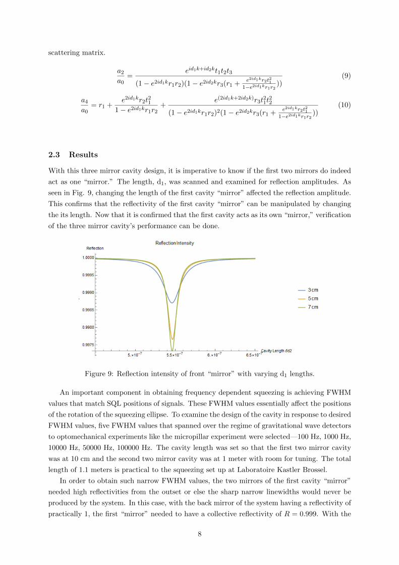
2.3 Results
With this three mirror cavity design, it is imperative to know if the first two mirrors do indeed
act as one “mirror.” The length, d1, was scanned and examined for reflection amplitudes. As
seen in Fig. 9, changing the length of the first cavity “mirror” affected the reflection amplitude.
This confirms that the reflectivity of the first cavity “mirror” can be manipulated by changing
the its length. Now that it is confirmed that the first cavity acts as its own “mirror,” verification
of the three mirror cavity’s performance can be done.
Figure 9: Reflection intensity of front “mirror” with varying d1 lengths.
An important component in obtaining frequency dependent squeezing is achieving FWHM
values that match SQL positions of signals. These FWHM values essentially affect the positions
of the rotation of the squeezing ellipse. To examine the design of the cavity in response to desired
FWHM values, five FWHM values that spanned over the regime of gravitational wave detectors
to optomechanical experiments like the micropillar experiment were selected—100 Hz, 1000 Hz,
10000 Hz, 50000 Hz, 100000 Hz. The cavity length was set so that the first two mirror cavity
was at 10 cm and the second two mirror cavity was at 1 meter with room for tuning. The total
length of 1.1 meters is practical to the squeezing set up at Laboratoire Kastler Brossel.
In order to obtain such narrow FWHM values, the two mirrors of the first cavity “mirror”
needed high reflectivities from the outset or else the sharp narrow linewidths would never be
produced by the system. In this case, with the back mirror of the system having a reflectivity of
practically 1, the first “mirror” needed to have a collective reflectivity of R = 0.999. With the
8
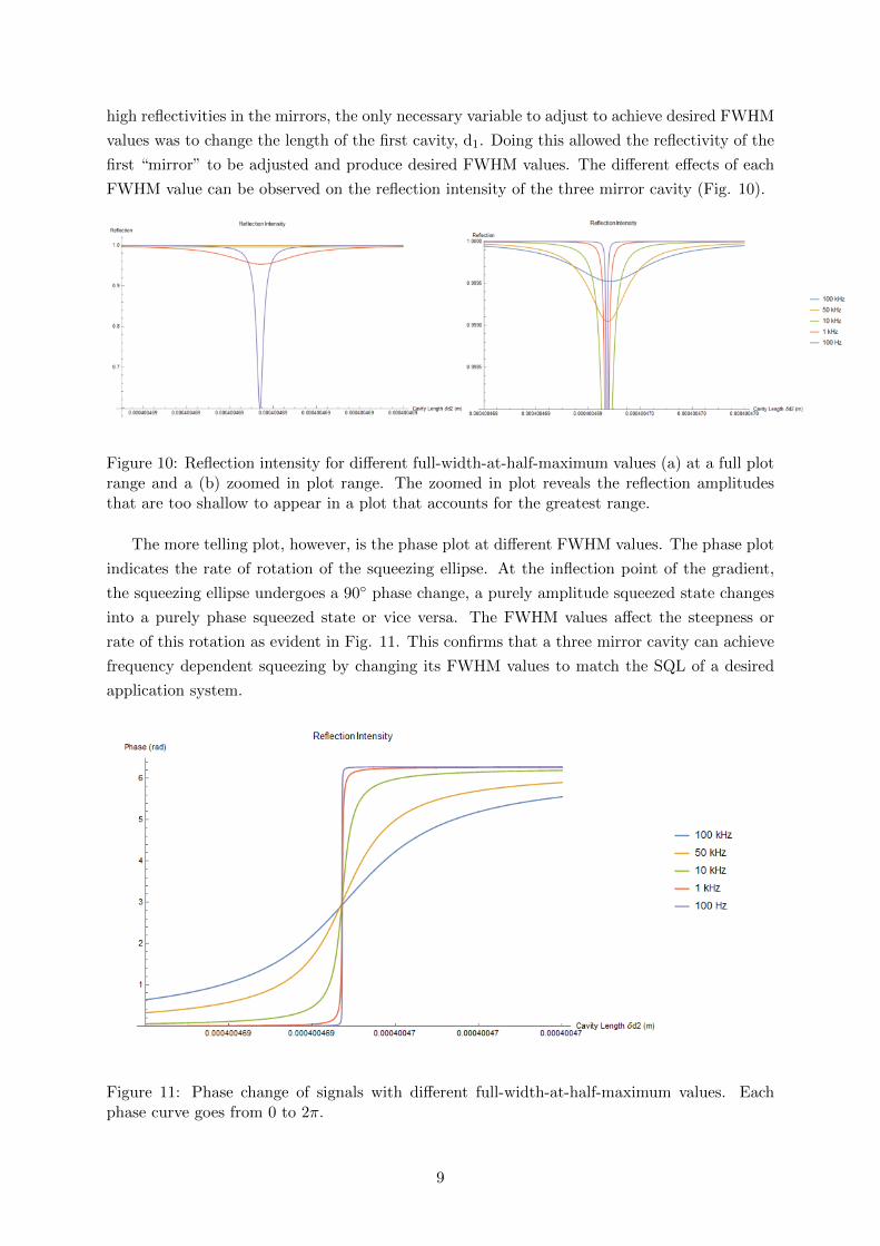
high reflectivities in the mirrors, the only necessary variable to adjust to achieve desired FWHM
values was to change the length of the first cavity, d1. Doing this allowed the reflectivity of the
first “mirror” to be adjusted and produce desired FWHM values. The different effects of each
FWHM value can be observed on the reflection intensity of the three mirror cavity (Fig. 10).
Figure 10: Reflection intensity for different full-width-at-half-maximum values (a) at a full plotrange and a (b) zoomed in plot range. The zoomed in plot reveals the reflection amplitudesthat are too shallow to appear in a plot that accounts for the greatest range.
The more telling plot, however, is the phase plot at different FWHM values. The phase plot
indicates the rate of rotation of the squeezing ellipse. At the inflection point of the gradient,
the squeezing ellipse undergoes a 90◦ phase change, a purely amplitude squeezed state changes
into a purely phase squeezed state or vice versa. The FWHM values affect the steepness or
rate of this rotation as evident in Fig. 11. This confirms that a three mirror cavity can achieve
frequency dependent squeezing by changing its FWHM values to match the SQL of a desired
application system.
Figure 11: Phase change of signals with different full-width-at-half-maximum values. Eachphase curve goes from 0 to 2π.
9
3 Alignment of Second Harmonic Generator Cavity
The Second Harmonic Generator (SHG) is an important component in the squeezing setup. It
is where one of the nonlinear optical stages occur in the generation of squeezed light. The SHG
consists of a nonlinear crystal in an oven within a Fabry-Perot cavity. At the SHG, the main
laser is frequency doubled though the interaction with a nonlinear crystal which is kept at a
stable temperature. In the nonlinear interaction, by the conservation of energy, the main laser
is frequency doubled. This degenerate nonlinear optical process, therefore, converts 1064 nm
light to 532 nm and sends it to the remaining parts of the squeezing set up, such as the Optical
Parametric Oscillator (OPO).
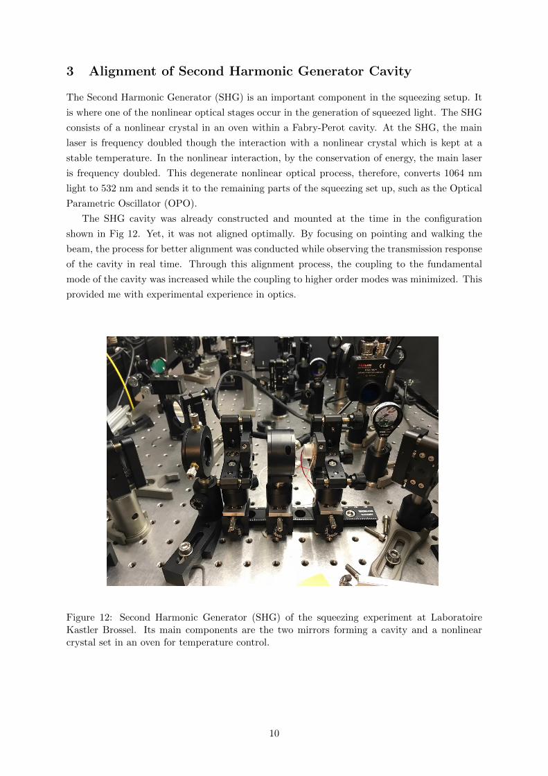
The SHG cavity was already constructed and mounted at the time in the configuration
shown in Fig 12. Yet, it was not aligned optimally. By focusing on pointing and walking the
beam, the process for better alignment was conducted while observing the transmission response
of the cavity in real time. Through this alignment process, the coupling to the fundamental
mode of the cavity was increased while the coupling to higher order modes was minimized. This
provided me with experimental experience in optics.
Figure 12: Second Harmonic Generator (SHG) of the squeezing experiment at LaboratoireKastler Brossel. Its main components are the two mirrors forming a cavity and a nonlinearcrystal set in an oven for temperature control.
10

4 Characterization of the Wheel Resonator
4.1 A “Low-Deformation” Mirror
The wheel resonator is a candidate for high precision measurement experiments in optome-
chanics. With its high optical finesse of 4 × 10⁴ and high mechanical quality factor of 105,
the micro-oscillator has ultra-low optical and mechanical losses (Serra et al., 2012). In con-
struction, the wheel resonator is a resonator made out of thick silicon with a highly reflective
mirror coating which yields high quality factors. The “low deformation” design is supported by
torsional springs to avoid rotation and flexural springs for uniform vertical displacement of the
mirror sans bending as seen in Fig. 13 and Fig. 14. It is a potential device to be complimen-
tary to Laboratoire Kastler Brossel’s quartz micropillar resonator because of the technological
developments in silicon. Therefore an initial characterization of this device was conducted.
Figure 13: Scanning electron microscope image of (a) front side and (b) back side of a “low-deformation mirror” resonator made of silicon with high reflectivity coating. Image from Serra,E. et al.
Figure 14: Modal representation of two designs. The (a) ”low-deformation mirror” providesuniform displacement unlike the (b) previous design. Image from Serra, E. et al.
4.2 Results
To characterize the wheel resonator, mechanically-driven response measurements and ringdown
measurements were made using a simple Michelson interferometer set up as shown in Fig. 15. To
take these measurements, firstly, many alignments were needed to guarantee high fringe contrast,
involving maximal fringe amplitude size, as an electrical signal scanned arm length changes with
a piezo-electric actuator (PZT) in the local oscillator path. This involved aligning various lenses
and both the local oscillator and wheel resonator paths by walking the beam. Then, once the
Michelson interferometer was optimally aligned, the resonance frequency was recorded using a
network analyzer to measure the PZT-driven displacement of the wheel resonator. This can
11
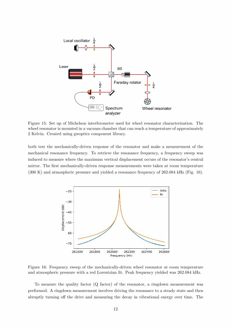
Figure 15: Set up of Michelson interferometer used for wheel resonator characterization. Thewheel resonator is mounted in a vacuum chamber that can reach a temperature of approximately2 Kelvin. Created using gwoptics component library.
both test the mechanically-driven response of the resonator and make a measurement of the
mechanical resonance frequency. To retrieve the resonance frequency, a frequency sweep was
induced to measure where the maximum vertical displacement occurs of the resonator’s central
mirror. The first mechanically-driven response measurements were taken at room temperature
(300 K) and atmospheric pressure and yielded a resonance frequency of 262.084 kHz (Fig. 16).
Figure 16: Frequency sweep of the mechanically-driven wheel resonator at room temperatureand atmospheric pressure with a red Lorentzian fit. Peak frequency yielded was 262.084 kHz.
To measure the quality factor (Q factor) of the resonator, a ringdown measurement was
performed. A ringdown measurement involves driving the resonance to a steady state and then
abruptly turning off the drive and measuring the decay in vibrational energy over time. The
12
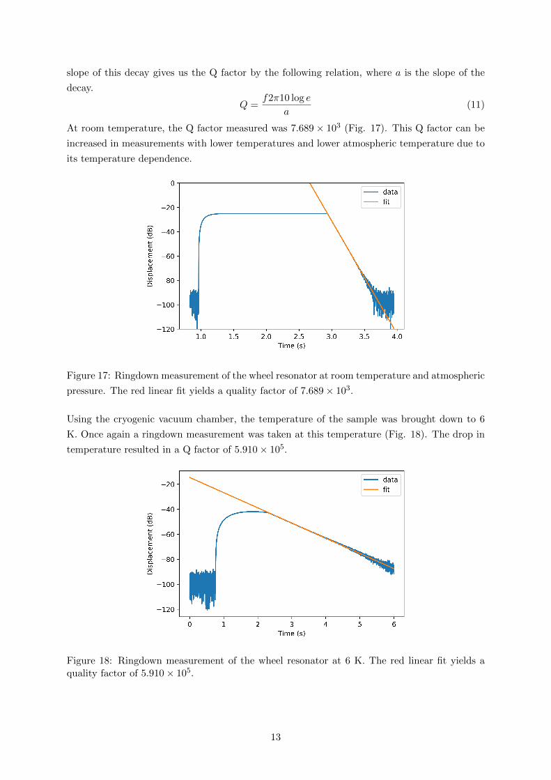
slope of this decay gives us the Q factor by the following relation, where a is the slope of the
decay.
Q =f2π10 log e
a(11)
At room temperature, the Q factor measured was 7.689× 10³ (Fig. 17). This Q factor can be
increased in measurements with lower temperatures and lower atmospheric temperature due to
its temperature dependence.
Figure 17: Ringdown measurement of the wheel resonator at room temperature and atmospheric
pressure. The red linear fit yields a quality factor of 7.689× 10³.
Using the cryogenic vacuum chamber, the temperature of the sample was brought down to 6
K. Once again a ringdown measurement was taken at this temperature (Fig. 18). The drop in
temperature resulted in a Q factor of 5.910× 10⁵.
Figure 18: Ringdown measurement of the wheel resonator at 6 K. The red linear fit yields aquality factor of 5.910× 10⁵.
13
5 Conclusion
This project investigated the feasibility of a three mirror filter cavity and characterized a micro-
resonator for the high precision measurement experiments at Laboratoire Kastler Brossel. From
the results, it can be concluded that a three mirror filter cavity design is a feasible system to
produce adjustable reflectivity and hence adjustable FWHM. This is essential for frequency
dependent squeezing and therefore its production would be novel for the quantum measurement
experiment at Laboratoire Kastler Brossel. The next step is to consider further features for its
future implementation. For example, the investigation conducted assumed plane waves rather
than Gaussian beams. In addition, a hybrid Pound-Drever-Hall technique needs to be added
to this system for locking the system at desired conditions. This poses quite an obstacle for a
two cavities coupled design leaving no space for locking technique for the cavity of the first two
mirrors.
The initial characterization of the wheel resonator yielded reasonable data. Yet, as with
most experiments, many more trials of the resonance frequency and Q factor measurements
must be conducted to get robust results for the wheel resonator before its use in the quantum
measurement experiment. The wheel resonator already proves complimentary due to its con-
struction out of silicon a material with a more technologically developed manufacturing history
than the quartz in the original micropillar resonator.
Aligning the SHG and Michelson interferometer provided me with my first experimental
experience with optics. I learned about the techniques for alignment including beam pointing
and walking the beam. Aligning the SHG allowed me to examine coupling to the fundamental
mode of the cavity. Optimizing the Michelson interferometer also proved important in revealing
how important optimal alignment is in later measurement accuracy.
14
Acknowledgements
I would like to sincerely thank everyone in the Optomechanics and Quantum Measurement
group at Laboratoire Kastler Brossel for welcoming me into their lab. In particular, I would
like to thank Sheon Chua, Pierre-Francois Cohadon, and Remi Metzdorff for not only involving
me in their projects but also imparting an immense amount of optomechanics knowledge and
experimental experience. I would also like to thank Guido Mueller, Bernard Whiting, and
Kristin Nichola for organizing this program and offering me this opportunity. Lastly, I would
like to thank the National Science Foundation for funding this international REU program in
gravitational physics.
15
References
J. Aasi, J. Abadie, B. P. Abbott, R. Abbott, T. D. Abbott, M. R. Abernathy, C. Adams,
T. Adams, P. Addesso, R. X. Adhikari, and et al. Enhanced sensitivity of the LIGO gravita-
tional wave detector by using squeezed states of light. Nature Photonics, 7:613–619, August
2013. doi: 10.1038/nphoton.2013.177.
B. P. Abbott, R. Abbott, T. D. Abbott, M. R. Abernathy, F. Acernese, K. Ackley, C. Adams,
T. Adams, P. Addesso, R. X. Adhikari, and et al. Observation of Gravitational Waves from
a Binary Black Hole Merger. Physical Review Letters, 116(6):061102, February 2016. doi:
10.1103/PhysRevLett.116.061102.
Charlotte Bond, Daniel Brown, Andreas Freise, and Kenneth A. Strain. Interferometer tech-
niques for gravitational-wave detection. Living Reviews in Relativity, 19(1):3, Feb 2017. ISSN
1433-8351. doi: 10.1007/s41114-016-0002-8. URL https://doi.org/10.1007/s41114-016-
0002-8.
S. S. Y. Chua, B. J. J. Slagmolen, D. A. Shaddock, and D. E. McClelland. Quantum squeezed
light in gravitational-wave detectors. Classical and Quantum Gravity, 31(18):183001, 2014.
URL http://stacks.iop.org/0264-9381/31/i=18/a=183001.
S. Hild. Beyond the second generation of laser-interferometric gravitational wave observatories.
Classical and Quantum Gravity, 29(12):124006, June 2012. doi: 10.1088/0264-9381/29/12/
124006.
Aurlien Kuhn, Leonhard Neuhaus, Emmanuel Van Brackel, Claude Chartier, Olivier Ducloux,
Olivier Le Traon, Christophe Michel, Laurent Pinard, Raffaele Flaminio, Samuel Delglise,
Tristan Briant, Pierre-Franois Cohadon, and Antoine Heidmann. A micropillar for cavity
optomechanics. AIP Conference Proceedings, 1633(1):68–70, 2014. doi: 10.1063/1.4903097.
URL https://aip.scitation.org/doi/abs/10.1063/1.4903097.
E. Oelker, L. Barsotti, S. Dwyer, D. Sigg, and N. Mavalvala. Squeezed light for advanced
gravitational wave detectors and beyond. Opt. Express, 22(17):21106–21121, Aug 2014. doi:
10.1364/OE.22.021106. URL http://www.opticsexpress.org/abstract.cfm?URI=oe-22-
17-21106.
E. Serra, A. Borrielli, F. S. Cataliotti, F. Marin, F. Marino, A. Pontin, G. A. Prodi, and
M. Bonaldi. A low-deformation mirror micro-oscillator with ultra-low optical and mechanical
losses. Applied Physics Letters, 101(7):071101, 2012. doi: 10.1063/1.4745510. URL https:
//doi.org/10.1063/1.4745510.
16
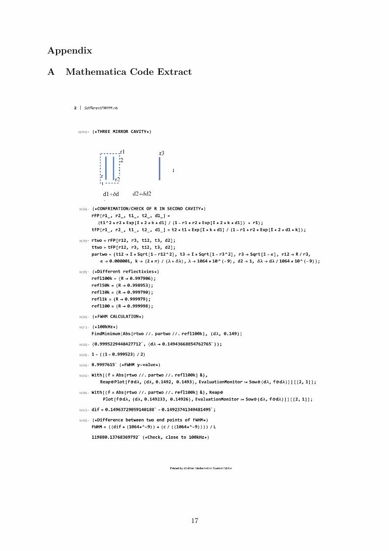
Appendix
A Mathematica Code Extract
17
18
19