FREQUENCY CHARACTERISTICS: A SOURCE OF INFORMATION IN PHOTOACOUSTICS Mirosław Maliński Department...
31
FREQUENCY CHARACTERISTICS: A SOURCE OF INFORMATION IN PHOTOACOUSTICS Mirosław Maliński Department of Electronics and Computer Studies Technical Univeristy of Koszalin, Poland
-
Upload
coleen-mosley -
Category
Documents
-
view
215 -
download
1
Transcript of FREQUENCY CHARACTERISTICS: A SOURCE OF INFORMATION IN PHOTOACOUSTICS Mirosław Maliński Department...
FREQUENCY CHARACTERISTICS: A SOURCE OF INFORMATION IN
PHOTOACOUSTICS
Mirosław MalińskiDepartment of Electronics and Computer
StudiesTechnical Univeristy of Koszalin, Poland
Contents
IntroductionMultilayer optically opaque systemsOptically semitransparent systemsDetermination of thermal parametersDetermination of recombination parametersAir-tightness measurements of packagings
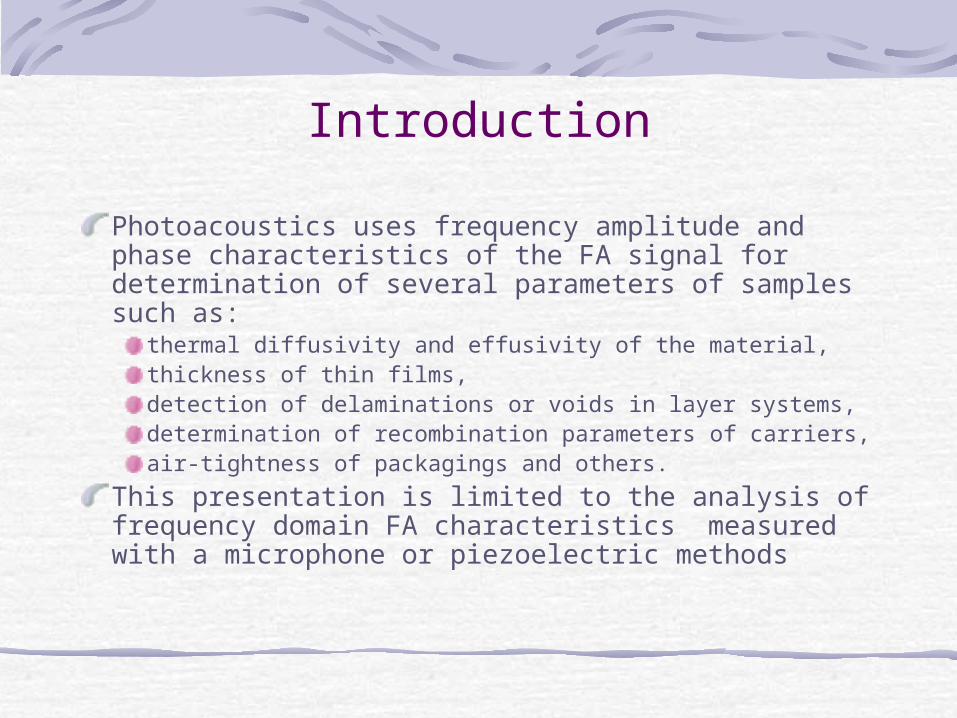
Introduction
Photoacoustics uses frequency amplitude and phase characteristics of the FA signal for determination of several parameters of samples such as:
thermal diffusivity and effusivity of the material,thickness of thin films, detection of delaminations or voids in layer systems, determination of recombination parameters of carriers, air-tightness of packagings and others.
This presentation is limited to the analysis of frequency domain FA characteristics measured with a microphone or piezoelectric methods
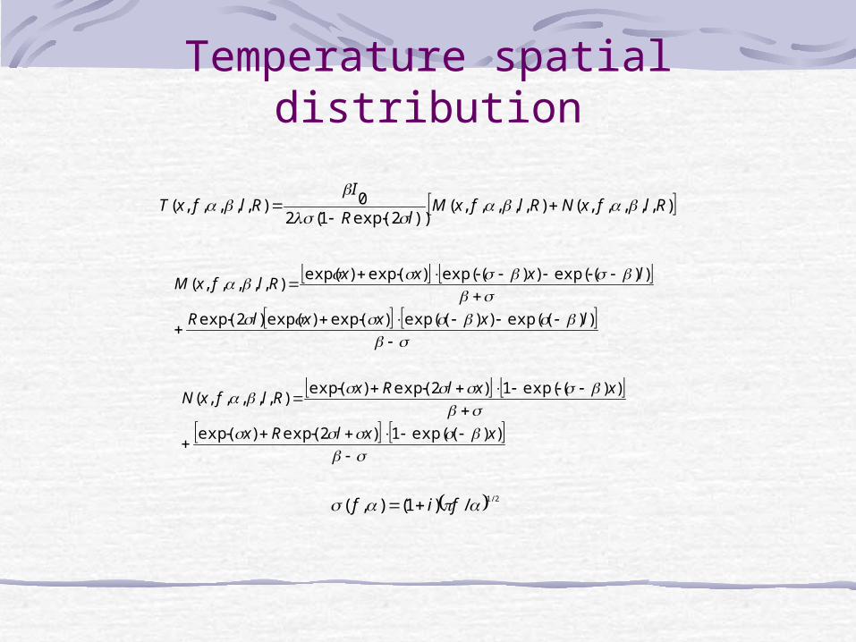
Temperature spatial distribution
),,,,,(),,,,,())2exp(1(2
0),,,,,( RlfxNRlfxMlR
IRlfxT
))exp(())exp(()exp()exp()2exp(
))exp(())exp(()exp()exp(),,,,,(
lxxxlR
lxxxRlfxM
))exp((1)2exp()exp(
))exp((1)2exp()exp(),,,,,(
xxlRx
xxlRxRlfxN
2/1/)1(),( fif
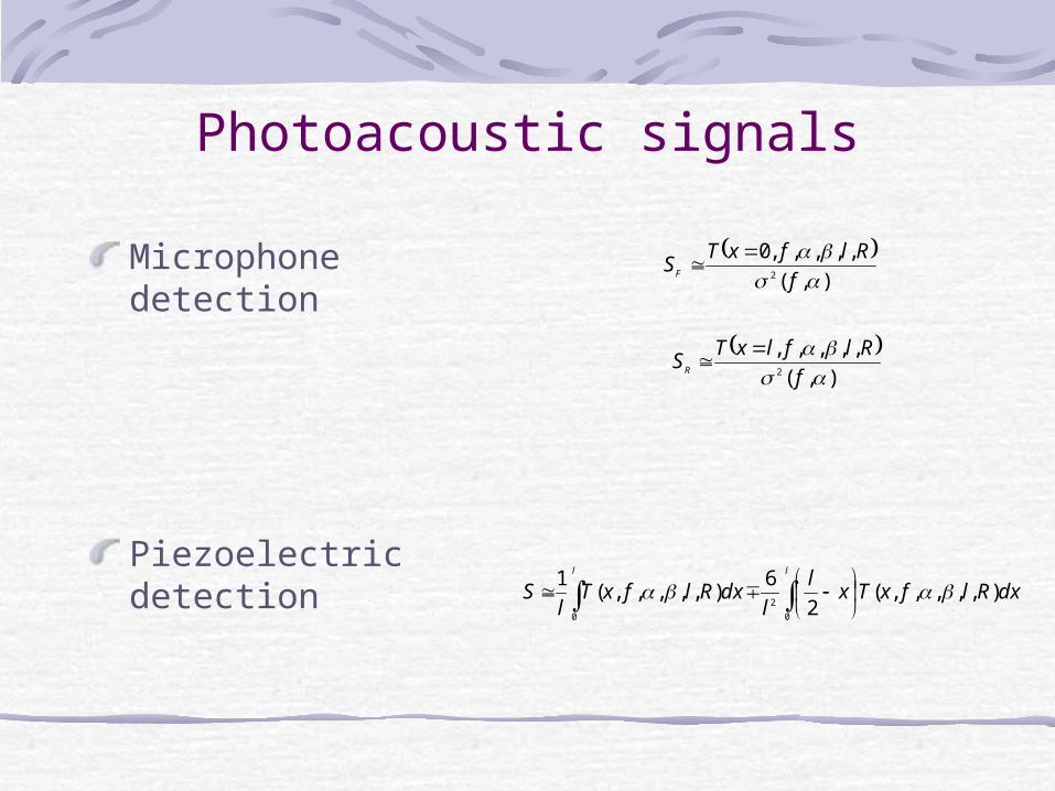
Photoacoustic signals
Microphone detection
Piezoelectric detection
),(
,,,,,02
f
RlfxTSF
ll
dxRlfxTxl
ldxRlfxT
lS
0
2
0
),,,,,(2
6),,,,,(
1
),(
,,,,,2
f
RlflxTSR
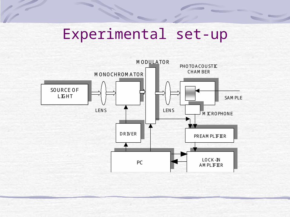
Experimental set-up
SAMPLE
DRIVER
PHOTOACOUSTIC CHAMBER
MICROPHONE
LOCK-IN AMPLIFIER
MODULATOR
SOURCE OF LIGHT
LENS
MONOCHROMATOR
LENS
PREAMPLIFIER
PC
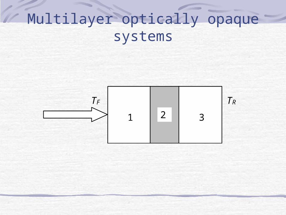
Multilayer optically opaque systems
TF TR
1 2 3
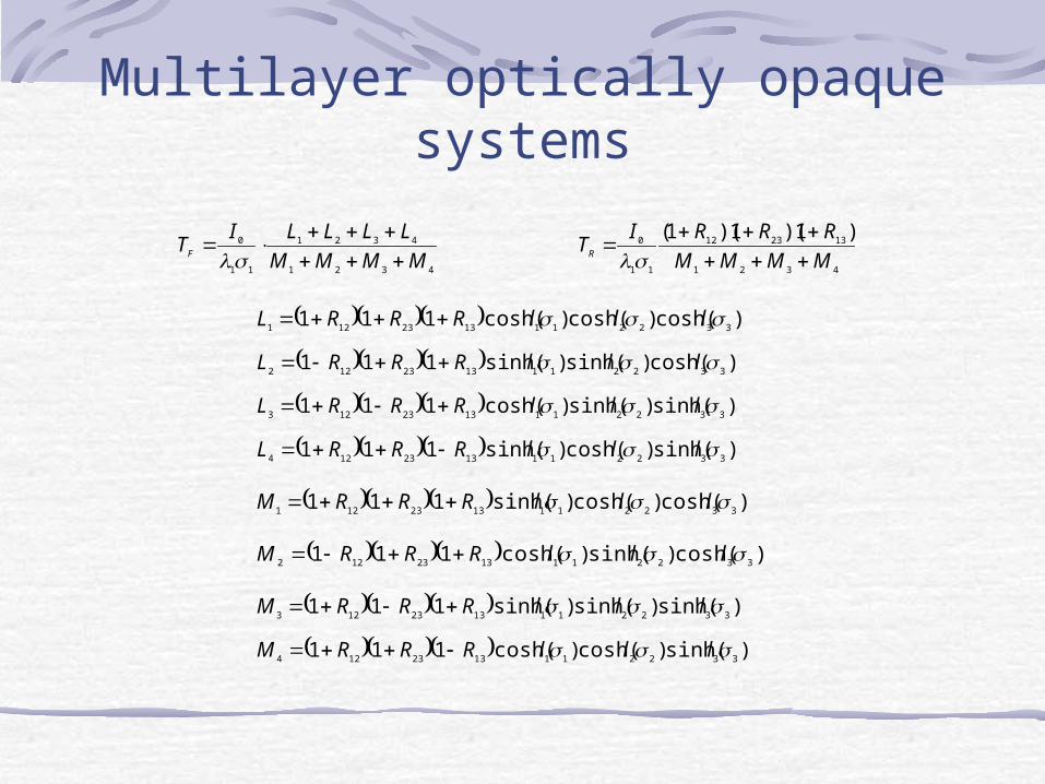
Multilayer optically opaque systems
4321
4321
11
0
MMMM
LLLLITF
4321
132312
11
0 )1)(1)(1(
MMMM
RRRITR
)cosh()cosh()cosh(111 3322111323121 lllRRRL
)cosh()sinh()sinh(111 3322111323122 lllRRRL
)sinh()sinh()cosh(111 3322111323123 lllRRRL
)sinh()cosh()sinh(111 3322111323124 lllRRRL
)cosh()cosh()sinh(111 3322111323121 lllRRRM
)cosh()sinh()cosh(111 3322111323122 lllRRRM
)sinh()sinh()sinh(111 3322111323123 lllRRRM
)sinh()cosh()cosh(111 3322111323124 lllRRRM
Multilayer optically opaque systems
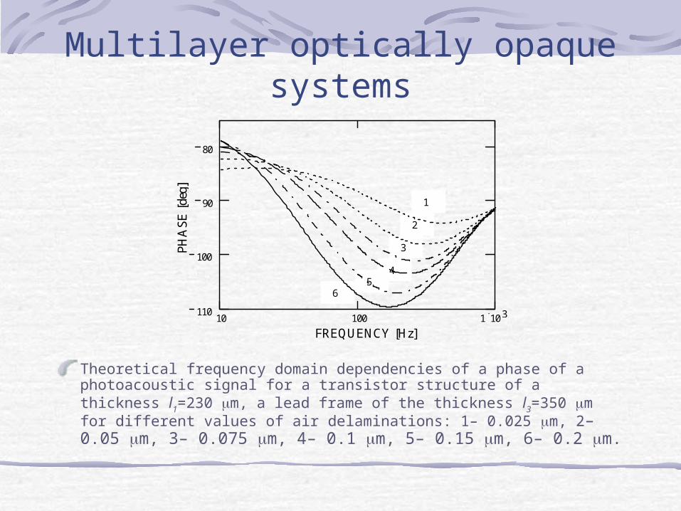
Theoretical frequency domain dependencies of a phase of a photoacoustic signal for a transistor structure of a thickness l1=230 m, a lead frame of the thickness l3=350 m for different values of air delaminations: 1– 0.025 m, 2– 0.05 m, 3– 0.075 m, 4– 0.1 m, 5– 0.15 m, 6– 0.2 m.
6 5
4
3
2
1
10 100 1 10 3 110
100
90
80
FREQUENCY [Hz]
PH
AS
E [
deg]
Multilayer optically opaque systems
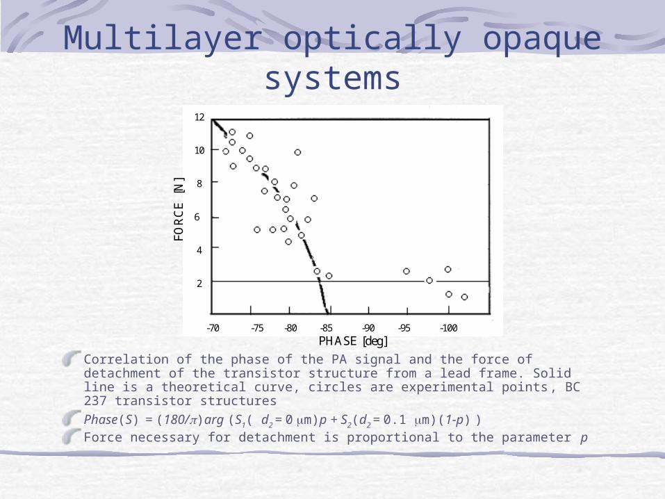
Correlation of the phase of the PA signal and the force of detachment of the transistor structure from a lead frame. Solid line is a theoretical curve, circles are experimental points, BC 237 transistor structures
Phase(S) = (180/)arg (S1( d2 = 0 m)p + S2(d2 = 0.1 m)(1-p) )Force necessary for detachment is proportional to the parameter p
PHASE [deg] -70 -75 -80 -85 -90 -95 -100
FO
RC
E [
N]
12
10
8
6
4
2
Multilayer optically opaque systems
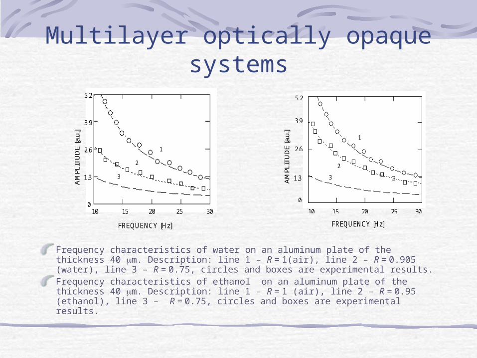
Frequency characteristics of water on an aluminum plate of the thickness 40 m. Description: line 1 – R = 1(air), line 2 – R = 0.905 (water), line 3 – R = 0.75, circles and boxes are experimental results. Frequency characteristics of ethanol on an aluminum plate of the thickness 40 m. Description: line 1 – R = 1 (air), line 2 – R = 0.95 (ethanol), line 3 – R = 0.75, circles and boxes are experimental results.
FREQUENCY [Hz]
10 15 20 25 30
5.2
3.9
2.6
1.3
0
AM
PLIT
UD
E [a
.u.]
1
2
3
FREQUENCY [Hz]
10 15 20 25 30
5.2
3.9
2.6
1.3
0
AM
PLIT
UD
E [a
.u.]
1
2
3
Optically semitransparent systems
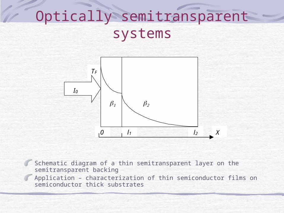
Schematic diagram of a thin semitransparent layer on the semitransparent backing Application – characterization of thin semiconductor films on semiconductor thick substrates
l2 l1 X 0
TF
I0
Optically semitransparent systems
2222111211
122110
11
1111112
11
111
111211
01
)(
)()(
)(
)(
)(
)(
)(
)exp()exp(1exp
exp12exp
exp1
2exp1
hlRlRhlI
h
lhlR
h
lh
lR
IhTF
Optically semitransparent systems
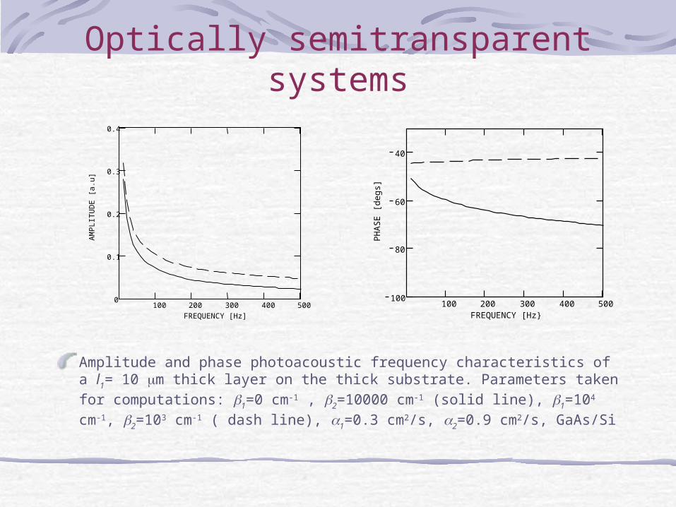
Amplitude and phase photoacoustic frequency characteristics of a l1= 10 m thick layer on the thick substrate. Parameters taken for computations: 1=0 cm-1 , 2=10000 cm-1 (solid line), 1=104 cm-1, 2=103 cm-1 ( dash line), 1=0.3 cm2/s, 2=0.9 cm2/s, GaAs/Si
100 200 300 400 5000
0.1
0.2
0.3
0.4
FREQUENCY [Hz]
AM
PL
ITU
DE
[a.
u]
100 200 300 400 500100
80
60
40
FREQUENCY [Hz}
PH
AS
E [
degs
]
Optically semitransparent systems
Application of the frequency characteristics for detection of the thickness SCL in semiconductorsComparison of the amplitude spectra and frequency characteristicsSCL- is the subsurface layer of the semiconductor where light is absorbed but does not give the contribution to the FA signal
Optically semitransparent systems
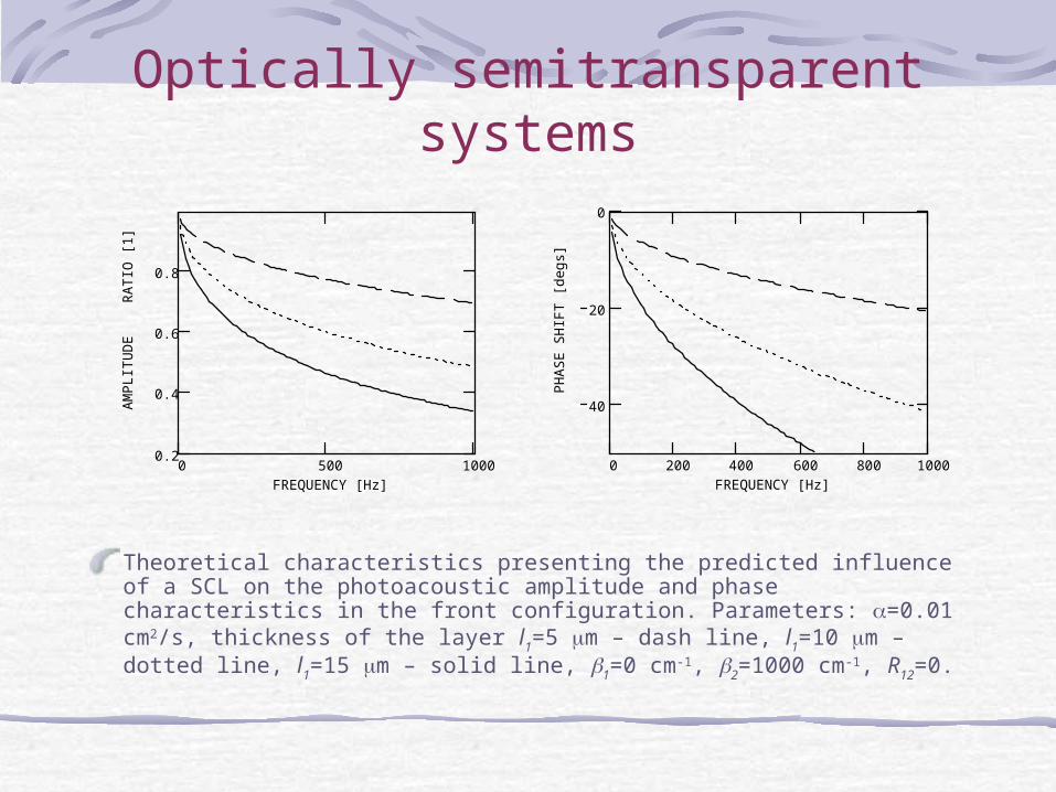
Theoretical characteristics presenting the predicted influence of a SCL on the photoacoustic amplitude and phase characteristics in the front configuration. Parameters: =0.01 cm2/s, thickness of the layer l1=5 m – dash line, l1=10 m – dotted line, l1=15 m – solid line, 1=0 cm-1, 2=1000 cm-1, R12=0.
0 500 10000.2
0.4
0.6
0.8
FREQUENCY [Hz]
AM
PL
ITU
DE
RA
TIO
[1]
0 200 400 600 800 1000
40
20
0
FREQUENCY [Hz]
PH
AS
E S
HIF
T [
degs
]
Optically semitransparent systems
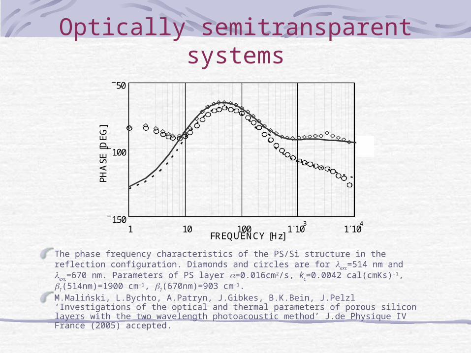
The phase frequency characteristics of the PS/Si structure in the reflection configuration. Diamonds and circles are for exc=514 nm and exc=670 nm. Parameters of PS layer =0.016cm2/s, kc=0.0042 cal(cmKs)-1, 1(514nm)=1900 cm-1, 1(670nm)=903 cm-1.M.Maliński, L.Bychto, A.Patryn, J.Gibkes, B.K.Bein, J.Pelzl ‘Investigations of the optical and thermal parameters of porous silicon layers with the two wavelength photoacoustic method’ J.de Physique IV France (2005) accepted.
1 10 100 1 10 3
1 10 4 150
100
50
FREQUENCY [Hz]
PHA
SE [
DE
G]
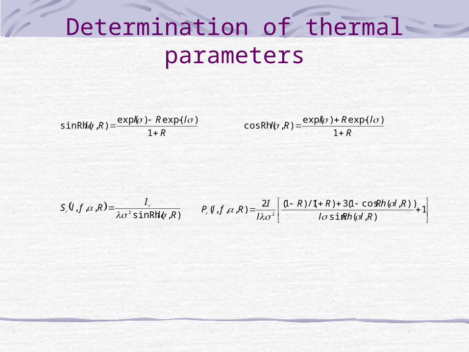
Determination of thermal parameters
R
lRlRl
1
)exp()exp(),sinRh(
R
lRlRl
1
)exp()exp(),cosRh(
),sinRh(
,,,2 Rl
IRflS r
r
1
),(sin
)),(cos1(3)1/()1(2),,,(
2 RlRhl
RlRhRR
l
IRflPr
Determination of thermal parameters
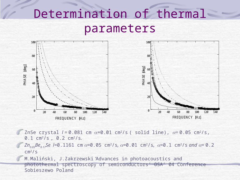
ZnSe crystal l = 0.081 cm =0.01 cm2/s ( solid line), = 0.05 cm2/s, 0.1 cm2/s , 0.2 cm2/s.Zn0.83Be0.17Se l=0.1161 cm =0.05 cm2/s, =0.01 cm2/s, =0.1 cm2/s and = 0.2 cm2/sM.Maliński, J.Zakrzewski ‘Advances in photoacoustics and photothermal spectroscopy of semiconductors’ OSA’ 04 Conference Sobieszewo Poland
20 40 60 80 100 120 140 0
20
40
60
80
100
FREQUENCY [Hz]
PHA
SE [
deg]
20 40 60 80 100 120 140 0
20
40
60
80
100
FREQUENCY [Hz]
PHA
SE [d
eg]
Determination of thermal parameters
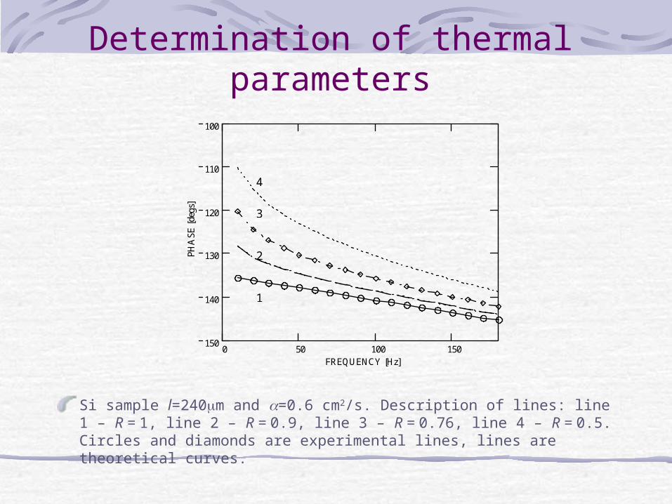
Si sample l=240m and =0.6 cm2/s. Description of lines: line 1 – R = 1, line 2 – R = 0.9, line 3 – R = 0.76, line 4 – R = 0.5. Circles and diamonds are experimental lines, lines are theoretical curves.
0 50 100 150 150
140
130
120
110
100
FREQUENCY [Hz]
PHA
SE [
degs
]
1
2
3
4
Determination of thermal parameters
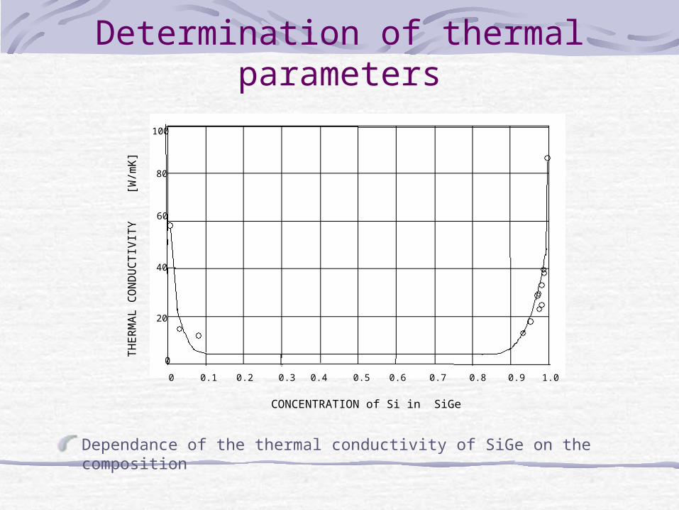
Dependance of the thermal conductivity of SiGe on the composition
CONCENTRATION of Si in SiGe
0 0.1 0.2 0.3 0.4 0.5 0.6 0.7 0.8 0.9 1.0
100
80
60
40
20
0
TH
ER
MA
L C
ON
DU
CT
IVIT
Y
[W
/mK
]
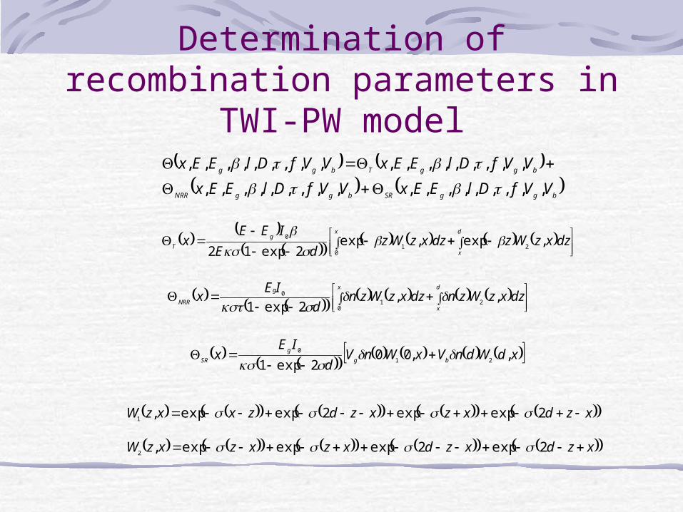
Determination of recombination parameters in TWI-PW model
bggSRbggNRR
bggTbgg
VVfDlEExVVfDlEEx
VVfDlEExVVfDlEEx
,,,,,,,,,,,,,,,,,,
,,,,,,,,,,,,,,,,,,
d
x
xg
T dzxzWzdzxzWzdE
IEEx ,exp,exp
2exp12 20
1
0
d
x
xg
NRR dzxzWzndzxzWznd
IEx ,,
2exp1 20
1
0
xdWdnVxWnVd
IEx bg
g
SR ,,002exp1 21
0
xzdxzxzdzxxzW 2expexp2expexp,1
xzdxzdxzxzxzW 2exp2expexpexp,2
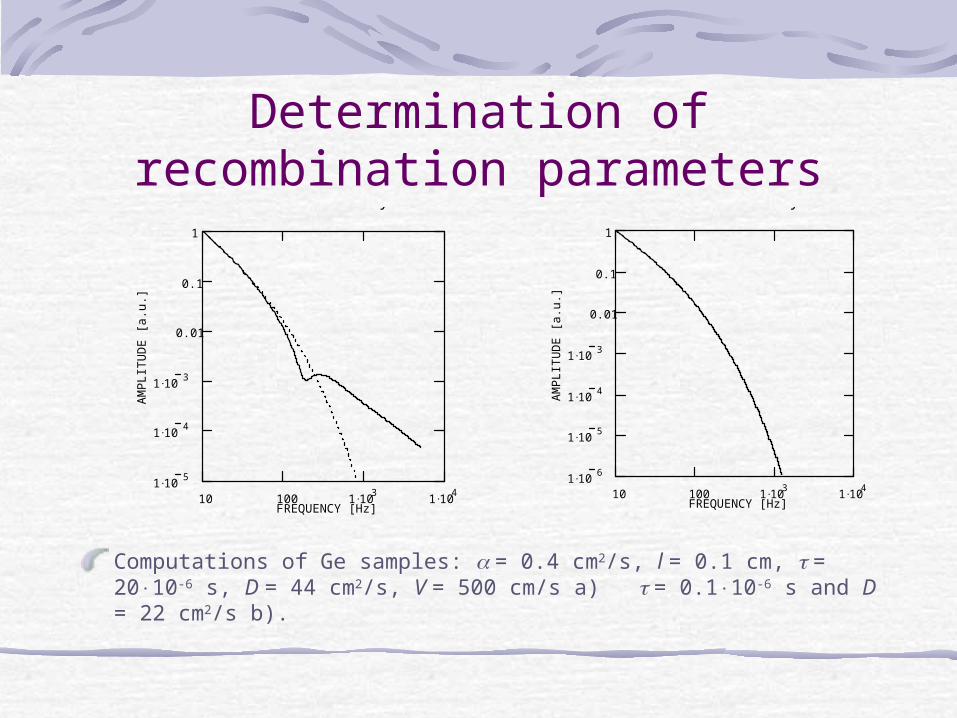
Determination of recombination parameters
Computations of Ge samples: = 0.4 cm2/s, l = 0.1 cm, = 2010-6 s, D = 44 cm2/s, V = 500 cm/s a) = 0.110-6 s and D = 22 cm2/s b).
Rys 1
10 100 1 103
1 104
1 105
1 104
1 103
0.01
0.1
1
FREQUENCY [Hz]
AM
PL
ITU
DE
[a.
u.]
Rys 1
10 100 1 103
1 104
1 106
1 105
1 104
1 103
0.01
0.1
1
FREQUENCY [Hz]
AM
PL
ITU
DE
[a.
u.]
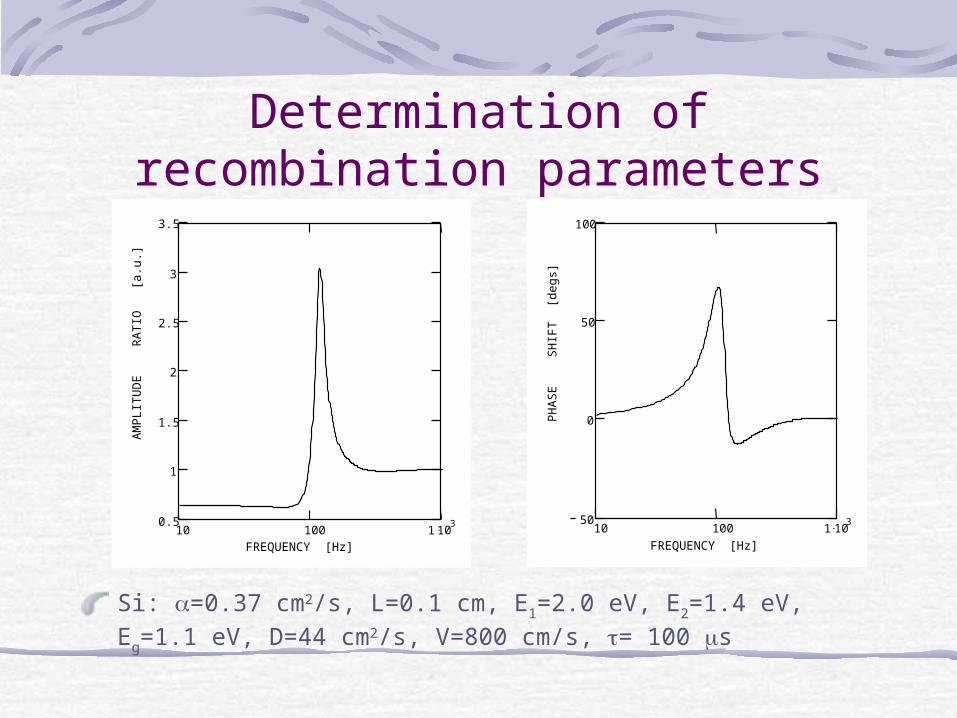
Determination of recombination parameters
Si: =0.37 cm2/s, L=0.1 cm, E1=2.0 eV, E2=1.4 eV, Eg=1.1 eV, D=44 cm2/s, V=800 cm/s, = 100 s
10 100 1 1030.5
1
1.5
2
2.5
3
3.5
FREQUENCY [Hz]
AM
PL
ITU
DE
R
AT
IO
[a.u
.]
10 100 1 10350
0
50
100
FREQUENCY [Hz]P
HA
SE
S
HIF
T [
degs
]
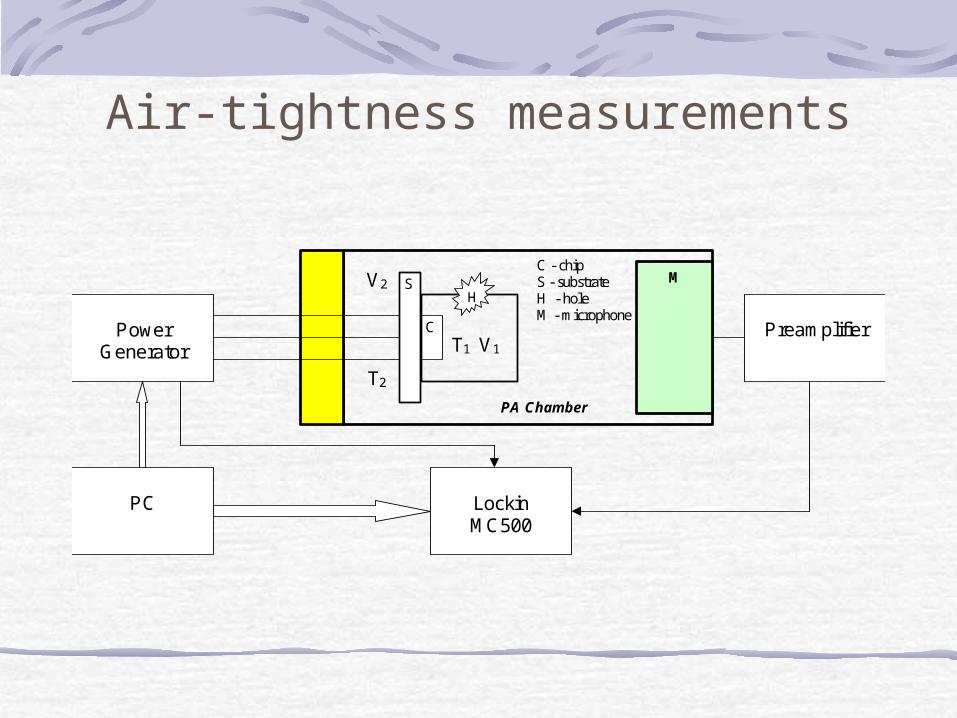
Air-tightness measurements
S
C
T2
T1 V1
V2 M C - chip S - substrate H - hole M - microphone
H
Power Generator
Preamplifier
PC
Lockin MC500
PA Chamber
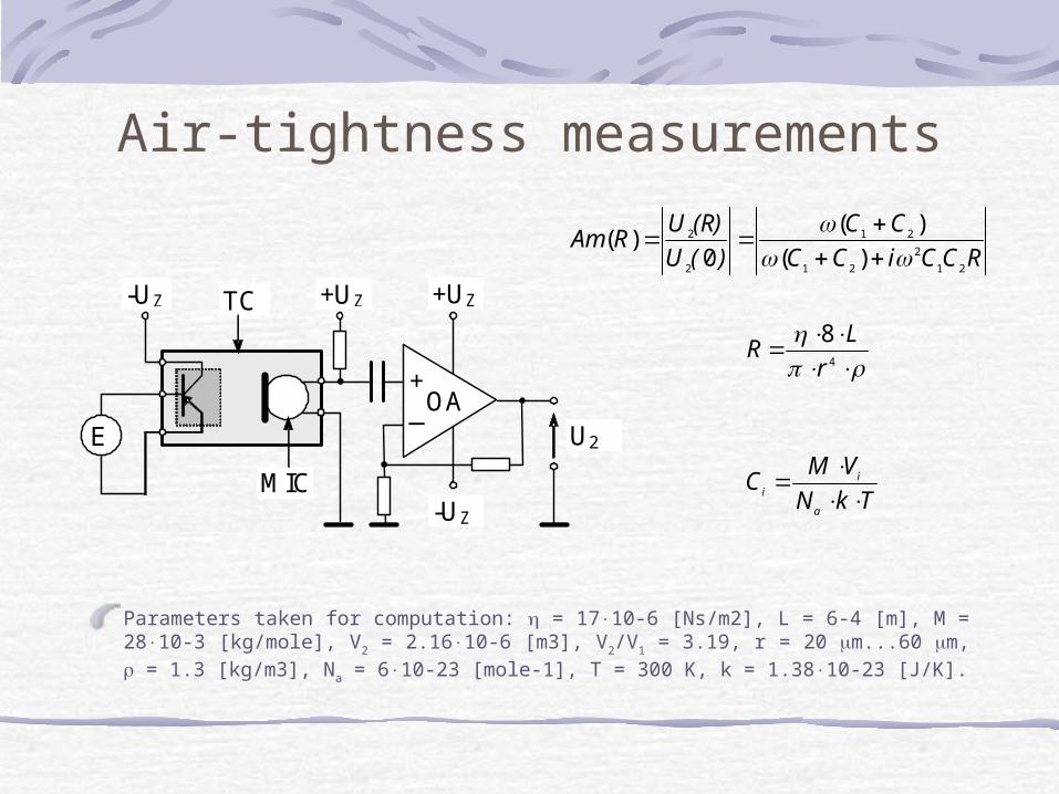
Air-tightness measurements
Parameters taken for computation: = 1710-6 [Ns/m2], L = 6-4 [m], M = 2810-3 [kg/mole], V2 = 2.1610-6 [m3], V2/V1 = 3.19, r = 20 m...60 m, = 1.3 [kg/m3], Na = 610-23 [mole-1], T = 300 K, k = 1.3810-23 [J/K].
E
-UZ +UZ +UZ
+ _
-UZ
U2
TC
MIC
OA
RCCiCC
CC
)(U
(R)URAm
21
2
21
21
2
2
)(
)(
0)(
4
8
r
LR
TkN
VMC
a
i
i
Air-tightness measurements
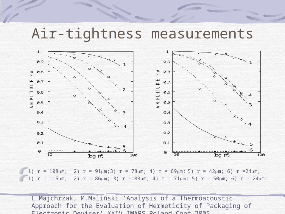
1) r = 108m; 2) r = 91m;3) r = 78m; 4) r = 69m; 5) r = 42m; 6) r =24m;1) r = 115m; 2) r = 86m; 3) r = 83m; 4) r = 71m; 5) r = 50m; 6) r = 24m;
10 100 log (f)
1
2
4
5
3
6
0
0.1
0.2
0.3
0.4
0.5
0.6
0.7
0.8
0.9
1
AM
PL
ITU
DE
R
AT
IO
[1]
10 100 0
0.1
0.2
0.3
0.4
0.5
0.6
0.7
0.8
0.9
1
log (f) A
MP
LIT
UD
E
RA
TIO
[1
]
5
4
3
1
2
6
L.Majchrzak, M.Maliński ‘Analysis of a Thermoacoustic Approach for the Evaluation of Hermeticity of Packaging of Electronic Devices’ XXIV IMAPS Poland Conf 2005
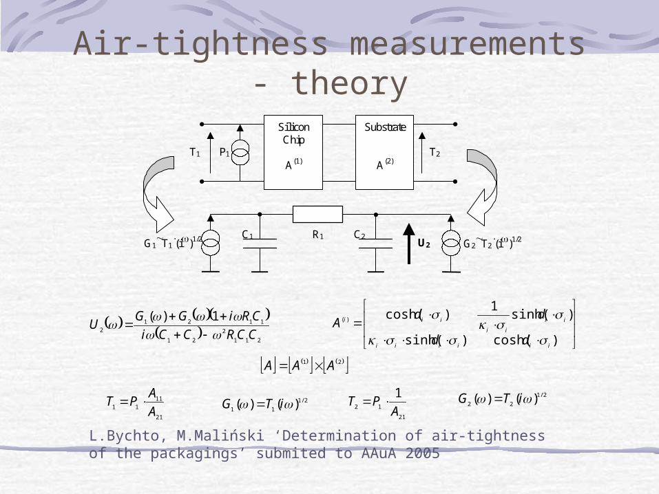
Air-tightness measurements - theory
211
2
21
1121
2
1)(
CCRCCi
CRiGGU
21
11
11 A
APT
21
12
1
APT 2/1
11 )()( iTG 2/1
22 )()( iTG
)cosh()sinh(
)sinh(1
)cosh()(
iiiiii
ii
ii
iii
dd
ddA
Silicon Chip
A(1)
Substrate
A(2) T1 P1 T2
G1T1
(i)1/2 G2
T2(i)1/2
C1 C2 R1 U2
21 AAA
L.Bychto, M.Maliński ‘Determination of air-tightness of the packagings’ submited to AAuA 2005
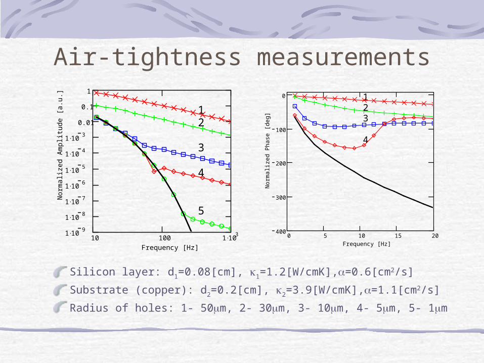
Air-tightness measurements
Silicon layer: d1=0.08[cm], 1=1.2[W/cmK],=0.6[cm2/s]
Substrate (copper): d2=0.2[cm], 2=3.9[W/cmK],=1.1[cm2/s]
Radius of holes: 1- 50m, 2- 30m, 3- 10m, 4- 5m, 5- 1m
10 100 1 1031 10
9
1 108
1 107
1 106
1 105
1 104
1 103
0.01
0.1
1
Frequency [Hz]
Nor
mal
ized
Am
plit
ude
[a.u
.]
1 2
3
4
5
0 5 10 15 20400
300
200
100
0
Frequency [Hz]
Nor
mal
ized
Pha
se [
deg]
1 2 3
4
Conclusions
Frequency FA characteristics are a useful tool bringing information about:Multilayer optically opaque systemsOptically semitransparent systemsThermal parametersRecombination parameters of carriersAir-tightness of packagings

Thank You for Your attention