FREQUENCY ASSIGNMENT REQUIREMENTS FOR THE LAND MOBILE SERVICE
38
RALI : LM 8 DATE OF EFFECT : 4/12/2000 Sequence Number : 160 Radiocommunications Assignment and Licensing Instruction AUSTRALIAN COMMUNICATIONS AUTHORITY RADIOFREQUENCY PLANNING GROUP CANBERRA FREQUENCY ASSIGNMENT REQUIREMENTS FOR THE LAND MOBILE SERVICE
Transcript of FREQUENCY ASSIGNMENT REQUIREMENTS FOR THE LAND MOBILE SERVICE

RALI : LM 8
DATE OF EFFECT : 4/12/2000
Sequence Number : 160
Radiocommunications Assignment and Licensing Instruction
AUSTRALIAN COMMUNICATIONS AUTHORITY
RADIOFREQUENCY PLANNING GROUP
CANBERRA
FREQUENCY ASSIGNMENT REQUIREMENTSFOR THE
LAND MOBILE SERVICE

RADIOCOMMUNICATIONS ASSIGNMENT AND LICENSINGINSTRUCTIONS
DISCLAIMER
The Australian Communications Authority (ACA) advises that these instructions reflect thecurrent policies of the ACA.
Prospective applicants for licences should, however, on their own responsibility, takewhatever steps necessary to ensure that they have access to appropriate technical or otherspecialist advice independently of the ACA concerning their applications, the operation ofradiocommunications equipment and services, or any other matters relevant to the operationof transmitters and services under the licences in question.
The policies of the ACA, and the laws of the Commonwealth, may change from time to time,and prospective licensees should ensure that they have informed themselves of the currentpolicies of the ACA and of any relevant legislation. Furthermore, prospective applicants forlicences should not rely on statements made in these instructions about the policies that maybe followed by other authorities, nor about the effect of legislation.
Radiocommunications Assignment and Licensing Instructions are subject to periodic reviewand are amended as necessary. To keep abreast of developments, it is important that usersensure that they are in possession of the latest edition.
No liability is or will be accepted by the Minister for Communications, the InformationEconomy and the Arts, the ACA, the Commonwealth of Australia, or its officers, servants oragents for any loss suffered, whether arising directly or indirectly, due to reliance on theaccuracy or contents of these instructions.
Suggestions for improvements to Radiocommunications Assignment and Licensing Instructionsmay be addressed to the ACA at PO Box 78, Belconnen, ACT, 2616. It would be appreciated ifnotification to the ACA of any inaccuracy or ambiguity found, be made without delay in orderthat the matter may be investigated and appropriate action taken.

Table of Contents
FREQUENCY ASSIGNMENT REQUIREMENTS FOR THE LAND MOBILE SERVICE................................................................ 11.0 Purpose ............................................................................................................................................................. 12.0 Current Applicability......................................................................................................................................... 13.0 Service Description ........................................................................................................................................... 14.0 Service Model.................................................................................................................................................... 2
4.1 LMRS Service Model Description...................................................................................................................................34.2 LPMRS Service Model Description ................................................................................................................................5
5.0 Frequency Assignment Policy ........................................................................................................................... 75.1 Spectrum and Channelling Arrangements .......................................................................................................................75.2 Assignment Strategy ........................................................................................................................................................75.3 Supplementary Transmitters ............................................................................................................................................85.4 Trunked Systems..............................................................................................................................................................8
5.4.1 VHF High Band Trunking Groups and Sub-segments ............................................................................................85.4.2 400 MHz Trunking Groups .....................................................................................................................................85.4.3 800 MHz Trunking Groups .....................................................................................................................................8
5.5 Single Frequency Systems ................................................................................................................................................96.0 Frequency Coordination Procedure ................................................................................................................. 9
6.1 Overview .........................................................................................................................................................................96.2 Site Selection ...................................................................................................................................................................96.3 Frequency-Distance Constraints ....................................................................................................................................10
6.3.1 Cull for Frequency-Distance Constraints ..............................................................................................................106.3.2 Application of Frequency-Distance Constraints....................................................................................................10
6.4 Initial Frequency Selection ............................................................................................................................................106.5 Intermodulation Checks.................................................................................................................................................10
6.5.1 Introduction ...........................................................................................................................................................106.5.2 Cull for Intermodulation Checks ...........................................................................................................................116.5.3 Performance of Intermodulation Checks ...............................................................................................................116.5.4 Inter-Service Intermodulation Checks ...................................................................................................................12
6.6 The Frequency Assignment ...........................................................................................................................................126.7 Frequency Assignment Procedure - Trunked Systems...................................................................................................126.8 Local Environment ........................................................................................................................................................13
RALI Authorisation ................................................................................................................................................ 13Bibliography........................................................................................................................................................... 14Annex A - Propagation Loss Models...................................................................................................................... 15
A1. Modified Longley-Rice Model .....................................................................................................................................15A2. Modified Hata Model....................................................................................................................................................16
Annex B - Block, Group and Channel Allocations for Trunking Channels............................................................ 17B1. Block and Group Allocations for VHF High Band Trunking Channels........................................................................17B2. Channel Allocations for VHF High Band Trunking Channels......................................................................................19B3. Block, Group and Channel Structure for the 400 MHz Trunking Band........................................................................21B4. Block, Group and Channel Structure for the 800 MHz Trunking Band........................................................................23
Annex C - Frequency-Distance Constraints........................................................................................................... 25C1. Cull Limits Applicable to Frequency-Distance Constraints ..........................................................................................25C2. Frequency-Distance Constraints for Single Frequency LMRS in the VHF Mid and High Bands ................................26C3. Frequency-Distance Constraints for Single Frequency LMRS in the 400 MHz Band ..................................................27C4. Frequency-Distance Constraints for Single Frequency LPMRS in the 400 MHz Band................................................28C5. Frequency-Distance Constraints for Two Frequency LMRS in the VHF Mid and High Bands ...................................29C6. Frequency-Distance Constraints for Two Frequency LMRS in the 400 MHz Band .....................................................30C7. Frequency-Distance Constraints for Two Frequency LPMRS in the 400 MHz Band...................................................31C8. Frequency-Distance Constraints for Trunked Services in the 800 MHz Trunking Band ..............................................31
Annex D - Intermodulation Checks ........................................................................................................................ 32D1. Cull Limits Applicable to Intermodulation Checks ......................................................................................................32D2. Frequency Offset from Victim Receiver Within which an Intermodulation ‘Hit’ is Deemed to Occur ........................33D3. Expressions for Evaluating Intermodulation Interference.............................................................................................33D4. Parameter Values Applicable to Intermodulation Checks.............................................................................................34
Annex E - Inter-service Coordination .................................................................................................................... 35E1. VHF Mid and High Assignments Adjacent to Television Channels 2, 3 and 6.............................................................35E2. 400 MHz Assignments in the Vicinity of Wideband Fixed Services ............................................................................35E3. 400 MHz Assignments Within 675 km of Jervis Bay ...................................................................................................35E4. 800 MHz Trunking Assignments Adjacent to UHF Television Channel 69 .................................................................35E5. 800 MHz Trunking Assignments Adjacent to Spectrum Licensed Services .................................................................35

LM 8 December 2000
1
Frequency Assignment Requirements for the Land Mobile Service
1.0 Purpose
The purpose of this Radiocommunications Assignment and Licensing Instruction (RALI) is toprovide advice on frequency assignment policy and coordination procedures for single and twofrequency land mobile systems employing angle and digital modulation methods.
This RALI replaces RALI LM 8, dated 6 April 1998, Sequence Number 129 (113).
The information in this document reflects the Australian Communications Authority’s statementof current policy in relation to frequency assignment requirements for the land mobile service. Inmaking decisions, Australian Communications Authority (ACA) and accredited frequencyassigners should take all relevant factors into account and decide each case on its merits. If anissue related to this document appears to fall outside the enunciated policy, please consult theManager, Spectrum Planning Team, Central Office.
2.0 Current Applicability
This RALI currently applies to angle and digital modulated:
• single and two frequency systems in the VHF Mid and High bands1 using 12.5 kHzchannelling;
• single and two frequency systems in the 400 MHz band2 using 12.5 and 25 kHzchannelling; and
• 800 MHz trunked systems3 using 25 kHz channelling.
It is intended that this RALI will be expanded to cover single and two frequency systems in theVHF Mid and High bands using 25 kHz channelling, and single and two frequency systems inthe VHF-low frequency band, as the assignment requirements are able to be consolidated.
3.0 Service Description
Radiocommunications systems operating in the land-mobile service (LMS) are typically used tocommunicate information between a controlling station and vehicular mobile or personal stationsoften for, but not limited to, the purposes of dispatch activities related to the performance of abusiness or other organisational activity.
In the case of two frequency systems, communication usually occurs between a remote controlstation (RCS) and mobile stations via a centrally located land station (often referred to as a ‘base’station or repeater) which is located at a high site in order to serve the surrounding area. Thebase station receives transmissions on its ‘base receive’ frequency from the RCS or any mobile
1 These frequency bands are defined in the VHF Mid Band Frequency Band Plan (70 to 87.5 MHz), Statutory Rules 1991 No. 355, and theVHF High Band Frequency Band Plan (148 to 174 MHz), Statutory Rules 1991 No. 354.
2 The 400 MHz band (403 to 520 MHz) is defined in RALI MS 22 [3].
3 The frequency band for the 800 MHz trunked land mobile service is defined in the 900 MHz Band Plan, Statutory Rules 1992 No.47.
LM 8 December 2000
2
within the notional service area and subsequently repeats those transmissions on its ‘basetransmit’ frequency for reception by any other mobile (or the RCS) within the notional servicearea.
In single frequency systems, the controlling station typically is the ‘base’ station and is at thecentre of the notional service area, although in some cases the controlling station is linked(sometimes by land line) to a ‘base’ station at a high site. All communications occur on the onefrequency.
Trunked land mobile systems (TLMS) are functionally similar to the two frequency non-trunkedsystems described above. However, in a trunked system, a group of channels at the base stationsite is time-shared between a large number of users so that the channels can be used moreefficiently.
Low-power land mobile radio systems (LPMRS) are functionally similar to the systemsdescribed above but have a much smaller coverage area. They are located primarily inhigh-density areas and have greater frequency re-use. LPMRS are generally single frequencysystems but may be two frequency systems and are used typically in crane control andambulatory applications.
From an interference management perspective, an LMS has the following characteristics:
• it has a central fixed land station (generally referred to as a base station); in practice this isthe controlling station in a single frequency system and the repeater in a two frequencysystem, and is commonly located at a high site;
• the base station serves a number of mobile/personal mobile stations, distributed randomlythroughout the service area;
• in the case of a two frequency system, the controlling station (RCS) is treated as a ‘fixedmobile’ in the service area; and
• communication occurs mostly between mobiles and the controlling station (via a repeaterin a two frequency system) although, in some cases, direct mobile-to-mobile or personalmobile-to-personal mobile communication may occur.
4.0 Service Model
The purpose of the service model is to define a set of characteristics for the LMS that will resultin a specified ‘target’ grade of service for land mobile systems. There are two service modelsdefined; one for large coverage applications (LMRS) and the other for small coverageapplications (LPMRS).
The target grade of service (TGS) is defined as a signal quality of 12 dB SINAD4 for voicesystems or a bit error rate of 10-2 for data systems at the receiver output for a 5 dB5 ratio ofwanted to unwanted signals at the receiver RF input terminal. The model defines values for a setof parameters (at the inter-system, intra-system and equipment levels) that, when satisfied, willachieve the TGS for LMS receivers at 90% of locations within the notional service area of a landmobile system. The model also manages interference to acceptable levels, planned not to exceed1% of the time in any 1 hour period.
4 SINAD - the ratio of (signal + noise + distortion) to (noise + distortion).
5 This value is assumed in a static environment. In a faded environment, the median wanted to unwanted ratio is assumed to be 15 dB. Thisassumes Rayleigh fading and a lognormal (6 dB variance) location variability.
LM 8 December 2000
3
Sections 5 and 6 of this RALI detail the frequency assignment policy and coordinationprocedures for land mobile systems which use, as their basis, the service model as described inthis section.
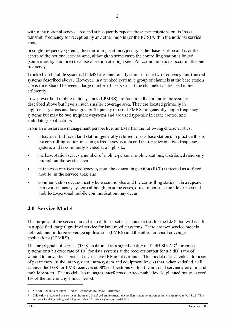
4.1 LMRS Service Model Description
40 km notionalservice area
100 km reuse distance (two-freq)140 km reuse distance (single-freq)
Base Station:• EIRP = 83 W• effective antenna height = 200 m
Mobile Station:• EIRP = 41 W
40 km notional service area
• antenna height = 1.5 m
Figure 1 - LMRS Service Model
Key features of the service model are:
• the radiated power is limited to an equivalent isotropically radiated power (EIRP) for allstations as follows;
− 83 watts (W) for base stations (50 W into a 2.15 dBi dipole antenna);
− 41 W for mobile stations (25 W into a 2.15 dBi λ/4 monopole antenna);
− 41 W for supplementary transmitters (25 W into a 2.15 dBi λ/4 monopole antenna);
− 20 W maximum for RCSs (1 W maximum into a 13 dBi yagi antenna);
− 8.3 W for personal mobile stations (5 W into a 2.15 dBi λ/4 monopole antenna);
• an assumed base station effective antenna height of 200 metres above surrounding terrainand a mobile antenna height of 1.5 metres above ground level;
• assumed receiver usable sensitivity levels (refer to Annex D, Table D3, of this RALI);

LM 8 December 2000
4
• the use of a modified Longley-Rice model (base-to-base) and the modified Hata model(base-to-mobile) for propagation loss calculations associated with frequency-distanceconstraints (refer to Annex A of this RALI);
• the use of free space loss plus 10 dB for intermodulation propagation loss calculationsassociated with cull distances for intermodulation checks;
• a notional service area radius of 40 km;
• a notional antenna for base station receivers, assumed to be a vertically polarised dipolearray with a maximum antenna gain in any direction of 2 dBi at VHF and 6 dBi at UHF(Note that these figures include cable and combiner loss, but exclude cavity filter loss);
• an assumed adjacent channel isolation (ACI) of 50 dB (ACI describes the isolationachieved between systems operating on adjacent channels, as a consequence of transmitteradjacent channel power and receiver adjacent channel selectivity performance);
• an assumed transmitter adjacent channel power not exceeding -16 dBm;
• a co-channel re-use distance of 140 km and 100 km between single and two-frequency basestations respectively;
• frequency coordination that is performed for base stations only (specific levels ofprotection for mobiles and RCSs are intrinsic to the service model);
• assumed maximum levels of spurious emissions, including broadband noise radiated froma transmitter;
• an assumed receiver blocking performance of 90 dB above the receiver usable sensitivitylevels specified in Annex D, Table D3, of this RALI;
• an assumed receiver Intermediate Frequency (IF) bandwidth of 11 kHz at the 6 dB pointsfor 12.5 kHz channelled equipment and 16 kHz at the 6 dB points for 25 kHz channelledequipment;
• an assumption that additional RF selectivity, equivalent to that achieved by a 6-inch cavityfilter, is installed on base station receivers, to reduce their susceptibility to interferencefrom site-based intermodulation products (refer to Annex D, Table D3, of this RALI);
• a limit on RCS transmitter output power to a maximum of 1 watt, which requires that adirectional antenna be used to achieve the EIRP limit referred to above. The modelpresumes that the EIRP is limited to the minimum necessary to achieve a signal level15 dB above the base station receiver’s 12 dB SINAD sensitivity level at its input terminal.These limits minimise the potential for interference between the RCS and an adjacentco-channel base station;
• specific requirements for RCSs to minimise their potential for causing intermodulationinterference in areas having a relatively high concentration of transmitters and receivers.The model presumes the following requirements for RCSs located in central businessdistricts:
− the height of an RCS antenna does not exceed 30 metres above ground level; and
LM 8 December 2000
5
− a 20 dB in-line attenuator6 is fitted between the output of an RCS transmitter and itsassociated antenna;
• the assumption that services are co-sited when they are located within 200 metres of eachother;
• the inclusion of co-channelled transmitters (supplementary transmitters) to improve theservice reliability within, but not outside, the notional service area; and
• the assumption that 800 MHz trunked equipment is approved to Federal CommunicationsCommission (FCC) Rules Part 90.
Note that equipment meeting the Australian radiocommunications equipment standard(s)relevant to operation in the LMS will also meet the level of performance assumed above foradjacent channel isolation, receiver sensitivity, and transmitter spurious and out-of-bandemissions.
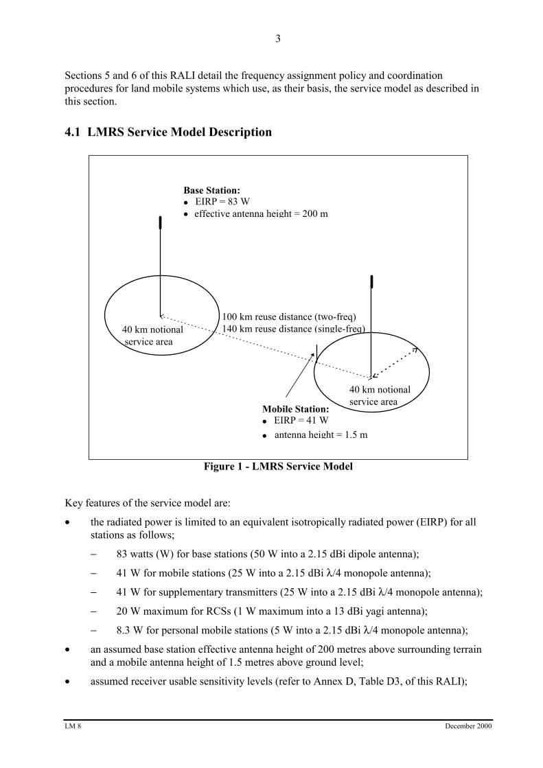
4.2 LPMRS Service Model Description
2 km service area
10 km reuse distance
Base Station:• EIRP = 8.3 watts• effective antenna height = 10 m
Mobile Station:• EIRP = 8.3 W
2 km service area
• antenna height = 1.5 m
Figure 2 - LPMRS Service Model
6 The model allows for the use of other devices such as isolators or feed-forward amplifiers which give intermodulation performanceequivalent to or better than that achieved by a 20 dB in-line attenuator.

LM 8 December 2000
6
Key features of the LPMRS service model are:
• the radiated power is limited to an EIRP for all stations as follows;
− 8.3 W for base stations (5 W into a 2.15 dBi dipole antenna);
− 8.3 W for mobile stations (5 W into a 2.15 dBi λ/4 monopole antenna);
− 8.3 W for personal mobile stations (5 W into a 2.15 dBi λ/4 monopole antenna);
• base station effective antenna height of 10 metres above surrounding terrain and a mobileantenna height of 1.5 metres above ground level;
• assumed receiver usable sensitivity levels (refer to Annex D, Table D3, of this RALI);
• the use of the modified Hata model for base-to-base and base-to-mobile propagation losscalculations associated with frequency-distance constraints (refer to Annex A of thisRALI);
• the use of free space loss plus 10 dB for intermodulation propagation loss calculationsassociated with cull distances for intermodulation checks;
• a notional service area radius of 2 km;
• a notional antenna for base station receivers, assumed to be a vertically polarised dipolearray with a maximum antenna gain in any direction of 2 dBi at VHF and 6 dBi at UHF(Note that these figures include cable and combiner loss, but exclude cavity filter loss);
• a notional antenna for base station receivers, assumed to be a vertically polarised dipolearray with a maximum antenna gain in any direction of 6 dBi (including cable andcombiner loss, excluding cavity filter loss);
• an assumed adjacent channel isolation (ACI) of 50 dB;
• an assumed transmitter adjacent channel power not exceeding -16 dBm;
• a co-channel re-use distance of 10 km between base stations;
• frequency coordination that is performed for base stations only (specific levels ofprotection for mobiles and RCSs are intrinsic to the service model);
• assumed maximum levels of spurious emissions, including broadband noise radiated froma transmitter;
• an assumed receiver blocking performance of 90 dB above the receiver sensitivity levelsspecified in Annex D, Table D3, of this RALI;
• an assumed receiver IF bandwidth of 11 kHz at the 6 dB points for 12.5 kHz channelledequipment and 16 kHz at the 6 dB points for 25 kHz channelled equipment;
• an assumption that additional RF selectivity, equivalent to that achieved by a 6 inch cavityfilter, is installed on base station receivers to reduce their susceptibility to interference fromsite-based intermodulation products;
• the assumption that services are co-sited when they are located within 200 metres of eachother; and
• specific requirements for crane control applications using LPMRS. The transmitter outputpower is assumed to be a maximum of 1 watt. The crane antenna is assumed to have amaximum beamwidth of 80 degrees with down tilt.

LM 8 December 2000
7
Note that equipment meeting the Australian radiocommunications equipment standard(s)relevant to operation in the LMS will also meet the level of performance assumed above foradjacent channel isolation, receiver sensitivity, and transmitter spurious and out-of-bandemissions.
5.0 Frequency Assignment Policy
Frequency assignment must take into consideration both inter-service and intra-servicerequirements consistent with the assignment philosophy promulgated in RALI MS 2.Consideration should be given also to the issue of spectrum denial at and around popular (prime)radiocommunications sites7.
Successful management of interference in the LMS requires that all stations operating in theservice (mobile, base and RCS) comply with specific technical constraints.
Intra-service constraints form an essential element of the service model upon which frequencyassignment requirements are based, and are detailed in the following paragraphs. Theintra-service frequency coordination procedure is also part of this policy framework and isoutlined in section 6 of this RALI.
Inter-service coordination of land-mobile services with other radiocommunications services areaddressed, in some cases, by specific RALIs. Annex E lists inter-service coordinationrequirements prepared by the ACA. In other cases, ITU-R Recommendations may exist.However, because of the diversity and complexity of sharing situations which may arise, it is notpossible to provide rigorous and explicit procedures covering all inter-service coordinationrequirements. In these cases, coordination should be performed in accordance with goodengineering practice based on fundamental interference mitigation principles.
5.1 Spectrum and Channelling Arrangements
Spectrum and channelling arrangements are specified in the band plans referenced at section 2 ofthis RALI. Trunked systems may operate in ‘non-trunked’ two-frequency spectrum; howeverspectrum allocated in the relevant band plans for trunking should not be assigned to non-trunkedsystems.
As well as complying with the channelling arrangements specified in the relevant band plans,assignments to a TLMS at any given site should be in accordance with the Block and Grouparrangements tabulated at Annex B of this RALI. These arrangements have been established tominimise the occurrence of site-based intermodulation interference.
5.2 Assignment Strategy
The procedure for assigning land mobile base station frequencies is based on a strategy ofhorizontal loading and maximum isolation between assigned services. Under this strategy,frequencies that pass interference checks by the greatest margin are assigned. This approachmaximises the isolation between systems which typically achieve a grade of service well inexcess of the TGS; the actual grade of service and reliability will reduce, over time, towards the
7 Spectrum Planning report 25/92 “Furthering Productivity of Prime Sites – Advice to Site Managers” contains useful information that is
relevant to the issue of spectrum denial at and around popular radiocommunications sites.

LM 8 December 2000
8
TGS as the spectrum becomes more congested.
5.3 Supplementary Transmitters
A supplementary transmitter is a transmitter intended to improve the service reliability within a40 km radius of the ‘parent’ base station. A supplementary transmitter does not requirefrequency coordination. However, it must not cause interference to other radiocommunicationservices, and no additional level of protection from interference to a related supplementaryreceiver (above that offered to a mobile receiver) is provided.
Note that a transmitter which extends coverage beyond a 40 km radius of the ‘parent’ basestation is not a supplementary transmitter; it is another base station and must be frequencycoordinated in the same manner as any other base station.
5.4 Trunked Systems
5.4.1 VHF High Band Trunking Groups and Sub-segments
The basic trunking assignment unit is the group, which consists of five channels (refer toAnnex B1 of this RALI). The 120 channels in each sub-segment are arranged into 12 blocks,each consisting of two groups of five channels. Channels should be assigned at any given site ingroups of five, as shown at Annex B1 of this RALI, wherever possible.
Note that the VHF High Band trunking segments are divided into two equal sub-segments, A andB (refer to Annex B1 of this RALI), in order to minimise the potential for site-based interferencedue to 3rd and 5th order intermodulation products. At any one site, assignments may be madefrom either sub-segment, A or B, but not both. Sites at which frequencies from differentsub-segments are used must be separated by at least 200 metres.
5.4.2 400 MHz Trunking Groups
The basic trunking assignment unit is the group, which consists of five channels (refer toAnnex B3 of this RALI). Four groups comprise a block. The 200 channels are arranged into 10blocks, each consisting of four groups of five channels. Channels should be assigned at anygiven site in sets of five, as shown at Annex B3 of this RALI, wherever possible.
5.4.3 800 MHz Trunking Groups
The basic trunking assignment unit is the group, which consists of five channels (refer to AnnexB4 of this RALI). Four groups comprise a block. The 200 channels are arranged into 10 blocks,each consisting of four groups of five channels. Channels should be assigned at any given site ingroups of five, as shown at Annex B4 of this RALI, wherever possible.

LM 8 December 2000
9
5.5 Single Frequency Systems
Segments for single frequency assignments are specified in the band plans referenced at section 2of this RALI.
As noted in the 400 MHz band plan (RALI MS22), single frequency segments in the 400 MHzband are intended primarily for the assignment of low power (8.3 W EIRP) land mobileservices8. Assignments to single frequency high power (83 W EIRP) land mobile services may,however, be made in these segments if required; as in the case of all instances of single frequencyhigh power assignments an important consideration is the amount of spectrum denial at or nearprime sites.
6.0 Frequency Coordination Procedure
Frequency coordination is performed only for base stations in the LMS; interference protectionfor mobiles and RCSs is intrinsic to the service model described in section 4 of this RALI.
The following sections detail a coordination procedure that may be applied for frequencyassignment of LMS base stations.
Alternative frequency coordination procedures may be used provided that they produceequivalent results, that is, the target grade of service is achieved at 90% of locations within thenotional service area (refer to section 4 of this RALI).
Note that automation of the coordination procedure (by means of an appropriate softwareapplication) is highly desirable, particularly when coordinating services in areas of high spectrumoccupancy.
6.1 Overview
The general procedure for frequency coordination and assignment of land mobile base stationstakes the following form:
• site selection;
• application of frequency-distance constraint checks;
• initial frequency selection;
• intermodulation checks; and
• the frequency assignment.
The following sections describe the above steps in more detail.
6.2 Site Selection
Initial site selection is likely to be based on the client’s needs, but may need to be altereddependent on the outcome of the frequency coordination process outlined below.
8 For background information see Spectrum Planning Report SP 2/00, “Review of the ACA Policy on the Assignment of Single Frequency High
Power and Low Power Mobile Services in the 400 MHz Band”.

LM 8 December 2000
10
6.3 Frequency-Distance Constraints
6.3.1 Cull for Frequency-Distance Constraints
Perform a cull (ie, produce a list) of existing systems which due to their frequency and distanceseparation from the proposed system have the potential to cause or receive interference throughco-channel emissions, out-of-band emissions, and transmitter broadband noise. The minimumradius and frequency range for this cull are specified at Annex C, Table C1 of this RALI.
6.3.2 Application of Frequency-Distance Constraints
Apply the frequency-distance constraints to assess the potential for interference between theproposed assignment and the systems yielded by the cull. The frequency-distance constraints forsingle frequency and two frequency services are detailed at Annex C of this RALI.
Tables C2, C3.1, C3.2, C4.1 and C4.2 apply whenever a single frequency system (proposed orexisting) requires frequency coordination, or whenever two-frequency systems are to becoordinated with one another and one operates with reverse frequency sense to the other (ie, thetransmit frequency of one equals the receive frequency of the other).
Tables C5, C6, C7 and C8 apply in the situation where both systems to be coordinated (proposedand existing) use two frequency operation, and have the same frequency sense.
6.4 Initial Frequency Selection
Ideally, the channel that passes the frequency-distance constraints by the greatest margin shouldbe selected for subsequent intermodulation checks. Note that for two-frequency systems this willinvolve selection of a pair of frequencies (base transmit and base receive) that each satisfy thefrequency-distance constraints by the greatest possible margin. If however, particular needs ofthe client are best satisfied with a channel passing by a lesser margin, that channel may beselected instead.
6.5 Intermodulation Checks
6.5.1 Introduction
Intermodulation checks are performed for two-signal 3rd order, three-signal 3rd order andtwo-signal 5th order intermodulation.
Transmitter Intermodulation
The proposed transmitter must be evaluated for the potential for its emissions to mix withemissions from other transmitters at the site, to produce 3rd or 5th order intermodulationproducts that are likely to cause interference to the proposed or existing receivers.Mixing of transmitter emissions can occur in passive components (eg, site hardware suchas couplers, isolators or mechanical/structural joints) as well as in non-linear transmitteroutput stages, and can result in intermodulation products that are co-channel with theproposed or existing receivers. As the characteristics of the components in which themixing occurs cannot be known under these circumstances, the criterion for harmfulinterference caused by transmitter intermodulation is simply the occurrence of a ‘hit’between co-sited systems.

LM 8 December 2000
11
Receiver Intermodulation
The proposed receiver, and existing receivers within specified frequency ranges anddistances of the proposed system, must also be evaluated for their potential to receiveinterference due to intermodulation products caused by the mixing of transmitteremissions in proposed and existing receivers. Intermodulation products can be generatedin the rf input stages of receivers if sufficient signal power is applied to drive a stage intoa non-linear condition. Because of this input level dependency, the ‘quality’ of a hit canbe quantified and either noted as having the potential to cause harmful interference, ordiscarded because it does not have a sufficient level to cause harmful interference.
6.5.2 Cull for Intermodulation Checks
Perform a cull of existing systems for which the potential for intermodulation interference mustbe considered. The cull identifies all such systems within defined frequency and distance limitsfrom the proposed system. The radius and frequency range for each required cull is specified inAnnex D, Table D1, of this RALI.
6.5.3 Performance of Intermodulation Checks
Perform checks for intermodulation interference between the selected assignment frequency(both transmit and receive, if they are different) and existing systems yielded by the cull, in themanner described below.
Transmitter Intermodulation
If the operating frequencies of any two co-sited transmitters (including the proposedtransmitter) are contained in the relevant bandplan (eg, the entire VHF Mid or HighBand), and can be algebraically combined in the form shown in Table 1 to produce a 3rdor 5th order intermodulation product within the ‘hit’ range of a co-sited receiver (asdefined in Annex D, Table D2, of this RALI) the proposed frequency should not beassigned.
Frequencies of 3rdOrder Products *
Frequencies of 5thOrder Products *
2f1 - f2 3f1 - 2f2
2f2 - f1 3f2 - 2f1
f1 + f2 - f3
f1 - f2 + f3
* f1 = centre frequency of first co-sited transmitter
f2 = centre frequency of second co-sited transmitter
f3 = centre frequency of third co-sited transmitter
Table 1 - Algebraic expressions for 3rd and 5th order intermodulationproduct frequencies

LM 8 December 2000
12
Receiver Intermodulation
All systems falling within the cull limits specified in Annex D, Table D1, of this RALIare first evaluated for the occurrence of 3rd and 5th order intermodulation product ‘hits’as per Table 1. A ‘hit’ is deemed to occur when an intermodulation product falls withinthe frequency ranges from a receiver specified in Annex D, Table D2, of this RALI.
Once the existence of a ‘hit’ has been confirmed, mathematical expressions (1), (2) and(3) shown at Annex D3 of this RALI are evaluated to determine whether unacceptableinterference would be caused due to receiver intermodulation by assignment of theproposed frequency.
When equations (1), (2) and (3) at Annex D3 of this RALI are satisfied, the level ofintermodulation interference is permissible; conversely, when the equations are notsatisfied the level of interference is considered harmful, and the proposed frequencyshould not be assigned.
If either receiver or transmitter intermodulation checks fail against the selected frequency, selectthe frequency that passed the frequency-distance constraints by the next greatest margin andperform intermodulation checks on that frequency.
Continue to perform intermodulation checks on frequencies passing the frequency-distanceconstraints until an acceptable frequency is found.
6.5.4 Inter-Service Intermodulation Checks
Perform intermodulation checks with other radiocommunication services such as television andFM radio broadcasting and paging systems using the frequency chosen above in section 6.5.3 inthis RALI. If the inter-service intermodulation checks fail, find another acceptable frequency asper the procedure in section 6.5.3 in this RALI and perform inter-service intermodulation checkson that frequency until an acceptable frequency is found.
6.6 The Frequency Assignment
Assign to the proposed system the channel that passes the intermodulation checks and satisfiesthe frequency-distance constraints by the greatest margin consistent with meeting the client’soperating frequency requirements as far as practicable.
6.7 Frequency Assignment Procedure - Trunked Systems
The procedure for frequency coordination and assignment of trunked systems is identical to thatfor conventional two frequency systems; however frequency-distance constraints andintermodulation requirements must be met for all frequencies in the proposed trunking block orgroup at the proposed site (refer to Annex B of this RALI).
Note that intra-service intermodulation checks are not required for 800 MHz trunkingassignments due to the homogeneous nature of the trunking segment and the 45 MHz basetransmit/receive split. Inter-service intermodulation checks should be performed with otherservices such as the UHF television service.

Prepared by Spectrum Planning Team File Ref: X95/1481
CANBERRA 2000
13
6.8 Local Environment
There may be circumstances where the channel selected using the above mentioned procedure isnot the optimal channel to be assigned due to the local environment. Examples are: a largemountain range offering additional propagation loss to/from a service in an adjacent area; atransmitter located on a site at a height much greater than the planning model assumes; or ananomalous propagation mode occurring due to a path over water.
Under such circumstances, modified frequency/distance constraints may be applied provided thatthe target grade of service is achieved at 90% of locations within the notional service area (referto section 4 of this RALI).
RALI Authorisation
Barry MatsonExecutive ManagerRadiofrequency Planning GroupAustralian Communications Authority
LM 8 December 2000
14
Bibliography
1. RALI LM 3: ‘Trunked Land Mobile Services’, Australian Communications Authority.
2. RALI LM 5: ‘Frequency Assignment Procedure for Land Mobile Services Adjacent to TVChannels 2, 3 and 6’, Australian Communications Authority.
3. RALI MS 2: ‘Central Office and Area Offices Licensing and Assignment Responsibilities’,Australian Communications Authority.
4. RALI MS 3: ‘Spectrum Embargoes’, Australian Communications Authority.
5. RALI MS 22: ‘400 MHz Plan’, Australian Communications Authority.
6. RALI FX 5: ‘Narrowband Assignments in the Vicinity of Wideband Fixed Services in the403 - 500 MHz Band’, Australian Communications Authority.
7. ‘Land Mobile Frequency Selection Strategies and Compatibility Criteria used in theFrequency Assignment Subsystem of DOC’s Spectrum Management Information System’,M.J. Whittaker, Digest of Papers, IREECON 85, October 1985.
8. ‘Frequency Assignment Strategies in Australia’, M.J. Whittaker, SMIREE; Journal ofElectrical and Electronics Engineering Australia - IE Aust and IREE Aust, Vol 11 No. 3,September 1991.
9. ‘Determining Necessary Adjacent Channel Isolation and Re-use Distance for aRadiocommunication Service’, M.J. Whittaker, SMIREE; Journal of Electrical andElectronics Engineering Australia - IE Aust and IREE Aust, Vol 10 No. 4, December 1990.
10. ‘Minimisation of Intermodulation Interference in Trunked Land Mobile Systems’,Spectrum Planning Report No. 10/91, Spectrum Management Agency, August 1991.
11. ‘Channel Arrangements for the Trunked Land Mobile Segments of the VHF Mid and HighBand Plans’, Spectrum Planning Report No. 11/91, Spectrum Management AgencyJune 1991.
12. ‘VHF High Band Trunking: Minimum Geographical Separation Between Trunking Sites’,Spectrum Planning Report No. 14/91, Spectrum Management Agency, July 1991.
13. ‘A Guide to the Use of the ITS Irregular Terrain Model in the Area Prediction Mode’, G.A.Hufford, A.G. Longley and W.A. Kissick, NTIA Report 82-100, April 1982.
14. ‘Propagation Data and Prediction Methods for the Terrestrial Land-Mobile Service Usingthe Frequency Range 30 MHz to 3 GHz’, CCIR Report 567-4, ITU, 1990.
15. ‘400 MHz Land-Mobile Frequency Assignment Model’, Spectrum Planning Report No.8/97, Australian Communications Authority, December 1997.
16. ‘Review of the ACA Policy on the Assignment of Single Frequency High Power and LowPower Mobile Services in the 400 MHz Band’, Spectrum Planning Report SP 2/00,Australian Communications Authority, March 2000.
17. ‘Furthering Productivity of Prime Sites – Advice to Site Managers’ Spectrum Planningreport 25/92, Spectrum Management Agency, December 1991.

LM 8 December 2000
15
Annex A - Propagation Loss Models
A1. Modified Longley-Rice Model
A modified version of the Longley-Rice propagation loss model [13] has been used in thecalculation of propagation loss for the determination of frequency-distance constraints appearingin Annex C when the interference path is between two high sites having effective antenna heightsof 200 metres above surrounding terrain. The model has also been used for the determination ofintermodulation parameters appearing in Annex D. For information, parameter values used inthe model are detailed in Table A1 below.
Band Frequency Limits
(MHz)
Distance
(km)
Path Loss
(dB)
VHFMid and High
Bands
70 to 87.5
148 to 174
0 < distance <= 0.006
0.006 < distance <= 40
distance > 40
41
FSL + 10
96 + (0.55 x distance)
400 MHzBand
403 to 5200 < distance <= 0.003
0.003 < distance <= 40
distance > 40
45
FSL + 10
104 + (0.55 xdistance)
800 MHzTrunking Band
820 to 8700 < distance <= 0.003
0.003 < distance <= 55
distance > 55
50
FSL + 10
107 + (0.55 xdistance)
Table A1 - Parameter Values used in the Modified Longley-Rice Propagation Loss Model
Note: 1. distance = spatial separation between antennas
2. FSL = Free Space Loss [in dB]
= 32.5 + 20 log (distance [in km] ) + 20 log (frequency [in MHz] )
3. The model estimates propagation loss to a 90 % confidence level and assumes a terrainirregularity factor of 90 metres [13].

LM 8 December 2000
16
A2. Modified Hata Model
The modified Hata propagation loss model [14] has been used in the calculation of propagationloss for the determination of frequency-distance constraints appearing in Annex C when theinterference path is between a high site and a low site (base to mobile). The modified Hata urbanmodel has been used in the determination of LPMRS base-to-base and base-to-mobileparameters.
The modified Hata model estimates mean propagation loss (50% of locations for 50% of thetime). A correction factor of 11 dB has been applied to convert the loss to be applicable for 90%of locations [14]. Also, a correction factor of 4 dB has been applied to convert the loss to beapplicable for 1% of the time [14]. The modified Hata equations are as follows:
Lurban = 69.55 + 26.16 log (f) - 13.82 log (hb)- a + [44.9 - 6.55 log (hb)] × [log (d)]α dB
Lsuburban = Lurban - 2 × [log (f / 28)]2 - 5.4 dB
where:
a = [1.1 log (f) - 0.7] × hm - [1.56 log (f) - 0.8]
α = 1 + [0.14 + (1.87×10⁻⁴ × f) + (1.07×10⁻³ × hb)] × [log (d / 20)]0.8 for d > 20 km
= 1 for d ≤ 20 km
d = distance (km)
f = frequency (MHz)
hb , hm = base and mobile antenna heights respectively (metres)
ANNEX B
LM 8 December 2000
17
Annex B - Block, Group and Channel Allocations for TrunkingChannels
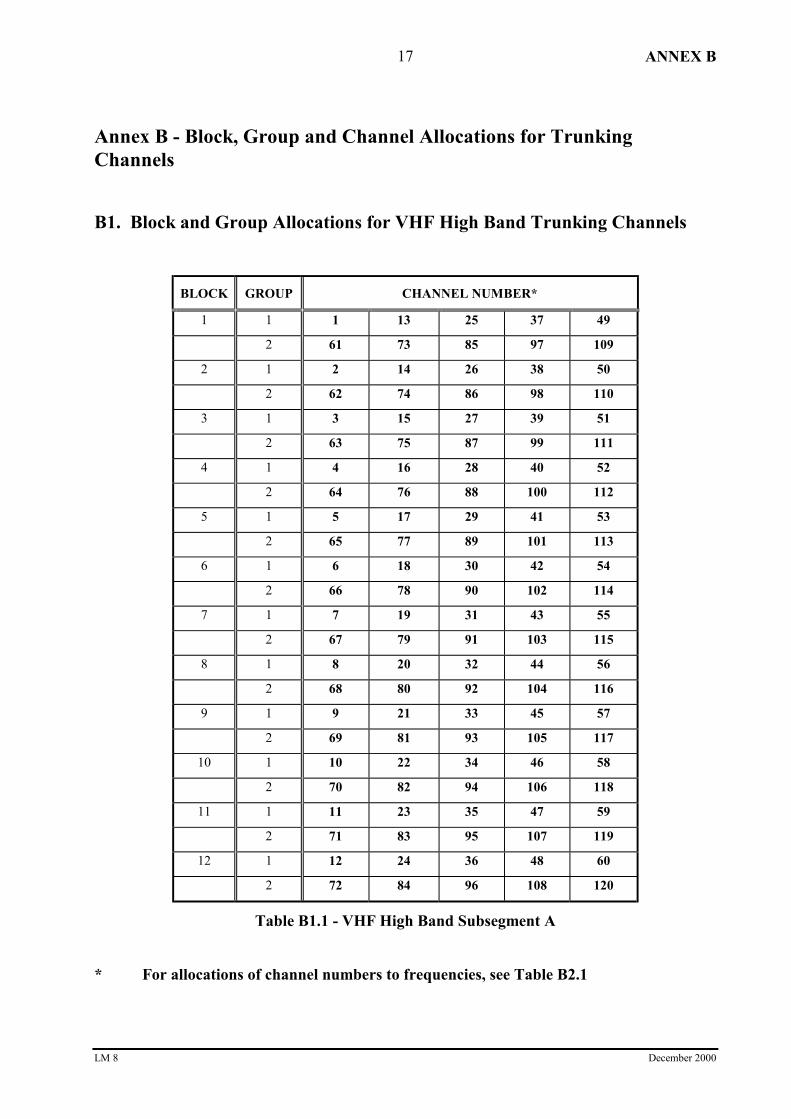
B1. Block and Group Allocations for VHF High Band Trunking Channels
BLOCK GROUP CHANNEL NUMBER*
1 1 1 13 25 37 49
2 61 73 85 97 109
2 1 2 14 26 38 50
2 62 74 86 98 110
3 1 3 15 27 39 51
2 63 75 87 99 111
4 1 4 16 28 40 52
2 64 76 88 100 112
5 1 5 17 29 41 53
2 65 77 89 101 113
6 1 6 18 30 42 54
2 66 78 90 102 114
7 1 7 19 31 43 55
2 67 79 91 103 115
8 1 8 20 32 44 56
2 68 80 92 104 116
9 1 9 21 33 45 57
2 69 81 93 105 117
10 1 10 22 34 46 58
2 70 82 94 106 118
11 1 11 23 35 47 59
2 71 83 95 107 119
12 1 12 24 36 48 60
2 72 84 96 108 120
Table B1.1 - VHF High Band Subsegment A
* For allocations of channel numbers to frequencies, see Table B2.1

ANNEX B
LM 8 December 2000
18
BLOCK GROUP CHANNEL NUMBER*
1 1 121 133 145 157 169
2 181 193 205 217 229
2 1 122 134 146 158 170
2 182 194 206 218 230
3 1 123 135 147 159 171
2 183 195 207 219 231
4 1 124 136 148 160 172
2 184 196 208 220 232
5 1 125 137 149 161 173
2 185 197 209 221 233
6 1 126 138 150 162 174
2 186 198 210 222 234
7 1 127 139 151 163 175
2 187 199 211 223 235
8 1 128 140 152 164 176
2 188 200 212 224 236
9 1 129 141 153 165 177
2 189 201 213 225 237
10 1 130 142 154 166 178
2 190 202 214 226 238
11 1 131 143 155 167 179
2 191 203 215 227 239
12 1 132 144 156 168 180
2 192 204 216 228 240
Table B1.2 - VHF High Band Subsegment B
* For allocations of channel numbers to frequencies, see Table B2.2

ANNEX B
LM 8 December 2000
19
B2. Channel Allocations for VHF High Band Trunking Channels
CHAN BASE TX BASE RX CHAN BASE TX BASE RX CHAN BASE TX BASE RX
1 165.20000 169.80000 41 165.70000 170.30000 81 166.20000 170.800002 165.21250 169.81250 42 165.71250 170.31250 82 166.21250 170.81250
3 165.22500 169.82500 43 165.72500 170.32500 83 166.22500 170.82500
4 165.23750 169.83750 44 165.73750 170.33750 84 166.23750 170.83750
5 165.25000 169.85000 45 165.75000 170.35000 85 166.25000 170.85000
6 165.26250 169.86250 46 165.76250 170.36250 86 166.26250 170.86250
7 165.27500 169.87500 47 165.77500 170.37500 87 166.27500 170.87500
8 165.28750 169.88750 48 165.78750 170.38750 88 166.28750 170.88750
9 165.30000 169.90000 49 165.80000 170.40000 89 166.30000 170.90000
10 165.31250 169.91250 50 165.81250 170.41250 90 166.31250 170.91250
11 165.32500 169.92500 51 165.82500 170.42500 91 166.32500 170.92500
12 165.33750 169.93750 52 165.83750 170.43750 92 166.33750 170.93750
13 165.35000 169.95000 53 165.85000 170.45000 93 166.35000 170.95000
14 165.36250 169.96250 54 165.86250 170.46250 94 166.36250 170.96250
15 165.37500 169.97500 55 165.87500 170.47500 95 166.37500 170.97500
16 165.38750 169.98750 56 165.88750 170.48750 96 166.38750 170.98750
17 165.40000 170.00000 57 165.90000 170.50000 97 166.40000 171.00000
18 165.41250 170.01250 58 165.91250 170.51250 98 166.41250 171.01250
19 165.42500 170.02500 59 165.92500 170.52500 99 166.42500 171.02500
20 165.43750 170.03750 60 165.93750 170.53750 100 166.43750 171.03750
21 165.45000 170.05000 61 165.95000 170.55000 101 166.45000 171.05000
22 165.46250 170.06250 62 165.96250 170.56250 102 166.46250 171.06250
23 165.47500 170.07500 63 165.97500 170.57500 103 166.47500 171.07500
24 165.48750 170.08750 64 165.98750 170.58750 104 166.48750 171.08750
25 165.50000 170.10000 65 166.00000 170.60000 105 166.50000 171.10000
26 165.51250 170.11250 66 166.01250 170.61250 106 166.51250 171.11250
27 165.52500 170.12500 67 166.02500 170.62500 107 166.52500 171.12500
28 165.53750 170.13750 68 166.03750 170.63750 108 166.53750 171.13750
29 165.55000 170.15000 69 166.05000 170.65000 109 166.55000 171.15000
30 165.56250 170.16250 70 166.06250 170.66250 110 166.56250 171.16250
31 165.57500 170.17500 71 166.07500 170.67500 111 166.57500 171.17500
32 165.58750 170.18750 72 166.08750 170.68750 112 166.58750 171.18750
33 165.60000 170.20000 73 166.10000 170.70000 113 166.60000 171.20000
34 165.61250 170.21250 74 166.11250 170.71250 114 166.61250 171.21250
35 165.62500 170.22500 75 166.12500 170.72500 115 166.62500 171.22500
36 165.63750 170.23750 76 166.13750 170.73750 116 166.63750 171.23750
37 165.65000 170.25000 77 166.15000 170.75000 117 166.65000 171.25000
38 165.66250 170.26250 78 166.16250 170.76250 118 166.66250 171.26250
39 165.67500 170.27500 79 166.17500 170.77500 119 166.67500 171.27500
40 165.68750 170.28750 80 166.18750 170.78750 120 166.68750 171.28750
Table B2.1 - VHF High Band Subsegment A

ANNEX B
LM 8 December 2000
20
CHAN BASE TX BASE RX CHAN BASE TX BASE RX CHAN BASE TX BASE RX
121 166.70000 171.30000 161 167.20000 171.80000 201 167.70000 172.30000122 166.71250 171.31250 162 167.21250 171.81250 202 167.71250 172.31250
123 166.72500 171.32500 163 167.22500 171.82500 203 167.72500 172.32500
124 166.73750 171.33750 164 167.23750 171.83750 204 167.73750 172.33750
125 166.75000 171.35000 165 167.25000 171.85000 205 167.75000 172.35000
126 166.76250 171.36250 166 167.26250 171.86250 206 167.76250 172.36250
127 166.77500 171.37500 167 167.27500 171.87500 207 167.77500 172.37500
128 166.78750 171.38750 168 167.28750 171.88750 208 167.78750 172.38750
129 166.80000 171.40000 169 167.30000 171.90000 209 167.80000 172.40000
130 166.81250 171.41250 170 167.31250 171.91250 210 167.81250 172.41250
131 166.82500 171.42500 171 167.32500 171.92500 211 167.82500 172.42500
132 166.83750 171.43750 172 167.33750 171.93750 212 167.83750 172.43750
133 166.85000 171.45000 173 167.35000 171.95000 213 167.85000 172.45000
134 166.86250 171.46250 174 167.36250 171.96250 214 167.86250 172.46250
135 166.87500 171.47500 175 167.37500 171.97500 215 167.87500 172.47500
136 166.88750 171.48750 176 167.38750 171.98750 216 167.88750 172.48750
137 166.90000 171.50000 177 167.40000 172.00000 217 167.90000 172.50000
138 166.91250 171.51250 178 167.41250 172.01250 218 167.91250 172.51250
139 166.92500 171.52500 179 167.42500 172.02500 219 167.92500 172.52500
140 166.93750 171.53750 180 167.43750 172.03750 220 167.93750 172.53750
141 166.95000 171.55000 181 167.45000 172.05000 221 167.95000 172.55000
142 166.96250 171.56250 182 167.46250 172.06250 222 167.96250 172.56250
143 166.97500 171.57500 183 167.47500 172.07500 223 167.97500 172.57500
144 166.98750 171.58750 184 167.48750 172.08750 224 167.98750 172.58750
145 167.00000 171.60000 185 167.50000 172.10000 225 168.00000 172.60000
146 167.01250 171.61250 186 167.51250 172.11250 226 168.01250 172.61250
147 167.02500 171.62500 187 167.52500 172.12500 227 168.02500 172.62500
148 167.03750 171.63750 188 167.53750 172.13750 228 168.03750 172.63750
149 167.05000 171.65000 189 167.55000 172.15000 229 168.05000 172.65000
150 167.06250 171.66250 190 167.56250 172.16250 230 168.06250 172.66250
151 167.07500 171.67500 191 167.57500 172.17500 231 168.07500 172.67500
152 167.08750 171.68750 192 167.58750 172.18750 232 168.08750 172.68750
153 167.10000 171.70000 193 167.60000 172.20000 233 168.10000 172.70000
154 167.11250 171.71250 194 167.61250 172.21250 234 168.11250 172.71250
155 167.12500 171.72500 195 167.62500 172.22500 235 168.12500 172.72500
156 167.13750 171.73750 196 167.63750 172.23750 236 168.13750 172.73750
157 167.15000 171.75000 197 167.65000 172.25000 237 168.15000 172.75000
158 167.16250 171.76250 198 167.66250 172.26250 238 168.16250 172.76250
159 167.17500 171.77500 199 167.67500 172.27500 239 168.17500 172.77500
160 167.18750 171.78750 200 167.68750 172.28750 240 168.18750 172.78750
Table B2.2 - VHF High Band Subsegment B
ANNEX B
LM 8 December 2000
21
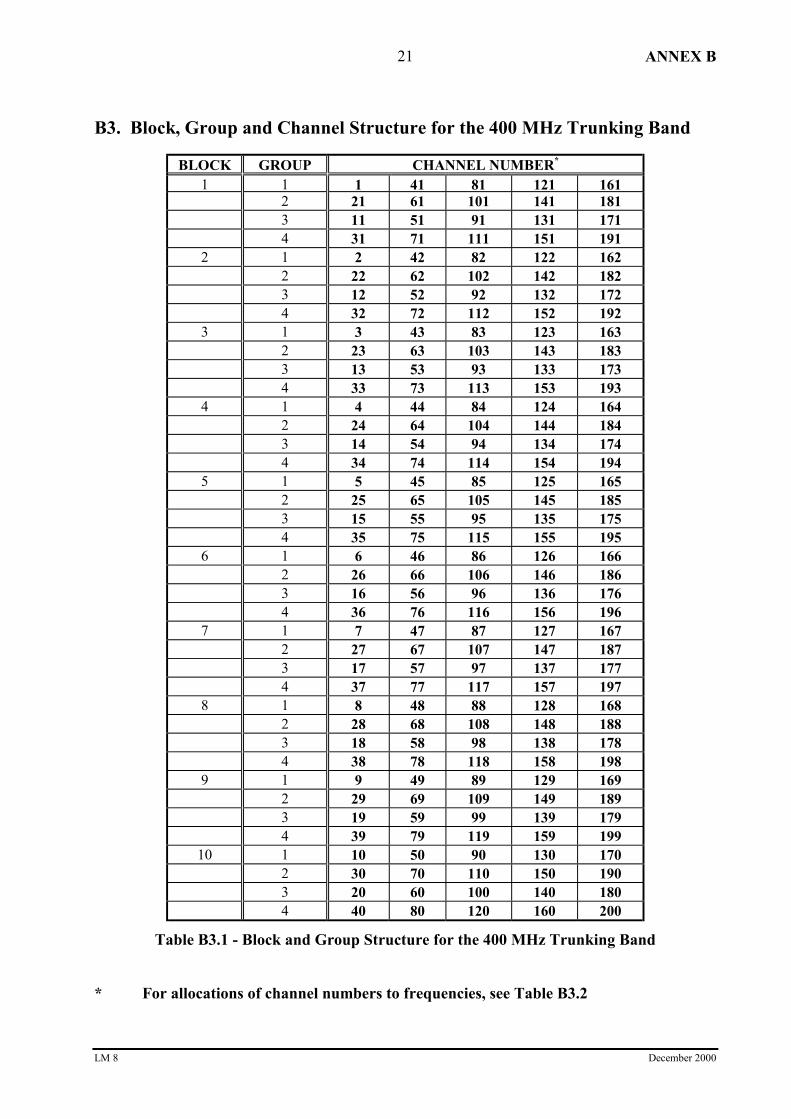
B3. Block, Group and Channel Structure for the 400 MHz Trunking Band
BLOCK GROUP CHANNEL NUMBER*
1 1 1 41 81 121 1612 21 61 101 141 1813 11 51 91 131 1714 31 71 111 151 191
2 1 2 42 82 122 1622 22 62 102 142 1823 12 52 92 132 1724 32 72 112 152 192
3 1 3 43 83 123 1632 23 63 103 143 1833 13 53 93 133 1734 33 73 113 153 193
4 1 4 44 84 124 1642 24 64 104 144 1843 14 54 94 134 1744 34 74 114 154 194
5 1 5 45 85 125 1652 25 65 105 145 1853 15 55 95 135 1754 35 75 115 155 195
6 1 6 46 86 126 1662 26 66 106 146 1863 16 56 96 136 1764 36 76 116 156 196
7 1 7 47 87 127 1672 27 67 107 147 1873 17 57 97 137 1774 37 77 117 157 197
8 1 8 48 88 128 1682 28 68 108 148 1883 18 58 98 138 1784 38 78 118 158 198
9 1 9 49 89 129 1692 29 69 109 149 1893 19 59 99 139 1794 39 79 119 159 199
10 1 10 50 90 130 1702 30 70 110 150 1903 20 60 100 140 1804 40 80 120 160 200
Table B3.1 - Block and Group Structure for the 400 MHz Trunking Band
* For allocations of channel numbers to frequencies, see Table B3.2

ANNEX B
LM 8 December 2000
22
CH#
BASETX
BASERX
CH#
BASETX
BASERX
CH#
BASETX
BASERX
CH#
BASETX
BASERX
1 415.5750 406.1250 51 416.2000 406.7500 101 416.8250 407.3750 151 417.4500 408.00002 415.5875 406.1375 52 416.2125 406.7625 102 416.8375 407.3875 152 417.4625 408.01253 415.6000 406.1500 53 416.2250 406.7750 103 416.8500 407.4000 153 417.4750 408.02504 415.6125 406.1625 54 416.2375 406.7875 104 416.8625 407.4125 154 417.4875 408.03755 415.6250 406.1750 55 416.2500 406.8000 105 416.8750 407.4250 155 417.5000 408.05006 415.6375 406.1875 56 416.2625 406.8125 106 416.8875 407.4375 156 417.5125 408.06257 415.6500 406.2000 57 416.2750 406.8250 107 416.9000 407.4500 157 417.5250 408.07508 415.6625 406.2125 58 416.2875 406.8375 108 416.9125 407.4625 158 417.5375 408.08759 415.6750 406.2250 59 416.3000 406.8500 109 416.9250 407.4750 159 417.5500 408.1000
10 415.6875 406.2375 60 416.3125 406.8625 110 416.9375 407.4875 160 417.5625 408.112511 415.7000 406.2500 61 416.3250 406.8750 111 416.9500 407.5000 161 417.5750 408.125012 415.7125 406.2625 62 416.3375 406.8875 112 416.9625 407.5125 162 417.5875 408.137513 415.7250 406.2750 63 416.3500 406.9000 113 416.9750 407.5250 163 417.6000 408.150014 415.7375 406.2875 64 416.3625 406.9125 114 416.9875 407.5375 164 417.6125 408.162515 415.7500 406.3000 65 416.3750 406.9250 115 417.0000 407.5500 165 417.6250 408.175016 415.7625 406.3125 66 416.3875 406.9375 116 417.0125 407.5625 166 417.6375 408.187517 415.7750 406.3250 67 416.4000 406.9500 117 417.0250 407.5750 167 417.6500 408.200018 415.7875 406.3375 68 416.4125 406.9625 118 417.0375 407.5875 168 417.6625 408.212519 415.8000 406.3500 69 416.4250 406.9750 119 417.0500 407.6000 169 417.6750 408.225020 415.8125 406.3625 70 416.4375 406.9875 120 417.0625 407.6125 170 417.6875 408.237521 415.8250 406.3750 71 416.4500 407.0000 121 417.0750 407.6250 171 417.7000 408.250022 415.8375 406.3875 72 416.4625 407.0125 122 417.0875 407.6375 172 417.7125 408.262523 415.8500 406.4000 73 416.4750 407.0250 123 417.1000 407.6500 173 417.7250 408.275024 415.8625 406.4125 74 416.4875 407.0375 124 417.1125 407.6625 174 417.7375 408.287525 415.8750 406.4250 75 416.5000 407.0500 125 417.1250 407.6750 175 417.7500 408.300026 415.8875 406.4375 76 416.5125 407.0625 126 417.1375 407.6875 176 417.7625 408.312527 415.9000 406.4500 77 416.5250 407.0750 127 417.1500 407.7000 177 417.7750 408.325028 415.9125 406.4625 78 416.5375 407.0875 128 417.1625 407.7125 178 417.7875 408.337529 415.9250 406.4750 79 416.5500 407.1000 129 417.1750 407.7250 179 417.8000 408.350030 415.9375 406.4875 80 416.5625 407.1125 130 417.1875 407.7375 180 417.8125 408.362531 415.9500 406.5000 81 416.5750 407.1250 131 417.2000 407.7500 181 417.8250 408.375032 415.9625 406.5125 82 416.5875 407.1375 132 417.2125 407.7625 182 417.8375 408.387533 415.9750 406.5250 83 416.6000 407.1500 133 417.2250 407.7750 183 417.8500 408.400034 415.9875 406.5375 84 416.6125 407.1625 134 417.2375 407.7875 184 417.8625 408.412535 416.0000 406.5500 85 416.6250 407.1750 135 417.2500 407.8000 185 417.8750 408.425036 416.0125 406.5625 86 416.6375 407.1875 136 417.2625 407.8125 186 417.8875 408.437537 416.0250 406.5750 87 416.6500 407.2000 137 417.2750 407.8250 187 417.9000 408.450038 416.0375 406.5875 88 416.6625 407.2125 138 417.2875 407.8375 188 417.9125 408.462539 416.0500 406.6000 89 416.6750 407.2250 139 417.3000 407.8500 189 417.9250 408.475040 416.0625 406.6125 90 416.6875 407.2375 140 417.3125 407.8625 190 417.9375 408.487541 416.0750 406.6250 91 416.7000 407.2500 141 417.3250 407.8750 191 417.9500 408.500042 416.0875 406.6375 92 416.7125 407.2625 142 417.3375 407.8875 192 417.9625 408.512543 416.1000 406.6500 93 416.7250 407.2750 143 417.3500 407.9000 193 417.9750 408.525044 416.1125 406.6625 94 416.7375 407.2875 144 417.3625 407.9125 194 417.9875 408.537545 416.1250 406.6750 95 416.7500 407.3000 145 417.3750 407.9250 195 418.0000 408.550046 416.1375 406.6875 96 416.7625 407.3125 146 417.3875 407.9375 196 418.0125 408.562547 416.1500 406.7000 97 416.7750 407.3250 147 417.4000 407.9500 197 418.0250 408.575048 416.1625 406.7125 98 416.7875 407.3375 148 417.4125 407.9625 198 418.0375 408.587549 416.1750 406.7250 99 416.8000 407.3500 149 417.4250 407.9750 199 418.0500 408.600050 416.1875 406.7375 100 416.8125 407.3625 150 417.4375 407.9875 200 418.0625 408.6125
Table B3.2 - Channel Allocations for the 400 MHz Trunking Band

ANNEX B
LM 8 December 2000
23
B4. Block, Group and Channel Structure for the 800 MHz Trunking Band
BLOCK GROUP CHANNEL NUMBER*
1 1 1 41 81 121 1612 21 61 101 141 1813 11 51 91 131 1714 31 71 111 151 191
2 1 2 42 82 122 1622 22 62 102 142 1823 12 52 92 132 1724 32 72 112 152 192
3 1 3 43 83 123 1632 23 63 103 143 1833 13 53 93 133 1734 33 73 113 153 193
4 1 4 44 84 124 1642 24 64 104 144 1843 14 54 94 134 1744 34 74 114 154 194
5 1 5 45 85 125 1652 25 65 105 145 1853 15 55 95 135 1754 35 75 115 155 195
6 1 6 46 86 126 1662 26 66 106 146 1863 16 56 96 136 1764 36 76 116 156 196
7 1 7 47 87 127 1672 27 67 107 147 1873 17 57 97 137 1774 37 77 117 157 197
8 1 8 48 88 128 1682 28 68 108 148 1883 18 58 98 138 1784 38 78 118 158 198
9 1 9 49 89 129 1692 29 69 109 149 1893 19 59 99 139 1794 39 79 119 159 199
10 1 10 50 90 130 1702 30 70 110 150 1903 20 60 100 140 1804 40 80 120 160 200
Table B4.1 - Block and Group Structure for the 800 MHz Trunking Band
* For allocations of channel numbers to frequencies, see Table B4.2

ANNEX B
LM 8 December 2000
24
CH#
BASETX
BASERX
CH#
BASETX
BASERX
CH#
BASETX
BASERX
CH#
BASETX
BASERX
1 865.0125 820.0125 51 866.2625 821.2625 101 867.5125 822.5125 151 868.7625 823.76252 865.0375 820.0375 52 866.2875 821.2875 102 867.5375 822.5375 152 868.7875 823.78753 865.0625 820.0625 53 866.3125 821.3125 103 867.5625 822.5625 153 868.8125 823.81254 865.0875 820.0875 54 866.3375 821.3375 104 867.5875 822.5875 154 868.8375 823.83755 865.1125 820.1125 55 866.3625 821.3625 105 867.6125 822.6125 155 868.8625 823.86256 865.1375 820.1375 56 866.3875 821.3875 106 867.6375 822.6375 156 868.8875 823.88757 865.1625 820.1625 57 866.4125 821.4125 107 867.6625 822.6625 157 868.9125 823.91258 865.1875 820.1875 58 866.4375 821.4375 108 867.6875 822.6875 158 868.9375 823.93759 865.2125 820.2125 59 866.4625 821.4625 109 867.7125 822.7125 159 868.9625 823.9625
10 865.2375 820.2375 60 866.4875 821.4875 110 867.7375 822.7375 160 868.9875 823.987511 865.2625 820.2625 61 866.5125 821.5125 111 867.7625 822.7625 161 869.0125 824.012512 865.2875 820.2875 62 866.5375 821.5375 112 867.7875 822.7875 162 869.0375 824.037513 865.3125 820.3125 63 866.5625 821.5625 113 867.8125 822.8125 163 869.0625 824.062514 865.3375 820.3375 64 866.5875 821.5875 114 867.8375 822.8375 164 869.0875 824.087515 865.3625 820.3625 65 866.6125 821.6125 115 867.8625 822.8625 165 869.1125 824.112516 865.3875 820.3875 66 866.6375 821.6375 116 867.8875 822.8875 166 869.1375 824.137517 865.4125 820.4125 67 866.6625 821.6625 117 867.9125 822.9125 167 869.1625 824.162518 865.4375 820.4375 68 866.6875 821.6875 118 867.9375 822.9375 168 869.1875 824.187519 865.4625 820.4625 69 866.7125 821.7125 119 867.9625 822.9625 169 869.2125 824.212520 865.4875 820.4875 70 866.7375 821.7375 120 867.9875 822.9875 170 869.2375 824.237521 865.5125 820.5125 71 866.7625 821.7625 121 868.0125 823.0125 171 869.2625 824.262522 865.5375 820.5375 72 866.7875 821.7875 122 868.0375 823.0375 172 869.2875 824.287523 865.5625 820.5625 73 866.8125 821.8125 123 868.0625 823.0625 173 869.3125 824.312524 865.5875 820.5875 74 866.8375 821.8375 124 868.0875 823.0875 174 869.3375 824.337525 865.6125 820.6125 75 866.8625 821.8625 125 868.1125 823.1125 175 869.3625 824.362526 865.6375 820.6375 76 866.8875 821.8875 126 868.1375 823.1375 176 869.3875 824.387527 865.6625 820.6625 77 866.9125 821.9125 127 868.1625 823.1625 177 869.4125 824.412528 865.6875 820.6875 78 866.9375 821.9375 128 868.1875 823.1875 178 869.4375 824.437529 865.7125 820.7125 79 866.9625 821.9625 129 868.2125 823.2125 179 869.4625 824.462530 865.7375 820.7375 80 866.9875 821.9875 130 868.2375 823.2375 180 869.4875 824.487531 865.7625 820.7625 81 867.0125 822.0125 131 868.2625 823.2625 181 869.5125 824.512532 865.7875 820.7875 82 867.0375 822.0375 132 868.2875 823.2875 182 869.5375 824.537533 865.8125 820.8125 83 867.0625 822.0625 133 868.3125 823.3125 183 869.5625 824.562534 865.8375 820.8375 84 867.0875 822.0875 134 868.3375 823.3375 184 869.5875 824.587535 865.8625 820.8625 85 867.1125 822.1125 135 868.3625 823.3625 185 869.6125 824.612536 865.8875 820.8875 86 867.1375 822.1375 136 868.3875 823.3875 186 869.6375 824.637537 865.9125 820.9125 87 867.1625 822.1625 137 868.4125 823.4125 187 869.6625 824.662538 865.9375 820.9375 88 867.1875 822.1875 138 868.4375 823.4375 188 869.6875 824.687539 865.9625 820.9625 89 867.2125 822.2125 139 868.4625 823.4625 189 869.7125 824.712540 865.9875 820.9875 90 867.2375 822.2375 140 868.4875 823.4875 190 869.7375 824.737541 866.0125 821.0125 91 867.2625 822.2625 141 868.5125 823.5125 191 869.7625 824.762542 866.0375 821.0375 92 867.2875 822.2875 142 868.5375 823.5375 192 869.7875 824.787543 866.0625 821.0625 93 867.3125 822.3125 143 868.5625 823.5625 193 869.8125 824.812544 866.0875 821.0875 94 867.3375 822.3375 144 868.5875 823.5875 194 869.8375 824.837545 866.1125 821.1125 95 867.3625 822.3625 145 868.6125 823.6125 195 869.8625 824.862546 866.1375 821.1375 96 867.3875 822.3875 146 868.6375 823.6375 196 869.8875 824.887547 866.1625 821.1625 97 867.4125 822.4125 147 868.6625 823.6625 197 869.9125 824.912548 866.1875 821.1875 98 867.4375 822.4375 148 868.6875 823.6875 198 869.9375 824.937549 866.2125 821.2125 99 867.4625 822.4625 149 868.7125 823.7125 199 869.9625 824.962550 866.2375 821.2375 100 867.4875 822.4875 150 868.7375 823.7375 200 869.9875 824.9875
Table B4.2 - Channel Allocations for the 800 MHz Trunking Band

ANNEX C
LM 8 December 2000
25
Annex C - Frequency-Distance Constraints
C1. Cull Limits Applicable to Frequency-Distance Constraints
Cull Frequency Range
Band ofOperation
Cull Radius Single FreqSegment
Two Freq Segment
Tx Rx
VHF MidBand
250 km ±±±±1.29 MHz ±±±±1.29 MHz ±±±±1.29 MHz
VHF HighBand
200 km ±±±±1.29 MHz ±±±±1.29 MHz ±±±±1.29 MHz
400 MHz
Band
200 km ±±±±1.2 MHz ±±±±1.2 MHz ±±±±1.2 MHz
800 MHzTrunking Band
200 km N/A ±±±±1.2 MHz ±±±±1.2 MHz
Table C1 - Cull Limits Applicable to Frequency-Distance Constraints

ANNEX C
LM 8 December 2000
26
C2. Frequency-Distance Constraints for Single Frequency LMRS in the VHFMid and High Bands
The following frequency-distance constraints apply whenever:
• an 83 W EIRP single-frequency system (proposed or existing) requires frequencycoordination;
• two-frequency systems are to be coordinated with one another, and one operates with reversefrequency sense to the other (ie, the transmit frequency of one is the same as the receivefrequency of the other); or
• a two-frequency system’s transmit frequency is close to a single frequency service receivefrequency.
Frequency Distance Constraints for Single Frequency Services
Frequency Offset (kHz) Distance Separation (km)
Proposed 12.5 kHz
from Existing
Existing
25 kHz
Existing
12.5 kHz
<1.25 140 140
<3.75 140 140
<6.25 140 120
<8.75 120 80
<11.25 100 35
<13.75 80 5
<16.25 60 5
<18.75 35 5
<21.25 8 5
<23.75 5 5
<26.25 5 5
<45 5 5
<75 5 5
<105 3 3
<135 2.5 2.5
<165 2 2
<195 1.4 1.4
<225 .9 .9
<255 .6 .6
<285 .4 .4
<315 .3 .3
<1290 .2 .2
Table C2 - Frequency-Distance Constraints for 12.5 kHz Single FrequencyLMRS in the VHF Mid and High Bands

ANNEX C
LM 8 December 2000
27
C3. Frequency-Distance Constraints for Single Frequency LMRS in the400 MHz Band
The following frequency-distance constraints apply whenever:
• an 83 W EIRP single-frequency system (proposed or existing) requires frequencycoordination;
• two-frequency systems are to be coordinated with one another, and one operates with reversefrequency sense to the other (ie, the transmit frequency of one is the same as the receivefrequency of the other); or
• a two-frequency system’s transmit frequency is close to a single frequency service receivefrequency.
Frequency Offset (kHz) Distance Separation (km)
Proposed 12.5 kHz Txfrom Existing Rx
Existing12.5 kHz Rx
Existing25 kHz Rx
< 3 120 120<= 12.5 90 105<= 25 4 15
<= 37.5 2 2<= 50 0.7 0.7
<= 62.5 0.6 0.6<= 75 0.5 0.5
<= 87.5 0.4 0.4<= 100 0.4 0.4<= 200 0.2 0.2
Table C3.1 - Frequency-Distance Constraints for 12.5 kHz SingleFrequency LMRS in the 400 MHz Band
Frequency Offset (kHz) Distance Separation (km)
Proposed 25 kHz Txfrom Existing Rx
Existing12.5 kHz Rx
Existing25 kHz Rx
< 3 120 120<= 12.5 95 105<= 25 17 40
<= 37.5 3 3.5<= 50 1.5 1.5
<= 62.5 1 1<= 75 0.6 0.6
<= 87.5 0.55 0.55<= 100 0.5 0.5<= 200 0.2 0.2
Table C3.2 - Frequency-Distance Constraints for 25 kHz SingleFrequency LMRS in the 400 MHz Band

ANNEX C
LM 8 December 2000
28
C4. Frequency-Distance Constraints for Single Frequency LPMRS in the400 MHz Band
The following frequency-distance constraints apply whenever:
• an 8.3 W EIRP single-frequency LPMRS (proposed or existing) requires frequencycoordination;
• two-frequency LPMRS are to be coordinated with one another, and one operates with reversefrequency sense to the other (ie, the transmit frequency of one is the same as the receivefrequency of the other); or
• a two-frequency LPMRS transmit frequency is close to a single frequency service receivefrequency.
Frequency Offset (kHz) Distance Separation (km)
Proposed 12.5 kHz Txfrom Existing Rx
Existing12.5 kHz Rx
Existing25 kHz Rx
< 3 10 10<= 12.5 3 6<= 25 0.4 0.4
<= 37.5 0.2 0.2
Table C4.1 - Frequency-Distance Constraints for 12.5 kHz SingleFrequency LPMRS in the 400 MHz Band
Frequency Offset (kHz) Distance Separation (km)
Proposed 25 kHz Txfrom Existing Rx
Existing12.5 kHz Rx
Existing25 kHz Rx
< 3 10 10<= 12.5 5 7<= 25 0.5 0.8
<= 37.5 0.2 0.2Table C4.2 - Frequency-Distance Constraints for 25 kHz Single
Frequency LPMRS in the 400 MHz Band

ANNEX C
LM 8 December 2000
29
C5. Frequency-Distance Constraints for Two Frequency LMRS in the VHFMid and High Bands
Frequency Distance Constraints for Two Frequency Services
Frequency Offset (kHz) Distance Separation (km)
Proposed 12.5 kHz
from Existing
Existing
25 kHz
Existing
12.5 kHz
<1.25 100 100
<3.75 100 100
<6.25 100 80
<8.75 100 40
<11.25 80 10
<13.75 60 0
<16.25 40 0
<18.75 20 0
<21.25 10 0
<23.75 5 0
<199.0 0.2 0
Table C5 - Frequency-Distance Constraints for Two Frequency LMRSin the VHF Mid and High Bands

ANNEX C
LM 8 December 2000
30
C6. Frequency-Distance Constraints for Two Frequency LMRS in the400 MHz Band
The following frequency-distance constraints apply whenever both systems to be coordinated(proposed and existing) use two frequency operation, and have the same frequency sense.
Frequency Offset (kHz) Distance Separation (km)
Proposed 12.5 kHz
LMRS from Existing
Existing
25 kHz
Existing
12.5 kHz
< 12.5 100 100
< 25 80 0
>= 25 0 0
Proposed 25 kHz
LMRS from Existing
< 12.5 100 100
< 25 100 55
>= 25 0 0
Table C6 - Frequency-Distance Constraints for Two Frequency LMRS inthe 400 MHz Band
ANNEX C
LM 8 December 2000
31
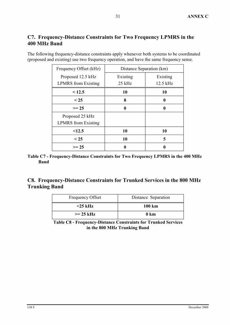
C7. Frequency-Distance Constraints for Two Frequency LPMRS in the400 MHz Band
The following frequency-distance constraints apply whenever both systems to be coordinated(proposed and existing) use two frequency operation, and have the same frequency sense.
Frequency Offset (kHz) Distance Separation (km)
Proposed 12.5 kHz
LPMRS from Existing
Existing
25 kHz
Existing
12.5 kHz
< 12.5 10 10
< 25 8 0
>= 25 0 0
Proposed 25 kHz
LPMRS from Existing
<12.5 10 10
< 25 10 5
>= 25 0 0
Table C7 - Frequency-Distance Constraints for Two Frequency LPMRS in the 400 MHzBand
C8. Frequency-Distance Constraints for Trunked Services in the 800 MHzTrunking Band
Frequency Offset Distance Separation
<25 kHz 100 km
>= 25 kHz 0 km
Table C8 - Frequency-Distance Constraints for Trunked Servicesin the 800 MHz Trunking Band

ANNEX D
LM 8 December 2000
32
Annex D - Intermodulation Checks
D1. Cull Limits Applicable to Intermodulation Checks
Intermodulation Type Third OrderIntermodulation
Fifth Order Intermodulation
Receiver Intermodulation
Caused in ProposedReceiver
Tx within2 km & 2.25 MHz
Tx within0.2 km & 0.375 MHz
Caused by ProposedTransmitter as Outer
Tx within4 km & 1.125 MHz
Rx within2 km & 2.25 MHz
Tx within0.4 km & 0.125 MHz
Rx within0.2 km & 0.375 MHz
Caused by ProposedTransmitter as Inner
Tx within4 km & 1.125 MHz
Rx within2 km & 1.125 MHz
Tx within0.4 km & 0.125 MHz
Rx within0.2 km & 0.25 MHz
Transmitter Intermodulation
Third Order & FifthOrder Intermodulation
Tx within 0.2 km & within the band 20 MHzabove and 20 MHz below the proposedfrequency
Table D1 - Cull Limits Applicable to Intermodulation Checks

ANNEX D
LM 8 December 2000
33
D2. Frequency Offset from Victim Receiver Within Which anIntermodulation ‘Hit’ is Deemed to Occur
Frequency offset from receiver centre frequency (±±±± kHz)
Interfererchannel width*
Receiver channel width / Intermodulation Order
12.5 kHz 25 kHz
3rd order 5th order 3rd order 5th order
12.5 kHz 15 17.5 19.5 22
25 kHz 21.5 26.5 26 31
Table D2 - Frequency Offset from Victim Receiver Within which anIntermodulation ‘Hit’ is Deemed to Occur
* The interferer channel width is taken as the wider of the two intermodulation-producing interferers
D3. Expressions for Evaluating Intermodulation Interference
The following equations should be used to evaluate receiver generated intermoduationinterference. When the equations are satisfied, the level of the intermodulation product is nothigh enough1 to cause harmful interference.
The equation for two signal 3rd order receiver intermodulation is:
PR + 2*(EIRP - Lb inner + Lc - RFinner) + (EIRP - Lb outer + Lc - RFouter) + ECR 2/3 < RS...........(1)
The equation for two signal 5th order receiver intermodulation is:
PR + 3*(EIRP - Lb inner + Lc - RFinner) + 2*(EIRP - Lb outer + Lc - RFouter) + ECR 2/5 < RS.......(2)
The equation for three signal 3rd order receiver intermodulation is:
PR + (EIRP - Lb inner + Lc - RFinner) + (EIRP - Lb middle + Lc - RFmiddle) +(EIRP - Lb outer + Lc - RFouter) + ECR 3/3 < RS.......................................................................(3)
The parameter values applicable to equations (1), (2) and (3) above are specified in Table D3.
1 It is assumed that harmful interference will occur if the level of the intermodulation product is greater than the usable sensitivity level (RS).

ANNEX D
LM 8 December 2000
34
D4. Parameter Values Applicable to Intermodulation Checks
Parameter Assumed Value
RS (Base Receiver Usable Sensitivity2) -119 dBm (800 MHz Trunking Band)
-116 dBm (400 MHz Band)
-107 dBm (VHF High Band)
-101 dBm (VHF Mid Band)
PR (Protection Ratio) 5 dB for 12 dB SINAD
EIRP (Transmitter EIRP) 83 W (for LMRS)
8.3 W (for LPMRS)
Lb (propagation loss: from ‘inner’ or‘outer’ transmitter to victim receiver)
Free Space Loss + 10 dB
Lc (antenna gain and feeder loss) 2 dBi (VHF)
6 dBi (400 MHz & 800 MHz Bands)
RF (receiver front-end response:achieved by the RF selectivity of areceiver in conjunction with a cavityfilter)
For the VHF Mid and High Bands:
2 dB for Freq Offset <= 0.06 MHz
23.3 + 18.7*log(Freq Offset) dB for 0.06 < Freq Offset <= 1.5 MHz
23.3 + 18.7*log(Freq Offset) + (Freq Offset – 1.5)*18/1.5 dBfor 1.5 MHz < Freq Offset <= 4.4 MHz
70 dB for Freq Offset > 4.4 MHz
For the 400 MHz Band:
5 dB for Freq Offset <=0.1 MHz
5 + 60 log [1+ (2 ×××× (Freq Offset - 0.1)/1.5)0.8 ]dBfor 0.1 < Freq Offset <= 15 MHz
70 dB for Freq Offset > 15 MHz
For the 800 MHz Trunking Band:
2 + 60*log[1 + (2*Freq Offset/5)1.5] dBfor Freq Offset <= 2.5 MHz
2 + 60*log[1 + (2*Freq Offset/5)2] dBfor 2.5 < Freq Offset <= 9 MHz
70 dB for Freq Offset > 9 MHz
ECR (effective conversion ratio ofintermodulation products)
3 Signal Third Order: ECR 3/3 = -5 dB
2 Signal Third Order: ECR 2/3 = -9 dB
2 Signal Fifth Order: ECR 2/5 = -28 dB
Table D3 - Parameter Values Applicable to Intermodulation Checks
2 These are static usable sensitivity levels assumed by the service model for base receivers in built up areas and take into consideration manmade noise levels. It is expected that receivers will have bench measured sensitivity levels at their rf input terminals better than thosespecified.
ANNEX E
LM 8 December 2000
35
Annex E - Inter-service Coordination
The following inter-service coordination requirements have been prepared by the ACA. Notethat this list is not exhaustive. In some cases, specific ITU-R Recommendations may exist toaddress inter-service coordination. However, because of the diversity and complexity of sharingsituations which may arise, it is not possible to provide rigorous and explicit procedures coveringall inter-service coordination requirements. In these cases, coordination defaults to theidentification of all non-homogeneous services in the band in question, followed by a manualassessment of their impact on the interference environment.
E1. VHF Mid and High Assignments Adjacent to TelevisionChannels 2, 3 and 6
The frequency-distance constraints detailed in RALI LM 5 [2] should be observed for all VHFMid and High band land mobile frequency assignments within 7 MHz below or 2 MHz above theedges of VHF television channels 2, 3 or 6.
E2. 400 MHz Assignments in the Vicinity of Wideband Fixed Services
The frequency coordination requirements detailed in RALI FX 5 [6] should be observed for403 – 500 MHz assignments within 160 km of wideband fixed services.
There are restrictions on the assignment of certain trunked channels in low demand areas toprovide protection to wideband fixed services. These restrictions are detailed in Embargo 19 ofRALI MS 3 [4].
E3. 400 MHz Assignments Within 675 km of Jervis Bay
The frequency coordination requirements detailed in Embargo 11 of RALI MS 3 [4] must beobserved for single frequency land-mobile assignments within the 410.96875 - 412.25 MHz partof Segment H within 675 km of of Jervis Bay, NSW.
E4. 800 MHz Trunking Assignments Adjacent to UHF Television Channel 69
The frequency coordination requirements detailed in RALI LM 3 [1] should be observed for800 MHz trunking assignments on channels 1, 2, 3 or 4 within 200 km of a UHF televisionchannel 69 transmitter.
E5. 800 MHz Trunking Assignments Adjacent to Spectrum Licensed Services
Immediately adjacent to the 800 MHz trunking segments are the segments used by the AMPSmobile telephone service (825 - 845/870 - 890 MHz) which are being progressively withdrawnand are intended to be spectrum licensed.
Spectrum licensed receiver compatibility requirements are specified in RadiocommunicationsAdvisory Guidelines (Managing Interference from Apparatus-licensed Transmitters - 800 MHzBand) 1998 and should be observed for new 800 MHz trunking assignments to protect registeredspectrum licensed receivers from harmful interference. Note that registered spectrum licensedreceivers will appear in the ACA’s Register of Radiocommunication Licences.


![[2020] No. ELECTRONIC COMMUNICATIONS · individual frequency lot assignment stage bid and 700 MHz paired frequency lot assignment stage bid; “valid assignment stage form” shall](https://static.fdocuments.net/doc/165x107/5e526ab42242284fbc20949f/2020-no-electronic-communications-individual-frequency-lot-assignment-stage-bid.jpg)