FreeSpace DXA 2120 Digital Mixer/Amplifier Owner’s … the power cord from being walked on or ......
34
FreeSpace ® DXA 2120 Digital Mixer/Amplifier Owner’s Guide
Transcript of FreeSpace DXA 2120 Digital Mixer/Amplifier Owner’s … the power cord from being walked on or ......

FreeSpace® DXA 2120 Digital Mixer/Amplifier
Owner’s Guide
Cover_ENG_GER.fm Page 1 Monday, February 12, 2007 10:16 AM

Safety Information
Safety Information ENG.fm Page 2 Friday, February 9, 2007 2:08 PM
Please read this owner’s guidePlease take the time to follow the instructions in this owner’s guide carefully. It will help you set up and operate your system properly and enjoy all of its advanced features. Please save this owner’s guide for future reference.
WARNING: To reduce the risk of fire or electrical shock, do not expose the product to rain or moisture.
WARNING: The apparatus shall not be exposed to dripping or splashing, and objects filled with liquids, such as vases, shall not be placed on the apparatus. As with any electronic products, use care not to spill liquids into any part of the system. Liquids can cause a failure and/or a fire hazard.
The lightning flash with arrowhead symbol within an equilateral triangle alerts the user to the presence of uninsulated, dangerous voltage within the system enclosure that may be of sufficient magnitude to constitute a risk of electrical shock.
The exclamation point within an equilateral triangle, as marked on the system, is intended to alert the user to the presence of important operating and maintenance instructions in this owner’s guide.
WARNING: No naked flame sources, such as lighted candles, should be placed on the apparatus.
CAUTION: Make no modification to the system or accessories. Unauthorized alterations may compromise safety, regulatory compliance, and system performance.
CAUTION: This product shall be connected to a mains socket outlet with a protective earthing connection.
This product conforms to the EMC Directive 89/336/EEC and to the Low Voltage Directive 73/23/EEC. The complete Declaration of Conformity can be found on www.Bose.com/static/compliance/index.html.
Note: Where the mains plug or appliance coupler is used as the disconnect device, such disconnect device shall remain readily operable.
Note: The product must be used indoors. It is neither designed nor tested for use outdoors, in recreation vehicles, or on boats.
Note: Provide an earth connection before the main plug is connected to the mains.
Safety Information
Safety Information ENG.fm Page 3 Friday, February 9, 2007 2:08 PM
Important safety instructions1. Read these instructions. 2. Keep these instructions – for future reference.3. Heed all warnings – on the product and in the owner’s guide.4. Follow all instructions. 5. Do not use this apparatus near water or moisture.6. Clean only with a dry cloth. 7. Do not block any ventilation openings. Install in accordance
with the manufacturer’s instructions – To ensure reliable opera-tion of the product and to protect it from overheating, put the prod-uct in a position and location that will not interfere with its proper ventilation.
8. Do not install near any heat sources, such as radiators, heat registers, stoves, or other apparatus (including amplifiers) that produce heat.
9. Do not defeat the safety purpose of the polarized or grounding-type plug. A polarized plug has two blades with one wider than the other. A grounding-type plug has two blades and a third grounding prong. The wider blade or third prong are provided for your safety. If the provided plug does not fit in your outlet, consult an electrician for replacement of the obsolete outlet.
10. Protect the power cord from being walked on or pinched, par-ticularly at plugs, convenience receptacles, and the point where they exit from the apparatus.
11. Only use attachments/accessories specified by the manufacturer.
12. Use only with the cart, stand, tripod, bracket, or table specified by the manufacturer or sold with the apparatus. When a cart is used, use caution when moving the cart/apparatus combination to avoid injury from tip-over.
13. Unplug this apparatus during lightning storms or when unused for long periods of time – to prevent damage to this product.
14. Refer all servicing to qualified service personnel. Servicing is required when the apparatus has been damaged in any way such as power-supply cord or plug is damaged; liquid has been spilled or objects have fallen into the apparatus; the apparatus has been exposed to rain or moisture, does not operate nor-mally, or has been dropped – Do not attempt to service this prod-uct yourself. Opening or removing covers may expose you to dangerous voltages or other hazards. Please call Bose to be referred to an authorized service center near you.
15. To prevent risk of fire or electric shock, avoid overloading wall outlets, extension cords, or integral convenience receptacles.
16. Do not let objects or liquids enter the product – as they may touch dangerous voltage points or short-out parts that could result in a fire or electric shock.
17. See product enclosure for safety related markings. 18. No naked flame sources, such as lighted candles, should be
placed on the apparatus.
Information about products that generate electrical noiseIf applicable, this equipment has been tested and found to com-ply with the limits for a Class A digital device, pursuant to Part 15 of the FCC rules. These limits are designed to provide reasonable protection against harmful interference in a residential installa-tion. This equipment generates, uses, and can radiate radio fre-quency energy and, if not installed and used in accordance with the instructions, may cause harmful interference to radio commu-nications. However, this is no guarantee that interference will not occur in a particular installation. If this equipment does cause harmful interference to radio or television reception, which can be determined by turning the equipment off and on, you are encour-aged to try to correct the interference by one or more of the fol-lowing measures:
• Reorient or relocate the receiving antenna.
• Increase the separation between the equipment and receiver.
• Connect the equipment to an outlet on a different circuit than the one to which the receiver is connected.
• Consult the dealer or an experienced radio/TV technician for help.
Note: Unauthorized modification of this product could void the user’s authority to operate this equipment.
This product complies with the Canadian ICES-003 Class A specifications.
The information furnished in this user’s guide does not include all of the details of design, production, or variations of the equip-ment. Nor does it cover every possible situation which may arise during installation, operation, or maintenance.
4 of 36
Contents
1.0 Introduction .............................................. 5
1.1 The Bose® FreeSpace® DXA 2120 Digital Mixer/Amplifier ...........................................5
1.2 Supplied with the product ....................................5
1.3 Mixer/Amplifier accessories .................................5
2.0 Hardware Description .............................. 6
2.1 Front panel with open compartment ....................62.1.1 System Controls ..........................................62.1.2 Control Compartment ..................................62.1.3 Input Controls ..............................................6
2.2 Front panel with compartment closed ..................6
2.3 Rear panel ............................................................72.3.1 Audio source inputs .....................................72.3.2 Outputs ........................................................72.3.3 Control input ................................................72.3.4 Power ...........................................................72.3.5 Communication ...........................................7
3.0 Operation Mode Options ......................... 8
3.1 Operation mode options .......................................83.1.1 Mixer Mode ..................................................83.1.2 Stereo Select Mode .....................................93.1.3 Dual Mono Select Mode ..............................9
4.0 Hardware Installation ............................. 10
4.1 Introduction ........................................................10
4.2 Included accessories ..........................................10
4.3 Placement guidelines .........................................10
4.4 Shelf mounting the chassis ................................10
4.5 Rack mounting the chassis ................................10
4.6 User interface (accessory) ..................................114.6.1 User interface installation ..........................11
4.6.1.1 Additional equipment required (not supplied) ...............................114.6.1.2 Assembly .......................................114.6.1.3 Recommended cable lengths ........114.6.1.4 User interface connections ............114.6.1.5 User interface wiring ......................124.6.1.6 Detailed schematics of user interfaces ...........................................12
4.7 System wiring ..................................................... 124.7.1 LINE 1-4 source inputs .............................. 12
4.7.1.1 RCA connections .......................... 124.7.1.2 Euroblock connections .................. 13
4.7.2 DIRECT source input ................................. 134.7.3 PAGE source input .................................... 144.7.4 OUTPUT connections ............................... 144.7.5 AUX output connection ............................. 15
4.8 AC POWER connection ..................................... 154.8.1 Input voltage setting (120 or 220-240V) .... 154.8.2 Fuse type ................................................... 154.8.3 AC POWER connection ............................. 15
4.9 DC POWER connection ..................................... 15
5.0 System Setup ..........................................16
5.1 System setup introduction ................................. 16
5.2 System setup procedure .................................... 165.2.1 Selecting an operation mode .................... 165.2.2 Setting the options for that mode ............. 16
5.3 Mixer Mode settings .......................................... 17
5.4 Stereo Select Mode settings .............................. 22
5.5 Dual Mono Select Mode settings ....................... 26
5.6 Overview of Utility Mode settings ...................... 30
6.0 User Interfaces ........................................31
6.1 User interface use .............................................. 316.1.1 Mode user interface requirements ............ 31
6.1.1.1 Mixer Mode user interface application ................................................. 316.1.1.2 Stereo Select Mode user interface application .......................... 316.1.1.3 Dual Mono Select Mode user interface application .......................... 31
7.0 Troubleshooting Table ...........................32
7.1 Technical assistance .......................................... 32
8.0 Reference ................................................33
8.1 Factory Default Settings ..................................... 33
FS_Mixer_AmplifierTOC.fm Page 4 Monday, February 12, 2007 8:49 AM
5 of 36
1.0 Introduction
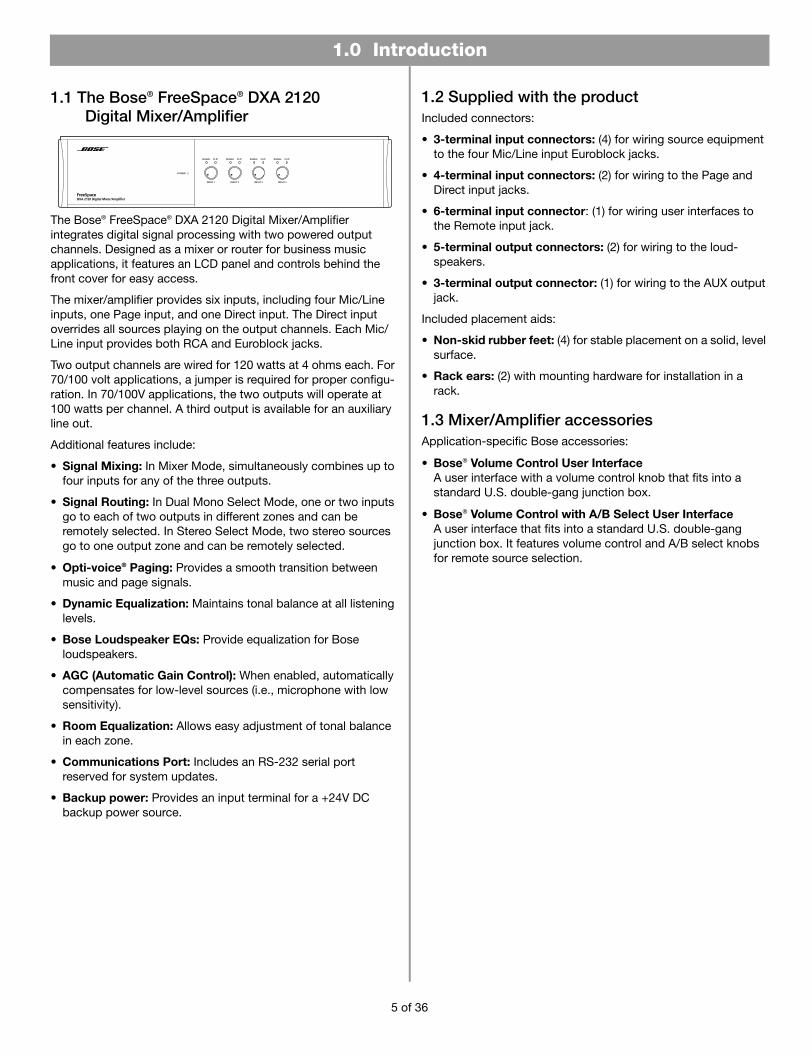
1.1 The Bose® FreeSpace® DXA 2120 Digital Mixer/Amplifier
The Bose® FreeSpace® DXA 2120 Digital Mixer/Amplifier integrates digital signal processing with two powered output channels. Designed as a mixer or router for business music applications, it features an LCD panel and controls behind the front cover for easy access.
The mixer/amplifier provides six inputs, including four Mic/Line inputs, one Page input, and one Direct input. The Direct input overrides all sources playing on the output channels. Each Mic/Line input provides both RCA and Euroblock jacks.
Two output channels are wired for 120 watts at 4 ohms each. For 70/100 volt applications, a jumper is required for proper configu-ration. In 70/100V applications, the two outputs will operate at 100 watts per channel. A third output is available for an auxiliary line out.
Additional features include:
• Signal Mixing: In Mixer Mode, simultaneously combines up to four inputs for any of the three outputs.
• Signal Routing: In Dual Mono Select Mode, one or two inputs go to each of two outputs in different zones and can be remotely selected. In Stereo Select Mode, two stereo sources go to one output zone and can be remotely selected.
• Opti-voice® Paging: Provides a smooth transition between music and page signals.
• Dynamic Equalization: Maintains tonal balance at all listening levels.
• Bose Loudspeaker EQs: Provide equalization for Bose loudspeakers.
• AGC (Automatic Gain Control): When enabled, automatically compensates for low-level sources (i.e., microphone with low sensitivity).
• Room Equalization: Allows easy adjustment of tonal balance in each zone.
• Communications Port: Includes an RS-232 serial port reserved for system updates.
• Backup power: Provides an input terminal for a +24V DC backup power source.
1.2 Supplied with the productIncluded connectors:
• 3-terminal input connectors: (4) for wiring source equipment to the four Mic/Line input Euroblock jacks.
• 4-terminal input connectors: (2) for wiring to the Page and Direct input jacks.
• 6-terminal input connector: (1) for wiring user interfaces to the Remote input jack.
• 5-terminal output connectors: (2) for wiring to the loud- speakers.
• 3-terminal output connector: (1) for wiring to the AUX output jack.
Included placement aids:
• Non-skid rubber feet: (4) for stable placement on a solid, level surface.
• Rack ears: (2) with mounting hardware for installation in a rack.
1.3 Mixer/Amplifier accessoriesApplication-specific Bose accessories:
• Bose® Volume Control User Interface A user interface with a volume control knob that fits into a standard U.S. double-gang junction box.
• Bose® Volume Control with A/B Select User Interface A user interface that fits into a standard U.S. double-gang junction box. It features volume control and A/B select knobs for remote source selection.
1.0 Introduction.fm Page 5 Monday, February 12, 2007 8:50 AM

2.0 Hardware Description.fm Page 6 Monday, February 12, 2007 8:51 AM
2.0 Hardware Description
2.1 Front panel with open compartment
1 2 3 4
6
8
9 10
7
5
2.1.1 System Controls1 LCD panel – Displays menu selections for configuring and
viewing system settings.
2 Directional buttons – Navigates system menus and setting options shown on the LCD.
3 SELECT button – Confirms selections and settings in the system menus.
4 POWER LED – Blue light indicates the system is on. No light when unit is off.
5 SIGNAL and CLIP LEDs – Shows signal states for OUTPUT 1, OUTPUT 2, PAGE, and DIRECT.
Signal Unlit = No signal Clip Unlit = No clipping
Signal Green = Signal present Clip Red = Clipping
6 GAIN knobs – Adjusts gain for OUTPUT 1, OUTPUT 2, and PAGE.
7 BASS and TREBLE knobs – Adjusts tonal balance for OUTPUT 1 and OUTPUT 2.
2.1.2 Control Compartment8 Enclosure door – Conceals system controls.
2.1.3 Input Controls9 SIGNAL and CLIP LEDs – Shows signal states for
Inputs 1-4.
Signal Unlit = No signal Clip Unlit = No clipping
Signal Green = Signal present Clip Red = Clipping
10 Gain knobs – Adjusts gain for INPUT 1- INPUT 4.
2.2 Front panel with compartment closed
21
1 Door – Provides access to system controls. 2 Power status window – Reveals Power LED.
6 of 36

2.0 Hardware Description
2.0 Hardware Description.fm Page 7 Monday, February 12, 2007 8:51 AM
2.3 Rear panel
1 3 2 4 5 8 7 9 10
121314
116
2.3.1 Audio source inputs1 LINE INPUTS – Two unbalanced RCA audio jacks per input
(summed to mono).
2 MIC/LINE INPUTS – Balanced Euroblock input jacks. One per input.
3 MIC/LINE switch – Adjusts for the proper signal level being used with the four Euroblock input connectors. (Mic connections require using the Euroblock input jacks.)
4 DIRECT INPUT – Balanced override input jack.
5 PAGE INPUT – Balanced audio input jack.
2.3.2 Outputs6 AUX OUTPUT – Line-level signal output for other amplified
equipment.
7 OUTPUTS 1 and 2 – Speaker connections for two powered outputs (70V, 100V, or 4 ohms operation).
2.3.3 Control input8 REMOTE – Input jack for volume-only control and volume
control with A/B select user interfaces.
2.3.4 Power9 BACKUP POWER – For connection to backup power
source.
10 POWER OFF/ON – AC power switch.
11 FUSE – 120V T6.3AL/250V or 220-240V T3.15AL/250V.
12 AC mains line cord jack – AC line voltage input.
13 120V/220-240V switch – Switches between 120V and 220-240V AC input voltage. This switch is not provided on 100V AC input voltage models.
2.3.5 Communication14 COM – RS-232 serial port is reserved for system updates.
7 of 36

3.0 Planning the Install.fm Page 8 Monday, February 12, 2007 8:51 AM
3.0 Operation Mode Options
3.1 Operation mode optionsBefore making connections, decide how you want the sound sources distributed throughout the site. This depends on whether the area is specified for one or two zones, the kind of coverage needed, and the sources to be used.
The mixer/amplifier provides three different modes of operation.
• Mixer Mode
In Mixer Mode, the system can mix up to four mic/line inputs to each of the two output channels for use in one or two zones.
• Stereo Select Mode
In Stereo Select Mode, with up to two stereo sources connected and using both output channels, the system provides stereo sound to a single output zone. Refer to “Stereo Select Mode” on page 9.
• Dual Mono Select Mode
In Dual Mono Select Mode, with up to two input sources connected to each of the two output channels, the system provides audio in two zones. Refer to “Dual Mono Select Mode” on page 9.
3.1.1 Mixer ModeLine-level sources can be connected using the RCA jacks or Euroblock connectors. The system sums the two RCA jacks for each input to mono.
Microphones must be connected using the Euroblock connec-tors. Make sure the MIC/LINE switch is set to MIC.
Mixer mode sources can be routed to either or both outputs, as shown below.
Sources can be independently routed to the auxiliary output.
In normal operation, the OUTPUT 1 and 2 gain controls are used to control the gains of OUTPUT 1 and 2, respectively. In this mode, you have the MASTERVOL LINKED option, which allows you to configure the OUTPUT 1 gain control to control the gains of OUTPUT 1 and 2 simultaneously.
Note: With use of a user interface, the chassis output gain knob is disabled.
Use of one or two volume control user interfaces is optional. For further detail, see “Mode user interface requirements” on page 31.
8 of 36
3.0 Operation Mode Options
3.0 Planning the Install.fm Page 9 Monday, February 12, 2007 8:51 AM
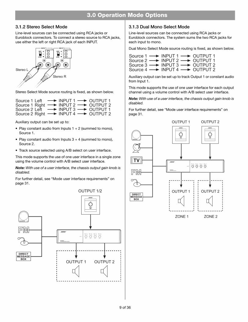
3.1.2 Stereo Select ModeLine-level sources can be connected using RCA jacks or Euroblock connectors. To connect a stereo source to RCA jacks, use either the left or right RCA jack of each INPUT.
Stereo Select Mode source routing is fixed, as shown below.
Auxiliary output can be set up to:
• Play constant audio from Inputs 1 + 2 (summed to mono), Source 1.
• Play constant audio from Inputs 3 + 4 (summed to mono), Source 2.
• Track source selected using A/B select on user interface.
This mode supports the use of one user interface in a single zone using the volume control with A/B select user interface.
Note: With use of a user interface, the chassis output gain knob is disabled.
For further detail, see “Mode user interface requirements” on page 31.
3.1.3 Dual Mono Select ModeLine-level sources can be connected using RCA jacks or Euroblock connectors. The system sums the two RCA jacks for each input to mono.
Dual Mono Select Mode source routing is fixed, as shown below.
Auxiliary output can be set up to track Output 1 or constant audio from Input 1.
This mode supports the use of one user interface for each output channel using a volume control with A/B select user interface.
Note: With use of a user interface, the chassis output gain knob is disabled.
For further detail, see “Mode user interface requirements” on page 31.
9 of 36
4.0 Install and Wiring.fm Page 10 Monday, February 12, 2007 8:52 AM
4.0 Hardware Installation
4.1 IntroductionThis section provides instructions for installing and wiring the Bose FreeSpace® DXA 2120 Digital Mixer/Amplifier.
4.2 Included accessories• 3-terminal input connectors (4) – For wiring
equipment to the MIC/LINE INPUT Euroblock jacks.
• 4-terminal input connectors (2) – For wiring equipment to the single PAGE INPUT and single DIRECT INPUT jacks.
• 6-terminal input connector (1) – For wiring to the REMOTE jack.
• 5-terminal output connectors (2) with screw caps – For wiring speakers to OUTPUT 1 and OUTPUT 2.
• 3-terminal output connector (1) – For wiring to the AUX OUTPUT jack.
• Rubber feet (4) – For installing the chassis on a level surface.
• Rack ears with
Rack ears (6) #8-32 x 1/2 in
mounting hardware (2) – For installing the mixer/amplifier chassis (2U) in a rack.
4.3 Placement guidelinesFor placement of the mixer/amplifier chassis, keep the following in mind:
• Make sure that air can circulate freely behind, beside, and above the chassis for adequate ventilation. There are intake vents on the sides and an exhaust vent on the back of the unit. Do not cover or block the vents.
• Make sure the chassis is protected from heat and kept away from direct heat sources, such as heating vents and radiators.
CAUTION: Do not allow the chassis to exceed the maximum operating temperature of 50° C (122° F). Be aware of conditions in an enclosed rack that may increase the temperature above room-ambient conditions.
4.4 Shelf mounting the chassisThe Bose® FreeSpace® DXA 2120 Digital Mixer/Amplifier has rubber feet for use when positioning the chassis on a shelf or counter top. They help to protect the surface that supports the unit and to prevent chassis movement. Be sure to follow the “Placement guidelines” previously described when choosing a location for the unit.
1. Place the mixer/amplifier upside-down on a solid, level surface on a protective covering to avoid scratching the top of the chassis.
2. Insert the supplied rubber feet to the four existing holes on the bottom of the chassis. Use a screwdriver to push the locking pins fully into the chassis, securing the feet.
Note: The rubber feet may be removed by inserting a screwdriver into the screw and turning counterclockwise until the screw backs out of the hole.
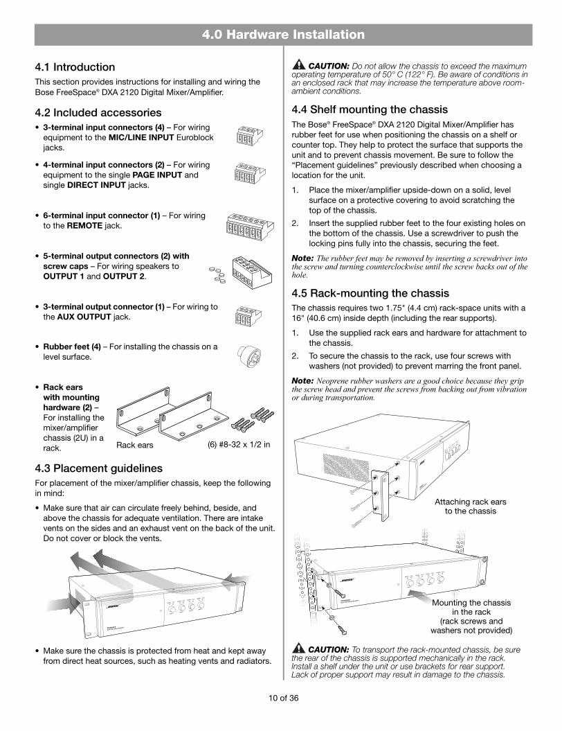
4.5 Rack-mounting the chassisThe chassis requires two 1.75" (4.4 cm) rack-space units with a 16" (40.6 cm) inside depth (including the rear supports).
1. Use the supplied rack ears and hardware for attachment to the chassis.
2. To secure the chassis to the rack, use four screws with washers (not provided) to prevent marring the front panel.
Note: Neoprene rubber washers are a good choice because they grip the screw head and prevent the screws from backing out from vibration or during transportation.
Attaching rack earsto the chassis
Mounting the chassis in the rack
(rack screws and washers not provided)
CAUTION: To transport the rack-mounted chassis, be sure the rear of the chassis is supported mechanically in the rack. Install a shelf under the unit or use brackets for rear support. Lack of proper support may result in damage to the chassis.
10 of 36
4.0 Hardware Installation
4.0 Install and Wiring.fm Page 11 Monday, February 12, 2007 8:52 AM
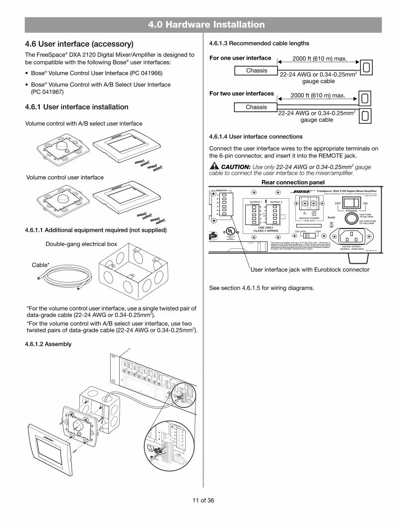
4.6 User interface (accessory)The FreeSpace® DXA 2120 Digital Mixer/Amplifier is designed to be compatible with the following Bose® user interfaces:
• Bose® Volume Control User Interface (PC 041966)
• Bose® Volume Control with A/B Select User Interface (PC 041967)
4.6.1 User interface installation
Volume control user interface
Volume control with A/B select user interface
4.6.1.1 Additional equipment required (not supplied)
Cable*
Double-gang electrical box
*For the volume control user interface, use a single twisted pair of data-grade cable (22-24 AWG or 0.34-0.25mm2).*For the volume control with A/B select user interface, use two twisted pairs of data-grade cable (22-24 AWG or 0.34-0.25mm2).
4.6.1.2 Assembly
4.6.1.3 Recommended cable lengths
Chassis
2000 ft (610 m) max.For one user interface
Chassis22-24 AWG or 0.34-0.25mm2
gauge cable
For two user interfaces 2000 ft (610 m) max.
22-24 AWG or 0.34-0.25mm2
gauge cable
4.6.1.4 User interface connections
Connect the user interface wires to the appropriate terminals on the 6-pin connector, and insert it into the REMOTE jack.
CAUTION: Use only 22-24 AWG or 0.34-0.25mm2 gauge cable to connect the user interface to the mixer/amplifier
Rear connection panel
User interface jack with Euroblock connector
.
See section 4.6.1.5 for wiring diagrams.
11 of 36
4.0 Hardware Installation
4.0 Install and Wiring.fm Page 12 Monday, February 12, 2007 8:52 AM
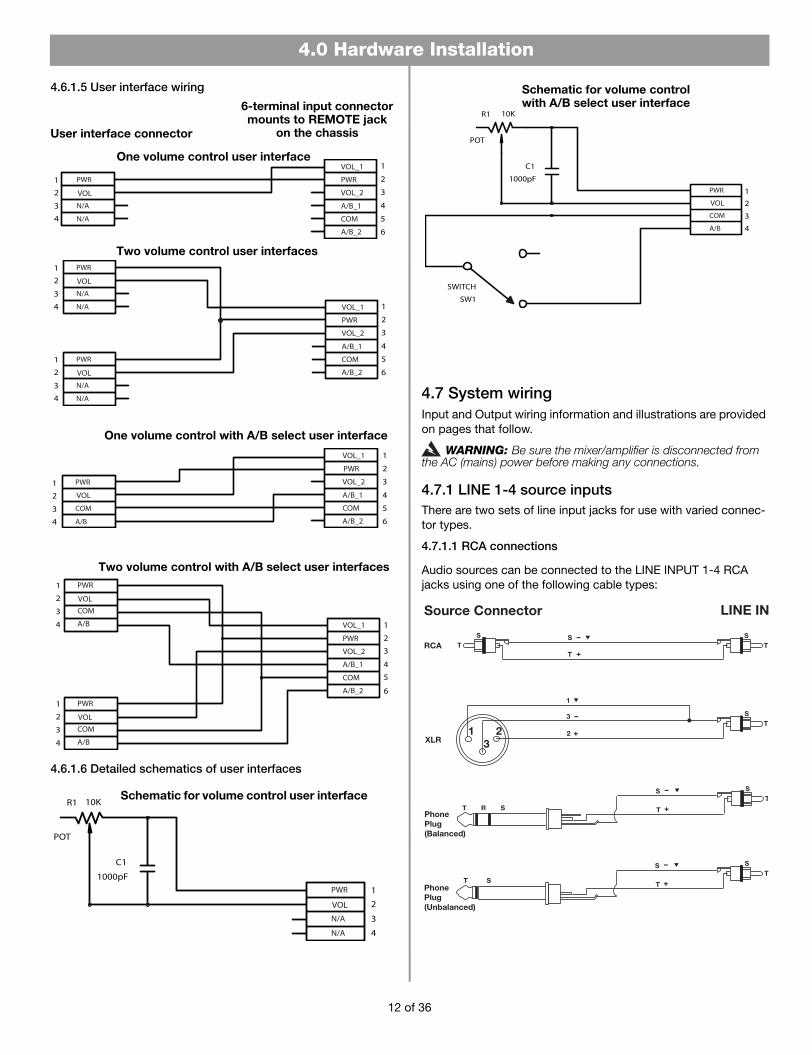
4.6.1.5 User interface wiring
Two volume control with A/B select user interfaces
One volume control with A/B select user interface
Two volume control user interfaces
One volume control user interface
User interface connector
6-terminal input connector mounts to REMOTE jack
on the chassis
4.6.1.6 Detailed schematics of user interfaces
Schematic for volume control user interface
Schematic for volume control with A/B select user interface
4.7 System wiringInput and Output wiring information and illustrations are provided on pages that follow.
WARNING: Be sure the mixer/amplifier is disconnected from the AC (mains) power before making any connections.
4.7.1 LINE 1-4 source inputsThere are two sets of line input jacks for use with varied connec-tor types.
4.7.1.1 RCA connections
Audio sources can be connected to the LINE INPUT 1-4 RCA jacks using one of the following cable types:
XLR
RCAT
ST
S
TS
1 23
2
3T
S
1
Source Connector LINE IN
T
ST
S
PhonePlug(Unbalanced)
T
S
T ST
S
PhonePlug(Balanced)
T R S
12 of 36
4.0 Hardware Installation
4.0 Install and Wiring.fm Page 13 Monday, February 12, 2007 8:52 AM
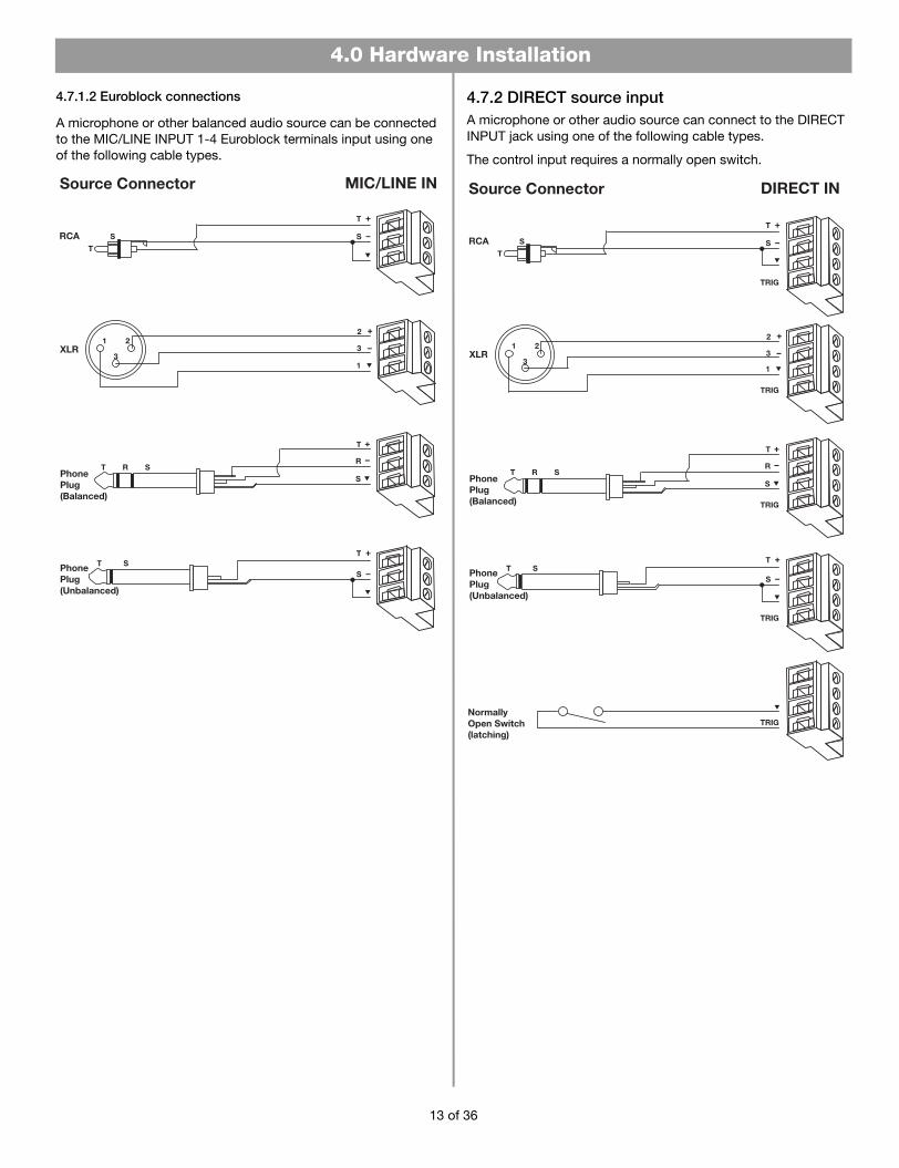
4.7.1.2 Euroblock connections
A microphone or other balanced audio source can be connected to the MIC/LINE INPUT 1-4 Euroblock terminals input using one of the following cable types.
XLR3
1
2
3
PhonePlug(Balanced)
T R S
T
R
S
RCAT
S
Source Connector MIC/LINE IN
1 2
PhonePlug(Unbalanced)
T
S
T
S
T S
4.7.2 DIRECT source inputA microphone or other audio source can connect to the DIRECT INPUT jack using one of the following cable types.
The control input requires a normally open switch.
NormallyOpen Switch(latching)
Source Connector DIRECT IN
XLR3
1
2
3
PhonePlug(Balanced)
T R S
T
R
S
RCAT
S
1 2
PhonePlug(Unbalanced)
T
S
T
S
T S
TRIG
TRIG
TRIG
TRIG
TRIG
13 of 36
4.0 Hardware Installation
4.0 Install and Wiring.fm Page 14 Monday, February 12, 2007 8:52 AM
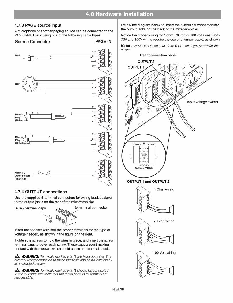
4.7.3 PAGE source inputA microphone or another paging source can be connected to the PAGE INPUT jack using one of the following cable types.
NormallyOpen Switch(latching)
XLR3
1
2
3
PhonePlug(Balanced)
T R S
T
R
S
RCAT
S
1 2
PhonePlug(Unbalanced)
T
S
T
S
T S
PTT
PTT
PTT
PTT
PTT
4.7.4 OUTPUT connectionsUse the supplied 5-terminal connectors for wiring loudspeakers to the output jacks on the rear of the mixer/amplifier.
5-terminal connectorScrew terminal caps
Insert the speaker wire into the proper terminals for the type of voltage needed, as shown in the figure on the right.
Tighten the screws to hold the wires in place, and insert the screw terminal caps to cover each screw. These caps prevent making contact with the screws, which could cause an electrical shock.
WARNING: Terminals marked with are hazardous live. The external wiring connected to these terminals should be installed by an instructed person.
WARNING: Terminals marked with should be connected to the loudspeakers such that the metal parts of its terminal are inaccessible.
Follow the diagram below to insert the 5-terminal connector into the output jacks on the back of the mixer/amplifier.
Notice the proper wiring for 4 ohm, 70 volt or 100 volt uses. Both 70V and 100V wiring require the use of a jumper cable, as shown.
Note: Use 12 AWG (4 mm2) to 20 AWG (0.5 mm2) gauge wire for the jumper.
Rear connection panel
Input voltage switch
4 Ohm wiring
70 Volt wiring
100 Volt wiring
OUTPUT 1
OUTPUT 2
OUTPUT 1 and OUTPUT 2
14 of 36
4.0 Hardware Installation
4.0 Install and Wiring.fm Page 15 Monday, February 12, 2007 8:52 AM
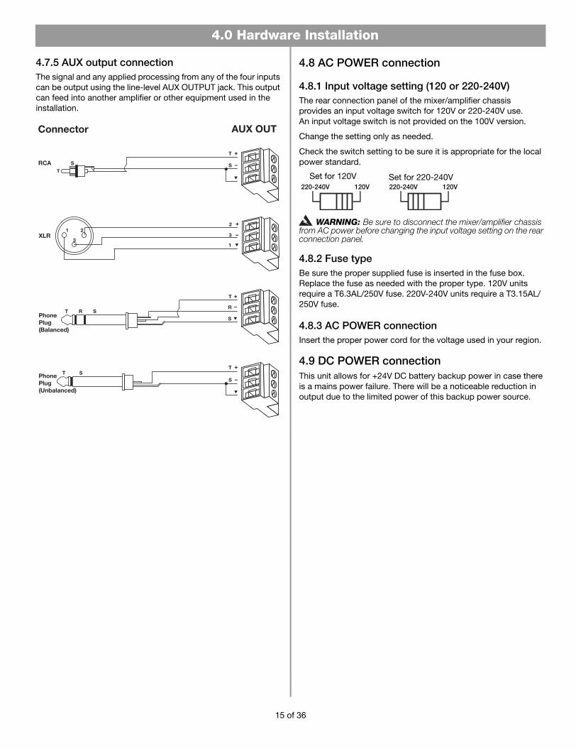
4.7.5 AUX output connectionThe signal and any applied processing from any of the four inputs can be output using the line-level AUX OUTPUT jack. This output can feed into another amplifier or other equipment used in the installation.
Connector AUX OUT
XLR3
1
2
3
PhonePlug(Balanced)
T R S
T
R
S
RCAT
S
1 2
PhonePlug(Unbalanced)
T
S
T
S
T S
4.8 AC POWER connection
4.8.1 Input voltage setting (120 or 220-240V)The rear connection panel of the mixer/amplifier chassis provides an input voltage switch for 120V or 220-240V use. An input voltage switch is not provided on the 100V version.
Change the setting only as needed.
Check the switch setting to be sure it is appropriate for the local power standard.
Set for 120V Set for 220-240V
WARNING: Be sure to disconnect the mixer/amplifier chassis from AC power before changing the input voltage setting on the rear connection panel.
4.8.2 Fuse typeBe sure the proper supplied fuse is inserted in the fuse box. Replace the fuse as needed with the proper type. 120V units require a T6.3AL/250V fuse. 220V-240V units require a T3.15AL/250V fuse.
4.8.3 AC POWER connectionInsert the proper power cord for the voltage used in your region.
4.9 DC POWER connectionThis unit allows for +24V DC battery backup power in case there is a mains power failure. There will be a noticeable reduction in output due to the limited power of this backup power source.
15 of 36

5.0 Setup.fm Page 16 Monday, February 12, 2007 8:54 AM
5.0 System Setup
5.1 System setup introductionThis section provides instructions on adjusting system settings for preferred operation. To make these settings, the system must be connected to power and the POWER switch set to ON.
POWER switch
POWER LED
Rear connection panel
AC power cordjack
Front control panel
Note: When the system is unplugged, or if a power loss occurs, these system settings are retained in flash memory. However, continuous system operation during a power loss requires the use of an optional backup power source.
5.2 System setup procedureWhen the unit is on, the POWER LED lights. Opening the front control compartment gives you access to the LCD and control buttons. The LCD displays the product model name at startup.
Arrow buttons
SELECT button
Front control compartment
• If the system is locked, simultaneously press the left and right arrow buttons and hold for five seconds. Lockout Off appears.
• When the system is unlocked, you can navigate to system setup options.
• Use the SELECT button to activate a menu option and to confirm a new setting.
• Use the arrow buttons to the right of the LCD to move forward, back, up, and down through menus.
5.2.1 Selecting an operation modeThe setting menus available depend on the mode of operation you choose. Use the right arrow button to enter the mode menu. Then use the up or down arrows to select the mode you want. Choose from:
• Mixer Mode: The system can mix up to four mic/line inputs to each of the two output channels for use in one or two zones.
• Stereo Select Mode: With up to two stereo sources connected and using both output channels, the system provides stereo sound to a single output zone.
• Dual Mono Select Mode: With two input sources connected to each of the two output channels, the system provides audio in two zones.
• Utility: Includes system lockout, an option to restore all settings to the factory defaults, and the ability to view firmware and EQ versions.
To confirm your selection, press the SELECT button. An asterisk (*) appears to the left of the selection made.
5.2.2 Setting the options for that mode There are several ways to change settings and particular buttons to use for each type of setting. Such as:
• To adjust Input Vol Lvl, use the knobs on the mixer/amplifier front panel only. The level that is set appears in the menu field, but cannot be changed in the menu.
• For Output Vol Lvl, adjust the gain knobs for output, located in the front control compartment.
• For Output Bass Lvl and Output Treb Lvl, turn the gain screws for bass and treble, located in the front control compartment.
• For Page Vol Lvl, use the PAGE GAIN knob, located in the front control compartment.
• To change Adj menu fields:1. Activate the field by pressing SELECT.
2. Use the up or down arrow to adjust the value.
3. Press SELECT to confirm the setting and move on.
Note: After a 45 second pause (with no activity), the system resets to the initial menu for the chosen mode.
16 of 36

5.0 System Setup
5.0 Setup.fm Page 17 Monday, February 12, 2007 8:54 AM
5.3 Mixer Mode settings Here is an overview of common steps to follow in setting up the Mixer Mode:
A. Choose this mode.
B. Set up inputs.
C. Set up outputs.
D. Choose EQ settings.
E. Set up Page Input, if applicable.
F. Set up Direct Input, if applicable.
G. Set up Master Volume, if applicable.
Setup menus unfold as you move right to the options provided, as shown.
5.3.1 A reminder: the settings process• For various adjustments (designated by Adj) use these steps:
1. Press SELECT to activate the Adj field.
2. Using the up or down arrow, adjust the value.
3. Press SELECT to confirm the setting and move on.
• For level changes (designated by Lvl), use front panel controls as shown.
• To change Input Vol Lvl, use:
• To change Output Vol Lvl, use:
• To change Output Bass Lvl and Output Treb Lvl, use a screwdriver to turn:
• To change Page Vol Lvl, use:
AChoose Mixer Mode
Press SELECT ( ) to confirm the mode selection. An asterisk (*) marks the selection made.
Bnext page
Cnext page
Dpage 19
Epage 20
Fpage 21
G page 21
17 of 36

5.0 System Setup
5.0 Setup.fm Page 18 Monday, February 12, 2007 8:54 AM
• For Input Vol Lvl
• For Input Bass Adj and Input Treb Adj Adjust the value to +/-6 dB in increments of .5 dB.
• For AGCEnable Choose N (no) or Y (yes).
BMixer Input Set-up
Select each Input that has a source connected (1, 2, 3, & 4).
CMixer Output Set-up
• For Input Mix Choose N (no) or Y (yes).
• For Output Vol Lvl
• For Output Bass Lvl and Input Treb Lvl Adjust the value to +/-6 dB in increments of .5 dB.
Select each Output to be used (1, 2, or Auxout).
Note: AGC defaults to N. AGC is recommended for use with low-level sources (i.e. microphone with low sensitivity).
18 of 36

5.0 System Setup
5.0 Setup.fm Page 19 Monday, February 12, 2007 8:54 AM
Select each Output to be used (1, 2, or Auxout).
• For Spkr EQ Move up or down to choose the EQ setting needed. An asterisk (*) marks the selection made.
• For Dynamic EQ Enable Choose N (no) or Y (yes).
Note: Dynamic EQ maintains tonal balance at all listening levels. The equalization adjusts automatically for the output level setting.
Mixer EQ Set-up D
19 of 36
5.0 System Setup
5.0 Setup.fm Page 20 Monday, February 12, 2007 8:54 AM
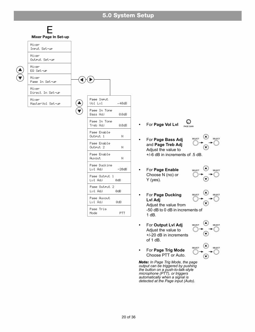
Mixer Page In Set-up E
• For Page Vol Lvl
• For Page Bass Adj and Page Treb Adj Adjust the value to +/-6 dB in increments of .5 dB.
• For Page Enable Choose N (no) or Y (yes).
• For Page Ducking Lvl Adj Adjust the value from -50 dB to 0 dB in increments of 1 dB.
• For Output Lvl Adj Adjust the value to +/-20 dB in increments of 1 dB.
• For Page Trig Mode Choose PTT or Auto.
Note: In Page Trig Mode, the page output can be triggered by pushing the button on a push-to-talk-style microphone (PTT), or triggers automatically when a signal is detected at the Page input (Auto).
20 of 36

5.0 System Setup
5.0 Setup.fm Page 21 Monday, February 12, 2007 8:54 AM
• For Output Linked Choose N (no) or Y (yes).
Note: Y links Output 1 and Output 2 gains for control using the Output 1 gain knob.
• For Vol Adj Adjust the value from -40 dB to +10 dB in increments of 1 dB.
• For Bass Adj and Treb Adj Adjust the value to +/-6 dB in increments of .5 dB.
Mixer Direct In Set-upF
Mixer Direct In Set-upF
Mixer Master Vol Set-upG
21 of 36

5.0 System Setup
5.0 Setup.fm Page 22 Monday, February 12, 2007 8:54 AM
5.4 Stereo Select Mode settings Here is an overview of common steps to follow in setting up the Stereo Select Mode:
A. Choose this mode.
B. Set up inputs.
C. Set up outputs.
D. Choose EQ settings.
E. Set up Page Input, if applicable.
F. Set up Direct Input, if applicable.
Setup menus unfold as you move right to the options provided, as shown.
5.4.1 Remember: for adjustments, use three steps• For various adjustments (designated by Adj), use these steps:
1. Press SELECT to activate the Adj field.
2. Using the up or down arrow, adjust the value.
3. Press SELECT to confirm the setting and move on.
• For level changes (designated by Lvl), use front panel controls as shown.
• To change Input Vol Lvl, use:
• To change Output Vol Lvl, use:
• To change Output Bass Lvl and Output Treb Lvl, use a screwdriver to turn:
• To change Page Vol Lvl, use:
22 of 36
Press SELECT ( ) to confirm the mode selection. An asterisk (*) marks the selection made.
Bnext page
Cnext page
Dpage 24
Epage 24
Fpage 25
Choose Stereo Select ModeA
23 of 36
5.0 System Setup
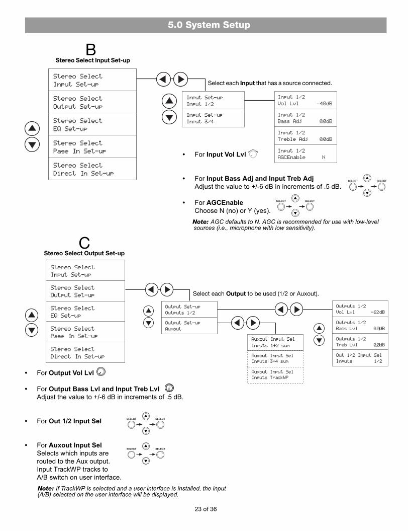
BStereo Select Input Set-up
Select each Input that has a source connected.
CStereo Select Output Set-up
Select each Output to be used (1/2 or Auxout).
• For Input Vol Lvl
• For Input Bass Adj and Input Treb Adj Adjust the value to +/-6 dB in increments of .5 dB.
• For AGCEnable Choose N (no) or Y (yes).
Note: AGC defaults to N. AGC is recommended for use with low-level sources (i.e., microphone with low sensitivity).
• For Output Vol Lvl
• For Output Bass Lvl and Input Treb Lvl Adjust the value to +/-6 dB in increments of .5 dB.
• For Out 1/2 Input Sel
• For Auxout Input Sel Selects which inputs are routed to the Aux output. Input TrackWP tracks to A/B switch on user interface.Note: If TrackWP is selected and a user interface is installed, the input (A/B) selected on the user interface will be displayed.
5.0 Setup.fm Page 23 Monday, February 12, 2007 8:54 AM

24 of 36
5.0 System Setup
• For Page Vol Lvl
• For Page Bass Adj and Page Treb Adj Adjust the value to +/-6 dB in increments of .5 dB.
• For Page Enable Choose N (no) or Y (yes).
• For Page Ducking Lvl Adj Adjust the value from -50 dB to 0 dB in increments of 1 dB.
• For Output Lvl Adj Adjust the value to +/-20 dB in increments of 1 dB.
• For Page Trig Mode. Choose PTT or Auto.Note: In Page Trig Mode, the page output can be triggered by pushing the button on a push-to-talk-style microphone (PTT), or triggers automatically when a signal is detected at the Page input (Auto).
Stereo Select EQ Set-up
Stereo Select Page In Set-upE
• For Dynamic EQ Enable Choose N (no) or Y (yes).
Note: Dynamic EQ maintains tonal balance at all listening levels. The equalization adjusts automatically for the output level setting.
• For Spkr EQ Move up or down to choose the EQ setting needed. An asterisk (*) marks the selection made
D
5.0 Setup.fm Page 24 Monday, February 12, 2007 8:54 AM

5.0 System Setup
5.0 Setup.fm Page 25 Monday, February 12, 2007 8:54 AM
Stereo Select Direct in Set-upF
• For Vol Adj Adjust the value from -40 dB to +10 dB in increments of 1 dB.
• For Bass Adj and Treb Adj Adjust the value to +/-6 dB in increments of .5 dB.
25 of 36

5.0 System Setup
5.0 Setup.fm Page 26 Monday, February 12, 2007 8:54 AM
5.5 Dual Mono Select Mode settings Here is an overview of common steps to follow in setting up the Dual Mono Select Mode:
A. Choose this mode.
B. Set up inputs.
C. Set up outputs.
D. Choose EQ settings.
E. Set up Page Input, if applicable.
F. Set up Direct Input, if applicable.
Setup menus unfold as you move right to the options provided, as shown.
5.5.1 Remember: for adjustments, use three steps• For various adjustments (designated by Adj), use these steps:
1. Press SELECT to activate the Adj field.
2. Using the up or down arrow, adjust the value.
3. Press SELECT to confirm the setting and move on.
• For level changes (designated by Lvl), use front panel controls as shown.
• To change Input Vol Lvl, use:
• To change Output Vol Lvl, use:
• To change Output Bass Lvl and Output Treb Lvl, use a screwdriver to turn:
• To change Page Vol Lvl, use:
AChoose Dual Mono Mode
Press SELECT ( ) to confirm the mode selection.
An asterisk (*) marks the selection made.
Bnext page
Cnext page
Dpage 28
Epage 28
Fpage 29
26 of 36

5.0 System Setup
5.0 Setup.fm Page 27 Monday, February 12, 2007 8:54 AM
27 of 36
• For Input Vol Lvl
• For Input Bass Adj and Input Treb Adj Adjust the value to +/-6 dB in increments of .5 dB.
• For AGCEnable Choose N (no) or Y (yes).
Note: AGC defaults to N. AGC is recommended for use with low-level sources (i.e., microphone with low sensitivity).
BDual Mono Select Input Set-up
Select each Input that has a source connected (1, 2, 3 & 4).
CDual Mono Select Output Set-up
Select each Output to be used (1, 2, or Auxout).
• For Output Vol Lvl
• For Output Bass Lvl and Input Treb Lvl Adjust the value to +/-6 dB in increments of .5 dB.
• For Out 1 and Out 2 Input Sel
• For Auxout Input Sel Selects which inputs are routed to the Aux output. Input TrackWP tracks to A/B switch on user interface.Note: If TrackWP is selected and a user interface is installed, the input (A/B) selected on the user interface will be displayed.
5.0 System Setup
5.0 Setup.fm Page 28 Monday, February 12, 2007 8:54 AM
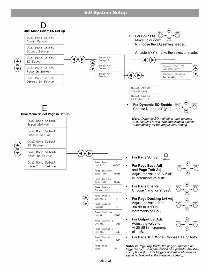
Dual Mono Select EQ Set-up
Dual Mono Select Page in Set-upE
D
• For Dynamic EQ Enable Choose N (no) or Y (yes).
Note: Dynamic EQ maintains tonal balance at all listening levels. The equalization adjusts automatically for the output level setting.
• For Spkr EQ Move up or down to choose the EQ setting needed. An asterisk (*) marks the selection made.
• For Page Vol Lvl
• For Page Bass Adj and Page Treb Adj Adjust the value to +/-6 dB in increments of .5 dB.
• For Page Enable Choose N (no) or Y (yes).
• For Page Ducking Lvl Adj Adjust the value from -50 dB to 0 dB in increments of 1 dB.
• For Output Lvl Adj Adjust the value to +/-20 dB in increments of 1 dB.
• For Page Trig Mode. Choose PTT or Auto.
Note: In Page Trig Mode, the page output can be triggered by pushing the button on a push-to-talk-style microphone (PTT), or triggers automatically when a signal is detected at the Page input (Auto).
28 of 36
5.0 System Setup
5.0 Setup.fm Page 29 Monday, February 12, 2007 8:54 AM
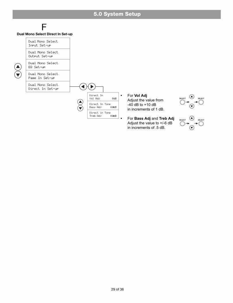
Dual Mono Select Direct In Set-upF
• For Vol Adj Adjust the value from -40 dB to +10 dB in increments of 1 dB.
• For Bass Adj and Treb Adj Adjust the value to +/-6 dB in increments of .5 dB.
29 of 36

5.0 System Setup
5.0 Setup.fm Page 30 Monday, February 12, 2007 8:54 AM
5.6 Overview of Utility Mode settingsIn Utility Mode, there are two global system options: Lockout and Restore Factory Defaults. Also, current system firmware and EQ versions are viewable.
The Lockout option allows the system settings to be locked to prevent unwanted changes. This Lockout function can be disengaged by pressing and holding the left and right arrows simultaneously for five seconds. Lockout Off will appear.
The Restore Factory Defaults option allows all software- selectable settings to be set back to the original factory settings. See “Factory Default Settings” on page 33.
Note: Settings made using a control knob are not reset.
Choose Utility Mode
30 of 36
• For FW Version Version number of system firmware will be displayed.
• For EQ Version Version number of loudspeaker EQ set will be displayed.

31 of 36
6.0 User Interfaces
6.1 User interface useBose has designed two user interface controls for use with the FreeSpace® DXA 2120 Digital Mixer/Amplifier.
• Bose volume control user interface is for use when only volume control is required.
• Bose volume control with A/B select user interface is for use in Stereo Select Mode or Dual Mono Select Mode when an output provides audio from more than one input source.
Connection of one or two user interfaces to the chassis disables the output gain knob for the output assigned to that user interface.
6.1.1 Mode user interface requirements• For Mixer Mode:
Sources can be routed to either or both outputs. Use of one or two volume control user interfaces is optional. No user inter-faces are required.
• For Stereo Select Mode: Source routing is fixed. This mode supports the use of one user interface in a single zone. Use the volume control with A/B select user interface.
• For Dual Mono Select Mode: Source routing is fixed. This mode supports the use of one user interface for each output channel. Use two volume controls with A/B select user interfaces.
6.1.1.1 Mixer Mode user interface application
Adjusts the volume
of the OUTPUT 1 audio mix
GAIN knobsdisabled withuser interface
use
Adjusts the volume
of the OUTPUT 2 audio mix
Note: Output 1 gain can be configured as the Master Volume, controlling Output 1 and Output 2 gains simultaneously using the MasterVol Linked menu option.
6.1.1.2 Stereo Select Mode user interface application
Adjusts the volume
Selects one source (A) or the other (B)
in the single zone
GAIN knobsdisabled withuser interface
use
6.1.1.3 Dual Mono Select Mode user interface application
Adjusts the volume
Selects one source (A) or the other (B)
in Zone 2
Adjusts the volume
Selects one source (A) or the other (B)
in Zone 1
GAIN knobsdisabled withuser interface
use
6.0 User Interface Use.fm Page 31 Monday, February 12, 2007 8:55 AM

32 of 36
7.0 Troubleshooting Table
No Power • Turn on power.• Make sure the power cord is plugged in.
Power is on, but no sound • Make sure the source is turned on.• Verify that there is an input signal from the source. The audio input signal indicator on
the front of the chassis should be green.• Check the output signal indicators on the system controls. If the LED is not lit (green),
the output levels may be too low.• Check the source routing.• Check the cable connections from the source to the chassis.• Verify the user interfaces are of the right type for the operating mode selected.
Power is on, but sound is low • Verify that the audio input indicator is lit (green). If it is not lit, increase the source output or increase the input gain.
Sound is distorted • Verify that the Input clipping indicators are not lit (red). If an LED is red, reduce the source output level or reduce the input gain.
• Verify that the Output clipping indicators are not lit (red). If one is red, but Input clip-ping LEDs are not, reduce the output gain.
• If the input source signal is clean when it enters the chassis and the Input and Output indicators are green, verify that the loudspeakers are not overdriven or damaged.
Unnatural sound • Verify that the correct EQ is selected for speakers connected to the Output channel.• Verify that the speakers are wired correctly (+ to + and - to -).
User interfaces do not operate properly
• Verify that the user interfaces are wired correctly and to the proper zone (if there is more than one zone).
• Check the wiring for breaks or shorts in the cable.• Verify the user interfaces are of the right type for the operating mode selected.
7.1 Technical assistanceIf you need further technical assistance, contact your local Bose® representative, or visit pro.Bose.com.
7.0 Trouble table.fm Page 32 Monday, February 12, 2007 9:08 AM

33 of 36
8.0 Reference
8.1 Factory Default Settings
Input 1 Bass 0 dB 0 dB 0 dB -6 dB ~ +6 dB
Treble 0 dB 0 dB 0 dB -6 dB ~ +6 dB
AGC Enable N N N
Input 2 Bass 0 dB 0 dB 0 dB -6 dB ~ +6 dB
Treble 0 dB 0 dB 0 dB -6 dB ~ +6 dB
AGC Enable N N N
Input 3 Bass 0 dB 0 dB 0 dB -6 dB ~ +6 dB
Treble 0 dB 0 dB 0 dB -6 dB ~ +6 dB
AGC Enable N N N
Input 4 Bass 0 dB 0 dB 0 dB -6 dB ~ +6 dB
Treble 0 dB 0 dB 0 dB -6 dB ~ +6 dB
AGC Enable N N N
Page Input Bass 0 dB 0 dB 0 dB -6 dB ~ +6 dB
Treble 0 dB 0 dB 0 dB -6 dB ~ +6 dB
Trigger Mode PTT PTT PTT
Page Ducking -20 dB -20 dB -20 dB -50 dB ~ 0 dB
Direct Input Volume 0 dB 0 dB 0 dB -40 dB ~ +10 dB
Bass 0 dB 0 dB 0 dB -6 dB ~ +6 dB
Treble 0 dB 0 dB 0 dB -6 dB ~ +6 dB
Miscellaneous Master Volume Linked N n/a n/a
Output 1 *Out 1/2 Input Sel (Stereo only) n/a *1/2 (1) n/a
Out 1 Input Sel (Dual Mono only) n/a n/a 1
Input Mix - Input 1 (Mixer only) Y n/a n/a
Input Mix - Input 2 (Mixer only) N n/a n/a
Input Mix - Input 3 (Mixer only) N n/a n/a
Input Mix - Input 4 (Mixer only) N n/a n/a
Spkr EQ Preset 01 80 Hz HPF 01 80 Hz HPF 01 80 Hz HPF
Dynamic EQ Enable N N N
Page Enable N N N
Page Level 0 dB 0 dB 0 dB -20 dB ~ +20 dB
Output 2 *Out 1/2 Input Sel (Stereo only) n/a *1/2 (2) n/a
Out 2 Input Sel (Dual Mono only) n/a n/a 3
Input Mix - Input 1 (Mixer only) Y n/a n/a
Input Mix - Input 2 (Mixer only) N n/a n/a
Input Mix - Input 3 (Mixer only) N n/a n/a
*These parameters are linked and displayed on the same menu screen. The numbers in parenthesis indicate which input is automati-cally selected and routed to the respective output.
Channel Parameter Mixer Stereo Dual Mono Parameter Range (if applicable)
Input Mix - Input 4 (Mixer only) N n/a n/a
Spkr EQ Preset 01 80 Hz HPF 01 80 Hz HPF 01 80 Hz HPF
Dynamic EQ Enable N N N
Page Enable N N N
Page Level 0 dB 0 dB 0 dB -20 dB ~ +20 dB
Auxout Auxout Input Sel (Stereo/Dual Mono) n/a 1+2 sum 1 Fixed
Auxout Input Mix - Input 1 (Mixer only) Y n/a n/a
Auxout Input Mix - Input 2 (Mixer only) N n/a n/a
Auxout Input Mix - Input 3 (Mixer only) N n/a n/a
Auxout Input Mix - Input 4 (Mixer only) N n/a n/a
Spkr EQ Preset 01 80 Hz HPF 01 80 Hz HPF 01 80 Hz HPF
Dynamic EQ Enable N N N
Page Enable N N N Page Level 0 dB 0 dB 0 dB -20 dB ~ +20 dB
8.0 Reference.fm Page 33 Monday, February 12, 2007 9:08 AM

36
©2007 Bose Corporation, The MountainFramingham, MA 01701-9168 USAAM298725 Rev.00 pro.Bose.com
E4 Back.fm Page 37 Monday, February 12, 2007 11:01 AM