
FreeDimension : Pioneering a New Approach to Surface Design
8
FreeDimension™ : Pioneering a New Approach to Surface Design Alyn Rockwood CTO FreeDesign Inc. In the beginning, Bezier, de Casteljau, Coons and other pioneers in CAD had a vision of providing designers and engineers a method to create shapes from curves that could be easily analyzed and manufactured with the computer. They recognized that designers conceptualized shape in terms of curves, and that the shape was some well-behaved surface that filled the void between the curves. The well-known Bezier and B-spline surface patches were a result. Using a few control points, the curves and slopes of the surface at the curves can be specified, yielding a smooth, intuitively defined surface patch. After four decades of research and development, current modeling technology is based on the NURBS surface, which is an extension of many of the older techniques like Bezier. Both Bezier and NURBS surfaces may be thought of as a sweep of curves. Take a flexible wire cable between your hands and imagine the surface swept out as you move the cable through space. You may deform the wire as you sweep. This is one way to understand what these surface patches are. With a few controls this sweep can be fully specified. Figure 1 illustrates. Figure 1. Designing a car with NURBS from Alias Studio tutorial. NURBS stands for Non-Uniform Rational B-Splines. B-splines are a polynomial form for which continuity between pieces of the curve is easy to ensure. It is the reason for
Transcript of FreeDimension : Pioneering a New Approach to Surface Design

FreeDimension™: Pioneering a New Approach to Surface Design
Alyn Rockwood CTO
FreeDesign Inc. In the beginning, Bezier, de Casteljau, Coons and other pioneers in CAD had a vision of providing designers and engineers a method to create shapes from curves that could be easily analyzed and manufactured with the computer. They recognized that designers conceptualized shape in terms of curves, and that the shape was some well-behaved surface that filled the void between the curves. The well-known Bezier and B-spline surface patches were a result. Using a few control points, the curves and slopes of the surface at the curves can be specified, yielding a smooth, intuitively defined surface patch. After four decades of research and development, current modeling technology is based on the NURBS surface, which is an extension of many of the older techniques like Bezier. Both Bezier and NURBS surfaces may be thought of as a sweep of curves. Take a flexible wire cable between your hands and imagine the surface swept out as you move the cable through space. You may deform the wire as you sweep. This is one way to understand what these surface patches are. With a few controls this sweep can be fully specified. Figure 1 illustrates.
Figure 1. Designing a car with NURBS from Alias Studio tutorial. NURBS stands for Non-Uniform Rational B-Splines. B-splines are a polynomial form for which continuity between pieces of the curve is easy to ensure. It is the reason for

their popularity. Rational B-splines main purpose is to define conics and quadrics exactly, i.e. spheres, cylinders, cones and so forth. Non-uniform B-splines allow the control points to have variable influence on the surface, and add some minimal design facility over “uniform” B-splines. Their real purpose is to give a modeling system closure. When a B-spline curve or surface is subdivided, as often done, the result is most likely to be non-uniform. Thus non-uniformity exists to allow this operation. NURBS dominate the freeform surface modeling world. NURBS became the standard for surface modeling in the 80’s, so that almost all surface modelers have some form or NURBS input and output. Supporting software also expects NURBS as input, whether it is analysis, rendering, milling, mold flow simulation or others. However, as with so many standards, the drive to make NURBS the standard may have been premature, if unavoidable. This assertion is justified by many instances where NURBS impose an unwarranted burden on the designer, solely because of the underlying mathematical structure. There are two other justifications for the claim that are deeper. They are that: (1) the pioneers’ original goal of designing with curves has never been completely fulfilled with NURBS, and (2) this goal was not exactly what designers were looking for in the first place. Let us start with the second justification. Ask any designer, stylist or engineer, whose task is to create a freeform shape, and they will tell you they think initially in terms of curves. The proverbial sketch of curves on a napkin (See Figure 2) has its legendary status exactly because it is so common in practice, and it is how designers think. In that regard the pioneers got it right. The problem with their approach was that it is not just any set of curves on the surface that designers employ when sketching shape; rather, it is the feature curves of the object that they envision. Look again at the crude sketch in Figure 2. The curves laid out represent salient features like boundaries, creases or highlights. In contrast, Figure 1 shows a model of a car, using a well-known “NURBS” modeler. Many of the curves have no design purpose; they exist only to support the underlying patches.
Figure 2. The napkin sketch – how designers think.

A Bezier or NURBS patch uses curves to design a patch, not an object. The patches must then be pieced together to form the object. The last point underpins the first assertion. Current modelers require the designer to layout a patch network as part of the creation of shape. This is also evident in Figure 1. A great deal of effort can be seen in laying out a patch network around the windshield pillar, for example. It takes talent and patience to reproduce that region with four-sided patches. The tutorial embodies this with the following associated language that is familiar practice for NURBS designers:
To create a single surface, select the 4 curves that bound the surface, and use menu to Create Surface. You will find some problem areas (like the triangle region on the left). You have to use your knowledge of how patches work and make your fixes
So we see that designing patches with curves is still a long way from designing an entire object with curves. There are other issues peculiar to NURBS modeling. One of those is the need to trim surface patches. A trimmed patch is one that includes a curve that dictates which part of the surface patch is ignored, i.e. trimmed. While most commercial modeling companies prefer to sell trimming as a positive attribute (it works with Boolean operations of unite and intersect), it should be regarded as a band-aid fix that creates a more complex data structure and considerably more expensive computations as each evaluation must be computed with respect to which side of the trim it is on. Trimmed boundaries are nearly impossible to join with tangency to other surfaces; they are typically used along kinks and sharp edges, created by the Booleans. Even then, they are likely to gap and require special “healing” operations. If there were an alternative to designing with Booleans, modelers would be happy to dump trimming. Another problem with NURBS is the so-called tartan plaid requirement. A NURBS surface requires that opposing boundary curves have the same number of control points, even if one side is simple and the other complex. The simple side must match the opposite one in complexity. Said another way, the parameterizations must match. Thus, the parameter lines running across the surface in both directions create a tartan plaid structure as in Figure 1. If the parameter lines diverge too much, unexpected behavior in the surface can follow. Again, advice from a NURBS modeling manual:
“…if the opposing sides are parallel, the surface will not twist and highlights will be clean. However, there are few surfaces with truly parallel opposing sides. The surfaces should maintain a parallel relation, but corrected visually in parts.” [Rhino]
Finally, we mention the T-junction problem. NURBS surface boundaries should form a cross “+” at the corners, i.e. every corner has four surfaces meeting at it. If this is not the case and, say, two surfaces meet a third in the middle of a boundary at a “T” it is difficult to maintain tangent or higher order continuity there. Some modelers have a melding

technique that allows T-junctions by approximately cleaning up the problems with a post-fix operation. Modelers have existed that overcame some of these issues. Early piece part modelers such as ROMULUS from Shape Data used canonical surfaces such as spheres, cylinders, cones, planes etc. with Booleans and then blended them together achieving some design ability as in Figure 3, but far from a conceptual modeler. Another modeler from Shape Data was REMUS, the first commercial recursive subdivision surface modeler. Conceptually, it works by successively chamfering a polyhedral mesh. If chamfered enough the mesh becomes smooth. In fact it generates B-spline surfaces, except at a few “extraordinary points,” which have a large number of converging patches around the point. These large numbers of patches, and the lack of higher order continuity at the extraordinary doomed the approach for precision CAD applications. Perhaps the closest attempt to a true curve based modeler, among the early modelers, was DESIGNBASE. It was based on multisided Gregory patches and therefore admitted a freeform curve network, not constrained as the NURBS modelers to rectangular crossing networks. However, N-sided Gregory patches consist of N rectangular Bezier patches that are blended at the boundaries and at a center point in the patch. If the patches are distorted too much then the “non-square” issues mentioned above arise. This constrains the patches and limits their usefulness somewhat; the designer must still design with patches, but to a lesser extent than with NURBS. We can reduce the modeling paradigms to 4 general types:
1. Boolean operations, also called CSG modeling. The designer positions primitives such as spheres, cylinders or torii and then either unites, or intersects them; or subtracts one from the other. This approach creates wide array of “engineering” objects
2. Recursive subdivision. In this method the designer manipulates polyhedra by extruding, splitting or combining faces as in Figure 4.. The resulting facetted object is then smoothed automatically. It is a quick and convenient way to create “organic” shapes. It is quite popular in animation, for instance.
3. Patch based modeling. This is the classic approach to freeform surface modeling. There are many supporting operations beyond manipulating points such as sweeps, spins and templates. As discussed it ultimately comes down to tiling the surface of the object with four-sided patches. It is widely used in aerospace, automotive, shipbuilding, consumer goods and package design where ad hoc techniques for each object have been highly developed.
4. Feature curve modeling. In this way of modeling the designer first creates the feature curves of the object. The surfaces automatically and intuitively fill the intervening surfaces, regardless of the number of sides; thus the focus shifts from creating patches to creating curves.

The first three methods above are in general use; there are many specific operations to enhance them, such blending and filleting, trimming, etc. The accomplished designer will use all approaches in combination, depending on what best fits the need. It is a toolbox approach to designer. Each of the three tools has a unique facility to design particular shapes. The fourth method has seen only limited acceptance, not because of the paradigm, but more because of the difficulty in implementing it. Recent research [Gao] has produced a new modeling system that uses N-sided Surfaces (NSS) to realize curve base modeling Figure 3 is a simple example. It shows the 3D model, which essentially uses as input the napkin curves of Figure 2. Look at it closely. The patches in it have far more irregular shapes than could be handled by NURBS. There are 3, 4, 5 and 6-sided patches and T-junctions, which arise naturally to fit the configuration indicated by the feature curves.
Figure 3. Three-D surface model of Figure 2. The new modeling system is called FreeDimension (FD) and offered currenty as a free Beta download by FreeDesign Inc. of Longmont, Colorado (See www.freedesign-inc.com). It is what is called technically as a transfinite interploation modeler. That simply means that the surface interpolates to given curves as opposed to points (finite interpolation). The NSS surface patches will pass through any number of user specified curves from 2 to N. Examples of 12-sided fillets are given. A single curve may form a boundary with many patches. In Figure 4 the feature line starts at the front of the hood, forms the roof line and ends at the trunk. In figure 6 it is blue and marked. A curve is
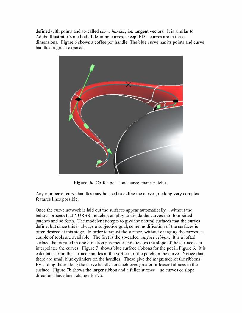
defined with points and so-called curve handes, i.e. tangent vectors. It is similar to Adobe Illustrator’s method of defining curves, except FD’s curves are in three dimensions. Figure 6 shows a coffee pot handle The blue curve has its points and curve handles in green exposed.
Figure 6. Coffee pot – one curve, many patches. Any number of curve handles may be used to define the curves, making very complex features lines possible. Once the curve network is laid out the surfaces appear automatically – without the tedious process that NURBS modelers employ to divide the curves into four-sided patches and so forth. The modeler attempts to give the natural surfaces that the curves define, but since this is always a subjective goal, some modification of the surfaces is often desired at this stage. In order to adjust the surface, without changing the curves, a couple of tools are available. The first is the so-called surface ribbon. It is a lofted surface that is ruled in one direction parameter and dictates the slope of the surface as it interpolates the curves. Figure 7 shows blue surface ribbons for the pot in Figure 6. It is calculated from the surface handles at the vertices of the patch on the curve. Notice that there are small blue cylinders on the handles. These give the magnitude of the ribbons. By sliding these along the curve handles one achieves greater or lessor fullness in the surface. Figure 7b shows the larger ribbon and a fuller surface – no curves or slope directions have been change for 7a.

Figure 7a. Surface ribbon controls slope. b. Changing magnitude of slope. The other basic surface manipulation tool is the surface handle. Like the curve handle it is a tangent vector, but this crosses the curve to determine the slope of the surface at the point of insertion. It influences the slope of the ribbon. If the surface handles are broken at their bases then the surface will crease. Figure 8 shows how this can be used to design a crease that dissipates to a smooth transitions along the hood and over the tire.
Figure 8. An automobile with creased surfaces controlled by surface handles.
These are the basics for the new design paradigm, that is, designing curves with points and curve handles; then refining the surface with ribbons and surface handles. It is simple to learn and to use. There are, of course, many supporting operations such as snapping handles to directions, display and camera operations, constraints, volumetrics, reflecting, global stretch operations, just to name a few. For designers accustomed to the older ways of modeling feature curves and ribbons represent a starkly different way of thinking, but refreshing and powerful. Designs come together rapidly with a very small number of inputs FreeDimension is a conceptual modeler, primarily for generating shapes. It does not attempt to handle all modeling operations such as photorealistic rendering, analyses, NC, etc. For this it outputs various polygon files and a B-spline approximation. In this sense it pays well with other modelers, while focusing on its strengths for initial design of shape, using curves and slopes. It is what those pioneers had imagined decades earlier.


