
Free Vibration and Bending Analysis of Uniformly...
59
Free Vibration and Bending Analysis of Uniformly Distributed Carbon Nanotube Composite Plate Using Finite Element Method Ajay Kumar Paswan
Transcript of Free Vibration and Bending Analysis of Uniformly...

Free Vibration and Bending Analysis of Uniformly
Distributed Carbon Nanotube Composite Plate Using
Finite Element Method
Ajay Kumar Paswan

Free Vibration and Bending Analysis of Uniformly
Distributed Carbon Nanotube Composite Plate Using
Finite Element Method
Thesis Submitted to
National Institute of Technology, Rourkela
for the award of the degree
of
Master of Technology
In Mechanical Engineering with Specialization
“Machine Design and Analysis”
by
Ajay Kumar Paswan
Roll No. 213me1383
Under the Supervision of
Prof. Subrata Kumar Panda
Department of Mechanical Engineering
National Institute of Technology Rourkela
Odisha (India) -769 008
May- 2015

NATIONAL INSTITUTE OF TECHNOLOGY
ROURKELA
CERTIFICATE
This is to certify that the work in this thesis entitled “Free Vibration and Bending
Analysis of Uniformly Distributed Carbon Nanotube Composite Plate Using Finite
Element Method ” by Mr. Ajay Kumar Paswan (213ME1383) has been carried out under
my supervision in partial fulfilment of the requirements for the degree of Master of
Technology in Mechanical Engineering with Machine Design and Analysis specialization
during session 2013 - 2015 in the Department of Mechanical Engineering, National Institute of
Technology, Rourkela.
To the best of my knowledge, this work has not been submitted to any other
University/Institute for the award of any degree or diploma.
Date: Prof. S. K. Panda
(Assistant Professor)
Dept. of Mechanical Engineering
National Institute of Technology
Rourkela-769008

IV
SELF DECLARATION
I, Mr Ajay Kumar Paswan, Roll No. 213ME1383, student of M. Tech (2013-15), Machine
Design and Analysis at Department of Mechanical Engineering, National Institute of
Technology Rourkela do hereby declare that I have not adopted any kind of unfair means
and carried out the research work reported in this thesis work ethically to the best of my
knowledge. If adoption of any kind of unfair means is found in this thesis work at a later
stage, then appropriate action can be taken against me including withdrawal of this thesis
work.
NIT Rourkela
25 may 2015
Ajay Kumar Paswan

V
ACKNOWLEDGEMENT
My first thanks are to the Almighty God, without whose blessings, I wouldn't have been
writing this “acknowledgments". I am extremely fortunate to be involved in an exciting
and challenging research project work on “Free Vibration and Bending Analysis of
Uniformly distributed Carbon Nanotube Composite Plate Using Finite Element
Method”. It has enriched my life, giving me an opportunity to work in a new
environment of ANSYS and LAMMPS. This project increased my thinking and
understanding capability as I started the project from scratch.
I would like to express my greatest gratitude to my supervisor Prof. S . K. Panda, for
his excellent guidance, valuable suggestions and endless support. He has not only been a
wonderful supervisor but also an honest person. I consider myself extremely lucky to be
able to work under guidance of such a dynamic personality. He is one of such genuine
person for whom my words will not be enough to express.
I would like to express my sincere thanks to Vishesh R. Kar, Vijay K. Singh and P.V.
Katariya, Kulmani Mehar (My seniors) and all my classmates for their precious
suggestions and encouragement to perform the project work. I am very much thankful to
them for giving their valuable time for me.
Finally, I express my sincere gratitude to my parents for their constant
encouragement and support at all phases of my life.
Ajay Kumar Paswan

VI
Abstract
In this work, free vibration and bending behaviour of uniformly distributed carbon nanotube
composite plate are analysed. The material properties of single-walled carbon nanotube
evaluated through molecular dynamics simulation using LAMMPS software. The effective
material properties of the composite plates are obtained using an extended rule of mixture. A
finite element model is developed for the single-walled carbon nanotube composite plate
using ANSYS Parametric Design Language (APDL) code in ANSYS environment. For the
discretization purpose, an eight-noded serendipity shell element is used from the ANSYS
library. Subsequently, the validation study is performed through the available published
literature. Finally, the parametric study is demonstrated by varying different material and
geometrical parameters for free vibration and bending responses of composite plate.
Keywords: Carbon Nanotubes, Composite plate, Molecular Dynamics, FEM, ANSYS.

VII
Contents
Title Page (I)
Certificate of Approval (III)
Self-Declaration (IV)
Acknowledgement (V)
Abstract (VI)
Contents (VII)
List of Symbols (XI)
List of Tables (XIV)
List of Figures (XV)
Chapter 3 General Mathematical Formulation 13-33
Chapter 1 Introduction 1-7
1.1 Overview 1-2
1.2 Types of CNTs 2-4
1.3 CNTs geometry 4-5
1.4 Applications of CNTs 5-6
1.5 Motivation of the Current Work 6 -7
1.6 Aim and Scope of the Present Thesis 7
Chapter 2 Literature Review 9-13

VIII
3.1 Molecular dynamics simulation 13-23
3.1.1 Structure of carbon nanotube 16-17
3.1.2 Force fields and total potential energy 17-23
3.2 Finite Element Method and ANSYS 18-23
3.3 Carbon nanotube composite plate. 24-26
3.4 Free vibration of CNT composite plate. 26-28
3.5 Bending analysis of CNT composite plate. 28-30
Chapter 4 Results and Discussion 31-40
4.1 Types of Carbon nanotube and Volume fraction
validation.
31
4.2 Evaluation of material properties of carbon nanotubes. 32
4.3 Numerical illustrations of bending analysis. 33
4.4 Numerical illustrations of free vibration analysis. 36
Chapter 5 Conclusions 41
Future Scope of the Research 42
References 43-47

IX
List of Symbols
Record of the symbols is defined as they occur in the thesis. Some of most common
symbols, which are used repeatedly, are listed below:
x1, y1, z1 Co-ordinate axis of plane
E1, E2 and E3 Young’s modulus
G12, G23 and G13 Shear modulus
12 , 23 and 13 Poison’s ratios
a, b and h Length, width and thickness of the plate
l Linear strain directions
Stress direction at mid-plane
Displacement vector
SK Spring constant of bonding stretching
K Force constant of bending
K Force constant of torsion
F Force on each atom
US.E. Strain energy

X
U Potential energy
Φ0 Ideal phase
0V Initial volume of CNTs
c ca Length of carbon atom
i jr andr Position vector
T Function of thickness co-ordinate
Thermal expansion co-efficient
Density of the material
T Kinetic energy
a/h Thickness ratio
R/a Curvature ratio
E1/E2 Modular ratio
Abbreviation
APDL ANSYS parametric design language
SSSS All edges simply supported
CCCC All edges clamped
HHHH All edges hinged
LAMMPS Large-scale atomic molecular massively parallel simulation

XI
VMD Visualisation molecular dynamics
Eq. Equation
GPa Giga Pascal
MPa Mega pascal
Nm Nano mete

xii
List of Tables
Table No
Page No.
1 The comparison of non-dimensional elastic modulus for different
volume fraction.
31
2 The comparison of material properties in molecular dynamics. 32
3 The material properties of (10, 10) SWCNT. 33
4 The non-dimensional central deflection for different thickness ratio
(a/h) validation using volume fraction. (SSSS).
34
5 The non-dimensional central deflection for different thickness ratio
(a/h) using volume fraction. (a) CCCC.
35
6 The non-dimensional central deflection for different thickness ratio
(a/h) using volume fraction. (b) SCSC.
36
7 The non-dimensional fundamental frequency for different thickness
ratio validation using volume fraction. (SSSS).
37
8 The non-dimensional fundamental frequency for different thickness
ratio using volume fraction. (a) CCCC.
38
9 The non-dimensional fundamental frequency for different thickness
ratio using volume fraction. (b) SCSC.
39

xiii
List of Figures
Figure No. Page No.
1 Volume fraction of reinforcement (fiber) 2
2 Types of carbon nanotube. 4
3 Arrangement of carbon nanotubes (CNTs) for armchair, zig-zag and
chiral.
5
4 Interatomic interaction in molecular dynamics notion. 14
5 Boundary loading conditions for SWCNT armchair (10,10). 15
6 The graphite plane of nanotube surface coordinates. 16
7 Solid and Hollow CNTs through MD. 23
8 Shell 281element description. 25
9 Carbon nanotube reinforced composites plate. 28
10 Variation of elastic modulus for different types of fibres 32
11 The effect of thickness ratio on non-dimensional central
deflection(SSSS).
34
12 The effect of thickness ratio on non-dimensional central
deflection.(CCCC)
35
13 The effect of thickness ratio on non-dimensional central deflection.
(SCSC)
36
14 The effect of thickness ratio on non-dimensional fundamental
frequency.(SSSS)
37
15 The effect of thickness ratio on non-dimensional fundamental
frequency.(CCCC)
38
16 The effect of thickness ratio on non-dimensional fundamental
frequency.(SCSC)
39

1
CHAPTER 1
INTRODUCTION
1.1 Overview
Composite materials are defined as a group of two or more materials on a macroscopic scale.
These are always used because of its some unique properties like stiffness, strength, light weight,
corrosion resistance, thermal properties, and wear resistance. Composites have two constituent
elements namely, reinforcement (fibre) and matrix. The fibres are used in modern composites
because of its high specific mechanical properties compared to those of old-style bulk materials.
The reinforcement (fibre) is categorised as continuous fibre, short fibre and particulate fibre
depending upon the shape, orientation and chemical nature. Orientation fibres are used in
different angles. From the few decades, carbon and graphite are the common fibre materials used
by many weight complex industries. Matrix acts as a bonding element that shields fibre from
external break or damage. The main function of the matrix is to distribute and transfer the load to
the fibres or reinforcements. There are three types of matrix. Metal matrix composites (MMCs),
ceramic matrix composites (CMCs) and polymer matrix composites (PMCs) are the commonly
used material for matrix phase. The transformation of load is determined by the bonding
interface between the fibre and matrix. The relationship depends on the types of reinforcement
material and matrix material and the production technique.
2
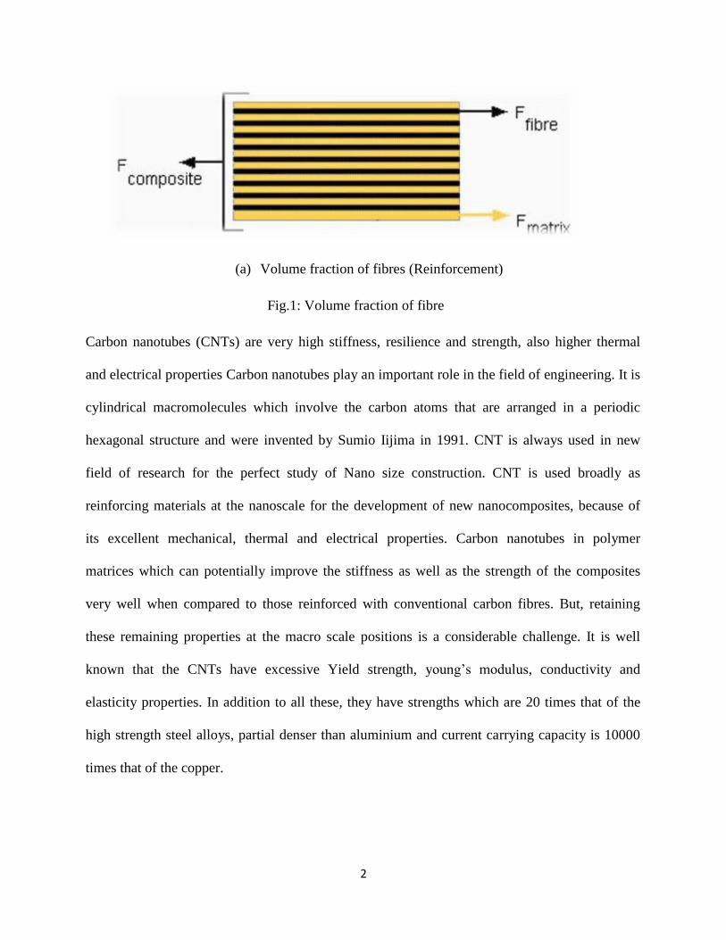
(a) Volume fraction of fibres (Reinforcement)
Fig.1: Volume fraction of fibre
Carbon nanotubes (CNTs) are very high stiffness, resilience and strength, also higher thermal
and electrical properties Carbon nanotubes play an important role in the field of engineering. It is
cylindrical macromolecules which involve the carbon atoms that are arranged in a periodic
hexagonal structure and were invented by Sumio Iijima in 1991. CNT is always used in new
field of research for the perfect study of Nano size construction. CNT is used broadly as
reinforcing materials at the nanoscale for the development of new nanocomposites, because of
its excellent mechanical, thermal and electrical properties. Carbon nanotubes in polymer
matrices which can potentially improve the stiffness as well as the strength of the composites
very well when compared to those reinforced with conventional carbon fibres. But, retaining
these remaining properties at the macro scale positions is a considerable challenge. It is well
known that the CNTs have excessive Yield strength, young’s modulus, conductivity and
elasticity properties. In addition to all these, they have strengths which are 20 times that of the
high strength steel alloys, partial denser than aluminium and current carrying capacity is 10000
times that of the copper.

3
1.2 Types of CNTs
CNTs can be characterized by their structures (a) single walled carbon nanotube (SWNT) (b)
multi walled carbon nanotube (MWNT) and (c) double walled carbon nanotube (DWNT). Single
walled carbon nanotube is nanometre-diameter tube made up of a single rolled up graphene sheet
to form a cylinder and MWNT consisting of multiple rolled up graphene area to form a cylinder
but diameter of MWCT is greater than diameter of SWNT is represented in Fig. 2:
(a) A cut- out part of a graphene sheet (b) A single walled CNT (C) A multi walled CNT

4
(d) Graphene sheets rolled into SWCNT
Fig.2: Types of CNTS [36]
1.3 CNTs geometry
CNTs have three exceptional geometrical preparations of carbon atoms. These CNTs can be
categorized by how graphene sheet is wrapped into a tube form. Because of physical and
mechanical properties of CNTs are depending on its atomic arrangement. There are three types
of carbon atom (a) armchair, (b) chiral, and (c) zig-zag as shown in Fig. 3

5
(a) Arrangement of carbon atom for armchair (b) Arrangement of carbon atom for zig-zag
(a) Arrangement of carbon atoms for chiral
Fig.3:Arrangement of CNTS for armchair,zig-zag and chiral [37]

6
1.4 Applications of CNTs
CNTs are applied to chemical, mechanical, thermal, electronic and optical field. Carbon
nanotube is likely to revolutionize in changed fields such a nanotechnology and material science.
CNTs have wide selection of unfamiliar potential applications in many technological fields such
as automobile, aerospace, medicine, energy, and chemical industry, in which CNTs may be used
as models, gas absorbents, composite fibres material, actuators, substance supports, chemical
sensors, probes, nano reactors, nano pipes etc. The key of using CNTs based on FGM is that one
can obtain these properties as per the requirement just by varying the distribution and
composition of CNTs. That’s how one can get directional properties and can control other
parameters. Another advantage stated above is the stress concentration free material because the
cross-section shows there are no layers inside the material and instead there is a continuous
gradation of materials from top to bottom. So, there is no stress concentration and delamination
of layers.
1.5 Motivation of the Present Work
The carbon nanotubes CNTs based on composite plate provides highly motivation to the science
and technology because of its excellent mechanical, physical, electrical and thermal properties.
CNTs are providing effective size, shape, structure, strength to mass ratio, stiffness to mass ratio,
wear resistance good elevated temperature properties and the composites based upon CNTs
having capability to manufacture guiding mechanical properties and providing capability to
mechanism the deformation, forceful reaction of the classification, wear and corrosion of shares
etc. In the modern few years, use of composite structures has improved a lot, especially in

7
aerospace/ aeronautical engineering. The researchers now give their effort on CNTs due to above
reason. These structural components are subjected to many types of shared loading and visible to
elevated thermal environment during their feature, which may lead to change in the shape of the
geometry of arrangement. The changes in panel geometry and the interface with loading
condition affect the bending responses significantly. The important aim of this present work is to
increase fastening load and control the variability of a structure.
1.6 Aim and Scope of the Present Thesis
The main aim of the thesis are to develop a mathematical model for uniformly distributed single
walled carbon nanotubes based on composite plate under various loads and environment
temperature using the parametric language in ANSYS 15.0 environment and then calculate its
bending responses and free vibration subjected to compressive and tensile load alternately on its
adjacent boundaries, based on finite element method. A suitable finite element classical is
projected and applied for the discretisation of the composite plate model. It also aims to obtain
the effect of uniformly distributed CNT composite plate and other geometrical parameters such
as CNT volume fraction, thickness ratio; environment temperature, boundary conditions,
compression and tension on the bending responses of the CNTs based composite plate.

8
CHAPTER 2
LITERATURE REVIEW
Numerous investigated studies and simulations have been performed to study the material
properties of the CNT reinforced composites plate. A carbon nanotube is estimated of having
young’s modulus in the array of tera Pascal (TPA) coupled with high stiffness. Because of these
exceptional properties SWCNTs are being widely used in aerospace and biomedical field .The
elastics material properties of single walled CNTs and multi-layered carbon nanotubes have been
calculated by empirical models.
Zhu et al. [1] computed the free vibration and bending behaviour of the functionally graded
carbon nanotube reinforced composite plates (FG-CNTRC) according to the first order shear
deformation theory (FSDT) of plate and determines effective physical properties of the
nanocomposite plates using extended rule of mixture. Complete parametric studies of the volume
fractions of carbon nanotubes and the ratios of width-to-thickness on the bending responses, and
fundamental frequencies of the plates and surroundings temperature. Han and Elliott [2]
presented the standard molecular dynamics (MD) simulations method to examine the material
properties of polymer/fiber composites. Polymer matrices: poly (methyl methacrylate) (PMMA)
and poly{(m-phenylenevinylene)- co-[(2,5-dioctoxy-p-phenylene) vinylene]} (PmPV) are used
as matrix. Jin and Yuan [3] studied effective elastic modulus of single-walled carbon nanotubes
using molecular dynamics (MD) simulations. There are two methods available to evaluate the
material properties of CNTs force and energy method. Kumar and Srinivas [4] evaluated the
effective material properties of CNTs reinforced polymer by representative volume element
method using ANSYS. Rossi and Meo [5] studied the mechanical properties of SWCNT are

9
recently considered both theoretically and experimentally process. Evaluate mechanical
properties as elastic modulus, strain and ultimate strength by finite element method. Alibeigloo
and Liew [6] employed three-dimensional theory of resistance, bending behaviour of (FG-
CNTRC) rectangular plate exposed to thermo-mechanical loads. Ansari [7] examined the
buckling performance of the silicon carbide nanotubes material Molecular mechanism are
genrally related to the density functional theory. Murmu and Pradhan [8] observed the buckling
behaviours of SWCNTs surrounded in flexible medium using Timoshenko beam theory and
Eringen’s nonlocal elasticity. Shen [9] computed the nonlinear bending analysis of functionally
graded composites plates reinforced by SWCNTs by using the higher order shear deformation
plate theory (HSDT) through a Von-Karman based nonlinearity. Popov et al. [10] estimated the
elastic properties of triangular close-filled crystal matrices of SWCNTs using analytical words
based on a force-constant lattice dynamical model. Ayatollahi at el. [11] estimated the nonlinear
mechanical properties of the zigzag and armchair SWNTs bending, under axial and torsional
loading conditions using FEM and molecular mechanics. Odegard et al. [12] evaluated a
constitutive classical for polymer composite structures reinforced with SWCNTs. Chen and Liu
[13] estimated the real mechanical properties of CNTs based on composites using a square
representative volume element (RVE) based on the continuum mechanism and with the finite
element model (FEM). Shen and Xiang [14] investigated the post buckling of SWCNTs
reinforced nanocomposite cylindrical shells under thermo-mechanical loading. The model has
been developed based on HSDT panel theories with a von Karman type it is not linearity
kinematics. Thai [15] employed a nonlocal tangential deformation beam theory to study the
vibration buckling, and the bending. Guo et al. [16] employed an atomic measure finite element
model (FEM) to analyse buckling and bending performance of carbon nanotubes (SWCNTs).

10
Zhang et al. [17] calculated the thermal buckling reactions of carbon nanotubes CNTs using
finite element model (FEM). Mohammadimehr et al. [18] investigated the buckling performance
of double-walled carbon nanotubes surrounded in an elastic standard under axial compression
expending non-local elasticity theory. Sears et al. [19] studied buckling of MWNTs and SWNTs,
correspondingly under the axial compressive forces have been studied by MDs, and outcomes
compared with those from the investigation of equivalent range assembly using finite element
method and Euler buckling theory based upon molecular measure (e.g molecular dynamic forces,
montecarlo) and small measure. Vodenitcharova et al. [20] investigated bending and buckling
analysis of nanocomposite beam reinforced by SWCNTs, analysed the matrix deformation using
Airy stress function. Also, it has been found that adding a quantity of CNTs reinforced in matrix
increased load carrying capacity of the structure. Sun and Liew [21] studied a bending buckling
behaviour test of SWCNTs using advanced order gradient scale and mesh free technique. Yan et
al. [22] investigated the buckling test higher-order Cauchy–Born rule and numerical simulation.
Giannopoulos et al. [23] studied the elastic modulus and tangential modulus of the atomistic
microstructure of the nanotubes by bond extending, bond angle bending and torsional spin
resistance load constants. Lei et al. [24] presented free vibration analysis of FG material
nanocomposite panels reinforced by (SWCNTs), using the component-free kp-Ritz method.
Aydogdu [25] presented nonlocal beam model free vibration, buckling and bending of
nanobeams using the structural and forceful analyses of single-walled carbon nanotubes
(SWCNTs). Simsek [26] presented dynamic vibration of a simply reinforced single-walled
carbon nanotube (SWCNTs) exposed to a moving simple harmonic load using nonlocal Euler–
Bernoulli beam model The effects of nonlocal parameter, the excitation frequency, velocity and
aspect ratio. Fiedler et al. [27] presented the potential energy of the CNTs (fibre) in polymers,

11
the relation among particle volume, separation and size content is described systematically. The
subsequent (fracture) mechanical properties of the CNT/epoxy composites material (DWCNT-
NH2) is analysed by transmission electron microscopy (TEM). Lu and Hu [28] adopted
Computational model for calculating mechanical properties of single-walled carbon nanotubes
(SWCNTs) as it is an influential tool relative to the tentative difficulty. and investigated the
things of diameters of helicity on young’s modulus and the tangential modulus of SWCNTs. Yu
et al. [29] studied the carbon nanotubes (CNTs) and the fibre and polymer matrix boundary
coating the chemical vapour deposition (CVD) method using methyltrichlorosilane (MTS).
Properties of the CNTs on mechanical and thermal effects of the composite material calculate by
three-point flexible test, single-edge notched beam (SENB) test. Formica et al. [30] employed the
vibrational effects of carbon nanotubes the Eshelby–Mori–Tanaka the single-walled carbon
nanotubes (SWCNTs).The composite panel are made of a purely isotropic elastic material
introducing matrix of three dissimilar types (concrete, rubber, and epoxy ). Odegard et al. [31]
developed the assembly-property relations of Nano-structured resources. This technique attends
as a link between computational solid mechanics and chemistry by replacing separate molecular
arrangements with equivalent-field models. Calculate the effective-field geometry and bending
inelasticity of a graphene sheet subjected to cylindrical bending. Volcov et al. [32] studied the
bending buckling analysis of single-walled carbon nanotubes (SWCNTs) based on thermal
conductivity of CNTs. microscopic simulations and atomistic. Nonequilibrium it is used in
molecular dynamics (MD) simulations of the thermal conductance through a separate buckling
kink in a (10, 10) armchair shape CNT. Ma et al. [33] investigated the surface, diffusion and
interfacial properties of carbon nanotubes (CNTs), the functionalization efficiently constrain the
re-agglomeration of CNTs through the remedial of resin. These finalising properties along with

12
enhanced interfacial linkage between the matrix and reinforced CNTs. Liu and Chen. [34]
Presented the progresses in the boundary element technique for carbon nanotube (CNTs) based
on composites and finite element method to demonstrate the efficiency of BEM. Coleman et al.
[35] presented a review paper to evaluate the mechanical properties of carbon nanotube–polymer
composites.
Based on the above literature, it is clear that many attempts have been made to study the
mechanical free vibration and bending behaviour of FG-CNTRC but the studies with temperature
dependent material properties were very rare. Hence, the present research work focus on the
analysis of the mechanical free vibration and bending analysis of uniformly distributed (UD) and
FG-CNTRC with temperature dependent material properties. A simulation model is developed
using ANSYS parametric design language (APDL) in ANSYS environment.

13
CHAPTER 3
GENERAL MATHEMATICAL FORMULATION
3.1 Molecular Dynamics Simulation
The modelling of mechanical properties of Nano composites is done by the help of
molecular dynamics simulation (MDs) by using direct methods, and the other method used is
finite element simulation technique by “continuum” methods. Molecular dynamics is the utmost
in depth molecular simulation method that computes the motion of distinct molecules. Coupled
Newton’s equation of motion, it defines the place and momentum, are explained for a huge
number of atoms in separated bunch or in the bluck by the use of periodic boundary conditions.
Molecular dynamics usually contains of three components.
(1) A traditional of the first conditions (e.g., the initial positions and also the velocities of all
atoms in the system)
(2) The interface potential energy to characterise the all the forces among all the atoms.
(3) The development of scheme in the time by statistically explaining a set of classical
Newtonian equations of the motion for totally atoms in the system. In the year 1997, Cornwell et
al. used the molecular dynamics to calculate the elastic properties of single-walled carbon
nanotubes SWCNTs. In current areas, molecular dynamics simulation have been broadly used in
expecting materials properties of CNTs and nanotubes reinforced composites material ,
graphite/epoxy nanocomposites, and the other nanocomposites. Molecular dynamics simulation
contains a suitable selection of the interaction potential energy of particles, geometric
combination, periodic edge conditions, and this is the controls of temperature and pressure for
14
simulator materially meaningful thermodynamic groups. The relations potentials energy together
with their constraints forms a force field that explains in detail how the particles in a system
interact with each other particles. Such a dynamic ground can be attained by the quantum system
and empirical method or quantum-empirical method. The standards used for choosing a dynamic
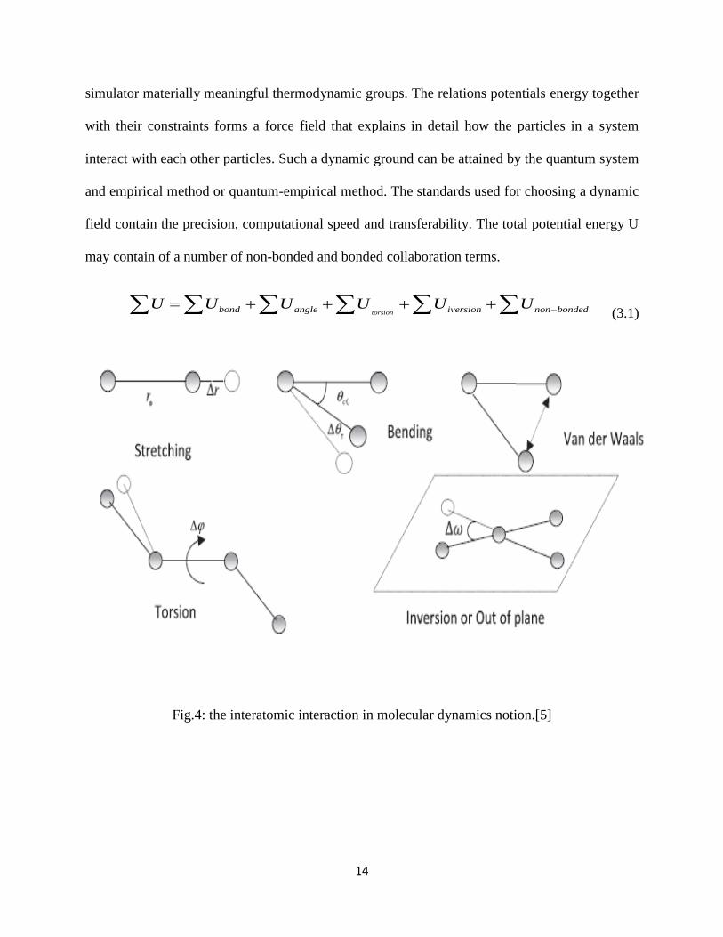
field contain the precision, computational speed and transferability. The total potential energy U
may contain of a number of non-bonded and bonded collaboration terms.
torsionbond angle iversion non bondedU U U U U U (3.1)
Fig.4: the interatomic interaction in molecular dynamics notion.[5]

15
Fig.5: boundary loading conditions for SWCNT armchair (10,10) [11]
3.1.1 Structure of carbon nanotube
Single-walled nanotubes SWCNTs are designed by folding a graphene sheet to
procedure a hollow tube that is collected of the hexagonal shape carbon circle units, they are
usually referred as graphene units. The important carbon nanotube structure which can be
categorised into three types: (1) Armchair of atoms (2) zigzag of atoms and (3) chiral of atoms
in relations of their helicity. Fig. [6] Shows a part of a single graphite plane it can be converted
into a carbon nanotube by rolling a tube. To designate this construction, a chiral direction is
given by the equation OA=na1+ma2, where a1 and a2 are unit directions for the graphene sheet,
there are two integers of n and m, along with a chiral angle θ that is the angle of the chiral
direction with respect to the x co –ordinate shown in Fig.[6] The chiral direction, OA will be
represented by (n, m) which will also identify the structure of the CNT. The direction OB is
perpendicular to the direction OA. To geometry a CNT, we cut off the squares OABO and roll it
16
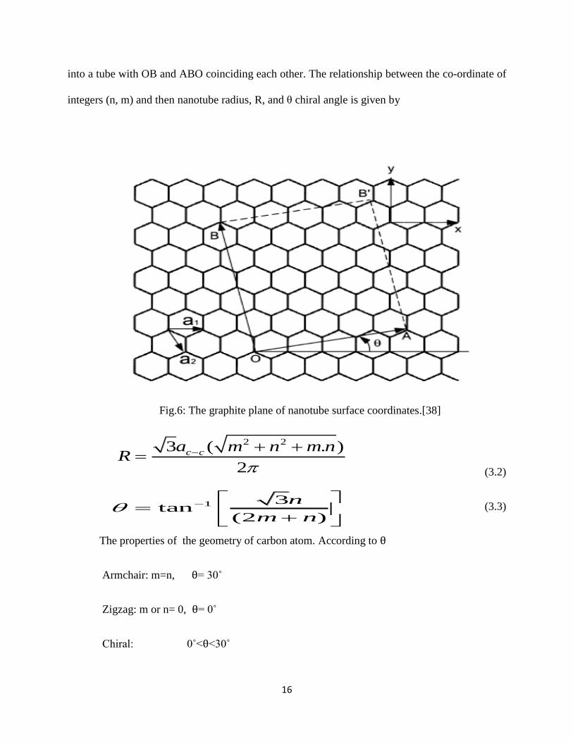
into a tube with OB and ABO coinciding each other. The relationship between the co-ordinate of
integers (n, m) and then nanotube radius, R, and θ chiral angle is given by
Fig.6: The graphite plane of nanotube surface coordinates.[38]
2 23 ( . )
2
c ca m n m nR
(3.2)
(3.3)
The properties of the geometry of carbon atom. According to θ
Armchair: m=n, θ= 30˚
Zigzag: m or n= 0, θ= 0˚
Chiral: 0˚<θ<30˚
1 3tan
(2 )
n
m n

17
3.2.2. Force fields and total potential energy
The molecular dynamics MD simulation methods are deterministic which is based on the
Newton’s second law of motion, F ma here F is the force applied on an atom, m is the mass
of atoms and a is its acceleration of atoms. From information of the force on each atom, the
acceleration of the each atom in the structure can be evaluated. The mathematical addition of the
equations of motion produces a path that terms the positions, velocities and accelerations of each
atom with respect to time. From this path, the mean values of properties can be calculated. The
atomic relationship is explained by force potentials connected with Bonding and nonbonding
phenomena. The relation potential energy is the sum of bonding energy and non-bonding energy.
bonded non bondedU U U (3.4)
For carbon nanotubes, this nonbonding duration is mostly the energy of van-der-Waals force, the
normally have a weak inspiration on the totally mechanical behaviour between the atomic
connections of the carbon microstructure. The van-der-Waals force is most regularly modelled
using the Lennard–Jones 6-12 potential function.
12 6
ij ij
vander waals
nonbondedpair ij ij
A CP
r r
(3.5)
Where A and C are the atom-type reliant on constants. ij ij i jr r r r | is the distance between
two molecules, i and j, and ri and jr are the position directions of
thi and thj atom. The main
part of the overall potential energy, the bonding energy, is a sum of three changed connections
among atoms: bond stretching, bond bending, and bond torsion. Two potential energy are
negligible.

18
bonded bond stretch angle bend torsionU U U U (3.6)
Where U is generally used potential energy functions are given by the equation
2
01,2
bond stretch s ijpairs
U K r r (3.7)
2
0angle bendangles
U K (3.8)
0
1,4
1 costorsion
pairs
U K n (3.9)
Where r0 is equilibrium distance of bond. There are three type of this bond, sK is the
spring force of bond, K is the force of bending, and Kis the torsion force, this is the ideal part
for this bond type, and where n is periodicity of the bond. The constants are firm as
approximations for the complete quantum relations of the electron wave roles fundamental the
interaction of unlike carbon atoms. A statistical program is generated to evaluate the mutual
relations forces determined by the slope of the overall potential energy of a single-walled
nanotube, F= -∇U Applying Newton’s Second Law of motion, the Verlet technique is used for
carrying out the addition at definite time steps to get atom path.
There are two methods to evaluate the elastic properties of carbon nanotubes.
(1) Force method (2) Energy method

19
(1) Force method:
The elastic properties of CNTs are recorded by direct computation of the mean dynamic
developed between the carbon atoms in the nanotube. Virial theorem, a force method is used for
calculation of the effective elastic modulus in longitudinal direction. This equation is given by
0
1
2ij ijF r
V
(3.10)
Where is the average atomic level stress tensor in the Cartesian Coordinates,
ijF is
interatomic forces with bonding and nonbonding forces between two molecules i and j, ijr is the
distance between two atoms and V0 is the initial volume of the carbon nanotube, this is a hollow
cylinder. V0= 2πhLr where h is the assumed thickness of hollow cylinder, L is length of tube
wall and r is radius of tube wall.
(1) Energy method:
The second derivative of the potential energy with respect to the strain under each bend
approach is utilized for calculation of elastic modulus.
2
0
1ijkl
ij kl
UC
V
(3.11)
Where ijklC is the fourth-order tensor of elastic constants and
ij is the strain tensor. and U is
potential energy.
The potential energy is used in energy method under small strain deformation equation is given
by 0 0
1
2ijkl ij klU U V C
(3.12)

20
Where U is the overall potential energy at the equilibrium and U0 is initial potential energy at the
equilibrium before bend is applied.
The common elastic features of carbon nanotubes will now be discussed. Due to the hexagonal
symmetry properties in the tube surface of nanotube, the nanotube transverse isotropy in the θ–z
plane, this is independent of five elastic constants in the stress and strain relationships.
11 13 13
13 33 23
13 23 33
rr rr
zz zz
C C C
C C C
C C C
(3.13)
, ,z Z Z rz rz rz r r rG G G (3.14)
Where 2 1
zz
z
EG
The equation is expressed in terms of engineering constants as
1
1
1
zr zr
r z z
rr rr
zzr
z z z
zz zz
zzr
z z z
v v
E E E
vv
E E E
vv
E E E
(3.15)
(1) Evaluation of elastic modulus E1 and Poisson vzθ
The axial young’s modulus EZ and the Poisson ratios, vz the atoms are displaced by
0
zz zzu z the average strain and stresses are: 0
zz zz
0zz , any other 0ij

21
The MD simulation, the longitudinal elastic modulus, EZ, can be evaluated by force and
energy method.
(a) Force method 0
ZZZ
ZZ
E
(3.16)
(b) Energy method 2
0 2
0
1Z
ZZ
UE
V
(3.17)
(c) Poisson’s ratio is obtained as: 0z
zz
v
(3.18)
(2) Calculation of E2 and v𝜃z
The radial displacement 0
ru r is applied to every atom of carbon nanotube then we
are obtain only a hoop stress 0
0 , any other 0ij
The MD simulation, the transverse elastic modulus, Eθ
(a) Force method 0E
(3.19)
(b) Energy method 2
0 2
0
1 UE
V
(3.20)
(c) Poisson’s ratio is obtained as: 0
zzzv
(3.21)
(3) Calculation of the rotational shear modulus G𝜃Z and the displacement mode 0
zu
0
z z , any other 0ij
0z , any other 0ij

22
(a) Force method 0
ZZ
Z
G
(3.22)
(b) Energy method 2
0 2
0
1Z
Z
UG
V
(3.23)
(4) Calculation C23 and C33
The carbon atoms are under deformation 0
z zzu z and lateral displacement are constrained
0
zz zz , any other 0ij
This is relationships stress and strain; C23 and C33 are given by
(a) Force method 23 0
zz
C
(3.24a)
33 0
zz
zz
C
(3.24b)
(b) Energy method 2
33 0 2
0
1
zz
UC
V
(3.25)
Where C13 can be evaluation using a force method, this elastic modulus is small value, the
determination of C13 is not attempted.
Fig (a) Solid CNT through MD

23
Fig (b) Hollow CNT through MD
Fig.7: Solid and Hollow CNTs through MD
3.2 Finite Element Method and ANSYS
Nowadays the advancement in the technology, the design engineering method is also close
to precision, as the finite element model (FEM) is used broadly and capable to drawing the
complicated structure and this method is very important tool for the designing process of any
shape and construction. It shows an important role in forecasting the responses of different
products, parts, assemblies and subassemblies. The FEM is very extensively used by all
advanced field in which save their huge time of prototyping with decreasing the cost due to
physical check and increases the revolution at a faster and more accurate path. There are various
optimized finite element analysis (FEM) tools are obtainable in this market and ANSYS
parametric is one of them (FEM) is acceptable to several industries and analysts.
Nowadays, ANSYS is creature used in different engineering areas such as power
generation, electronic devices, transportation, and household appliances as well as to analyse the

24
vehicle simulation and in aerospace industries. ANSYS gradually enters into the number of
fields which is making it convenient for the fatigue analysis, nuclear power plant and medical
applications. ANSYS is also very useful in structural analysis.
SHELL281 element description.
The shell element is using for bending analysis. The element has eight-node with six degrees
of freedom for each node. Shown in fig.8 is select from the element library of ANSYS 15. That
is translations in the nodal x, y and z directions.
Fig. 8: Shell 281element description.
xo = The x-axis of element co-ordination is not provided.
x = The x-axis if element co-ordination is provided.

25
A layout of procedure in ANSYS:
:
3.3 Carbon Nanotube Composites Plate
In this paper, UD- CNT composite plate using length a, width b and depth are measured.
UD-CNT composite plate represents the uniform supply the functionally graded spreading of
carbon nanotubes in the depth direction of the composite plates. The effective material properties
of the two-part Nano composites, it is the rule of mixture of CNTs and an isotropic polymer and
can be calculated according to the extended rule of mixture. Due to the relaxed and suitability,
in the work the rule of mixture was active by presenting CNT efficiency constraints and
effective material properties of the CNTRC plates is given by the equation.
GEOMETRY
ELEMENT TYPE
MATERIAL PROPERTIES
MESH DEFINATION
BOUNDARY CONDITION
ANALYSIS
POST PROCESSSING

26
11
CNT m
CNT mE E V E V (3.26)
2
22 22
CNT m
CNT m
V V
E E E
(3.27)
3
12
12
CNT m
CNT m
V V
G G G
(3.28)
Where,11
CNTE , 22
CNTE and 12
CNTG are the elastic constants of SWCNT andmE ,
mG are
characterize the elastic properties of the matrix. 1 ,
2 and 3 are the CNT effective parameters
and it can be estimated by the effective material properties of CNTRC based on the rule of
mixture and molecular dynamic (MD) simulation. CNTV And
mV are the volume fractions of the
fibre and volume fraction of matrix. 11E And
22E are the effective Young’s modulus of carbon
nanotubes reinforced composite plates in the main material coordinates,12G ,
13G and 23G are the
tangential modulus, 12v and
21v are Poisson’s ratios and 11 and
22 are thermal expansion
coefficients.
In the same way, the thermal extension coefficients, 11 and
22 individually, in this type
the longitudinal and transverse ways, Poisson’s ratio 12v and ρ the density of the Nano composite
plates find out in the same way as relation between the CNT and matrix volume fractions is
shown as.

27
1CNT mV V
(3.29a)
*
12 12
CNT m
CNT mv V v V v (3.29b)
CNT m
CNT mV V (3.29c)
11 11
CNT m
CNT mV V (3.30a)
22 12 22 12 11(1 ) (1 )CNT CNT m m
CNT mv V v V v (3.30b)
Here, CNTv and m are Poisson’s ratio of CNT and matrix, respectively and
11
CNT , 22
CNT and m
are the thermal expansion coefficients of the CNT and matrix.
Fig.9: Carbon nanotube reinforced composites plate. [1]

28
3.4 Free vibration of CNTC plate
The vibration which occurs when the mechanical system is set off with an initial input and then
permissible to vibrate freely. As for Examples this physical type of vibration are pulling of a
child back on the swing and then letting go. The mechanical system then vibrates at one or more
of its "natural frequency" and damp down to zero.
In a free vibration analysis, the CNT composite plate is assumed to undergo a harmonic motion
and the recorded eigenvalue and eigenvector equations are given by
(3.31)
Where K0 is the global stiffness matrix, M is the global mass matrix and ω is normal frequency
are calculated by assembling the element mass matrix eM
[ ] [ ]
e
e e T eM d
(3.32)
[ρ] =
0 1
0 1
0
1 2
1 2
0 0 0
0 0 0
0 0 0 0
0 0 0
0 0 0
J J
J J
J
J J
J J
(3.33)
Where 0 1,J J and
2J are the normal, coupled normal-rotary and rotary inertial coefficient
respectively.
2
2
0 1 2 1 1 1
2
( ) ( )(1, , )
h
h
J J J Z Z Z
(3.34)
2
0( ) 0K M d

29
The non-dimensional natural frequency equation is given by
2 m ma h E (3.35)
3.5 Bending Analysis of CNTC plate
Bending analysis is nothing but the geometrical shape change of structural component and
usually curve in nature. Numerous analyses have been reported in the literature on the bending
analysis by taking the geometric matrix and the stiffness matrices in von-Karman sense based in
various theories such as classical plate theory and the shear deformation theories. Lots of
literature are there on carbon nanotube of the composite plate due to bending loadings. A few of
them are discussed here.
The generalized displacements at any point within an element e are approached.
0
1
( , ) ( ) ( )m
h e e
i i
i
U X t X d t
(3.36)
Where e
i is the lagrangian interpolation functions and
ed is expressed as nodal displacements
of the elemente . The finite element equations of CNT composites plates subjected to a
uniformly distributed transverse load is given by
Kd F (3.37)
Where K is the global stiffness matrix and F is load vector these are computed by assembling.

30
CHAPTER 4
RESULT AND DISCUSSION
4.1 Evaluation of material properties of carbon nanotubes using MD
simulation
In MD simulation, this is used parameters of length, diameter and different temperature. We are
deciding of no of atoms and no of iteration.
Table.1: The comparison of material properties in molecular dynamics.
Temperature
(˚K)
Material properties Zhu et al. [1] Present (MD)
300 E1 5.6466 5.543
500 E1 5.5306 5.486
700 E1 5.4744 5.368
4.2 Effect of volume fraction on the non-dimensional elastic modulus of CNT
CNT geometry is generally influenced by the chiral vector (n, m), the conclusion of chirality on
elastic modulus as estimated by Halpin–Tsai method [35]. It is realized that zigzag CNT with
chiral vector (10, 0) gives higher non-dimensional elastic modulus. Various numerical examples
are discussed in this section and they are validated with reference. Fig.10 shows the effect of
volume fraction on the non-dimensional elastic modulus. In MD simulation, young’s modulus
(EZ =1208GPa) and polymer matrix (Em =2.5) are used.

31
Table.2: Comparison of non-dimensional elastic modulus (Ez/Em ) for different volume fraction.
Volume Kumar and
Srinivas [4]
Present
(MD)
Kumar and
Srinivas [4]
Present
(MD)
Kumar and
Srinivas [4]
Present
(MD)
Fraction (%) CNT (10,0) CNT(10,0) CNT(10,5) CNT(10.5) CNT(10,10) CNT(10,10)
1 2.06 2.23 1.993 2.01 1.75 1.75
2 3.31 3.61 2.77 3.07 2.34 2.52
3 4.48 4.95 3.67 4.00 3.01 3.29
4 5.64 6.33 4.66 5.04 3.64 4.09
5 6.73 7.73 5.56 6.02 4.31 4.97
1 2 3 4 51
2
3
4
5
6
7
8
No
n-d
ime
nsio
na
l e
lastic m
od
ulu
s
(Ez/E
m)
Volume fraction (%)
(10,0) [4]
(10,0) MD [Present]
(10,5) [4]
(10,5) MD [Present]
(10,10) [4]
(10,10) MD [Present]
Fig.10: Variation of non-dimensional elastic modulus of CNT composite plate for different
types of fibres.

32
Table.3: The material properties of (10, 10) SWCNT (L = 9.26 nm, R = 0.68 nm, h = 0.067 nm.
12
cntv =0.175. [1]
Temperature
(°K)
E1
E2 G12 α11 (10-6 /°K) α22 (10-6 /°K)
300 5.6466 7.0800 1.9445 3.4584 5.1682
4.3 Numerical illustrations.
In present analysis the PmPV is used as the matrix and the material properties of PmPV are
vm =.34, ρm =1.15 g/cm3, and Em =2.1 GPa at room temperature (300K). SWCNTs are used as
fibre material for bending and free vibration analysis and the material properties are present
in table 3. The extended rule of mixture used to evaluate the material properties of CNTRC
plate. Effectiveness parameter of CNT1 = 0.149 and
2 =0.934, for CNTV =0.11,
1 =0.150
and 2 =0.941 for the case of
CNTV =0.14, and 1 =0.149 and
2 =1.381 forCNTV
=0.17. We
assume that G23=G13=G12 and3 2
. The width to thickness ratio (a/h=10, 20 and 50) and
volume fraction are taken as design parameter of bending analysis. The thickness is taken to
be 2.0mm. The uniformly distributed carbon nanotube composites square plate (a/b=1) is
considered with boundary conditions (a) SSSS, (b) CCCC and (c) SCSC. Uniformly
distributed load (q0= -0.1MPa) used to calculate the bending behaviour of the composite
plate.

33
4.3.1 Bending analysis
For bending analysis, non-dimensional central deflection is obtained using /W W h
formula. Figs.11-13 shows the non-dimensional central deflection of CNT composite plate
for different support condition under uniformly distributed load. From figures it is clearly
shown that the non-dimensional central deflection of composite plate increasing with
thickness ratio (a/h) and also shown that non-dimensional central deflection is increasing
with volume fraction. For better understand three table are present.
Table.4: The non-dimensional central deflection for different thickness ratio (a/h) validation
using volume fraction (SSSS).
a/h Zhu et al.[1]
(VCNT = 0.11)
Present Zhu et al.[1]
(VCNT = 0.14)
Present Zhu et al.[1]
(VCNT = 0.17)
Present
10 0.003739 0.00373 0.003306 0.003315 0.002394 0.003015
20 0.003628 0.03625 0.03001 0.0301 0.02548 0.0259
30 0.0167 0.161 0.1292 0.1295 0.104 0.1045
40 0.488 0.484 0.381 0.385 0.311 0.315
50 1.155 1.153 0.9175 0.9195 0.7515 0.7645

34
Fig.11: Effect of thickness ratio on non-dimensional central deflection.
Table.5: The non-dimensional central deflection for different thickness ratio (a/h).
(a) CCCC
a/h (VCNT = 0.11) (VCNT = 0.14) (VCNT = 0.17)
10 2.2200E-03 2.0950E-03 1.9850E-03
20 1.3350E-02 1.1900E-02 1.0900E-02
30 4.5250E-02 3.8400E-02 2.9150E-02
40 1.1800E-01 9.2500E-02 7.6500E-02
50 2.6050E-01 2.1350E-01 1.8250E-01
10 20 30 40 50
0.0
0.2
0.4
0.6
0.8
1.0
1.2
No
n-d
imen
sio
nal
cen
tral
defl
ecti
on
Thickness ratio (a/h)
Volume fraction of CNT
0.11 Zhu et al. [1]
0.11 Present
0.14 Zhu et al. [1]
0.14 Present
0.17 Zhu et al. [1]
0.17 Present

35
Fig.12: Effect of thickness ratio on non-dimensional central deflection
Table.6: The non-dimensional central deflection for different thickness ratio (a/h).
(b)SCSC
a/h (VCNT =0.11) (VCNT =0.14) (VCNT =0.17)
10 3.32E-03 2.98E-03 2.74E-03
20 3.39E-02 2.86E-02 2.49E-02
30 1.53E-01 1.45E-01 9.85E-02
40 4.60E-01 3.73E-01 2.98E-01
50 1.10E+00 8.91E-01 7.50E-01
10 20 30 40 50
0.00
0.05
0.10
0.15
0.20
0.25
0.30
Volume fraction of CNT
0.11
0.14
0.17
Non-d
imensio
nal centr
al deflection
Thickness ratio (a/h)

36
Fig.13: Effect of thickness ratio on non-dimensional central deflection.
4.3.2 Free vibration analysis.
In free vibration analysis, the non-dimensional fundamental frequency is obtained using
2 m ma h E .Where ω is the natural frequency. The non-dimensional natural
frequency of CNT composites square plates are subjected to same influence from thickness
ratio and the volume fraction of CNT. Figs. 14-16 shows the effect of non-dimensional
fundamental frequency of composite plate increasing with thickness ratio (a/h) and also
increasing with the CNT volume fraction for different support condition (SSSS, CCCC and
SCSC).
10 20 30 40 50
0.0
0.2
0.4
0.6
0.8
1.0
1.2
No
n-d
ime
nsio
na
l ce
ntr
al d
efle
ctio
n
Thickness ratio (a/h)
Volume fraction of CNT
0.11
0.14
0.17

37
Table.7: The non-dimensional fundamental frequency for different thickness ratio (a/h)
validation (SSSS).
a/h Zhu et al.[1]
(VCNT= 0.11)
Present Zhu et al.[1]
(VCNT =0.14)
Present Zhu et al.[1]
(VCNT = 0.17)
Present
10 13.532 13.52938 14.306 14.31735 16.815 16.80776
20 17.352 17.33785 18.921 18.9309 21.456 21.43006
30 18.512 18.49868 20.415 20.43362 22.841 22.8248
40 18.973 18.96625 21.05 21.05459 22.402 22.385
50 19.223 19.19585 21.354 21.36252 23.697 23.6575
10 20 30 40 5013
14
15
16
17
18
19
20
21
22
23
24
No
n-d
ime
nsi
on
al n
atu
ral f
req
ue
ncy
Thickness ratio (a/h)
Volume fraction of CNT
0.11
0.11
0.14
0.14
0.17
0.17
Fig.14: The effect of thickness ratio on non-dimensional fundamental frequency.

38
Table.8: The non-dimensional fundamental frequency for different thickness ratio (a/h).
(a) CCCC.
a/h (VCNT = 0.11) (VCNT =0.14) (VCNT =0.17)
10 17.63852 18.14926 22.02397
20 28.39914 29.93935 35.30868
30 34.44871 37.05178 42.68662
40 37.76281 41.15209 46.6952
50 39.6704 43.5893 48.9897
Fig.15: The effect of thickness ratio on non-dimensional fundamental frequency.
10 20 30 40 50
15
20
25
30
35
40
45
50
No
n-d
imensi
on
al
fun
dam
enta
l fr
eq
uen
cy
Thickness ratio (a/h)
Volume fraction of CNT
0.11
0.14
0.17

39
Table.9: The non-dimensional fundamental frequency for different thickness ratio (a/h).
(a) SCSC
a/h (VCNT =0.11) (VCNT =0.14) (VCNT =0.17)
10 14.60667 15.37324 18.16507
20 18.34593 19.88725 22.70606
30 19.4875 21.36131 24.07742
40 19.94716 21.9715 24.62844
50 20.17313 22.27352 24.8972
Fig.16: The effect of thickness ratio on non-dimensional fundamental frequency.
10 20 30 40 50
14
15
16
17
18
19
20
21
22
23
24
25
Volume fraction of CNT
0.11
0.14
0.17
Non
-dim
ensi
on
al f
un
dam
enta
l fr
equ
ency
Thickness ratio (a/h)

40
CHAPTER 5
CONCLUSION
Free vibration and bending behaviour of uniformly distributed carbon nanotube composite
plate is analysed. The material properties of single-walled carbon nanotube evaluated
through molecular dynamics simulation using LAMMPS software. The effective material
properties of the composite plates are obtained using an extended rule of mixture. A finite
element model is developed for the single-walled carbon nanotube composite plate using
ANSYS Parametric Design Language (APDL) code in ANSYS environment. For the
discretization purpose, an eight-noded serendipity shell element is used from the ANSYS
library. Subsequently, the validation study is performed through the available published
literature. Finally, the parametric study is demonstrated by varying different material and
geometrical parameters for free vibration and bending responses of composite plate. The
present idea is validated through the judgment with those available in the literature paper.
Some new analytical investigation for different volume fractions, boundary conditions, and
temperature are explained. Based on the present study over the free vibration and bending
analysis performance of SWCNT composite plate, some arguments are concluded.
Based on the above statistical analysis the following conclusions are made:
The non-dimensional elastic modulus longitudinal parameter with increase in CNT
volume fractions.
Free vibration is observed that the non-dimensional fundamental frequency is
increasing with the volume fraction of CNT and also increasing the thickness ratio.
The non-dimensional central deflections are increasing with the thickness ratios and
the volume fractions.

41
Future Scope of the Research
Bending analysis of functionally graded carbon nanotubes composites plates can be
performed.
Free vibration of functionally graded multi-walled carbon nanotubes composites
(MWCNT) plates can be performed.
The effective material properties of CNT based on composite material will be
estimated through different material technique such as represented volume element
(RVE), Mori-Tanaka approach etc.
.

42
REFERENCES
[1] Zhu, P., Lei, Z. X. and Liew, K. M. ( 2012), “Static and free vibration analyses of carbon
nanotube-reinforced composite plates using finite element method with first order shear
deformation plate theory” composite structure, vol. 94, pp. 1450-1460.
[2] Han, Y. and Elliott, J. (2007), “Molecular dynamics simulations of the elastic properties of
polymer/carbon nanotube composites” comput. Materials sci., vol. 39, pp. 315-323.
[3] Jin, Y. and Yuan, F.G. (2003), “Simulation of elastic properties of single-walled carbon
nanotubes” Comput. Material sci., vol. 63, pp. 1507–1515.
[4] Kumar, P. and Srinivas, J. (2014), “Numerical evaluation of effective elastic properties of
CNT-reinforced polymers for interphase effects” Comput. Materials sci., vol. 88, pp.139-144.
[5] Rossi, M. and Meo, M. (2009), “Estimation of mechanical properties of single-walled carbon
nanotubes by using a molecular-mechanics based FE approach,” composites sci. and tech., vol.
69, pp. 1394-1398.
[6] Alibeigloo, A. and Liew, K. M. (2013), “Thermoelastic analysis of functionally graded
carbon nanotube-reinforced composite plate using theory of elasticity” composite structure, vol.
106, pp. 873-881.
[7] Ansari, R., Rouhi, S. Aryayi, M. and Mirnezhad, M. (2012), “On the buckling behaviour of
single-walled silicon carbide nanotubes” scientia iranica, vol. 19, pp. 1984-1990.
[8] Murmu, T. and Pradhan, S. C. (2009), “Buckling analysis of a single-walled carbon
nanotube embedded in an elastic medium based on nonlocal elasticity and Timoshenko beam
theory and using DQM” Physica, E., vol. 41, pp. 1232-1239.
[9] Shen, H. S. ( 2009), “Nonlinear bending of functionally graded carbon nanotube-reinforced
composite plates in thermal environments” composite structure, vol. 91, pp. 9-19.
[10] Popov, V. N., Doren, V. E. V. and Balkanski, M. (2000), “Elastic properties or critical of
single-walled carbon nanotubes” solid state communications, vol. 114, pp. 395-399.

43
[11] Ayatollahi, M. R., Shadlou, S. and Shokrieh M. M. (2011), “Multiscale modelling for
mechanical properties of carbon nanotube reinforced nanocomposites subjected to different type
of loading” composite structure, vol. 93, pp. 2250-2259.
[12] Odegard, G. M., Gates, T. S., Wise, K. E., Park, C. and Siochi, E. J. (2003), “constitutive
modelling of nanotube-reinforced polymer composites” composite sci. and tech., vol. 63, pp.
1671-1687.
[13] Shen, H. S. and Xiang, Y. (2013), “Postbuckling of nanotube-reinforced composite
cylindrical shells under combined axial and radial mechanical loads in thermal environment”
composite part B, vol. 52, pp. 311-322.
[14] Thai, H. T. (2012), “A nonlocal beam theory for bending buckling and vibration of
nanobeams” Inter. Journal of engg. Sci., vol.52, pp. 56-64.
[15] Chen, X. L., and Liu, Y. J. (2004), “Square representative volume element for evaluating
the effective material properties of carbon nanotube-based composites” computational material
science, vol. 29. PP. 1-11.
[16] Guo, X., Leung, A. Y. T., He, X.Q., Jiang, H. and Huang, Y. (2008), “Bending buckling of
single-walled carbon nanotubes by atomic-scale finite element” Composite part B, vol. 39, pp.
202-208.
[17] Zhang, D., Rangarajan, A. and Wass, A. M., “Compressive behaviour and buckling
response of carbon nanotubes” College of engineering, University of Michigan, Ann Arbor, Mi-
48109,USA.
[18] Mohammadimehr, M., Saldi, A. R., Arani, A. G., Arefmanesh, A. and Hal, Q. (2010),
“Buckling analysis of double-walled carbon nanotubes embedded in an elastic medium under
axial compression using non-local Timoshenko beam theory” Manuscrict.
[19] Sears, A. and Batra, R.C. (2006), “Buckling of multiwalled carbon nanotubes under axial
compression” Physical review B, vol. 73, pp. 085410-11.

44
[20] Vodenitcharova, T. and Zhang, L. C. (2006), “Bending and local buckling of a
nanocomposite beam reinforced by a single-walled carbon nanotube” Inter. National jour. of
solid and structure, vol. 43, pp. 3006-3024.
[21] Sun, Y. and Liew, K. M. (2008), “The buckling of single-walled carbon nanotubes upon
bending: The higher order gradient continuum and mesh-free method” Comput. Method Appi.
Mech. Engg., vol. 197, pp. 3001-3013.
[22] Yan, J. W., Liew, K. M. and He, L. H. (2012), “Analysis of single-walled carbon nanotubes
using the moving kriging interpolation” Comput. Method Appl. Mech. Engrg, vol. 229-232, pp.
56-67.
[23] Giannopoulos, G. I., Kakavas, P. A. and Anifantis, N. K. (2008), “Evaluation of the
effective mechanical properties of single walled carbon nanotubes using a spring based finite
element approach” Comput. materials sci., vol. 41, pp. 561-569.
[24] Lei, Z. X., Liew, K. M. and Yu, J. L. (2013), “Free vibration analysis of functionally graded
carbon nanotube-reinforced composite plates using the element-free kp-Ritz method in thermal
environment” Composite structure, vol. 106, pp. 128-138.
[25] Aydogdu, M. (2009), “A general nonlocal beam theory: Its application to nanobeam
bending, buckling and vibration” Physica E, vol. 41, pp. 1651-1655.
[26] Simsek, M. (2010), “Vibration analysis of a single-walled carbon nanotube under action of a
moving harmonic load based on nonlocal elasticity theory.
[27] Fiedler, B., Gojny, F. H., Wichmann, M. H. G., Nolte, M. C. M. and Schulte, K. (2006),
“Fundamental aspects of nano-reinforced composites” composites sci. and tech., vol. 66, pp.
3115-3125.

45
[28] Lu, X. and Hu, Z. (2012), “Mechanical property evaluation of single-walled carbon
nanotubes by finite element modelling” Composite: Part B, vol. 43, pp. 1902-1913.
[29] Yu, H., Zhou, X., Zhang, W., Peng, H., Zhang, C. and Sun, K. (2011), “Properties of carbon
nano-tubes-Cf/SiC composite by precursor infiltration and pyrolysis process” Material and
Design, vol. 32, pp. 3516-3520.
[30] Formica, G., Lacarbonara, W. and Alessi, R. (2010), “Vibration of carbon nanotube-
reinforced composites” Journal of sound and vibration” vol. 329, pp. 1875-1889.
[31] Volkov, A. N., Shiga, T., Nicholson, D., Shiomi, J. and Zhigilei, L. V. (2012), “Effect of
buckling of carbon nanotubes on thermal conductivity of carbon nanotube material” Journal of
applied physics, vol. 111, pp. 053501-11.
[32] Odegard, G. M., Gates, T. S., Nicholson, L. M. and Wise, K. E. (2002), “Equivalent-
Continuum modelling of nano-structured materials” Composite science and tech., vol. 62, pp.
1869-1880.
[33] Ma, P. C., Mo, S. Y., Tang, B. Z. and Kim, J. K. ( 2010), “Dispetsion, interfacial
interaction and re-agglomeration of functionalized carbon nanotubes in epoxy composites”
Carbon, vol. 48, pp. 1824-1834.
[34] Liu, Y. J. and Chen, X. L. (2003), “Evaluation of the effective material properties of carbon
nanotube-based composite using a nanoscale representative volume element” Mechanics of
materials, vol. 35, pp. 69-81.
[35] Coleman, J.N., Khan, U., Blau,W.J., K.Y. and Gunko. (2006), “A review of the mechanical
properties of carbon nanotube–polymer composites”, Comput material sci.,vol. 44, pp. 1624–
1652.

46
[36] Kreupl, F., Graham, A. P., Liebau, M., Duesberg, G. S., Seidel, R. and Unger, E., “Carbon
nanotubes for interconnect application” Infineon technologies AG, Corporate research, Otto-
Hahn-Ring 6, 81739 Munich, Germany.
[37] Grace, T. (2013) “An introduction to carbon nanotubes” Center on polymer interface and
macromolecular assemblies, pp. 1-14.
[38] Dresselhaus, MS. (1997), “Future directions in carbon science”, Annual Review of Material
Science, vol. 27, pp.1–34.
[39] Cornwell, CF. and Wille, LT. (1997), “Elastic properties of single-walled carbon nanotubes
in compression” Solid State Communications, vol. 101, pp.555–8.


![NERC this page%PDF-1.6 %âãÏÓ 7766 0 obj > endobj 7781 0 obj >/Filter/FlateDecode/ID[951F5A69D98AA94890BB9A97C64DA060>3A840F817421A049A37DF140A3FB73DB>]/Index[7766 32]/Info 7765](https://static.fdocuments.net/doc/165x107/5af201477f8b9abc788f2452/this-pagepdf-16-7766-0-obj-endobj-7781-0-obj-filterflatedecodeid951f5a69d98aa94890bb9a97c64da0603a840f817421a049a37df140a3fb73dbindex7766.jpg)


![Discovering Uniformly Accelerated Motion [11th-12th grades]](https://static.fdocuments.net/doc/165x107/61bea5814a30342b1a312ab8/discovering-uniformly-accelerated-motion-11th-12th-grades.jpg)