Free Flow-FF-System Manual - Techno-Solis
12
INSTALLATION OPERATION MAINTENANCE MANUAL Techno-Silis, Inc 301 20th Street South St. Petersburg, FL 33712 Phone: (727) 823-6766 Toll Free: (888) 99-SOLAR Fax: (727) 823-6768 Email: [email protected] Web: www.techno-Solis.com Free Flow-FF-System Manual
Transcript of Free Flow-FF-System Manual - Techno-Solis

INSTALLATION OPERATION MAINTENANCE MANUAL
Techno-Silis, Inc301 20th Street South
St. Petersburg, FL 33712
Phone: (727) 823-6766Toll Free: (888) 99-SOLAR
Fax: (727) 823-6768Email: [email protected]: www.techno-Solis.com
Free Flow-FF-System Manual

2
Contents:
OWNERS INFORMATION 3 What is a Thermosiphon System? 3 What is a Close Coupled System? 3 What is an Open Loop System? 3 What is a Closed Loop System? 3 How does my system work? 3 System Schematic Drawing 4 What system do I have? 4 Ancillary Energy Support (AES) System 5 How do I operate the system? 5 What should I do during holidays? 5 Why is there water discharge for the pressure valve? 5 What should I check before making a service call? 6
Low Solar Energy Input 6
Solar collector shading 6
AES System not operating 6
Is there excessive water discharge for the Valves? 6
Are you using more hot water than you think? 6
System Maintenance 6 Useful Technical Data 6 INSTALLATION INSTRUCTIONS 7 Location Selection 7 Typical Assembly Diagram 8 Connection and Mounting Kits 8 System Installation 8 Mounting Location 8 Mounting Systems Using Collector Model TS-26 8 Mounting Systems Using Collector Model TS-21 Plumbing Connections 11 ECTRICAL INSTALLATION INSTRUCTIONS 13 Electrical Connection for Electric AES Systems 13 Electrical Circuit Diagram 13 Electrical Connection for Gas AES Systems: 13 GAS (AES) INSTALLATION INSTRUCTIONS 13 Approved Gas Heater Models: 13 COMMISSIONING 14 Customer Hand Over 14 WARRANTY 15 5 Year Guarantee. 15 Scope of Warranty and Guarantee 15 INSTALLATION RECORD 16

3
Owners Information
As the owner of a TS DHW™ solar water heater there are some questions you may have about the system and how it operates. Your solar water heater model is commonly referred to as a roof mounted, open loop, close coupled, Thermosiphon system and is one of the most efficient solar water heater types available worldwide. What is a Thermosiphon System? A Thermosiphon system is a system where the heated water in the solar collectors rises up into the storage tank by natural Thermosiphon action. Thermosiphon action occurs when water which is heated in the collectors expands becoming lighter allowing colder heavier water to fall by gravitational force to the bottom of the collector. The cold water falling to the bottom of the collector pushes the hotter lighter water back up into the storage tank. This natural action commonly known as Thermosiphon action occurs without any moving parts or auxiliary electrical energy input to the system What is a Close Coupled System? A close coupled system is one where the household hot water storage tank and solar collectors are both mounted on the roof. Typically the tank is above but in close proximity to the collectors. The tank and collectors are connected together with ¾” copper tube, which is used to transfer heated water from the collectors to the storage tank. What is an Open Loop System? An Open Loop System is a system where the water used in the household (hot water) circulates through the solar collector panels transferring solar energy into the storage tank. This system type is used in locations where the ambient temperature never falls below freezing point (32°F) and where the water quality is good – less than 600 ppm Total Dissolved Solids (TDS). What is a Closed Loop System? A Closed Loop System is a system where two water loops are contained within the solar water heater. The first loop is the household water storage tank which stores the heated household water used within the household. The second loop is the solar collector loop which is fully sealed and mechanically separated from the household water loop by a heat exchanger system. The fluid within the solar collector loop is a mixture of household water and food grade propylene glycol. This fluid mix transfers solar energy from the solar collectors to the heat exchanger system and prevents damage to the solar collectors should the ambient temperature fall below freezing point. This system type can be used in any climatic location and with any water quality considered suitable for human consumption How does my system work? The three main components of your solar water heater system are the potable water storage tank, the solar collector (s) and Ancillary Energy Support (AES) System. The AES system can be either electric or gas operated dependant on the model purchased. The potable water storage tank is used to store the heated water ready for household use. It is constructed using high quality stainless steel to provide long life and is insulated with a high density polyurethane material to ensure minimal heat losses and maximized structural strength. The solar collectors contain a multi-tube copper water way system welded to a solar absorber plate, the combination of which collects solar energy and transfers it to the fluid within the collector loop. The absorber plate system is enclosed in an insulated metal casing covered with a high strength tempered glass sheet that protects the absorber system from physical damage. An electric Ancillary Energy Support (AES) system uses and electric element to heat part of the stored household water on those occasions when there is reduced solar energy available. (e.g. cloudy days). The electric element is thermostatically controlled so it only delivers the top up energy required then turns off automatically. A Gas AES system uses a remotely mounted gas continuous flow water heater connected in series with the hot water supply line to your house hot water pipe work. As the hot water from the solar storage tank passes through the gas heater its temperature is automatically monitored. If the temperature is below 120°F the gas heater will add the degrees required to deliver hot water of at least 120°F. If the water temperature is above 120°F the gas heater will not decide not to ignite. Under normal operating conditions the potable water within the storage tank is heated by the solar collectors. In an Open Loop System where the household hot water is in the collector loop, cold water is pushed downwards, via the long external pipe from the storage tank to the bottom of the solar collector. As the water is heated in the absorber by the sun, it rises to the top of the collector then travels through the short external pipe into the storage tank.

4
System Schematic Drawing
What system do I have? The model number of the system will provide this information. The model number is broken into sections to describe the system which you have installed. For example FF-80-42 The prefix letter(s) indicate the system type. e.g. FF-80-42 In the example, “FF” indicates that the system is a free flow (thermosiphon) type system. “D” would indicate a direct type system and “I” an indirect type system. The first numeric sequence indicates the storage volume of the solar storage tank. e.g. FF-80-42 In the example, 80 indicates a nominal tank volume of 80 gallons. The last numeric sequence indicates the total nominal collector area. e.g. FF-80-42 In the example, 42 is the area (ft²) of an two TS-21 (3’ x 7’) solar collectors. Ancillary Energy Support (AES) System Electricity and gas are the two options for the AES system. The most suitable AES system type used is made at the time of purchase from the TS DHW™ dealer. For electric AES systems the electricity supply electric element within the storage tank is automatically controlled by an internal thermostat which will only allow the electric element to operate if the storage tank water temperature falls below 120°F and will even then, only consume electricity until the water temperature is increased to 120°F then turns off again. For gas AES systems the electric element in the storage tank is not connected to an electricity supply. Instead a continuous flow gas water heater is fitted adjacent the storage tank and in series with the hot water supply from the storage tank and the household hot water pipe work system. As the hot water from the solar storage tank passes through the gas heater its temperature is automatically monitored by the gas heater. If the temperature is below 120°F the gas heater will add the additional degrees required to deliver hot water of at least 120°F. If the water temperature is above 120°F the gas heater will not decide not to ignite.

5
How do I operate the system? A TS DHW solar water heater is designed for fully automatic operation, so there is nothing you need to do for day to day system operation. If the AES System has been fitted with a remote isolator switch or time-clock, you may make the decision when and if Ancillary Energy Support is permitted. As a guide you may like to isolate the AES System during the summer months, you may use a time clock to permit boosting after sunset or any other combination, which suits your usage pattern. Careful use of these options can further reduce your energy needs for hot water supply to the household. Words of CAUTION All water heaters have the ability to produce hot water very quickly. To reduce the risk of scald injury it is recommended that a temperature control valve be fitted to the hot water supply pipe work. This valve should be checked at regular intervals to ensure its operation and settings remain correct. Please check that the pressure & temperature relief valve relief pipe is not located where it can cause damage if hot water is discharged. What should I do during holidays? If you are going to be away for a period of a week or more during the summer months it is advisable to turn off the electricity supply to the booster and if practical cover the solar collectors. If the solar collectors are not covered there is a possibility that the high temperature valve in the storage tank may open for a short period to reduce the storage tank temperature while you are away. This is a normal function and does not harm the system. Warning: If the hot water system is not used for two weeks or more, a quantity of hydrogen gas, which is highly flammable, may accumulate in the water heater. To dissipate this gas safely, it is recommended that a hot tap be turned on for several minutes at a sink, basin or bath but not a dishwasher, clothes washer, or other appliance. During this procedure there must be no smoking, open flame or any other electrical appliance operating nearby. If hydrogen is discharged through the tap, it will probably make an unusual noise as with air escaping. Do not place hands or any part of your body beneath the tap during this procedure. Why is there water discharge for the pressure valve? All TS DHW™ solar water heaters have either one or two pressure valves in the water pipe work. For solar water heaters that only have a Pressure & Temperature valve located on the storage tank it is normal for a small water discharge to occur during the heating cycle of the system. The water discharge is water expanding due to the heating process. Normally the discharge will be less than 2.5 gallons per day. For systems that have both a Pressure & Temperature valve and a Cold Water Expansion valve located in the cold water supply pipe work, the expansion discharge will occur through the Cold Water Expansion valve. What should I check before making a service call? If there is not enough hot water it is recommended that the following points are considered before making a service call.
Low Solar Energy Input If there have been prolonged periods of cloud or winter is approaching, it may be necessary to reconsider the permitted boosting time for time-clock controlled systems or to turn on the booster for systems with a booster isolation switch.

6
Solar collector shading Often trees or other buildings can shade the solar collectors or there can be a dirt build-up on the glass cover. Trees should be cut back if possible or the system relocated if removal of the shading is not possible in the present location. If the glass is dirty this should be cleaned with any normal domestic glass cleaner.
AES System not operating For electric systems, the fuse, circuit breaker supplying the AES System should be checked. If the time clock (where fitted) and the fuse or circuit breaker are operational and the water is cold, you can turn the booster isolator on and off to see if the electricity meter speed changes. If there is no change in speed, it indicates there may be a booster problem and a service call will be necessary. It is important to remember – Do not open or adjust any electrical covers or devices yourself. For gas systems the gas and electric supplies to the gas heater should be checked to ensure they are both on. If water temperature from the gas heater is below 120°F and both supplies are on and the gas heater does not ignite there may be a problem and a service call will be necessary
Is there excessive water discharge for the Valves? If there is a discharge of more than 2.5 gallons per day from any of the systems valves, it indicates there is a problem that requires a service call.
Are you using more hot water than you think? Often the hot water usage of showers, washing machines and dishwashers is under estimated. Review these appliances to determine if your daily usage is greater than the storage volume of your water heater. If the system contains 50 gallons of hot water and your usage is greater than 50 gallons there may be periods where the water temperature is slightly lower than normal. It is also advisable to inspect tap washers etc. for leakage and replace if necessary. System Maintenance The TS DHW™ system is designed such that there is little to do regarding system maintenance. Personally inspecting or servicing the system is not recommended. Should you decide to personally inspect the roof mounted system it is essential that you use all safety devices required to ensure your safety. Glass cleaning usually occurs by natural rainfall, however if the installation is in an industrial (or similar) area with high levels of airborne particles then a qualified person can clean the collector glass with normal window cleaning chemicals and equipment. Each five years you should contact the local service agent to replace all safety valves to ensure continued life and operational safety of the system. In locations where the potable water has a Total Dissolved Solids (TDS) of greater than 600 ppm this service is recommended every 3 years. Useful Technical Data
Storage Tank Weight Empty (lbs)
Weight Full (lbs)
Actual Volume (gallons)
TST-50 181 578 47.55 TST-80 333 994 79.25
Collector Weight Empty (lbs)
Weight Full (lbs)
Collector Area (ft²)
TS-21 74 79.8 20.8 TS-26 90 97.5 25.3
7
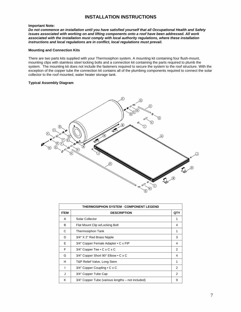
INSTALLATION INSTRUCTIONS Important Note: Do not commence an installation until you have satisfied yourself that all Occupational Health and Safety issues associated with working on and lifting components onto a roof have been addressed. All work associated with the installation must comply with local authority regulations, where these installation instructions and local regulations are in conflict, local regulations must prevail. Mounting and Connection Kits There are two parts kits supplied with your Thermosiphon system. A mounting kit containing four flush-mount, mounting clips with stainless steel locking bolts and a connection kit containing the parts required to plumb the system. The mounting kit does not include the fasteners required to secure the system to the roof structure. With the exception of the copper tube the connection kit contains all of the plumbing components required to connect the solar collector to the roof mounted, water heater storage tank. Typical Assembly Diagram
THERMOSIPHON SYSTEM · COMPONENT LEGEND
ITEM DESCRIPTION QTY
A Solar Collector 1
B Flat Mount Clip w/Locking Bolt 4
C Thermosiphon Tank 1
D 3/4" X 2" Red Brass Nipple 3
E 3/4" Copper Female Adapter • C x FIP 4
F 3/4" Copper Tee • C x C x C 2
G 3/4" Copper Short 90° Elbow • C x C 4
H T&P Relief Valve, Long Stem 1
I 3/4" Copper Coupling • C x C 2
J 3/4" Copper Tube Cap 2
K 3/4" Copper Tube (various lengths – not included) 9

8
Location Selection There are five major factors to consider when selecting the solar water heater installation location;
1. For optimum performance the solar collectors need to face the equator (in Southern hemisphere this is north and in the Northern hemisphere this is South). Installation on angles of up to 45° away from the equator do not have a major effect on the annual solar output, consequently roof locations which face less than 45° away from the equator are acceptable. If the collectors are installed with an east facing bias the best solar input is achieved in the morning and if there is a west facing bias the best solar input is in the afternoon.
2. Careful site inspection is required to ensure the selected location is not subjected to shading from adjacent
trees or buildings throughout the day but particularly between 9am and 3pm the highest solar input times. Shadows are longer in winter than in summer so a site that is free of shadows from adjacent objects in summer may have some shadows in winter.
3. The solar water heater is to be located a minimum of 3 foot up from the roofs lower edge, 3 foot in from
either side of the roof, and 3 foot down from the roofs ridge line and should be located as close as possible to the location which uses the most hot water e.g. bathroom or kitchen. This is to reduce energy losses which may occur if the pipe work between the solar water heater and the point of usage is too long.
4. To achieve optimum performance the solar water heater should be installed on a roof pitch of greater than
8° and less than 30°. Installations on a roof where the roof pitch is greater than 30° will require additional support at the storage tank to prevent it moving downward after installation. If the roof pitch is less than 8° the system will require a mounting frame to increase the pitch above 8°. Installations below 8° do not thermosiphon effectively and the collector glass will not self clean during rainy periods.
5. Careful inspection of the roof truss system is essential to ensure it can support the systems weight once
filled with water. Particular care must be taken where the front foot of the storage tank is located. Typically the tank front foot should be located over a tile batten, purlin or similar for maximum strength. If the roof can not support the load additional bracing must be installed before the solar water heater is installed.
Mounting Methods There are 3 methods of attaching the system to the roof structure; lag-bolts, J-bolts or spanner mounting.
NOTE: All mounting bolts, washers, split-lock washers & nuts are to be stainless steel.
Lag-Bolts – Lag-bolt mounting is the preferred method of install. The mounting clips are secured directly into the upper chord of the roof truss (the detail below shows an install using a triangular mount bracket). The lag-bolt must penetrate 3” into the structural member. A 2” deep pilot hole must be drilled into the truss with a 1/8” diameter bit before inserting the lag bolt.
Lag-bolt Mounting Detail
J-Bolts – J-bolt mounting is preferred in installations where the roof truss members are not easily identified from the outside of the roof. Clearance holes for the J-bolts are typically drilled from inside the attic space. Two install service personnel are typically required, one in the attic space and one on the roof, when installing J-bolts to insure the J-bolt is secured properly.

9
J-bolt Mounting Detail
Spanner mounting – Spanner mounting is by far the most common method of installation. Steel angle or wood 2” x 4”’s are used to span between the truss members. Two spacer blocks are required when the threaded rod is 2” or more from the truss member. Only one spacer block is required when the threaded rod is within 1” of the truss. Spacer blocks are to be no greater than 1” from the threaded rod.
Spanner Mounting Detail
Mounting the Collector(s) The collector installation procedure is as follows: (See also the diagram on page 7)
1. From the inside of the roof, in the attic crawl space, measure the center-to-center distance between the roof trusses. This distance is required to secure the mount clips to the collector prior to attaching the collector to the roof structure.
2. Position two (2) mount clips along each end of the collector (ends have no pipes – see the diagram) a
distance apart equal to the center-to-center roof truss spacing. Insure the mounts are centered across the collector ends and secure them with the locking bolts (multiple collector installations will require the mount clips to be slightly off center, this allows for the spacing between collectors).
3. Place the collector on the roof in the area selected for install.
4. Starting in the upper left-hand quadrant of the selected install area, locate the position of the nearest
roof truss. Measure down from the peak of the roof, a distance of 60” and make a mark on the roof tile. This will be the position of the top left mounting hole of the collector mount clip.
5. Using silicone caulk or roofing mastic, coat the underside of a roof mount flashing. Place the flashing
into position centered over the proposed mounting hole, insuring that the top of the flashing is under the upper roof tiles and the bottom of the flashing laps over the lower roof tiles. Secure the flashing using a couple of roofing nails under the upper roof tiles.
6. Drill an appropriately sized hole (as dictated by the method of attachment) into the roofing structure.

10
7. Place the collector into position with the upper-left mounting foot centered over the newly drilled hole
and align the collector to be square with the roof.
8. Using the installed mount clips as a template, mark the position of the remaining mount holes on the roof tiles then set the collector aside.
9. Secure flashings and drill holes for the remaining mount clips.
10. Using silicone caulk or roofing mastic, apply a liberal amount of sealant around the openings to all of the
newly drilled holes then place the collector into position and secure using the stainless steel hardware selected for the install method.
11. Check to insure that all mount connections are tight and prepare to mount the tank.
Mounting the Thermosiphon Tank The procedure for mounting the Thermosiphon tank is as follows: (See also the diagram on page 7)
1. Using the collector mounts as a reference, measure from the center of the upper mount bolts a distance of four (4) inches. Pop a chalk line connecting the two points and extending outward approximately one (1) foot on either side of the collector.
2. Position the Thermosiphon tank into place above and centered to the collector. Line up the mounting holes
(on the tank mount rail closest to the collector) centered on the marked chalk line. Mark the position of the mount holes and set the tank aside.
3. As with the collectors, secure flashings and drill holes for each of the mount locations. Apply a liberal
amount of sealant around the newly drilled holes.
4. Position the tank into place over the mount holes and secure using the appropriate stainless steel hardware.
5. Check to insure that all mount connections are tight. Apply a liberal amount of sealant over all of the mount hardware heads/threads (tank and collectors).
Plumbing Connections Assemble the hot/cold interface plumbing to the collector as shown in the detail on page 7. Various lengths of copper tubing is required and should be soldered together using lead-free solder. Service connections to the Thermosiphon system should include isolation and drain valves (not included) internal to the residence. Insure that the drain line from the Temperature and Pressure relief is plumbed to a safe location. Remember this pipe can discharge very hot water carefully consider its location.

11
ELECTRICAL INSTALLATION INSTRUCTIONS Note:
1. All electrical work must comply with local regulations 2. All electrical work must be conducted by a suitability licensed electrician.
Electrical Connection for Electric AES Systems The electric element is only connected in models using an electric AES system. No connection is made to the electric element for gas AES systems. The electrical booster requires a 220 – 250 volt single phase ac power supply with a capacity of 10 amps for a 1.8 kW element, 12 amps for a 2.4 kW element or 18 amps for a 3.6 kW element. The power supply must be protected by an individual fuse or circuit breaker at the main electrical supply switchboard and rated to suit the booster size. The supply to the solar water heater can be operated directly from the switchboard or via a remotely mounted switch or time clock as requested by the customer. Final electrical connection at solar water heater tank is made as follows: The Earth wire is connected to the earth stud marked with an earth symbol, the active wire connected to the thermostat terminal marked (L) and the neutral wire is connected to the thermostat terminal marked (N). Important Do not turn on the power supply until the solar water heater has been filled with water and pressurized. Electrical Circuit Diagram
Electrical Connection for Gas AES Systems: For models using a gas AES system the electrician is required to install a domestic electrical outlet socket adjacent the gas heater location. The gas heater requires a 220-240 volt 60 Hz power supply and is rated at 0.47 amperes.
GAS (AES) INSTALLATION INSTRUCTIONS
Note: 1. All gas work must comply with local regulations 2. All gas work must be conducted by a suitability licensed gas fitter. 3. Installation of the Gas Heater must be installed in accordance with the Installation supplied with
the Gas Heater. 4. TS DHW™ systems only use gas heaters manufactured by DUX, Rinnai or Bosch. 5. Particular attention must be given to the gas supply system to ensure the there is a sufficient gas supply
available to the gas heater when operating at full output burner rate. Approved Gas Heater Models: Following are the gas heater models which are approved for use with TS DHW™ solar water heater systems. Gas heaters other than those listed below must not be used with a TS DHW™ solar water heater. Dux Manufacturing:
Endurance SN16 Endurance SN24
Rinnai:
Infinity 16 Infinity 20
Bosch:
Highflow 17E Highflow 21E

12
Commissioning When all connections have been completed the solar water heater can be filled with water. Before turning on the cold water supply open one hot tap within the household to release air from the system during the filling process. Do not leave the open tap unattended during the filling process. Turn on the cold water supply and wait for the system to fill. When water flows without air bursts from the open hot tap it can be closed which will pressurize the solar water heater system. Once the system is pressurized all connections on the water heater must be checked for leaks and repaired if necessary. When the system is proven water tight, power and gas can be applied to the AES system. To test that the element is operational turn the circuit breaker in the switch board on and off, you should see the power meters speed change during this action. For gas AES systems turn on a hot water tap and the gas heater will ignite provided the water temperature is less than 60°C. The solar water heater is now fully operational. Customer Hand Over Once the solar water heater is commissioned and you are confident it is operating correctly complete the installation details in the Owners Instructions section of this manual and pass this manual and the gas heater manual (if used) to the customer. Before leaving the installation insure that the customer is fully aware of the systems operation and whom to contact should there be any questions in the future.