Seismic Retrofitting of Framed Structures With Stainless Steel

Framed Structures 2Objectives:
Differentiate between perfect, imperfect and redundant frames. To compute the member forces ina frame by graphical method. To compute the forces in a truss by method of joints. To computethe forces in a truss by method of sections. To compute the forces in a truss by method of tensioncoefficients.
2.1 PLANE FRAMESThe plane trusses are here by termed as plane frames. In this chapter, pin jointed plane frameswhich are statically determinate are considered. A statically determinate frame can be completelyanalysed by using statics. The number of unknown forces is the same as the number of equationsobtained from static equilibrium. The main methods in analysing statically determinate pin jointedplane frames are (i) Graphical solution – Force diagram (ii) Method of resolution at joints (iii)Method of sections and (iv) Tension coefficient method. The first three methods are used in planeframes (trusses) and the fourth method is used for analysing the space frame.
A truss is an assemblage of three or more members which are hinged or pinned. A load appliedon the truss is transmitted to all joints so that the members are in pure compression or tension.
Consider a simple truss made up of three members hinged at the ends to form a triangle. A loadW is acting at the apex of the triangle and due to symmetry, the reactions are W/2 at each support.
W
W/2W/2
B
A C
FIG. 2.1
Due to the application of the load, the joint A and C pulls the member out and for equilibrium atjoint A there should be an equal and opposite force should move away from joint A. In otherwords,member AC in tension. Due to the downward load W, the joint B is pushed vertically downwards.The forces in the members AB and BC are in compression as the joint B is pushed. A force in the

Framed Structures • 37
nm < 2n j −34 < (2×4)−34 < 5
B
A C
D
FIG. 2.3
n j = 4nm = 4
2.2.3 Redundant FrameA redundant frame is one where the number of member or members are more than (2 j − 3). InFig. 2.4, the number of joints are
nm > (2n j −3)
6 > (2×4)−36 > 5
B
A C
D
FIG. 2.4
n j = 4nm = 6
i.e.,’ redundant frame is having more member/members necessary to produce stability.
2.3 GRAPHICAL SOLUTION-FORCE DIAGRAMSConsider the perfect frame in Fig. 2.5. The forces include the applied load and the reactions atP and Q.
BA
P QC
50 kN
1
FIG. 2.5
Due to symmetry the reactions are 25 kN at joint P and Q respectively. In graphical method theloads and reactions are read clockwise. They are represented by capital letters written on either sideof the force, commonly known as ‘BOW’S Notation’. They are denoted with letters A,B,C and thespace inside the member is denoted by numbers. Note that the letters A,B,C are marked in the mid-dle length of the members and not at the joints. The load at the apex 50 kN is denoted as ‘load AB’.The reaction at the right support is denoted as ‘load BC’. The reaction at the left support 25 kN isdenoted as ‘load CA’. The member force in the horizontal member is denoted as ‘force 1C’.

38 • Basic Structural Analysis
The combined force diagram is drawn as follows:1. Starting from the force AB, the known forces, viz. AB,BC and CA working clockwise round
the frame, are set down in order and to scale as ab,bc and ca.2. Consider the apex joint ab the centre of the clock, and the letters are read clockwise around
this centre.3. Therefore, from the letter ‘b’ draw a line parallel to B1 and from the letter ‘a’ draw a line
parallel to 1A and both intersect at the point 1. From the force diagram, the magnitude ofthe forces are obtained. The member force A1 = Member force B1 = 5.7× 5 = 28.5 kN.Member force C1 = 2.8×5 = 14 kN.
4. Consider the joint at the left hand support reaction. Read clockwise in the frame diagram.Member A1 is inclined and in the force diagram a to 1 is downwards and hence mark thearrow correspondingly in the force diagram from 1 to C it is towards right mark this directionat that joint.
BA
C25
60°
50 kN
1
60°
25
FIG. 2.6 Frame diagram
5. Consider the apex joint. Read clockwise B1 is inclined member. In the force diagram, b to 1is upwards and hence mark the arrow upward for member B1 at the apex joint. Member 1Ais a sloping member. From the force diagram, 1 to a is upwards. Therefore, mark the arrowupwards at the apex joint. (compression).
5.7
cm
1 Scale 1 cm = 5 kNc
b
a
FIG. 2.7 Force diagram

Framed Structures • 39
6. Consider the right hand support reaction and again read clockwise. 1B is inclined member.In the force diagram 1 to b is downwards. Therefore, mark the arrow downwards at joint.
7. To determine the member force C1, from the force diagram it is noted that the force is actingfrom c towards left to 1. Mark the arrow C1 in the same direction in frame diagram.
The final forces are listed below.
Forces in kNMember Strut Tie
A1 28.5 −
B1 28.5 −
C1 − 14.0
2.3.1 Numerical Problems on Symmetrical Frame and Symmetrical Loading
EXAMPLE 2.1: Determine the forces in the members graphically.
B
C
D
E
A3 m3 m 3 mF G
20 kN
10 kN10 kN
FIG. 2.8
SOLUTIONDue to Symmetry:
VA = VB =10+20+10
2= 20 kN
Using the Bow notations
C
DA1 5
2 3 4
B
3 m3 m 3 mE
20 kN
10 kN10 kN
20 kN 20 kN
FIG. 2.9

40 • Basic Structural Analysis
The combined force diagram is drawn as follows:1. The loads AB, BC, CD, DE and EA are marked to scale.2. Start with a joint of the left hand reaction. Draw a line through the point ‘a’ a line parallel to
A1 and from the point ‘e’ draw a horizontal line parallel to 1E.They intersect at a point and is marked as 1.
3. Move to the next joint where 10 kN load is acting; Through ‘b’ draw a line parallel to B2 andfrom 1 draw a line parallel to 12. These two lines intersect at the point 2.
4. After locating point 2 in the force diagram. Consider the joint where the members 1−2,2−3, 3−E and E − 1 meet. The point 3 is located on intersection of line e1 and a line drawnthrough point 2 and parallel to 2−3 of the frame diagram.
5. The point 4 is located by drawing a line through 3 and parallel to 3−4 in the load diagramwhich intersects the line drawn from ‘C’ in the force diagram and parallel to C−4.
6. The point 5 is marked from point 4. Draw a line parallel to 4−5 of the frame diagram frompoint 4 and this cuts the horizontal line through ‘e’.
7. Using the force diagram, the magnitude of the forces and the directions are obtained.8. It is to be remembered that the arrows indicate not what is being done to the member but
what the member is doing at the joint at each end. Hence, if the arrow is acting towards thejoint it is compression and if the arrow is acting away from the joint then it is tensile force.
Force in kNMember Strut TieA1 D5 36.5 −
B2 C4 31.5 −
E1 E5 − 31.012 45 8.25 −
23 34 − 8.25
C
DA1 5
2 3 4
B
3 m3 m 3 m
E
20 kN
10 kN10 kN
FIG. 2.10 Frame diagram
5,1
2
3
4
a
b
e
c
d
FIG. 2.11 Force diagram

Framed Structures • 41
2.3.2 Numerical Example on Frame with Loads Suspended from the Bottom Chordof the Frame in Addition to Loads on the Top Chord
EXAMPLE 2.2: Find the forces in all the members of the truss graphically
3 m
60° 60°
10 kN
20 kN
3 m
3 m
10 kN
FIG. 2.12
1. The loads AB, BC, CD, DE and EA are marked to scale.2. Start with the left support joint. Read clockwise and draw. Draw a line from ‘a’ parallel to
A−1 in the load diagram. Draw another line e from the load diagram and parallel to the 1Eof the frame diagram. They intersect at the point 1.
3. The point 2 is located by considering the joint adjacent to the left support. Draw a line frompoint 1 parallel to 1−2 of the frame diagram. From the load diagram, draw a horizontal linethrough d and the line intersect at point 2.
4. From the point 2 draw a line parallel to 2−3 of the frame diagram and from point ‘e’ drawa horizontal line and the intersection of above two lines give point 3.
5. Determine the magnitude and nature of the forces from the forces diagram and tabulate.
A
10
20 kN
20
B
D
CE
10
201
2
3
FIG. 2.13 Frame diagram
a,c
b,e
d
1
2
3
FIG. 2.14 Force diagram

42 • Basic Structural Analysis
Force in kNMember Strut Tie
A1 12.5 −
B3 12.5 −
12 11.8 −
23 11.8 −
1E − 24.02D − 18.53C − 24.0
2.3.3 Numerical Example on Cantilever FramesEXAMPLE 2.3: Use the graphical method and determine the member forces and the reaction atthe supports.
B
25 kN50 kN
4 m4 m
6 m
FIG. 2.15
In the force diagram of the cantilever truss, these is no need of reactions before starting of the same.
1. The load line is drawn as in the previous examples. a−b, b− c, start with a joint at the freeend and reading clockwise, draw line from b parallel to B3 of the frame diagram and frompoint C draw line parallel to C3 and the intersection of the above lines give point 3.
2. The point 2 is located as follows. From the point 3, draw a line parallel to 23 and from ‘a’draw a line parallel to A2. The intersection gives the point 2.
3. The point 1 is obtained as follows. A line is drawn from point 3, parallel to 3−C and frompoint 2 draw line parallel to 21 and the intersection of 1.
4. After marking the points 1, 2 and 3 the member forces and their nature are tabulated here.

Framed Structures • 43
A B 25 kN50 kN
4 m4 m
6 m
2
1
3
C
D
FIG. 2.16
2
1
3
Reaction at the top hinge
Reaction at the rollerc
a
b
d
FIG. 2.17
Force in kNMember Strut Tie
A2 − 36B3 − 36C3 43 −
C1 86 −
12 − 41.51D − 50.023 50 −
Reaction at hinge 103 −
Reaction at roller 66 −
2.4 METHOD OF JOINTS
In the method of joints, the member forces are determined using the equilibrium conditions atthat particular joint. In this resolution of forces at the joint, the free body diagram at that joint isconsidered. The procedure is explained as follows:

44 • Basic Structural Analysis
1. Check the stability and assess its determinacy of the truss.2. If the truss is of cantilever type, the reactions need not be computed in general. If the truss
is stable and determinate where one support is hinge and the other support is on rollers;compute the reactions at the supports.
3. Draw the free body diagram at each joint and analyse the member forces at a joint whereonly two members meet. Then, consider the adjacent joint where only two unknown forcesto be determined. This process is repeated till the analysis of all joints are completed.
4. The results are tabulated along with magnitude of member forces and the nature of forces.The forces are tensile if they are pulling (acting away) the joint. The forces are compressivein nature if they are pushing (acting towards) the joint.
NUMERICAL EXAMPLEEXAMPLE 2.4: Analyse the truss shown in Fig. 2.18 by method of joints. (May 2010, RVCE)
2
70 kN
1
4 65
20
H4
V4
3
3 m
3 m3 m
V6
FIG. 2.18
SOLUTIONThe reactions at the supports are found out by summing up the forces in horizontal and verticaldirections and also by taking moments of applied forces about the hinge support.
∑H = 0; 20−H4 = 0
H4 = 20 kN
∑V = 0; V4 +V6 = 70 kN
∑M4 = 0; 20×3+70×3−6V6 = 0
V6 = 45 kN
∴ V4 = 25 kN

Framed Structures • 45
Joint 4
∑H = 0;F45 −20 = 0F45 = 20 kN
∑V = 0;−F14 +25 = 0F14 = 25 kN
4
F14
F45
25 kN
20
Joint 1
∑V = 0;25−F15 sin45 = 0F15 = 35.4 kN
∑H = 0;20−F12 +F15 cos45 = 020−F12 +35.4cos45 = 0F12 = 45.03 kN
1
F15
F12
25 kN
20 kN
45°
Joint 2
45.03−F23 = 0F23 = 45.03 kN
∑V = 0; F25 = 70.0 kN F25
F23
70 kN
45.03
2
Joint 5
F53
70 kN
20
35.4
5
45°
45°
∑V = 0;F53 cos45+35.4sin45−70 = 0F53 = 63.61 kN

46 • Basic Structural Analysis
Hence the final forces are
2
70 kN
1
4 65
20 kN
20
3
3 m
20
25
45 45
4563.61
7035.4
FIG. 2.19
EXAMPLE 2.5: Analyse the truss shown in Fig. 2.20 by method of joints. Indicate the memberforces on a neat sketch of the truss. (MSRIT, Jan. 2010)
BD
θ1
FA
4 m
E3 m 3 m
20 kN
C
4 m
FIG. 2.20
SOLUTIONTaking moment about the hinge at A;
∑MA = 0; 20×6−8HC = 0HC = 15 kN
∑H = 0; ∴ HA = 15 kN
∑V = 0; VA = 20 kN

Framed Structures • 47
Joint E
θ
FDE
FEF
20 kN
E
∑V = 0; FDE sinθ = 20
FDE =200.8
= 25 kN
FEF = FDE cosθ = 25×35
= 15 kN
Joint A
FAB
FAF
20 kN
15 A
∑H = 0;FAF = 15 kN
∑V = 0; FAB = 20 kN
Joint C
θ1
FCD
15 kNC
FBC
∑H = 0; FBC sinθ1 = 15
FBC =150.6
= 25 kN
∑V = 0; −FCD +FBC cosθ1 = 0FCD = FBC ×0.8FCD = 25×0.8 = 20 kN
Joint D
20 kN
FDB
FDF
25 kN
θ
D
∑H = 0;25cosθ−FDB = 0
FDB = 25×35
= 15 kN
∑V = 0;20+FDF −25sinθ = 0
20+FDF −25×0.8 = 0FDF = 0

48 • Basic Structural Analysis
Joint F
15 kN FFEF
FBF
FDF ∑V = 0;
FDF = 0
20
15
A
B
C
D
EF
25
25
15
20 kN
15
20
FIG. 2.21
EXAMPLE 2.6: Find the forces in all members of the pin jointed truss shown in Fig. 2.22 byusing method of joints. (VTU, June 2009)
2 kN
3 m
60° 60°
3 m
4 kN
A
B C
DE
FIG. 2.22
∑V = 0;VA +VD = 2+4 = 6 kN

Framed Structures • 49
∑MA = 0;2(1.5)+4(4.5)−6VD = 0VD = 3.5 kNVA = 2.5 kN
Consider Joint A
FAB
FAE
2.5 kN
A60°
∑V = 0FAB sin60 = 2.5FAB = 2.89 kN
∑H = 0FAE = FAB cos60= 2.89cos60= 1.45 kN
Joint D
FCD
FDE
3.5 kN
60°D
∑V = 0FCD sin60 = 3.5FCD = 4.04 kN
∑H = 0FCD cos60−FDE = 0FDE = 4.04cos60 = 2.02 kN
Joint E
FEB
FEC
1.45 kN E 2.02 kN
60° 60°
∑V = 0FEC sin60+FEB sin60 = 0FEC = −FEB
∑H = 02.02+FEC cos60−1.45−FEB cos60 = 02.02−FEB cos60−1.45−FEB cos60 = 00.57 = 2FEB cos60FEB = 0.57; FEC = −0.57

50 • Basic Structural Analysis
Joint C
FCE
FBC
4 kN
FCD
= 4.04 kN
60° 60°
C
∑H = 0;FBC −FCE cos60−FCD cos60 = 0FBC −FCE cos60 = 4.04cos60
∑V = 0;−4−FCE sin60+4.04sin60 = 0FCE = −0.57 kN
Substituting FCE in the above equation
FBC = 1.73 kN
2 kN
1.45
1.73
0.572.89 0.57 4.04
2.02
4 kN
A
B C
DE
FIG. 2.23
EXAMPLE 2.7: Determine the magnitude and nature of forces in all the number of the pin jointedplane truss shown in Fig. 2.24 by method of joints. (VTU, June 08)
6 m
A
E
B C
D
4 m
25 kN 50 kN 25 kN
4 m
FIG. 2.24

52 • Basic Structural Analysis
∑V = 0;
−50−41.67sinθ+FAD cosθ1 +FDE sinθ = 0
−50−41.67(0.6)+0.6FAD +0.6FDE = 0
0.6FAD +0.6FDE = 75
FDE +FAD = 125 (2.2)
Solving Eqns. (1) and (2);FDE = 83.3 kN, FAD = 41.67 kN
Joint E
83.3
FAE
θ2
E
tanθ2 = 8/6
sinθ2 = 0.8
cosθ2 = 0.6
∑V = 0; FAE = 83.3cosθ2 = 50 kN
50
A
E
B C
D
33.3
8.33
41.6741.67 50
25 kN 50 kN 25 kN
33.3
FIG. 2.25

Framed Structures • 53
EXAMPLE 2.8: Analyse the truss shown in Fig. 2.26 by method of joints. (VTU, May 2008)
A B C D E
F H
G
30 kN
3.6 m
4.8 m
θ θ
θ1
θ1
θ θ
30 kN60 kN4.8 m 4.8 m 4.8 m 4.8 m
FIG. 2.26
SOLUTION
Due to Symmetry: VA = VE =2(30)+60
2= 60 kN
Consider Joint A
θ
60 kN
FAB
FAF
A ∑V = 0; FAF sinθ = 60FAF ×0.6 = 60FAF = 100 kN
∑H = 0; 100cosθ−FAB = 0FAB = 100×0.8 = 80 kN
Joint B
30 kN
80 kN
FBF
FBC
B
∑V = 0FBF = 30 kNFBC = 80 kN

Framed Structures • 55
EXAMPLE 2.9: Determine the forces in members and tabulate neatly. Use method of joints.(VTU, Dec. 06)
8 kN
H
8 kN
4 kN
C
F
D EA
8 kN
4 kN2 m
G
Bθ
4 m
3 m 3 m 3 m 3 m
FIG. 2.28
SOLUTION
Due to Symmetry: VA = VB =2(4)+3(8)
2= 16 kN
Joint A
16 kN
4 kN
FAF
FAC
θA A
∑V = 0−4−FAF sinθ+16 = 012−0.555 FAF = 0FAF = 21.62 kN
∑H = 0FAC −FAF cosθ = 0FAC = 21.62×0.832 = 18.0 kN
Joint C
18.0
FCD
C
∑H = 0;FCD = 18.0 kN

56 • Basic Structural Analysis
Joint F
21.62
8 kNF
FH
FFD
θ
θθ
F
∑V = 0−8+21.62 sinθ−FFH sinθ+FFD sinθ = 0−8+21.62×0.555−0.555 FFH +0.555 FFD = 00.555 FFD −0.555 FFH = −4
∑H = 0;21.62cosθ−FFH cosθ−FFD cosθ = 0FFD +FFH = 21.62FFD = 7.21, FFH = 14.41 kN
Joint H
14.41F
HD
8 kN
14.41
θθ
H
∑V = 0−8+14.41sinθ+14.41sinθ+FHD = 0FHD = 8−16 = −4 kN∴ FHD = −4 kN
This shows that the direction is to be changed, i.e., FHD is tensile
S.No Member Force (kN) Nature1 AF 21.62 Compressive2 FH 14.41 Compressive3 HG 14.41 Compressive4 GB 21.62 Compressive5 BE 18.00 Tensile6 ED 18.00 Tensile7 DC 18.00 Tensile8 AC 18.00 Tensile9 CF 0.00 –
10 FD 7.21 Compressive11 DH 14.41 Compressive12 DG 7.21 Compressive13 GE 0.00 –

58 • Basic Structural Analysis
Joint D
θ1
30 kN
D120
FDB
FDE
∑V = 0FDB sinθ1 −30 = 0
FDB =30
0.707= 42.43 kN
∑H = 0−120+FDE +42.43cosθ1 = 0
FDE = −42.43×0.707+120 = −30 kN+12090 kN
1.25 m
2.50 m
134.17
134.17
30 kN 30 kN
60 kN
90120 DA
B
C
HG
E F
42.4330
FIG. 2.30
EXAMPLE 2.11: Determine the forces in all members of all Bollman truss by method of joints.(VTU, July 2005)
20 kN 20 kN 20 kN
10 m 10 m 10 m 10 mA B
HG
C D E
F
θ1θ
1θ
2
θ3
10 m
FIG. 2.31

Framed Structures • 59
SOLUTIONDue to Symmetry
VA = VB =3(20)
2= 30 kN
From geometry
tanθ1 =1030
tanθ2 = 10/20 tanθ3 = 10/10sinθ1 = 0.316 sinθ2 = 0.447 sinθ3 = 0.707cosθ1 = 0.949 cosθ2 = 0.895 cosθ3 = 0.707
Joint C,D,EFCF = 20 kN, FDG = 20 kN, FEH = 20 kN
20 kN
FCF
C
Joint F
θ1
θ3
20 kN
FFB
FFA
F
∑H = 0;−FFA cosθ3 +FFB cosθ1 = 0−0.707FFA +0.949FFB = 0
∑V = 0;−20+FFA sinθ3 +FFB sinθ1 = 00.707FFA +0.316FFB = 20
on solving the above equations
FFA = 21.22 kNFFB = 22.37 kN
Joint G
θ2
θ2
20 kN
FGB
FGA
G
∑H = 0;−FGA cosθ2 +FGB cosθ2 = 0FGA = FGB
∑V = 0;−20+FGA sinθ2 +FGB sinθ2 = 02 FGA sinθ2 = 202 FGA(0.447) = 20FGA = 22.37 kN
15.81 kN

Framed Structures • 61
Joint A
θ
50 kN
FAD
FAE
tanθ = 5/6; θ = 39°48′
A ∑H = 0
50−FAD sinθ = 0
FAD =50
0.64= 78.1 kN
∑V = 0
FAE −78.1cosθ = 0
FAE = 60.0 kN
Joint E
60
60 kN
FEC
FDE
E
∑V = 0;
−60+FEC = 0
FEC = 60 kN
∑H = 0;
FDE = 0
Joint D
∑H = 078.1cos(90−θ)−FDC cosθ−FDB cos(90−θ) = 0
θ(90–θ)
(90–θ)
FDCF
DB
78.1
D
78.1cos50◦11′ −FDC(0.768)−0.64 FDB = 0
0.768 FDC +0.64 FDB = 50.01
∑V = 0
78.1sin (90−θ)+FDC sinθ−FDB sin (90−θ) = 0
60+0.64 FDC −0.768 FDB = 0
0.64 FDC −0.768 FDB = −60
FDC = 0, FDB = 78.1 kN

Framed Structures • 63
SOLUTION
AD =√
AH2 +DH2
DH = 6tan30
=√
62 +3.462 = 6.93 m
AC = CD =6.93
2= 3.465 m
The reactions are found as
∑V = 0;VA +VB = 10sin60+20sin60+10sin60+10VA +VB = 44.64
∑MA = 0;20×3.465+10×6.93+10(4)−12VB = 0VB = 14.88 kNVA = 29.76 kN
Consider Joint A
∑H = 010 cos60+20 cos60+10 cos60−HA = 0
HA = 20 kN
FAC
FAE
29.76 kN
20 kN
60° 30°
10 kN
A
∑H = 0;10cos60−20+FAE −FAC cos30 = 0FAE −0.866 FAC = 15
∑V = 0−10sin60+29.76−FAC sin30 = 0
FAC = 42.2 kN∴ FAE = 51.55 kN
Joint B
FBG
FBF
14.88 kN
30°B
∑V = 0;−FBG sin30+14.88 = 0FBG = 29.76 kN
∑H = 0;FBG cos30−FBF = 0FBF = 25.77 kN

64 • Basic Structural Analysis
Joint C
FCD
FCE
60°
60°
30°
30°
20 kN
42.2
C
∑H = 020cos60−FCD cos30−FCE cos60+42.2cos30 = 0FCD cos30+FCE cos60 = 46.550.866 FCD +0.5 FCE = 46.55
∑V = 0−20sin60−FCD sin30+FCE sin60+42.2sin30 = 0−0.5 FCD +0.866 FCE = −3.78FCD = 42.20 kNFCE = 20.00 kN
Joint G
30°
60°30°
FGB
= 29.76
FGD
FGF
G
∑H = 0FGD cos30−FGB cos30+FGF cos60 = 00.866 FGD −0.866 FGB +0.5 FGF = 00.866 FGD +0.5 FGF = 0.866×29.760.866 FGD +0.5 FGF = 25.77
∑V = 0−FGD sin30+FGF sin60+29.76sin30 = 0−0.5 FGD +0.866 FGF = −14.88FGD = 25.77 kN, FGF = 0
Joint D
60°
60°
60°
30°30°
25.77
10 kN
42.20
FDE
D
∑V = 0;−10sin60+42.20sin30−FDE sin60+25.77sin30 = 0FDE = 29.24 kN
kN

66 • Basic Structural Analysis
Joint F
θ
10
FCF
FFD
F ∑H = 010−FCF sinθ = 0
tanθ = 4/3 FCF = 12.5 kNsinθ = 0.8 ∑V = 0cosθ = 0.6 FFD −FCF cosθ = 0
FFD = 7.5 kN
Joint C
20 kN
12.5
θ
FAC
FCD
C
tanθ = 3/4sinθ = 0.6cosθ = 0.8
∑H = 0;20+12.5cosθ−FCD = 020+12.5×0.8 = FCD
FCD = 30 kN∑V = 0;
−FAC +12.5sinθ = 0FAC = 12.5×0.6 = 7.5 kN
Joint D
θ1
θ
30
7.5
D
FDA
FDB
∑H = 0;30−FDA sinθ = 0
FDA =30
sinθ=
300.8
= 37.5 kN
∑V = 0;−7.5+FDB −FDA cosθ = 0−7.5+FDB −37.5×0.6 = 0FDB = 30.0 kN

68 • Basic Structural Analysis
Consider Joint F
60°
6 kN
F
FFC
FEF
∑V = 0FFC sin60 = 6
FFC =6
sin60= 6.93 kN
∑H = 0FEF −FFC cos60 = 0FEF = 6.93 cos60
= 3.47 kN
Joint C
C
60° 12 cos 60°
6.93
12 sin 60°F
BC
FEC
∑V = 0−12sin60−6.93sin60+FEC sin60 = 0FEC = 18.93 kN
∑H = 0FBC +18.93cos60+6.93cos60−12cos60 = 0FBC = −13.86cos60FBC = 6.93 kN
Joint E
3.47
18.93
60°60°
FDE
FBE
E
∑V = 0FBE sin60−18.93sin60 = 0FBE = 18.93 kN
∑H = 0−3.47−18.93cos60+FDE −18.93cos60 = 0FDE = 22.4 kN
Joint B
B
18.93
6.93FAB
FBD
60° 60°
∑V = 0−18.93sin60+FBD sin60 = 0FBD = 18.93 kN
∑H = 06.93+18.93cos60+18.93cos60−FAB = 0FAB = 25.86 kN

70 • Basic Structural Analysis
SOLUTIONThe reactions are found using the equilibrium equations.Summing up all the forces in the vertical direction;∑V = 0;
VA +VF = 50+40VA +VF = 90 (1)
∑MA = 0;
50(6)+40(9)−6VF = 0VF = 110 kN
∴ VA = 90−110 = −20 kN
This means that the direction of VA is downwards.Joint A
FAH
FAB
20 kN
A
θ
Considering the joint A; a vertical downward force of 20 kN is acting down. To balance this thereshould be an upward force of 20 kN to balance. This is due to FAH since FAB is a horizontal forcewhich do not give a vertical component.
∴ FAH sinθ = 20
FAH =20
sinθ= 36 kN
Resolving the forces horizontally at the joint A;
FAB = FAH cosθ
= 36×0.832= 29.95 kN
Joint E
tanθ1 = 4/3sinθ1 = 0.8cosθ1 = 0.6
40 kNF
DE
FEF
θ1 E

Framed Structures • 71
Resolving vertically,
FEF sinθ1 = 40
FEF =400.8
= 50 kN
Resolving all the forces in the horizontal direction
FDE = FEF cosθ1 = 50×0.6 = 30 kN
Joint FThe truss is supported on rollers at the joint F . Only one reaction will be acting perpendicular tothe base of the roller. Hence,
110 kN
FDE
FGF
FFE
= 50 kN
F
θ1
θ
∑H = 0;FGF cosθ−50cosθ1 = 0FGF = 50×0.6/0.832FGF = 36.06 kN
∑V = 0;110−36.06sinθ−50sinθ1 +FDF = 0FDF = 36.06(0.555)+50(0.8)−110= −50 kN
The −ve sign indicates that we have to change the nature of the force in FDF and hence FDF iscompressive.
Joint B
FBH
29.95 kN FBCB
B
Resolving all the forces meeting at the joint in the vertical direction and as no forces are acting inthe vertical direction; FBH = 0. Resolving the forces at the joint B along the horizontal directionFBC = 29.95 kN

72 • Basic Structural Analysis
Joint H
FCH
FHC
36 kN
H
A, H and G are on the same line. Hence, resolving the forces meeting at the joint H, A HGResolving all the forces along the line, FHG = 36 kNJoint C
FCD
FCG
29.95 kN C
Resolving all the forces in the vertical direction: FCG = 0Resolving all the forces in the horizontal direction: FCD = 29.95 kNJoint G
FGD
FGF
36 kN
G
Resolving all the forces meeting at the joint G, along the line HGF and perpendicular that line;
FGD = 0;FGF = 36 kN
74 • Basic Structural Analysis
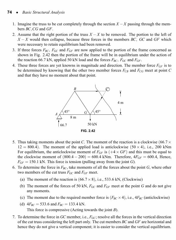
1. Imagine the truss to be cut completely through the section X −X passing through the mem-bers BC,CG and GF .
2. Assume that the right portion of the truss X −X to be removed. The portion to the left ofX −X would then collapse, because three forces in the members BC, GC and GF whichwere necessary to retain equilibrium had been removed.
3. If three forces FBC, FGC and FGF are now applied to the portion of the frame concerned asshown in Fig. 2.42 then the portion of the frame will be in equilibrium under the action ofthe reaction 66.7 kN, applied 50 kN load and the forces FBC, FGC and FGF .
4. These three forces are yet knowns in magnitude and direction. The member force FGF is tobe determined by knowing that the other two member forces FCB and FCG meet at point Cand that they have no moment about that point.
8 m
66.7 50 kN
45°
4 m
A
B C
G 45°
FIG. 2.42
5. Thus taking moments about the point C. The moment of the reaction is a clockwise (66.7×12 = 800.4). The moment of the applied load is anticlockwise (50 × 4), i.e., 200 kNmFor equilibrium, the anticlockwise moment of FGF is (+4×GF) and this must be equal tothe clockwise moment of (800.4− 200) = 600.4 kNm. Therefore, 4FGF = 600.4, Hence,FGF = 150.1 kN. This force is tension (pulling away from the joint G).
6. To determine the force in FBC, take moments of all the forces about the point G, where othertwo members of the cut truss FGC and FGF meet.
(a) The moment of the reaction is (66.7×8), i.e., 533.6 kN, (Clockwise)(b) The moment of the forces of 50 kN, FGC and FGF meet at the point G and do not give
any moments.(c) The moment due to the required member force is (FBC ×4), i.e., 4FBC (anticlockwise)(d) 4FBC = 533.6 and FBC = 133.4 kN.
This force is compressive (Acting towards the joint B).
7. To determine the force in GC member, i.e., FGC; resolve all the forces in the vertical directionof the cut truss considering the left part only. The cut members BC and GF are horizontal andhence they do not give a vertical component; it is easier to consider the vertical equilibrium.

Framed Structures • 75
The reaction at A is 66.7 kN acting upwards and hence it is taken as negative. The appliedload at G is 50 kN and is acting downwards and therefore it is positive. The vertical compo-nent due to FGC is downwards, i.e., FGC sin45. This is negative.Summing up all the above forces in the vertical direction and equating upward forces todownward forces.
FGC sin45+50 = 66.7∴ FGC = 23.62 kN.
This is compressive as the force is acting towards the joint.8. It must be remembered that the arrows must be considered in respect to the nearest point of
that portion of the frame which remains after the cut has been made.
2.5.2 Numerical ProblemsEXAMPLE 2.17: Determine the nature and magnitude of forces in members DE,DIand HI of the truss shown in Fig. 2.45 by using method of sections.
3 kN 6 kN 6 kN 3 kN
DC EB
G
VA V
F
6 m
60°A F
6 kN
H
12 kN
I
6 kN
6 m6 m 6 m
X
X
60°
FIG. 2.43
SOLUTION
∑V = 0 VA +VF = 42
∑MA = 0 3(3)+6(9)+6(15)+3(21)+6(6)+12(12)+6(18)−24VF = 0VF = 21 kN∴ VA = 21 kN

Framed Structures • 77
EXAMPLE 2.18: Determine the forces in the members BC, FC and FG by method of sections.
30 kN
B
F H
G
60 kN
C
30 kN
D
4.8 4.8 m
EA
4.8 4.8
4.8 m
3.6
FIG. 2.45
SOLUTIONDue to symmetry, the reactions
VA = VE =30+60+30
2= 60 kN
To determine the forces in BC, FC and FG cut a section X-X as shown in Fig. 2.48Consider left part of the truss and analyse the equilibrium.
60 kN
30 kN
θ
θ
θ1
θ
4.8 4.8
3.6
X
X
CA B
F
FIG. 2.46
To determine the force in BC, take moment about ‘F’ where other two members of the cutsection FC and FG meet.
60×4.8 = FBC ×3.6FBC = 80 kN

78 • Basic Structural Analysis
30 kN
θ
θ1
θ
4.8 m
3.6 m
C
G
A
60 kN
B
F �
A �
F
FIG. 2.47
From geometry A′C = 19.2 m
To determine the force in FC, take moment about A′ where the other two members of the cutsection BC and FG meet.Let A′F ′ be perpendicular to the line CF extended.
sinθ =A′F ′
A′CA′F ′ = 19.2×0.6 = 11.52 m
∑M ′A = 0
−60× (A′A)+30 (A′B)+FFC (11.52) = 0−60×9.6+30 (19.2−4.8) = −11.52 FFC
∴ FFG = 12.5 kN (Compressive)
To determine the force in FG, take moment about C where the members BC and FC meet.
θ2
6 m
F
C′
C
FIG. 2.48
In Fig. 2.45, FC =√
BC2 +BF2
=√
4.82 +3.62 = 6 m

80 • Basic Structural Analysis
Cut a section through the members CD, CG and FG and consider the right part of the truss.
EF
FG
FCD
G 3 m
D
G′
60°
2.88
30°
X
X
C
FCG
FIG. 2.50
tan30 = GD/2.6GD = 2.6tan30 = 1.5 m
To determine the force in CD, take moment of the forces in the cut truss about G where othertwo members of the cut section, viz. CG and FG meet.
1.5 FCD = 2.88×3FCD = 5.76 kN
To determine the force in FG, take moment about C where other two members of the cutportion of the truss, viz. CD and GC meet.
4.5tan30 (FFG) = 2.88×4.5FFG = 4.98 kN
To determine the force in GC, take moment about E where the cut members CD and FG meet.Let EG′ is perpendicular to the line CG extended
∴ FCG ×G′E = 0FCG = 0

Framed Structures • 81
EXAMPLE 2.20: Find the forces in the members ED, EF and FG. Use method of sections.(VTU, Aug. 2004)
B
D
CG
A
10 kN
4 m
30° 60°60°
4 m4 m
E FH
10 kN
10 kN
20 kN
FIG. 2.51
SOLUTIONThe length of panel AC, CD are found using geometry.
cos30 = 6/AD
AD = 6/cos30
= 6.93 m
∴ AC = CD = AD/2
= 3.46 m
The reactions VA, HA and VB are determined using the equilibrium equations.
∑H = 0;
10cos60+20cos60+10cos60−HA = 0
HA = 20 kN
∑V = 0;
VA +VB = 10sin60+20sin60+10sin60+10
VA +VB = 44.64 kN
∑MA = 0;
20(3.46)+10(6.92)+10(4)−12VB = 0
VB = 14.87 KN
To determine the forces in the members CD, DE and EF cut a section through these members andfor convenience consider the right part of the truss.

Framed Structures • 83
∑MB = 0
FFG ×GB = 0
∴ FFG = 0
EXAMPLE 2.21: Determine the forces in the members FE, FD, CD of the truss shown in Fig.2.54
B
E
F
A3 m 3 m 3 mC D
50 kN
3 m
FIG. 2.54
SOLUTIONThe reactions are found out by using equilibrium equations.
VA +VB = 50
Taking moment about A;
50×3−9VB = 0
VB = 16.7 kN; VA = 33.3 kN
To determine the forces in FE, FD and CD, cut a section through these members and consider theright-hand portion of the truss.
FCD ×3 = 16.7×6
FCD = 33.4 kN
To determine the force FFE; take moment about D; where other two members of the cut truss,FFD and FCD meet.

84 • Basic Structural Analysis
FCD
FFD
VB
FFE
E
DB
D′
θ
6 m3 m
16.7 kN
F
3 m
FIG. 2.55
tanθ = 3/6i.e. θ = 26◦33′54′′
.
In ∆ BDD ′
sinθ =DD ′
DB∴ DD ′ = 3sin26◦33′54′′
.
= 1.34 m.
FEB ×1.34 = 16.7×3FEB = 37.4 kN
To determine the force in FD, take moment about B where other two members of the cutsection, viz. FFE and FCD meet.Extend FD downwards to B′ such that BB′ is perpendicular to the projected line of FD. Consideringthe ∆DBB′;
sinθ =BB′
3BB′ = 3sinθ = 3× sin26◦33′54′′
.
BB′ = 1.34 m
∑MB = 0; FFD ×BB′ = 0FFD = 0

86 • Basic Structural Analysis
15 kN
θ
FEF
FDE
E
Consider Joint F
FFFG
59.8
FFD
At joint F , there is no vertical force acting. Hence, resolving the forces in the vertical directionFFD = 0. Resolving the forces in the horizontal direction,
∑H = 0; FFG −59.8 = 0FFG = 59.8 kN
Consider Joint D
D
FDC
FDE
= 61.73FDG
At joint D; resolving the forces perpendicular tothe line CDE, FDG = 0 as the forces FDC andFDE cannot give components in the perpendic-ular direction. Resolving the forces along theline of forces. FDE the force FDC is obtained asFDC = 61.73 kN.
Joint G
G
FGC
FAG 59.8
Resolving the forces in the vertical direction atjoint G; FGC = 0 and resolving the forces in thehorizontal direction FAG = 59.8 kN.

88 • Basic Structural Analysis
EXAMPLE 2.23: A truss of 10 m span is loaded as shown in Fig. 2.58 find the forces in themembers of the truss by using method of sections.
C
B
A
30 kN
25 kN
GF E
10 m
D60° 60° 60° 30°
FIG. 2.58
SOLUTION
∑V = 0 sin30 =AB10
VA +VD = 25+30 AB = 10sin30
VA +VD = 55 kN AB = 5 m
∑MA = 0 cos30 =BD10
25×5cos60+30×6.25−10VD = 0 BD = 8.66 mVD = 25 kN BC = CD = 4.33 m
VA = 30 kN AF = 5cos60AG = 10−4.33cos60
AG = 6.25 m
In ∆CGD
sin30 =CGCD
CG = CDsin30 = 4.33sin30 = 2.165 m
G
Framed Structures • 89
In ∆CGE;
sin60 =CGCE
CE = CG/sin60 = 2.165/sin60CE = 2.5 m
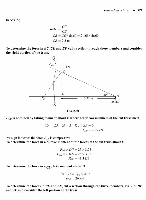
To determine the force in BC, CE and ED cut a section through these members and considerthe right portion of the truss.
30 kNF
CB
25 kN
G
E
C
3.75 mD30°
X
X
FIG. 2.59
FCB is obtained by taking moment about E where other two members of the cut truss meet.
30×1.25−25×5−FCB ×2.5 = 0FCB = −35 kN
-ve sign indicates the force FCB is compressive.To determine the force in DE, take moment of the forces of the cut truss about C.
FDE ×CG = 25×3.75FDE ×2.165 = 25×3.75
FDE = 43.3 kN
To determine the force in FCE, take moment about D.
30×3.75 = FCE ×4.33FCE = 26 kN.
To determine the forces in BE and AE, cut a section through the three members, viz. BC, BEand AE and consider the left portion of the truss.

Framed Structures • 91
Joint D
30°
25 kN
FCD
FED
D
∑V = 0
25 = FCD sin30
FCD = 50 kN
C
B
A
30 kN
35
26 kN
25 kN
43.3 kN
34.6 kN
50
26 kN
17.32 kN E
10 m
D60° 60° 60°
FIG. 2.61
EXAMPLE 2.24: Figure 2.62 shows a pinjointed truss supported by a hinge at A and roller at G.Determine the force in each of the five members meeting at joint B.
B C D E F
H GIJK180 kN4 m
LA45º 45º
125 kN
6 @ 4 m
4 m
FIG. 2.62

92 • Basic Structural Analysis
The reactions at A and G are found by using vertical equilibrium equations and moment equilibrium.
∑V = 0; VA +VG = 180+125VA +VG = 305
∑MA = 0; 180×4+125×8−24VG = 0VG = 71.7 kNVA = 233.3 kN
At the joint B, there are five members meeting, viz. BA, BL, BK, BJ and BC. The method ofobtaining the forces is by using method of joints as well as method of sections. The forces BA andBL are obtained by using method of joints at A and L. The force in BJ is determined by method ofsections. Then the member forces BC and BK are obtained by resolution forces at the joint B.
Joint A
45°
233.3 kN
FAL
FAB
A
Resolving the forces verticallyFAB sin45 = 233.3
FAB = 329.9 kNResolving the forces horizontally
FAL = FAB cos 45
FAL = 233.3 kN
Joint L
FLB
180 kN
L
Resolving the forces verticallyFLB −180 = 0
FLB = 180 kN

Framed Structures • 93
To determine the force in BJ, cut a section through CD, BJ and KJ.
B C
AK
180 kN233.3
L
J
FBJ
125 kN
45° θ
X
X
FIG. 2.63
tanθ = 4/8sinθ = 0.4472
In the cut truss, two cut members, viz. CD and KJ are horizontal. They do not give any verticalcomponent of the force. Hence to maintain equilibrium in the vertical direction, the force FBJ whichis indirect at an angle θ should give a vertical component to balance the effect due to the verticalreaction at A and the applied downward loads. Hence resolving vertically.
FBJ sinθ+233.3−180−125 = 0.
FBJ = 160.33 kN
Using method of joints at joint B (as shown in Fig. 2.64)
B
45°
329.9
180
106.33
FBC
FBK
θ
FIG. 2.64
∑H = 0; 329.99 cos45−FBC +160.33 cosθ−FBK cos45 = 0FBC +0.707 FBK = 376.74
kN
kN
kN

Framed Structures • 95
30° 60°
G
Z
H
4.56 tan 30
11.55
4.5 m
B
C
AF
GF
X
X
FIG. 2.66
∴ FGC = 0
To determine the force in BC, take moment about G.
FBC ×BG = 11.55×3FBC × (3sin30) = 11.55×3
FBC = 23.1 kN
2.6 METHOD OF TENSION COEFFICIENTS
The method of tension coefficients was developed by Southwell (1920) and is applicable for planeand space frames. Contemporily this was developed by Muller Breslau independently.
A
z
x
y
B
TAB
( xA ,y
A ,z
A )
( xB
,yB
,zB
)
FIG. 2.67

Framed Structures • 97
Joint D
60°
FDE
FDC
2 kN
D
∑V = 0FDC sin60−2 = 0
FDC =2
sin60= 2.31
∑H = 0FDE −FDC cos60 = 0FDE = 2.31cos60FDE = 1.16 kN
Joint C
60° 60°
3
FCB
FCE
FCD
= 2.31
C∑V = 0
−3−2.31sin60+FCE sin60 = 0FCE = 5.77 kN
∑H = 0−FCB +5.77cos 60+FCD cos 60 = 0FCB = 4.04 kN
Joint E
60° 60°
2 kN
FEB
FEF
5.77
1.16E
∑V = 0FEB sin60−5.77sin60−2 = 0FEB = 8.08 kN
∑H = 0FEF −8.08cos60−5.77cos60−1.16 = 0FEF = 8.08 kN
Joint B
60° 60°
3 kN
FAB
FFB
8.08
4.04B
∑V = 0−3−8.08sin60+FFB sin60 = 0FFB = 11.54 kN
∑H = 04.04+8.08cos60+11.54cos60−FAB = 0FAB = 13.85 kN

98 • Basic Structural Analysis
3 kN
2 kN 2 kN
8.08
4.0413.85
8.08
11.54 5.77
1.16
2.31
3 kN
A B C
DEF
FIG. 2.69
Using tension coefficient method
F(16,0)
3 kN
2 kN
E
2 kN
x
3 kN
(8,0)
A (16,6.93) B (12,6.93) C (4,6.93)
D (0,0)
FIG. 2.70
At Joint D
∑H = 0, tDC(xC − xD)+ tDE(xE − xD) = 0tDC(4−0)+ tDE(8−0) = 0
4tDC +8tDE = 0
∑V = 0, tDC(yC − yD)+ tDE(yE − yD)−2 = 06.93tDC +0 = 2
∴ tDC = 0.2886tDE = −0.1443
Joint C
∑H = 0; tCD(xD − xC)+ tCE(xE − xC)+ tCB(xB − xC) = 00.2886(0−4)+ tCE(8−4)+ tCB(12−4) = 0
4 tCE +8 tCB = 1.1544

100 • Basic Structural Analysis
3 kN
2 kN 2 kN
8.08
4.0413.85
8.08
11.54 5.77
1.15
2.31
3 kN
A B C
DE
F
FIG. 2.71
EXAMPLE 2.27: Analyse the space truss shown in Fig. 2.72 using tension coefficient method.(Anna Univ, 2009).
y
x
200 kN
8.3 m
4.5 m
1 m
3 m
50 kN
7 m
1 m
A
C
B
Dz
FIG. 2.72
Joint x y zA 0 0 0B 8.3 0 0C 3.0 7 1D 3 0 4.5

Framed Structures • 101
Resolving the forces at joint C in x direction
tCA(xA − xC)+ tCD(xD − xC)+ tCB(xB − xC)+50 = 0tCA(0−3)+ tCD(3−3)+ tCB(8.3−3)+50 = 0
−3tCA +5.3tCB = −50 (1)
Resolving the forces at joint C in y direction
tCA(yA − yC)+ tCD(yD − yC)+ tCB(yB − yC)−200 = 0tCA(0−7)+ tCD(0−7)+ tCB(0−7) = 200
−7tCA −7tCB −7tCD = 200 (2)
Resolving the forces at the joint C in z direction
tCA(zA − zC)+ tCD(zD − zC)+ tCB(zB − zC) = 0
tCA(0−1)+ tCD(4.5−1)+ tCB(0−1) = 0
−tCA +3.5tCD − tCB = 0 (3)
∴
−3 5.3 0−7 −7.0 −7.0−1 −1.0 +3.5
tCAtCBtCD
=
−50200
0
tCA = −8.166 tCB = −14.056 tCD = −6.349
LCA =√
(3−0)2 +(7−0)2 +(1−0)2 = 7.68 m.
LCB =√
(3−8.3)2 +(7−0)2 +(1−0)2 = 4.68 m.
LCD =√
(3−3)2 +(7−0)2 +(1−4.5)2 = 7.83 m.
TCA = tCA LCA = −62.71 (Compression)TCB = tCB LCB = −65.78 (Compression)TCD = tCD LCD = −49.71 (Compression)
EXAMPLE 2.28: Figure 2.73 shows an elevation and plan of tripod having legs of unequallengths resting without slipping on a sloping plane, if the pinjointed apex carries a vertical loadof 100 kN. Calculate the force in each leg.

102 • Basic Structural Analysis
2.7 m
C
DB
A
0.7 m
2 m
1.3 m
1.35 m
C
DB
A
1.3 m
1.3 m 1.3 my
x
FIG. 2.73
Joint x y zA 0 0 0B −2.7 +1.3 −2C 0 −1.3 −3.3D 1.35 +1.3 1.6
Resolving the forces at the joint A is x direction
tAB(xB − xA)+ tAC(xC − xA)+ tAD(xD − xA) = 0tAB(−2.7−0)+ tAC(0−0)+ tAD(1.35−0) = 0
−2.7tAB +1.35tAD = 0

104 • Basic Structural Analysis
3 m
x
y
C
A
E
F
D
B
3 m
3 m 3 m
FIG. 2.74
Joint x y z
A +6 0 +3B +6 +3 0C +6 −3 0D 0 0 0E +3 −3 +3F +3 +3 +3
Resolving all the forces meeting at joint D in z direction as
tDE(zE − zD)+ tDC(zC − zD)+ tDB(zB − zD)+ tDF(zF − zD)−75 = 0tDE(3−0)+ tDC(0−0)+ tDB(0−0)+ tDF(3−0) = 75
3tDE +3tDF = 75tDE + tDF = 25
As the structure and loading are symmetrical
tDE = tDF
and hencetDE = 12.5

Framed Structures • 105
Resolving all the forces in the directions of y axis at the joint E
tEC(yC − yE)+ tEA(yA − yE)+ tEF(yF − yE)+ tED(yD − yE) = 0tEC(−3+3)+ tEA(0+3)+ tEF(3+3)+ tED(0−3) = 0
3tEA +6tEF −3×12.5 = 03tEA +6tEF = 37.5
Resolving all the forces in the direction of z-axis
tEC(zC − zE)+ tEA(zA − zE)+ tEF(zF − zE)+ tED(zD − zE) = 0tEC(0−3)+ tEA(3−3)+ tEF(3−3)+ tED(0−3) = 0
−3tEC −3tED = 0tEC = tED
Resolving all the forces in the direction of x-axis
tEC(xC − xE)+ tEA(xA − xE)+ tEF(xF − xE)+ tED(xD − xE) = 0tEC(6−3)+ tEA(6−3)+ tEF(3−3)+ tED(0−3) = 0
3tEC +3tEA −3tDE = 03(−12.5)+3tEA −3×12.5 = 0
3tEA = 75
tEA = 25
Substituting in the equation:3×25+6 tEF = 37.5
tEF = −6.25
LDE =√
(xE − xD)2 +(yE − yD)2 +(ZE −ZD)2
=√
32 +32 +32 = 5.2m
LEF =√
(xF − xE)2 +(yF − yE)2 +(ZF −ZE)2
=√
(3−3)2 +(3+3)2 +(3−3)2 = 6m
∴ TDE = tDELDE = 12.5×5.2 = 65 kN (Tensile)
TEF = tEFLEF = −6.25×6 = −37.5 kN (Compressive)

106 • Basic Structural Analysis
EXAMPLE 2.30: A space frame shown in figure is supported at A, B, C and D in a horizontalplane through ball joints. The member EF is horizontal and is at a height of 3 m above the base.The loads at the joints E and F shown in Fig. 2.75 act in a horizontal plane. Find the forces in allof the members of the frame. (Anna Univ, 2004)
C
A
E F
D
B
3 m
2 m 2 m
y
x3 m
3 m
10
15 kN 20
FIG. 2.75
Joint x y zA 0 6 0B 0 0 0C 7 0 0D 7 6 0E 2 3 3F 5 3 3
Resolving all the forces at joint E in x direction
tEA(xA − xE)+ tEB(xB − xE)+ tEF(xF − xE)+10 = 0tEA(0−2)+ tEB(0−2)+ tEF(5−2)+10 = 0
Resolving all the forces in y direction at joint E
tEA (yA − yE)+ tEB (yB − yE)+ tEF (yF − yE)+15 = 0tEA(6−3)+ tEB(0−3)+ tEF(3−3)+15 = 0
3tEA −3tEB = −15
Resolving all the forces in z direction at joint E
tEA (zA − zE)+ tEB (zB − zE)+ tEF (zF − zE)+0 = 0tEA(0−3)+ tEB(0−3)+ tEF(3−3) = 0
−3tEA −3tEB = 0

108 • Basic Structural Analysis
REVIEW QUESTIONS
Remembrance:
2.1 Define plane and space truss?2.2 What are the different types of analysis of trusses?2.3 List the assumptions made in truss analysis?2.4 Explain the steps involved in method of joints?2.5 Explain the steps involved in method of sections?2.6 Explain the method of tension coefficients?2.7 What type of analysis is used in determining the forces of a space truss?2.8 For what kind of trusses can be analysed by method of joints and method of sections?2.9 Define Tension coefficient?
2.10 Which method is preferable to find out the forces in a few members of a truss?2.11 What is the primary function of a truss?2.12 What is the minimum numbers of elements to make a simple truss?
Understanding:
2.1 Distinguish between a simple truss, compound truss and complex truss?2.2 What kind of stresses developed if the loads are not applied at the joints?2.3 What are the limitations of method of joints?2.4 Identify the truss members having zero forces joints?
Framed
Structures•
109
10 kN
F DE
A B C
3 m
3 m3 m
10 kN 80 kN
A BF
E D C
4 m4 m
3 m3 m
40 kN 40 kN
10 kNCB
A D
3 m
C
I H G
D
E
FB
A
3 m
3 m 2 m 2 m 2 m
40 kN P=20 kN
CD
B
A
FE
3 m
3 m 3 m 3 m
A
F
E B D
G
H
C
100 kN
4 m
3 m 3 m 4 m 5 m

Framed
Structures•
109
10 kN
F DE
A B C
3 m
3 m3 m
10 kN 80 kN
A BF
E D C
4 m4 m
3 m3 m
40 kN 40 kN
10 kNCB
A D
3 m
C
I H G
D
E
FB
A
3 m
3 m 2 m 2 m 2 m
40 kN P=20 kN
CD
B
A
FE
3 m
3 m 3 m 3 m
A
F
E B D
G
H
C
100 kN
4 m
3 m 3 m 4 m 5 m

Framed Structures • 111
BA
ED
60° 60°
20 kN
3 m3 m C
10 kN
5 kN
(Ans AD =−22.75, DE =−11.16, EB =−11.9, AC = 11.38, CB = 10.95, DC =−0.43,
EC = −0.43)2.4 Determine the forces in all the members of the following truss by method of joints. (VTU,
Feb. 2003)
2 kN
AF
B C
ED
3 m 3 m 3 m
2 kN
45°
(Ans AB =−0.95 kN, BC =−0.658, CD =−1.88, DE = +1.33, EF = 1.3 AF = +2.67 kN,
BF = −1.33,FC = +1.88, CE = 0)2.5 Determine the forces in all the members by method of joints.
C DB
A E
4 m
G
50 kN
F
100 kN
8 m8 m 8 m
(Ans AB = −94.3, BC = −133.36, CD = −166.6, DE = −117.8, CG = −23.55,
AG = 66.7, GF = 149.93, FE = 83.3, BG = +94.3, CF = 23.55, FD = 117.8 kN)

Framed Structures • 113
(Ans AD = +18.75, DE = 15.63, EF = 15.63, CF = −18.75, BC = 0, AB = 50,
BD = −15.63, BF = 46.88)2.9 Determine the magnitude and nature of forces in all the members of the plane truss shown in
figure. (Anna Univ. Dec 2008)
CA
DE
60°
30°
60°
20 kN
4 m4 m B
40 kN
(Ans AE = −11.55, ED = −23.1, DC = −46.18, AB = 23.1, BC = +23.1, BE = 0,
BD = 0)2.10 Find the forces in all members of the pinjointed plane truss shown in figure. Use method of
joints. (VTU, July 2007)
B
C
D
E
A3 m3 m
30° 30°
3 mF G
20 kN
10 kN10 kN
2.11 Find the forces in all members of the truss shown in figure by method of joints. (VTU, Dec2007)
CA
DE
B3 m
60° 60°
10 kN
20 kN
3 m
3 m
(Ans AE = 20.21, ED = 14.43, CD = 14.43, AB = −10.11, BC = −7.22, BE = −8.66,
BD = −14.43 kN)

114 • Basic Structural Analysis
2.12 Determine the forces in the members of the truss by method of joints. Draw a neat sketchshowing nature and magnitude of forces. (VTU, 2001)
EA
DCB
45°
44 4H G F
20 1515 kN
5 kN
15 kN
4 m
4 m
(Ans AB =−35.36 kN, BC =−35, DC =−35, DE =−35.36, AH =−25, HG =−25.00,
GF = −25.00, FE = −25.00, HB = +15.00, CG = 0, DF = 15.00, BG = 14.14,
GD = 14.14)
2.13 Analyse the frame shown in figure by method of joints and tabulate the forces in all themembers. (VTU, Feb 2004)
100 kN
10 kN
BAC 4 m4 m
E FD
θ
3 m
(Ans AD = −46.25, DE = −71.67, EF = −71.67, BF = −33.75, BC = 0, CA = 10,
CD = 77.08, CF = 89.58, EC = −100)
Framed Structures • 115
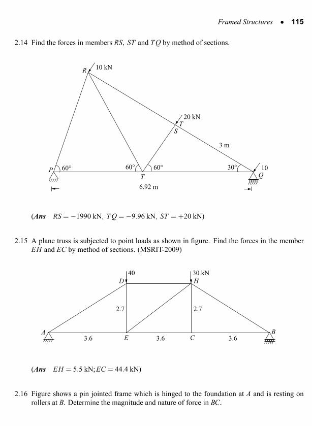
2.14 Find the forces in members RS, ST and T Q by method of sections.
60°60° 60° 30°
10 kN
20 kN
10QT
P
R
ST
6.92 m
3 m
(Ans RS = −1990 kN, T Q = −9.96 kN, ST = +20 kN)
2.15 A plane truss is subjected to point loads as shown in figure. Find the forces in the memberEH and EC by method of sections. (MSRIT-2009)
40
2.7
AE
D H
CB
3.6 3.6 3.6
2.7
30 kN
(Ans EH = 5.5 kN;EC = 44.4 kN)
2.16 Figure shows a pin jointed frame which is hinged to the foundation at A and is resting onrollers at B. Determine the magnitude and nature of force in BC.


![Gioncu [Framed Structures. Ductility and Seismic Response - 2000]](https://static.fdocuments.net/doc/165x107/5532c8424a79599f5e8b4753/gioncu-framed-structures-ductility-and-seismic-response-2000.jpg)