FRAME SIZE AND REDUCTION RATIO - DARALI … · u FRAME SIZE AND REDUCTION RATIO Single reduction...
15
Transcript of FRAME SIZE AND REDUCTION RATIO - DARALI … · u FRAME SIZE AND REDUCTION RATIO Single reduction...
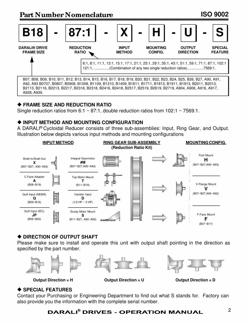
u FRAME SIZE AND REDUCTION RATIOSingle reduction ratios from 6:1 ~ 87:1, double reduction ratios from 102:1 ~ 7569:1.
u INPUT METHOD AND MOUNTING CONFIGURATIONA DARALI® Cycloidal Reducer consists of three sub-assemblies: Input, Ring Gear, and Output.Illustration below depicts various input methods and mounting configurations
u DIRECTION OF OUTPUT SHAFTPlease make sure to install and operate this unit with output shaft pointing in the direction asspecified by the part number.
u SPECIAL FEATURESContact your Purchasing or Engineering Department to find out what S stands for. Factory can
also provide you the information with the complete serial number.
Part Number Nomenclature
B18 87:1 HX U S- - - - -DARALI® DRIVE
FRAME SIZEREDUCTION
RATIOMOUNTING
CONFIG.INPUT
METHODOUTPUT
DIRECTIONSPECIALFEATURE
2
Output Direction = H Output Direction = U Output Direction = D
ISO 9002
6:1, 8:1, 11:1, 13:1, 15:1, 17:1, 21:1, 25:1, 29:1, 35:1, 43:1, 51:1, 59:1, 71:1, 87:1, 102:1
121:1, ...............(Combination of any two single reduction ratios)................7569:1.
B07, B08, B09, B10, B11, B12, B13, B14, B15, B16, B17, B18, B19, B20, B21, B22, B23, B24, B25, B26, B27, A90, A91,A92, A93 B0707, B0807, B0908, B1008, B1109, B1310, B1409, B1611, B1711, B1813, B1911, B1913, B2011, B2013,B2113, B2116, B2213, B2217, B2316, B2318, B2416, B2418, B2517, B2519, B2619, B2719, A904, A906, A916, A917,A928, A939.
MOUNTING CONFIG.RING GEAR SUB-ASSEMBLY(Reduction Ratio Kit)
INPUT METHOD
Shaft-In/Shaft-Out
X(B07~B27, A90~A93)
C-Face Adapter
A(B08~B19)
Quill Input (NEMA)
Q(B09~B16)
Quill Input (IEC)
JP(B09~B20)
Integral Gearmotor
#M(B07~B27,A90~A93)
Foot Mount
H(B07~B27,A90~A93)
V-Flange Mount
V(B07~B27,A90~A92)
F-Face Mount
F(B07~B17)
Top Motor Mount
T(B11~B19)
Variator Input
D(1/2 HP ~ 5 HP)
Scoop Motor Mount
S(B11~B27, A90~A93)
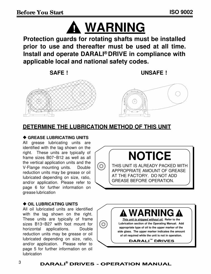
WARNINGProtection guards for rotating shafts must be installedprior to use and thereafter must be used at all time.
Install and operate DARALI® DRIVE in compliance withapplicable local and national safety codes.
NOTICETHIS UNIT IS ALREADY PACKED WITHAPPROPRIATE AMOUNT OF GREASEAT THE FACTORY. DO NOT ADD
GREASE BEFORE OPERATION.
SAFE ! UNSAFE !
u GREASE LUBRICATING UNITSAll grease lubricating units areidentified with the tag shown on theright. These units are typically offrame sizes B07~B12 as well as allthe vertical application units and theV-Flange mounting units. Doublereduction units may be grease or oillubricated depending on size, ratio,and/or application. Please refer topage 6 for further information ongrease lubrication
u OIL LUBRICATING UNITSAll oil lubricated units are identifiedwith the tag shown on the right.
These units are typically of framesizes B13~B27 with foot mount forhorizontal applications. Double
reduction units may be grease or oil
lubricated depending on size, ratio,and/or application. Please refer to
page 5 for further information on oillubrication
DETERMINE THE LUBRICATION METHOD OF THIS UNIT
!
Before You Start ISO 9002
WARNINGThis unit is shipped without oil. Refer to the
Lubrication section of the Operating Manual. Add
appropriate type of oil to the upper marker of the
side glass. The upper marker indicates the amount
of oil required while the unit is not in operation.
! !
3
Daily Inspection ISO 9002
4
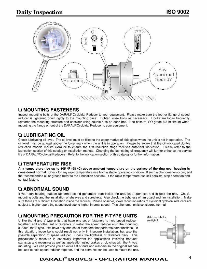
o MOUNTING FASTENERSInspect mounting bolts of the DARALI® Cycloidal Reducer to your equipment. Please make sure the foot or flange of speedreducer is tightened down rigidly to the mounting base. Tighten loose bolts as necessary. If bolts are loose frequently,reinforce the mounting structure and consider using double nuts on each bolt. Use bolts of ISO grade 8.8 minimum whenmounting the flange or feet of the DARALI® Cycloidal Reducer to your equipment.
o LUBRICATING OILCheck lubricating oil level. The oil level must be filled to the upper marker of side glass when the unit is not in operation. Theoil level must be at least above the lower mark when the unit is in operation. Please be aware that the oil-lubricated doublereduction models require extra oil to ensure the first reduction stage receives sufficient lubrication. Please refer to thelubrication section of this catalog or installation manual. Changing the lubricating oil frequently will further enhance the servicelife of DARALI® Cycloidal Reducers. Refer to the lubrication section of this catalog for further information.
o TEMPERATURE RISEAny temperature rise up to 105 oF (58 oC) above ambient temperature on the surface of the ring gear housing isconsidered normal. Check for any rapid temperature rise from a stable operating condition. If such a phenomenon occur, addthe recommended oil or grease (refer to the lubrication section). If the rapid temperature rise still persists, stop operation andcontact factory.
o ABNORMAL SOUNDIf you start hearing sudden abnormal sound generated from inside the unit, stop operation and inspect the unit. Checkmounting bolts and the installation of sheaves and sprockets. Also check the tightness of fan guard and fan installation. Makesure there are sufficient lubrication inside the reducer. Please observe, lower reduction ratios of cycloidal cycloidal reducers aresubject to higher operating sound level due to higher internal speed. This phenomenon is considered normal.
o MOUNTING PRECAUTION FOR THE F-TYPE UNITSUnlike the H and V type units that have one set of fasteners to hold speed reducertogether, and another set of fasteners to install the speed reducer onto the mountingsurface, the F type units have only one set of fasteners that performs both functions. Inthis situation, loose bolts could result not only in insecure installation, but also thepossible separation of speed reducer. Check the tightness of fasteners daily. Thisprecautionary measure is especially important for applications involving frequentstart/stop and reversing as well as application using brakes or clutches with the F-typemounting. We can provide you an extra set of nuts and washers so the original set canbe used to hold speed reducer together, and the extra set can be used to mount the unit.
Make sure bolts
are tight !!
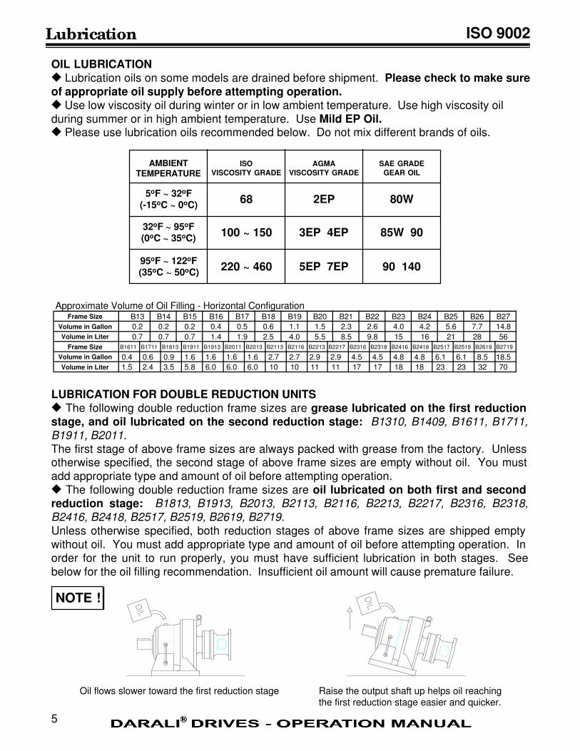
OIL LUBRICATIONu Lubrication oils on some models are drained before shipment. Please check to make sureof appropriate oil supply before attempting operation.u Use low viscosity oil during winter or in low ambient temperature. Use high viscosity oil
during summer or in high ambient temperature. Use Mild EP Oil.u Please use lubrication oils recommended below. Do not mix different brands of oils.
Oil flows slower toward the first reduction stage Raise the output shaft up helps oil reachingthe first reduction stage easier and quicker.
Lubrication
NOTE !
ISO 9002
5
AMBIENTTEMPERATURE
ISO
VISCOSITY GRADE
AGMA
VISCOSITY GRADE
SAE GRADE
GEAR OIL
5oF ~ 32oF(-15oC ~ 0oC)
32oF ~ 95oF(0oC ~ 35oC)
95oF ~ 122oF(35oC ~ 50oC)
68 2EP
100 ~ 150 3EP 4EP
220 ~ 460 5EP 7EP
80W
85W 90
90 140
LUBRICATION FOR DOUBLE REDUCTION UNITSu The following double reduction frame sizes are grease lubricated on the first reductionstage, and oil lubricated on the second reduction stage: B1310, B1409, B1611, B1711,
B1911, B2011.
The first stage of above frame sizes are always packed with grease from the factory. Unlessotherwise specified, the second stage of above frame sizes are empty without oil. You mustadd appropriate type and amount of oil before attempting operation.u The following double reduction frame sizes are oil lubricated on both first and secondreduction stage: B1813, B1913, B2013, B2113, B2116, B2213, B2217, B2316, B2318,
B2416, B2418, B2517, B2519, B2619, B2719.
Unless otherwise specified, both reduction stages of above frame sizes are shipped emptywithout oil. You must add appropriate type and amount of oil before attempting operation. Inorder for the unit to run properly, you must have sufficient lubrication in both stages. See
below for the oil filling recommendation. Insufficient oil amount will cause premature failure.
Approximate Volume of Oil Filling - Horizontal ConfigurationFrame Size B13 B14 B15 B16 B17 B18 B19 B20 B21 B22 B23 B24 B25 B26 B27
Volume in Gallon 0.2 0.2 0.2 0.4 0.5 0.6 1.1 1.5 2.3 2.6 4.0 4.2 5.6 7.7 14.8
Volume in Liter 0.7 0.7 0.7 1.4 1.9 2.5 4.0 5.5 8.5 9.8 15 16 21 28 56
Frame Size B1611 B1711 B1813 B1911 B1913 B2011 B2013 B2113 B2116 B2213 B2217 B2316 B2318 B2416 B2418 B2517 B2519 B2619 B2719
Volume in Gallon 0.4 0.6 0.9 1.6 1.6 1.6 1.6 2.7 2.7 2.9 2.9 4.5 4.5 4.8 4.8 6.1 6.1 8.5 18.5
Volume in Liter 1.5 2.4 3.5 5.8 6.0 6.0 6.0 10 10 11 11 17 17 18 18 23 23 32 70
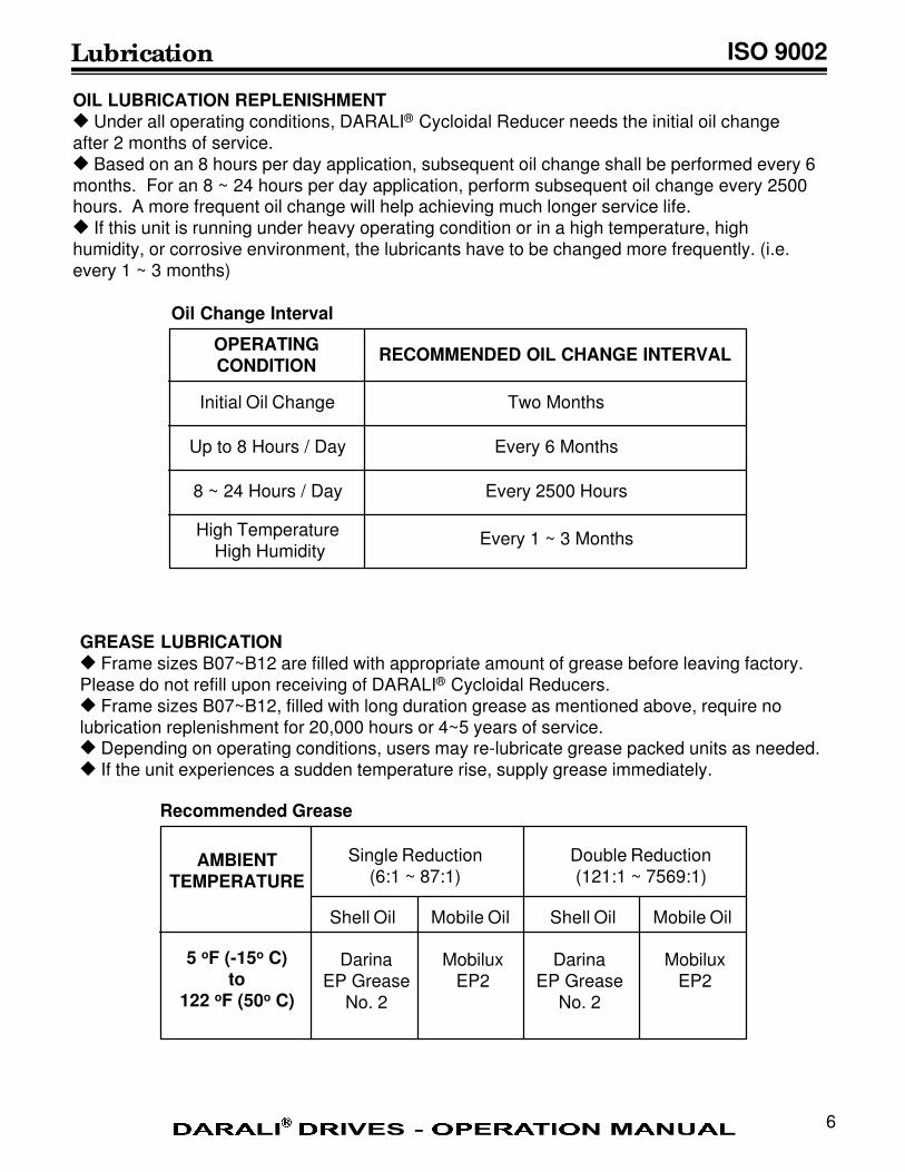
GREASE LUBRICATIONu Frame sizes B07~B12 are filled with appropriate amount of grease before leaving factory.Please do not refill upon receiving of DARALI® Cycloidal Reducers.u Frame sizes B07~B12, filled with long duration grease as mentioned above, require nolubrication replenishment for 20,000 hours or 4~5 years of service.u Depending on operating conditions, users may re-lubricate grease packed units as needed.u If the unit experiences a sudden temperature rise, supply grease immediately.
AMBIENTTEMPERATURE
5 oF (-15o C)to
122 oF (50o C)
Single Reduction(6:1 ~ 87:1)
Double Reduction(121:1 ~ 7569:1)
Shell Oil Shell OilMobile Oil Mobile Oil
DarinaEP Grease
No. 2
DarinaEP Grease
No. 2
MobiluxEP2
MobiluxEP2
Recommended Grease
Lubrication
OIL LUBRICATION REPLENISHMENTu Under all operating conditions, DARALI® Cycloidal Reducer needs the initial oil change
after 2 months of service.
u Based on an 8 hours per day application, subsequent oil change shall be performed every 6
months. For an 8 ~ 24 hours per day application, perform subsequent oil change every 2500hours. A more frequent oil change will help achieving much longer service life.
u If this unit is running under heavy operating condition or in a high temperature, high
humidity, or corrosive environment, the lubricants have to be changed more frequently. (i.e.
every 1 ~ 3 months)
OPERATINGCONDITION
RECOMMENDED OIL CHANGE INTERVAL
Initial Oil Change
Up to 8 Hours / Day
8 ~ 24 Hours / Day
High Temperature High Humidity
Two Months
Every 6 Months
Every 2500 Hours
Every 1 ~ 3 Months
Oil Change Interval
ISO 9002
6
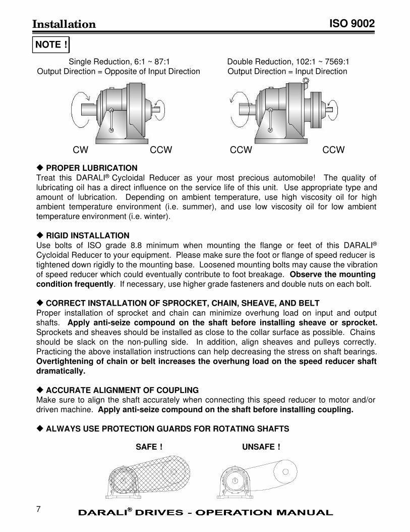
Installation
Single Reduction, 6:1 ~ 87:1
Output Direction = Opposite of Input Direction
Double Reduction, 102:1 ~ 7569:1
Output Direction = Input Direction
u PROPER LUBRICATIONTreat this DARALI® Cycloidal Reducer as your most precious automobile! The quality oflubricating oil has a direct influence on the service life of this unit. Use appropriate type andamount of lubrication. Depending on ambient temperature, use high viscosity oil for highambient temperature environment (i.e. summer), and use low viscosity oil for low ambienttemperature environment (i.e. winter).
u RIGID INSTALLATIONUse bolts of ISO grade 8.8 minimum when mounting the flange or feet of this DARALI®
Cycloidal Reducer to your equipment. Please make sure the foot or flange of speed reducer istightened down rigidly to the mounting base. Loosened mounting bolts may cause the vibrationof speed reducer which could eventually contribute to foot breakage. Observe the mountingcondition frequently. If necessary, use higher grade fasteners and double nuts on each bolt.
u CORRECT INSTALLATION OF SPROCKET, CHAIN, SHEAVE, AND BELTProper installation of sprocket and chain can minimize overhung load on input and outputshafts. Apply anti-seize compound on the shaft before installing sheave or sprocket.Sprockets and sheaves should be installed as close to the collar surface as possible. Chainsshould be slack on the non-pulling side. In addition, align sheaves and pulleys correctly.Practicing the above installation instructions can help decreasing the stress on shaft bearings.
Overtightening of chain or belt increases the overhung load on the speed reducer shaftdramatically.
u ACCURATE ALIGNMENT OF COUPLINGMake sure to align the shaft accurately when connecting this speed reducer to motor and/or
driven machine. Apply anti-seize compound on the shaft before installing coupling.
u ALWAYS USE PROTECTION GUARDS FOR ROTATING SHAFTS
NOTE !
SAFE ! UNSAFE !
ISO 9002
7
CW CCW CCW CCW
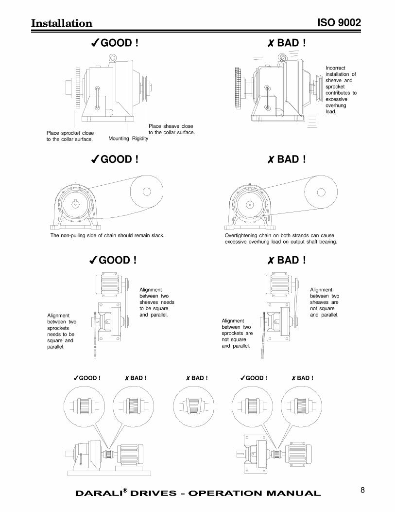
Place sprocket close
to the collar surface. Mounting Rigidity
Place sheave close
to the collar surface.
The non-pulling side of chain should remain slack. Overtightening chain on both strands can cause
excessive overhung load on output shaft bearing.
Alignment
between two
sheaves needs
to be square
and parallel.Alignment
between two
sprockets
needs to be
square and
parallel.
Alignment
between two
sheaves are
not square
and parallel.Alignment
between two
sprockets are
not square
and parallel.
ISO 9002
8
4GOOD ! 8BAD !
8BAD !
4GOOD ! 8BAD !
4GOOD ! 8BAD ! 4GOOD ! 8BAD !8BAD !
4GOOD !
Incorrect
installation of
sheave and
sprocket
contributes to
excessive
overhung
load.
Installation
ISO 9002Parts List - Single Reduction
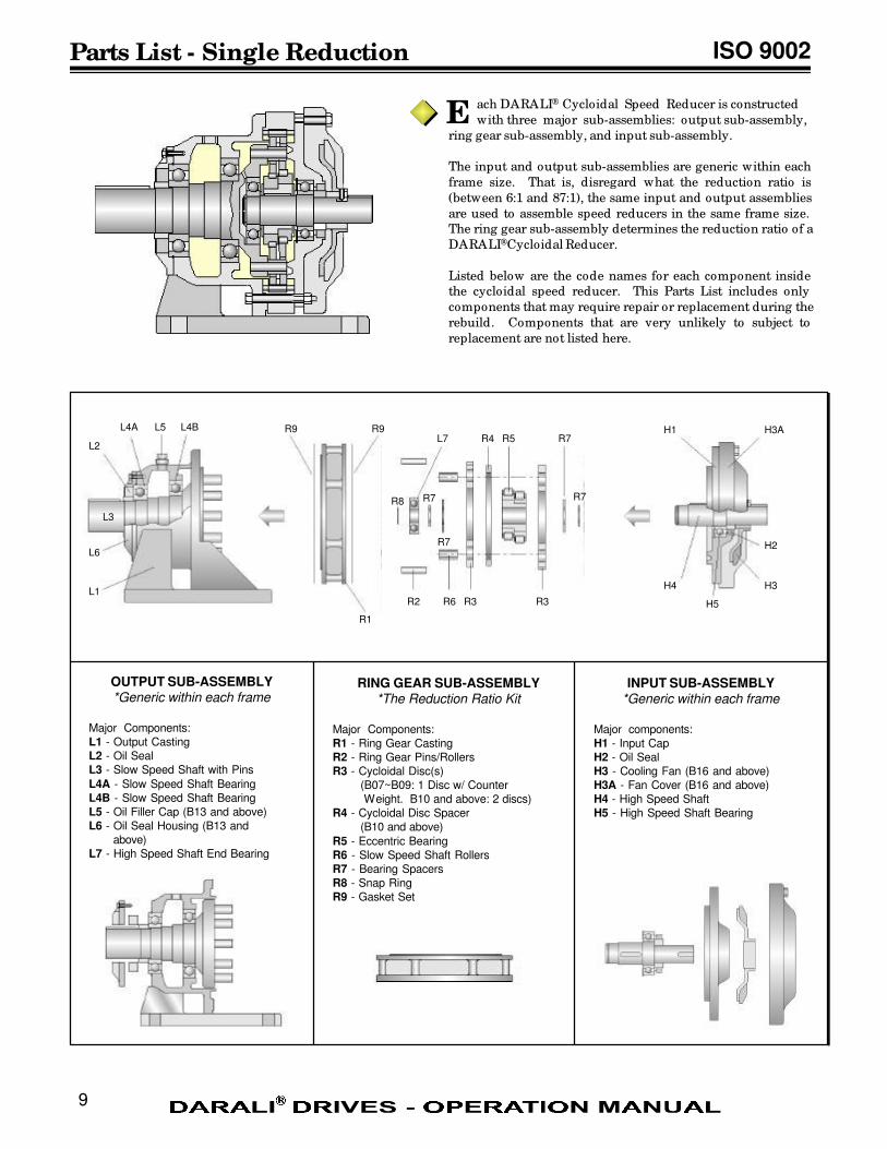
ach DARALI® Cycloidal Speed Reducer is constructed
with three major sub-assemblies: output sub-assembly,
ring gear sub-assembly, and input sub-assembly.
The input and output sub-assemblies are generic within each
frame size. That is, disregard what the reduction ratio is
(between 6:1 and 87:1), the same input and output assemblies
are used to assemble speed reducers in the same frame size.
The ring gear sub-assembly determines the reduction ratio of a
DARALI® Cycloidal Reducer.
Listed below are the code names for each component inside
the cycloidal speed reducer. This Parts List includes only
components that may require repair or replacement during the
rebuild. Components that are very unlikely to subject to
replacement are not listed here.
OUTPUT SUB-ASSEMBLY*Generic within each frame
Major Components:
L1 - Output Casting
L2 - Oil Seal
L3 - Slow Speed Shaft with Pins
L4A - Slow Speed Shaft Bearing
L4B - Slow Speed Shaft Bearing
L5 - Oil Filler Cap (B13 and above)
L6 - Oil Seal Housing (B13 and
above)
L7 - High Speed Shaft End Bearing
INPUT SUB-ASSEMBLY*Generic within each frame
Major components:
H1 - Input Cap
H2 - Oil Seal
H3 - Cooling Fan (B16 and above)
H3A - Fan Cover (B16 and above)
H4 - High Speed Shaft
H5 - High Speed Shaft Bearing
RING GEAR SUB-ASSEMBLY*The Reduction Ratio Kit
Major Components:
R1 - Ring Gear Casting
R2 - Ring Gear Pins/Rollers
R3 - Cycloidal Disc(s)
(B07~B09: 1 Disc w/ Counter
Weight. B10 and above: 2 discs)
R4 - Cycloidal Disc Spacer
(B10 and above)
R5 - Eccentric Bearing
R6 - Slow Speed Shaft Rollers
R7 - Bearing Spacers
R8 - Snap Ring
R9 - Gasket Set
E
L4BL5
R1
R2 R3 R3
R4 R5
R6
L7
R7
R7
R7H1
H2
H3A
H3H4
R8
L2
L3
L1
L6
L4A
R7
H5
R9 R9
9
ISO 9002
10
Parts List - Single Reduction
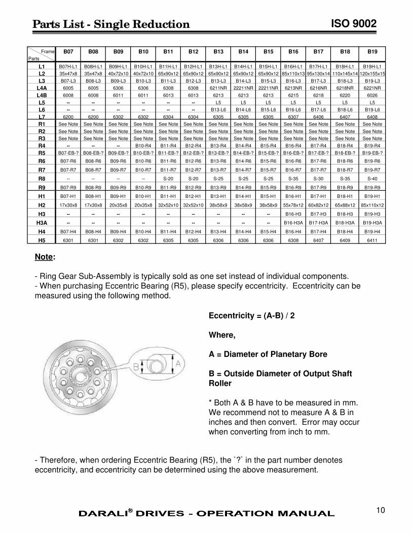
Note:
- Ring Gear Sub-Assembly is typically sold as one set instead of individual components.- When purchasing Eccentric Bearing (R5), please specify eccentricity. Eccentricity can bemeasured using the following method.
- Therefore, when ordering Eccentric Bearing (R5), the “?” in the part number denotes
eccentricity, and eccentricity can be determined using the above measurement.
Eccentricity = (A-B) / 2
Where,
A = Diameter of Planetary Bore
B = Outside Diameter of Output ShaftRoller
* Both A & B have to be measured in mm.We recommend not to measure A & B ininches and then convert. Error may occurwhen converting from inch to mm.
Frame B07 B08 B09 B10 B11 B12 B13 B14 B15 B16 B17 B18 B19
Parts
L1 B07H-L1 B08H-L1 B09H-L1 B10H-L1 B11H-L1 B12H-L1 B13H-L1 B14H-L1 B15H-L1 B16H-L1 B17H-L1 B18H-L1 B19H-L1
L2 35x47x8 35x47x8 40x72x10 40x72x10 65x90x12 65x90x12 65x90x12 65x90x12 65x90x12 85x110x13 95x130x14 110x145x14 120x155x15
L3 B07-L3 B08-L3 B09-L3 B10-L3 B11-L3 B12-L3 B13-L3 B14-L3 B15-L3 B16-L3 B17-L3 B18-L3 B19-L3
L4A 6005 6005 6306 6306 6308 6308 6211NR 22211NR 22211NR 6213NR 6216NR 6218NR 6221NR
L4B 6008 6008 6011 6011 6013 6013 6213 6213 6213 6215 6218 6220 6026
L5 -- -- -- -- -- -- L5 L5 L5 L5 L5 L5 L5
L6 -- -- -- -- -- -- B13-L6 B14-L6 B15-L6 B16-L6 B17-L6 B18-L6 B19-L6
L7 6200 6200 6302 6302 6304 6304 6305 6305 6305 6307 6406 6407 6408
R1 See Note See Note See Note See Note See Note See Note See Note See Note See Note See Note See Note See Note See Note
R2 See Note See Note See Note See Note See Note See Note See Note See Note See Note See Note See Note See Note See Note
R3 See Note See Note See Note See Note See Note See Note See Note See Note See Note See Note See Note See Note See Note
R4 -- -- -- B10-R4 B11-R4 B12-R4 B13-R4 B14-R4 B15-R4 B16-R4 B17-R4 B18-R4 B19-R4
R5 B07-EB-? B08-EB-? B09-EB-? B10-EB-? B11-EB-? B12-EB-? B13-EB-? B14-EB-? B15-EB-? B16-EB-? B17-EB-? B18-EB-? B19-EB-?
R6 B07-R6 B08-R6 B09-R6 B10-R6 B11-R6 B12-R6 B13-R6 B14-R6 B15-R6 B16-R6 B17-R6 B18-R6 B19-R6
R7 B07-R7 B08-R7 B09-R7 B10-R7 B11-R7 B12-R7 B13-R7 B14-R7 B15-R7 B16-R7 B17-R7 B18-R7 B19-R7
R8 -- -- -- -- S-20 S-20 S-25 S-25 S-25 S-35 S-30 S-35 S-40
R9 B07-R9 B08-R9 B09-R9 B10-R9 B11-R9 B12-R9 B13-R9 B14-R9 B15-R9 B16-R9 B17-R9 B18-R9 B19-R9
H1 B07-H1 B08-H1 B09-H1 B10-H1 B11-H1 B12-H1 B13-H1 B14-H1 B15-H1 B16-H1 B17-H1 B18-H1 B19-H1
H2 17x30x8 17x30x8 20x35x8 20x35x8 32x52x10 32x52x10 38x58x9 38x58x9 38x58x9 55x78x12 60x82x12 65x88x12 85x110x12
H3 -- -- -- -- -- -- -- -- -- B16-H3 B17-H3 B18-H3 B19-H3
H3A -- -- -- -- -- -- -- -- -- B16-H3A B17-H3A B18-H3A B19-H3A
H4 B07-H4 B08-H4 B09-H4 B10-H4 B11-H4 B12-H4 B13-H4 B14-H4 B15-H4 B16-H4 B17-H4 B18-H4 B19-H4
H5 6301 6301 6302 6302 6305 6305 6306 6306 6306 6308 6407 6409 6411
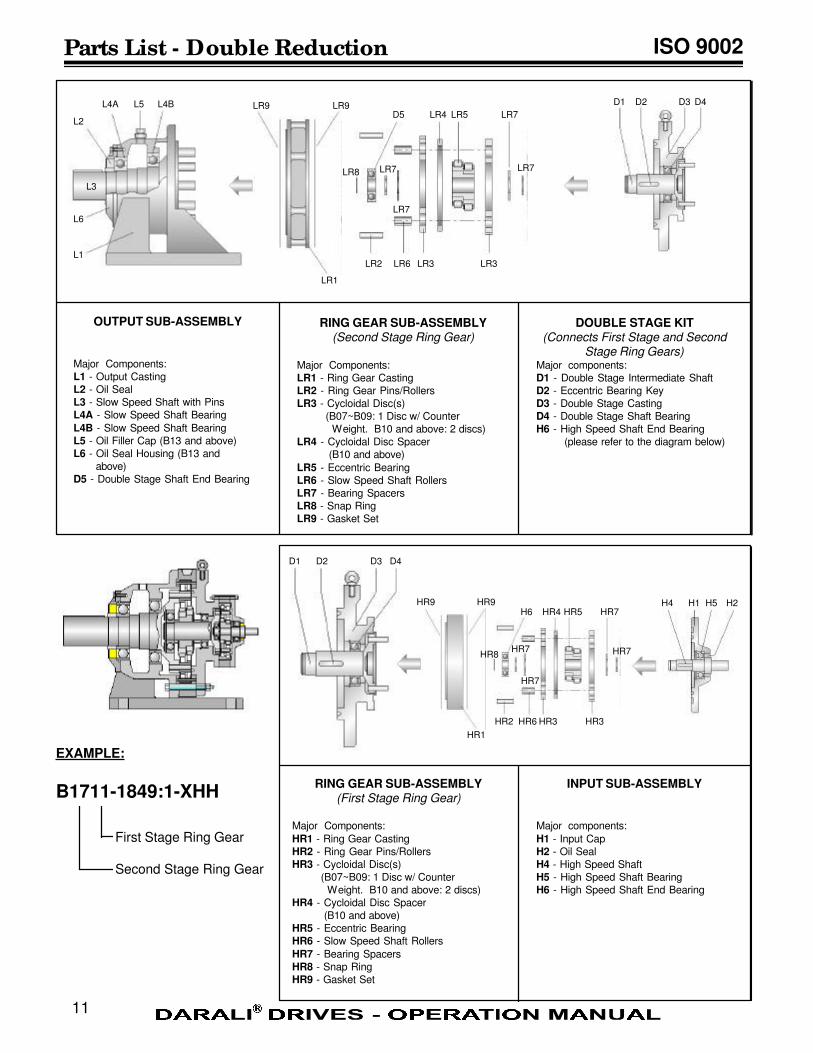
ISO 9002Parts List - Double Reduction
OUTPUT SUB-ASSEMBLY
Major Components:
L1 - Output Casting
L2 - Oil Seal
L3 - Slow Speed Shaft with Pins
L4A - Slow Speed Shaft Bearing
L4B - Slow Speed Shaft Bearing
L5 - Oil Filler Cap (B13 and above)
L6 - Oil Seal Housing (B13 and
above)
D5 - Double Stage Shaft End Bearing
DOUBLE STAGE KIT(Connects First Stage and Second
Stage Ring Gears)Major components:
D1 - Double Stage Intermediate Shaft
D2 - Eccentric Bearing Key
D3 - Double Stage Casting
D4 - Double Stage Shaft Bearing
H6 - High Speed Shaft End Bearing
(please refer to the diagram below)
RING GEAR SUB-ASSEMBLY(Second Stage Ring Gear)
Major Components:
LR1 - Ring Gear Casting
LR2 - Ring Gear Pins/Rollers
LR3 - Cycloidal Disc(s)
(B07~B09: 1 Disc w/ Counter
Weight. B10 and above: 2 discs)
LR4 - Cycloidal Disc Spacer
(B10 and above)
LR5 - Eccentric Bearing
LR6 - Slow Speed Shaft Rollers
LR7 - Bearing Spacers
LR8 - Snap Ring
LR9 - Gasket Set
L4BL5
LR1
LR2 LR3 LR3
LR4 LR5
LR6
D5
LR7
LR7
LR7
LR8
L2
L3
L1
L6
L4A
LR7
LR9 LR9 D1 D2 D3 D4
HR2 HR3 HR3
HR4 HR5
HR6
H6
HR7
HR7
HR7
HR7
HR9 HR9
D1 D2 D3 D4
RING GEAR SUB-ASSEMBLY(First Stage Ring Gear)
Major Components:
HR1 - Ring Gear Casting
HR2 - Ring Gear Pins/Rollers
HR3 - Cycloidal Disc(s)
(B07~B09: 1 Disc w/ Counter
Weight. B10 and above: 2 discs)
HR4 - Cycloidal Disc Spacer
(B10 and above)
HR5 - Eccentric Bearing
HR6 - Slow Speed Shaft Rollers
HR7 - Bearing Spacers
HR8 - Snap Ring
HR9 - Gasket Set
INPUT SUB-ASSEMBLY
Major components:
H1 - Input Cap
H2 - Oil Seal
H4 - High Speed Shaft
H5 - High Speed Shaft Bearing
H6 - High Speed Shaft End Bearing
H1 H2H4 H5
HR1
HR8
EXAMPLE:
B1711-1849:1-XHH
First Stage Ring Gear
Second Stage Ring Gear
11
ISO 9002
12
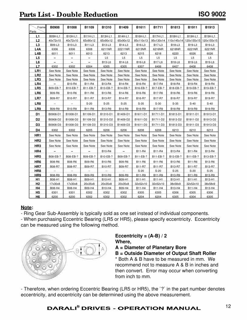
Parts List - Double Reduction
Note:- Ring Gear Sub-Assembly is typically sold as one set instead of individual components.
- When purchasing Eccentric Bearing (LR5 or HR5), please specify eccentricity. Eccentricity
can be measured using the following method.
- Therefore, when ordering Eccentric Bearing (LR5 or HR5), the “?” in the part number denotes
eccentricity, and eccentricity can be determined using the above measurement.
Eccentricity = (A-B) / 2Where,A = Diameter of Planetary BoreB = Outside Diameter of Output Shaft Roller* Both A & B have to be measured in mm. Werecommend not to measure A & B in inches and
then convert. Error may occur when convertingfrom inch to mm.
Frame B0908 B1008 B1109 B1310 B1409 B1611 B1711 B1813 B1911 B1913
Parts
L1 B09H-L1 B10H-L1 B11H-L1 B13H-L1 B14H-L1 B16H-L1 B17H-L1 B18H-L1 B19H-L1 B19H-L1
L2 40x72x10 40x72x10 65x90x12 65x90x12 65x90x12 85x110x13 95x130x14 110x145x14 120x155x15 120x155x15
L3 B09-L3 B10-L3 B11-L3 B13-L3 B14-L3 B16-L3 B17-L3 B18-L3 B19-L3 B19-L3
L4A 6306 6306 6308 6211NR 22211NR 6213NR 6216NR 6218NR 6221NR 6221NR
L4B 6011 6011 6013 6213 6213 6215 6218 6220 6026 6026
L5 -- -- -- L5 L5 L5 L5 L5 L5 L5
L6 -- -- -- B13-L6 B14-L6 B16-L6 B17-L6 B18-L6 B19-L6 B19-L6
L7 6302 6302 6304 6305 6305 6307 6406 6407 6408 6408
LR1 See Note See Note See Note See Note See Note See Note See Note See Note See Note See Note
LR2 See Note See Note See Note See Note See Note See Note See Note See Note See Note See Note
LR3 See Note See Note See Note See Note See Note See Note See Note See Note See Note See Note
LR4 -- B10-R4 B11-R4 B13-R4 B14-R4 B16-R4 B17-R4 B18-R4 B19-R4 B19-R4
LR5 B09-EB-? B10-EB-? B11-EB-? B13-EB-? B14-EB-? B16-EB-? B17-EB-? B18-EB-? B19-EB-? B19-EB-?
LR6 B09-R6 B10-R6 B11-R6 B13-R6 B14-R6 B16-R6 B17-R6 B18-R6 B19-R6 B19-R6
LR7 B09-R7 B10-R7 B11-R7 B13-R7 B14-R7 B16-R7 B17-R7 B18-R7 B19-R7 B19-R7
LR8 -- -- S-20 S-25 S-25 S-35 S-30 S-35 S-40 S-40
LR9 B09-R9 B10-R9 B11-R9 B13-R9 B14-R9 B16-R9 B17-R9 B18-R9 B19-R9 B19-R9
D1 B0908-D1 B1008-D1 B1109-D1 B1310-D1 B1409-D1 B1611-D1 B1711-D1 B1813-D1 B1911-D1 B1913-D1
D2 B0908-D2 B1008-D2 B1109-D2 B1310-D2 B1409-D2 B1611-D2 B1711-D2 B1813-D2 B1911-D2 B1913-D2
D3 B0908-D3 B1008-D3 B1109-D3 B1310-D3 B1409-D3 B1611-D3 B1711-D3 B1813-D3 B1911-D3 B1913-D3
D4 6302 6302 6205 6206 6206 6208 6208 6213 6210 6213
HR1 See Note See Note See Note See Note See Note See Note See Note See Note See Note See Note
HR2 See Note See Note See Note See Note See Note See Note See Note See Note See Note See Note
HR3 See Note See Note See Note See Note See Note See Note See Note See Note See Note See Note
HR4 -- -- -- B10-R4 -- B11-R4 B11-R4 B13-R4 B11-R4 B13-R4
HR5 B08-EB-? B08-EB-? B09-EB-? B10-EB-? B09-EB-? B11-EB-? B11-EB-? B13-EB-? B11-EB-? B13-EB-?
HR6 B08-R6 B08-R6 B09-R6 B10-R6 B09-R6 B11-R6 B11-R6 B13-R6 B11-R6 B13-R6
HR7 B08-R7 B08-R7 B09-R7 B10-R7 B09-R7 B11-R7 B11-R7 B13-R7 B11-R7 B13-R7
HR8 -- -- -- -- -- S-20 S-20 S-25 S-20 S-25
HR9 B08-R9 B08-R9 B09-R9 B10-R9 B09-R9 B11-R9 B11-R9 B13-R9 B11-R9 B13-R9
H1 B08-H1 B08-H1 B09-H1 B10-H1 B09-H1 B11-H1 B11-H1 B13-H1 B11-H1 B13-H1
H2 17x30x8 17x30x8 20x35x8 20x35x8 20x35x8 32x52x10 32x52x10 38x58x9 32x52x10 38x58x9
H4 B08-H4 B08-H4 B09-H4 B10-H4 B09-H4 B11-H4 B11-H4 B13-H4 B11-H4 B13-H4
H5 6301 6301 6302 6302 6302 6305 6305 6306 6305 6306
H6 6200 6200 6302 6302 6302 6204 6204 6305 6304 6305
13
Standard Motor Characteristics ISO 9002
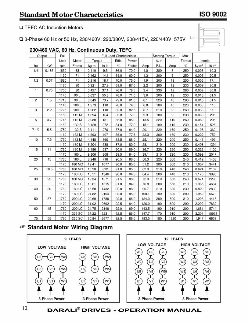
230/460 VAC, 60 Hz, Continuous Duty, TEFC Output Full Full Load Characteristic Starting Torque Max.
Load Motor Torque Effic. Power % of Torque Inertia
hp kW rpm Frame kg-m in-lb % Factor Amp F.L. Amp %
1/4 0.185 1650 63 0.110 9.5 66.0 70.0 1.0 280 6 250 0.003 10.3
1120 71 0.162 14.1 64.0 60.0 1.3 200 6 250 0.006 20.5
1/2 0.37 1680 71 0.216 18.7 70.0 75.0 1.9 200 12 250 0.005 17.1
1130 80 0.321 27.9 68.0 67.0 2.2 200 12 230 0.009 30.8
1 0.75 1700 80 0.427 37.1 76.0 76.5 3.4 230 19 280 0.009 30.8
1140 90 L 0.637 55.3 76.0 71.0 3.6 200 19 230 0.018 61.5
2 1.5 1710 90 L 0.849 73.7 79.0 81.0 6.1 220 40 280 0.018 61.5
1140 100 L 1.273 110 78.0 74.0 6.8 180 40 220 0.033 113
3 2.2 1725 100 L 1.262 110 82.0 82.5 8.7 210 68 260 0.033 113
1150 112 M 1.894 164 82.0 77.0 9.3 180 68 230 0.060 205
5 3.7 1745 112 M 2.080 181 85.0 85.0 13.5 220 110 260 0.060 205
1160 132 S 3.129 272 84.0 77.0 15.1 180 110 230 0.154 526
7 1/2 5.5 1750 132 S 3.111 270 87.0 84.0 20.1 220 160 250 0.106 362
1160 132 M 4.693 407 85.0 77.5 22.3 200 160 230 0.222 759
10 7.5 1750 132 M 4.148 360 88.5 88.0 25.1 220 200 250 0.146 499
1170 160 M 6.204 538 87.0 80.0 28.1 210 200 230 0.408 1394
15 11 1760 160 M 6.186 537 90.0 89.0 36.7 220 290 250 0.322 1100
1170 160 L 9.306 808 89.5 84.0 39.1 210 290 230 0.599 2047
20 15 1760 160 L 8.248 716 90.5 86.0 50.3 220 360 240 0.412 1408
1170 180 MC 12.41 1077 90.0 85.0 51.2 200 360 210 1.007 3441
25 18.5 1765 180 MC 10.28 892 91.0 85.5 62.9 210 440 240 0.624 2132
1170 180 LC 15.51 1346 90.0 84.5 64.4 200 440 210 1.170 3998
30 22 1765 180 MC 12.34 1071 91.5 88.0 72.9 210 550 240 0.671 2293
1170 180 LC 18.61 1615 91.0 84.0 76.8 200 550 210 1.365 4664
40 30 1760 180 LC 16.50 1432 92.0 88.0 96.7 210 620 230 0.829 2833
1170 180 LC 24.82 2154 92.0 85.0 100.1 190 620 200 1.952 6670
50 37 1760 200 LC 20.60 1788 92.0 86.0 124.0 200 800 210 1.293 4418
1170 200 LC 31.02 2692 92.5 84.0 126.0 190 800 200 2.292 7832
60 45 1760 200 LC 24.75 2148 92.0 89.0 143.5 190 910 200 1.681 5744
1170 225 SC 37.22 3231 92.5 86.0 147.7 170 910 200 3.201 10938
75 55 1765 225 SC 30.84 2677 92.5 86.5 183.5 180 1220 200 1.947 6653
+ Standard Motor Wiring Diagram
q TEFC AC Induction Motors
q 3-Phase 60 Hz or 50 Hz, 230/460V, 220/380V, 208/415V, 220/440V, 575V
U1 V1 W1
U5 V5 W5
U2 V2 W2
U1 V1 W1
U5 V5 W5
U2 V2 W2
3-Phase Power 3-Phase Power
LOW VOLTAGE HIGH VOLTAGE
9 LEADS
U1 V1 W1
U5 V5 W5
W2 U2 V2
3-Phase Power 3-Phase Power
LOW VOLTAGE HIGH VOLTAGE
W6 U6 V6
U1 V1 W1
W6 U6 V6
W2 U2 V2
W5 U5 V5
kg-m2 lb-in2
12 LEADS
Brakemotor Wiring Diagram ISO 9002
14
U1 V1 W1
U5 V5 W5
U2 V2 W2
U1 V1 W1
U5 V5 W5
U2 V2 W2
230 VAC, 60 Hz3-Phase
460 VAC, 60 Hz3-Phase
LOW VOLTAGE HIGH VOLTAGE
RECTIFIER
90 VDC, 60 Hzto Brake
RECTIFIER
90 VDC, 60 Hzto Brake
U1 V1 W1
U5 V5 W5
W2 U2 V2
230 VAC, 60 Hz3-Phase
460 VAC, 60 Hz3-Phase
LOW VOLTAGE HIGH VOLTAGE
W6 U6 V6
V1 W1 U1
U6 V6 W6
U2 V2 W2
U5 V5 W5
RECTIFIER
90 VDC, 60 Hzto Brake
RECTIFIER
90 VDC, 60 Hzto Brake
9 LEADS WIRING DIAGRAM
12 LEADS WIRING DIAGRAM
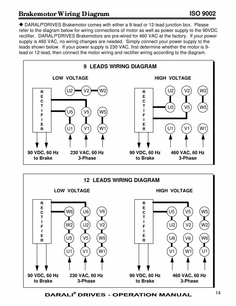
u DARALI® DRIVES Brakemotor comes with either a 9-lead or 12-lead junction box. Please
refer to the diagram below for wiring connections of motor as well as power supply to the 90VDC
rectifier. DARALI® DRIVES Brakemotors are pre-wired for 460 VAC at the factory. If your power
supply is 460 VAC, no wiring changes are needed. Simply connect your power supply to theleads shown below. If your power supply is 230 VAC, first determine whether the motor is 9-
lead or 12-lead, then connect the motor wiring and rectifier wiring according to the diagram.
Manufactured by DARALI GROUP (ISO-9002)
North American Distribution by PTC Endeavor, Inc.
MODEL
INPUT
RATIO
NO.
HP
INCH-LB
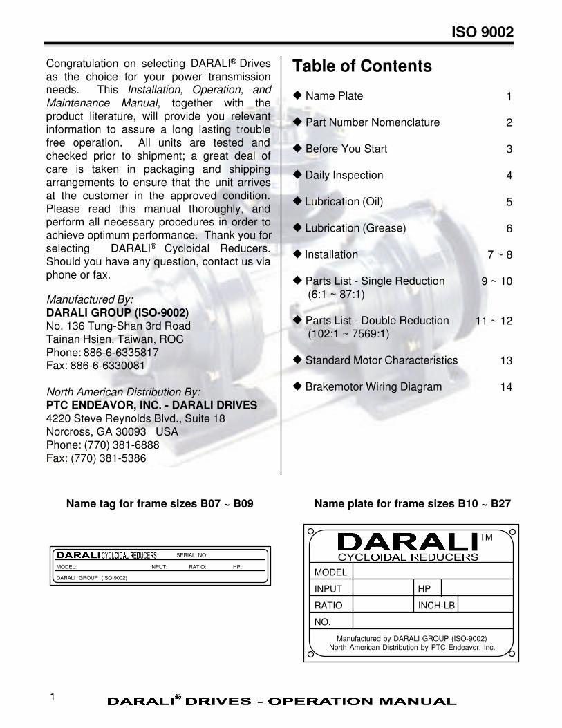
Table of Contents
u Name Plate
u Part Number Nomenclature
u Before You Start
u Daily Inspection
u Lubrication (Oil)
u Lubrication (Grease)
u Installation
u Parts List - Single Reduction (6:1 ~ 87:1)
u Parts List - Double Reduction (102:1 ~ 7569:1)
u Standard Motor Characteristics
u Brakemotor Wiring Diagram
SERIAL NO:
MODEL: INPUT: RATIO: HP:
DARALI GROUP (ISO-9002)
Name tag for frame sizes B07 ~ B09 Name plate for frame sizes B10 ~ B27
1
1
2
3
4
5
6
7 ~ 8
9 ~ 10
11 ~ 12
13
14
Congratulation on selecting DARALI® Drives
as the choice for your power transmissionneeds. This Installation, Operation, and
Maintenance Manual, together with the
product literature, will provide you relevant
information to assure a long lasting trouble
free operation. All units are tested and
checked prior to shipment; a great deal of
care is taken in packaging and shipping
arrangements to ensure that the unit arrives
at the customer in the approved condition.
Please read this manual thoroughly, andperform all necessary procedures in order to
achieve optimum performance. Thank you for
selecting DARALI® Cycloidal Reducers.Should you have any question, contact us via
phone or fax.
Manufactured By:
DARALI GROUP (ISO-9002)
No. 136 Tung-Shan 3rd RoadTainan Hsien, Taiwan, ROCPhone: 886-6-6335817Fax: 886-6-6330081
North American Distribution By:
PTC ENDEAVOR, INC. - DARALI DRIVES
4220 Steve Reynolds Blvd., Suite 18Norcross, GA 30093 USAPhone: (770) 381-6888Fax: (770) 381-5386
ISO 9002