Fracture propagation of CO pipelines 049crack arrestors. Indeed, fracture propagation control has...
10
ENERG Y 115 Abstract USA Robert J Eiber Consultant Inc. Robert J Eiber Consultant Atkins Boreas Andrew Cosham 049 Fracture propagation of CO 2 pipelines The fourth report from the Intergovernmental Panel on Climate Change states that “Warming of the climate system is unequivocal…” It further states that there is a “very high confidence that the global average net effect of human activities since 1750 has been one of warming”. One of the proposed technologies that may play a role in the transition to a low-carbon economy is carbon dioxide capture and storage (CCS). The widespread adoption of CCS will require the transportation of the CO 2 from where it is captured to where it is to be stored. Pipelines can be expected to play a significant role in the required transportation infrastructure. The transportation of CO 2 by long-distance transmission pipeline is an established technology; there are examples of CO 2 pipelines in USA, Europe and Africa. The design and operation of a CO 2 pipeline is more complicated than a typical hydrocarbon pipeline, because of the highly non-linear thermodynamic properties of CO 2 and because it is normally transported in a pipeline as a dense phase fluid. There are number of issues to be considered. Furthermore, CO 2 captured from fossil fuel power stations may contain different proportions and/or types of impurities from those found in the sources of natural or anthropogenic CO 2 transported in the existing CO 2 pipelines. Fracture propagation control is one such issue that requires careful consideration in the design of a CO 2 pipeline. CO 2 pipelines may be more susceptible to long running ductile fractures than hydrocarbon gas pipelines. The need to prevent such propagating fractures imposes either a minimum required toughness (in terms of the Charpy V-notch impact energy) or a requirement for mechanical crack arrestors. Indeed, fracture propagation control has implications for the diameter, wall thickness and grade of the pipeline, in addition to the CVN impact energy of the line pipe steel, because in some situations the requirement for fracture propagation control will dictate the design of a CO 2 pipeline. The issues surrounding fracture propagation control in a CO 2 pipeline are illustrated through the means of two simple design examples: a 24in (609.6mm) diameter pipeline with a design pressure of 100barg, and a 18in (457.2mm) diameter pipeline with a design pressure of 180barg. It has been shown that fracture propagation control in a CO 2 pipeline can be addressed relatively simply. Some care is required because the trends observed in CO 2 pipelines are not the same as those in natural gas pipelines, and the required toughness to arrest a ductile fracture may be very sensitive to small changes in the design parameters. Nevertheless, provided that fracture control is considered early in design, any constraints on the design can be identified and, in principle, resolved without too much difficulty. It is important not to forget that transportation is an implicit, and essential, part of CCS. Introduction The fourth report from the Intergovernmental Panel on Climate Change (IPCC)¹ states that “Warming of the climate system is unequivocal, as is now evident from observations of increases in global average air and ocean temperatures, widespread melting of snow and ice, and rising global average sea level”. It further states that there is “very high confidence that the global average net effect of human activities since 1750 has been one of warming”. Provided that action is taken soon to reduce emissions of ‘greenhouse gases’, the potentially severe effects of climate change can be avoided, without excessive cost 2,3 Carbon dioxide capture and storage (CCS) is one of the technologies that has been proposed to reduce emissions of carbon dioxide (CO 2 ) to the atmosphere from fossil fuel power stations. An IEA (International Energy Agency) study estimated that the widespread adoption of CCS technologies could contribute approximately 20% of the reduction in emissions required to reduce projected emissions in 2050 to their 2003 levels (although, in comparison, energy efficiency measures could contribute approximately 45%) 4 . A second factor that has raised the profile of CCS amongst governments is the need to ensure security of energy supply. Clean-coal technology is seen as having the potential to make a significant proportion of a diverse low-carbon energy mix.
Transcript of Fracture propagation of CO pipelines 049crack arrestors. Indeed, fracture propagation control has...
ENERG
Y
115
Abstract
USA
Robert J Eiber Consultant Inc.
Robert J Eiber
Consultant
Atkins Boreas
Andrew Cosham
049Fracture propagation of CO2 pipelines
The fourth report from the Intergovernmental Panel on Climate Change states that “Warming of the climate system is unequivocal…” It further states that there is a “very high confidence that the global average net effect of human activities since 1750 has been one of warming”. One of the proposed technologies that may play a role in the transition to a low-carbon economy is carbon dioxide capture and storage (CCS). The widespread adoption of CCS will require the transportation of the CO2 from where it is captured to where it is to be stored. Pipelines can be expected to play a significant role in the required transportation infrastructure.
The transportation of CO2 by long-distance transmission pipeline is an established technology; there are examples of CO2 pipelines in USA, Europe and Africa. The design and operation of a CO2 pipeline is more complicated than a typical hydrocarbon pipeline, because of the highly non-linear thermodynamic properties of CO2 and because it is normally transported in a pipeline as a dense phase fluid. There are number of issues to be considered. Furthermore, CO2 captured from fossil fuel power stations may contain different proportions and/or types of impurities from those found in the sources of natural or anthropogenic CO2 transported in the existing CO2 pipelines.
Fracture propagation control is one such issue that requires careful consideration in the design of a CO2 pipeline. CO2 pipelines may be more susceptible to long running ductile fractures than hydrocarbon gas pipelines. The need to prevent such propagating fractures imposes either a minimum required toughness (in terms of the Charpy V-notch impact energy) or a requirement for mechanical crack arrestors. Indeed, fracture propagation control has implications for the diameter, wall thickness and grade of the pipeline, in addition to the CVN impact energy of the line pipe steel, because in some situations the requirement for fracture propagation control will dictate the design of a CO2 pipeline.
The issues surrounding fracture propagation control in a CO2 pipeline are illustrated through the means of two simple design examples: a 24in (609.6mm) diameter pipeline with a design pressure of 100barg, and a 18in (457.2mm) diameter pipeline with a design pressure of 180barg. It has been shown that fracture propagation control in a CO2 pipeline can be addressed relatively simply. Some care is required because the trends observed in CO2
pipelines are not the same as those in natural gas pipelines, and the required toughness to arrest a ductile fracture may be very sensitive to small changes in the design parameters. Nevertheless, provided that fracture control is considered early in design, any constraints on the design can be identified and, in principle, resolved without too much difficulty. It is important not to forget that transportation is an implicit, and essential, part of CCS.
IntroductionThe fourth report from the Intergovernmental Panel on Climate Change (IPCC)¹ states that “Warming of the climate system is unequivocal, as is now evident from observations of increases in global average air and ocean temperatures, widespread melting of snow and ice, and rising global average sea level”. It further states that there is “very high confidence that the global average net effect of human activities since 1750 has been one of warming”.
Provided that action is taken soon to reduce emissions of ‘greenhouse gases’, the potentially severe effects of climate change can be avoided, without excessive cost 2,3
Carbon dioxide capture and storage (CCS) is one of the technologies that has been proposed to reduce emissions of carbon dioxide (CO2) to the atmosphere from fossil fuel power stations. An IEA (International Energy Agency) study estimated that the widespread adoption of CCS technologies could contribute
approximately 20% of the reduction in emissions required to reduce projected emissions in 2050 to their 2003 levels (although, in comparison, energy efficiency measures could contribute approximately 45%)4.
A second factor that has raised the profile of CCS amongst governments is the need to ensure security of energy supply. Clean-coal technology is seen as having the potential to make a significant proportion of a diverse low-carbon energy mix.
ENER
GY
116
049 Fracture propagation of CO2 pipelines
Demonstration Competition now falls under the remit of the Department for Energy and Climate Change (DECC).
The project envisages the construction of 300-400 megawatt plant, capable of capturing up to 90% of its CO2 emissions. A number of countries around the world, including Australia, USA and Norway, also have government supported projects to develop commercial-scale CCS power stations. A 30MW pilot plant at the Schwarze Pumpe power station in Germany, demonstrating carbon capture and storage, opened in September 20085,6.
However, initially the CO2 will be transported to the storage site by road tanker, not pipeline. In simple terms, there are two types of carbon capture technology: pre-combustion and post-combustion, with various methods of implementing either technology. The composition of the ‘captured’ CO2 will depend on the process used to capture it. Once the CO2 is captured it needs to be transported to where it is to be stored. Pipelines can be expected to play a significant role in the required transportation infrastructure7. Transportation is an essential part of carbon capture and storage, but sometimes appears to be something of a Cinderella subject.
The transportation of CO2 by long-distance transmission pipeline is an established technology. The design and operation of a CO2 pipeline is more complicated than a typical hydrocarbon pipeline7,8. One of the issues that needs to be considered is fracture control, and specifically fracture propagation control.
Fracture control is concerned with designing a pipeline with a high tolerance to defects introduced during manufacturing, construction and service; and preventing, or minimising the length of, long running fractures. CO2 pipelines are potentially more susceptible to long running fractures than conventional natural gas pipelines.
Existing CO2 pipelines transport CO2 from CO2 dome fields and plants processing gas from reservoirs with a high proportion of CO2. ‘Captured’ CO2 may have a different composition.
Coal is one of the most available sources of energy in the USA, and similarly in the UK and other parts of Europe, not to mention the rest of the world. A clean-coal power station would incorporate CCS.
The UK government, through the Department for Business, Enterprise & Regulatory Reform (BERR) has organised a competition to develop a commercial-scale coal-fired plant capable of demonstrating the full range of CCS technologies, the CCS
Existing CO2 pipelines New CO2 pipelines
EOR CCS
nearly pure CO2 from dome fields impurities, depending on the capture method
remote, unpopulated areas populated areas
‘static’ demand fluctuation demand (due to load factors)
higher throughput ?
Table 1 - Differences between existing and new CO2 pipelines
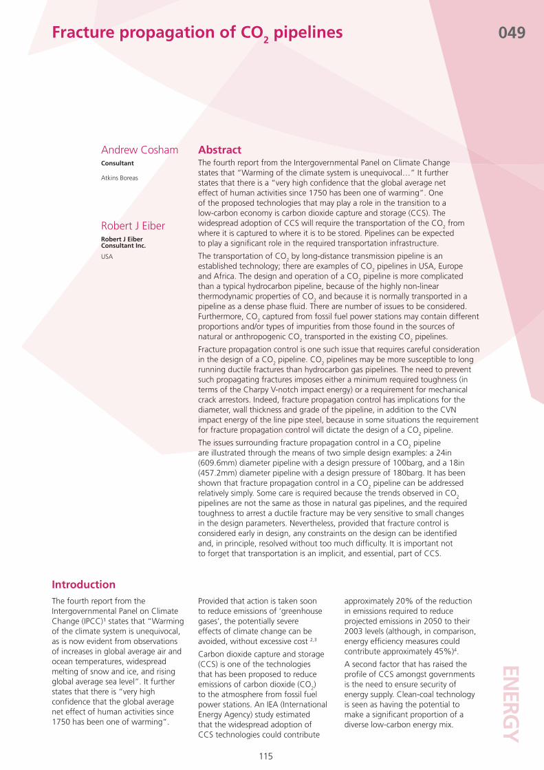
Figure 2 - Experimental and theoretical decompression curves for CO2 (after Maxey (1986))
Figure 1 - Fracture control

ENERG
Y
117
049Fracture propagation of CO2 pipelines
The composition of the CO2, i.e. the type and proportion of the impurities in the CO2, may have a significant effect on the susceptibility of the pipeline to a running fracture, in addition to its effect on hydraulic design9.
In this paper the issues surrounding fracture propagation control in a CO2 pipeline are illustrated through the means of two simple design examples.
Fracture controlFracture control is an important consideration in the design of a pipeline. A fracture control plan for a pipeline will consider two issues see Figure 1:
Fracture initiation control(1)
Fracture propagation control.(2)
A propagating (or running) fracture will result in the loss of many lengths of line pipe, and hence is undesirable.
Fracture propagation control is achieved by ensuring that the toughness of the line pipe steel is sufficiently high to arrest propagating fractures. Fracture propagation control needs to be considered in pipelines conveying gaseous fluids, two phase fluids, dense phase
fluids, or liquids with high vapour pressures. Propagating fractures are described as either brittle or ductile.
Brittle propagating fractures are prevented by ensuring that the line pipe steel is operating on the ‘upper shelf’. Ductile propagating fractures are prevented by specifying a minimum toughness to ensure that a ductile fracture will arrest; or, if the required toughness is too high, by using mechanical crack arrestors.
Line pipe specifications and pipeline design codes specify toughness requirements in terms of the minimum shear area as measured in a Drop Weight Tear Test (DWTT) to address the ‘upper shelf’ requirement10-13. Brittle fracture propagation is not an issue in modern line pipe steel.
A ductile fracture will not propagate if there is insufficient energy in the system to overcome the resistance to propagation. The resistance to a running fracture can be characterised by the Charpy-V notch (CVN) impact energy of the line pipe steel - although the relationship between CVN and fracture resistance becomes non-linear at high impact energies (when the full size impact energy exceeds approximately 100J).
The driving force for a running fracture is the internal pressure. If the fluid in the pipeline decompresses slowly, i.e. high pressures at low decompression wave velocities (as is the case for CO2, see Figure 2), then a higher toughness is required to arrest the running fracture.
The Battelle Two-Curve Model, widely used in fracture control studies, expresses the resistance and driving force in terms of the fracture and gas decompression wave velocities 11,12. For CO2 it can be shown that fracture propagation control can be conservatively simplified to determining the toughness required to ensure that the ‘arrest pressure’ is greater than the ‘saturation pressure’ 14-18. The ‘arrest pressure’ can be determined using part of the TCM. The ‘saturation pressure’ can be determined from a phase diagram (or a gas decompression program), given the initial pressure and temperature.
The transportation of carbon dioxide by pipelineCO2 is transported in pipelines over long distances as a dense phase fluid, for operational and economic reasons. The typical range of operating pressures and temperatures of CO2 pipelines are: 1,250psig (86.2barg) to 2,220psig (153barg), 40°F (4°C) to 100°F (38°C)8,19.
CO2 pipelines are susceptible to propagating ductile fractures because the CO2 is transported in the dense phase. It is a high vapour pressure liquid. At high pressures, supercritical CO2 behaves as a liquid, and has a liquid-like density, but it yields a very large volume of gas when its pressure is lowered20.
Fracture propagation control requires careful consideration in the design of a CO2 pipeline, along with a number of other issues such as hydraulics and corrosion control8.
The transportation of CO2 by long distance transmission pipeline is an established technology. The Canyon Reef Carriers pipeline system in West Texas was commissioned in 19727. There are over 2,500km of CO2 pipelines in the USA and Canada for enhanced oil recovery (EOR) projects7, with other pipelines in the Netherlands, Turkey, North
25
50
75
100
125
0 100 200 300 400 500 600velocity (m.s-1)
pres
sure
(bar
g)
CO2 & N2
90
Figure 3 - Theoretical decompression curves for mixtures of CO2 & N2

ENER
GY
118
049
The decompression path then crosses the phase boundary, and the now two phase fluid decompresses much more slowly. Experimentally determined decompression curves for CO2 are illustrated in Figure 2. The discontinuity in the decompression curve occurs when the decompression path crosses the phase boundary; the pressure at which it crosses the phase boundary is the saturation pressure.
The decompression in a pipeline following a rupture can be approximated as an isentropic process. GASDECOM is a program for calculating the decompression curve for mixtures of hydrocarbons 11,12. It is based on the Benedict-Webb-Rubin-Starling (BWRS) equation of state, with modified constants known to give accurate estimates of isentropic decompression behaviour. Figure 2 compares the measured decompression curves with theoretical predictions using a modified version of GASDECOM. The agreement between the experimental and theoretical decompression curves is relatively good. Consequently, a reasonable estimate of the saturation pressure, for given initial conditions, can be obtained assuming an isentropic decompression and a phase boundary described by the BWRS equation of state.
The saturation pressure is key to determining the toughness required to arrest a propagating ductile fracture in a CO2 pipeline. Factors that increase the saturation pressure will increase the arrest toughness.
The presence of impurities has a significant effect on the saturation pressure. Impurities such as hydrogen, nitrogen and methane will increase the saturation pressure18. Theoretical decompression curves for mixtures of CO2 and N2, from 0% N2 to 10% N2, are shown in Figure 318, illustrating the significant increase in the saturation pressure as the proportion of N2 increases. This increase in the saturation pressure will significantly increase the arrest toughness (as discussed further in the example below).
The initial pressure and temperature of the fluid also have a significant effect on the saturation pressure. Theoretical predictions of the saturation pressure for 100% CO2, and 99% CO2 and N2, for a range
Africa and Norway (the latter, the Snøhvit pipeline, being the world’s first offshore CO2 pipeline21). The source of the CO2 transported in these pipelines is either natural or anthropogenic (i.e. man-made), although none of the anthropogenic sources are (yet) ‘captured’ CO2 from fossil fuel power stations.
In a wider context, it is also worth noting that there are differences between the existing CO2 pipelines, which were (with the odd exception) constructed for the purposes of EOR, and the new CO2 pipelines that will be constructed as part of the required transportation infrastructure for CCS. Some of these differences are summarised in Table 1. The implications arising from these differences will need to be addressed.
The fact that long distance, high-pressure CO2 pipelines have been designed, constructed and operated successfully for many years indicates that the issues associated with the design and operation of CO2 pipelines can be addressed.
Several CO2 pipelines in USA have mechanical crack arrestors installed at regular intervals along their length, because line pipe with a sufficiently high toughness was not available when the pipelines were constructed7,8,22,23. Fitting crack arrestors is expensive; retro-fitting them to existing pipelines is even more so.
The renewed interest in CO2 pipelines, both new and the change of use of existing pipelines from their current service to CO2 service, means that it is informative to look again at the issue of fracture propagation control in CO2 pipelines.
The decompression characteristics of carbon dioxide and its implications for fracture controlCO2 exhibits highly non-linear thermodynamic properties, and it departs significantly from ideal gas behaviour as the pressure increases. The critical point of CO2 is at a pressure of 73.77bar (1,070psi) and a temperature of 31°C (88°F). The presence of impurities, such as methane or hydrogen, can have a significant effect on the behaviour of the fluid9,18.
The decompression characteristics of a fluid have a significant effect on the toughness required to arrest a running ductile fracture. It is the decompression characteristics of CO2 that mean that fracture propagation control requires careful consideration.
CO2 is normally transported as a dense phase fluid. Consider a rupture in a CO2 pipeline. The CO2 initially decompresses rapidly as a liquid.
Fracture propagation of CO2 pipelines
Figure 4 - The effect of initial conditions on the saturation pressure of a mixture of CO2 & N2
ENERG
Y
119
049
of initial pressures and temperatures are shown in Figure 418. Considering the typical operating pressure and temperature range of CO2 pipelines, increasing the initial temperature and/or decreasing the initial pressure will increase the saturation pressure.
Considering the above, it is clear that the composition of ‘captured’ CO2 and the pipeline operating conditions need to be well defined at the early stages of the design, so that the implications for achieving fracture propagation control can be addressed.
An exampleThe issues associated with achieving fracture propagation control in a CO2 pipeline are illustrated through two examples:
24in (609.6mm) diameter pipeline • with a design pressure of 100barg
18in (457.2mm) diameter pipeline • with a design pressure of 180barg.
The above pipeline diameters and design pressures are representative of what might be required to transport the CO2 produced by a 1,600MW coal fired power station over a distance of approximately 200km. A power station of this size would produce something of the order of 8million tonnes per year of CO2.
In both cases, the line pipe grade is taken to be API 5L X65 and the design factor is 0.72. The wall thicknesses are calculated accordingly. The wall thicknesses of the 24in and 18in diameter pipelines are 9.45mm and 12.76mm, respectively (giving diameter to wall thickness ratios of 64.5 and 35.8, respectively).
In practice, a standard API 5L wall thickness would be adopted and depending upon the pipeline design code (e.g. PD 8010-1,2 : 2004 or ASME B31.424,25,26) wall thickness manufacturing tolerances may also need to be considered. In addition, the design factor may not dictate the minimum required wall thickness (e.g. resistance to external interference in onshore pipelines, collapse and stability in offshore pipelines). For simplicity, none of these issues is considered here. The implication of these issues is that the wall thickness will tend to be slightly (or significantly) greater than the minimum required to satisfy the limit on the design factor.
An increase in the wall thickness is beneficial from a fracture control perspective because it reduces the arrest toughness (see below).
It is assumed that the line pipe steel is operating on the upper shelf, i.e. 85% shear area in a DWTT at the minimum pipeline operating temperature .
It is assumed that the pipelines are onshore, although this has little significance for the purposes of these examples. In some design codes and standards the requirements is expressed in terms of the minimum design temperature, and in others in terms of the minimum operating temperature. In most cases the difference is not significant. It is more conservative to use the minimum design temperature.
All references to Charpy V-notch (CVN) impact energy in the following refer to upper shelf values (i.e. 100% shear) measured using full size (1/1) specimens tested at the minimum pipeline operating temperature. In a line pipe specification, the required impact energy may be expressed as the minimum of three test results or the average of three. The implications of this issue are not considered here.
A Methane (natural gas) Pipeline
Firstly, it is instructive to consider the requirements for fracture propagation control if the above two pipelines were transporting methane (CH4).
There are a number of different methods that could be used to estimate the required Charpy V-notch impact energy to arrest a running ductile fracture (i.e. the arrest toughness). The EPRG Recommendation for crack arrest toughness for high strength line pipe steels13 would be the simplest approach. The Battelle Short Formula (SF)11,12, as recommended in ASME B31.827, is slightly more complicated.
Fracture propagation of CO2 pipelines
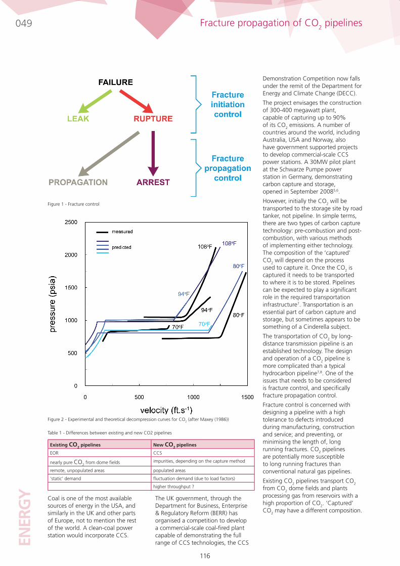
Figure 5 - Theoretical decompression curves for pure CO2 and pure CH4, and fracture velocity curves for the 18 and 24in pipelines
24 in, 100barg 18 in, 180barg
EPRG 40 J 40 J
SF 53 J 53 J
TCM 50 J 40 J
Table 2 - Required full size CVN impact energy for a CH4 pipeline
ENER
GY
120
049
The most accurate, but also the most complicated approach, would be the Battelle Two Curve Model (TCM)11,12. It is important to emphasise that the TCM would not normally be used for a CH4 pipeline (and, in any case, the SF is an approximation to the TCM). It is considered here because its use illustrates the implications of the different decompression curves for CH4 and CO2.
Table 2 gives the required toughness for the two pipelines calculated using the EPRG recommendations, the SF and the TCM. The SF is conservative with respect to the TCM, as would be expected. The EPRG recommendations give the lowest required toughness. The EPRG recommendations for X70 and below are based on 0.75 times the AISI formula, and take into account the statistical distribution of the CVN impact energy in an actual line pipe supply (mid-1990s data).
The minimum toughness specified by the EPRG recommendations ensures that 50% of the line pipe will meet the required toughness. The SF and TCM are simply formulae for calculating the arrest toughness. The results of the three different criteria are broadly comparable. Modern line pipe would easily exceed the required toughness.
Further insight into the underlying behaviour is given in the results of the TCM. Figure 5 shows the theoretical decompression curves for pure methane, based on an initial temperature of 10°C and initial pressures of 100 and 180barg, and the fracture velocity curves for the 18in and 24in diameter pipelines, based on the minimum arrest toughness (and hence the respective decompression and fracture velocity curves intersect at a tangent). The decompression curves are characteristic of the decompression of a gaseous fluid in the gaseous phase. The decompression curve for an initial pressure of 180barg is more severe than that for an initial pressure of 100barg (at any given decompression wave velocity, the decompression pressure is higher). All other factors being equal, increasing the initial pressure increases the arrest toughness. The decompression curve is only part of the picture; it depends only on the initial pressure and temperature and the fluid composition. The fracture velocity curves illustrate the effect of pipeline geometry and grade. The 18in diameter pipeline has a higher resistance to a ductile fracture than the 24in pipeline because the diameter to wall thickness ratio is smaller (for the same toughness, at any given fracture velocity, the required driving pressure is higher) The smaller diameter to wall thickness ratio has a second effect. At any given decompression wave velocity, the hoop stress in the 18in pipeline is lower than that in the 24in pipeline, even though the pressure is higher.
The higher fracture resistance of the 18 in. pipeline more than offsets the higher driving force implied by the decompression curve. Consequently, a lower arrest toughness is predicted for the 18in180 barg pipeline than the 24in 100 barg pipeline.
Fracture propagation of CO2 pipelines
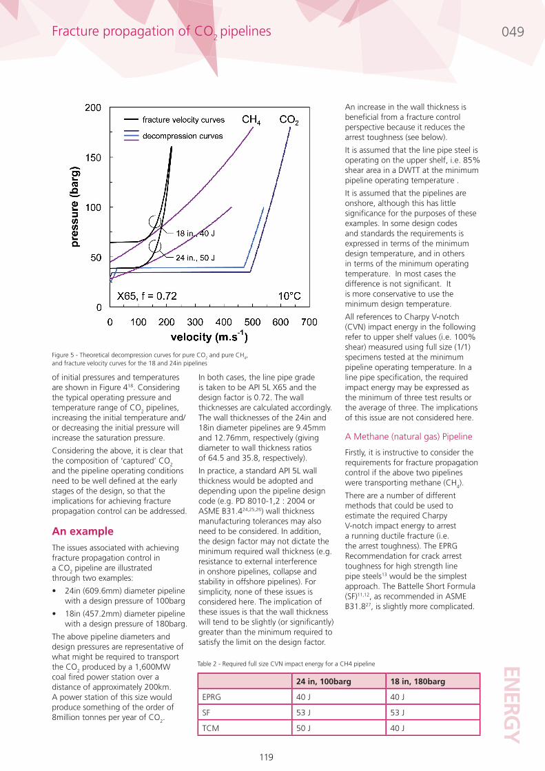
Figure 6 - Isentropic decompression paths
Figure 7 - Effect of saturation pressure on the CVN impact energy required to achieve fracture propagation control in the 18in and 24in pipelines
ENERG
Y
121
049
The following general trends for a CH4 pipeline can be identified:
The higher the initial • pressure, the more severe is the decompression curve
The lower the initial • temperature, the more severe is the decompression curve
The smaller the diameter to • wall thickness ratio, the lower is the arrest toughness
The lower the design factor, the • lower is the arrest toughness.
A Carbon Dioxide Pipeline
Consider now the same 18in and 24in diameter pipelines, but transporting carbon dioxide (CO2) rather than methane.
Figure 5 shows the theoretical decompression curves for pure carbon dioxide, based on an initial temperature of 10°C and initial pressures of 100 and 180barg. The decompression curves are very different from those of methane decompressing from the same initial conditions.
The decompression curves are characteristic of the decompression of a dense phase fluid. The discontinuity, or plateau, in the decompression curve occurs when the decompression path crosses from the single phase region (liquid) into the two phase region (liquid-gas). The marked difference between the decompression curves for methane and carbon dioxide illustrated in Figure 5, clearly demonstrates why it is only necessary to consider the saturation pressure when determining the required arrest toughness in a CO2 pipeline. The full decompression curve is not required. The isentropic decompression paths corresponding to the decompression curves are shown in Figure 6. The saturation pressure is the pressure at which the decompression path intersects the phase boundary. The saturation pressure for an initial pressure of 180barg is lower than that for an initial pressure of 100barg (the estimated saturation pressures are approximately 35barg and 39barg, respectively).
The decompression curve for an initial pressure of 180barg is less severe than that for an initial pressure of 100barg - the opposite of what was observed above.
In the case of a CO2 pipeline, the toughness required to arrest a running ductile fracture can be estimated though consideration of the arrest pressure and the saturation pressure (as previously discussed). The saturation pressure follows from the isentropic decompression path, as indicated in Figure 6. The calculation of the saturation pressure is simpler than the calculation of the decompression curve, and similarly the calculation of the arrest pressure is simpler than the calculation of the fracture velocity curve17.
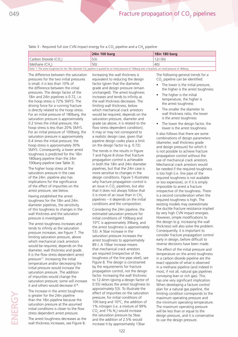
Table 3 gives the required toughness for the two pipelines calculated in this manner (the TCM would give identical results). Comparing the results for a CO2 and a CH4 pipeline, the arrest toughness in the 24in pipeline is slightly higher (although not significantly) when the contents are CO2, and higher in the 18in pipeline when the contents are CH4. The differences in the arrest toughness follows from the decompression characteristics of the two fluids. The results for the 18in pipeline are, in fact, somewhat artificial because it is likely that there would be insufficient energy in the system to sustain a running fracture at the saturation pressure, because the hoop stress is low (the hoop stress at the saturation pressure is less than 20% SMYS). It is important to note that the arrest toughness for the 18in pipeline is not determined by the design pressure; in Table 3 it is assumed that the minimum operating pressure is 100barg, and it is this minimum pressure that determines the required toughness (see below).
For CH4, the higher initial pressure results in a more severe decompression curve. Conversely, for CO2 pipeline, it is the lower initial pressure.
From this observation, it follows that fracture propagation control is easier to achieve in a CO2 pipeline that has a high design pressure. This is illustrated in the decompression paths given in Figure 6.
Fracture propagation of CO2 pipelines
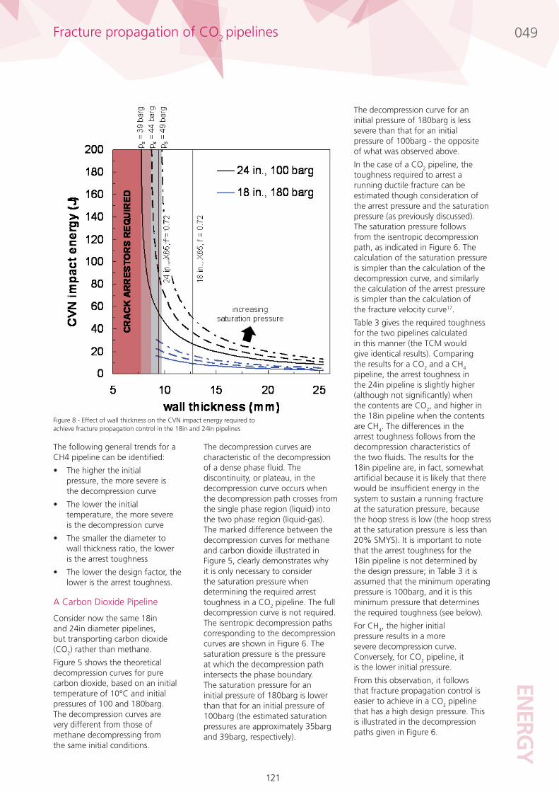
Figure 8 - Effect of wall thickness on the CVN impact energy required to achieve fracture propagation control in the 18in and 24in pipelines
122
049EN
ERG
Y
The following general trends for a CO2 pipeline can be identified:
The lower is the initial pressure, • the higher is the arrest toughness
The higher is the initial • temperature, the higher is the arrest toughness
The smaller the diameter to • wall thickness ratio, the lower is the arrest toughness
The lower the design factor, the • lower is the arrest toughness.
It also follows that there are some combinations of design parameters (diameter, wall thickness grade and design pressure) for which it is not possible to achieve fracture propagation control without the use of mechanical crack arrestors. Mechanical crack arrestors would be needed if the required toughness is too high (i.e. line pipe of the required toughness is not available or too expensive), or if it is simply impossible to arrest a fracture irrespective of the toughness. There is a second consideration when the required toughness is high. The existing models may overestimate the ductile fracture resistance implied by very high CVN impact energies. However, simple modifications to the design (e.g. increasing the wall thickness) will also solve the problem. Consequently, it is important to consider fracture propagation control early in design, before difficult to reverse decisions have been made.
The effect of the initial pressure and temperature on the arrest toughness in a carbon dioxide pipeline are the exact opposite of what is observed in a methane pipeline (and indeed in most, if not all, natural gas pipelines conveying lean or rich gas). This has one very significant implication. When developing a facture control plan for a natural gas pipeline, the limiting condition corresponds to the maximum operating pressure and the minimum operating temperature. The maximum operating pressure will be less than or equal to the design pressure, and it is conservative to use the design pressure.
The difference between the saturation pressures for the two initial pressures is small; it is less than 10% of the difference between the initial pressures. The design factor of the 18in and 24in pipelines is 0.72, i.e. the hoop stress is 72% SMYS. The driving force for a running fracture is directly related to the hoop stress. For an initial pressure of 180barg, the saturation pressure is approximately 0.2 times the initial pressure; the hoop stress is less than 20% SMYS. For an initial pressure of 100barg, the saturation pressure is approximately 0.4 times the initial pressure; the hoop stress is approximately 30% SMYS. Consequently, a lower arrest toughness is predicted for the 18in 180barg pipeline than the 24in 100barg pipeline (see Table 3).
The higher hoop stress at the saturation pressure in the case of the 24in. pipeline also has implications for the significance of the effect of impurities on the arrest pressure, see below.
Having established the arrest toughness for the 18in and 24in. diameter pipelines, the sensitivity of this toughness to changes in the wall thickness and the saturation pressure is investigated.
The arrest toughness increases and tends to infinity as the saturation pressure increases, see Figure 7. The limiting saturation pressure, above which mechanical crack arrestors would be required, depends on the diameter, wall thickness and grade. It is the flow stress dependent arrest pressure17. Increasing the initial temperature and/or decreasing the initial pressure would increase the saturation pressure. The addition of impurities would change the saturation pressure; some will increase it and others would decrease it18.
The increase in the arrest toughness is greater for the 24in pipeline than the 18in pipeline because the saturation pressure at the assumed initial conditions is closer to the flow stress dependent arrest pressure.
The arrest toughness decreases as the wall thickness increases, see Figure 8.
Increasing the wall thickness is equivalent to reducing the design factor (given that the diameter, grade and design pressure remain unchanged). The arrest toughness increases and tends to infinity as the wall thickness decreases. The limiting wall thickness, below which mechanical crack arrestors would be required, depends on the saturation pressure, diameter and grade (as above, it is related to the flow stress dependent condition). It may or may not correspond to a realistic design case, given that pipeline design codes place a limit on the design factor (e.g. 0.72).
The trends in the results in Figure 7 and Figure 8 show that fracture propagation control is achievable in both the 18in and 24in diameter pipelines, but that the 24in case is more sensitive to changes in the design conditions. Figure 5 illustrates why fracture propagation control is an issue in CO2 pipelines, but also that it does not always follow that it is more of an issue than in CH4 pipelines – it depends on the initial conditions and the composition.
Considering the 24in pipeline, the estimated saturation pressure for initial conditions of 100barg and 10°C is approximately 39barg, and the arrest toughness is approximately 53J. A 5bar increase in the saturation pressure increases the arrest toughness to approximately 89 J. A 10bar increase means that mechanical crack arrestors are required (irrespective of the toughness of the line pipe steel), see Figure 8. The design is constrained by the requirements for fracture propagation control, not the design factor. Increasing the wall thickness to 12.4mm (giving a design factor of 0.55) reduces the arrest toughness to approximately 53J. To illustrate the effect of impurities on the saturation pressure, for initial conditions of 100 barg and 10°C, the addition of 1% nitrogen (i.e. a mixture of 99% CO2 and 1% N2) would increase the saturation pressure by 5bar, and the addition of 2.5% would increase it by approximately 13bar.
24in 100 barg 18in 180 bargCarbon Dioxide (CO2) 53J 12J (9J)Methane (CH4) 50J 40JNote: 1. The arrest toughness for the 18in diameter CO2 pipeline is quoted for an initial pressure of 100barg and, in brackets, an initial pressure of 180barg.
Fracture propagation of CO2 pipelines
Table 3 - Required full size CVN impact energy for a CO2 pipeline and a CH4 pipeline
123
049EN
ERGY
In other words, the limiting condition is well defined. This is not the case for a carbon dioxide pipeline. When developing a facture control plan for a carbon dioxide pipeline, the limiting condition corresponds to the minimum operating pressure and the maximum operating temperature.
The minimum operating pressure may not be well defined. It is also a conceptual issue because in design it is normally the maximum pressure that defines the worst case.
Through the examples of the 18in 180barg and 24in 100barg pipelines it has been shown that fracture propagation control in a CO2 pipeline can be addressed relatively simply. There are significant differences between CO2 and CH4 pipelines that mean that fracture propagation control is more of an issue in a CO2 pipeline, but it does not always follow that the arrest toughness will be higher in the CO2 pipeline than for an equivalent CH4 pipeline.
The issue of fracture propagation in CO2 pipelines tends to favour pipelines with a small diameter to wall thickness ratio and large wall thickness (the two are related), low grade, low design factor and a high design pressure, or some combination thereof. The availability of modern, high toughness line pipe steel reduces the significance of some of these trends.
The information required to assess the significance of fracture propagation control will be available at the conceptual stage of design (e.g. pipeline diameter, operating conditions and composition). The calculations are relatively straightforward.
Therefore, it will be simple to define a design envelope in which fracture propagation control can be achieved without the use of mechanical crack arrestors, or, conversely, identify this as an issue early in design. This would be useful in defining the specification for the CO2, e.g. is it necessary to remove impurities (and if so, to what level) when the CO2 is captured.
There are a number of underlying issues that have not been considered in detail here, e.g. the range of applicability of the underlying models, the effect of impurities that might be found in ‘typical’ captured CO2, and experimental validation of the methods, but the principles have been demonstrated.
Fracture propagation of CO2 pipelines
References BERNSTEIN,L. et al, Climate Change 2007: Synthesis Report Summary for Policymakers, 1. An Assessment of the Intergovernmental Panel on Climate Change, Fourth Assessment Report, Intergovernmental Panel on Climate Change, November 2007.
BARKER,T. et al.; Summary for Policy Makers, Working Group III contribution to the Intergovernmental 2. Panel on Climate Change Fourth Assessment Report Climate Change 2007: Mitigation of Climate Change, IPCC WG III 4AR, Intergovernmental Panel on Climate Change, May 2007.
STERN,N.; The Economics of Climate Change: The Stern Review, Cambridge University 3. Press, Cambridge, 2007. (also HM Treasury, 2006 www.hm-treasury.gov.uk)
PHILIBERT,C.; Technology Penetration and Capital Stock Turnover: Lessons from 4. IEA Scenario Analysis, International Energy Agency, Organisation for Economic Co-operation and Development, COM/ENV/EPOC/IEA/SLT(2007)4, May 2007.
HARRABIN,R.; Germany leads 'clean coal' pilot, BBC, 3 September 2008. 5. news.bbc.co.uk/1/hi/sci/tech/7584151.stmwww.vattenfall.com/www/co2_en/co2_en/index.jsp
Conclusions Fracture propagation control (1) is an issue for a CO2 pipeline, but it is readily addressed using the methods that the pipeline industry has developed over the years. Some care is required because the trends observed in CO2 pipelines are not the same as those in natural gas pipelines, and the required toughness to arrest a ductile fracture may be very sensitive to small changes in the design parameters (e.g. pipeline geometry or fluid composition). Nevertheless, provided that fracture control is considered early in design, any constraints on the design can be identified and, in principle, resolved without too much difficulty.
Fracture propagation control in (2) a CO2 pipeline can be achieved through consideration of the arrest pressure and the saturation pressure. The required calculations are therefore much simpler than those required for the Two Curve Model.
Impurities such as methane, (3) nitrogen and hydrogen, will increase the saturation pressure and hence the toughness required to arrest a ductile fracture.
The limiting case for fracture (4) propagation control in a CO2 pipeline is the lowest pressure and highest temperature within the operating envelope.
In some situations, the (5) requirement for fracture propagation control will dictate the design of a CO2 pipeline.
ENER
GY
124
049
DOCTOR,R., PALMER,A., COLEMAN,D., DAVISON,J., HENDRIKS,C., KAARSTAD,O., OZAKI,M. and AUSTELL,M.; 6. Chapter 4 Transport of CO2, IPCC Special Report on Carbon Dioxide Capture and Storage, R. Pichs-Madruga, S. Timashev, Eds., Intergovernmental Panel on Climate Change, Cambridge University Press, Cambridge, 2005.
MOHITPOUR,M., GOLSHAN,H., MURRAY,A.; Pipeline Design and Construction, 7. A Practical Approach, ASME Press, New York, 2000.
SEEVAM,P.N., RACE,J.M., DOWNIE,M.J. and HOPKINS, P.; Transporting the Next Generation 8. of CO2 for Carbon, Capture and Storage: The Impact of Impurities on Supercritical CO2 Pipelines, Paper No.: IPC2008-64063, Proceedings of the 7th International Pipeline Conference, IPC 2008, Calgary, Alberta, Canada, September 30 - October 03, 2008.
ANON.; Specification for Line Pipe, Exploration and Production Department, API 9. Specification 5L, American Petroleum Institute, Forty Second Edition, 2000.
EIBER,R.J., BUBENIK,T.A., MAXEY,W.A.; Fracture Control Technology for Natural Gas Pipelines, Final 10. Report to Line Pipe Research Supervisory Committee of the Pipeline Research Committee of the American Gas Association, Project PR-3-9113, NG-18 Report No. 208, Battelle, December 1993.
EIBER,R.J., BUBENIK,T.A.; Fracture Control Plan Methodology, Paper 8, Eighth 11. Symposium on Line Pipe Research, Pipeline Research Committee of the American Gas Association, Catalogue No. L51680, Houston, Texas, USA, September 1993.
RE.G., PISTONE,V., VOGT,G., DEMOFONTI,G., and JONES,D.G.; EPRG Recommendation for 12. Crack Arrest Toughness for High Strength Line Pipe Steels, Paper 2, Proceedings of the 8th Symposium on Line Pipe Research, American Gas Association, Houston, Texas, 26-29 September 1993, pp. 2-1-2-13. (also 3R International, 34 Jahrgang, Heft 10-11/1995, p. 607-611)
KING,G.G.; Design of Carbon Dioxide Pipelines, Energy-Sources Technology 13. Conference and Exhibition, Houston, Texas, USA, January 18-22, 1981.
MAXEY,W.A.; Long Shear Fractures in CO14. 2 Lines Controlled by Regulating Saturation, Arrest Pressures, Oil and Gas Journal, 1986, p. 44-46.
ROTHWELL,A.B.; Fracture Control in Natural Gas and CO15. 2 Pipelines, Conference on Microalloyed HSLA Steels, ASM International, 1988, p. 95-108.
COSHAM,A., EIBER,R.J.; Fracture Control in Carbon Dioxide Pipelines, Transmission of CO16. 2, H2, and biogas: exploring new uses for natural gas pipelines, Global Pipeline Monthly and Clarion Technical Conferences, Amsterdam, The Netherlands, May 2007.
COSHAM,A., EIBER,R.J.; Fracture Control in Carbon Dioxide Pipelines – The Effect of 17. Impurities, Paper No.: IPC2008-64346, Proceedings of the 7th International Pipeline Conference, IPC 2008, Calgary, Alberta, Canada, September 30 - October 03, 2008.
FARRIS,C.B.; Unusual Design Factors for Supercritical CO18. 2 Pipelines, Energy Process, Vol. 3, No. 3, September 1983, p. 150-158.
WADSELEY,M.W., ROTHWELL,A.B.; Fracture Control for Pipelines Carrying Other Gases – 19. HVPL, CO2 and Others, Paper 9, Proceedings of the International Seminar on Fracture Control in Gas Pipelines, WTIA/APIA/CRC-MWJ Seminar, Sydney, Australia, 3 June 1997.
KOEIJER,G., BORCH,J.H. JAKOBSEN,J. and HAFNER,A.; Construction of a CO20. 2 Pipeline Test Rig for R&D and Operator Training, Transmission of CO2, H2, and biogas: exploring new uses for natural gas pipelines, Global Pipeline Monthly and Clarion Technical Conferences, Amsterdam, The Netherlands, May 2007.
MARSILI,D.L., STEVICK,G.R.; Reducing the Risk of Ductile Fracture on the Canyon Reef 21. Carriers CO2 Pipeline, SPE20646, 65th Annual Technical Conference and Exhibition of the Society of Petroleum Engineers, New Orleans, USA, September 23-26, 1990.
BARRY,D.W.; Design of Cortez CO22. 2 System Detailed, Oil and Gas Journal, 1985, p. 96-102.
ANON.; Code of practice for pipelines - Part 1: Steel pipelines on land, PD 23. 8010-1 : 2004, British Standards Institution, London, UK, 2004.
ANON.; Code of practice for pipelines - Part 2: Subsea pipelines, PD 8010-2 24. : 2004, British Standards Institution, London, UK, 2004.
ANON., Pipeline Transportation Systems for Liquid Hydrocarbons and Other Liquids, ASME 25. Code For Pressure Piping, B31, ASME B31.4 – 2002 Edition (Revision of ASME B31.4 – 1998), American Society of Mechanical Engineers, New York, NY, USA, 2002.
ANON; Gas Transmission and Distribution Systems, ASME B31.8-2003, American 26. Society of Mechanical Engineers, New York, NY, USA, March 2004.
Fracture propagation of CO2 pipelines