FRACTURE MECHANICS FOR COMPOSITES - NASA · PDF filelarge commercial finite element codes such...
15
FRACTURE MECHANICS FOR COMPOSITES STATE OF THE ART AND CHALLENGES Ronald Krueger National Institute of Aerospace, Hampton, Virginia, USA For laminated composite materials, interlaminar fracture mechanics has proven useful for characterizing the onset and growth of delaminations. To fully understand this failure mechanism, the total strain energy release rate, G T , the mode I component due to interlaminar tension, G I , the mode II component due to interlaminar sliding shear, G II , and the mode III component, G III , due to interlaminar scissoring shear, need to be calculated. In order to accurately predict delamination onset or growth for two- dimensional problems, these calculated G components are compared to interlaminar fracture toughness properties experimentally measured over a range from pure mode I loading to pure mode II loading. It is state of the art to determine a quasi static mixed-mode fracture criterion by plotting the interlaminar fracture toughness, G c , versus the mixed-mode ratio, G II /G T , obtained from data generated using pure Mode I Double Cantilever Beam (DCB) (G II /G T =0), pure Mode II End Notched Flexure (ENF) (G II /G T =1), and Mixed Mode Bending (MMB) tests of varying ratios. A curve fit of these data is performed to determine a mathematical relationship between G c and G II /G T . Failure is expected when, for a given mixed mode ratio G II /G T , the calculated total energy release rate, G T , exceeds the interlaminar fracture toughness, G c . Although several different types of test specimens have also been suggested for the measurement of the mode III interlaminar fracture toughness property, an interaction criterion incorporating the scissoring shear, however, has not yet been established and remains a challange. The methodology described above has been extended to predict fatigue delamination onset life but to date a standard only exists for the Mode I DCB test. Interlaminar fracture mechanics has also been used to characterize the extension or growth of delaminations when subjected to fatigue loading. In analogy with metals, delamination growth rate can therefore be expressed as a power law function. However, the exponent is typically high for composite materials compared to metals and standards for the measurement of fatigue delamination growth have not yet been established and remain a challange. Today a variety of methods are used to compute the strain energy release rate based on results obtained from finite element analysis. The virtual crack closure technique (VCCT) is widely used for computing strain energy release rates based on results from continuum (2D) and solid (3D) finite element analyses to provide results on the mode separation required when using the mixed-mode fracture criterion. Although the original publication on VCCT dates back more than a quarter century state of the art techniques typically require geometric non-linear finite element analyses with additional post processing routines that are currently not an integral part in most commercial codes. ABAQUS recently announced the release of a new add-on for ABAQUS 6.5 called VCCT for ABAQUS which is a first step in making computational fracture mechanics for composite available and attractive to a larger user community. Other large commercial finite element codes such as MSC NASTRAN or ANSYS, which are the frequently used in industry, however, do not offer any choice for calculating mixed mode energy release rates today. The implementation of methods to compute mixed mode energy release rates into these codes remains a challenge. To date interlaminar fracture mechanics has proven useful for characterizing the onset of delaminations in composites and has been used with limited success primarily to investigate onset in fracture toughness specimens and laboratory size coupon type specimens. Future acceptance of the methodology by industry and certification authorities however, requires the validation and verification of the methodology and successful demonstration on structural level. The objective of this presentation is to demonstrate the state-of-the-art in the areas of delamination characterization, interlaminar fracture mechanics analysis tools and demonstrate the application on structural level for which a panel was selected which is reinforced with stringers. Full implementation of Interlaminar Fracture Mechanics (ILFM) in design however remains a challenge and requires a continuing development effort of codes to calculate energy release rates and advancements in delamination onset and growth criteria under mixed mode conditions. https://ntrs.nasa.gov/search.jsp?R=20080014103 2018-04-17T21:17:55+00:00Z
Transcript of FRACTURE MECHANICS FOR COMPOSITES - NASA · PDF filelarge commercial finite element codes such...

FRACTURE MECHANICS FOR COMPOSITES STATE OF THE ART AND CHALLENGES
Ronald Krueger
National Institute of Aerospace, Hampton, Virginia, USA
For laminated composite materials, interlaminar fracture mechanics has proven useful for characterizing the onset and growth of delaminations. To fully understand this failure mechanism, the total strain energy release rate, GT, the mode I component due to interlaminar tension, GI, the mode II component due to interlaminar sliding shear, GII, and the mode III component, GIII, due to interlaminar scissoring shear, need to be calculated. In order to accurately predict delamination onset or growth for two-dimensional problems, these calculated G components are compared to interlaminar fracture toughness properties experimentally measured over a range from pure mode I loading to pure mode II loading.
It is state of the art to determine a quasi static mixed-mode fracture criterion by plotting the interlaminar fracture toughness, Gc , versus the mixed-mode ratio, GII/GT, obtained from data generated using pure Mode I Double Cantilever Beam (DCB) (GII/GT=0), pure Mode II End Notched Flexure (ENF) (GII/GT=1), and Mixed Mode Bending (MMB) tests of varying ratios. A curve fit of these data is performed to determine a mathematical relationship between Gc and GII/GT. Failure is expected when, for a given mixed mode ratio GII /GT, the calculated total energy release rate, GT, exceeds the interlaminar fracture toughness, Gc. Although several different types of test specimens have also been suggested for the measurement of the mode III interlaminar fracture toughness property, an interaction criterion incorporating the scissoring shear, however, has not yet been established and remains a challange.
The methodology described above has been extended to predict fatigue delamination onset life but to date a standard only exists for the Mode I DCB test. Interlaminar fracture mechanics has also been used to characterize the extension or growth of delaminations when subjected to fatigue loading. In analogy with metals, delamination growth rate can therefore be expressed as a power law function. However, the exponent is typically high for composite materials compared to metals and standards for the measurement of fatigue delamination growth have not yet been established and remain a challange.
Today a variety of methods are used to compute the strain energy release rate based on results obtained from finite element analysis. The virtual crack closure technique (VCCT) is widely used for computing strain energy release rates based on results from continuum (2D) and solid (3D) finite element analyses to provide results on the mode separation required when using the mixed-mode fracture criterion. Although the original publication on VCCT dates back more than a quarter century state of the art techniques typically require geometric non-linear finite element analyses with additional post processing routines that are currently not an integral part in most commercial codes. ABAQUS recently announced the release of a new add-on for ABAQUS 6.5 called VCCT for ABAQUS which is a first step in making computational fracture mechanics for composite available and attractive to a larger user community. Other large commercial finite element codes such as MSC NASTRAN or ANSYS, which are the frequently used in industry, however, do not offer any choice for calculating mixed mode energy release rates today. The implementation of methods to compute mixed mode energy release rates into these codes remains a challenge.
To date interlaminar fracture mechanics has proven useful for characterizing the onset of delaminations in composites and has been used with limited success primarily to investigate onset in fracture toughness specimens and laboratory size coupon type specimens. Future acceptance of the methodology by industry and certification authorities however, requires the validation and verification of the methodology and successful demonstration on structural level. The objective of this presentation is to demonstrate the state-of-the-art in the areas of delamination characterization, interlaminar fracture mechanics analysis tools and demonstrate the application on structural level for which a panel was selected which is reinforced with stringers. Full implementation of Interlaminar Fracture Mechanics (ILFM) in design however remains a challenge and requires a continuing development effort of codes to calculate energy release rates and advancements in delamination onset and growth criteria under mixed mode conditions.
https://ntrs.nasa.gov/search.jsp?R=20080014103 2018-04-17T21:17:55+00:00Z

COMPUTATIONAL FRACTURE MECHANICS FOR COMPOSITES STATE OF THE ART AND CHALLENGES1
Ronald Krueger National Institute of Aerospace2, Hampton, Virginia, USA
ABSTRACT
Interlaminar fracture mechanics has proven useful for characterizing the onset of delaminations in composites and has been used with limited success primarily to investigate onset in fracture toughness specimens and laboratory size coupon type specimens. Future acceptance of the methodology by industry and certification authorities however, requires the successful demonstration of the methodology on the structural level. In this paper, the state-of-the-art in fracture toughness characterization, and interlaminar fracture mechanics analysis tools are described. To demonstrate the application on the structural level, a panel was selected which is reinforced with stringers. Full implementation of interlaminar fracture mechanics in design however remains a challenge and requires a continuing development effort of codes to calculate energy release rates and advancements in delamination onset and growth criteria under mixed mode conditions.
1. BACKGROUND Many composite components in aerospace structures are made of flat or curved panels
with co-cured or adhesively bonded frames and stiffeners. Over the last decade a consistent step-wise approach has been developed which uses experiments to detect the failure mechanism, computational stress analysis to determine the location of first matrix cracking and computational fracture mechanics to investigate the potential for delamination growth. Testing of thin skin stiffened panels designed for aircraft fuselage applications has shown that bond failure at the tip of the frame flange is an important and very likely failure mode. Debonding also occurs when a thin-gage composite fuselage panel is allowed to buckle in service. A methodology based on fracture mechanics [1] has proven useful for characterizing the onset and growth of delaminations in composites and has been used with limited success to investigate delamination onset and debonding in simple laboratory coupon type specimens [2, 3]. Future acceptance of a fracture mechanics methodology by industry and certification authorities however, requires the successful demonstration of the methodology on structural level.
The objective of this paper is to demonstrate the state-of-the-art in the areas of delamination characterization, interlaminar fracture mechanics analysis tools and demonstrate the application on the structural level for which a panel was selected which is reinforced with stringers. The advances required in all three areas in order to reach the level of maturity desired for implementation of this methodology for design and certification of composite components are highlighted.
1 Presented at the NAFEMS Nordic Seminar: Prediction and Modelling of Failure Using FEA, Copenhagen/Roskilde, Denmark, June 2006. 2National Institute of Aerospace, 100 Exploration Way, Hampton, VA 23666-6147, USA Email: [email protected]
2. METHODOLOGY 2.1. Interlaminar Fracture Mechanics
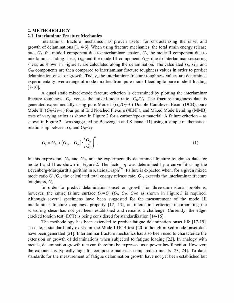
Interlaminar fracture mechanics has proven useful for characterizing the onset and growth of delaminations [1, 4-6]. When using fracture mechanics, the total strain energy release rate, GT, the mode I component due to interlaminar tension, GI, the mode II component due to interlaminar sliding shear, GII, and the mode III component, GIII, due to interlaminar scissoring shear, as shown in Figure 1, are calculated along the delamination. The calculated GI, GII, and GIII components are then compared to interlaminar fracture toughness values in order to predict delamination onset or growth. Today, the interlaminar fracture toughness values are determined experimentally over a range of mode mixities from pure mode I loading to pure mode II loading [7-10].
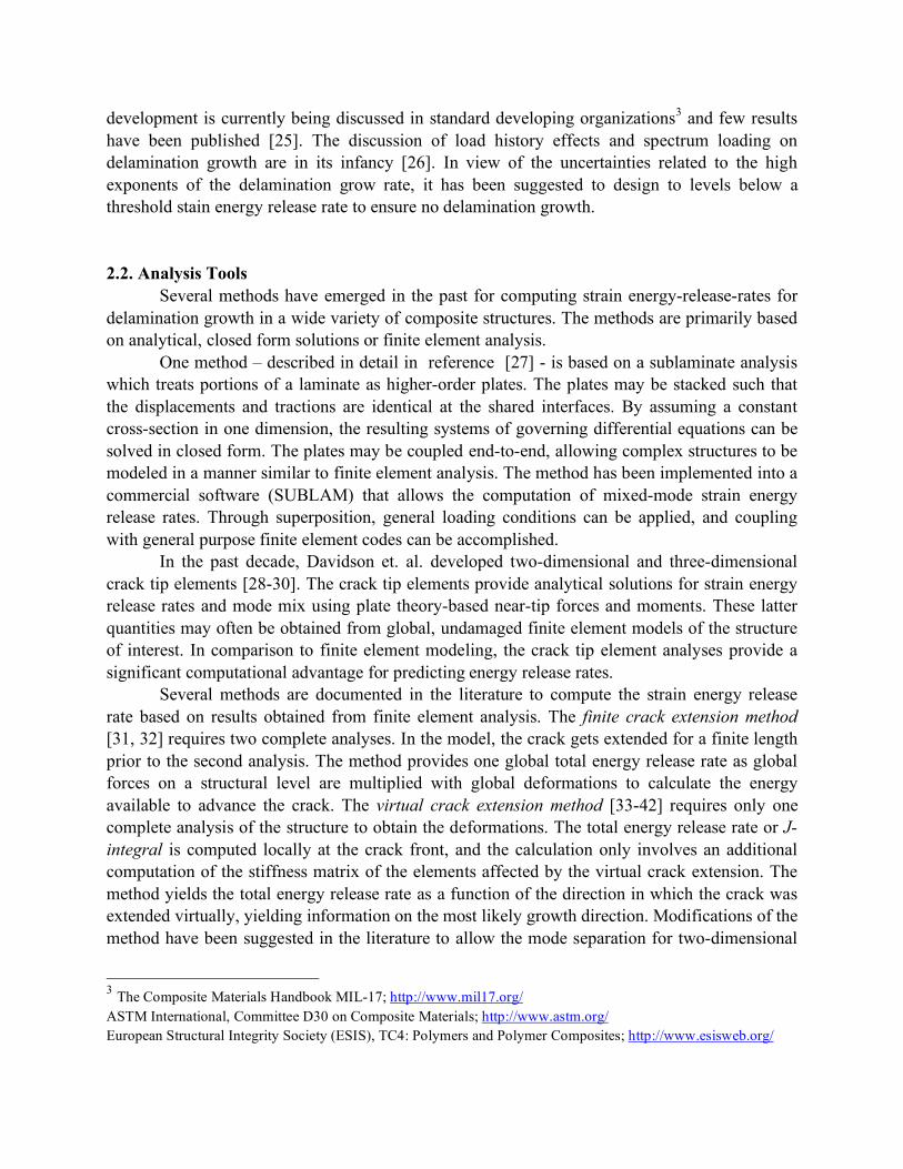
A quasi static mixed-mode fracture criterion is determined by plotting the interlaminar fracture toughness, Gc, versus the mixed-mode ratio, GII/GT. The fracture toughness data is generated experimentally using pure Mode I (GII/GT=0) Double Cantilever Beam (DCB), pure Mode II (GII/GT=1) four point End Notched Flexure (4ENF), and Mixed Mode Bending (MMB) tests of varying ratios as shown in Figure 2 for a carbon/epoxy material. A failure criterion – as shown in Figure 2 - was suggested by Benzeggah and Kenane [11] using a simple mathematical relationship between Gc and GII/GT
!
Gc
=GIc
+ GIIc"G
Ic( ) #G
II
GT
$
% &
'
( )
*
. (1)
In this expression, GIc and GIIc are the experimentally-determined fracture toughness data for mode I and II as shown in Figure 2. The factor
!
" was determined by a curve fit using the Levenberg-Marquardt algorithm in KaleidaGraphTM. Failure is expected when, for a given mixed mode ratio GII/GT, the calculated total energy release rate, GT, exceeds the interlaminar fracture toughness, Gc.
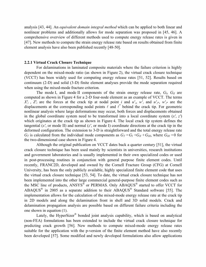
In order to predict delamination onset or growth for three-dimensional problems, however, the entire failure surface Gc=Gc (GI, GII, GIII) as shown in Figure 3 is required. Although several specimens have been suggested for the measurement of the mode III interlaminar fracture toughness property [12, 13], an interaction criterion incorporating the scissoring shear has not yet been established and remains a challenge. Currently, the edge-cracked torsion test (ECT) is being considered for standardization [14-16].
The methodology has been extended to predict fatigue delamination onset life [17-19]. To date, a standard only exists for the Mode I DCB test [20] although mixed-mode onset data have been generated [21]. Interlaminar fracture mechanics has also been used to characterize the extension or growth of delaminations when subjected to fatigue loading [22]. In analogy with metals, delamination growth rate can therefore be expressed as a power law function. However, the exponent is typically high for composite materials compared to metals [23, 24]. To date, standards for the measurement of fatigue delamination growth have not yet been established but
development is currently being discussed in standard developing organizations3 and few results have been published [25]. The discussion of load history effects and spectrum loading on delamination growth are in its infancy [26]. In view of the uncertainties related to the high exponents of the delamination grow rate, it has been suggested to design to levels below a threshold stain energy release rate to ensure no delamination growth.
2.2. Analysis Tools Several methods have emerged in the past for computing strain energy-release-rates for
delamination growth in a wide variety of composite structures. The methods are primarily based on analytical, closed form solutions or finite element analysis.
One method – described in detail in reference [27] - is based on a sublaminate analysis which treats portions of a laminate as higher-order plates. The plates may be stacked such that the displacements and tractions are identical at the shared interfaces. By assuming a constant cross-section in one dimension, the resulting systems of governing differential equations can be solved in closed form. The plates may be coupled end-to-end, allowing complex structures to be modeled in a manner similar to finite element analysis. The method has been implemented into a commercial software (SUBLAM) that allows the computation of mixed-mode strain energy release rates. Through superposition, general loading conditions can be applied, and coupling with general purpose finite element codes can be accomplished.
In the past decade, Davidson et. al. developed two-dimensional and three-dimensional crack tip elements [28-30]. The crack tip elements provide analytical solutions for strain energy release rates and mode mix using plate theory-based near-tip forces and moments. These latter quantities may often be obtained from global, undamaged finite element models of the structure of interest. In comparison to finite element modeling, the crack tip element analyses provide a significant computational advantage for predicting energy release rates.
Several methods are documented in the literature to compute the strain energy release rate based on results obtained from finite element analysis. The finite crack extension method [31, 32] requires two complete analyses. In the model, the crack gets extended for a finite length prior to the second analysis. The method provides one global total energy release rate as global forces on a structural level are multiplied with global deformations to calculate the energy available to advance the crack. The virtual crack extension method [33-42] requires only one complete analysis of the structure to obtain the deformations. The total energy release rate or J-integral is computed locally at the crack front, and the calculation only involves an additional computation of the stiffness matrix of the elements affected by the virtual crack extension. The method yields the total energy release rate as a function of the direction in which the crack was extended virtually, yielding information on the most likely growth direction. Modifications of the method have been suggested in the literature to allow the mode separation for two-dimensional
3 The Composite Materials Handbook MIL-17; http://www.mil17.org/ ASTM International, Committee D30 on Composite Materials; http://www.astm.org/ European Structural Integrity Society (ESIS), TC4: Polymers and Polymer Composites; http://www.esisweb.org/
analysis [43, 44]. An equivalent domain integral method which can be applied to both linear and nonlinear problems and additionally allows for mode separation was proposed in [45, 46]. A comprehensive overview of different methods used to compute energy release rates is given in [47]. New methods to compute the strain energy release rate based on results obtained from finite element analysis have also been published recently [48-50].
2.2.1 Virtual Crack Closure Technique For delaminations in laminated composite materials where the failure criterion is highly
dependent on the mixed-mode ratio (as shown in Figure 2), the virtual crack closure technique (VCCT) has been widely used for computing energy release rates [51, 52]. Results based on continuum (2-D) and solid (3-D) finite element analyses provide the mode separation required when using the mixed-mode fracture criterion.
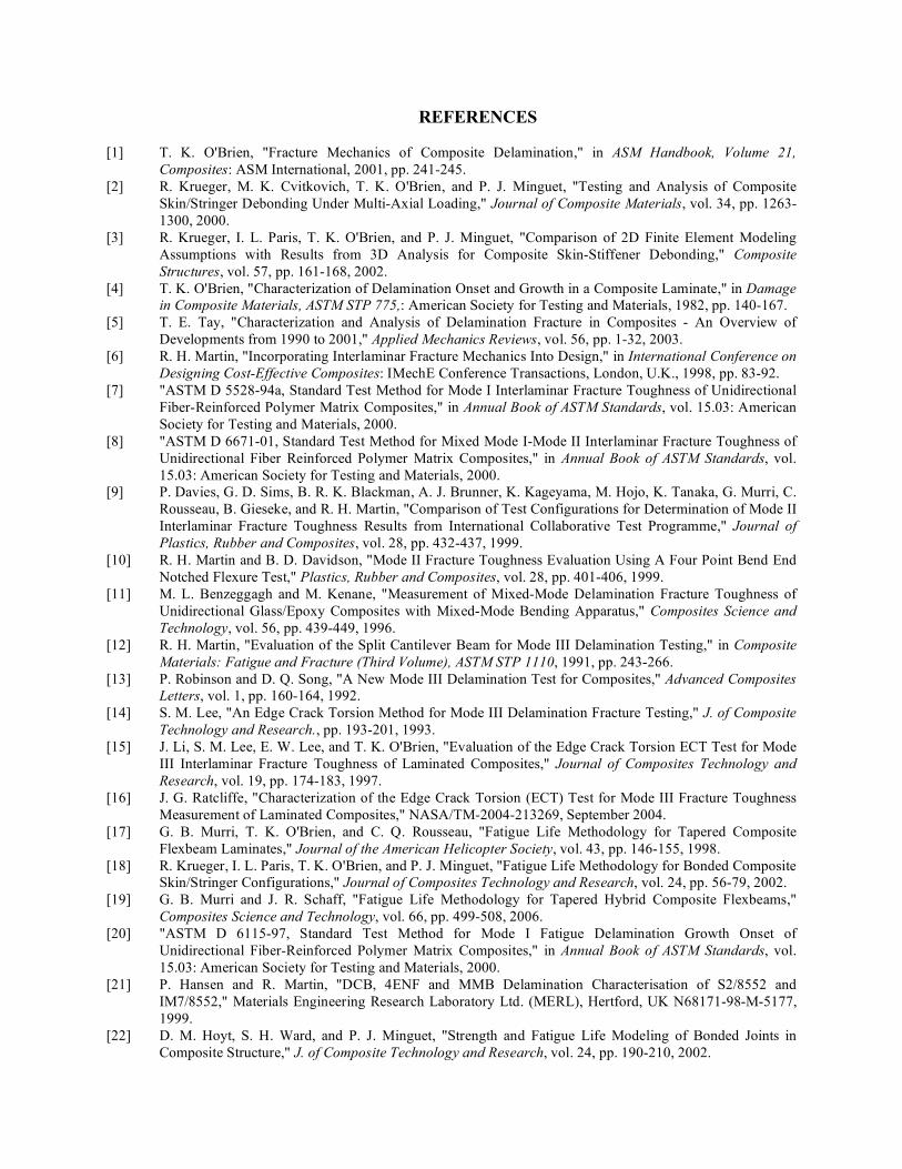
The mode I, and mode II components of the strain energy release rate, GI, GII are computed as shown in Figure 4 for a 2-D four-node element as an example of VCCT. The terms X'i , Z'i are the forces at the crack tip at nodal point i and u'l, w'l and u'l*, w'l* are the displacements at the corresponding nodal points l and l* behind the crack tip. For geometric nonlinear analysis where large deformations may occur, both forces and displacements obtained in the global coordinate system need to be transformed into a local coordinate system (x', z') which originates at the crack tip as shown in Figure 4. The local crack tip system defines the tangential (x', or mode II) and normal (z', or mode I) coordinate directions at the crack tip in the deformed configuration. The extension to 3-D is straightforward and the total energy release rate GT is calculated from the individual mode components as GT =GI +GII +GIII, where GIII =0 for the two-dimensional case shown in Figure 4.
Although the original publication on VCCT dates back a quarter century [51], the virtual crack closure technique has been used mainly by scientists in universities, research institutions and government laboratories and is usually implemented in their own specialized codes or used in post-processing routines in conjunction with general purpose finite element codes. Until recently, FRANC2D, developed and owned by the Cornell Fracture Group (CFG) at Cornell University, has been the only publicly available, highly specialized finite element code that uses the virtual crack closure technique [53, 54]. To date, the virtual crack closure technique has not been implemented into the other large commercial general-purpose finite element codes such as the MSC line of products, ANSYS® or PERMAS. Only ABAQUS® started to offer VCCT for ABAQUS® in 2005 as a separate addition to their ABAQUS® Standard software [55]. The implementation allows for the calculation of the mixed-mode energy release rate at the crack tip in 2D models and along the delamination front in shell and 3D solid models. Crack and delamination propagation analysis are possible based on different failure criteria including the one shown in equation (1).
Lately, the HyperSizer® bonded joint analysis capability, which is based on analytical (non-FEA) formulations has been extended to include the virtual crack closure technique for predicting crack growth [56]. New methods to compute mixed-mode energy release rates suitable for the application with the p-version of the finite element method have also recently been developed [57]. Some modified and newly developed formulations also allow applications

independent of the finite element analysis and are suitable for boundary element analysis [54, 58].
2.2.2 A Global/Local Shell 3D Modeling Technique Built-up structures are traditionally modeled and analyzed using plate or shell finite
elements to keep the modeling and computational effort affordable. Computed mixed mode strain energy release rate components, however, depend on many variables such as element order and shear deformation assumptions, kinematic constraints in the neighborhood of the delamination front, and continuity of material properties and section stiffness in the vicinity of the debond when delaminations or debonds are modeled with plate or shell finite elements [59-61]. These problems may be avoided by using three-dimensional models. Since many layers of brick elements through the thickness are often necessary to model the individual plies, however, the size of finite element models required for accurate analyses may become prohibitively large.
For detailed modeling and analysis of the delaminations, the shell/3D modeling technique will reduce the modeling time since existing plate or shell models may be modified to shell/3D models. This is a considerable advantage compared to the creation of an entirely new three-dimensional finite element model. The technique will also reduce computational time because only a relatively small section of interest needs to modeled with solid elements keeping the number of unknowns small. The technique combines the accuracy of the full three-dimensional solution with the computational efficiency of a plate or shell finite element model and has been demonstrated for various applications such as fracture toughness characterization specimens [62] and on the coupon level for the skin/stringer separation specimen [63, 52]
3. STRINGER STIFFENED PANEL For the demonstration of a fracture mechanics methodology on the structural level, a
stringer stiffened panel as shown in Figure 5, was selected and analyzed. The square panel is made of carbon/epoxy tape and reinforced with three stringers made of carbon/epoxy plain weave fabric. The stiffened panel is bolted to a steel picture frame and subjected to pure in-plane shear loading. During manufacturing, an artificial defect had been placed at the termination of the center stiffener. Sufficient shear loading causes the panel to buckle as shown in Figure 5. The resulting out-of-plane deformation causes skin/stringer separation at the location of the initial defect as shown in the detail of the deformed mesh in Figure 5. A total of eight delamination lengths between 81.9 and 355.6 mm were modeled. The initial length corresponds to the length of the insert used to create an initial defect at the termination of the center stringer. Additional lengths were chosen to study the change in energy release rate distribution across the width of the stringer with increasing delamination length. The mixed-mode strain energy release rates were calculated using the virtual crack closure technique across the width of the stringer foot. A failure index was calculated by correlating the results with the mixed-mode failure criterion of the graphite/epoxy material.

3.1 Finite Element Model The global model representing the steel loadframe, the graphite tape/epoxy panel and the
graphite fabric/epoxy stringers was created using standard S4 shell elements available in the finite element software ABAQUS®. To accurately model earlier tests, which were performed under constant displacement control, uniform displacements u,v were applied at one corner node to introduce shear as shown in Figure 5. The inplane displacements u,v were suppressed at the diagonally opposite corner, and the out of plane displacements w were suppressed along all four edges across the entire width of the steel load frame.
At the stringer termination, shell elements representing the foot of the stringer and the panel were removed from the original shell model. The shell elements used to model the flange web and hat were not removed. A local 3D FE-model containing a straight delamination front was generated using C3D8I solid brick elements and inserted into the global shell model as shown in the detail of Figure 5. The local 3D model consists of an intact section and a delaminated section with a fine mesh around the delamination front. The plane of delamination is located at the bondline between stringer foot and the panel. The delamination was modeled as a discrete discontinuity using two unconnected nodes with identical coordinates, one on each side of the delamination. A refined mesh as shown in Figure 5 was used along the stringer boundary in order to capture edge effects. Using the finite sliding option available in ABAQUS®, contact was modeled between the delaminated surfaces to avoid interpenetration during analysis. The local 3D model was connected with the shell model using the shell to solid coupling option in ABAQUS® which allows the connection between non-conforming shell and solid models. For the entire investigation of the panel buckling, the ABAQUS® geometric nonlinear analysis procedure was used. Additional modeling details are described in reference [64].
3.2 Calculation of Mixed-Mode Strain Energy Release Rates and Failure Indices
The virtual crack closure technique (VCCT) – discussed earlier - was used to calculate the mode contributions GI, GII and GIII, the total energy release rate GT=GI+GII+GIII, as well as the mixed mode ratios GS/GT along the delamination front across the width of the stringer for all delamination lengths modeled. Here, GS denotes the sum of the in-plane shearing components GII+GIII. For two-dimensional analyses, where GIII=0, this definition is equal to the commonly used definition of the mixed mode ratio, GII /GT. For three-dimensional analysis, which also yields results for the scissoring mode GIII, the modified definition of GS is introduced since a mixed-mode failure criterion, which accounts for all three modes is currently not available.
For each nodal point along the delamination front, the critical energy release rate Gc was calculated from the mixed mode failure criterion for graphite/epoxy (Figure 2)
!
Gc
= 207.7 +1126.8 "G
S
GT
#
$ %
&
' (
4.46
. (2)
for the computed mixed-mode ratio GS/GT at each point. Subsequently, the failure index GT/Gc was determined with the assumption that delamination propagation occurs for

!
GT
Gc
"1. (3)
For all delamination lengths modeled, the computed failure indices were calculated for
every fifth load increment plus the final increment and plotted versus the dimensionless coordinate s across the width of the stringer b (see detail in Figure 5)
!
s y( ) =y " y
0
b; 0.0 # s #1.0 . (4)
At the left edge of the stringer, the nodal point coordinates are equal to y=y0 which yields s=0.0, and the right edge nodal point coordinates are equal to y=yb which results in s=1.0 as depicted in Figure 5.
The calculated failure index for delamination length a=81.9 mm is shown in Figure 6 for selected analysis increments only. The failure index peaked at the edges (s=0.0 and s=1.0) with an additional peak around the center (s~0.5) underneath the stringer. Early in the analysis (small increment numbers), which corresponds to small applied displacements (u=v), the failure index GT/Gc is well below unity across the entire width. This result indicates that the delamination is not going to grow. With increasing load, the failure index approaches unity first near one edge where failure is expected to initiate. Generally, for the next load increment, the index is well above unity across the entire width. For the longer delaminations (a=101.6 mm and a=355.6 mm) which are associated with a different global buckling pattern, the distribution across the width changes, the failure index peaks in the center underneath the stringer web and is reduced toward the edges as discussed in detail in reference [64].
A different way to visualize the results is to plot the critical displacement, i.e. the applied displacement (u or v) for which GT/Gc=1.0, at the center of the specimen (s=0.5) versus the delamination length as shown in Figure 7. The critical displacements for delamination lengths of a=81.9 mm, 88.9 mm, and 94.9 mm, were almost identical. For the longer delaminations modeled (a=101.6 mm up to 355.6 mm), the critical displacements are significantly lower, which suggests that rapid delamination progress is to be expected once the delamination starts to propagate for a critical applied displacement. Analysis and result details are described in reference [64]. CONCLUDING REMARKS
For laminated composite materials, fracture mechanics has proven useful for characterizing the onset of delaminations in composites. To fully understand this failure mechanism, the mixed-mode strain energy release rates need to be calculated and compared to interlaminar fracture toughness properties experimentally measured over a range from pure mode I loading to pure mode II loading.
It is state of the art to determine mode I fracture toughness using Double Cantilever Beam (DCB) and mode II fracture toughness using End Notched Flexure (ENF) tests. The

Mixed Mode Bending (MMB) tests is used to determine the fracture toughness of varying mixed-mode ratios. Although several different types of test specimens have also been suggested for the measurement of the mode III interlaminar fracture toughness property, an interaction criterion incorporating the scissoring shear, has not yet been established and remains a challange.
The methodology described above has been extended to predict fatigue delamination onset life, but to date a standard only exists for the Mode I DCB test. Interlaminar fracture mechanics has also been used to characterize the extension or growth of delaminations when subjected to fatigue loading. Standards for the measurement of fatigue delamination growth have not yet been established and remain a challenge.
Today, a variety of methods are used to compute the strain energy release rate based on results obtained from finite element analysis. The virtual crack closure technique (VCCT) is widely used for computing mixed-mode strain energy release rates based on results from finite element analyses. Currently, VCCT has only been implemented into the commercial finite element software ABAQUS®whereas other large commercial finite element codes do not offer any choice for calculating mixed mode energy release rates today. The implementation of methods to compute mixed mode energy release rates into these codes remains a challenge.
To date, interlaminar fracture mechanics has been used with limited success primarily to investigate onset in fracture toughness specimens and laboratory size coupon type specimens. Future acceptance of the methodology by industry and certification authorities requires the validation and verification of the methodology and successful demonstration on the structural level. The skin/stringer separation of a graphite/epoxy composite panel reinforced with three stringers and subjected to pure shear loading was analyzed to demonstrate the state-of-the-art application on the structural level. Full implementation of Interlaminar Fracture Mechanics in design, however remains a challenge and requires advancements in delamination onset and growth criteria under mixed mode conditions and continuing development effort of codes to calculate energy release rates. ACKNOWLEDGEMENTS
The skin/stringer separation analysis was supported by The Boeing Company and the Aviation Applied Technology Directorate under Technology Investment Agreement No. DAAH10-02-2-0001 as part of the Survivable, Affordable, Repairable, Airframe Program (SARAP).
REFERENCES
[1] T. K. O'Brien, "Fracture Mechanics of Composite Delamination," in ASM Handbook, Volume 21, Composites: ASM International, 2001, pp. 241-245.
[2] R. Krueger, M. K. Cvitkovich, T. K. O'Brien, and P. J. Minguet, "Testing and Analysis of Composite Skin/Stringer Debonding Under Multi-Axial Loading," Journal of Composite Materials, vol. 34, pp. 1263-1300, 2000.
[3] R. Krueger, I. L. Paris, T. K. O'Brien, and P. J. Minguet, "Comparison of 2D Finite Element Modeling Assumptions with Results from 3D Analysis for Composite Skin-Stiffener Debonding," Composite Structures, vol. 57, pp. 161-168, 2002.
[4] T. K. O'Brien, "Characterization of Delamination Onset and Growth in a Composite Laminate," in Damage in Composite Materials, ASTM STP 775,: American Society for Testing and Materials, 1982, pp. 140-167.
[5] T. E. Tay, "Characterization and Analysis of Delamination Fracture in Composites - An Overview of Developments from 1990 to 2001," Applied Mechanics Reviews, vol. 56, pp. 1-32, 2003.
[6] R. H. Martin, "Incorporating Interlaminar Fracture Mechanics Into Design," in International Conference on Designing Cost-Effective Composites: IMechE Conference Transactions, London, U.K., 1998, pp. 83-92.
[7] "ASTM D 5528-94a, Standard Test Method for Mode I Interlaminar Fracture Toughness of Unidirectional Fiber-Reinforced Polymer Matrix Composites," in Annual Book of ASTM Standards, vol. 15.03: American Society for Testing and Materials, 2000.
[8] "ASTM D 6671-01, Standard Test Method for Mixed Mode I-Mode II Interlaminar Fracture Toughness of Unidirectional Fiber Reinforced Polymer Matrix Composites," in Annual Book of ASTM Standards, vol. 15.03: American Society for Testing and Materials, 2000.
[9] P. Davies, G. D. Sims, B. R. K. Blackman, A. J. Brunner, K. Kageyama, M. Hojo, K. Tanaka, G. Murri, C. Rousseau, B. Gieseke, and R. H. Martin, "Comparison of Test Configurations for Determination of Mode II Interlaminar Fracture Toughness Results from International Collaborative Test Programme," Journal of Plastics, Rubber and Composites, vol. 28, pp. 432-437, 1999.
[10] R. H. Martin and B. D. Davidson, "Mode II Fracture Toughness Evaluation Using A Four Point Bend End Notched Flexure Test," Plastics, Rubber and Composites, vol. 28, pp. 401-406, 1999.
[11] M. L. Benzeggagh and M. Kenane, "Measurement of Mixed-Mode Delamination Fracture Toughness of Unidirectional Glass/Epoxy Composites with Mixed-Mode Bending Apparatus," Composites Science and Technology, vol. 56, pp. 439-449, 1996.
[12] R. H. Martin, "Evaluation of the Split Cantilever Beam for Mode III Delamination Testing," in Composite Materials: Fatigue and Fracture (Third Volume), ASTM STP 1110, 1991, pp. 243-266.
[13] P. Robinson and D. Q. Song, "A New Mode III Delamination Test for Composites," Advanced Composites Letters, vol. 1, pp. 160-164, 1992.
[14] S. M. Lee, "An Edge Crack Torsion Method for Mode III Delamination Fracture Testing," J. of Composite Technology and Research., pp. 193-201, 1993.
[15] J. Li, S. M. Lee, E. W. Lee, and T. K. O'Brien, "Evaluation of the Edge Crack Torsion ECT Test for Mode III Interlaminar Fracture Toughness of Laminated Composites," Journal of Composites Technology and Research, vol. 19, pp. 174-183, 1997.
[16] J. G. Ratcliffe, "Characterization of the Edge Crack Torsion (ECT) Test for Mode III Fracture Toughness Measurement of Laminated Composites," NASA/TM-2004-213269, September 2004.
[17] G. B. Murri, T. K. O'Brien, and C. Q. Rousseau, "Fatigue Life Methodology for Tapered Composite Flexbeam Laminates," Journal of the American Helicopter Society, vol. 43, pp. 146-155, 1998.
[18] R. Krueger, I. L. Paris, T. K. O'Brien, and P. J. Minguet, "Fatigue Life Methodology for Bonded Composite Skin/Stringer Configurations," Journal of Composites Technology and Research, vol. 24, pp. 56-79, 2002.
[19] G. B. Murri and J. R. Schaff, "Fatigue Life Methodology for Tapered Hybrid Composite Flexbeams," Composites Science and Technology, vol. 66, pp. 499-508, 2006.
[20] "ASTM D 6115-97, Standard Test Method for Mode I Fatigue Delamination Growth Onset of Unidirectional Fiber-Reinforced Polymer Matrix Composites," in Annual Book of ASTM Standards, vol. 15.03: American Society for Testing and Materials, 2000.
[21] P. Hansen and R. Martin, "DCB, 4ENF and MMB Delamination Characterisation of S2/8552 and IM7/8552," Materials Engineering Research Laboratory Ltd. (MERL), Hertford, UK N68171-98-M-5177, 1999.
[22] D. M. Hoyt, S. H. Ward, and P. J. Minguet, "Strength and Fatigue Life Modeling of Bonded Joints in Composite Structure," J. of Composite Technology and Research, vol. 24, pp. 190-210, 2002.
[23] R. H. Martin and G. B. Murri, "Characterization of Mode I and Mode II Delamination Growth and Thresholds in AS4/PEEK Composites," in Composite Materials: Testing and Design (Ninth Volume), ASTM STP 1059: American Society for Testing and Materials, 1990, pp. 251-270.
[24] M. König, R. Krüger, K. Kussmaul, M. v. Alberti, and M. Gädke, "Characterizing Static and Fatigue Interlaminar Fracture Behaviour of a First Generation Graphite/Epoxy Composite," in Composite Materials: Testing and Design - (13th Vol.), ASTM STP 1242, S. J. Hooper, Ed.: American Society for Testing and Materials, 1997, pp. 60-81.
[25] K. Shivakumar, H. Chen, F. Abali, D. Le, and C. Davis, "A Total Fatigue Life Model for Mode I Delaminated Composite Laminates," International Journal of Fatigue, vol. 28, pp. 33-42, 2006.
[26] R. Martin, "Load History Effects on Delamination Growth in Composite Materials," presented at Mil-Handbook 17 Meeting, Charleston, South Carolina, USA, 2003.
[27] G. Flanagan, "A General Sublaminate Analysis Method for Determining Strain Energy Release Rates in Composites," in The 35th AIAA/ASME/ASCE/AHS/ASC Structures, Structural Dynamics and Materials Conference, 1994, pp. 381-389.
[28] B. D. Davidson, "Analytical Determination of Mixed-Mode Energy Release Rates for Delamination Using a Crack Tip Element," in Fracture of Composites, vol. 120-121, Key Engineering Materials, E. A. Armanios, Ed.: Trans Tech Publications, 1996, pp. 161-180.
[29] L. Yu and B. D. Davidson, "A Three-Dimensional Crack Tip Element for Energy Release Rate Determination in Layered Elastic Structures," Journal of Composite Materials, vol. 35, pp. 457-488, 2001.
[30] B. D. Davidson and L. Yu, "Energy Release Rate Prediction in Stiffened-skin Structure Using a Three-dimensional Crack Tip Element Analysis," Journal of Composite Materials, vol. 39, pp. 1819-1842, 2005.
[31] J. St. Doltsinis, H. Knapp, P. Streiner, and H. Wüstenberg, "PERMAS-FM, Fracture Mechanics," INTES GmbH, Stuttgart, User Manual, Publication No. 226, Rev. C, 1985.
[32] R. Krüger, M. König, and T. Schneider, "Computation of Local Energy Release Rates Along Straight and Curved Delamination Fronts of Unidirectionally Laminated DCB- and ENF - Specimens," in Proceedings of the 34th AIAA/ASME/ASCE/AHS/ASC SSDM Conference, La Jolla, CA: American Institute of Aeronautics and Astronautics, Washington, 1993, pp. 1332-1342.
[33] T. K. Hellen, "On the Method of Virtual Crack Extension," Int. J. Num. Meth. Eng., vol. 9, pp. 187-207, 1975.
[34] D. M. Parks, "A Stiffness Derivative Finite Element Technique for Determination of Crack Tip Stress Intensity Factors," Int. J. Fracture, vol. 10, pp. 487-502, 1974.
[35] D. M. Parks, "The Virtual Crack Extension Method For Nonlinear Material Behaviour," Comput. Methods Appl. Mech. Eng., vol. 12, pp. 353-364, 1977.
[36] D. M. Parks, "Virtual Crack Extension: A General Finite Element Technique for J-Integral Evaluation," in Numerical Methods in Fracture Mechanics, A. R. Luxmoore and D. R. J. Owen, Eds., 1978, pp. 464-479.
[37] H. G. Delorenzi, "On the Energy Release Rate and the J-integral for 3-D Crack Configurations," Int. J. Fracture, vol. 19, pp. 183-193, 1982.
[38] H. G. Delorenzi, "Energy Release Rate Calculations by the Finite Element Method," Eng. Fracture Mech., vol. 21, pp. 129-143, 1985.
[39] H. G. Delorenzi and C. D. Shih, "3-D Elastic-Plastic Investigation of Fracture Parameters in Side-Grooved Compact Specimen," Int. J. Fracture, vol. 21, pp. 195-220, 1983.
[40] S. C. Lin and J. F. Abel, "Variational Approach for a New Direct-Integration form of the Virtual Crack Extension Method," International Journal of Fracture, vol. 38, pp. 217-235, 1988.
[41] P. W. Claydon, "Maximum Energy Release Rate Distribution From a Generalized 3D Virtual Crack Extension Method," Engineering Fracture Mechanics, vol. 42, pp. 961-969, 1992.
[42] C. G. Hwang, P. A. Wawrzynek, A. K. Tayebi, and A. R. Ingraffea, "On the Virtual Crack Extension Method for Calculation of the Rates of Energy Release Rate," Engineering Fracture Mechanics, vol. 59, pp. 521-542, 1998.
[43] H. Ishikawa, "A Finite Element Analysis of Stress Intensity Factors for Combined Tensile and Shear Loading by Only a Virtual Crack Extension," Int. J. Fracture, vol. 16, pp. R243-R246, 1980.
[44] G. T. Sha, "On the Virtual Crack Extension Technique for Stress Intensity Factors and Energy Release Rate Calculations for Mixed Fracture Mode," Int. J. Fracture, vol. 25, pp. R33-R42, 1984.
[45] K. N. Shivakumar and I. S. Raju, "An Equivalent Domain Integral Method for Three-Dimensional Mixed-Mode Fracture Problems," Engineering Fracture Mechanics, vol. 42, pp. 935-959, 1992.
[46] I. S. Raju and K. N. Shivakumar, "An Equivalent Domain Integral Method in the Two-Dimensional Analysis Mixed-Mode Crack Problems," Engineering Fracture Mechanics, vol. 37, pp. 707-725, 1990.

[47] L. Banks-Sills, "Application of the Finite Element Method to Linear Elastic Fracture mechanics," Applied Mechanics Reviews, vol. 44, pp. 447-461, 1991.
[48] W. T. Chow and S. N. Atluri, "Stress Intensity Factors as the Fracture Parameters for Delamination Crack Growth in Composite Laminates," Composites, Part B, vol. 28B, pp. 375-384, 1997.
[49] M. Gosz and B. Moran, "An Interaction Energy Integral Method for Computation of Mixed-Mode Stress Intensity Factors Along Non-Planar Crack Fronts in Three Dimensions," Engineering Fracture Mechanics, vol. 69, pp. 299-319, 2002.
[50] O. Park and B. V. Sankar, "Crack-Tip Force Method for Computing Energy Release Rate in Delaminated Plates," Composite Structures, vol. 55, pp. 429-434, 2002.
[51] E. F. Rybicki and M. F. Kanninen, "A Finite Element Calculation of Stress Intensity Factors by a Modified Crack Closure Integral," Eng. Fracture Mech., vol. 9, pp. 931-938, 1977.
[52] R. Krueger, "The Virtual Crack Closure Technique: History, Approach and Applications," Applied Mechanics Reviews, vol. 57, pp. 109-143, 2004.
[53] A. Ingraffea and P. Wawrzynek, "FRANC2D: A Case Study in Transfer of Software Technology," in Research Transformed into Practice: Implementations of NSF Research, J. Colville and A. Amde, Eds.: ASCE Press, New York, pp. 233-344, 1995
[54] R. Singh, B. J. Carter, P. A. Wawrzynek, and A. R. Ingraffea, "Universal Crack Closure Integral for SIF Estimation," Engineering Fracture Mechanics, vol. 60, pp. 133-146, 1998.
[55] "VCCT for ABAQUS - User's Manual," ABAQUS 2005. [56] P. W. Yarrington, C. S. Collier, and B. A. Bednarcyk, "Failure Analysis of Adhesively Bonded Composite
Joints via the Virtual Crack Closure Technique," American Institute of Aeronautics and Astronautics, AIAA-2006-1962, 2006.
[57] J. Schön and B. Andersson, "Calculation of Mode-Separated Energy Release Rates During Delamination Growth," in Proceedings of the American Society for Composites - 13th Technical Conference on Composite Materials, 1998.
[58] N. K. Mukhopadhyay, A. Kakodkar, and S. K. Maiti, "Further Considerations in Modified Crack Closure Integral Based Computation of Stress Intensity Factor in BEM," Engineering Fracture Mechanics, vol. 59, pp. 269-279, 1998.
[59] E. H. Glaessgen, I. S. Raju, and C. C. Poe, "Fracture Mechanics Analysis of Stitched Stiffener-Skin Debonding," in The 39th AIAA/ASME/ASCE/AHS/ASC Structures, Structural Dynamics and Materials Conference, Long Beach, California, AIAA 98-2022, April 20-23, 1998.
[60] E. H. Glaessgen, W. T. Riddell, and I. S. Raju, "Nodal Constraint, Shear Deformation and Continuity Effects Related to the Modeling of Debonding of Laminates, Using Plate Elements," CMES, vol. 3, pp. 103-116, 2002.
[61] J. T. Wang and I. S. Raju, "Strain Energy Release Rate Formulae for Skin-Stiffener Debond Modeled with Plate Elements," Engineering Fracture Mechanics, vol. 54, pp. 211-228, 1996.
[62] R. Krueger and T. K. O'Brien, "A Shell/3D Modeling Technique for the Analysis of Delaminated Composite Laminates," Composites Part A: Applied Science and Manufacturing, vol. 32, pp. 25-44, 2001.
[63] R. Krueger and P. J. Minguet, "Analysis of Composite Skin-stiffener Debond Specimens Using Volume Elements and a Shell/3D Modeling Technique," NASA/CR-2002-211947, ICASE Report No. 2002-38, October 2002.
[64] R. Krueger and P. J. Minguet, "Skin-Stiffener Debond Prediction Based on Computational Fracture Analysis," presented at The Fifth Canadian-International Composites Conference, CANCOM 2005, Vancouver, BC, Canada, 2005.

Figure 3: Mixed mode failure criterion for modes I, II and III.
Failure surface
Gc =Gc(GIc, GIIc, GIIIc)
GIII / GT =0mode I/II interaction only as shown in Figure 2.
GII/ GT =0
mode I/III interaction only
GIII/GT
GIIIc
1.0
GII/GT
GIIc
1.0
0
GIc
GI/ GT =0
mode II/III interaction only
GT
Figure 1: Fracture Modes.
Figure 2: Mixed-mode fracture criterion for a toughened carbon/epoxy.
Interlaminar sliding shearMode II
Interlaminar scissoring shearMode III
Interlaminar tensionMode I
τQ
P
P
experimental datamean values
0
400
800
1200
1600
0 0.2 0.4 0.6 0.8 1Mixed Mode Ratio GII/GT
GC,
J/m2
DCB, Mode I MMB, Mode I and II 4ENF, Mode II
Gc = G
Ic + (GIIc-GIc)(GII/GT)η
Gc = G
Ic + (G
IIc-G
Ic)(G
II/G
T)n
207.7GIc
1334.5GIIc
4.46η
GIc
GIIc

GI = – Z'i ( w'l – w'l * ) / ( 2Δa )
GII = – X'i ( u'l – u'l * ) / ( 2Δa )
x',u',X'
x,u,X
z,w,Z
global system
z',w',Z'local crack tip system
undeformed state(outline)
deformed state
Z'i
X'i
u' *
u'
w' i
k
∆a
crack closed
a
∆a
* w' *
X,Y,Z: forcesu,v,w: displacements
Figure 4: Virtual Crack Closure Technique (VCCT).
Figure 5: Finite Element model of stiffened panel (1016 mm x 1016 mm) and load frame.
intact section delamination front
w=0
w=0
u=v=0
stringer made of carbon/epoxy fabric
steel load framepanel made of carbon/epoxy tape
u=v=6.35 mm
u,v,w: displacements
w=0
x,u
y,v
z,w
detail of local 3D insert
sy=y0s=0.0
y=ybs=1.0
b

0.0
0.5
1.0
1.5
2.0
2.5
3.0
0.0 50.0 100.0 150.0 200.0 250.0 300.0 350.0 400.0
GT/G
c=1.0
Applied displacement
u, mm
Delamination length a, mmFigure 7. Applied external displacement at delamination onset
for different delamination lengths modeled.
a=81.9 mma=88.9 mma=94.6 mm
a=127.0 mm
a=101.6 mm
a=203.2 mm
a=279.4 mm
a=355.6 mm
increment / appl. displ.
0
1
2
3
4
5
00.20.40.60.81
20/0.05225/0.06130/0.09535/0.157
GT/Gc
coordinate s, -
Figure 6. Computed failure index across the width of the stringer for selected increments for delamination length a=81.9 mm.