FracRisk Reporting form for deliverables · FracRisk Reporting form for deliverables ... 2 This...
81
FracRisk Reporting form for deliverables Deliverable Number: D4.1 Work package number: 4 Deliverable title Ranked FEP list Type Report Dissemination Level PU Lead participant EWRE Contributing scientists and other personnel Hagit Wiener, Yoni Goren, Jacob Bensabat, Alexandru Tatomir, Katriona Edlmann, Christopher McDermott With data provided by most participants of the FracRisk project (www.fracrisk.eu). Schedules delivery date from DOW 1/12/2015 Actual / forecast delivery data 24/12/2015 Comments (optional) Click here to enter text. Deliverable summary text: The deliverable presents a list of highest ranked features, events and processes for each focused scenario. The aim of this work is to identify the most relevant FEPs from the comprehensive list of possible environmental impacts that was presented in D3.1. This ranked list will be used as the basis for modelling the critical combinations of subsurface geology, operational practice of hydraulic fracturing. Submitted Click here to enter text. Reviewed Click here to enter text. Final submission Click here to enter text. Ref. Ares(2016)57170 - 06/01/2016
Transcript of FracRisk Reporting form for deliverables · FracRisk Reporting form for deliverables ... 2 This...

FracRisk
Reporting form for deliverables
Deliverable Number: D4.1
Work package number: 4
Deliverable title Ranked FEP list
Type Report
Dissemination Level PU
Lead participant EWRE
Contributing scientists and other personnel Hagit Wiener, Yoni Goren, Jacob Bensabat, Alexandru Tatomir, Katriona Edlmann, Christopher McDermott With data provided by most participants of the FracRisk project (www.fracrisk.eu).
Schedules delivery date from DOW 1/12/2015
Actual / forecast delivery data 24/12/2015
Comments (optional) Click here to enter text.
Deliverable summary text:
The deliverable presents a list of highest ranked features, events and processes for each focused scenario.
The aim of this work is to identify the most relevant FEPs from the comprehensive list of possible environmental impacts that was presented in D3.1.
This ranked list will be used as the basis for modelling the critical combinations of subsurface geology, operational practice of hydraulic fracturing.
Submitted Click here to enter text.
Reviewed Click here to enter text.
Final submission Click here to enter text.
Ref. Ares(2016)57170 - 06/01/2016

2
This project has received funding from the European Union’s Horizon 2020 Research and Innovation programme under Grant Agreement No. 636811
FracRisk: Furthering the Knowledge Base for Reducing the Environmental Footprint of Shale Gas Development
Ranked FEPs list
December 2015

3
This project has received funding from the European Union’s Horizon 2020 Research and Innovation programme under Grant Agreement No. 636811
Contents Introduction .................................................................................................................................................................... 4
1. Methodology ....................................................................................................................................................... 5
2.1 The FEPs appraisal table ......................................................................................................................... 5
2.2 Ranking methodology ............................................................................................................................... 5
1.1.1 Scale points ....................................................................................................................................... 5
2.3 Evaluation methodology .......................................................................................................................... 6
2.4 Collection of the data ............................................................................................................................... 6
2. Results ................................................................................................................................................................... 7
2.1 Highest ranked FEPs .................................................................................................................................. 7
2.1.1 Highest ranked Features ................................................................................................................. 7
2.1.2 Highest ranked Events .................................................................................................................. 12
2.1.3 Highest ranked Processes ............................................................................................................ 16
2.2 Full list of Features and their average grading ............................................................................... 21
2.3 Full list of Events and their average grading ................................................................................... 24
2.4 Full list of Processes and their average grading ............................................................................. 25
References .................................................................................................................................................................. 26
Appendix A – FEP appraisal tables from members of the project ................................................................ 27
List of Figures Figure 1 - Correlation between a feature's average grade and STDEV., FS1 .............................................. 9
Figure 2 - Correlation between a feature's average grade and STDEV., FS2 .............................................. 9 Figure 3 - Correlation between a feature's average grade and STDEV., FS3 ........................................... 10 Figure 4 - Correlation between a feature's average grade and STDEV., FS4 ........................................... 10 Figure 5 - Correlation between a feature's average grade and STDEV., FS5 ........................................... 11 Figure 6 - Correlation between a feature's average grade and STDEV., FS6 ........................................... 11 Figure 7 – Correlation between an event's average grade and STDEV., FS1 ............................................ 13 Figure 8 - Correlation between an event's average grade and STDEV., FS2 ............................................ 13 Figure 9 – Correlation between an event's average grade and STDEV., FS3 ............................................ 14 Figure 10 – Correlation between an event's average grade and STDEV., FS4 ......................................... 14 Figure 11 - Correlation between an event's average grade and STDEV., FS5 .......................................... 15 Figure 12 – Correlation between an event's average grade and STDEV., FS6 ......................................... 15 Figure 13 - Correlation between a process' average grade and STDEV., FS1 .......................................... 18 Figure 14 - Correlation between a process' average grade and STDEV., FS2 .......................................... 18 Figure 15 - Correlation between a process' average grade and STDEV., FS3 .......................................... 19 Figure 16 – Correlation between a process' average grade and STDEV., FS4 ......................................... 19 Figure 17 – Correlation between a process' average grade and STDEV., FS5 ......................................... 20 Figure 18 – Correlation between a process' average grade and STDEV., FS6 ......................................... 20
4
This project has received funding from the European Union’s Horizon 2020 Research and Innovation programme under Grant Agreement No. 636811
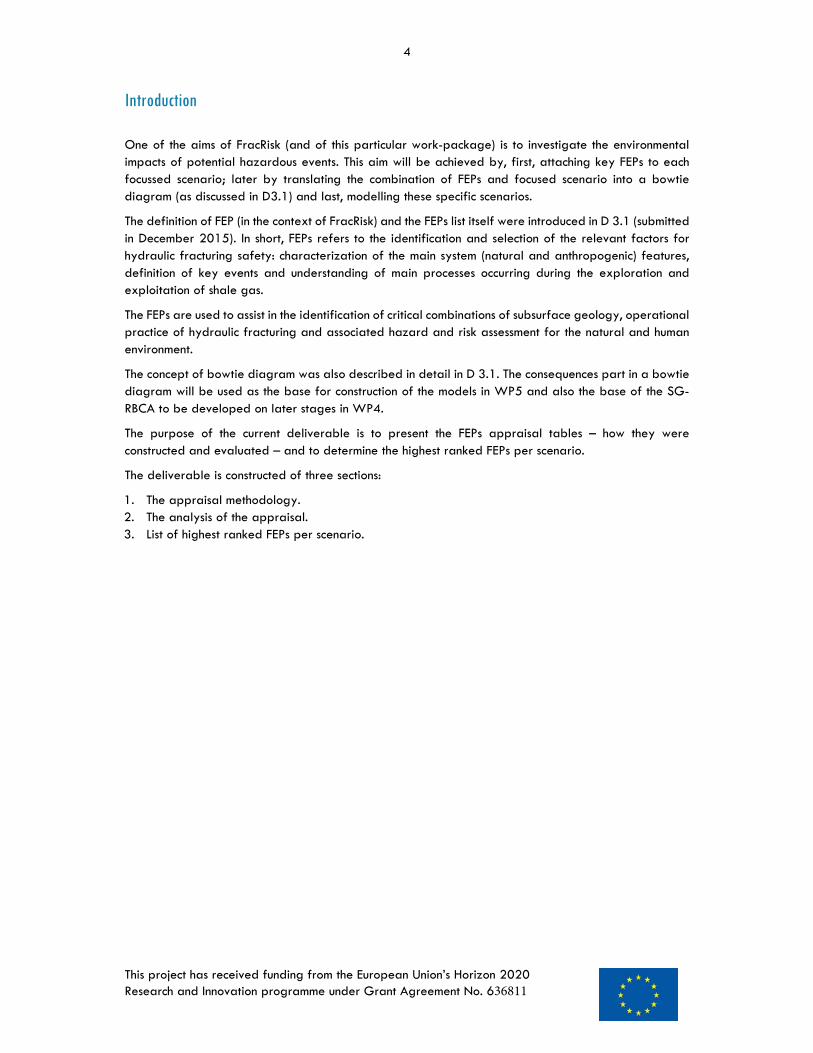
Introduction
One of the aims of FracRisk (and of this particular work-package) is to investigate the environmental impacts of potential hazardous events. This aim will be achieved by, first, attaching key FEPs to each focussed scenario; later by translating the combination of FEPs and focused scenario into a bowtie diagram (as discussed in D3.1) and last, modelling these specific scenarios.
The definition of FEP (in the context of FracRisk) and the FEPs list itself were introduced in D 3.1 (submitted in December 2015). In short, FEPs refers to the identification and selection of the relevant factors for hydraulic fracturing safety: characterization of the main system (natural and anthropogenic) features, definition of key events and understanding of main processes occurring during the exploration and exploitation of shale gas.
The FEPs are used to assist in the identification of critical combinations of subsurface geology, operational practice of hydraulic fracturing and associated hazard and risk assessment for the natural and human environment.
The concept of bowtie diagram was also described in detail in D 3.1. The consequences part in a bowtie diagram will be used as the base for construction of the models in WP5 and also the base of the SG-RBCA to be developed on later stages in WP4.
The purpose of the current deliverable is to present the FEPs appraisal tables – how they were constructed and evaluated – and to determine the highest ranked FEPs per scenario.
The deliverable is constructed of three sections:
1. The appraisal methodology.2. The analysis of the appraisal.3. List of highest ranked FEPs per scenario.

5
This project has received funding from the European Union’s Horizon 2020 Research and Innovation programme under Grant Agreement No. 636811
1. Methodology
2.1 The FEPs appraisal table
The FEP appraisal table (appendix 1) is basically a headline-only version of the FEPs list from D3.1, copied into an Excel file with 3 sheets (one for features, one for events and one for processes). In addition to the FEPs items (columns A and B), 6 columns were assigned for the appraisal of the 6 focused scenarios.
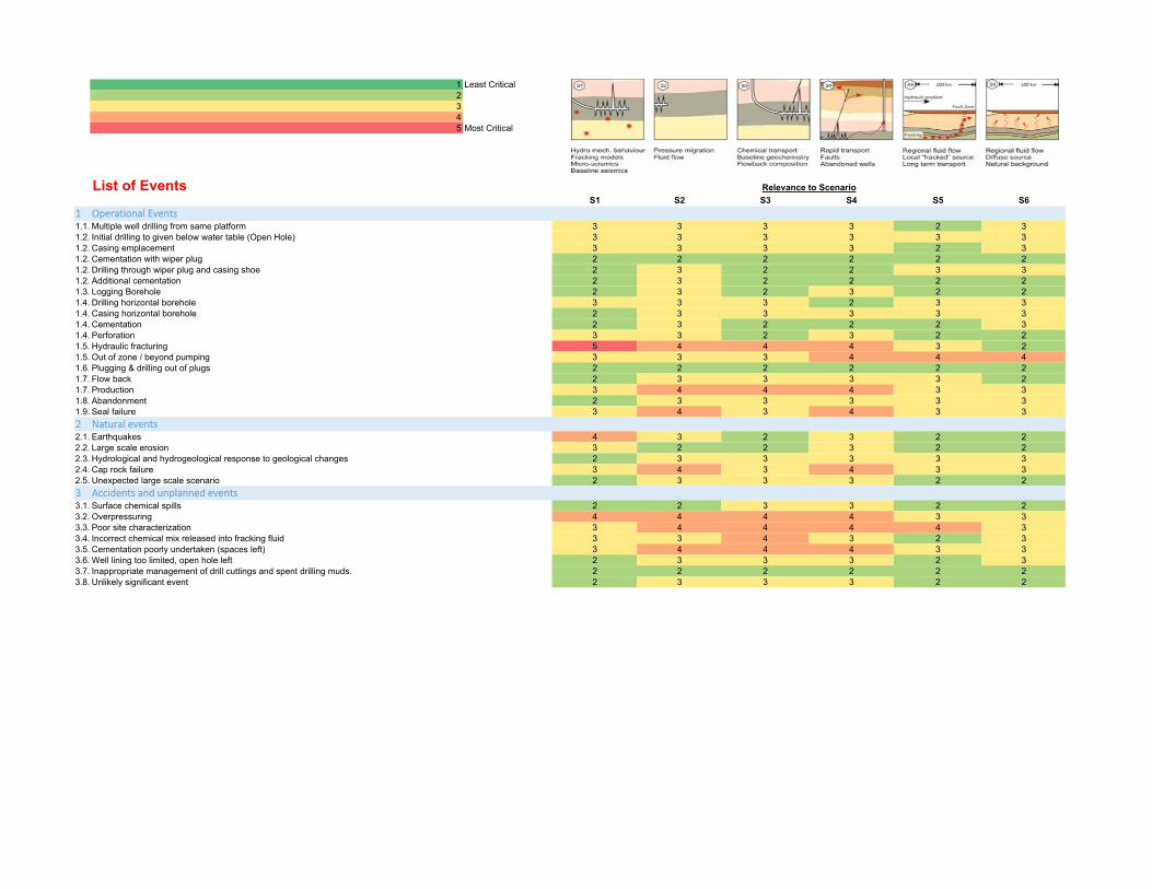
We used a 5 point interval scale, with the following level of importance of each FEP to each scenario:
1– Least critical 2– Slightly critical 3– Critical 4– Considerably critical 5– Most critical
This response scale is a qualitative approach changed to numbers in order to compute an average. Equal intervals are required to represent the same difference between levels of perceived quality (more on the response scale in section 1.2.1).
For each scenario, the participants were asked to assign an importance value (from 1 to 5) for every FEP. The appraisal is per scenario, that is, one can choose similar values for different scenarios (see tables in Appendix 1).
The appraisal tables were sent to all members of the project. There was no limit on the number of tables that each group can send. In some cases there are 2 tables from the same group and in other cases, 2 group members contributed to a single table. For the evaluation part, all tables were given the same weight, without consideration on the amount of contributors or the total amount of tables from the same group.
2.2 Ranking methodology
There are several ways to assign the most relevant elements (in our case items in the FEPs list) to each focused scenarios:
a. Conducting field tests for assessing the importance of each item in the FEPs list.b. Collect data from hydraulic fracturing sites to produce the most common and/or most important
elements.c. Use the wisdom of the crowd for ranking.
Option "a" and "b" are irrelevant because of the enormous size of such a project and the lack of data, respectively.
Option "c" uses the wisdom of the crowd, in our case the knowledge and experience of the project's participants, to rank the items. Oldendick (2008) defined ranking as a question response format used when a researcher is interested in establishing some type of priority among a set of objects. The aim of the survey is to associate to each item in the FEP list an indicator of importance/relevance in connection to each one of the six focus scenarios (presented in the DOW and in D3.1).
1.1.1 Scale points The type of construct described above is a unipolar construct that ranges from least critical (zero importance) to most critical (maximum importance) and there is no precise midpoint. For unipolar construct, Krosnik and Fabrigar (1997) suggest the optimal scale should comprise between 4 to 7 points. It seems likely that people can readily conceive of zero, a slight amount, a moderate amount and a great deal along any unipolar continuum.

6
This project has received funding from the European Union’s Horizon 2020 Research and Innovation programme under Grant Agreement No. 636811
There are a number of arguments in favour of a five-points scale:
a. It's easier to describe five quality levels: least, moderate, important, very, extreme. On a sevenpoint scale it will be too specific and might cause confusion and non-uniformity between therespondents.
b. The survey is very long with three tables, each with tens of items. If using a longer scale, theresponse task might become too demanding, and with too many scale points, the experts mightresort to rounding their answers (Maitland, 2009).
It is important to notice that the literatures cited above refer to surveys measuring attitudes1, for which there are data quality standards such as reliability. However, the FEP appraisal tables were not constructed to include repetitive questions for reliability assessments (although there might be some inherent repetition in the FEPs list).
2.3 Evaluation methodology
The purpose of the FEP appraisal table is to identify among the whole ensemble of FEP's the ones that are most critical for each focus scenario. We performed this identification via a normal average function (see explanations below).
For each item in the FEPs list an average value of importance per scenario was computed. The ranking of the scenarios is carried in an independent manner, i.e., there should not be any link between the ranking process of the different scenarios.
2.4 Collection of the data
All participants of the project received the Excel file and the FEPs list (D3.1) and were asked to fill in the tables and return by email.
Once all the tables were gathered, EWRE staff ran the analyses (average normal, standard deviation and frequency on the average values). The results are described in the next chapter.
1 abstract constructs that are not directly observable and exist only in the respondent’s mind (Maitland 2009)

7
This project has received funding from the European Union’s Horizon 2020 Research and Innovation programme under Grant Agreement No. 636811
2. Results14 appraisal tables were collected.
The following general observations can be made:
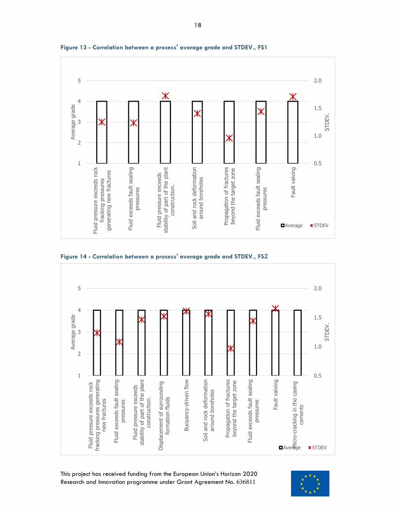
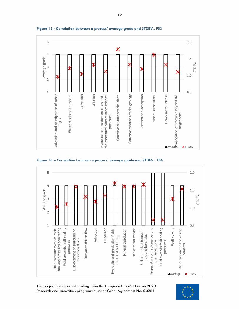
A. The FEPs listed in section 2.1 are those which received an average grade of 4 or 5. The standarddeviations of these grades range from 0.5 to 1.8 (see figures below), which indicate that someFEPs are more agreeable between the respondents than other.
B. Features of the bearing formation and the overburden received, in general, higher rankings thanthose of the underburden and the near surface environment. This is mostly due to the definitionof the focused scenarios, which mainly address the processes that occur in these compartments.
C. Most operational events received an average grade of 3 ("critical") or lower. This may be theresult of two factors: 1) the definitions of operational events were not clear enough for theparticipants to properly evaluate them; 2) these events are not critically important in themodelling to be undertaken in FracRisk.
Natural events and accidents on the other hand, which are more straightforward to understand,received higher scores.
D. Processes received an average higher ranking than the other two tables. To our opinion this isbecause (in contrast to Features and Events), the list of processes is much more bound to theframe work of FracRisk and the questions the focused scenarios are aimed to answer. This willbe taken under consideration as the project evolves, since the FEPs list is aimed to be a generallist regarding most (if not all) facies of hydraulic fracturing.
2.1 Highest ranked FEPs
The FEPs with an average grade of 4 or 5 are presented below for each focused scenario. In brackets, the title of the section under which the feature appears and the relative numbering of the feature (see D3.1 for more information).
2.1.1 Highest ranked Features FS 1:
i. Stress and Mechanical properties (Hydrocarbon bearing formation, 1.1.4)ii. Fractures and faults within the hydrocarbon bearing formation (Hydrocarbon bearing formation,
1.1.6)iii. Lithology (Hydrocarbon bearing formation, 1.1.3.1)iv. Rock / Petrophysical properties of the hydrocarbon bearing formation (Hydrocarbon bearing
formation, 1.1.3)v. Heterogeneity of the hydrocarbon bearing formation (Hydrocarbon bearing formation, 1.1.5)vi. Intrinsic permeability (Hydrocarbon bearing formation, 1.1.3.8)vii. Intrinsic permeability of the fracture (Hydrocarbon bearing formation, 1.1.6.2)viii. Horizontal wells (Site operation, 3.1.1)ix. Well orientation (Site operation, 3.1.7)
FS 2:
i. Rock / Petrophysical properties of the hydrocarbon bearing formation (Hydrocarbon bearingformation, 1.1.3)
ii. Fractures and faults within the hydrocarbon bearing formation (Hydrocarbon bearing formation,1.1.6)
iii. Lithology (Hydrocarbon bearing formation, 1.1.3.1)iv. Intrinsic permeability of the fracture (Hydrocarbon bearing formation, 1.1.6.2)v. Relative Permeability of the fractures (Hydrocarbon bearing formation, 1.1.6.3)
8
This project has received funding from the European Union’s Horizon 2020 Research and Innovation programme under Grant Agreement No. 636811
vi. Fracture geometry (Hydrocarbon bearing formation, 1.1.6.4)vii. Entry pressure (Hydrocarbon bearing formation, 1.1.3.10)viii. Intrinsic permeability (Hydrocarbon bearing formation, 1.1.3.8)ix. Relative permeability (Hydrocarbon bearing formation, 1.1.3.9)x. Fracture geometry (Overburden 1.3.7.4)xi. Fractures and faults within the overburden (Overburden, 1.3.7)xii. Horizontal wells (3.1.1)
FS 3:
i. Fractures and faults within the hydrocarbon bearing formation (Hydrocarbon bearing formation,1.1.6)
ii. Lithology (Hydrocarbon bearing formation, 1.1.3.1)iii. Entry pressure (Hydrocarbon bearing formation, 1.1.3.10)iv. Relative permeability (Hydrocarbon bearing formation, 1.1.3.9)v. Fluids (Hydrocarbon bearing formation, 1.2) – all the sub sections under fluids received an
average grade of 4.vi. Hydraulic injection fluid properties (Unconventional Hydrocarbon Extraction, 1.1)vii. Injection fluid additives (Unconventional Hydrocarbon Extraction, 1.2.1)
FS 4:
i. Fracture geometry (Overburden, 1.3.7.4)ii. Relative Permeability of the fractures (Overburden, 1.3.7.3)iii. Fractures and faults within the hydrocarbon bearing formation (Hydrocarbon bearing formation,
1.1.6) – all sub-sections received an average grade of 4.iv. Lithology (Hydrocarbon bearing formation, 1.1.3.1)v. Entry pressure (Hydrocarbon bearing formation, 1.1.3.10)vi. Relative permeability (Hydrocarbon bearing formation, 1.1.3.9)vii. Intrinsic permeability (Hydrocarbon bearing formation, 1.1.3.8)viii. Porosity of the (Overburden, 1.3.2.5)ix. Abandoned wells (4.2)
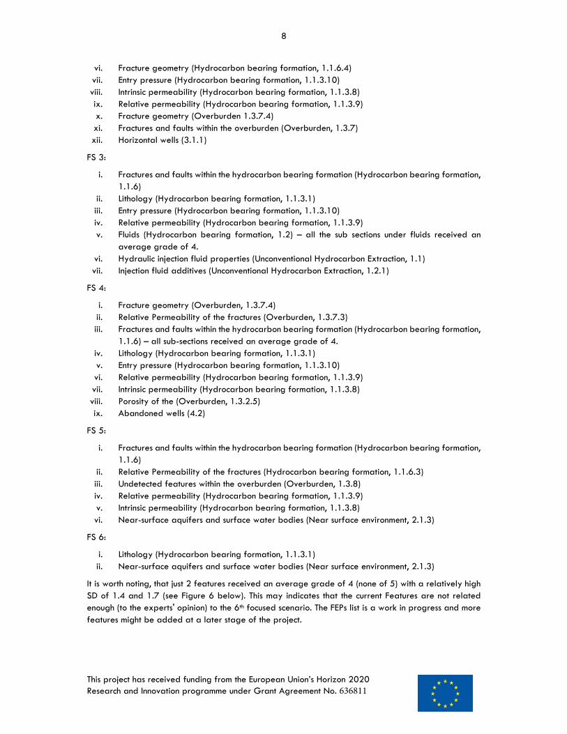
FS 5:
i. Fractures and faults within the hydrocarbon bearing formation (Hydrocarbon bearing formation,1.1.6)
ii. Relative Permeability of the fractures (Hydrocarbon bearing formation, 1.1.6.3)iii. Undetected features within the overburden (Overburden, 1.3.8)iv. Relative permeability (Hydrocarbon bearing formation, 1.1.3.9)v. Intrinsic permeability (Hydrocarbon bearing formation, 1.1.3.8)vi. Near-surface aquifers and surface water bodies (Near surface environment, 2.1.3)
FS 6:
i. Lithology (Hydrocarbon bearing formation, 1.1.3.1)ii. Near-surface aquifers and surface water bodies (Near surface environment, 2.1.3)
It is worth noting, that just 2 features received an average grade of 4 (none of 5) with a relatively high SD of 1.4 and 1.7 (see Figure 6 below). This may indicates that the current Features are not related enough (to the experts' opinion) to the 6th focused scenario. The FEPs list is a work in progress and more features might be added at a later stage of the project.

9
This project has received funding from the European Union’s Horizon 2020 Research and Innovation programme under Grant Agreement No. 636811
Figure 1 - Correlation between a feature's average grade and STDEV., FS1
Figure 2 - Correlation between a feature's average grade and STDEV., FS2
0.5
1.0
1.5
2.0
1
2
3
4
5
Rock
/ Pe
troph
ysica
l pro
perti
esof
the
hydr
ocar
bon
bear
ing
form
atio
n
Lith
olog
y, H
ydro
carb
onbe
arin
g fo
rmat
ion
Intri
nsic
perm
eabi
lity,
Hydr
ocar
bon
bear
ing
form
atio
n
Stre
ss a
nd M
echa
nica
lpr
oper
ties,
Hyd
roca
rbon
bear
ing
form
atio
n
Frac
ture
s an
d fa
ults
with
in th
ehy
droc
arbo
n be
arin
g fo
rmat
ion
Hete
roge
neity
of t
hehy
droc
arbo
n be
arin
g fo
rmat
ion
Intri
nsic
perm
eabi
lity
of th
efra
ctur
e, H
ydro
carb
on b
earin
gfo
rmat
ion
Horiz
onta
l wel
ls
Wel
l orie
ntat
ion
STDE
V.
Aver
age
grad
e
Average STDEV
0.5
1.0
1.5
2.0
1
2
3
4
5
Rock
/ Pe
troph
ysica
l pro
perti
es o
fth
e hy
droc
arbo
n be
arin
g fo
rmat
ion
Lith
olog
y, H
ydro
carb
on b
earin
gfo
rmat
ion
Intri
nsic
perm
eabi
lity,
Hyd
roca
rbon
bear
ing
form
atio
n
Rela
tive
perm
eabi
lity
Entry
pre
ssur
e
Frac
ture
s an
d fa
ults
with
in th
ehy
droc
arbo
n be
arin
g fo
rmat
ion
Intri
nsic
perm
eabi
lity
of th
efra
ctur
e, H
ydro
carb
on b
earin
g…
Rela
tive
Perm
eabi
lity
of th
efra
ctur
es
Frac
ture
geo
met
ry
Frac
ture
s an
d fa
ults
with
in th
eov
erbu
rden
Frac
ture
geo
met
ry
Horiz
onta
l wel
ls
STDE
V.
Aver
age
grad
e
Average STDEV

10
This project has received funding from the European Union’s Horizon 2020 Research and Innovation programme under Grant Agreement No. 636811
Figure 3 - Correlation between a feature's average grade and STDEV., FS3
Figure 4 - Correlation between a feature's average grade and STDEV., FS4
0.5
1.0
1.5
2.0
1
2
3
4
5
Lith
olog
y, H
ydro
carb
on b
earin
gfo
rmat
ion
Intri
nsic
perm
eabi
lity,
Hyd
roca
rbon
bear
ing
form
atio
n
Rela
tive
perm
eabi
lity
Entry
pre
ssur
e
Frac
ture
s an
d fa
ults
with
in th
ehy
droc
arbo
n be
arin
g fo
rmat
ion
Poro
sity
of th
e fra
ctur
e
Intri
nsic
perm
eabi
lity
of th
e fra
ctur
e,Hy
droc
arbo
n be
arin
g fo
rmat
ion
Rela
tive
Perm
eabi
lity
of th
e fra
ctur
es
Frac
ture
geo
met
ry
Poro
sity
Rela
tive
Perm
eabi
lity
of th
e fra
ctur
es
Frac
ture
geo
met
ry
Aban
done
d w
ells
STDE
V.
Aver
age
grad
e
Average STDEV
0.5
1.0
1.5
2.0
1
2
3
4
5
Lith
olog
y, H
ydro
carb
on b
earin
gfo
rmat
ion
Rela
tive
perm
eabi
lity
Entry
pre
ssur
e
Frac
ture
s an
d fa
ults
with
in th
ehy
droc
arbo
n be
arin
g fo
rmat
ion
Hydr
ocar
bons
Natu
ral f
orm
atio
n w
ater
Prod
uctio
n flu
ids
Pore
flui
d co
mpo
sitio
n w
ithin
the
frack
ing
rese
rvoi
r
Rese
rvoi
r flu
ids
Othe
r flu
ids
Hydr
aulic
inje
ctio
n flu
id p
rope
rties
Inje
ctio
n flu
id a
dditi
ves
STDE
V.
Aver
age
grad
e
Average STDEV

11
This project has received funding from the European Union’s Horizon 2020 Research and Innovation programme under Grant Agreement No. 636811
Figure 5 - Correlation between a feature's average grade and STDEV., FS5
Figure 6 - Correlation between a feature's average grade and STDEV., FS6
0.5
1.0
1.5
2.0
1
2
3
4
5
Lith
olog
y, H
ydro
carb
onbe
arin
g fo
rmat
ion
Near
-sur
face
aqu
ifers
and
surfa
ce w
ater
bod
ies
STDE
V.
Aver
age
grad
e
Average STDEV
0.5
1.0
1.5
2.0
1
2
3
4
5
Intri
nsic
perm
eabi
lity,
Hydr
ocar
bon
bear
ing
form
atio
n
Rela
tive
perm
eabi
lity
Frac
ture
s an
d fa
ults
with
in th
ehy
droc
arbo
n be
arin
gfo
rmat
ion
Rela
tive
Perm
eabi
lity
of th
efra
ctur
es
Unde
tect
ed fe
atur
es w
ithin
the
over
burd
en
Near
-sur
face
aqu
ifers
and
surfa
ce w
ater
bod
ies
STDE
V.
Aver
age
grad
e
Average STDEV

12
This project has received funding from the European Union’s Horizon 2020 Research and Innovation programme under Grant Agreement No. 636811
2.1.2 Highest ranked Events The highest ranked Events are very similar for all 6 focused scenarios, as can be seen in the lists below.
FS 1:
i. Hydraulic fracturing (Operational events, 1.5)ii. Earthquakes (Natural events, 2.1)iii. Overpressuring (Accidents and unplanned events, 3.2)
FS 2:
i. Hydraulic fracturing (Operational events, 1.5)ii. Overpressuring (Accidents and unplanned events, 3.2)iii. Production (Operational events, 1.7)iv. Seal failure (Operational events, 1.9)v. Cap rock failure (Natural events, 2.4)vi. Poor site characterization (Accidents and unplanned events, 3.3)vii. Cementation poorly undertaken (Accidents and unplanned events, 3.5)
FS 3:
i. Hydraulic fracturing (Operational events, 1.5)ii. Overpressuring (Accidents and unplanned events, 3.2)iii. Production (Operational events, 1.7)iv. Poor site characterization (Accidents and unplanned events, 3.3)v. Cementation poorly undertaken (Accidents and unplanned events, 3.5)vi. Incorrect chemical mix released into fracking fluid (Accidents and unplanned events, 3.4)
FS 4:
i. Hydraulic fracturing (Operational events, 1.5)ii. Overpressuring (Accidents and unplanned events, 3.2)iii. Production (Operational events, 1.7)iv. Poor site characterization (Accidents and unplanned events, 3.3)v. Cap rock failure (Natural events, 2.4)vi. Seal failure (Operational events, 1.9)vii. Out of zone / beyond pumping (Operational events, 1.5)viii. Cementation poorly undertaken (Accidents and unplanned events, 3.5)
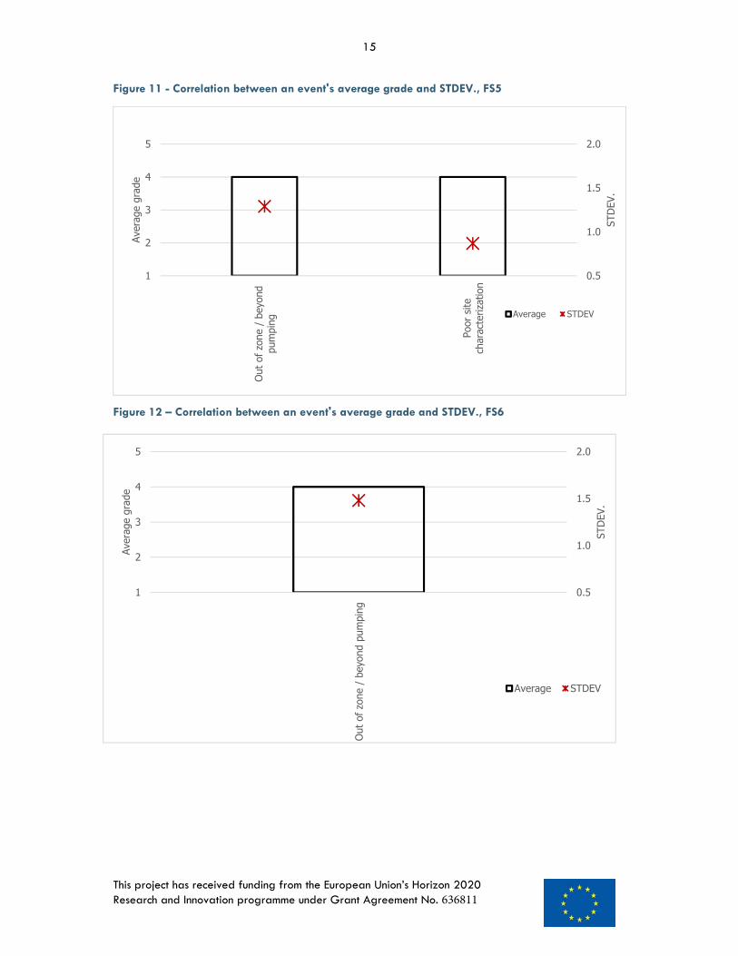
FS 5:
i. Poor site characterization (Accidents and unplanned events, 3.3)ii. Out of zone / beyond pumping (Operational events, 1.5)
FS 6:
i. Out of zone / beyond pumping (Operational events, 1.5)

13
This project has received funding from the European Union’s Horizon 2020 Research and Innovation programme under Grant Agreement No. 636811
Figure 7 – Correlation between an event's average grade and STDEV., FS1
Figure 8 - Correlation between an event's average grade and STDEV., FS2
0.5
1.0
1.5
2.0
1
2
3
4
5
Hydr
aulic
frac
turin
g
Earth
quak
es
Over
pres
surin
g
STDE
V.
Aver
age
grad
e
Average STDEV
0.5
1.0
1.5
2.0
1
2
3
4
5
Hydr
aulic
frac
turin
g
Prod
uctio
n
Seal
failu
re
Cap
rock
failu
re
Over
pres
surin
g
Poor
site
cha
ract
eriza
tion
Cem
enta
tion
poor
ly u
nder
take
n(s
pace
s le
ft)
STDE
V.
Aver
age
grad
e
Average STDEV

14
This project has received funding from the European Union’s Horizon 2020 Research and Innovation programme under Grant Agreement No. 636811
Figure 9 – Correlation between an event's average grade and STDEV., FS3
Figure 10 – Correlation between an event's average grade and STDEV., FS4
0.5
1.0
1.5
2.0
1
2
3
4
5
Hydr
aulic
frac
turin
g
Prod
uctio
n
Over
pres
surin
g
Poor
site
cha
ract
eriza
tion
Inco
rrect
che
mica
l mix
rele
ased
into
frac
king
fluid
Cem
enta
tion
poor
lyun
derta
ken
(spa
ces
left)
STDE
V.
Aver
age
grad
e
Average STDEV
0.5
1.0
1.5
2.0
1
2
3
4
5
Hydr
aulic
frac
turin
g
Out o
f zon
e / b
eyon
dpu
mpi
ng Prod
uctio
n
Seal
failu
re
Cap
rock
failu
re
Over
pres
surin
g
Poor
site
cha
ract
eriza
tion
Cem
enta
tion
poor
lyun
derta
ken
(spa
ces
left)
STDE
V.
Aver
age
grad
e
Average STDEV
15
This project has received funding from the European Union’s Horizon 2020 Research and Innovation programme under Grant Agreement No. 636811
Figure 11 - Correlation between an event's average grade and STDEV., FS5
Figure 12 – Correlation between an event's average grade and STDEV., FS6
0.5
1.0
1.5
2.0
1
2
3
4
5
Out o
f zon
e / b
eyon
dpu
mpi
ng
Poor
site
char
acte
rizat
ion
STDE
V.
Aver
age
grad
e
Average STDEV
0.5
1.0
1.5
2.0
1
2
3
4
5
Out o
f zon
e / b
eyon
d pu
mpi
ng
STDE
V.
Aver
age
grad
e
Average STDEV

16
This project has received funding from the European Union’s Horizon 2020 Research and Innovation programme under Grant Agreement No. 636811
2.1.3 Highest ranked Processes As with the Events, the highest ranked Processes are very similar between the six focused cenarios.
FS 1:
i. Fluid pressure exceeds rock fracking pressures generating new fractures (Hydraulics / FluidPressure Dominated, 2.1)
ii. Fluid exceeds fault sealing pressures (Hydraulics / Fluid Pressure Dominated, 2.2)iii. Fluid pressure exceeds stability of part of the plant construction (Hydraulics / Fluid Pressure
Dominated, 2.3)iv. Soil and rock deformation around boreholes (Mechanical, 4.1)v. Propagation of fractures beyond the target zone (Mechanical, 4.2)vi. Fluid exceeds fault sealing pressures (Mechanical, 4.3)vii. Fault valving (Mechanical, 4.4)
FS 2:
i. Fluid pressure exceeds rock fracking pressures generating new fractures (Hydraulics / FluidPressure Dominated, 2.1)
ii. Fluid exceeds fault sealing pressures (Hydraulics / Fluid Pressure Dominated, 2.2)iii. Fluid pressure exceeds stability of part of the plant construction (Hydraulics / Fluid Pressure
Dominated, 2.3)iv. Soil and rock deformation around boreholes (Mechanical, 4.1)v. Propagation of fractures beyond the target zone (Mechanical, 4.2)vi. Fluid exceeds fault sealing pressures (Mechanical, 4.3)vii. Fault valving (Mechanical, 4.4)viii. Displacement of surrounding formation fluids (Hydraulics / Fluid Pressure Dominated, 2.4)ix. Buoyancy-driven flow (Hydraulics / Fluid Pressure Dominated, 2.5)x. Micro-cracking in the casing cements (Mechanical, 4.6)
FS 3:
i. Propagation of fractures beyond the target zone (Mechanical, 4.2)ii. Advection (Hydraulics / Fluid Pressure Dominated, 2.8.1)iii. Diffusion (Hydraulics / Fluid Pressure Dominated, 2.8.3)iv. Hydraulic and production fluids and the associated contaminants release processes (Hydraulics
/ Fluid Pressure Dominated, 2.9)v. Corrosive mixture attacks plant (Chemical, 3.1)vi. Corrosive mixture attacks geology (Chemical, 3.2)vii. Mineral dissolution (Chemical, 3.4)viii. Advection and co-migration of other gas (Hydraulics / Fluid Pressure Dominated, 2.6)ix. Water mediated transport (Hydraulics / Fluid Pressure Dominated, 2.8)x. Sorption and desorption (Chemical, 3.3)xi. Heavy metal release (Chemical, 3.5)
FS 4:
i. Propagation of fractures beyond the target zone (Mechanical, 4.2)ii. Fluid exceeds fault sealing pressures (4.3)iii. Advection (Hydraulics / Fluid Pressure Dominated, 2.8.1)iv. Hydraulic and production fluids and the associated contaminants release processes (Hydraulics
/ Fluid Pressure Dominated, 2.9)v. Mineral dissolution (Chemical, 3.4)vi. Heavy metal release (Chemical, 3.5)

17
This project has received funding from the European Union’s Horizon 2020 Research and Innovation programme under Grant Agreement No. 636811
vii. Fluid pressure exceeds rock fracking pressures generating new fractures (Hydraulics / FluidPressure Dominated, 2.1)
viii. Fluid exceeds fault sealing pressures (Hydraulics / Fluid Pressure Dominated, 2.2)ix. Fault valving (Mechanical, 4.4)x. Displacement of surrounding formation fluids (Hydraulics / Fluid Pressure Dominated, 2.4)xi. Buoyancy-driven flow (Hydraulics / Fluid Pressure Dominated, 2.5)xii. Micro-cracking in the casing cements (Mechanical, 4.6)xiii. Dispersion (Hydraulics / Fluid Pressure Dominated, 2.8.2)xiv. Soil and rock deformation around boreholes (Mechanical, 4.1)
FS 5:
i. Advection (Hydraulics / Fluid Pressure Dominated, 2.8.1)ii. Hydraulic and production fluids and the associated contaminants release processes (Hydraulics
/ Fluid Pressure Dominated, 2.9)iii. Displacement of surrounding formation fluids (Hydraulics / Fluid Pressure Dominated, 2.4)iv. Buoyancy-driven flow (Hydraulics / Fluid Pressure Dominated, 2.5)v. Dispersion (Hydraulics / Fluid Pressure Dominated, 2.8.2)vi. Water mediated transport (Hydraulics / Fluid Pressure Dominated, 2.8)
FS 6:
i. Advection (Hydraulics / Fluid Pressure Dominated, 2.8.1)ii. Hydraulic and production fluids and the associated contaminants release processes (Hydraulics
/ Fluid Pressure Dominated, 2.9)iii. Buoyancy-driven flow (Hydraulics / Fluid Pressure Dominated, 2.5)iv. Dispersion (Hydraulics / Fluid Pressure Dominated, 2.8.2)v. Diffusion (Hydraulics / Fluid Pressure Dominated, 2.8.3)
18
This project has received funding from the European Union’s Horizon 2020 Research and Innovation programme under Grant Agreement No. 636811
Figure 13 - Correlation between a process' average grade and STDEV., FS1
Figure 14 - Correlation between a process' average grade and STDEV., FS2
0.5
1.0
1.5
2.0
1
2
3
4
5
Flui
d pr
essu
re e
xcee
ds ro
ckfra
ckin
g pr
essu
res
gene
ratin
gne
w fr
actu
res
Flui
d ex
ceed
s fa
ult s
ealin
gpr
essu
res
Flui
d pr
essu
re e
xcee
dsst
abilit
y of
par
t of t
he p
lant
cons
truct
ion.
Disp
lace
men
t of s
urro
undi
ngfo
rmat
ion
fluid
s
Buoy
ancy
-driv
en fl
ow
Soil
and
rock
def
orm
atio
nar
ound
bor
ehol
es
Prop
agat
ion
of fr
actu
res
beyo
nd th
e ta
rget
zon
e
Flui
d ex
ceed
s fa
ult s
ealin
gpr
essu
res
Faul
t val
ving
Micr
o-cr
acki
ng in
the
casin
gce
men
ts
STDE
V.
Aver
age
grad
e
Average STDEV
0.5
1.0
1.5
2.0
1
2
3
4
5
Flui
d pr
essu
re e
xcee
ds ro
ckfra
ckin
g pr
essu
res
gene
ratin
g ne
w fr
actu
res
Flui
d ex
ceed
s fa
ult s
ealin
gpr
essu
res
Flui
d pr
essu
re e
xcee
dsst
abilit
y of
par
t of t
he p
lant
cons
truct
ion.
Soil
and
rock
def
orm
atio
nar
ound
bor
ehol
es
Prop
agat
ion
of fr
actu
res
beyo
nd th
e ta
rget
zon
e
Flui
d ex
ceed
s fa
ult s
ealin
gpr
essu
res
Faul
t val
ving
STDE
V.
Aver
age
grad
e
Average STDEV
19
This project has received funding from the European Union’s Horizon 2020 Research and Innovation programme under Grant Agreement No. 636811
Figure 15 - Correlation between a process' average grade and STDEV., FS3
Figure 16 – Correlation between a process' average grade and STDEV., FS4
0.5
1.0
1.5
2.0
1
2
3
4
5
Flui
d pr
essu
re e
xcee
ds ro
ckfra
ckin
g pr
essu
res
gene
ratin
g…Fl
uid
exce
eds
faul
t sea
ling
pres
sure
sDi
spla
cem
ent o
f sur
roun
ding
form
atio
n flu
ids
Buoy
ancy
-driv
en fl
ow
Adve
ctio
n
Disp
ersio
n
Hydr
aulic
and
pro
duct
ion
fluid
san
d th
e as
socia
ted…
Min
eral
diss
olut
ion
Heav
y m
etal
rele
ase
Soil
and
rock
def
orm
atio
nar
ound
bor
ehol
esPr
opag
atio
n of
frac
ture
s be
yond
the
targ
et z
one
Flui
d ex
ceed
s fa
ult s
ealin
gpr
essu
res
Faul
t val
ving
Micr
o-cr
acki
ng in
the
casin
gce
men
ts
STDE
V.
Aver
age
grad
e
Average STDEV
0.5
1.0
1.5
2.0
1
2
3
4
5
Adve
ctio
n an
d co
-mig
ratio
n of
oth
erga
s
Wat
er m
edia
ted
trans
port
Adve
ctio
n
Diffu
sion
Hydr
aulic
and
pro
duct
ion
fluid
s an
dth
e as
socia
ted
cont
amin
ants
rele
ase
proc
esse
s
Corro
sive
mixt
ure
atta
cks
plan
t
Corro
sive
mixt
ure
atta
cks
geol
ogy
Sorp
tion
and
deso
rptio
n
Min
eral
diss
olut
ion
Heav
y m
etal
rele
ase
Prop
agat
ion
of fr
actu
res
beyo
nd th
eta
rget
zon
e
STDE
V.
Aver
age
grad
e
Average STDEV

20
This project has received funding from the European Union’s Horizon 2020 Research and Innovation programme under Grant Agreement No. 636811
Figure 17 – Correlation between a process' average grade and STDEV., FS5
Figure 18 – Correlation between a process' average grade and STDEV., FS6
0.5
1.0
1.5
2.0
1
2
3
4
5
Disp
lace
men
t of s
urro
undi
ngfo
rmat
ion
fluid
s
Buoy
ancy
-driv
en fl
ow
Wat
er m
edia
ted
trans
port
Adve
ctio
n
Disp
ersio
n
Hydr
aulic
and
pro
duct
ion
fluid
san
d th
e as
socia
ted
cont
amin
ants
rele
ase
proc
esse
s
STDE
V.
Aver
age
grad
e
Average STDEV
0.5
1.0
1.5
2.0
1
2
3
4
5
Buoy
ancy
-driv
en fl
ow
Adve
ctio
n
Disp
ersio
n
Diffu
sion
Hydr
aulic
and
pro
duct
ion
fluid
s an
d th
e as
socia
ted
cont
amin
ants
rele
ase
proc
esse
s
STDE
V.
Aver
age
grad
e
Average STDEV

1 Least Critical
2
3
4
5 Most Critical
List of FeaturesA. Features of the Natural System 1 Hydrogeology S1 S2 S3 S4 S5 S61.1. Hydrocarbon bearing formation (Source)1.1.1. Type of the hydrocarbon bearing formation 3 3 3 2 2 21.1.2. Geometry of the hydrocarbon bearing formation 3 3 2 2 2 21.1.2.1 Thickness 3 3 2 2 2 21.1.3. Rock / Petrophysical properties of the hydrocarbon bearing formation 4 4 3 3 3 31.1.3.1 Lithology 4 4 4 4 3 41.1.3.2 Diagenesis 2 2 3 3 3 21.1.3.3 Pore architecture 2 3 3 2 2 21.1.3.4 Mineralogy 2 2 3 2 3 31.1.3.5 Kerogen type 2 2 3 2 3 21.1.3.6 Thermal maturation of source rock 1 1 2 2 2 21.1.3.7 Porosity 3 3 3 2 3 31.1.3.8 Intrinsic permeability 4 4 3 4 4 31.1.3.9 Relative permeability 3 4 4 5 4 31.1.3.10 Entry pressure 3 4 4 4 3 31.1.3.11 Residual saturation 2 2 2 1 1 21.1.3.12 Hysteresis 2 1 1 1 2 11.1.4. Stress and Mechanical properties 5 3 1 2 2 21.1.5. Heterogeneity of the hydrocarbon bearing formation 4 3 3 3 3 31.1.6. Fractures and faults within the hydrocarbon bearing formation 4 4 4 5 4 31.1.6.1 Porosity of the fracture 3 3 3 4 3 21.1.6.2 Intrinsic permeability of the fracture 4 4 3 4 3 21.1.6.3 Relative Permeability of the fractures 3 4 3 4 4 21.1.6.4 Fracture geometry 3 4 3 4 3 21.1.7. Undetected features within the hydrocarbon bearing formation 2 3 3 3 3 21.1.8. Vertical geothermal gradient of the hydrocarbon bearing formation 1 2 3 2 2 21.1.9. Formation pressure of the hydrocarbon bearing formation 3 3 3 3 2 21.2. Fluids1.2.1. Hydrocarbons 2 2 4 2 3 31.2.2. Natural formation water 2 2 4 2 2 21.2.3. Production fluids 2 3 4 2 2 21.2.4. Pore fluid composition within the fracking reservoir 2 3 4 2 3 21.2.5. Reservoir fluids 2 2 4 2 2 21.2.6. Other fluids 2 2 4 2 2 2
Relevance to Scenario

S1 S2 S3 S4 S5 S61.3. Overburden1.3.1. Geometry of the overburden 3 2 2 2 2 31.3.1.1 Thickness 3 3 2 2 3 31.3.2. Rock / Petrophysical properties of the overburden 3 2 2 2 2 31.3.2.1 Lithology 2 2 3 3 3 31.3.2.2 Diagenesis 2 1 3 3 3 21.3.2.3 Pore architecture 1 2 3 2 3 21.3.2.4 Mineralogy 1 1 3 2 2 21.3.2.5 Porosity 3 2 2 4 3 31.3.2.6 Intrinsic permeability 2 3 2 3 3 31.3.2.7 Relative permeability 2 2 2 3 3 31.3.2.8 Entry pressure 2 2 2 2 2 21.3.2.9 Residual saturation 1 2 1 2 2 21.3.2.10 Hysteresis 1 1 1 2 2 21.3.3. Free gas pocket within the overburden 2 2 2 2 2 21.3.4. Additional seals within the overburden 1 2 1 2 2 31.3.5. Unconformities within the overburden 2 3 2 2 2 21.3.6. Heterogeneity within the overburden 2 3 2 2 2 21.3.7. Fractures and faults within the overburden 3 4 3 3 3 31.3.7.1 Porosity of the fracture 2 2 3 3 3 31.3.7.2 Intrinsic permeability of the fracture 2 3 3 3 3 21.3.7.3 Relative Permeability of the fractures 2 3 3 4 3 21.3.7.4 Fracture geometry 2 4 3 4 3 21.3.8. Undetected features within the overburden 2 2 3 3 4 31.3.9. Vertical geothermal gradient of the overburden 2 2 2 2 3 21.3.10. Formation "overburden" pressure 2 3 3 2 3 21.3.11. Overburden pressure 2 2 2 3 2 21.4. Underburden1.4.1. Geometry of the underburden 2 2 1 1 2 11.4.1.1 Thickness 2 2 1 1 1 21.4.2. Rock / Petrophysical properties of the underburden 2 2 2 2 2 21.4.2.1 Lithology 2 2 2 3 2 21.4.2.2 Diagenesis 2 2 2 2 2 11.4.2.3 Pore architecture 1 2 2 2 2 21.4.2.4 Mineralogy 1 2 2 2 2 21.4.2.5 Porosity 2 2 2 2 2 21.4.2.6 Intrinsic permeability 2 2 2 2 2 11.4.2.7 Relative permeability 2 2 2 2 2 11.4.2.8 Entry pressure 1 2 1 2 2 11.4.2.9 Residual saturation 1 2 2 2 2 11.4.2.10 Hysteresis 1 2 2 2 1 11.4.3. Unconformities within the underburden 1 2 2 2 2 21.4.4. Heterogeneity within the underburden 2 2 2 2 2 21.4.5. Fractures and faults within the underburden 2 2 2 2 2 21.4.6. Undetected features within the underburden 2 2 2 2 2 21.4.7. Vertical geothermal gradient within the underburden 2 2 2 2 2 21.4.8. Formation "underburden" pressure 2 2 2 2 2 2
2 Near surface environment (Receptors)2.1. Terrestrial environment2.1.1. Geographical location 2 1 2 3 3 22.1.2. Soils and sediments 2 2 2 3 3 32.1.3. Near-surface aquifers and surface water bodies 2 2 3 3 4 42.1.4. Terrestrial flora and fauna 1 1 2 2 2 22.1.5. Terrestrial ecological systems 1 2 2 2 2 22.1.6. Buildings 2 2 2 2 2 22.2. Marine environment 2.2.1. Local oceanography 2 2 2 2 1 22.2.2. Marine sediments 2 2 2 2 2 22.2.3. Marine Stratification and Mixing 2 2 2 2 2 22.2.4. Marine flora and fauna 1 1 1 2 2 22.2.5. Marine ecological systems 1 1 2 2 1 2

S1 S2 S3 S4 S5 S62.3. Human Environment2.3.1. Human characteristics 2 1 2 1 2 22.3.2. Diet and food processing 1 1 1 2 2 22.3.3. Lifestyles 1 2 1 2 2 12.3.4. Land and water use 2 1 2 2 2 22.3.5. Community characteristics 2 1 2 2 2 12.4. Atmosphere and meteorology
B. Unconventional Hydrocarbon Extraction 1 Hydro‐fracturing fluid1.1. Hydraulic injection fluid properties 3 3 4 2 3 21.2. Physical properties of injection fluid1.2.1. Injection fluid additives 3 2 4 3 3 31.2.2. Hydro-fracturing fluids interactions 3 2 3 2 2 2
2 Site development 2.1. Logistics above ground 2 2 2 1 2 12.2. Baseline monitoring 3 2 3 2 3 3
3 Site operation 3 2 5 1 2 4
3.1. Drilling and completion3.1.1. Horizontal wells 4 4 3 3 2 23.1.2. Formation damage 3 3 3 3 3 33.1.3. Well lining and completion 2 2 2 2 2 23.1.4. Workover 2 1 1 2 1 13.1.5. Monitoring wells 3 2 3 3 3 33.1.6. Well records 2 2 3 3 2 33.1.7. Well orientation 4 3 3 2 2 33.1.8. Well engineering 2 2 2 2 2 2
4 Site decommissioning 4.1. Closure and sealing of boreholes 2 3 3 3 3 34.2. Abandoned wells 2 2 3 4 3 3
1 Least Critical2345 Most Critical
List of EventsS1 S2 S3 S4 S5 S6
1 Operational Events1.1. Multiple well drilling from same platform 3 3 3 3 2 31.2. Initial drilling to given below water table (Open Hole) 3 3 3 3 3 31.2. Casing emplacement 3 3 3 3 2 31.2. Cementation with wiper plug 2 2 2 2 2 21.2. Drilling through wiper plug and casing shoe 2 3 2 2 3 31.2. Additional cementation 2 3 2 2 2 21.3. Logging Borehole 2 3 2 3 2 21.4. Drilling horizontal borehole 3 3 3 2 3 31.4. Casing horizontal borehole 2 3 3 3 3 31.4. Cementation 2 3 2 2 2 31.4. Perforation 3 3 2 3 2 21.5. Hydraulic fracturing 5 4 4 4 3 21.5. Out of zone / beyond pumping 3 3 3 4 4 41.6. Plugging & drilling out of plugs 2 2 2 2 2 21.7. Flow back 2 3 3 3 3 21.7. Production 3 4 4 4 3 31.8. Abandonment 2 3 3 3 3 31.9. Seal failure 3 4 3 4 3 3
2 Natural events2.1. Earthquakes 4 3 2 3 2 22.2. Large scale erosion 3 2 2 3 2 22.3. Hydrological and hydrogeological response to geological changes 2 3 3 3 3 32.4. Cap rock failure 3 4 3 4 3 32.5. Unexpected large scale scenario 2 3 3 3 2 2
3 Accidents and unplanned events 3.1. Surface chemical spills 2 2 3 3 2 23.2. Overpressuring 4 4 4 4 3 33.3. Poor site characterization 3 4 4 4 4 33.4. Incorrect chemical mix released into fracking fluid 3 3 4 3 2 33.5. Cementation poorly undertaken (spaces left) 3 4 4 4 3 33.6. Well lining too limited, open hole left 2 3 3 3 2 33.7. Inappropriate management of drill cuttings and spent drilling muds. 2 2 2 2 2 23.8. Unlikely significant event 2 3 3 3 2 2
Relevance to Scenario

1 Least Critical2345 Most Critical
List of ProcessesS1 S2 S3 S4 S5 S6
1 Thermal effects on the borehole 1.1. Thermal effects on borehole and seal integrity. 3 3 3 3 3 31.2. Thermal effects on the injection point 3 2 2 1 2 2
2 Hydraulics / Fluid Pressure Dominated2.1. Fluid pressure exceeds rock fracking pressures generating new fractures 4 4 3 4 3 22.2. Fluid exceeds fault sealing pressures 4 4 3 4 2 22.3. Fluid pressure exceeds stability of part of the plant construction. 4 4 2 3 3 22.4. Displacement of surrounding formation fluids 3 4 3 4 4 32.5. Buoyancy-driven flow 3 4 3 4 4 42.6. Advection and co-migration of other gas 2 3 4 3 3 32.7. Formation of Gas hydrates 3 3 3 2 2 32.8. Water mediated transport 2 3 4 3 4 32.8.1. Advection 3 3 4 4 4 42.8.2. Dispersion 3 3 3 4 4 42.8.3. Diffusion 3 3 4 3 3 42.9. Hydraulic and production fluids and the associated contaminants release processes 3 3 4 4 4 4
3 Chemical3.1 Corrosive mixture attacks plant 3 3 4 3 2 23.2 Corrosive mixture attacks geology 3 3 4 3 3 33.3 Sorption and desorption 2 3 4 3 3 33.4 Mineral dissolution 3 3 4 4 3 33.5 Heavy metal release 2 3 4 4 3 3
4 Mechanical4.1 Soil and rock deformation around boreholes 4 4 2 4 2 34.1.1 Subsidence of ground related to gas extraction 3 3 3 3 3 34.2 Propagation of fractures beyond the target zone 4 4 4 5 3 34.3 Fluid exceeds fault sealing pressures 4 4 3 5 3 34.4 Fault valving 4 4 3 4 3 24.5 Generation of excavation disturbed zone around well 3 3 3 3 2 24.6 Micro-cracking in the casing cements 3 4 3 4 3 3
Relevance to Scenario

26
This project has received funding from the European Union’s Horizon 2020 Research and Innovation programme under Grant Agreement No. 636811
References Krosnick, J.A. and Fabrigar L.R. (1997) "Designing rating scales for effective measurement in surveys". In: (L. Lyberg, P. Biemer, M. Collins, E. de Leeuw, C. Dippo, N. Schwarz and D. Trewin, eds.) Survey measurement and process quality. John Wiley and Sons, Inc., New York, NY. pp. 141–164.
Maitland Aaron (2009) "How many scale points should I include for attitudinal questions?" Survey Practice. 2 (5)
Oldendick Robert W (2008) "Ranking" In: (Paul J. Lavrakas (Ed.), Encyclopedia of Survey Research Methods. Thousand Oaks, CA: Sage Publications, Inc. pp. 689-690.

27
This project has received funding from the European Union’s Horizon 2020 Research and Innovation programme under Grant Agreement No. 636811
Appendix A – FEP appraisal tables from members of the project
The full appraisal tables are attached to this deliverable as Excel files.

FracRisk
Reporting form for deliverables
Deliverable Number: D4.1
Work package number: 4
Deliverable title Ranked FEP list , Data Tables
Type Report
Dissemination Level PU
Lead participant EWRE
Contributing scientists and other personnel Hagit Wiener, Yoni Goren, Jacob Bensabat, Alexandru Tatomir, Katriona Edlmann, Christopher McDermott With data provided by most participants of the FracRisk project (www.fracrisk.eu).
Schedules delivery date from DOW 1/12/2015
Actual / forecast delivery data 6/01/2016
Comments (optional) Click here to enter text.
Deliverable summary text:
FEP Appraisal data tables, raw data
The following tables have been anonymised as at this stage of the analysis the person // institution presenting the table is not of relevance.
Submitted 06/01/2016
Reviewed Click here to enter text.
Final submission Click here to enter text.

1 Least Critical
2
3
4
5 Most Critical
List of FeaturesOverall Importance
In Risk Analysis
1 Hydrogeology S1 S2 S3 S4 S5 S6
1.1. Hydrocarbon bearing formation (Source)1.1.1. Type of the hydrocarbon bearing formation 3 3 2 2 2 1 1
1.1.2. Geometry of the hydrocarbon bearing formation 2 2 2 2 2 2 2
1.1.2.1 Thickness 4 4 4 4 2 2 2
1.1.3. Rock / Petrophysical properties of the hydrocarbon bearing formation 4 4 4 4 3 4 4
1.1.3.1 Lithology 4 4 4 4 4 4 4
1.1.3.2 Diagenesis 3 3 3 3 3 3 3
1.1.3.3 Pore architecture 1 1 1 1 1 1 1
1.1.3.4 Mineralogy 3 1 1 3 1 1 3
1.1.3.5 Kerogen type 2 1 1 2 1 2 2
1.1.3.6 Thermal maturation of source rock 1 1 1 1 1 1 1
1.1.3.7 Porosity 4 2 2 4 3 3 3
1.1.3.8 Intrinsic permeability 4 4 4 4 4 4 4
1.1.3.9 Relative permeability 4 4 4 4 4 3 3
1.1.3.10 Entry pressure 5 4 5 5 5 3 3
1.1.3.11 Residual saturation 2 2 1 1 1 1 1
1.1.3.12 Hysteresis 2 2 1 1 1 1 1
1.1.4. Stress and Mechanical properties 5 5 1 1 1 3 3
1.1.5. Heterogeneity of the hydrocarbon bearing formation 5 3 4 4 5 4 4
1.1.6. Fractures and faults within the hydrocarbon bearing formation 4 4 4 4 4 2 2
1.1.6.1 Porosity of the fracture 4 2 2 4 4 2 2
1.1.6.2 Intrinsic permeability of the fracture 4 4 4 4 4 4 4
1.1.6.3 Relative Permeability of the fractures 4 4 4 4 4 3 3
1.1.6.4 Fracture geometry 4 4 4 4 4 2 2
1.1.7. Undetected features within the hydrocarbon bearing formation 2 2 2 2 2 2 2
1.1.8. Vertical geothermal gradient of the hydrocarbon bearing formation 3 1 1 1 1 3 3
1.1.9. Formation pressure of the hydrocarbon bearing formation 3 3 3 3 3 2 2
1.2. Fluids1.2.1. Hydrocarbons 2 2 2 2 1 1 1
1.2.2. Natural formation water 2 2 2 2 1 2 2
1.2.3. Production fluids 2 2 2 2 1 1 1
1.2.4. Pore fluid composition within the fracking reservoir 2 2 2 2 1 1 1
1.2.5. Reservoir fluids 2 2 2 2 2 2 2
1.2.6. Other fluids 2 2 2 2 2 2 2
1.3. Overburden1.3.1. Geometry of the overburden 4 4 1 3 1 3 3
1.3.1.1 Thickness 4 4 1 3 1 3 3
1.3.2. Rock / Petrophysical properties of the overburden 2 2 1 2 1 1 1
1.3.2.1 Lithology 2 2 1 2 2 2 2
1.3.2.2 Diagenesis 3 3 1 2 2 3 3
1.3.2.3 Pore architecture 1 1 1 1 1 1 1
1.3.2.4 Mineralogy 1 1 1 1 1 1 1
1.3.2.5 Porosity 2 2 2 2 2 2 2
1.3.2.6 Intrinsic permeability 2 2 2 2 2 2 2
1.3.2.7 Relative permeability 2 2 2 2 2 2 2
1.3.2.8 Entry pressure 1 1 1 1 1 1 1
1.3.2.9 Residual saturation 1 1 1 1 1 1 1
1.3.2.10 Hysteresis 1 1 1 1 1 1 1
1.3.3. Free gas pocket within the overburden 3 3 3 3 1 2 2
1.3.4. Additional seals within the overburden 1 1 1 1 1 1 1
1.3.5. Unconformities within the overburden 2 2 2 1 1 2 2
1.3.6. Heterogeneity within the overburden 2 2 2 2 2 2 2
1.3.7. Fractures and faults within the overburden 5 5 5 5 1 5 5
1.3.7.1 Porosity of the fracture 3 3 3 3 3 3 3
1.3.7.2 Intrinsic permeability of the fracture 2 2 2 2 2 2 2
1.3.7.3 Relative Permeability of the fractures 2 2 2 2 2 2 2
1.3.7.4 Fracture geometry 5 1 5 4 5 1 1
1.3.8. Undetected features within the overburden 4 1 2 4 2 1 1
1.3.9. Vertical geothermal gradient of the overburden 1 1 1 1 1 1 1
1.3.10. Formation "overburden" pressure 1 1 1 1 1 1 1
1.3.11. Overburden pressure 1 1 1 1 1 1 1
1.4. Underburden1.4.1. Geometry of the underburden 1 1 1 1 1 1 1
1.4.1.1 Thickness 1 1 1 1 1 1 1
1.4.2. Rock / Petrophysical properties of the underburden 2 2 2 2 2 2 2
1.4.2.1 Lithology 2 2 2 2 2 2 2
1.4.2.2 Diagenesis 1 1 1 1 1 1 1
1.4.2.3 Pore architecture 1 1 1 1 1 1 1
1.4.2.4 Mineralogy 2 2 2 2 2 2 2
1.4.2.5 Porosity 1 1 1 1 1 1 1
1.4.2.6 Intrinsic permeability 1 1 1 1 1 1 1
1.4.2.7 Relative permeability 1 1 1 1 1 1 1
1.4.2.8 Entry pressure 1 1 1 1 1 1 1
1.4.2.9 Residual saturation 1 1 1 1 1 1 1
1.4.2.10 Hysteresis 1 1 1 1 1 1 1
1.4.3. Unconformities within the underburden 1 1 1 1 1 1 1
1.4.4. Heterogeneity within the underburden 1 1 1 1 1 1 1
1.4.5. Fractures and faults within the underburden 1 1 1 1 1 1 1
1.4.6. Undetected features within the underburden 1 1 1 1 1 1 1
1.4.7. Vertical geothermal gradient within the underburden 2 2 2 2 2 2 2
1.4.8. Formation "underburden" pressure 1 1 1 1 1 1 1
2 Near surface environment (Receptors)2.1. Terrestrial environment2.1.1. Geographical location 3 1 1 1 1 3 3
2.1.2. Soils and sediments 4 1 1 1 3 4 4
2.1.3. Near‐surface aquifers and surface water bodies 4 3 2 1 1 4 4
2.1.4. Terrestrial flora and fauna 1 1 1 1 1 1 1
2.1.5. Terrestrial ecological systems 1 1 1 1 1 1 1
2.1.6. Buildings 1 1 1 1 1 1 1
2.2. Marine environment 2.2.1. Local oceanography 1 1 1 1 1 1 1
2.2.2. Marine sediments 1 1 1 1 1 1 1
2.2.3. Marine Stratification and Mixing 1 1 1 1 1 1 1
2.2.4. Marine flora and fauna 1 1 1 1 1 1 1
2.2.5. Marine ecological systems 1 1 1 1 1 1 1
2.3. Human Environment2.3.1. Human characteristics 1 1 1 1 1 1 1
2.3.2. Diet and food processing 1 1 1 1 1 1 1
2.3.3. Lifestyles 1 1 1 1 1 1 1
2.3.4. Land and water use 1 1 1 1 1 1 1
2.3.5. Community characteristics 1 1 1 1 1 1 1
2.4. Atmosphere and meteorology
1 Hydro‐fracturing fluid1.1. Hydraulic injection fluid properties 4 2 2 4 1 3 3
1.2. Physical properties of injection fluid1.2.1. Injection fluid additives 4 2 2 4 1 3 3
1.2.2. Hydro‐fracturing fluids interactions 1 1 1 1 1 1 1
2 Site development 2.1. Logistics above ground 1 1 1 1 1 1 1
2.2. Baseline monitoring 3 1 1 1 1 3 3
3 Site operation 3.1. Drilling and completion3.1.1. Horizontal wells 5 5 5 5 5 1 1
3.1.2. Formation damage 4 4 4 4 4 2 2
Relevance to ScenarioA. Features of the Natural System
B. Unconventional Hydrocarbon Extraction

1 Least Critical
2
3
4
5 Most Critical
Importance
List of ProcessesS1 S2 S3 S4 S5 S6
1 Thermal effects on the borehole 1.1. Thermal effects on borehole and seal integrity. 1 1 1 1 1 1 1
1.2. Thermal effects on the injection point 1 1 1 1 1 1 1
2 Hydraulics / Fluid Pressure Dominated2.1. Fluid pressure exceeds rock fracking pressures generating new fractures 5 5 5 5 5 3 3
2.2. Fluid exceeds fault sealing pressures 5 5 5 5 5 3 3
2.3. Fluid pressure exceeds stability of part of the plant construction. 5 5 5 5 5 3 3
2.4. Displacement of surrounding formation fluids 5 5 5 5 5 3 3
2.5. Buoyancy‐driven flow 5 5 5 5 5 3 3
2.6. Advection and co‐migration of other gas 2 1 2 2 2 2 2
2.7. Formation of Gas hydrates 1 1 1 1 1 1 1
2.8. Water mediated transport 3 1 2 2 2 3 3
2.8.1. Advection 3 1 2 2 2 3 3
2.8.2. Dispersion 3 1 2 2 2 3 3
2.8.3. Diffusion 3 1 2 2 2 3 3
2.9. Hydraulic and production fluids and the associated contaminants release processes 1 1 1 1 1 1 1
3 Chemical3.1 Corrosive mixture attacks plant 1 1 1 1 1 1 1
3.2 Corrosive mixture attacks geology 1 1 1 1 1 1 1
3.3 Sorption and desorption 1 1 1 1 1 1 1
3.4 Mineral dissolution 1 1 1 1 1 1 1
3.5 Heavy metal release 1 1 1 1 1 1 1
4 Mechanical4.1 Soil and rock deformation around boreholes 4 3 3 3 4 2 2
4.1.1 Subsidence of ground related to gas extraction 1 1 1 1 1 1 1
4.2 Propagation of fractures beyond the target zone 5 5 5 5 5 4 4
4.3 Fluid exceeds fault sealing pressures 5 5 5 5 5 4 4
4.4 Fault valving 2 1 1 1 2 1 1
4.5 Generation of excavation disturbed zone around well 1 1 1 1 1 1 1
4.6 Micro‐cracking in the casing cements 5 5 5 5 5 4 4
1 17 12 12 11 12 12
2 0 5 5 6 2 2
3 1 1 1 0 9 9
4 0 0 0 1 3 3
5 8 8 8 8 0 0
Relevance to Scenario

1 Least Critical
2
3
4
5 Most Critical
List of FeaturesOverall Importance
In Risk Analysis
1 Hydrogeology S1 S2 S3 S4 S5 S6
1.1. Hydrocarbon bearing formation (Source)1.1.1. Type of the hydrocarbon bearing formation 2 2 2 2 2 2 2
1.1.2. Geometry of the hydrocarbon bearing formation 3 2 2 3 3 3 3
1.1.2.1 Thickness 3 2 3 3 3 3 3
1.1.3. Rock / Petrophysical properties of the hydrocarbon bearing formation 3 2 2 3 3 3 3
1.1.3.1 Lithology 3 2 2 3 3 3 3
1.1.3.2 Diagenesis 1 1 1 1 1 1 1
1.1.3.3 Pore architecture 3 2 2 3 3 3 3
1.1.3.4 Mineralogy 3 2 2 3 3 3 3
1.1.3.5 Kerogen type 3 1 1 3 3 3 3
1.1.3.6 Thermal maturation of source rock 1 1 1 1 1 1 1
1.1.3.7 Porosity 5 4 5 5 5 5 5
1.1.3.8 Intrinsic permeability 5 4 5 5 5 5 5
1.1.3.9 Relative permeability 5 4 5 5 5 5 5
1.1.3.10 Entry pressure 5 5 3 4 4 4 4
1.1.3.11 Residual saturation 1 1 1 1 1 1 1
1.1.3.12 Hysteresis 1 1 1 1 1 1 1
1.1.4. Stress and Mechanical properties 5 5 5 5 5 5 5
1.1.5. Heterogeneity of the hydrocarbon bearing formation 3 2 3 3 3 3 3
1.1.6. Fractures and faults within the hydrocarbon bearing formation 5 5 5 5 5 5 5
1.1.6.1 Porosity of the fracture 5 4 5 5 5 5 5
1.1.6.2 Intrinsic permeability of the fracture 5 4 5 5 5 5 5
1.1.6.3 Relative Permeability of the fractures 5 3 5 5 5 5 5
1.1.6.4 Fracture geometry 5 5 5 5 5 5 5
1.1.7. Undetected features within the hydrocarbon bearing formation 3 3 3 3 3 3 3
1.1.8. Vertical geothermal gradient of the hydrocarbon bearing formation 1 1 1 1 1 1 1
1.1.9. Formation pressure of the hydrocarbon bearing formation 3 3 3 3 3 3 3
1.2. Fluids1.2.1. Hydrocarbons 4 1 1 4 2 2 2
1.2.2. Natural formation water 4 1 1 4 2 2 2
1.2.3. Production fluids 4 1 1 4 2 2 2
1.2.4. Pore fluid composition within the fracking reservoir 4 1 1 4 2 2 2
1.2.5. Reservoir fluids 4 1 1 4 2 2 2
1.2.6. Other fluids 4 1 1 4 2 2 2
1.3. Overburden1.3.1. Geometry of the overburden 3 2 3 3 3 3 3
1.3.1.1 Thickness 3 2 3 3 3 3 3
1.3.2. Rock / Petrophysical properties of the overburden 2 2 2 2 2 1 1
1.3.2.1 Lithology 2 2 2 2 2 1 1
1.3.2.2 Diagenesis 2 2 2 2 2 1 1
1.3.2.3 Pore architecture 2 2 2 2 2 1 1
1.3.2.4 Mineralogy 2 2 2 2 2 1 1
1.3.2.5 Porosity 3 2 3 3 3 3 3
1.3.2.6 Intrinsic permeability 3 2 3 3 3 3 3
1.3.2.7 Relative permeability 3 2 3 3 3 3 3
1.3.2.8 Entry pressure 3 2 3 3 3 3 3
1.3.2.9 Residual saturation 3 1 1 1 3 3 3
1.3.2.10 Hysteresis 1 1 1 1 1 1 1
1.3.3. Free gas pocket within the overburden 3 1 3 3 3 2 2
1.3.4. Additional seals within the overburden 3 2 3 3 3 2 2
1.3.5. Unconformities within the overburden 3 2 3 3 3 3 3
1.3.6. Heterogeneity within the overburden 3 3 3 3 3 3 3
1.3.7. Fractures and faults within the overburden 3 3 3 3 3 3 3
1.3.7.1 Porosity of the fracture 3 3 3 3 3 3 3
1.3.7.2 Intrinsic permeability of the fracture 3 3 3 3 3 3 3
1.3.7.3 Relative Permeability of the fractures 3 3 3 3 3 3 3
1.3.7.4 Fracture geometry 3 3 3 3 3 3 3
1.3.8. Undetected features within the overburden 3 3 3 3 3 3 3
1.3.9. Vertical geothermal gradient of the overburden 1 1 1 1 1 1 1
1.3.10. Formation "overburden" pressure 3 3 3 3 3 3 3
1.3.11. Overburden pressure 4 4 4 4 4 4 4
1.4. Underburden1.4.1. Geometry of the underburden 1 1 1 1 1 1 1
1.4.1.1 Thickness 1 1 1 1 1 1 1
1.4.2. Rock / Petrophysical properties of the underburden 1 1 1 1 1 1 1
1.4.2.1 Lithology 1 1 1 1 1 1 1
1.4.2.2 Diagenesis 1 1 1 1 1 1 1
1.4.2.3 Pore architecture 1 1 1 1 1 1 1
1.4.2.4 Mineralogy 1 1 1 1 1 1 1
1.4.2.5 Porosity 1 1 1 1 1 1 1
1.4.2.6 Intrinsic permeability 1 1 1 1 1 1 1
1.4.2.7 Relative permeability 1 1 1 1 1 1 1
1.4.2.8 Entry pressure 1 1 1 1 1 1 1
1.4.2.9 Residual saturation 1 1 1 1 1 1 1
1.4.2.10 Hysteresis 1 1 1 1 1 1 1
1.4.3. Unconformities within the underburden 1 1 1 1 1 1 1
1.4.4. Heterogeneity within the underburden 1 1 1 1 1 1 1
1.4.5. Fractures and faults within the underburden 1 1 1 1 1 1 1
1.4.6. Undetected features within the underburden 1 1 1 1 1 1 1
1.4.7. Vertical geothermal gradient within the underburden 1 1 1 1 1 1 1
1.4.8. Formation "underburden" pressure 1 1 1 1 1 1 1
2 Near surface environment (Receptors)2.1. Terrestrial environment2.1.1. Geographical location
2.1.2. Soils and sediments
2.1.3. Near‐surface aquifers and surface water bodies
2.1.4. Terrestrial flora and fauna
2.1.5. Terrestrial ecological systems
2.1.6. Buildings
2.2. Marine environment 2.2.1. Local oceanography
2.2.2. Marine sediments
2.2.3. Marine Stratification and Mixing
2.2.4. Marine flora and fauna
2.2.5. Marine ecological systems
2.3. Human Environment2.3.1. Human characteristics
2.3.2. Diet and food processing
2.3.3. Lifestyles
2.3.4. Land and water use
2.3.5. Community characteristics
2.4. Atmosphere and meteorology
1 Hydro‐fracturing fluid1.1. Hydraulic injection fluid properties
1.2. Physical properties of injection fluid1.2.1. Injection fluid additives
1.2.2. Hydro‐fracturing fluids interactions
2 Site development 2.1. Logistics above ground
2.2. Baseline monitoring
3 Site operation 3.1. Drilling and completion3.1.1. Horizontal wells
3.1.2. Formation damage
Relevance to ScenarioA. Features of the Natural System
B. Unconventional Hydrocarbon Extraction

3.1.3. Well lining and completion
3.1.4. Workover
3.1.5. Monitoring wells
3.1.6. Well records
3.1.7. Well orientation
3.1.8. Well engineering
4 Site decommissioning 4.1. Closure and sealing of boreholes
4.2. Abandoned wells
1 35 34 27 26 31 31
2 21 11 6 12 9 9
3 11 22 27 28 26 26
4 6 1 8 2 2 2
5 4 9 9 9 9 9

1 Least Critical
2
3
4
5 Most Critical
List of EventsS1 S2 S3 S4 S5 S6
1 Operational Events1.1. Multiple well drilling from same platform 1 1 1 1 1 1 1
1.2. Initial drilling to given below water table (Open Hole) 1 1 1 1 1 1 1
1.2. Casing emplacement 1 1 1 1 1 1 1
1.2. Cementation with wiper plug 1 1 1 1 1 1 1
1.2. Drilling through wiper plug and casing shoe 1 1 1 1 1 1 1
1.2. Additional cementation 1 1 1 1 1 1 1
1.3. Logging Borehole 1 1 1 1 1 1 1
1.4. Drilling horizontal borehole 1 1 1 1 1 1 1
1.4. Casing horizontal borehole 1 1 1 1 1 1 1
1.4. Cementation 3 1 3 3 3 1 1
1.4. Perforation 2 2 2 1 1 1 1
1.5. Hydraulic fracturing 5 5 5 5 5 3 2
1.5. Out of zone / beyond pumping 5 4 5 5 5 5 5
1.6. Plugging & drilling out of plugs 1 1 1 1 1 1 1
1.7. Flow back 1 1 1 1 1 1 1
1.7. Production 1 1 1 1 1 1 1
1.8. Abandonment 1 1 1 1 1 1 1
1.9. Seal failure 1 1 1 1 1 1 1
2 Natural events2.1. Earthquakes 1 1 1 1 1 1 1
2.2. Large scale erosion 1 1 1 1 1 1 1
2.3. Hydrological and hydrogeological response to geological changes 1 1 1 1 1 1 1
2.4. Cap rock failure 2 1 1 1 1 2 2
2.5. Unexpected large scale scenario 1 1 1 1 1 1 1
3 Accidents and unplanned events 3.1. Surface chemical spills 1 1 1 1 1 1 1
3.2. Overpressuring 5 5 5 5 5 5 5
3.3. Poor site characterization 3 3 3 3 3 3 3
3.4. Incorrect chemical mix released into fracking fluid 1 1 1 1 1 1 1
3.5. Cementation poorly undertaken (spaces left) 5 1 5 5 5 5 5
3.6. Well lining too limited, open hole left 5 1 5 5 5 5 5
3.7. Inappropriate management of drill cuttings and spent drilling muds. 1 1 1 1 1 1 1
3.8. Unlikely significant event 1 1 1 1 1 1 1
1 26 0 0 0 0 0
2 1 1 0 0 1 2
3 1 2 2 2 2 1
4 1 0 0 0 0 0
5 2 5 5 5 4 4
Relevance to Scenario

1 Least Critical
2
3
4
5 Most Critical
List of FeaturesOverall Importance
In Risk Analysis
1 Hydrogeology S1 S2 S3 S4 S5 S61.1. Hydrocarbon bearing formation (Source)1.1.1. Type of the hydrocarbon bearing formation 4 5 5 5 2 2 21.1.2. Geometry of the hydrocarbon bearing formation 3 4 4 3 1 1 11.1.2.1 Thickness 4 4 4 3 2 1 11.1.3. Rock / Petrophysical properties of the hydrocarbon bearing formation 4 5 3 2 2 1 11.1.3.1 Lithology 3 4 2 1 1 1 11.1.3.2 Diagenesis 2 4 2 2 1 1 11.1.3.3 Pore architecture 3 4 2 3 1 1 11.1.3.4 Mineralogy 2 2 1 4 1 1 11.1.3.5 Kerogen type 1 1 1 1 1 1 11.1.3.6 Thermal maturation of source rock 1 1 1 1 1 1 11.1.3.7 Porosity 4 3 3 4 1 1 11.1.3.8 Intrinsic permeability 4 4 4 3 3 2 21.1.3.9 Relative permeability 4 4 4 4 3 2 11.1.3.10 Entry pressure 4 3 5 3 3 2 11.1.3.11 Residual saturation 2 3 3 2 2 1 11.1.3.12 Hysteresis 2 2 2 1 1 1 11.1.4. Stress and Mechanical properties 4 5 3 2 1 1 11.1.5. Heterogeneity of the hydrocarbon bearing formation 5 5 4 4 3 2 11.1.6. Fractures and faults within the hydrocarbon bearing formation 5 5 5 5 4 3 2 bis hier erle1.1.6.1 Porosity of the fracture 5 4 4 5 1 1 11.1.6.2 Intrinsic permeability of the fracture 5 5 5 5 2 1 21.1.6.3 Relative Permeability of the fractures 4 4 4 4 3 2 21.1.6.4 Fracture geometry 5 5 5 4 2 1 11.1.7. Undetected features within the hydrocarbon bearing formation 5 5 5 5 2 2 21.1.8. Vertical geothermal gradient of the hydrocarbon bearing formation 5 5 2 5 4 2 21.1.9. Formation pressure of the hydrocarbon bearing formation 5 5 2 4 3 2 21.2. Fluids1.2.1. Hydrocarbons 5 2 3 5 1 2 41.2.2. Natural formation water 5 2 2 5 4 4 41.2.3. Production fluids 5 2 2 5 1 1 11.2.4. Pore fluid composition within the fracking reservoir 5 2 2 5 4 4 41.2.5. Reservoir fluids 5 2 2 5 4 4 41.2.6. Other fluids 4 2 2 4 2 2 21.3. Overburden1.3.1. Geometry of the overburden 2 1 2 2 2 2 21.3.1.1 Thickness 5 3 4 3 5 5 51.3.2. Rock / Petrophysical properties of the overburden 4 2 3 4 4 4 41.3.2.1 Lithology 3 1 1 4 2 2 21.3.2.2 Diagenesis 3 1 1 4 2 2 21.3.2.3 Pore architecture 3 1 1 4 2 2 21.3.2.4 Mineralogy 3 1 1 4 2 2 21.3.2.5 Porosity 5 3 3 5 5 5 51.3.2.6 Intrinsic permeability 5 3 3 5 5 5 51.3.2.7 Relative permeability 5 2 3 4 4 3 51.3.2.8 Entry pressure 5 2 3 4 5 3 51.3.2.9 Residual saturation 5 1 2 3 5 3 51.3.2.10 Hysteresis 1 1 1 1 2 2 21.3.3. Free gas pocket within the overburden 3 1 1 1 3 3 51.3.4. Additional seals within the overburden 5 1 1 1 5 4 51.3.5. Unconformities within the overburden 3 1 3 1 2 2 21.3.6. Heterogeneity within the overburden 5 1 3 1 3 3 51.3.7. Fractures and faults within the overburden 5 1 5 4 5 5 51.3.7.1 Porosity of the fracture 5 1 2 4 5 5 31.3.7.2 Intrinsic permeability of the fracture 5 1 2 4 5 5 31.3.7.3 Relative Permeability of the fractures 5 1 2 4 5 3 31.3.7.4 Fracture geometry 5 1 5 4 5 5 31.3.8. Undetected features within the overburden 5 1 2 4 5 5 51.3.9. Vertical geothermal gradient of the overburden 5 1 2 4 5 5 41.3.10. Formation "overburden" pressure 5 1 2 4 5 4 31.3.11. Overburden pressure 5 1 2 4 5 4 31.4. Underburden1.4.1. Geometry of the underburden 1 1 1 1 1 1 11.4.1.1 Thickness 4 3 4 3 1 1 11.4.2. Rock / Petrophysical properties of the underburden 3 3 3 2 1 1 11.4.2.1 Lithology 2 2 2 3 1 1 11.4.2.2 Diagenesis 2 2 2 3 1 1 11.4.2.3 Pore architecture 2 1 1 3 1 1 11.4.2.4 Mineralogy 2 1 1 3 1 1 11.4.2.5 Porosity 4 3 3 3 1 1 11.4.2.6 Intrinsic permeability 5 4 4 4 1 1 11.4.2.7 Relative permeability 2 2 3 2 1 1 11.4.2.8 Entry pressure 3 2 3 2 1 1 11.4.2.9 Residual saturation 3 1 3 2 1 1 11.4.2.10 Hysteresis 1 1 1 1 1 1 11.4.3. Unconformities within the underburden 1 1 1 1 1 1 11.4.4. Heterogeneity within the underburden 2 2 2 2 1 1 11.4.5. Fractures and faults within the underburden 5 3 3 3 1 1 11.4.6. Undetected features within the underburden 2 2 2 2 1 1 11.4.7. Vertical geothermal gradient within the underburden 2 2 2 2 1 1 11.4.8. Formation "underburden" pressure 2 2 2 2 1 1 1
2 Near surface environment (Receptors)2.1. Terrestrial environment2.1.1. Geographical location 4 1 1 1 3 4 32.1.2. Soils and sediments 3 1 1 1 3 4 42.1.3. Near-surface aquifers and surface water bodies 4 1 1 1 4 5 52.1.4. Terrestrial flora and fauna 2 1 1 1 1 1 12.1.5. Terrestrial ecological systems 2 1 1 1 1 1 12.1.6. Buildings 2 1 1 1 1 1 12.2. Marine environment2.2.1. Local oceanography 2 1 1 1 1 1 12.2.2. Marine sediments 3 1 1 1 1 1 12.2.3. Marine Stratification and Mixing 3 1 1 1 1 1 12.2.4. Marine flora and fauna 2 1 1 1 1 1 12.2.5. Marine ecological systems 2 1 1 1 1 1 12.3. Human Environment2.3.1. Human characteristics 4 1 1 1 1 1 12.3.2. Diet and food processing 2 1 1 1 1 1 12.3.3. Lifestyles 1 1 1 1 1 1 12.3.4. Land and water use 3 1 1 1 1 1 12.3.5. Community characteristics 3 1 1 1 1 1 12.4. Atmosphere and meteorology
1 Hydro-fracturing fluid1.1. Hydraulic injection fluid properties 4 4 3 4 2 2 11.2. Physical properties of injection fluid1.2.1. Injection fluid additives 5 2 3 5 3 3 11.2.2. Hydro-fracturing fluids interactions 4 3 2 3 1 1 1
2 Site development2.1. Logistics above ground 3 3 3 3 4 4 42.2. Baseline monitoring 4 4 4 3 3 3 3
3 Site operation3.1. Drilling and completion3.1.1. Horizontal wells 5 4 5 3 3 2 23.1.2. Formation damage 5 5 5 3 3 3 23.1.3. Well lining and completion 5 1 1 1 1 1 13.1.4. Workover 5 1 1 1 1 1 13.1.5. Monitoring wells 5 1 1 1 1 1 13.1.6. Well records 5 1 1 1 1 1 13.1.7. Well orientation 5 5 3 2 1 1 13.1.8. Well engineering 5 1 1 1 1 1 1
4 Site decommissioning4.1. Closure and sealing of boreholes 4 3 4 3 4 5 44.2. Abandoned wells 4 1 2 2 5 5 4
1 50 36 33 52 56 602 20 28 15 16 20 183 13 22 20 14 10 84 13 12 26 10 10 105 12 10 14 16 12 12
A. Features of the Natural System Relevance to Scenario
B. Unconventional Hydrocarbon Extraction

edigt

1 Least Critical
2
3
4
5 Most Critical
List of EventsS1 S2 S3 S4 S5 S6
1 Operational Events1.1. Multiple well drilling from same platform 4 2 2 2 3 2 21.2. Initial drilling to given below water table (Open Hole) 4 3 4 4 4 4 41.2. Casing emplacement 2 2 2 2 1 1 11.2. Cementation with wiper plug 4 1 1 1 1 1 11.2. Drilling through wiper plug and casing shoe 1 1 1 1 1 1 11.2. Additional cementation 5 1 1 1 1 1 11.3. Logging Borehole 1 1 1 1 1 1 11.4. Drilling horizontal borehole 3 2 3 3 1 1 11.4. Casing horizontal borehole 3 2 3 3 1 1 11.4. Cementation 3 2 3 3 1 1 11.4. Perforation 5 4 4 3 2 1 11.5. Hydraulic fracturing 5 5 5 5 4 3 21.5. Out of zone / beyond pumping 5 5 5 5 5 5 41.6. Plugging & drilling out of plugs 4 1 1 1 1 1 11.7. Flow back 4 1 3 4 3 4 31.7. Production 5 2 5 5 2 2 11.8. Abandonment 5 1 1 1 1 1 11.9. Seal failure 5 5 5 5 5 5 5
2 Natural events2.1. Earthquakes 4 1 1 1 1 1 12.2. Large scale erosion 4 1 1 1 1 1 12.3. Hydrological and hydrogeological response to geological changes 4 3 4 3 3 3 32.4. Cap rock failure 5 1 1 1 1 1 12.5. Unexpected large scale scenario 5 1 1 1 1 1 1
3 Accidents and unplanned events3.1. Surface chemical spills 1 1 1 1 1 1 13.2. Overpressuring 4 3 4 4 4 3 23.3. Poor site characterization 4 3 4 4 4 3 33.4. Incorrect chemical mix released into fracking fluid 5 3 3 5 3 3 33.5. Cementation poorly undertaken (spaces left) 3 1 1 1 3 3 33.6. Well lining too limited, open hole left 3 1 1 1 3 3 33.7. Inappropriate management of drill cuttings and spent drilling muds. 3 1 1 1 1 3 13.8. Unlikely significant event 5 3 5 5 5 3 3
1 15 14 14 16 16 182 6 2 2 2 2 33 6 5 5 6 9 74 1 5 4 4 2 25 3 5 6 3 2 1
Relevance to Scenario

1 Least Critical
2
3
4
5 Most Critical
Importance
List of ProcessesS1 S2 S3 S4 S5 S6
1 Thermal effects on the borehole1.1. Thermal effects on borehole and seal integrity. 4 4 2 3 2 1 11.2. Thermal effects on the injection point 4 4 2 3 2 1 1
2 Hydraulics / Fluid Pressure Dominated2.1. Fluid pressure exceeds rock fracking pressures generating new fractures 1 5 2 2 2 1 12.2. Fluid exceeds fault sealing pressures 5 5 4 3 3 3 22.3. Fluid pressure exceeds stability of part of the plant construction. 4 5 4 4 4 4 32.4. Displacement of surrounding formation fluids 5 5 5 3 5 4 22.5. Buoyancy-driven flow 5 2 3 3 5 4 52.6. Advection and co-migration of other gas 3 2 2 3 2 2 22.7. Formation of Gas hydrates 2 5 3 3 3 3 32.8. Water mediated transport 5 2 4 5 5 5 52.8.1. Advection 5 2 4 5 5 5 52.8.2. Dispersion 5 4 4 5 5 5 52.8.3. Diffusion 5 1 2 5 2 2 52.9. Hydraulic and production fluids and the associated contaminants release processes 5 1 1 5 1 1 1
3 Chemical3.1 Corrosive mixture attacks plant 3 1 1 5 1 1 13.2 Corrosive mixture attacks geology 3 1 2 5 2 2 23.3 Sorption and desorption 5 1 2 5 2 2 33.4 Mineral dissolution 3 1 2 5 2 2 23.5 Heavy metal release 4 1 2 5 3 3 2
4 Mechanical4.1 Soil and rock deformation around boreholes 3 5 3 2 2 1 14.1.1 Subsidence of ground related to gas extraction 1 1 1 1 1 1 14.2 Propagation of fractures beyond the target zone 5 5 5 5 5 4 34.3 Fluid exceeds fault sealing pressures 5 5 5 4 5 5 34.4 Fault valving 5 5 5 3 5 5 34.5 Generation of excavation disturbed zone around well 5 5 5 4 1 1 14.6 Micro-cracking in the casing cements 1 1 1 1 1 1 1
1 9 4 2 5 9 92 4 9 2 9 5 63 0 3 8 3 3 64 3 5 3 1 4 05 10 5 11 8 5 5
Relevance to Scenario

1 Least Critical
2
3
4
5 Most Critical
List of FeaturesOverall Importance
In Risk Analysis
1 Hydrogeology S1 S2 S3 S4 S5 S6
1.1. Hydrocarbon bearing formation (Source)1.1.1. Type of the hydrocarbon bearing formation 5 5 5 3 3 3 4
1.1.2. Geometry of the hydrocarbon bearing formation 4 2 4 1 3 4 3
1.1.2.1 Thickness 4 1 4 1 3 3 3
1.1.3. Rock / Petrophysical properties of the hydrocarbon bearing formation 4 3 4 2 3 4 4
1.1.3.1 Lithology 5 3 5 3 4 5 5
1.1.3.2 Diagenesis 4 2 2 4 4 4 2
1.1.3.3 Pore architecture 4 2 4 2 3 2 3
1.1.3.4 Mineralogy 4 1 3 4 3 4 3
1.1.3.5 Kerogen type 5 1 2 5 4 3 3
1.1.3.6 Thermal maturation of source rock 4 1 2 4 3 3 3
1.1.3.7 Porosity 3 2 3 3 3 2 3
1.1.3.8 Intrinsic permeability 4 3 4 2 4 4 2
1.1.3.9 Relative permeability 5 1 3 2 5 4 2
1.1.3.10 Entry pressure 5 2 2 1 5 2 2
1.1.3.11 Residual saturation 2 1 1 1 2 1 2
1.1.3.12 Hysteresis 2 1 1 1 2 2 2
1.1.4. Stress and Mechanical properties 4 3 4 1 1 1 1
1.1.5. Heterogeneity of the hydrocarbon bearing formation 3 2 3 2 3 3 2
1.1.6. Fractures and faults within the hydrocarbon bearing formation 4 3 4 2 4 4 2
1.1.6.1 Porosity of the fracture 3 2 3 1 3 3 3
1.1.6.2 Intrinsic permeability of the fracture 4 3 4 1 4 4 2
1.1.6.3 Relative Permeability of the fractures 5 1 3 1 5 5 2
1.1.6.4 Fracture geometry 5 2 4 1 4 5 3
1.1.7. Undetected features within the hydrocarbon bearing formation 5 2 5 3 5 4 3
1.1.8. Vertical geothermal gradient of the hydrocarbon bearing formation 3 1 2 3 3 2 3
1.1.9. Formation pressure of the hydrocarbon bearing formation 2 2 2 2 2 2 2
1.2. Fluids1.2.1. Hydrocarbons 4 2 2 4 3 3 3
1.2.2. Natural formation water 5 2 3 5 4 3 3
1.2.3. Production fluids 4 3 4 4 3 2 3
1.2.4. Pore fluid composition within the fracking reservoir 4 2 3 4 3 2 2
1.2.5. Reservoir fluids 4 2 2 4 3 2 2
1.2.6. Other fluids 4 2 2 4 2 2 2
1.3. Overburden1.3.1. Geometry of the overburden 3 2 3 1 3 3 3
1.3.1.1 Thickness 4 2 3 1 3 3 4
1.3.2. Rock / Petrophysical properties of the overburden 3 2 3 1 3 3 3
1.3.2.1 Lithology 4 2 4 3 4 4 4
1.3.2.2 Diagenesis 5 1 2 4 5 3 2
1.3.2.3 Pore architecture 3 1 3 2 2 3 3
1.3.2.4 Mineralogy 4 1 2 4 3 3 3
1.3.2.5 Porosity 4 2 2 2 4 3 3
1.3.2.6 Intrinsic permeability 4 2 4 1 4 4 2
1.3.2.7 Relative permeability 5 1 2 1 5 5 2
1.3.2.8 Entry pressure 2 1 1 1 2 1 2
1.3.2.9 Residual saturation 2 1 1 1 2 1 2
1.3.2.10 Hysteresis 3 1 1 1 3 2 2
1.3.3. Free gas pocket within the overburden 3 2 2 2 2 3 3
1.3.4. Additional seals within the overburden 3 2 3 1 2 2 3
1.3.5. Unconformities within the overburden 3 2 3 2 3 3 3
1.3.6. Heterogeneity within the overburden 4 2 4 1 3 3 2
1.3.7. Fractures and faults within the overburden 5 2 5 2 4 4 2
1.3.7.1 Porosity of the fracture 3 1 2 2 3 3 2
1.3.7.2 Intrinsic permeability of the fracture 4 2 3 2 3 4 2
1.3.7.3 Relative Permeability of the fractures 5 1 2 2 4 5 2
1.3.7.4 Fracture geometry 5 2 5 2 5 4 3
1.3.8. Undetected features within the overburden 5 1 3 4 3 5 3
1.3.9. Vertical geothermal gradient of the overburden 3 2 3 3 2 3 2
1.3.10. Formation "overburden" pressure 4 1 4 2 2 3 2
1.3.11. Overburden pressure 5 1 2 2 5 3 2
1.4. Underburden1.4.1. Geometry of the underburden 2 1 1 1 1 2 2
1.4.1.1 Thickness 3 1 1 1 1 2 3
1.4.2. Rock / Petrophysical properties of the underburden 3 1 2 3 3 2 3
1.4.2.1 Lithology 4 2 3 4 4 3 3
1.4.2.2 Diagenesis 4 1 2 4 2 2 2
1.4.2.3 Pore architecture 3 1 2 2 3 2 3
1.4.2.4 Mineralogy 4 1 2 4 4 2 2
1.4.2.5 Porosity 4 1 2 2 4 2 3
1.4.2.6 Intrinsic permeability 3 2 3 1 3 3 2
1.4.2.7 Relative permeability 4 1 1 1 3 4 2
1.4.2.8 Entry pressure 2 1 1 1 1 2 2
1.4.2.9 Residual saturation 2 1 2 1 2 2 2
1.4.2.10 Hysteresis 3 1 3 1 2 2 1
1.4.3. Unconformities within the underburden 3 2 2 2 3 3 3
1.4.4. Heterogeneity within the underburden 3 1 2 2 3 3 3
1.4.5. Fractures and faults within the underburden 3 2 3 2 3 3 3
1.4.6. Undetected features within the underburden 3 1 2 3 3 3 3
1.4.7. Vertical geothermal gradient within the underburden 3 1 2 3 2 2 2
1.4.8. Formation "underburden" pressure 3 1 2 2 3 2 2
2 Near surface environment (Receptors)2.1. Terrestrial environment2.1.1. Geographical location 4 1 2 3 4 3 2
2.1.2. Soils and sediments 4 2 3 4 3 3 3
2.1.3. Near‐surface aquifers and surface water bodies 5 3 4 5 5 4 4
2.1.4. Terrestrial flora and fauna 4 2 3 4 4 3 3
2.1.5. Terrestrial ecological systems 4 1 2 4 4 3 3
2.1.6. Buildings 4 2 3 4 4 3 3
2.2. Marine environment 2.2.1. Local oceanography 3 1 2 3 3 2 2
2.2.2. Marine sediments 4 2 3 4 3 2 2
2.2.3. Marine Stratification and Mixing 3 2 3 3 3 2 3
2.2.4. Marine flora and fauna 4 2 3 4 3 3 3
2.2.5. Marine ecological systems 4 1 2 4 3 3 3
2.3. Human Environment2.3.1. Human characteristics 3 1 2 3 2 2 2
2.3.2. Diet and food processing 4 1 2 4 4 3 3
2.3.3. Lifestyles 3 2 3 2 2 2 1
2.3.4. Land and water use 5 2 3 5 4 3 3
2.3.5. Community characteristics 3 1 2 3 3 2 2
2.4. Atmosphere and meteorology
1 Hydro‐fracturing fluid1.1. Hydraulic injection fluid properties
1.2. Physical properties of injection fluid1.2.1. Injection fluid additives 5 5 4 5 3 3 3
1.2.2. Hydro‐fracturing fluids interactions 5 5 4 5 3 3 3
2 Site development 2.1. Logistics above ground 3 3 2 2 2 2 1
2.2. Baseline monitoring 4 3 2 4 2 2 1
3 Site operation 3.1. Drilling and completion3.1.1. Horizontal wells 4 4 3 2 3 2 2
3.1.2. Formation damage 4 4 3 2 3 2 2
Relevance to ScenarioA. Features of the Natural System
B. Unconventional Hydrocarbon Extraction

3.1.3. Well lining and completion 4 4 3 2 2 2 3
3.1.4. Workover 3 3 2 2 3 1 1
3.1.5. Monitoring wells 4 2 3 4 3 3 3
3.1.6. Well records 3 3 2 3 2 2 2
3.1.7. Well orientation 4 4 3 2 3 2 3
3.1.8. Well engineering 4 4 3 2 2 2 2
4 Site decommissioning 4.1. Closure and sealing of boreholes 3 3 2 2 3 2 3
4.2. Abandoned wells 3 2 2 3 3 3 3
1 43 9 27 4 5 6
2 43 41 33 22 39 46
3 13 35 17 50 41 49
4 5 17 24 22 16 5
5 3 5 6 9 6 1

1 Least Critical
2
3
4
5 Most Critical
List of EventsS1 S2 S3 S4 S5 S6
1 Operational Events1.1. Multiple well drilling from same platform 4 4 3 3 3 2 2
1.2. Initial drilling to given below water table (Open Hole) 4 3 4 4 4 2 2
1.2. Casing emplacement 4 3 4 3 2 2 3
1.2. Cementation with wiper plug 4 4 4 4 2 2 2
1.2. Drilling through wiper plug and casing shoe 3 3 3 3 3 3 2
1.2. Additional cementation 4 4 4 3 2 3 2
1.3. Logging Borehole 4 3 4 2 4 3 2
1.4. Drilling horizontal borehole 4 2 3 3 2 4 4
1.4. Casing horizontal borehole 4 2 3 3 2 4 4
1.4. Cementation 4 3 3 3 1 3 4
1.4. Perforation 4 4 2 1 3 4 2
1.5. Hydraulic fracturing 5 5 3 2 4 3 3
1.5. Out of zone / beyond pumping 4 3 2 3 4 2 2
1.6. Plugging & drilling out of plugs 3 2 3 1 2 2 2
1.7. Flow back 4 1 3 3 3 4 3
1.7. Production 4 3 4 4 2 3 4
1.8. Abandonment 4 3 4 3 2 3 4
1.9. Seal failure 4 4 3 3 3 3 3
2 Natural events2.1. Earthquakes 5 4 5 2 3 3 3
2.2. Large scale erosion 4 4 4 4 4 4 4
2.3. Hydrological and hydrogeological response to geological changes 5 3 4 5 5 5 4
2.4. Cap rock failure 5 4 5 3 5 4 3
2.5. Unexpected large scale scenario 5 3 5 5 5 3 2
3 Accidents and unplanned events 3.1. Surface chemical spills 5 2 2 5 3 3 4
3.2. Overpressuring 4 4 3 3 3 2 2
3.3. Poor site characterization 5 4 4 5 5 4 4
3.4. Incorrect chemical mix released into fracking fluid 5 3 4 5 4 3 5
3.5. Cementation poorly undertaken (spaces left) 4 4 3 4 3 3 4
3.6. Well lining too limited, open hole left 3 3 3 3 3 2 3
3.7. Inappropriate management of drill cuttings and spent drilling muds. 3 3 3 3 3 2 2
3.8. Unlikely significant event 5 5 5 5 5 5 5
1 1 0 2 1 0 0
2 4 3 3 8 9 12
3 13 13 15 11 13 7
4 11 11 5 6 7 10
5 2 4 6 5 2 2
Relevance to Scenario

1 Least Critical
2
3
4
5 Most Critical
Importance
List of ProcessesS1 S2 S3 S4 S5 S6
1 Thermal effects on the borehole 1.1. Thermal effects on borehole and seal integrity. 4 4 2 2 3 3 1
1.2. Thermal effects on the injection point 3 3 1 2 1 2 1
2 Hydraulics / Fluid Pressure Dominated2.1. Fluid pressure exceeds rock fracking pressures generating new fractures 5 5 4 2 3 3 1
2.2. Fluid exceeds fault sealing pressures 5 5 4 2 3 1 1
2.3. Fluid pressure exceeds stability of part of the plant construction. 5 5 5 2 2 1 1
2.4. Displacement of surrounding formation fluids 5 5 5 3 4 4 3
2.5. Buoyancy‐driven flow 5 5 5 2 5 5 3
2.6. Advection and co‐migration of other gas 5 3 4 4 5 5 2
2.7. Formation of Gas hydrates 4 3 3 4 3 3 4
2.8. Water mediated transport 5 3 4 4 4 5 3
2.8.1. Advection 5 5 4 3 5 5 2
2.8.2. Dispersion 5 4 4 4 5 5 3
2.8.3. Diffusion 5 3 3 5 3 5 5
2.9. Hydraulic and production fluids and the associated contaminants release processes 5 5 3 5 5 5 5
3 Chemical3.1 Corrosive mixture attacks plant 5 2 1 5 3 3 2
3.2 Corrosive mixture attacks geology 5 1 2 5 5 4 4
3.3 Sorption and desorption 5 1 2 5 5 5 5
3.4 Mineral dissolution 5 2 2 5 5 5 5
3.5 Heavy metal release 5 1 3 5 5 5 5
4 Mechanical4.1 Soil and rock deformation around boreholes 5 5 5 1 2 1 2
4.1.1 Subsidence of ground related to gas extraction 5 4 5 3 3 2 2
4.2 Propagation of fractures beyond the target zone 5 5 5 2 4 2 1
4.3 Fluid exceeds fault sealing pressures 5 5 5 1 4 2 1
4.4 Fault valving 5 5 5 2 3 2 3
4.5 Generation of excavation disturbed zone around well 5 5 5 2 4 1 2
4.6 Micro‐cracking in the casing cements 5 5 4 2 5 2 4
1 3 2 2 1 4 7
2 2 4 10 2 6 6
3 5 4 3 8 4 5
4 3 7 4 5 2 3
5 13 9 7 10 10 5
Relevance to Scenario

1 Least Critical
2
3
4
5 Most Critical
List of FeaturesOverall Importance
In Risk Analysis
1 Hydrogeology S1 S2 S3 S4 S5 S6
1.1. Hydrocarbon bearing formation (Source)1.1.1. Type of the hydrocarbon bearing formation 3 5 2 3 3 1 1
1.1.2. Geometry of the hydrocarbon bearing formation 4 5 3 4 2 4 4
1.1.2.1 Thickness 2 3 4 1 1 5 5
1.1.3. Rock / Petrophysical properties of the hydrocarbon bearing formation 5 5 3 2 3 4 5
1.1.3.1 Lithology 5 5 3 5 4 2 5
1.1.3.2 Diagenesis 3 5 3 1 3 2 2
1.1.3.3 Pore architecture 5 1 5 3 3 1 3
1.1.3.4 Mineralogy 5 2 1 1 5 5 4
1.1.3.5 Kerogen type 5 3 3 3 3 3 3
1.1.3.6 Thermal maturation of source rock 4 3 1 1 3 5 4
1.1.3.7 Porosity 5 4 1 1 3 5 4
1.1.3.8 Intrinsic permeability 4 3 2 2 1 4 4
1.1.3.9 Relative permeability 5 5 4 4 5 5 4
1.1.3.10 Entry pressure 4 2 1 4 2 3 4
1.1.3.11 Residual saturation 2 4 1 3 3 2 4
1.1.3.12 Hysteresis 4 4 4 4 1 4 1
1.1.4. Stress and Mechanical properties 4 4 3 3 4 2 1
1.1.5. Heterogeneity of the hydrocarbon bearing formation 5 4 5 3 2 1 4
1.1.6. Fractures and faults within the hydrocarbon bearing formation 5 5 5 4 4 2 3
1.1.6.1 Porosity of the fracture 5 5 5 1 4 4 3
1.1.6.2 Intrinsic permeability of the fracture 5 2 4 5 2 1 1
1.1.6.3 Relative Permeability of the fractures 5 1 1 1 1 5 2
1.1.6.4 Fracture geometry 5 3 4 5 5 1 1
1.1.7. Undetected features within the hydrocarbon bearing formation 5 1 2 2 1 5 1
1.1.8. Vertical geothermal gradient of the hydrocarbon bearing formation 4 1 1 1 4 2 2
1.1.9. Formation pressure of the hydrocarbon bearing formation 4 3 4 2 4 2 1
1.2. Fluids1.2.1. Hydrocarbons 5 3 1 4 1 5 1
1.2.2. Natural formation water 5 3 1 2 5 3 3
1.2.3. Production fluids 4 4 4 2 3 4 1
1.2.4. Pore fluid composition within the fracking reservoir 4 1 4 4 2 4 1
1.2.5. Reservoir fluids 4 1 4 2 1 1 2
1.2.6. Other fluids 5 5 4 2 5 4 2
1.3. Overburden1.3.1. Geometry of the overburden 4 4 4 4 3 2 3
1.3.1.1 Thickness 5 3 5 5 5 2 2
1.3.2. Rock / Petrophysical properties of the overburden 5 2 4 3 5 3 5
1.3.2.1 Lithology 5 3 1 2 5 4 2
1.3.2.2 Diagenesis 4 1 3 4 4 2 1
1.3.2.3 Pore architecture 5 1 4 5 5 4 5
1.3.2.4 Mineralogy 5 3 1 3 5 2 1
1.3.2.5 Porosity 5 4 1 1 5 5 3
1.3.2.6 Intrinsic permeability 4 1 1 3 2 4 3
1.3.2.7 Relative permeability 5 1 1 3 3 5 4
1.3.2.8 Entry pressure 5 3 3 5 4 5 1
1.3.2.9 Residual saturation 5 2 3 1 2 5 5
1.3.2.10 Hysteresis 5 5 4 3 2 1 4
1.3.3. Free gas pocket within the overburden 4 1 4 3 1 2 1
1.3.4. Additional seals within the overburden 4 1 1 4 2 2 1
1.3.5. Unconformities within the overburden 5 3 4 4 2 5 1
1.3.6. Heterogeneity within the overburden 4 4 4 4 4 2 1
1.3.7. Fractures and faults within the overburden 5 4 3 5 1 1 2
1.3.7.1 Porosity of the fracture 5 5 1 2 4 3 5
1.3.7.2 Intrinsic permeability of the fracture 5 5 5 5 1 1 3
1.3.7.3 Relative Permeability of the fractures 4 4 1 4 2 2 4
1.3.7.4 Fracture geometry 4 1 1 4 2 1 4
1.3.8. Undetected features within the overburden 5 5 1 2 5 4 3
1.3.9. Vertical geothermal gradient of the overburden 5 5 5 1 1 1 4
1.3.10. Formation "overburden" pressure 5 3 3 5 2 2 4
1.3.11. Overburden pressure 5 5 3 1 1 2 1
1.4. Underburden1.4.1. Geometry of the underburden 5 4 5 3 3 4 2
1.4.1.1 Thickness 5 3 4 3 5 3 5
1.4.2. Rock / Petrophysical properties of the underburden 4 4 1 2 2 2 3
1.4.2.1 Lithology 5 5 1 4 5 3 1
1.4.2.2 Diagenesis 5 5 5 3 4 4 1
1.4.2.3 Pore architecture 5 1 2 4 4 3 5
1.4.2.4 Mineralogy 5 1 2 3 5 2 5
1.4.2.5 Porosity 4 1 1 1 4 3 4
1.4.2.6 Intrinsic permeability 4 2 4 3 3 2 1
1.4.2.7 Relative permeability 5 3 4 5 4 3 2
1.4.2.8 Entry pressure 5 1 4 3 4 5 3
1.4.2.9 Residual saturation 4 3 1 2 4 1 2
1.4.2.10 Hysteresis 4 1 4 3 3 1 1
1.4.3. Unconformities within the underburden 5 2 4 4 1 3 5
1.4.4. Heterogeneity within the underburden 5 5 2 5 2 4 3
1.4.5. Fractures and faults within the underburden 5 4 3 4 5 5 2
1.4.6. Undetected features within the underburden 5 3 1 1 5 1 4
1.4.7. Vertical geothermal gradient within the underburden 5 5 3 4 1 4 1
1.4.8. Formation "underburden" pressure 3 4 5 5 3 3 4
2 Near surface environment (Receptors)2.1. Terrestrial environment2.1.1. Geographical location 4 1 1 4 4 3 2
2.1.2. Soils and sediments 3 2 2 5 5 2 2
2.1.3. Near‐surface aquifers and surface water bodies 4 1 1 5 2 5 5
2.1.4. Terrestrial flora and fauna 2 2 2 5 5 3 1
2.1.5. Terrestrial ecological systems 2 5 5 3 3 4 3
2.1.6. Buildings 3 1 1 4 1 1 4
2.2. Marine environment 2.2.1. Local oceanography 2 4 2 2 1 1 1
2.2.2. Marine sediments 3 3 4 4 5 3 1
2.2.3. Marine Stratification and Mixing 3 2 4 1 3 5 2
2.2.4. Marine flora and fauna 2 1 1 1 2 5 3
2.2.5. Marine ecological systems 4 5 2 4 5 1 4
2.3. Human Environment2.3.1. Human characteristics 3 5 4 5 1 4 5
2.3.2. Diet and food processing 1 3 1 1 3 4 5
2.3.3. Lifestyles 2 2 5 2 5 4 2
2.3.4. Land and water use 3 5 1 5 4 4 1
2.3.5. Community characteristics 2 3 3 2 1 5 1
2.4. Atmosphere and meteorology2 3 1 1 3 1
1 3 4 1 2 1
1 Hydro‐fracturing fluid 5 5 4 4 4 4
1.1. Hydraulic injection fluid properties 3 4 4 3 2 2 2
1.2. Physical properties of injection fluid1.2.1. Injection fluid additives 4 3 2 2 3 5 3
1.2.2. Hydro‐fracturing fluids interactions 4 5 2 2 4 2 2
2 Site development 2.1. Logistics above ground 5 5 3 5 1 1 2
2.2. Baseline monitoring 5 5 2 1 2 2 5
3 Site operation 3 2 5 1 2 4
3.1. Drilling and completion3.1.1. Horizontal wells 5 1 3 1 1 3 3
3.1.2. Formation damage 5 3 3 4 2 2 5
Relevance to ScenarioA. Features of the Natural System
B. Unconventional Hydrocarbon Extraction

3.1.3. Well lining and completion 5 3 5 2 4 2 2
3.1.4. Workover 5 5 3 3 3 3 5
3.1.5. Monitoring wells 4 5 4 3 5 2 4
3.1.6. Well records 3 2 5 3 4 1 5
3.1.7. Well orientation 4 5 3 3 2 2 5
3.1.8. Well engineering 5 3 3 5 3 5 1
4 Site decommissioning 4.1. Closure and sealing of boreholes 4 5 5 1 1 4 2
4.2. Abandoned wells 4 4 3 1 4 5 3
1 24 30 22 24 19 31
2 13 14 19 21 30 21
3 26 24 25 21 18 18
4 18 28 26 23 23 23
5 31 16 20 23 22 19
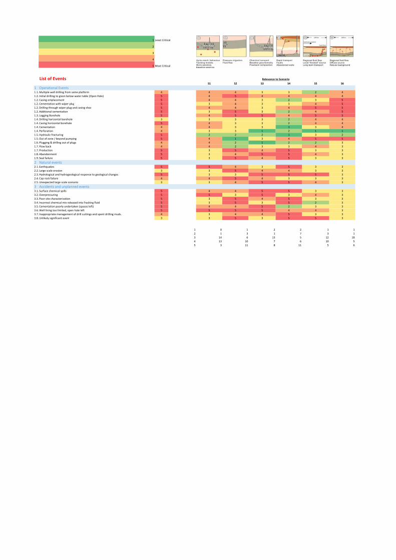
1 Least Critical
2
3
4
5 Most Critical
List of EventsS1 S2 S3 S4 S5 S6
1 Operational Events1.1.Multiple well drilling from same platform 4 4 4 3 3 2 4
1.2. Initial drilling to given below water table (Open Hole) 5 4 5 4 4 4 4
1.2. Casing emplacement 5 4 4 3 2 3 5
1.2. Cementation with wiper plug 5 3 4 3 3 4 5
1.2. Drilling through wiper plug and casing shoe 5 4 4 3 4 5 5
1.2. Additional cementation 5 3 5 3 2 4 5
1.3. Logging Borehole 5 4 5 5 4 5 5
1.4. Drilling horizontal borehole 3 3 3 3 2 4 4
1.4. Casing horizontal borehole 5 4 3 3 2 4 4
1.4. Cementation 4 4 3 3 1 3 4
1.4. Perforation 4 3 3 1 2 1 1
1.5. Hydraulic fracturing 5 2 2 2 1 3 2
1.5.Out of zone / beyond pumping 5 4 1 3 4 5 5
1.6. Plugging & drilling out of plugs 4 4 2 1 2 2 3
1.7. Flow back 4 4 2 3 3 4 3
1.7. Production 5 3 5 4 5 3 3
1.8. Abandonment 5 3 4 5 5 4 3
1.9. Seal failure 5 3 5 4 5 3 3
2 Natural events2.1. Earthquakes 5 5 4 3 5 3 3
2.2. Large scale erosion 3 3 5 4 4 3 3
2.3. Hydrological and hydrogeological response to geological changes 5 3 3 5 5 5 3
2.4. Cap rock failure 4 4 5 4 3 3 3
2.5.Unexpected large scale scenario 3 3 4 5 5 4 3
3 Accidents and unplanned events 3.1. Surface chemical spills 5 4 4 5 5 3 3
3.2.Overpressuring 5 5 3 5 3 4 3
3.3. Poor site characterization 5 3 5 4 5 3 3
3.4. Incorrect chemical mix released into fracking fluid 5 3 5 3 5 2 3
3.5. Cementation poorly undertaken (spaces left) 5 4 4 5 2 3 3
3.6.Well lining too limited, open hole left 5 5 5 5 4 4 3
3.7. Inappropriate management of drill cuttings and spent drilling muds. 4 3 4 4 5 3 3
3.8.Unlikely significant event 3 3 5 3 5 5 3
1 0 1 2 2 1 1
2 1 3 1 7 3 1
3 14 6 13 5 12 18
4 13 10 7 6 10 5
5 3 11 8 11 5 6
Relevance to Scenario

1 Least Critical
2
3
4
5 Most Critical
Importance
List of ProcessesS1 S2 S3 S4 S5 S6
1 Thermal effects on the borehole 1.1. Thermal effects on borehole and seal integrity. 5 4 2 1 2 5 5
1.2. Thermal effects on the injection point 5 4 5 5 2 3 3
2 Hydraulics / Fluid Pressure Dominated2.1. Fluid pressure exceeds rock fracking pressures generating new fractures 5 1 1 2 4 5 4
2.2. Fluid exceeds fault sealing pressures 4 3 4 4 1 3 3
2.3. Fluid pressure exceeds stability of part of the plant construction. 5 3 4 1 2 5 2
2.4. Displacement of surrounding formation fluids 5 1 4 4 2 5 3
2.5. Buoyancy‐driven flow 3 1 4 5 4 5 3
2.6. Advection and co‐migration of other gas 5 4 4 3 5 5 1
2.7. Formation of Gas hydrates 4 5 5 3 3 3 5
2.8. Water mediated transport 5 1 5 5 2 3 3
2.8.1. Advection 5 4 5 3 3 5 5
2.8.2. Dispersion 5 4 1 3 4 5 4
2.8.3. Diffusion 5 4 5 4 5 4 5
2.9. Hydraulic and production fluids and the associated contaminants release processes 5 1 4 4 5 4 5
3 Chemical3.1 Corrosive mixture attacks plant 5 4 5 1 3 3 1
3.2 Corrosive mixture attacks geology 3 4 2 5 3 5 2
3.3 Sorption and desorption 5 1 2 5 3 4 1
3.4 Mineral dissolution 5 5 1 1 5 5 2
3.5 Heavy metal release 4 1 4 4 4 4 4
4 Mechanical4.1 Soil and rock deformation around boreholes 5 5 1 1 1 3 4
4.1.1 Subsidence of ground related to gas extraction 5 5 4 3 3 3 5
4.2 Propagation of fractures beyond the target zone 5 4 5 3 5 3 5
4.3 Fluid exceeds fault sealing pressures 5 2 2 2 4 3 5
4.4 Fault valving 4 2 2 5 2 3 1
4.5 Generation of excavation disturbed zone around well 5 1 1 5 4 5 3
4.6 Micro‐cracking in the casing cements 5 2 5 1 5 4 5
1 8 5 6 2 0 4
2 3 5 2 6 0 3
3 2 0 6 6 10 6
4 9 8 5 6 5 4
5 4 8 7 6 11 9
Relevance to Scenario

1 Least Critical
2
3
4
5 Most Critical
List of FeaturesOverall Importance
In Risk Analysis
1 Hydrogeology S1 S2 S3 S4 S5 S6
1.1. Hydrocarbon bearing formation (Source)1.1.1. Type of the hydrocarbon bearing formation 3 3 1 1 2 1 1
1.1.2. Geometry of the hydrocarbon bearing formation 3 2 3 3 3 1 1
1.1.2.1 Thickness 4 4 4 4 2 2 2
1.1.3. Rock / Petrophysical properties of the hydrocarbon bearing formation 4 4 4 4 3 2 2
1.1.3.1 Lithology 3 3 2 2 3 3 3
1.1.3.2 Diagenesis 3 3 3 3 3 3 3
1.1.3.3 Pore architecture 1 1 1 1 1 1 1
1.1.3.4 Mineralogy 3 1 1 3 1 1 1
1.1.3.5 Kerogen type 3 1 1 3 1 1 1
1.1.3.6 Thermal maturation of source rock 1 1 1 1 1 1 1
1.1.3.7 Porosity 3 2 2 3 3 3 3
1.1.3.8 Intrinsic permeability 4 3 4 4 4 4 4
1.1.3.9 Relative permeability 4 3 4 4 4 3 3
1.1.3.10 Entry pressure 5 5 5 5 4 4 4
1.1.3.11 Residual saturation 1 1 1 1 1 1 1
1.1.3.12 Hysteresis 1 1 1 1 1 1 1
1.1.4. Stress and Mechanical properties 4 4 2 2 2 3 3
1.1.5. Heterogeneity of the hydrocarbon bearing formation 5 2 3 3 5 4 4
1.1.6. Fractures and faults within the hydrocarbon bearing formation 5 2 3 3 5 4 4
1.1.6.1 Porosity of the fracture 4 2 2 4 4 2 2
1.1.6.2 Intrinsic permeability of the fracture 4 2 4 4 4 4 4
1.1.6.3 Relative Permeability of the fractures 4 2 4 4 4 3 3
1.1.6.4 Fracture geometry 5 3 3 3 5 2 2
1.1.7. Undetected features within the hydrocarbon bearing formation 2 2 2 2 2 2 2
1.1.8. Vertical geothermal gradient of the hydrocarbon bearing formation 2 1 2 2 2 2 2
1.1.9. Formation pressure of the hydrocarbon bearing formation 3 2 3 3 3 2 2
1.2. Fluids1.2.1. Hydrocarbons 2 1 2 2 1 1 1
1.2.2. Natural formation water 2 1 2 2 1 1 1
1.2.3. Production fluids 2 1 2 2 1 1 1
1.2.4. Pore fluid composition within the fracking reservoir 2 1 2 2 1 1 1
1.2.5. Reservoir fluids 2 1 2 2 1 1 1
1.2.6. Other fluids 2 1 2 2 1 1 1
1.3. Overburden1.3.1. Geometry of the overburden 4 4 1 3 1 3 3
1.3.1.1 Thickness 4 4 1 3 1 3 3
1.3.2. Rock / Petrophysical properties of the overburden 2 2 1 2 1 1 1
1.3.2.1 Lithology 2 2 1 2 2 2 2
1.3.2.2 Diagenesis 3 3 1 2 2 3 3
1.3.2.3 Pore architecture 1 1 1 1 1 1 1
1.3.2.4 Mineralogy 1 1 1 1 1 1 1
1.3.2.5 Porosity 2 2 2 2 2 2 2
1.3.2.6 Intrinsic permeability 2 2 2 2 2 2 2
1.3.2.7 Relative permeability 2 2 2 2 2 2 2
1.3.2.8 Entry pressure 1 1 1 1 1 1 1
1.3.2.9 Residual saturation 1 1 1 1 1 1 1
1.3.2.10 Hysteresis 1 1 1 1 1 1 1
1.3.3. Free gas pocket within the overburden 3 3 3 3 1 2 2
1.3.4. Additional seals within the overburden 1 1 1 1 1 1 1
1.3.5. Unconformities within the overburden 2 2 2 1 1 2 2
1.3.6. Heterogeneity within the overburden 2 2 2 2 2 2 2
1.3.7. Fractures and faults within the overburden 5 5 5 5 1 5 5
1.3.7.1 Porosity of the fracture 3 3 3 3 3 3 3
1.3.7.2 Intrinsic permeability of the fracture 2 2 2 2 2 2 2
1.3.7.3 Relative Permeability of the fractures 2 2 2 2 2 2 2
1.3.7.4 Fracture geometry 5 1 5 4 5 1 1
1.3.8. Undetected features within the overburden 4 1 2 4 2 1 1
1.3.9. Vertical geothermal gradient of the overburden 1 1 1 1 1 1 1
1.3.10. Formation "overburden" pressure 1 1 1 1 1 1 1
1.3.11. Overburden pressure 1 1 1 1 1 1 1
1.4. Underburden1.4.1. Geometry of the underburden 1 1 1 1 1 1 1
1.4.1.1 Thickness 1 1 1 1 1 1 1
1.4.2. Rock / Petrophysical properties of the underburden 2 2 2 2 2 2 2
1.4.2.1 Lithology 2 2 2 2 2 2 2
1.4.2.2 Diagenesis 1 1 1 1 1 1 1
1.4.2.3 Pore architecture 1 1 1 1 1 1 1
1.4.2.4 Mineralogy 2 2 2 2 2 2 2
1.4.2.5 Porosity 1 1 1 1 1 1 1
1.4.2.6 Intrinsic permeability 1 1 1 1 1 1 1
1.4.2.7 Relative permeability 1 1 1 1 1 1 1
1.4.2.8 Entry pressure 1 1 1 1 1 1 1
1.4.2.9 Residual saturation 1 1 1 1 1 1 1
1.4.2.10 Hysteresis 1 1 1 1 1 1 1
1.4.3. Unconformities within the underburden 1 1 1 1 1 1 1
1.4.4. Heterogeneity within the underburden 1 1 1 1 1 1 1
1.4.5. Fractures and faults within the underburden 1 1 1 1 1 1 1
1.4.6. Undetected features within the underburden 1 1 1 1 1 1 1
1.4.7. Vertical geothermal gradient within the underburden 2 2 2 2 2 2 2
1.4.8. Formation "underburden" pressure 1 1 1 1 1 1 1
2 Near surface environment (Receptors)2.1. Terrestrial environment2.1.1. Geographical location 3 1 1 1 1 3 3
2.1.2. Soils and sediments 4 1 1 1 3 4 4
2.1.3. Near‐surface aquifers and surface water bodies 4 3 2 1 1 4 4
2.1.4. Terrestrial flora and fauna 1 1 1 1 1 1 1
2.1.5. Terrestrial ecological systems 1 1 1 1 1 1 1
2.1.6. Buildings 1 1 1 1 1 1 1
2.2. Marine environment 2.2.1. Local oceanography 1 1 1 1 1 1 1
2.2.2. Marine sediments 1 1 1 1 1 1 1
2.2.3. Marine Stratification and Mixing 1 1 1 1 1 1 1
2.2.4. Marine flora and fauna 1 1 1 1 1 1 1
2.2.5. Marine ecological systems 1 1 1 1 1 1 1
2.3. Human Environment2.3.1. Human characteristics 1 1 1 1 1 1 1
2.3.2. Diet and food processing 1 1 1 1 1 1 1
2.3.3. Lifestyles 1 1 1 1 1 1 1
2.3.4. Land and water use 1 1 1 1 1 1 1
2.3.5. Community characteristics 1 1 1 1 1 1 1
2.4. Atmosphere and meteorology
1 Hydro‐fracturing fluid1.1. Hydraulic injection fluid properties 4 2 2 4 1 3 3
1.2. Physical properties of injection fluid1.2.1. Injection fluid additives 4 2 2 4 1 3 3
1.2.2. Hydro‐fracturing fluids interactions 1 1 1 1 1 1 1
2 Site development 2.1. Logistics above ground 1 1 1 1 1 1 1
2.2. Baseline monitoring 3 1 1 1 1 3 3
3 Site operation 3.1. Drilling and completion3.1.1. Horizontal wells 5 5 5 5 5 1 1
3.1.2. Formation damage 4 4 4 4 4 2 2
Relevance to ScenarioA. Features of the Natural System
B. Unconventional Hydrocarbon Extraction

3.1.3. Well lining and completion 1 1 1 1 1 1 1
3.1.4. Workover 1 1 1 1 1 1 1
3.1.5. Monitoring wells 5 4 4 4 4 5 5
3.1.6. Well records 5 4 4 4 4 5 5
3.1.7. Well orientation 5 4 4 4 4 5 5
3.1.8. Well engineering 1 1 1 1 1 1 1
4 Site decommissioning 4.1. Closure and sealing of boreholes 4 4 4 4 4 2 2
4.2. Abandoned wells 4 4 4 4 4 2 2
1 60 57 52 65 60 60
2 24 27 23 18 23 23
3 10 8 13 8 14 14
4 11 12 17 12 7 7
5 3 4 3 5 4 4

1 Least Critical
2
3
4
5 Most Critical
List of EventsS1 S2 S3 S4 S5 S6
1 Operational Events1.1. Multiple well drilling from same platform 5 3 4 3 5 2 2
1.2. Initial drilling to given below water table (Open Hole) 4 3 4 4 4 2 2
1.2. Casing emplacement 4 3 3 3 4 2 2
1.2. Cementation with wiper plug 4 1 1 1 4 1 1
1.2. Drilling through wiper plug and casing shoe 3 3 3 3 3 2 2
1.2. Additional cementation 3 1 1 1 3 1 1
1.3. Logging Borehole 3 1 1 1 3 1 1
1.4. Drilling horizontal borehole 3 3 3 3 2 2 2
1.4. Casing horizontal borehole 4 3 3 3 4 2 2
1.4. Cementation 4 1 1 1 4 1 1
1.4. Perforation 3 3 3 3 3 2 2
1.5. Hydraulic fracturing 5 5 5 5 5 2 2
1.5. Out of zone / beyond pumping 4 1 1 1 4 4 4
1.6. Plugging & drilling out of plugs 1 1 1 1 1 1 1
1.7. Flow back 4 2 2 2 4 2 2
1.7. Production 5 2 2 2 5 2 2
1.8. Abandonment 5 2 2 2 5 2 2
1.9. Seal failure 5 2 2 2 5 2 2
2 Natural events2.1. Earthquakes 5 5 5 5 5 3 3
2.2. Large scale erosion 3 3 3 3 3 3 3
2.3. Hydrological and hydrogeological response to geological changes 2 2 2 2 2 2 2
2.4. Cap rock failure 5 4 5 5 5 3 3
2.5. Unexpected large scale scenario 3 3 3 3 3 3 3
3 Accidents and unplanned events 3.1. Surface chemical spills 3 1 1 1 1 3 3
3.2. Overpressuring 4 4 4 4 4 3 3
3.3. Poor site characterization 4 3 3 3 3 4 4
3.4. Incorrect chemical mix released into fracking fluid 5 2 2 5 2 2 2
3.5. Cementation poorly undertaken (spaces left) 3 2 3 3 3 1 1
3.6. Well lining too limited, open hole left 1 1 1 1 1 1 1
3.7. Inappropriate management of drill cuttings and spent drilling muds. 1 1 1 1 1 1 1
3.8. Unlikely significant event 1 1 1 1 1 1 1
1 10 10 10 5 9 9
2 7 6 5 3 14 14
3 10 9 10 8 6 6
4 2 3 2 8 2 2
5 2 3 4 7 0 0
Relevance to Scenario

1 Least Critical
2
3
4
5 Most Critical
Importance
List of ProcessesS1 S2 S3 S4 S5 S6
1 Thermal effects on the borehole 1.1. Thermal effects on borehole and seal integrity. 4 3 2 4 2 2 2
1.2. Thermal effects on the injection point 2 2 1 2 1 1 1
2 Hydraulics / Fluid Pressure Dominated2.1. Fluid pressure exceeds rock fracking pressures generating new fractures 5 3 4 3 5 2 2
2.2. Fluid exceeds fault sealing pressures 5 4 4 4 5 3 3
2.3. Fluid pressure exceeds stability of part of the plant construction. 1 1 1 1 1 1 1
2.4. Displacement of surrounding formation fluids 3 1 1 1 3 3 3
2.5. Buoyancy‐driven flow 3 1 1 1 3 3 3
2.6. Advection and co‐migration of other gas 4 3 3 4 3 2 2
2.7. Formation of Gas hydrates 3 1 1 3 3 2 2
2.8. Water mediated transport 4 2 2 2 4 3 3
2.8.1. Advection 4 3 2 3 4 4 4
2.8.2. Dispersion 4 2 4 3 4 4 4
2.8.3. Diffusion 5 2 2 5 1 1 1
2.9. Hydraulic and production fluids and the associated contaminants release processes 4 1 1 4 4 4 4
3 Chemical3.1 Corrosive mixture attacks plant 5 5 5 5 2 2 2
3.2 Corrosive mixture attacks geology 5 5 5 5 2 2 2
3.3 Sorption and desorption 5 5 5 5 2 2 2
3.4 Mineral dissolution 5 5 5 5 2 2 2
3.5 Heavy metal release 5 5 5 5 2 2 2
4 Mechanical4.1 Soil and rock deformation around boreholes 5 5 5 5 5 4 4
4.1.1 Subsidence of ground related to gas extraction 5 5 5 5 5 4 4
4.2 Propagation of fractures beyond the target zone 5 4 4 4 5 4 4
4.3 Fluid exceeds fault sealing pressures 5 4 4 4 5 3 3
4.4 Fault valving 5 4 4 4 5 2 2
4.5 Generation of excavation disturbed zone around well 4 4 4 4 3 2 2
4.6 Micro‐cracking in the casing cements 3 3 3 3 2 1 1
1 5 6 3 3 4 4
2 4 4 2 7 11 11
3 5 2 5 5 5 5
4 5 7 8 4 6 6
5 7 7 8 7 0 0
Relevance to Scenario

1 Least Critical
2
3
4
5 Most Critical
List of FeaturesOverall Importance
In Risk Analysis
1 Hydrogeology S1 S2 S3 S4 S5 S6
1.1. Hydrocarbon bearing formation (Source)1.1.1. Type of the hydrocarbon bearing formation 2 1 2 2 1 2 2
1.1.2. Geometry of the hydrocarbon bearing formation 3 3 2 1 1 3 2
1.1.2.1 Thickness 4 3 3 3 4 4 3
1.1.3. Rock / Petrophysical properties of the hydrocarbon bearing formation 5 5 3 1 5 5 5
1.1.3.1 Lithology 3 3 1 2 1 1 1
1.1.3.2 Diagenesis 2 2 1 2 1 1 1
1.1.3.3 Pore architecture 3 2 2 3 3 3 3
1.1.3.4 Mineralogy 4 3 1 4 3 3 3
1.1.3.5 Kerogen type 1 1 1 1 1 1 1
1.1.3.6 Thermal maturation of source rock 3 1 1 1 1 1 3
1.1.3.7 Porosity 4 1 2 4 2 2 2
1.1.3.8 Intrinsic permeability 4 3 3 4 4 4 4
1.1.3.9 Relative permeability 5 2 1 5 5 4 4
1.1.3.10 Entry pressure 5 1 5 5 5 2 3
1.1.3.11 Residual saturation 1 1 1 1 1 1 1
1.1.3.12 Hysteresis 1 1 1 1 1 1 1
1.1.4. Stress and Mechanical properties 4 4 1 1 2 2 2
1.1.5. Heterogeneity of the hydrocarbon bearing formation 4 3 2 4 3 4 4
1.1.6. Fractures and faults within the hydrocarbon bearing formation 5 4 4 5 5 5 5
1.1.6.1 Porosity of the fracture 5 4 4 5 4 4 4
1.1.6.2 Intrinsic permeability of the fracture 2 1 1 2 2 2 2
1.1.6.3 Relative Permeability of the fractures 4 1 3 1 4 3 3
1.1.6.4 Fracture geometry 2 1 1 2 2 2 2
1.1.7. Undetected features within the hydrocarbon bearing formation 4 3 3 3 3 3 4
1.1.8. Vertical geothermal gradient of the hydrocarbon bearing formation 1 1 1 1 1 1 1
1.1.9. Formation pressure of the hydrocarbon bearing formation 4 2 4 4 4 2 3
1.2. Fluids1.2.1. Hydrocarbons 5 2 2 5 1 5 5
1.2.2. Natural formation water 4 1 2 4 1 1 1
1.2.3. Production fluids 5 1 5 5 2 2 2
1.2.4. Pore fluid composition within the fracking reservoir 5 1 3 5 4 4 4
1.2.5. Reservoir fluids 5 2 2 5 1 3 3
1.2.6. Other fluids 3 1 1 3 2 2 2
1.3. Overburden1.3.1. Geometry of the overburden 3 3 3 1 1 1 1
1.3.1.1 Thickness 3 3 3 1 2 2 1
1.3.2. Rock / Petrophysical properties of the overburden 4 4 2 2 2 2 2
1.3.2.1 Lithology 1 1 1 1 1 1 1
1.3.2.2 Diagenesis 5 2 1 5 2 3 1
1.3.2.3 Pore architecture 4 1 1 2 2 4 2
1.3.2.4 Mineralogy 3 1 1 3 1 2 1
1.3.2.5 Porosity 3 3 3 2 3 3 3
1.3.2.6 Intrinsic permeability 1 1 1 1 1 1 1
1.3.2.7 Relative permeability 2 1 1 2 1 1 1
1.3.2.8 Entry pressure 3 1 2 3 3 2 1
1.3.2.9 Residual saturation 1 1 1 1 1 1 1
1.3.2.10 Hysteresis 3 1 1 1 3 3 2
1.3.3. Free gas pocket within the overburden 3 3 3 1 2 2 2
1.3.4. Additional seals within the overburden 3 1 1 1 1 3 2
1.3.5. Unconformities within the overburden 4 2 4 2 1 2 2
1.3.6. Heterogeneity within the overburden 4 3 4 1 4 2 3
1.3.7. Fractures and faults within the overburden 5 3 3 3 5 2 4
1.3.7.1 Porosity of the fracture 4 1 3 4 4 3 3
1.3.7.2 Intrinsic permeability of the fracture 3 1 1 3 2 1 1
1.3.7.3 Relative Permeability of the fractures 4 1 2 3 4 3 3
1.3.7.4 Fracture geometry 3 1 3 2 3 3 1
1.3.8. Undetected features within the overburden 5 1 2 5 3 3 4
1.3.9. Vertical geothermal gradient of the overburden 3 1 3 3 3 2 2
1.3.10. Formation "overburden" pressure 5 4 4 5 4 3 2
1.3.11. Overburden pressure 4 3 3 3 3 3 4
1.4. Underburden1.4.1. Geometry of the underburden 4 3 3 3 4 3 2
1.4.1.1 Thickness 1 1 1 1 1 1 1
1.4.2. Rock / Petrophysical properties of the underburden 3 3 2 2 3 2 2
1.4.2.1 Lithology 3 3 1 1 2 2 2
1.4.2.2 Diagenesis 5 1 1 5 3 3 2
1.4.2.3 Pore architecture 3 2 3 3 3 3 3
1.4.2.4 Mineralogy 3 1 2 3 3 2 3
1.4.2.5 Porosity 2 1 2 2 2 2 1
1.4.2.6 Intrinsic permeability 1 1 1 1 1 1 1
1.4.2.7 Relative permeability 1 1 1 1 1 1 1
1.4.2.8 Entry pressure 1 1 1 1 1 1 1
1.4.2.9 Residual saturation 5 1 2 5 4 2 1
1.4.2.10 Hysteresis 4 1 2 4 4 1 3
1.4.3. Unconformities within the underburden 3 1 3 2 3 1 1
1.4.4. Heterogeneity within the underburden 3 1 3 3 2 2 1
1.4.5. Fractures and faults within the underburden 4 3 3 4 3 3 3
1.4.6. Undetected features within the underburden 3 3 2 3 2 1 1
1.4.7. Vertical geothermal gradient within the underburden 4 1 1 4 3 2 3
1.4.8. Formation "underburden" pressure
2 Near surface environment (Receptors)2.1. Terrestrial environment2.1.1. Geographical location 5 5 3 3 3 3 3
2.1.2. Soils and sediments 5 5 4 5 3 3 3
2.1.3. Near‐surface aquifers and surface water bodies 5 3 4 5 3 2 2
2.1.4. Terrestrial flora and fauna
2.1.5. Terrestrial ecological systems 1 1 1 1 1 1 1
2.1.6. Buildings 5 3 3 5 2 1 1
2.2. Marine environment 2.2.1. Local oceanography 4 4 4 4 3 2 3
2.2.2. Marine sediments 4 4 3 3 2 2 3
2.2.3. Marine Stratification and Mixing 5 4 3 5 2 2 3
2.2.4. Marine flora and fauna
2.2.5. Marine ecological systems 5 1 1 5 1 1 1
2.3. Human Environment2.3.1. Human characteristics 1 1 1 1 1 1 1
2.3.2. Diet and food processing 1 1 1 1 1 1 1
2.3.3. Lifestyles 1 1 1 1 1 1 1
2.3.4. Land and water use 5 5 1 1 1 1 1
2.3.5. Community characteristics 3 3 1 1 1 1 1
2.4. Atmosphere and meteorology
1 Hydro‐fracturing fluid1.1. Hydraulic injection fluid properties
1.2. Physical properties of injection fluid1.2.1. Injection fluid additives 4 4 2 4 3 3 3
1.2.2. Hydro‐fracturing fluids interactions 5 4 3 5 4 3 3
2 Site development 2.1. Logistics above ground 4 1 1 1 1 1 1
2.2. Baseline monitoring 4 4 2 2 2 2 2
3 Site operation 3.1. Drilling and completion3.1.1. Horizontal wells 4 4 3 4 3 3 3
3.1.2. Formation damage 5 3 5 4 4 4 4
Relevance to ScenarioA. Features of the Natural System
B. Unconventional Hydrocarbon Extraction

3.1.3. Well lining and completion 4 3 2 4 3 3 3
3.1.4. Workover 1 1 1 1 1 1 1
3.1.5. Monitoring wells 5 5 1 1 1 1 1
3.1.6. Well records 4 4 1 4 3 3 2
3.1.7. Well orientation 5 5 5 5 5 3 4
3.1.8. Well engineering 5 5 3 4 4 3 4
4 Site decommissioning 4.1. Closure and sealing of boreholes
4.2. Abandoned wells
1 49 41 32 34 32 38
2 9 21 15 20 30 23
3 24 27 18 26 29 26
4 13 9 17 16 8 12
5 7 4 20 6 3 3
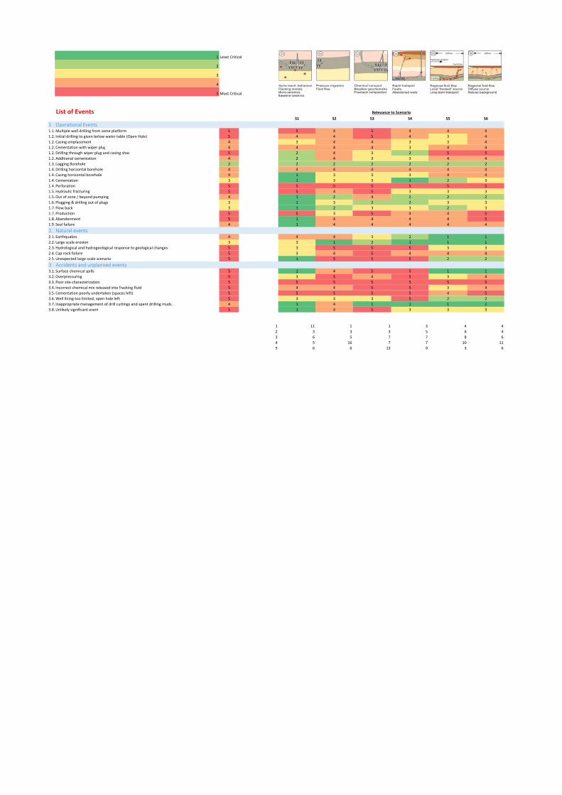
1 Least Critical
2
3
4
5 Most Critical
List of EventsS1 S2 S3 S4 S5 S6
1 Operational Events1.1.Multiple well drilling from same platform 5 5 4 5 4 4 4
1.2. Initial drilling to given below water table (Open Hole) 5 4 4 5 4 3 4
1.2. Casing emplacement 4 3 4 4 3 3 4
1.2. Cementation with wiper plug 4 4 4 4 3 4 4
1.2. Drilling through wiper plug and casing shoe 5 2 4 3 2 5 5
1.2. Additional cementation 4 2 4 3 3 4 4
1.3. Logging Borehole 2 2 2 2 2 2 2
1.4. Drilling horizontal borehole 4 4 4 4 4 4 4
1.4. Casing horizontal borehole 4 1 3 3 3 4 4
1.4. Cementation 3 1 3 3 1 2 3
1.4. Perforation 5 5 5 5 5 5 5
1.5. Hydraulic fracturing 5 5 4 5 3 3 3
1.5.Out of zone / beyond pumping 4 1 2 4 2 2 2
1.6. Plugging & drilling out of plugs 3 1 3 2 2 3 3
1.7. Flow back 3 1 2 3 3 2 3
1.7. Production 5 5 3 5 4 4 5
1.8. Abandonment 5 1 4 4 4 4 5
1.9. Seal failure 4 1 4 4 4 4 4
2 Natural events2.1. Earthquakes 4 4 4 3 2 1 1
2.2. Large scale erosion 3 3 1 2 1 1 1
2.3. Hydrological and hydrogeological response to geological changes 5 3 5 5 5 3 3
2.4. Cap rock failure 5 3 4 5 4 4 4
2.5.Unexpected large scale scenario 5 1 5 5 5 2 2
3 Accidents and unplanned events 3.1. Surface chemical spills 5 1 4 5 5 1 1
3.2.Overpressuring 5 3 5 4 5 3 4
3.3. Poor site characterization 5 5 5 5 5 5 5
3.4. Incorrect chemical mix released into fracking fluid 5 4 4 5 5 3 4
3.5. Cementation poorly undertaken (spaces left) 5 5 5 5 5 4 5
3.6.Well lining too limited, open hole left 5 3 3 3 5 2 2
3.7. Inappropriate management of drill cuttings and spent drilling muds. 4 1 4 1 1 1 1
3.8.Unlikely significant event 5 1 4 5 3 3 3
1 11 1 1 3 4 4
2 3 3 3 5 6 4
3 6 5 7 7 8 6
4 5 16 7 7 10 11
5 6 6 13 9 3 6
Relevance to Scenario

1 Least Critical
2
3
4
5 Most Critical
Importance
List of ProcessesS1 S2 S3 S4 S5 S6
1 Thermal effects on the borehole 1.1. Thermal effects on borehole and seal integrity. 5 3 3 5 3 3 3
1.2. Thermal effects on the injection point 3 3 3 2 1 2 2
2 Hydraulics / Fluid Pressure Dominated 5 3 2 3 5 4 4
2.1. Fluid pressure exceeds rock fracking pressures generating new fractures 5 3 3 4 5 4 4
2.2. Fluid exceeds fault sealing pressures 5 3 4 3 4 4 5
2.3. Fluid pressure exceeds stability of part of the plant construction. 5 5 5 2 4 4 5
2.4. Displacement of surrounding formation fluids 5 5 5 3 5 4 4
2.5. Buoyancy‐driven flow 5 3 5 5 4 4 4
2.6. Advection and co‐migration of other gas 3 3 3 3 3 2 2
2.7. Formation of Gas hydrates 2 2 2 1 2 1 2
2.8. Water mediated transport 4 4 2 4 3 3 3
2.8.1. Advection 4 4 2 4 3 4 4
2.8.2. Dispersion 5 4 5 3 5 4 4
2.8.3. Diffusion 5 5 5 5 5 4 4
2.9. Hydraulic and production fluids and the associated contaminants release processes 5 5 5 5 5 4 4
3 Chemical3.1 Corrosive mixture attacks plant 5 3 4 5 5 2 2
3.2 Corrosive mixture attacks geology 5 5 5 5 5 5 5
3.3 Sorption and desorption 5 5 5 5 5 4 4
3.4 Mineral dissolution 5 5 5 5 5 2 3
3.5 Heavy metal release 5 5 5 5 5 2 2
4 Mechanical4.1 Soil and rock deformation around boreholes 4 3 2 3 4 4 4
4.1.1 Sub 2 5 5 5 5 5 4 4
4.2 Propagation of fractures beyond the target zone 4 3 3 4 3 2 2
4.3 Fluid exceeds fault sealing pressures 4 3 3 4 3 2 3
4.4 Fault valving 5 5 5 5 5 4 4
4.5 Generation of excavation disturbed zone around well 5 3 5 5 5 3 4
4.6 Micro‐cracking in the casing cements 5 5 5 5 5 5 5
1 0 0 1 1 1 0
2 1 5 2 1 7 6
3 12 6 6 6 3 4
4 3 2 5 4 14 13
5 11 14 13 15 2 4
Relevance to Scenario

1 Least Critical
2
3
4
5 Most Critical
List of FeaturesOverall Importance
In Risk Analysis
1 Hydrogeology S1 S2 S3 S4 S5 S6
1.1. Hydrocarbon bearing formation (Source)1.1.1. Type of the hydrocarbon bearing formation 1 1 1 1 1 1 1
1.1.2. Geometry of the hydrocarbon bearing formation 2 2 2 1 1 1 1
1.1.2.1 Thickness 2 1 2 1 1 1 2
1.1.3. Rock / Petrophysical properties of the hydrocarbon bearing formation 4 4 4 4 4 4 4
1.1.3.1 Lithology 5 5 5 3 4 5 5
1.1.3.2 Diagenesis 4 1 2 4 4 4 3
1.1.3.3 Pore architecture 4 4 4 4 2 3 3
1.1.3.4 Mineralogy 5 2 2 5 2 2 2
1.1.3.5 Kerogen type 5 1 2 5 2 4 3
1.1.3.6 Thermal maturation of source rock 3 2 2 2 2 3 3
1.1.3.7 Porosity 5 3 5 5 2 4 5
1.1.3.8 Intrinsic permeability 5 3 5 3 5 5 4
1.1.3.9 Relative permeability 5 4 5 5 5 4 3
1.1.3.10 Entry pressure 5 5 5 5 5 4 5
1.1.3.11 Residual saturation 4 2 4 1 1 1 1
1.1.3.12 Hysteresis 2 2 2 1 1 1 1
1.1.4. Stress and Mechanical properties 5 5 4 1 4 4 1
1.1.5. Heterogeneity of the hydrocarbon bearing formation 5 5 4 4 3 4 4
1.1.6. Fractures and faults within the hydrocarbon bearing formation 5 4 3 3 5 4 2
1.1.6.1 Porosity of the fracture 5 5 4 4 5 2 2
1.1.6.2 Intrinsic permeability of the fracture 5 5 5 3 5 3 2
1.1.6.3 Relative Permeability of the fractures 5 5 5 3 3 4 2
1.1.6.4 Fracture geometry 5 5 4 4 4 2 2
1.1.7. Undetected features within the hydrocarbon bearing formation 2 1 2 1 2 2 2
1.1.8. Vertical geothermal gradient of the hydrocarbon bearing formation 3 1 1 3 1 1 1
1.1.9. Formation pressure of the hydrocarbon bearing formation 4 1 4 2 2 2 3
1.2. Fluids1.2.1. Hydrocarbons 4 2 1 4 1 2 2
1.2.2. Natural formation water 4 1 1 4 1 2 2
1.2.3. Production fluids 4 1 1 4 1 2 2
1.2.4. Pore fluid composition within the fracking reservoir 5 1 1 5 1 2 2
1.2.5. Reservoir fluids 5 2 2 5 1 2 2
1.2.6. Other fluids 4 1 1 4 1 2 2
1.3. Overburden1.3.1. Geometry of the overburden 5 4 5 1 1 2 3
1.3.1.1 Thickness 5 4 5 1 2 3 3
1.3.2. Rock / Petrophysical properties of the overburden 4 4 4 1 1 1 1
1.3.2.1 Lithology 4 4 4 4 2 3 1
1.3.2.2 Diagenesis 4 1 1 4 2 4 1
1.3.2.3 Pore architecture 4 3 3 4 2 3 3
1.3.2.4 Mineralogy 4 1 1 4 2 3 1
1.3.2.5 Porosity 4 3 3 4 3 4 4
1.3.2.6 Intrinsic permeability 4 3 4 3 3 2 2
1.3.2.7 Relative permeability 4 3 4 3 3 2 2
1.3.2.8 Entry pressure 5 4 5 1 3 2 3
1.3.2.9 Residual saturation 4 2 4 2 1 1 2
1.3.2.10 Hysteresis 2 2 1 1 2 2 2
1.3.3. Free gas pocket within the overburden 3 1 3 1 2 2 2
1.3.4. Additional seals within the overburden 3 1 2 1 2 2 3
1.3.5. Unconformities within the overburden 2 1 2 1 1 2 2
1.3.6. Heterogeneity within the overburden 3 2 3 1 1 1 2
1.3.7. Fractures and faults within the overburden 2 1 2 2 1 1 2
1.3.7.1 Porosity of the fracture 3 1 2 3 1 3 3
1.3.7.2 Intrinsic permeability of the fracture 4 1 4 3 3 2 2
1.3.7.3 Relative Permeability of the fractures 4 1 4 3 4 2 2
1.3.7.4 Fracture geometry 5 1 3 2 5 1 2
1.3.8. Undetected features within the overburden 5 1 1 1 2 5 1
1.3.9. Vertical geothermal gradient of the overburden 5 1 1 2 2 5 1
1.3.10. Formation "overburden" pressure 4 2 4 1 2 4 2
1.3.11. Overburden pressure 5 2 4 1 5 3 4
1.4. Underburden1.4.1. Geometry of the underburden 1 1 1 1 1 1 1
1.4.1.1 Thickness 2 1 1 1 1 1 2
1.4.2. Rock / Petrophysical properties of the underburden 2 1 2 2 2 1 1
1.4.2.1 Lithology 2 1 2 2 2 1 2
1.4.2.2 Diagenesis 2 1 2 2 2 1 1
1.4.2.3 Pore architecture 3 1 2 2 3 1 2
1.4.2.4 Mineralogy 2 1 2 2 2 1 1
1.4.2.5 Porosity 3 1 2 2 3 1 2
1.4.2.6 Intrinsic permeability 4 1 1 2 4 1 1
1.4.2.7 Relative permeability 4 1 1 1 4 2 1
1.4.2.8 Entry pressure 4 1 1 1 4 2 3
1.4.2.9 Residual saturation 2 1 2 1 2 2 1
1.4.2.10 Hysteresis 2 1 2 1 1 1 1
1.4.3. Unconformities within the underburden 2 1 2 1 1 1 1
1.4.4. Heterogeneity within the underburden 2 1 2 1 1 1 1
1.4.5. Fractures and faults within the underburden 3 1 1 1 3 2 2
1.4.6. Undetected features within the underburden 1 1 1 1 1 1 1
1.4.7. Vertical geothermal gradient within the underburden 3 1 2 1 3 1 1
1.4.8. Formation "underburden" pressure 3 1 3 1 2 2 3
2 Near surface environment (Receptors)2.1. Terrestrial environment2.1.1. Geographical location 2 1 1 2 2 2 1
2.1.2. Soils and sediments 2 1 1 1 1 1 2
2.1.3. Near‐surface aquifers and surface water bodies 3 1 1 3 2 3 2
2.1.4. Terrestrial flora and fauna 2 1 1 1 1 2 2
2.1.5. Terrestrial ecological systems 2 1 1 2 1 2 2
2.1.6. Buildings 1 1 1 1 1 1 1
2.2. Marine environment 2.2.1. Local oceanography 2 1 2 1 2 2 2
2.2.2. Marine sediments 3 2 2 3 2 2 2
2.2.3. Marine Stratification and Mixing 3 2 1 3 2 2 2
2.2.4. Marine flora and fauna 1 1 1 1 1 1 1
2.2.5. Marine ecological systems 1 1 1 1 1 1 1
2.3. Human Environment2.3.1. Human characteristics 2 1 1 1 1 2 1
2.3.2. Diet and food processing 1 1 1 1 1 1 1
2.3.3. Lifestyles 1 1 1 1 1 1 1
2.3.4. Land and water use 2 1 1 2 2 2 1
2.3.5. Community characteristics 1 1 1 1 1 1 1
2.4. Atmosphere and meteorology
1 Hydro‐fracturing fluid1.1. Hydraulic injection fluid properties 4 4 4 3 3 3 2
1.2. Physical properties of injection fluid 4 4 4 4 4 3 4
1.2.1. Injection fluid additives 5 1 1 5 4 2 1
1.2.2. Hydro‐fracturing fluids interactions 4 4 4 2 2 2 4
2 Site development 2.1. Logistics above ground 2 1 1 1 1 2 2
2.2. Baseline monitoring 3 2 2 3 3 3 3
3 Site operation 3.1. Drilling and completion 1 1 1 2 2 3
3.1.1. Horizontal wells 4 4 3 1 2 2 2
3.1.2. Formation damage 4 4 2 2 2 2 3
Relevance to ScenarioA. Features of the Natural System
B. Unconventional Hydrocarbon Extraction

3.1.3. Well lining and completion 3 1 1 1 1 1 3
3.1.4. Workover 1 1 1 1 1 1 1
3.1.5. Monitoring wells 3 1 1 1 1 3 3
3.1.6. Well records 3 1 1 1 2 1 3
3.1.7. Well orientation 3 3 3 2 1 1 2
3.1.8. Well engineering 4 2 1 2 1 2 4
4 Site decommissioning 4.1. Closure and sealing of boreholes 3 1 1 2 3 3 3
4.2. Abandoned wells 4 1 1 2 4 4 4
1 65 43 48 41 36 35
2 16 28 22 35 41 42
3 7 9 16 14 15 21
4 14 20 16 12 14 9
5 8 10 8 8 4 3

1 Least Critical
2
3
4
5 Most Critical
List of FeaturesOverall Importance
In Risk Analysis
1 Hydrogeology S1 S2 S3 S4 S5 S6
1.1. Hydrocarbon bearing formation (Source)1.1.1. Type of the hydrocarbon bearing formation 4 3 3 3 1 4 4
1.1.2. Geometry of the hydrocarbon bearing formation 3 2 2 2 1 3 3
1.1.2.1 Thickness 4 4 3 3 1 3 3
1.1.3. Rock / Petrophysical properties of the hydrocarbon bearing formation 4 4 2 2 2 4 4
1.1.3.1 Lithology 5 5 4 4 5 5 5
1.1.3.2 Diagenesis 2 1 2 2 2 2 2
1.1.3.3 Pore architecture 2 1 2 2 2 2 2
1.1.3.4 Mineralogy 3 1 2 2 2 3 3
1.1.3.5 Kerogen type 4 1 2 2 2 4 4
1.1.3.6 Thermal maturation of source rock 4 1 2 2 2 4 4
1.1.3.7 Porosity 3 3 2 2 2 3 3
1.1.3.8 Intrinsic permeability 5 5 5 5 5 4 3
1.1.3.9 Relative permeability 5 5 5 5 5 4 3
1.1.3.10 Entry pressure 3 3 3 3 3 3 3
1.1.3.11 Residual saturation 3 1 1 1 1 3 3
1.1.3.12 Hysteresis 3 1 1 1 1 3 3
1.1.4. Stress and Mechanical properties 5 5 1 1 1 3 2
1.1.5. Heterogeneity of the hydrocarbon bearing formation 3 3 2 3 3 3 2
1.1.6. Fractures and faults within the hydrocarbon bearing formation 5 5 2 3 5 4 1
1.1.6.1 Porosity of the fracture 3 3 2 3 3 2 1
1.1.6.2 Intrinsic permeability of the fracture 5 5 2 3 5 5 1
1.1.6.3 Relative Permeability of the fractures 5 5 2 3 5 5 1
1.1.6.4 Fracture geometry 4 4 2 3 4 3 1
1.1.7. Undetected features within the hydrocarbon bearing formation 4 3 2 3 2 2 4
1.1.8. Vertical geothermal gradient of the hydrocarbon bearing formation 2 1 2 2 2 2 2
1.1.9. Formation pressure of the hydrocarbon bearing formation 5 5 4 4 4 4 4
1.2. Fluids1.2.1. Hydrocarbons 4 4 3 4 4 4 4
1.2.2. Natural formation water 4 3 3 4 3 3 3
1.2.3. Production fluids 4 2 2 4 2 4 4
1.2.4. Pore fluid composition within the fracking reservoir 4 3 2 4 2 4 4
1.2.5. Reservoir fluids 4 3 3 4 2 4 4
1.2.6. Other fluids 4 1 1 4 1 2 2
1.3. Overburden1.3.1. Geometry of the overburden 4 3 1 1 1 1 4
1.3.1.1 Thickness 5 5 3 3 1 3 5
1.3.2. Rock / Petrophysical properties of the overburden 5 5 2 2 2 2 5
1.3.2.1 Lithology 5 5 4 4 4 4 5
1.3.2.2 Diagenesis 4 4 1 3 2 2 4
1.3.2.3 Pore architecture 4 2 1 3 2 2 4
1.3.2.4 Mineralogy 3 1 1 3 2 2 2
1.3.2.5 Porosity 4 3 3 3 2 3 4
1.3.2.6 Intrinsic permeability 5 5 5 4 4 3 5
1.3.2.7 Relative permeability 5 5 5 4 4 3 5
1.3.2.8 Entry pressure 2 2 2 2 2 2 2
1.3.2.9 Residual saturation 4 2 2 2 2 4 4
1.3.2.10 Hysteresis 2 1 1 1 1 2 2
1.3.3. Free gas pocket within the overburden 3 3 1 1 1 2 2
1.3.4. Additional seals within the overburden 4 4 3 3 1 2 4
1.3.5. Unconformities within the overburden 4 4 3 3 1 2 4
1.3.6. Heterogeneity within the overburden 2 2 2 2 2 2 2
1.3.7. Fractures and faults within the overburden 5 5 5 4 5 5 1
1.3.7.1 Porosity of the fracture 2 2 2 2 2 2 1
1.3.7.2 Intrinsic permeability of the fracture 5 5 5 4 5 5 1
1.3.7.3 Relative Permeability of the fractures 5 5 5 4 5 5 1
1.3.7.4 Fracture geometry 5 4 4 4 5 5 1
1.3.8. Undetected features within the overburden 4 2 2 2 2 2 4
1.3.9. Vertical geothermal gradient of the overburden 2 1 2 2 2 2 2
1.3.10. Formation "overburden" pressure 5 5 2 2 2 4 4
1.3.11. Overburden pressure 5 5 2 2 2 2 2
1.4. Underburden1.4.1. Geometry of the underburden 2 2 1 1 1 1 1
1.4.1.1 Thickness 2 2 1 1 1 1 1
1.4.2. Rock / Petrophysical properties of the underburden 3 3 2 2 1 2 2
1.4.2.1 Lithology 3 3 3 3 3 2 2
1.4.2.2 Diagenesis 3 3 1 2 1 2 2
1.4.2.3 Pore architecture 2 1 1 2 1 2 2
1.4.2.4 Mineralogy 3 1 1 3 1 2 2
1.4.2.5 Porosity 2 2 2 2 1 2 2
1.4.2.6 Intrinsic permeability 4 4 3 3 2 4 2
1.4.2.7 Relative permeability 4 4 3 3 2 4 2
1.4.2.8 Entry pressure 3 3 2 2 2 2 1
1.4.2.9 Residual saturation 4 1 2 4 4 2 2
1.4.2.10 Hysteresis 1 1 1 1 1 1 1
1.4.3. Unconformities within the underburden 2 2 2 2 1 1 1
1.4.4. Heterogeneity within the underburden 2 2 2 2 1 1 1
1.4.5. Fractures and faults within the underburden 3 3 2 2 2 2 1
1.4.6. Undetected features within the underburden 2 2 2 2 2 2 2
1.4.7. Vertical geothermal gradient within the underburden 1 1 1 1 1 1 1
1.4.8. Formation "underburden" pressure 4 4 2 2 2 3 3
2 Near surface environment (Receptors)2.1. Terrestrial environment2.1.1. Geographical location 4 3 1 1 4 4 4
2.1.2. Soils and sediments 4 1 1 1 4 4 4
2.1.3. Near‐surface aquifers and surface water bodies 5 1 1 1 5 5 5
2.1.4. Terrestrial flora and fauna 4 1 1 1 4 4 4
2.1.5. Terrestrial ecological systems 4 1 1 1 4 4 4
2.1.6. Buildings 5 3 1 1 5 5 5
2.2. Marine environment 2.2.1. Local oceanography 1 1 1 1 1 1 1
2.2.2. Marine sediments 1 1 1 1 1 1 1
2.2.3. Marine Stratification and Mixing 1 1 1 1 1 1 1
2.2.4. Marine flora and fauna 1 1 1 1 1 1 1
2.2.5. Marine ecological systems 1 1 1 1 1 1 1
2.3. Human Environment 0
2.3.1. Human characteristics 2 1 1 1 1 2 2
2.3.2. Diet and food processing 4 1 1 1 4 4 4
2.3.3. Lifestyles 2 1 1 1 2 2 2
2.3.4. Land and water use 4 3 1 1 4 4 4
2.3.5. Community characteristics 3 3 1 1 2 2 2
2.4. Atmosphere and meteorology
1 Hydro‐fracturing fluid1.1. Hydraulic injection fluid properties 5 4 4 5 5 3 3
1.2. Physical properties of injection fluid1.2.1. Injection fluid additives 5 5 4 5 5 4 4
1.2.2. Hydro‐fracturing fluids interactions 2 2 1 1 1 1 1
2 Site development 0
2.1. Logistics above ground 4 4 1 1 1 1 1
2.2. Baseline monitoring 5 5 5 5 5 5 5
3 Site operation 3.1. Drilling and completion3.1.1. Horizontal wells 5 5 5 5 5 4 4
3.1.2. Formation damage 3 3 3 3 3 3 3
Relevance to ScenarioA. Features of the Natural System
B. Unconventional Hydrocarbon Extraction

3.1.3. Well lining and completion 5 5 5 5 5 5 5
3.1.4. Workover 3 3 2 2 2 2 2
3.1.5. Monitoring wells 5 5 5 5 5 5 5
3.1.6. Well records 3 3 3 3 3 3 3
3.1.7. Well orientation 4 4 2 2 2 2 2
3.1.8. Well engineering 4 4 3 3 3 3 3
4 Site decommissioning 4.1. Closure and sealing of boreholes 5 1 3 3 5 5 5
4.2. Abandoned wells 5 1 3 3 5 5 5
1 31 35 28 32 14 25
2 15 38 30 35 35 28
3 24 18 26 8 20 15
4 15 6 16 13 25 27
5 23 11 8 20 14 13

1 Least Critical
2
3
4
5 Most Critical
List of EventsS1 S2 S3 S4 S5 S6
1 Operational Events1.1. Multiple well drilling from same platform 4 3 3 3 3 3 4
1.2. Initial drilling to given below water table (Open Hole) 1 1 1 1 1 1 1
1.2. Casing emplacement 4 3 4 3 2 2 2
1.2. Cementation with wiper plug 2 2 2 2 2 2 2
1.2. Drilling through wiper plug and casing shoe 2 2 2 2 2 2 2
1.2. Additional cementation 4 4 4 4 2 2 2
1.3. Logging Borehole 4 4 4 4 2 2 2
1.4. Drilling horizontal borehole 5 5 5 2 2 4 4
1.4. Casing horizontal borehole 5 5 5 2 2 4 2
1.4. Cementation 5 5 5 2 2 4 2
1.4. Perforation 5 5 5 2 2 1 1
1.5. Hydraulic fracturing 5 5 5 2 5 3 3
1.5. Out of zone / beyond pumping 5 5 5 2 5 5 5
1.6. Plugging & drilling out of plugs 2 2 2 2 2 1 1
1.7. Flow back 5 5 2 5 3 2 2
1.7. Production 5 5 5 5 3 3 3
1.8. Abandonment 3 3 3 3 3 3 3
1.9. Seal failure 3 3 3 3 3 1 1
2 Natural events2.1. Earthquakes 5 1 1 1 1 5 3
2.2. Large scale erosion 3 1 1 1 1 3 3
2.3. Hydrological and hydrogeological response to geological changes 3 1 1 1 1 3 3
2.4. Cap rock failure 3 1 1 1 1 3 2
2.5. Unexpected large scale scenario 1 1 1 1 1 1 1
3 Accidents and unplanned events 3.1. Surface chemical spills 5 5 1 5 1 1 1
3.2. Overpressuring 4 4 2 2 1 1 1
3.3. Poor site characterization 5 3 3 3 5 3 3
3.4. Incorrect chemical mix released into fracking fluid 5 3 3 5 4 3 3
3.5. Cementation poorly undertaken (spaces left) 5 5 5 5 4 2 2
3.6. Well lining too limited, open hole left 3 3 3 2 2 2 2
3.7. Inappropriate management of drill cuttings and spent drilling muds. 1 1 1 1 1 1 1
3.8. Unlikely significant event 1 1 1 1 1 1 1
1 8 9 8 10 9 9
2 3 5 11 11 8 11
3 7 6 5 5 9 8
4 3 3 2 2 3 2
5 10 8 5 3 2 1
Relevance to Scenario

1 Least Critical
2
3
4
5 Most Critical
Importance
List of ProcessesS1 S2 S3 S4 S5 S6
1 Thermal effects on the borehole 1.1. Thermal effects on borehole and seal integrity. 5 5 5 5 2 5 5
1.2. Thermal effects on the injection point 2 2 2 2 1 1 1
2 Hydraulics / Fluid Pressure Dominated2.1. Fluid pressure exceeds rock fracking pressures generating new fractures 5 5 5 1 5 1 1
2.2. Fluid exceeds fault sealing pressures 5 1 1 1 5 2 1
2.3. Fluid pressure exceeds stability of part of the plant construction. 5 5 5 3 2 2 1
2.4. Displacement of surrounding formation fluids 5 1 5 3 5 4 4
2.5. Buoyancy‐driven flow 5 1 1 1 2 4 5
2.6. Advection and co‐migration of other gas 5 1 5 4 5 5 5
2.7. Formation of Gas hydrates 2 2 1 1 1 2 2
2.8. Water mediated transport 5 1 5 4 5 5 5
2.8.1. Advection 5 4 5 4 5 5 5
2.8.2. Dispersion 3 2 3 3 3 3 3
2.8.3. Diffusion 5 2 1 5 1 4 4
2.9. Hydraulic and production fluids and the associated contaminants release processes 5 5 5 5 5 4 4
3 Chemical3.1 Corrosive mixture attacks plant 5 3 3 5 2 2 2
3.2 Corrosive mixture attacks geology 5 3 3 5 2 2 2
3.3 Sorption and desorption 5 2 3 5 3 4 4
3.4 Mineral dissolution 5 2 3 5 3 4 4
3.5 Heavy metal release 5 2 2 5 2 4 4
4 Mechanical4.1 Soil and rock deformation around boreholes 5 5 5 3 5 1 1
4.1.1 Subsidence of ground related to gas extraction 4 1 1 3 1 4 4
4.2 Propagation of fractures beyond the target zone 5 5 5 3 5 1 1
4.3 Fluid exceeds fault sealing pressures 5 1 1 1 5 2 1
4.4 Fault valving 3 1 1 1 3 2 1
4.5 Generation of excavation disturbed zone around well 2 1 1 1 2 2 2
4.6 Micro‐cracking in the casing cements 5 5 5 5 2 5 5
1 9 8 7 4 4 8
2 7 2 1 8 8 4
3 2 5 6 4 1 1
4 1 0 3 0 8 7
5 7 11 9 10 5 6
Relevance to Scenario

1 Least Critical
2
3
4
5 Most Critical
List of FeaturesOverall Importance
In Risk Analysis
1 Hydrogeology S1 S2 S3 S4 S5 S6
1.1. Hydrocarbon bearing formation (Source)1.1.1. Type of the hydrocarbon bearing formation 4 4 3 1 1 1 1
1.1.2. Geometry of the hydrocarbon bearing formation 4 4 1 1 1 1 1
1.1.2.1 Thickness 5 5 1 1 1 1 1
1.1.3. Rock / Petrophysical properties of the hydrocarbon bearing formation 5 5 5 5 4 5 4
1.1.3.1 Lithology 5 5 4 5 5 5 5
1.1.3.2 Diagenesis 4 1 3 1 4 4 3
1.1.3.3 Pore architecture 5 1 5 4 2 3 3
1.1.3.4 Mineralogy 5 1 4 5 2 4 4
1.1.3.5 Kerogen type 4 1 2 4 2 4 3
1.1.3.6 Thermal maturation of source rock 3 1 2 2 2 2 3
1.1.3.7 Porosity 5 5 5 4 2 3 3
1.1.3.8 Intrinsic permeability 5 5 5 3 5 4 3
1.1.3.9 Relative permeability 5 4 4 3 5 4 3
1.1.3.10 Entry pressure 5 1 1 3 5 4 3
1.1.3.11 Residual saturation 4 3 3 4 1 1 1
1.1.3.12 Hysteresis 1 1 1 1 1 1 1
1.1.4. Stress and Mechanical properties 5 5 4 1 1 2 1
1.1.5. Heterogeneity of the hydrocarbon bearing formation 5 5 4 3 3 3 3
1.1.6. Fractures and faults within the hydrocarbon bearing formation 5 5 5 4 5 3 3
1.1.6.1 Porosity of the fracture 5 5 5 4 5 2 3
1.1.6.2 Intrinsic permeability of the fracture 5 5 5 4 5 3 3
1.1.6.3 Relative Permeability of the fractures 4 4 4 4 4 3 3
1.1.6.4 Fracture geometry 5 5 5 4 4 3 3
1.1.7. Undetected features within the hydrocarbon bearing formation 3 1 3 2 2 2 3
1.1.8. Vertical geothermal gradient of the hydrocarbon bearing formation 4 1 3 4 2 2 3
1.1.9. Formation pressure of the hydrocarbon bearing formation 4 1 3 4 2 2 3
1.2. Fluids1.2.1. Hydrocarbons 5 2 2 5 1 2 2
1.2.2. Natural formation water 5 2 2 5 1 2 2
1.2.3. Production fluids 5 2 2 5 1 2 2
1.2.4. Pore fluid composition within the fracking reservoir 5 2 2 5 1 2 2
1.2.5. Reservoir fluids 5 2 2 5 1 2 2
1.2.6. Other fluids 5 2 2 5 1 2 2
1.3. Overburden1.3.1. Geometry of the overburden 3 3 1 1 1 1 2
1.3.1.1 Thickness 3 3 1 1 1 1 2
1.3.2. Rock / Petrophysical properties of the overburden 5 5 1 5 1 1 2
1.3.2.1 Lithology 5 4 1 5 2 3 2
1.3.2.2 Diagenesis 4 1 1 3 4 3 2
1.3.2.3 Pore architecture 3 1 1 1 2 3 2
1.3.2.4 Mineralogy 5 1 1 5 2 3 2
1.3.2.5 Porosity 5 5 1 1 5 4 2
1.3.2.6 Intrinsic permeability 5 5 1 1 1 2 2
1.3.2.7 Relative permeability 4 4 1 1 1 2 2
1.3.2.8 Entry pressure 2 1 1 1 1 2 2
1.3.2.9 Residual saturation 3 3 1 1 1 2 2
1.3.2.10 Hysteresis 2 1 1 1 1 2 2
1.3.3. Free gas pocket within the overburden 3 1 1 3 1 2 2
1.3.4. Additional seals within the overburden 2 1 1 1 1 2 2
1.3.5. Unconformities within the overburden 3 1 3 1 1 2 2
1.3.6. Heterogeneity within the overburden 4 3 4 2 1 2 2
1.3.7. Fractures and faults within the overburden 5 5 4 4 1 2 2
1.3.7.1 Porosity of the fracture 5 5 3 4 2 2 2
1.3.7.2 Intrinsic permeability of the fracture 5 5 3 4 4 2 2
1.3.7.3 Relative Permeability of the fractures 4 4 3 4 4 2 2
1.3.7.4 Fracture geometry 5 5 5 4 5 2 2
1.3.8. Undetected features within the overburden 5 1 3 2 2 5 2
1.3.9. Vertical geothermal gradient of the overburden 5 1 3 4 2 5 2
1.3.10. Formation "overburden" pressure 4 1 4 4 2 4 2
1.3.11. Overburden pressure 5 1 3 4 5 3 2
1.4. Underburden1.4.1. Geometry of the underburden 1 1 1 1 1 1 1
1.4.1.1 Thickness 1 1 1 1 1 1 1
1.4.2. Rock / Petrophysical properties of the underburden 5 5 2 1 4 2 1
1.4.2.1 Lithology 4 4 2 1 4 2 1
1.4.2.2 Diagenesis 2 1 2 1 2 2 1
1.4.2.3 Pore architecture 3 1 2 1 3 2 1
1.4.2.4 Mineralogy 4 1 2 1 4 2 1
1.4.2.5 Porosity 5 5 2 1 4 2 1
1.4.2.6 Intrinsic permeability 5 5 1 1 1 2 1
1.4.2.7 Relative permeability 4 4 1 1 1 2 1
1.4.2.8 Entry pressure 2 1 1 1 1 2 1
1.4.2.9 Residual saturation 3 3 2 1 3 2 1
1.4.2.10 Hysteresis 3 1 2 1 3 2 1
1.4.3. Unconformities within the underburden 3 1 2 1 3 2 1
1.4.4. Heterogeneity within the underburden 3 3 2 1 2 2 1
1.4.5. Fractures and faults within the underburden 5 5 2 1 2 2 1
1.4.6. Undetected features within the underburden 5 5 2 1 3 2 1
1.4.7. Vertical geothermal gradient within the underburden 4 1 2 1 4 2 1
1.4.8. Formation "underburden" pressure 1
2 Near surface environment (Receptors)2.1. Terrestrial environment2.1.1. Geographical location 1 1 1 1 1 1 1
2.1.2. Soils and sediments 1 1 1 1 1 1 1
2.1.3. Near‐surface aquifers and surface water bodies 2 1 1 2 1 1 1
2.1.4. Terrestrial flora and fauna 1 1 1 1 1 1 1
2.1.5. Terrestrial ecological systems 1 1 1 1 1 1 1
2.1.6. Buildings 1 1 1 1 1 1 1
2.2. Marine environment 2.2.1. Local oceanography 1 1 1 1 1 1 1
2.2.2. Marine sediments 1 1 1 1 1 1 1
2.2.3. Marine Stratification and Mixing 1 1 1 1 1 1 1
2.2.4. Marine flora and fauna 1 1 1 1 1 1 1
2.2.5. Marine ecological systems 1 1 1 1 1 1 1
2.3. Human Environment2.3.1. Human characteristics 1 1 1 1 1 1 1
2.3.2. Diet and food processing 1 1 1 1 1 1 1
2.3.3. Lifestyles 1 1 1 1 1 1 1
2.3.4. Land and water use 3 1 1 3 1 1 1
2.3.5. Community characteristics 1 1 1 1 1 1 1
2.4. Atmosphere and meteorology
1 Hydro‐fracturing fluid1.1. Hydraulic injection fluid properties
1.2. Physical properties of injection fluid1.2.1. Injection fluid additives 5 1 1 5 1 1 1
1.2.2. Hydro‐fracturing fluids interactions 5 1 1 5 1 1 1
2 Site development 2.1. Logistics above ground 1 1 1 1 1 1 1
2.2. Baseline monitoring 5 1 1 5 1 1 1
3 Site operation 3.1. Drilling and completion3.1.1. Horizontal wells 1 1 1 1 1 1 1
3.1.2. Formation damage 1 1 1 1 1 1 1
3.1.3. Well lining and completion 1 1 1 1 1 1 1
3.1.4. Workover 1 1 1 1 1 1 1
3.1.5. Monitoring wells 1 1 1 1 1 1 1
3.1.6. Well records 4 1 1 4 1 1 1
3.1.7. Well orientation 1 1 1 1 1 1 1
3.1.8. Well engineering 1 1 1 1 1 1 1
4 Site decommissioning 4.1. Closure and sealing of boreholes 1 1 1 4 3 1 1
4.2. Abandoned wells 1 1 1 4 4 1 1
1 61 54 58 58 40 54
2 6 21 5 18 42 32
3 7 13 7 7 12 17
4 9 9 22 13 8 2
5 23 9 15 10 4 1
Relevance to ScenarioA. Features of the Natural System
B. Unconventional Hydrocarbon Extraction

1 Least Critical
2
3
4
5 Most Critical
List of EventsS1 S2 S3 S4 S5 S6
1 Operational Events1.1. Multiple well drilling from same platform 4 3 3 1 3 2 4
1.2. Initial drilling to given below water table (Open Hole) 4 3 3 1 3 4 4
1.2. Casing emplacement 5 3 3 1 3 4 5
1.2. Cementation with wiper plug 5 3 3 1 3 4 5
1.2. Drilling through wiper plug and casing shoe 5 3 3 1 3 5 5
1.2. Additional cementation 5 3 3 1 3 4 5
1.3. Logging Borehole 5 3 3 1 3 5 5
1.4. Drilling horizontal borehole 4 3 3 1 3 4 4
1.4. Casing horizontal borehole 4 3 3 1 3 4 4
1.4. Cementation 4 3 3 1 3 4 4
1.4. Perforation 3 3 3 1 3 1 1
1.5. Hydraulic fracturing 5 5 5 5 5 3 2
1.5. Out of zone / beyond pumping 5 5 5 5 5 5 5
1.6. Plugging & drilling out of plugs 5 5 5 5 5 4 3
1.7. Flow back 5 5 5 5 5 4 3
1.7. Production 5 5 5 5 5 3 3
1.8. Abandonment 5 5 5 1 5 3 3
1.9. Seal failure 5 5 5 4 5 3 3
2 Natural events2.1. Earthquakes 5 5 5 1 5 3 3
2.2. Large scale erosion 5 5 5 1 5 3 3
2.3. Hydrological and hydrogeological response to geological changes 5 5 5 5 5 3 3
2.4. Cap rock failure 5 5 5 3 5 3 3
2.5. Unexpected large scale scenario 5 5 5 1 5 3 3
3 Accidents and unplanned events 3.1. Surface chemical spills 5 1 1 1 5 3 3
3.2. Overpressuring 5 5 5 5 5 3 3
3.3. Poor site characterization 5 5 5 5 5 3 3
3.4. Incorrect chemical mix released into fracking fluid 5 3 3 5 5 3 3
3.5. Cementation poorly undertaken (spaces left) 5 3 3 5 5 3 3
3.6. Well lining too limited, open hole left 5 3 3 5 5 3 3
3.7. Inappropriate management of drill cuttings and spent drilling muds. 5 3 3 1 5 3 3
3.8. Unlikely significant event 5 3 3 2 5 3 3
1 1 1 17 0 1 1
2 0 0 1 0 1 1
3 16 16 1 11 17 18
4 0 0 1 0 9 5
5 14 14 11 20 3 6
Relevance to Scenario

1 Least Critical
2
3
4
5 Most Critical
Importance
List of ProcessesS1 S2 S3 S4 S5 S6
1 Thermal effects on the borehole 1.1. Thermal effects on borehole and seal integrity. 5 4 4 1 3 5 5
1.2. Thermal effects on the injection point 4 4 4 1 1 4 4
2 Hydraulics / Fluid Pressure Dominated2.1. Fluid pressure exceeds rock fracking pressures generating new fractures 5 5 5 1 5 4 4
2.2. Fluid exceeds fault sealing pressures 5 5 5 1 3 3 3
2.3. Fluid pressure exceeds stability of part of the plant construction. 5 5 5 1 4 5 5
2.4. Displacement of surrounding formation fluids 5 5 5 5 5 4 4
2.5. Buoyancy‐driven flow 5 5 5 5 4 5 5
2.6. Advection and co‐migration of other gas 5 2 2 5 3 5 5
2.7. Formation of Gas hydrates 4 3 3 4 3 4 4
2.8. Water mediated transport 5 3 3 5 3 5 5
2.8.1. Advection 5 4 4 5 3 5 5
2.8.2. Dispersion 5 4 4 5 5 5 5
2.8.3. Diffusion 5 4 4 5 5 5 5
2.9. Hydraulic and production fluids and the associated contaminants release processes 5 5 5 5 5 5 5
3 Chemical3.1 Corrosive mixture attacks plant 5 5 5 1 5 4 4
3.2 Corrosive mixture attacks geology 5 5 5 5 5 4 4
3.3 Sorption and desorption 5 5 5 5 5 4 4
3.4 Mineral dissolution 5 5 5 5 5 4 4
3.5 Heavy metal release 5 5 5 5 5 4 4
4 Mechanical4.1 Soil and rock deformation around boreholes 5 5 5 1 5 4 4
4.1.1 Subsidence of ground related to gas extraction 5 5 5 1 5 4 4
4.2 Propagation of fractures beyond the target zone 5 5 5 5 5 4 4
4.3 Fluid exceeds fault sealing pressures 5 5 5 1 5 4 4
4.4 Fault valving 5 5 5 5 5 4 4
4.5 Generation of excavation disturbed zone around well 5 5 5 1 5 4 4
4.6 Micro‐cracking in the casing cements 5 5 5 3 5 4 4
1 0 0 10 1 0 0
2 1 1 0 0 0 0
3 2 2 1 6 1 1
4 5 5 1 2 16 16
5 18 18 14 17 9 9
Relevance to Scenario

1 Least Critical
2
3
4
5 Most Critical
List of FeaturesOverall Importance
In Risk Analysis
1 Hydrogeology S1 S2 S3 S4 S5 S6
1.1. Hydrocarbon bearing formation (Source)1.1.1. Type of the hydrocarbon bearing formation 5 4 2 5 1 2 3
1.1.2. Geometry of the hydrocarbon bearing formation 4 1 2 1 2 4 4
1.1.2.1 Thickness 3 3 2 1 2 1 1
1.1.3. Rock / Petrophysical properties of the hydrocarbon bearing formation 5 5 4 2 4 5 5
1.1.3.1 Lithology 5 5 4 5 5 4 4
1.1.3.2 Diagenesis 4 1 1 4 1 4 4
1.1.3.3 Pore architecture 5 5 4 2 4 4 3
1.1.3.4 Mineralogy 5 1 1 5 1 1 1
1.1.3.5 Kerogen type 5 1 1 5 1 1 1
1.1.3.6 Thermal maturation of source rock 4 3 2 4 2 2 2
1.1.3.7 Porosity 5 5 4 2 4 4 3
1.1.3.8 Intrinsic permeability 5 5 4 2 4 4 3
1.1.3.9 Relative permeability 5 5 4 2 4 4 3
1.1.3.10 Entry pressure 5 5 5 2 5 4 4
1.1.3.11 Residual saturation 3 1 3 1 2 1 2
1.1.3.12 Hysteresis 1 1 1 1 1 1 1
1.1.4. Stress and Mechanical properties 5 5 3 2 3 2 1
1.1.5. Heterogeneity of the hydrocarbon bearing formation 3 3 3 3 3 3 3
1.1.6. Fractures and faults within the hydrocarbon bearing formation 5 5 5 2 5 5 3
1.1.6.1 Porosity of the fracture 5 5 5 2 5 5 3
1.1.6.2 Intrinsic permeability of the fracture 5 5 5 2 5 5 3
1.1.6.3 Relative Permeability of the fractures 5 5 5 2 5 5 3
1.1.6.4 Fracture geometry 2 2 2 1 2 2 2
1.1.7. Undetected features within the hydrocarbon bearing formation 5 4 3 5 5 5 3
1.1.8. Vertical geothermal gradient of the hydrocarbon bearing formation 3 1 1 1 1 1 3
1.1.9. Formation pressure of the hydrocarbon bearing formation 3 3 1 2 2 2 2
1.2. Fluids1.2.1. Hydrocarbons 4 4 4 4 4 4 4
1.2.2. Natural formation water 4 2 4 2 3 3 3
1.2.3. Production fluids 4 4 4 4 4 2 2
1.2.4. Pore fluid composition within the fracking reservoir 4 4 4 4 4 2 2
1.2.5. Reservoir fluids 4 4 4 4 4 2 2
1.2.6. Other fluids 4 4 4 4 4 2 2
1.3. Overburden1.3.1. Geometry of the overburden 3 2 3 2 1 2 3
1.3.1.1 Thickness 2 2 1 1 1 1 2
1.3.2. Rock / Petrophysical properties of the overburden 5 2 2 1 2 5 2
1.3.2.1 Lithology 5 3 4 5 3 4 4
1.3.2.2 Diagenesis 4 1 1 4 1 4 4
1.3.2.3 Pore architecture 5 5 4 2 4 4 3
1.3.2.4 Mineralogy 5 1 1 5 1 1 1
1.3.2.5 Porosity 5 1 1 5 1 1 1
1.3.2.6 Intrinsic permeability 4 3 2 4 2 2 2
1.3.2.7 Relative permeability 5 5 4 2 4 4 3
1.3.2.8 Entry pressure 5 5 4 2 4 4 3
1.3.2.9 Residual saturation 5 5 4 2 4 4 3
1.3.2.10 Hysteresis 5 5 5 2 5 4 4
1.3.3. Free gas pocket within the overburden 4 4 2 3 1 3 2
1.3.4. Additional seals within the overburden 4 2 3 2 2 4 3
1.3.5. Unconformities within the overburden 4 2 3 2 2 4 3
1.3.6. Heterogeneity within the overburden 3 1 1 1 1 3 2
1.3.7. Fractures and faults within the overburden 4 4 3 2 4 4 4
1.3.7.1 Porosity of the fracture 4 4 3 2 4 4 4
1.3.7.2 Intrinsic permeability of the fracture 4 4 3 2 4 4 4
1.3.7.3 Relative Permeability of the fractures 4 4 3 2 4 4 4
1.3.7.4 Fracture geometry 2 2 2 1 2 2 2
1.3.8. Undetected features within the overburden 5 4 3 5 5 5 3
1.3.9. Vertical geothermal gradient of the overburden 3 1 1 1 1 1 3
1.3.10. Formation "overburden" pressure 3 3 1 2 2 2 2
1.3.11. Overburden pressure 3 3 1 2 2 2 2
1.4. Underburden1.4.1. Geometry of the underburden 1 1 1 1 1 1 1
1.4.1.1 Thickness 1 1 1 1 1 1 1
1.4.2. Rock / Petrophysical properties of the underburden 3 2 1 3 1 1 1
1.4.2.1 Lithology 1 1 1 1 1 1 1
1.4.2.2 Diagenesis 1 1 1 1 1 1 1
1.4.2.3 Pore architecture 3 2 1 3 1 1 1
1.4.2.4 Mineralogy 3 2 1 3 1 1 1
1.4.2.5 Porosity 3 2 1 3 1 1 1
1.4.2.6 Intrinsic permeability 3 2 1 3 1 1 1
1.4.2.7 Relative permeability 3 2 1 3 1 1 1
1.4.2.8 Entry pressure 3 2 1 3 1 1 1
1.4.2.9 Residual saturation 1 1 1 1 1 1 1
1.4.2.10 Hysteresis 1 1 1 1 1 1 1
1.4.3. Unconformities within the underburden 1 1 1 1 1 1 1
1.4.4. Heterogeneity within the underburden 1 1 1 1 1 1 1
1.4.5. Fractures and faults within the underburden 3 3 2 1 3 3 1
1.4.6. Undetected features within the underburden 4 3 2 4 3 3 1
1.4.7. Vertical geothermal gradient within the underburden 1 1 1 1 1 1 1
1.4.8. Formation "underburden" pressure 3 3 2 1 3 2 2
2 Near surface environment (Receptors)2.1. Terrestrial environment2.1.1. Geographical location 2 2 2 4 4 3
2.1.2. Soils and sediments 1 1 3 1 3 4
2.1.3. Near‐surface aquifers and surface water bodies 1 3 2 3 4 4
2.1.4. Terrestrial flora and fauna 2 1 1 3 3 3
2.1.5. Terrestrial ecological systems 2 1 1 3 3 3
2.1.6. Buildings 2 1 1 3 3 3
2.2. Marine environment 2.2.1. Local oceanography 1 1 3 1 2 2
2.2.2. Marine sediments 1 1 2 1 1 1
2.2.3. Marine Stratification and Mixing 1 1 2 1 1 1
2.2.4. Marine flora and fauna 2 1 1 3 3 3
2.2.5. Marine ecological systems 2 1 1 3 3 3
2.3. Human Environment2.3.1. Human characteristics 1 1 1 1 1 1
2.3.2. Diet and food processing 1 1 1 1 1 1
2.3.3. Lifestyles 1 1 1 1 1 1
2.3.4. Land and water use 1 1 1 2 2 2
2.3.5. Community characteristics 1 1 1 1 1 1
2.4. Atmosphere and meteorology 1 1 1 2 2 2
1 Hydro‐fracturing fluid1.1. Hydraulic injection fluid properties 3 3 5 2 3 2
1.2. Physical properties of injection fluid1.2.1. Injection fluid additives 3 3 5 2 3 2
1.2.2. Hydro‐fracturing fluids interactions 3 3 5 2 3 2
2 Site development 2.1. Logistics above ground 1 1 1 3 3 1
2.2. Baseline monitoring 4 2 2 3 2 1
3 Site operation 3.1. Drilling and completion3.1.1. Horizontal wells 1 1 1 4 3 2
3.1.2. Formation damage 2 3 1 5 5 1
Relevance to ScenarioA. Features of the Natural System
B. Unconventional Hydrocarbon Extraction

3.1.3. Well lining and completion 2 3 1 5 5 1
3.1.4. Workover 1 2 1 3 3 1
3.1.5. Monitoring wells 3 3 2 3 3 2
3.1.6. Well records 2 1 4 1 1 1
3.1.7. Well orientation 4 2 1 1 1 1
3.1.8. Well engineering 2 3 1 3 2 1
4 Site decommissioning 4.1. Closure and sealing of boreholes 1 3 2 5 3 1
4.2. Abandoned wells 1 3 2 5 3 1

1 Least Critical
2
3
4
5 Most Critical
List of EventsS1 S2 S3 S4 S5 S6
1 Operational Events1.1. Multiple well drilling from same platform 3 3 2 1 2 2 1
1.2. Initial drilling to given below water table (Open Hole) 2 2 2 2 2 2 2
1.2.1. Casing emplacement 3 2 2 2 3 2 2
1.2.2. Cementation with wiper plug 3 3 3 2 3 3 3
1.2.3. Drilling through wiper plug and casing shoe 3 3 3 3 3 3 3
1.2.4. Additional cementation 3 1 1 3 1 1 1
1.3. Logging Borehole 2 2 2 2 2 1 1
1.4. Drilling horizontal borehole 3 3 3 3 3 1 1
1.4.1. Casing horizontal borehole 3 3 3 3 3 1 1
1.4.2. Cementation 3 2 2 3 2 1 1
1.4.3. Perforation 3 2 2 3 2 1 1
1.5. Hydraulic fracturing 4 4 4 3 4 2 2
1.5.1. Out of zone / beyond pumping 4 4 4 3 4 2 2
1.6. Plugging & drilling out of plugs 4 2 2 4 3 1 1
1.7. Flow back 5 2 2 5 2 2 2
1.7.1. Production 5 2 2 5 2 2 2
1.8. Abandonment 4 1 1 1 1 4 4
1.9. Seal failure 4 4 4 4 4 2 2
2 Natural events2.1. Earthquakes 4 4 2 1 3 3 1
2.2. Large scale erosion 3 1 1 1 1 3 3
2.3. Hydrological and hydrogeological response to geological changes 1 1 1 1 1 1 1
2.4. Cap rock failure 5 5 4 2 3 5 4
2.5. Unexpected large scale scenario 3 3 3 3 3 3 3
3 Accidents and unplanned events 3.1. Surface chemical spills 4 1 1 4 1 3 3
3.2. Overpressuring 5 5 5 2 5 1 1
3.3. Poor site characterization 4 4 4 4 4 4 4
3.4. Incorrect chemical mix released into fracking fluid 5 2 2 5 1 1 1
3.5. Cementation poorly undertaken (spaces left) 5 3 4 1 5 1 1
3.6. Well lining too limited, open hole left 4 2 2 4 2 4 4
3.7. Inappropriate management of drill cuttings and spent drilling muds. 4 1 1 4 4 4 4
3.8. Unlikely significant event 3 3 3 3 3 3 3
Relevance to Scenario

1 Least Critical
2
3
4
5 Most Critical
Importance
List of ProcessesS1 S2 S3 S4 S5 S6
1 Thermal effects on the borehole 1.1. Thermal effects on borehole and seal integrity. 4 4 3 2 4 2 2
1.2. Thermal effects on the injection point 5 4 4 2 5 2 2
2 Hydraulics / Fluid Pressure Dominated 0
2.1. Fluid pressure exceeds rock fracking pressures generating new fractures 5 4 5 2 5 2 2
2.2. Fluid exceeds fault sealing pressures 5 4 5 2 5 2 2
2.3. Fluid pressure exceeds stability of part of the plant construction. 4 4 4 2 4 2 2
2.4. Displacement of surrounding formation fluids 5 5 5 2 4 4 4
2.5. Buoyancy‐driven flow 5 5 5 2 4 5 5
2.6. Advection and co‐migration of other gas 5 5 4 2 4 4 4
2.7. Formation of Gas hydrates 2 2 2 2 2 2 2
2.8. Water mediated transport 5 2 3 4 2 5 5
2.8.1. Advection 5 2 3 4 2 5 5
2.8.2. Dispersion 5 2 3 4 2 5 5
2.8.3. Diffusion 5 2 3 4 2 5 5
2.9. Hydraulic and production fluids and the associated contaminants release processes 5 4 5 5 3 4 4
3 Chemical3.1 Corrosive mixture attacks plant 4 2 3 4 2 3 3
3.2 Corrosive mixture attacks geology 4 4 3 4 2 3 3
3.3 Sorption and desorption 5 4 3 5 2 4 4
3.4 Mineral dissolution 5 4 3 5 2 3 3
3.5 Heavy metal release 5 4 3 5 3 4 4
4 Mechanical4.1 Soil and rock deformation around boreholes 3 3 2 2 3 2 2
4.1.1 Subsidence of ground related to gas extraction 3 1 2 2 3 2 2
4.2 Propagation of fractures beyond the target zone 5 5 5 3 3 2 2
4.3 Fluid exceeds fault sealing pressures 5 4 5 3 4 4 4
4.4 Fault valving 5 3 3 3 5 2 2
4.5 Generation of excavation disturbed zone around well 4 4 4 4 4 1 1
4.6 Micro‐cracking in the casing cements 5 5 5 4 5 2 2
Relevance to Scenario

1 Least Critical
2
3
4
5 Most Critical
List of FeaturesOverall Importance
In Risk Analysis
1 Hydrogeology S1 S2 S3 S4 S5 S6
1.1. Hydrocarbon bearing formation (Source)1.1.1. Type of the hydrocarbon bearing formation 1 1 1 1 1 1 11.1.2. Geometry of the hydrocarbon bearing formation 1 1 1 1 1 1 11.1.2.1 Thickness 1 1 1 1 1 1 11.1.3. Rock / Petrophysical properties of the hydrocarbon bearing formation 4 1 4 4 4 4 31.1.3.1 Lithology 5 1 3 5 5 5 31.1.3.2 Diagenesis 4 1 2 4 4 4 21.1.3.3 Pore architecture 3 1 3 3 2 3 21.1.3.4 Mineralogy 3 1 1 2 2 3 21.1.3.5 Kerogen type 3 1 1 2 2 3 21.1.3.6 Thermal maturation of source rock 3 1 1 3 2 3 21.1.3.7 Porosity 4 2 3 4 2 3 31.1.3.8 Intrinsic permeability 5 3 5 4 4 4 31.1.3.9 Relative permeability 5 3 5 5 5 4 31.1.3.10 Entry pressure 5 3 5 5 5 4 31.1.3.11 Residual saturation 1 1 1 1 1 1 11.1.3.12 Hysteresis 1 1 1 1 1 1 11.1.4. Stress and Mechanical properties 4 4 4 1 2 1 11.1.5. Heterogeneity of the hydrocarbon bearing formation 4 2 2 4 3 3 21.1.6. Fractures and faults within the hydrocarbon bearing formation 5 4 3 4 5 5 21.1.6.1 Porosity of the fracture 4 2 3 4 4 4 21.1.6.2 Intrinsic permeability of the fracture 4 2 4 4 4 4 21.1.6.3 Relative Permeability of the fractures 4 2 4 4 4 4 21.1.6.4 Fracture geometry 3 1 2 3 3 2 21.1.7. Undetected features within the hydrocarbon bearing formation 3 1 2 3 2 2 21.1.8. Vertical geothermal gradient of the hydrocarbon bearing formation 4 1 2 4 2 2 21.1.9. Formation pressure of the hydrocarbon bearing formation 4 1 2 4 3 3 21.2. Fluids1.2.1. Hydrocarbons 4 3 3 4 1 2 21.2.2. Natural formation water 4 1 2 4 1 2 21.2.3. Production fluids 4 1 2 4 1 2 21.2.4. Pore fluid composition within the fracking reservoir 4 3 3 4 1 2 21.2.5. Reservoir fluids 4 3 2 4 1 2 21.2.6. Other fluids 4 1 2 4 1 2 21.3. Overburden1.3.1. Geometry of the overburden 1 1 1 1 1 1 11.3.1.1 Thickness 1 1 1 1 1 1 11.3.2. Rock / Petrophysical properties of the overburden 2 1 1 1 1 1 21.3.2.1 Lithology 4 1 1 4 3 4 21.3.2.2 Diagenesis 4 1 1 4 3 3 11.3.2.3 Pore architecture 4 1 1 4 3 3 11.3.2.4 Mineralogy 3 1 1 3 2 3 11.3.2.5 Porosity 5 1 3 4 5 4 31.3.2.6 Intrinsic permeability 4 1 3 3 3 4 31.3.2.7 Relative permeability 4 1 3 1 3 4 31.3.2.8 Entry pressure 3 1 3 1 3 3 31.3.2.9 Residual saturation 1 1 1 1 1 1 11.3.2.10 Hysteresis 1 1 1 1 1 1 11.3.3. Free gas pocket within the overburden 3 1 1 1 1 2 31.3.4. Additional seals within the overburden 3 1 1 1 1 1 31.3.5. Unconformities within the overburden 3 1 3 1 1 2 31.3.6. Heterogeneity within the overburden 4 1 4 1 1 1 31.3.7. Fractures and faults within the overburden 5 1 5 4 5 1 41.3.7.1 Porosity of the fracture 5 1 3 4 5 4 41.3.7.2 Intrinsic permeability of the fracture 4 1 3 4 4 4 41.3.7.3 Relative Permeability of the fractures 4 1 3 4 4 4 41.3.7.4 Fracture geometry 4 1 2 4 4 2 31.3.8. Undetected features within the overburden 3 1 2 3 2 3 11.3.9. Vertical geothermal gradient of the overburden 4 1 3 4 2 3 21.3.10. Formation "overburden" pressure 4 1 4 4 3 2 21.3.11. Overburden pressure 4 1 3 4 4 2 21.4. Underburden1.4.1. Geometry of the underburden 1 1 1 1 1 1 11.4.1.1 Thickness 1 1 1 1 1 1 11.4.2. Rock / Petrophysical properties of the underburden 3 1 2 3 1 2 11.4.2.1 Lithology 3 1 2 3 3 2 11.4.2.2 Diagenesis 3 1 2 3 3 2 11.4.2.3 Pore architecture 3 1 2 3 3 2 11.4.2.4 Mineralogy 3 1 2 3 1 2 11.4.2.5 Porosity 4 1 2 3 4 2 11.4.2.6 Intrinsic permeability 3 1 1 1 3 1 11.4.2.7 Relative permeability 3 1 1 1 3 1 11.4.2.8 Entry pressure 2 1 1 1 2 1 11.4.2.9 Residual saturation 3 1 2 3 2 1 11.4.2.10 Hysteresis 3 1 2 3 1 1 11.4.3. Unconformities within the underburden 3 1 2 3 1 1 11.4.4. Heterogeneity within the underburden 3 1 2 3 1 1 11.4.5. Fractures and faults within the underburden 3 1 2 3 2 2 11.4.6. Undetected features within the underburden 3 1 2 3 1 2 11.4.7. Vertical geothermal gradient within the underburden 3 1 2 3 1 2 11.4.8. Formation "underburden" pressure 3 1 2 3 2 2 1
2 Near surface environment (Receptors)2.1. Terrestrial environment2.1.1. Geographical location 1 1 1 1 1 1 12.1.2. Soils and sediments 5 1 1 1 4 4 52.1.3. Near-surface aquifers and surface water bodies 5 1 1 1 4 4 52.1.4. Terrestrial flora and fauna 4 1 1 1 3 4 42.1.5. Terrestrial ecological systems 4 1 1 1 3 3 42.1.6. Buildings 3 1 1 1 1 3 22.2. Marine environment2.2.1. Local oceanography 4 1 1 1 2 2 42.2.2. Marine sediments 4 1 1 1 3 2 42.2.3. Marine Stratification and Mixing 4 1 1 1 3 2 42.2.4. Marine flora and fauna 5 1 1 1 4 2 52.2.5. Marine ecological systems 5 1 1 1 3 2 52.3. Human Environment2.3.1. Human characteristics 1 1 1 1 1 1 12.3.2. Diet and food processing 3 1 1 1 2 2 32.3.3. Lifestyles 1 1 1 1 1 1 12.3.4. Land and water use 3 1 1 1 1 1 32.3.5. Community characteristics 1 1 1 1 1 1 12.4. Atmosphere and meteorology 1 1 1 1 1 1 1
1 Hydro‐fracturing fluid1.1. Hydraulic injection fluid properties 3 1 2 2 3 2 31.2. Physical properties of injection fluid1.2.1. Injection fluid additives 4 1 1 2 4 2 31.2.2. Hydro-fracturing fluids interactions 3 1 3 2 3 2 3
2 Site development2.1. Logistics above ground 1 1 1 1 1 1 12.2. Baseline monitoring 1 1 1 1 1 1 1
3 Site operation3.1. Drilling and completion3.1.1. Horizontal wells 1 1 1 1 1 1 13.1.2. Formation damage 4 1 1 1 4 4 33.1.3. Well lining and completion 3 1 1 1 3 3 13.1.4. Workover 1 1 1 1 1 1 13.1.5. Monitoring wells 2 1 1 1 2 2 23.1.6. Well records 2 1 1 1 2 2 23.1.7. Well orientation 1 1 1 1 1 1 13.1.8. Well engineering 1 1 1 1 1 1 1
4 Site decommissioning4.1. Closure and sealing of boreholes 3 1 1 1 3 3 34.2. Abandoned wells 4 1 1 1 3 4 4
1 96 54 51 42 35 452 5 27 5 19 35 283 6 18 21 25 17 224 2 6 29 16 20 10
A. Features of the Natural System Relevance to Scenario
B. Unconventional Hydrocarbon Extraction

5 0 4 3 7 2 4

1 Least Critical
2
3
4
5 Most Critical
List of EventsS1 S2 S3 S4 S5 S6
1 Operational Events1.1. Multiple well drilling from same platform 3 3 3 3 3 2 31.2. Initial drilling to given below water table (Open Hole) 4 3 3 4 4 4 41.2. Casing emplacement 5 1 3 3 2 4 51.2. Cementation with wiper plug 5 1 4 3 2 4 51.2. Drilling through wiper plug and casing shoe 5 1 4 3 2 5 51.2. Additional cementation 5 1 4 3 2 4 51.3. Logging Borehole 5 3 4 5 4 5 51.4. Drilling horizontal borehole 4 3 3 3 2 4 41.4. Casing horizontal borehole 4 1 3 3 3 4 41.4. Cementation 4 1 3 3 1 4 41.4. Perforation 1 1 1 1 1 1 11.5. Hydraulic fracturing 5 5 3 2 1 3 21.5. Out of zone / beyond pumping 5 1 2 3 4 5 51.6. Plugging & drilling out of plugs 4 1 2 1 2 4 31.7. Flow back 5 1 2 5 3 4 31.7. Production 5 3 5 5 5 3 31.8. Abandonment 5 3 5 5 5 3 31.9. Seal failure 5 3 5 4 5 4 3
2 Natural events2.1. Earthquakes 5 5 5 3 5 3 32.2. Large scale erosion 5 3 4 4 5 3 32.3. Hydrological and hydrogeological response to geological changes 5 3 5 4 5 3 32.4. Cap rock failure 5 4 5 4 5 3 32.5. Unexpected large scale scenario 5 3 4 4 5 3 3
3 Accidents and unplanned events3.1. Surface chemical spills 5 3 5 5 5 4 33.2. Overpressuring 5 3 5 3 5 3 33.3. Poor site characterization 5 1 4 4 5 4 33.4. Incorrect chemical mix released into fracking fluid 5 3 5 5 5 3 33.5. Cementation poorly undertaken (spaces left) 5 1 5 3 5 3 33.6. Well lining too limited, open hole left 5 1 4 3 5 3 33.7. Inappropriate management of drill cuttings and spent drilling muds. 5 1 3 3 5 3 33.8. Unlikely significant event 5 1 3 2 5 3 3
1 15 1 2 3 1 12 0 3 2 6 1 13 13 9 14 3 14 194 1 8 7 3 12 45 2 10 6 16 3 6
Relevance to Scenario

1 Least Critical
2
3
4
5 Most Critical
Importance
List of ProcessesS1 S2 S3 S4 S5 S6
1 Thermal effects on the borehole1.1. Thermal effects on borehole and seal integrity. 5 3 3 3 3 5 51.2. Thermal effects on the injection point 4 1 1 1 1 3 4
2 Hydraulics / Fluid Pressure Dominated 5 3 2 3 5 4 42.1. Fluid pressure exceeds rock fracking pressures generating new fractures 5 5 3 3 5 4 42.2. Fluid exceeds fault sealing pressures 5 5 3 3 4 2 12.3. Fluid pressure exceeds stability of part of the plant construction. 5 5 3 2 4 4 22.4. Displacement of surrounding formation fluids 5 5 3 3 5 4 42.5. Buoyancy-driven flow 5 4 4 3 4 4 52.6. Advection and co-migration of other gas 5 3 3 4 3 5 52.7. Formation of Gas hydrates 4 3 2 3 3 4 32.8. Water mediated transport 4 3 2 4 3 3 32.8.1. Advection 4 4 2 4 3 4 42.8.2. Dispersion 5 4 3 4 5 4 42.8.3. Diffusion 5 4 4 5 5 4 42.9. Hydraulic and production fluids and the associated contaminants release processes 5 3 3 5 5 4 4
3 Chemical3.1 Corrosive mixture attacks plant 5 1 1 5 5 4 43.2 Corrosive mixture attacks geology 5 5 2 5 5 4 43.3 Sorption and desorption 5 2 2 5 5 5 43.4 Mineral dissolution 5 1 1 5 5 4 43.5 Heavy metal release 5 1 1 5 5 4 4
4 Mechanical4.1 Soil and rock deformation around boreholes 5 1 1 1 5 4 44.1.1 Subsidence of ground related to gas extraction 5 1 1 1 5 4 44.2 Propagation of fractures beyond the target zone 5 2 2 3 5 4 44.3 Fluid exceeds fault sealing pressures 5 2 2 3 5 4 44.4 Fault valving 5 2 2 2 5 4 44.5 Generation of excavation disturbed zone around well 5 1 1 1 5 4 44.6 Micro-cracking in the casing cements 5 1 1 1 5 4 4
1 8 8 5 1 0 12 4 9 2 0 1 13 6 8 9 5 2 24 4 2 4 3 21 205 5 0 7 18 3 3
Relevance to Scenario

1 Least Critical
2
3
4
5 Most Critical
List of FeaturesOverall Importance
In Risk Analysis
1 Hydrogeology S1 S2 S3 S4 S5 S6
1.1. Hydrocarbon bearing formation (Source)1.1.1. Type of the hydrocarbon bearing formation 5 5 4 4 3 2 1
1.1.2. Geometry of the hydrocarbon bearing formation 5 5 5 3 3 2 1
1.1.2.1 Thickness 5 5 5 3 3 1 1
1.1.3. Rock / Petrophysical properties of the hydrocarbon bearing formation 5 5 3 4 2 1 1
1.1.3.1 Lithology 5 5 5 4 2 1 1
1.1.3.2 Diagenesis 3 2 2 3 1 1 1
1.1.3.3 Pore architecture 4 4 4 3 2 2 2
1.1.3.4 Mineralogy 4 3 2 4 1 1 2
1.1.3.5 Kerogen type 3 3 1 3 1 1 1
1.1.3.6 Thermal maturation of source rock 3 3 1 3 1 1 1
1.1.3.7 Porosity 3 3 3 3 3 2 2
1.1.3.8 Intrinsic permeability 5 5 5 3 4 5 2
1.1.3.9 Relative permeability 5 5 3 3 4 2 1
1.1.3.10 Entry pressure 4 3 3 4 4 2 1
1.1.3.11 Residual saturation 3 2 3 2 1 1 1
1.1.3.12 Hysteresis 2 2 1 1 1 1 1
1.1.4. Stress and Mechanical properties 5 5 3 1 1 1 1
1.1.5. Heterogeneity of the hydrocarbon bearing formation 5 5 3 3 3 2 2
1.1.6. Fractures and faults within the hydrocarbon bearing formation 5 5 5 3 5 2 2
1.1.6.1 Porosity of the fracture 4 3 4 3 3 1 1
1.1.6.2 Intrinsic permeability of the fracture 5 5 2 4 5 2 2
1.1.6.3 Relative Permeability of the fractures 5 5 5 3 3 2 1
1.1.6.4 Fracture geometry 5 5 4 3 3 2 2
1.1.7. Undetected features within the hydrocarbon bearing formation 3 3 3 3 3 1 1
1.1.8. Vertical geothermal gradient of the hydrocarbon bearing formation 2 1 1 2 1 1 2
1.1.9. Formation pressure of the hydrocarbon bearing formation 5 5 3 2 3 2 1
1.2. Fluids1.2.1. Hydrocarbons 4 2 2 4 1 1 1
1.2.2. Natural formation water 5 1 1 5 1 1 1
1.2.3. Production fluids 5 1 1 5 1 1 1
1.2.4. Pore fluid composition within the fracking reservoir 4 2 2 4 1 1 1
1.2.5. Reservoir fluids 4 2 2 4 1 1 1
1.2.6. Other fluids 4 1 1 4 1 1 1
1.3. Overburden1.3.1. Geometry of the overburden 4 1 3 3 3 3 4
1.3.1.1 Thickness 4 3 3 3 3 3 4
1.3.2. Rock / Petrophysical properties of the overburden 4 3 2 2 3 2 4
1.3.2.1 Lithology 4 1 1 2 2 3 4
1.3.2.2 Diagenesis 1 1 1 1 1 1 1
1.3.2.3 Pore architecture 2 1 1 1 2 2 2
1.3.2.4 Mineralogy 2 1 1 2 2 2 2
1.3.2.5 Porosity 2 1 1 1 2 2 2
1.3.2.6 Intrinsic permeability 5 1 3 2 1 5 5
1.3.2.7 Relative permeability 4 1 3 2 1 4 4
1.3.2.8 Entry pressure 3 1 1 1 2 3 3
1.3.2.9 Residual saturation 1 1 1 1 1 1 1
1.3.2.10 Hysteresis 1 1 1 1 1 1 1
1.3.3. Free gas pocket within the overburden 2 1 1 1 2 2 2
1.3.4. Additional seals within the overburden 3 1 1 1 2 3 3
1.3.5. Unconformities within the overburden 2 1 1 1 1 2 2
1.3.6. Heterogeneity within the overburden 2 1 1 1 1 2 2
1.3.7. Fractures and faults within the overburden 3 3 3 1 3 2 2
1.3.7.1 Porosity of the fracture 3 1 2 1 3 1 1
1.3.7.2 Intrinsic permeability of the fracture 3 1 3 1 3 2 2
1.3.7.3 Relative Permeability of the fractures 2 1 2 1 2 1 1
1.3.7.4 Fracture geometry 4 4 2 1 4 2 2
1.3.8. Undetected features within the overburden 4 2 2 2 4 3 3
1.3.9. Vertical geothermal gradient of the overburden 1 1 1 1 1 1 1
1.3.10. Formation "overburden" pressure 3 3 3 1 2 2 2
1.3.11. Overburden pressure 3 3 2 1 2 2 2
1.4. Underburden1.4.1. Geometry of the underburden 3 2 3 1 1 2 2
1.4.1.1 Thickness 3 1 3 1 1 2 2
1.4.2. Rock / Petrophysical properties of the underburden 2 1 2 1 1 2 2
1.4.2.1 Lithology 2 1 2 1 1 2 2
1.4.2.2 Diagenesis 1 1 1 1 1 1 1
1.4.2.3 Pore architecture 1 1 1 1 1 1 1
1.4.2.4 Mineralogy 2 1 1 1 1 1 2
1.4.2.5 Porosity 2 1 1 1 1 1 2
1.4.2.6 Intrinsic permeability 3 2 3 1 1 2 3
1.4.2.7 Relative permeability 2 1 2 1 1 2 2
1.4.2.8 Entry pressure 1 1 1 1 1 1 1
1.4.2.9 Residual saturation 2 1 1 1 1 2 1
1.4.2.10 Hysteresis 1 1 1 1 1 1 1
1.4.3. Unconformities within the underburden 1 1 1 1 1 1 1
1.4.4. Heterogeneity within the underburden 2 1 2 1 1 1 2
1.4.5. Fractures and faults within the underburden 3 3 2 1 1 1 2
1.4.6. Undetected features within the underburden 1 1 1 1 1 1 1
1.4.7. Vertical geothermal gradient within the underburden 1 1 1 1 1 1 1
1.4.8. Formation "underburden" pressure
2 Near surface environment (Receptors)2.1. Terrestrial environment2.1.1. Geographical location 5 5 1 2 3 2 2
2.1.2. Soils and sediments 3 1 1 2 2 2 3
2.1.3. Near‐surface aquifers and surface water bodies 2 1 1 1 1 2 2
2.1.4. Terrestrial flora and fauna 1 1 1 1 1 1 1
2.1.5. Terrestrial ecological systems 1 1 1 1 1 1 1
2.1.6. Buildings 5 5 1 3 3 2 1
2.2. Marine environment 2.2.1. Local oceanography 1 1 1 1 1 1 1
2.2.2. Marine sediments 2 1 1 1 1 1 2
2.2.3. Marine Stratification and Mixing 1 1 1 1 1 1 1
2.2.4. Marine flora and fauna 1 1 1 1 1 1 1
2.2.5. Marine ecological systems 1 1 1 1 1 1 1
2.3. Human Environment2.3.1. Human characteristics 3 3 1 3 3 2 1
2.3.2. Diet and food processing 3 1 1 2 3 3 2
2.3.3. Lifestyles 2 2 1 2 2 1 1
2.3.4. Land and water use 3 3 1 3 3 3 3
2.3.5. Community characteristics 4 4 1 3 3 3 3
2.4. Atmosphere and meteorology
1 Hydro‐fracturing fluid1.1. Hydraulic injection fluid properties 3 3 3 3 1 2 1
1.2. Physical properties of injection fluid1.2.1. Injection fluid additives 4 4 3 3 2 1 1
1.2.2. Hydro‐fracturing fluids interactions 3 3 3 3 1 1 1
2 Site development 0
2.1. Logistics above ground 1 1 1 1 1 1 1
2.2. Baseline monitoring 3 3 3 3 3 3 3
3 Site operation 3.1. Drilling and completion3.1.1. Horizontal wells 3 3 3 3 3 2 2
3.1.2. Formation damage 3 3 3 3 3 3 2
Relevance to ScenarioA. Features of the Natural System
B. Unconventional Hydrocarbon Extraction

3.1.3. Well lining and completion 2 1 1 2 2 2 1
3.1.4. Workover 1 1 1 1 1 1 1
3.1.5. Monitoring wells 1 1 1 1 1 1 1
3.1.6. Well records 1 1 1 1 1 1 1
3.1.7. Well orientation 2 2 1 1 1 1 1
3.1.8. Well engineering 2 2 2 2 2 1 1
4 Site decommissioning 4.1. Closure and sealing of boreholes 5 1 1 1 5 4 3
4.2. Abandoned wells 5 1 1 1 5 4 3
1 55 54 53 55 52 56
2 12 18 15 18 39 35
3 20 25 27 25 11 10
4 4 4 10 5 3 5
5 16 6 2 4 2 1

1 Least Critical
2
3
4
5 Most Critical
List of EventsS1 S2 S3 S4 S5 S6
1 Operational Events1.1. Multiple well drilling from same platform 3 3 3 3 3 3 2
1.2. Initial drilling to given below water table (Open Hole) 3 1 1 3 1 3 2
1.2. Casing emplacement 3 1 1 3 3 1 1
1.2. Cementation with wiper plug 1 1 1 1 1 1 1
1.2. Drilling through wiper plug and casing shoe 1 1 1 1 1 1 1
1.2. Additional cementation 3 1 1 3 1 1 1
1.3. Logging Borehole 1 1 1 1 1 1 1
1.4. Drilling horizontal borehole 3 3 3 3 3 3 2
1.4. Casing horizontal borehole 3 2 2 3 3 2 2
1.4. Cementation 3 3 3 3 3 2 2
1.4. Perforation 3 2 3 3 3 1 1
1.5. Hydraulic fracturing 5 5 5 5 5 1 1
1.5. Out of zone / beyond pumping 5 5 5 3 5 3 1
1.6. Plugging & drilling out of plugs 1 1 1 1 1 1 1
1.7. Flow back 5 3 4 5 3 2 2
1.7. Production 3 3 3 3 3 1 1
1.8. Abandonment 4 1 1 1 1 4 2
1.9. Seal failure 5 5 3 5 3 1 1
2 Natural events2.1. Earthquakes 2 1 1 1 1 1 2
2.2. Large scale erosion 2 1 1 1 1 2 2
2.3. Hydrological and hydrogeological response to geological changes 2 1 1 1 1 2 2
2.4. Cap rock failure 3 3 3 1 3 1 2
2.5. Unexpected large scale scenario 1 1 1 1 1 1 1
3 Accidents and unplanned events 3.1. Surface chemical spills 5 1 2 5 1 1 1
3.2. Overpressuring 5 5 5 4 5 1 1
3.3. Poor site characterization 4 4 4 4 4 2 2
3.4. Incorrect chemical mix released into fracking fluid 4 3 2 4 1 1 1
3.5. Cementation poorly undertaken (spaces left) 4 3 4 4 3 1 1
3.6. Well lining too limited, open hole left 4 4 4 4 4 1 1
3.7. Inappropriate management of drill cuttings and spent drilling muds. 3 1 1 3 1 1 1
3.8. Unlikely significant event 1 1 1 1 1 1 1
1 15 14 11 15 20 19
2 2 3 0 0 6 12
3 8 7 11 11 4 0
4 2 4 5 2 1 0
5 4 3 4 3 0 0
Relevance to Scenario

1 Least Critical
2
3
4
5 Most Critical
Importance
List of ProcessesS1 S2 S3 S4 S5 S6
1 Thermal effects on the borehole 1.1. Thermal effects on borehole and seal integrity. 3 1 3 1 1 1 1
1.2. Thermal effects on the injection point 2 2 2 2 1 1 1
2 Hydraulics / Fluid Pressure Dominated2.1. Fluid pressure exceeds rock fracking pressures generating new fractures 5 5 4 4 4 1 1
2.2. Fluid exceeds fault sealing pressures 5 5 5 4 4 1 1
2.3. Fluid pressure exceeds stability of part of the plant construction. 3 1 3 1 2 1 1
2.4. Displacement of surrounding formation fluids 5 1 5 3 5 2 1
2.5. Buoyancy‐driven flow 2 1 2 1 1 1 2
2.6. Advection and co‐migration of other gas 2 1 2 2 2 1 1
2.7. Formation of Gas hydrates 4 3 4 3 1 1 1
2.8. Water mediated transport 3 1 3 3 2 2 2
2.8.1. Advection 2 2 2 2 2 2 1
2.8.2. Dispersion 1 1 1 1 1 1 1
2.8.3. Diffusion 2 1 1 1 1 1 2
2.9. Hydraulic and production fluids and the associated contaminants release processes 4 1 1 4 1 1 1
3 Chemical3.1 Corrosive mixture attacks plant 2 1 2 2 1 1 1
3.2 Corrosive mixture attacks geology 2 2 2 2 1 1 1
3.3 Sorption and desorption 3 1 1 3 1 1 1
3.4 Mineral dissolution 2 1 1 2 1 2 1
3.5 Heavy metal release 2 1 1 2 1 2 2
4 Mechanical4.1 Soil and rock deformation around boreholes 3 2 3 1 1 1 1
4.1.1 Subsidence of ground related to gas extraction 1 1 1 1 1 1 1
4.2 Propagation of fractures beyond the target zone 4 4 4 3 4 1 1
4.3 Fluid exceeds fault sealing pressures 5 4 4 1 5 1 1
4.4 Fault valving 3 2 3 1 3 1 1
4.5 Generation of excavation disturbed zone around well 3 1 3 3 2 1 1
4.6 Micro‐cracking in the casing cements 3 1 3 3 2 1 1
1 16 7 9 14 21 22
2 5 6 7 6 5 4
3 1 7 7 1 0 0
4 2 4 3 3 0 0
5 2 2 0 2 0 0
Relevance to Scenario

1 Least Critical
2
3
4
5 Most Critical
List of FeaturesOverall Importance
In Risk Analysis
1 Hydrogeology S1 S2 S3 S4 S5 S6
1.1. Hydrocarbon bearing formation (Source)1.1.1. Type of the hydrocarbon bearing formation 5 5 5 5 2 2 2
1.1.2. Geometry of the hydrocarbon bearing formation 5 5 5 5 3 3 3
1.1.2.1 Thickness 4 4 4 1 2 2 2
1.1.3. Rock / Petrophysical properties of the hydrocarbon bearing formation 4 4 4 4 4 2 2
1.1.3.1 Lithology 5 3 5 4 4 3 4
1.1.3.2 Diagenesis 4 4 4 4 4 2 2
1.1.3.3 Pore architecture 4 4 4 2 3 2 3
1.1.3.4 Mineralogy 4 3 3 4 3 4 3
1.1.3.5 Kerogen type 5 3 2 5 4 3 3
1.1.3.6 Thermal maturation of source rock 4 1 2 4 3 3 3
1.1.3.7 Porosity 4 2 2 4 3 3 3
1.1.3.8 Intrinsic permeability 4 4 4 2 4 4 2
1.1.3.9 Relative permeability 4 1 3 2 5 4 2
1.1.3.10 Entry pressure 4 2 2 1 4 4 3
1.1.3.11 Residual saturation 3 1 1 1 2 2 3
1.1.3.12 Hysteresis 1 1 1 1 1 1 1
1.1.4. Stress and Mechanical properties 5 5 2 1 1 1 1
1.1.5. Heterogeneity of the hydrocarbon bearing formation 4 4 4 4 3 3 2
1.1.6. Fractures and faults within the hydrocarbon bearing formation 4 4 4 4 4 4 3
1.1.6.1 Porosity of the fracture 3 3 3 1 3 3 3
1.1.6.2 Intrinsic permeability of the fracture 4 3 4 1 4 4 2
1.1.6.3 Relative Permeability of the fractures 2 1 3 1 5 5 2
1.1.6.4 Fracture geometry 5 2 4 1 4 5 3
1.1.7. Undetected features within the hydrocarbon bearing formation 4 4 5 4 5 4 3
1.1.8. Vertical geothermal gradient of the hydrocarbon bearing formation 3 1 2 3 3 2 3
1.1.9. Formation pressure of the hydrocarbon bearing formation 3 3 4 2 3 3 3
1.2. Fluids1.2.1. Hydrocarbons 5 4 5 5 5 5 5
1.2.2. Natural formation water 5 4 5 5 5 5 5 5
1.2.3. Production fluids 5 5 5 5 4 4 4
1.2.4. Pore fluid composition within the fracking reservoir 5 5 5 5 4 4 4
1.2.5. Reservoir fluids 4 2 2 4 3 2 2
1.2.6. Other fluids 4 2 2 4 3 2 2
1.3. Overburden1.3.1. Geometry of the overburden 5 3 3 4 4 4 5
1.3.1.1 Thickness 4 3 3 3 3 3 4
1.3.2. Rock / Petrophysical properties of the overburden 4 4 4 4 3 3 3
1.3.2.1 Lithology 4 2 4 3 4 4 4
1.3.2.2 Diagenesis 3 1 2 3 3 3 3
1.3.2.3 Pore architecture 3 2 3 3 2 2 3
1.3.2.4 Mineralogy 4 1 2 4 2 2 3
1.3.2.5 Porosity 4 2 2 2 4 3 3
1.3.2.6 Intrinsic permeability 4 2 4 1 4 4 2
1.3.2.7 Relative permeability 5 1 2 1 5 5 2
1.3.2.8 Entry pressure 2 1 1 1 2 1 2
1.3.2.9 Residual saturation 2 1 1 1 2 1 2
1.3.2.10 Hysteresis 3 1 1 1 3 2 2
1.3.3. Free gas pocket within the overburden 3 2 2 2 2 3 3
1.3.4. Additional seals within the overburden 3 2 3 1 2 2 3
1.3.5. Unconformities within the overburden 3 2 3 2 3 3 3
1.3.6. Heterogeneity within the overburden 4 2 4 1 3 3 2
1.3.7. Fractures and faults within the overburden 5 2 5 2 4 4 2
1.3.7.1 Porosity of the fracture 3 1 2 2 3 3 2
1.3.7.2 Intrinsic permeability of the fracture 4 2 3 2 3 4 2
1.3.7.3 Relative Permeability of the fractures 5 1 2 2 4 5 2
1.3.7.4 Fracture geometry 5 2 5 2 5 4 3
1.3.8. Undetected features within the overburden 5 1 3 4 3 5 3
1.3.9. Vertical geothermal gradient of the overburden 3 2 3 3 2 3 2
1.3.10. Formation "overburden" pressure 4 3 4 2 2 2 2
1.3.11. Overburden pressure 3 3 2 2 3 3 3
1.4. Underburden1.4.1. Geometry of the underburden 2 2 2 1 1 1 1
1.4.1.1 Thickness 2 2 1 1 1 2 1
1.4.2. Rock / Petrophysical properties of the underburden 2 1 2 2 2 2 1
1.4.2.1 Lithology 2 2 2 2 2 2 1
1.4.2.2 Diagenesis 2 2 2 2 2 2 1
1.4.2.3 Pore architecture 2 1 2 2 2 1 1
1.4.2.4 Mineralogy 2 1 2 2 2 1 1
1.4.2.5 Porosity 1 1 2 2 2 2 1
1.4.2.6 Intrinsic permeability 2 2 2 1 2 2 2
1.4.2.7 Relative permeability 1 1 1 1 2 1 1
1.4.2.8 Entry pressure 1 1 1 1 1 1 1
1.4.2.9 Residual saturation 2 1 2 1 2 1 1
1.4.2.10 Hysteresis 2 1 2 1 2 1 1
1.4.3. Unconformities within the underburden 2 2 2 2 2 2 1
1.4.4. Heterogeneity within the underburden 2 1 2 2 2 2 2
1.4.5. Fractures and faults within the underburden 2 2 2 2 2 2 2
1.4.6. Undetected features within the underburden 2 1 2 2 2 2 2
1.4.7. Vertical geothermal gradient within the underburden 2 1 2 2 2 2 2
1.4.8. Formation "underburden" pressure 2 1 2 2 2 2 2
2 Near surface environment (Receptors)2.1. Terrestrial environment2.1.1. Geographical location 4 4 2 4 4 4 4
2.1.2. Soils and sediments 5 5 5 5 5 5 5
2.1.3. Near‐surface aquifers and surface water bodies 4 2 2 4 4 4 4
2.1.4. Terrestrial flora and fauna 3 1 1 3 3 3 3
2.1.5. Terrestrial ecological systems 4 1 2 4 4 3 3
2.1.6. Buildings 4 2 3 4 4 3 3
2.2. Marine environment 2.2.1. Local oceanography 1 1 1 1 1 1 1
2.2.2. Marine sediments 2 1 1 1 1 1 2
2.2.3. Marine Stratification and Mixing 1 1 1 1 1 1 1
2.2.4. Marine flora and fauna 1 1 1 1 1 1 1
2.2.5. Marine ecological systems 2 1 1 1 2 2 1
2.3. Human Environment2.3.1. Human characteristics 2 2 1 1 1 1 1
2.3.2. Diet and food processing 2 1 1 2 2 2 1
2.3.3. Lifestyles 2 2 1 2 2 2 1
2.3.4. Land and water use 3 2 2 2 3 3 3
2.3.5. Community characteristics 3 1 2 3 3 2 2
2.4. Atmosphere and meteorology
1 Hydro‐fracturing fluid1.1. Hydraulic injection fluid properties 5 4 5 5 3 3 3
1.2. Physical properties of injection fluid1.2.1. Injection fluid additives 5 4 4 5 4 4 4
1.2.2. Hydro‐fracturing fluids interactions 5 5 4 5 3 3 3
2 Site development 2.1. Logistics above ground 3 3 2 2 2 2 1
2.2. Baseline monitoring 4 3 2 4 2 2 1
3 Site operation 3.1. Drilling and completion3.1.1. Horizontal wells 5 5 5 5 5 4 5
3.1.2. Formation damage 5 5 5 4 3 2 2
Relevance to ScenarioA. Features of the Natural System
B. Unconventional Hydrocarbon Extraction

3.1.3. Well lining and completion 4 4 3 3 3 2 3
3.1.4. Workover 3 3 2 2 3 1 1
3.1.5. Monitoring wells 4 2 3 4 3 3 3
3.1.6. Well records 4 2 3 4 3 3 2
3.1.7. Well orientation 5 4 5 5 4 3 4
3.1.8. Well engineering 4 4 4 4 4 3 3
4 Site decommissioning 4.1. Closure and sealing of boreholes 4 3 4 4 3 3 3
4.2. Abandoned wells 4 2 4 4 4 3 3
1 36 17 29 10 17 25
2 32 40 31 32 34 33
3 14 16 9 32 30 36
4 17 20 26 25 19 9
5 9 15 13 9 8 5

1 Least Critical
2
3
4
5 Most Critical
List of EventsS1 S2 S3 S4 S5 S6
1 Operational Events1.1. Multiple well drilling from same platform 5 5 5 5 5 4 4
1.2. Initial drilling to given below water table (Open Hole) 4 4 4 4 4 3 3
1.2. Casing emplacement 4 3 4 3 2 2 3
1.2. Cementation with wiper plug 4 4 4 4 2 2 2
1.2. Drilling through wiper plug and casing shoe 3 3 3 3 3 3 2
1.2. Additional cementation 4 4 4 3 2 3 2
1.3. Logging Borehole 4 3 4 2 4 3 2
1.4. Drilling horizontal borehole 5 5 5 2 4 4 4
1.4. Casing horizontal borehole 2 2 2 2 2 1 1
1.4. Cementation 3 2 2 2 1 3 2
1.4. Perforation 4 4 2 1 3 2 2
1.5. Hydraulic fracturing 5 5 5 3 3 4 3
1.5. Out of zone / beyond pumping 4 3 2 3 4 2 2
1.6. Plugging & drilling out of plugs 3 2 3 1 2 2 2
1.7. Flow back 4 1 3 3 3 3 4
1.7. Production 4 2 4 3 3 3 3
1.8. Abandonment 4 3 4 3 2 3 4
1.9. Seal failure 5 4 4 3 3 4 5
2 Natural events2.1. Earthquakes 4 4 3 1 1 1 1
2.2. Large scale erosion 4 4 1 2 1 1 1
2.3. Hydrological and hydrogeological response to geological changes 2 2 2 2 2 2 2
2.4. Cap rock failure 5 5 5 4 4 5 5
2.5. Unexpected large scale scenario 3 3 3 3 3 3 2
3 Accidents and unplanned events 3.1. Surface chemical spills 5 1 1 5 3 3 4
3.2. Overpressuring 4 4 4 3 3 2 2
3.3. Poor site characterization 5 4 4 5 5 4 4
3.4. Incorrect chemical mix released into fracking fluid 5 3 4 5 4 3 4
3.5. Cementation poorly undertaken (spaces left) 4 4 3 4 3 3 4
3.6. Well lining too limited, open hole left 3 3 3 3 3 2 3
3.7. Inappropriate management of drill cuttings and spent drilling muds. 3 1 2 3 3 2 2
3.8. Unlikely significant event 2 2 2 2 2 2 2
1 3 2 3 3 3 3
2 6 7 7 8 10 13
3 8 7 13 12 12 5
4 10 11 4 6 5 8
5 4 4 4 2 1 2
Relevance to Scenario

1 Least Critical
2
3
4
5 Most Critical
Importance
List of ProcessesS1 S2 S3 S4 S5 S6
1 Thermal effects on the borehole 1.1. Thermal effects on borehole and seal integrity. 4 4 2 2 3 2 1
1.2. Thermal effects on the injection point 3 3 1 1 1 1 1
2 Hydraulics / Fluid Pressure Dominated2.1. Fluid pressure exceeds rock fracking pressures generating new fractures 5 5 4 2 3 2 1
2.2. Fluid exceeds fault sealing pressures 5 5 4 2 3 1 1
2.3. Fluid pressure exceeds stability of part of the plant construction. 5 5 5 2 2 1 1
2.4. Displacement of surrounding formation fluids 5 5 5 3 5 5 4
2.5. Buoyancy‐driven flow 5 5 5 2 5 5 4
2.6. Advection and co‐migration of other gas 5 3 4 4 5 5 2
2.7. Formation of Gas hydrates 4 3 3 4 4 3 4
2.8. Water mediated transport 5 3 4 5 5 5 3
2.8.1. Advection 5 5 4 3 5 5 2
2.8.2. Dispersion 5 4 4 4 5 5 3
2.8.3. Diffusion 5 3 3 5 3 5 5
2.9. Hydraulic and production fluids and the associated contaminants release processes 5 5 3 5 5 5 5
3 Chemical3.1 Corrosive mixture attacks plant 5 2 1 5 3 3 2
3.2 Corrosive mixture attacks geology 5 1 2 5 4 3 4
3.3 Sorption and desorption 4 1 2 4 3 3 3
3.4 Mineral dissolution 5 2 2 5 4 3 3
3.5 Heavy metal release 5 1 3 5 4 3 3
4 Mechanical4.1 Soil and rock deformation around boreholes 5 5 5 1 2 1 2
4.1.1 Subsidence of ground related to gas extraction 5 4 5 3 3 2 2
4.2 Propagation of fractures beyond the target zone 5 5 5 2 4 2 1
4.3 Fluid exceeds fault sealing pressures 5 5 5 1 4 2 1
4.4 Fault valving 5 5 5 2 3 2 3
4.5 Generation of excavation disturbed zone around well 5 5 5 2 4 1 2
4.6 Micro‐cracking in the casing cements 5 4 4 2 5 2 3
1 3 2 3 1 5 7
2 2 4 9 2 7 6
3 5 4 3 8 6 7
4 4 7 4 7 0 4
5 12 9 7 8 8 2
Relevance to Scenario

3.1.3. Well lining and completion 1 1 1 1 1 1 1
3.1.4. Workover 1 1 1 1 1 1 1
3.1.5. Monitoring wells 5 4 4 4 4 5 5
3.1.6. Well records 5 4 4 4 4 5 5
3.1.7. Well orientation 5 4 4 4 4 5 5
3.1.8. Well engineering 1 1 1 1 1 1 1
4 Site decommissioning 4.1. Closure and sealing of boreholes 4 4 4 4 4 2 2
4.2. Abandoned wells 4 4 4 4 4 2 2
1 52 58 53 65 55 54
2 27 26 23 19 27 27
3 8 4 7 6 15 16
4 18 16 22 14 7 7
5 3 4 3 4 4 4

1 Least Critical
2
3
4
5 Most Critical
List of EventsS1 S2 S3 S4 S5 S6
1 Operational Events1.1. Multiple well drilling from same platform 5 3 4 3 5 2 2
1.2. Initial drilling to given below water table (Open Hole) 4 3 4 4 4 2 2
1.2. Casing emplacement 4 3 3 3 4 2 2
1.2. Cementation with wiper plug 4 1 1 1 4 1 1
1.2. Drilling through wiper plug and casing shoe 3 3 3 3 3 2 2
1.2. Additional cementation 3 1 1 1 3 1 1
1.3. Logging Borehole 3 1 1 1 3 1 1
1.4. Drilling horizontal borehole 3 3 3 3 2 2 2
1.4. Casing horizontal borehole 4 3 3 3 4 2 2
1.4. Cementation 4 1 1 1 4 1 1
1.4. Perforation 3 3 3 3 3 2 2
1.5. Hydraulic fracturing 5 5 5 5 5 2 2
1.5. Out of zone / beyond pumping 4 1 1 1 4 4 4
1.6. Plugging & drilling out of plugs 1 1 1 1 1 1 1
1.7. Flow back 4 2 2 2 4 2 2
1.7. Production 5 2 2 2 5 2 2
1.8. Abandonment 5 2 2 2 5 2 2
1.9. Seal failure 5 2 2 2 5 2 2
2 Natural events2.1. Earthquakes 5 5 5 5 5 3 3
2.2. Large scale erosion 3 3 3 3 3 3 3
2.3. Hydrological and hydrogeological response to geological changes 2 2 2 2 2 2 2
2.4. Cap rock failure 5 4 5 5 5 3 3
2.5. Unexpected large scale scenario 3 3 3 3 3 3 3
3 Accidents and unplanned events 3.1. Surface chemical spills 3 1 1 1 1 3 3
3.2. Overpressuring 4 4 4 4 4 3 3
3.3. Poor site characterization 4 3 3 3 3 4 4
3.4. Incorrect chemical mix released into fracking fluid 5 2 2 5 2 2 2
3.5. Cementation poorly undertaken (spaces left) 3 2 3 3 3 1 1
3.6. Well lining too limited, open hole left 1 1 1 1 1 1 1
3.7. Inappropriate management of drill cuttings and spent drilling muds. 1 1 1 1 1 1 1
3.8. Unlikely significant event 1 1 1 1 1 1 1
1 10 10 10 5 9 9
2 7 6 5 3 14 14
3 10 9 10 8 6 6
4 2 3 2 8 2 2
5 2 3 4 7 0 0
Relevance to Scenario
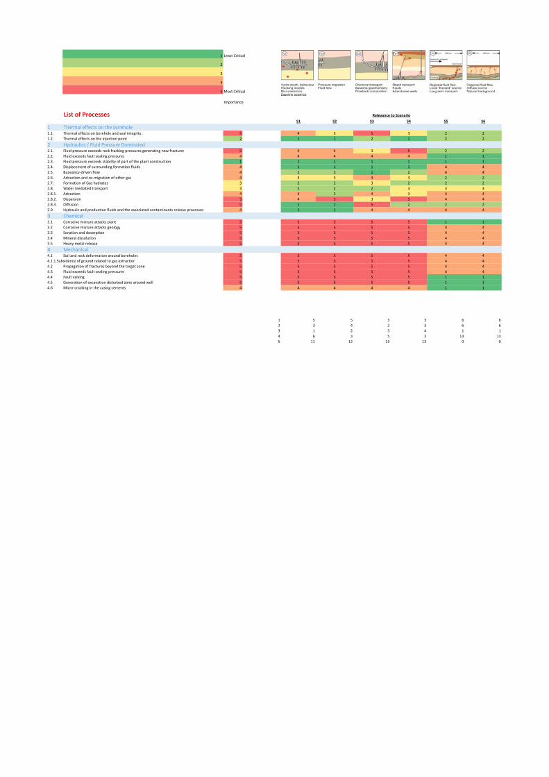
1 Least Critical
2
3
4
5 Most Critical
Importance
List of ProcessesS1 S2 S3 S4 S5 S6
1 Thermal effects on the borehole 1.1. Thermal effects on borehole and seal integrity. 5 4 3 5 3 2 2
1.2. Thermal effects on the injection point 2 1 1 2 1 2 2
2 Hydraulics / Fluid Pressure Dominated2.1. Fluid pressure exceeds rock fracking pressures generating new fractures 5 4 4 3 5 2 2
2.2. Fluid exceeds fault sealing pressures 4 4 4 4 4 1 1
2.3. Fluid pressure exceeds stability of part of the plant construction. 1 1 1 1 1 1 1
2.4. Displacement of surrounding formation fluids 4 1 1 1 1 4 4
2.5. Buoyancy‐driven flow 4 2 2 1 2 4 4
2.6. Advection and co‐migration of other gas 4 3 3 4 3 2 2
2.7. Formation of Gas hydrates 3 2 2 3 2 2 2
2.8. Water mediated transport 3 2 2 2 3 3 3
2.8.1. Advection 4 4 2 4 3 4 4
2.8.2. Dispersion 5 4 5 3 5 4 4
2.8.3. Diffusion 5 1 1 5 2 2 2
2.9. Hydraulic and production fluids and the associated contaminants release processes 4 1 1 4 4 4 4
3 Chemical3.1 Corrosive mixture attacks plant 5 5 5 5 5 1 1
3.2 Corrosive mixture attacks geology 5 5 5 5 5 4 4
3.3 Sorption and desorption 5 5 5 5 5 4 4
3.4 Mineral dissolution 5 5 5 5 5 4 4
3.5 Heavy metal release 5 5 5 5 5 4 4
4 Mechanical4.1 Soil and rock deformation around boreholes 5 5 5 5 5 4 4
4.1.1 Subsidence of ground related to gas extraction 5 5 5 5 5 4 4
4.2 Propagation of fractures beyond the target zone 5 5 5 5 5 4 4
4.3 Fluid exceeds fault sealing pressures 5 5 5 5 5 4 4
4.4 Fault valving 5 5 5 5 5 1 1
4.5 Generation of excavation disturbed zone around well 5 5 5 5 5 1 1
4.6 Micro‐cracking in the casing cements 4 4 4 4 4 1 1
1 5 5 3 3 6 6
2 3 4 2 3 6 6
3 1 2 3 4 1 1
4 6 3 5 3 13 13
5 11 12 13 13 0 0
Relevance to Scenario