
Technical feasibility study: Supported reach of 100Mbit/s ...

Mitsubishi Electric Automation | Inverters 1Selection Guide Edition 19 • Revised April 1, 2019
FR-A800-E SeriesThe FR-A800-E adds an integrated web server and 100Mbit Ethernet TCP/IP connectivity as standard to the existing network options of the FR-A800 flagship multi-use inverter. The FR-A800-E provides machine builders and systems integrators an increased ability for remote system monitoring and parameter adjustment, as well as easy integration into existing network environments.
• High Speed Response: With a speed response of50Hz, FR-A800 to respond to a change in motorload. FR-A800 reacts to a speed signal much fastertoo – between 2 to 3 ms as opposed to 5 to 20 mswith FR-A700.
• Wide Speed Range: 200:1 speed range open loop,1500:1 closed loop speed range.
• Extended Maximum Speed: A standard FR-A800VFD can drive high speed motors at up to 590Hz,compared to the FR-A700’s 400Hz.
• IPM Motor Control: Standard FR-A800 VFDs candrive the new generation IPM (Internal PermanentMagnet) motors, such as the Marathon ‘SyMAX’Series.
• Safety Stop: FR-A800 is a SAFETY drive. “STO”capability enables SIL2 / PLd category emergencystops.
• Compatible with USB Stick: VFD settings can beeasily uploaded or downloaded and ‘black box’operating data at the time of a drive trip can becopied for diagnosis using the FR-Configuratorsoftware.
• GOT Interface: Automatic connectivity to GOT2000 series GOTs without the need to change anyparameters.
• Improved PLC: FR-A800 has a new internal PLCbased around the Mitsubishi Electric ‘L Series’processor. Instructions in the form of ‘FunctionBlocks’ can now be used.
• Conformal Coating: All FR-A800 VFDs haveConformal Coated boards as standard.
• Separate Rectifier Stage: For drives over 500 HP– greater system flexibility.
• Ethernet Communications as Standard –Communicate with MODBUS TCP/IP or CC-Link IEField Basic communications networks at a speed of100Mbps without the need for an extra option card.
• Automatic IP Address Detection – Automaticallydetect the IP address of all connected drives,quickly enabling connection and programmingusing FR-Configurator2 software.
• Multiple Protocol Capability – Network optioncards offer connection to other drive basednetworks and a higher level information system.
• Drive to Drive Communications – Utilize theinternal PLC to communicate without a master PLCcontroller allowing the drives to work together asa team.
FR-A800-E Ratings 240V Class
Model NumberAMPS for Duty Horsepower For Duty (NEC) Frame
Size Weight Cooling Method
Protective Rating
Regen. Braking Torque / Duty Using Standard Brake Resistors Where Supplied
Stocked ItemSLD LD ND HD SLD LD ND HD
FR-A820-00046-E1N6 4.6 4.2 3 1.5 1 0.75 0.25 A 5.5 Self- Cooling
NEMA 1, UL-1, Plenum Rated (IP20)
150% torque / 3% EDS
FR-A820-00077-E1N6 7.7 7 5 3 2 1 0.5 B 5.9 SFR-A820-00105-E1N6 10.5 9.6 8 5 3 2 1 C 8.8
Forced Air Cooling
SFR-A820-00167-E1N6 16.7 15.2 11 8 5 3 2 C 8.8
100% torque / 3% EDS
FR-A820-00250-E1N6 25 23 17.5 11 7.5 5 3 C 8.8 SFR-A820-00340-E1N6 34 31 24 17.5 10 7.5 5 D 16.7
100% torque / 2% EDS
FR-A820-00490-E1N6 49 45 33 24 20 15 10 7.5 D 16.7 SFR-A820-00630-E1N6 63 58 46 33 20 15 10 E 20.5
20% torque / 100% ED (Brake transistor included)
SFR-A820-00770-E1N6 77 70.5 61 46 25 20 15 F 37.4 SFR-A820-00930-E1N6 93 85 76 61 30 25 20 F 37.4 SFR-A820-01250-E1N6 125 114 90 76 40 30 25 F 37.4 SFR-A820-01540-E160 154 140 115 90 60 50 40 30 G 48.4
IP00
20% torque / 100% ED (Use FR-BU2 brake unit for higherratings)
SFR-A820-01870-E160 187 170 145 115 60 50/60 40 H 92.4 SFR-A820-02330-E160 233 212 175 145 75 60 50 H 92.4 SFR-A820-03160-E160 (*1) 316 288 215 175 125 100 75 60 K 118.8 SFR-A820-03800-E1U6 (*1) 380 346 288 215 150 125 100 75 L 162.8 SFR-A820-04750-E1U6 (*1) 475 432 346 288 150 125 100 L 162.8 S
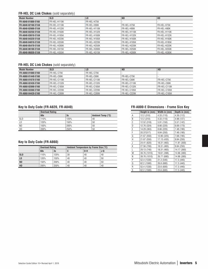
FR-HEL DC Link Chokes (sold separately)Model Number SLD LD ND HD
FR-A820-03160-E160 FR-HEL-90K FR-HEL-75K - -FR-A820-03800-E1U6 FR-HEL-110K FR-HEL-90K FR-HEL-75K -
FR-A820-04750-E1U6 FR-HEL-110K FR-HEL-110K FR-HEL-90K FR-HEL-75K
Note 1: These drives must be used together with a DC Link Choke, sold separately.SLD- 110% 60s, 120% 3s (inverse-time characteristics) at ambient temperature 40°C LD- 120% 60s, 150% 3s (inverse-time characteristics) at ambient temperature 50°C ND- 150% 60s, 200% 3s (inverse-time characteristics) at ambient temperature 50°C HD- 200% 60s, 250% 3s (inverse-time characteristics) at ambient temperature 50°C

2
n I
NVER
TERS
Selection Guide Edition 19 • Revised April 1, 2019
FR-A800-E Ratings 480V Class
Model NumberAMPS For Duty Horsepower For Duty (NEC)
FrameSize
Weight(lbs) (*4)
Cooling Method
Protective Rating
Regen.Braking Torque / Duty (Using Standard Brake Resistors Where Supplied)
Stocked Item
SLD LD ND HD SLD LD ND HD
FR-A840-00023-E1N6 2.3 2.1 1.5 0.8 1 1 0.5 0.25
C
7.7Self-Cooling
NEMA 1, UL-1,Plenum Rated(IP20)
100% torque / 2% ED
S
FR-A840-00038-E1N6 3.8 3 2.5 1.5 2 2 1 0.5 7.7 S
FR-A840-00052-E1N6 5.2 4.8 4 2.5 3 3 2 1 7.7 S
FR-A840-00083-E1N6 8.3 7.6 6 4 5 5 3 2 8.8
Forced AirCooling
S
FR-A840-00126-E1N6 12.6 11.5 9 6 7.5 7.5 5 3 8.8 S
FR-A840-00170-E1N6 17 16 12 9 10 10 7.5 5D
16.7 S
FR-A840-00250-E1N6 25 23 17 12 15 15 10 7.5 16.7 S
FR-A840-00310-E1N6 31 29 23 17 20 20 15 10E
20.5
20% torque / 100% ED (Brake transistor included)
S
FR-A840-00380-E1N6 38 35 31 23 25 25 20 15 20.5 S
FR-A840-00470-E1N6 47 43 38 31 30 30 25 20F
37.4 S
FR-A840-00620-E1N6 62 57 44 38 40 40 30 25 37.4 S
FR-A840-00770-E160 77 70 57 44 60 50 40 30 G 50.6
IP00
S
FR-A840-00930-E160 93 85 71 57 60 60 50 40H
90.2 S
FR-A840-01160-E160 116 106 86 71 75 75 60 50 90.2 S
FR-A840-01800-E160 (*1) 180 144 110 86 150 100 75 60 94.6 S
FR-A840-02160-E1U6 (*1) 216 180 144 110 150 150 100 75J
114.4
10% torque / 100% ED (Use FR-BU2-H for higher ratings)
S
FR-A840-02600-E1U6 (*1) 260 216 180 144 200 150 150 100 121.0 S
FR-A840-03250-E1U6 (*1) 325 260 216 180 250 200 150 150L
156.2 S
FR-A840-03610-E1U6 (*1) 361 325 260 216 300 250 200 150 171.6 S
FR-A840-04320-E1U6 (*1) 432 361 325 260 350 300 250 200M
257.4 S
FR-A840-04810-E1U6 (*1) 481 432 361 325 400 350 300 250 257.4 S
FR-A840-05470-E1U6 (*1) 547 481 432 361 450 400 350 300N
365.2 S
FR-A840-06100-E1U6 (*1) 610 547 481 432 500 450 400 350 365.2 S
FR-A840-06830-E1U6 (*1) 683 610 547 481 550 500 450 400 365.2 S
FR-A842-07700-E1U6 + FR-CC2-H315K-60 (*2) - - 610 547 - - 500 450
P+R
820.6 - (*3)
FR-A842-08660-E1U6 + FR-CC2-H315K-60 (*2) - - - 610 - - - 500 820.6 - (*3)
FR-A842-07700-E1U6 + FR-CC2-H355K-60 (*2) - 683 - - - 550 - - 827.2 - (*3)
FR-A842-08660-E1U6 + FR-CC2-H355K-60 (*2) - - 683 - - - 550 - 827.2 - (*3)
FR-A842-09620-E1U6 + FR-CC2-H355K-60 (*2) - - - 683 - - - 550 Q+R 1003.2 - (*3)
FR-A842-07700-E1U6 + FR-CC2-H400K-60 (*2) 770 - - - 650 - - -
P+S979 - (*3)
FR-A842-08660-E1U6 + FR-CC2-H400K-60 (*2) - 770 - - - 650 - - 979 - (*3)
FR-A842-09620-E1U6 + FR-CC2-H400K-60 (*2) - - 770 - - - 650 -
Q+S1155 - (*3)
FR-A842-10940-E1U6 + FR-CC2-H400K-60 (*2) - - - 770 - - - 650 1155 - (*3)
FR-A842-08660-E1U6 + FR-CC2-H450K-60 (*2) 866 - - - 700 - - - P+S 986 - (*3)
FR-A842-09620-E1U6 + FR-CC2-H450K-60 (*2) - 866 - - - 700 - -
Q+S
1162 - (*3)
FR-A842-10940-E1U6 + FR-CC2-H450K-60 (*2) - - 866 - - - 700 - 1162 - (*3)
FR-A842-12120-E1U6 + FR-CC2-H450K-60 (*2) - - - 866 - - - 700 1162 - (*3)
FR-A842-09620-E1U6 + FR-CC2-H500K-60 (*2) 962 - - - 800 - - - 1168 - (*3)
FR-A842-10940-E1U6 + FR-CC2-H500K-60 (*2) - 962 - - - 800 - - 1168 - (*3)
FR-A842-12120-E1U6 + FR-CC2-H500K-60 (*2) - - 962 - - - 800 - 1168 - (*3)
FR-A842-10940-E1U6 + FR-CC2-H560K-60 (*2) 1094 - - - 900 - - - 1179 - (*3)
FR-A842-12120-E1U6 + FR-CC2-H560K-60 (*2) - 1094 - - - 900 - - 1179 - (*3)
FR-A842-12120-E1U6 + FR-CC2-H630K-60 (*2) 1212 - - - 1000 - - - 1181 - (*3)
Notes:1. These drives must be used with DC Link Chokes (sold separately).2. Drives are "sectional" design, used together with FR-CC2 rectifier stage.3. Consult VFD Marketing for availability.4. For FR-A842 and FR-CC2 combinations, the weights are COMBINED. Drives in shaded area MUST be used together with FR-HEL DC Link Choke (sold separately).
Mitsubishi Electric Automation | Inverters 3Selection Guide Edition 19 • Revised April 1, 2019
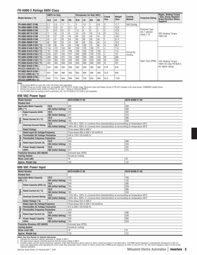
690 VAC Power InputModel Number A870-02300-E1-60 A870-02860-E1-60Stocked Item - -Applicable Motor Capacity (kW) (*1)
SLD 200 250ND (Initial Setting) 160 200
Outp
ut
Rated Capacity (kVA) (*2)
SLD 275 342ND (Initial Setting) 221 275
Rated Current (A (*3)SLD 230 286ND (Initial Setting) 185 230
Overload Current Rating SLD 110% 60 s, 120% 3 s (inverse-time characteristics) at surrounding air temperature 40°CND (Initial Setting) 150% 60 s, 200% 3 s (inverse-time characteristics) at surrounding air temperature 40°C
Rated Voltage Three-phase 600 to 690 V
Pow
er S
uppl
y
Rated input AC Voltage/Frequency Three-phase 600 to 690 V 50 Hz/60 HzPermissible AC Voltage Fluctuation 540 to 759 V 50 Hz/60 HzPermissible Frequency Fluctuation ±5%
Rated Input Current (A)SLD 230 286ND (Initial Setting) 185 230
Power Supply Capacity (kVA)
SLD 275 342ND (Initial Setting) 221 275
Protective Structure (IEC 60529) Enclosed type (IP20)Cooling System Forced air coolingNoise Level (dB) 79 79Approx. Weight (kg) 120 122
600 VAC Power InputModel Number A870-02300-E1-60 A870-02300-E1-60Stocked Item - -Applicable Motor Capacity (kW) (*1)
SLD 132 160ND (Initial Setting) 110 132
Outp
ut
Rated Capacity (kVA) (2)SLD 229 285ND (Initial Setting) 184 229
Rated Current (A (*3)SLD 230 286ND (Initial Setting) 185 230
Overload Current Rating SLD 110% 60 s, 120% 3 s (inverse-time characteristics) at surrounding air temperature 40°CND (Initial Setting) 150% 60 s, 200% 3 s (inverse-time characteristics) at surrounding air temperature 40°C
Rated Voltage (*5) Three-phase 525 to 600 V
Pow
er S
uppl
y
Rated input AC Voltage/Frequency Three-phase 525 to 600 V 50 Hz/60 HzPermissible AC Voltage Fluctuation 472 to 660 V 50 Hz/60 HzPermissible Frequency Fluctuation ±5%
Rated Input Current (A) SLD 230 286ND (Initial Setting) 185 230
Power Supply Capacity (kVA)
SLD 229 285ND (Initial Setting) 184 229
Protective Structure (IEC 60529) Enclosed type (IP20)Cooling System Forced air coolingNoise Level (dB) 79 79Approx. Weight (kg) 120 122
Notes: See User Manual for detailed information.1. Indicates the maximum capacity applicable to voltage of 690 V.2. The rated output capacity indicated assumes that the output voltage is 690 V.3. Possible output currents during continuous operation under Real sensorless vector control or Vector control are shown in the table below. The PWM carrier frequency is automatically decreased to 2 kHz for
heavy duty applications when operating the motor under Real sensorless vector control or Vector control with a PWM carrier frequency of 6 kHz or more (Pr.72 ≥ 6). The carrier frequency stays at 4 kHz in fast response operation.
FR-A800-E Ratings 600V Class
Model Number (*4)AMPS for Duty Horsepower for Duty (NEC)
Frame Size
Weight (lbs)
Cooling Method Protective Rating
Regen. Braking Torque / Duty (Using Standard Brake Resistors Where SuppliedSLD LD ND HD SLD LD ND HD
FR-A860-00027-E1N6 2.7 2.5 1.7 1 2 1.5 1 0.5 C 11.7 Self Cooling
Enclosed Type (UL-1 plenum rated) (*3) 20% Braking Torque
100% ED
FR-A860-00061-E1N6 6.1 5.6 4 2.7 5 3 3 2 C 12.8
Forced Air Cooling
FR-A860-00090-E1N6 9 8.2 6.1 4 7.5 5 5 3 C 12.8FR-A860-00170-E1N6 17 16 12 9 15 10 10 7.5 D 15.4FR-A860-00320-E1N6 32 27 22 16 30 25 20 10 E 19.8FR-A860-00450-E1N6 45 41 33 24 40 40 30 20 F 37.4FR-A860-00680-E160 68 62 55 41 60 60 50 40 H 79.2
Open Type (IP00)
FR-A860-01080-E160 (*1) 108 99 84 63 100 100 75 60 H 90.2FR-A860-01440-E160 (*1) 144 131 104 84 150 125 100 75 J 114
10% Braking Torque 100% ED (Use FR-BU2-C for higher rating)
FR-A860-01670-E160 (*1) 167 152 131 104 150 150 125 100 J 114FR-A860-02430-E160 (*1) 243 221 152 131 250 200 150 125 J 121FR-A860-02890-E160 (*1) 289 255 221 152 300 250 200 150 M 246FR-A860-03360-E160 (*1) 336 304 255 202 350 300 250 200 M 253FR-A860-04420-E160 (*1) 442 402 304 255 450 400 300 250 N 337FR-A862-05450-E160 + FR-CC2-C355K-60 (*2) 545 496 402 304 550 500 400 300 P+R 810
FR-A862-06470-E160 + FR-CC2-C400K-60 (*2) 647 589 496 402 650 600 500 400 Q+S 920
FR-A862-08500-E160 + FR-CC2-C560K-60 (*2) 850 773 663 589 850 750 650 600 Q+S 1126
Notes:1. These drives MUST be used with a DC Link Choke (sold separately).2. FR-A862 Drives are inverter stage only; use together with FR-CC2-C rectifier stage. Maximum Input and Output Current of FR-CC2 modules is the value shown. COMBINED weight shown.3. Remove the standard brake resistor (if fitted) for UL type 1. Rating is otherwise NEMA 1.4. The FR-A860 does not include a built in parameter unit. The FR-DU08 or FR-LU08 is sold separately.
4
n I
NVER
TERS
Selection Guide Edition 19 • Revised April 1, 2019
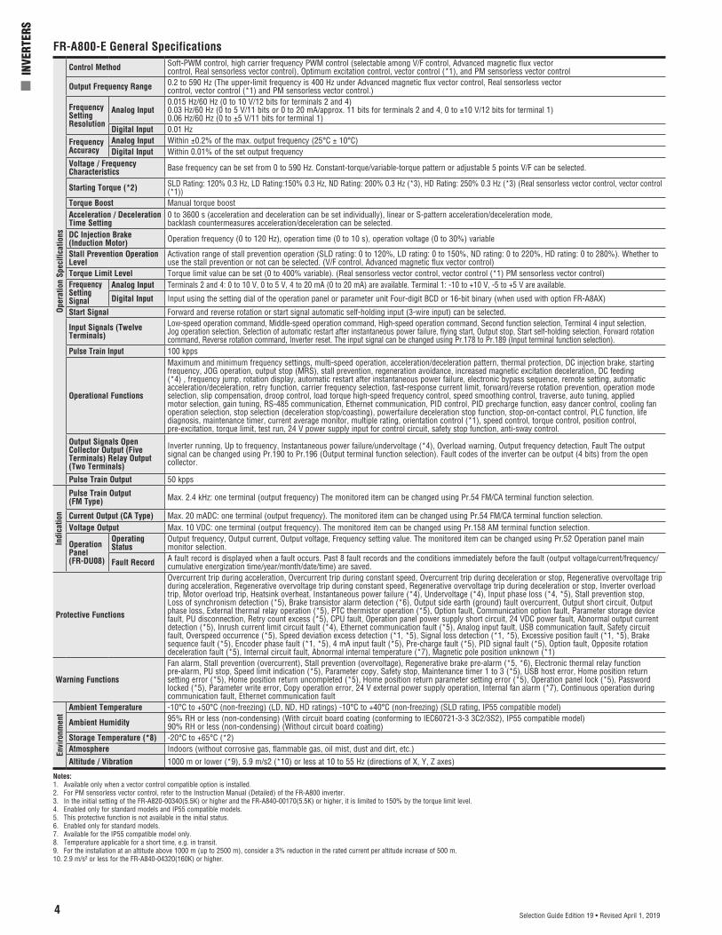
FR-A800-E General SpecificationsOp
erat
ion
Spec
ifica
tions
Control Method Soft-PWM control, high carrier frequency PWM control (selectable among V/F control, Advanced magnetic flux vectorcontrol, Real sensorless vector control), Optimum excitation control, vector control (*1), and PM sensorless vector control
Output Frequency Range 0.2 to 590 Hz (The upper-limit frequency is 400 Hz under Advanced magnetic flux vector control, Real sensorless vectorcontrol, vector control (*1) and PM sensorless vector control.)
Frequency Setting Resolution
Analog Input0.015 Hz/60 Hz (0 to 10 V/12 bits for terminals 2 and 4)0.03 Hz/60 Hz (0 to 5 V/11 bits or 0 to 20 mA/approx. 11 bits for terminals 2 and 4, 0 to ±10 V/12 bits for terminal 1)0.06 Hz/60 Hz (0 to ±5 V/11 bits for terminal 1)
Digital Input 0.01 HzFrequency Accuracy
Analog Input Within ±0.2% of the max. output frequency (25°C ± 10°C)Digital Input Within 0.01% of the set output frequency
Voltage / Frequency Characteristics Base frequency can be set from 0 to 590 Hz. Constant-torque/variable-torque pattern or adjustable 5 points V/F can be selected.
Starting Torque (*2) SLD Rating: 120% 0.3 Hz, LD Rating:150% 0.3 Hz, ND Rating: 200% 0.3 Hz (*3), HD Rating: 250% 0.3 Hz (*3) (Real sensorless vector control, vector control (*1))
Torque Boost Manual torque boost Acceleration / Deceleration Time Setting
0 to 3600 s (acceleration and deceleration can be set individually), linear or S-pattern acceleration/deceleration mode,backlash countermeasures acceleration/deceleration can be selected.
DC Injection Brake (Induction Motor) Operation frequency (0 to 120 Hz), operation time (0 to 10 s), operation voltage (0 to 30%) variable
Stall Prevention Operation Level
Activation range of stall prevention operation (SLD rating: 0 to 120%, LD rating: 0 to 150%, ND rating: 0 to 220%, HD rating: 0 to 280%). Whether to use the stall prevention or not can be selected. (V/F control, Advanced magnetic flux vector control)
Torque Limit Level Torque limit value can be set (0 to 400% variable). (Real sensorless vector control, vector control (*1) PM sensorless vector control)Frequency Setting Signal
Analog Input Terminals 2 and 4: 0 to 10 V, 0 to 5 V, 4 to 20 mA (0 to 20 mA) are available. Terminal 1: -10 to +10 V, -5 to +5 V are available.
Digital Input Input using the setting dial of the operation panel or parameter unit Four-digit BCD or 16-bit binary (when used with option FR-A8AX)
Start Signal Forward and reverse rotation or start signal automatic self-holding input (3-wire input) can be selected.
Input Signals (Twelve Terminals)
Low-speed operation command, Middle-speed operation command, High-speed operation command, Second function selection, Terminal 4 input selection, Jog operation selection, Selection of automatic restart after instantaneous power failure, flying start, Output stop, Start self-holding selection, Forward rotation command, Reverse rotation command, Inverter reset. The input signal can be changed using Pr.178 to Pr.189 (Input terminal function selection).
Pulse Train Input 100 kpps
Operational Functions
Maximum and minimum frequency settings, multi-speed operation, acceleration/deceleration pattern, thermal protection, DC injection brake, starting frequency, JOG operation, output stop (MRS), stall prevention, regeneration avoidance, increased magnetic excitation deceleration, DC feeding (*4) , frequency jump, rotation display, automatic restart after instantaneous power failure, electronic bypass sequence, remote setting, automatic acceleration/deceleration, retry function, carrier frequency selection, fast-response current limit, forward/reverse rotation prevention, operation mode selection, slip compensation, droop control, load torque high-speed frequency control, speed smoothing control, traverse, auto tuning, applied motor selection, gain tuning, RS-485 communication, Ethernet communication, PID control, PID precharge function, easy dancer control, cooling fan operation selection, stop selection (deceleration stop/coasting), powerfailure deceleration stop function, stop-on-contact control, PLC function, life diagnosis, maintenance timer, current average monitor, multiple rating, orientation control (*1), speed control, torque control, position control, pre-excitation, torque limit, test run, 24 V power supply input for control circuit, safety stop function, anti-sway control.
Output Signals Open Collector Output (Five Terminals) Relay Output (Two Terminals)
Inverter running, Up to frequency, Instantaneous power failure/undervoltage (*4), Overload warning, Output frequency detection, Fault The output signal can be changed using Pr.190 to Pr.196 (Output terminal function selection). Fault codes of the inverter can be output (4 bits) from the open collector.
Pulse Train Output 50 kpps
Indi
catio
n
Pulse Train Output (FM Type) Max. 2.4 kHz: one terminal (output frequency) The monitored item can be changed using Pr.54 FM/CA terminal function selection.
Current Output (CA Type) Max. 20 mADC: one terminal (output frequency). The monitored item can be changed using Pr.54 FM/CA terminal function selection.Voltage Output Max. 10 VDC: one terminal (output frequency). The monitored item can be changed using Pr.158 AM terminal function selection.
Operation Panel (FR-DU08)
Operating Status
Output frequency, Output current, Output voltage, Frequency setting value. The monitored item can be changed using Pr.52 Operation panel main monitor selection.
Fault Record A fault record is displayed when a fault occurs. Past 8 fault records and the conditions immediately before the fault (output voltage/current/frequency/cumulative energization time/year/month/date/time) are saved.
Protective Functions
Overcurrent trip during acceleration, Overcurrent trip during constant speed, Overcurrent trip during deceleration or stop, Regenerative overvoltage trip during acceleration, Regenerative overvoltage trip during constant speed, Regenerative overvoltage trip during deceleration or stop, Inverter overload trip, Motor overload trip, Heatsink overheat, Instantaneous power failure (*4), Undervoltage (*4), Input phase loss (*4, *5), Stall prevention stop, Loss of synchronism detection (*5), Brake transistor alarm detection (*6), Output side earth (ground) fault overcurrent, Output short circuit, Output phase loss, External thermal relay operation (*5), PTC thermistor operation (*5), Option fault, Communication option fault, Parameter storage device fault, PU disconnection, Retry count excess (*5), CPU fault, Operation panel power supply short circuit, 24 VDC power fault, Abnormal output current detection (*5), Inrush current limit circuit fault (*4), Ethernet communication fault (*5), Analog input fault, USB communication fault, Safety circuit fault, Overspeed occurrence (*5), Speed deviation excess detection (*1, *5), Signal loss detection (*1, *5), Excessive position fault (*1, *5), Brake sequence fault (*5), Encoder phase fault (*1, *5), 4 mA input fault (*5), Pre-charge fault (*5), PID signal fault (*5), Option fault, Opposite rotation deceleration fault (*5), Internal circuit fault, Abnormal internal temperature (*7), Magnetic pole position unknown (*1)
Warning Functions
Fan alarm, Stall prevention (overcurrent), Stall prevention (overvoltage), Regenerative brake pre-alarm (*5, *6), Electronic thermal relay function pre-alarm, PU stop, Speed limit indication (*5), Parameter copy, Safety stop, Maintenance timer 1 to 3 (*5), USB host error, Home position return setting error (*5), Home position return uncompleted (*5), Home position return parameter setting error (*5), Operation panel lock (*5), Password locked (*5), Parameter write error, Copy operation error, 24 V external power supply operation, Internal fan alarm (*7), Continuous operation during communication fault, Ethernet communication fault
Envi
ronm
ent
Ambient Temperature -10°C to +50°C (non-freezing) (LD, ND, HD ratings) -10°C to +40°C (non-freezing) (SLD rating, IP55 compatible model)
Ambient Humidity 95% RH or less (non-condensing) (With circuit board coating (conforming to IEC60721-3-3 3C2/3S2), IP55 compatible model)90% RH or less (non-condensing) (Without circuit board coating)
Storage Temperature (*8) -20°C to +65°C (*2)Atmosphere Indoors (without corrosive gas, flammable gas, oil mist, dust and dirt, etc.)Altitude / Vibration 1000 m or lower (*9), 5.9 m/s2 (*10) or less at 10 to 55 Hz (directions of X, Y, Z axes)
Notes:1. Available only when a vector control compatible option is installed.2. For PM sensorless vector control, refer to the Instruction Manual (Detailed) of the FR-A800 inverter.3. In the initial setting of the FR-A820-00340(5.5K) or higher and the FR-A840-00170(5.5K) or higher, it is limited to 150% by the torque limit level.4. Enabled only for standard models and IP55 compatible models.5. This protective function is not available in the initial status.6. Enabled only for standard models.7. Available for the IP55 compatible model only.8. Temperature applicable for a short time, e.g. in transit.9. For the installation at an altitude above 1000 m (up to 2500 m), consider a 3% reduction in the rated current per altitude increase of 500 m.10. 2.9 m/s² or less for the FR-A840-04320(160K) or higher.
Mitsubishi Electric Automation | Inverters 5Selection Guide Edition 19 • Revised April 1, 2019
Model Number SLD LD ND HDFR-A860-01080-E160 FR-HEL-C75K FR-HEL-C75K - -FR-A860-01440-E160 FR-HEL-C90K FR-HEL-C90K FR-HEL-C75K -FR-A860-01670-E160 FR-HEL-C110K FR-HEL-C110K FR-HEL-C90K FR-HEL-C75KFR-A860-02430-E160 FR-HEL-C132K FR-HEL-C132K FR-HEL-C110K FR-HEL-C90KFR-A860-02890-E160 FR-HEL-C185K FR-HEL-C185K FR-HEL-C132K FR-HEL-C110KFR-A860-03360-E160 FR-HEL-C220K FR-HEL-C220K FR-HEL-C185K FR-HEL-C185KFR-A860-04420-E160 FR-HEL-C280K FR-HEL-C280K FR-HEL-C220K FR-HEL-C185K
Key to Duty Code (FR-A820, FR-A840)Overload Rating60s 3s Ambient Temp (°C)
SLD 110% 120% 40LD 120% 150% 50ND 150% 200% 50HD 200% 250% 50
FR-HEL DC Link Chokes (sold separately)
FR-A800-E Dimensions - Frame Size KeyHeight-in (mm) Width-in (mm) Depth-in (mm)
A 12.2 (310) 4.33 (110) 4.39 (112)B 12.2 (310) 4.33 (110) 4.98 (127)C 12.52 (318) 5.91 (150) 5.57 (142)D 12.76 (324) 8.66 (220) 6.69 (170)E 14.29 (363) 8.66 (220) 7.48 (190)F 20.37(517) 9.84 (250) 7.48 (190)G 21.67 (550) 12.80 (325) 7.68 (195)H 21.67 (550) 17.13 (435) 9.84 (250)J 24.41 (620) 18.31 (465) 11.81 (300)K 27.56 (700) 18.31 (465) 9.84 (250)L 29.13 (740) 18.31 (465) 14.17 (360)M 39.76 (1010) 19.61 (498) 14.96 (380)N 39.76 (1010) 26.77 (680) 14.96 (380)P 52.4 (1330) 21.3 (540) 17.3 (440)Q 62.2 (1580) 26.8 (680) 17.3 (440)R 52.4 (1330) 23.6 (600) 17.3 (440)S 62.2 (1580) 23.6 (600) 17.3 (440)
Model Number SLD LD ND HDFR-A840-01800-E160 FR-HEL-H110K FR-HEL-H75K - -FR-A840-02160-E1U6 FR-HEL-H110K FR-HEL-H90K FR-HEL-H75K FR-HEL-H75KFR-A840-02600-E1U6 FR-HEL-H132K FR-HEL-H110K FR-HEL-H90K FR-HEL-H90KFR-A840-03250-E1U6 FR-HEL-H160K FR-HEL-H132K FR-HEL-H110K FR-HEL-H110KFR-A840-03610-E1U6 FR-HEL-H185K FR-HEL-H160K FR-HEL-H132K FR-HEL-H132KFR-A840-04320-E1U6 FR-HEL-H220K FR-HEL-H185K FR-HEL-H160K FR-HEL-H160KFR-A840-04810-E1U6 FR-HEL-H250K FR-HEL-H220K FR-HEL-H185K FR-HEL-H185KFR-A840-05470-E1U6 FR-HEL-H280K FR-HEL-H250K FR-HEL-H220K FR-HEL-H220KFR-A840-06100-E1U6 FR-HEL-H315K FR-HEL-H280K FR-HEL-H250K FR-HEL-H250KFR-A840-06830-E1U6 FR-HEL-H355K FR-HEL-H315K FR-HEL-H280K FR-HEL-H280K
FR-HEL DC Link Chokes (sold separately)
Key to Duty Code (FR-A860)Overload Rating Ambient Temperature by Frame Size (°C)60s 3s C D-H J-Q
SLD 110% 120% 30 40 40LD 120% 150% 40 40 50ND 150% 200% 40 40 50HD 200% 250% 40 40 40
6
n I
NVER
TERS
Selection Guide Edition 19 • Revised April 1, 2019
FR-A800-E Dynamic BrakingAll Mitsubishi Electric VFDs have some inherent braking capability. During controlled deceleration, motor regenerative losses are dissipated in the motor, wire, and VFD circuitry. The built-in DC injection braking allows for low speed braking and stopping. When the above capabilities are inadequate for an application, it is necessary to add a power transistor brake unit and resistor unit in series across the DC bus. Motor regeneration causes the DC bus voltage to increase, and when the voltage exceeds a specified threshold, the transistor turns on to pass current through the resistor. Motor kinetic energy is converted to heat energy. VFD overcurrent and overvoltage protective circuits are active at all times, and will fault-trip the VFD if the brake size is inadequate. Two main factors must be considered when sizing the brake, the effective duty cycle (%ED) and the short time duty rating. The effective duty cycle is increased when an external resistor is added. It is preferable to profile the effective duty cycle of the units of time. With this information, the short time duty is known and the %ED can be calculated, as shown in the following example. %ED = Braking time / total time for complete operating cycle x 100Example: In a given application a load is accelerated for 5 seconds, runs for 60 seconds and decelerates in 3 seconds before resting for 12 seconds.%ED = 3 / (5 + 60 + 3 + 12) x 100 = 3.6%The tables shown assume 100% brake torque, when brake torque is represented by its percentage to the rated torque of the applied motor.Torque (kg.m) = 974 x Power (kW) / Speed (rpm).
FR-A800-E Fitted with Internal Brake Resistor – Torque and Duty Cycle Figure
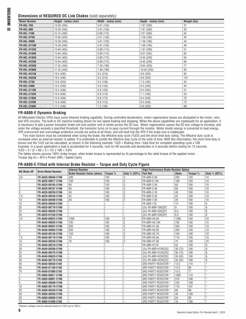
Dimensions of REQUIRED DC Link Chokes (sold separately)Model Number Height - inches (mm) Width - inches (mm) Depth - inches (mm) Weight (lbs)FR-HEL-75K 13.39 (340) 5.91 (150) 7.87 (200) 37FR-HEL-90K 13.39 (340) 5.91 (150) 7.87 (200) 42FR-HEL-110K 15.75 (400) 6.89 (175) 7.87 (200) 44FR-HEL-H75K 12.60 (320) 5.51 (140) 7.28 (185) 35FR-HEL-H90K 13.39 (340) 5.91 (150) 7.48 (190) 44FR-HEL-H110K 13.39 (340) 5.91 (150) 7.68 (195) 48FR-HEL-H132K 15.94 (405) 6.89 (175) 7.87 (200) 57FR-HEL-H160K 15.94 (405) 6.89 (175) 8.07 (205) 62FR-HEL-H185K 15.94 (405) 6.89 (175) 9.45 (240) 64FR-HEL-H220K 15.94 (405) 6.89 (175) 9.45 (240) 66FR-HEL-H250K 17.32 (440) 7.48 (190) 9.84 (250) 77FR-HEL-H280K 17.32 (440) 7.48 (190) 10.04 (255) 84FR-HEL-H315K 19.5 (495) 8.3 (210) 9.8 (250) 92FR-HEL-H355K 19.5 (495) 8.3 (210) 9.8 (250) 101FR-HEL-C75K 12.6 (320) 5.5 (140) 7.3 (185) 35FR-HEL-C90K 13.3 (340) 5.9 (150) 9.4 (240) 44FR-HEL-C110K 13.3 (340) 5.9 (150) 9.4 (240) 51FR-HEL-C132K 15.9 (405) 6.9 (175) 7.7 (195) 53FR-HEL-C185K 15.9 (405) 6.9 (175) 9.4 (240) 70FR-HEL-C220K 15.9 (405) 6.9 (175) 9.4 (240) 73FR-HEL-C280K 17.3 (440) 7.5 (190) 9.8 (250) 88
ND Mode HP Drive Model NumberInternal Resistor High Performance Brake Resistor OptionBrake Resistor Value (ohms) Torque % Duty % (ED%) Part Ref. Ohms Torque % Duty % (ED%)
3/4 FR-A820-00046-E1N6 200 150 3 FR-ABR-0.4K 200 150 101 FR-A820-00077-E1N6 100 150 3 FR-ABR-0.75K 100 150 102 FR-A820-00105-E1N6 60 150 3 FR-ABR-2.2K 60 100 103 FR-A820-00167-E1N6 60 100 3 FR-ABR-2.2K 60 100 105 FR-A820-00250-E1N6 40 100 3 FR-ABR-3.7K 40 100 107.5 FR-A820-00340-E1N6 25 100 2 FR-ABR-5.5K 25 100 1010 FR-A820-00490-E1N6 20 100 2 FR-ABR-7.5K 20 100 1015 FR-A820-00630-E1N6 - - - FR-ABR-11K 13 100 620 FR-A820-00770-E1N6 - - - (2x) FR-ABR-15K[2P] 9 100 625 FR-A820-00930-E1N6 - - - (2x) FR-ABR-22K[2P] 6.5 100 630 FR-A820-01250-E1N6 - - - (2x) FR-ABR-22K[2P] 6.5 100 61/2 FR-A840-00023-E1N6 1200 100 2 FR-ABR-H0.4K 1200 100 101 FR-A840-00038-E1N6 700 100 2 FR-ABR-H0.75K 700 100 102 FR-A840-00052-E1N6 350 100 2 FR-ABR-H1.5K 350 100 103 FR-A840-00083-E1N6 250 100 2 FR-ABR-H2.2K 250 100 105 FR-A840-00126-E1N6 150 100 2 FR-ABR-H3.7K 150 100 107.5 FR-A840-00170-E1N6 75 100 2 FR-ABR-H5.5K 110 100 1010 FR-A840-00250-E1N6 75 100 2 FR-ABR-H7.5K 75 100 1015 FR-A840-00310-E1N6 - - - FR-ABR-H11K 52 100 620 FR-A840-00380-E1N6 - - - (2x) FR-ABR-H15K[2S] 36 (72) 100 625 FR-A840-00470-E1N6 - - - (2x) FR-ABR-H15K[2S] 36 (72) 100 630 FR-A840-00620-E1N6 - - - (2x) FR-ABR-H22K[2S] 26 (52) 100 640 FR-A840-00770-E160 - - - (2x) FR-ABR-H22K[2S] 26 (52) 100 650 FR-A840-00930-E160 - - - 3RD PARTY RESISTOR * 13.5 115 *60 FR-A840-01160-E160 - - - 3RD PARTY RESISTOR * 13.5 95 *75 FR-A840-01800-E160 - - - 3RD PARTY RESISTOR * 13.5 77 *1 FR-A860-00027-E1N6 - - - 3RD PARTY RESISTOR * 1000 118 *3 FR-A860-00061-E1N6 - - - 3RD PARTY RESISTOR * 370 108 *5 FR-A860-00090-E1N6 - - - 3RD PARTY RESISTOR * 220 108 *10 FR-A860-00170-E1N6 - - - 3RD PARTY RESISTOR * 110 107 *20 FR-A860-00320-E1N6 - - - 3RD PARTY RESISTOR * 60 98 *30 FR-A860-00450-E1N6 - - - 3RD PARTY RESISTOR * 40 100 *50 FR-A860-00680-E160 - - - 3RD PARTY RESISTOR * 24 99 *75 FR-A860-01080-E160 - - - 3RD PARTY RESISTOR * 16 100 *
*Resistor wattage must be selected based on %ED (up to 100%)
Mitsubishi Electric Automation | Inverters 7Selection Guide Edition 19 • Revised April 1, 2019
R1/L11S1/L21
PC
Frequency setting signals (Analog) 10E(+10V)
10(+5V)
2
(Analog common)
23
1
Auxiliaryinput
Terminal 4 input(Current input)
1
4
Frequency settingpotentiometer1/2W1kΩ
Running
Up to frequency
Overload
Frequency detection
Open collector output common Sink/source common
Motor
Relay output 1(Fault output)
C1
B1
A1
UVW
Earth(Ground)
0 to ±5VDC selectable0 to ±10VDC
Open collector output *9
Main circuit terminal
Control circuit terminal
0 to 5VDC0 to 10VDC
C2
B2
A2Relay output 2
Relay output *8
M
0 to 20mADC
0 to 5VDC0 to 10VDC
selectable
4 to 20mADC
SIN
K
SO
UR
CE
*3
*6
*6
*6
*6
Connector for plug-in option connection
STF
STR
STP(STOP)
RH
RM
RL
JOG
RT
MRS X10
RES
AU
CS
SD
RUN
SU
IPF
OL
FU
SE
(+)(-)
5
(+)(-)
Sink logic
*7
Earth (Ground)
N/-
P/+
Initial value
ONOFF
42
For manufacturer
So (SO)
SOC
Shortingwire
S1
S2
PC
SDSIC
+24SD
Jumper*1
Connector 1 Connector 2
Connector 3
24V external powersupply input
Common terminal
24VDC power supply(Common for external power supply transistor)
Forward rotation startReverse rotation start
Start self-holding selection
Middle speed
High speed
Low speed
Jog operation
Second function selection
Reset
Terminal 4 input selection
Control input signals (No voltage input allowed) *2
Multi-speedselection
Contact input common
Main circuit
Control circuit
PUconnector
USB A connector
USBmini Bconnector
Voltage/currentinput switch
selectable
Initial value
Initial value
Output stop RDA
RDI
Converterunit
RSO
SE
N/-
P/+
IPF
RDB
FAN
R/L1S/L2T/L3
OH
RESSD
PC
+24C1
B1
A1
*4
*10
*5
(-)
(+) Analog signal output(0 to ±10VDC)
(-)
(+) Analog current output(0 to 20mADC)
AM
5
F/C(CA)
Ethernet connector
*11
*11
24V
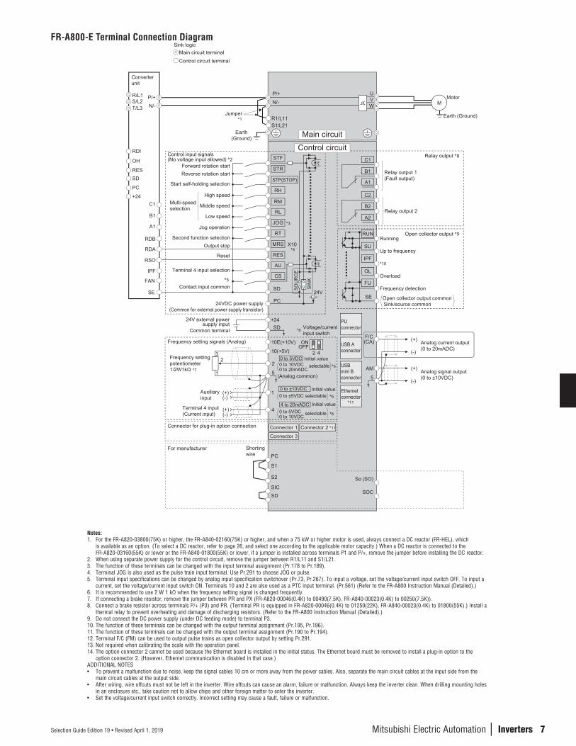
FR-A800-E Terminal Connection Diagram
Notes:1. For the FR-A820-03800(75K) or higher, the FR-A840-02160(75K) or higher, and when a 75 kW or higher motor is used, always connect a DC reactor (FR-HEL), which
is available as an option. (To select a DC reactor, refer to page 26, and select one according to the applicable motor capacity.) When a DC reactor is connected to the FR-A820-03160(55K) or lower or the FR-A840-01800(55K) or lower, if a jumper is installed across terminals P1 and P/+, remove the jumper before installing the DC reactor.
2. When using separate power supply for the control circuit, remove the jumper between R1/L11 and S1/L21.3. The function of these terminals can be changed with the input terminal assignment (Pr.178 to Pr.189).4. Terminal JOG is also used as the pulse train input terminal. Use Pr.291 to choose JOG or pulse.5. Terminal input specifications can be changed by analog input specification switchover (Pr.73, Pr.267). To input a voltage, set the voltage/current input switch OFF. To input a
current, set the voltage/current input switch ON. Terminals 10 and 2 are also used as a PTC input terminal. (Pr.561) (Refer to the FR-A800 Instruction Manual (Detailed).)6. It is recommended to use 2 W 1 kΩ when the frequency setting signal is changed frequently.7. If connecting a brake resistor, remove the jumper between PR and PX (FR-A820-00046(0.4K) to 00490(7.5K), FR-A840-00023(0.4K) to 00250(7.5K)).8. Connect a brake resistor across terminals P/+ (P3) and PR. (Terminal PR is equipped in FR-A820-00046(0.4K) to 01250(22K), FR-A840-00023(0.4K) to 01800(55K).) Install a
thermal relay to prevent overheating and damage of discharging resistors. (Refer to the FR-A800 Instruction Manual (Detailed).)9. Do not connect the DC power supply (under DC feeding mode) to terminal P3.10. The function of these terminals can be changed with the output terminal assignment (Pr.195, Pr.196). 11. The function of these terminals can be changed with the output terminal assignment (Pr.190 to Pr.194).12. Terminal F/C (FM) can be used to output pulse trains as open collector output by setting Pr.291.13. Not required when calibrating the scale with the operation panel.14. The option connector 2 cannot be used because the Ethernet board is installed in the initial status. The Ethernet board must be removed to install a plug-in option to the
option connector 2. (However, Ethernet communication is disabled in that case.)ADDITIONAL NOTES• To prevent a malfunction due to noise, keep the signal cables 10 cm or more away from the power cables. Also, separate the main circuit cables at the input side from the
main circuit cables at the output side.• After wiring, wire offcuts must not be left in the inverter. Wire offcuts can cause an alarm, failure or malfunction. Always keep the inverter clean. When drilling mounting holes
in an enclosure etc., take caution not to allow chips and other foreign matter to enter the inverter.• Set the voltage/current input switch correctly. Incorrect setting may cause a fault, failure or malfunction.
8
n I
NVER
TERS
Selection Guide Edition 19 • Revised April 1, 2019
R1/L11S1/L21
PC
Frequency setting signals (Analog) 10E(+10V)
10(+5V)
2
(Analog common)
23
1
Auxiliaryinput
Terminal 4 input(Current input)
1
4
Frequency settingpotentiometer1/2W1kΩ
Running
Up to frequency
Overload
Frequency detection
Open collector output common Sink/source common
F/C(FM)
SD
Motor
Relay output 1(Fault output)
C1
B1
A1
UVW
Indicator(Frequency meter, etc.)
+ -
(-)
(+) Analog signal output(0 to ±10VDC)
Earth(Ground)
AM
5
0 to ±5VDC selectable0 to ±10VDC
Open collector output ��
Moving-coil type1mA full-scale
Calibrationresistor ���
Main circuit terminal
Control circuit terminal
0 to 5VDC0 to 10VDC
C2
B2
A2Relay output 2
Relay output ��
M
0 to 20mADC
0 to 5VDC0 to 10VDC
selectable
4 to 20mADC
SIN
K
SO
UR
CE
��
��
��
���
��
��
Connector for plug-in option connection
STF
STR
STP(STOP)
RH
RM
RL
JOG
RT
MRS X10
RES
AU
CS
SD
RUN
SU
IPF
OL
FU
SE
(+)(-)
5
(+)(-)
Sink logic
��
Earth (Ground)
N/-
P/+
Initial value
ONOFF
42
Safety stop signal
Safety monitor output
Safety monitor output common
So
SOC
Safety stop input (Channel 1)
Shortingwire
Safety stop input common
Safety stop input (Channel 2)
S1
S2
PC
SDSIC
+24SD
Brake unit(Option)
Jumper��
Connector 1 Connector 2���
Connector 3
24V external powersupply input
Common terminal
24VDC power supply(Common for external power supply transistor)
Forward rotation startReverse rotation start
Start self-holding selection
Middle speed
High speed
Low speed
Jog operation
Second function selection
Reset
Terminal 4 input selectionSelection of automatic restart
after instantaneous power failure
Control input signals (No voltage input allowed) ��
Multi-speedselection
Contact input common
Main circuit
Control circuit
PUconnector
USB A connector
USBmini Bconnector
Ethernetconnector
Voltage/currentinput switch
selectable
Initial value
Initial value
Output stop RDA
RDI
Converterunit
RSO
SE
N/-
P/+
IPF
RDB
FAN
R/L1S/L2T/L3
OH
RESSD
PC
+24C1
B1
A1
��
��
���
24V
24V
Output shutoffcircuit
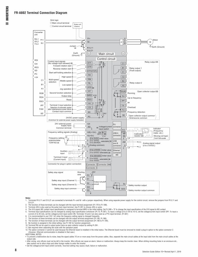
FR-A802 Terminal Connection Diagram
Notes:1. Terminals R1/L11 and S1/L21 are connected to terminals P/+ and N/- with a jumper respectively. When using separate power supply for the control circuit, remove the jumpers from R1/L11 and
S1/L21.2. The function of these terminals can be changed with the input terminal assignment (Pr.178 to Pr.189).3. Terminal JOG is also used as the pulse train input terminal. Use Pr.291 to choose JOG or pulse.4. The X10 signal (NC contact input specification) is assigned to terminal MRS in the initial setting. Set Pr.599 = "0" to change the input specification of the X10 signal to NO contact.5. Terminal input specifications can be changed by analog input specification switchover (Pr.73, Pr.267). To input a voltage (0 to 5 V/0 to 10 V), set the voltage/current input switch OFF. To input a
current (4 to 20 mA), set the voltage/current input switch ON. Terminals 10 and 2 are also used as a PTC input terminal. (Pr.561)6. It is recommended to use 2 W 1 kΩ when the frequency setting signal is changed frequently.7. The function of these terminals can be changed with the output terminal assignment (Pr.195, Pr.196).8. The function of these terminals can be changed with the output terminal assignment (Pr.190 to Pr.194).9. No function is assigned in the initial setting. Use Pr.192 for function assignment.10. Terminal FM can be used to output pulse trains as open collector output by setting Pr.291.11. Not required when calibrating the scale with the operation panel.12. The option connector 2 cannot be used because the Ethernet board is installed in the initial status. The Ethernet board must be removed to install a plug-in option to the option connector 2.
(However, Ethernet communication is disabled in that case.)ADDITIONAL NOTES• To prevent a malfunction due to noise, keep the signal cables 10 cm or more away from the power cables. Also, separate the main circuit cables at the input side from the main circuit cables at the
output side.• After wiring, wire offcuts must not be left in the inverter. Wire offcuts can cause an alarm, failure or malfunction. Always keep the inverter clean. When drilling mounting holes in an enclosure etc.,
take caution not to allow chips and other foreign matter to enter the inverter.• Set the voltage/current input switch correctly. Incorrect setting may cause a fault, failure or malfunction.

Mitsubishi Electric Automation | Inverters 9Selection Guide Edition 19 • Revised April 1, 2019
Three-phaseAC powersupply
MCCB
Jumper
R/L1S/L2T/L3
R1/L11S1/L21
PC24VDC power supply
(Common for external power supply transistor)
Reset
External thermal relay input
Contact input
Inverter operation enable (NO contact)
Inverter operation enable (NC contact)Inverter reset
Instantaneous power failure
Cooling fan fault
Open collector output common Sink/source common
Control input signals(No voltage input allowed) (*2)
Relay output(Fault output)
C1
B1
A1
Earth(Ground)
Open collector output (*4)
Contact input common
Main circuit terminal
Control circuit terminal
MC
Main circuit
Relay output (*3)
TXD+
Terminatingresistor
TXD-
RXD+RXD-
SG GND
RS-485 terminals
PUconnector
SIN
K
SO
UR
CE
Connector for manufacturer setting
RES
OH
RDI
SD
RDA
RDB
RSO
MRS(X10)
IPF
FAN
SE
VCC 5V (Permissible loadcurrent 100mA)
Sink logic
Inverter
Connection is not available
(*1)(*8)
connector 1
N/-
P/+
Control circuit
DC reactor
+2424V external powersupply input
Common terminalSD
P1
RES
SD
EMC filterON/OFFconnecter
ON
OFF
(*6)
USBmini Bconnector
(*5)
N/-
P/+
88R
88S(*7)
Data reception
Data transmission
24V
Inrush currentlimit circuit
FR-CC2-H, FR-CC2-C Diode Converter Stage Terminal Connection Diagram
Notes:1. When using separate power supply for the control circuit, remove the jumpers from R1/L11 and S1/L21.2. The function of these terminals can be changed with the input terminal assignment (Pr.178, Pr.187, Pr.189).3. The function of these terminals can be changed with the output terminal assignment (Pr.195).4. The function of these terminals can be changed with the output terminal assignment (Pr.190 to Pr.194).5. The connector is for manufacturer setting. Do not use.6. Plug-in options cannot be used.7. For manufacturer setting. Do not use.8. For the FR-CC2-H400K or higher, two EMC filter ON/OFF connectors are provided.
10
n I
NVER
TERS
Selection Guide Edition 19 • Revised April 1, 2019
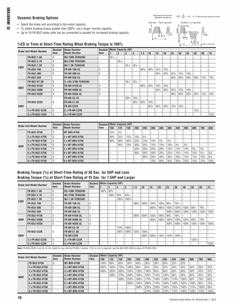
Dynamic Braking Options
%ED or Time at Short-Time Rating When Braking Torque is 100%
• Select the brake unit according to the motor capacity.• To obtain braking torque greater than 200%, use a larger inverter capacity.• Up to 10 FR-BU2 brake units can be connected in parallel for increased braking capacity.
Brake Unit Model Number Stocked Item
Brake Resistor Model Number
Stocked Item
Motor Capacity (HP)1 2 3 5 7.5 10 15 20 25 30 40 50 60 75
230V
FR-BU2-1.5K S BU-1500-TEIKOUKI - 30 s - - - - - - - - - - - - -FR-BU2-3.7K S BU-3700-TEIKOUKI - - 30 s - - - - - - - - - - - -FR-BU2-7.5K S BU-7.5K-TEIKOUKI - - - 30 s 30 s - - - - - - - - - -FR-BU2-15K S FR-BR-15K-UL S - - - - 80% 40% 15% 10% - - - - - -FR-BU2-30K S FR-BR-30K-UL S - - - - - - 65% 30% 25% 15% 10% - - -FR-BU2-55K - FR-BR-55K-UL - - - - - - - - - 90% 60% 30% 20% 15% 10%
460V
FR-BU2-H7.5K S 2 x BU-3700-TEIKOUKI - - - 30 s 30 s - - - - - - - - - -FR-BU2-H15K S FR-BR-H15K-UL S - - - - 80% 40% 15% 10% - - - - - -FR-BU2-H30K S FR-BR-H30K-UL S - - - - - - 65% 30% 25% 15% 10% - - -FR-BU2-H55K S FR-BR-H55K-UL S - - - - - - - - 90% 60% 30% 20% 15% 10%
600VFR-BU2-C22K S
FR-BR-C3.7K - - - 30% 10% - - - - - - - - - -FR-BR-C7.5K - - - - 40% 20% 10% - - - - - - - -FR-BR-C22K - - - - - - 85% 40% 20% 15% 10% - - - -
2 x FR-BU2-C22K S 2 x FR-BR-C22K - - - - - - - - - - - - 15% - -3 x FR-BU2-C22K S 3 x FR-BR-C22K - - - - - - - - - - - - - - 15%
Brake Unit Model Number Stocked Item
Brake Resistor Model Number
Stocked Item
Motor Capacity (HP)100 125 150 200 250 300 350 400 450 500 600 700 800
460V
FR-BU2-H75K S MT-BR5-H75K - 10% 5% - - - - - - - - - - -
2 x FR-BU2-H75K S 2 x MT-BR5-H75K - 40% 25% 15% 10% 5% - - - - - - - -3 x FR-BU2-H75K S 3 x MT-BR5-H75K - 90% 60% 40% 20% 14% 10% 5% 5% - - - - -4 x FR-BU2-H75K S 4 x MT-BR5-H75K - - 95% 70% 40% 25% 15% 13% 10% 5% 5% - - -5 x FR-BU2-H75K S 5 x MT-BR5-H75K - - - - 60% 40% 25% 20% 15% 12% 10% 5% 5% -6 x FR-BU2-H75K S 6 x MT-BR5-H75K - - - - 90% 55% 40% 25% 25% 15% 14% 10% 5% 5%7 x FR-BU2-H75K S 7 x MT-BR5-H75K - - - - - 80% 55% 40% 35% 20% 15% 13% 10% 5%8 x FR-BU2-H75K S 8 x MT-BR5-H75K - - - - - - 70% 50% 45% 30% 25% 15% 13% 10%
Braking Torque (%) at Short-Time Rating of 30 Sec. for 5HP and LessBraking Torque (%) at Short-Time Rating of 15 Sec. for 7.5HP and Larger
Brake Unit Model Number Stocked Item
Brake Resistor Model Number
Stocked Item
Motor Capacity (HP)1 2 3 5 7.5 10 15 20 25 30 40 50 60 75
230V
FR-BU2-1.5K S BU-1500-TEIKOUKI - 100% 50% - - - - - - - - - - - -FR-BU2-3.7K S BU-3700-TEIKOUKI - - 100% 50% 50% - - - - - - - - - -FR-BU2-7.5K S BU-7.5K-TEIKOUKI - - - 100% 100% - - - - - - - - - -
FR-BU2-15K S FR-BR-15K-UL S - - - - 280% 200% 120% 100% 80% 70% - - - -
FR-BU2-30K S FR-BR-30K-UL S - - - - - - 260% 180% 160% 130% 100% 80% 70% -FR-BU2-55K - FR-BR-55K-UL - - - - - - - - - 300% 250% 180% 150% 120% 100%
460VFR-BU2-H15K S FR-BR-H15K-UL S - - - - 280% 200% 120% 100% 80% 70% - - - -FR-BU2-H30K S FR-BR-H30K-UL S - - - - - - 260% 180% 160% 130% 100% 80% 70% -FR-BU2-H55K S FR-BR-H55K-UL S - - - - - - - - 300% 250% 180% 150% 120% 100%
600VFR-BU2-C22K S
FR-BR-C3.7K - - - 170% 100% - - - - - - - - - -FR-BR-C7.5K - - - 340% 200% 130% 100% - - - - - - - -FR-BR-C22K - - - - - - 300% 200% 145% 120% 100% - - - -
2 x FR-BU2-C22K S 2 x FR-BR-C22K - - - - - - - - - - - - 120% - -3 x FR-BU2-C22K S 3 x FR-BR-C22K - - - - - - - - - - - - - - 120%
Brake Unit Model Number Stocked Item
Brake Resistor Model Number
Stocked Item
Motor Capacity (HP)100 125 150 200 250 300 350 400 450 500 600 700 800
460V
FR-BU2-H75K S MT-BR5-H75K - 100% 80% 65% 50% 40% 30% 28% 26% 22% 20% - - -2 x FR-BU2-H75K - 2 x MT-BR5-H75K - 200% 165% 135% 100% 80% 65% 55% 53% 44% 40% 33% 28% 25%3 x FR-BU2-H75K - 3 x MT-BR5-H75K - 300% 250% 200% 150% 120% 100% 85% 80% 65% 60% 50% 43% 37%4 x FR-BU2-H75K - 4 x MT-BR5-H75K - - 300% 270% 200% 160% 135% 115% 105% 85% 80% 65% 55% 50%5 x FR-BU2-H75K - 5 x MT-BR5-H75K - - - 300% 250% 200% 170% 140% 130% 110% 100% 83% 70% 62%6 x FR-BU2-H75K - 6 x MT-BR5-H75K - - - - 300% 240% 200% 170% 160% 130% 120% 100% 85% 75%7 x FR-BU2-H75K - 7 x MT-BR5-H75K - - - - - 280% 235% 200% 185% 155% 140% 115% 100% 85%8 x FR-BU2-H75K - 8 x MT-BR5-H75K - - - - - - 270% 230% 210% 175% 160% 130% 110% 100%
Note: FR-BU2-C22K is not UL or cUL listed for use with the FR-BR-C resistor. If UL or cUL is required, use the ASC-RES-C22K in place of FR-BR-C22K.
Mitsubishi Electric Automation | Inverters 11Selection Guide Edition 19 • Revised April 1, 2019
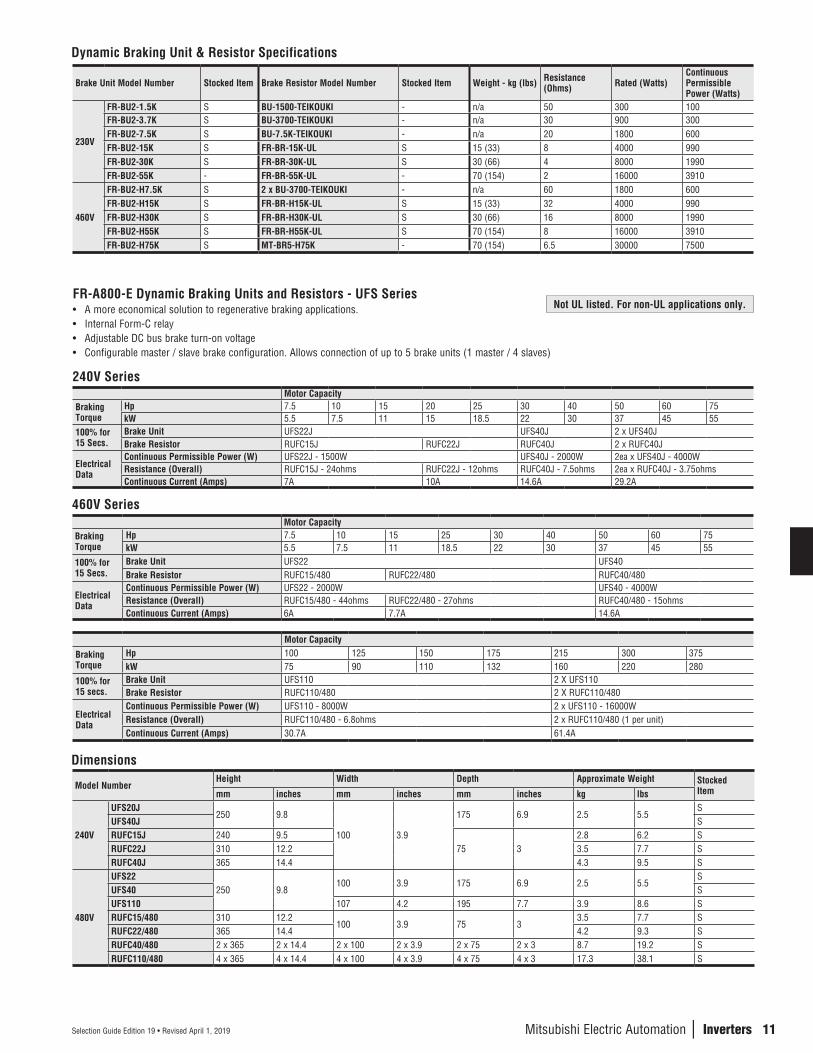
FR-A800-E Dynamic Braking Units and Resistors - UFS Series• A more economical solution to regenerative braking applications.• Internal Form-C relay• Adjustable DC bus brake turn-on voltage• Configurable master / slave brake configuration. Allows connection of up to 5 brake units (1 master / 4 slaves)
240V SeriesMotor Capacity
Braking Torque
Hp 7.5 10 15 20 25 30 40 50 60 75kW 5.5 7.5 11 15 18.5 22 30 37 45 55
100% for 15 Secs.
Brake Unit UFS22J UFS40J 2 x UFS40JBrake Resistor RUFC15J RUFC22J RUFC40J 2 x RUFC40J
Electrical Data
Continuous Permissible Power (W) UFS22J - 1500W UFS40J - 2000W 2ea x UFS40J - 4000WResistance (Overall) RUFC15J - 24ohms RUFC22J - 12ohms RUFC40J - 7.5ohms 2ea x RUFC40J - 3.75ohmsContinuous Current (Amps) 7A 10A 14.6A 29.2A
Dynamic Braking Unit & Resistor Specifications
Brake Unit Model Number Stocked Item Brake Resistor Model Number Stocked Item Weight - kg (lbs) Resistance (Ohms) Rated (Watts)
Continuous Permissible Power (Watts)
230V
FR-BU2-1.5K S BU-1500-TEIKOUKI - n/a 50 300 100FR-BU2-3.7K S BU-3700-TEIKOUKI - n/a 30 900 300FR-BU2-7.5K S BU-7.5K-TEIKOUKI - n/a 20 1800 600FR-BU2-15K S FR-BR-15K-UL S 15 (33) 8 4000 990FR-BU2-30K S FR-BR-30K-UL S 30 (66) 4 8000 1990FR-BU2-55K - FR-BR-55K-UL - 70 (154) 2 16000 3910
460V
FR-BU2-H7.5K S 2 x BU-3700-TEIKOUKI - n/a 60 1800 600FR-BU2-H15K S FR-BR-H15K-UL S 15 (33) 32 4000 990FR-BU2-H30K S FR-BR-H30K-UL S 30 (66) 16 8000 1990FR-BU2-H55K S FR-BR-H55K-UL S 70 (154) 8 16000 3910FR-BU2-H75K S MT-BR5-H75K - 70 (154) 6.5 30000 7500
460V SeriesMotor Capacity
Braking Torque
Hp 7.5 10 15 25 30 40 50 60 75kW 5.5 7.5 11 18.5 22 30 37 45 55
100% for 15 Secs.
Brake Unit UFS22 UFS40Brake Resistor RUFC15/480 RUFC22/480 RUFC40/480
Electrical Data
Continuous Permissible Power (W) UFS22 - 2000W UFS40 - 4000WResistance (Overall) RUFC15/480 - 44ohms RUFC22/480 - 27ohms RUFC40/480 - 15ohmsContinuous Current (Amps) 6A 7.7A 14.6A
Motor Capacity
Braking Torque
Hp 100 125 150 175 215 300 375kW 75 90 110 132 160 220 280
100% for 15 secs.
Brake Unit UFS110 2 X UFS110Brake Resistor RUFC110/480 2 X RUFC110/480
Electrical Data
Continuous Permissible Power (W) UFS110 - 8000W 2 x UFS110 - 16000WResistance (Overall) RUFC110/480 - 6.8ohms 2 x RUFC110/480 (1 per unit)Continuous Current (Amps) 30.7A 61.4A
Dimensions
Model NumberHeight Width Depth Approximate Weight Stocked
Itemmm inches mm inches mm inches kg lbs
240V
UFS20J250 9.8
100 3.9
175 6.9 2.5 5.5S
UFS40J SRUFC15J 240 9.5
75 32.8 6.2 S
RUFC22J 310 12.2 3.5 7.7 SRUFC40J 365 14.4 4.3 9.5 S
480V
UFS22250 9.8
100 3.9 175 6.9 2.5 5.5S
UFS40 SUFS110 107 4.2 195 7.7 3.9 8.6 SRUFC15/480 310 12.2
100 3.9 75 33.5 7.7 S
RUFC22/480 365 14.4 4.2 9.3 SRUFC40/480 2 x 365 2 x 14.4 2 x 100 2 x 3.9 2 x 75 2 x 3 8.7 19.2 SRUFC110/480 4 x 365 4 x 14.4 4 x 100 4 x 3.9 4 x 75 4 x 3 17.3 38.1 S
Not UL listed. For non-UL applications only.

12
n I
NVER
TERS
Selection Guide Edition 19 • Revised April 1, 2019
FR-A800-E Options and Accessories
External Heatsink AttachmentDrive Model F/A820 Drive Model F/A840 Model Number Stocked Item00105, 00167, 00250 00023, 00038, 00052, 00083, 00126 FR-A8CN01 S00340, 00490 00170, 00250 FR-A8CN02 S00630 00310, 00380 FR-A8CN03 S00770, 00930, 01250 00470, 00620 FR-A8CN04 S01540 00770 FR-A8CN05 S01870, 02330 00930, 01160, 01800 FR-A8CN06 S03160 - FR-A8CN07 S03800, 04750 03250, 03610 FR-A8CN08 S- 02160, 02600 FR-A8CN09 S
Model Number Description Comments Stocked ItemFR-A8AP Encoder Feedback Card Provides 1500:1 speed range and positioning control in Vector Mode S
FR-A8AL Encoder Feedback Card, Orient, Vector Position Control and Encoder Dividing Output
Multi function feedback option – includes 1500:1 speed range and positioning control in vector mode, Ideal for spindle orient and machine tool S
FR-A8TP Vector Control Terminal Block Enables encoder feedback on I/O terminal block instead of option card slot, combine with FR-A8AP for orient control S
FR-A8ERS-60 A/F800 Series RS485 Option Card SFR-A8AX 16 Bit Digital Input Card BCD or Binary input SFR-A8AY Digital Output / Extended Analog Output Card 2 extra 0-20 mA or 0-10V output signals SFR-A8AR Relay Output Card 3 extra independent type 'C' relays SFR-A8AZ High Res. Analog / Thermistor input Card -FR-A8AC A/F800 120V Control Option SFR-A8AN F/A800 4-20mA I/O Card SFR-A8APR Resolver Interface / Orientation Card -FR-A8APS Absolute Encoder Option EnDat 2.x Interface S
FR-A8NC CC-Link Communications Card A6CON-L5P / A6CON-TR11N connectors not included with Option card (Sold Separately) S
FR-A8ND DeviceNet Communications Card SFR-A8NP PROFIBUS DPV0 Communications Card SA8NDPV1 PROFIBUS DPV1 Communications Card SFR-A8NF FL-Net Communications Card SA8N-XLT Muli-protocol RS485 Communications Card (BACnet® MS/TP), Siemens FLN (P1), Metasys® N2 SFR-A8NS SSCNET III / F Communications Card -A8NEIP-2P EtherNET IP™ Communications Card SA8NPRT-2P PROFINET® Communications Card SFR-A8NCN ControlNet™ Communications Card SFR-A8NCE CC-Link® IE Communications Card SFR-A8NCA CanOpen Communication Card -FR-A8NL LonWorks Communication Card SA8NECT-2P EtherCAT® Communications Card SA8NETH-2P Multi-protocol EtherNET Communications Card EtherNET IP, MODBUS TCP/IP, Profinet, BACnet IP SFR-LU08 Liquid Crystal Operation Panel Mount on VFD or panel SFR-PU07, FR-PU07-01 Parameter Unit Mount on panel only. FR-PU07-1 is for HVAC SFR-PU07BB-L Parameter Unit with Battery Back-up Hand held. Can program unpowered drives SFR-CB20_ (_ = 1, 3 or 5) Parameter Unit Connection Cable 1, 3 or 5 meter lengths SFR-ADP Keypad Adaptor Unit Connect FR-DU08 or FR-LU08 to FR-CB2 SFR-A8TAT Control Terminal Block Adaptor Use A500 or A700 terminal block with A800 SFR-A8TR Screw Terminal Block Option Screw Terminal Block Option SFR-ABR High Duty Brake Resistor Use with drives 30HP or below (ND rating) SFR-BR Brake Resistor Use with drives 75HP or below (ND rating) SMT-BR5 Brake Resistor Use with drives 100HP or below (ND rating) SFR-CV, FR-CVL Regenerative Controller Use with drives 75HP or below (ND rating) SMT-RC Regenerative Controller Use with drives 100HP or ABOVE (ND rating) -FR-HC2 Zero Harmonic Controller Available for all sizes SFR-HEL, FR-HEL-H, FR-HEL-C DC Link Choke Use in accordance with selection guide SFR-CONFIGURATOR2 Software Setup Utility for FR-800 Series S
NEMA 1 Conduit Mounting Kits for A and FR-F800 Series DrivesKits have provision for DC link choke installation (Drives in frame sizes A to F do not require a separate kit)
Model Number A/F820 A/F840 Frame SizeAF8FN-G 01540 00770 G
AF8FN-H01870 00930
H02330 01160- 01800
AF8FN-J- 02160
J- 02600
AF8FN-K 03160 - K
AF8FN-L03800 03250
L04750 03610
AF8FN-M- 04320
M- 04810
AF8FN-N- 05470
N- 06100- 06830
13
n I
NVER
TERS
Selection Guide Edition 19 • Revised April 1, 2019
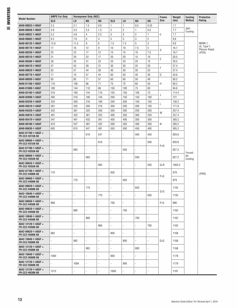
Model NumberAMPS For Duty Horsepower Duty (NEC) Frame
SizeWeight (lbs)
Cooling Method
Protective RatingSLD LD ND HD SLD LD ND HD
A840-00023-1-N6GF 2.3 2.1 1.5 0.8 1 1 0.5 0.25
C
7.7Self-Cooling
NEMA 1,UL Type-1,Plenum Rated(IP20)
A840-00038-1-N6GF 3.8 3.5 2.5 1.5 2 2 1 0.5 7.7
A840-00052-1-N6GF 5.2 4.8 4 2.5 3 3 2 1 7.7
A840-00083-1-N6GF 8.3 7.6 6 4 5 5 3 2 8.8
Forced-AirCooling
A840-00126-1-N6GF 12.6 11.5 9 6 7.5 7.5 5 3 8.8
A840-00170-1-N6GF 17 16 12 9 10 10 7.5 5D
16.7
A840-00250-1-N6GF 25 23 17 12 15 15 10 7.5 16.7
A840-00310-1-N6GF 31 29 23 17 20 20 15 10E
20.5
A840-00380-1-N6GF 38 35 31 23 25 25 20 15 20.5
A840-00470-1-N6GF 47 43 38 31 30 30 25 20F
37.4
A840-00620-1-N6GF 62 57 44 38 40 40 30 25 37.4
A840-00770-1-60GF 77 70 57 44 60 50 40 30 G 50.6
(IP00)
A840-00930-1-60GF 93 85 71 57 60 60 50 40
H
90.2
A840-01160-1-60GF 116 106 86 71 75 75 60 50 90.2
A840-01800-1-60GF 180 144 110 86 150 100 75 60 94.6
A840-02160-1-U6GF 216 180 144 110 150 150 100 75J
114.4
A840-02600-1-U6GF 260 216 180 144 200 150 150 100 121
A840-03250-1-U6GF 325 260 216 180 250 200 150 150L
156.2
A840-03610-1-U6GF 361 325 260 216 300 250 200 150 171.6
A840-04320-1-U6GF 432 361 325 260 350 300 250 200M
257.4
A840-04810-1-U6GF 481 432 361 325 400 350 300 250 257.4
A840-05470-1-U6GF 547 481 432 361 450 400 350 300
N
365.2
A840-06100-1-U6GF 610 547 481 432 500 450 400 350 365.2
A840-06830-1-U6GF 683 610 547 481 550 500 450 400 365.2
A842-07700-1-U6GF + FR-CC2-H315K-60 - - 610 547 - - 500 450
P+R
820.6
A842-08660-1-U6GF + FR-CC2-H315K-60 - - - 610 - - - 500 820.6
A842-07700-1-U6GF + FR-CC2-H355K-60 - 683 - - - 550 - - 827.2
A842-08660-1-U6GF + FR-CC2-H355K-60 - - 683 - - - 550 - 827.2
A842-09620-1-U6GF + FR-CC2-H355K-60 - - - 683 - - - 550 Q+R 1003.2
A842-07700-1-U6GF + FR-CC2-H400K-60 770 - - - 650 - - -
P+S979
A842-08660-1-U6GF + FR-CC2-H400K-60 - 770 - - - 650 - - 979
A842-09620-1-U6GF + FR-CC2-H400K-60 - - 770 - - - 650 -
Q+S1155
A842-10940-1-U6GF + FR-CC2-H400K-60 - - - 770 - - - 650 1155
A842-08660-1-U6GF + FR-CC2-H450K-60 866 - - - 700 - - - P+S 986
A842-09620-1-U6GF + FR-CC2-H450K-60 - 866 - - - 700 - -
Q+S
1162
A842-10940-1-U6GF + FR-CC2-H450K-60 - - 866 - - - 700 - 1162
A842-12120-1-U6GF + FR-CC2-H450K-60 - - - 866 - - - 700 1162
A842-09620-1-U6GF + FR-CC2-H500K-60 962 - - - 800 - - - 1168
A842-10940-1-U6GF + FR-CC2-H500K-60 - 962 - - - 800 - - 1168
A842-12120-1-U6GF + FR-CC2-H500K-60 - - 962 - - - 800 - 1168
A842-10940-1-U6GF + FR-CC2-H560K-60 1094 - - - 900 - - - 1179
A842-12120-1-U6GF + FR-CC2-H560K-60 - 1094 - - - 900 - - 1179
A842-12120-1-U6GF + FR-CC2-H630K-60 1212 - - - 1000 - - - 1181

Mitsubishi Electric Automation | Inverters 14Selection Guide Edition 19 • Revised April 1, 2019
FR-A800 Plus ProgramFR-A800 Plus takes the outstanding performance and functionality of the regular FR-A800 VFD and combines it with special firmware to make a drive dedicated to specific industry sectors. For main specifications please refer to the standard FR-A800 section. Note that FR-A800 Plus is not currently available as a 600V version.
FR-A800CRN Crane Control version of FR-A800 includes:• Anti-Sway Control – Eliminates swinging
loads caused by speed changes during loadhandling, ensuring smoother operation andreduced ‘tact’ time
• Shortest Time Start-up Feature – Adapts tochanging load masses
• Dedicated Sequencing System – Interfacewith mechanical brakes during raising andlowering
• Falling Load Detection – Detectsunexpected load dropping
• Hoist and Travel Control – Coordinateslifting and traveling operations
FR-A800R2R Roll-to-Roll version of FR-A800 for wind/unwind and tension control applications includes:• Diameter Calculation Capability – Detects
initial roll diameter and calculates diameterchange during operation
• Dedicated PI Control System – Ensuressmooth tension control
• Process Compensation – Adjusts for loadinertia during speed changes
• Break Detection – Detects a breakage inmaterial between rolls
• Taper Function – Allows a gradual changein tension to avoid wrinkling or stretching offilms as the load diameter changes
• SND Rating – An extra duty rating whichallows higher operating current than NDrating while still allowing 150% motorcurrent overload for 60 seconds (short timeoverload is removed)
Part Number SystemThe basic part numbering system is the same as for the standard drives but includes a suffix at the end.
A 1 - 2 -1- 3
Symbol Voltage Class820 240V Class840 480V Class842 480V Class
1 Max Load CapacitySymbol
See FR-A800 section for available capacities.
2 CapacitySymbol Control
N6CRN Class Crane Control
60CRN Class Crane ControlU6CRN Class Crane Control*N6R2R Class Roll-toRoll Control60R2R Class Roll-toRoll ControlU6R2R Class Roll-toRoll Control*
3 Control
*Inverter stage only. Use in conjunction with FR-CC2.
15
n I
NVER
TERS
Selection Guide Edition 19 • Revised April 1, 2019
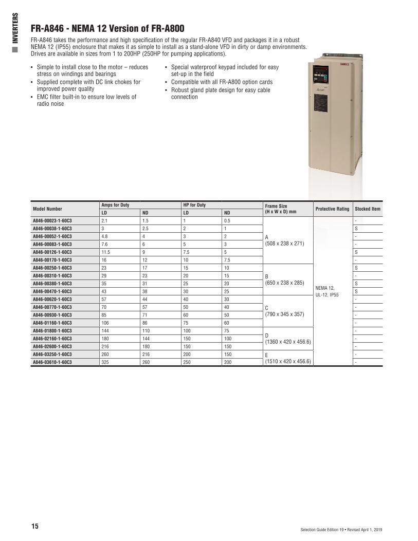
FR-A846 - NEMA 12 Version of FR-A800FR-A846 takes the performance and high specification of the regular FR-A840 VFD and packages it in a robust NEMA 12 (IP55) enclosure that makes it as simple to install as a stand-alone VFD in dirty or damp environments. Drives are available in sizes from 1 to 200HP (250HP for pumping applications).
• Simple to install close to the motor – reducesstress on windings and bearings
• Supplied complete with DC link chokes forimproved power quality
• EMC filter built-in to ensure low levels ofradio noise
• Special waterproof keypad included for easyset-up in the field
• Compatible with all FR-A800 option cards• Robust gland plate design for easy cable
connection
Model NumberAmps for Duty HP for Duty Frame Size
(H x W x D) mm Protective Rating Stocked ItemLD ND LD ND
A846-00023-1-60C3 2.1 1.5 1 0.5
A(508 x 238 x 271)
NEMA 12, UL-12, IP55
-
A846-00038-1-60C3 3 2.5 2 1 S
A846-00052-1-60C3 4.8 4 3 2 -
A846-00083-1-60C3 7.6 6 5 3 -
A846-00126-1-60C3 11.5 9 7.5 5 S
A846-00170-1-60C3 16 12 10 7.5 -
A846-00250-1-60C3 23 17 15 10
B(650 x 238 x 285)
S
A846-00310-1-60C3 29 23 20 15 -
A846-00380-1-60C3 35 31 25 20 S
A846-00470-1-60C3 43 38 30 25 S
A846-00620-1-60C3 57 44 40 30
C(790 x 345 x 357)
-
A846-00770-1-60C3 70 57 50 40 -
A846-00930-1-60C3 85 71 60 50 -
A846-01160-1-60C3 106 86 75 60 -
A846-01800-1-60C3 144 110 100 75D(1360 x 420 x 456.6)
-
A846-02160-1-60C3 180 144 150 100 -
A846-02600-1-60C3 216 180 150 150 -
A846-03250-1-60C3 260 216 200 150 E(1510 x 420 x 456.6)
-
A846-03610-1-60C3 325 260 250 200 -


