FPS-K10x LTE UL User Manual - Rohde & Schwarz LTE measurements with their corresponding remote...
221
R&S ® FPS-K10x (LTE Uplink) LTE Uplink Measurement Application User Manual User Manual 1176.8816.02 ─ 07 (;Úæ@2) Test & Measurement
-
Upload
vuongtuong -
Category
Documents
-
view
249 -
download
3
Transcript of FPS-K10x LTE UL User Manual - Rohde & Schwarz LTE measurements with their corresponding remote...
R&S®FPS-K10x (LTE Uplink)LTE Uplink Measurement ApplicationUser Manual
User
Man
ual
1176.8816.02 ─ 07(;Úæ@2)
Test
& Me
asur
emen
t
This manual applies to the following R&S®FPS models with firmware version 1.50 and higher:
● R&S®FPS4 (1319.2008K04)
● R&S®FPS7 (1319.2008K07)
● R&S®FPS13 (1319.2008K13)
● R&S®FPS30 (1319.2008K30)
● R&S®FPS40 (1319.2008K40)
The following firmware options are described:● R&S FPS-K101 (LTE FDD UL) (1321.4340.02)
● R&S FPS-K103 (LTE UL MIMO) (1321.4356.02)
● R&S FPS-K105 (LTE TDD UL) (1321.4362.02)
© 2017 Rohde & Schwarz GmbH & Co. KGMühldorfstr. 15, 81671 München, GermanyPhone: +49 89 41 29 - 0Fax: +49 89 41 29 12 164Email: [email protected]: www.rohde-schwarz.comSubject to change – Data without tolerance limits is not binding.R&S® is a registered trademark of Rohde & Schwarz GmbH & Co. KG.Trade names are trademarks of their owners.
Throughout this manual, products from Rohde & Schwarz are indicated without the ® symbol , e.g. R&S®FPS is indicated asR&S FPS.
ContentsR&S®FPS-K10x (LTE Uplink)
3User Manual 1176.8816.02 ─ 07
Contents1 Preface.................................................................................................... 5
1.1 About this Manual......................................................................................................... 5
1.2 Typographical Conventions.........................................................................................5
2 Welcome to the LTE Measurement Application..................................72.1 Overview of the LTE Applications............................................................................... 7
2.2 Installation..................................................................................................................... 9
2.3 Starting the LTE Measurement Application................................................................9
2.4 Understanding the Display Information....................................................................10
3 Measurements and Result Displays...................................................123.1 Selecting Measurements............................................................................................ 12
3.2 Selecting Result Displays.......................................................................................... 13
3.3 Performing Measurements.........................................................................................14
3.4 Selecting the Operating Mode................................................................................... 14
3.5 I/Q Measurements....................................................................................................... 15
3.6 Time Alignment Error Measurements....................................................................... 28
3.7 Frequency Sweep Measurements............................................................................. 30
3.8 3GPP Test Scenarios.................................................................................................. 36
4 Measurement Basics........................................................................... 384.1 Symbols and Variables...............................................................................................38
4.2 Overview...................................................................................................................... 39
4.3 The LTE Uplink Analysis Measurement Application............................................... 39
4.4 Performing Time Alignment Measurements.............................................................43
4.5 SRS EVM Calculation..................................................................................................44
5 Configuration........................................................................................465.1 Configuration Overview..............................................................................................46
5.2 Configuring I/Q Measurements..................................................................................48
5.3 Configuring Time Alignment Error Measurements..................................................86
5.4 Configuring Frequency Sweep Measurements........................................................ 87
6 Analysis................................................................................................ 906.1 Configuring Tables / Numerical Results................................................................... 90
ContentsR&S®FPS-K10x (LTE Uplink)
4User Manual 1176.8816.02 ─ 07
6.2 Exporting Measurement Results............................................................................... 90
6.3 Analyzing I/Q Measurements..................................................................................... 91
6.4 Analyzing Frequency Sweep Measurements........................................................... 97
7 Remote Control.................................................................................... 987.1 Common Suffixes........................................................................................................98
7.2 Introduction................................................................................................................. 99
7.3 Remote Commands to Select the LTE Application................................................104
7.4 General Window Commands................................................................................... 107
7.5 Working with Windows in the Display.................................................................... 108
7.6 Performing Measurements.......................................................................................116
7.7 Remote Commands to Read Trace Data.................................................................121
7.8 Remote Commands to Read Numeric Results.......................................................133
7.9 Remote Commands to Read Limit Check Results.................................................147
7.10 Remote Commands to Configure the Application................................................. 157
7.11 Analysis..................................................................................................................... 205
List of Commands..............................................................................213
Index....................................................................................................219
PrefaceR&S®FPS-K10x (LTE Uplink)
5User Manual 1176.8816.02 ─ 07
1 Preface
1.1 About this Manual
This LTE User Manual provides all the information specific to the application. Allgeneral instrument functions and settings common to all applications and operatingmodes are described in the main R&S FPS User Manual.
The main focus in this manual is on the LTE measurement results and the tasksrequired to obtain them. The following topics are included:
● Welcome to the LTE applicationIntroduction to and getting familiar with the application
● Measurements and result displaysDetails on supported LTE measurements and their result types
● Measurement basicsBackground information on basic terms and principles in the context of LTE mea-surements
● Configuration and analysisA concise description of all functions and settings available to configure and ana-lyze LTE measurements with their corresponding remote control command
● Optimizing and troubleshooting the measurementHints and tips on how to handle errors and optimize the test setup
● Remote commands for LTE measurementsRemote commands required to configure and perform LTE measurements in aremote environment, sorted by tasks(Commands required to set up the environment or to perform common tasks on theinstrument are provided in the main R&S FPS User Manual)
● List of remote commandsAlpahabetical list of all remote commands described in the manual
● Index
1.2 Typographical Conventions
The following text markers are used throughout this documentation:
Convention Description
"Graphical user interface ele-ments"
All names of graphical user interface elements on the screen, such asdialog boxes, menus, options, buttons, and softkeys are enclosed byquotation marks.
KEYS Key names are written in capital letters.
File names, commands,program code
File names, commands, coding samples and screen output are distin-guished by their font.
Typographical Conventions
PrefaceR&S®FPS-K10x (LTE Uplink)
6User Manual 1176.8816.02 ─ 07
Convention Description
Input Input to be entered by the user is displayed in italics.
Links Links that you can click are displayed in blue font.
"References" References to other parts of the documentation are enclosed by quota-tion marks.
Typographical Conventions
Welcome to the LTE Measurement ApplicationR&S®FPS-K10x (LTE Uplink)
7User Manual 1176.8816.02 ─ 07
2 Welcome to the LTE Measurement Applica-tionThe R&S FPS-K101, -K103 and -K105 are firmware applications that add functionalityto measure LTE signals according to the 3GPP standard to the R&S FPS.
This user manual contains a description of the functionality that the application pro-vides, including remote control operation. Functions that are not discussed in this man-ual are the same as in the Spectrum application and are described in the R&S FPSUser Manual. The latest versions of the manuals are available for download at theproduct homepage.
http://www2.rohde-schwarz.com/product/fps.html.
● Overview of the LTE Applications............................................................................. 7● Installation.................................................................................................................9● Starting the LTE Measurement Application...............................................................9● Understanding the Display Information...................................................................10
2.1 Overview of the LTE Applications
You can equip the R&S FPS with one or more LTE applications. Each of the applica-tions provides functionality for specific measurement tasks.
R&S FPS-K100
The R&S FPS-K100 is designed to measure LTE FDD signals on the downlink.
The application has the following features:● Basic signal characteristics (like frequency, channel bandwidth or cyclic prefix).● Demodulation and configuration of the PDSCH transmitted over a single antenna
and without precoding functionality.● Characteristics of the Synchronization and Reference signals.● Consideration of various control channels in the measurement (for example the
PBCH or the PPDCH).● Analysis of individual antennas in a MIMO setup.● Tools to refine and filter the measurement results.● Various result displays that show the measured signal characteristics in a diagram
or a numeric result table.● Available measurements: EVM, ACLR and SEM.
R&S FPS-K101
The R&S FPS-K101 is designed to measure LTE FDD signals on the uplink.
The application has the following features:● Basic signal characteristics (like frequency, channel bandwidth or cyclic prefix).
Overview of the LTE Applications
Welcome to the LTE Measurement ApplicationR&S®FPS-K10x (LTE Uplink)
8User Manual 1176.8816.02 ─ 07
● Demodulation and configuration of the subframes transmitted over a singleantenna.
● Characteristics of the Demodulation and Sounding Reference signals.● Consideration of the PUSCH, PUCCH and PRACH channels.● Analysis of individual antennas in a MIMO setup.● Tools to refine and filter the measurement results.● Various result displays that show the measured signal characteristics in a diagram
or a numeric result table.● Available measurements: EVM, ACLR and SEM.
R&S FPS-K102
The R&S FPS-K102 is designed to measure LTE Advanced systems and MIMO sys-tems on the downlink.
Note that this application only works in combination with either R&S FPS-K100 or -K104.
The application has the following features:● Support of 1024QAM modulation.● Simultaneous (or consecutive) capture and subsequent analysis of the data
streams of several antennas.● Control of several analyzers required for MIMO measurements.● Consideration of the Precoding schemes defined in the 3GPP standard.● Support of Carrier Aggregation.● Measurements on Multimedia Broadcast Single Frequency Networks (MBSFNs).● Additional measurements: Time Alignment Error, Multi-Carrier ACLR, Cumulative
ACLR and Multi-SEM.
R&S FPS-K103
The R&S FPS-K103 is designed to measure LTE Advanced systems on the uplink.
Note that this application only works in combination with either R&S FPS-K101 or -K105.
The application has the following features:● Support of 256QAM modulation.● Simultaneous (or consecutive) capture and subsequent analysis of the data
streams of several antennas.● Control of several analyzers required for MIMO measurements.● Consideration of the enhanced PUSCH and PUCCH characteristics.● Support of Carrier Aggregation.● Additional measurements: Time Alignment Error, Multi-Carrier ACLR and Multi
SEM.
Overview of the LTE Applications
Welcome to the LTE Measurement ApplicationR&S®FPS-K10x (LTE Uplink)
9User Manual 1176.8816.02 ─ 07
R&S FPS-K104
The R&S FPS-K104 is designed to measure LTE TDD signals on the downlink.
The features are basically the same as in the R&S FPS-K100 with additional featuresthat allow you to configure TDD subframes. It also provides tools to measure theOn/Off Power.
R&S FPS-K105
The R&S FPS-K105 is designed to measure LTE TDD signals on the uplink.
The features are basically the same as in the R&S FPS-K101 with additional featuresthat allow you to configure TDD subframes.
2.2 Installation
Find detailed installing instructions in the Getting Started or the release notes of theR&S FPS.
2.3 Starting the LTE Measurement Application
The LTE measurement application adds a new application to the R&S FPS.
Manual operation via an external monitor and mouseAlthough the R&S FPS does not have a built-in display, it is possible to operate it inter-actively in manual mode using a graphical user interface with an external monitor anda mouse connected.It is recommended that you use the manual mode initially to get familiar with the instru-ment and its functions before using it in pure remote mode. Thus, this documentdescribes in detail how to operate the instrument manually using an external monitorand mouse. The remote commands are described in the second part of the document.For details on manual operation, see the R&S FPS Getting Started manual.
To activate the application
1. Press the MODE key on the front panel of the R&S FPS.
A dialog box opens that contains all operating modes and applications currentlyavailable on your R&S FPS.
2. Select the "LTE" item.
Starting the LTE Measurement Application
Welcome to the LTE Measurement ApplicationR&S®FPS-K10x (LTE Uplink)
10User Manual 1176.8816.02 ─ 07
The R&S FPS opens a new measurement channel for the LTE measurement appli-cation.
The measurement is started immediately with the default settings. It can be configuredin the "Overview" dialog box, which is displayed when you select the "Overview" soft-key from any menu.
For more information, see Chapter 5, "Configuration", on page 46.
2.4 Understanding the Display Information
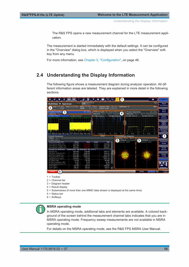
The following figure shows a measurement diagram during analyzer operation. All dif-ferent information areas are labeled. They are explained in more detail in the followingsections.
1 = Toolbar2 = Channel bar3 = Diagram header4 = Result display5 = Subwindows (if more than one MIMO data stream is displayed at the same time)5 = Status bar6 = Softkeys
MSRA operating modeIn MSRA operating mode, additional tabs and elements are available. A colored back-ground of the screen behind the measurement channel tabs indicates that you are inMSRA operating mode. Frequency sweep measurements are not available in MSRAoperating mode.For details on the MSRA operating mode, see the R&S FPS MSRA User Manual.
Understanding the Display Information

Welcome to the LTE Measurement ApplicationR&S®FPS-K10x (LTE Uplink)
11User Manual 1176.8816.02 ─ 07
Channel bar information
In the LTE measurement application, the R&S FPS shows the following settings:
Table 2-1: Information displayed in the channel bar in the LTE measurement application
Ref Level Reference level
Att Mechanical and electronic RF attenuation
Freq Frequency
Mode LTE standard
MIMO Number of Tx and Rx antennas in the measurement setup
Capture Time Signal length that has been captured
Frame Count Number of frames that have been captured
Selected Slot Slot considered in the signal analysis
Selected Subframe Subframe considered in the signal analysis
In addition, the channel bar also displays information on instrument settings that affectthe measurement results even though this is not immediately apparent from the displayof the measured values (for example transducer or trigger settings). This information isdisplayed only when applicable for the current measurement. For details, see theR&S FPS Getting Started manual.
Window title bar information
The information in the window title bar depends on the result display.
The "Constellation Diagram", for example, shows the number of points that have beenmeasured.
Status bar information
Global instrument settings, the instrument status and any irregularities are indicated inthe status bar beneath the diagram. Furthermore, the progress of the current operationis displayed in the status bar.
Regarding the synchronization state, the application shows the following labels.● Sync OK
The synchronization was successful. The status bar is green.● Sync Failed
The synchronization was not successful. The status bar is red.There can be three different synchronization errors.– Sync Failed (Cyclic Prefix): The cyclic prefix correlation failed.– Sync Failed (P-SYNC): The P-SYNC correlation failed.– Sync Failed (S-SYNC): The S-SYNC correlation failed.
Understanding the Display Information
Measurements and Result DisplaysR&S®FPS-K10x (LTE Uplink)
12User Manual 1176.8816.02 ─ 07
3 Measurements and Result DisplaysThe LTE measurement application measures and analyzes various aspects of an LTEsignal.
It features several measurements and result displays. Measurements represent differ-ent ways of processing the captured data during the digital signal processing. Resultdisplays are different representations of the measurement results. They may be dia-grams that show the results as a graph or tables that show the results as numbers.
Remote command:
Measurement selection: CONFigure[:LTE]:MEASurement on page 158
Result display selection: LAYout:ADD[:WINDow]? on page 109
● Selecting Measurements.........................................................................................12● Selecting Result Displays........................................................................................13● Performing Measurements......................................................................................14● Selecting the Operating Mode.................................................................................14● I/Q Measurements...................................................................................................15● Time Alignment Error Measurements..................................................................... 28● Frequency Sweep Measurements.......................................................................... 30● 3GPP Test Scenarios..............................................................................................36
3.1 Selecting Measurements
► Press the MEAS key.
The application opens a dialog box that contains several buttons.Each button represents a set of result displays that thematically belong togetherand that have a particular display configuration. If these predefined display configu-rations do not suit your requirements, you can add or remove result displays asyou like. For more information about selecting result displays, see Chapter 3.2,"Selecting Result Displays", on page 13.
Depending on the button you select, the application changes the way the R&S FPScaptures and processes the raw signal data.
● When you select "EVM", the application processes the I/Q data of the signal. Formore information on available I/Q result displays, see Chapter 3.5, "I/Q Measure-ments", on page 15.When you select one of the result displays available for I/Q measurements, youcan combine the result displays available for I/Q measurements in any way.
● When you select "Channel Power ACLR" or "Spectrum Emission Mask", the appli-cation performs a frequency sweep. For more information, see Chapter 3.7, "Fre-quency Sweep Measurements", on page 30.
Selecting Measurements
Measurements and Result DisplaysR&S®FPS-K10x (LTE Uplink)
13User Manual 1176.8816.02 ─ 07
When you select one of the frequency sweep measurements, you can combine theresult displays available for the frequency sweep measurements in any way. Notethat you cannot display the ACLR and SEM at the same time.
Remote command:
CONFigure[:LTE]:MEASurement on page 158
3.2 Selecting Result Displays
► Select the icon in the toolbar or press the "Display Config" softkey in the "Mea-surement" menu.
The application enters the SmartGrid configuration mode.For more information on the SmartGrid functionality, see the R&S FPS GettingStarted.
In the default state of the application, it shows several conventional result displays.● Capture Buffer● EVM vs Carrier● Power Spectrum● Result Summary● Constellation Diagram
From that predefined state, add and remove result displays as you like from the evalu-ation bar.
Remote command:
LAYout:ADD[:WINDow]? on page 109
Note that you can customize the contents of some numerical result displays. For moreinformation, see Chapter 6.1, "Configuring Tables / Numerical Results", on page 90.
MIMO measurementsWhen you capture more than one data stream, each result display is made up out ofseveral tabs.The first tab shows the results for all data streams. The other tabs show the results foreach individual data stream. By default, the tabs are coupled to one another - if youselect a particular data stream in one display, the application also selects this datastream in the other result displays (see Subwindow Coupling).The number of tabs depends on the number of data streams.
Selecting Result Displays
Measurements and Result DisplaysR&S®FPS-K10x (LTE Uplink)
14User Manual 1176.8816.02 ─ 07
3.3 Performing Measurements
By default, the application measures the signal continuously. In "Continuous Sweep"mode, the R&S FPS captures and analyzes the data again and again.● For I/Q measurements, the amount of captured data depends on the capture time.● For frequency sweep measurement, the amount of captured data depends on the
sweep time.
In "Single Sweep" mode, the R&S FPS stops measuring after it has captured the dataonce. The amount of data again depends on the capture time.
You can also repeat a measurement based on the data that has already been capturedwith the "Refresh" function. Repeating a measurement with the same data can be use-ful, for example, if you want to apply different modulation settings to the same I/Q data.
For more information, see the documentation of the R&S FPS.
3.4 Selecting the Operating Mode
Access: MODE > "Multi-Standard Radio Analyzer Tab"
The LTE application is supported by the Multi Standard Radio Analyzer (MSRA).
The MSRA mode supports all I/Q measurements and result displays available with theLTE application, except the frequency sweep measurements (SEM and ACLR).
In MSRA operating mode, only the MSRA master actually captures data. The applica-tion receives an extract of the captured data for analysis, referred to as the applicationdata. The application data range is defined by the same settings used to define thesignal capture in "Signal and Spectrum Analyzer" mode. In addition, a capture offsetcan be defined, i.e. an offset from the start of the captured data to the start of theanalysis interval.
If a signal contains multiple data channels for multiple standards, separate applicationsare used to analyze each data channel. Thus, it is of interest to know which applicationis analyzing which data channel. The MSRA master display indicates the data coveredby each application by vertical blue lines labeled with the application name. The bluelines correspond to the channel bandwidth.
However, the individual result displays of the application need not analyze the com-plete data range. The data range that is actually analyzed by the individual result dis-play is referred to as the analysis interval.
The analysis interval is automatically determined according to the Capture Time youhave defined. The analysis interval cannot be edited directly in the LTE application, butis changed automatically when you change the evaluation range. The currently usedanalysis interval (in seconds, related to capture buffer start) is indicated in the windowheader for each result display.
Selecting the Operating Mode

Measurements and Result DisplaysR&S®FPS-K10x (LTE Uplink)
15User Manual 1176.8816.02 ─ 07
A frequent question when analyzing multi-standard signals is how each data channel iscorrelated (in time) to others. Thus, an analysis line has been introduced. The analysisline is a common time marker for all MSRA slave applications. It can be positioned inany MSRA slave application or the MSRA Master and is then adjusted in all other slaveapplications. Thus, you can easily analyze the results at a specific time in the measure-ment in all slave applications and determine correlations.
If the marked point in time is contained in the analysis interval of the slave application,the line is indicated in all time-based result displays, such as time, symbol, slot or bitdiagrams. By default, the analysis line is displayed, however, it can be hidden fromview manually. In all result displays, the "AL" label in the window title bar indicateswhether the analysis line lies within the analysis interval or not:
● orange "AL": the line lies within the interval● white "AL": the line lies within the interval, but is not displayed (hidden)● no "AL": the line lies outside the interval
For details on the MSRA operating mode, see the R&S FPS MSRA documentation.
3.5 I/Q Measurements
Access: MEAS > "EVM/Frequency Err/Power"
You can select the result displays from the evaluation bar and arrange them as you likewith the SmartGrid functionality.
Remote command:
Measurement selection: CONFigure[:LTE]:MEASurement on page 158
Result display selection: LAYout:ADD[:WINDow]? on page 109
Capture Buffer...............................................................................................................16EVM vs Carrier..............................................................................................................16EVM vs Symbol.............................................................................................................17EVM vs Subframe......................................................................................................... 18Power Spectrum............................................................................................................18Inband Emission............................................................................................................19Spectrum Flatness........................................................................................................ 19Spectrum Flatness SRS................................................................................................20Group Delay.................................................................................................................. 20Spectrum Flatness Difference.......................................................................................21Constellation Diagram...................................................................................................21CCDF............................................................................................................................ 21Allocation Summary...................................................................................................... 22Bit Stream..................................................................................................................... 23EVM vs Symbol x Carrier.............................................................................................. 24Power vs Symbol x Carrier............................................................................................24Result Summary............................................................................................................24Marker Table ................................................................................................................ 27
I/Q Measurements
Measurements and Result DisplaysR&S®FPS-K10x (LTE Uplink)
16User Manual 1176.8816.02 ─ 07
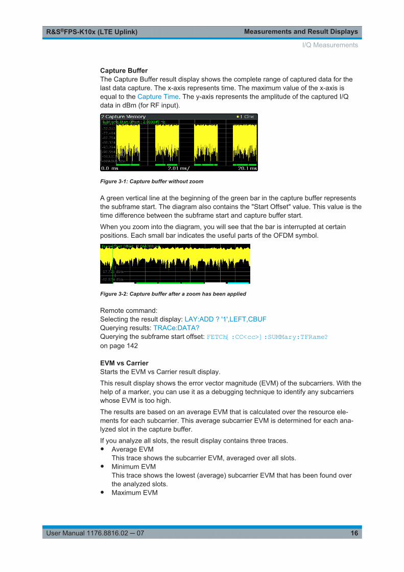
Capture BufferThe Capture Buffer result display shows the complete range of captured data for thelast data capture. The x-axis represents time. The maximum value of the x-axis isequal to the Capture Time. The y-axis represents the amplitude of the captured I/Qdata in dBm (for RF input).
Figure 3-1: Capture buffer without zoom
A green vertical line at the beginning of the green bar in the capture buffer representsthe subframe start. The diagram also contains the "Start Offset" value. This value is thetime difference between the subframe start and capture buffer start.
When you zoom into the diagram, you will see that the bar is interrupted at certainpositions. Each small bar indicates the useful parts of the OFDM symbol.
Figure 3-2: Capture buffer after a zoom has been applied
Remote command: Selecting the result display: LAY:ADD ? '1',LEFT,CBUFQuerying results: TRACe:DATA?Querying the subframe start offset: FETCh[:CC<cc>]:SUMMary:TFRame?on page 142
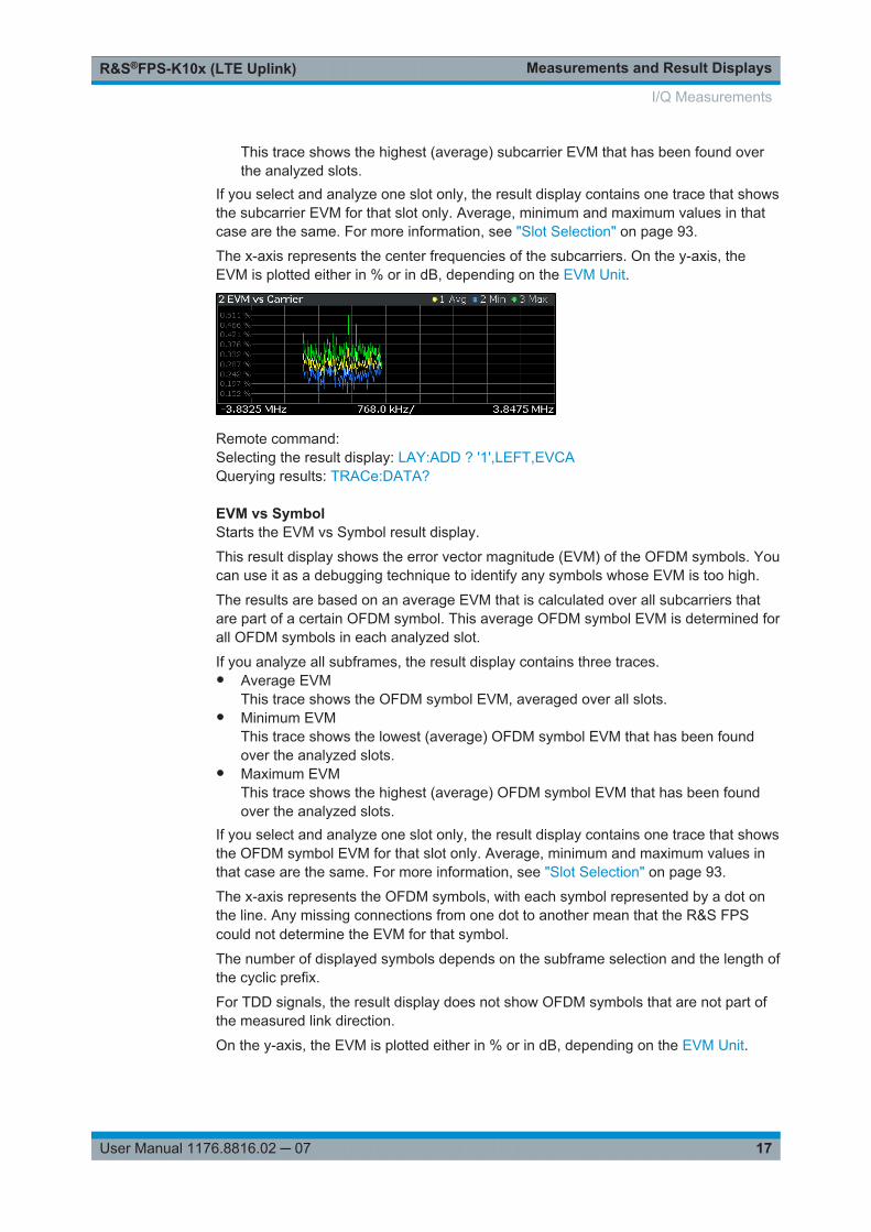
EVM vs CarrierStarts the EVM vs Carrier result display.
This result display shows the error vector magnitude (EVM) of the subcarriers. With thehelp of a marker, you can use it as a debugging technique to identify any subcarrierswhose EVM is too high.
The results are based on an average EVM that is calculated over the resource ele-ments for each subcarrier. This average subcarrier EVM is determined for each ana-lyzed slot in the capture buffer.
If you analyze all slots, the result display contains three traces.● Average EVM
This trace shows the subcarrier EVM, averaged over all slots.● Minimum EVM
This trace shows the lowest (average) subcarrier EVM that has been found overthe analyzed slots.
● Maximum EVM
I/Q Measurements
Measurements and Result DisplaysR&S®FPS-K10x (LTE Uplink)
17User Manual 1176.8816.02 ─ 07
This trace shows the highest (average) subcarrier EVM that has been found overthe analyzed slots.
If you select and analyze one slot only, the result display contains one trace that showsthe subcarrier EVM for that slot only. Average, minimum and maximum values in thatcase are the same. For more information, see "Slot Selection" on page 93.
The x-axis represents the center frequencies of the subcarriers. On the y-axis, theEVM is plotted either in % or in dB, depending on the EVM Unit.
Remote command: Selecting the result display: LAY:ADD ? '1',LEFT,EVCAQuerying results: TRACe:DATA?
EVM vs SymbolStarts the EVM vs Symbol result display.
This result display shows the error vector magnitude (EVM) of the OFDM symbols. Youcan use it as a debugging technique to identify any symbols whose EVM is too high.
The results are based on an average EVM that is calculated over all subcarriers thatare part of a certain OFDM symbol. This average OFDM symbol EVM is determined forall OFDM symbols in each analyzed slot.
If you analyze all subframes, the result display contains three traces.● Average EVM
This trace shows the OFDM symbol EVM, averaged over all slots.● Minimum EVM
This trace shows the lowest (average) OFDM symbol EVM that has been foundover the analyzed slots.
● Maximum EVMThis trace shows the highest (average) OFDM symbol EVM that has been foundover the analyzed slots.
If you select and analyze one slot only, the result display contains one trace that showsthe OFDM symbol EVM for that slot only. Average, minimum and maximum values inthat case are the same. For more information, see "Slot Selection" on page 93.
The x-axis represents the OFDM symbols, with each symbol represented by a dot onthe line. Any missing connections from one dot to another mean that the R&S FPScould not determine the EVM for that symbol.
The number of displayed symbols depends on the subframe selection and the length ofthe cyclic prefix.
For TDD signals, the result display does not show OFDM symbols that are not part ofthe measured link direction.
On the y-axis, the EVM is plotted either in % or in dB, depending on the EVM Unit.
I/Q Measurements
Measurements and Result DisplaysR&S®FPS-K10x (LTE Uplink)
18User Manual 1176.8816.02 ─ 07
Remote command: Selecting the result display: LAY:ADD ? '1',LEFT,EVSYQuerying results: TRACe:DATA?
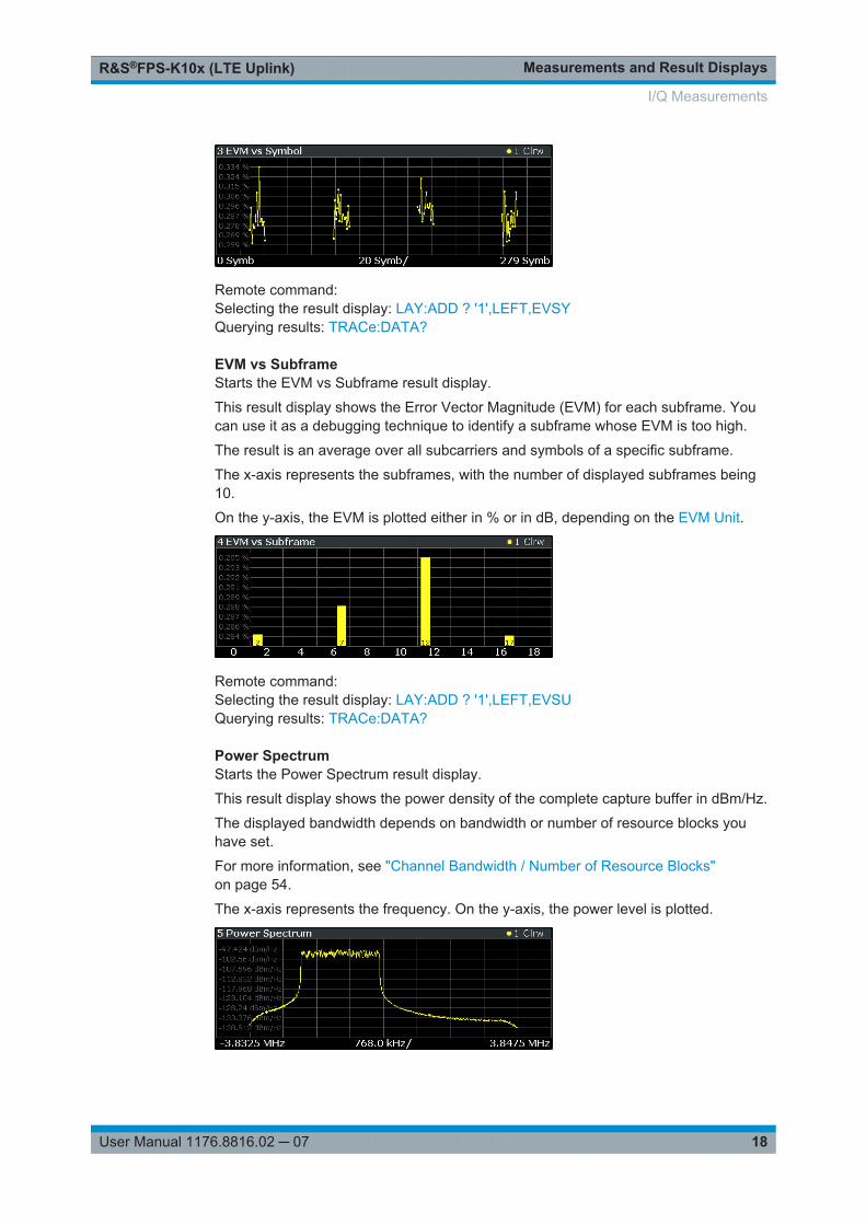
EVM vs SubframeStarts the EVM vs Subframe result display.
This result display shows the Error Vector Magnitude (EVM) for each subframe. Youcan use it as a debugging technique to identify a subframe whose EVM is too high.
The result is an average over all subcarriers and symbols of a specific subframe.
The x-axis represents the subframes, with the number of displayed subframes being10.
On the y-axis, the EVM is plotted either in % or in dB, depending on the EVM Unit.
Remote command: Selecting the result display: LAY:ADD ? '1',LEFT,EVSUQuerying results: TRACe:DATA?
Power SpectrumStarts the Power Spectrum result display.
This result display shows the power density of the complete capture buffer in dBm/Hz.
The displayed bandwidth depends on bandwidth or number of resource blocks youhave set.
For more information, see "Channel Bandwidth / Number of Resource Blocks"on page 54.
The x-axis represents the frequency. On the y-axis, the power level is plotted.
I/Q Measurements
Measurements and Result DisplaysR&S®FPS-K10x (LTE Uplink)
19User Manual 1176.8816.02 ─ 07
Remote command: Selecting the result display: LAY:ADD ? '1',LEFT,PSPEQuerying results: TRACe:DATA?
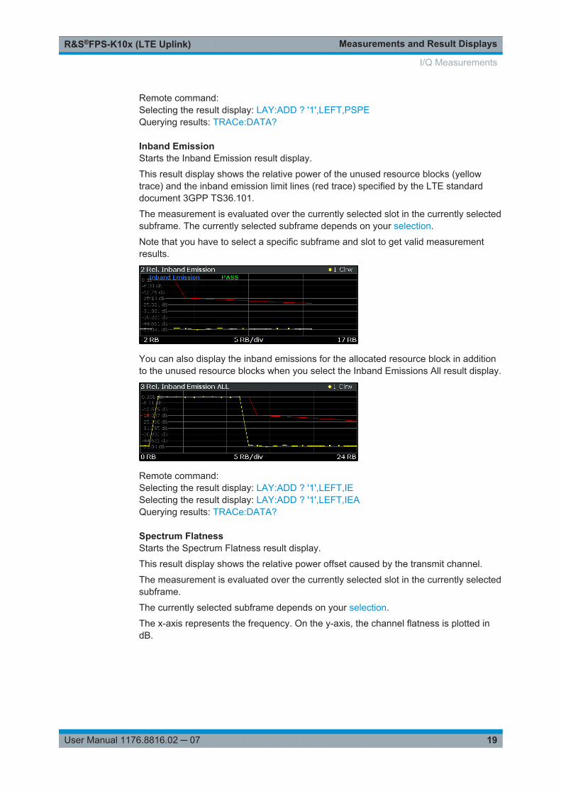
Inband EmissionStarts the Inband Emission result display.
This result display shows the relative power of the unused resource blocks (yellowtrace) and the inband emission limit lines (red trace) specified by the LTE standarddocument 3GPP TS36.101.
The measurement is evaluated over the currently selected slot in the currently selectedsubframe. The currently selected subframe depends on your selection.
Note that you have to select a specific subframe and slot to get valid measurementresults.
You can also display the inband emissions for the allocated resource block in additionto the unused resource blocks when you select the Inband Emissions All result display.
Remote command: Selecting the result display: LAY:ADD ? '1',LEFT,IESelecting the result display: LAY:ADD ? '1',LEFT,IEAQuerying results: TRACe:DATA?
Spectrum FlatnessStarts the Spectrum Flatness result display.
This result display shows the relative power offset caused by the transmit channel.
The measurement is evaluated over the currently selected slot in the currently selectedsubframe.
The currently selected subframe depends on your selection.
The x-axis represents the frequency. On the y-axis, the channel flatness is plotted indB.
I/Q Measurements
Measurements and Result DisplaysR&S®FPS-K10x (LTE Uplink)
20User Manual 1176.8816.02 ─ 07
Note that the limit lines are only displayed if you match the Operating Band to the cen-ter frequency. Limits are defined for each operating band in the standard.
The shape of the limit line is different when "Extreme Conditions" on page 56 are on.
Remote command: Selecting the result display: LAY:ADD ? '1',LEFT,SFLQuerying results: TRACe:DATA?
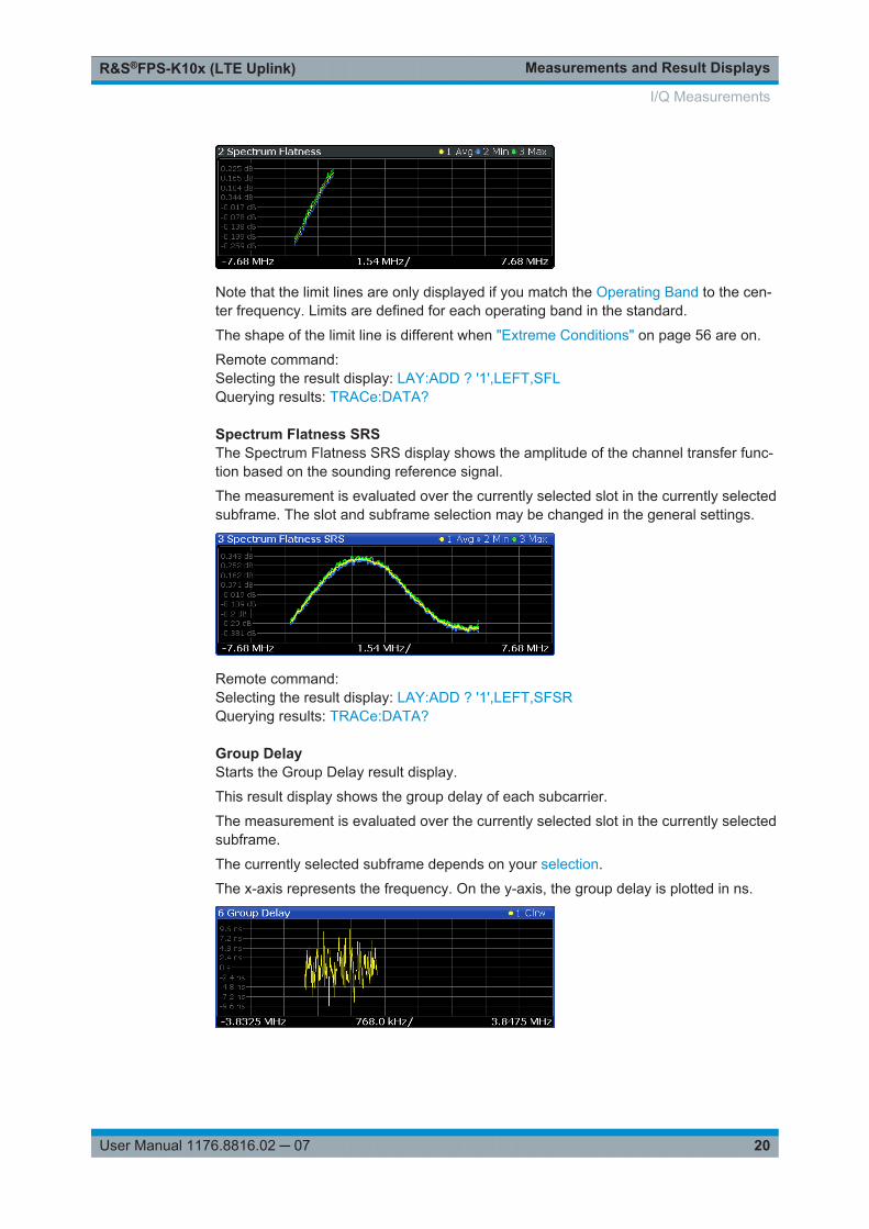
Spectrum Flatness SRSThe Spectrum Flatness SRS display shows the amplitude of the channel transfer func-tion based on the sounding reference signal.
The measurement is evaluated over the currently selected slot in the currently selectedsubframe. The slot and subframe selection may be changed in the general settings.
Remote command: Selecting the result display: LAY:ADD ? '1',LEFT,SFSRQuerying results: TRACe:DATA?
Group DelayStarts the Group Delay result display.
This result display shows the group delay of each subcarrier.
The measurement is evaluated over the currently selected slot in the currently selectedsubframe.
The currently selected subframe depends on your selection.
The x-axis represents the frequency. On the y-axis, the group delay is plotted in ns.
I/Q Measurements
Measurements and Result DisplaysR&S®FPS-K10x (LTE Uplink)
21User Manual 1176.8816.02 ─ 07
Remote command: Selecting the result display: LAY:ADD ? '1',LEFT,GDELQuerying results: TRACe:DATA?
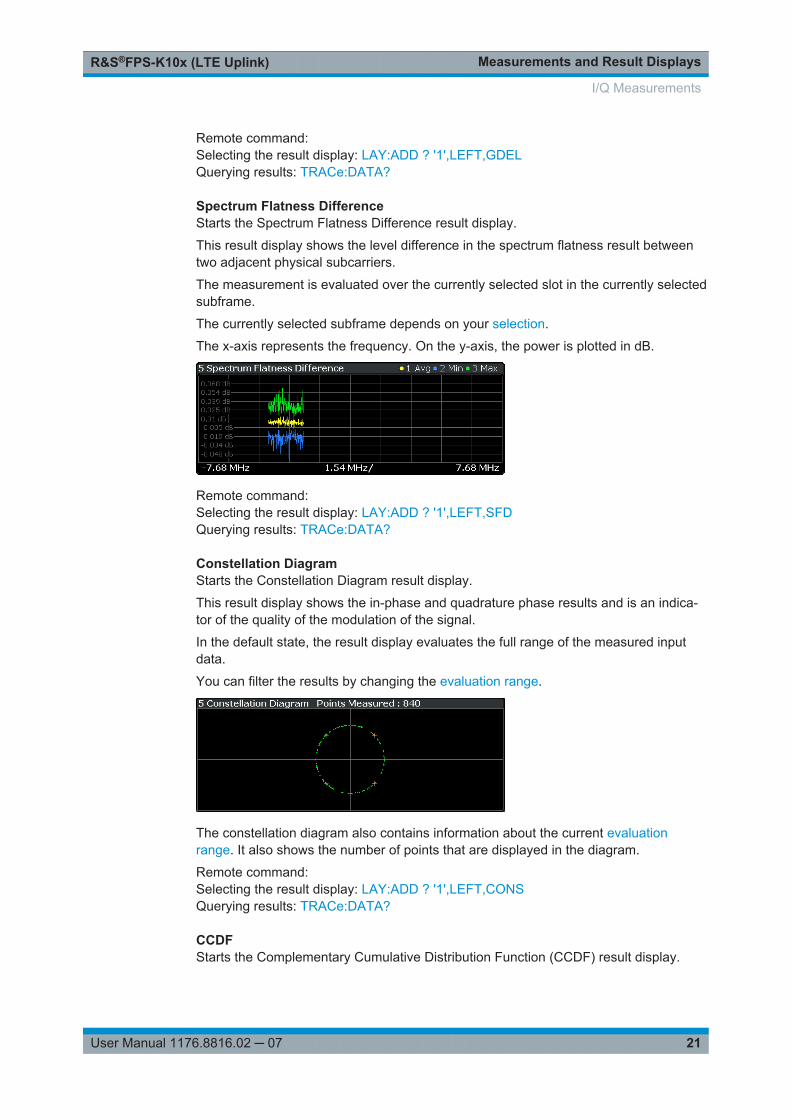
Spectrum Flatness DifferenceStarts the Spectrum Flatness Difference result display.
This result display shows the level difference in the spectrum flatness result betweentwo adjacent physical subcarriers.
The measurement is evaluated over the currently selected slot in the currently selectedsubframe.
The currently selected subframe depends on your selection.
The x-axis represents the frequency. On the y-axis, the power is plotted in dB.
Remote command: Selecting the result display: LAY:ADD ? '1',LEFT,SFDQuerying results: TRACe:DATA?
Constellation DiagramStarts the Constellation Diagram result display.
This result display shows the in-phase and quadrature phase results and is an indica-tor of the quality of the modulation of the signal.
In the default state, the result display evaluates the full range of the measured inputdata.
You can filter the results by changing the evaluation range.
The constellation diagram also contains information about the current evaluationrange. It also shows the number of points that are displayed in the diagram.
Remote command: Selecting the result display: LAY:ADD ? '1',LEFT,CONSQuerying results: TRACe:DATA?
CCDFStarts the Complementary Cumulative Distribution Function (CCDF) result display.
I/Q Measurements
Measurements and Result DisplaysR&S®FPS-K10x (LTE Uplink)
22User Manual 1176.8816.02 ─ 07
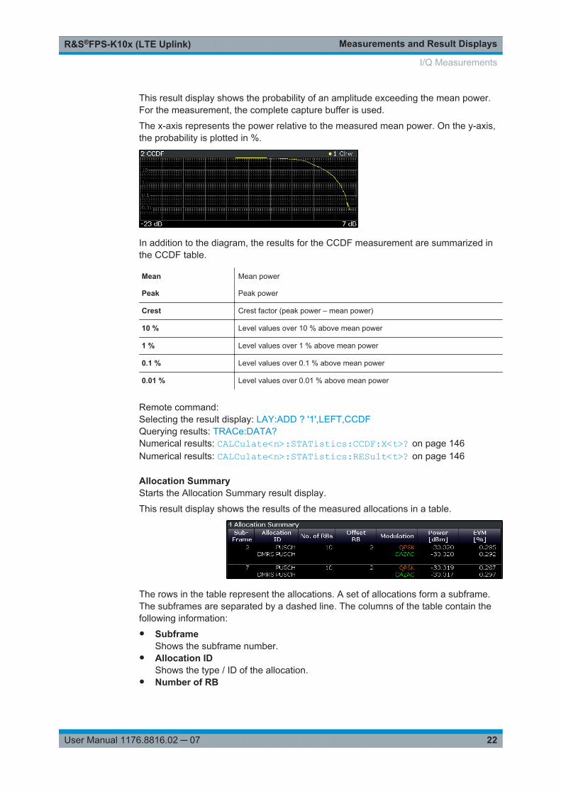
This result display shows the probability of an amplitude exceeding the mean power.For the measurement, the complete capture buffer is used.
The x-axis represents the power relative to the measured mean power. On the y-axis,the probability is plotted in %.
In addition to the diagram, the results for the CCDF measurement are summarized inthe CCDF table.
Mean Mean power
Peak Peak power
Crest Crest factor (peak power – mean power)
10 % Level values over 10 % above mean power
1 % Level values over 1 % above mean power
0.1 % Level values over 0.1 % above mean power
0.01 % Level values over 0.01 % above mean power
Remote command: Selecting the result display: LAY:ADD ? '1',LEFT,CCDFQuerying results: TRACe:DATA?Numerical results: CALCulate<n>:STATistics:CCDF:X<t>? on page 146Numerical results: CALCulate<n>:STATistics:RESult<t>? on page 146
Allocation SummaryStarts the Allocation Summary result display.
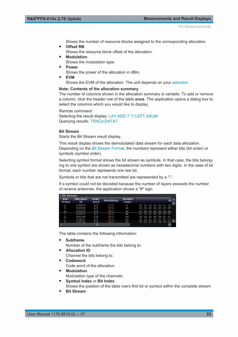
This result display shows the results of the measured allocations in a table.
The rows in the table represent the allocations. A set of allocations form a subframe.The subframes are separated by a dashed line. The columns of the table contain thefollowing information:● Subframe
Shows the subframe number.● Allocation ID
Shows the type / ID of the allocation.● Number of RB
I/Q Measurements
Measurements and Result DisplaysR&S®FPS-K10x (LTE Uplink)
23User Manual 1176.8816.02 ─ 07
Shows the number of resource blocks assigned to the corresponding allocation.● Offset RB
Shows the resource block offset of the allocation.● Modulation
Shows the modulation type.● Power
Shows the power of the allocation in dBm.● EVM
Shows the EVM of the allocation. The unit depends on your selection.Note: Contents of the allocation summaryThe number of columns shown in the allocation summary is variable. To add or removea column, click the header row of the table once. The application opens a dialog box toselect the columns which you would like to display.
Remote command: Selecting the result display: LAY:ADD ? '1',LEFT,ASUMQuerying results: TRACe:DATA?
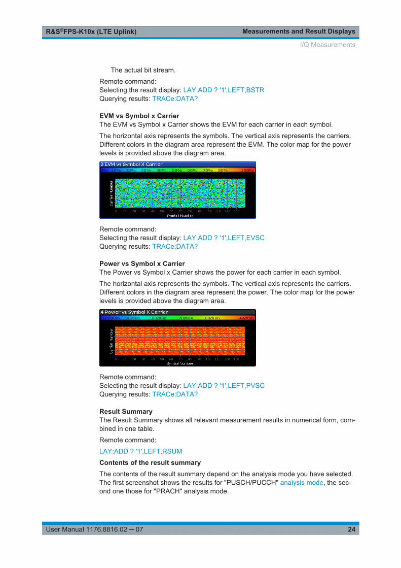
Bit StreamStarts the Bit Stream result display.
This result display shows the demodulated data stream for each data allocation.Depending on the Bit Stream Format, the numbers represent either bits (bit order) orsymbols (symbol order).
Selecting symbol format shows the bit stream as symbols. In that case, the bits belong-ing to one symbol are shown as hexadecimal numbers with two digits. In the case of bitformat, each number represents one raw bit.
Symbols or bits that are not transmitted are represented by a "-".
If a symbol could not be decoded because the number of layers exceeds the numberof receive antennas, the application shows a "#" sign.
The table contains the following information:● Subframe
Number of the subframe the bits belong to.● Allocation ID
Channel the bits belong to.● Codeword
Code word of the allocation.● Modulation
Modulation type of the channels.● Symbol Index or Bit Index
Shows the position of the table row's first bit or symbol within the complete stream.● Bit Stream
I/Q Measurements
Measurements and Result DisplaysR&S®FPS-K10x (LTE Uplink)
24User Manual 1176.8816.02 ─ 07
The actual bit stream.
Remote command: Selecting the result display: LAY:ADD ? '1',LEFT,BSTRQuerying results: TRACe:DATA?
EVM vs Symbol x CarrierThe EVM vs Symbol x Carrier shows the EVM for each carrier in each symbol.
The horizontal axis represents the symbols. The vertical axis represents the carriers.Different colors in the diagram area represent the EVM. The color map for the powerlevels is provided above the diagram area.
Remote command: Selecting the result display: LAY:ADD ? '1',LEFT,EVSCQuerying results: TRACe:DATA?
Power vs Symbol x CarrierThe Power vs Symbol x Carrier shows the power for each carrier in each symbol.
The horizontal axis represents the symbols. The vertical axis represents the carriers.Different colors in the diagram area represent the power. The color map for the powerlevels is provided above the diagram area.
Remote command: Selecting the result display: LAY:ADD ? '1',LEFT,PVSCQuerying results: TRACe:DATA?
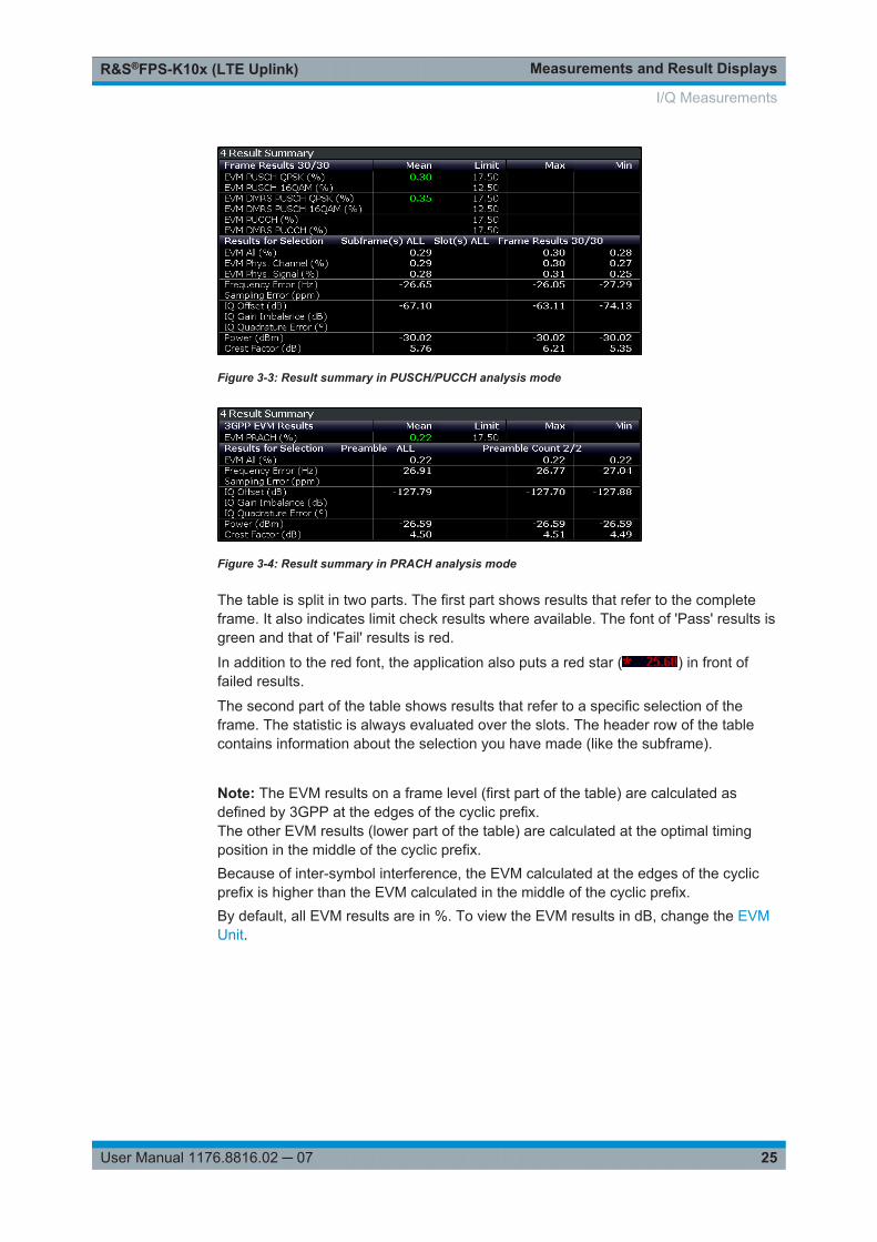
Result SummaryThe Result Summary shows all relevant measurement results in numerical form, com-bined in one table.
Remote command:
LAY:ADD ? '1',LEFT,RSUM
Contents of the result summaryThe contents of the result summary depend on the analysis mode you have selected.The first screenshot shows the results for "PUSCH/PUCCH" analysis mode, the sec-ond one those for "PRACH" analysis mode.
I/Q Measurements
Measurements and Result DisplaysR&S®FPS-K10x (LTE Uplink)
25User Manual 1176.8816.02 ─ 07
Figure 3-3: Result summary in PUSCH/PUCCH analysis mode
Figure 3-4: Result summary in PRACH analysis mode
The table is split in two parts. The first part shows results that refer to the completeframe. It also indicates limit check results where available. The font of 'Pass' results isgreen and that of 'Fail' results is red.
In addition to the red font, the application also puts a red star ( ) in front offailed results.
The second part of the table shows results that refer to a specific selection of theframe. The statistic is always evaluated over the slots. The header row of the tablecontains information about the selection you have made (like the subframe). Note: The EVM results on a frame level (first part of the table) are calculated asdefined by 3GPP at the edges of the cyclic prefix.The other EVM results (lower part of the table) are calculated at the optimal timingposition in the middle of the cyclic prefix.Because of inter-symbol interference, the EVM calculated at the edges of the cyclicprefix is higher than the EVM calculated in the middle of the cyclic prefix.By default, all EVM results are in %. To view the EVM results in dB, change the EVMUnit.
I/Q Measurements

Measurements and Result DisplaysR&S®FPS-K10x (LTE Uplink)
26User Manual 1176.8816.02 ─ 07
Table 3-1: Result summary: part containing results as defined by 3GPP (PUSCH/PUCCH analysis)
EVM PUSCH QPSK Shows the EVM for all QPSK-modulated resource elements of the PUSCHchannel in the analyzed frame.
FETCh[:CC<cc>]:SUMMary:EVM:USQP[:AVERage]? on page 136
EVM PUSCH 16QAM Shows the EVM for all 16QAM-modulated resource elements of the PUSCHchannel in the analyzed frame.
FETCh[:CC<cc>]:SUMMary:EVM:USST[:AVERage]? on page 136
EVM PUSCH 64QAM Shows the EVM for all 64QAM-modulated resource elements of the PUSCHchannel in the analyzed frame.
FETCh[:CC<cc>]:SUMMary:EVM:USSF[:AVERage]? on page 136
EVM PUSCH 256QAM Shows the EVM for all 256QAM-modulated resource elements of the PUSCHchannel in the analyzed frame.
FETCh[:CC<cc>]:SUMMary:EVM:USTS[:AVERage]? on page 137
EVM DMRS PUSCH QPSK Shows the EVM of all DMRS resource elements with QPSK modulation of thePUSCH in the analyzed frame.
FETCh[:CC<cc>]:SUMMary:EVM:SDQP[:AVERage]? on page 133
EVM DMRS PUSCH 16QAM Shows the EVM of all DMRS resource elements with 16QAM modulation ofthe PUSCH in the analyzed frame.
FETCh[:CC<cc>]:SUMMary:EVM:SDST[:AVERage]? on page 134
EVM DMRS PUSCH 64QAM Shows the EVM of all DMRS resource elements with 64QAM modulation ofthe PUSCH in the analyzed frame.
FETCh[:CC<cc>]:SUMMary:EVM:SDSF[:AVERage]? on page 134
EVM DMRS PUSCH256QAM
Shows the EVM of all DMRS resource elements with 256QAM modulation ofthe PUSCH in the analyzed frame.
FETCh[:CC<cc>]:SUMMary:EVM:SDTS[:AVERage]? on page 134
EVM PUCCH Shows the EVM of all resource elements of the PUCCH channel in the ana-lyzed frame.
FETCh[:CC<cc>]:SUMMary:EVM:UCCH[:AVERage]? on page 135
EVM DMRS PUCCH Shows the EVM of all DMRS resource elements of the PUCCH channel in theanalyzed frame.
FETCh[:CC<cc>]:SUMMary:EVM:UCCD[:AVERage]? on page 135
Table 3-2: Result summary: part containing results as defined by 3GPP (PRACH analysis)
EVM PRACH Shows the EVM of all resource elements of the PRACH channel in the ana-lyzed frame.
FETCh[:CC<cc>]:SUMMary:EVM:UPRA[:AVERage]? on page 135
I/Q Measurements
Measurements and Result DisplaysR&S®FPS-K10x (LTE Uplink)
27User Manual 1176.8816.02 ─ 07
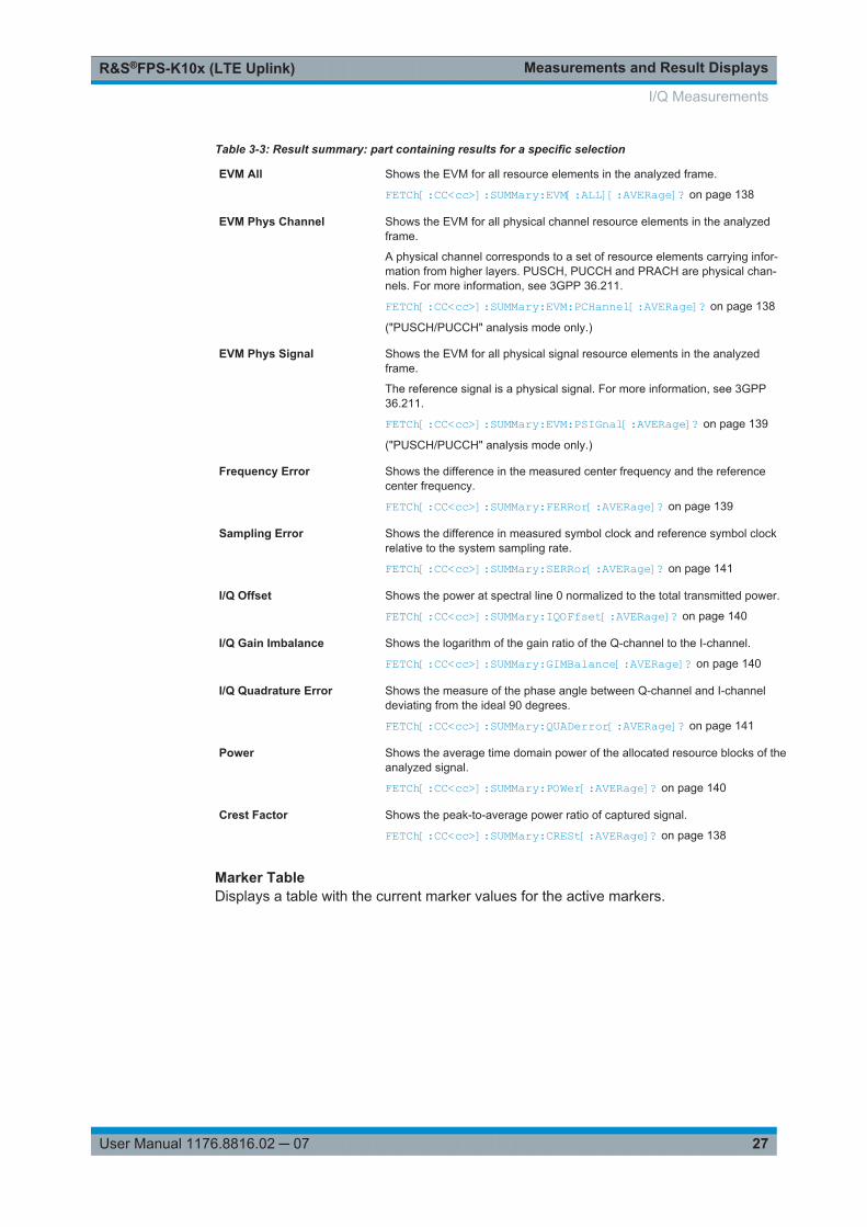
Table 3-3: Result summary: part containing results for a specific selection
EVM All Shows the EVM for all resource elements in the analyzed frame.
FETCh[:CC<cc>]:SUMMary:EVM[:ALL][:AVERage]? on page 138
EVM Phys Channel Shows the EVM for all physical channel resource elements in the analyzedframe.
A physical channel corresponds to a set of resource elements carrying infor-mation from higher layers. PUSCH, PUCCH and PRACH are physical chan-nels. For more information, see 3GPP 36.211.
FETCh[:CC<cc>]:SUMMary:EVM:PCHannel[:AVERage]? on page 138
("PUSCH/PUCCH" analysis mode only.)
EVM Phys Signal Shows the EVM for all physical signal resource elements in the analyzedframe.
The reference signal is a physical signal. For more information, see 3GPP36.211.
FETCh[:CC<cc>]:SUMMary:EVM:PSIGnal[:AVERage]? on page 139
("PUSCH/PUCCH" analysis mode only.)
Frequency Error Shows the difference in the measured center frequency and the referencecenter frequency.
FETCh[:CC<cc>]:SUMMary:FERRor[:AVERage]? on page 139
Sampling Error Shows the difference in measured symbol clock and reference symbol clockrelative to the system sampling rate.
FETCh[:CC<cc>]:SUMMary:SERRor[:AVERage]? on page 141
I/Q Offset Shows the power at spectral line 0 normalized to the total transmitted power.
FETCh[:CC<cc>]:SUMMary:IQOFfset[:AVERage]? on page 140
I/Q Gain Imbalance Shows the logarithm of the gain ratio of the Q-channel to the I-channel.
FETCh[:CC<cc>]:SUMMary:GIMBalance[:AVERage]? on page 140
I/Q Quadrature Error Shows the measure of the phase angle between Q-channel and I-channeldeviating from the ideal 90 degrees.
FETCh[:CC<cc>]:SUMMary:QUADerror[:AVERage]? on page 141
Power Shows the average time domain power of the allocated resource blocks of theanalyzed signal.
FETCh[:CC<cc>]:SUMMary:POWer[:AVERage]? on page 140
Crest Factor Shows the peak-to-average power ratio of captured signal.
FETCh[:CC<cc>]:SUMMary:CRESt[:AVERage]? on page 138
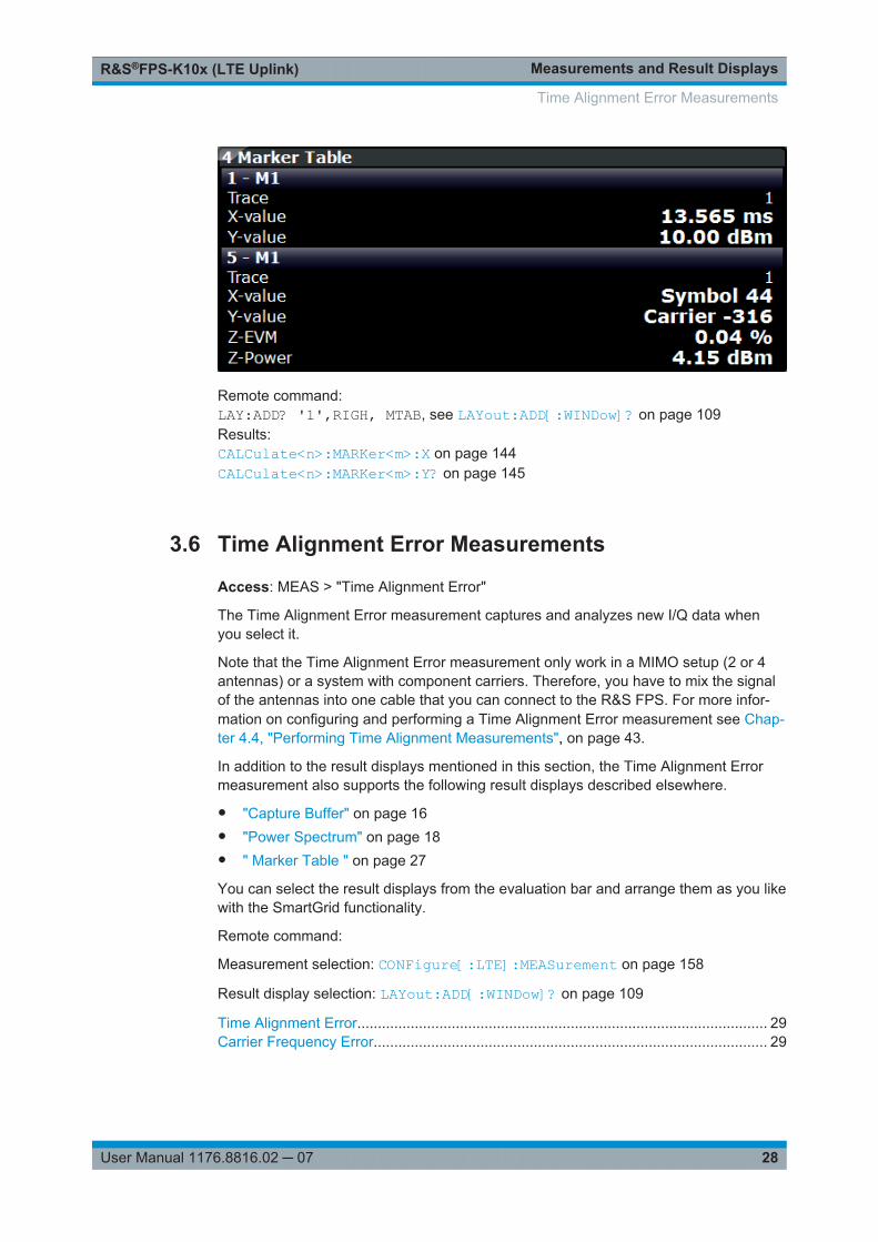
Marker TableDisplays a table with the current marker values for the active markers.
I/Q Measurements
Measurements and Result DisplaysR&S®FPS-K10x (LTE Uplink)
28User Manual 1176.8816.02 ─ 07
Remote command: LAY:ADD? '1',RIGH, MTAB, see LAYout:ADD[:WINDow]? on page 109Results:CALCulate<n>:MARKer<m>:X on page 144CALCulate<n>:MARKer<m>:Y? on page 145
3.6 Time Alignment Error Measurements
Access: MEAS > "Time Alignment Error"
The Time Alignment Error measurement captures and analyzes new I/Q data whenyou select it.
Note that the Time Alignment Error measurement only work in a MIMO setup (2 or 4antennas) or a system with component carriers. Therefore, you have to mix the signalof the antennas into one cable that you can connect to the R&S FPS. For more infor-mation on configuring and performing a Time Alignment Error measurement see Chap-ter 4.4, "Performing Time Alignment Measurements", on page 43.
In addition to the result displays mentioned in this section, the Time Alignment Errormeasurement also supports the following result displays described elsewhere.
● "Capture Buffer" on page 16● "Power Spectrum" on page 18● " Marker Table " on page 27
You can select the result displays from the evaluation bar and arrange them as you likewith the SmartGrid functionality.
Remote command:
Measurement selection: CONFigure[:LTE]:MEASurement on page 158
Result display selection: LAYout:ADD[:WINDow]? on page 109
Time Alignment Error.................................................................................................... 29Carrier Frequency Error................................................................................................ 29
Time Alignment Error Measurements
Measurements and Result DisplaysR&S®FPS-K10x (LTE Uplink)
29User Manual 1176.8816.02 ─ 07
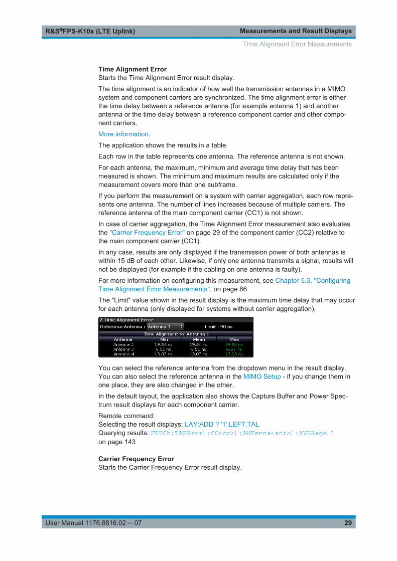
Time Alignment ErrorStarts the Time Alignment Error result display.
The time alignment is an indicator of how well the transmission antennas in a MIMOsystem and component carriers are synchronized. The time alignment error is eitherthe time delay between a reference antenna (for example antenna 1) and anotherantenna or the time delay between a reference component carrier and other compo-nent carriers.
More information.
The application shows the results in a table.
Each row in the table represents one antenna. The reference antenna is not shown.
For each antenna, the maximum, minimum and average time delay that has beenmeasured is shown. The minimum and maximum results are calculated only if themeasurement covers more than one subframe.
If you perform the measurement on a system with carrier aggregation, each row repre-sents one antenna. The number of lines increases because of multiple carriers. Thereference antenna of the main component carrier (CC1) is not shown.
In case of carrier aggregation, the Time Alignment Error measurement also evaluatesthe "Carrier Frequency Error" on page 29 of the component carrier (CC2) relative tothe main component carrier (CC1).
In any case, results are only displayed if the transmission power of both antennas iswithin 15 dB of each other. Likewise, if only one antenna transmits a signal, results willnot be displayed (for example if the cabling on one antenna is faulty).
For more information on configuring this measurement, see Chapter 5.3, "ConfiguringTime Alignment Error Measurements", on page 86.
The "Limit" value shown in the result display is the maximum time delay that may occurfor each antenna (only displayed for systems without carrier aggregation).
You can select the reference antenna from the dropdown menu in the result display.You can also select the reference antenna in the MIMO Setup - if you change them inone place, they are also changed in the other.
In the default layout, the application also shows the Capture Buffer and Power Spec-trum result displays for each component carrier.
Remote command: Selecting the result displays: LAY:ADD ? '1',LEFT,TALQuerying results: FETCh:TAERror[:CC<cc>]:ANTenna<ant>[:AVERage]?on page 143
Carrier Frequency ErrorStarts the Carrier Frequency Error result display.
Time Alignment Error Measurements

Measurements and Result DisplaysR&S®FPS-K10x (LTE Uplink)
30User Manual 1176.8816.02 ─ 07
The carrier frequency error is an indicator of how well the component carriers in a sys-tem with carrier aggregation are synchronized. The Carrier Frequency Error is the fre-quency deviation between a reference carrier (usually Component Carrier 1) andanother component carrier.
The application shows the results in a table.
For each component carrier, the application adds two rows to the table.● The first row shows the lowest, average and highest frequency error that has been
measured in Hz. In addition, the limit defined by 3GPP for that scenario is dis-played. Note that the application always tests against the highest measured value;if the limit has been violated, the font color of the maximum value turns red.If you measure a single slot only, the lowest, average and highest valued are thesame.
● The second row shows the lowest, average and highest frequency error that hasbeen measured in ppm. In addition, the limit defined by 3GPP for that scenario isdisplayed.If you measure a single slot only, the lowest, average and highest valued are thesame.
The reference component carrier is not represented in the table.
Remote command: In Hz: FETCh:FERRor[:CC<cc>][:AVERage]? on page 143In ppm: FETCh:FEPPm[:CC<cc>][:AVERage]? on page 142
3.7 Frequency Sweep Measurements
Access (ACLR): MEAS > "Channel Power ACLR"
Access (MC ACLR): MEAS > "Multi Carrier ACLR"
Access (SEM): MEAS > "Spectrum Emission Mask"
The Spectrum Emission Mask (SEM) and Adjacent Channel Leakage Ratio (ACLR)measurements are the only frequency sweep measurements available for the LTEmeasurement application. They do not use the I/Q data all other measurements use.Instead those measurements sweep the frequency spectrum every time you run a newmeasurement. Therefore it is not possible to to run an I/Q measurement and then viewthe results in the frequency sweep measurements and vice-versa. Also because eachof the frequency sweep measurements uses different settings to obtain signal data it isnot possible to run a frequency sweep measurement and view the results in anotherfrequency sweep measurement.
Frequency sweep measurements are available if RF input is selected.
In addition to the frequency sweep result displays (graphical and numerical, see thedescription below), the following result displays are also supported.● Marker Table● Marker Peak List
Both result displays have the same contents as the Spectrum application.
Remote command:
Frequency Sweep Measurements
Measurements and Result DisplaysR&S®FPS-K10x (LTE Uplink)
31User Manual 1176.8816.02 ─ 07
Measurement selection: CONFigure[:LTE]:MEASurement on page 158
Result display selection: LAYout:ADD[:WINDow]? on page 109
ACLR.............................................................................................................................31Spectrum Mask............................................................................................................. 32Multi Carrier ACLR........................................................................................................ 34Marker Peak List .......................................................................................................... 35
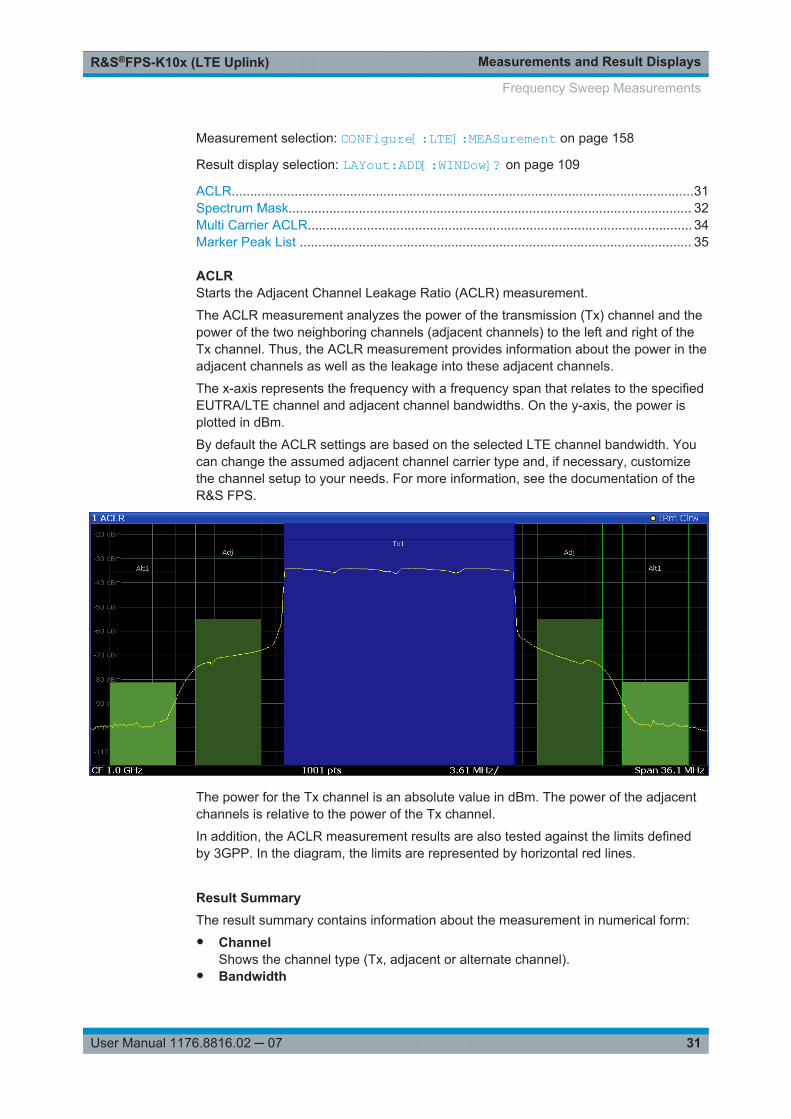
ACLRStarts the Adjacent Channel Leakage Ratio (ACLR) measurement.
The ACLR measurement analyzes the power of the transmission (Tx) channel and thepower of the two neighboring channels (adjacent channels) to the left and right of theTx channel. Thus, the ACLR measurement provides information about the power in theadjacent channels as well as the leakage into these adjacent channels.
The x-axis represents the frequency with a frequency span that relates to the specifiedEUTRA/LTE channel and adjacent channel bandwidths. On the y-axis, the power isplotted in dBm.
By default the ACLR settings are based on the selected LTE channel bandwidth. Youcan change the assumed adjacent channel carrier type and, if necessary, customizethe channel setup to your needs. For more information, see the documentation of theR&S FPS.
The power for the Tx channel is an absolute value in dBm. The power of the adjacentchannels is relative to the power of the Tx channel.
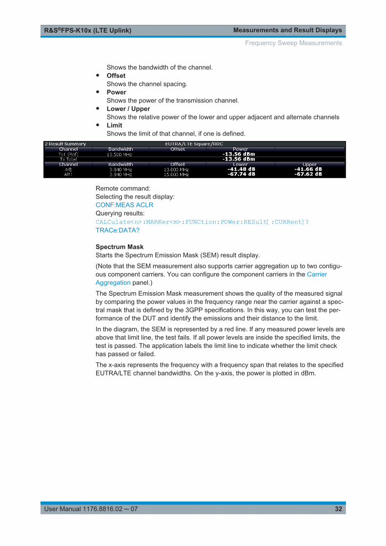
In addition, the ACLR measurement results are also tested against the limits definedby 3GPP. In the diagram, the limits are represented by horizontal red lines. Result SummaryThe result summary contains information about the measurement in numerical form:● Channel
Shows the channel type (Tx, adjacent or alternate channel).● Bandwidth
Frequency Sweep Measurements
Measurements and Result DisplaysR&S®FPS-K10x (LTE Uplink)
32User Manual 1176.8816.02 ─ 07
Shows the bandwidth of the channel.● Offset
Shows the channel spacing.● Power
Shows the power of the transmission channel.● Lower / Upper
Shows the relative power of the lower and upper adjacent and alternate channels● Limit
Shows the limit of that channel, if one is defined.
Remote command: Selecting the result display:CONF:MEAS ACLRQuerying results:CALCulate<n>:MARKer<m>:FUNCtion:POWer:RESult[:CURRent]?TRACe:DATA?
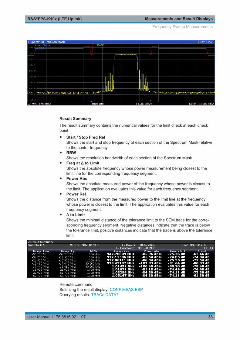
Spectrum MaskStarts the Spectrum Emission Mask (SEM) result display.
(Note that the SEM measurement also supports carrier aggregation up to two contigu-ous component carriers. You can configure the component carriers in the CarrierAggregation panel.)
The Spectrum Emission Mask measurement shows the quality of the measured signalby comparing the power values in the frequency range near the carrier against a spec-tral mask that is defined by the 3GPP specifications. In this way, you can test the per-formance of the DUT and identify the emissions and their distance to the limit.
In the diagram, the SEM is represented by a red line. If any measured power levels areabove that limit line, the test fails. If all power levels are inside the specified limits, thetest is passed. The application labels the limit line to indicate whether the limit checkhas passed or failed.
The x-axis represents the frequency with a frequency span that relates to the specifiedEUTRA/LTE channel bandwidths. On the y-axis, the power is plotted in dBm.
Frequency Sweep Measurements
Measurements and Result DisplaysR&S®FPS-K10x (LTE Uplink)
33User Manual 1176.8816.02 ─ 07
Result SummaryThe result summary contains the numerical values for the limit check at each checkpoint:● Start / Stop Freq Rel
Shows the start and stop frequency of each section of the Spectrum Mask relativeto the center frequency.
● RBWShows the resolution bandwidth of each section of the Spectrum Mask
● Freq at Δ to LimitShows the absolute frequency whose power measurement being closest to thelimit line for the corresponding frequency segment.
● Power AbsShows the absolute measured power of the frequency whose power is closest tothe limit. The application evaluates this value for each frequency segment.
● Power RelShows the distance from the measured power to the limit line at the frequencywhose power is closest to the limit. The application evaluates this value for eachfrequency segment.
● Δ to LimitShows the minimal distance of the tolerance limit to the SEM trace for the corre-sponding frequency segment. Negative distances indicate that the trace is belowthe tolerance limit, positive distances indicate that the trace is above the tolerancelimit.
Remote command: Selecting the result display: CONF:MEAS ESPQuerying results: TRACe:DATA?
Frequency Sweep Measurements
Measurements and Result DisplaysR&S®FPS-K10x (LTE Uplink)
34User Manual 1176.8816.02 ─ 07
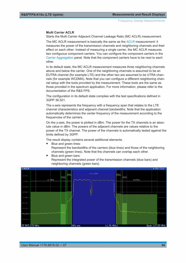
Multi Carrier ACLRStarts the Multi Carrier Adjacent Channel Leakage Ratio (MC ACLR) measurement.
The MC ACLR measurement is basically the same as the ACLR measurement: itmeasures the power of the transmission channels and neighboring channels and theireffect on each other. Instead of measuring a single carrier, the MC ACLR measurestwo contiguous component carriers. You can configure the component carriers in theCarrier Aggregation panel. Note that the component carriers have to be next to eachother.
In its default state, the MC ACLR measurement measures three neighboring channelsabove and below the carrier. One of the neighboring channels is assumed to be anEUTRA channel (for example LTE) and the other two are assumed to be UTRA chan-nels (for example WCDMA). Note that you can configure a different neighboring chan-nel setup with the tools provided by the measurement. These tools are the same asthose provided in the spectrum application. For more information, please refer to thedocumentation of the R&S FPS.
The configuration in its default state complies with the test specifications defined in3GPP 36.521.
The x-axis represents the frequency with a frequency span that relates to the LTEchannel characteristics and adjacent channel bandwidths. Note that the applicationautomatically determines the center frequency of the measurement according to thefrequencies of the carriers.
On the y-axis, the power is plotted in dBm. The power for the TX channels is an abso-lute value in dBm. The powers of the adjacent channels are values relative to thepower of the TX channel. The power of the channels is automatically tested against thelimits defined by 3GPP.
The result display contains several additional elements.● Blue and green lines:
Represent the bandwidths of the carriers (blue lines) and those of the neighboringchannels (green lines). Note that the channels can overlap each other.
● Blue and green bars:Represent the integrated power of the transmission channels (blue bars) andneighboring channels (green bars).
Frequency Sweep Measurements
Measurements and Result DisplaysR&S®FPS-K10x (LTE Uplink)
35User Manual 1176.8816.02 ─ 07
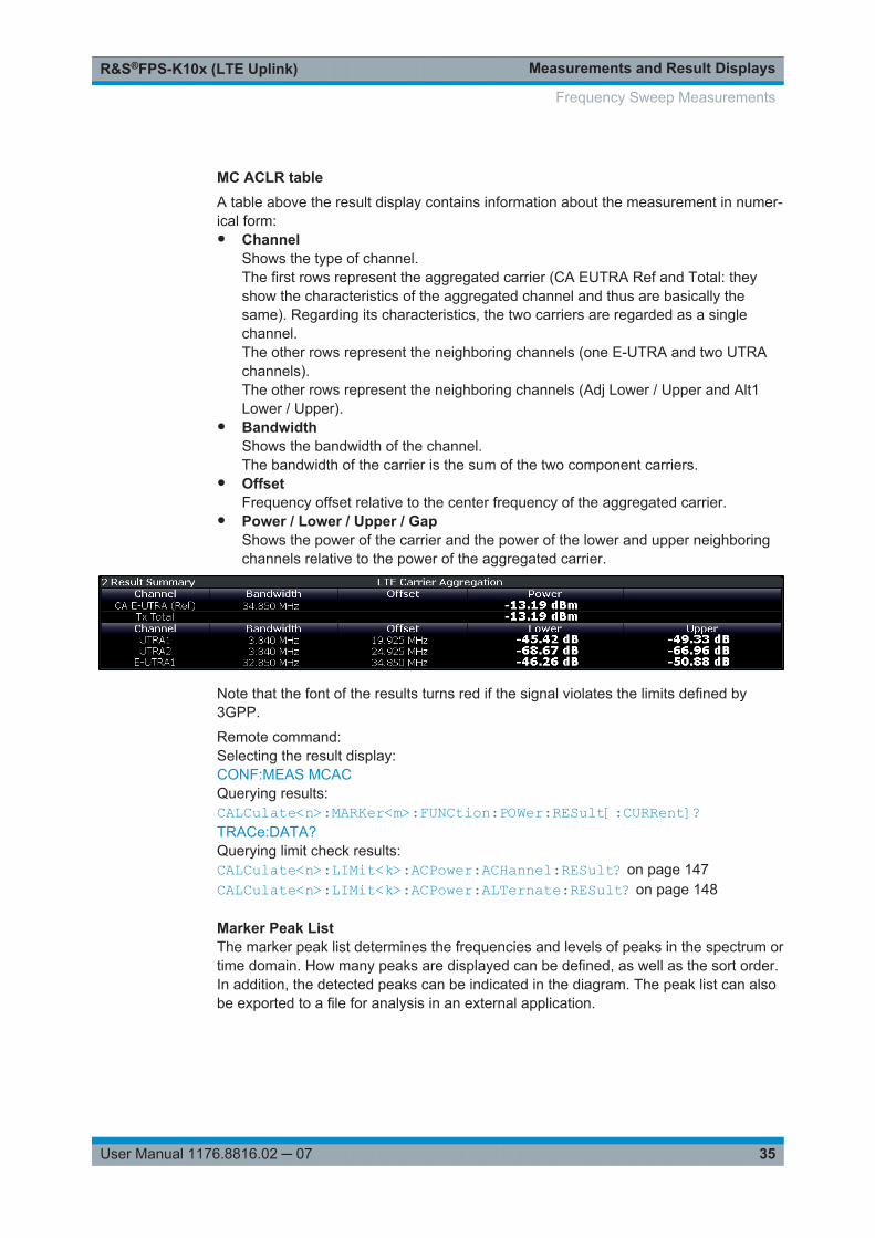
MC ACLR tableA table above the result display contains information about the measurement in numer-ical form:● Channel
Shows the type of channel.The first rows represent the aggregated carrier (CA EUTRA Ref and Total: theyshow the characteristics of the aggregated channel and thus are basically thesame). Regarding its characteristics, the two carriers are regarded as a singlechannel.The other rows represent the neighboring channels (one E-UTRA and two UTRAchannels).The other rows represent the neighboring channels (Adj Lower / Upper and Alt1Lower / Upper).
● BandwidthShows the bandwidth of the channel.The bandwidth of the carrier is the sum of the two component carriers.
● OffsetFrequency offset relative to the center frequency of the aggregated carrier.
● Power / Lower / Upper / GapShows the power of the carrier and the power of the lower and upper neighboringchannels relative to the power of the aggregated carrier.
Note that the font of the results turns red if the signal violates the limits defined by3GPP.
Remote command: Selecting the result display:CONF:MEAS MCACQuerying results:CALCulate<n>:MARKer<m>:FUNCtion:POWer:RESult[:CURRent]?TRACe:DATA?Querying limit check results:CALCulate<n>:LIMit<k>:ACPower:ACHannel:RESult? on page 147CALCulate<n>:LIMit<k>:ACPower:ALTernate:RESult? on page 148
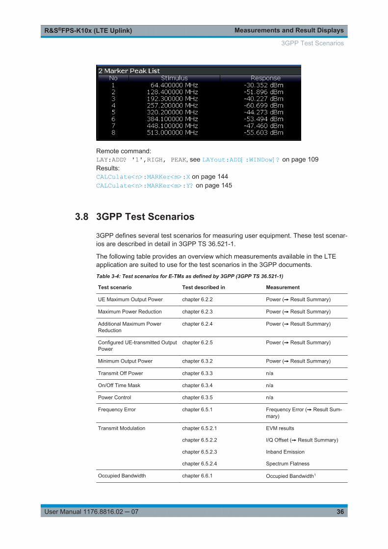
Marker Peak ListThe marker peak list determines the frequencies and levels of peaks in the spectrum ortime domain. How many peaks are displayed can be defined, as well as the sort order.In addition, the detected peaks can be indicated in the diagram. The peak list can alsobe exported to a file for analysis in an external application.
Frequency Sweep Measurements
Measurements and Result DisplaysR&S®FPS-K10x (LTE Uplink)
36User Manual 1176.8816.02 ─ 07
Remote command: LAY:ADD? '1',RIGH, PEAK, see LAYout:ADD[:WINDow]? on page 109Results:CALCulate<n>:MARKer<m>:X on page 144CALCulate<n>:MARKer<m>:Y? on page 145
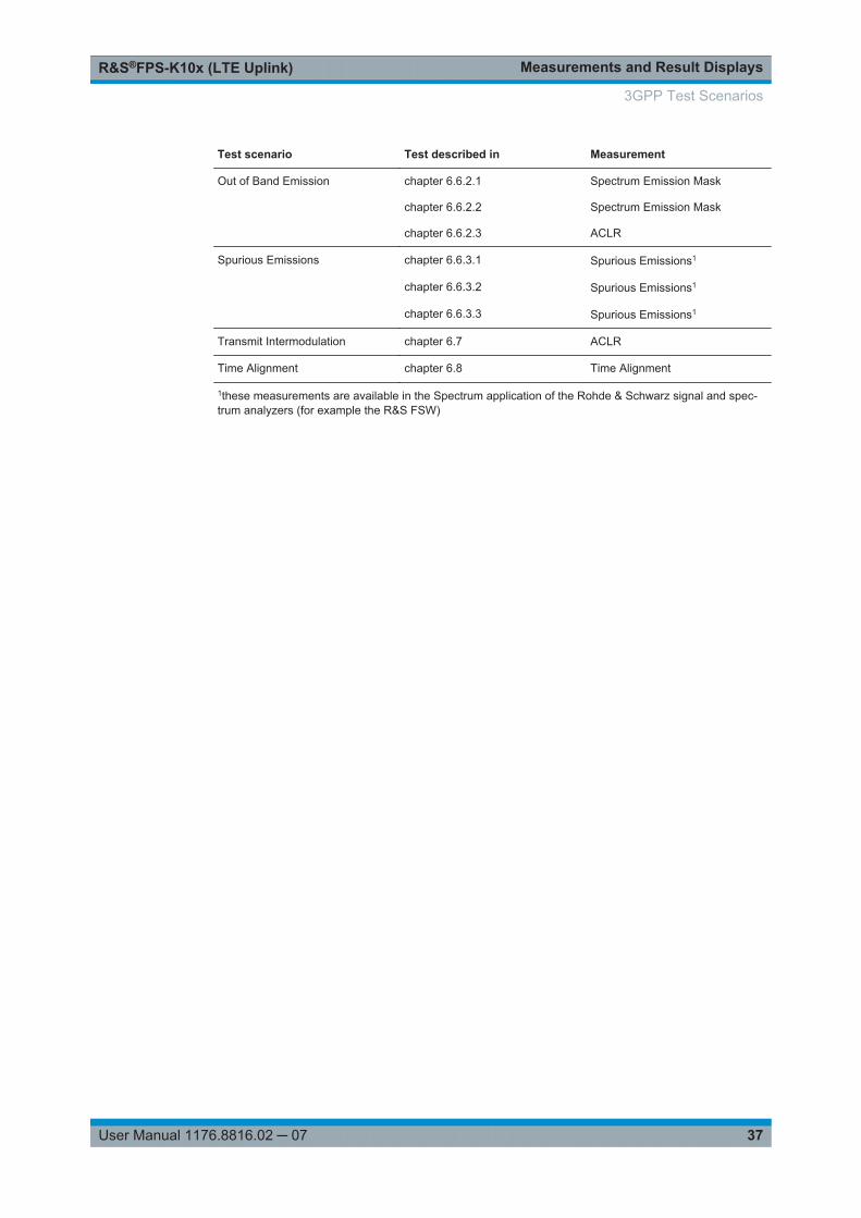
3.8 3GPP Test Scenarios
3GPP defines several test scenarios for measuring user equipment. These test scenar-ios are described in detail in 3GPP TS 36.521-1.
The following table provides an overview which measurements available in the LTEapplication are suited to use for the test scenarios in the 3GPP documents.
Table 3-4: Test scenarios for E-TMs as defined by 3GPP (3GPP TS 36.521-1)
Test scenario Test described in Measurement
UE Maximum Output Power chapter 6.2.2 Power (➙ Result Summary)
Maximum Power Reduction chapter 6.2.3 Power (➙ Result Summary)
Additional Maximum PowerReduction
chapter 6.2.4 Power (➙ Result Summary)
Configured UE-transmitted OutputPower
chapter 6.2.5 Power (➙ Result Summary)
Minimum Output Power chapter 6.3.2 Power (➙ Result Summary)
Transmit Off Power chapter 6.3.3 n/a
On/Off Time Mask chapter 6.3.4 n/a
Power Control chapter 6.3.5 n/a
Frequency Error chapter 6.5.1 Frequency Error (➙ Result Sum-mary)
Transmit Modulation chapter 6.5.2.1 EVM results
chapter 6.5.2.2 I/Q Offset (➙ Result Summary)
chapter 6.5.2.3 Inband Emission
chapter 6.5.2.4 Spectrum Flatness
Occupied Bandwidth chapter 6.6.1 Occupied Bandwidth1
3GPP Test Scenarios
Measurements and Result DisplaysR&S®FPS-K10x (LTE Uplink)
37User Manual 1176.8816.02 ─ 07
Test scenario Test described in Measurement
Out of Band Emission chapter 6.6.2.1 Spectrum Emission Mask
chapter 6.6.2.2 Spectrum Emission Mask
chapter 6.6.2.3 ACLR
Spurious Emissions chapter 6.6.3.1 Spurious Emissions1
chapter 6.6.3.2 Spurious Emissions1
chapter 6.6.3.3 Spurious Emissions1
Transmit Intermodulation chapter 6.7 ACLR
Time Alignment chapter 6.8 Time Alignment
1these measurements are available in the Spectrum application of the Rohde & Schwarz signal and spec-trum analyzers (for example the R&S FSW)
3GPP Test Scenarios
Measurement BasicsR&S®FPS-K10x (LTE Uplink)
38User Manual 1176.8816.02 ─ 07
4 Measurement Basics● Symbols and Variables........................................................................................... 38● Overview................................................................................................................. 39● The LTE Uplink Analysis Measurement Application............................................... 39● Performing Time Alignment Measurements............................................................43● SRS EVM Calculation............................................................................................. 44
4.1 Symbols and Variables
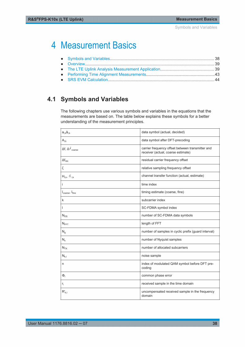
The following chapters use various symbols and variables in the equations that themeasurements are based on. The table below explains these symbols for a betterunderstanding of the measurement principles.
al,kâl,k data symbol (actual, decided)
Al,k data symbol after DFT-precoding
Δf, Δ coarse carrier frequency offset between transmitter andreceiver (actual, coarse estimate)
Δfres residual carrier frequency offset
ζ relative sampling frequency offset
Hl,k, l,k channel transfer function (actual, estimate)
i time index
îcoarse, îfine timing estimate (coarse, fine)
k subcarrier index
l SC-FDMA symbol index
NDS number of SC-FDMA data symbols
NFFT length of FFT
Ng number of samples in cyclic prefix (guard interval)
Ns number of Nyquist samples
NTX number of allocated subcarriers
Nk,l noise sample
n index of modulated QAM symbol before DFT pre-coding
Φl common phase error
ri received sample in the time domain
R'k,l uncompensated received sample in the frequencydomain
Symbols and Variables
Measurement BasicsR&S®FPS-K10x (LTE Uplink)
39User Manual 1176.8816.02 ─ 07
rn,l equalized received symbols of measurement pathafter IDFT
T duration of the useful part of an SC-FDMA symbol
Tg duration of the guard interval
Ts total duration of SC-FDMA symbol
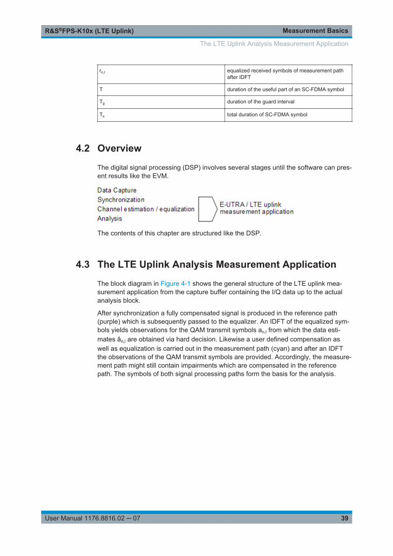
4.2 Overview
The digital signal processing (DSP) involves several stages until the software can pres-ent results like the EVM.
The contents of this chapter are structured like the DSP.
4.3 The LTE Uplink Analysis Measurement Application
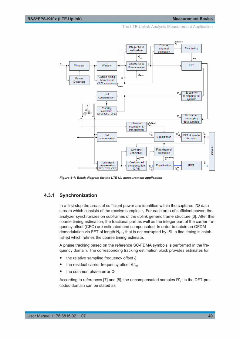
The block diagram in Figure 4-1 shows the general structure of the LTE uplink mea-surement application from the capture buffer containing the I/Q data up to the actualanalysis block.
After synchronization a fully compensated signal is produced in the reference path(purple) which is subsequently passed to the equalizer. An IDFT of the equalized sym-bols yields observations for the QAM transmit symbols an.l from which the data esti-mates ân,l are obtained via hard decision. Likewise a user defined compensation aswell as equalization is carried out in the measurement path (cyan) and after an IDFTthe observations of the QAM transmit symbols are provided. Accordingly, the measure-ment path might still contain impairments which are compensated in the referencepath. The symbols of both signal processing paths form the basis for the analysis.
The LTE Uplink Analysis Measurement Application
Measurement BasicsR&S®FPS-K10x (LTE Uplink)
40User Manual 1176.8816.02 ─ 07
Figure 4-1: Block diagram for the LTE UL measurement application
4.3.1 Synchronization
In a first step the areas of sufficient power are identified within the captured I/Q datastream which consists of the receive samples ri. For each area of sufficient power, theanalyzer synchronizes on subframes of the uplink generic frame structure [3]. After thiscoarse timing estimation, the fractional part as well as the integer part of the carrier fre-quency offset (CFO) are estimated and compensated. In order to obtain an OFDMdemodulation via FFT of length NFFT that is not corrupted by ISI, a fine timing is estab-lished which refines the coarse timing estimate.
A phase tracking based on the reference SC-FDMA symbols is performed in the fre-quency domain. The corresponding tracking estimation block provides estimates for
● the relative sampling frequency offset ζ● the residual carrier frequency offset Δfres
● the common phase error Φl
According to references [7] and [8], the uncompensated samples R'k,l in the DFT-pre-coded domain can be stated as
The LTE Uplink Analysis Measurement Application
Measurement BasicsR&S®FPS-K10x (LTE Uplink)
41User Manual 1176.8816.02 ─ 07
lklTfNNjlkNNjj
lklklk NeeeHARCFOres
resFFTS
SFO
FFTS
CPE
l,
22,,
',
.
Equation 4-1:
with
● the DFT precoded data symbol Ak,l on subcarrier k at SC-FDMA symbol l,
● the channel transfer function Hk,l,
● the number of Nyquist samples NS within the total duration TS,
● the duration of the useful part of the SC-FDMA symbol T=TS-Tg
● the independent and Gaussian distributed noise sample Nk,l
Within one SC-FDMA symbol, both the CPE and the residual CFO cause the samephase rotation for each subcarrier, while the rotation due to the SFO depends linearlyon the subcarrier index. A linear phase increase in symbol direction can be observedfor the residual CFO as well as for the SFO.
The results of the tracking estimation block are used to compensate the samples R'k,l
completely in the reference path and according to the user settings in the measure-ment path. Thus the signal impairments that are of interest to the user are left uncom-pensated in the measurement path.
After having decoded the data symbols in the reference path, an additional data-aidedphase tracking can be utilized to refine the common phase error estimation.
4.3.2 Analysis
The analysis block of the EUTRA/LTE uplink measurement application allows to com-pute a variety of measurement variables.
EVM
The most important variable is the error vector magnitude which is defined as
2,
,,,
ˆ~
ln
lnlnkl
aE
arEVM
Equation 4-2:
for QAM symbol n before precoding and SC-FDMA symbol l. Since the normalizedaverage power of all possible constellations is 1, the equation can be simplified to
lnlnln arEVM ,,, ˆ~
Equation 4-3:
The average EVM of all data subcarriers is then
The LTE Uplink Analysis Measurement Application
Measurement BasicsR&S®FPS-K10x (LTE Uplink)
42User Manual 1176.8816.02 ─ 07
1
0
1
0
2,
1 LB TXN
l
N
nln
TXDSdata EVM
NNEVM
Equation 4-4:
for NDS SC-FDMA data symbols and the NTX allocated subcarriers.
I/Q imbalance
The I/Q imbalance contained in the continuous received signal r(t) can be written as
tsjQtsItr
Equation 4-5:
where s(t) is the transmit signal and I and Q are the weighting factors describing theI/Q imbalance. We define that I:=1 and Q:=1+ΔQ.
The I/Q imbalance estimation makes it possible to evaluate the
|1|balancegain modulator Q
Equation 4-6:
and the
}1arg{mismatch quadrature Q
Equation 4-7:
based on the complex-valued estimate .
Basic in-band emissions measurement
The in-band emissions are a measure of the interference falling into the non-allocatedresources blocks.
The relative in-band emissions are given by
S
RB
Tt
Nc
cRBS
RBabsoluteRBrelative
ftYNT
EmissionsEmissions 1122,1
Equation 4-8:
where TS is a set |TS| of SC-FDMA symbols with the considered modulation schemebeing active within the measurement period, ΔRB is the starting frequency offsetbetween the allocated RB and the measured non-allocated RB (e.g. ΔRB=1 or ΔRB=-1for the first adjacent RB), c is the lower edge of the allocated BW, and Y(t,f) is the fre-quency domain signal evaluated for in-band emissions. NRB is the number of allocatedRBs .
The basic in-band emissions measurement interval is defined over one slot in the timedomain.
The LTE Uplink Analysis Measurement Application

Measurement BasicsR&S®FPS-K10x (LTE Uplink)
43User Manual 1176.8816.02 ─ 07
Other measurement variables
Without going into detail, the EUTRA/LTE uplink measurement application additionallyprovides the following results:
● Total power● Constellation diagram● Group delay● I/Q offset● Crest factor● Spectral flatness
4.4 Performing Time Alignment Measurements
The measurement application allows you to perform time alignment measurementsbetween different antennas.
The measurement supports setups of up to two Tx antennas.
The result of the measurement is the time alignment error. The time alignment error isthe time offset between a reference antenna (for example antenna 1) and anotherantenna.
The time alignment error results are summarized in the corresponding result display.
A schematic description of the results is provided in Figure 4-2.
Tx Antenna 1 (Reference)
Time
Tx Antenna 2
Time
Time Alignment Error Δ2,1LTE
Fra
me
Sta
rt In
dica
tor
Figure 4-2: Time Alignment Error (2 Tx antennas)
Test setup
Successful Time Alignment measurements require a correct test setup.
A typical test setup is shown in Figure 4-3.
Performing Time Alignment Measurements
Measurement BasicsR&S®FPS-K10x (LTE Uplink)
44User Manual 1176.8816.02 ─ 07
DUTTx Ant 1
Tx Ant 2+ FSx
Figure 4-3: Hardware setup
For best measurement result accuracy, it is recommended to use cables of the samelength and identical combiners as adders.
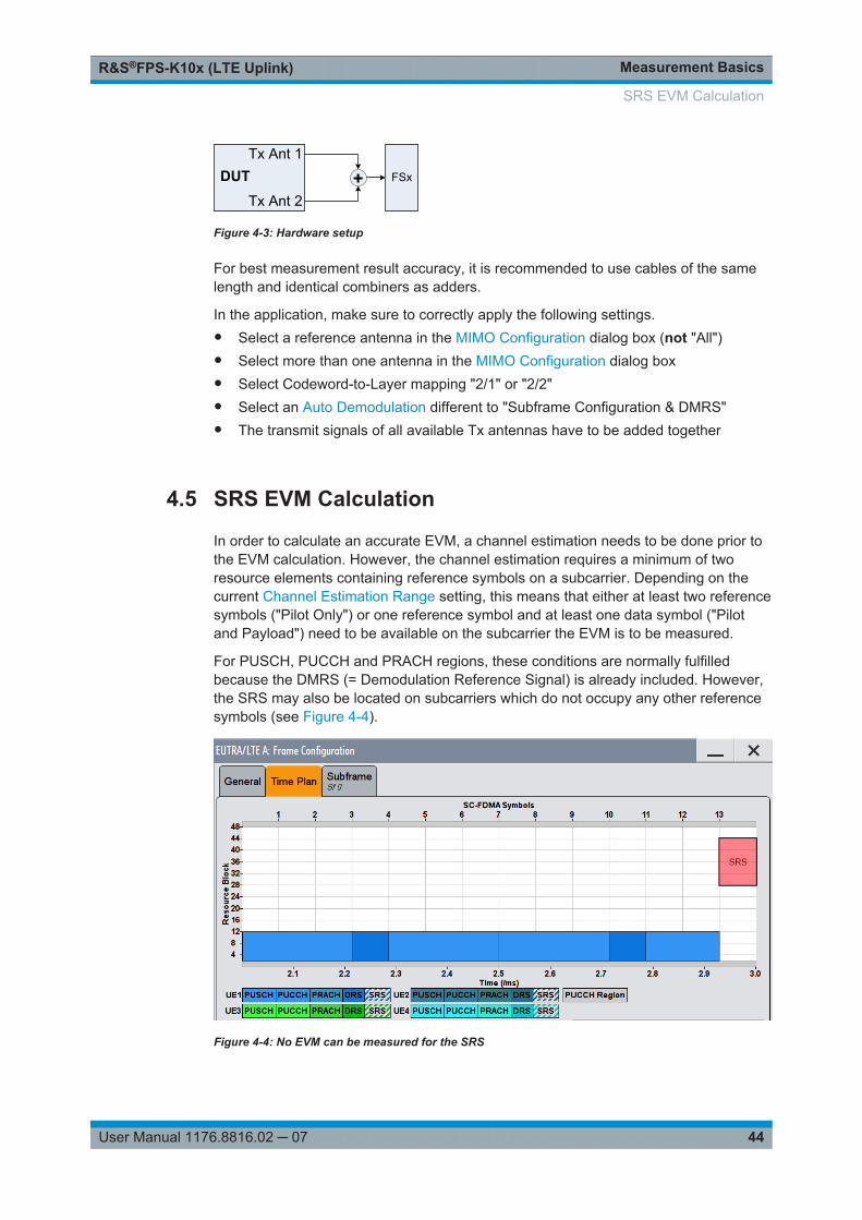
In the application, make sure to correctly apply the following settings.● Select a reference antenna in the MIMO Configuration dialog box (not "All")● Select more than one antenna in the MIMO Configuration dialog box● Select Codeword-to-Layer mapping "2/1" or "2/2"● Select an Auto Demodulation different to "Subframe Configuration & DMRS"● The transmit signals of all available Tx antennas have to be added together
4.5 SRS EVM Calculation
In order to calculate an accurate EVM, a channel estimation needs to be done prior tothe EVM calculation. However, the channel estimation requires a minimum of tworesource elements containing reference symbols on a subcarrier. Depending on thecurrent Channel Estimation Range setting, this means that either at least two referencesymbols ("Pilot Only") or one reference symbol and at least one data symbol ("Pilotand Payload") need to be available on the subcarrier the EVM is to be measured.
For PUSCH, PUCCH and PRACH regions, these conditions are normally fulfilledbecause the DMRS (= Demodulation Reference Signal) is already included. However,the SRS may also be located on subcarriers which do not occupy any other referencesymbols (see Figure 4-4).
Figure 4-4: No EVM can be measured for the SRS
SRS EVM Calculation
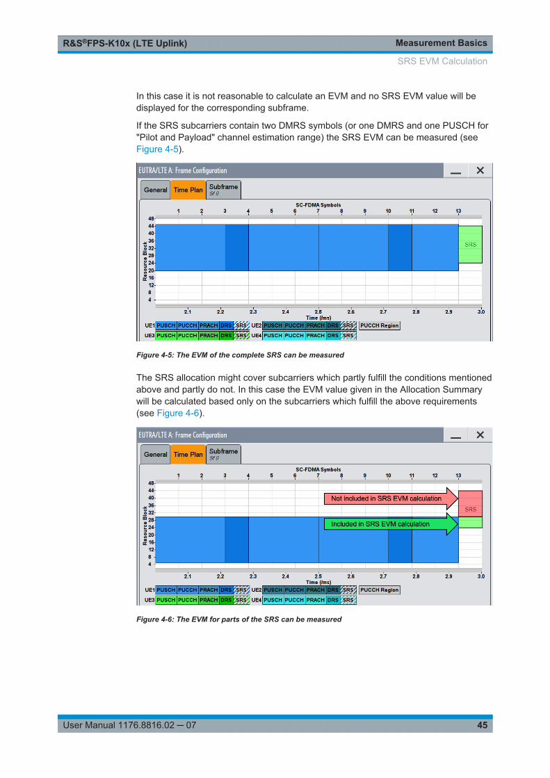
Measurement BasicsR&S®FPS-K10x (LTE Uplink)
45User Manual 1176.8816.02 ─ 07
In this case it is not reasonable to calculate an EVM and no SRS EVM value will bedisplayed for the corresponding subframe.
If the SRS subcarriers contain two DMRS symbols (or one DMRS and one PUSCH for"Pilot and Payload" channel estimation range) the SRS EVM can be measured (seeFigure 4-5).
Figure 4-5: The EVM of the complete SRS can be measured
The SRS allocation might cover subcarriers which partly fulfill the conditions mentionedabove and partly do not. In this case the EVM value given in the Allocation Summarywill be calculated based only on the subcarriers which fulfill the above requirements(see Figure 4-6).
Figure 4-6: The EVM for parts of the SRS can be measured
SRS EVM Calculation
ConfigurationR&S®FPS-K10x (LTE Uplink)
46User Manual 1176.8816.02 ─ 07
5 ConfigurationLTE measurements require a special application on the R&S FPS.
When you start the LTE application, the R&S FPS starts to measure the input signalwith the default configuration or the configuration of the last measurement (when youhaven't performed a preset since then).
Automatic refresh of preview and visualization in dialog boxes after configura-tion changesThe R&S FPS supports you in finding the correct measurement settings quickly andeasily - after each change in settings in dialog boxes, the preview and visualizationareas are updated immediately and automatically to reflect the changes. Thus, you cansee if the setting is appropriate or not before accepting the changes.
Unavailable menusNote that the SPAN, BW, TRACE, LINES and MKR FUNC menus have no function inthe LTE application.
● Configuration Overview...........................................................................................46● Configuring I/Q Measurements............................................................................... 48● Configuring Time Alignment Error Measurements..................................................86● Configuring Frequency Sweep Measurements.......................................................87
5.1 Configuration Overview
Throughout the measurement channel configuration, an overview of the most importantcurrently defined settings is provided in the "Overview". The "Overview" is displayedwhen you select the "Overview" icon, which is available at the bottom of all softkeymenus.
Configuration Overview
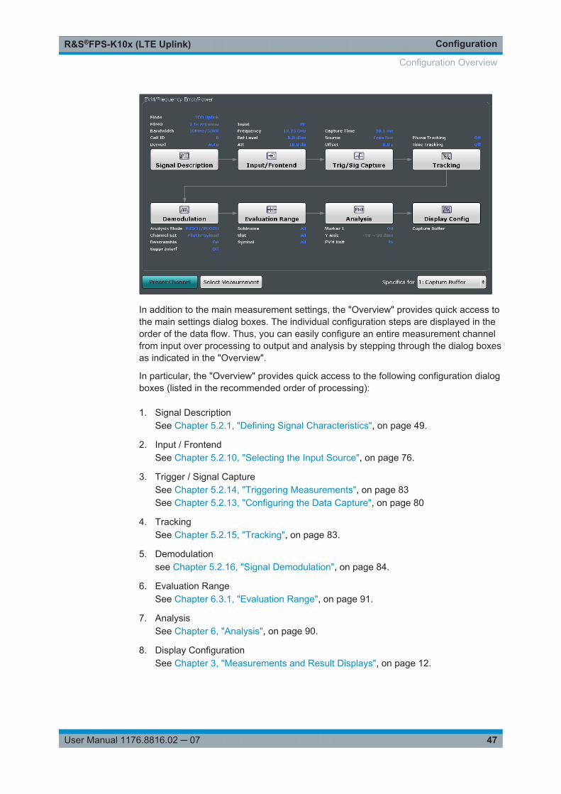
ConfigurationR&S®FPS-K10x (LTE Uplink)
47User Manual 1176.8816.02 ─ 07
In addition to the main measurement settings, the "Overview" provides quick access tothe main settings dialog boxes. The individual configuration steps are displayed in theorder of the data flow. Thus, you can easily configure an entire measurement channelfrom input over processing to output and analysis by stepping through the dialog boxesas indicated in the "Overview".
In particular, the "Overview" provides quick access to the following configuration dialogboxes (listed in the recommended order of processing):
1. Signal DescriptionSee Chapter 5.2.1, "Defining Signal Characteristics", on page 49.
2. Input / FrontendSee Chapter 5.2.10, "Selecting the Input Source", on page 76.
3. Trigger / Signal CaptureSee Chapter 5.2.14, "Triggering Measurements", on page 83See Chapter 5.2.13, "Configuring the Data Capture", on page 80
4. TrackingSee Chapter 5.2.15, "Tracking", on page 83.
5. Demodulationsee Chapter 5.2.16, "Signal Demodulation", on page 84.
6. Evaluation RangeSee Chapter 6.3.1, "Evaluation Range", on page 91.
7. AnalysisSee Chapter 6, "Analysis", on page 90.
8. Display ConfigurationSee Chapter 3, "Measurements and Result Displays", on page 12.
Configuration Overview
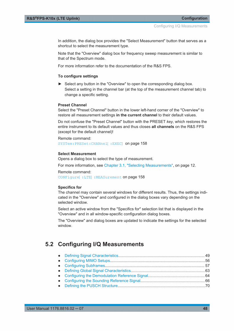
ConfigurationR&S®FPS-K10x (LTE Uplink)
48User Manual 1176.8816.02 ─ 07
In addition, the dialog box provides the "Select Measurement" button that serves as ashortcut to select the measurement type.
Note that the "Overview" dialog box for frequency sweep measurement is similar tothat of the Spectrum mode.
For more information refer to the documentation of the R&S FPS.
To configure settings
► Select any button in the "Overview" to open the corresponding dialog box.Select a setting in the channel bar (at the top of the measurement channel tab) tochange a specific setting.
Preset ChannelSelect the "Preset Channel" button in the lower left-hand corner of the "Overview" torestore all measurement settings in the current channel to their default values.
Do not confuse the "Preset Channel" button with the PRESET key, which restores theentire instrument to its default values and thus closes all channels on the R&S FPS(except for the default channel)!
Remote command: SYSTem:PRESet:CHANnel[:EXEC] on page 158
Select MeasurementOpens a dialog box to select the type of measurement.
For more information, see Chapter 3.1, "Selecting Measurements", on page 12.
Remote command: CONFigure[:LTE]:MEASurement on page 158
Specifics forThe channel may contain several windows for different results. Thus, the settings indi-cated in the "Overview" and configured in the dialog boxes vary depending on theselected window.
Select an active window from the "Specifics for" selection list that is displayed in the"Overview" and in all window-specific configuration dialog boxes.
The "Overview" and dialog boxes are updated to indicate the settings for the selectedwindow.
5.2 Configuring I/Q Measurements
● Defining Signal Characteristics............................................................................... 49● Configuring MIMO Setups.......................................................................................56● Configuring Subframes........................................................................................... 57● Defining Global Signal Characteristics....................................................................63● Configuring the Demodulation Reference Signal....................................................64● Configuring the Sounding Reference Signal...........................................................66● Defining the PUSCH Structure................................................................................70
Configuring I/Q Measurements
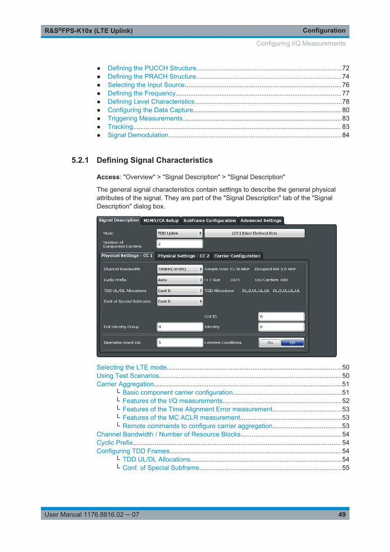
ConfigurationR&S®FPS-K10x (LTE Uplink)
49User Manual 1176.8816.02 ─ 07
● Defining the PUCCH Structure................................................................................72● Defining the PRACH Structure................................................................................74● Selecting the Input Source......................................................................................76● Defining the Frequency...........................................................................................77● Defining Level Characteristics.................................................................................78● Configuring the Data Capture................................................................................. 80● Triggering Measurements....................................................................................... 83● Tracking.................................................................................................................. 83● Signal Demodulation...............................................................................................84
5.2.1 Defining Signal Characteristics
Access: "Overview" > "Signal Description" > "Signal Description"
The general signal characteristics contain settings to describe the general physicalattributes of the signal. They are part of the "Signal Description" tab of the "SignalDescription" dialog box.
Selecting the LTE mode................................................................................................50Using Test Scenarios.................................................................................................... 50Carrier Aggregation.......................................................................................................51
└ Basic component carrier configuration............................................................51└ Features of the I/Q measurements................................................................. 52└ Features of the Time Alignment Error measurement......................................53└ Features of the MC ACLR measurement........................................................53└ Remote commands to configure carrier aggregation......................................53
Channel Bandwidth / Number of Resource Blocks....................................................... 54Cyclic Prefix.................................................................................................................. 54Configuring TDD Frames.............................................................................................. 54
└ TDD UL/DL Allocations...................................................................................54└ Conf. of Special Subframe..............................................................................55
Configuring I/Q Measurements
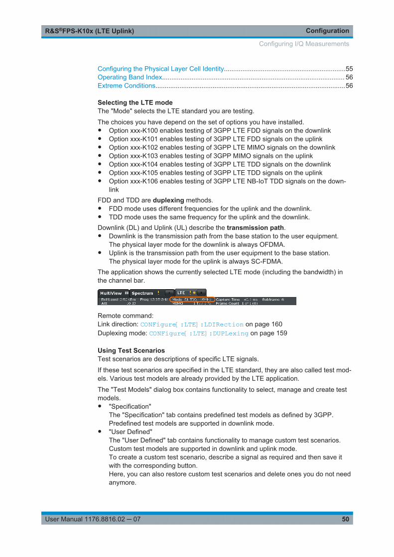
ConfigurationR&S®FPS-K10x (LTE Uplink)
50User Manual 1176.8816.02 ─ 07
Configuring the Physical Layer Cell Identity..................................................................55Operating Band Index................................................................................................... 56Extreme Conditions.......................................................................................................56
Selecting the LTE modeThe "Mode" selects the LTE standard you are testing.
The choices you have depend on the set of options you have installed.● Option xxx-K100 enables testing of 3GPP LTE FDD signals on the downlink● Option xxx-K101 enables testing of 3GPP LTE FDD signals on the uplink● Option xxx-K102 enables testing of 3GPP LTE MIMO signals on the downlink● Option xxx-K103 enables testing of 3GPP MIMO signals on the uplink● Option xxx-K104 enables testing of 3GPP LTE TDD signals on the downlink● Option xxx-K105 enables testing of 3GPP LTE TDD signals on the uplink● Option xxx-K106 enables testing of 3GPP LTE NB-IoT TDD signals on the down-
linkFDD and TDD are duplexing methods.● FDD mode uses different frequencies for the uplink and the downlink.● TDD mode uses the same frequency for the uplink and the downlink.Downlink (DL) and Uplink (UL) describe the transmission path.● Downlink is the transmission path from the base station to the user equipment.
The physical layer mode for the downlink is always OFDMA.● Uplink is the transmission path from the user equipment to the base station.
The physical layer mode for the uplink is always SC-FDMA.The application shows the currently selected LTE mode (including the bandwidth) inthe channel bar.
Remote command: Link direction: CONFigure[:LTE]:LDIRection on page 160Duplexing mode: CONFigure[:LTE]:DUPLexing on page 159
Using Test ScenariosTest scenarios are descriptions of specific LTE signals.
If these test scenarios are specified in the LTE standard, they are also called test mod-els. Various test models are already provided by the LTE application.
The "Test Models" dialog box contains functionality to select, manage and create testmodels.● "Specification"
The "Specification" tab contains predefined test models as defined by 3GPP.Predefined test models are supported in downlink mode.
● "User Defined"The "User Defined" tab contains functionality to manage custom test scenarios.Custom test models are supported in downlink and uplink mode.To create a custom test scenario, describe a signal as required and then save itwith the corresponding button.Here, you can also restore custom test scenarios and delete ones you do not needanymore.
Configuring I/Q Measurements
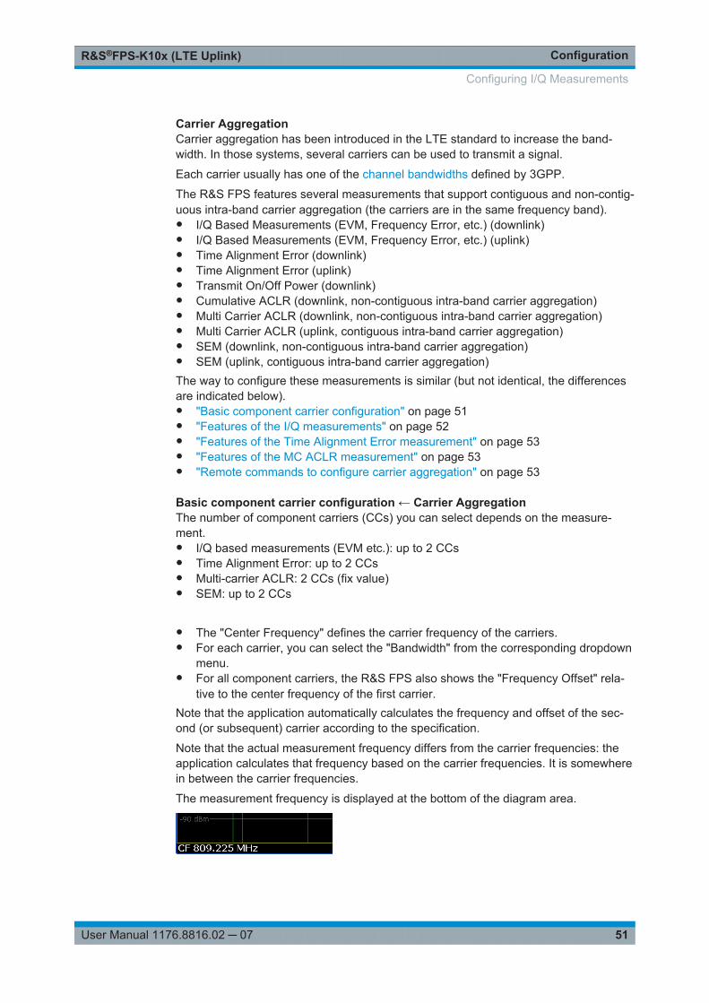
ConfigurationR&S®FPS-K10x (LTE Uplink)
51User Manual 1176.8816.02 ─ 07
Carrier AggregationCarrier aggregation has been introduced in the LTE standard to increase the band-width. In those systems, several carriers can be used to transmit a signal.
Each carrier usually has one of the channel bandwidths defined by 3GPP.
The R&S FPS features several measurements that support contiguous and non-contig-uous intra-band carrier aggregation (the carriers are in the same frequency band).● I/Q Based Measurements (EVM, Frequency Error, etc.) (downlink)● I/Q Based Measurements (EVM, Frequency Error, etc.) (uplink)● Time Alignment Error (downlink)● Time Alignment Error (uplink)● Transmit On/Off Power (downlink)● Cumulative ACLR (downlink, non-contiguous intra-band carrier aggregation)● Multi Carrier ACLR (downlink, non-contiguous intra-band carrier aggregation)● Multi Carrier ACLR (uplink, contiguous intra-band carrier aggregation)● SEM (downlink, non-contiguous intra-band carrier aggregation)● SEM (uplink, contiguous intra-band carrier aggregation)The way to configure these measurements is similar (but not identical, the differencesare indicated below).● "Basic component carrier configuration" on page 51● "Features of the I/Q measurements" on page 52● "Features of the Time Alignment Error measurement" on page 53● "Features of the MC ACLR measurement" on page 53● "Remote commands to configure carrier aggregation" on page 53
Basic component carrier configuration ← Carrier AggregationThe number of component carriers (CCs) you can select depends on the measure-ment.● I/Q based measurements (EVM etc.): up to 2 CCs● Time Alignment Error: up to 2 CCs● Multi-carrier ACLR: 2 CCs (fix value)● SEM: up to 2 CCs ● The "Center Frequency" defines the carrier frequency of the carriers.● For each carrier, you can select the "Bandwidth" from the corresponding dropdown
menu.● For all component carriers, the R&S FPS also shows the "Frequency Offset" rela-
tive to the center frequency of the first carrier.Note that the application automatically calculates the frequency and offset of the sec-ond (or subsequent) carrier according to the specification.
Note that the actual measurement frequency differs from the carrier frequencies: theapplication calculates that frequency based on the carrier frequencies. It is somewherein between the carrier frequencies.
The measurement frequency is displayed at the bottom of the diagram area.
Configuring I/Q Measurements
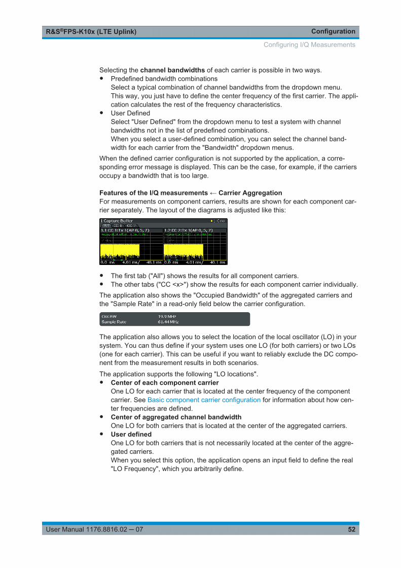
ConfigurationR&S®FPS-K10x (LTE Uplink)
52User Manual 1176.8816.02 ─ 07
Selecting the channel bandwidths of each carrier is possible in two ways.● Predefined bandwidth combinations
Select a typical combination of channel bandwidths from the dropdown menu.This way, you just have to define the center frequency of the first carrier. The appli-cation calculates the rest of the frequency characteristics.
● User DefinedSelect "User Defined" from the dropdown menu to test a system with channelbandwidths not in the list of predefined combinations.When you select a user-defined combination, you can select the channel band-width for each carrier from the "Bandwidth" dropdown menus.
When the defined carrier configuration is not supported by the application, a corre-sponding error message is displayed. This can be the case, for example, if the carriersoccupy a bandwidth that is too large.
Features of the I/Q measurements ← Carrier AggregationFor measurements on component carriers, results are shown for each component car-rier separately. The layout of the diagrams is adjusted like this:
● The first tab ("All") shows the results for all component carriers.● The other tabs ("CC <x>") show the results for each component carrier individually.The application also shows the "Occupied Bandwidth" of the aggregated carriers andthe "Sample Rate" in a read-only field below the carrier configuration.
The application also allows you to select the location of the local oscillator (LO) in yoursystem. You can thus define if your system uses one LO (for both carriers) or two LOs(one for each carrier). This can be useful if you want to reliably exclude the DC compo-nent from the measurement results in both scenarios.
The application supports the following "LO locations".● Center of each component carrier
One LO for each carrier that is located at the center frequency of the componentcarrier. See Basic component carrier configuration for information about how cen-ter frequencies are defined.
● Center of aggregated channel bandwidthOne LO for both carriers that is located at the center of the aggregated carriers.
● User definedOne LO for both carriers that is not necessarily located at the center of the aggre-gated carriers.When you select this option, the application opens an input field to define the real"LO Frequency", which you arbitrarily define.
Configuring I/Q Measurements

ConfigurationR&S®FPS-K10x (LTE Uplink)
53User Manual 1176.8816.02 ─ 07
Features of the Time Alignment Error measurement ← Carrier AggregationNote that the TAE measurements are possible on one R&S FPS only. Therefore thenumber of devices to measure is always "1".
You can configure additional signal characteristics of the first and second carrier in the"CC1" and "CC2" tabs.
More information
In case you are testing a MIMO DUT, you can also select the number of antennas theDUT supports. When you select "1 Tx Antenna", the application measures the timingdifference between two SISO carriers, when you select more than one antenna, itmeasures the timing difference between the antennas. In that case, you can select thereference antenna from the dropdown menu in the Time Alignment Error result display.
Note that the application shows measurement results for the second component carriereven if only one antenna of the second component carrier is attached (i.e. no combineris used).
Features of the MC ACLR measurement ← Carrier AggregationThe diagram at the bottom of the dialog box represents the current configuration.When you change the bandwidth of a carrier (represented by blue bars), the applica-tion adjusts the bandwidth of the carriers in the diagram accordingly.
The characteristics of the neighboring channels in the MC ACLR measurement aredefined in 3GPP 36.251 (represented by green bars).
Remote commands to configure carrier aggregation ← Carrier Aggregation Remote command: Number of carriers: CONFigure[:LTE]:NOCC on page 202Carrier frequency: [SENSe:]FREQuency:CENTer[:CC<cc>] on page 188Measurement frequency: SENSe:FREQuency:CENTer?Offset: [SENSe]:FREQuency:CENTer[:CC<cc>]:OFFSet on page 188Channel bandwidth: CONFigure[:LTE]:UL:CABW on page 202Channel bandwidth: CONFigure[:LTE]:UL[:CC<cc>]:BW on page 160Number of devices: CONFigure[:LTE]:NDEV on page 203LO location: [SENSe][:LTE]:UL:DEMod:LOLocation on page 165LO frequency: [SENSe][:LTE]:UL:DEMod:LOFRequency on page 165
Configuring I/Q Measurements
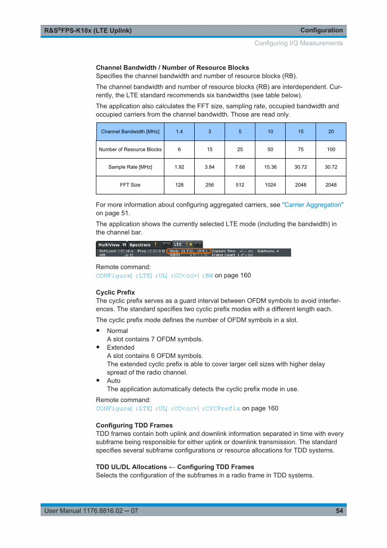
ConfigurationR&S®FPS-K10x (LTE Uplink)
54User Manual 1176.8816.02 ─ 07
Channel Bandwidth / Number of Resource BlocksSpecifies the channel bandwidth and number of resource blocks (RB).
The channel bandwidth and number of resource blocks (RB) are interdependent. Cur-rently, the LTE standard recommends six bandwidths (see table below).
The application also calculates the FFT size, sampling rate, occupied bandwidth andoccupied carriers from the channel bandwidth. Those are read only.
Channel Bandwidth [MHz] 1.4 20151053
Number of Resource Blocks 6 10075502515
Sample Rate [MHz] 1.92 30.7230.7215.367.683.84
FFT Size 128 204820481024512256
For more information about configuring aggregated carriers, see "Carrier Aggregation"on page 51.
The application shows the currently selected LTE mode (including the bandwidth) inthe channel bar.
Remote command: CONFigure[:LTE]:UL[:CC<cc>]:BW on page 160
Cyclic PrefixThe cyclic prefix serves as a guard interval between OFDM symbols to avoid interfer-ences. The standard specifies two cyclic prefix modes with a different length each.
The cyclic prefix mode defines the number of OFDM symbols in a slot.● Normal
A slot contains 7 OFDM symbols.● Extended
A slot contains 6 OFDM symbols.The extended cyclic prefix is able to cover larger cell sizes with higher delayspread of the radio channel.
● AutoThe application automatically detects the cyclic prefix mode in use.
Remote command: CONFigure[:LTE]:UL[:CC<cc>]:CYCPrefix on page 160
Configuring TDD FramesTDD frames contain both uplink and downlink information separated in time with everysubframe being responsible for either uplink or downlink transmission. The standardspecifies several subframe configurations or resource allocations for TDD systems.
TDD UL/DL Allocations ← Configuring TDD FramesSelects the configuration of the subframes in a radio frame in TDD systems.
Configuring I/Q Measurements
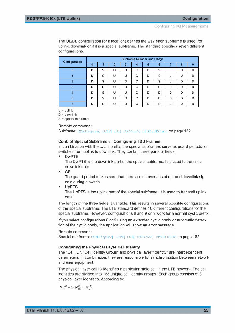
ConfigurationR&S®FPS-K10x (LTE Uplink)
55User Manual 1176.8816.02 ─ 07
The UL/DL configuration (or allocation) defines the way each subframe is used: foruplink, downlink or if it is a special subframe. The standard specifies seven differentconfigurations.
ConfigurationSubframe Number and Usage
0 987654321
0
1
2
3
4
5
6
D
D
D
D
D
D
D
S
S
S
S
S
S
S
U
U
U
U
U
U
U
U
U
D
U
U
D
U
U
D
D
U
D
D
U
D
D
D
D
D
D
D
S
S
S
D
D
D
S
U
U
U
D
D
D
U
U
U
D
D
D
D
U
U
D
D
D
D
D
D
U = uplinkD = downlinkS = special subframe
Remote command: Subframe: CONFigure[:LTE]:UL[:CC<cc>]:TDD:UDConf on page 162
Conf. of Special Subframe ← Configuring TDD FramesIn combination with the cyclic prefix, the special subframes serve as guard periods forswitches from uplink to downlink. They contain three parts or fields.● DwPTS
The DwPTS is the downlink part of the special subframe. It is used to transmitdownlink data.
● GPThe guard period makes sure that there are no overlaps of up- and downlink sig-nals during a switch.
● UpPTSThe UpPTS is the uplink part of the special subframe. It is used to transmit uplinkdata.
The length of the three fields is variable. This results in several possible configurationsof the special subframe. The LTE standard defines 10 different configurations for thespecial subframe. However, configurations 8 and 9 only work for a normal cyclic prefix.
If you select configurations 8 or 9 using an extended cyclic prefix or automatic detec-tion of the cyclic prefix, the application will show an error message.
Remote command: Special subframe: CONFigure[:LTE]:UL[:CC<cc>]:TDD:SPSC on page 162
Configuring the Physical Layer Cell IdentityThe "Cell ID", "Cell Identity Group" and physical layer "Identity" are interdependentparameters. In combination, they are responsible for synchronization between networkand user equipment.
The physical layer cell ID identifies a particular radio cell in the LTE network. The cellidentities are divided into 168 unique cell identity groups. Each group consists of 3physical layer identities. According to:
)2()1(3 IDIDcellID NNN
Configuring I/Q Measurements
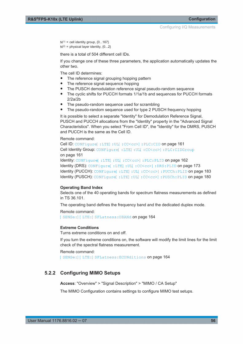
ConfigurationR&S®FPS-K10x (LTE Uplink)
56User Manual 1176.8816.02 ─ 07
N(1) = cell identity group, {0...167}N(2) = physical layer identity, {0...2}
there is a total of 504 different cell IDs.
If you change one of these three parameters, the application automatically updates theother two.
The cell ID determines:● The reference signal grouping hopping pattern● The reference signal sequence hopping● The PUSCH demodulation reference signal pseudo-random sequence● The cyclic shifts for PUCCH formats 1/1a/1b and sequences for PUCCH formats
2/2a/2b● The pseudo-random sequence used for scrambling● The pseudo-random sequence used for type 2 PUSCH frequency hoppingIt is possible to select a separate "Identity" for Demodulation Reference Signal,PUSCH and PUCCH allocations from the "Identity" property in the "Advanced SignalCharacteristics". When you select "From Cell ID", the "Identity" for the DMRS, PUSCHand PUCCH is the same as the Cell ID.
Remote command: Cell ID: CONFigure[:LTE]:UL[:CC<cc>]:PLC:CID on page 161Cell Identity Group: CONFigure[:LTE]:UL[:CC<cc>]:PLC:CIDGroupon page 161Identity: CONFigure[:LTE]:UL[:CC<cc>]:PLC:PLID on page 162Identity (DRS): CONFigure[:LTE]:UL[:CC<cc>]:DRS:PLID on page 173Identity (PUCCH): CONFigure[:LTE]:UL[:CC<cc>]:PUCCh:PLID on page 183Identity (PUSCH): CONFigure[:LTE]:UL[:CC<cc>]:PUSCh:PLID on page 180
Operating Band IndexSelects one of the 40 operating bands for spectrum flatness measurements as definedin TS 36.101.
The operating band defines the frequency band and the dedicated duplex mode.
Remote command: [SENSe:][LTE:]SFLatness:OBANd on page 164
Extreme ConditionsTurns extreme conditions on and off.
If you turn the extreme conditions on, the software will modify the limit lines for the limitcheck of the spectral flatness measurement.
Remote command: [SENSe:][LTE:]SFLatness:ECONditions on page 164
5.2.2 Configuring MIMO Setups
Access: "Overview" > "Signal Description" > "MIMO / CA Setup"
The MIMO Configuration contains settings to configure MIMO test setups.
Configuring I/Q Measurements
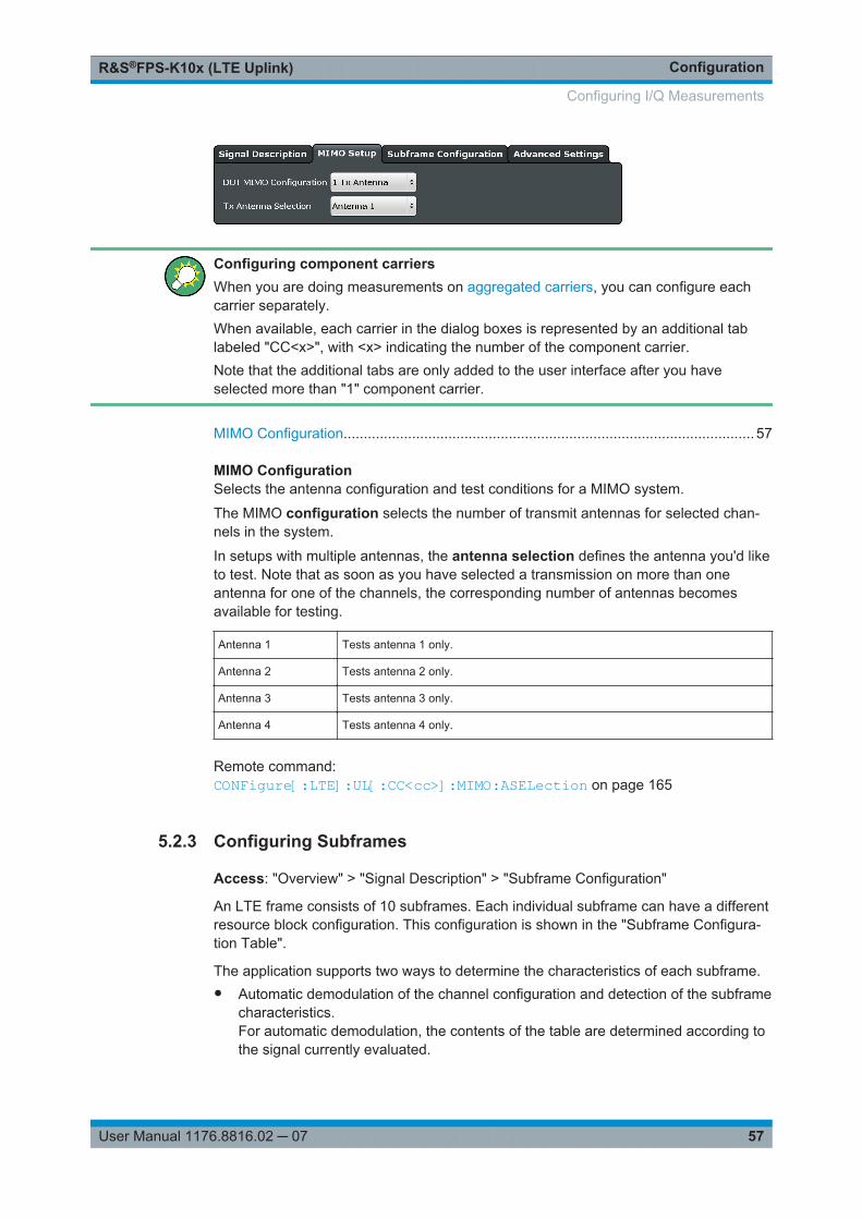
ConfigurationR&S®FPS-K10x (LTE Uplink)
57User Manual 1176.8816.02 ─ 07
Configuring component carriersWhen you are doing measurements on aggregated carriers, you can configure eachcarrier separately.When available, each carrier in the dialog boxes is represented by an additional tablabeled "CC<x>", with <x> indicating the number of the component carrier.Note that the additional tabs are only added to the user interface after you haveselected more than "1" component carrier.
MIMO Configuration...................................................................................................... 57
MIMO ConfigurationSelects the antenna configuration and test conditions for a MIMO system.
The MIMO configuration selects the number of transmit antennas for selected chan-nels in the system.
In setups with multiple antennas, the antenna selection defines the antenna you'd liketo test. Note that as soon as you have selected a transmission on more than oneantenna for one of the channels, the corresponding number of antennas becomesavailable for testing.
Antenna 1 Tests antenna 1 only.
Antenna 2 Tests antenna 2 only.
Antenna 3 Tests antenna 3 only.
Antenna 4 Tests antenna 4 only.
Remote command: CONFigure[:LTE]:UL[:CC<cc>]:MIMO:ASELection on page 165
5.2.3 Configuring Subframes
Access: "Overview" > "Signal Description" > "Subframe Configuration"
An LTE frame consists of 10 subframes. Each individual subframe can have a differentresource block configuration. This configuration is shown in the "Subframe Configura-tion Table".
The application supports two ways to determine the characteristics of each subframe.● Automatic demodulation of the channel configuration and detection of the subframe
characteristics.For automatic demodulation, the contents of the table are determined according tothe signal currently evaluated.
Configuring I/Q Measurements
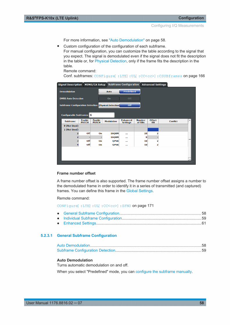
ConfigurationR&S®FPS-K10x (LTE Uplink)
58User Manual 1176.8816.02 ─ 07
For more information, see "Auto Demodulation" on page 58.● Custom configuration of the configuration of each subframe.
For manual configuration, you can customize the table according to the signal thatyou expect. The signal is demodulated even if the signal does not fit the descriptionin the table or, for Physical Detection, only if the frame fits the description in thetable.Remote command:Conf. subframes: CONFigure[:LTE]:UL[:CC<cc>]:CSUBframes on page 166
Frame number offset
A frame number offset is also supported. The frame number offset assigns a number tothe demodulated frame in order to identify it in a series of transmitted (and captured)frames. You can define this frame in the Global Settings.
Remote command:
CONFigure[:LTE]:UL[:CC<cc>]:SFNO on page 171
● General Subframe Configuration............................................................................ 58● Individual Subframe Configuration..........................................................................59● Enhanced Settings..................................................................................................61
5.2.3.1 General Subframe Configuration
Auto Demodulation........................................................................................................58Subframe Configuration Detection................................................................................ 59
Auto DemodulationTurns automatic demodulation on and off.
When you select "Predefined" mode, you can configure the subframe manually.
Configuring I/Q Measurements
ConfigurationR&S®FPS-K10x (LTE Uplink)
59User Manual 1176.8816.02 ─ 07
When you select "Auto" mode, the R&S FPS automatically detects the characteristicsof each subframe in the signal (resource allocation of the signal). Two methods ofdetection are supported:● Auto Demodulation, DMRS Auto Detection (Off)
This method automatically determines the characteristics for each subframe asshown in the Subframe Configuration Table.The table is populated accordingly.
● Subframe Configuration & DMRSAuto Demodulation, DMRS Auto Detection (On)This method automatically detects the PUSCH and SRS (i.e. no PUCCH can bedetected).To determine these characteristics, the software detects the CAZAC base parame-ters. Thus, the DMRS configuration parameters are not required for the synchroni-zation and therefore are not available using this method.Note however that it is not possible to derive the DMRS configuration parametersfrom the CAZAC base parameters so that the disabled DMRS configuration param-eters do not reflect the current parameters used for the synchronization. Also notethat it can happen that the software successfully synchronizes on non-3GPP sig-nals without a warning.
Automatic demodulation is not available if you suppress interferers for synchronizationis active.
Remote command: [SENSe:][LTE:]UL:DEMod:ACON on page 171
Subframe Configuration DetectionTurns the detection of the subframe configuration on and off.
When you select "Physical Detection", the R&S FPS compares the currently demodu-lated LTE frame to the subframe configuration you have defined in the table. The appli-cation only analyzes the LTE frame if the signal is consistent with the configuration.
When you turn the feature "Off", the software analyzes the signal even if it is not con-sistent with the current subframe configuration.
Subframe configuration detection is available if you are using a Predefined subframeconfiguration.
Remote command: [SENSe:][LTE:]UL:FORMat:SCD on page 171
5.2.3.2 Individual Subframe Configuration
The "Subframe Configuration Table" contains the characteristics for each subframe.The software supports a maximum uplink LTE frame size of 10 subframes. The sub-frame number in the table depends on the number of "Configurable Subframes" thatyou have defined or that have been detected for automatic demodulation.
Configuring I/Q Measurements

ConfigurationR&S®FPS-K10x (LTE Uplink)
60User Manual 1176.8816.02 ─ 07
Each row of the table represents one subframe. If the fields in a row are unavailable forediting, the corresponding subframe is occupied by a downlink subframe or the specialsubframe (in TDD systems).
Configuring component carriersWhen you are doing measurements on aggregated carriers, you can configure eachcarrier separately.When available, each carrier in the dialog boxes is represented by an additional tablabeled "CC<x>", with <x> indicating the number of the component carrier.Note that the additional tabs are only added to the user interface after you haveselected more than "1" component carrier.
Subframe Number.........................................................................................................60Enable PUCCH............................................................................................................. 60Enable PUSCH............................................................................................................. 60Modulation.....................................................................................................................61Enhanced Settings........................................................................................................ 61Number of RB............................................................................................................... 61Offset RB.......................................................................................................................61
Subframe NumberShows the number of a subframe.
Note that, depending on the TDD configuration, some subframes may not be availablefor editing. The R&S FPS labels those subframes "(not used)".
Enable PUCCHTurns the PUCCH in the corresponding subframe on and off.
Remote command: CONFigure[:LTE]:UL[:CC<cc>]:SUBFrame<sf>:ALLoc:CONT on page 166
Enable PUSCHTurns the PUSCH in the corresponding subframe on and off.
If you turn on a PUSCH, "Modulation", "Number of RBs" and "Offset RB" become avail-able.
Remote command: CONFigure[:LTE]:UL[:CC<cc>]:SUBFrame<sf>:ALLoc:CONT on page 166
Configuring I/Q Measurements

ConfigurationR&S®FPS-K10x (LTE Uplink)
61User Manual 1176.8816.02 ─ 07
ModulationSelects the modulation scheme for the corresponding PUSCH allocation.
The modulation scheme is either QPSK, 16QAM, 64QAM or 256QAM.
Remote command: CONFigure[:LTE]:UL[:CC<cc>]:SUBFrame<sf>:ALLoc:MODulationon page 167
Enhanced SettingsOpens a dialog box to configure enhanced functionality for selected channels in eachsubframe.
For more information see Enhanced Settings.
Number of RBSets the number of resource blocks the PUSCH allocation covers. The number ofresource blocks defines the size or bandwidth of the PUSCH allocation.
Remote command: CONFigure[:LTE]:UL[:CC<cc>]:SUBFrame<sf>:ALLoc[:CLUSter<cl>]:RBCount on page 170
Offset RBSets the resource block at which the PUSCH allocation begins.
Make sure not to allocate PUSCH allocations into regions reserved for PUCCH alloca-tions.
Remote command: CONFigure[:LTE]:UL[:CC<cc>]:SUBFrame<sf>:ALLoc[:CLUSter<cl>]:RBOFfset on page 170
5.2.3.3 Enhanced Settings
The "Enhanced Settings" contain functionality to define enhanced characteristics forselected channels.
Enhanced PUSCH Configuration.................................................................................. 61Enhanced Demodulation Reference Signal Configuration............................................62Enhanced PUCCH Configuration..................................................................................62
Enhanced PUSCH ConfigurationConfigures the PUSCH in individual subframes.
Resource Allocation Type 1Turns a clustered PUSCH allocation on and off. If on, a second row is added to thecorresponding allocation. This second row represents the second cluster.
You can define the number of resource block, the offset resource block and modulationfor each cluster. All other parameters are the same for both clusters.
Precoding Settings
Configuring I/Q Measurements
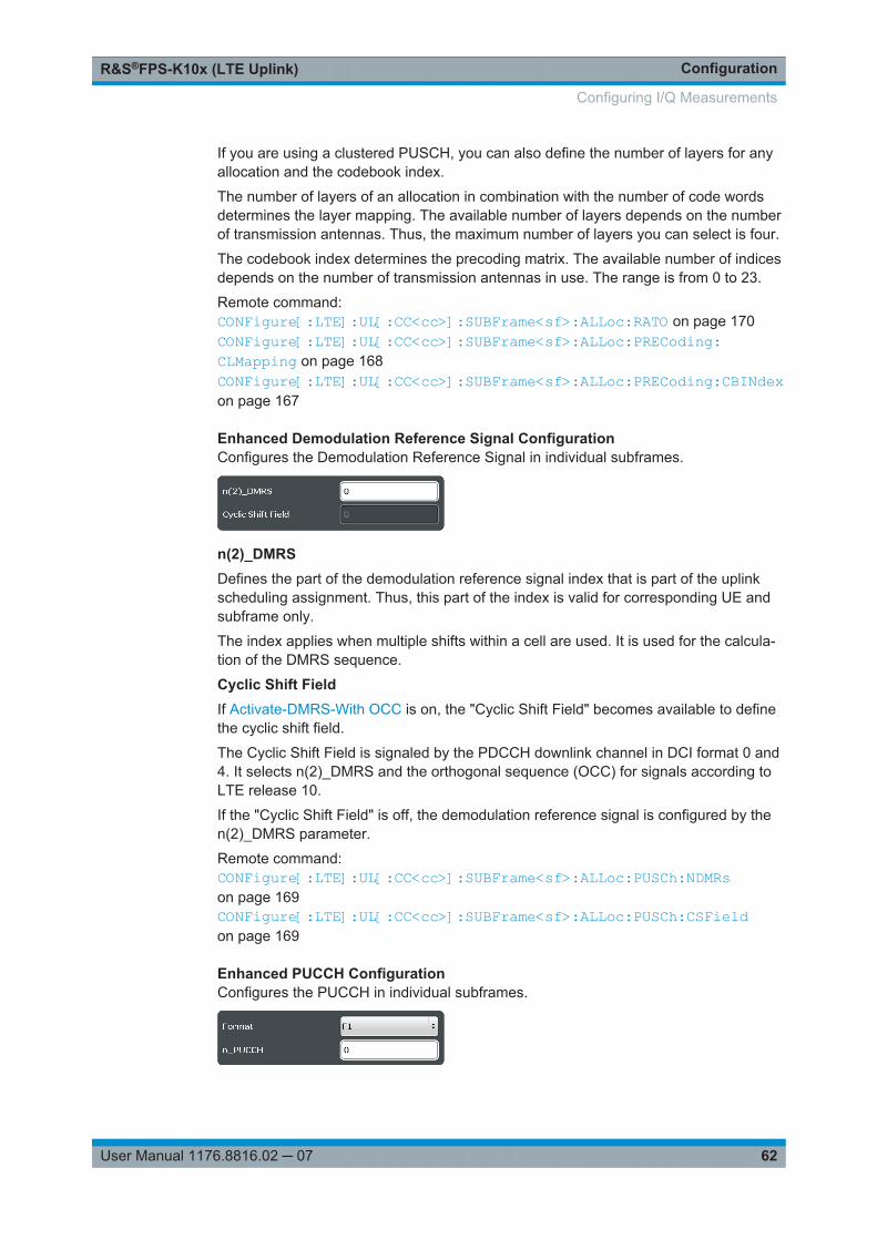
ConfigurationR&S®FPS-K10x (LTE Uplink)
62User Manual 1176.8816.02 ─ 07
If you are using a clustered PUSCH, you can also define the number of layers for anyallocation and the codebook index.
The number of layers of an allocation in combination with the number of code wordsdetermines the layer mapping. The available number of layers depends on the numberof transmission antennas. Thus, the maximum number of layers you can select is four.
The codebook index determines the precoding matrix. The available number of indicesdepends on the number of transmission antennas in use. The range is from 0 to 23.
Remote command: CONFigure[:LTE]:UL[:CC<cc>]:SUBFrame<sf>:ALLoc:RATO on page 170CONFigure[:LTE]:UL[:CC<cc>]:SUBFrame<sf>:ALLoc:PRECoding:CLMapping on page 168CONFigure[:LTE]:UL[:CC<cc>]:SUBFrame<sf>:ALLoc:PRECoding:CBINdexon page 167
Enhanced Demodulation Reference Signal ConfigurationConfigures the Demodulation Reference Signal in individual subframes.
n(2)_DMRSDefines the part of the demodulation reference signal index that is part of the uplinkscheduling assignment. Thus, this part of the index is valid for corresponding UE andsubframe only.
The index applies when multiple shifts within a cell are used. It is used for the calcula-tion of the DMRS sequence.
Cyclic Shift FieldIf Activate-DMRS-With OCC is on, the "Cyclic Shift Field" becomes available to definethe cyclic shift field.
The Cyclic Shift Field is signaled by the PDCCH downlink channel in DCI format 0 and4. It selects n(2)_DMRS and the orthogonal sequence (OCC) for signals according toLTE release 10.
If the "Cyclic Shift Field" is off, the demodulation reference signal is configured by then(2)_DMRS parameter.
Remote command: CONFigure[:LTE]:UL[:CC<cc>]:SUBFrame<sf>:ALLoc:PUSCh:NDMRson page 169CONFigure[:LTE]:UL[:CC<cc>]:SUBFrame<sf>:ALLoc:PUSCh:CSFieldon page 169
Enhanced PUCCH ConfigurationConfigures the PUCCH in individual subframes.
Configuring I/Q Measurements
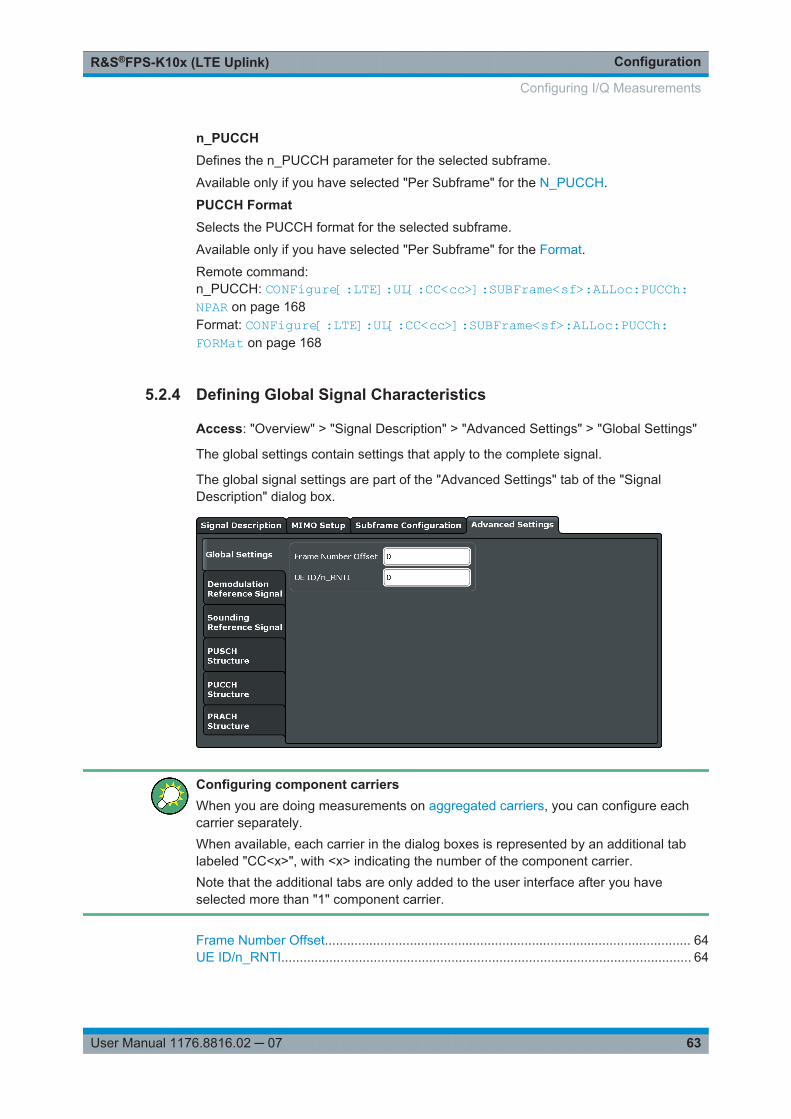
ConfigurationR&S®FPS-K10x (LTE Uplink)
63User Manual 1176.8816.02 ─ 07
n_PUCCHDefines the n_PUCCH parameter for the selected subframe.
Available only if you have selected "Per Subframe" for the N_PUCCH.
PUCCH FormatSelects the PUCCH format for the selected subframe.
Available only if you have selected "Per Subframe" for the Format.
Remote command: n_PUCCH: CONFigure[:LTE]:UL[:CC<cc>]:SUBFrame<sf>:ALLoc:PUCCh:NPAR on page 168Format: CONFigure[:LTE]:UL[:CC<cc>]:SUBFrame<sf>:ALLoc:PUCCh:FORMat on page 168
5.2.4 Defining Global Signal Characteristics
Access: "Overview" > "Signal Description" > "Advanced Settings" > "Global Settings"
The global settings contain settings that apply to the complete signal.
The global signal settings are part of the "Advanced Settings" tab of the "SignalDescription" dialog box.
Configuring component carriersWhen you are doing measurements on aggregated carriers, you can configure eachcarrier separately.When available, each carrier in the dialog boxes is represented by an additional tablabeled "CC<x>", with <x> indicating the number of the component carrier.Note that the additional tabs are only added to the user interface after you haveselected more than "1" component carrier.
Frame Number Offset................................................................................................... 64UE ID/n_RNTI............................................................................................................... 64
Configuring I/Q Measurements
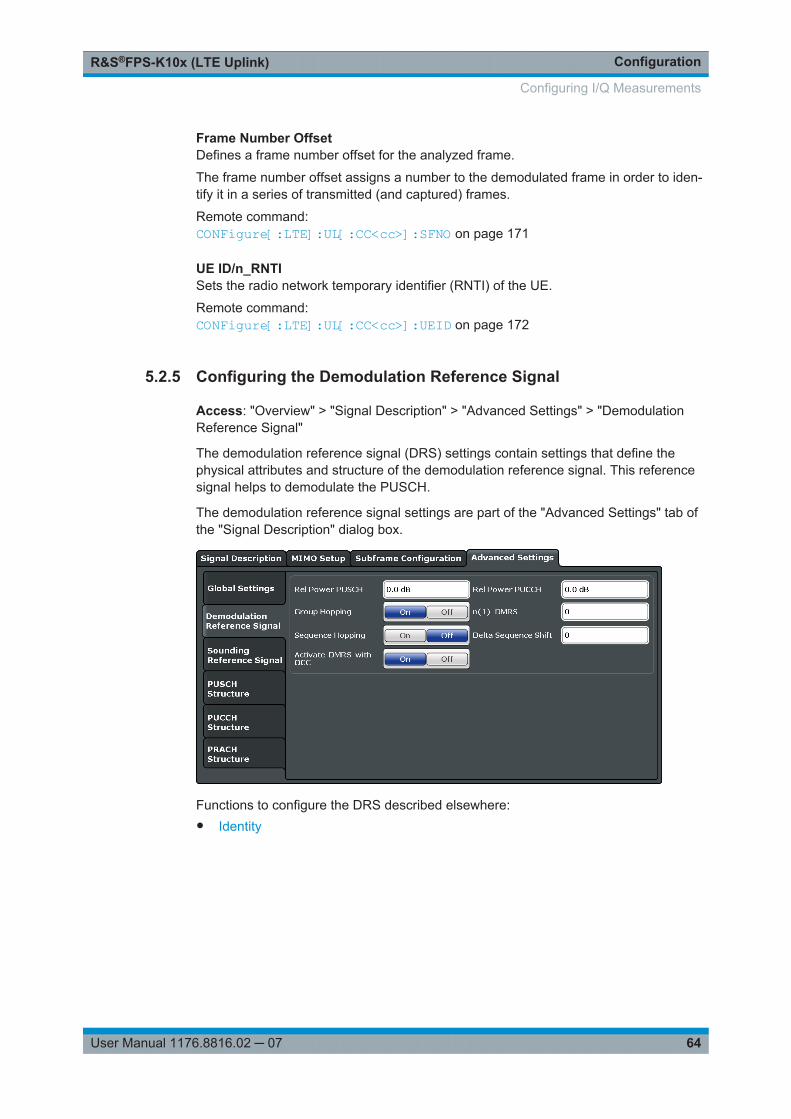
ConfigurationR&S®FPS-K10x (LTE Uplink)
64User Manual 1176.8816.02 ─ 07
Frame Number OffsetDefines a frame number offset for the analyzed frame.
The frame number offset assigns a number to the demodulated frame in order to iden-tify it in a series of transmitted (and captured) frames.
Remote command: CONFigure[:LTE]:UL[:CC<cc>]:SFNO on page 171
UE ID/n_RNTISets the radio network temporary identifier (RNTI) of the UE.
Remote command: CONFigure[:LTE]:UL[:CC<cc>]:UEID on page 172
5.2.5 Configuring the Demodulation Reference Signal
Access: "Overview" > "Signal Description" > "Advanced Settings" > "DemodulationReference Signal"
The demodulation reference signal (DRS) settings contain settings that define thephysical attributes and structure of the demodulation reference signal. This referencesignal helps to demodulate the PUSCH.
The demodulation reference signal settings are part of the "Advanced Settings" tab ofthe "Signal Description" dialog box.
Functions to configure the DRS described elsewhere:● Identity
Configuring I/Q Measurements
ConfigurationR&S®FPS-K10x (LTE Uplink)
65User Manual 1176.8816.02 ─ 07
Configuring component carriersWhen you are doing measurements on aggregated carriers, you can configure eachcarrier separately.When available, each carrier in the dialog boxes is represented by an additional tablabeled "CC<x>", with <x> indicating the number of the component carrier.Note that the additional tabs are only added to the user interface after you haveselected more than "1" component carrier.
Relative Power PUSCH................................................................................................ 65Group Hopping..............................................................................................................65Sequence Hopping........................................................................................................65Relative Power PUCCH................................................................................................ 65n(1)_DMRS................................................................................................................... 66Delta Sequence Shift.................................................................................................... 66Activate-DMRS-With OCC............................................................................................ 66
Relative Power PUSCHDefines the power of the DMRS relative to the power level of the PUSCH allocation inthe corresponding subframe (PDMRS_Offset).
The effective power level of the DMRS depends on the allocation of the subframe andis calculated as follows.
PDMRS = PUE + PPUSCH + PDMRS_Offset
The relative power of the DMRS is applied to all subframes.
The power of the PUSCH (PPUSCH) may be different in each subframe.
Remote command: CONFigure[:LTE]:UL[:CC<cc>]:DRS[:PUSCh]:POWer on page 174
Group HoppingTurns group hopping for the demodulation reference signal on and off.
The group hopping pattern is based on 17 hopping patterns and 30 sequence shift pat-terns. It is generated by a pseudo-random sequence generator.
If on, PUSCH and PUCCH use the same group hopping pattern.
Remote command: CONFigure[:LTE]:UL[:CC<cc>]:DRS:GRPHopping on page 173
Sequence HoppingTurns sequence hopping for the uplink demodulation reference signal on and off.
Sequence hopping is generated by a pseudo-random sequence generator.
Remote command: CONFigure[:LTE]:UL[:CC<cc>]:DRS:SEQHopping on page 174
Relative Power PUCCHDefines the power of the DMRS relative to the power level of the PUCCH allocation inthe corresponding subframe (PDMRS_Offset).
Configuring I/Q Measurements
ConfigurationR&S®FPS-K10x (LTE Uplink)
66User Manual 1176.8816.02 ─ 07
The effective power level of the DMRS depends on the allocation of the subframe andis calculated as follows.
PDMRS = PUE + PPUCCH + PDMRS_Offset
The relative power of the DMRS is applied to all subframes.
The power of the PUCCH (PPUCCH) may be different in each subframe.
Remote command: CONFigure[:LTE]:UL[:CC<cc>]:DRS:PUCCh:POWer on page 174
n(1)_DMRSDefines the part of the demodulation reference signal index that is broadcast. It is validfor the whole cell.
The index applies when multiple shifts within a cell are used. It is used for the calcula-tion of the DMRS sequence.
The n_DMRS parameter can be found in 3GPP TS36.211 V8.5.0, 5.5.2.1.1 Referencesignal sequence.
Remote command: CONFigure[:LTE]:UL[:CC<cc>]:DRS:NDMRs on page 173
Delta Sequence ShiftDefines the delta sequence shift ΔSS.
The standard defines a sequence shift pattern fss for the PUCCH. The correspondingsequence shift pattern for the PUSCH is a function of fss
PUCCH and the delta sequenceshift.
For more information refer to 3GPP TS 36.211, chapter 5.5.1.3 "Group Hopping".
Remote command: CONFigure[:LTE]:UL[:CC<cc>]:DRS:DSSHift on page 173
Activate-DMRS-With OCCTurns the configuration of the demodulation reference signal on a subframe basis viathe "Cyclic Shift Field" on and off.
If on, the "Cyclic Shift Field" becomes available. Otherwise, the demodulation refer-ence signal is configured by the n(2)_DMRS parameter.
Note that this parameter is automatically turned on if at least one of the physical chan-nels uses more than one antenna.
For more information see Enhanced Settings and MIMO Configuration.
Remote command: CONFigure[:LTE]:UL[:CC<cc>]:DRS:AOCC on page 172
5.2.6 Configuring the Sounding Reference Signal
Access: "Overview" > "Signal Description" > "Advanced Settings" > "Sounding Refer-ence Signal"
Configuring I/Q Measurements
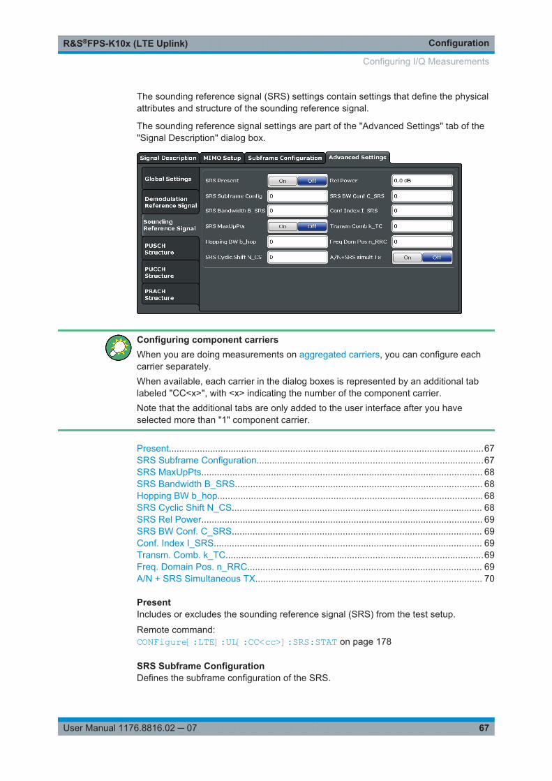
ConfigurationR&S®FPS-K10x (LTE Uplink)
67User Manual 1176.8816.02 ─ 07
The sounding reference signal (SRS) settings contain settings that define the physicalattributes and structure of the sounding reference signal.
The sounding reference signal settings are part of the "Advanced Settings" tab of the"Signal Description" dialog box.
Configuring component carriersWhen you are doing measurements on aggregated carriers, you can configure eachcarrier separately.When available, each carrier in the dialog boxes is represented by an additional tablabeled "CC<x>", with <x> indicating the number of the component carrier.Note that the additional tabs are only added to the user interface after you haveselected more than "1" component carrier.
Present..........................................................................................................................67SRS Subframe Configuration........................................................................................67SRS MaxUpPts............................................................................................................. 68SRS Bandwidth B_SRS................................................................................................ 68Hopping BW b_hop....................................................................................................... 68SRS Cyclic Shift N_CS................................................................................................. 68SRS Rel Power............................................................................................................. 69SRS BW Conf. C_SRS................................................................................................. 69Conf. Index I_SRS........................................................................................................ 69Transm. Comb. k_TC....................................................................................................69Freq. Domain Pos. n_RRC........................................................................................... 69A/N + SRS Simultaneous TX........................................................................................ 70
PresentIncludes or excludes the sounding reference signal (SRS) from the test setup.
Remote command: CONFigure[:LTE]:UL[:CC<cc>]:SRS:STAT on page 178
SRS Subframe ConfigurationDefines the subframe configuration of the SRS.
Configuring I/Q Measurements
ConfigurationR&S®FPS-K10x (LTE Uplink)
68User Manual 1176.8816.02 ─ 07
The subframe configuration of the SRS is specific to a cell. The UE sends a shortenedPUCCH/PUSCH in these subframes, regardless of whether the UE is configured tosend an SRS in the corresponding subframe or not.
Remote command: CONFigure[:LTE]:UL[:CC<cc>]:SRS:SUConfig on page 178
SRS MaxUpPtsTurns the parameter srs_MaxUpPts on and off.
srs_MaxUpPts controls the SRS transmission in the UpPTS field in TDD systems. Ifon, the SRS is transmitted in a frequency range of the UpPTS field that does not over-lap with resources reserved for PRACH preamble 4 transmissions.
To avoid an overlap, the number of SRS resource blocks otherwise determined byC_SRS and B_SRS is reconfigured.
Remote command: CONFigure[:LTE]:UL[:CC<cc>]:SRS:MUPT on page 177
SRS Bandwidth B_SRSDefines the parameter BSRS.
BSRS is a UE specific parameter that defines the bandwidth of the SRS. The SRS eitherspans the entire frequency bandwidth or uses frequency hopping when several narrow-band SRS cover the same total bandwidth.
The standard defines up to four bandwidths for the SRS. The most narrow SRS band-width (BSRS = 3) spans four resource blocks and is available for all channel bandwidths.The other three values of BSRS define more wideband SRS bandwidths. Their availabil-ity depends on the channel bandwidth.
The availability of SRS bandwidths additionally depends on the bandwidth configura-tion of the SRS (CSRS).
For more information refer to 3GPP TS 36.211, chapter 5.5.3.2 "Mapping to PhysicalResources" for the Sounding Reference Signal.
Remote command: CONFigure[:LTE]:UL[:CC<cc>]:SRS:BSRS on page 176
Hopping BW b_hopDefines the parameter bhop.
bhop is a UE specific parameter that defines the frequency hopping bandwidth. SRS fre-quency hopping is active if bhop < BSRS.
For more information refer to 3GPP TS 36.211, chapter 5.5.3.2 "Mapping to PhysicalResources" for the Sounding Reference Signal.
Remote command: CONFigure[:LTE]:UL[:CC<cc>]:SRS:BHOP on page 175
SRS Cyclic Shift N_CSDefines the cyclic shift (nCS) used for the generation of the SRS CAZAC sequence.
Configuring I/Q Measurements
ConfigurationR&S®FPS-K10x (LTE Uplink)
69User Manual 1176.8816.02 ─ 07
Because the different shifts of the same Zadoff-Chu sequence are orthogonal to eachother, applying different SRS cyclic shifts can be used to schedule different UE tosimultaneously transmit their SRS.
Remote command: CONFigure[:LTE]:UL[:CC<cc>]:SRS:CYCS on page 176
SRS Rel PowerDefines the power of the SRS relative to the power of the corresponding UE (PSRS_Off-
set).
The effective power level of the SRS is calculated as follows.
PSRS = PUE + PSRS_Offset
The relative power of the SRS is applied to all subframes.
Remote command: CONFigure[:LTE]:UL[:CC<cc>]:SRS:POWer on page 178
SRS BW Conf. C_SRSDefines the bandwidth configuration of the SRS.
The bandwidth configuration is a cell-specific parameter that, in combination with theSRS bandwidth and the channel bandwidth, defines the length of the sounding refer-ence signal sequence. For more information on the calculation, refer to 3GPP TS36.211 chapter 5.5.3 "Sounding Reference Signal".
Remote command: CONFigure[:LTE]:UL[:CC<cc>]:SRS:CSRS on page 176
Conf. Index I_SRSDefines the configuration index of the SRS.
The configuration index ISRS is a cell specific parameter that determines the SRS perio-dicity (TSRS) and the SRS subframe offset (Toffset). The effects of the configuration indexon TSRS and Toffset depends on the duplexing mode.
For more information refer to 3GPP TS 36.213, Table 8.2-1 (FDD) and 8.2-2 (TDD).
Remote command: CONFigure[:LTE]:UL[:CC<cc>]:SRS:ISRS on page 177
Transm. Comb. k_TCDefines the transmission comb kTC.
The transmission comb. is a UE specific parameter. For more information refer to3GPP TS 36.211, chapter 5.5.3.2 "Mapping to Physical Resources" for the SoundingReference Signal.
Remote command: CONFigure[:LTE]:UL[:CC<cc>]:SRS:TRComb on page 179
Freq. Domain Pos. n_RRCDefines the parameter nRRC.
nRRC is a UE specific parameter and determines the starting physical resource block ofthe SRS transmission.
Configuring I/Q Measurements
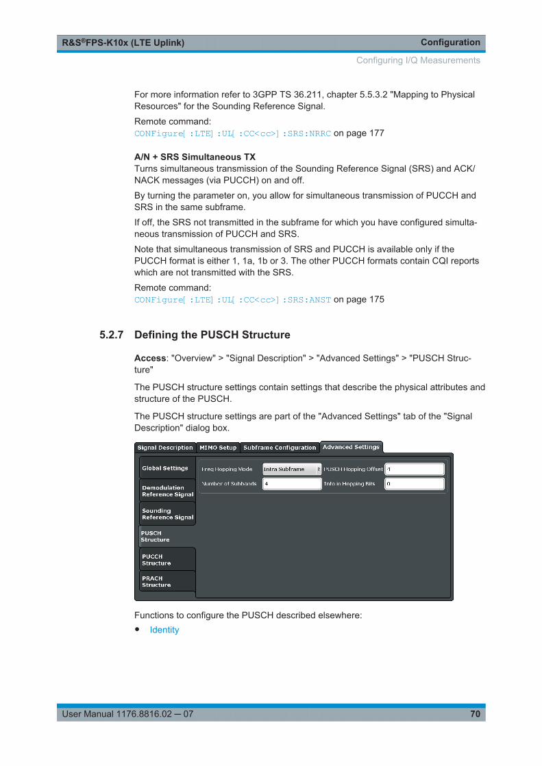
ConfigurationR&S®FPS-K10x (LTE Uplink)
70User Manual 1176.8816.02 ─ 07
For more information refer to 3GPP TS 36.211, chapter 5.5.3.2 "Mapping to PhysicalResources" for the Sounding Reference Signal.
Remote command: CONFigure[:LTE]:UL[:CC<cc>]:SRS:NRRC on page 177
A/N + SRS Simultaneous TXTurns simultaneous transmission of the Sounding Reference Signal (SRS) and ACK/NACK messages (via PUCCH) on and off.
By turning the parameter on, you allow for simultaneous transmission of PUCCH andSRS in the same subframe.
If off, the SRS not transmitted in the subframe for which you have configured simulta-neous transmission of PUCCH and SRS.
Note that simultaneous transmission of SRS and PUCCH is available only if thePUCCH format is either 1, 1a, 1b or 3. The other PUCCH formats contain CQI reportswhich are not transmitted with the SRS.
Remote command: CONFigure[:LTE]:UL[:CC<cc>]:SRS:ANST on page 175
5.2.7 Defining the PUSCH Structure
Access: "Overview" > "Signal Description" > "Advanced Settings" > "PUSCH Struc-ture"
The PUSCH structure settings contain settings that describe the physical attributes andstructure of the PUSCH.
The PUSCH structure settings are part of the "Advanced Settings" tab of the "SignalDescription" dialog box.
Functions to configure the PUSCH described elsewhere:● Identity
Configuring I/Q Measurements
ConfigurationR&S®FPS-K10x (LTE Uplink)
71User Manual 1176.8816.02 ─ 07
Configuring component carriersWhen you are doing measurements on aggregated carriers, you can configure eachcarrier separately.When available, each carrier in the dialog boxes is represented by an additional tablabeled "CC<x>", with <x> indicating the number of the component carrier.Note that the additional tabs are only added to the user interface after you haveselected more than "1" component carrier.
Frequency Hopping Mode.............................................................................................71Number of Subbands.................................................................................................... 71PUSCH Hopping Offset.................................................................................................71Info. in Hopping Bits...................................................................................................... 71
Frequency Hopping ModeSelects the frequency hopping mode of the PUSCH.
Several hopping modes are supported.● None
No frequency hopping.● Inter Subframe Hopping
PUSCH changes the frequency from one subframe to another.● Intra Subframe Hopping
PUSCH also changes the frequency within a subframe.
Remote command: CONFigure[:LTE]:UL[:CC<cc>]:PUSCh:FHMode on page 179
Number of SubbandsDefines the number of subbands reserved for PUSCH.
For more information refer to 3GPP TS 36.211, chapter 5.5.3.2 "Mapping to PhysicalResources" for the Sounding Reference Signal.
Remote command: CONFigure[:LTE]:UL[:CC<cc>]:PUSCh:NOSM on page 180
PUSCH Hopping OffsetDefines the PUSCH Hopping Offset NRB
HO.
The PUSCH Hopping Offset determines the first physical resource block and the maxi-mum number of physical resource blocks available for PUSCH transmission if PUSCHfrequency hopping is active.
Remote command: CONFigure[:LTE]:UL[:CC<cc>]:PUSCh:FHOFfset on page 179
Info. in Hopping BitsDefines the information available in the hopping bits according to the PDCCH DCI for-mat 0 hopping bit definition.
The information in the hopping bits determines whether type 1 or type 2 hopping isused in the subframe and, in case of type 1, additionally determines the exact hoppingfunction to use.
Configuring I/Q Measurements
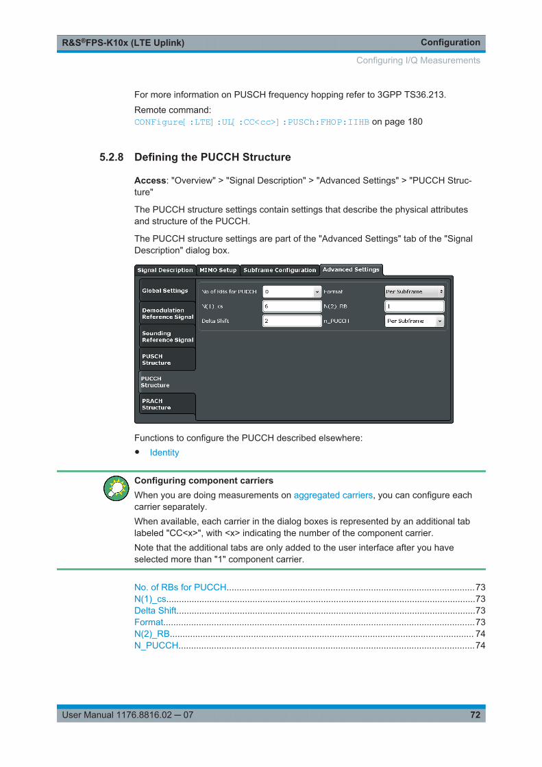
ConfigurationR&S®FPS-K10x (LTE Uplink)
72User Manual 1176.8816.02 ─ 07
For more information on PUSCH frequency hopping refer to 3GPP TS36.213.
Remote command: CONFigure[:LTE]:UL[:CC<cc>]:PUSCh:FHOP:IIHB on page 180
5.2.8 Defining the PUCCH Structure
Access: "Overview" > "Signal Description" > "Advanced Settings" > "PUCCH Struc-ture"
The PUCCH structure settings contain settings that describe the physical attributesand structure of the PUCCH.
The PUCCH structure settings are part of the "Advanced Settings" tab of the "SignalDescription" dialog box.
Functions to configure the PUCCH described elsewhere:● Identity
Configuring component carriersWhen you are doing measurements on aggregated carriers, you can configure eachcarrier separately.When available, each carrier in the dialog boxes is represented by an additional tablabeled "CC<x>", with <x> indicating the number of the component carrier.Note that the additional tabs are only added to the user interface after you haveselected more than "1" component carrier.
No. of RBs for PUCCH..................................................................................................73N(1)_cs..........................................................................................................................73Delta Shift......................................................................................................................73Format...........................................................................................................................73N(2)_RB........................................................................................................................ 74N_PUCCH.....................................................................................................................74
Configuring I/Q Measurements
ConfigurationR&S®FPS-K10x (LTE Uplink)
73User Manual 1176.8816.02 ─ 07
No. of RBs for PUCCHDefines the number of resource blocks reserved for PUCCH.
The resource blocks for PUCCH are always allocated at the edges of the LTE spec-trum.
In case of an even number of PUCCH resource blocks, half of the available PUCCHresource blocks is allocated on the lower, the other half on the upper edge of the LTEspectrum (outermost resource blocks).
In case of an odd number of PUCCH resource blocks, the number of resource blockson the lower edge is one resource block larger than the number of resource blocks onthe upper edge of the LTE spectrum.
If you select the "Auto" menu item, the application automatically detects the number ofRBs.
Remote command: CONFigure[:LTE]:UL[:CC<cc>]:PUCCh:NORB on page 183
N(1)_csDefines the number of cyclic shifts used for PUCCH format 1/1a/1b in a resource blockused for a combination of the formats 1/1a/1b and 2/2a/2b.
Only one resource block per slot can support a combination of the PUCCH formats1/1a/1b and 2/2a/2b.
The number of cyclic shifts available for PUCCH format 2/2a/2b N(2)_cs in a block withcombination of PUCCH formats is calculated as follows.
N(2)_cs = 12 - N(1)_cs - 2
For more information refer to 3GPP TS36.211, chapter 5.4 "Physical Uplink ControlChannel".
Remote command: CONFigure[:LTE]:UL[:CC<cc>]:PUCCh:N1CS on page 182
Delta ShiftDefines the delta shift parameter.
The delta shift is the difference between two adjacent PUCCH resource indices withthe same orthogonal cover sequence (OC).
It determines the number of available sequences in a resource block that can be usedfor PUCCH formats 1/1a/1b.
For more information refer to 3GPP TS36.211, chapter 5.4 "Physical Uplink ControlChannel".
Remote command: CONFigure[:LTE]:UL[:CC<cc>]:PUCCh:DESHift on page 181
FormatSelects the format of the PUCCH.
You can define the PUCCH format for all subframes or define the PUCCH format foreach subframe individually.● F1, F1a, F1b, F2, F2a, F2b, F3
Selects the PUCCH format globally for every subframe.
Configuring I/Q Measurements

ConfigurationR&S®FPS-K10x (LTE Uplink)
74User Manual 1176.8816.02 ─ 07
● Per SubframeYou can select the PUCCH format for each subframe separately in the EnhancedSettings of the "Subframe Configuration".
Note that formats F2a and F2b are only supported for normal cyclic prefix length.
For more information refer to 3GPP TS36.211, table 5.4-1 "Supported PUCCH For-mats".
Remote command: CONFigure[:LTE]:UL[:CC<cc>]:PUCCh:FORMat on page 181
N(2)_RBDefines bandwidth in terms of resource blocks that are reserved for PUCCH formats2/2a/2b transmission in each subframe.
Since there can be only one resource block per slot that supports a combination of thePUCCH formats 1/1a/1b and 2/2a/2b, the number of resource block(s) per slot availa-ble for PUCCH format 1/1a/1b is determined by N(2)_RB.
For more information refer to 3GPP TS36.211, chapter 5.4 "Physical Uplink ControlChannel".
Remote command: CONFigure[:LTE]:UL[:CC<cc>]:PUCCh:N2RB on page 182
N_PUCCHDefines the resource index for PUCCH format 1/1a/1b respectively 2/2a/2b.
You can select the PUCCH format manually or allow the application to determine thePUCCH format automatically based on the measurement.
It is also possible to define NPUCCH on a subframe level by selecting the "Per Subframe"menu item. For more information see Chapter 5.2.3, "Configuring Subframes",on page 57.
Remote command: CONFigure[:LTE]:UL[:CC<cc>]:PUCCh:NPAR on page 183
5.2.9 Defining the PRACH Structure
Access: "Overview" > "Signal Description" > "Advanced Settings" > "PRACH Struc-ture"
The PRACH structure settings contain settings that describe the physical attributes andstructure of the PRACH.
The PRACH structure settings are part of the "Advanced Settings" tab of the "SignalDescription" dialog box.
Configuring I/Q Measurements
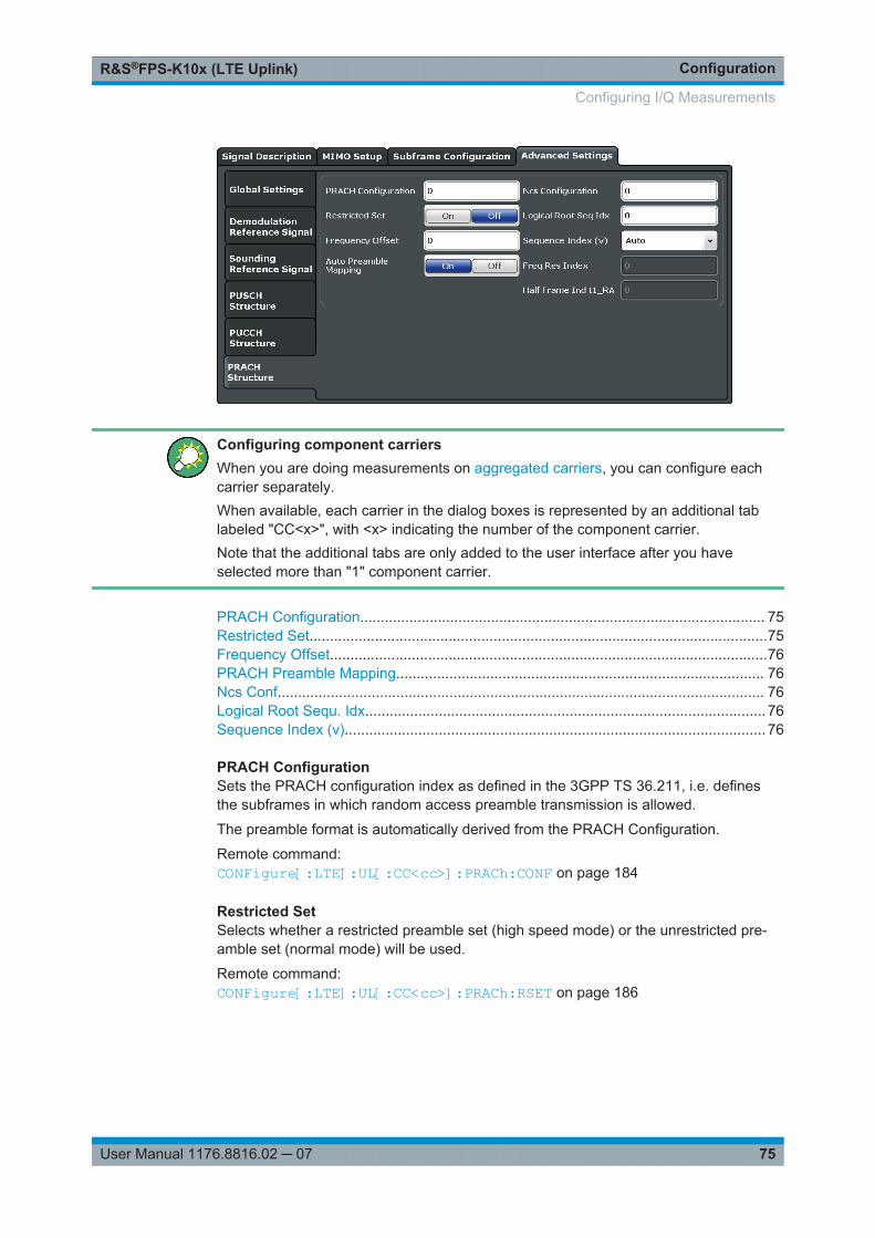
ConfigurationR&S®FPS-K10x (LTE Uplink)
75User Manual 1176.8816.02 ─ 07
Configuring component carriersWhen you are doing measurements on aggregated carriers, you can configure eachcarrier separately.When available, each carrier in the dialog boxes is represented by an additional tablabeled "CC<x>", with <x> indicating the number of the component carrier.Note that the additional tabs are only added to the user interface after you haveselected more than "1" component carrier.
PRACH Configuration................................................................................................... 75Restricted Set................................................................................................................75Frequency Offset...........................................................................................................76PRACH Preamble Mapping.......................................................................................... 76Ncs Conf....................................................................................................................... 76Logical Root Sequ. Idx.................................................................................................. 76Sequence Index (v)....................................................................................................... 76
PRACH ConfigurationSets the PRACH configuration index as defined in the 3GPP TS 36.211, i.e. definesthe subframes in which random access preamble transmission is allowed.
The preamble format is automatically derived from the PRACH Configuration.
Remote command: CONFigure[:LTE]:UL[:CC<cc>]:PRACh:CONF on page 184
Restricted SetSelects whether a restricted preamble set (high speed mode) or the unrestricted pre-amble set (normal mode) will be used.
Remote command: CONFigure[:LTE]:UL[:CC<cc>]:PRACh:RSET on page 186
Configuring I/Q Measurements

ConfigurationR&S®FPS-K10x (LTE Uplink)
76User Manual 1176.8816.02 ─ 07
Frequency OffsetThe "Frequency Offset" defines the PRACH frequency offset for preamble formats 0 to3 as defined in the 3GPP TS 36.211. The frequency offset determines the first physicalresource block available for PRACH expressed as a physical resource block number.
Remote command: CONFigure[:LTE]:UL[:CC<cc>]:PRACh:FOFFset on page 185
PRACH Preamble MappingThe frequency resource index fRA and the half frame indicator t1RA are necessary forclear specification of the physical resource mapping of the PRACH, in case a PRACHconfiguration index has more than one mapping alternative.
If you turn on the "Auto Preamble Mapping", the software automatically detects fRA andt1RA.
The values for both parameters are defined in table '5.7.1-4: Frame structure type 2random access preamble mapping in time and frequency' (3GPP TS 36.211 v10.2.0).
The frequency resource index and half frame indicator are available in TDD mode.
Remote command: CONFigure[:LTE]:UL[:CC<cc>]:PRACh:APM on page 184CONFigure[:LTE]:UL[:CC<cc>]:PRACh:FRINdex on page 185CONFigure[:LTE]:UL[:CC<cc>]:PRACh:HFINdicator on page 185
Ncs ConfSelects the Ncs configuration, i.e. determines the Ncs value set according to TS36.211, table 5.7.2.-2 and 5.7.2-3.
Remote command: CONFigure[:LTE]:UL[:CC<cc>]:PRACh:NCSC on page 185
Logical Root Sequ. IdxSelects the logical root sequence index.
The logical root sequence index is used to generate preamble sequences. It is provi-ded by higher layers.
Remote command: CONFigure[:LTE]:UL[:CC<cc>]:PRACh:RSEQ on page 186
Sequence Index (v)Defines the sequence index (v).
The sequence index controls which of the 64 preambles available in a cell is used.
If you select the "Auto" menu item, the software automatically selects the requiredsequence index.
Remote command: CONFigure[:LTE]:UL[:CC<cc>]:PRACh:SINDex on page 186
5.2.10 Selecting the Input Source
The application supports several input sources and outputs.
Configuring I/Q Measurements
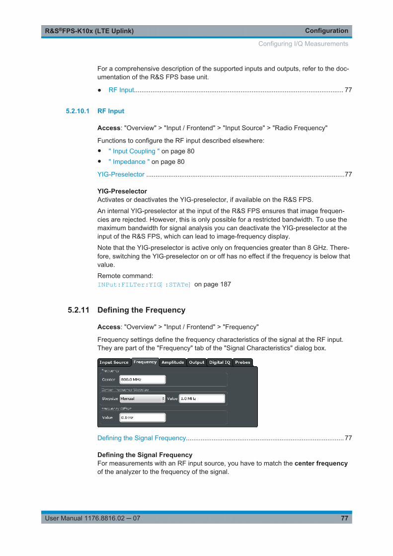
ConfigurationR&S®FPS-K10x (LTE Uplink)
77User Manual 1176.8816.02 ─ 07
For a comprehensive description of the supported inputs and outputs, refer to the doc-umentation of the R&S FPS base unit.
● RF Input.................................................................................................................. 77
5.2.10.1 RF Input
Access: "Overview" > "Input / Frontend" > "Input Source" > "Radio Frequency"
Functions to configure the RF input described elsewhere:● " Input Coupling " on page 80● " Impedance " on page 80
YIG-Preselector ............................................................................................................77
YIG-PreselectorActivates or deactivates the YIG-preselector, if available on the R&S FPS.
An internal YIG-preselector at the input of the R&S FPS ensures that image frequen-cies are rejected. However, this is only possible for a restricted bandwidth. To use themaximum bandwidth for signal analysis you can deactivate the YIG-preselector at theinput of the R&S FPS, which can lead to image-frequency display.
Note that the YIG-preselector is active only on frequencies greater than 8 GHz. There-fore, switching the YIG-preselector on or off has no effect if the frequency is below thatvalue.
Remote command: INPut:FILTer:YIG[:STATe] on page 187
5.2.11 Defining the Frequency
Access: "Overview" > "Input / Frontend" > "Frequency"
Frequency settings define the frequency characteristics of the signal at the RF input.They are part of the "Frequency" tab of the "Signal Characteristics" dialog box.
Defining the Signal Frequency...................................................................................... 77
Defining the Signal FrequencyFor measurements with an RF input source, you have to match the center frequencyof the analyzer to the frequency of the signal.
Configuring I/Q Measurements

ConfigurationR&S®FPS-K10x (LTE Uplink)
78User Manual 1176.8816.02 ─ 07
The available frequency range depends on the hardware configuration of the analyzeryou are using.
In addition to the frequency itself, you can also define a frequency stepsize. The fre-quency stepsize defines the extent of a frequency change if you change it, for examplewith the rotary knob. Define the stepsize in two ways.● = Center
One frequency step corresponds to the current center frequency.● Manual
Define any stepsize you need.
Remote command: Center frequency: [SENSe:]FREQuency:CENTer[:CC<cc>] on page 188Frequency stepsize: [SENSe:]FREQuency:CENTer:STEP on page 189Frequency offset: [SENSe]:FREQuency:CENTer[:CC<cc>]:OFFSet on page 188
5.2.12 Defining Level Characteristics
Access: "Overview" > "Input / Frontend" > "Amplitude"
Amplitude settings define the expected level characteristics of the signal at the RFinput.
Defining a Reference Level...........................................................................................78Attenuating the Signal................................................................................................... 79Input Coupling .............................................................................................................. 80Impedance ................................................................................................................... 80
Defining a Reference LevelThe reference level is the power level the analyzer expects at the RF input. Keep inmind that the power level at the RF input is the peak envelope power for signals with ahigh crest factor like LTE.
To get the best dynamic range, you have to set the reference level as low as possible.At the same time, make sure that the maximum signal level does not exceed the refer-ence level. If it does, it will overload the A/D converter, regardless of the signal power.Measurement results can deteriorate (e.g. EVM), especially for measurements withmore than one active channel near the one you are trying to measure (± 6 MHz).
Configuring I/Q Measurements
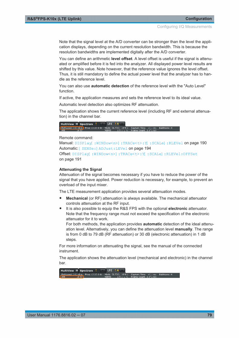
ConfigurationR&S®FPS-K10x (LTE Uplink)
79User Manual 1176.8816.02 ─ 07
Note that the signal level at the A/D converter can be stronger than the level the appli-cation displays, depending on the current resolution bandwidth. This is because theresolution bandwidths are implemented digitally after the A/D converter.
You can define an arithmetic level offset. A level offset is useful if the signal is attenu-ated or amplified before it is fed into the analyzer. All displayed power level results areshifted by this value. Note however, that the reference value ignores the level offset.Thus, it is still mandatory to define the actual power level that the analyzer has to han-dle as the reference level.
You can also use automatic detection of the reference level with the "Auto Level"function.
If active, the application measures and sets the reference level to its ideal value.
Automatic level detection also optimizes RF attenuation.
The application shows the current reference level (including RF and external attenua-tion) in the channel bar.
Remote command: Manual: DISPlay[:WINDow<n>]:TRACe<t>:Y[:SCALe]:RLEVel on page 190Automatic: [SENSe:]ADJust:LEVel on page 194Offset: DISPlay[:WINDow<n>]:TRACe<t>:Y[:SCALe]:RLEVel:OFFSeton page 191
Attenuating the SignalAttenuation of the signal becomes necessary if you have to reduce the power of thesignal that you have applied. Power reduction is necessary, for example, to prevent anoverload of the input mixer.
The LTE measurement application provides several attenuation modes.● Mechanical (or RF) attenuation is always available. The mechanical attenuator
controls attenuation at the RF input.● It is also possible to equip the R&S FPS with the optional electronic attenuator.
Note that the frequency range must not exceed the specification of the electronicattenuator for it to work.For both methods, the application provides automatic detection of the ideal attenu-ation level. Alternatively, you can define the attenuation level manually. The rangeis from 0 dB to 79 dB (RF attenuation) or 30 dB (electronic attenuation) in 1 dBsteps.
For more information on attenuating the signal, see the manual of the connectedinstrument.
The application shows the attenuation level (mechanical and electronic) in the channelbar.
Configuring I/Q Measurements
ConfigurationR&S®FPS-K10x (LTE Uplink)
80User Manual 1176.8816.02 ─ 07
Remote command: RF attenuation: INPut:ATTenuation on page 191RF attenuation: INPut:ATTenuation:AUTO on page 191Electronic attenuation: INPut<n>:EATT:STATe on page 193Electronic attenuation: INPut<n>:EATT:AUTO on page 193Electronic attenuation: INPut<n>:EATT on page 193
Input CouplingThe RF input of the R&S FPS can be coupled by alternating current (AC) or direct cur-rent (DC).
AC coupling blocks any DC voltage from the input signal. This is the default setting toprevent damage to the instrument. Very low frequencies in the input signal may be dis-torted.
However, some specifications require DC coupling. In this case, you must protect theinstrument from damaging DC input voltages manually. For details, refer to the datasheet.
Remote command: INPut:COUPling on page 192
ImpedanceFor some measurements, the reference impedance for the measured levels of theR&S FPS can be set to 50 Ω or 75 Ω.
Select 75 Ω if the 50 Ω input impedance is transformed to a higher impedance using a75 Ω adapter of the RAZ type. (That corresponds to 25Ω in series to the input impe-dance of the instrument.) The correction value in this case is 1.76 dB = 10 log (75Ω/50Ω).
This value also affects the unit conversion.
Remote command: INPut:IMPedance on page 192
5.2.13 Configuring the Data Capture
Access: "Overview" > "Trig / Sig Capture" > "Signal Capture"
The data capture settings contain settings that control the data capture.
The data capture settings are part of the "Signal Capture" tab of the "Trigger/SignalCapture" dialog box.
Configuring I/Q Measurements
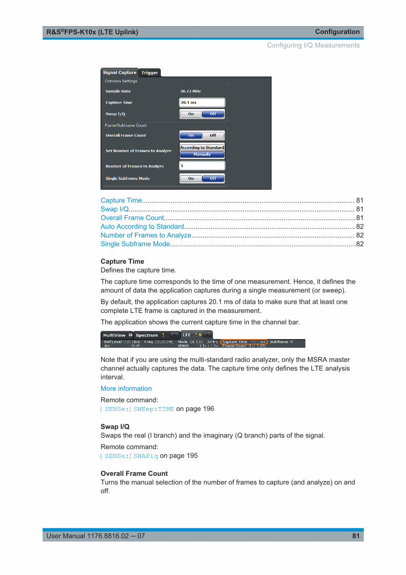
ConfigurationR&S®FPS-K10x (LTE Uplink)
81User Manual 1176.8816.02 ─ 07
Capture Time................................................................................................................ 81Swap I/Q....................................................................................................................... 81Overall Frame Count.....................................................................................................81Auto According to Standard.......................................................................................... 82Number of Frames to Analyze...................................................................................... 82Single Subframe Mode..................................................................................................82
Capture TimeDefines the capture time.
The capture time corresponds to the time of one measurement. Hence, it defines theamount of data the application captures during a single measurement (or sweep).
By default, the application captures 20.1 ms of data to make sure that at least onecomplete LTE frame is captured in the measurement.
The application shows the current capture time in the channel bar.
Note that if you are using the multi-standard radio analyzer, only the MSRA masterchannel actually captures the data. The capture time only defines the LTE analysisinterval.
More information
Remote command: [SENSe:]SWEep:TIME on page 196
Swap I/QSwaps the real (I branch) and the imaginary (Q branch) parts of the signal.
Remote command: [SENSe:]SWAPiq on page 195
Overall Frame CountTurns the manual selection of the number of frames to capture (and analyze) on andoff.
Configuring I/Q Measurements
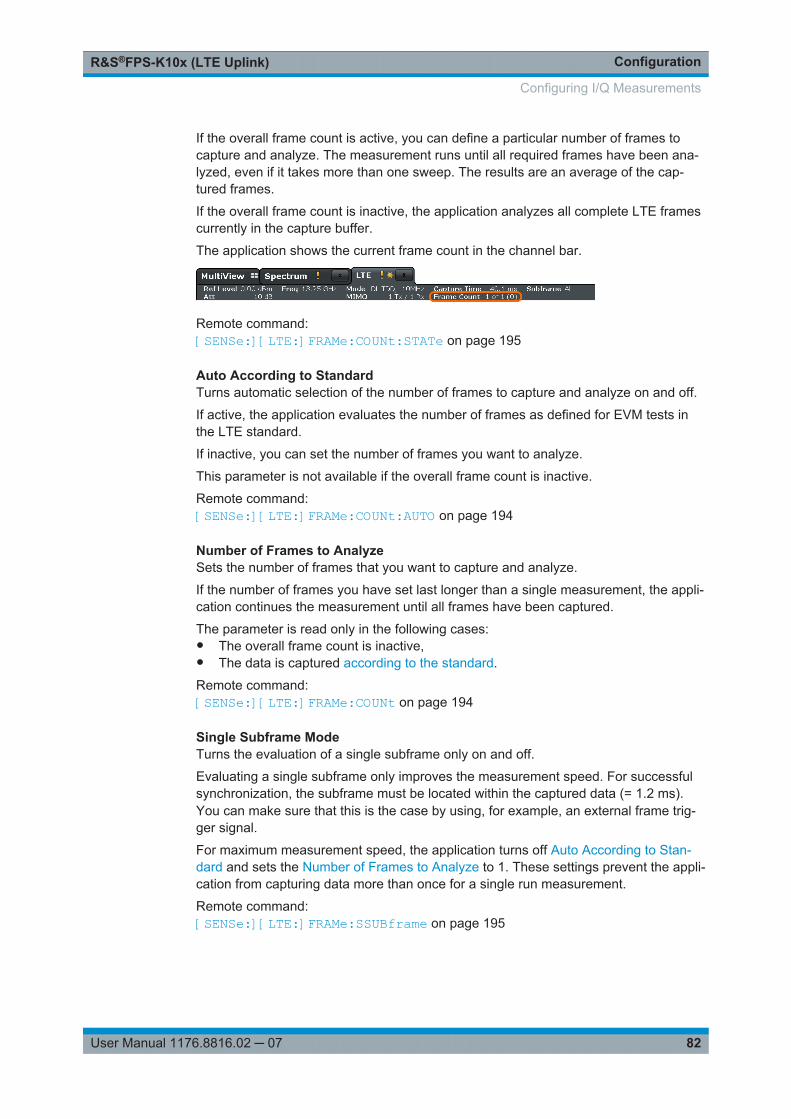
ConfigurationR&S®FPS-K10x (LTE Uplink)
82User Manual 1176.8816.02 ─ 07
If the overall frame count is active, you can define a particular number of frames tocapture and analyze. The measurement runs until all required frames have been ana-lyzed, even if it takes more than one sweep. The results are an average of the cap-tured frames.
If the overall frame count is inactive, the application analyzes all complete LTE framescurrently in the capture buffer.
The application shows the current frame count in the channel bar.
Remote command: [SENSe:][LTE:]FRAMe:COUNt:STATe on page 195
Auto According to StandardTurns automatic selection of the number of frames to capture and analyze on and off.
If active, the application evaluates the number of frames as defined for EVM tests inthe LTE standard.
If inactive, you can set the number of frames you want to analyze.
This parameter is not available if the overall frame count is inactive.
Remote command: [SENSe:][LTE:]FRAMe:COUNt:AUTO on page 194
Number of Frames to AnalyzeSets the number of frames that you want to capture and analyze.
If the number of frames you have set last longer than a single measurement, the appli-cation continues the measurement until all frames have been captured.
The parameter is read only in the following cases:● The overall frame count is inactive,● The data is captured according to the standard.
Remote command: [SENSe:][LTE:]FRAMe:COUNt on page 194
Single Subframe ModeTurns the evaluation of a single subframe only on and off.
Evaluating a single subframe only improves the measurement speed. For successfulsynchronization, the subframe must be located within the captured data (= 1.2 ms).You can make sure that this is the case by using, for example, an external frame trig-ger signal.
For maximum measurement speed, the application turns off Auto According to Stan-dard and sets the Number of Frames to Analyze to 1. These settings prevent the appli-cation from capturing data more than once for a single run measurement.
Remote command: [SENSe:][LTE:]FRAMe:SSUBframe on page 195
Configuring I/Q Measurements
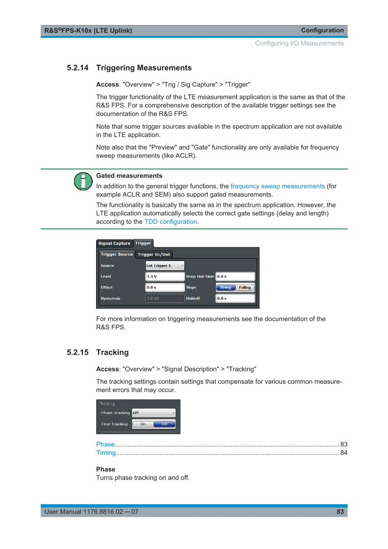
ConfigurationR&S®FPS-K10x (LTE Uplink)
83User Manual 1176.8816.02 ─ 07
5.2.14 Triggering Measurements
Access: "Overview" > "Trig / Sig Capture" > "Trigger"
The trigger functionality of the LTE measurement application is the same as that of theR&S FPS. For a comprehensive description of the available trigger settings see thedocumentation of the R&S FPS.
Note that some trigger sources available in the spectrum application are not availablein the LTE application.
Note also that the "Preview" and "Gate" functionality are only available for frequencysweep measurements (like ACLR).
Gated measurementsIn addition to the general trigger functions, the frequency sweep measurements (forexample ACLR and SEM) also support gated measurements.The functionality is basically the same as in the spectrum application. However, theLTE application automatically selects the correct gate settings (delay and length)according to the TDD configuration.
For more information on triggering measurements see the documentation of theR&S FPS.
5.2.15 Tracking
Access: "Overview" > "Signal Description" > "Tracking"
The tracking settings contain settings that compensate for various common measure-ment errors that may occur.
Phase............................................................................................................................ 83Timing........................................................................................................................... 84
PhaseTurns phase tracking on and off.
Configuring I/Q Measurements
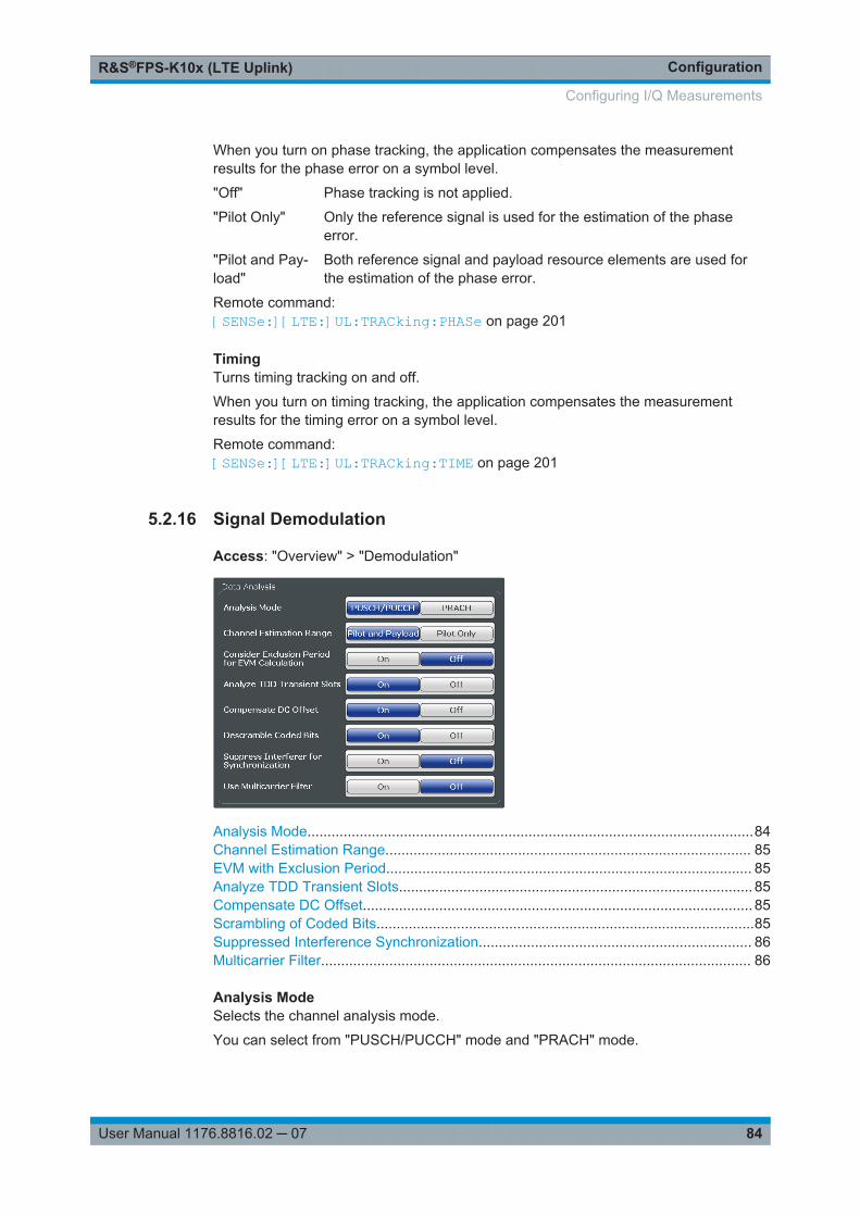
ConfigurationR&S®FPS-K10x (LTE Uplink)
84User Manual 1176.8816.02 ─ 07
When you turn on phase tracking, the application compensates the measurementresults for the phase error on a symbol level.
"Off" Phase tracking is not applied.
"Pilot Only" Only the reference signal is used for the estimation of the phaseerror.
"Pilot and Pay-load"
Both reference signal and payload resource elements are used forthe estimation of the phase error.
Remote command: [SENSe:][LTE:]UL:TRACking:PHASe on page 201
TimingTurns timing tracking on and off.
When you turn on timing tracking, the application compensates the measurementresults for the timing error on a symbol level.
Remote command: [SENSe:][LTE:]UL:TRACking:TIME on page 201
5.2.16 Signal Demodulation
Access: "Overview" > "Demodulation"
Analysis Mode...............................................................................................................84Channel Estimation Range........................................................................................... 85EVM with Exclusion Period........................................................................................... 85Analyze TDD Transient Slots........................................................................................ 85Compensate DC Offset................................................................................................. 85Scrambling of Coded Bits..............................................................................................85Suppressed Interference Synchronization.................................................................... 86Multicarrier Filter........................................................................................................... 86
Analysis ModeSelects the channel analysis mode.
You can select from "PUSCH/PUCCH" mode and "PRACH" mode.
Configuring I/Q Measurements
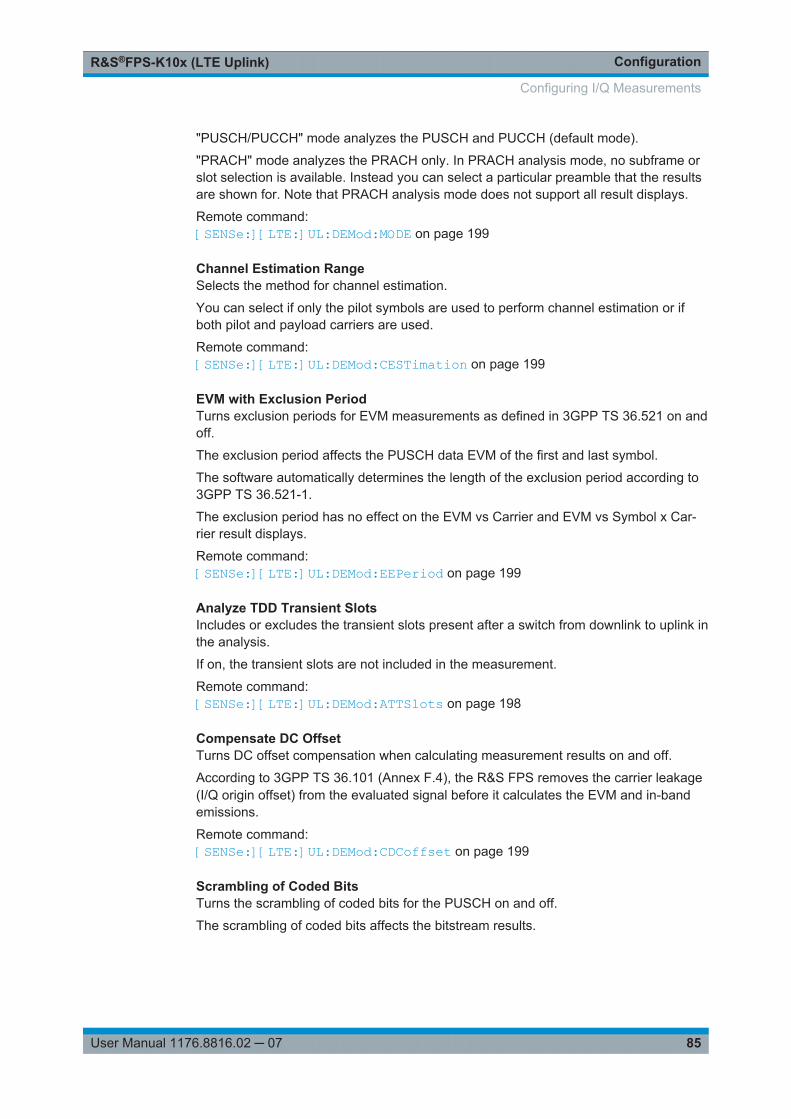
ConfigurationR&S®FPS-K10x (LTE Uplink)
85User Manual 1176.8816.02 ─ 07
"PUSCH/PUCCH" mode analyzes the PUSCH and PUCCH (default mode).
"PRACH" mode analyzes the PRACH only. In PRACH analysis mode, no subframe orslot selection is available. Instead you can select a particular preamble that the resultsare shown for. Note that PRACH analysis mode does not support all result displays.
Remote command: [SENSe:][LTE:]UL:DEMod:MODE on page 199
Channel Estimation RangeSelects the method for channel estimation.
You can select if only the pilot symbols are used to perform channel estimation or ifboth pilot and payload carriers are used.
Remote command: [SENSe:][LTE:]UL:DEMod:CESTimation on page 199
EVM with Exclusion PeriodTurns exclusion periods for EVM measurements as defined in 3GPP TS 36.521 on andoff.
The exclusion period affects the PUSCH data EVM of the first and last symbol.
The software automatically determines the length of the exclusion period according to3GPP TS 36.521-1.
The exclusion period has no effect on the EVM vs Carrier and EVM vs Symbol x Car-rier result displays.
Remote command: [SENSe:][LTE:]UL:DEMod:EEPeriod on page 199
Analyze TDD Transient SlotsIncludes or excludes the transient slots present after a switch from downlink to uplink inthe analysis.
If on, the transient slots are not included in the measurement.
Remote command: [SENSe:][LTE:]UL:DEMod:ATTSlots on page 198
Compensate DC OffsetTurns DC offset compensation when calculating measurement results on and off.
According to 3GPP TS 36.101 (Annex F.4), the R&S FPS removes the carrier leakage(I/Q origin offset) from the evaluated signal before it calculates the EVM and in-bandemissions.
Remote command: [SENSe:][LTE:]UL:DEMod:CDCoffset on page 199
Scrambling of Coded BitsTurns the scrambling of coded bits for the PUSCH on and off.
The scrambling of coded bits affects the bitstream results.
Configuring I/Q Measurements
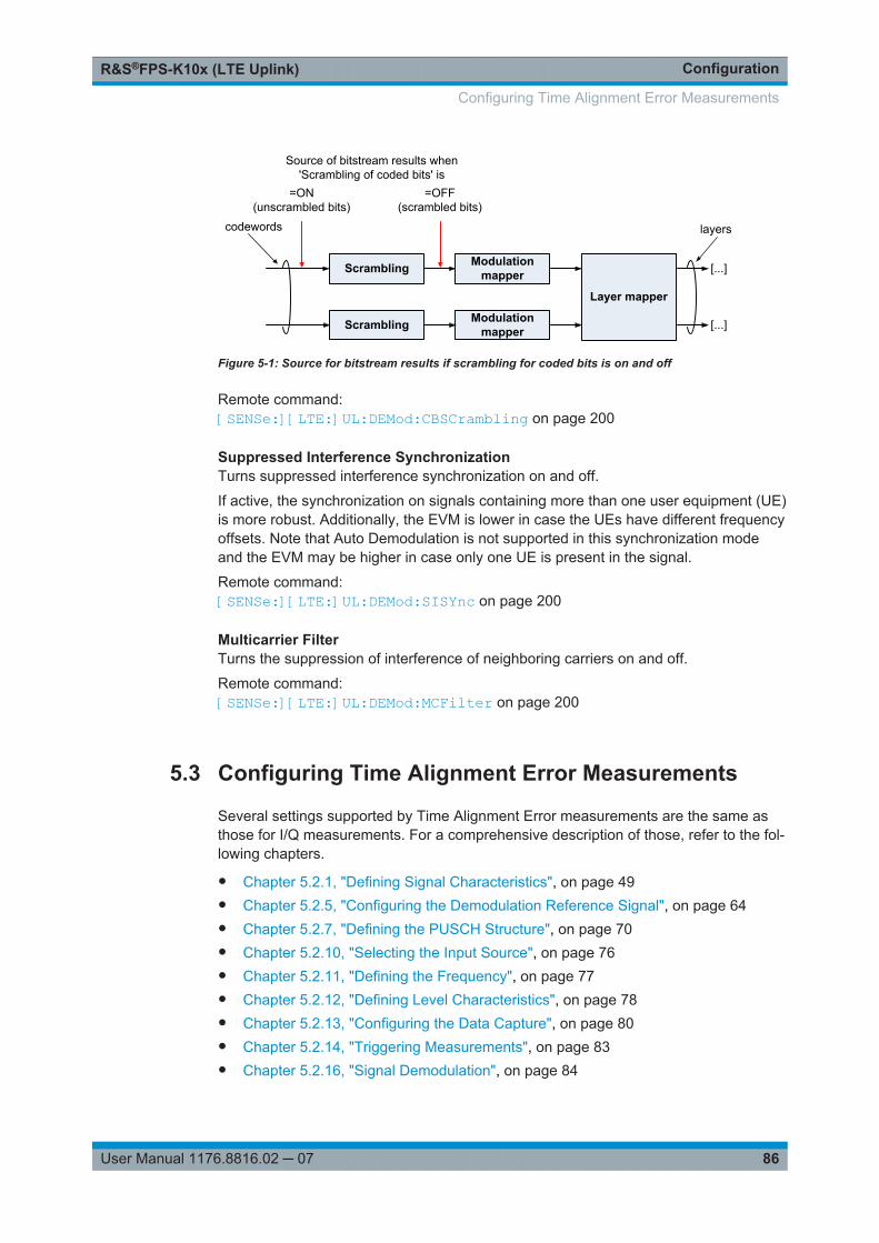
ConfigurationR&S®FPS-K10x (LTE Uplink)
86User Manual 1176.8816.02 ─ 07
Scrambling Modulation mapper
Modulation mapper
codewords
Layer mapper
[...]
[...]
layers
=ON(unscrambled bits)
=OFF(scrambled bits)
Source of bitstream results when 'Scrambling of coded bits' is
Scrambling
Figure 5-1: Source for bitstream results if scrambling for coded bits is on and off
Remote command: [SENSe:][LTE:]UL:DEMod:CBSCrambling on page 200
Suppressed Interference SynchronizationTurns suppressed interference synchronization on and off.
If active, the synchronization on signals containing more than one user equipment (UE)is more robust. Additionally, the EVM is lower in case the UEs have different frequencyoffsets. Note that Auto Demodulation is not supported in this synchronization modeand the EVM may be higher in case only one UE is present in the signal.
Remote command: [SENSe:][LTE:]UL:DEMod:SISYnc on page 200
Multicarrier FilterTurns the suppression of interference of neighboring carriers on and off.
Remote command: [SENSe:][LTE:]UL:DEMod:MCFilter on page 200
5.3 Configuring Time Alignment Error Measurements
Several settings supported by Time Alignment Error measurements are the same asthose for I/Q measurements. For a comprehensive description of those, refer to the fol-lowing chapters.
● Chapter 5.2.1, "Defining Signal Characteristics", on page 49● Chapter 5.2.5, "Configuring the Demodulation Reference Signal", on page 64● Chapter 5.2.7, "Defining the PUSCH Structure", on page 70● Chapter 5.2.10, "Selecting the Input Source", on page 76● Chapter 5.2.11, "Defining the Frequency", on page 77● Chapter 5.2.12, "Defining Level Characteristics", on page 78● Chapter 5.2.13, "Configuring the Data Capture", on page 80● Chapter 5.2.14, "Triggering Measurements", on page 83● Chapter 5.2.16, "Signal Demodulation", on page 84
Configuring Time Alignment Error Measurements
ConfigurationR&S®FPS-K10x (LTE Uplink)
87User Manual 1176.8816.02 ─ 07
For more information about configuring carrier aggregation see "Carrier Aggregation"on page 51.
5.4 Configuring Frequency Sweep Measurements
After starting one of the frequency sweep measurements, the application automaticallyloads the configuration required by measurements according to the 3GPP standard:the spectral mask as defined in the 3GPP standard for SEM measurements and thechannel configuration defined in the standard for the ACLR measurement.
If you need a different measurement configuration, you can change all parameters asrequired. Except for the dialog box decribed below, the measurement configurationmenus for the frequency sweep measurements are the same as in the Spectrum appli-cation.
Please refer to the User Manual of the R&S FPS for a detailed description on how toconfigure ACLR and SEM measurements.
● ACLR Signal Description.........................................................................................87● SEM Signal Description.......................................................................................... 88● MC ACLR Signal Description..................................................................................88
5.4.1 ACLR Signal Description
Access: MEAS CONFIG > "Signal Description"
The signal description for ACLR measurements contains settings to describe generalphysical characteristics of the signal you are measuring.
For more information on the "LTE Mode", "Test Model" and "Channel Bandwidth" see"Selecting the LTE mode" on page 50, "Using Test Scenarios" on page 50 and "Chan-nel Bandwidth / Number of Resource Blocks" on page 54.
All other settings available for the ACLR measurement are the same as in the spec-trum application. For more information, refer to the user manual of the R&S FPS.
Assumed Adjacent Channel Carrier..............................................................................87
Assumed Adjacent Channel CarrierSelects the assumed adjacent channel carrier for the ACLR measurement.
The supported types are EUTRA of same bandwidth, 1.28 Mcps UTRA, 3.84 McpsUTRA and 7.68 Mcps UTRA.
Note that not all combinations of LTE channel bandwidth settings and assumed adja-cent channel carrier settings are defined in the 3GPP standard.
Remote command: [SENSe:]POWer:ACHannel:AACHannel on page 204
Configuring Frequency Sweep Measurements
ConfigurationR&S®FPS-K10x (LTE Uplink)
88User Manual 1176.8816.02 ─ 07
5.4.2 SEM Signal Description
The signal description for SEM measurements contains settings to describe generalphysical characteristics of the signal you are measuring.
Access: "Overview" > "Signal Description"
For more information on the "LTE Mode", "Test Model", "Channel Bandwidth" and"Cyclic Prefix" see "Selecting the LTE mode" on page 50, "Using Test Scenarios"on page 50, "Channel Bandwidth / Number of Resource Blocks" on page 54 and"Cyclic Prefix" on page 54.
All other settings available for the SEM measurement are the same as in the spectrumapplication. For more information, refer to the user manual of the R&S FPS.
SEM Requirement.........................................................................................................88
SEM RequirementSelects the type of spectrum emission mask used for the Out of Band emission mea-surement.
The software supports general and specific (additional) spectrum emission masks. Thespecific spectrum emission masks contain additional SEM requirements. The addi-tional requirement masks to use for the measurement depend on the network signaledvalue "NS_03", "NS_04", "NS_06" or "NS_07".
If "NS_06" or "NS_07" is indicated in the cell, use SEM requirement "NS_06_07".
Remote command: [SENSe:]POWer:SEM:UL:REQuirement on page 204
5.4.3 MC ACLR Signal Description
Access: "Overview" > "Signal Description" > "Physical Settings CC<x>" / "Carrier Con-figuration"
You can configure the characteristics of the carriers in the "Carrier Configuration" tab.
Note: the "Carrier Configuration" button in the "Physical Settings" tab also opens the"Carrier Configuration" tab.
The signal description for MC ACLR measurements contain settings to describe gen-eral physical characteristics of the signal you are measuring.
Configuring Frequency Sweep Measurements
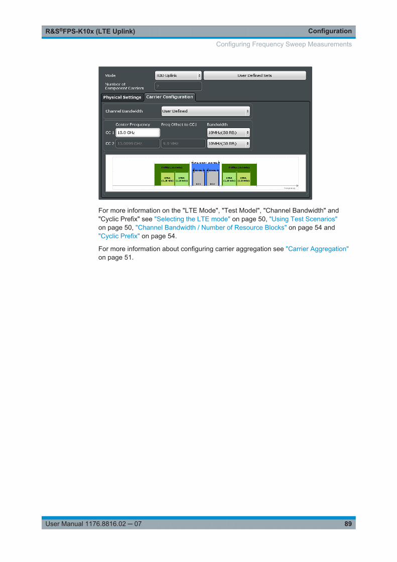
ConfigurationR&S®FPS-K10x (LTE Uplink)
89User Manual 1176.8816.02 ─ 07
For more information on the "LTE Mode", "Test Model", "Channel Bandwidth" and"Cyclic Prefix" see "Selecting the LTE mode" on page 50, "Using Test Scenarios"on page 50, "Channel Bandwidth / Number of Resource Blocks" on page 54 and"Cyclic Prefix" on page 54.
For more information about configuring carrier aggregation see "Carrier Aggregation"on page 51.
Configuring Frequency Sweep Measurements
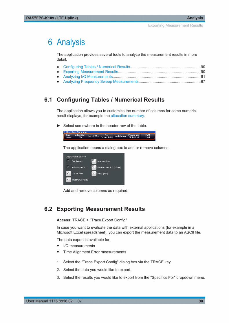
AnalysisR&S®FPS-K10x (LTE Uplink)
90User Manual 1176.8816.02 ─ 07
6 AnalysisThe application provides several tools to analyze the measurement results in moredetail.
● Configuring Tables / Numerical Results..................................................................90● Exporting Measurement Results.............................................................................90● Analyzing I/Q Measurements..................................................................................91● Analyzing Frequency Sweep Measurements..........................................................97
6.1 Configuring Tables / Numerical Results
The application allows you to customize the number of columns for some numericresult displays, for example the allocation summary.
► Select somewhere in the header row of the table.
The application opens a dialog box to add or remove columns.
Add and remove columns as required.
6.2 Exporting Measurement Results
Access: TRACE > "Trace Export Config"
In case you want to evaluate the data with external applications (for example in aMicrosoft Excel spreadsheet), you can export the measurement data to an ASCII file.
The data export is available for:● I/Q measurements● Time Alignment Error measurements
1. Select the "Trace Export Config" dialog box via the TRACE key.
2. Select the data you would like to export.
3. Select the results you would like to export from the "Specifics For" dropdown menu.
Exporting Measurement Results
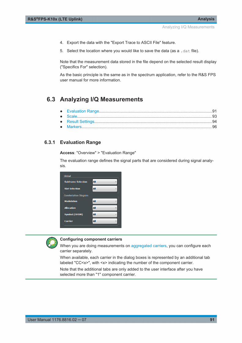
AnalysisR&S®FPS-K10x (LTE Uplink)
91User Manual 1176.8816.02 ─ 07
4. Export the data with the "Export Trace to ASCII File" feature.
5. Select the location where you would like to save the data (as a .dat file).
Note that the measurement data stored in the file depend on the selected result display("Specifics For" selection).
As the basic principle is the same as in the spectrum application, refer to the R&S FPSuser manual for more information.
6.3 Analyzing I/Q Measurements
● Evaluation Range....................................................................................................91● Scale....................................................................................................................... 93● Result Settings........................................................................................................94● Markers................................................................................................................... 96
6.3.1 Evaluation Range
Access: "Overview" > "Evaluation Range"
The evaluation range defines the signal parts that are considered during signal analy-sis.
Configuring component carriersWhen you are doing measurements on aggregated carriers, you can configure eachcarrier separately.When available, each carrier in the dialog boxes is represented by an additional tablabeled "CC<x>", with <x> indicating the number of the component carrier.Note that the additional tabs are only added to the user interface after you haveselected more than "1" component carrier.
Analyzing I/Q Measurements
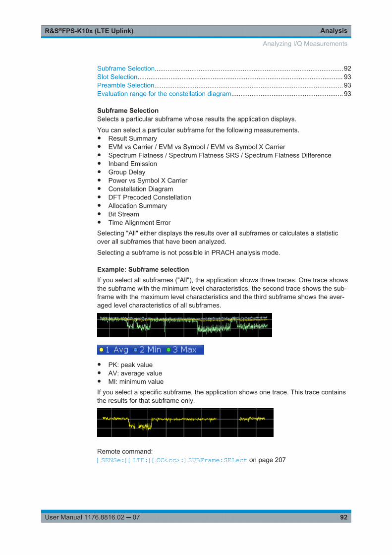
AnalysisR&S®FPS-K10x (LTE Uplink)
92User Manual 1176.8816.02 ─ 07
Subframe Selection.......................................................................................................92Slot Selection................................................................................................................ 93Preamble Selection....................................................................................................... 93Evaluation range for the constellation diagram............................................................. 93
Subframe SelectionSelects a particular subframe whose results the application displays.
You can select a particular subframe for the following measurements.● Result Summary● EVM vs Carrier / EVM vs Symbol / EVM vs Symbol X Carrier● Spectrum Flatness / Spectrum Flatness SRS / Spectrum Flatness Difference● Inband Emission● Group Delay● Power vs Symbol X Carrier● Constellation Diagram● DFT Precoded Constellation● Allocation Summary● Bit Stream● Time Alignment ErrorSelecting "All" either displays the results over all subframes or calculates a statisticover all subframes that have been analyzed.
Selecting a subframe is not possible in PRACH analysis mode.
Example: Subframe selectionIf you select all subframes ("All"), the application shows three traces. One trace showsthe subframe with the minimum level characteristics, the second trace shows the sub-frame with the maximum level characteristics and the third subframe shows the aver-aged level characteristics of all subframes.
● PK: peak value● AV: average value● MI: minimum valueIf you select a specific subframe, the application shows one trace. This trace containsthe results for that subframe only.
Remote command: [SENSe:][LTE:][CC<cc>:]SUBFrame:SELect on page 207
Analyzing I/Q Measurements
AnalysisR&S®FPS-K10x (LTE Uplink)
93User Manual 1176.8816.02 ─ 07
Slot SelectionSelects a single slot whose results the application displays. Alternatively, you can dis-play the results over all slots.
You can select a single slot for the following measurements.● Result Summary● EVM vs Carrier / EVM vs Symbol / EVM vs Symbol X Carrier● Inband Emission● Spectrum Flatness / Spectrum Flatness Difference● Group Delay● Power vs Symbol X Carrier● Constellation DiagramIn PRACH analysis mode, you cannot select a particular slot.
Remote command: [SENSe:][LTE:][CC<cc>:]SLOT:SELect on page 207
Preamble SelectionSelects a particular preamble for measurements that analyze individual preambles.
Selecting preambles is available in PRACH analysis mode.
Remote command: [SENSe:][LTE:][CC<cc>:]PREamble:SELect on page 206
Evaluation range for the constellation diagramThe "Evaluation Range" dialog box defines the type of constellation points that are dis-played in the "Constellation Diagram".
By default the application displays all constellation points of the data that have beenevaluated. However, you can filter the results by several aspects.● Modulation
Filters the results to include only the selected type of modulation.● Allocation
Filters the results to include only a certain type of allocation.● Symbol (OFDM)
Filters the results to include only a certain OFDM symbol.● Carrier
Filters the results to include only a certain subcarrier.The result display is updated when you make the changes.
Note that the constellation selection is applied to all windows in split screen mode if thewindows contain constellation diagrams.
Remote command: Modulation: [SENSe:][LTE:][CC<cc>:]MODulation:SELect on page 206Allocation: [SENSe:][LTE:][CC<cc>:]ALLocation:SELect on page 205Symbol: [SENSe:][LTE:][CC<cc>:]SYMBol:SELect on page 208Carrier: [SENSe:][LTE:][CC<cc>:]CARRier:SELect on page 206
6.3.2 Scale
Access: "Overview" > "Analysis" > "Scale"
Analyzing I/Q Measurements

AnalysisR&S®FPS-K10x (LTE Uplink)
94User Manual 1176.8816.02 ─ 07
Scaling settings define the diagram scale.
Y-Axis Scale..................................................................................................................94
Y-Axis ScaleThe y-axis scaling determines the vertical resolution of the measurement results. Thescaling you select always applies to the currently active screen and the correspondingresult display.
Usually, the best way to view the results is if they fit ideally in the diagram area anddisplay the complete trace. This is the way the application scales the y-axis if you areusing the automatic scale function.
But it can become necessary to see a more detailed version of the results. In that case,turn on fixed scaling for the y-axis by defining the minimum and maximum values dis-played on the vertical axis. Possible values and units depend on the result display youwant to adjust the scale of.
You can restore the default scale at any time with "Restore Scale".
Tip:Alternatively, you can scale the windows in the "Auto Set" menu. In addition to scalingthe window currently in focus ("Auto Scale Window"), there you can scale all windowsat the same time ("Auto Scale All").
Remote command: DISPlay[:WINDow<n>][:SUBWindow<w>]:TRACe<t>:Y[:SCALe]:AUTOon page 208DISPlay[:WINDow<n>][:SUBWindow<w>]:TRACe<t>:Y[:SCALe]:MAXimumon page 209DISPlay[:WINDow<n>][:SUBWindow<w>]:TRACe<t>:Y[:SCALe]:MINimumon page 209
6.3.3 Result Settings
Access: "Overview" > "Analysis" > "Result Settings"
Result settings define the way certain measurement results are displayed.
EVM Unit....................................................................................................................... 95Bit Stream Format......................................................................................................... 95Carrier Axes.................................................................................................................. 95Marker Coupling............................................................................................................95Subwindow Coupling.....................................................................................................96
Analyzing I/Q Measurements
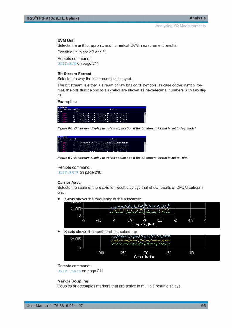
AnalysisR&S®FPS-K10x (LTE Uplink)
95User Manual 1176.8816.02 ─ 07
EVM UnitSelects the unit for graphic and numerical EVM measurement results.
Possible units are dB and %.
Remote command: UNIT:EVM on page 211
Bit Stream FormatSelects the way the bit stream is displayed.
The bit stream is either a stream of raw bits or of symbols. In case of the symbol for-mat, the bits that belong to a symbol are shown as hexadecimal numbers with two dig-its.
Examples:
Figure 6-1: Bit stream display in uplink application if the bit stream format is set to "symbols"
Figure 6-2: Bit stream display in uplink application if the bit stream format is set to "bits"
Remote command: UNIT:BSTR on page 210
Carrier AxesSelects the scale of the x-axis for result displays that show results of OFDM subcarri-ers.● X-axis shows the frequency of the subcarrier
● X-axis shows the number of the subcarrier
Remote command: UNIT:CAXes on page 211
Marker CouplingCouples or decouples markers that are active in multiple result displays.
Analyzing I/Q Measurements
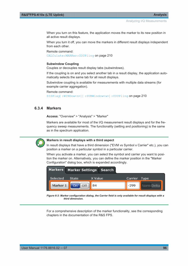
AnalysisR&S®FPS-K10x (LTE Uplink)
96User Manual 1176.8816.02 ─ 07
When you turn on this feature, the application moves the marker to its new position inall active result displays.
When you turn it off, you can move the markers in different result displays independentfrom each other.
Remote command: CALCulate:MARKer:COUPling on page 210
Subwindow CouplingCouples or decouples result display tabs (subwindows).
If the coupling is on and you select another tab in a result display, the application auto-matically selects the same tab for all result displays.
Subwindow coupling is available for measurements with multiple data streams (forexample carrier aggregation).
Remote command: DISPlay[:WINDow<n>][:SUBWindow<w>]:COUPling on page 210
6.3.4 Markers
Access: "Overview" > "Analysis" > "Marker"
Markers are available for most of the I/Q measurement result displays and for the fre-quency sweep measurements. The functionality (setting and positioning) is the sameas in the spectrum application.
Markers in result displays with a third aspectIn result displays that have a third dimension ("EVM vs Symbol x Carrier" etc.), you canposition a marker on a particular symbol in a particular carrier.When you activate a marker, you can select the symbol and carrier you want to posi-tion the marker on. Alternatively, you can define the marker position in the "MarkerConfiguration" dialog box, which is expanded accordingly.
Figure 6-3: Marker configuration dialog, the Carrier field is only available for result displays with athird dimension.
For a comprehensive description of the marker functionality, see the correspondingchapters in the documentation of the R&S FPS.
Analyzing I/Q Measurements
AnalysisR&S®FPS-K10x (LTE Uplink)
97User Manual 1176.8816.02 ─ 07
6.4 Analyzing Frequency Sweep Measurements
The LTE application supports the same functionality to analyze the results of frequencysweep measurements (for example the ACLR) as the R&S FPS base unit does forthose measurements.
Refer to the user manual of the R&S FPS for a detailed description on how to analyzethese measurements.
Analyzing Frequency Sweep Measurements
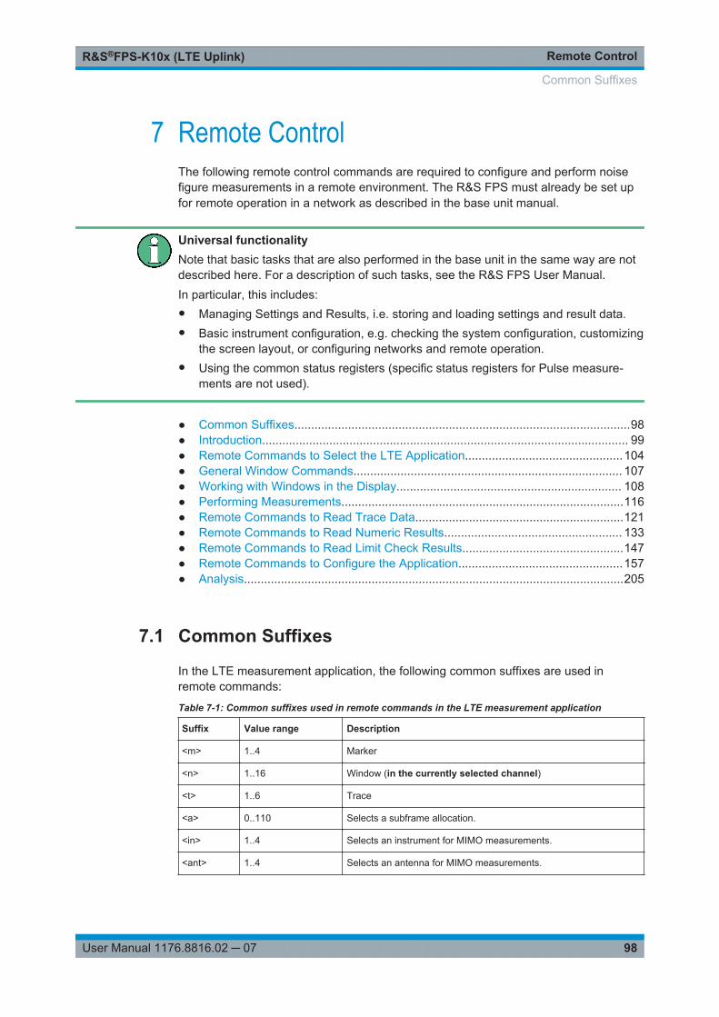
Remote ControlR&S®FPS-K10x (LTE Uplink)
98User Manual 1176.8816.02 ─ 07
7 Remote ControlThe following remote control commands are required to configure and perform noisefigure measurements in a remote environment. The R&S FPS must already be set upfor remote operation in a network as described in the base unit manual.
Universal functionalityNote that basic tasks that are also performed in the base unit in the same way are notdescribed here. For a description of such tasks, see the R&S FPS User Manual.In particular, this includes:● Managing Settings and Results, i.e. storing and loading settings and result data.● Basic instrument configuration, e.g. checking the system configuration, customizing
the screen layout, or configuring networks and remote operation.● Using the common status registers (specific status registers for Pulse measure-
ments are not used).
● Common Suffixes....................................................................................................98● Introduction............................................................................................................. 99● Remote Commands to Select the LTE Application...............................................104● General Window Commands................................................................................ 107● Working with Windows in the Display................................................................... 108● Performing Measurements....................................................................................116● Remote Commands to Read Trace Data..............................................................121● Remote Commands to Read Numeric Results..................................................... 133● Remote Commands to Read Limit Check Results................................................147● Remote Commands to Configure the Application.................................................157● Analysis.................................................................................................................205
7.1 Common Suffixes
In the LTE measurement application, the following common suffixes are used inremote commands:
Table 7-1: Common suffixes used in remote commands in the LTE measurement application
Suffix Value range Description
<m> 1..4 Marker
<n> 1..16 Window (in the currently selected channel)
<t> 1..6 Trace
<a> 0..110 Selects a subframe allocation.
<in> 1..4 Selects an instrument for MIMO measurements.
<ant> 1..4 Selects an antenna for MIMO measurements.
Common Suffixes
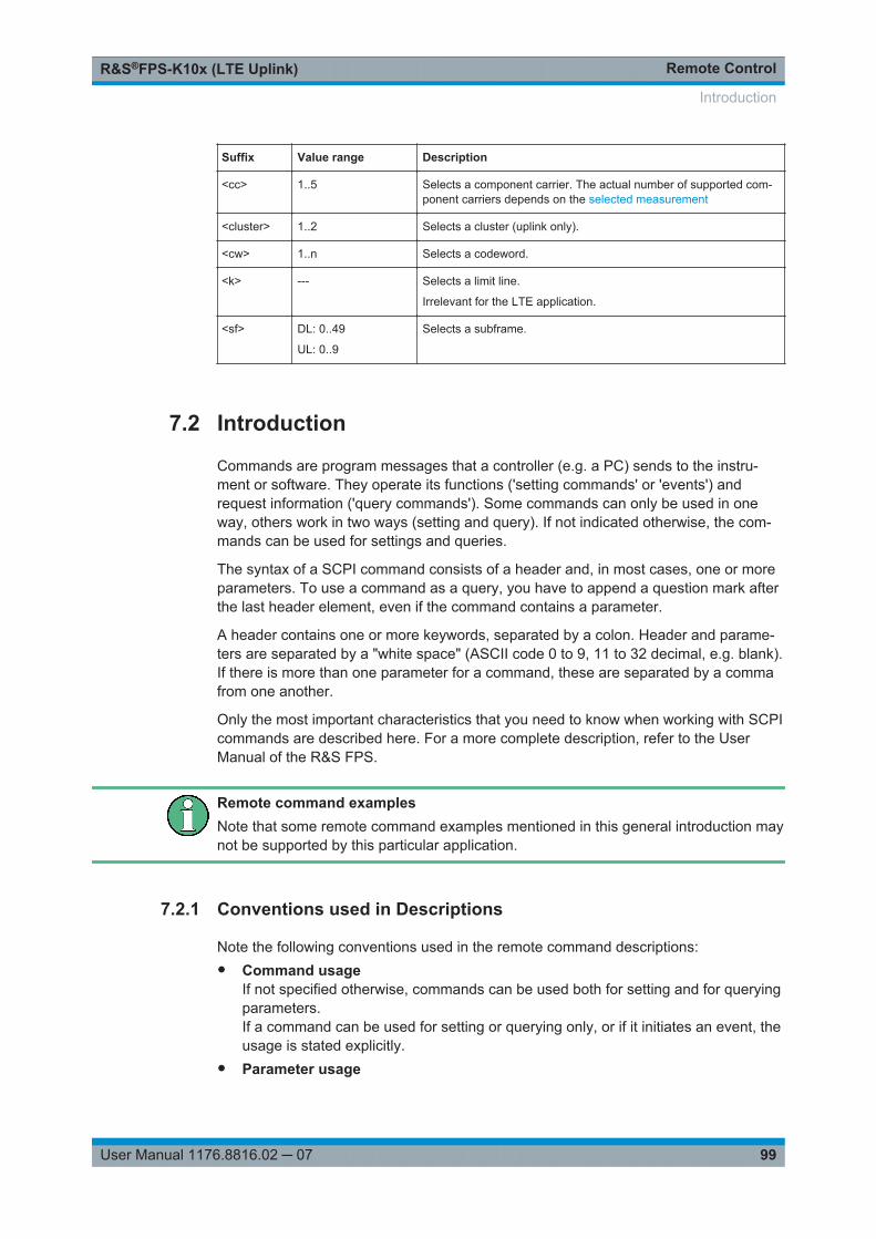
Remote ControlR&S®FPS-K10x (LTE Uplink)
99User Manual 1176.8816.02 ─ 07
Suffix Value range Description
<cc> 1..5 Selects a component carrier. The actual number of supported com-ponent carriers depends on the selected measurement
<cluster> 1..2 Selects a cluster (uplink only).
<cw> 1..n Selects a codeword.
<k> --- Selects a limit line.
Irrelevant for the LTE application.
<sf> DL: 0..49
UL: 0..9
Selects a subframe.
7.2 Introduction
Commands are program messages that a controller (e.g. a PC) sends to the instru-ment or software. They operate its functions ('setting commands' or 'events') andrequest information ('query commands'). Some commands can only be used in oneway, others work in two ways (setting and query). If not indicated otherwise, the com-mands can be used for settings and queries.
The syntax of a SCPI command consists of a header and, in most cases, one or moreparameters. To use a command as a query, you have to append a question mark afterthe last header element, even if the command contains a parameter.
A header contains one or more keywords, separated by a colon. Header and parame-ters are separated by a "white space" (ASCII code 0 to 9, 11 to 32 decimal, e.g. blank).If there is more than one parameter for a command, these are separated by a commafrom one another.
Only the most important characteristics that you need to know when working with SCPIcommands are described here. For a more complete description, refer to the UserManual of the R&S FPS.
Remote command examplesNote that some remote command examples mentioned in this general introduction maynot be supported by this particular application.
7.2.1 Conventions used in Descriptions
Note the following conventions used in the remote command descriptions:● Command usage
If not specified otherwise, commands can be used both for setting and for queryingparameters.If a command can be used for setting or querying only, or if it initiates an event, theusage is stated explicitly.
● Parameter usage
Introduction
Remote ControlR&S®FPS-K10x (LTE Uplink)
100User Manual 1176.8816.02 ─ 07
If not specified otherwise, a parameter can be used to set a value and it is theresult of a query.Parameters required only for setting are indicated as Setting parameters.Parameters required only to refine a query are indicated as Query parameters.Parameters that are only returned as the result of a query are indicated as Returnvalues.
● ConformityCommands that are taken from the SCPI standard are indicated as SCPI con-firmed. All commands used by the R&S FPS follow the SCPI syntax rules.
● Asynchronous commandsA command which does not automatically finish executing before the next com-mand starts executing (overlapping command) is indicated as an Asynchronouscommand.
● Reset values (*RST)Default parameter values that are used directly after resetting the instrument (*RSTcommand) are indicated as *RST values, if available.
● Default unitThis is the unit used for numeric values if no other unit is provided with the parame-ter.
● Manual operationIf the result of a remote command can also be achieved in manual operation, a linkto the description is inserted.
7.2.2 Long and Short Form
The keywords have a long and a short form. You can use either the long or the shortform, but no other abbreviations of the keywords.
The short form is emphasized in upper case letters. Note however, that this emphasisonly serves the purpose to distinguish the short from the long form in the manual. Forthe instrument, the case does not matter.
Example: SENSe:FREQuency:CENTer is the same as SENS:FREQ:CENT.
7.2.3 Numeric Suffixes
Some keywords have a numeric suffix if the command can be applied to multipleinstances of an object. In that case, the suffix selects a particular instance (e.g. a mea-surement window).
Numeric suffixes are indicated by angular brackets (<n>) next to the keyword.
If you don't quote a suffix for keywords that support one, a 1 is assumed.
Introduction
Remote ControlR&S®FPS-K10x (LTE Uplink)
101User Manual 1176.8816.02 ─ 07
Example: DISPlay[:WINDow<1...4>]:ZOOM:STATe enables the zoom in a particular mea-surement window, selected by the suffix at WINDow.
DISPlay:WINDow4:ZOOM:STATe ON refers to window 4.
7.2.4 Optional Keywords
Some keywords are optional and are only part of the syntax because of SCPI compli-ance. You can include them in the header or not.
Note that if an optional keyword has a numeric suffix and you need to use the suffix,you have to include the optional keyword. Otherwise, the suffix of the missing keywordis assumed to be the value 1.
Optional keywords are emphasized with square brackets.
Example: Without a numeric suffix in the optional keyword:[SENSe:]FREQuency:CENTer is the same as FREQuency:CENTerWith a numeric suffix in the optional keyword:DISPlay[:WINDow<1...4>]:ZOOM:STATeDISPlay:ZOOM:STATe ON enables the zoom in window 1 (no suffix).
DISPlay:WINDow4:ZOOM:STATe ON enables the zoom in window 4.
7.2.5 Alternative Keywords
A vertical stroke indicates alternatives for a specific keyword. You can use both key-words to the same effect.
Example: [SENSe:]BANDwidth|BWIDth[:RESolution]In the short form without optional keywords, BAND 1MHZ would have the same effectas BWID 1MHZ.
7.2.6 SCPI Parameters
Many commands feature one or more parameters.
If a command supports more than one parameter, these are separated by a comma.
Example: LAYout:ADD:WINDow Spectrum,LEFT,MTABle
Parameters may have different forms of values.
Introduction
Remote ControlR&S®FPS-K10x (LTE Uplink)
102User Manual 1176.8816.02 ─ 07
● Numeric Values.....................................................................................................102● Boolean.................................................................................................................103● Character Data......................................................................................................103● Character Strings.................................................................................................. 103● Block Data.............................................................................................................103
7.2.6.1 Numeric Values
Numeric values can be entered in any form, i.e. with sign, decimal point or exponent. Incase of physical quantities, you can also add the unit. If the unit is missing, the com-mand uses the basic unit.
Example: With unit: SENSe:FREQuency:CENTer 1GHZWithout unit: SENSe:FREQuency:CENTer 1E9 would also set a frequency of 1 GHz.
Values exceeding the resolution of the instrument are rounded up or down.
If the number you have entered is not supported (e.g. in case of discrete steps), thecommand returns an error.
Instead of a number, you can also set numeric values with a text parameter in specialcases.
● MIN/MAXDefines the minimum or maximum numeric value that is supported.
● DEFDefines the default value.
● UP/DOWNIncreases or decreases the numeric value by one step. The step size depends onthe setting. In some cases you can customize the step size with a correspondingcommand.
Querying numeric values
When you query numeric values, the system returns a number. In case of physicalquantities, it applies the basic unit (e.g. Hz in case of frequencies). The number of dig-its after the decimal point depends on the type of numeric value.
Example: Setting: SENSe:FREQuency:CENTer 1GHZQuery: SENSe:FREQuency:CENTer? would return 1E9
In some cases, numeric values may be returned as text.
● INF/NINFInfinity or negative infinity. Represents the numeric values 9.9E37 or -9.9E37.
● NAN
Introduction
Remote ControlR&S®FPS-K10x (LTE Uplink)
103User Manual 1176.8816.02 ─ 07
Not a number. Represents the numeric value 9.91E37. NAN is returned in case oferrors.
7.2.6.2 Boolean
Boolean parameters represent two states. The "ON" state (logically true) is represen-ted by "ON" or a numeric value 1. The "OFF" state (logically untrue) is represented by"OFF" or the numeric value 0.
Querying Boolean parameters
When you query Boolean parameters, the system returns either the value 1 ("ON") orthe value 0 ("OFF").
Example: Setting: DISPlay:WINDow:ZOOM:STATe ONQuery: DISPlay:WINDow:ZOOM:STATe? would return 1
7.2.6.3 Character Data
Character data follows the syntactic rules of keywords. You can enter text using a shortor a long form. For more information see Chapter 7.2.2, "Long and Short Form",on page 100.
Querying text parameters
When you query text parameters, the system returns its short form.
Example: Setting: SENSe:BANDwidth:RESolution:TYPE NORMalQuery: SENSe:BANDwidth:RESolution:TYPE? would return NORM
7.2.6.4 Character Strings
Strings are alphanumeric characters. They have to be in straight quotation marks. Youcan use a single quotation mark ( ' ) or a double quotation mark ( " ).
Example: INSTRument:DELete 'Spectrum'
7.2.6.5 Block Data
Block data is a format which is suitable for the transmission of large amounts of data.
The ASCII character # introduces the data block. The next number indicates how manyof the following digits describe the length of the data block. In the example the 4 follow-ing digits indicate the length to be 5168 bytes. The data bytes follow. During the trans-mission of these data bytes all end or other control signs are ignored until all bytes are
Introduction
Remote ControlR&S®FPS-K10x (LTE Uplink)
104User Manual 1176.8816.02 ─ 07
transmitted. #0 specifies a data block of indefinite length. The use of the indefinite for-mat requires an NL^END message to terminate the data block. This format is usefulwhen the length of the transmission is not known or if speed or other considerationsprevent segmentation of the data into blocks of definite length.
7.3 Remote Commands to Select the LTE Application
INSTrument:CREate:DUPLicate...................................................................................... 104INSTrument:CREate[:NEW]............................................................................................ 104INSTrument:CREate:REPLace........................................................................................105INSTrument:DELete....................................................................................................... 105INSTrument:LIST?......................................................................................................... 105INSTrument:REName.....................................................................................................106INSTrument[:SELect]......................................................................................................107
INSTrument:CREate:DUPLicate
This command duplicates the currently selected channel, i.e creates a new channel ofthe same type and with the identical measurement settings. The name of the newchannel is the same as the copied channel, extended by a consecutive number (e.g."IQAnalyzer" -> "IQAnalyzer 2").
The channel to be duplicated must be selected first using the INST:SEL command.
This command is not available if the MSRA/MSRT Master channel is selected.
Example: INST:SEL 'IQAnalyzer'INST:CRE:DUPLDuplicates the channel named 'IQAnalyzer' and creates a newchannel named 'IQAnalyzer2'.
Usage: Event
INSTrument:CREate[:NEW] <ChannelType>, <ChannelName>
This command adds an additional channel.
The number of channels you can configure at the same time depends on availablememory.
Parameters:<ChannelType> Channel type of the new channel.
For a list of available channel types see INSTrument:LIST?on page 105.
<ChannelName> String containing the name of the channel. The channel name isdisplayed as the tab label for the channel.Note: If the specified name for a new channel already exists, thedefault name, extended by a sequential number, is used for thenew channel (see INSTrument:LIST? on page 105).
Remote Commands to Select the LTE Application
Remote ControlR&S®FPS-K10x (LTE Uplink)
105User Manual 1176.8816.02 ─ 07
Example: INST:CRE IQ, 'IQAnalyzer2'Adds an additional I/Q Analyzer channel named "IQAnalyzer2".
INSTrument:CREate:REPLace <ChannelName1>,<ChannelType>,<ChannelName2>
This command replaces a channel with another one.
Setting parameters: <ChannelName1> String containing the name of the channel you want to replace.
<ChannelType> Channel type of the new channel.For a list of available channel types see INSTrument:LIST?on page 105.
<ChannelName2> String containing the name of the new channel.Note: If the specified name for a new channel already exists, thedefault name, extended by a sequential number, is used for thenew channel (see INSTrument:LIST? on page 105).
Example: INST:CRE:REPL 'IQAnalyzer2',IQ,'IQAnalyzer'Replaces the channel named "IQAnalyzer2" by a new channel oftype "IQ Analyzer" named "IQAnalyzer".
Usage: Setting only
INSTrument:DELete <ChannelName>
This command deletes a channel.
If you delete the last channel, the default "Spectrum" channel is activated.
Parameters:<ChannelName> String containing the name of the channel you want to delete.
A channel must exist in order to be able delete it.
Example: INST:DEL 'IQAnalyzer4'Deletes the channel with the name 'IQAnalyzer4'.
Usage: Event
INSTrument:LIST?
This command queries all active channels. This is useful in order to obtain the namesof the existing channels, which are required in order to replace or delete the channels.
Return values: <ChannelType>,<ChannelName>
For each channel, the command returns the channel type andchannel name (see tables below).Tip: to change the channel name, use the INSTrument:REName command.
Remote Commands to Select the LTE Application
Remote ControlR&S®FPS-K10x (LTE Uplink)
106User Manual 1176.8816.02 ─ 07
Example: INST:LIST?Result for 3 channels:'ADEM','Analog Demod','IQ','IQAnalyzer','IQ','IQ Analyzer2'
Usage: Query only
Table 7-2: Available channel types and default channel names in Signal and Spectrum Analyzer mode
Application <ChannelType>Parameter
Default Channel Name*)
Spectrum SANALYZER Spectrum
1xEV-DO BTS (R&S FPS-K84) BDO 1xEV-DO BTS
1xEV-DO MS (R&S FPS-K85) MDO 1xEV-DO MS
3GPP FDD BTS (R&S FPS-K72) BWCD 3G FDD BTS
3GPP FDD UE (R&S FPS-K73) MWCD 3G FDD UE
Analog Demodulation (R&S FPS-K7) ADEM Analog Demod
cdma2000 BTS (R&S FPS-K82) BC2K CDMA2000 BTS
cdma2000 MS (R&S FPS-K83) MC2K CDMA2000 MS
GSM (R&S FPS-K10) GSM GSM
I/Q Analyzer IQ IQ Analyzer
LTE (R&S FPS-K10x) LTE LTE
NB-IoT (R&S FPS-K106) NIOT NB-IoT
Noise (R&S FPS-K30) NOISE Noise
Phase Noise (R&S FPS-K40) PNOISE Phase Noise
TD-SCDMA BTS (R&S FPS-K76) BTDS TD-SCDMA BTS
TD-SCDMA UE (R&S FPS-K77) MTDS TD-SCDMA UE
Verizon 5GTF Measurement Application(V5GTF, R&S FPS-K118)
V5GT V5GT
VSA (R&S FPS-K70) DDEM VSA
WLAN (R&S FPS-K91) WLAN WLAN
*) the default channel name is also listed in the table. If the specified name for a new channel alreadyexists, the default name, extended by a sequential number, is used for the new channel.
INSTrument:REName <ChannelName1>, <ChannelName2>
This command renames a channel.
Parameters:<ChannelName1> String containing the name of the channel you want to rename.
Remote Commands to Select the LTE Application
Remote ControlR&S®FPS-K10x (LTE Uplink)
107User Manual 1176.8816.02 ─ 07
<ChannelName2> String containing the new channel name.Note that you cannot assign an existing channel name to a newchannel; this will cause an error.
Example: INST:REN 'IQAnalyzer2','IQAnalyzer3'Renames the channel with the name 'IQAnalyzer2' to 'IQAna-lyzer3'.
Usage: Setting only
INSTrument[:SELect] <ChannelType>
This command selects a new measurement channel with the defined channel type.
Parameters:<ChannelType> LTE
LTE measurement channel
Example: //Select LTE applicationINST LTE
7.4 General Window Commands
The following commands are required to configure general window layout, independentof the application.
Note that the suffix <n> always refers to the window in the currently selected channel(see INSTrument[:SELect] on page 107 ).
DISPlay:FORMat........................................................................................................... 107DISPlay[:WINDow<n>]:SIZE........................................................................................... 108DISPlay[:WINDow<n>][:SUBWindow<w>]:SELect............................................................. 108
DISPlay:FORMat <Format>
This command determines which tab is displayed.
Parameters:<Format> SPLit
Displays the MultiView tab with an overview of all active chan-nelsSINGleDisplays the measurement channel that was previously focused.*RST: SING
Example: DISP:FORM SPL
General Window Commands

Remote ControlR&S®FPS-K10x (LTE Uplink)
108User Manual 1176.8816.02 ─ 07
DISPlay[:WINDow<n>]:SIZE <Size>
This command maximizes the size of the selected result display window temporarily.To change the size of several windows on the screen permanently, use the LAY:SPLcommand (see LAYout:SPLitter on page 113).
Suffix: <n>
.Window
Parameters:<Size> LARGe
Maximizes the selected window to full screen.Other windows are still active in the background.SMALlReduces the size of the selected window to its original size.If more than one measurement window was displayed originally,these are visible again.*RST: SMALl
Example: DISP:WIND2:SIZE LARG
DISPlay[:WINDow<n>][:SUBWindow<w>]:SELect
This command sets the focus on the selected result display window.
This window is then the active window.
For measurements with multiple results in subwindows, the command also selects thesubwindow. Use this command to select the (sub)window before querying trace data.
Suffix: <n>
.Window
<w> Subwindow
Example: //Put the focus on window 1DISP:WIND1:SEL
Example: //Put the focus on subwindow 2 in window 1DISP:WIND1:SUBW2:SEL
Usage: Event
7.5 Working with Windows in the Display
The following commands are required to change the evaluation type and rearrange thescreen layout for a channel as you do using the SmartGrid in manual operation. Sincethe available evaluation types depend on the selected application, some parametersfor the following commands also depend on the selected channel.
Working with Windows in the Display
Remote ControlR&S®FPS-K10x (LTE Uplink)
109User Manual 1176.8816.02 ─ 07
LAYout:ADD[:WINDow]?.................................................................................................109LAYout:CATalog[:WINDow]?...........................................................................................111LAYout:IDENtify[:WINDow]?............................................................................................111LAYout:MOVE[:WINDow]................................................................................................112LAYout:REMove[:WINDow].............................................................................................112LAYout:REPLace[:WINDow]............................................................................................113LAYout:SPLitter............................................................................................................. 113LAYout:WINDow<n>:ADD?.............................................................................................115LAYout:WINDow<n>:IDENtify?........................................................................................115LAYout:WINDow<n>:REMove......................................................................................... 116LAYout:WINDow<n>:REPLace........................................................................................116
LAYout:ADD[:WINDow]? <WindowName>,<Direction>,<WindowType>
This command adds a window to the display in the active channel.
This command is always used as a query so that you immediately obtain the name ofthe new window as a result.
To replace an existing window, use the LAYout:REPLace[:WINDow] command.
Note: Use this command to select a result display instead of CALCulate:FEED (stillsupported for compatibility reasons, but deprecated).
Query parameters: <WindowName> String containing the name of the existing window the new win-
dow is inserted next to.By default, the name of a window is the same as its index. Todetermine the name and index of all active windows, use theLAYout:CATalog[:WINDow]? query.
<Direction> LEFT | RIGHt | ABOVe | BELowDirection the new window is added relative to the existing win-dow.
<WindowType> text valueType of result display (evaluation method) you want to add.See the table below for available parameter values.
Return values: <NewWindowName> When adding a new window, the command returns its name (by
default the same as its number) as a result.
Example: LAY:ADD? '1',LEFT,MTABResult:'2'Adds a new window named '2' with a marker table to the left ofwindow 1.
Usage: Query only
Working with Windows in the Display
Remote ControlR&S®FPS-K10x (LTE Uplink)
110User Manual 1176.8816.02 ─ 07
Manual operation: See "Capture Buffer" on page 16See "EVM vs Carrier" on page 16See "EVM vs Symbol" on page 17See "EVM vs Subframe" on page 18See "Power Spectrum" on page 18See "Inband Emission" on page 19See "Spectrum Flatness" on page 19See "Spectrum Flatness SRS" on page 20See "Group Delay" on page 20See "Spectrum Flatness Difference" on page 21See "Constellation Diagram" on page 21See "CCDF" on page 21See "Allocation Summary" on page 22See "Bit Stream" on page 23See "EVM vs Symbol x Carrier" on page 24See "Power vs Symbol x Carrier" on page 24See "Result Summary" on page 24See " Marker Table " on page 27See "Time Alignment Error" on page 29See " Marker Peak List " on page 35
Table 7-3: <WindowType> parameter values for LTE uplink measurement application
Parameter value Window type
I/Q measurements
ASUM Allocation Summary
BSTR Bitstream
CBUF Capture Buffer
CCDF CCDF
CONS Constellation Diagram
EVCA EVM vs. Carrier
EVSU EVM vs. Subframe
EVSY EVM vs. Symbol
EVSC EVM vs. Symbol X Carrier
GDEL Group Delay
IE Inband Emission
IEA Inband Emission All
MTAB Marker Table
PSPE Power Spectrum
PVSC Power vs. Symbol X Carrier
RSUM Result Summary
SFD Spectrum Flatness Difference
Working with Windows in the Display
Remote ControlR&S®FPS-K10x (LTE Uplink)
111User Manual 1176.8816.02 ─ 07
Parameter value Window type
SFL Spectrum Flatness
SFSR Spectrum Flatness SRS
Time alignment error
CBUF Capture Buffer
MTAB Marker Table
PSPE Power Spectrum
TAL Time Alignment Error
ACLR and SEM measurements
DIAG Diagram
PEAK Peak List
MTAB Marker Table
RSUM Result Summary
LAYout:CATalog[:WINDow]?
This command queries the name and index of all active windows in the active channelfrom top left to bottom right. The result is a comma-separated list of values for eachwindow, with the syntax:
<WindowName_1>,<WindowIndex_1>..<WindowName_n>,<WindowIndex_n>
Return values: <WindowName> string
Name of the window.In the default state, the name of the window is its index.
<WindowIndex> numeric valueIndex of the window.
Example: LAY:CAT?Result:'2',2,'1',1Two windows are displayed, named '2' (at the top or left), and '1'(at the bottom or right).
Usage: Query only
LAYout:IDENtify[:WINDow]? <WindowName>
This command queries the index of a particular display window in the active channel.
Note: to query the name of a particular window, use the LAYout:WINDow<n>:IDENtify? query.
Working with Windows in the Display
Remote ControlR&S®FPS-K10x (LTE Uplink)
112User Manual 1176.8816.02 ─ 07
Query parameters: <WindowName> String containing the name of a window.
Return values: <WindowIndex> Index number of the window.
Example: LAY:WIND:IDEN? '2'Queries the index of the result display named '2'.Response:2
Usage: Query only
LAYout:MOVE[:WINDow] <arg0>, <arg1>, <arg2>
Setting parameters: <arg0> String containing the name of an existing window that is to be
moved.By default, the name of a window is the same as its index. Todetermine the name and index of all active windows in the activechannel, use the LAYout:CATalog[:WINDow]? query.
<arg1> String containing the name of an existing window the selectedwindow is placed next to or replaces.By default, the name of a window is the same as its index. Todetermine the name and index of all active windows in the activechannel, use the LAYout:CATalog[:WINDow]? query.
<arg2> LEFT | RIGHt | ABOVe | BELow | REPLaceDestination the selected window is moved to, relative to the ref-erence window.
Example: LAY:MOVE '4','1',LEFTMoves the window named '4' to the left of window 1.
Example: LAY:MOVE '1','3',REPLReplaces the window named '3' by window 1. Window 3 isdeleted.
Usage: Setting only
LAYout:REMove[:WINDow] <WindowName>
This command removes a window from the display in the active channel.
Setting parameters: <WindowName> String containing the name of the window.
In the default state, the name of the window is its index.
Example: LAY:REM '2'Removes the result display in the window named '2'.
Usage: Event
Working with Windows in the Display
Remote ControlR&S®FPS-K10x (LTE Uplink)
113User Manual 1176.8816.02 ─ 07
LAYout:REPLace[:WINDow] <WindowName>,<WindowType>
This command replaces the window type (for example from "Diagram" to "Result Sum-mary") of an already existing window in the active channel while keeping its position,index and window name.
To add a new window, use the LAYout:ADD[:WINDow]? command.
Setting parameters: <WindowName> String containing the name of the existing window.
By default, the name of a window is the same as its index. Todetermine the name and index of all active windows in the activechannel, use the LAYout:CATalog[:WINDow]? query.
<WindowType> Type of result display you want to use in the existing window.See LAYout:ADD[:WINDow]? on page 109 for a list of availa-ble window types.
Example: LAY:REPL:WIND '1',MTABReplaces the result display in window 1 with a marker table.
Usage: Setting only
LAYout:SPLitter <Index1>,<Index2>,<Position>
This command changes the position of a splitter and thus controls the size of the win-dows on each side of the splitter.
Compared to the DISPlay[:WINDow<n>]:SIZE on page 108 command, theLAYout:SPLitter changes the size of all windows to either side of the splitter per-manently, it does not just maximize a single window temporarily.
Note that windows must have a certain minimum size. If the position you define con-flicts with the minimum size of any of the affected windows, the command will not work,but does not return an error.
Working with Windows in the Display
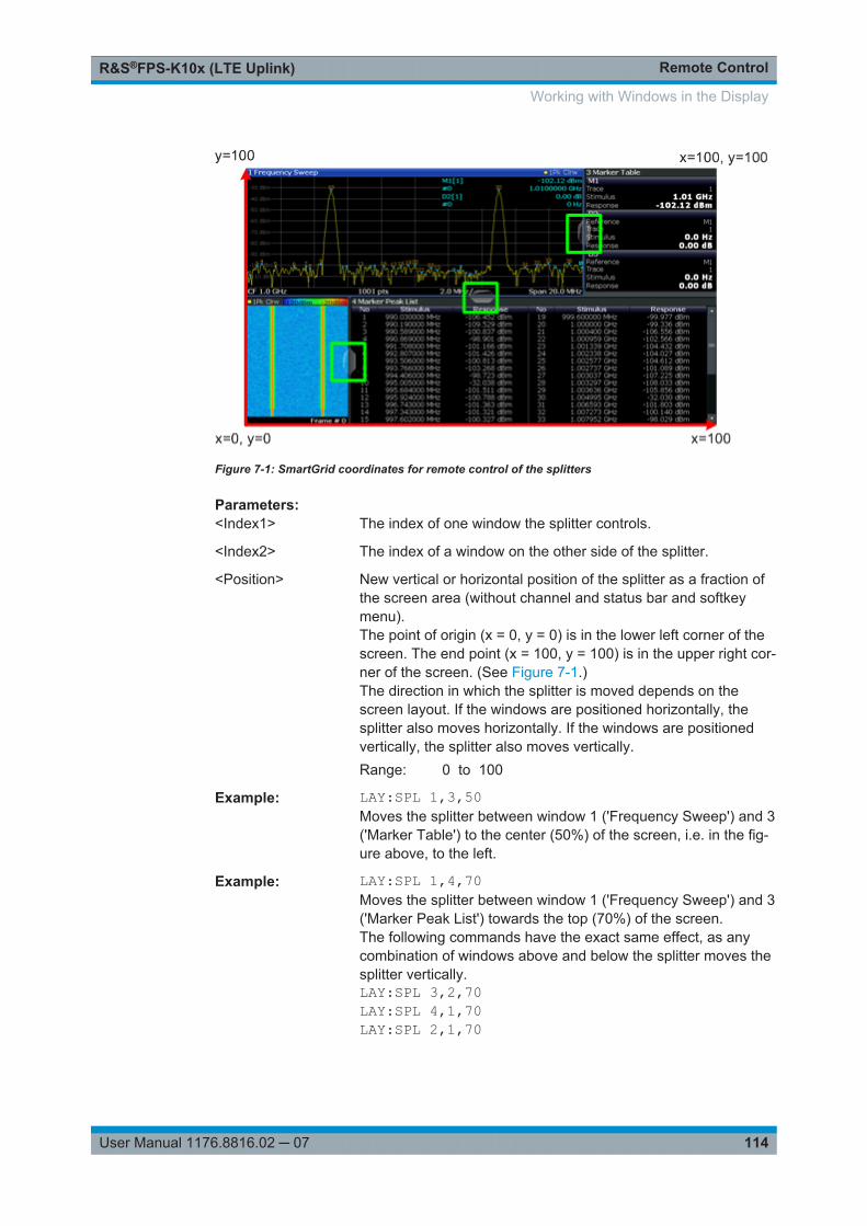
Remote ControlR&S®FPS-K10x (LTE Uplink)
114User Manual 1176.8816.02 ─ 07
Figure 7-1: SmartGrid coordinates for remote control of the splitters
Parameters:<Index1> The index of one window the splitter controls.
<Index2> The index of a window on the other side of the splitter.
<Position> New vertical or horizontal position of the splitter as a fraction ofthe screen area (without channel and status bar and softkeymenu).The point of origin (x = 0, y = 0) is in the lower left corner of thescreen. The end point (x = 100, y = 100) is in the upper right cor-ner of the screen. (See Figure 7-1.)The direction in which the splitter is moved depends on thescreen layout. If the windows are positioned horizontally, thesplitter also moves horizontally. If the windows are positionedvertically, the splitter also moves vertically.Range: 0 to 100
Example: LAY:SPL 1,3,50Moves the splitter between window 1 ('Frequency Sweep') and 3('Marker Table') to the center (50%) of the screen, i.e. in the fig-ure above, to the left.
Example: LAY:SPL 1,4,70Moves the splitter between window 1 ('Frequency Sweep') and 3('Marker Peak List') towards the top (70%) of the screen.The following commands have the exact same effect, as anycombination of windows above and below the splitter moves thesplitter vertically.LAY:SPL 3,2,70LAY:SPL 4,1,70LAY:SPL 2,1,70
Working with Windows in the Display
Remote ControlR&S®FPS-K10x (LTE Uplink)
115User Manual 1176.8816.02 ─ 07
LAYout:WINDow<n>:ADD? <Direction>,<WindowType>
This command adds a measurement window to the display. Note that with this com-mand, the suffix <n> determines the existing window next to which the new window isadded, as opposed to LAYout:ADD[:WINDow]?, for which the existing window isdefined by a parameter.
To replace an existing window, use the LAYout:WINDow<n>:REPLace command.
This command is always used as a query so that you immediately obtain the name ofthe new window as a result.
Suffix: <n>
.Window
Parameters:<Direction> LEFT | RIGHt | ABOVe | BELow
<WindowType> Type of measurement window you want to add.See LAYout:ADD[:WINDow]? on page 109 for a list of availa-ble window types.
Return values: <NewWindowName> When adding a new window, the command returns its name (by
default the same as its number) as a result.
Example: LAY:WIND1:ADD? LEFT,MTABResult:'2'Adds a new window named '2' with a marker table to the left ofwindow 1.
Usage: Query only
LAYout:WINDow<n>:IDENtify?
This command queries the name of a particular display window (indicated by the <n>suffix) in the active channel.
Note: to query the index of a particular window, use the LAYout:IDENtify[:WINDow]? command.
Suffix: <n>
.Window
Return values: <WindowName> String containing the name of a window.
In the default state, the name of the window is its index.
Example: LAY:WIND2:IDEN?Queries the name of the result display in window 2.Response:'2'
Usage: Query only
Working with Windows in the Display
Remote ControlR&S®FPS-K10x (LTE Uplink)
116User Manual 1176.8816.02 ─ 07
LAYout:WINDow<n>:REMove
This command removes the window specified by the suffix <n> from the display in theactive channel.
The result of this command is identical to the LAYout:REMove[:WINDow] command.
Suffix: <n>
.Window
Example: LAY:WIND2:REMRemoves the result display in window 2.
Usage: Event
LAYout:WINDow<n>:REPLace <WindowType>
This command changes the window type of an existing window (specified by the suffix<n>) in the active channel.
The effect of this command is identical to the LAYout:REPLace[:WINDow] com-mand.
To add a new window, use the LAYout:WINDow<n>:ADD? command.
Suffix: <n>
.Window
Setting parameters: <WindowType> Type of measurement window you want to replace another one
with.See LAYout:ADD[:WINDow]? on page 109 for a list of availa-ble window types.
Example: LAY:WIND2:REPL MTABReplaces the result display in window 2 with a marker table.
Usage: Setting only
7.6 Performing Measurements
7.6.1 Measurements
ABORt.......................................................................................................................... 117INITiate<n>:CONTinuous................................................................................................117INITiate<n>[:IMMediate]..................................................................................................118[SENSe:]SYNC[:CC<cc>][:STATe]?.................................................................................118
Performing Measurements
Remote ControlR&S®FPS-K10x (LTE Uplink)
117User Manual 1176.8816.02 ─ 07
ABORt
This command aborts the measurement in the current channel and resets the triggersystem.
To prevent overlapping execution of the subsequent command before the measure-ment has been aborted successfully, use the *OPC? or *WAI command after ABOR andbefore the next command.
For details see the "Remote Basics" chapter in the R&S FPS User Manual.
To abort a sequence of measurements by the Sequencer, use the INITiate<n>:SEQuencer:ABORt command.
Note on blocked remote control programs:
If a sequential command cannot be completed, for example because a triggered sweepnever receives a trigger, the remote control program will never finish and the remotechannel to the R&S FPS is blocked for further commands. In this case, you must inter-rupt processing on the remote channel first in order to abort the measurement.
To do so, send a "Device Clear" command from the control instrument to the R&S FPSon a parallel channel to clear all currently active remote channels. Depending on theused interface and protocol, send the following commands:
● Visa: viClear()Now you can send the ABORt command on the remote channel performing the mea-surement.
Example: ABOR;:INIT:IMMAborts the current measurement and immediately starts a newone.
Example: ABOR;*WAIINIT:IMMAborts the current measurement and starts a new one onceabortion has been completed.
Usage: Event
INITiate<n>:CONTinuous <State>
This command controls the measurement mode for an individual channel.
Note that in single measurement mode, you can synchronize to the end of the mea-surement with *OPC, *OPC? or *WAI. In continuous measurement mode, synchroniza-tion to the end of the measurement is not possible. Thus, it is not recommended thatyou use continuous measurement mode in remote control, as results like trace data ormarkers are only valid after a single measurement end synchronization.
For details on synchronization see the "Remote Basics" chapter in the R&S FPS UserManual.
Performing Measurements
Remote ControlR&S®FPS-K10x (LTE Uplink)
118User Manual 1176.8816.02 ─ 07
If the measurement mode is changed for a channel while the Sequencer is active (seeINITiate<n>:SEQuencer:IMMediate on page 119) the mode is only consideredthe next time the measurement in that channel is activated by the Sequencer.
Suffix: <n>
.irrelevant
Parameters:<State> ON | OFF | 0 | 1
ON | 1Continuous measurementOFF | 0Single measurement*RST: 0
Example: INIT:CONT OFFSwitches the measurement mode to single measurement.INIT:CONT ONSwitches the measurement mode to continuous measurement.
INITiate<n>[:IMMediate]
This command starts a (single) new measurement.
You can synchronize to the end of the measurement with *OPC, *OPC? or *WAI.
For details on synchronization see the "Remote Basics" chapter in the R&S FPS UserManual.
Suffix: <n>
.irrelevant
Usage: Event
[SENSe:]SYNC[:CC<cc>][:STATe]?
This command queries the current synchronization state.
Suffix: <cc>
.Component Carrier
Return values: <State> The string contains the following information:
A zero represents a failure and a one represents a successfulsynchronization.
Example: //Query synchronization stateSYNC:STAT?Would return, e.g. '1' for successful synchronization.
Usage: Query only
Performing Measurements
Remote ControlR&S®FPS-K10x (LTE Uplink)
119User Manual 1176.8816.02 ─ 07
7.6.2 Measurement Sequences
INITiate<n>:SEQuencer:ABORt.......................................................................................119INITiate<n>:SEQuencer:IMMediate..................................................................................119INITiate<n>:SEQuencer:MODE....................................................................................... 119SYSTem:SEQuencer......................................................................................................120
INITiate<n>:SEQuencer:ABORt
This command stops the currently active sequence of measurements. The Sequenceritself is not deactivated, so you can start a new sequence immediately usingINITiate<n>:SEQuencer:IMMediate on page 119.
To deactivate the Sequencer use SYSTem:SEQuencer on page 120.
Suffix: <n>
.irrelevant
Usage: Event
INITiate<n>:SEQuencer:IMMediate
This command starts a new sequence of measurements by the Sequencer.
Its effect is similar to the INITiate<n>[:IMMediate] command used for a singlemeasurement.
Before this command can be executed, the Sequencer must be activated (seeSYSTem:SEQuencer on page 120).
Suffix: <n>
.irrelevant
Example: SYST:SEQ ONActivates the Sequencer.INIT:SEQ:MODE SINGSets single sequence mode so each active measurement will beperformed once.INIT:SEQ:IMMStarts the sequential measurements.
Usage: Event
INITiate<n>:SEQuencer:MODE <Mode>
This command selects the way the R&S FPS application performs measurementssequentially.
Before this command can be executed, the Sequencer must be activated (seeSYSTem:SEQuencer on page 120).
A detailed programming example is provided in the "Operating Modes" chapter in theR&S FPS User Manual.
Performing Measurements
Remote ControlR&S®FPS-K10x (LTE Uplink)
120User Manual 1176.8816.02 ─ 07
Note: In order to synchronize to the end of a sequential measurement using *OPC,*OPC? or *WAI you must use SINGle Sequence mode.
For details on synchronization see the "Remote Basics" chapter in the R&S FPS UserManual.
Suffix: <n>
.irrelevant
Parameters:<Mode> SINGle
Each measurement is performed once (regardless of the chan-nel's sweep mode), considering each channels' sweep count,until all measurements in all active channels have been per-formed.CONTinuousThe measurements in each active channel are performed oneafter the other, repeatedly (regardless of the channel's sweepmode), in the same order, until the Sequencer is stopped.CDEFinedFirst, a single sequence is performed. Then, only those channelsin continuous sweep mode (INIT:CONT ON) are repeated.
*RST: CONTinuous
Example: SYST:SEQ ONActivates the Sequencer.INIT:SEQ:MODE SINGSets single sequence mode so each active measurement will beperformed once.INIT:SEQ:IMMStarts the sequential measurements.
SYSTem:SEQuencer <State>
This command turns the Sequencer on and off. The Sequencer must be active beforeany other Sequencer commands (INIT:SEQ...) are executed, otherwise an error willoccur.
A detailed programming example is provided in the "Operating Modes" chapter in theR&S FPS User Manual.
Parameters:<State> ON | OFF | 0 | 1
ON | 1The Sequencer is activated and a sequential measurement isstarted immediately.OFF | 0The Sequencer is deactivated. Any running sequential measure-ments are stopped. Further Sequencer commands (INIT:SEQ...) are not available.
*RST: 0
Performing Measurements
Remote ControlR&S®FPS-K10x (LTE Uplink)
121User Manual 1176.8816.02 ─ 07
Example: SYST:SEQ ONActivates the Sequencer.INIT:SEQ:MODE SINGSets single Sequencer mode so each active measurement willbe performed once.INIT:SEQ:IMMStarts the sequential measurements.SYST:SEQ OFF
7.7 Remote Commands to Read Trace Data
● Using the TRACe[:DATA] Command....................................................................121● Remote Commands to Read Measurement Results.............................................131
7.7.1 Using the TRACe[:DATA] Command
This chapter contains information on the TRACe:DATA command and a detaileddescription of the characteristics of that command.
The TRACe:DATA command queries the trace data or results of the currently activemeasurement or result display. The type, number and structure of the return values arespecific for each result display. In case of results that have any kind of unit, the com-mand returns the results in the unit you have currently set for that result display.
Note also that return values for results that are available for both downlink and uplinkmay be different.
For several result displays, the command also supports various SCPI parameters incombination with the query. If available, each SCPI parameter returns a differentaspect of the results. If SCPI parameters are supported, you have to quote one in thequery.
Example: TRAC2:DATA? TRACE1
The format of the return values is either in ASCII or binary characters and depends onthe format you have set with FORMat[:DATA].
Following this detailed description, you will find a short summary of the most importantfunctions of the command (TRACe<n>[:DATA]?).
Remote Commands to Read Trace Data

Remote ControlR&S®FPS-K10x (LTE Uplink)
122User Manual 1176.8816.02 ─ 07
Selecting a measurement windowBefore querying results, you have to select the measurement window with the suffix<n> at TRACe. The range of <n> depends on the number of active measurement win-dows.On an R&S FSQ or R&S FSV, the suffix <n> was not supported. On these instruments,you had to select the measurement window with DISPlay:WINDow<n>:SELect first.
For measurements on aggregated carriers or multiple antennas, where each measure-ment window has subwindows, you have to select the subwindow first withDISPlay[:WINDow<n>][:SUBWindow<w>]:SELect.
● Adjacent Channel Leakage Ratio..........................................................................122● Allocation Summary.............................................................................................. 122● Bit Stream............................................................................................................. 123● Capture Buffer.......................................................................................................124● CCDF.................................................................................................................... 124● Channel and Spectrum Flatness...........................................................................124● Channel and Spectrum Flatness Difference......................................................... 125● Channel Flatness SRS..........................................................................................125● Group Delay..........................................................................................................125● Constellation Diagram...........................................................................................126● EVM vs Carrier......................................................................................................126● EVM vs Subframe................................................................................................. 127● EVM vs Symbol.....................................................................................................127● EVM vs Symbol x Carrier......................................................................................127● Frequency Error vs Symbol...................................................................................128● Inband Emission....................................................................................................128● Power Spectrum....................................................................................................128● Power vs Symbol x Carrier....................................................................................129● Spectrum Emission Mask......................................................................................129● Return Value Codes..............................................................................................129
7.7.1.1 Adjacent Channel Leakage Ratio
For the ACLR result display, the number and type of returns values depend on theparameter.
● TRACE1Returns one value for each trace point.
7.7.1.2 Allocation Summary
For the Allocation Summary, the command returns seven values for each line of thetable.
<subframe>, <allocation ID>, <number of RB>, <offset RB>,<modulation>, <absolute power>, <EVM>, ...
Remote Commands to Read Trace Data
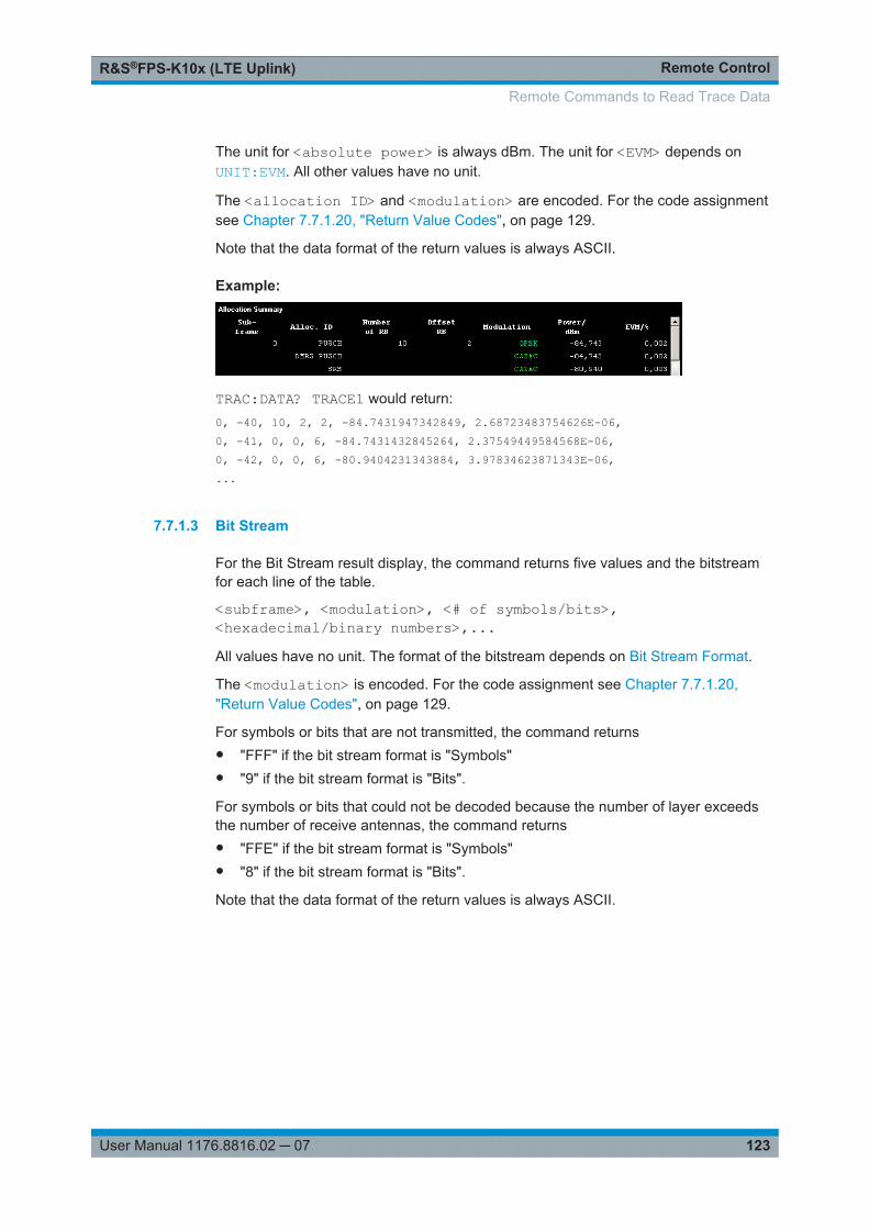
Remote ControlR&S®FPS-K10x (LTE Uplink)
123User Manual 1176.8816.02 ─ 07
The unit for <absolute power> is always dBm. The unit for <EVM> depends onUNIT:EVM. All other values have no unit.
The <allocation ID> and <modulation> are encoded. For the code assignmentsee Chapter 7.7.1.20, "Return Value Codes", on page 129.
Note that the data format of the return values is always ASCII.
Example:
TRAC:DATA? TRACE1 would return:0, -40, 10, 2, 2, -84.7431947342849, 2.68723483754626E-06,0, -41, 0, 0, 6, -84.7431432845264, 2.37549449584568E-06,0, -42, 0, 0, 6, -80.9404231343884, 3.97834623871343E-06,...
7.7.1.3 Bit Stream
For the Bit Stream result display, the command returns five values and the bitstreamfor each line of the table.
<subframe>, <modulation>, <# of symbols/bits>,<hexadecimal/binary numbers>,...All values have no unit. The format of the bitstream depends on Bit Stream Format.
The <modulation> is encoded. For the code assignment see Chapter 7.7.1.20,"Return Value Codes", on page 129.
For symbols or bits that are not transmitted, the command returns● "FFF" if the bit stream format is "Symbols"● "9" if the bit stream format is "Bits".
For symbols or bits that could not be decoded because the number of layer exceedsthe number of receive antennas, the command returns● "FFE" if the bit stream format is "Symbols"● "8" if the bit stream format is "Bits".
Note that the data format of the return values is always ASCII.
Remote Commands to Read Trace Data
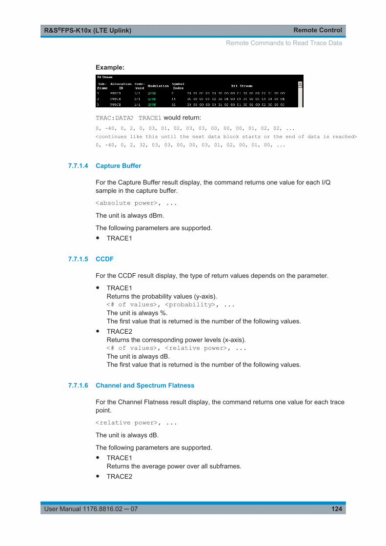
Remote ControlR&S®FPS-K10x (LTE Uplink)
124User Manual 1176.8816.02 ─ 07
Example:
TRAC:DATA? TRACE1 would return:0, -40, 0, 2, 0, 03, 01, 02, 03, 03, 00, 00, 00, 01, 02, 02, ...<continues like this until the next data block starts or the end of data is reached>0, -40, 0, 2, 32, 03, 03, 00, 00, 03, 01, 02, 00, 01, 00, ...
7.7.1.4 Capture Buffer
For the Capture Buffer result display, the command returns one value for each I/Qsample in the capture buffer.
<absolute power>, ...The unit is always dBm.
The following parameters are supported.● TRACE1
7.7.1.5 CCDF
For the CCDF result display, the type of return values depends on the parameter.
● TRACE1Returns the probability values (y-axis).<# of values>, <probability>, ...The unit is always %.The first value that is returned is the number of the following values.
● TRACE2Returns the corresponding power levels (x-axis).<# of values>, <relative power>, ...The unit is always dB.The first value that is returned is the number of the following values.
7.7.1.6 Channel and Spectrum Flatness
For the Channel Flatness result display, the command returns one value for each tracepoint.
<relative power>, ...The unit is always dB.
The following parameters are supported.● TRACE1
Returns the average power over all subframes.● TRACE2
Remote Commands to Read Trace Data
Remote ControlR&S®FPS-K10x (LTE Uplink)
125User Manual 1176.8816.02 ─ 07
Returns the minimum power found over all subframes. If you are analyzing a partic-ular subframe, it returns nothing.
● TRACE3Returns the maximum power found over all subframes. If you are analyzing a par-ticular subframe, it returns nothing.
7.7.1.7 Channel and Spectrum Flatness Difference
For the Channel Flatness Difference result display, the command returns one value foreach trace point.
<relative power>, ...The unit is always dB. The number of values depends on the selected LTE bandwidth.
The following parameters are supported.● TRACE1
Returns the average power over all subframes.● TRACE2
Returns the minimum power found over all subframes. If you are analyzing a partic-ular subframe, it returns nothing.
● TRACE3Returns the maximum power found over all subframes. If you are analyzing a par-ticular subframe, it returns nothing.
7.7.1.8 Channel Flatness SRS
For the Channel Flatness SRS result display, the command returns one value for eachtrace point.
<relative power>, ...The unit is always dB.
The following parameters are supported.● TRACE1
Returns the average power over all subframes.● TRACE2
Returns the minimum power found over all subframes. If you are analyzing a partic-ular subframe, it returns nothing.
● TRACE3Returns the maximum power found over all subframes. If you are analyzing a par-ticular subframe, it returns nothing.
7.7.1.9 Group Delay
For the Group Delay result display, the command returns one value for each tracepoint.
<group delay>, ...
Remote Commands to Read Trace Data
Remote ControlR&S®FPS-K10x (LTE Uplink)
126User Manual 1176.8816.02 ─ 07
The unit is always ns. The number of values depends on the selected LTE bandwidth.
The following parameters are supported.● TRACE1
Returns the average group delay over all subframes.● TRACE2
Returns the minimum group delay found over all subframes. If you are analyzing aparticular subframe, it returns nothing.
● TRACE3Returns the maximum group delay found over all subframes. If you are analyzing aparticular subframe, it returns nothing.
7.7.1.10 Constellation Diagram
For the Constellation Diagram, the command returns two values for each constellationpoint.
<I[SF0][Sym0][Carrier1]>, <Q[SF0][Sym0][Carrier1]>, ..., <I[SF0][Sym0][Carrier(n)]>, <Q[SF0][Sym0][Car-rier(n)]>,
<I[SF0][Sym1][Carrier1]>, <Q[SF0][Sym1][Carrier1]>, ..., <I[SF0][Sym1][Carrier(n)]>, <Q[SF0][Sym1][Car-rier(n)]>,
<I[SF0][Sym(n)][Carrier1]>, <Q[SF0][Sym(n)][Carrier1]>, ..., <I[SF0][Sym(n)][Carrier(n)]>, <Q[SF0][Sym(n)][Carrier(n)]>,
<I[SF1][Sym0][Carrier1]>, <Q[SF1][Sym0][Carrier1]>, ..., <I[SF1][Sym0][Carrier(n)]>, <Q[SF1][Sym0][Car-rier(n)]>,
<I[SF1][Sym1][Carrier1]>, <Q[SF1][Sym1][Carrier1]>, ..., <I[SF1][Sym1][Carrier(n)]>, <Q[SF1][Sym1][Car-rier(n)]>,
<I[SF(n)][Sym(n)][Carrier1]>, <Q[SF(n)][Sym(n)][Carrier1]>, ..., <I[SF(n)][Sym(n)][Carrier(n)]>, <Q[SF(n)][Sym(n)][Carrier(n)]>
With SF = subframe and Sym = symbol of that subframe.
The I and Q values have no unit.
The number of return values depends on the constellation selection. By default, itreturns all resource elements including the DC carrier.
The following parameters are supported.● TRACE1
Returns all constellation points included in the selection.● TRACE2
Returns the constellation points of the reference symbols included in the selection.● TRACE3
Returns the constellation points of the SRS included in the selection.
7.7.1.11 EVM vs Carrier
For the EVM vs Carrier result display, the command returns one value for each subcar-rier that has been analyzed.
<EVM>, ...
Remote Commands to Read Trace Data

Remote ControlR&S®FPS-K10x (LTE Uplink)
127User Manual 1176.8816.02 ─ 07
The unit depends on UNIT:EVM.
The following parameters are supported.● TRACE1
Returns the average EVM over all subframes● TRACE2
Returns the minimum EVM found over all subframes. If you are analyzing a particu-lar subframe, it returns nothing.
● TRACE3Returns the maximum EVM found over all subframes. If you are analyzing a partic-ular subframe, it returns nothing.
7.7.1.12 EVM vs Subframe
For the EVM vs Subframe result display, the command returns one value for each sub-frame that has been analyzed.
<EVM>, ...The unit depends on UNIT:EVM.
The following parameters are supported.● TRACE1
7.7.1.13 EVM vs Symbol
For the EVM vs Symbol result display, the command returns one value for each OFDMsymbol that has been analyzed.
<EVM>, ...For measurements on a single subframe, the command returns the symbols of thatsubframe only.
The unit depends on UNIT:EVM.
The following parameters are supported.● TRACE1
7.7.1.14 EVM vs Symbol x Carrier
For the EVM vs Symbol x Carrier, the command returns one value for each resourceelement.
<EVM[Symbol(0),Carrier(1)]>, ..., <EVM[Symbol(0),Carrier(n)]>,<EVM[Symbol(1),Carrier(1)]>, ..., <EVM[Symbol(1),Carrier(n)]>,...<EVM[Symbol(n),Carrier(1)]>, ..., <EVM[Symbol(n),Carrier(n)]>,The unit depends on UNIT:EVM.
Remote Commands to Read Trace Data
Remote ControlR&S®FPS-K10x (LTE Uplink)
128User Manual 1176.8816.02 ─ 07
Resource elements that are unused return NAN.
The following parameters are supported.● TRACE1
7.7.1.15 Frequency Error vs Symbol
For the Frequency Error vs Symbol result display, the command returns one value foreach OFDM symbol that has been analyzed.
<frequency error>,...The unit is always Hz.
The following parameters are supported.● TRACE1
7.7.1.16 Inband Emission
For the Inband Emission result display, the number and type of returns values dependon the parameter.
● TRACE1Returns the relative resource block indices (x-axis values).<RB index>, ...The resource block index has no unit.
● TRACE2Returns one value for each resource block index.<relative power>, ...The unit of the relative inband emission is dB.
● TRACE3Returns the data points of the upper limit line.<limit>, ...The unit is always dB.
Note that you have to select a particular subframe to get results.
7.7.1.17 Power Spectrum
For the Power Spectrum result display, the command returns one value for each tracepoint.
<power>,...The unit is always dBm/Hz.
The following parameters are supported.● TRACE1
Remote Commands to Read Trace Data
Remote ControlR&S®FPS-K10x (LTE Uplink)
129User Manual 1176.8816.02 ─ 07
7.7.1.18 Power vs Symbol x Carrier
For the Power vs Symbol x Carrier, the command returns one value for each resourceelement.
<P[Symbol(0),Carrier(1)]>, ..., <P[Symbol(0),Carrier(n)]>,<P[Symbol(1),Carrier(1)]>, ..., <P[Symbol(1),Carrier(n)]>,...<P[Symbol(n),Carrier(1)]>, ..., <P[Symbol(n),Carrier(n)]>,with P = Power of a resource element.
The unit is always dBm.
Resource elements that are unused return NAN.
The following parameters are supported.● TRACE1
7.7.1.19 Spectrum Emission Mask
For the SEM measurement, the number and type of returns values depend on theparameter.
● TRACE1Returns one value for each trace point.<absolute power>, ...The unit is always dBm.
● LISTReturns the contents of the SEM table. For every frequency in the spectrum emis-sion mask, it returns 11 values.<index>, <start frequency in Hz>, <stop frequency in Hz>,<RBW in Hz>, <limit fail frequency in Hz>, <absolute power indBm>, <relative power in dBc>, <limit distance in dB>, <limitcheck result>, <reserved>, <reserved>...The <limit check result> is either a 0 (for PASS) or a 1 (for FAIL).
7.7.1.20 Return Value Codes
<number of symbols or bits>
In hexadecimal mode, this represents the number of symbols to be transmitted. Inbinary mode, it represents the number of bits to be transmitted.
<allocation ID>
Represents the allocation ID. The value is a number in the range {1...-70}.● 1 = Reference symbol● 0 = Data symbol
Remote Commands to Read Trace Data
Remote ControlR&S®FPS-K10x (LTE Uplink)
130User Manual 1176.8816.02 ─ 07
● -1 = Invalid● -40 = PUSCH● -41 = DMRS PUSCH● -42 = SRS PUSCH● -50 = PUCCH● -51 = DMRS PUCCH● -70 = PRACH
<channel type>
● 0 = TX channel● 1 = adjacent channel● 2 = alternate channel
<codeword>
Represents the codeword of an allocation. The range is {0...6}.● 0 = 1/1● 1 = 1/2● 2 = 2/2● 3 = 1/4● 4 = 2/4● 5 = 3/4● 6 = 4/4
<modulation>
Represents the modulation scheme.● 0 = unrecognized● 1 = RBPSK● 2 = QPSK● 3 = 16QAM● 4 = 64QAM● 5 = 8PSK● 6 = CAZAC● 7 = mixed modulation● 8 = BPSK● 14 = 256QAM
FORMat[:DATA].............................................................................................................131TRACe<n>[:DATA]?.......................................................................................................131
Remote Commands to Read Trace Data
Remote ControlR&S®FPS-K10x (LTE Uplink)
131User Manual 1176.8816.02 ─ 07
FORMat[:DATA] <Format>
This command specifies the data format for the data transmission between the LTEmeasurement application and the remote client. Supported formats are ASCII orREAL32.
Note that the following result displays do not support the REAL32 format. The returnvalues for those are always in ASCII format.● Allocation summary● Bitstream
Parameters:<Format> ASCii | REAL
*RST: ASCii
Example: FORM REALThe software will send binary data in Real32 data format.
TRACe<n>[:DATA]? <Result>
This command returns the trace data for the current measurement or result display.
For more information, see Chapter 7.7.1, "Using the TRACe[:DATA] Command",on page 121.
Suffix: <n>
.Window
Query parameters: <TraceNumber> TRACE1 | TRACE2 | TRACE3
LIST
Example: TRAC2? TRACE1Queries results of the second measurement window. The type ofdata that is returned by the parameter (TRACE1) depends on theresult display shown in measurement window 2.
Usage: Query only
7.7.2 Remote Commands to Read Measurement Results
CALCulate<n>:MARKer<m>:FUNCtion:POWer:RESult[:CURRent]?................................... 131FORMat[:DATA].............................................................................................................133
CALCulate<n>:MARKer<m>:FUNCtion:POWer:RESult[:CURRent]? <ResultType>
This command queries the current results of the ACLR measurement or the total signalpower level of the SEM measurement.
To get a valid result, you have to perform a complete measurement with synchroniza-tion to the end of the measurement before reading out the result. This is only possiblefor single sweeps.
Remote Commands to Read Trace Data
Remote ControlR&S®FPS-K10x (LTE Uplink)
132User Manual 1176.8816.02 ─ 07
Suffix: <m>
.Marker
<n> Window
Query parameters: <ResultType> CPOW
This parameter queries the channel power of the referencerange.MCACQueries the channel powers of the ACLR, MC ACLR and Cumu-lative ACLR measurements as shown in the ACLR table.Where available, this parameter also queries the power of theadjacent channels (for example in the ACLR measurement).GACLrQueries the ACLR values for each gap channel in the MC ACLRmeasurement.
Return values: <Result> Results for the Spectrum Emission Mask measurement:
Power level in dBm.Results for the ACLR measurements:Relative power levels of the ACLR channels. The number ofreturn values depends on the number of transmission and adja-cent channels. The order of return values is:• <TXChannelPower> is the power of the transmission channelin dBm• <LowerAdjChannelPower> is the relative power of the loweradjacent channel in dB• <UpperAdjChannelPower> is the relative power of the upperadjacent channel in dB• <1stLowerAltChannelPower> is the relative power of the firstlower alternate channel in dB• <1stUpperAltChannelPower> is the relative power of the firstlower alternate channel in dB(...)• <nthLowerAltChannelPower> is the relative power of a subse-quent lower alternate channel in dB• <nthUpperAltChannelPower> is the relative power of a subse-quent lower alternate channel in dB
Example: CALC1:MARK:FUNC:POW:RES? MCACReturns the current ACLR measurement results.
Usage: Query only
Manual operation: See "ACLR" on page 31See "Multi Carrier ACLR" on page 34
Remote Commands to Read Trace Data
Remote ControlR&S®FPS-K10x (LTE Uplink)
133User Manual 1176.8816.02 ─ 07
FORMat[:DATA] <Format>
This command specifies the data format for the data transmission between the LTEmeasurement application and the remote client. Supported formats are ASCII orREAL32.
Note that the following result displays do not support the REAL32 format. The returnvalues for those are always in ASCII format.● Allocation summary● Bitstream
Parameters:<Format> ASCii | REAL
*RST: ASCii
Example: FORM REALThe software will send binary data in Real32 data format.
7.8 Remote Commands to Read Numeric Results
● Frame Results.......................................................................................................133● Result for Selection...............................................................................................137● Time Alignment Error............................................................................................ 142● Marker Table.........................................................................................................143● CCDF Table.......................................................................................................... 146
7.8.1 Frame Results
FETCh[:CC<cc>]:SUMMary:EVM:SDQP[:AVERage]?........................................................133FETCh[:CC<cc>]:SUMMary:EVM:SDSF[:AVERage]?........................................................ 134FETCh[:CC<cc>]:SUMMary:EVM:SDST[:AVERage]?........................................................ 134FETCh[:CC<cc>]:SUMMary:EVM:SDTS[:AVERage]?........................................................ 134FETCh[:CC<cc>]:SUMMary:EVM:UCCD[:AVERage]?....................................................... 135FETCh[:CC<cc>]:SUMMary:EVM:UCCH[:AVERage]?....................................................... 135FETCh[:CC<cc>]:SUMMary:EVM:UPRA[:AVERage]?........................................................135FETCh[:CC<cc>]:SUMMary:EVM:USQP[:AVERage]?........................................................136FETCh[:CC<cc>]:SUMMary:EVM:USSF[:AVERage]?........................................................ 136FETCh[:CC<cc>]:SUMMary:EVM:USST[:AVERage]?........................................................ 136FETCh[:CC<cc>]:SUMMary:EVM:USTS[:AVERage]?........................................................ 137
FETCh[:CC<cc>]:SUMMary:EVM:SDQP[:AVERage]?
This command queries the EVM of all DMRS PUSCH resource elements with QPSKmodulation.
Suffix: <cc>
.Component Carrier
Remote Commands to Read Numeric Results
Remote ControlR&S®FPS-K10x (LTE Uplink)
134User Manual 1176.8816.02 ─ 07
Return values: <EVM> <numeric value>
EVM in % or dB, depending on the unit you have set.
Example: //Query EVMFETC:SUMM:EVM:SDQP?
Usage: Query only
Manual operation: See "Result Summary" on page 24
FETCh[:CC<cc>]:SUMMary:EVM:SDSF[:AVERage]?
This command queries the EVM of all DMRS PUSCH resource elements with 64QAMmodulation.
Suffix: <cc>
.Component Carrier
Return values: <EVM> <numeric value>
EVM in % or dB, depending on the unit you have set.
Example: //Query EVMFETC:SUMM:EVM:SDSF?
Usage: Query only
Manual operation: See "Result Summary" on page 24
FETCh[:CC<cc>]:SUMMary:EVM:SDST[:AVERage]?
This command queries the EVM of all DMRS PUSCH resource elements with 16QAMmodulation.
Suffix: <cc>
.Component Carrier
Return values: <EVM> <numeric value>
EVM in % or dB, depending on the unit you have set.
Example: //Query EVMFETC:SUMM:EVM:SDST?
Usage: Query only
Manual operation: See "Result Summary" on page 24
FETCh[:CC<cc>]:SUMMary:EVM:SDTS[:AVERage]?
This command queries the EVM of all DMRS PUSCH resource elements with 256QAMmodulation.
Remote Commands to Read Numeric Results
Remote ControlR&S®FPS-K10x (LTE Uplink)
135User Manual 1176.8816.02 ─ 07
Suffix: <cc>
.Component Carrier
Return values: <EVM> <numeric value>
EVM in % or dB, depending on the unit you have set.
Example: //Query EVMFETC:SUMM:EVM:DSTS?
Usage: Query only
Manual operation: See "Result Summary" on page 24
FETCh[:CC<cc>]:SUMMary:EVM:UCCD[:AVERage]?
This command queries the EVM of all DMRS PUCCH resource elements.
Suffix: <cc>
.Component Carrier
Return values: <EVM> EVM in % or dB, depending on the unit you have set.
Example: //Query EVMFETC:SUMM:EVM:UCCD?
Usage: Query only
Manual operation: See "Result Summary" on page 24
FETCh[:CC<cc>]:SUMMary:EVM:UCCH[:AVERage]?
This command queries the EVM of all PUCCH resource elements.
Suffix: <cc>
.Component Carrier
Return values: <EVM> EVM in % or dB, depending on the unit you have set.
Example: //Query EVMFETC:SUMM:EVM:UCCH?
Usage: Query only
Manual operation: See "Result Summary" on page 24
FETCh[:CC<cc>]:SUMMary:EVM:UPRA[:AVERage]?
This command queries the EVM of all PRACH resource elements.
Suffix: <cc>
.Component Carrier
Remote Commands to Read Numeric Results
Remote ControlR&S®FPS-K10x (LTE Uplink)
136User Manual 1176.8816.02 ─ 07
Return values: <EVM> EVM in % or dB, depending on the unit you have set.
Example: //Query EVMFETC:SUMM:EVM:UPRA?
Usage: Query only
Manual operation: See "Result Summary" on page 24
FETCh[:CC<cc>]:SUMMary:EVM:USQP[:AVERage]?
This command queries the EVM of all PUSCH resource elements with QPSK modula-tion.
Suffix: <cc>
.Component Carrier
Return values: <EVM> <numeric value>
EVM in % or dB, depending on the unit you have set.
Example: //Query EVMFETC:SUMM:EVM:USQP?
Usage: Query only
Manual operation: See "Result Summary" on page 24
FETCh[:CC<cc>]:SUMMary:EVM:USSF[:AVERage]?
This command queries the EVM of all PUSCH resource elements with 64QAM modula-tion.
Suffix: <cc>
.Component Carrier
Return values: <EVM> <numeric value>
EVM in % or dB, depending on the unit you have set.
Example: //Query EVMFETC:SUMM:EVM:USSF?
Usage: Query only
Manual operation: See "Result Summary" on page 24
FETCh[:CC<cc>]:SUMMary:EVM:USST[:AVERage]?
This command queries the EVM of all PUSCH resource elements with 16QAM modula-tion.
Suffix: <cc>
.Component Carrier
Remote Commands to Read Numeric Results
Remote ControlR&S®FPS-K10x (LTE Uplink)
137User Manual 1176.8816.02 ─ 07
Return values: <EVM> EVM in % or dB, depending on the unit you have set.
Example: //Query EVMFETC:SUMM:EVM:USST?
Usage: Query only
Manual operation: See "Result Summary" on page 24
FETCh[:CC<cc>]:SUMMary:EVM:USTS[:AVERage]?
This command queries the EVM of all PUSCH resource elements with 256QAM modu-lation.
Suffix: <cc>
.Component Carrier
Return values: <EVM> <numeric value>
EVM in % or dB, depending on the unit you have set.
Example: //Query EVMFETC:SUMM:EVM:USTS?
Usage: Query only
Manual operation: See "Result Summary" on page 24
7.8.2 Result for Selection
FETCh[:CC<cc>]:SUMMary:CRESt[:AVERage]?...............................................................138FETCh[:CC<cc>]:SUMMary:EVM[:ALL]:MAXimum?.......................................................... 138FETCh[:CC<cc>]:SUMMary:EVM[:ALL]:MINimum?........................................................... 138FETCh[:CC<cc>]:SUMMary:EVM[:ALL][:AVERage]?......................................................... 138FETCh[:CC<cc>]:SUMMary:EVM:PCHannel:MAXimum?................................................... 138FETCh[:CC<cc>]:SUMMary:EVM:PCHannel:MINimum?.................................................... 138FETCh[:CC<cc>]:SUMMary:EVM:PCHannel[:AVERage]?.................................................. 138FETCh[:CC<cc>]:SUMMary:EVM:PSIGnal:MAXimum?......................................................139FETCh[:CC<cc>]:SUMMary:EVM:PSIGnal:MINimum?.......................................................139FETCh[:CC<cc>]:SUMMary:EVM:PSIGnal[:AVERage]?.....................................................139FETCh[:CC<cc>]:SUMMary:FERRor:MAXimum?.............................................................. 139FETCh[:CC<cc>]:SUMMary:FERRor:MINimum?............................................................... 139FETCh[:CC<cc>]:SUMMary:FERRor[:AVERage]?.............................................................139FETCh[:CC<cc>]:SUMMary:GIMBalance:MAXimum?........................................................140FETCh[:CC<cc>]:SUMMary:GIMBalance:MINimum?......................................................... 140FETCh[:CC<cc>]:SUMMary:GIMBalance[:AVERage]?.......................................................140FETCh[:CC<cc>]:SUMMary:IQOFfset:MAXimum?.............................................................140FETCh[:CC<cc>]:SUMMary:IQOFfset:MINimum?..............................................................140FETCh[:CC<cc>]:SUMMary:IQOFfset[:AVERage]?............................................................140FETCh[:CC<cc>]:SUMMary:POWer:MAXimum?............................................................... 140FETCh[:CC<cc>]:SUMMary:POWer:MINimum?................................................................ 140
Remote Commands to Read Numeric Results
Remote ControlR&S®FPS-K10x (LTE Uplink)
138User Manual 1176.8816.02 ─ 07
FETCh[:CC<cc>]:SUMMary:POWer[:AVERage]?.............................................................. 140FETCh[:CC<cc>]:SUMMary:QUADerror:MAXimum?..........................................................141FETCh[:CC<cc>]:SUMMary:QUADerror:MINimum?...........................................................141FETCh[:CC<cc>]:SUMMary:QUADerror[:AVERage]?........................................................ 141FETCh[:CC<cc>]:SUMMary:SERRor:MAXimum?..............................................................141FETCh[:CC<cc>]:SUMMary:SERRor:MINimum?...............................................................141FETCh[:CC<cc>]:SUMMary:SERRor[:AVERage]?.............................................................141FETCh[:CC<cc>]:SUMMary:TFRame?.............................................................................142
FETCh[:CC<cc>]:SUMMary:CRESt[:AVERage]?
This command queries the average crest factor as shown in the result summary.
Suffix: <cc>
.Component Carrier
Return values: <CrestFactor> <numeric value>
Crest Factor in dB.
Example: //Query crest factorFETC:SUMM:CRES?
Usage: Query only
Manual operation: See "Result Summary" on page 24
FETCh[:CC<cc>]:SUMMary:EVM[:ALL]:MAXimum?FETCh[:CC<cc>]:SUMMary:EVM[:ALL]:MINimum?FETCh[:CC<cc>]:SUMMary:EVM[:ALL][:AVERage]?This command queries the EVM of all resource elements.
Suffix: <cc>
.Component Carrier
Return values: <EVM> <numeric value>
Minimum, maximum or average EVM, depending on the lastcommand syntax element.The unit is % or dB, depending on your selection.
Example: //Query EVMFETC:SUMM:EVM?
Usage: Query only
Manual operation: See "Result Summary" on page 24
FETCh[:CC<cc>]:SUMMary:EVM:PCHannel:MAXimum?FETCh[:CC<cc>]:SUMMary:EVM:PCHannel:MINimum?FETCh[:CC<cc>]:SUMMary:EVM:PCHannel[:AVERage]?This command queries the EVM of all physical channel resource elements.
Remote Commands to Read Numeric Results
Remote ControlR&S®FPS-K10x (LTE Uplink)
139User Manual 1176.8816.02 ─ 07
Suffix: <cc>
.Component Carrier
Return values: <EVM> <numeric value>
EVM in % or dB, depending on the unit you have set.
Example: //Query EVMFETC:SUMM:EVM:PCH?
Usage: Query only
Manual operation: See "Result Summary" on page 24
FETCh[:CC<cc>]:SUMMary:EVM:PSIGnal:MAXimum?FETCh[:CC<cc>]:SUMMary:EVM:PSIGnal:MINimum?FETCh[:CC<cc>]:SUMMary:EVM:PSIGnal[:AVERage]?This command queries the EVM of all physical signal resource elements.
Suffix: <cc>
.Component Carrier
Return values: <EVM> <numeric value>
Minimum, maximum or average EVM, depending on the lastcommand syntax element.The unit is % or dB, depending on your selection.
Example: //Query EVMFETC:SUMM:EVM:PSIG?
Usage: Query only
Manual operation: See "Result Summary" on page 24
FETCh[:CC<cc>]:SUMMary:FERRor:MAXimum?FETCh[:CC<cc>]:SUMMary:FERRor:MINimum?FETCh[:CC<cc>]:SUMMary:FERRor[:AVERage]?This command queries the frequency error.
Suffix: <cc>
.Component Carrier
Return values: <FreqError> <numeric value>
Minimum, maximum or average frequency error, depending onthe last command syntax element.Default unit: Hz
Example: //Query average frequency errorFETC:SUMM:FERR?
Usage: Query only
Remote Commands to Read Numeric Results
Remote ControlR&S®FPS-K10x (LTE Uplink)
140User Manual 1176.8816.02 ─ 07
Manual operation: See "Result Summary" on page 24
FETCh[:CC<cc>]:SUMMary:GIMBalance:MAXimum?FETCh[:CC<cc>]:SUMMary:GIMBalance:MINimum?FETCh[:CC<cc>]:SUMMary:GIMBalance[:AVERage]?This command queries the I/Q gain imbalance.
Suffix: <cc>
.Component Carrier
Return values: <GainImbalance> <numeric value>
Minimum, maximum or average I/Q imbalance, depending onthe last command syntax element.Default unit: dB
Example: //Query average gain imbalanceFETC:SUMM:GIMB?
Usage: Query only
Manual operation: See "Result Summary" on page 24
FETCh[:CC<cc>]:SUMMary:IQOFfset:MAXimum?FETCh[:CC<cc>]:SUMMary:IQOFfset:MINimum?FETCh[:CC<cc>]:SUMMary:IQOFfset[:AVERage]?This command queries the I/Q offset.
Suffix: <cc>
.Component Carrier
Return values: <IQOffset> <numeric value>
Minimum, maximum or average I/Q offset, depending on the lastcommand syntax element.Default unit: dB
Example: //Query average IQ offsetFETC:SUMM:IQOF?
Usage: Query only
Manual operation: See "Result Summary" on page 24
FETCh[:CC<cc>]:SUMMary:POWer:MAXimum?FETCh[:CC<cc>]:SUMMary:POWer:MINimum?FETCh[:CC<cc>]:SUMMary:POWer[:AVERage]?This command queries the total power.
Suffix: <cc>
.Component Carrier
Remote Commands to Read Numeric Results
Remote ControlR&S®FPS-K10x (LTE Uplink)
141User Manual 1176.8816.02 ─ 07
Return values: <Power> <numeric value>
Minimum, maximum or average power, depending on the lastcommand syntax element.Default unit: dBm
Example: //Query average total powerFETC:SUMM:POW?
Usage: Query only
Manual operation: See "Result Summary" on page 24
FETCh[:CC<cc>]:SUMMary:QUADerror:MAXimum?FETCh[:CC<cc>]:SUMMary:QUADerror:MINimum?FETCh[:CC<cc>]:SUMMary:QUADerror[:AVERage]?This command queries the quadrature error.
Suffix: <cc>
.Component Carrier
Return values: <QuadError> <numeric value>
Minimum, maximum or average quadrature error, depending onthe last command syntax element.Default unit: deg
Example: //Query average quadrature errorFETC:SUMM:QUAD?
Usage: Query only
Manual operation: See "Result Summary" on page 24
FETCh[:CC<cc>]:SUMMary:SERRor:MAXimum?FETCh[:CC<cc>]:SUMMary:SERRor:MINimum?FETCh[:CC<cc>]:SUMMary:SERRor[:AVERage]?This command queries the sampling error.
Suffix: <cc>
.Component Carrier
Return values: <SamplingError> <numeric value>
Minimum, maximum or average sampling error, depending onthe last command syntax element.Default unit: ppm
Example: //Query average sampling errorFETC:SUMM:SERR?
Usage: Query only
Remote Commands to Read Numeric Results
Remote ControlR&S®FPS-K10x (LTE Uplink)
142User Manual 1176.8816.02 ─ 07
Manual operation: See "Result Summary" on page 24
FETCh[:CC<cc>]:SUMMary:TFRame?
This command queries the (sub)frame start offset as shown in the capture buffer.
Note that you have to select a particular subframe; otherwise the command returns anerror.
Suffix: <cc>
.Component Carrier
Return values: <Offset> Time difference between the (sub)frame start and capture buffer
start.Default unit: s
Example: //Query subframe start offsetFETC:SUMM:TFR?
Usage: Query only
Manual operation: See "Capture Buffer" on page 16
7.8.3 Time Alignment Error
FETCh:FEPPm[:CC<cc>]:MAXimum?..............................................................................142FETCh:FEPPm[:CC<cc>]:MINimum?...............................................................................142FETCh:FEPPm[:CC<cc>][:AVERage]?.............................................................................142FETCh:FERRor[:CC<cc>]:MAXimum?............................................................................. 143FETCh:FERRor[:CC<cc>]:MINimum?.............................................................................. 143FETCh:FERRor[:CC<cc>][:AVERage]?............................................................................ 143FETCh:TAERror[:CC<cc>]:ANTenna<antenna>:MAXimum................................................ 143FETCh:TAERror[:CC<cc>]:ANTenna<antenna>:MINimum................................................. 143FETCh:TAERror[:CC<cc>]:ANTenna<ant>[:AVERage]?.................................................... 143
FETCh:FEPPm[:CC<cc>]:MAXimum?FETCh:FEPPm[:CC<cc>]:MINimum?FETCh:FEPPm[:CC<cc>][:AVERage]?This command queries the Carrier Frequency Error.
Suffix: <cc>
.Component Carrier
Return values: <FrequencyError> Average, minimum or maximum frequency error, depending on
the command syntax.Default unit: ppm
Example: FETC:FERR:MAX?Queries the maximum frequency error.
Remote Commands to Read Numeric Results
Remote ControlR&S®FPS-K10x (LTE Uplink)
143User Manual 1176.8816.02 ─ 07
Usage: Query only
Manual operation: See "Carrier Frequency Error" on page 29
FETCh:FERRor[:CC<cc>]:MAXimum?FETCh:FERRor[:CC<cc>]:MINimum?FETCh:FERRor[:CC<cc>][:AVERage]?This command queries the Carrier Frequency Error.
Suffix: <cc>
.Component Carrier
Return values: <FrequencyError> Average, minimum or maximum frequency error, depending on
the command syntax.Default unit: Hz
Example: FETC:FERR?Queries the average frequency error.
Usage: Query only
Manual operation: See "Carrier Frequency Error" on page 29
FETCh:TAERror[:CC<cc>]:ANTenna<antenna>:MAXimumFETCh:TAERror[:CC<cc>]:ANTenna<antenna>:MINimumFETCh:TAERror[:CC<cc>]:ANTenna<ant>[:AVERage]?This command queries the time alignment error.
Suffix: <cc>
.Component Carrier
Return values: <Time AlignmentError>
Minimum, maximum or average time alignment error, dependingon the last command syntax element.Default unit: s
Example: FETC:TAER:ANT2?Returns the average time alignment error between the referenceantenna and antenna 2 in s.
Usage: Query only
Manual operation: See "Time Alignment Error" on page 29
7.8.4 Marker Table
CALCulate<n>:DELTamarker<m>:X................................................................................ 144CALCulate<n>:DELTamarker<m>:Y?...............................................................................144CALCulate<n>:MARKer<m>:X........................................................................................ 144CALCulate<n>:MARKer<m>:Y?.......................................................................................145
Remote Commands to Read Numeric Results
Remote ControlR&S®FPS-K10x (LTE Uplink)
144User Manual 1176.8816.02 ─ 07
CALCulate<n>:DELTamarker<m>:X <Position>
This command moves a delta marker to a particular coordinate on the x-axis.
If necessary, the command activates the delta marker and positions a referencemarker to the peak power.
Suffix: <m>
.Marker
<n> Window
Example: CALC:DELT:X?Outputs the absolute x-value of delta marker 1.
CALCulate<n>:DELTamarker<m>:Y?
This command queries the relative position of a delta marker on the y-axis.
If necessary, the command activates the delta marker first.
To get a valid result, you have to perform a complete measurement with synchroniza-tion to the end of the measurement before reading out the result. This is only possiblefor single measurement mode.
See also INITiate<n>:CONTinuous on page 117.
The unit depends on the application of the command.
Suffix: <m>
.Marker
<n> Window
Return values: <Result> Result at the position of the delta marker.
The unit is variable and depends on the one you have currentlyset.
Example: INIT:CONT OFFSwitches to single sweep mode.INIT;*WAIStarts a sweep and waits for its end.CALC:DELT2 ONSwitches on delta marker 2.CALC:DELT2:Y?Outputs measurement value of delta marker 2.
Usage: Query only
CALCulate<n>:MARKer<m>:X <Position>
This command moves a marker to a particular coordinate on the x-axis.
If necessary, the command activates the marker.
Remote Commands to Read Numeric Results
Remote ControlR&S®FPS-K10x (LTE Uplink)
145User Manual 1176.8816.02 ─ 07
If the marker has been used as a delta marker, the command turns it into a normalmarker.
Suffix: <m>
.Marker (query: 1 to 16)
<n> Window
Parameters:<Position> Numeric value that defines the marker position on the x-axis.
Range: The range depends on the current x-axis range.
Example: CALC:MARK2:X 1.7MHzPositions marker 2 to frequency 1.7 MHz.
Manual operation: See " Marker Table " on page 27See " Marker Peak List " on page 35
CALCulate<n>:MARKer<m>:Y?
This command queries the position of a marker on the y-axis.
If necessary, the command activates the marker first.
To get a valid result, you have to perform a complete measurement with synchroniza-tion to the end of the measurement before reading out the result. This is only possiblefor single measurement mode.
See also INITiate<n>:CONTinuous on page 117.
Suffix: <n>
.Window
<m> Marker
Return values: <Result> Result at the marker position.
Example: INIT:CONT OFFSwitches to single measurement mode.CALC:MARK2 ONSwitches marker 2.INIT;*WAIStarts a measurement and waits for the end.CALC:MARK2:Y?Outputs the measured value of marker 2.
Usage: Query only
Manual operation: See " Marker Table " on page 27See " Marker Peak List " on page 35
Remote Commands to Read Numeric Results
Remote ControlR&S®FPS-K10x (LTE Uplink)
146User Manual 1176.8816.02 ─ 07
7.8.5 CCDF Table
CALCulate<n>:STATistics:CCDF:X<t>?........................................................................... 146CALCulate<n>:STATistics:RESult<t>?............................................................................. 146
CALCulate<n>:STATistics:CCDF:X<t>? <Probability>
This command queries the results of the CCDF.
Suffix: <n>
.Window
<t> Trace
Query parameters: <Probability> P0_01
Level value for 0.01 % probabilityP0_1Level value for 0.1 % probabilityP1P1: Level value for 1 % probabilityP10Level value for 10 % probability
Example: CALC:STAT:CCDF:X1? P10Returns the level values that are over 10 % above the meanvalue.
Usage: Query only
Manual operation: See "CCDF" on page 21
CALCulate<n>:STATistics:RESult<t>? <ResultType>
This command queries the results of a CCDF or ADP measurement for a specifictrace.
Suffix: <n>
.irrelevant
<t> Trace
Remote Commands to Read Numeric Results
Remote ControlR&S®FPS-K10x (LTE Uplink)
147User Manual 1176.8816.02 ─ 07
Query parameters: <ResultType> MEAN
Average (=RMS) power in dBm measured during the measure-ment time.PEAKPeak power in dBm measured during the measurement time.CFACtorDetermined crest factor (= ratio of peak power to averagepower) in dB.ALLResults of all three measurements mentioned before, separatedby commas: <mean power>,<peak power>,<crest factor>
Example: CALC:STAT:RES2? ALLReads out the three measurement results of trace 2. Example ofanswer string: 5.56,19.25,13.69 i.e. mean power: 5.56 dBm,peak power 19.25 dBm, crest factor 13.69 dB
Usage: Query only
Manual operation: See "CCDF" on page 21
7.9 Remote Commands to Read Limit Check Results
● Checking Limits for Graphical Result Displays..................................................... 147● Checking Limits for Numerical Result Display...................................................... 149
7.9.1 Checking Limits for Graphical Result Displays
CALCulate<n>:LIMit<k>:ACPower:ACHannel:RESult?.......................................................147CALCulate<n>:LIMit<k>:ACPower:ALTernate:RESult?...................................................... 148CALCulate<n>:LIMit<k>:FAIL?........................................................................................ 148
CALCulate<n>:LIMit<k>:ACPower:ACHannel:RESult? <Result>
This command queries the limit check results for the adjacent channels during ACLRmeasurements.
Suffix: <n>, <k>
.irrelevant
Return values: <LimitCheck> Returns two values, one for the upper and one for the lower
adjacent channel.PASSEDLimit check has passed.FAILEDLimit check has failed.
Remote Commands to Read Limit Check Results
Remote ControlR&S®FPS-K10x (LTE Uplink)
148User Manual 1176.8816.02 ─ 07
Example: CALC:LIM:ACP:ACH:RES? ALLQueries the results of the adjacent channel limit check.
Usage: Query only
Manual operation: See "Multi Carrier ACLR" on page 34
CALCulate<n>:LIMit<k>:ACPower:ALTernate:RESult? <Result>
This command queries the limit check results for the alternate channels during ACLRmeasurements.
Suffix: <n>, <k>
.irrelevant
Return values: <LimitCheck> Returns two values, one for the upper and one for the lower
alternate channel.PASSEDLimit check has passed.FAILEDLimit check has failed.
Example: CALC:LIM:ACP:ALT:RES? ALLQueries the results of the alternate channel limit check.
Usage: Query only
Manual operation: See "Multi Carrier ACLR" on page 34
CALCulate<n>:LIMit<k>:FAIL?
This command queries the limit check results for all measurements that feature a limitcheck.
Suffix: <n>, <k>
.irrelevant
Return values: <LimitCheck> Returns two values, one for the upper and one for the lower
adjacent or alternate channel.0Limit check has passed.1Limit check has failed.
Example: CALC:LIM:FAIL?Queries the limit check of the active result display.
Usage: Query only
Remote Commands to Read Limit Check Results
Remote ControlR&S®FPS-K10x (LTE Uplink)
149User Manual 1176.8816.02 ─ 07
7.9.2 Checking Limits for Numerical Result Display
CALCulate<n>:LIMit<k>:SUMMary:EVM[:ALL]:MAXimum:RESult?..................................... 149CALCulate<n>:LIMit<k>:SUMMary:EVM[:ALL][:AVERage]:RESult?.................................... 149CALCulate<n>:LIMit<k>:SUMMary:EVM:PCHannel:MAXimum:RESult?.............................. 150CALCulate<n>:LIMit<k>:SUMMary:EVM:PCHannel[:AVERage]:RESult?............................. 150CALCulate<n>:LIMit<k>:SUMMary:EVM:PSIGnal:MAXimum:RESult?.................................150CALCulate<n>:LIMit<k>:SUMMary:EVM:PSIGnal[:AVERage]:RESult?................................150CALCulate<n>:LIMit<k>:SUMMary:EVM:SDQP[:AVERage]:RESult?...................................151CALCulate<n>:LIMit<k>:SUMMary:EVM:SDSF[:AVERage]:RESult?................................... 151CALCulate<n>:LIMit<k>:SUMMary:EVM:SDST[:AVERage]:RESult?................................... 151CALCulate<n>:LIMit<k>:SUMMary:EVM:SDTS[:AVERage]:RESult?................................... 152CALCulate<n>:LIMit<k>:SUMMary:EVM:UCCD[:AVERage]:RESult?.................................. 152CALCulate<n>:LIMit<k>:SUMMary:EVM:UCCH[:AVERage]:RESult?.................................. 153CALCulate<n>:LIMit<k>:SUMMary:EVM:UPRA[:AVERage]:RESult?...................................153CALCulate<n>:LIMit<k>:SUMMary:EVM:USQP[:AVERage]:RESult?...................................153CALCulate<n>:LIMit<k>:SUMMary:EVM:USSF[:AVERage]:RESult?................................... 154CALCulate<n>:LIMit<k>:SUMMary:EVM:USST[:AVERage]:RESult?................................... 154CALCulate<n>:LIMit<k>:SUMMary:EVM:USTS[:AVERage]:RESult?................................... 155CALCulate<n>:LIMit<k>:SUMMary:FERRor:MAXimum:RESult?......................................... 155CALCulate<n>:LIMit<k>:SUMMary:FERRor[:AVERage]:RESult?........................................ 155CALCulate<n>:LIMit<k>:SUMMary:GIMBalance:MAXimum:RESult?................................... 155CALCulate<n>:LIMit<k>:SUMMary:GIMBalance[:AVERage]:RESult?..................................155CALCulate<n>:LIMit<k>:SUMMary:IQOFfset:MAXimum:RESult?........................................156CALCulate<n>:LIMit<k>:SUMMary:IQOFfset[:AVERage]:RESult?.......................................156CALCulate<n>:LIMit<k>:SUMMary:QUADerror:MAXimum:RESult?.....................................156CALCulate<n>:LIMit<k>:SUMMary:QUADerror[:AVERage]:RESult?....................................156CALCulate<n>:LIMit<k>:SUMMary:SERRor:MAXimum:RESult?......................................... 157CALCulate<n>:LIMit<k>:SUMMary:SERRor[:AVERage]:RESult?........................................157
CALCulate<n>:LIMit<k>:SUMMary:EVM[:ALL]:MAXimum:RESult?CALCulate<n>:LIMit<k>:SUMMary:EVM[:ALL][:AVERage]:RESult?This command queries the results of the EVM limit check of all resource elements.
Suffix: <n>, <k>
.irrelevant
Return values: <LimitCheck> The type of limit (average or maximum) that is queried depends
on the last syntax element.FAILEDLimit check has failed.PASSEDLimit check has passed.NOTEVALUATEDLimits have not been evaluated.
Example: CALC:LIM:SUMM:EVM:RES?Queries the limit check.
Remote Commands to Read Limit Check Results
Remote ControlR&S®FPS-K10x (LTE Uplink)
150User Manual 1176.8816.02 ─ 07
Usage: Query only
CALCulate<n>:LIMit<k>:SUMMary:EVM:PCHannel:MAXimum:RESult?CALCulate<n>:LIMit<k>:SUMMary:EVM:PCHannel[:AVERage]:RESult?This command queries the results of the EVM limit check of all physical channelresource elements.
Suffix: <n>, <k>
.irrelevant
Return values: <LimitCheck> The type of limit (average or maximum) that is queried depends
on the last syntax element.FAILEDLimit check has failed.PASSEDLimit check has passed.NOTEVALUATEDLimits have not been evaluated.
Example: CALC:LIM:SUMM:EVM:PCH:RES?Queries the limit check.
Usage: Query only
CALCulate<n>:LIMit<k>:SUMMary:EVM:PSIGnal:MAXimum:RESult?CALCulate<n>:LIMit<k>:SUMMary:EVM:PSIGnal[:AVERage]:RESult?This command queries the results of the EVM limit check of all physical signal resourceelements.
Suffix: <n>, <k>
.irrelevant
Return values: <LimitCheck> The type of limit (average or maximum) that is queried depends
on the last syntax element.FAILEDLimit check has failed.PASSEDLimit check has passed.NOTEVALUATEDLimits have not been evaluated.
Example: CALC:LIM:SUMM:EVM:PSIG:RES?Queries the limit check.
Usage: Query only
Remote Commands to Read Limit Check Results
Remote ControlR&S®FPS-K10x (LTE Uplink)
151User Manual 1176.8816.02 ─ 07
CALCulate<n>:LIMit<k>:SUMMary:EVM:SDQP[:AVERage]:RESult?
This command queries the results of the EVM limit check of all PUSCH DMRSresource elements with a QPSK modulation.
Suffix: <n>, <k>
.irrelevant
Return values: <LimitCheck> FAILED
Limit check has failed.PASSEDLimit check has passed.NOTEVALUATEDLimits have not been evaluated.
Example: CALC:LIM:SUMM:EVM:SDQP:RES?Queries the limit check.
Usage: Query only
CALCulate<n>:LIMit<k>:SUMMary:EVM:SDSF[:AVERage]:RESult?
This command queries the results of the EVM limit check of all PUSCH DMRSresource elements with a 64QAM modulation.
Suffix: <n>, <k>
.irrelevant
Return values: <LimitCheck> FAILED
Limit check has failed.PASSEDLimit check has passed.NOTEVALUATEDLimits have not been evaluated.
Example: CALC:LIM:SUMM:EVM:SDSF:RES?Queries the limit check.
Usage: Query only
CALCulate<n>:LIMit<k>:SUMMary:EVM:SDST[:AVERage]:RESult?
This command queries the results of the EVM limit check of all PUSCH DMRSresource elements with a 16QAM modulation.
Suffix: <n>, <k>
.irrelevant
Remote Commands to Read Limit Check Results

Remote ControlR&S®FPS-K10x (LTE Uplink)
152User Manual 1176.8816.02 ─ 07
Return values: <LimitCheck> FAILED
Limit check has failed.PASSEDLimit check has passed.NOTEVALUATEDLimits have not been evaluated.
Example: CALC:LIM:SUMM:EVM:SDST:RES?Queries the limit check.
Usage: Query only
CALCulate<n>:LIMit<k>:SUMMary:EVM:SDTS[:AVERage]:RESult?
This command queries the results of the EVM limit check of all PUSCH DMRSresource elements with a 256QAM modulation.
Suffix: <n>, <k>
.irrelevant
Return values: <LimitCheck> FAILED
Limit check has failed.PASSEDLimit check has passed.NOTEVALUATEDLimits have not been evaluated.
Example: CALC:LIM:SUMM:EVM:SDTS:RES?Queries the limit check.
Usage: Query only
CALCulate<n>:LIMit<k>:SUMMary:EVM:UCCD[:AVERage]:RESult?
This command queries the results of the EVM limit check of all PUCCH DMRSresource elements.
Suffix: <n>, <k>
.irrelevant
Return values: <LimitCheck> FAILED
Limit check has failed.PASSEDLimit check has passed.NOTEVALUATEDLimits have not been evaluated.
Example: CALC:LIM:SUMM:EVM:UCCD:RES?Queries the limit check.
Remote Commands to Read Limit Check Results
Remote ControlR&S®FPS-K10x (LTE Uplink)
153User Manual 1176.8816.02 ─ 07
Usage: Query only
CALCulate<n>:LIMit<k>:SUMMary:EVM:UCCH[:AVERage]:RESult?
This command queries the results of the EVM limit check of all PUCCH resource ele-ments.
Suffix: <n>, <k>
.irrelevant
Return values: <LimitCheck> FAILED
Limit check has failed.PASSEDLimit check has passed.NOTEVALUATEDLimits have not been evaluated.
Example: CALC:LIM:SUMM:EVM:UCCH:RES?Queries the limit check.
Usage: Query only
CALCulate<n>:LIMit<k>:SUMMary:EVM:UPRA[:AVERage]:RESult?
This command queries the results of the EVM limit check of all PRACH resource ele-ments.
Suffix: <n>, <k>
.irrelevant
Return values: <LimitCheck> FAILED
Limit check has failed.PASSEDLimit check has passed.NOTEVALUATEDLimits have not been evaluated.
Example: CALC:LIM:SUMM:EVM:UPRA:RES?Queries the limit check.
Usage: Query only
CALCulate<n>:LIMit<k>:SUMMary:EVM:USQP[:AVERage]:RESult?
This command queries the results of the EVM limit check of all PUSCH resource ele-ments with a QPSK modulation
Suffix: <n>, <k>
.irrelevant
Remote Commands to Read Limit Check Results
Remote ControlR&S®FPS-K10x (LTE Uplink)
154User Manual 1176.8816.02 ─ 07
Return values: <LimitCheck> FAILED
Limit check has failed.PASSEDLimit check has passed.NOTEVALUATEDLimits have not been evaluated.
Example: CALC:LIM:SUMM:EVM:USQP:RES?Queries the limit check.
Usage: Query only
CALCulate<n>:LIMit<k>:SUMMary:EVM:USSF[:AVERage]:RESult?
This command queries the results of the EVM limit check of all PUSCH resource ele-ments with a 64QAM modulation.
Suffix: <n>, <k>
.irrelevant
Return values: <LimitCheck> FAILED
Limit check has failed.PASSEDLimit check has passed.NOTEVALUATEDLimits have not been evaluated.
Example: CALC:LIM:SUMM:EVM:USSF:RES?Queries the limit check.
Usage: Query only
CALCulate<n>:LIMit<k>:SUMMary:EVM:USST[:AVERage]:RESult?
This command queries the results of the EVM limit check of all PUSCH resource ele-ments with a 16QAM modulation.
Suffix: <n>, <k>
.irrelevant
Return values: <LimitCheck> FAILED
Limit check has failed.PASSEDLimit check has passed.NOTEVALUATEDLimits have not been evaluated.
Example: CALC:LIM:SUMM:EVM:USST:RES?Queries the limit check.
Remote Commands to Read Limit Check Results
Remote ControlR&S®FPS-K10x (LTE Uplink)
155User Manual 1176.8816.02 ─ 07
Usage: Query only
CALCulate<n>:LIMit<k>:SUMMary:EVM:USTS[:AVERage]:RESult?
This command queries the results of the EVM limit check of all PUSCH resource ele-ments with a 256QAM modulation.
Suffix: <n>, <k>
.irrelevant
Return values: <LimitCheck> FAILED
Limit check has failed.PASSEDLimit check has passed.NOTEVALUATEDLimits have not been evaluated.
Example: CALC:LIM:SUMM:EVM:USTS:RES?Queries the limit check.
Usage: Query only
CALCulate<n>:LIMit<k>:SUMMary:FERRor:MAXimum:RESult?CALCulate<n>:LIMit<k>:SUMMary:FERRor[:AVERage]:RESult?This command queries the result of the frequency error limit check.
Suffix: <n>, <k>
.irrelevant
Return values: <LimitCheck> The type of limit (average or maximum) that is queried depends
on the last syntax element.FAILEDLimit check has failed.PASSEDLimit check has passed.NOTEVALUATEDLimits have not been evaluated.
Example: CALC:LIM:SUMM:SERR:RES?Queries the limit check.
Usage: Query only
CALCulate<n>:LIMit<k>:SUMMary:GIMBalance:MAXimum:RESult?CALCulate<n>:LIMit<k>:SUMMary:GIMBalance[:AVERage]:RESult?This command queries the result of the gain imbalance limit check.
Remote Commands to Read Limit Check Results
Remote ControlR&S®FPS-K10x (LTE Uplink)
156User Manual 1176.8816.02 ─ 07
Suffix: <n>, <k>
.irrelevant
Return values: <LimitCheck> The type of limit (average or maximum) that is queried depends
on the last syntax element.FAILEDLimit check has failed.PASSEDLimit check has passed.NOTEVALUATEDLimits have not been evaluated.
Example: CALC:LIM:SUMM:GIMB:RES?Queries the limit check.
Usage: Query only
CALCulate<n>:LIMit<k>:SUMMary:IQOFfset:MAXimum:RESult?CALCulate<n>:LIMit<k>:SUMMary:IQOFfset[:AVERage]:RESult?This command queries the result of the I/Q offset limit check.
Suffix: <n>, <k>
.irrelevant
Return values: <LimitCheck> The type of limit (average or maximum) that is queried depends
on the last syntax element.FAILEDLimit check has failed.PASSEDLimit check has passed.NOTEVALUATEDLimits have not been evaluated.
Example: CALC:LIM:SUMM:IQOF:MAX:RES?Queries the limit check.
Usage: Query only
CALCulate<n>:LIMit<k>:SUMMary:QUADerror:MAXimum:RESult?CALCulate<n>:LIMit<k>:SUMMary:QUADerror[:AVERage]:RESult?This command queries the result of the quadrature error limit check.
Suffix: <n>, <k>
.irrelevant
Remote Commands to Read Limit Check Results
Remote ControlR&S®FPS-K10x (LTE Uplink)
157User Manual 1176.8816.02 ─ 07
Return values: <LimitCheck> The type of limit (average or maximum) that is queried depends
on the last syntax element.FAILEDLimit check has failed.PASSEDLimit check has passed.NOTEVALUATEDLimits have not been evaluated.
Example: CALC:LIM:SUMM:QUAD:RES?Queries the limit check.
Usage: Query only
CALCulate<n>:LIMit<k>:SUMMary:SERRor:MAXimum:RESult?CALCulate<n>:LIMit<k>:SUMMary:SERRor[:AVERage]:RESult?This command queries the results of the sampling error limit check.
Suffix: <n>, <k>
.irrelevant
Return values: <LimitCheck> The type of limit (average or maximum) that is queried depends
on the last syntax element.FAILEDLimit check has failed.PASSEDLimit check has passed.NOTEVALUATEDLimits have not been evaluated.
Example: CALC:LIM:SUMM:SERR:RES?Queries the limit check.
Usage: Query only
7.10 Remote Commands to Configure the Application
7.10.1 General Configuration
The following remote control command control general configration of the application.
The remote control commands to select the result displays for I/Q measurements aredescribed in Chapter 7.5, "Working with Windows in the Display", on page 108.
Remote Commands to Configure the Application
Remote ControlR&S®FPS-K10x (LTE Uplink)
158User Manual 1176.8816.02 ─ 07
CONFigure[:LTE]:MEASurement..................................................................................... 158MMEMory:LOAD:IQ:STATe............................................................................................ 158SYSTem:PRESet:CHANnel[:EXEC].................................................................................158
CONFigure[:LTE]:MEASurement <Measurement>
This command selects the measurement.
Parameters:<Measurement> ACLR
Selects the Adjacent Channel Leakage Ratio measurement.ESPectrumSelects the Spectrum Emission Mask measurement.EVMSelects I/Q measurements.MCAClrSelects Multi-Carrier ACLR measurement.MCESpectrumSelects Multi-Carrier SEM measurement.TAERorSelects the Time Alignment Error measurement.TPOOSelects the Transmit On/Off Power measurement.
Example: CONF:MEAS ACLRSelects the ACLR measurement.
Manual operation: See "ACLR" on page 31See "Spectrum Mask" on page 32See "Multi Carrier ACLR" on page 34See "Select Measurement" on page 48
MMEMory:LOAD:IQ:STATe <Path>
This command restores I/Q data from a file.
Setting parameters: <Path> String containing the path and name of the source file.
Example: //Load IQ dataMMEM:LOAD:IQ:STAT 'C:\R_S\Instr\user\data.iq.tar'
Usage: Setting only
SYSTem:PRESet:CHANnel[:EXEC]
This command restores the default application settings in the current channel.
Use INST:SEL to select the channel.
Remote Commands to Configure the Application
Remote ControlR&S®FPS-K10x (LTE Uplink)
159User Manual 1176.8816.02 ─ 07
Example: INST:SEL 'Spectrum2'Selects the channel for "Spectrum2".SYST:PRES:CHAN:EXECRestores the factory default settings to the "Spectrum2" channel.
Usage: Event
Manual operation: See "Preset Channel" on page 48
7.10.2 Configuring I/Q Measurements
● Signal Description................................................................................................. 159● Input / Frontend.....................................................................................................187● Signal Capture...................................................................................................... 194● Demodulation........................................................................................................198● Tracking................................................................................................................ 201
7.10.2.1 Signal Description
● Signal Characteristics........................................................................................... 159● MIMO Configuration..............................................................................................165● Subframe Configuration........................................................................................ 166● Global Settings......................................................................................................171● Demodulation Reference Signal........................................................................... 172● Sounding Reference Signal.................................................................................. 175● PUSCH Structure..................................................................................................179● PUCCH Structure..................................................................................................181● PRACH Structure..................................................................................................184
Signal Characteristics
CONFigure[:LTE]:DUPLexing..........................................................................................159CONFigure[:LTE]:LDIRection.......................................................................................... 160CONFigure[:LTE]:UL[:CC<cc>]:BW..................................................................................160CONFigure[:LTE]:UL[:CC<cc>]:CYCPrefix........................................................................160CONFigure[:LTE]:UL[:CC<cc>]:PLC:CID.......................................................................... 161CONFigure[:LTE]:UL[:CC<cc>]:PLC:CIDGroup................................................................. 161CONFigure[:LTE]:UL[:CC<cc>]:PLC:PLID........................................................................ 162CONFigure[:LTE]:UL[:CC<cc>]:TDD:SPSC.......................................................................162CONFigure[:LTE]:UL[:CC<cc>]:TDD:UDConf....................................................................162MMEMory:LOAD[:CC<cc>]:DEModsetting........................................................................ 163MMEMory:LOAD[:CC<cc>]:TMOD:DL..............................................................................163[SENSe:][LTE:]SFLatness:ECONditions........................................................................... 164[SENSe:][LTE:]SFLatness:OBANd...................................................................................164[SENSe][:LTE]:UL:DEMod:LOFRequency.........................................................................165[SENSe][:LTE]:UL:DEMod:LOLocation.............................................................................165
CONFigure[:LTE]:DUPLexing <Duplexing>
This command selects the duplexing mode.
Remote Commands to Configure the Application
Remote ControlR&S®FPS-K10x (LTE Uplink)
160User Manual 1176.8816.02 ─ 07
Parameters:<Duplexing> TDD
Time division duplexFDDFrequency division duplex*RST: FDD
Example: CONF:DUPL TDDActivates time division duplex.
Manual operation: See "Selecting the LTE mode" on page 50
CONFigure[:LTE]:LDIRection <Direction>
This command selects the link direction.
Parameters:<Direction> DL
Selects the mode to analyze downlink signals.ULSelects the mode to analyze uplink signals.
Example: //Select downlink modeCONF:LDIR DL
Manual operation: See "Selecting the LTE mode" on page 50
CONFigure[:LTE]:UL[:CC<cc>]:BW <Bandwidth>
This command selects the channel bandwidth.
Suffix: <cc>
.Component Carrier
Parameters:<Bandwidth> BW1_40 | BW3_00 | BW5_00 | BW10_00 | BW15_00 |
BW20_00
Example: //Select bandwidth for single carrier measurementCONF:UL:BW BW1_40
Example: //Select bandwidth for first component carrierCONF:UL:CC1:BW BW20_00
Manual operation: See "Remote commands to configure carrier aggregation"on page 53See "Channel Bandwidth / Number of Resource Blocks"on page 54
CONFigure[:LTE]:UL[:CC<cc>]:CYCPrefix <PrefixLength>
This command selects the cyclic prefix.
Remote Commands to Configure the Application
Remote ControlR&S®FPS-K10x (LTE Uplink)
161User Manual 1176.8816.02 ─ 07
Suffix: <cc>
.Component Carrier
Parameters:<PrefixLength> NORM
Normal cyclic prefix lengthEXTExtended cyclic prefix lengthAUTOAutomatic cyclic prefix length detection*RST: AUTO
Example: Single carrier measurements:CONF:UL:CYCP EXTSelects an extended cyclic prefix.
Example: Aggregated carrier measurements:CONF:UL:CC1:CYCP EXTSelects an extended cyclic prefix for the first carrier.
Manual operation: See "Cyclic Prefix" on page 54
CONFigure[:LTE]:UL[:CC<cc>]:PLC:CID <Cell_ID>
This command defines the cell ID.
Suffix: <cc>
.Component Carrier
Parameters:<Cell_ID> AUTO
Automatically determines the cell ID.<numeric value> (integer only)Number of the cell ID.Range: 0 to 503
Example: //Select automatic detection of the cell IDCONF:UL:PLC:CID AUTO
Manual operation: See "Configuring the Physical Layer Cell Identity" on page 55
CONFigure[:LTE]:UL[:CC<cc>]:PLC:CIDGroup <GroupNumber>
This command selects the cell identity group.
Suffix: <cc>
.Component Carrier
Parameters:<GroupNumber> <numeric value> (integer only)
Range: 1 to 167*RST: 0
Remote Commands to Configure the Application
Remote ControlR&S®FPS-K10x (LTE Uplink)
162User Manual 1176.8816.02 ─ 07
Example: //Select cell identity group 12CONF:UL:PLCI:CIDG 12
Manual operation: See "Configuring the Physical Layer Cell Identity" on page 55
CONFigure[:LTE]:UL[:CC<cc>]:PLC:PLID <Identity>
This command selects the physical layer identity.
Suffix: <cc>
.Component Carrier
Parameters:<Identity> 0 | 1 | 2
Example: //Select physical layer identity 2CONF:DL:PLC:PLID 2
Manual operation: See "Configuring the Physical Layer Cell Identity" on page 55
CONFigure[:LTE]:UL[:CC<cc>]:TDD:SPSC <Configuration>
This command selects the special TDD subframe configuration.
Suffix: <cc>
.Component Carrier
Parameters:<Configuration> <numeric value>
Example: Single carrier measurements:CONF:UL:TDD:SPSC 2Selects special subframe configuration 2.
Example: Carrier aggregation measurements:CONF:UL:CC1:TDD:SPSC 2Selects special subframe configuration 2 for the first carrier.
Manual operation: See "Conf. of Special Subframe" on page 55
CONFigure[:LTE]:UL[:CC<cc>]:TDD:UDConf <Configuration>
This command selects the subframe configuration for TDD signals.
Suffix: <cc>
.Component Carrier
Parameters:<Configuration> Range: 0 to 6
*RST: 0
Example: Single carrier measurements:CONF:UL:TDD:UDC 4Selects allocation configuration number 4.
Remote Commands to Configure the Application
Remote ControlR&S®FPS-K10x (LTE Uplink)
163User Manual 1176.8816.02 ─ 07
Example: Carrier aggregation measurements:CONF:UL:CC1:TDD:UDC 4Selects allocation configuration number 4 for the first carrier.
Manual operation: See "TDD UL/DL Allocations" on page 54
MMEMory:LOAD[:CC<cc>]:DEModsetting <Path>
This command restores previously saved demodulation settings.
The file must be of type .allocation and depends on the link direction that was cur-rently selected when the file was saved. You can load only files with correct link direc-tions.
Suffix: <cc>
.Component Carrier
Setting parameters: <Path> String containing the path and name of the file.
Example: MMEM:LOAD:DEM 'D:\USER\Settingsfile.allocation'Usage: Setting only
MMEMory:LOAD[:CC<cc>]:TMOD:DL <TestModel>
This command loads an EUTRA test model (E-TM).
The test models are in accordance with 3GPP TS 36.141.
Suffix: <cc>
.Component Carrier
Remote Commands to Configure the Application
Remote ControlR&S®FPS-K10x (LTE Uplink)
164User Manual 1176.8816.02 ─ 07
Setting parameters: <TestModel> 'E-TM1_1__20MHz'
EUTRA Test Model 1.1 (E-TM1.1)'E-TM1_2__20MHz'EUTRA Test Model 1.2 (E-TM1.2)'E-TM2__20MHz'EUTRA Test Model 2 (E-TM2)'E-TM2A__20MHz'EUTRA Test Model 2a (E-TM2)'E-TM3_1__20MHz'EUTRA Test Model 3.1 (E-TM3.1)'E-TM3_1A__20MHz'EUTRA Test Model 3.1a (E-TM3.1)'E-TM3_2__20MHz'EUTRA Test Model 3.2 (E-TM3.2)'E-TM3_3__20MHz'EUTRA Test Model 3.3 (E-TM3.3)To select a test model for a different bandwidth, replace"20MHz" with either "1_4MHz", "3MHz", "5MHz", "10MHz" or"15MHz".
Example: MMEM:LOAD:TMOD:DL 'E-TM2__10MHz'Selects test model 2 for a 10 MHz bandwidth.
Usage: Setting only
[SENSe:][LTE:]SFLatness:ECONditions <State>
This command turns extreme conditions for spectrum flatness measurements on andoff.
Parameters:<State> ON | OFF | 1 | 0
*RST: OFF
Example: //Turn on extreme conditionsSFL:ECON ON
Manual operation: See "Extreme Conditions" on page 56
[SENSe:][LTE:]SFLatness:OBANd <Subbands>
This command selects the operating band for spectrum flatness measurements.
Parameters:<Subbands> <numeric value> (integer only)
Range: 1 to 40*RST: 1
Remote Commands to Configure the Application
Remote ControlR&S®FPS-K10x (LTE Uplink)
165User Manual 1176.8816.02 ─ 07
Example: //Select operating band 10SFL:OBAN 10
Manual operation: See "Operating Band Index" on page 56
[SENSe][:LTE]:UL:DEMod:LOFRequency <Frequency>
This command defines the LO frequency when its location is not at the center of thechannel bandwidth.
The command is available for a custom LO location (see [SENSe][:LTE]:UL:DEMod:LOLocation).
Parameters:<Frequency> <numeric value>
Example: UL:DEM:LOL USERUL:DEM:LOFR 850MHZLO is at a frequency of 850 MHz.
Manual operation: See "Remote commands to configure carrier aggregation"on page 53
[SENSe][:LTE]:UL:DEMod:LOLocation <Location>
This command selects the location of the local oscillator in a system with contiguousaggregated carriers.
Parameters:<Location> CACB
LO is at the center of the aggregated channel bandwidth.CCCOne LO is at the center of each component carrier.USEROne LO is used for all component carriers. The frequency is notnecessarily at the center of the aggregated channel bandwidth.You can define the LO frequency with .*RST: CABC
Example: UL:DEM:LOL CCCSystem uses an LO for each component carrier.
Manual operation: See "Remote commands to configure carrier aggregation"on page 53
MIMO Configuration
CONFigure[:LTE]:UL[:CC<cc>]:MIMO:ASELection............................................................ 165
CONFigure[:LTE]:UL[:CC<cc>]:MIMO:ASELection <Antenna>
This command selects the antenna for measurements with MIMO setups.
Remote Commands to Configure the Application
Remote ControlR&S®FPS-K10x (LTE Uplink)
166User Manual 1176.8816.02 ─ 07
In case of Time Alignment measurements, the command selects the referenceantenna.
Suffix: <cc>
.Component Carrier
Parameters:<Antenna> ANT1 | ANT2 | ANT3 | ANT4
Select a single antenna to be analyzedALLSelect all antennas to be analyzed
Example: CONF:UL:MIMO:ASEL ANT2Selects antenna 2 to be analyzed.
Manual operation: See "MIMO Configuration" on page 57
Subframe Configuration
CONFigure[:LTE]:UL[:CC<cc>]:CSUBframes....................................................................166CONFigure[:LTE]:UL[:CC<cc>]:SUBFrame<sf>:ALLoc:CONT............................................ 166CONFigure[:LTE]:UL[:CC<cc>]:SUBFrame<sf>:ALLoc:MODulation.................................... 167CONFigure[:LTE]:UL[:CC<cc>]:SUBFrame<sf>:ALLoc:PRECoding:CBINdex.......................167CONFigure[:LTE]:UL[:CC<cc>]:SUBFrame<sf>:ALLoc:PRECoding:CLMapping................... 168CONFigure[:LTE]:UL[:CC<cc>]:SUBFrame<sf>:ALLoc:PUCCh:FORMat............................. 168CONFigure[:LTE]:UL[:CC<cc>]:SUBFrame<sf>:ALLoc:PUCCh:NPAR.................................168CONFigure[:LTE]:UL[:CC<cc>]:SUBFrame<sf>:ALLoc:PUSCh:CSField.............................. 169CONFigure[:LTE]:UL[:CC<cc>]:SUBFrame<sf>:ALLoc:PUSCh:NDMRs...............................169CONFigure[:LTE]:UL[:CC<cc>]:SUBFrame<sf>:ALLoc:RATO.............................................170CONFigure[:LTE]:UL[:CC<cc>]:SUBFrame<sf>:ALLoc[:CLUSter<cl>]:RBCount................... 170CONFigure[:LTE]:UL[:CC<cc>]:SUBFrame<sf>:ALLoc[:CLUSter<cl>]:RBOFfset.................. 170[SENSe:][LTE:]UL:DEMod:ACON.................................................................................... 171[SENSe:][LTE:]UL:FORMat:SCD..................................................................................... 171
CONFigure[:LTE]:UL[:CC<cc>]:CSUBframes <NofSubframes>
This command selects the number of configurable subframes in the uplink signal.
Suffix: <cc>
.Component Carrier
Parameters:<NofSubframes> Range: 1 to 10
*RST: 1
Example: CONF:UL:CSUB 5Sets the number of configurable subframes to 5.
CONFigure[:LTE]:UL[:CC<cc>]:SUBFrame<sf>:ALLoc:CONT <Content>
This command allocates a PUCCH or PUSCH to an uplink allocation.
Remote Commands to Configure the Application
Remote ControlR&S®FPS-K10x (LTE Uplink)
167User Manual 1176.8816.02 ─ 07
Suffix: <cc>
.Component Carrier
<sf> Subframe
Parameters:<Content> NONE
Turns off the PUSCH and the PUCCH.PUCChTurns on the PUCCH.PUSChTurns on the PUSCH.PSCCTurns on the PUCCH as well as the PUSCH.*RST: PUSC
Example: CONF:UL:SUBF8:ALL:CONT PUCCSubframe 8 contains a PUCCH.
Manual operation: See "Enable PUCCH" on page 60See "Enable PUSCH" on page 60
CONFigure[:LTE]:UL[:CC<cc>]:SUBFrame<sf>:ALLoc:MODulation <Modulation>
This command selects the modulation of an uplink allocation.
Suffix: <cc>
.Component Carrier
<sf> Subframe
Parameters:<Modulation> QPSK | QAM16 | QAM64 | QAM256
*RST: QPSK
Example: CONF:UL:SUBF8:ALL:MOD QPSKThe modulation of the allocation in subframe 8 is QPSK.
Manual operation: See "Modulation" on page 61
CONFigure[:LTE]:UL[:CC<cc>]:SUBFrame<sf>:ALLoc:PRECoding:CBINdex<CBIndex>
This command selects the codebook index for a PUSCH allocation.
Suffix: <cc>
.Component Carrier
<sf> Subframe
Parameters:<CBIndex> Range: 0 to 5
*RST: 0
Remote Commands to Configure the Application
Remote ControlR&S®FPS-K10x (LTE Uplink)
168User Manual 1176.8816.02 ─ 07
Example: CONF:UL:SUBF:ALL:PREC:CBIN 1Selects codebook index 1 for the PUSCH allocation.
Manual operation: See "Enhanced PUSCH Configuration" on page 61
CONFigure[:LTE]:UL[:CC<cc>]:SUBFrame<sf>:ALLoc:PRECoding:CLMapping<Mapping>
This command selects the codeword to layer mapping for a PUSCH allocation.
Suffix: <cc>
.Component Carrier
<sf> Subframe
Parameters:<Mapping> LC11 | LC21 | LC22
Example: CONF:UL:SUBF2:ALL:PREC:CLM LC11Assigns codeword-to-layer mapping 1/1 to subframe 2.
Manual operation: See "Enhanced PUSCH Configuration" on page 61
CONFigure[:LTE]:UL[:CC<cc>]:SUBFrame<sf>:ALLoc:PUCCh:FORMat <Format>
This command selects the PUCCH format for a specific subframe.
The command is available if you have selected PUCCH format selection on subframebasis with CONFigure[:LTE]:UL[:CC<cc>]:PUCCh:FORMat.
Suffix: <cc>
.Component Carrier
<sf> Subframe
Parameters:<Format> F1 (F1)
F1A (F1a)F1B (F1b)F2 (F2)F2A (F2a)F2B (F2b)F3 (F3)
Example: CONF:UL:SUBF4:ALL:PUCC:FORM F3Selects format F3 for the PUCCH in subframe 4.
Manual operation: See "Enhanced PUCCH Configuration" on page 62
CONFigure[:LTE]:UL[:CC<cc>]:SUBFrame<sf>:ALLoc:PUCCh:NPAR<Parameter>
This command defines N_PUCCH on a subframe basis.
Remote Commands to Configure the Application
Remote ControlR&S®FPS-K10x (LTE Uplink)
169User Manual 1176.8816.02 ─ 07
The command is available if CONFigure[:LTE]:UL[:CC<cc>]:PUCCh:NPARon page 183 is turned on.
Suffix: <cc>
.Component Carrier
<sf> Subframe
Parameters:<Parameter> <numeric value>
Example: CONF:UL:SUBF:ALL:PUCC:NPAR 2Sets N_PUCCH to 2.
Manual operation: See "Enhanced PUCCH Configuration" on page 62
CONFigure[:LTE]:UL[:CC<cc>]:SUBFrame<sf>:ALLoc:PUSCh:CSField<CyclicShiftField>
This command defines the cyclic shift field of the demodulation reference signal.
Available if CONFigure[:LTE]:UL[:CC<cc>]:DRS:AOCC on page 172 has beenturned on.
Suffix: <cc>
.Component Carrier
<sf> Subframe
Parameters:<CyclicShiftField> Range: 0 to 7
*RST: 0
Example: CONF:UL:SUBF:ALL:PUSC:CSF 4Defines cyclic shift field 4.
Manual operation: See "Enhanced Demodulation Reference Signal Configuration"on page 62
CONFigure[:LTE]:UL[:CC<cc>]:SUBFrame<sf>:ALLoc:PUSCh:NDMRs<PuschNDMRS>
This command defines the part of the DMRS index that is used for the uplink schedul-ing assignment.
Suffix: <cc>
.Component Carrier
<sf> Subframe
Parameters:<PuschNDMRS> <numeric value>
Range: 0 to 11*RST: 0
Remote Commands to Configure the Application
Remote ControlR&S®FPS-K10x (LTE Uplink)
170User Manual 1176.8816.02 ─ 07
Example: CONF:UL:SUBF:ALL:PUSC:NDMR 2Defines index 2.
Manual operation: See "Enhanced Demodulation Reference Signal Configuration"on page 62
CONFigure[:LTE]:UL[:CC<cc>]:SUBFrame<sf>:ALLoc:RATO <State>
This command turns the resource allocation type 1 on and off.
Suffix: <cc>
.Component Carrier
<sf> Subframe
Parameters:<State> ON | OFF
*RST: OFF
Example: CONF:UL:SUBF:ALL:RATO ONTurns resource allocation type 1 on.
Manual operation: See "Enhanced PUSCH Configuration" on page 61
CONFigure[:LTE]:UL[:CC<cc>]:SUBFrame<sf>:ALLoc[:CLUSter<cl>]:RBCount<ResourceBlocks>
This command selects the number of resource blocks in an uplink subframe.
Suffix: <cc>
.Component Carrier
<sf> Subframe
Parameters:<ResourceBlocks> <numeric value>
*RST: 11
Example: CONF:UL:SUBF8:ALL:RBC 8Subframe 8 consists of 8 resource blocks.
Manual operation: See "Number of RB" on page 61
CONFigure[:LTE]:UL[:CC<cc>]:SUBFrame<sf>:ALLoc[:CLUSter<cl>]:RBOFfset<Offset>
This command defines the resource block offset in an uplink subframe.
Suffix: <cc>
.Component Carrier
<sf> Subframe
Remote Commands to Configure the Application
Remote ControlR&S®FPS-K10x (LTE Uplink)
171User Manual 1176.8816.02 ─ 07
Parameters:<Offset> <numeric value>
*RST: 2
Example: CONF:UL:SUBF8:ALL:RBOF 5Subframe 8 has a resource block offset of 5.
Manual operation: See "Offset RB" on page 61
[SENSe:][LTE:]UL:DEMod:ACON <Type>
This command selects the method of automatic demodulation for uplink signals.
Parameters:<Type> ALL
Automatically detects and demodulates the PUSCH and SRS.OFFAutomatic demodulation is off.SCONAutomatically detects and demodulates the values available inthe subframe configuration table.
Example: UL:DEM:ACON OFFTurns automatic demodulation off.
Manual operation: See "Auto Demodulation" on page 58
[SENSe:][LTE:]UL:FORMat:SCD <State>
This command turns detection of the subframe configuration on and off.
Prerequisites for this command● Turn off auto demodulation [SENSe:][LTE:]UL:DEMod:ACONParameters:<State> ON | OFF | 1 | 0
*RST: OFF
Example: //Turn on automatic subframe configurationUL:FORM:SCD ON
Manual operation: See "Subframe Configuration Detection" on page 59
Global Settings
CONFigure[:LTE]:UL[:CC<cc>]:SFNO..............................................................................171CONFigure[:LTE]:UL[:CC<cc>]:UEID............................................................................... 172
CONFigure[:LTE]:UL[:CC<cc>]:SFNO <Offset>
This command defines the system frame number offset.
The application uses the offset to demodulate the frame.
Remote Commands to Configure the Application
Remote ControlR&S®FPS-K10x (LTE Uplink)
172User Manual 1176.8816.02 ─ 07
Suffix: <cc>
.Component Carrier
Parameters:<Offset> <numeric value>
*RST: 0
Example: CONF:UL:SFNO 2Selects frame number offset 2.
Manual operation: See "Frame Number Offset" on page 64
CONFigure[:LTE]:UL[:CC<cc>]:UEID <ID>
This command defines the radio network temporary identifier (RNTI) of the UE.
Suffix: <cc>
.Component Carrier
Parameters:<ID> <numeric value> (integer only)
Range: 0 to 65535*RST: 0
Example: //Define a RNTI of 2CONF:UL:UEID 2
Manual operation: See "UE ID/n_RNTI" on page 64
Demodulation Reference Signal
CONFigure[:LTE]:UL[:CC<cc>]:DRS:AOCC......................................................................172CONFigure[:LTE]:UL[:CC<cc>]:DRS:DSSHift....................................................................173CONFigure[:LTE]:UL[:CC<cc>]:DRS:GRPHopping............................................................ 173CONFigure[:LTE]:UL[:CC<cc>]:DRS:NDMRs....................................................................173CONFigure[:LTE]:UL[:CC<cc>]:DRS:PLID........................................................................173CONFigure[:LTE]:UL[:CC<cc>]:DRS:PUCCh:POWer.........................................................174CONFigure[:LTE]:UL[:CC<cc>]:DRS[:PUSCh]:POWer....................................................... 174CONFigure[:LTE]:UL[:CC<cc>]:DRS:SEQHopping............................................................ 174
CONFigure[:LTE]:UL[:CC<cc>]:DRS:AOCC <State>
This command turns the configuration of the demodulation reference signal on a sub-frame basis via the "Cyclic Field Shift" on and off.
Suffix: <cc>
.Component Carrier
Parameters:<State> ON | OFF
Example: CONF:UL:DRS:AOCC ONTurns Activate-DMRS-with OCC on.
Remote Commands to Configure the Application
Remote ControlR&S®FPS-K10x (LTE Uplink)
173User Manual 1176.8816.02 ─ 07
Manual operation: See "Activate-DMRS-With OCC" on page 66
CONFigure[:LTE]:UL[:CC<cc>]:DRS:DSSHift <Shift>
This command selects the delta sequence shift of the uplink signal.
Suffix: <cc>
.Component Carrier
Parameters:<Shift> <numeric value> (integer only)
*RST: 0
Example: //Select delta sequence shiftCONF:UL:DRS:DSSH 3
Manual operation: See " Delta Sequence Shift" on page 66
CONFigure[:LTE]:UL[:CC<cc>]:DRS:GRPHopping <State>
This command turns group hopping for uplink signals on and off.
Suffix: <cc>
.Component Carrier
Parameters:<State> ON | OFF | 1 | 0
*RST: OFF
Example: //Turn on group hoppingCONF:UL:DRS:GRPH ON
Manual operation: See " Group Hopping" on page 65
CONFigure[:LTE]:UL[:CC<cc>]:DRS:NDMRs <nDMRS>
This command defines the nDMRS.
Suffix: <cc>
.Component Carrier
Parameters:<nDMRS> <numeric value>
Example: CONF:UL:DRS:NDMR 0Selects nDMRS 0.
Manual operation: See " n(1)_DMRS" on page 66
CONFigure[:LTE]:UL[:CC<cc>]:DRS:PLID <Identity>
This command defines the (cell) Identity of the Demodulation Reference Signal (DRS).
Remote Commands to Configure the Application
Remote ControlR&S®FPS-K10x (LTE Uplink)
174User Manual 1176.8816.02 ─ 07
Suffix: <cc>
.Component Carrier
Parameters:<Identity> FCID
From Cell ID: Uses the common Identity defined withCONFigure[:LTE]:UL[:CC<cc>]:PLC:PLID on page 162.
<numeric value>Custom Identity for the DRS (range: 1...2).*RST: FCID
Example: CONF:UL:DRS:PLID?would return, e.g.FCID
Manual operation: See "Configuring the Physical Layer Cell Identity" on page 55
CONFigure[:LTE]:UL[:CC<cc>]:DRS:PUCCh:POWer <Power>
This command sets the relative power of the PUCCH.
Suffix: <cc>
.Component Carrier
Parameters:<Power> *RST: 0
Default unit: DB
Example: CONF:UL:DRS:PUCC:POW 2Sets the power of the PUCCH to 2 dB.
Manual operation: See " Relative Power PUCCH" on page 65
CONFigure[:LTE]:UL[:CC<cc>]:DRS[:PUSCh]:POWer <Power>
This command sets the relative power of the PUSCH.
Suffix: <cc>
.Component Carrier
Parameters:<Power> *RST: 0
Default unit: DB
Example: CONF:UL:DRS:POW 2Sets the relative power of the PUSCH to 2 dB.
Manual operation: See " Relative Power PUSCH" on page 65
CONFigure[:LTE]:UL[:CC<cc>]:DRS:SEQHopping <State>
This command turns sequence hopping for uplink signals on and off.
Remote Commands to Configure the Application
Remote ControlR&S®FPS-K10x (LTE Uplink)
175User Manual 1176.8816.02 ─ 07
Suffix: <cc>
.Component Carrier
Parameters:<State> ON | OFF
*RST: OFF
Example: CONF:UL:DRS:SEQH ONActivates sequence hopping.
Manual operation: See " Sequence Hopping" on page 65
Sounding Reference Signal
CONFigure[:LTE]:UL[:CC<cc>]:SRS:ANST.......................................................................175CONFigure[:LTE]:UL[:CC<cc>]:SRS:BHOP...................................................................... 175CONFigure[:LTE]:UL[:CC<cc>]:SRS:BSRS.......................................................................176CONFigure[:LTE]:UL[:CC<cc>]:SRS:CSRS...................................................................... 176CONFigure[:LTE]:UL[:CC<cc>]:SRS:CYCS...................................................................... 176CONFigure[:LTE]:UL[:CC<cc>]:SRS:ISRS........................................................................177CONFigure[:LTE]:UL[:CC<cc>]:SRS:MUPT...................................................................... 177CONFigure[:LTE]:UL[:CC<cc>]:SRS:NRRC......................................................................177CONFigure[:LTE]:UL[:CC<cc>]:SRS:POWer.....................................................................178CONFigure[:LTE]:UL[:CC<cc>]:SRS:STAT....................................................................... 178CONFigure[:LTE]:UL[:CC<cc>]:SRS:SUConfig................................................................. 178CONFigure[:LTE]:UL[:CC<cc>]:SRS:TRComb.................................................................. 179
CONFigure[:LTE]:UL[:CC<cc>]:SRS:ANST <State>
This command turns simultaneous transmission of the Sounding Reference Signal(SRS) and ACK/NACK messages (via PUCCH) on and off.
Simultaneous transmission works only if the PUCCH format ist either 1, 1a, 1b or 3.
Suffix: <cc>
.Component Carrier
Parameters:<State> ON
Allows simultaneous transmission of SRS and PUCCH.OFFSRS not transmitted in the subframe for which you have config-ured simultaneous transmission of PUCCH and SRS.
Example: CONF:UL:SRS:ANST ONTurns simultaneous transmission of the SRS and PUCCH in onesubframe on.
Manual operation: See "A/N + SRS Simultaneous TX" on page 70
CONFigure[:LTE]:UL[:CC<cc>]:SRS:BHOP <Bandwidth>
This command defines the frequency hopping bandwidth bhop.
Remote Commands to Configure the Application

Remote ControlR&S®FPS-K10x (LTE Uplink)
176User Manual 1176.8816.02 ─ 07
Suffix: <cc>
.Component Carrier
Parameters:<Bandwidth> <numeric value>
*RST: 0
Example: CONF:UL:SRS:BHOP 1Sets the frequency hopping bandwidth to 1.
Manual operation: See " Hopping BW b_hop" on page 68
CONFigure[:LTE]:UL[:CC<cc>]:SRS:BSRS <Bandwidth>
This command defines the bandwidth of the SRS (BSRS).
Suffix: <cc>
.Component Carrier
Parameters:<Bandwidth> <numeric value>
*RST: 0
Example: CONF:UL:SRS:BSRS 1Sets the SRS bandwidth to 1.
Manual operation: See " SRS Bandwidth B_SRS" on page 68
CONFigure[:LTE]:UL[:CC<cc>]:SRS:CSRS <Configuration>
This command defines the SRS bandwidth configuration (CSRS).
Suffix: <cc>
.Component Carrier
Parameters:<Configuration> <numeric value>
*RST: 0
Example: CONF:UL:SRS:CSRS 2Sets the SRS bandwidth configuration to 2.
Manual operation: See " SRS BW Conf. C_SRS" on page 69
CONFigure[:LTE]:UL[:CC<cc>]:SRS:CYCS <CyclicShift>
Sets the cyclic shift n_CS used for the generation of the sounding reference signalCAZAC sequence.
Suffix: <cc>
.Component Carrier
Remote Commands to Configure the Application
Remote ControlR&S®FPS-K10x (LTE Uplink)
177User Manual 1176.8816.02 ─ 07
Parameters:<CyclicShift> <numeric value>
*RST: 0
Example: CONF:UL:SRS:CYCS 2Sets the cyclic shift to 2.
Manual operation: See " SRS Cyclic Shift N_CS" on page 68
CONFigure[:LTE]:UL[:CC<cc>]:SRS:ISRS <ConfIndex>
This command defines the SRS configuration index (ISRS).
Suffix: <cc>
.Component Carrier
Parameters:<ConfIndex> <numeric value>
*RST: 0
Example: CONF:UL:SRS:ISRS 1Sets the configuration index to 1.
Manual operation: See " Conf. Index I_SRS" on page 69
CONFigure[:LTE]:UL[:CC<cc>]:SRS:MUPT <State>
This command turns SRS MaxUpPts on and off.
Suffix: <cc>
.Component Carrier
Parameters:<State> ON | OFF
*RST: OFF
Manual operation: See "SRS MaxUpPts" on page 68
CONFigure[:LTE]:UL[:CC<cc>]:SRS:NRRC <FreqDomPos>
Sets the UE specific parameter Freq. Domain Position nRRC.
Suffix: <cc>
.Component Carrier
Parameters:<FreqDomPos> <numeric value>
*RST: 0
Example: CONF:UL:SRS:NRRC 1Sets nRRC to 1.
Manual operation: See " Freq. Domain Pos. n_RRC" on page 69
Remote Commands to Configure the Application
Remote ControlR&S®FPS-K10x (LTE Uplink)
178User Manual 1176.8816.02 ─ 07
CONFigure[:LTE]:UL[:CC<cc>]:SRS:POWer <Power>
Defines the relative power of the sounding reference signal.
Suffix: <cc>
.Component Carrier
Parameters:<Power> <numeric value>
*RST: 0Default unit: DB
Example: CONF:UL:SRS:POW -1.2Sets the power to -1.2 dB.
Manual operation: See " SRS Rel Power" on page 69
CONFigure[:LTE]:UL[:CC<cc>]:SRS:STAT <State>
Turns the sounding reference signal on and off.
Suffix: <cc>
.Component Carrier
Parameters:<State> ON | OFF | 1 | 0
*RST: OFF
Example: //Turn on the sounding reference signalCONF:UL:SRS:STAT ON
Manual operation: See " Present" on page 67
CONFigure[:LTE]:UL[:CC<cc>]:SRS:SUConfig <Configuration>
This command defines the SRS subframe configuration.
Prerequisites for this command● Turn on the sounding reference signal with CONFigure[:LTE]:UL[:CC<cc>]:
SRS:STAT.
Suffix: <cc>
.Component Carrier
Parameters:<Configuration> <numeric value> (integer only)
Range: 0 to 14*RST: 0
Example: //Select SRS subframe configuration 4CONF:UL:SRS:SUC 4
Manual operation: See " SRS Subframe Configuration" on page 67
Remote Commands to Configure the Application
Remote ControlR&S®FPS-K10x (LTE Uplink)
179User Manual 1176.8816.02 ─ 07
CONFigure[:LTE]:UL[:CC<cc>]:SRS:TRComb <TransComb>
This command defines the transmission comb (kTC).
Suffix: <cc>
.Component Carrier
Parameters:<TransComb> <numeric value>
*RST: 0
Example: CONF:UL:SRS:TRC 1Sets transmission comb to 1.
Manual operation: See " Transm. Comb. k_TC" on page 69
PUSCH Structure
CONFigure[:LTE]:UL[:CC<cc>]:PUSCh:FHMode...............................................................179CONFigure[:LTE]:UL[:CC<cc>]:PUSCh:FHOFfset............................................................. 179CONFigure[:LTE]:UL[:CC<cc>]:PUSCh:FHOP:IIHB........................................................... 180CONFigure[:LTE]:UL[:CC<cc>]:PUSCh:NOSM................................................................. 180CONFigure[:LTE]:UL[:CC<cc>]:PUSCh:PLID....................................................................180
CONFigure[:LTE]:UL[:CC<cc>]:PUSCh:FHMode <HoppingMode>
This command selects the frequency hopping mode in the PUSCH structure.
Suffix: <cc>
.Component Carrier
Parameters:<HoppingMode> NONE
No hoppingINTerInter subframe hoppingINTRaIntra subframe hopping*RST: NONE
Example: CONF:UL:PUSC:FHM NONEDeactivates frequency hopping for the PUSCH.
Manual operation: See " Frequency Hopping Mode" on page 71
CONFigure[:LTE]:UL[:CC<cc>]:PUSCh:FHOFfset <Offset>
This command defines the frequency hopping offset for the PUSCH.
Suffix: <cc>
.Component Carrier
Remote Commands to Configure the Application

Remote ControlR&S®FPS-K10x (LTE Uplink)
180User Manual 1176.8816.02 ─ 07
Parameters:<Offset> <numeric value>
*RST: 4
Example: CONF:UL:PUSC:FHOF 5Sets the hopping offset to 5.
Manual operation: See " PUSCH Hopping Offset" on page 71
CONFigure[:LTE]:UL[:CC<cc>]:PUSCh:FHOP:IIHB <HBInfo>
This command defines the information in hopping bits of the PUSCH.
Suffix: <cc>
.Component Carrier
Parameters:<HBInfo> <numeric value>
Range: 0 to 3*RST: 0
Example: CONF:UL:PUSC:FHOP:IIHB 1Defines type 1 as the information in hopping bits.
Manual operation: See " Info. in Hopping Bits" on page 71
CONFigure[:LTE]:UL[:CC<cc>]:PUSCh:NOSM <NofSubbands>
This command defines the number of subbands/M of the PUSCH.
Suffix: <cc>
.Component Carrier
Parameters:<NofSubbands> <numeric value>
*RST: 4
Example: CONF:UL:PUSC:NOSM 2Sets the number of subbands to 2.
Manual operation: See " Number of Subbands" on page 71
CONFigure[:LTE]:UL[:CC<cc>]:PUSCh:PLID <Identity>
This command defines the (cell) Identity of the PUSCH.
Suffix: <cc>
.Component Carrier
Remote Commands to Configure the Application
Remote ControlR&S®FPS-K10x (LTE Uplink)
181User Manual 1176.8816.02 ─ 07
Parameters:<Identity> FCID
From Cell ID: Uses the common Identity defined withCONFigure[:LTE]:UL[:CC<cc>]:PLC:PLID on page 162.
<numeric value>Custom Identity for the PUCCH (range: 1...2).*RST: FCID
Example: CONF:UL:PUSC:PLID 0The PUSCH has an Identity of 0.
Manual operation: See "Configuring the Physical Layer Cell Identity" on page 55
PUCCH Structure
CONFigure[:LTE]:UL[:CC<cc>]:PUCCh:DESHift............................................................... 181CONFigure[:LTE]:UL[:CC<cc>]:PUCCh:FORMat...............................................................181CONFigure[:LTE]:UL[:CC<cc>]:PUCCh:N1CS.................................................................. 182CONFigure[:LTE]:UL[:CC<cc>]:PUCCh:N2RB.................................................................. 182CONFigure[:LTE]:UL[:CC<cc>]:PUCCh:NORB..................................................................183CONFigure[:LTE]:UL[:CC<cc>]:PUCCh:NPAR.................................................................. 183CONFigure[:LTE]:UL[:CC<cc>]:PUCCh:PLID....................................................................183
CONFigure[:LTE]:UL[:CC<cc>]:PUCCh:DESHift <Shift>
This command defines the delta shift of the PUCCH.
Suffix: <cc>
.Component Carrier
Parameters:<Shift> <numeric value>
Range: 1 to 3*RST: 2
Example: CONF:UL:PUCC:DESH 3Sets the delta shift of the PUCCH to 3.
Manual operation: See " Delta Shift" on page 73
CONFigure[:LTE]:UL[:CC<cc>]:PUCCh:FORMat <Format>
This command selects the PUCCH format.
Note that formats 2a and 2b are available for normal cyclic prefix length only.
Suffix: <cc>
.Component Carrier
Remote Commands to Configure the Application
Remote ControlR&S®FPS-K10x (LTE Uplink)
182User Manual 1176.8816.02 ─ 07
Parameters:<Format> F1 (F1)
F1A (F1a)F1B (F1b)F2 (F2)F2A (F2a)F2B (F2b)F3 (F3)SUBFAllows you to define the PUCCH format for each subframe sepa-rately with .*RST: F1
Example: CONF:UL:PUCC:FORM F1BSets the PUCCH format to F1B.
Manual operation: See " Format" on page 73
CONFigure[:LTE]:UL[:CC<cc>]:PUCCh:N1CS <N1cs>
This command defines the N(1)_cs of the PUCCH.
Suffix: <cc>
.Component Carrier
Parameters:<N1cs> <numeric value>
*RST: 6
Example: CONF:UL:PUCC:N1CS 4Sets N(1)_cs to 4.
Manual operation: See " N(1)_cs" on page 73
CONFigure[:LTE]:UL[:CC<cc>]:PUCCh:N2RB <N2RB>
This command defines the N(2)_RB of the PUCCH.
Suffix: <cc>
.Component Carrier
Parameters:<N2RB> <numeric value>
*RST: 1
Example: CONF:UL:PUCC:N2RB 2Sets N2_RB to 2.
Manual operation: See " N(2)_RB" on page 74
Remote Commands to Configure the Application
Remote ControlR&S®FPS-K10x (LTE Uplink)
183User Manual 1176.8816.02 ─ 07
CONFigure[:LTE]:UL[:CC<cc>]:PUCCh:NORB <ResourceBlocks>
This command selects the number of resource blocks for the PUCCH.
Suffix: <cc>
.Component Carrier
Parameters:<ResourceBlocks> <numeric value>
Selects the number of RBs.AUTODetects the number of RBs automatically.*RST: 0
Example: CONF:UL:PUCC:NORB 6Sets the number of resource blocks to 6.
Manual operation: See " No. of RBs for PUCCH" on page 73
CONFigure[:LTE]:UL[:CC<cc>]:PUCCh:NPAR <Format>
This command defines the N_PUCCH parameter in the PUCCH structure settings.
Suffix: <cc>
.Component Carrier
Parameters:<Format> <numeric value>
<numeric value>AUTODetermines the N_PUCCH based on the measurement.SUBFSelects the definition of N_PUCCH on subframe level.*RST: 0
Example: CONF:UL:PUCC:NPAR 2Sets N_PUCCH to 2.
Manual operation: See " N_PUCCH" on page 74
CONFigure[:LTE]:UL[:CC<cc>]:PUCCh:PLID <Identity>
This command defines the (cell) Identity of the PUCCH.
Suffix: <cc>
.Component Carrier
Remote Commands to Configure the Application
Remote ControlR&S®FPS-K10x (LTE Uplink)
184User Manual 1176.8816.02 ─ 07
Parameters:<Identity> FCID
From Cell ID: Uses the common Identity defined withCONFigure[:LTE]:UL[:CC<cc>]:PLC:PLID on page 162.
<numeric value>Custom Identity for the PUCCH (range: 1...2).*RST: FCID
Example: CONF:UL:PUCC:PLID 0The PUCCH has an Identity of 0.
Manual operation: See "Configuring the Physical Layer Cell Identity" on page 55
PRACH Structure
CONFigure[:LTE]:UL[:CC<cc>]:PRACh:APM.................................................................... 184CONFigure[:LTE]:UL[:CC<cc>]:PRACh:CONF.................................................................. 184CONFigure[:LTE]:UL[:CC<cc>]:PRACh:FOFFset.............................................................. 185CONFigure[:LTE]:UL[:CC<cc>]:PRACh:FRINdex.............................................................. 185CONFigure[:LTE]:UL[:CC<cc>]:PRACh:HFINdicator..........................................................185CONFigure[:LTE]:UL[:CC<cc>]:PRACh:NCSC.................................................................. 185CONFigure[:LTE]:UL[:CC<cc>]:PRACh:RSEQ.................................................................. 186CONFigure[:LTE]:UL[:CC<cc>]:PRACh:RSET...................................................................186CONFigure[:LTE]:UL[:CC<cc>]:PRACh:SINDex................................................................ 186
CONFigure[:LTE]:UL[:CC<cc>]:PRACh:APM <State>
This command turns automatic preamble mapping for the PRACH on and off.
Suffix: <cc>
.Component Carrier
Parameters:<State> ON | OFF
Example: CONF:UL:PRAC:APM ONTurns automatic preamble mapping on.
Manual operation: See "PRACH Preamble Mapping" on page 76
CONFigure[:LTE]:UL[:CC<cc>]:PRACh:CONF <Configuration>
This command selects the PRACH preamble format.
Suffix: <cc>
.Component Carrier
Parameters:<Configuration> <numeric value>
Example: CONF:UL:PRAC:CONF 2Selects PRACH configuration 2.
Manual operation: See "PRACH Configuration" on page 75
Remote Commands to Configure the Application

Remote ControlR&S®FPS-K10x (LTE Uplink)
185User Manual 1176.8816.02 ─ 07
CONFigure[:LTE]:UL[:CC<cc>]:PRACh:FOFFset <Offset>
This command defines the PRACH frequency offset.
The command is available for preamble formats 0 to 3.
Suffix: <cc>
.Component Carrier
Parameters:<Offset> Resource block offset.
Example: CONF:UL:PRAC:FOFF 5Defines a frequency offset of 5 resource blocks.
Manual operation: See "Frequency Offset" on page 76
CONFigure[:LTE]:UL[:CC<cc>]:PRACh:FRINdex <FRINdex>
This command selects the PRACH frequency index.
Suffix: <cc>
.Component Carrier
Parameters:<FRINdex> <numeric value>
Example: CONF:UL:PRAC:FRIN 10Selects the frequency index 10.
Manual operation: See "PRACH Preamble Mapping" on page 76
CONFigure[:LTE]:UL[:CC<cc>]:PRACh:HFINdicator <HFINdicator>
This command defines the PRACH half frame indicator.
Suffix: <cc>
.Component Carrier
Parameters:<HFINdicator> <numeric value>
Example: CONF:UL:PRAC:HFIN 5Selects half frame indicator 5.
Manual operation: See "PRACH Preamble Mapping" on page 76
CONFigure[:LTE]:UL[:CC<cc>]:PRACh:NCSC <Configuration>
This command defines the Ncs configuration for the PRACH.
Suffix: <cc>
.Component Carrier
Parameters:<Configuration> <numeric value>
Remote Commands to Configure the Application
Remote ControlR&S®FPS-K10x (LTE Uplink)
186User Manual 1176.8816.02 ─ 07
Example: CONF:UL:PRAC:NCSC 1Selects Ncs configuration 1.
Manual operation: See "Ncs Conf" on page 76
CONFigure[:LTE]:UL[:CC<cc>]:PRACh:RSEQ <RootSeqIdx>
This command defines the PRACH logical root sequence index.
Suffix: <cc>
.Component Carrier
Parameters:<RootSeqIdx> <numeric value>
Example: CONF:UL:PRAC:RSEQ 2Selects logical root sequence index 2.
Manual operation: See "Logical Root Sequ. Idx" on page 76
CONFigure[:LTE]:UL[:CC<cc>]:PRACh:RSET <State>
This command turns the restricted preamble set for PRACH on and off.
Suffix: <cc>
.Component Carrier
Parameters:<State> ON | OFF
*RST: OFF
Example: CONF:UL:PRAC:RSET ONTurns the restricted set on.
Manual operation: See "Restricted Set" on page 75
CONFigure[:LTE]:UL[:CC<cc>]:PRACh:SINDex <Index>
This command selects the PRACH sequence index.
Suffix: <cc>
.Component Carrier
Parameters:<Index> <IndexValue>
Number that defines the index manually.AUTOAutomatcailly determines the index.
Example: CONF:UL:PRAC:SIND 2Selects sequence index 2.
Manual operation: See "Sequence Index (v)" on page 76
Remote Commands to Configure the Application
Remote ControlR&S®FPS-K10x (LTE Uplink)
187User Manual 1176.8816.02 ─ 07
7.10.2.2 Input / Frontend
Configuring the Input
Remote commands to configure the input described elsewhere:● INPut:COUPling on page 192● INPut:IMPedance on page 192● [SENSe:]SWAPiq on page 195
INPut:FILTer:HPASs[:STATe]..........................................................................................187INPut:FILTer:YIG[:STATe].............................................................................................. 187INPut:SELect.................................................................................................................188
INPut:FILTer:HPASs[:STATe] <State>
Activates an additional internal high-pass filter for RF input signals from 1 GHz to3 GHz. This filter is used to remove the harmonics of the R&S FPS in order to measurethe harmonics for a DUT, for example.
This function requires an additional high-pass filter hardware option.
(Note: for RF input signals outside the specified range, the high-pass filter has noeffect. For signals with a frequency of approximately 4 GHz upwards, the harmonicsare suppressed sufficiently by the YIG-preselector, if available.)
Parameters:<State> ON | OFF | 1 | 0
*RST: 0
Example: INP:FILT:HPAS ONTurns on the filter.
INPut:FILTer:YIG[:STATe] <State>
This command turns the YIG-preselector on and off.
Note the special conditions and restrictions for the YIG-preselector described in " YIG-Preselector " on page 77.
Parameters:<State> ON | OFF | 0 | 1
*RST: 1 (0 for I/Q Analyzer, GSM, VSA, Pulse, Amplifiermeasurements)
Example: INP:FILT:YIG OFFDeactivates the YIG-preselector.
Manual operation: See " YIG-Preselector " on page 77
Remote Commands to Configure the Application
Remote ControlR&S®FPS-K10x (LTE Uplink)
188User Manual 1176.8816.02 ─ 07
INPut:SELect <Source>
This command selects the signal source for measurements, i.e. it defines which con-nector is used to input data to the R&S FPS.
Parameters:<Source> RF
Radio Frequency ("RF INPUT" connector)*RST: RF
Defining the Frequency
[SENSe:]FREQuency:CENTer[:CC<cc>].......................................................................... 188[SENSe]:FREQuency:CENTer[:CC<cc>]:OFFSet.............................................................. 188[SENSe:]FREQuency:CENTer:STEP............................................................................... 189[SENSe:]FREQuency:CENTer:STEP:LINK....................................................................... 190[SENSe:]FREQuency:CENTer:STEP:LINK:FACTor...........................................................190
[SENSe:]FREQuency:CENTer[:CC<cc>] <Frequency>
This command sets the center frequency for RF measurements.
Component carrier measurements● Defining or querying the frequency of the first carrier is possible with
FREQ:CENT:CC1. The CC1 part of the syntax is mandatory in that case.● FREQ:CENT? queries the measurement frequency (center of the two carriers).
Suffix: <cc>
.Component Carrier
Parameters:<Frequency> <numeric value>
Range: fmin to fmax*RST: 1 GHzDefault unit: Hz
Example: //Define frequency for measurement on one carrier:FREQ:CENT 1GHZ
Example: //Define frequency for measurement on aggregated carriers:FREQ:CENT:CC1 850MHZ
Manual operation: See "Remote commands to configure carrier aggregation"on page 53See "Defining the Signal Frequency" on page 77
[SENSe]:FREQuency:CENTer[:CC<cc>]:OFFSet <Frequency>
This command defines the general frequency offset or the frequency offset for a com-ponent carrier.
Remote Commands to Configure the Application
Remote ControlR&S®FPS-K10x (LTE Uplink)
189User Manual 1176.8816.02 ─ 07
The effect of the command depends on the syntax:● When you omit the [CC<cc>] syntax element, the command defines the overall
frequency offset.In that case, the value is added to the measurement frequency and, in case ofmeasurements with component carriers, the center frequency of the componentcarriers.
● When you include the [CC<cc>] syntax element, the command defines the offsetof the component carrier relative the first component carrier.In that case, the command is not available for the first component carrier -thus, ...:CC1:... is not possible.
Suffix: <cc>
.Component Carrier
Parameters:<Frequency> • General frequency offset: frequency offset in Hz.
• Component carrier offset: frequency offset relative to the firstcomponent carrier in Hz.
Example: //Add a frequency offset of 50 Hz to the measurement fre-quency.//If you are measuring component carriers, the value is alsoadded to the center frequencies of those carriers.FREQ:CENT:OFFS 50HZ//Define a frequency offset of 15 MHz for the second componentcarrier relative to the first component carrier.FREQ:CENT:CC2:OFFS 15MHZ
Manual operation: See "Remote commands to configure carrier aggregation"on page 53See "Defining the Signal Frequency" on page 77
[SENSe:]FREQuency:CENTer:STEP <StepSize>
This command defines the center frequency step size.
You can increase or decrease the center frequency quickly in fixed steps using theSENS:FREQ UP and SENS:FREQ DOWN commands, see [SENSe:]FREQuency:CENTer[:CC<cc>] on page 188.
Parameters:<StepSize> fmax is specified in the data sheet.
Range: 1 to fMAX*RST: 0.1 x spanDefault unit: Hz
Example: //Set the center frequency to 110 MHz.FREQ:CENT 100 MHzFREQ:CENT:STEP 10 MHzFREQ:CENT UP
Manual operation: See "Defining the Signal Frequency" on page 77
Remote Commands to Configure the Application
Remote ControlR&S®FPS-K10x (LTE Uplink)
190User Manual 1176.8816.02 ─ 07
[SENSe:]FREQuency:CENTer:STEP:LINK <CouplingType>
This command couples and decouples the center frequency step size to the span orthe resolution bandwidth.
Parameters:<CouplingType> SPAN
Couples the step size to the span. Available for measurementsin the frequency domain.OFFDecouples the step size.*RST: SPAN
Example: //Couple step size to spanFREQ:CENT:STEP:LINK SPAN
[SENSe:]FREQuency:CENTer:STEP:LINK:FACTor <Factor>
This command defines a step size factor if the center frequency step size is coupled tothe span or the resolution bandwidth.
Parameters:<Factor> 1 to 100 PCT
*RST: 10
Example: //Couple frequency step size to span and define a step size fac-torFREQ:CENT:STEP:LINK SPANFREQ:CENT:STEP:LINK:FACT 20PCT
Configuring the Vertical Axis
DISPlay[:WINDow<n>]:TRACe<t>:Y[:SCALe]:RLEVel....................................................... 190DISPlay[:WINDow<n>]:TRACe<t>:Y[:SCALe]:RLEVel:OFFSet........................................... 191INPut:ATTenuation.........................................................................................................191INPut:ATTenuation:AUTO...............................................................................................191INPut:COUPling.............................................................................................................192INPut:GAIN:STATe........................................................................................................ 192INPut:IMPedance...........................................................................................................192INPut<n>:EATT............................................................................................................. 193INPut<n>:EATT:AUTO................................................................................................... 193INPut<n>:EATT:STATe.................................................................................................. 193[SENSe:]ADJust:LEVel...................................................................................................194
DISPlay[:WINDow<n>]:TRACe<t>:Y[:SCALe]:RLEVel <ReferenceLevel>
This command defines the reference level (for all traces in all windows).
With a reference level offset ≠ 0, the value range of the reference level is modified bythe offset.
Remote Commands to Configure the Application
Remote ControlR&S®FPS-K10x (LTE Uplink)
191User Manual 1176.8816.02 ─ 07
Suffix: <n>, <t>
.irrelevant
Parameters:<ReferenceLevel> The unit is variable.
Range: see datasheet*RST: 0 dBm
Example: DISP:TRAC:Y:RLEV -60dBmManual operation: See "Defining a Reference Level" on page 78
DISPlay[:WINDow<n>]:TRACe<t>:Y[:SCALe]:RLEVel:OFFSet <Offset>
This command defines a reference level offset (for all traces in all windows).
Suffix: <n>, <t>
.irrelevant
Parameters:<Offset> Range: -200 dB to 200 dB
*RST: 0dB
Example: DISP:TRAC:Y:RLEV:OFFS -10dBManual operation: See "Defining a Reference Level" on page 78
INPut:ATTenuation <Attenuation>
This command defines the total attenuation for RF input.
If you set the attenuation manually, it is no longer coupled to the reference level, butthe reference level is coupled to the attenuation. Thus, if the current reference level isnot compatible with an attenuation that has been set manually, the command alsoadjusts the reference level.
Parameters:<Attenuation> Range: see data sheet
Increment: 5 dB (with optional electr. attenuator: 1 dB)*RST: 10 dB (AUTO is set to ON)
Example: INP:ATT 30dBDefines a 30 dB attenuation and decouples the attenuation fromthe reference level.
Manual operation: See "Attenuating the Signal" on page 79
INPut:ATTenuation:AUTO <State>
This command couples or decouples the attenuation to the reference level. Thus, whenthe reference level is changed, the R&S FPS determines the signal level for optimalinternal data processing and sets the required attenuation accordingly.
Remote Commands to Configure the Application
Remote ControlR&S®FPS-K10x (LTE Uplink)
192User Manual 1176.8816.02 ─ 07
Parameters:<State> ON | OFF | 0 | 1
*RST: 1
Example: INP:ATT:AUTO ONCouples the attenuation to the reference level.
Manual operation: See "Attenuating the Signal" on page 79
INPut:COUPling <CouplingType>
This command selects the coupling type of the RF input.
Parameters:<CouplingType> AC
AC couplingDCDC coupling*RST: AC
Example: INP:COUP DCManual operation: See " Input Coupling " on page 80
INPut:GAIN:STATe <State>
This command turns the preamplifier on and off.
If activated, the input signal is amplified by 20 dB.
If option R&S FPS-B22 is installed, the preamplifier is only active below 7 GHz.
If option R&S FPS-B24 is installed, the preamplifier is active for all frequencies.
Parameters:<State> ON | OFF | 1 | 0
*RST: 0
Example: INP:GAIN:STAT ONSwitches on 20 dB preamplification.
INPut:IMPedance <Impedance>
This command selects the nominal input impedance of the RF input. In some applica-tions, only 50 Ω are supported.
Parameters:<Impedance> 50 | 75
*RST: 50 Ω
Example: INP:IMP 75Manual operation: See " Impedance " on page 80
Remote Commands to Configure the Application
Remote ControlR&S®FPS-K10x (LTE Uplink)
193User Manual 1176.8816.02 ─ 07
INPut<n>:EATT <Attenuation>
This command defines the electronic attenuation level.
If the current reference level is not compatible with an attenuation that has been setmanually, the command also adjusts the reference level.
This command requires the optional Electronic Attenuator.
Suffix: <n>
.Window
Parameters:<Attenuation> Attenuation level in dB.
Default unit: dB
Example: INP:EATT 10Defines an attenuation level of 10 dB.
Manual operation: See "Attenuating the Signal" on page 79
INPut<n>:EATT:AUTO <State>
This command turns automatic selection of the electronic attenuation on and off.
If on, electronic attenuation reduces the mechanical attenuation whenever possible.
This command requires the optional Electronic Attenuator.
Suffix: <n>
.Window
Parameters:<State> ON | OFF
*RST: OFF
Example: INP:EATT:AUTO ONTurns automatic selection of electronic attenuation level on.
Manual operation: See "Attenuating the Signal" on page 79
INPut<n>:EATT:STATe <State>
This command turns the electronic attenuator on and off.
This command requires the optional Electronic Attenuator.
Suffix: <n>
.Window
Parameters:<State> ON | OFF
*RST: OFF
Example: INP:EATT:STAT ONTurns on the electronic attenuator.
Remote Commands to Configure the Application
Remote ControlR&S®FPS-K10x (LTE Uplink)
194User Manual 1176.8816.02 ─ 07
Manual operation: See "Attenuating the Signal" on page 79
[SENSe:]ADJust:LEVel
This command initiates a single (internal) measurement that evaluates and sets theideal reference level for the current input data and measurement settings. This ensuresthat the settings of the RF attenuation and the reference level are optimally adjusted tothe signal level without overloading the R&S FPS or limiting the dynamic range by anS/N ratio that is too small.
Example: ADJ:LEVUsage: Event
Manual operation: See "Defining a Reference Level" on page 78
7.10.2.3 Signal Capture
● Data Capture.........................................................................................................194● Trigger...................................................................................................................196
Data Capture
[SENSe:][LTE:]FRAMe:COUNt........................................................................................194[SENSe:][LTE:]FRAMe:COUNt:AUTO.............................................................................. 194[SENSe:][LTE:]FRAMe:COUNt:STATe.............................................................................195[SENSe:][LTE:]FRAMe:SSUBframe................................................................................. 195[SENSe:]SWAPiq...........................................................................................................195[SENSe:]SWEep:TIME................................................................................................... 196
[SENSe:][LTE:]FRAMe:COUNt <Subframes>
This command sets the number of frames you want to analyze.
Parameters:<Subframes> <numeric value>
*RST: 1
Example: //Define number of frames to analyze manuallyFRAM:COUN:STAT ONFRAM:COUN:AUTO OFFFRAM:COUN 20
Manual operation: See "Number of Frames to Analyze" on page 82
[SENSe:][LTE:]FRAMe:COUNt:AUTO <State>
This command turns automatic selection of the number of frames to analyze on andoff.
Remote Commands to Configure the Application
Remote ControlR&S®FPS-K10x (LTE Uplink)
195User Manual 1176.8816.02 ─ 07
Parameters:<State> ON
Selects the analyzed number of frames according to the LTEstandard.OFFTurns on manual selection of the number of frames.
Example: //Turn on automatic selection of analyzed framesFRAM:COUN:AUTO ON
Manual operation: See "Auto According to Standard" on page 82
[SENSe:][LTE:]FRAMe:COUNt:STATe <State>
This command turns manual selection of the number of frames you want to analyze onand off.
Parameters:<State> ON
You can set the number of frames to analyze.OFFThe R&S FPS analyzes the frames captured in a single sweep.*RST: ON
Example: //Turn on manual selection of number of framesFRAM:COUN:STAT ON
Manual operation: See "Overall Frame Count" on page 81
[SENSe:][LTE:]FRAMe:SSUBframe <State>
This command turns the analysis of a single subframe only on and off.
Parameters:<State> ON | OFF
*RST: OFF
Example: FRAM:SSUB ONEvaluates a single subframe only.
Manual operation: See "Single Subframe Mode" on page 82
[SENSe:]SWAPiq <State>
This command turns a swap of the I and Q branches on and off.
Parameters:<State> ON | OFF | 1 | 0
*RST: OFF
Example: //Swap I and Q branchesSWAP ON
Remote Commands to Configure the Application

Remote ControlR&S®FPS-K10x (LTE Uplink)
196User Manual 1176.8816.02 ─ 07
Manual operation: See "Swap I/Q" on page 81
[SENSe:]SWEep:TIME <CaptLength>
This command defines the capture time.
Parameters:<CaptLength> <numeric value>
*RST: 20.1 ms / 40.1 ms (DL TDD)Default unit: s
Example: //Define capture timeSWE:TIME 40ms
Manual operation: See "Capture Time" on page 81
Trigger
The trigger functionality of the LTE measurement application is the same as that of theR&S FPS.
For a comprehensive description of the available remote control commands for triggerconfiguration, see the documentation of the R&S FPS.
TRIGger[:SEQuence]:HOLDoff<in>..................................................................................196TRIGger[:SEQuence]:LEVel<in>[:EXTernal]..................................................................... 196TRIGger[:SEQuence]:PORT<in>..................................................................................... 197TRIGger[:SEQuence]:SLOPe.......................................................................................... 197TRIGger[:SEQuence]:SMSetting<in>............................................................................... 197TRIGger[:SEQuence]:SOURce........................................................................................198
TRIGger[:SEQuence]:HOLDoff<in> <Offset>
This command defines the trigger offset.
Parameters:<Offset> <numeric value>
*RST: 0 sDefault unit: s
Example: //Define trigger offsetTRIG:HOLD 5MS
TRIGger[:SEQuence]:LEVel<in>[:EXTernal] <Level>
This command defines the level for an external trigger.
Parameters:<Level> Range: 0.5 V to 3.5 V
*RST: 1.4 VDefault unit: V
Remote Commands to Configure the Application
Remote ControlR&S®FPS-K10x (LTE Uplink)
197User Manual 1176.8816.02 ─ 07
Example: //Define trigger levelTRIG:LEV 2V
TRIGger[:SEQuence]:PORT<in> <Port>
This command selects the trigger port for measurements with devices that have sev-eral trigger ports.
Parameters:<Port> PORT1
PORT2PORT3
Example: //Select trigger port 1TRIG:PORT PORT1
TRIGger[:SEQuence]:SLOPe <Type>
For external and time domain trigger sources you can define whether triggering occurswhen the signal rises to the trigger level or falls down to it.
Parameters:<Type> POSitive | NEGative
POSitiveTriggers when the signal rises to the trigger level (rising edge).NEGativeTriggers when the signal drops to the trigger level (falling edge).*RST: POSitive
Example: TRIG:SLOP NEG
TRIGger[:SEQuence]:SMSetting<in> <State>
This command selects the trigger configuration for slave analyzers in a MIMO setup.
Suffix: <in>
.2..4Instrument
Parameters:<State> ON | 1
Uses the same trigger configuration as the master analyzer.OFF | 0Uses a custom trigger configuration for the selected analyzer.*RST: ON
Example: //Use same trigger configuration as master for 2nd analyzer inMIMO setupTRIG:SMS2 ON
Remote Commands to Configure the Application
Remote ControlR&S®FPS-K10x (LTE Uplink)
198User Manual 1176.8816.02 ─ 07
TRIGger[:SEQuence]:SOURce <Source>
This command selects the trigger source.
Note on external triggers:
If a measurement is configured to wait for an external trigger signal in a remote controlprogram, remote control is blocked until the trigger is received and the program cancontinue. Make sure this situation is avoided in your remote control programs.
Parameters:<Source> IMMediate
Free RunEXTernalTrigger signal from the TRIGGER IN connector.EXT2Trigger signal from the TRIGGER AUX connector.RFPowerFirst intermediate frequencyIFPowerSecond intermediate frequencyIQPowerMagnitude of sampled I/Q dataFor applications that process I/Q data, such as the I/Q Analyzeror optional applications.*RST: IMMediate
Example: TRIG:SOUR EXTSelects the external trigger input as source of the trigger signal
7.10.2.4 Demodulation
[SENSe:][LTE:]UL:DEMod:ATTSlots................................................................................ 198[SENSe:][LTE:]UL:DEMod:MODE....................................................................................199[SENSe:][LTE:]UL:DEMod:CESTimation.......................................................................... 199[SENSe:][LTE:]UL:DEMod:EEPeriod................................................................................199[SENSe:][LTE:]UL:DEMod:CDCoffset...............................................................................199[SENSe:][LTE:]UL:DEMod:CBSCrambling........................................................................ 200[SENSe:][LTE:]UL:DEMod:SISYnc...................................................................................200[SENSe:][LTE:]UL:DEMod:MCFilter................................................................................. 200
[SENSe:][LTE:]UL:DEMod:ATTSlots <State>
This command includes or excludes the transient slots present after a switch fromdownlink to uplink in the analysis.
Parameters:<State> ON | OFF
Example: UL:DEM:ATTS ONIncludes the transient slots in the analysis.
Remote Commands to Configure the Application
Remote ControlR&S®FPS-K10x (LTE Uplink)
199User Manual 1176.8816.02 ─ 07
Manual operation: See "Analyze TDD Transient Slots" on page 85
[SENSe:][LTE:]UL:DEMod:MODE <Mode>
This command selects the uplink analysis mode.
Parameters:<Mode> PUSCh
Analyzes the PUSCH and PUCCH.PRAChAnalyzes the PRACH.*RST: PUSCh
Example: UL:DEM:MODE PRACSelects PRACH analysis mode.
Manual operation: See "Analysis Mode" on page 84
[SENSe:][LTE:]UL:DEMod:CESTimation <Type>
This command selects the channel estimation type.
Parameters:<Type> PIL
Pilot onlyPILPPilot and payload*RST: PILP
Example: //Use the pilot signal for channel estimationUL:DEM:CEST PIL
Manual operation: See "Channel Estimation Range" on page 85
[SENSe:][LTE:]UL:DEMod:EEPeriod <State>
This command includes or excludes the exclusion period from EVM results.
Parameters:<State> ON | OFF
Example: UL:DEM:EEP ONTurns the exclusion periods for EVM calculation on.
Manual operation: See "EVM with Exclusion Period" on page 85
[SENSe:][LTE:]UL:DEMod:CDCoffset <State>
This command turns DC offset compensation on and off.
Remote Commands to Configure the Application
Remote ControlR&S®FPS-K10x (LTE Uplink)
200User Manual 1176.8816.02 ─ 07
Parameters:<State> ON | OFF | 1 | 0
*RST: ON
Example: //Turn off DC offset compensationUL:DEM:CDC OFF
Manual operation: See "Compensate DC Offset" on page 85
[SENSe:][LTE:]UL:DEMod:CBSCrambling <State>
This command turns scrambling of coded bits on and off.
Parameters:<State> ON | OFF | 1 | 0
*RST: ON
Example: //Turn off descrambling of coded bitsUL:DEM:CBSC OFF
Manual operation: See "Scrambling of Coded Bits" on page 85
[SENSe:][LTE:]UL:DEMod:SISYnc <State>
This command turns suppressed interference synchronization on and off.
Parameters:<State> ON | OFF
*RST: OFF
Example: UL:DEM:SISY ONTurns on suppressed interference synchronization.
Manual operation: See "Suppressed Interference Synchronization" on page 86
[SENSe:][LTE:]UL:DEMod:MCFilter <State>
This command turns suppression of interfering neighboring carriers on and off (forexample LTE, WCDMA, GSM etc.).
Parameters:<State> ON | OFF | 1 | 0
*RST: OFF
Example: //Turn on interference suppressionUL:DEM:MCF ON
Manual operation: See "Multicarrier Filter" on page 86
Remote Commands to Configure the Application
Remote ControlR&S®FPS-K10x (LTE Uplink)
201User Manual 1176.8816.02 ─ 07
7.10.2.5 Tracking
[SENSe:][LTE:]UL:TRACking:PHASe...............................................................................201[SENSe:][LTE:]UL:TRACking:TIME..................................................................................201
[SENSe:][LTE:]UL:TRACking:PHASe <Type>
This command selects the phase tracking method.
Parameters:<Type> OFF
Deactivate phase trackingPILPilot onlyPILPPilot and payload*RST: OFF
Example: //Use pilots and payload for channel estimationSENS:UL:TRAC:PHAS PILP
Manual operation: See "Phase" on page 83
[SENSe:][LTE:]UL:TRACking:TIME <State>
This command turns timing tracking on and off.
Parameters:<State> ON | OFF | 1 | 0
*RST: OFF
Example: //Turn on time trackingUL:TRAC:TIME ON
Manual operation: See "Timing" on page 84
7.10.3 Configuring Time Alignment Measurements
All commands specific to the Transmit On/Off Power measurement are listed below.
Commands to configure Transmit On/Off Power measurement described elsewhere:● [SENSe:]FREQuency:CENTer[:CC<cc>] on page 188● Commands in "Subframe Configuration" on page 166● Commands in "Demodulation Reference Signal" on page 172● Commands in "PUSCH Structure" on page 179
CONFigure[:LTE]:CAGGregation:STATe.......................................................................... 202CONFigure[:LTE]:NOCC.................................................................................................202
Remote Commands to Configure the Application
Remote ControlR&S®FPS-K10x (LTE Uplink)
202User Manual 1176.8816.02 ─ 07
CONFigure[:LTE]:CAGGregation:STATe <State>
This command turns carrier aggregation for Time Alignment measurements on and off.
You can select the number of component carriers with CONFigure[:LTE]:NOCC.
Parameters:<State> ON | OFF
*RST: OFF
Example: CONF:CAGG:STAT ONCONF:NOCC 2Turns carrier aggregation on and selects two component carri-ers.
CONFigure[:LTE]:NOCC <Carriers>
This command selects the number of component carriers analyzed in the measure-ment.
Parameters:<Carriers> Number of the component carriers that you would like to mea-
sure. The range depends on the measurement.For more information see "Carrier Aggregation" on page 51.*RST: 1
Example: //Select number of component carriersCONF:NOCC 2
Manual operation: See "Remote commands to configure carrier aggregation"on page 53
7.10.4 Configuring Frequency Sweep Measurements
Please refer to the documentation of the R&S FPS base unit for a comprehensive listand description of remote commands necessary to configure and perform frequencysweep measurements (ACLR and SEM).
All commands specific to the LTE application are listed below.
CONFigure[:LTE]:UL:CABW............................................................................................202CONFigure[:LTE]:NDEV................................................................................................. 203CONFigure[:LTE]:NOCC.................................................................................................204[SENSe:]POWer:ACHannel:AACHannel...........................................................................204[SENSe:]POWer:SEM:UL:REQuirement...........................................................................204
CONFigure[:LTE]:UL:CABW <Bandwidth>
This command selects the channel bandwidth(s) of the carriers in MC ACLR measure-ments.
Remote Commands to Configure the Application

Remote ControlR&S®FPS-K10x (LTE Uplink)
203User Manual 1176.8816.02 ─ 07
Parameters:<Bandwidth> B520
First carrier: 5 MHz, second carrier: 20 MHz bandwidth.B1020First carrier: 10 MHz, second carrier: 20 MHz bandwidth.B1515First carrier: 15 MHz, second carrier: 15 MHz bandwidth.B1520First carrier: 15 MHz, second carrier: 20 MHz bandwidth.B2020First carrier: 20 MHz, second carrier: 20 MHz bandwidth.USERCustom combination of bandwidths. Define the bandwidths ofboth carriers with CONFigure[:LTE]:UL[:CC<cc>]:BWon page 160.
Example: CONF:UL:CABW USERCONF:UL:CC1:BW BW5_00CONF:UL:CC2:BW BW5_00Custom bandwidth combination: first carrier 5 MHz, second car-rier 5 MHz.
Manual operation: See "Remote commands to configure carrier aggregation"on page 53
CONFigure[:LTE]:NDEV <Devices>
This command selects the number of R&S FPS used in a Time Alignment Error mea-surement with carrier aggregation.
(Note that for uplink Time Alignment measurements, the number of devices is always'1'.)
Parameters:<Devices> 1
Performs a broadband measurement over all component carri-ers on a single R&S FPS.2Performs a measurement on two R&S FPS, each one analyzinga single component carrier.*RST: 1
Example: CONF:NDEV 1Selects a broadband measurement over all CCs.
Manual operation: See "Remote commands to configure carrier aggregation"on page 53
Remote Commands to Configure the Application
Remote ControlR&S®FPS-K10x (LTE Uplink)
204User Manual 1176.8816.02 ─ 07
CONFigure[:LTE]:NOCC <Carriers>
This command selects the number of component carriers analyzed in the measure-ment.
Parameters:<Carriers> Number of the component carriers that you would like to mea-
sure. The range depends on the measurement.For more information see "Carrier Aggregation" on page 51.*RST: 1
Example: //Select number of component carriersCONF:NOCC 2
Manual operation: See "Remote commands to configure carrier aggregation"on page 53
[SENSe:]POWer:ACHannel:AACHannel <Channel>
This command selects the bandwidth of the adjacent channel for ACLR measure-ments.
Parameters:<Channel> EUTRA
Selects an EUTRA signal of the same bandwidth like the TXchannel as assumed adjacent channel carrier.UTRA128Selects an UTRA signal with a bandwidth of 1.28MHz asassumed adjacent channel carrier.UTRA384Selects an UTRA signal with a bandwidth of 3.84MHz asassumed adjacent channel carrier.UTRA768Selects an UTRA signal with a bandwidth of 7.68MHz asassumed adjacent channel carrier.*RST: EUTRA
Example: //Select assumed adjacent channelPOW:ACH:AACH UTRA384
Manual operation: See "Assumed Adjacent Channel Carrier" on page 87
[SENSe:]POWer:SEM:UL:REQuirement <Requirement>
This command selects the requirements for a spectrum emission mask.
Remote Commands to Configure the Application
Remote ControlR&S®FPS-K10x (LTE Uplink)
205User Manual 1176.8816.02 ─ 07
Parameters:<Requirement> GEN | NS3 | NS4 | NS67
GENGeneral spectrum emission mask.NS3 | NS4 | NS67Spectrum emission masks with additional requirements.
Example: POW:SEM:UL:REQ NS3Selects a spectrum emission mask with requirement for networksignalled value NS3.
Manual operation: See "SEM Requirement" on page 88
7.11 Analysis
● Evaluation Range..................................................................................................205● Y-Axis Scale..........................................................................................................208● Result Settings......................................................................................................210● Marker...................................................................................................................211
7.11.1 Evaluation Range
[SENSe:][LTE:][CC<cc>:]ALLocation:SELect.................................................................... 205[SENSe:][LTE:][CC<cc>:]CARRier:SELect........................................................................206[SENSe:][LTE:][CC<cc>:]MODulation:SELect................................................................... 206[SENSe:][LTE:][CC<cc>:]PREamble:SELect..................................................................... 206[SENSe:][LTE:][CC<cc>:]SLOT:SELect............................................................................ 207[SENSe:][LTE:][CC<cc>:]SUBFrame:SELect.....................................................................207[SENSe:][LTE:][CC<cc>:]SYMBol:SELect.........................................................................208
[SENSe:][LTE:][CC<cc>:]ALLocation:SELect <Allocation>
This command filters the displayed results in the constellation diagram by a particulartype of allocation.
Suffix: <cc>
.Component Carrier
Parameters:<Allocation> ALL
Shows the results for all allocations.<numeric_value>Shows the results for a single allocation type.Allocation types are mapped to numeric values. For the codeassignment, see Chapter 7.7.1.20, "Return Value Codes",on page 129.*RST: ALL
Analysis
Remote ControlR&S®FPS-K10x (LTE Uplink)
206User Manual 1176.8816.02 ─ 07
Example: //Display results for allocation 2ALL:SEL 2
Manual operation: See "Evaluation range for the constellation diagram" on page 93
[SENSe:][LTE:][CC<cc>:]CARRier:SELect <Carrier>
This command filters the displayed results in the constellation diagram by a particularsubcarrier.
Suffix: <cc>
.Component Carrier
Parameters:<Carrier> ALL
Shows the results for all subcarriers.<numeric_value>Shows the results for a single subcarrier.*RST: ALL
Example: //Display results for subcarrier 1CARR:SEL 1
Manual operation: See "Evaluation range for the constellation diagram" on page 93
[SENSe:][LTE:][CC<cc>:]MODulation:SELect <Modulation>
This command filters the displayed results in the constellation diagram by a particulartype of modulation.
Suffix: <cc>
.Component Carrier
Parameters:<Modulation> ALL
Shows the results for all modulation types.<numeric_value>Shows the results for a single modulation type.Modulation types are mapped to numeric values. For the codeassignment, see Chapter 7.7.1.20, "Return Value Codes",on page 129.*RST: ALL
Example: //Display results for all elements with a QPSK modulationMOD:SEL 2
Manual operation: See "Evaluation range for the constellation diagram" on page 93
[SENSe:][LTE:][CC<cc>:]PREamble:SELect <Subframe>
This command selects a particular preamble for measurements that analyze individualpreambles.
Analysis
Remote ControlR&S®FPS-K10x (LTE Uplink)
207User Manual 1176.8816.02 ─ 07
The command is available in PRACH analysis mode.
Suffix: <cc>
.Component Carrier
Parameters:<Subframe> ALL
Analyzes all preambles.<numeric value>Analyzes a single preamble.*RST: ALL
Example: //Analyze all preamblesPRE:SEL ALL
Manual operation: See "Preamble Selection" on page 93
[SENSe:][LTE:][CC<cc>:]SLOT:SELect <Slot>
This command filters the displayed results in the constellation diagram by a particularslot.
Suffix: <cc>
.Component Carrier
Parameters:<Slot> S0
Slot 0S1Slot 1ALLBoth slots*RST: ALL
Example: //Display results for all slotsSLOT:SEL ALL
Manual operation: See "Slot Selection" on page 93
[SENSe:][LTE:][CC<cc>:]SUBFrame:SELect <Subframe>
This command selects the subframe to be analyzed.
Suffix: <cc>
.Component Carrier
Analysis
Remote ControlR&S®FPS-K10x (LTE Uplink)
208User Manual 1176.8816.02 ─ 07
Parameters:<Subframe> ALL | <numeric value>
ALLSelect all subframes0...39Select a single subframe*RST: ALL
Example: //Display results for all subframesSUBF:SEL ALL
Manual operation: See "Subframe Selection" on page 92
[SENSe:][LTE:][CC<cc>:]SYMBol:SELect <Symbol>
This command filters the displayed results in the constellation diagram by a particularOFDM symbol.
Suffix: <cc>
.Component Carrier
Parameters:<Symbol> ALL
Shows the results for all subcarriers.<numeric_value>Shows the results for a single OFDM symbol.*RST: ALL
Example: //Display result for OFDM symbol 2SYMB:SEL 2
Manual operation: See "Evaluation range for the constellation diagram" on page 93
7.11.2 Y-Axis Scale
DISPlay[:WINDow<n>][:SUBWindow<w>]:TRACe<t>:Y[:SCALe]:AUTO.............................. 208DISPlay[:WINDow<n>][:SUBWindow<w>]:TRACe<t>:Y[:SCALe]:MAXimum........................ 209DISPlay[:WINDow<n>][:SUBWindow<w>]:TRACe<t>:Y[:SCALe]:MINimum......................... 209
DISPlay[:WINDow<n>][:SUBWindow<w>]:TRACe<t>:Y[:SCALe]:AUTO <ONCE>
This command automatically scales the y-axis of a diagram based on the displayedresults.
Suffix: <n>
.Window
<w> Subwindow
<t> irrelevant
Analysis
Remote ControlR&S®FPS-K10x (LTE Uplink)
209User Manual 1176.8816.02 ─ 07
Setting parameters: <ONCE> DEFault
Restores the default scale of the y-axis.ONCEScales the y-axis for ideal viewing.
Example: //Automatically scale the y-axis in subwindow 2 of window 2DISP:WIND2:SUBW2:TRAC:Y:AUTO ONCE
Usage: Setting only
Manual operation: See "Y-Axis Scale" on page 94
DISPlay[:WINDow<n>][:SUBWindow<w>]:TRACe<t>:Y[:SCALe]:MAXimum<Value>
This command defines the maximum value displayed on the vertical diagram axis.
Suffix: <n>
.Window
<w> Subwindow
<t> irrelevant
Parameters:<Value> Maximum displayed value. The unit and value range depend on
the selected diagram.
Example: //Define maximum value on y-axis in subwindow 2 of window 2DISP:WIND2:SUBW2:TRAC:Y:MAX 0
Manual operation: See "Y-Axis Scale" on page 94
DISPlay[:WINDow<n>][:SUBWindow<w>]:TRACe<t>:Y[:SCALe]:MINimum<Value>
This command defines the minimum value displayed on the vertical diagram axis.
Suffix: <n>
.Window
<w> Subwindow
<t> irrelevant
Parameters:<Value> Minimum displayed value. The unit and value range depend on
the selected diagram.
Example: //Define minimum value on y-axis in subwindow 2 of window 2DISP:WIND2:SUBW2:TRAC:Y:MIN -50
Manual operation: See "Y-Axis Scale" on page 94
Analysis
Remote ControlR&S®FPS-K10x (LTE Uplink)
210User Manual 1176.8816.02 ─ 07
7.11.3 Result Settings
CALCulate:MARKer:COUPling........................................................................................ 210DISPlay[:WINDow<n>][:SUBWindow<w>]:COUPling......................................................... 210UNIT:BSTR................................................................................................................... 210UNIT:CAXes..................................................................................................................211UNIT:EVM.....................................................................................................................211
CALCulate:MARKer:COUPling <State>
This command couples or decouples markers in different result displays to each other.
Parameters:<State> ON | OFF | 1 | 0
*RST: OFF
Example: //Couple markers to each other.CALC:MARK:COUP ON
Manual operation: See "Marker Coupling" on page 95
DISPlay[:WINDow<n>][:SUBWindow<w>]:COUPling <State>
This command couples or decouples result display tabs (subwindows).
Subwindow coupling is available for measurements with multiple data streams (likecarrier aggregation).
Suffix: <n>
.Window
<w> Subwindow
Parameters:<State> ON | OFF | 1 | 0
*RST: OFF
Example: //Turn on subwindow couplingDISP:COUP ON
Manual operation: See "Subwindow Coupling" on page 96
UNIT:BSTR <Unit>
This command selects the way the bit stream is displayed.
Parameters:<Unit> SYMbols
Displays the bit stream using symbolsBITsDisplays the bit stream using bits*RST: SYMbols
Analysis
Remote ControlR&S®FPS-K10x (LTE Uplink)
211User Manual 1176.8816.02 ─ 07
Example: //Display bit stream as bitsUNIT:BSTR BIT
Manual operation: See "Bit Stream Format" on page 95
UNIT:CAXes <Unit>
This command selects the scale of the x-axis for result displays that show subcarrierresults.
Parameters:<Unit> CARR
Shows the number of the subcarriers on the x-axis.HZShows the frequency of the subcarriers on the x-axis.
Example: //Display frequency on the x-axisUNIT:CAX HZ
Manual operation: See "Carrier Axes" on page 95
UNIT:EVM <Unit>
This command selects the EVM unit.
Parameters:<Unit> DB
EVM results returned in dBPCTEVM results returned in %*RST: PCT
Example: //Display EVM results in %UNIT:EVM PCT
Manual operation: See "EVM Unit" on page 95
7.11.4 Marker
Commands to position markers and query marker positions are the same as in thebase unit.
For three-dimensional resulr diagrams, the application supports a couple of additionalcommands.
CALCulate<n>:MARKer<m>:Z?.......................................................................................211CALCulate<n>:MARKer<m>:Z:ALL?................................................................................ 212
CALCulate<n>:MARKer<m>:Z?
This command queries the marker position on the z-axis of three-dimensional resultdisplays.
Analysis
Remote ControlR&S®FPS-K10x (LTE Uplink)
212User Manual 1176.8816.02 ─ 07
This command returns the type of value displayed in the selected result display (EVMor Power).
Suffix: <m>
.Marker
<n> Window
Return values: <Position> <numeric value>
Default unit: Depends on result display
Example: //Query marker positionCALC:MARK:Z?
Usage: Query only
CALCulate<n>:MARKer<m>:Z:ALL?
This command queries the marker position on the z-axis of three-dimensional resultdisplays.
Instead of returning a certain type of value (EVM or Power), which is possible withCALCulate<n>:MARKer<m>:Z?, this command returns all types of values (EVM andPower), regardless of the result display type.
Suffix: <m>
.irrelevant
<n> Window
Return values: <Position> EVM
EVM at the marker position.PowerPower at the marker position.
Example: //Query EVM and Power at the marker position.CALC:MARK:Z:ALL?
Usage: Query only
Analysis
List of CommandsR&S®FPS-K10x (LTE Uplink)
213User Manual 1176.8816.02 ─ 07
List of Commands[SENSe:][LTE:][CC<cc>:]ALLocation:SELect................................................................................................205[SENSe:][LTE:][CC<cc>:]CARRier:SELect....................................................................................................206[SENSe:][LTE:][CC<cc>:]MODulation:SELect...............................................................................................206[SENSe:][LTE:][CC<cc>:]PREamble:SELect.................................................................................................206[SENSe:][LTE:][CC<cc>:]SLOT:SELect.........................................................................................................207[SENSe:][LTE:][CC<cc>:]SUBFrame:SELect................................................................................................ 207[SENSe:][LTE:][CC<cc>:]SYMBol:SELect.....................................................................................................208[SENSe:][LTE:]FRAMe:COUNt......................................................................................................................194[SENSe:][LTE:]FRAMe:COUNt:AUTO...........................................................................................................194[SENSe:][LTE:]FRAMe:COUNt:STATe..........................................................................................................195[SENSe:][LTE:]FRAMe:SSUBframe.............................................................................................................. 195[SENSe:][LTE:]SFLatness:ECONditions........................................................................................................164[SENSe:][LTE:]SFLatness:OBANd................................................................................................................ 164[SENSe:][LTE:]UL:DEMod:ACON..................................................................................................................171[SENSe:][LTE:]UL:DEMod:ATTSlots............................................................................................................. 198[SENSe:][LTE:]UL:DEMod:CBSCrambling.................................................................................................... 200[SENSe:][LTE:]UL:DEMod:CDCoffset........................................................................................................... 199[SENSe:][LTE:]UL:DEMod:CESTimation.......................................................................................................199[SENSe:][LTE:]UL:DEMod:EEPeriod.............................................................................................................199[SENSe:][LTE:]UL:DEMod:MCFilter.............................................................................................................. 200[SENSe:][LTE:]UL:DEMod:MODE................................................................................................................. 199[SENSe:][LTE:]UL:DEMod:SISYnc................................................................................................................200[SENSe:][LTE:]UL:FORMat:SCD...................................................................................................................171[SENSe:][LTE:]UL:TRACking:PHASe............................................................................................................201[SENSe:][LTE:]UL:TRACking:TIME...............................................................................................................201[SENSe:]ADJust:LEVel..................................................................................................................................194[SENSe:]FREQuency:CENTer:STEP............................................................................................................ 189[SENSe:]FREQuency:CENTer:STEP:LINK................................................................................................... 190[SENSe:]FREQuency:CENTer:STEP:LINK:FACTor......................................................................................190[SENSe:]FREQuency:CENTer[:CC<cc>].......................................................................................................188[SENSe:]POWer:ACHannel:AACHannel....................................................................................................... 204[SENSe:]POWer:SEM:UL:REQuirement....................................................................................................... 204[SENSe:]SWAPiq...........................................................................................................................................195[SENSe:]SWEep:TIME.................................................................................................................................. 196[SENSe:]SYNC[:CC<cc>][:STATe]?..............................................................................................................118[SENSe]:FREQuency:CENTer[:CC<cc>]:OFFSet.........................................................................................188[SENSe][:LTE]:UL:DEMod:LOFRequency.....................................................................................................165[SENSe][:LTE]:UL:DEMod:LOLocation..........................................................................................................165ABORt............................................................................................................................................................117CALCulate:MARKer:COUPling......................................................................................................................210CALCulate<n>:DELTamarker<m>:X............................................................................................................. 144CALCulate<n>:DELTamarker<m>:Y?........................................................................................................... 144CALCulate<n>:LIMit<k>:ACPower:ACHannel:RESult?.................................................................................147CALCulate<n>:LIMit<k>:ACPower:ALTernate:RESult?................................................................................ 148CALCulate<n>:LIMit<k>:FAIL?......................................................................................................................148CALCulate<n>:LIMit<k>:SUMMary:EVM:PCHannel:MAXimum:RESult?......................................................150CALCulate<n>:LIMit<k>:SUMMary:EVM:PCHannel[:AVERage]:RESult?.................................................... 150
List of CommandsR&S®FPS-K10x (LTE Uplink)
214User Manual 1176.8816.02 ─ 07
CALCulate<n>:LIMit<k>:SUMMary:EVM:PSIGnal:MAXimum:RESult?.........................................................150CALCulate<n>:LIMit<k>:SUMMary:EVM:PSIGnal[:AVERage]:RESult?....................................................... 150CALCulate<n>:LIMit<k>:SUMMary:EVM:SDQP[:AVERage]:RESult?...........................................................151CALCulate<n>:LIMit<k>:SUMMary:EVM:SDSF[:AVERage]:RESult?........................................................... 151CALCulate<n>:LIMit<k>:SUMMary:EVM:SDST[:AVERage]:RESult?........................................................... 151CALCulate<n>:LIMit<k>:SUMMary:EVM:SDTS[:AVERage]:RESult?........................................................... 152CALCulate<n>:LIMit<k>:SUMMary:EVM:UCCD[:AVERage]:RESult?.......................................................... 152CALCulate<n>:LIMit<k>:SUMMary:EVM:UCCH[:AVERage]:RESult?.......................................................... 153CALCulate<n>:LIMit<k>:SUMMary:EVM:UPRA[:AVERage]:RESult?...........................................................153CALCulate<n>:LIMit<k>:SUMMary:EVM:USQP[:AVERage]:RESult?...........................................................153CALCulate<n>:LIMit<k>:SUMMary:EVM:USSF[:AVERage]:RESult?........................................................... 154CALCulate<n>:LIMit<k>:SUMMary:EVM:USST[:AVERage]:RESult?........................................................... 154CALCulate<n>:LIMit<k>:SUMMary:EVM:USTS[:AVERage]:RESult?........................................................... 155CALCulate<n>:LIMit<k>:SUMMary:EVM[:ALL]:MAXimum:RESult?..............................................................149CALCulate<n>:LIMit<k>:SUMMary:EVM[:ALL][:AVERage]:RESult?............................................................ 149CALCulate<n>:LIMit<k>:SUMMary:FERRor:MAXimum:RESult?..................................................................155CALCulate<n>:LIMit<k>:SUMMary:FERRor[:AVERage]:RESult?.................................................................155CALCulate<n>:LIMit<k>:SUMMary:GIMBalance:MAXimum:RESult?...........................................................155CALCulate<n>:LIMit<k>:SUMMary:GIMBalance[:AVERage]:RESult?..........................................................155CALCulate<n>:LIMit<k>:SUMMary:IQOFfset:MAXimum:RESult?................................................................ 156CALCulate<n>:LIMit<k>:SUMMary:IQOFfset[:AVERage]:RESult?...............................................................156CALCulate<n>:LIMit<k>:SUMMary:QUADerror:MAXimum:RESult?.............................................................156CALCulate<n>:LIMit<k>:SUMMary:QUADerror[:AVERage]:RESult?............................................................156CALCulate<n>:LIMit<k>:SUMMary:SERRor:MAXimum:RESult?..................................................................157CALCulate<n>:LIMit<k>:SUMMary:SERRor[:AVERage]:RESult?................................................................ 157CALCulate<n>:MARKer<m>:FUNCtion:POWer:RESult[:CURRent]?........................................................... 131CALCulate<n>:MARKer<m>:X...................................................................................................................... 144CALCulate<n>:MARKer<m>:Y?.................................................................................................................... 145CALCulate<n>:MARKer<m>:Z:ALL?.............................................................................................................212CALCulate<n>:MARKer<m>:Z?.................................................................................................................... 211CALCulate<n>:STATistics:CCDF:X<t>?........................................................................................................146CALCulate<n>:STATistics:RESult<t>?..........................................................................................................146CONFigure[:LTE]:CAGGregation:STATe...................................................................................................... 202CONFigure[:LTE]:DUPLexing........................................................................................................................159CONFigure[:LTE]:LDIRection........................................................................................................................ 160CONFigure[:LTE]:MEASurement...................................................................................................................158CONFigure[:LTE]:NDEV................................................................................................................................ 203CONFigure[:LTE]:NOCC................................................................................................................................202CONFigure[:LTE]:NOCC................................................................................................................................204CONFigure[:LTE]:UL:CABW..........................................................................................................................202CONFigure[:LTE]:UL[:CC<cc>]:BW...............................................................................................................160CONFigure[:LTE]:UL[:CC<cc>]:CSUBframes................................................................................................166CONFigure[:LTE]:UL[:CC<cc>]:CYCPrefix....................................................................................................160CONFigure[:LTE]:UL[:CC<cc>]:DRS:AOCC..................................................................................................172CONFigure[:LTE]:UL[:CC<cc>]:DRS:DSSHift............................................................................................... 173CONFigure[:LTE]:UL[:CC<cc>]:DRS:GRPHopping.......................................................................................173CONFigure[:LTE]:UL[:CC<cc>]:DRS:NDMRs............................................................................................... 173CONFigure[:LTE]:UL[:CC<cc>]:DRS:PLID....................................................................................................173CONFigure[:LTE]:UL[:CC<cc>]:DRS:PUCCh:POWer...................................................................................174CONFigure[:LTE]:UL[:CC<cc>]:DRS:SEQHopping.......................................................................................174
List of CommandsR&S®FPS-K10x (LTE Uplink)
215User Manual 1176.8816.02 ─ 07
CONFigure[:LTE]:UL[:CC<cc>]:DRS[:PUSCh]:POWer................................................................................. 174CONFigure[:LTE]:UL[:CC<cc>]:MIMO:ASELection.......................................................................................165CONFigure[:LTE]:UL[:CC<cc>]:PLC:CID...................................................................................................... 161CONFigure[:LTE]:UL[:CC<cc>]:PLC:CIDGroup............................................................................................ 161CONFigure[:LTE]:UL[:CC<cc>]:PLC:PLID.....................................................................................................162CONFigure[:LTE]:UL[:CC<cc>]:PRACh:APM................................................................................................184CONFigure[:LTE]:UL[:CC<cc>]:PRACh:CONF............................................................................................. 184CONFigure[:LTE]:UL[:CC<cc>]:PRACh:FOFFset......................................................................................... 185CONFigure[:LTE]:UL[:CC<cc>]:PRACh:FRINdex......................................................................................... 185CONFigure[:LTE]:UL[:CC<cc>]:PRACh:HFINdicator.................................................................................... 185CONFigure[:LTE]:UL[:CC<cc>]:PRACh:NCSC............................................................................................. 185CONFigure[:LTE]:UL[:CC<cc>]:PRACh:RSEQ............................................................................................. 186CONFigure[:LTE]:UL[:CC<cc>]:PRACh:RSET..............................................................................................186CONFigure[:LTE]:UL[:CC<cc>]:PRACh:SINDex........................................................................................... 186CONFigure[:LTE]:UL[:CC<cc>]:PUCCh:DESHift...........................................................................................181CONFigure[:LTE]:UL[:CC<cc>]:PUCCh:FORMat..........................................................................................181CONFigure[:LTE]:UL[:CC<cc>]:PUCCh:N1CS..............................................................................................182CONFigure[:LTE]:UL[:CC<cc>]:PUCCh:N2RB..............................................................................................182CONFigure[:LTE]:UL[:CC<cc>]:PUCCh:NORB.............................................................................................183CONFigure[:LTE]:UL[:CC<cc>]:PUCCh:NPAR............................................................................................. 183CONFigure[:LTE]:UL[:CC<cc>]:PUCCh:PLID............................................................................................... 183CONFigure[:LTE]:UL[:CC<cc>]:PUSCh:FHMode..........................................................................................179CONFigure[:LTE]:UL[:CC<cc>]:PUSCh:FHOFfset........................................................................................179CONFigure[:LTE]:UL[:CC<cc>]:PUSCh:FHOP:IIHB......................................................................................180CONFigure[:LTE]:UL[:CC<cc>]:PUSCh:NOSM.............................................................................................180CONFigure[:LTE]:UL[:CC<cc>]:PUSCh:PLID................................................................................................180CONFigure[:LTE]:UL[:CC<cc>]:SFNO...........................................................................................................171CONFigure[:LTE]:UL[:CC<cc>]:SRS:ANST...................................................................................................175CONFigure[:LTE]:UL[:CC<cc>]:SRS:BHOP..................................................................................................175CONFigure[:LTE]:UL[:CC<cc>]:SRS:BSRS.................................................................................................. 176CONFigure[:LTE]:UL[:CC<cc>]:SRS:CSRS.................................................................................................. 176CONFigure[:LTE]:UL[:CC<cc>]:SRS:CYCS.................................................................................................. 176CONFigure[:LTE]:UL[:CC<cc>]:SRS:ISRS....................................................................................................177CONFigure[:LTE]:UL[:CC<cc>]:SRS:MUPT..................................................................................................177CONFigure[:LTE]:UL[:CC<cc>]:SRS:NRRC..................................................................................................177CONFigure[:LTE]:UL[:CC<cc>]:SRS:POWer................................................................................................ 178CONFigure[:LTE]:UL[:CC<cc>]:SRS:STAT...................................................................................................178CONFigure[:LTE]:UL[:CC<cc>]:SRS:SUConfig.............................................................................................178CONFigure[:LTE]:UL[:CC<cc>]:SRS:TRComb..............................................................................................179CONFigure[:LTE]:UL[:CC<cc>]:SUBFrame<sf>:ALLoc:CONT..................................................................... 166CONFigure[:LTE]:UL[:CC<cc>]:SUBFrame<sf>:ALLoc:MODulation.............................................................167CONFigure[:LTE]:UL[:CC<cc>]:SUBFrame<sf>:ALLoc:PRECoding:CBINdex............................................. 167CONFigure[:LTE]:UL[:CC<cc>]:SUBFrame<sf>:ALLoc:PRECoding:CLMapping......................................... 168CONFigure[:LTE]:UL[:CC<cc>]:SUBFrame<sf>:ALLoc:PUCCh:FORMat.....................................................168CONFigure[:LTE]:UL[:CC<cc>]:SUBFrame<sf>:ALLoc:PUCCh:NPAR........................................................ 168CONFigure[:LTE]:UL[:CC<cc>]:SUBFrame<sf>:ALLoc:PUSCh:CSField......................................................169CONFigure[:LTE]:UL[:CC<cc>]:SUBFrame<sf>:ALLoc:PUSCh:NDMRs......................................................169CONFigure[:LTE]:UL[:CC<cc>]:SUBFrame<sf>:ALLoc:RATO......................................................................170CONFigure[:LTE]:UL[:CC<cc>]:SUBFrame<sf>:ALLoc[:CLUSter<cl>]:RBCount......................................... 170CONFigure[:LTE]:UL[:CC<cc>]:SUBFrame<sf>:ALLoc[:CLUSter<cl>]:RBOFfset........................................ 170
List of CommandsR&S®FPS-K10x (LTE Uplink)
216User Manual 1176.8816.02 ─ 07
CONFigure[:LTE]:UL[:CC<cc>]:TDD:SPSC.................................................................................................. 162CONFigure[:LTE]:UL[:CC<cc>]:TDD:UDConf............................................................................................... 162CONFigure[:LTE]:UL[:CC<cc>]:UEID............................................................................................................172DISPlay:FORMat........................................................................................................................................... 107DISPlay[:WINDow<n>]:SIZE..........................................................................................................................108DISPlay[:WINDow<n>]:TRACe<t>:Y[:SCALe]:RLEVel..................................................................................190DISPlay[:WINDow<n>]:TRACe<t>:Y[:SCALe]:RLEVel:OFFSet....................................................................191DISPlay[:WINDow<n>][:SUBWindow<w>]:COUPling....................................................................................210DISPlay[:WINDow<n>][:SUBWindow<w>]:SELect........................................................................................108DISPlay[:WINDow<n>][:SUBWindow<w>]:TRACe<t>:Y[:SCALe]:AUTO......................................................208DISPlay[:WINDow<n>][:SUBWindow<w>]:TRACe<t>:Y[:SCALe]:MAXimum............................................... 209DISPlay[:WINDow<n>][:SUBWindow<w>]:TRACe<t>:Y[:SCALe]:MINimum................................................ 209FETCh:FEPPm[:CC<cc>]:MAXimum?...........................................................................................................142FETCh:FEPPm[:CC<cc>]:MINimum?............................................................................................................142FETCh:FEPPm[:CC<cc>][:AVERage]?......................................................................................................... 142FETCh:FERRor[:CC<cc>]:MAXimum?..........................................................................................................143FETCh:FERRor[:CC<cc>]:MINimum?........................................................................................................... 143FETCh:FERRor[:CC<cc>][:AVERage]?.........................................................................................................143FETCh:TAERror[:CC<cc>]:ANTenna<ant>[:AVERage]?.............................................................................. 143FETCh:TAERror[:CC<cc>]:ANTenna<antenna>:MAXimum..........................................................................143FETCh:TAERror[:CC<cc>]:ANTenna<antenna>:MINimum...........................................................................143FETCh[:CC<cc>]:SUMMary:CRESt[:AVERage]?..........................................................................................138FETCh[:CC<cc>]:SUMMary:EVM:PCHannel:MAXimum?.............................................................................138FETCh[:CC<cc>]:SUMMary:EVM:PCHannel:MINimum?..............................................................................138FETCh[:CC<cc>]:SUMMary:EVM:PCHannel[:AVERage]?............................................................................138FETCh[:CC<cc>]:SUMMary:EVM:PSIGnal:MAXimum?................................................................................139FETCh[:CC<cc>]:SUMMary:EVM:PSIGnal:MINimum?.................................................................................139FETCh[:CC<cc>]:SUMMary:EVM:PSIGnal[:AVERage]?...............................................................................139FETCh[:CC<cc>]:SUMMary:EVM:SDQP[:AVERage]?..................................................................................133FETCh[:CC<cc>]:SUMMary:EVM:SDSF[:AVERage]?.................................................................................. 134FETCh[:CC<cc>]:SUMMary:EVM:SDST[:AVERage]?.................................................................................. 134FETCh[:CC<cc>]:SUMMary:EVM:SDTS[:AVERage]?.................................................................................. 134FETCh[:CC<cc>]:SUMMary:EVM:UCCD[:AVERage]?..................................................................................135FETCh[:CC<cc>]:SUMMary:EVM:UCCH[:AVERage]?..................................................................................135FETCh[:CC<cc>]:SUMMary:EVM:UPRA[:AVERage]?..................................................................................135FETCh[:CC<cc>]:SUMMary:EVM:USQP[:AVERage]?..................................................................................136FETCh[:CC<cc>]:SUMMary:EVM:USSF[:AVERage]?.................................................................................. 136FETCh[:CC<cc>]:SUMMary:EVM:USST[:AVERage]?.................................................................................. 136FETCh[:CC<cc>]:SUMMary:EVM:USTS[:AVERage]?.................................................................................. 137FETCh[:CC<cc>]:SUMMary:EVM[:ALL]:MAXimum?.....................................................................................138FETCh[:CC<cc>]:SUMMary:EVM[:ALL]:MINimum?......................................................................................138FETCh[:CC<cc>]:SUMMary:EVM[:ALL][:AVERage]?....................................................................................138FETCh[:CC<cc>]:SUMMary:FERRor:MAXimum?.........................................................................................139FETCh[:CC<cc>]:SUMMary:FERRor:MINimum?.......................................................................................... 139FETCh[:CC<cc>]:SUMMary:FERRor[:AVERage]?........................................................................................139FETCh[:CC<cc>]:SUMMary:GIMBalance:MAXimum?.................................................................................. 140FETCh[:CC<cc>]:SUMMary:GIMBalance:MINimum?................................................................................... 140FETCh[:CC<cc>]:SUMMary:GIMBalance[:AVERage]?.................................................................................140FETCh[:CC<cc>]:SUMMary:IQOFfset:MAXimum?....................................................................................... 140FETCh[:CC<cc>]:SUMMary:IQOFfset:MINimum?.........................................................................................140
List of CommandsR&S®FPS-K10x (LTE Uplink)
217User Manual 1176.8816.02 ─ 07
FETCh[:CC<cc>]:SUMMary:IQOFfset[:AVERage]?...................................................................................... 140FETCh[:CC<cc>]:SUMMary:POWer:MAXimum?.......................................................................................... 140FETCh[:CC<cc>]:SUMMary:POWer:MINimum?........................................................................................... 140FETCh[:CC<cc>]:SUMMary:POWer[:AVERage]?.........................................................................................140FETCh[:CC<cc>]:SUMMary:QUADerror:MAXimum?....................................................................................141FETCh[:CC<cc>]:SUMMary:QUADerror:MINimum?..................................................................................... 141FETCh[:CC<cc>]:SUMMary:QUADerror[:AVERage]?...................................................................................141FETCh[:CC<cc>]:SUMMary:SERRor:MAXimum?.........................................................................................141FETCh[:CC<cc>]:SUMMary:SERRor:MINimum?..........................................................................................141FETCh[:CC<cc>]:SUMMary:SERRor[:AVERage]?........................................................................................141FETCh[:CC<cc>]:SUMMary:TFRame?..........................................................................................................142FORMat[:DATA].............................................................................................................................................131FORMat[:DATA].............................................................................................................................................133INITiate<n>:CONTinuous.............................................................................................................................. 117INITiate<n>:SEQuencer:ABORt.................................................................................................................... 119INITiate<n>:SEQuencer:IMMediate...............................................................................................................119INITiate<n>:SEQuencer:MODE.....................................................................................................................119INITiate<n>[:IMMediate]................................................................................................................................ 118INPut:ATTenuation........................................................................................................................................ 191INPut:ATTenuation:AUTO............................................................................................................................. 191INPut:COUPling.............................................................................................................................................192INPut:FILTer:HPASs[:STATe]........................................................................................................................187INPut:FILTer:YIG[:STATe].............................................................................................................................187INPut:GAIN:STATe........................................................................................................................................192INPut:IMPedance...........................................................................................................................................192INPut:SELect................................................................................................................................................. 188INPut<n>:EATT..............................................................................................................................................193INPut<n>:EATT:AUTO...................................................................................................................................193INPut<n>:EATT:STATe................................................................................................................................. 193INSTrument:CREate:DUPLicate....................................................................................................................104INSTrument:CREate:REPLace......................................................................................................................105INSTrument:CREate[:NEW]...........................................................................................................................104INSTrument:DELete.......................................................................................................................................105INSTrument:LIST?.........................................................................................................................................105INSTrument:REName....................................................................................................................................106INSTrument[:SELect].....................................................................................................................................107LAYout:ADD[:WINDow]?............................................................................................................................... 109LAYout:CATalog[:WINDow]?.........................................................................................................................111LAYout:IDENtify[:WINDow]?..........................................................................................................................111LAYout:MOVE[:WINDow].............................................................................................................................. 112LAYout:REMove[:WINDow]........................................................................................................................... 112LAYout:REPLace[:WINDow]..........................................................................................................................113LAYout:SPLitter............................................................................................................................................. 113LAYout:WINDow<n>:ADD?........................................................................................................................... 115LAYout:WINDow<n>:IDENtify?......................................................................................................................115LAYout:WINDow<n>:REMove.......................................................................................................................116LAYout:WINDow<n>:REPLace......................................................................................................................116MMEMory:LOAD:IQ:STATe...........................................................................................................................158MMEMory:LOAD[:CC<cc>]:DEModsetting.................................................................................................... 163MMEMory:LOAD[:CC<cc>]:TMOD:DL...........................................................................................................163
List of CommandsR&S®FPS-K10x (LTE Uplink)
218User Manual 1176.8816.02 ─ 07
SYSTem:PRESet:CHANnel[:EXEC]..............................................................................................................158SYSTem:SEQuencer.....................................................................................................................................120TRACe<n>[:DATA]?...................................................................................................................................... 131TRIGger[:SEQuence]:HOLDoff<in>...............................................................................................................196TRIGger[:SEQuence]:LEVel<in>[:EXTernal]................................................................................................. 196TRIGger[:SEQuence]:PORT<in>...................................................................................................................197TRIGger[:SEQuence]:SLOPe........................................................................................................................ 197TRIGger[:SEQuence]:SMSetting<in>............................................................................................................ 197TRIGger[:SEQuence]:SOURce......................................................................................................................198UNIT:BSTR....................................................................................................................................................210UNIT:CAXes.................................................................................................................................................. 211UNIT:EVM......................................................................................................................................................211
IndexR&S®FPS-K10x (LTE Uplink)
219User Manual 1176.8816.02 ─ 07
Index
A
AC/DC coupling .................................................................80ACLR .................................................................................31Allocation
Filter by ....................................................................... 93Allocation summary ........................................................... 22Amplitude .......................................................................... 78Attenuation ........................................................................ 79Auto Demodulation ............................................................58Auto Detection (Cell Identity) ............................................ 55Auto level .......................................................................... 78Auto scale y-axis ............................................................... 94
B
Bit stream .......................................................................... 23Bitstream format ................................................................ 95
C
Capture buffer ................................................................... 16Capture time ......................................................................81Carrier
Filter by ....................................................................... 93Carrier aggregation ........................................................... 51Carrier axis scale .............................................................. 95CCDF ................................................................................ 21Cell ID ............................................................................... 55Cell Identity Group ............................................................ 55Center frequency ...............................................................77Channel
Creating (remote) ..............................................104, 105Deleting (remote) ...................................................... 105Duplicating (remote) ................................................. 104Querying (remote) .....................................................105Renaming (remote) ................................................... 106Replacing (remote) ................................................... 105
Channel Bandwidth ........................................................... 54Channel estimation range ................................................. 85Channel flatness group delay ............................................20Closing
Channels (remote) .................................................... 105Windows (remote) .............................................112, 116
CodewordFilter by ....................................................................... 93
Compensate DC offset ...................................................... 85Component carrier ............................................................ 51Configurable Subframes ................................................... 57Configuration Table ........................................................... 57Constellation diagram ....................................................... 21
Configuration .............................................................. 93Constellation selection ...................................................... 93Conventions
SCPI commands ......................................................... 99Copying
Channel (remote) ...................................................... 104Coupling
Input (remote) ........................................................... 192
D
DC offset ........................................................................... 85Delta sequence shift ..........................................................66
Demodulation .................................................................... 84Demodulation reference signal
Delta sequence shift ................................................... 66Group hopping ............................................................ 65
Demodulation Reference Signaln_DRMS ..................................................................... 66Relative Power PUCCH .............................................. 65Relative Power PUSCH .............................................. 65Sequence Hopping ..................................................... 65
Duplexing .......................................................................... 50Duplicating
Channel (remote) ...................................................... 104
E
Evaluation methodsRemote ..................................................................... 109
EVM unit ............................................................................95EVM vs Carrier .................................................................. 16EVM vs subframe .............................................................. 18EVM vs symbol ................................................................. 17EVM vs symbol x carrier ................................................... 24External Attenuation .......................................................... 79
F
FilterInterference .................................................................86
FiltersHigh-pass (remote) ................................................... 187YIG (remote) ............................................................. 187
Frame Number Offset ....................................................... 57Frequency
Configuration .............................................................. 77
G
Group hopping .................................................................. 65
H
Hardware settingsDisplayed .................................................................... 11
High-pass filterRemote ..................................................................... 187
I
Identity (Physical Layer) .................................................... 55Impedance
Remote ..................................................................... 192Setting .........................................................................80
Inband emission ................................................................ 19Input
Coupling ......................................................................80Coupling (remote) ..................................................... 192
Interference suppression ...................................................86
L
Level configuration ............................................................ 78Link direction ..................................................................... 50
IndexR&S®FPS-K10x (LTE Uplink)
220User Manual 1176.8816.02 ─ 07
M
Marker coupling .................................................................95Marker table
Evaluation method ...................................................... 27Markers
Querying position (remote) ....................................... 145Table (evaluation method) .......................................... 27
MaximizingWindows (remote) .....................................................108
MC ACLR .......................................................................... 34Measurement
ACLR .......................................................................... 31allocation summary ..................................................... 22bit stream .................................................................... 23Capture buffer ............................................................. 16CCDF .......................................................................... 21channel flatness group delay ...................................... 20constellation ................................................................ 21Continuous ..................................................................14EVM vs carrier ............................................................ 16EVM vs subframe ....................................................... 18EVM vs sym x carr ...................................................... 24EVM vs symbol ........................................................... 17inband emission .......................................................... 19MC ACLR ....................................................................34numerical .................................................................... 24power spectrum .......................................................... 18power vs sym x carr .................................................... 24Refresh ....................................................................... 14Result displays ............................................................13result summary ........................................................... 24Selecting ..................................................................... 12Single .......................................................................... 14spectrum flatness ........................................................19spectrum flatness difference ....................................... 21spectrum flatness SRS ............................................... 20spectrum mask ........................................................... 32
Measurement time ............................................................ 81MIMO ................................................................................ 13Modulation
Filter by ....................................................................... 93Multicarrier filter .................................................................86
N
n_RNTI .............................................................................. 64Number of RB ................................................................... 54Numerical results .............................................................. 24
O
OffsetFrequency ................................................................... 77Reference level ........................................................... 78
Operating band index ........................................................ 56Options
High-pass filter .......................................................... 187
P
Peak listEvaluation method ...................................................... 35
Phase error ....................................................................... 83Power spectrum ................................................................ 18Power vs symbol x carrier ................................................. 24
PresettingChannels .....................................................................48
PUCCH StructureDelta Shift ................................................................... 73Format ........................................................................ 73N_PUCCH .................................................................. 74N(1)_cs ....................................................................... 73N(2)_RB ...................................................................... 74Number of RBs for PUCCH ........................................ 73
PUSCH StructureFrequency Hopping Mode .......................................... 71Info. in Hopping Bits ....................................................71Number of Subbands .................................................. 71PUSCH Hopping Offset .............................................. 71
R
Reference Level ................................................................ 78Remote commands
Basics on syntax ......................................................... 99Boolean values ......................................................... 103Capitalization ............................................................ 100Character data .......................................................... 103Data blocks ............................................................... 103Numeric values ......................................................... 102Optional keywords .................................................... 101Parameters ............................................................... 101Strings .......................................................................103Suffixes ..................................................................... 100
Resource Blocks ............................................................... 54Restoring
Channel settings ......................................................... 48Result displays .................................................................. 13
Marker table ................................................................ 27Peak list ...................................................................... 35
Result summary ................................................................ 24RF input
Remote ..................................................................... 188
S
Scale y-axis ....................................................................... 94Scrambling of coded bits ................................................... 85SEM requirement .............................................................. 88Sequencer
Aborting (remote) ...................................................... 119Activating (remote) ....................................................119Mode (remote) .......................................................... 119Remote ..................................................................... 117
SettingsAuto ............................................................................ 55Auto Demodulation ..................................................... 58Bitstream format ......................................................... 95Capture time ............................................................... 81Carrier axes ................................................................ 95Channel Bandwidth .....................................................54Channel estimation range ........................................... 85Compensate DC offset ............................................... 85Conf. Index I_SRS ...................................................... 69Configurable Subframes ............................................. 57Constellation selection ................................................ 93Delta sequence shift ................................................... 66Delta Shift ................................................................... 73EVM unit ..................................................................... 95Ext Att ......................................................................... 79Format ........................................................................ 73Frame Number Offset ................................................. 57
IndexR&S®FPS-K10x (LTE Uplink)
221User Manual 1176.8816.02 ─ 07
Freq. Domain Pos. n_RRC ......................................... 69Frequency ................................................................... 77Frequency Hopping Mode .......................................... 71Group hopping ............................................................ 65Hopping BW b_hop .....................................................68ID ................................................................................ 55Identity ........................................................................ 55Identity Group ............................................................. 55Info. in Hopping Bits ....................................................71Marker coupling .......................................................... 95Multicarrier filter .......................................................... 86n_DRMS ..................................................................... 66N_PUCCH .................................................................. 74n_RNTI ....................................................................... 64N(1)_cs ....................................................................... 73N(2)_RB ...................................................................... 74Number of RB ............................................................. 54Number of RBs for PUCCH ........................................ 73Number of Subbands .................................................. 71Operating band index ................................................. 56Phase tracking ............................................................ 83Present ....................................................................... 67PUSCH Hopping Offset .............................................. 71Ref Level .....................................................................78Rel Power ................................................................... 69Relative Power PUCCH .............................................. 65Relative Power PUSCH .............................................. 65Scrambling of coded bits ............................................ 85Sequence Hopping ..................................................... 65Slot selection .............................................................. 93SRS Bandwidth B_SRS .............................................. 68SRS BW Conf. C_SRS ............................................... 69SRS Cyclic Shift N_CS ............................................... 68SRS subframe configuration ....................................... 67Standard ..................................................................... 50Subframe selection ..................................................... 92suppressed interference synchronization ................... 86Swap I/Q ..................................................................... 81TDD UL/DL Allocations ............................................... 54Timing error ................................................................ 84Transm. Comb. K_TC ................................................. 69UE_ID ......................................................................... 64
Signal sourceRemote ..................................................................... 188
SlopeTrigger ...................................................................... 197
Slot selection ..................................................................... 93Sounding reference signal
Present ....................................................................... 67SRS subframe configuration ....................................... 67
Sounding Reference SignalConf. Index I_SRS ...................................................... 69Freq. Domain Pos. n_RRC ......................................... 69Hopping BW b_hop .....................................................68Rel Power ................................................................... 69SRS Bandwidth B_SRS .............................................. 68SRS BW Conf. C_SRS ............................................... 69SRS Cyclic Shift N_CS ............................................... 68Transm. Comb. K_TC ................................................. 69
Specifics forConfiguration .............................................................. 48
Spectrum flatness ....................................................... 19, 56Spectrum flatness difference .............................................21Spectrum flatness SRS ..................................................... 20Spectrum mask ................................................................. 32Standard selection ............................................................ 50Step size ........................................................................... 77
Subframe Configuration Table .......................................... 57Subframe selection ........................................................... 92Suffixes
Common ..................................................................... 98Remote commands ...................................................100
Suppressed interference synchronization ......................... 86Swap I/Q ........................................................................... 81Symbol
Filter by ....................................................................... 93
T
TDD UL/DL Allocations ..................................................... 54Test scenarios ................................................................... 50Timing error ....................................................................... 84Tracking
Phase ..........................................................................83Timing ......................................................................... 84
Tracking configuration ....................................................... 83Transmission path ............................................................. 50Trigger
External (remote) ...................................................... 198Slope .........................................................................197
U
UE_ID ................................................................................64
W
Window title bar information .............................................. 11Windows
Adding (remote) ........................................................ 109Closing (remote) ............................................... 112, 116Configuring ................................................................. 48Layout (remote) ........................................................ 113Maximizing (remote) ................................................. 108Querying (remote) .....................................................111Replacing (remote) ................................................... 113Splitting (remote) ...................................................... 108Types (remote) ......................................................... 109
Y
Y-axis scale ....................................................................... 94YIG-preselector
Activating/Deactivating ............................................... 77Activating/Deactivating (remote) ............................... 187
Z
ZoomCapture buffer ............................................................. 16