FPM Parking Entrance Intercoms Cameras & Command Center ...
452
WAYNE STATE UNIVERSITY WSU Project No. 999-238171 Division of Finance and Business Operations Wayne State University Parking Entrance Intercoms/ Cameras & Command Center 2014 WSU Project Number 999-238171 Prevailing Wage Work FOR: Board of Governors Wayne State University Detroit, Michigan Owner's Agent: Kimberly Tomaszewski, Senior Buyer WSU – Procurement & Strategic Sourcing 5700 Cass, Suite 4200 Detroit, Michigan 48202 313-577-3757 / 313-577-3747 fax [email protected] and copy [email protected] Owner's Representative: Robert Jacobs, Project Manager Facilities Planning & Management Design & Construction Services 5454 Cass Wayne State University Detroit, Michigan 48202 Consultant: Dokes Design + Architecture, LLC 6722 Whispering Woods Drive West Bloomfield, MI 48322 May 22, 2014
Transcript of FPM Parking Entrance Intercoms Cameras & Command Center ...
WAYNE STATE UNIVERSITY WSU Project No. 999-238171
Division of Finance and Business Operations
Wayne State University
Parking Entrance Intercoms/ Cameras & Command Center 2014
WSU Project Number 999-238171
Prevailing Wage Work
FOR: Board of Governors Wayne State University Detroit, Michigan Owner's Agent: Kimberly Tomaszewski, Senior Buyer WSU – Procurement & Strategic Sourcing 5700 Cass, Suite 4200 Detroit, Michigan 48202 313-577-3757 / 313-577-3747 fax [email protected] and copy [email protected]
Owner's Representative: Robert Jacobs, Project Manager Facilities Planning & Management Design & Construction Services 5454 Cass Wayne State University Detroit, Michigan 48202 Consultant: Dokes Design + Architecture, LLC 6722 Whispering Woods Drive West Bloomfield, MI 48322 May 22, 2014

WAYNE STATE UNIVERSITY Parking Entrance Intercoms/ Cameras & Command Center 2014 WSU Project No. 999-238171
TABLE OF CONTENTS 00002-1
TABLE OF CONTENTS Title Page 00001-1 Table of Contents 00002-1 Division 0 - Bidding Requirements, Contract Forms, and Conditions of the Contract 00005 Information for Bidders 00005-1 thru 00005-2 00100 Instructions to Bidders 00100-1 thru 00100-5 00250 Notice of Pre-Bid Conference 00250-1 thru 00250-2 00300 Form of Proposal & Qualification Statement 00300-1 thru 00300-7 00410 Prevailing Wage Rate Schedule 00410-1 thru 00410-3 00430 Payment Package Document Requirements 00430-1 00500 Agreement between Contractor and Owner for Construction 00500-1 thru 00500-9 00510 Form of Guarantee 00510-1 00700 General Conditions (A.I.A. A-201) 00700-1 00800 WSU Supplementary General Conditions of the Contract for Construction 00800-1 thru 00800-12 00850 Drawings 00850-1
Division 1 - General Requirements
01000 General Requirements 01000-1 thru 01000-9 01010 Summary of Work (Includes Scope of Work) 01010-1
TECHNICAL SPECIFICATIONS – DOKES DESIGN + ARCHITECTURE, LLC
DIVISION 01 – GENERAL REQUIREMENTS
016000 - Product Requirements 017300 - Execution 017329 - Cutting And Patching 017700 - Closeout Procedures 017823 - Operation And Maintenance Data 017839 - Project Record Documents
DIVISION 02 - EXISTING CONDITIONS
024119 - Selective Structure Demolition
DIVISION 03 - CONCRETE 033000 – Cast-In-Place Concrete
DIVISION 04 - MASONRY
WAYNE STATE UNIVERSITY Parking Entrance Intercoms/ Cameras & Command Center 2014 WSU Project No. 999-238171
TABLE OF CONTENTS 00002-2
042000 - Unit Masonry
DIVISION 05 - METALS 055000 - Metal Fabrications
055213 - Pipe And Tube Railings
DIVISION 07 - THERMAL AND MOISTURE PROTECTION 072100 - Thermal Insulation
072616 - Underslab Vapor Retarder 076200 - Sheet Metal Flashing And Trim 078413 - Penetration Firestopping 078446 - Fire-Resistive Joint Systems 079200 - Joint Sealants
DIVISION 08 - OPENINGS
081113 - Hollow Metal Doors And Frames
081416 - Flush Wood Doors 083113 - Access Doors And Frames 085113 - Aluminum Windows 087100 - Door Hardware 088000 - Glazing 089000 - Louvers And Vents
DIVISION 09 - FINISHES
092216 - Non-Structural Metal Framing
092900 - Gypsum Board 095123 - Acoustical Tile Ceilings 096513 - Resilient Base And Accessories 096813 - Tile Carpeting 099123 - Interior Painting
DIVISION 12 – FURNISHINGS
123200 – Manufactured Wood Casework
DIVISION 21 - FIRE SUPPRESSION 210500 - Common Work Results For Fire Suppression
210553 - Identification of Fire Suppression Piping 210600 - Basic Fire Suppression Materials & Methods 211000 - Water-Based Fire-Suppression Systems 211008 - Hangers and Supports for Fire Protection
DIVISION 22 - PLUMBING
220513 - Common Work Results For Plumbing Equipment
220553 - Identification For Plumbing Piping And Equipment 220600 - Basic Plumbing Materials and Methods 220720 - Plumbing Piping Insulation 221008 - Hangars and Supports for Plumbing Piping 221010 - Plumbing Systems & Specialties
DIVISION 23 - HEATING, VENTILATING AND AIR-CONDITIONING
230513 - Common Work Results for HVAC Equipment
230548 - Vibration & Seismic Controls 230553 - Identification for HVAC Piping & Equipment

WAYNE STATE UNIVERSITY Parking Entrance Intercoms/ Cameras & Command Center 2014 WSU Project No. 999-238171
TABLE OF CONTENTS 00002-3
230593 - Testing, Adjusting and Balancing for HVAC 230600 - Basic HVAC Materials and Methods 230720 - HVAC Insulation 231008 - Hangars and Supports for HVAC 233100 - HVAC Ducts and Casings 238126 - Split-System Heat Pump Units
DIVISION 26 - ELECTRICAL
260500 - Common Work Results for Electrical Systems 260519 - Low-voltage Electrical Power Conductors and Cables 260526 - Grounding and Bonding for Electrical System 260553 - Raceway and Boxes for Electrical System 262726 - Wiring Devices 262813 - Fuses 262816 - Enclosed Switches and Circuit Breakers 262913 - Enclosed Controllers 265100 - Interior Lighting
DIVISION 31 – EARTHWORK
312000 – Earth Moving
WAYNE STATE UNIVERSITY Parking Entrance Intercoms/ Cameras & Command Center 2014 WSU Project No. 999-238171
INFORMATION FOR BIDDERS 00005 - 1
INFORMATION FOR BIDDERS OWNER:
Board of Governors Wayne State University
PROJECT:
Parking Entrance Intercoms/ Cameras & Command Center 2014 Project No. 999-238171
LOCATION: Wayne State University 71 West Forest Detroit, Michigan 48202
OWNER’S AGENT:
Kimberly Tomaszewski, Senior Buyer WSU – Procurement & Strategic Sourcing 5700 Cass, Suite 4200 Detroit, Michigan 48202 313-577-3757 / 313-577-3747 fax [email protected] & copy [email protected]
OWNER'S REPRESENTATIVE:
Robert Jacobs, Project Manager Facilities Planning & Management Design & Construction Services Wayne State University 5454 Cass Avenue Detroit, Michigan 48202
Architect:
Dokes Design + Architecture, LLC 6722 Whispering Woods Drive West Bloomfield, MI 48322
SPECIAL NOTE: Right to reject any and all proposals, either in whole or in part and to waive any irregularities therein is reserved by the Owner. BIDS ADVERTISED: May 22, 2014 BIDDING: Bidding documents may be obtained by vendors from the University Purchasing Web Site at http://www.forms.purchasing.wayne.edu/Adv_bid/Adv_bid.html beginning May 22, 2014. When visiting the Web Site, click on the "Construction" link in green. Copies of the RFP will not be available at the pre-proposal meeting. MANDATORY Pre-Bid Conference: 2:00 p.m., local time, June 2, 2014 to be held at Wayne State University – 5700 Cass Avenue, 4th Floor Conference Room, 4002 AAB, Detroit, MI, 48202. Late Arrivals may not be permitted to submit bids. OPTIONAL Second Walk Through: (if needed) To be determined at the conclusion of the pre-bid conference, by those in attendance. DUE DATE FOR QUESTIONS: Due Date for questions shall be June 3, 2014 at 12:00 Noon. All questions must be reduced to writing and emailed to the attention of Kimberly Tomaszewski, Senior Buyer at [email protected], copy to Loretta McClary, Senior Buyer at: [email protected]. Bids Due: Sealed proposals for lump-sum General Contract will be received at the office of the Procurement & Strategic Sourcing located at 5700 Cass Avenue, Suite 4200, Detroit, MI 48202 on June 10, 2014, until 2:00 p.m. (local time). No public bid opening will be held. Bid Qualification Meeting: Bidders must be available for bid prequalification meeting the day following the bid opening. The lowest qualified bidder will be contacted and requested to meet with Facilities Planning & Management at their office located at 5454 Cass Avenue, Detroit, MI 48202. During the prequalification, the Vendor must provide a Project Schedule and a Schedule of Values, including a list of Contractor’s suppliers, subcontractors and other

WAYNE STATE UNIVERSITY Parking Entrance Intercoms/ Cameras & Command Center 2014 WSU Project No. 999-238171
INFORMATION FOR BIDDERS 00005 - 2
qualifications. An unsigned contract will be given to the successful Contractor at the conclusion of the Pre Award meeting, if all aspects of the bid are in order. The Contractor has 5 business days to return the contract to the Project Manager for University counter signature. The contractor must also submit a Performance Bond as outlined above and a Certificate of Insurance in the same 5 business day period. In the event the Contractor fails to return the documents in this 5 day period, the University reserves the right to award the contract to the next most responsive bidder. All available information pertaining to this project will be posted to the Purchasing web site at http://www.forms.purchasing.wayne.edu/Adv_bid/Adv_bid.html. Information that is not posted to the website is not available/not known
WAYNE STATE UNIVERSITY Parking Entrance Intercoms/ Cameras & Command Center 2014 WSU Project No. 999-238171
INSTRUCTIONS TO BIDDERS 00100 - 1
INSTRUCTIONS TO BIDDERS OWNER:
Board of Governors Wayne State University
PROJECT:
Parking Entrance Intercoms/ Cameras & Command Center 2014 Project No. 999-238171
LOCATION:
Wayne State University 71 West Forest, Detroit, Michigan 48202
OWNER’S AGENT: Kimberly Tomaszewski, Senior Buyer WSU – Procurement & Strategic Sourcing 5700 Cass, Suite 4200 Detroit, Michigan 48202 313-577-3757 / 313-577-3747 fax [email protected] & copy [email protected]
1. PROPOSALS
A. The Purchasing Agent will receive sealed Proposals for the work as herein set forth at the place and until the time as stated in the "Information for Bidders", a copy of which is bound herewith in theses specifications. No public bid opening will be held.
B. Proposals shall be for a lump-sum General Contract for the entire work of the Project as
provided in the Form of Proposal. C. Proposals shall be submitted in duplicate on forms furnished with the Bidding documents. The
forms must be fully filled out in ink or typewritten with the signature in longhand, and the completed forms shall be without alterations, interlineations, or erasures. Forms shall contain no recapitulations of the work to be done. Each proposal shall be delivered in an opaque sealed envelope, marked "PROPOSAL" AND SHALL BEAR THE NAME OF THE PROJECT AND THE NAME OF THE BIDDER. Proposals submitted by telephone or telegraph will not be accepted. Modifications by telephone or telegraph to previously submitted proposals will not be accepted.
D. (revised 5-29-2009) All base bids must be conforming to the detailed specifications and drawings
provided by the University, including any Addenda issued. Voluntary Alternates will only be considered if the Contractor has also submitted a conforming base bid. Any stipulation of voluntary alternates or qualifications contrary to the Contract requirements made by the Bidder in or accompanying his proposal as a condition for the acceptance of the Contract will not be considered in the award of the Contract and will cause the rejection of the entire Proposal.
E. The competency and responsibility of Bidders will be considered in making the award. The
Owner does not obligate himself to accept the lowest or any other bids. The Owner reserves the right to reject any and all bids and to waive any informalities in the Proposals.
2. PROPOSAL GUARANTEE (revised 3-22-2012)
A. A certified check or bank draft payable to the Owner, or satisfactory Bid Bond executed by the Bidder and Surety Company, in an amount equal to not less than five percent (5%) of the maximum proposal amount shall be submitted with each Proposal, which amount may be forfeited to the Board of Governors, Wayne State University, if the successful Bidder refuses to enter into a Contract within ninety (90) days from receipt of Proposals.
B. Bond must be issued by a Surety Company with an “A rating as denoted in the AM Best Key Rating
Guide”

WAYNE STATE UNIVERSITY Parking Entrance Intercoms/ Cameras & Command Center 2014 WSU Project No. 999-238171
INSTRUCTIONS TO BIDDERS 00100 - 2
C. The bid deposit of all bidders except the lowest three will be returned within three (3) days after the
bids are opened. After the formal Contract and bonds are approved, the bid deposit will be returned to the lowest three bidders, except when forfeited.
D. Bid bonds shall be accompanied by a Power of Attorney authorizing the signer of the bond to do so
on behalf of the Surety Company.
E. Withdrawal of Proposals is prohibited for a period of ninety (90) days after the actual date of opening thereof.
3. CONTRACT SECURITY (revised 3-22-2012)
A. The successful Bidder will be required to furnish a Performance Bond and Labor and Material Payment bond in an amount equal to 100% of the contract award amount, and include such cost in the Proposal, complying with the laws of the State of Michigan. The graduated formula no longer applies.
B. Performance Bond and Labor and Material Payment Bond shall be from a surety company
acceptable to the Owner and made payable as follows:
(1) A bond for 100% of the contract award amount to the Board of Governors of Wayne State University, and guaranteeing the payment of all subcontractors and all indebtedness incurred for labor, materials, or any cause whatsoever on account of the Contractor in accordance with the laws of the State of Michigan relating to such bonds.
(2) A bond for 100% of the contract award amount to the Board of Governors of Wayne State
University to guarantee and insure the completion of work according to the Contract.
C. The only acceptable Performance Bond shall be the AIA A312 – 2010.
D. Bond must be issued by a Surety Company with an “A rating as denoted in the AM Best Key Rating Guide”.
4. BOND CLARIFICATION For bids below $50,000.00,
A. Bid bond will not be required. B. Performance Bond will not be required.
5. INSPECTION
A. Before submitting his Proposal, each Bidder shall be held to have visited the site of the proposed work and to have familiarized himself as to all existing conditions affecting the execution of the work in accordance with the Contract Documents. No allowance or extra consideration on behalf of the Contractor will subsequently be made by reason of his failure to observe the Conditions or on behalf of any subcontractor for the same reason.
6. EXPLANATION TO BIDDERS AND ADDENDA
A. Neither the Owner nor Representative nor Purchasing Agent will give verbal answers to any inquiries regarding the meaning of drawings and specifications, and any verbal statement regarding same by any person, previous to the award, shall be unauthoritative.
B. Any explanation desired by Bidders must be requested of the Purchasing Agent in writing, and if
explanation is necessary, a reply will be made in the form of an Addendum, a copy of which will be forwarded to each Bidder registered on the Bidders' List maintained by Procurement & Strategic Sourcing.

WAYNE STATE UNIVERSITY Parking Entrance Intercoms/ Cameras & Command Center 2014 WSU Project No. 999-238171
INSTRUCTIONS TO BIDDERS 00100 - 3
C. All addenda issued to Bidders prior to date of receipt of Proposals shall become a part of these
Specifications, and all proposals are to include the work therein described. 7. INTERPRETATION OF CONTRACT DOCUMENTS
A. If any person contemplating submitting a bid for the proposed Contract is in doubt as to the true meaning of any part of the drawings, specifications, or other Contract Documents, he may submit to the Purchasing Agent, a written request for an interpretation thereof. The person submitting the request will be responsible for its prompt delivery. Any interpretation of the Contract Documents will be made by an addendum duly issued. A copy of such addendum will be mailed and delivered to each registered Bidder. Each proposal submitted shall list all addenda, by numbers, which have been received prior to the time scheduled for receipt of proposal.
8. SUBSTITUTION OF MATERIALS AND EQUIPMENT*
A. Whenever a material, article or piece of equipment is identified on the Drawings or in the Specifications by reference to manufacturers' or vendors' names, trade names, catalog numbers, or the like, it is so identified for the purpose of establishing a standard, and any material, article, or piece of equipment of other manufacturers or vendors which will perform adequately the duties imposed by the general design will be considered equally acceptable provided that the material, article, or piece of equipment so proposed is, in the opinion of the Architect, of equal substance, appearance and function. It shall not be purchased or installed by the Contractor without the Architect's written approval.
9. TAXES
A. The Bidder shall include in his lump sum proposal and make payment of all Federal, State, County and Municipal taxes, including Michigan State Sales and Use Taxes, now in force or which may be enacted during the progress and completion of the work covered.
10. REQUIREMENTS FOR SIGNING PROPOSALS AND CONTRACTS
A. The following requirements must be observed in the signing of proposals that are submitted:
(1) Proposals that are not signed by individuals making them shall have attached thereto a Power of Attorney, evidencing the authority to sign the Proposal in the name of the person for whom it is signed.
(2) Proposals that are signed for partnership shall be signed by all of the partners or by an
Attorney-in-Fact. If signed by an Attorney-in-Fact, there must be attached to the Proposal a Power of Attorney evidencing authority to sign the Proposal, executed by the partners.
(3) Proposals that are signed for a corporation shall have the correct corporate name thereof
and the signature of the President or other authorized officer of the corporation, manually written in the line of the Form of Proposal following the words "signed by". If such a proposal is signed by an official other than the President of the Corporation, a certified copy of resolution of the Board of Directors, evidencing the authority of such official to sign the bid, shall be attached to it. Such proposal shall also bear the attesting signature of the Secretary of the Corporation and the impression of the corporate seal.
11. QUALIFICATIONS OF BIDDERS
A. The Owner may request each of the three (3) low bidders to submit information necessary to satisfy the Owner that the Bidder is adequately prepared to fulfill the Contract. Such information may include past performance records, list of available personnel, plant and equipment, description of work that will be done simultaneously with the Owner's Project, financial statement, or any other pertinent information. This information and such other information as may be requested will be used in determining whether a Bidder is qualified to perform the work required and is responsible and reliable.

WAYNE STATE UNIVERSITY Parking Entrance Intercoms/ Cameras & Command Center 2014 WSU Project No. 999-238171
INSTRUCTIONS TO BIDDERS 00100 - 4
12. SPECIAL REQUIREMENTS
A. The attention of all Bidders is called to the General Conditions, Supplementary General Conditions, and Special Conditions, of which all are a part of the Specifications covering all work, including Subcontracts, materials, etc. Special attention is called to those portions dealing with Labor Standards, including wages, fringe benefits, Equal Employment Opportunities, and Liquidated Damages.
B. Prior to award of the project, the apparent low bidder will be required to produce a schedule of
values which will include the proposed subcontractors for each division of work and whether the subcontractor is signatory or non-signatory. A contract will not be issued to the apparent low bidder until this document is provided. A contractor will have one week to produce this document. If the required document is not received within this time, the bidder will be disqualified.
13. NOTICE OF AWARD/ACCEPTANCE OF BID PROPOSAL (revised 12-15-2009)
A. The Proposal shall be deemed as having been accepted when a copy of the Contract (fully executed by both the vendor and the appropriate signatory authority for the University), with any/all Alternates, Addenda, and Pre-Contract Bulletins, as issued by the office or agent of the Owner has been duly received by the Contractor. After signing the Contracts, the Contractor shall then return all copies, plus any required bonds and certificates of insurance, to the office of the Owner's Representative, at 5454 Cass, Wayne State University, Detroit, MI 48202. Construction will begin when the fully-executed contract has been returned to the Contractor.
14. TIME OF STARTING AND COMPLETION
A. It is understood that the work is to be carried through to substantial completion with the utmost speed consistent with good workmanship and to meet the established start and completion dates.
B. The Contractor shall begin work under the Contract without delay, upon receipt of a fully-executed
contract from the Owner, and shall substantially complete the project ready for unobstructed occupancy and use of the Owner for the purposes intended within the completion time stated in the Contract.
C. The Contractor shall, immediately upon receipt of fully-executed contract, schedule his work and
expedite deliveries of materials and performance of the subcontractors to maintain the necessary pace for start and completion on the aforementioned dates.
15. BIDDING DOCUMENTS
A. Bid specifications are not available at the University, but are available beginning May 22, 2014
through Wayne State University Procurement & Strategic Sourcing’s Website for Advertised Bids: http://www.forms.purchasing.wayne.edu/Adv_bid/Adv_bid.html. The plans for this project can be viewed in advance and/or printed from the above website. Copies of the RFP will not be available at the pre-proposal meeting.
.
B. DOCUMENTS ON FILE (revised 12-2007)
(1) Wayne State University Procurement & Strategic Sourcing’s Website. All available information pertaining to this project will be posted to the Purchasing web site at http://www.forms.purchasing.wayne.edu/Adv_bid/Adv_bid.html. Information that is not posted to the website is not available/not known.
(2) Notification of this Bid Opportunity has been sent to DUNN BLUE (for purchase of Bid
Documents only), DODGE REPORTS, REED CONSTRUCTION, CONSTRUCTION NEWS and the CONSTRUCTION ASSOCIATION OF MICHIGAN (CAM).
(3) Please note: Effective December 1, 2007, bid notices will be sent only to those Vendors
registered to receive them via our Bid Opportunities list serve. To register, to
WAYNE STATE UNIVERSITY Parking Entrance Intercoms/ Cameras & Command Center 2014 WSU Project No. 999-238171
INSTRUCTIONS TO BIDDERS 00100 - 5
http://www.forms.purchasing.wayne.edu/Adv_bid/Adv_bid.html, and click on the “Join our Listserve” link at the top of the page.

WAYNE STATE UNIVERSITY Parking Entrance Intercoms/ Cameras & Command Center 2014 WSU Project No. 999-238171
NOTICE OF MANDATORY PRE-BID CONFERENCE 00250 - 1
NOTICE OF MANDATORY PRE-BID CONFERENCE
PROJECT: Parking Entrance Intercoms/ Cameras & Command Center 2014, PROJECT NOS.: WSU PROJECT NO. 999-238171 It is MANDATORY that each Contractor proposing to bid on this work must attend a pre-bid conference at the following location:
Wayne State University 5700 Cass Avenue, 4th Floor Conference Room, 4002 AAB Detroit MI 48202 2:00 p.m., local time, June 2, 2014
The purpose of this conference is to clarify the procedures, scope of work, and to identify any omissions and/or inconsistencies that may impede preparation and submission of representative competitive bids. An attendance list shall be prepared and minutes of the conference shall be furnished to all those attending. Any clarifications or corrections that cannot be made at the conference will be by Addendum. For your convenience a map of the University and appropriate parking lots can be downloaded and printed from: http://campusmap.wayne.edu/. Guest parking in any of the University student and guest lots is $6.50. A detailed list of Cash & Coin operated lots can be viewed at http://purchasing.wayne.edu/cash_and_credit_card_lots.php. Cash lots dispense change in quarters. Due to time constraints, Vendors are encouraged to avoid parking at meters on the street (especially blue “handicapped” meters). All available information pertaining to this project will be posted to the Purchasing web site at http://www.forms.purchasing.wayne.edu/Adv_bid/Adv_bid.html. Information that is not posted to the website is not available/not known.

WAYNE STATE UNIVERSITY Parking Entrance Intercoms/ Cameras & Command Center 2014 WSU Project No. 999-238171
NOTICE OF MANDATORY PRE-BID CONFERENCE 00250 - 2
AGENDA I. Welcome and Introductions
A. Wayne State University Representatives B. Vendor Representatives
C. Sign in Sheet- be sure to include your fax number and email address (LEGIBLY) on the sign in sheet.
II. Brief Overview of Wayne State University
A. Purpose and Intent of RFP. B. Detailed review of the RFP and the requirements for a qualified response. C. Review of all pertinent dates and forms that are REQUIRED for a qualified response.
III. Vendor Questions/Concerns/Issues A. Questions that can be answered directly by the appropriate person in this meeting will be answered and
both question and answer will be recorded in the minutes of the meeting.
B. Questions that need to be researched will be answered and a nature of clarification will be emailed to the appropriate ListServ. See http://www.forms.purchasing.wayne.edu/Adv_bid/Adv_Bid_Listserve.html for a list of ListServ Bid Lists.
C. Minutes will be emailed to all participants of the meeting within a reasonable amount of time. (be sure to include your email address/addresses on the sign in sheet)
D. Questions and concerns that come up after this meeting are to be addressed to Kimberly Tomaszewski, Procurement & Strategic Sourcing. Discussion with other University members is seriously discouraged and could lead to disqualification from further consideration. All questions and answers will be recorded and emailed to all participants of the RFP.
E. Due date for questions is June 3, 2014, 12:00 noon.
IV. Proposal Due Date- June 10, 2014, 2:00 p.m.
V. Final Comments VI. Adjourn
WAYNE STATE UNIVERSITY Parking Entrance Intercoms/ Cameras & Command Center 2014 WSU Project No. 999-238171
FORM OF PROPOSAL FOR THE GENERAL CONTRACT 00300 - 1
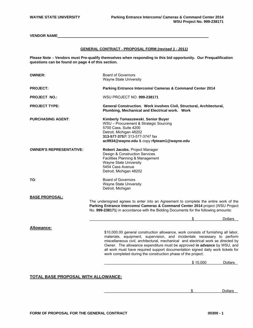
VENDOR NAME
GENERAL CONTRACT - PROPOSAL FORM (revised 1 - 2011) Please Note – Vendors must Pre-qualify themselves when responding to this bid opportunity. Our Prequalification questions can be found on page 4 of this section. OWNER:
Board of Governors Wayne State University
PROJECT:
Parking Entrance Intercoms/ Cameras & Command Center 2014
PROJECT NO.:
WSU PROJECT NO. 999-238171
PROJECT TYPE:
General Construction. Work involves Civil, Structural, Architectural, Plumbing, Mechanical and Electrical work. Work
PURCHASING AGENT:
Kimberly Tomaszewski, Senior Buyer WSU – Procurement & Strategic Sourcing 5700 Cass, Suite 4200 Detroit, Michigan 48202 313-577-3757/ 313-577-3747 fax [email protected] & copy [email protected]
OWNER'S REPRESENTATIVE:
Robert Jacobs, Project Manager Design & Construction Services Facilities Planning & Management Wayne State University 5454 Cass Avenue Detroit, Michigan 48202
TO:
Board of Governors Wayne State University Detroit, Michigan
BASE PROPOSAL: The undersigned agrees to enter into an Agreement to complete the entire work of the
Parking Entrance Intercoms/ Cameras & Command Center 2014 project (WSU Project No. 999-238171) in accordance with the Bidding Documents for the following amounts:
$ Dollars Allowance: $10,000.00 general construction allowance, work consists of furnishing all labor,
materials, equipment, supervision, and incidentals necessary to perform miscellaneous civil, architectural, mechanical and electrical work as directed by Owner. The allowance expenditure must be approved in advance by WSU, and all work must have required support documentation signed daily work tickets for work completed during the construction phase of the project:
$ 10,000 Dollars TOTAL BASE PROPOSAL WITH ALLOWANCE: $ Dollars

WAYNE STATE UNIVERSITY Parking Entrance Intercoms/ Cameras & Command Center 2014 WSU Project No. 999-238171
FORM OF PROPOSAL FOR THE GENERAL CONTRACT 00300 - 2
LAWN REPLACEMENT: The undersigned agrees that, in the event of existing lawn or landscaping damage, due to the Contractor's work, that has not been properly addressed and repaired to the satisfaction of the University, the University may repair/replace the lawn and/or landscaping, and that the expense will be at a unit cost of $10.00 per square yard for lawn, and landscaping at a rate of 1.5 times the cost of said repairs, the full cost of which shall be reimbursed by the contractor.
CONTRACT CHANGE The undersigned agrees to the following pricing formula and rates ORDERS: (revised 4-01-2011) for changes in the contract work:
1. For subcontract work, Contractor's markup for handling, overhead, profit and bonding on subcontractors sell price, shall not exceed 5%. 1.1. For subcontract work that is provided on a time and material basis,
the subcontractor shall be permitted a single markup for handling, overhead, profit and bonding of 5%. When a markup is identified in the subcontractor’s hourly labor rate, additional markup on labor is not permitted.
1.1.1 For changes that are based upon a lump sum value, subcontractor shall provide all labor and material back-ups to ensure that duplicative charges are avoided and authorized mark-ups for OH&P can be confirmed
. 2. For work by his own organization, Contractor's markup for job* and general
overhead, profit and bonding shall not exceed 5% of the net labor** and material costs.
Within 14 days of the project’s contract execution Contractor shall provide to the
Owner; Subcontractor’s hourly labor rate breakdown details. This requirement shall extend to the lowest level of subcontractor participation.
* Job and general overhead includes supervision and executive expenses; use charges
on small tools, scaffolding, blocking, shores, appliances, etc., and other miscellaneous job expenses.
** Net labor cost is the sum of the base wages, fringe benefits established by governing
trade organizations, applicable payroll taxes, and increased expense for contractor's liability insurance (Workman's Compensation, P.L. and P.D.).
TIME OF COMPLETION: (revised 4-01-2011) The Contract is expected to be fully executed on or about 25 calendar days after
successful bidder qualification and recommendation of award. The undersigned agrees to start construction immediately after receipt of a fully executed contract, and to complete the work as follows:
Substantial Completion will be completed no later than September 22, 2014. LIQUIDATED DAMAGES: It is understood and agreed that, if project is not completed within the time specified in the
contract plus any extension of time allowed pursuant thereto, the actual damages sustained by the Owner because of any such delay, will be uncertain and difficult to ascertain, and it is agreed that the reasonable foreseeable value of the use of said project by Owner would be the sum of $1,000.00, One Thousand Dollars per day, and therefore the contractor shall pay as liquidated damages to the Owner the sum of $1,000.00, One Thousand Dollars per day for each day's delay in substantially completing said project beyond the time specified in the Contract and any extensions of time allowed thereunder.
TAXES: The undersigned acknowledges that prices stated above include all applicable taxes of
whatever character or description. Michigan State Sales Tax is applicable to the work. Bidder understands that the Owner reserves the right to reject any or all bids and to waive informalities or irregularities therein.

WAYNE STATE UNIVERSITY Parking Entrance Intercoms/ Cameras & Command Center 2014 WSU Project No. 999-238171
FORM OF PROPOSAL FOR THE GENERAL CONTRACT 00300 - 3
ADDENDA: The undersigned affirms that the cost of all work covered by the following Addenda are included in the lump sum price of this proposal.
Addendum No. Date Addendum No. Date Addendum No. Date Addendum No. Date Addendum No. Date Addendum No. Date Addendum No. Date Addendum No. Date Addendum No. Date Addendum No. Date
CONTRACTOR'S PREQUALIFICATION STATEMENT & QUESTIONNAIRE:
Our Minimum Requirements for Construction Bids are: WSU considers this project: General Construction. Work involves Civil, Structural, Architectural, Plumbing, Mechanical and Electrical work. Work. Criteria Small Project
bid less than $50,000 Medium Project bid between $50,001 and $250,000
Large Project bid between $250,001 and $2 million
Very Large Project bid greater than $2 million
EMR Rating (Experience Modification Rating)
1.0 or Less 1.0 or Less 1.0 or Less 1.0 or Less
Bondable Vendor N.A. Required Required Required Length of Time in Construction Business
2 Years 3 Years 5 Years 5 Years
Demonstrated Experience in Projects Similar in Scope and Price in the last 3 years
1 or more 1 or more 2 or more 3 or more
Unsuccessful Projects on Campus in last 3 years
None Allowed None Allowed None Allowed None Allowed
Failure to comply with Prevailing Wage and/or Project Labor requirements
None Allowed None Allowed None Allowed None Allowed
Withdrawn University Bid (with or without Bond forfeiture) within the last 3 years **
2 or less 2 or less 1 or less 1 or less
Company currently not in Chapter 11 of the US Bankruptcy Code
1 Year 2 Years 3 Years 3 Years
** Withdrawal of a bid is subject to the University suspension policy, for a period up to one year. Contractors must complete the following information to determine their eligibility to participate in this bid. This information is required with your Bid to the University Failure to complete this form in its entirety will result in your bid being disqualified. Check one of the following on the makeup of your company: Corporation Individual

WAYNE STATE UNIVERSITY Parking Entrance Intercoms/ Cameras & Command Center 2014 WSU Project No. 999-238171
FORM OF PROPOSAL FOR THE GENERAL CONTRACT 00300 - 4
Partnership Joint Venture
Other (Explain)
1. How many years has your organization been in business as a contractor?
2. How many years has your organization been in business under its present business name?
3. List states in which your organization is legally qualified to do business.
4. Provide the Name and Address of your Liability Insurance Carrier.
5. What is your current EMR Rating? The minimum requirement is an EMR Rating of 1.0 or less for all projects. Bidders with a rating higher than 1.0 understand that their bid may be disqualified, at the sole discretion of the University.
6. What percentage of work performed on projects are by company employees; excluding any hired subcontracting and
outsourced relationships, for the bid submitted? _______ % 7. What percentage of work performed on your companies behalf are by subcontracted business relationships;
disallowing 1099 contracting work forces, for the bid submitted? _______ % 8. Have you ever failed to complete any work awarded to you? If so, attach a separate sheet of explanation. Include the
name of the Project, the customer, the dates of the work, and the amount of the contract?
9. Have you withdrawn a bid after a University bid opening and/or refused to enter into a contract with the
University upon notification of award within the last 3 years? If so, state the Project Name and Number, and the date of bid submission below.
10. Has any officer or partner of your organization ever been an officer or partner of another organization that
failed to complete a construction contract? If so, attach a separate sheet of explanation.
11. List the construction experience of the principals and superintendents of your company. Name: __________________________________ Title: _____________________________________ _________________________________________________________________________________
Name: __________________________________ Title: _____________________________________ _________________________________________________________________________________
Name: __________________________________ Title: _____________________________________

WAYNE STATE UNIVERSITY Parking Entrance Intercoms/ Cameras & Command Center 2014 WSU Project No. 999-238171
FORM OF PROPOSAL FOR THE GENERAL CONTRACT 00300 - 5
_________________________________________________________________________________
12. List the construction Projects, and approximate dates, when you performed work similar in Scope to this project.
Project: ___________________________________ Owner: __________________________________ Contract Amount: ___________________________ Date Completed: _________________________ Project: ___________________________________ Owner: __________________________________ Contract Amount: ___________________________ Date Completed: _________________________ Project: ___________________________________ Owner: __________________________________ Contract Amount:___________________________ Date Completed: _________________________
13. List the construction Projects, and approximate dates, when you performed work similar in Dollar Amount to this project.
Project:___________________________________ Owner:__________________________________ Contract Amount: __________________________ Date Completed: _________________________ Project: __________________________________ Owner: __________________________________ Contract Amount: __________________________ Date Completed: _________________________ Project: ___________________________________ Owner: __________________________________ Contract Amount: ___________________________ Date Completed: _________________________
14. Is your Company “bondable”? Yes No
15. What is your present bonding capacity? $
16. Who is your bonding agent?
NAME: ADDRESS:
PHONE: ( ) CONTACT:
17. Does your company agree to provide financial reports to the University upon request? Failure to agree may result in
disqualification of your bid. Yes No
18. Does your company agree that all of the Terms and Conditions of this RFP and Vendor’s Response Proposal become part of any ensuing agreement? Yes No
19. Does your company agree to execute a contract containing the clauses shown in Section 00500 “Agreement
Between Contractor and Owner for Construction”? Yes No
If “No”, clearly note any exceptions to any information contained in the contract documents and include with your proposal.

WAYNE STATE UNIVERSITY Parking Entrance Intercoms/ Cameras & Command Center 2014 WSU Project No. 999-238171
FORM OF PROPOSAL FOR THE GENERAL CONTRACT 00300 - 6
20. Did your company quote based upon Prevailing Wage Rates? Yes No Note: Contractors submitting proposals for this project may, at the discretion of the University, be required to submit references including contact information to be used to assist in the post bid evaluation process for the subject project ACKNOWLEDGEMENT OF The undersigned has read and understands the minimum qualifications MINIMUM QUALIFICATIONS: for University construction projects, and has completed the Prequalification
section completely and accurately. The undersigned understands that a contractor, who fails to meet the minimum qualifications in the category identified for this project, will be disqualified from consideration for the project.
ACCEPTANCE OF PROPOSAL: The undersigned agrees to execute a Contract, being the Wayne State University
standard form titled "Agreement Between Contractor and Owner for Construction" (see section 00500 of the bid documents), provided that we are notified of the acceptance of our Proposal within sixty (60) days of the date set for the opening thereof.
The undersigned below understands that the bid will be disqualified if the Prequalification information above is not completed in its entirety. NAME OF COMPANY: OFFICE ADDRESS: PHONE NUMBER: DATE FAX NUMBER: SIGNED BY: Signature (Please print or type name here) TITLE EMAIL ADDRESS: @

WAYNE STATE UNIVERSITY Parking Entrance Intercoms/ Cameras & Command Center 2014 WSU Project No. 999-238171
PREVAILING WAGE RATE SCHEDULE 00410 - 1
PREVAILING WAGE RATE SCHEDULE (revised 4-05-2010)
A. See also Page 00100-4 Section 12.B B. Wayne State University requires all project contractors, including subcontractors, who provide labor on University
projects to compensate at a rate no less than prevailing wage rates.
C. The rates of wages and fringe benefits to be paid to each class of laborers and mechanics by each VENDOR and subcontractor(s) (if any) shall be not less than the wage and fringe benefit rates prevailing in Wayne County, Michigan, as determined by the United States Secretary of Labor. Individually contracted labor commonly referred to as “1099 Workers” and subcontractors using 1099 workers are not acceptable for work related to this project.
D. To maintain compliance with State of Michigan Ordinances, Certified Payroll must be provided for each of the contractor’s or subcontractor’s payroll periods for work performed on this project. Certified Payroll should accompany all Pay Applications. Failure to provide certified payroll will constitute breach of contract, and pay applications will be returned unpaid, and remain so until satisfactory supporting documents are provided.
A Prevailing Wage Rate Schedule has been issued from the State of Michigan that is enclosed in this section Additional information can be found on the University Procurement & Strategic Sourcing’s web site at the following URL address:
http://purchasing.wayne.edu/vendors/wage-rates.php
If you have any questions, or require rates for additional classifications, please contact:
Michigan Department of Consumer & Industry Services, Bureau of Safety and Regulation, Wage and Hour Division, 7150 Harris Drive, P.O. Box 30476, Lansing, Michigan 48909-7976
http://www.michigan.gov/dleg/0,1607,7-154-27673_27706---,00.html
F. Wayne State University's Prevailing Wage Requirements:
When compensation will be paid under prevailing wage requirements, the University shall require the following:
A. The contractor shall obtain and keep posted on the work site, in a conspicuous place, a copy of all current prevailing wage and fringe benefit rates.
B. The contractor shall obtain and keep an accurate record showing the name and occupation of and the actual
wages and benefits paid to each laborer and mechanic employed in connection with this contract.
C. The contractor shall submit a completed certified payroll document [U.S. Department of Labor Form WH 347] verifying and confirming the prevailing wage and benefits rates for all employees and subcontractors for each payroll period for work performed on this project. The contractor shall include copies of pay stubs for all employee or contract labor payments related to Wayne State University work. The certified payroll form can be downloaded from the Department of Labor website at http://www.dol.gov/whd/forms/wh347.pdf.
D. A properly executed sworn statement is required from all tiers of contractors, sub-contractors and suppliers
which provide services or product of $1,000.00 or greater. Sworn statements must accompany applications for payment. All listed parties on a sworn statement and as a subcontractor must submit Partial or Full Conditional Waivers for the amounts invoiced on the payment application. A copy of the acceptable WSU Sworn Statement and Waiver will be provided to the awarded contractor.
WAYNE STATE UNIVERSITY Parking Entrance Intercoms/ Cameras & Command Center 2014 WSU Project No. 999-238171
PREVAILING WAGE RATE SCHEDULE 00410 - 2
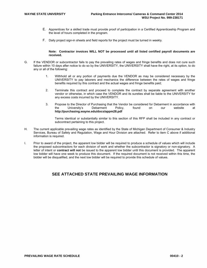
E. Apprentices for a skilled trade must provide proof of participation in a Certified Apprenticeship Program and the level of hours completed in the program.
F. Daily project sign-in sheets and field reports for the project must be turned in weekly.
Note: Contractor invoices WILL NOT be processed until all listed certified payroll documents are received.
G. If the VENDOR or subcontractor fails to pay the prevailing rates of wages and fringe benefits and does not cure such
failure within 10 days after notice to do so by the UNIVERSITY, the UNIVERSITY shall have the right, at its option, to do any or all of the following:
1. Withhold all or any portion of payments due the VENDOR as may be considered necessary by the
UNIVERSITY to pay laborers and mechanics the difference between the rates of wages and fringe benefits required by this contract and the actual wages and fringe benefits paid;
2. Terminate this contract and proceed to complete the contract by separate agreement with another
vendor or otherwise, in which case the VENDOR and its sureties shall be liable to the UNIVERSITY for any excess costs incurred by the UNIVERSITY.
3. Propose to the Director of Purchasing that the Vendor be considered for Debarment in accordance with
the University’s Debarment Policy, found on our website at http://purchasing.wayne.edu/docs/appm28.pdf
Terms identical or substantially similar to this section of this RFP shall be included in any contract or
subcontract pertaining to this project. H. The current applicable prevailing wage rates as identified by the State of Michigan Department of Consumer & Industry
Services, Bureau of Safety and Regulation, Wage and Hour Division are attached. Refer to item C above if additional information is required.
I. Prior to award of the project, the apparent low bidder will be required to produce a schedule of values which will include
the proposed subcontractors for each division of work and whether the subcontractor is signatory or non-signatory. A letter of intent or contract will not be issued to the apparent low bidder until this document is provided. The apparent low bidder will have one week to produce this document. If the required document is not received within this time, the bidder will be disqualified, and the next low bidder will be required to provide this schedule of values.
SEE ATTACHED STATE PREVAILING WAGE INFORMATION

WAYNE STATE UNIVERSITY Parking Entrance Intercoms/ Cameras & Command Center 2014 WSU Project No. 999-238171
PREVAILING WAGE RATE SCHEDULE 00410 - 3
State of Michigan [email protected] Official Request #: 807 Requestor: Wayne State University Project Description: Parking Entrance - Intercoms/Cameras & Command Center Addition/Expansion Project Number: 999-238171
Wayne County Official 2014 Prevailing Wage Rates for State Funded Projects Issue Date: 5/8/2014 Contract must be awarded by: 8/6/2014 Page 1 of 29 Classification Last Straight Time and a Double Overtime Name Description Updated Hourly Half Time Provision ===================================================================================================
Asbestos & Lead Abatement Laborer Asbestos & Lead Abatement Laborer MLDC $39.75 $53.04 $66.32 H H H X X X X D Y 4 ten hour days @ straight time allowed Monday-Saturday, 8/14/2013 must be consecutive calendar days
Asbestos & Lead Abatement, Hazardous Material Handler Asbestos and Lead Abatement, Hazardous Material Handler AS207 $39.75 $53.08 $66.40 H H H X X X X D Y 9/16/2013 4 ten hour days @ straight time allowed Monday-Saturday,
Boilermaker Boilermaker BO169 $54.70 $81.08 $107.45 H H H H H H H D Y 8/14/2009 Apprentice Rates: 1st 6 months $40.31 $59.49 $78.67 2nd 6 months $41.45 $61.21 $80.95 3rd 6 months $42.57 $62.88 $83.19 4th 6 months $43.69 $64.57 $85.43 5th 6 months $44.81 $66.24 $87.67 6th 6 months $49.53 $73.40 $97.26 7th 6 months $49.32 $73.01 $96.69 8th 6 months $51.58 $76.40 $101.21
Official Request #: 807 Official Rate Schedule Requestor: Wayne State University Every contractor and subcontractor shall keep posted Project Description: Parking Entrance - Intercoms/Cameras & Command Center on the construction site, in a conspicuous place, a copy of all prevailing wage and fringe benefit rates Project Number: 999-238171 prescribed in a contract. County: Wayne Page 1 of 29

WAYNE STATE UNIVERSITY Parking Entrance Intercoms/ Cameras & Command Center 2014 WSU Project No. 999-238171
PREVAILING WAGE RATE SCHEDULE 00410 - 4
Official 2014 Prevailing Wage Rates for State Funded Projects Issue Date: 5/8/2014 Contract must be awarded by: 8/6/2014 Page 2 of 29 Classification Last Straight Time and a Double Overtime Name Description Updated Hourly Half Time Provision ===================================================================================================
Bricklayer Bricklayer, stone mason, pointer, cleaner, caulker BR1 $51.93 $77.90 $103.86 H H D H D D D D N 9/3/2013 Between October 1 and April 30, if lost time occurs due to inclement weather, Saturday may be worked as a make- up day @ straight time until forty hours are worked.
Apprentice Rates: First 6 months $31.54 $47.32 $63.08 2nd 6 months $33.39 $50.10 $66.78 3rd 6 months $35.24 $52.87 $70.48 4th 6 months $37.09 $55.64 $74.18 5th 6 months $38.94 $58.42 $77.88 6th 6 months $40.79 $61.20 $81.58 7th 6 months $42.64 $63.97 $85.28 8th 6 months $44.49 $66.74 $88.98
Carpenter Diver CA 687 D $63.30 $91.30 $119.29 X X H X X H H D Y Four 10s allowed M-Sat; double time due when over 12 10/9/2013 hours worked per day
Carpet and Resilient Floor Layer, (does not include CA1045 $48.14 $68.71 $89.27 X X H X X X X D Y installation of prefabricated formica & parquet flooring 11/6/2013 which is to be paid carpenter rate)
Apprentice Rates: 1st 6 months $23.56 $31.84 $40.11 2nd 6 months $27.57 $37.85 $48.13 3rd 6 months $29.64 $40.96 $52.27 4th 6 months $31.69 $44.03 $56.37 5th 6 months $33.75 $47.12 $60.49 6th 6 months $35.80 $50.20 $64.59 7th 6 months $37.86 $53.28 $68.71 8th 6 months $39.91 $56.36 $72.81
Official Request #: 807 Official Rate Schedule Requestor: Wayne State University Every contractor and subcontractor shall keep posted Project Description: Parking Entrance - Intercoms/Cameras & Command Center on the construction site, in a conspicuous place, a copy of all prevailing wage and fringe benefit rates Project Number: 999-238171 prescribed in a contract. County: Wayne Page 2 of 29

WAYNE STATE UNIVERSITY Parking Entrance Intercoms/ Cameras & Command Center 2014 WSU Project No. 999-238171
PREVAILING WAGE RATE SCHEDULE 00410 - 5
Official 2014 Prevailing Wage Rates for State Funded Projects Issue Date: 5/8/2014 Contract must be awarded by: 8/6/2014 Page 3 of 29 Classification Last Straight Time and a Double Overtime Name Description Updated Hourly Half Time Provision =================================================================================================== Carpenter-four 10s allowed Mon-Sat; double time due when CA687Z1 $53.89 $77.19 $100.49 X X H X X H H D Y over 12 hours worked per day 10/1/2013
Apprentice Rates: 1st year $32.92 $45.74 $58.55 3rd 6 months $35.26 $49.25 $63.23 4th 6 months $37.58 $52.73 $67.87 5th 6 months $39.92 $56.23 $72.55 6th 6 months $42.24 $59.72 $77.19 7th 6 months $44.57 $63.22 $81.85 8th 6 months $46.91 $66.72 $86.53
Piledriver CA687Z1P $53.89 $77.19 $100.49 X X H X X H H D Y Four 10s allowed Monday-Saturday; double time due when 10/1/2013 over 12 hours worked per day
Apprentice Rates: 1st 6 months $32.92 $45.74 $58.55 2nd 6 months $37.58 $52.73 $67.87 3rd 6 months $42.24 $59.72 $77.19 4th 6 months $46.91 $66.72 $86.53
Cement Mason Cement Mason br1cm $49.30 $70.06 $90.81 X X H H H H H D N 9/3/2013 Apprentice Rates: 1st 6 months $28.71 $38.90 $49.09 2nd 6 months $30.74 $41.93 $53.12 3rd 6 months $34.79 $47.99 $61.19 4th 6 months $38.85 $54.05 $69.23 5th 6 months $40.88 $57.07 $73.25 6th 6 months $44.93 $63.11 $81.30
Cement Mason CE514 $46.30 $64.89 $83.48 H H D H H H H D N 11/10/2011 Apprentice Rates: 1st 6 months $26.77 $36.07 $45.36 2nd 6 months $28.68 $38.91 $49.13 3rd 6 months $32.50 $44.59 $56.66 4th 6 months $36.32 $50.26 $64.19 5th 6 months $38.24 $53.11 $67.98 6th 6 months $42.06 $58.79 $75.51
Official Request #: 807 Official Rate Schedule Requestor: Wayne State University Every contractor and subcontractor shall keep posted Project Description: Parking Entrance - Intercoms/Cameras & Command Center on the construction site, in a conspicuous place, a copy of all prevailing wage and fringe benefit rates Project Number: 999-238171 prescribed in a contract. County: Wayne Page 3 of 29
WAYNE STATE UNIVERSITY Parking Entrance Intercoms/ Cameras & Command Center 2014 WSU Project No. 999-238171
PREVAILING WAGE RATE SCHEDULE 00410 - 6
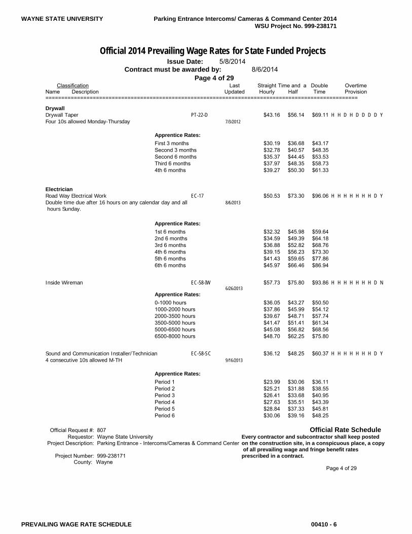
Official 2014 Prevailing Wage Rates for State Funded Projects Issue Date: 5/8/2014 Contract must be awarded by: 8/6/2014 Page 4 of 29 Classification Last Straight Time and a Double Overtime Name Description Updated Hourly Half Time Provision ===================================================================================================
Drywall Drywall Taper PT-22-D $43.16 $56.14 $69.11 H H D H D D D D Y Four 10s allowed Monday-Thursday 7/3/2012
Apprentice Rates: First 3 months $30.19 $36.68 $43.17 Second 3 months $32.78 $40.57 $48.35 Second 6 months $35.37 $44.45 $53.53 Third 6 months $37.97 $48.35 $58.73 4th 6 months $39.27 $50.30 $61.33
Electrician Road Way Electrical Work EC-17 $50.53 $73.30 $96.06 H H H H H H H D Y Double time due after 16 hours on any calendar day and all 8/6/2013 hours Sunday.
Apprentice Rates: 1st 6 months $32.32 $45.98 $59.64 2nd 6 months $34.59 $49.39 $64.18 3rd 6 months $36.88 $52.82 $68.76 4th 6 months $39.15 $56.23 $73.30 5th 6 months $41.43 $59.65 $77.86 6th 6 months $45.97 $66.46 $86.94
Inside Wireman EC-58-IW $57.73 $75.80 $93.86 H H H H H H H D N 6/26/2013 Apprentice Rates: 0-1000 hours $36.05 $43.27 $50.50 1000-2000 hours $37.86 $45.99 $54.12 2000-3500 hours $39.67 $48.71 $57.74 3500-5000 hours $41.47 $51.41 $61.34 5000-6500 hours $45.08 $56.82 $68.56 6500-8000 hours $48.70 $62.25 $75.80
Sound and Communication Installer/Technician EC-58-SC $36.12 $48.25 $60.37 H H H H H H H D Y 4 consecutive 10s allowed M-TH 9/16/2013
Apprentice Rates: Period 1 $23.99 $30.06 $36.11 Period 2 $25.21 $31.88 $38.55 Period 3 $26.41 $33.68 $40.95 Period 4 $27.63 $35.51 $43.39 Period 5 $28.84 $37.33 $45.81 Period 6 $30.06 $39.16 $48.25
Official Request #: 807 Official Rate Schedule Requestor: Wayne State University Every contractor and subcontractor shall keep posted Project Description: Parking Entrance - Intercoms/Cameras & Command Center on the construction site, in a conspicuous place, a copy of all prevailing wage and fringe benefit rates Project Number: 999-238171 prescribed in a contract. County: Wayne Page 4 of 29

WAYNE STATE UNIVERSITY Parking Entrance Intercoms/ Cameras & Command Center 2014 WSU Project No. 999-238171
PREVAILING WAGE RATE SCHEDULE 00410 - 7
Official 2014 Prevailing Wage Rates for State Funded Projects Issue Date: 5/8/2014 Contract must be awarded by: 8/6/2014 Page 5 of 29 Classification Last Straight Time and a Double Overtime Name Description Updated Hourly Half Time Provision ===================================================================================================
Elevator Constructor Elevator Constructor EL 36 $56.46 $94.99 D D D D D D D D Y Elevator Constructor 8/7/2007
Apprentice Rates: 1st Year Apprentice $37.74 $58.93 2nd Year Apprentice $41.90 $66.94 3rd Year Apprentice $43.98 $70.95 4th Year Apprentice $48.14 $78.96
Glazier Glazier GL-357 $46.21 $64.51 $82.80 H H H H H H H D Y If a four 10 hour day workweek is scheduled, four 10s 7/3/2012 must be consecutive, M-F.
Apprentice Rates: 1st 6 months $31.63 $42.64 $53.64 2nd 6 months $33.09 $44.83 $56.56 3rd 6 months $36.00 $49.19 $62.38 4th 6 months $37.46 $51.39 $65.30 5th 6 months $38.92 $53.57 $68.22 6th 6 months $40.38 $55.77 $71.14 7th 6 months $41.84 $57.95 $74.06 8th 6 months $44.75 $62.32 $79.88
Heat and Frost Insulator Spray Insulation AS25S $20.14 $29.14 H H H H H H H H N 3/5/2007
Heat and Frost Insulator and Asbestos Worker Heat and Frost Insulators and Asbestos Workers AS25 $60.25 $76.00 $91.74 H H H H H H H D Y Four 10s must be worked for a minimum of 2 weeks 1/29/2014 consecutively, Monday thru Thursday. All hours worked in excess of 10 will be paid at double time. All hours worked on the fifth day, Monday thru Friday will paid at time and one-half.
Apprentice Rates: 1st Year $46.08 $54.74 $63.40 2nd Year $49.23 $59.46 $69.70 3rd Year $50.80 $61.82 $72.84 4th Year $53.95 $66.54 $79.14
Official Request #: 807 Official Rate Schedule Requestor: Wayne State University Every contractor and subcontractor shall keep posted Project Description: Parking Entrance - Intercoms/Cameras & Command Center on the construction site, in a conspicuous place, a copy of all prevailing wage and fringe benefit rates Project Number: 999-238171 prescribed in a contract. County: Wayne Page 5 of 29
WAYNE STATE UNIVERSITY Parking Entrance Intercoms/ Cameras & Command Center 2014 WSU Project No. 999-238171
PREVAILING WAGE RATE SCHEDULE 00410 - 8
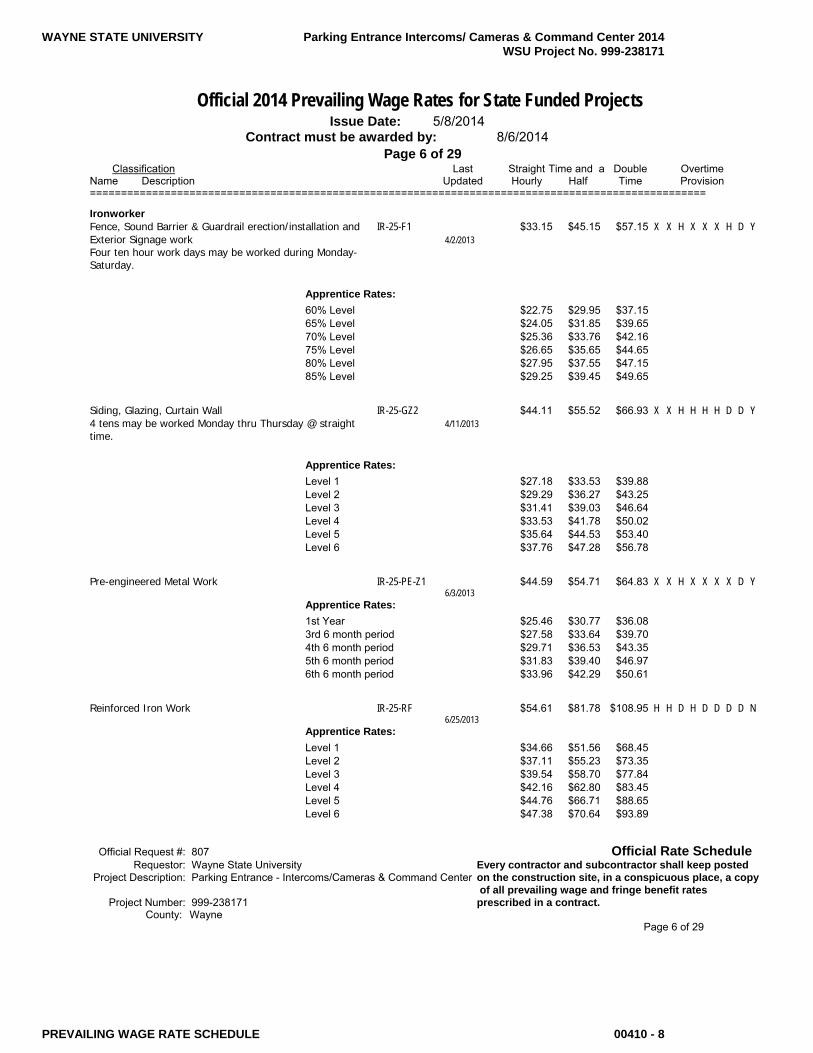
Official 2014 Prevailing Wage Rates for State Funded Projects Issue Date: 5/8/2014 Contract must be awarded by: 8/6/2014 Page 6 of 29 Classification Last Straight Time and a Double Overtime Name Description Updated Hourly Half Time Provision ===================================================================================================
Ironworker Fence, Sound Barrier & Guardrail erection/installation and IR-25-F1 $33.15 $45.15 $57.15 X X H X X X H D Y Exterior Signage work 4/2/2013 Four ten hour work days may be worked during Monday- Saturday.
Apprentice Rates: 60% Level $22.75 $29.95 $37.15 65% Level $24.05 $31.85 $39.65 70% Level $25.36 $33.76 $42.16 75% Level $26.65 $35.65 $44.65 80% Level $27.95 $37.55 $47.15 85% Level $29.25 $39.45 $49.65
Siding, Glazing, Curtain Wall IR-25-GZ2 $44.11 $55.52 $66.93 X X H H H H D D Y 4 tens may be worked Monday thru Thursday @ straight 4/11/2013 time.
Apprentice Rates: Level 1 $27.18 $33.53 $39.88 Level 2 $29.29 $36.27 $43.25 Level 3 $31.41 $39.03 $46.64 Level 4 $33.53 $41.78 $50.02 Level 5 $35.64 $44.53 $53.40 Level 6 $37.76 $47.28 $56.78
Pre-engineered Metal Work IR-25-PE-Z1 $44.59 $54.71 $64.83 X X H X X X X D Y 6/3/2013 Apprentice Rates: 1st Year $25.46 $30.77 $36.08 3rd 6 month period $27.58 $33.64 $39.70 4th 6 month period $29.71 $36.53 $43.35 5th 6 month period $31.83 $39.40 $46.97 6th 6 month period $33.96 $42.29 $50.61
Reinforced Iron Work IR-25-RF $54.61 $81.78 $108.95 H H D H D D D D N 6/25/2013 Apprentice Rates: Level 1 $34.66 $51.56 $68.45 Level 2 $37.11 $55.23 $73.35 Level 3 $39.54 $58.70 $77.84 Level 4 $42.16 $62.80 $83.45 Level 5 $44.76 $66.71 $88.65 Level 6 $47.38 $70.64 $93.89
Official Request #: 807 Official Rate Schedule Requestor: Wayne State University Every contractor and subcontractor shall keep posted Project Description: Parking Entrance - Intercoms/Cameras & Command Center on the construction site, in a conspicuous place, a copy of all prevailing wage and fringe benefit rates Project Number: 999-238171 prescribed in a contract. County: Wayne Page 6 of 29

WAYNE STATE UNIVERSITY Parking Entrance Intercoms/ Cameras & Command Center 2014 WSU Project No. 999-238171
PREVAILING WAGE RATE SCHEDULE 00410 - 9
Official 2014 Prevailing Wage Rates for State Funded Projects Issue Date: 5/8/2014 Contract must be awarded by: 8/6/2014 Page 7 of 29 Classification Last Straight Time and a Double Overtime Name Description Updated Hourly Half Time Provision =================================================================================================== Rigging Work IR-25-RIG $60.28 $90.26 $120.24 H H H H H H H D N 6/25/2013 Apprentice Rates: Level 1& 2 $34.93 $52.39 $69.86 Level 3 $37.80 $56.71 $75.60 Level 4 $40.66 $60.99 $81.32 Level 5 $43.53 $65.29 $87.06 Level 6 $46.41 $69.62 $92.82
Decking IR-25-SD $52.24 $78.08 $103.92 X X H H H H D D Y 4 tens may be worked Monday thru Thursday @ straight 6/25/2013 time. If bad weather, Friday may be a make up day. If holiday celebrated on a Monday, 4 10s may be worked Tuesday thru Friday. Work in excess of 12 hours per day must be paid @ double time.
Structural, ornamental, conveyor, welder and pre-cast IR-25-STR $60.41 $90.34 $120.26 H H H H H H D D Y 4 tens may be worked Monday thru Thursday @ straight 6/25/2013 time. If bad weather, Friday may be a make up day. If holiday celebrated on a Monday, 4 10s may be worked Tuesday thru Friday. Work in excess of 12 hours per day must be paid @ double time.
Apprentice Rates: Levels 1 & 2 $35.06 $52.64 $69.98 Level 3 $37.89 $56.52 $75.14 Level 4 $40.71 $60.74 $80.78 Level 5 $43.54 $65.37 $86.94 Level 6 $46.37 $69.24 $92.10 Level 7 $49.19 $73.47 $97.74 Level 8 $52.02 $77.71 $103.40
Industrial Door erection & construction IR-25-STR-D $40.97 $61.13 $81.29 H H H H H H D D Y 6/27/2013
Official Request #: 807 Official Rate Schedule Requestor: Wayne State University Every contractor and subcontractor shall keep posted Project Description: Parking Entrance - Intercoms/Cameras & Command Center on the construction site, in a conspicuous place, a copy of all prevailing wage and fringe benefit rates Project Number: 999-238171 prescribed in a contract. County: Wayne Page 7 of 29

WAYNE STATE UNIVERSITY Parking Entrance Intercoms/ Cameras & Command Center 2014 WSU Project No. 999-238171
PREVAILING WAGE RATE SCHEDULE 00410 - 10
Official 2014 Prevailing Wage Rates for State Funded Projects Issue Date: 5/8/2014 Contract must be awarded by: 8/6/2014 Page 8 of 29 Classification Last Straight Time and a Double Overtime Name Description Updated Hourly Half Time Provision ===================================================================================================
Laborer Construction Laborer, Demolition Laborer, Mason L33401-A-CC $43.54 $61.94 $80.33 H H H H H H H D Y Tender,Carpenter Tender, Drywall Handler, Concrete 7/15/2013 Laborer, Cement Finisher Tender, Concrete Chute, and Concrete Bucket Handler If conditions beyond the employer/employee's control prevent one or more hours of working during Mon-Fri, the employer may choose to work up to 10 hour straight time weekdays. Work may be scheduled up to 10 hours per Mon-Fri for the purpose of reaching 40 hours @ straight time. Make up days may also include 8 hours of work on Saturdays @ straight time.
Apprentice Rates: 0-1,000 work hours $37.60 $53.03 $68.45 1,001 - 2,000 work hours $38.79 $54.81 $70.83 2,001 - 3,000 work hours $39.98 $56.60 $73.21 3,001 - 4,000 work hours $42.35 $60.15 $77.95
Signal Man (on sewer & caisson work), Air, Electric or L33401-B-SB $43.80 $62.33 $80.85 H H H H H H H D Y Gasoline Tool Operator, Concrete Vibrator Operator, 7/16/2013 Acetylene Torch & Air Hammer Operator; Scaffold Builder, Caisson Worker If conditions beyond the employer/employee's control prevent one or more hours of working during Mon-Fri, the employer may choose to work up to 10 hour straight time weekdays. Work may be scheduled up to 10 hours per Mon-Fri for the purpose of reaching 40 hours @ straight time. Make up days may also include 8 hours of work on Saturdays @ straight time.
Furnace Battery Heater Tender, Burning Bar & Oxy- L33401-D-HH $44.04 $62.69 $81.33 H H H H H H H D Y Acetylene Gun 7/16/2013 If conditions beyond the employer/employee's control prevent one or more hours of working during Mon-Fri, the employer may choose to work up to 10 hour straight time weekdays. Work may be scheduled up to 10 hours per Mon-Fri for the purpose of reaching 40 hours @ straight time. Make up days may also include 8 hours of work on
Saturdays @ straight time.
Official Request #: 807 Official Rate Schedule Requestor: Wayne State University Every contractor and subcontractor shall keep posted Project Description: Parking Entrance - Intercoms/Cameras & Command Center on the construction site, in a conspicuous place, a copy of all prevailing wage and fringe benefit rates Project Number: 999-238171 prescribed in a contract. County: Wayne Page 8 of 29

WAYNE STATE UNIVERSITY Parking Entrance Intercoms/ Cameras & Command Center 2014 WSU Project No. 999-238171
PREVAILING WAGE RATE SCHEDULE 00410 - 11
Official 2014 Prevailing Wage Rates for State Funded Projects Issue Date: 5/8/2014 Contract must be awarded by: 8/6/2014 Page 9 of 29 Classification Last Straight Time and a Double Overtime Name Description Updated Hourly Half Time Provision =================================================================================================== Expediter Man, Top Man and/or Bottom Man (Blast Furnace L33401-E-EX $44.79 $63.81 $82.83 H H H H H H H D Y Work or Battery Work) 7/16/2013 If conditions beyond the employer/employee's control prevent one or more hours of working during Mon-Fri, the employer may choose to work up to 10 hour straight time weekdays. Work may be scheduled up to 10 hours per Mon-Fri for the purpose of reaching 40 hours @ straight time. Make up days may also include 8 hours of work on Saturdays @ straight time.
Cleaner/Sweeper Laborer; Furniture Laborer L33401-F-CL $38.09 $53.76 $69.43 H H H H H H H D Y 7/16/2013 If conditions beyond the employer/employee's control prevent one or more hours of working during Mon-Fri, the employer may choose to work up to 10 hour straight time weekdays. Work may be scheduled up to 10 hours per Mon-Fri for the purpose of reaching 40 hours @ straight time. Make up days may also include 8 hours of work on Saturdays @ straight time.
Lansing Burner, Blaster & Powder Man; Air, Electric or L334C $44.29 $63.06 $81.83 X X H X H H H D Y Gasoline Tool Operator (Blast Furance Work or Battery 7/16/2013 Work)
Plasterer Tender, Plastering Machine Operator LPT-1 $43.54 $61.94 $80.33 X X H H H H H D Y 10/25/2013 If conditions beyond the employer/employee's control prevent one or more hours of working during Mon-Fri, the employer may choose to work up to 10 hour straight time weekdays. Work may be scheduled up to 10 hours per Mon-Fri for the purpose of reaching 40 hours @ straight time. Make up days may also include 8 hours of work on Saturdays @ straight time.
Apprentice Rates: 0 - 1,000 hours $37.60 $53.03 $68.45 1,001 - 2,000 hours $38.79 $54.81 $70.83 2,001 - 3,000 hours $39.98 $56.60 $73.21
3,001 - 4,000 hours $42.35 $60.15 $77.95
Official Request #: 807 Official Rate Schedule Requestor: Wayne State University Every contractor and subcontractor shall keep posted Project Description: Parking Entrance - Intercoms/Cameras & Command Center on the construction site, in a conspicuous place, a copy of all prevailing wage and fringe benefit rates Project Number: 999-238171 prescribed in a contract. County: Wayne Page 9 of 29

WAYNE STATE UNIVERSITY Parking Entrance Intercoms/ Cameras & Command Center 2014 WSU Project No. 999-238171
PREVAILING WAGE RATE SCHEDULE 00410 - 12
Official 2014 Prevailing Wage Rates for State Funded Projects Issue Date: 5/8/2014 Contract must be awarded by: 8/6/2014 Page 10 of 29 Classification Last Straight Time and a Double Overtime Name Description Updated Hourly Half Time Provision ===================================================================================================
Laborer - Hazardous Class A performing work in conjunction with site LHAZ-Z1-A $43.54 $61.94 $80.33 H H H H H H H D Y preparation and other preliminary work prior to actual 11/1/2013 removal, handling, or containment of hazardous waste substances not requiring use of personal protective equipment required by state or federal regulations; or a laborer performing work in conjunction with the removal, handling, or containment of hazardous waste substances when use of personal protective equipment level "D" is required.
Apprentice Rates: 0-1,000 work hours $37.60 $53.03 $68.45 1,001-2,000 work hours $38.79 $54.81 $70.83 2,001-3,000 work hours $39.98 $56.60 $73.21 3,001-4,000 work hours $42.35 $60.15 $77.95
Class B performing work in conjunction with the removal, LHAZ-Z1-B $44.54 $63.44 $82.33 H H H H H H H D Y handling, or containment of hazardous waste substances 11/4/2013 when the use of personal protective equipment levels "A", "B" or "C" is required.
Apprentice Rates: 0-1,000 work hours $38.36 $54.17 $69.97 1,001-2,000 work hours $39.59 $56.01 $72.43 2,001-3,000 work hours $40.83 $57.87 $74.91 3,001-4,000 work hours $43.30 $61.58 $79.85
Laborer Underground - Tunnel, Shaft & Caisson Class I - Tunnel, shaft and caisson laborer, dump man, LAUCT-Z1-1 $37.87 $48.66 $59.44 X X X X X X X D Y shanty man, hog house tender, testing man (on gas), and 9/6/2013 watchman.
Apprentice Rates: 0-1,000 work hours $33.05 $41.43 $49.80 1,001-2,000 work hours $34.02 $42.88 $51.74 2,001-3,000 work hours $34.98 $44.32 $53.66 3,001-4,000 work hours $36.91 $47.21 $57.52
Official Request #: 807 Official Rate Schedule Requestor: Wayne State University Every contractor and subcontractor shall keep posted Project Description: Parking Entrance - Intercoms/Cameras & Command Center on the construction site, in a conspicuous place, a copy of all prevailing wage and fringe benefit rates Project Number: 999-238171 prescribed in a contract. County: Wayne Page 10 of 29

WAYNE STATE UNIVERSITY Parking Entrance Intercoms/ Cameras & Command Center 2014 WSU Project No. 999-238171
PREVAILING WAGE RATE SCHEDULE 00410 - 13
Official 2014 Prevailing Wage Rates for State Funded Projects Issue Date: 5/8/2014 Contract must be awarded by: 8/6/2014 Page 11 of 29 Classification Last Straight Time and a Double Overtime Name Description Updated Hourly Half Time Provision =================================================================================================== Class II - Manhole, headwall, catch basin builder, bricklayer LAUCT-Z1-2 $37.98 $48.82 $59.66 X X X X X X X D Y tender, mortar man, material mixer, fence erector, and 9/6/2013 guard rail builder.
Apprentice Rates: 0-1,000 work hours $33.14 $41.56 $49.98 1,001-2,000 work hours $34.10 $43.00 $51.90 2,001-3,000 work hours $35.07 $44.45 $53.84 3,001-4,000 work hours $37.01 $47.37 $57.72
Class III - Air tool operator (jack hammer man, bush LAUCT-Z1-3 $38.04 $48.91 $59.78 X X X X X X X D Y hammer man and grinding man), first bottom man, second 9/6/2013 bottom man, cage tender, car pusher, carrier man, concrete man, concrete form man, concrete repair man, cement invert laborer, cement finisher, concrete shoveler, conveyor man, floor man, gasoline and electric tool operator, gunnite man, grout operator, welder, heading dinky man, inside lock tender, pea gravel operator, pump man, outside lock tender, scaffold man, top signal man, switch man, track man, tugger man, utility man, vibrator man, winch operator, pipe jacking man, wagon drill and air track operator and concrete saw operator (under 40 h.p.).
Apprentice Rates: 0-1,000 work hours $33.18 $41.62 $50.06 1,001-2,000 work hours $34.15 $43.07 $52.00 2,001-3,000 work hours $35.12 $44.53 $53.94 3,001-4,000 work hours $37.07 $47.45 $57.84
Class IV - Tunnel, shaft and caisson mucker, bracer man, LAUCT-Z1-4 $38.22 $49.18 $60.14 X X X X X X X D Y liner plate man, long haul dinky driver and well point man. 9/6/2013
Apprentice Rates: 0-1,000 work hours $33.32 $41.83 $50.34 1,001-2,000 work hours $34.30 $43.30 $52.30 2,001-3,000 work hours $35.28 $44.77 $54.26 3,001-4,000 work hours $37.24 $47.71 $58.18
Class V - Tunnel, shaft and caisson miner, drill runner, LAUCT-Z1-5 $38.47 $49.56 $60.64 X X X X X X X D Y keyboard operator, power knife operator, reinforced steel 9/6/2013 or mesh man (e.g. wire mesh, steel mats, dowel bars)
Apprentice Rates: 0-1,000 work hours $33.50 $42.10 $50.70 1,001-2,000 work hours $34.50 $43.60 $52.70 2,001-3,000 work hours $35.49 $45.09 $54.68 3,001-4,000 work hours $37.48 $48.07 $58.66 Official Request #: 807 Official Rate Schedule Requestor: Wayne State University Every contractor and subcontractor shall keep posted Project Description: Parking Entrance - Intercoms/Cameras & Command Center on the construction site, in a conspicuous place, a copy of all prevailing wage and fringe benefit rates Project Number: 999-238171 prescribed in a contract. County: Wayne Page 11 of 29
WAYNE STATE UNIVERSITY Parking Entrance Intercoms/ Cameras & Command Center 2014 WSU Project No. 999-238171
PREVAILING WAGE RATE SCHEDULE 00410 - 14
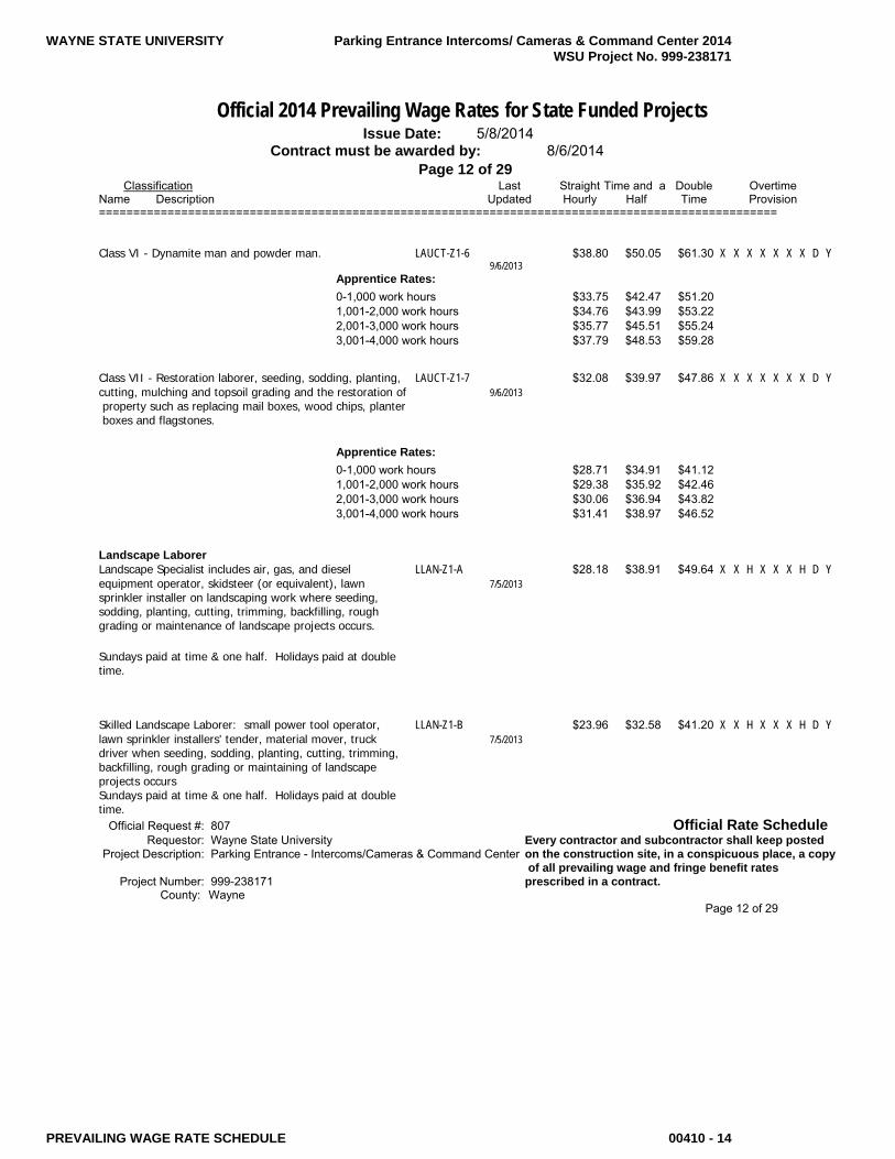
Official 2014 Prevailing Wage Rates for State Funded Projects Issue Date: 5/8/2014 Contract must be awarded by: 8/6/2014 Page 12 of 29 Classification Last Straight Time and a Double Overtime Name Description Updated Hourly Half Time Provision ===================================================================================================
Class VI - Dynamite man and powder man. LAUCT-Z1-6 $38.80 $50.05 $61.30 X X X X X X X D Y 9/6/2013 Apprentice Rates: 0-1,000 work hours $33.75 $42.47 $51.20 1,001-2,000 work hours $34.76 $43.99 $53.22 2,001-3,000 work hours $35.77 $45.51 $55.24 3,001-4,000 work hours $37.79 $48.53 $59.28
Class VII - Restoration laborer, seeding, sodding, planting, LAUCT-Z1-7 $32.08 $39.97 $47.86 X X X X X X X D Y cutting, mulching and topsoil grading and the restoration of 9/6/2013 property such as replacing mail boxes, wood chips, planter boxes and flagstones.
Apprentice Rates: 0-1,000 work hours $28.71 $34.91 $41.12 1,001-2,000 work hours $29.38 $35.92 $42.46 2,001-3,000 work hours $30.06 $36.94 $43.82 3,001-4,000 work hours $31.41 $38.97 $46.52
Landscape Laborer Landscape Specialist includes air, gas, and diesel LLAN-Z1-A $28.18 $38.91 $49.64 X X H X X X H D Y equipment operator, skidsteer (or equivalent), lawn 7/5/2013 sprinkler installer on landscaping work where seeding, sodding, planting, cutting, trimming, backfilling, rough grading or maintenance of landscape projects occurs. Sundays paid at time & one half. Holidays paid at double time.
Skilled Landscape Laborer: small power tool operator, LLAN-Z1-B $23.96 $32.58 $41.20 X X H X X X H D Y lawn sprinkler installers' tender, material mover, truck 7/5/2013 driver when seeding, sodding, planting, cutting, trimming, backfilling, rough grading or maintaining of landscape projects occurs Sundays paid at time & one half. Holidays paid at double time. Official Request #: 807 Official Rate Schedule Requestor: Wayne State University Every contractor and subcontractor shall keep posted Project Description: Parking Entrance - Intercoms/Cameras & Command Center on the construction site, in a conspicuous place, a copy of all prevailing wage and fringe benefit rates Project Number: 999-238171 prescribed in a contract. County: Wayne Page 12 of 29

WAYNE STATE UNIVERSITY Parking Entrance Intercoms/ Cameras & Command Center 2014 WSU Project No. 999-238171
PREVAILING WAGE RATE SCHEDULE 00410 - 15
Official 2014 Prevailing Wage Rates for State Funded Projects Issue Date: 5/8/2014 Contract must be awarded by: 8/6/2014 Page 13 of 29 Classification Last Straight Time and a Double Overtime Name Description Updated Hourly Half Time Provision ===================================================================================================
Marble Finisher Marble Finisher BR1-MF $42.94 $53.65 $64.35 H H D H D D D D Y A 4 ten workweek may be worked Monday thru Thursday 9/5/2013 or Tuesday thru Friday.
Apprentice Rates: Level 1 $18.80 $24.77 $30.73 Level 2 $19.99 $26.55 $33.11 Level 3 $26.67 $33.52 $40.36 Level 4 $28.12 $35.69 $43.26 Level 5 $29.62 $37.37 $45.13 Level 6 $31.22 $39.37 $47.51 Level 7 $32.89 $41.08 $49.26 Level 8 $34.36 $42.95 $51.54
Marble Mason Marble Mason BR1-MM $49.67 $63.74 $77.81 H H D H D D D D Y A 4 ten workweek may be worked Monday thru Thursday 9/5/2013 or Tuesday thru Friday.
Apprentice Rates: Level 1 $24.83 $32.24 $39.65 Level 2 $27.85 $36.04 $44.23 Level 3 $33.00 $41.45 $49.90 Level 4 $35.70 $45.09 $54.49 Level 5 $37.94 $47.57 $57.21 Level 6 $41.55 $52.91 $64.27 Level 7 $42.21 $53.72 $65.22 Level 8 $43.13 $55.10 $67.06
Operating Engineer Crane with boom & jib or leads 120' or longer EN-324-A120 $56.01 $73.30 $90.58 X X H H D D D D Y 8/2/2013 Work in excess of 12 per day shall be paid at double time.
Crane with boom & jib or leads 140' or longer EN-324-A140 $56.83 $74.53 $92.22 X X H H D D D D Y 8/2/2013 Work in excess of 12 per day shall be paid at double time.
Crane with boom & jib or leads 220' or longer EN-324-A220 $57.13 $74.98 $92.82 X X H H D D D D Y Work in excess of 12 per day shall be paid at double time. 8/2/2013
Official Request #: 807 Official Rate Schedule Requestor: Wayne State University Every contractor and subcontractor shall keep posted Project Description: Parking Entrance - Intercoms/Cameras & Command Center on the construction site, in a conspicuous place, a copy of all prevailing wage and fringe benefit rates Project Number: 999-238171 prescribed in a contract. County: Wayne Page 13 of 29
WAYNE STATE UNIVERSITY Parking Entrance Intercoms/ Cameras & Command Center 2014 WSU Project No. 999-238171
PREVAILING WAGE RATE SCHEDULE 00410 - 16
Official 2014 Prevailing Wage Rates for State Funded Projects Issue Date: 5/8/2014 Contract must be awarded by: 8/6/2014 Page 14 of 29 Classification Last Straight Time and a Double Overtime Name Description Updated Hourly Half Time Provision =================================================================================================== Crane with boom & jib or leads 300' or longer EN-324-A300 $58.63 $77.23 $95.82 X X H H D D D D Y Work in excess of 12 per day shall be paid at double time. 8/2/2013
Crane with boom & jib or leads 400' or longer EN-324-A400 $60.13 $79.48 $98.82 X X H H D D D D Y Work in excess of 12 per day shall be paid at double time. 8/2/2013
Compressor or welding machine EN-324-CW $45.16 $57.02 $68.88 X X H H D D D D Y Work in excess of 12 per day shall be paid at double time. 8/2/2013
Forklift, lull, extend-a-boom forklift EN-324-FL $52.47 $67.99 $83.50 X X H H D D D D Y Work in excess of 12 per day shall be paid at double time. 8/2/2013
Fireman or oiler EN-324-FO $44.13 $55.48 $66.82 X X H H D D D D Y Work in excess of 12 per day shall be paid at double time. 8/2/2013
Regular crane, job mechanic, concrete pump with boom EN-324-RC $55.15 $72.01 $88.86 X X H H D D D D Y 8/2/2013 Work in excess of 12 per day shall be paid at double time.
Regular engineer, hydro-excavator, remote controlled EN-324-RE $54.18 $70.55 $86.92 X X H H D D D D Y concrete breaker 8/2/2013 Work in excess of 12 per day shall be paid at double time.
Apprentice Rates: 0-999 hours $43.51 $54.98 $66.43 1,000-1,999 hours $45.14 $57.41 $69.69 2,000-2,999 hours $46.79 $59.89 $72.99 3,000-3,999 hours $48.42 $62.34 $76.25 4,000-4,999 hours $50.05 $64.78 $79.51 5,000-5,999 hours $51.70 $67.26 $82.81
Operating Engineer - DIVER Diver/Wet Tender/Tender/Rov Pilot/Rov Tender GLF D $52.80 $79.20 $105.60 H H H H H H H D N 4/2/2014
Operating Engineer - Marine Construction Diver/Wet Tender, Engineer (hydraulic dredge) GLF-1 $65.00 $84.85 $104.70 X X H H H H H D Y 2/12/2014 Holiday pay= $124.55 per hour, wages & fringes
Official Request #: 807 Official Rate Schedule Requestor: Wayne State University Every contractor and subcontractor shall keep posted Project Description: Parking Entrance - Intercoms/Cameras & Command Center on the construction site, in a conspicuous place, a copy of all prevailing wage and fringe benefit rates Project Number: 999-238171 prescribed in a contract. County: Statewide Page 14 of 29

WAYNE STATE UNIVERSITY Parking Entrance Intercoms/ Cameras & Command Center 2014 WSU Project No. 999-238171
PREVAILING WAGE RATE SCHEDULE 00410 - 17
Official 2014 Prevailing Wage Rates for State Funded Projects Issue Date: 5/8/2014 Contract must be awarded by: 8/6/2014 Page 15 of 29 Classification Last Straight Time and a Double Overtime Name Description Updated Hourly Half Time Provision =================================================================================================== Subdivision of county all Great Lakes, islands therein, & connecting & tributary waters
Crane/Backhoe Operator, 70 ton or over Tug Operator, GLF-2 $63.50 $82.60 $101.70 X X H H H H H D Y Mechanic/Welder, Assistant Engineer (hydraulic dredge), 2/12/2014 Leverman (hydraulic dredge), Diver Tender Holiday pay = $120.80 per hour, wages & fringes
Subdivision of county All Great Lakes, islands therein, & connecting & tributary waters
Friction, Lattice Boom or Crane License Certification GLF-2B $64.50 $84.10 $103.70 X X H H H H H D Y 2/12/2014 Holiday pay = $123.30
Subdivision of county All Great Lakes, islands, therein, & connecting & tributary waters
Deck Equipment Operator, Machineryman, Maintenance of GLF-3 $59.30 $76.30 $93.30 X X H H H H H D Y Crane (over 50 ton capacity) or Backhoe (115,000 lbs or 2/12/2014 more), Tug/Launch Operator, Loader, Dozer on Barge, Deck Machinery Holiday pay = $110.30 per hour, wages & fringes
Subdivision of county All Great Lakes, islands therein, & connecting & tributary waters
Deck Equipment Operator, (Machineryman/Fireman), (4 GLF-4 $53.60 $67.75 $81.90 X X H H H H H D Y equipment units or more), Off Road Trucks, Deck Hand, 2/12/2014 Tug Engineer, & Crane Maintenance 50 ton capacity and under or Backhoe 115,000 lbs or less, Assistant Tug Operator Holiday pay = $96.05 per hour, wages & fringes Subdivision of county All Great Lakes, islands therein, & connecting & tributary waters
Official Request #: 807 Official Rate Schedule Requestor: Wayne State University Every contractor and subcontractor shall keep posted Project Description: Parking Entrance - Intercoms/Cameras & Command Center on the construction site, in a conspicuous place, a copy of all prevailing wage and fringe benefit rates Project Number: 999-238171 prescribed in a contract. County: Statewide Page 15 of 29

WAYNE STATE UNIVERSITY Parking Entrance Intercoms/ Cameras & Command Center 2014 WSU Project No. 999-238171
PREVAILING WAGE RATE SCHEDULE 00410 - 18
Official 2014 Prevailing Wage Rates for State Funded Projects Issue Date: 5/8/2014 Contract must be awarded by: 8/6/2014 Page 16 of 29 Classification Last Straight Time and a Double Overtime Name Description Updated Hourly Half Time Provision ===================================================================================================
Operating Engineer Hazardous Waste Class I Level A - Fully encapsulating chemical resistant suit w/ EN-324-HWCI-Z1A $51.84 $67.86 $83.87 H H H H H H H D Y pressure demand, full face piece SCBA or pressure demand 1/20/2012 supplied air respirator w/ escape SCBA. The highest available level of respiratory, skin and eye protection. Four 10 hour days may be worked Monday-Thursday with Friday as a straight-time make up day.
Apprentice Rates: 1st 6 months $41.63 $52.85 $64.05 2nd 6 months $43.23 $55.25 $67.25 3rd 6 months $44.83 $57.64 $70.45 4th 6 months $46.43 $60.04 $73.65 5th 6 months $48.03 $62.44 $76.85 6th 6 months $49.64 $64.86 $80.07
Level B & C protection. B - Pressure demand, full face EN-324-HWCI-Z1B $50.89 $66.43 $81.97 H H H H H H H D Y SCBA or pressure demand supplied air respirator w/ 1/20/2012 escape SCBA w/chemical resistant clothing. C - Full face piece, air purifying canister-equipped respirator w/chemical resistant clothing. Four 10 hour days may be worked Monday-Thursday with Friday as a straight-time make up day.
Apprentice Rates: 1st 6 months $40.97 $51.85 $62.73 2nd 6 months $42.52 $54.17 $65.83 3rd 6 months $44.07 $56.50 $68.93 4th 6 months $45.64 $58.86 $72.07 5th 6 months $47.19 $61.19 $75.17 6th 6 months $48.74 $63.51 $78.27
Level D - Coveralls, safety boots, glasses or chemical EN-324-HWCI-Z1D $49.59 $64.48 $79.37 H H H H H H H D Y splash goggles and hard hats. 1/20/2012 Four 10 hour days may be worked Monday-Thursday with Friday as a straight-time make up day.
Apprentice Rates: 1st 6 months $40.06 $50.49 $60.91 2nd 6 months $41.54 $52.71 $63.87 3rd 6 months $43.04 $54.96 $66.87 4th 6 months $44.53 $57.19 $69.85 5th 6 months $46.02 $59.42 $72.83 6th 6 months $47.50 $61.65 $75.79
Official Request #: 807 Official Rate Schedule Requestor: Wayne State University Every contractor and subcontractor shall keep posted Project Description: Parking Entrance - Intercoms/Cameras & Command Center on the construction site, in a conspicuous place, a copy of all prevailing wage and fringe benefit rates Project Number: 999-238171 prescribed in a contract. County: Wayne Page 16 of 29

WAYNE STATE UNIVERSITY Parking Entrance Intercoms/ Cameras & Command Center 2014 WSU Project No. 999-238171
PREVAILING WAGE RATE SCHEDULE 00410 - 19
Official 2014 Prevailing Wage Rates for State Funded Projects Issue Date: 5/8/2014 Contract must be awarded by: 8/6/2014 Page 17 of 29 Classification Last Straight Time and a Double Overtime Name Description Updated Hourly Half Time Provision ===================================================================================================
Level D When Capping Landfill Coveralls, safety boots, EN-324-HWCI-Z1DCL $49.34 $64.11 $78.87 H H H H H H H D Y glasses or chemical splash goggles and hard hats. 1/20/2012 Four 10 hour days may be worked Monday-Thursday with Friday as a straight-time make up day.
Apprentice Rates: 1st 6 months $39.89 $50.23 $60.57 2nd 6 months $41.36 $52.44 $63.51 3rd 6 months $42.83 $54.64 $66.45 4th 6 months $44.31 $56.86 $69.41 5th 6 months $45.79 $59.08 $72.37 6th 6 months $47.27 $61.30 $75.33
Operating Engineer Hazardous Waste Class II Level A - Fully encapsulating chemical resistant suit w/ EN-324-HWCII-Z1A $47.61 $61.51 $75.41 H H H H H H H D Y pressure demand, full face piece SCBA or pressure demand 1/20/2012 supplied air respirator w/ escape SCBA. The highest available level of respiratory, skin and eye protection. Four 10 hour days may be worked Monday-Thursday with Friday as a straight-time make up day.
Level B & C protection. B - Pressure demand, full face EN-324-HWCII-Z1B $46.66 $60.09 $73.51 H H H H H H H D Y SCBA or pressure demand supplied air respirator w/ 1/20/2012 escape SCBA w/chemical resistant clothing. C - Full face piece, air purifying canister-equipped respirator w/chemical resistant clothing. Four 10 hour days may be worked Monday-Thursday with Friday as a straight-time make up day.
Level D - Coveralls, safety boots, glasses or chemical EN-324-HWCII-Z1D $45.36 $58.14 $70.91 H H H H H H H D Y splash goggles and hard hats. 1/20/2012 Four 10 hour days may be worked Monday-Thursday with Friday as a straight-time make up day.
Level D When Capping Landfill Coveralls, safety boots, EN-324-HWCII-Z1DCL $45.11 $57.76 $70.41 H H H H H H H D Y glasses or chemical splash goggles and hard hats. 1/20/2012 Four 10 hour days may be worked Monday-Thursday with Friday as a straight-time make up day. Official Request #: 807 Official Rate Schedule Requestor: Wayne State University Every contractor and subcontractor shall keep posted Project Description: Parking Entrance - Intercoms/Cameras & Command Center on the construction site, in a conspicuous place, a copy of all prevailing wage and fringe benefit rates Project Number: 999-238171 prescribed in a contract. County: Wayne Page 17 of 29

WAYNE STATE UNIVERSITY Parking Entrance Intercoms/ Cameras & Command Center 2014 WSU Project No. 999-238171
PREVAILING WAGE RATE SCHEDULE 00410 - 20
Official 2014 Prevailing Wage Rates for State Funded Projects Issue Date: 5/8/2014 Contract must be awarded by: 8/6/2014 Page 18 of 29 Classification Last Straight Time and a Double Overtime Name Description Updated Hourly Half Time Provision ===================================================================================================
Operating Engineer Hazardous Waste Crane w/ Boom & Jib leads 140' or longer Level A - Fully encapsulating chemical resistant suit w/ EN-324-HW140-Z1A $54.49 $71.83 $89.17 H H H H H H H D Y pressure demand, full face piece SCBA or pressure demand 1/20/2012 supplied air respirator w/ escape SCBA. The highest available level of respiratory, skin and eye protection. Four 10 hour days may be worked Monday-Thursday with Friday as a straight-time make up day.
Level B & C protection. B - Pressure demand, full face EN-324-HW140-Z1B $53.54 $70.41 $87.27 H H H H H H H D Y SCBA or pressure demand supplied air respirator w/ 1/20/2012 escape SCBA w/chemical resistant clothing. C - Full face piece, air purifying canister-equipped respirator w/chemical resistant clothing. Four 10 hour days may be worked Monday-Thursday with Friday as a straight-time make up day.
Level D Coveralls, safety boots, glasses or chemical splash EN-324-HW140-Z1D $52.24 $68.46 $84.67 H H H H H H H D Y goggles and hard hats. 1/20/2012 Four 10 hour days may be worked Monday-Thursday with Friday as a straight-time make up day.
Level D When Capping Landfill Coveralls, safety boots, EN-324-HW140-Z1DCL $51.99 $68.08 $84.17 H H H H H H H D Y glasses or chemical splash goggles and hard hats. 1/20/2012 Four 10 hour days may be worked Monday-Thursday with Friday as a straight-time make up day.
Operating Engineer Hazardous Waste Crane w/ Boom & Jib leads 220' or longer Level A - Fully encapsulating chemical resistant suit w/ EN-324-HW220-Z1A $54.79 $72.28 $89.77 H H H H H H H D Y pressure demand, full face piece SCBA or pressure demand 1/20/2012 supplied air respirator w/ escape SCBA. The highest available level of respiratory, skin and eye protection. Four 10 hour days may be worked Monday-Thursday with Friday as a straight-time make up day. Official Request #: 807 Official Rate Schedule Requestor: Wayne State University Every contractor and subcontractor shall keep posted Project Description: Parking Entrance - Intercoms/Cameras & Command Center on the construction site, in a conspicuous place, a copy of all prevailing wage and fringe benefit rates Project Number: 999-238171 prescribed in a contract. County: Wayne Page 18 of 29
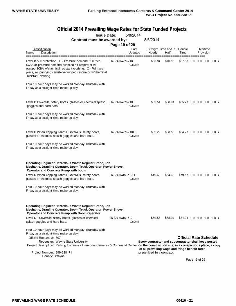
WAYNE STATE UNIVERSITY Parking Entrance Intercoms/ Cameras & Command Center 2014 WSU Project No. 999-238171
PREVAILING WAGE RATE SCHEDULE 00410 - 21
Official 2014 Prevailing Wage Rates for State Funded Projects Issue Date: 5/8/2014 Contract must be awarded by: 8/6/2014 Page 19 of 29 Classification Last Straight Time and a Double Overtime Name Description Updated Hourly Half Time Provision =================================================================================================== Level B & C protection. B - Pressure demand, full face EN-324-HW220-Z1B $53.84 $70.86 $87.87 H H H H H H H D Y SCBA or pressure demand supplied air respirator w/ 1/20/2012 escape SCBA w/chemical resistant clothing. C - Full face piece, air purifying canister-equipped respirator w/chemical resistant clothing. Four 10 hour days may be worked Monday-Thursday with Friday as a straight-time make up day.
Level D Coveralls, safety boots, glasses or chemical splash EN-324-HW220-Z1D $52.54 $68.91 $85.27 H H H H H H H D Y goggles and hard hats. 1/20/2012 Four 10 hour days may be worked Monday-Thursday with Friday as a straight-time make up day.
Level D When Capping Landfill Coveralls, safety boots, EN-324-HW220-Z1DCL $52.29 $68.53 $84.77 H H H H H H H D Y glasses or chemical splash goggles and hard hats. 1/20/2012 Four 10 hour days may be worked Monday-Thursday with Friday as a straight-time make up day.
Operating Engineer Hazardous Waste Regular Crane, Job Mechanic, Dragline Operator, Boom Truck Operator, Power Shovel Operator and Concrete Pump with boom Level D When Capping Landfill Coveralls, safety boots, EN-324-HWRC-Z1DCL $49.69 $64.63 $79.57 H H H H H H H D Y glasses or chemical splash goggles and hard hats. 1/20/2012 Four 10 hour days may be worked Monday-Thursday with Friday as a straight-time make up day.
Operating Engineer Hazardous Waste Regular Crane, Job Mechanic, Dragline Operator, Boom Truck Operator, Power Shovel Operator and Concrete Pump with Boom Operator Level D - Coveralls, safety boots, glasses or chemical EN-324-HWRC-Z1D $50.56 $65.94 $81.31 H H H H H H H D Y splash goggles and hard hats. 1/20/2012 Four 10 hour days may be worked Monday-Thursday with Friday as a straight-time make up day. Official Request #: 807 Official Rate Schedule Requestor: Wayne State University Every contractor and subcontractor shall keep posted Project Description: Parking Entrance - Intercoms/Cameras & Command Center on the construction site, in a conspicuous place, a copy of all prevailing wage and fringe benefit rates Project Number: 999-238171 prescribed in a contract. County: Wayne Page 19 of 29

WAYNE STATE UNIVERSITY Parking Entrance Intercoms/ Cameras & Command Center 2014 WSU Project No. 999-238171
PREVAILING WAGE RATE SCHEDULE 00410 - 22
Official 2014 Prevailing Wage Rates for State Funded Projects Issue Date: 5/8/2014 Contract must be awarded by: 8/6/2014 Page 20 of 29 Classification Last Straight Time and a Double Overtime Name Description Updated Hourly Half Time Provision ===================================================================================================
Operating Engineer Hazardous Waste Regular Crane, Job Mechanic, Dragline Operator, Boom Truck Operator, Power Shovel Operator and Concrete Pump with booms Level B & C protection. B - Pressure demand, full face EN-324-HWRC-Z1B $51.86 $67.89 $83.91 H H H H H H H D Y SCBA or pressure demand supplied air respirator w/ 1/20/2012 escape SCBA w/chemical resistant clothing. C - Full face piece, air purifying canister-equipped respirator w/chemical resistant clothing. Four 10 hour days may be worked Monday-Thursday with Friday as a straight-time make up day.
Operating Engineer Hazardous Waste Regular Crane, Job Mechanic, Dragline Operator, Boom Truck Operator, Power Shovel Operators and Concrete Pump with booms Level A - Fully encapsulating chemical resistant suit w/ EN-324-HWRC-Z1A $52.81 $69.31 $85.81 H H H H H H H D Y pressure demand, full face piece SCBA or pressure demand 1/20/2012 supplied air respirator w/ escape SCBA. The highest available level of respiratory, skin and eye protection. Four 10 hour days may be worked Monday-Thursday with Friday as a straight-time make up day.
Operating Engineer Steel Work Forklift, 1 Drum Hoist EN-324-ef $57.11 $75.12 $93.13 H H D H H H D D Y 6/17/2013
Crane w/ 120' boom or longer EN-324-SW120 $59.81 $79.17 $98.53 H H D H H H D D Y 6/14/2013
Crane w/ 120' boom or longer w/ Oiler EN-324-SW120-O $60.81 $80.67 $100.53 H H D H H H D D Y 6/14/2013
Crane w/ 140' boom or longer EN-324-SW140 $60.99 $80.94 $100.89 H H D H H H D D Y 6/14/2013
Crane w/ 140' boom or longer W/ Oiler EN-324-SW140-O $61.99 $82.44 $102.89 H H D H H H D D Y 6/14/2013
Boom & Jib 220' or longer EN-324-SW220 $61.26 $81.35 $101.43 H H D H H H D D Y 6/14/2013 Crane w/ 220' boom or longer w/ Oiler EN-324-SW220-O $62.26 $82.85 $103.43 H H D H H H D D Y 6/14/2013 Official Request #: 807 Official Rate Schedule Requestor: Wayne State University Every contractor and subcontractor shall keep posted Project Description: Parking Entrance - Intercoms/Cameras & Command Center on the construction site, in a conspicuous place, a copy of all prevailing wage and fringe benefit rates Project Number: 999-238171 prescribed in a contract. County: Wayne Page 20 of 29

WAYNE STATE UNIVERSITY Parking Entrance Intercoms/ Cameras & Command Center 2014 WSU Project No. 999-238171
PREVAILING WAGE RATE SCHEDULE 00410 - 23
Official 2014 Prevailing Wage Rates for State Funded Projects Issue Date: 5/8/2014 Contract must be awarded by: 8/6/2014 Page 21 of 29 Classification Last Straight Time and a Double Overtime Name Description Updated Hourly Half Time Provision =================================================================================================== Boom & Jib 300' or longer EN-324-SW300 $62.76 $83.60 $104.43 H H D H H H D D Y 6/14/2013
Crane w/ 300' boom or longer w/ Oiler EN-324-SW300-O $63.76 $85.10 $106.43 H H D H H H D D Y 6/14/2013
Boom & Jib 400' or longer EN-324-SW400 $64.26 $85.85 $107.43 H H D H H H D D Y 6/14/2013
Crane w/ 400' boom or longer w/ Oiler EN-324-SW400-O $65.26 $87.35 $109.43 H H D H H H D D Y 6/14/2013
Crane Operator, Job Mechanic, 3 Drum Hoist & Excavator EN-324-SWCO $59.45 $78.63 $97.81 H H D H H H D D Y 6/17/2013 Apprentice Rates: 0-999 hours $47.09 $60.51 $73.94 1,000-1,999 hours $49.01 $63.40 $77.78 2,000-2,999 hours $50.93 $66.28 $81.62 3,000-3,999 hours $52.85 $69.16 $85.46 4,000-4,999 hours $54.76 $72.02 $89.28 5,000 hours $56.68 $74.91 $93.12
Crane w/ Oiler EN-324-SWCO-O $60.45 $80.13 $99.81 H H D H H H D D Y 6/17/2013
Compressor or Welder Operator EN-324-SWCW $52.00 $67.46 $82.91 H H D H H H D D Y 6/17/2013
Hoisting Operator, 2 Drum Hoist, & Rubber Tire Backhoe EN-324-SWHO $58.81 $77.67 $96.53 H H D H H H D D Y 6/17/2013
Oiler EN-324-SWO $50.59 $65.34 $80.09 H H D H H H D D Y 6/17/2013
Tower Crane & Derrick where work is 50' or more above EN-324-SWTD50 $60.54 $80.27 $99.99 H H D H H H D D Y first level 6/14/2013
Tower Crane & Derrick 50' or more w/ Oiler where work EN-324-SWTD50-O $61.54 $81.77 $101.99 H H D H H H D D Y station is 50' or more above first level 6/14/2013
Official Request #: 807 Official Rate Schedule Requestor: Wayne State University Every contractor and subcontractor shall keep posted Project Description: Parking Entrance - Intercoms/Cameras & Command Center on the construction site, in a conspicuous place, a copy of all prevailing wage and fringe benefit rates Project Number: 999-238171 prescribed in a contract. County: Wayne Page 21 of 29

WAYNE STATE UNIVERSITY Parking Entrance Intercoms/ Cameras & Command Center 2014 WSU Project No. 999-238171
PREVAILING WAGE RATE SCHEDULE 00410 - 24
Official 2014 Prevailing Wage Rates for State Funded Projects Issue Date: 5/8/2014 Contract must be awarded by: 8/6/2014 Page 22 of 29 Classification Last Straight Time and a Double Overtime Name Description Updated Hourly Half Time Provision ===================================================================================================
Operating Engineer Underground Class I Equipment EN-324A1-UC1 $50.34 $65.33 $80.32 H H H H H H H D Y 9/13/2013 Apprentice Rates: 0-999 hours $40.75 $51.25 $61.74 1,000-1,999 hours $42.24 $53.48 $64.72 2,000-2,999 hours $43.75 $55.75 $67.74 3,000-3,999 hours $45.24 $57.98 $70.72 4,000-4,999 hours $46.74 $60.23 $73.72 5,000-5,999 hours $48.25 $62.50 $76.74
Class II Equipment EN-324A1-UC2 $45.61 $58.24 $70.86 H H H H H H H D Y 9/13/2013
Class III Equipment EN-324A1-UC3 $44.88 $57.14 $69.40 H H H H H H H D Y 9/13/2013
Class IV Equipment EN-324A1-UC4 $44.31 $56.29 $68.26 H H H H H H H D Y 9/13/2013
Master Mechanic EN-324A1-UMM $50.59 $65.71 $80.82 H H H H H H H D Y 9/13/2013
Painter Painter (8 hours of repaint work performed on Sunday shall PT-22-P $41.32 $53.78 $66.23 H H D H D D D D Y be paid time & one half rate) 6/18/2012 Four 10s allowed Monday-Thursday with Friday makeup day if job down due to weather, holiday or other conditions beyond the control of the employer.
Apprentice Rates: First 6 months $28.87 $35.10 $41.33 Second 6 months $32.60 $40.69 $48.79 Third 6 months $33.85 $42.57 $51.29 Fourth 6 months $35.09 $44.43 $53.77 Fifth 6 months $36.34 $46.31 $56.27 Final 6 months $37.58 $48.17 $58.75
Pipe and Manhole Rehab General Laborer for rehab work or normal cleaning and TM247 $27.20 $36.70 H H H H H H H H N cctv work-top man, scaffold man, CCTV assistant, jetter- 10/15/2012 vac assistant
Official Request #: 807 Official Rate Schedule Requestor: Wayne State University Every contractor and subcontractor shall keep posted Project Description: Parking Entrance - Intercoms/Cameras & Command Center on the construction site, in a conspicuous place, a copy of all prevailing wage and fringe benefit rates Project Number: 999-238171 prescribed in a contract. County: Statewide Page 22 of 29

WAYNE STATE UNIVERSITY Parking Entrance Intercoms/ Cameras & Command Center 2014 WSU Project No. 999-238171
PREVAILING WAGE RATE SCHEDULE 00410 - 25
Official 2014 Prevailing Wage Rates for State Funded Projects Issue Date: 5/8/2014 Contract must be awarded by: 8/6/2014 Page 23 of 29 Classification Last Straight Time and a Double Overtime Name Description Updated Hourly Half Time Provision =================================================================================================== Tap cutter/CCTV Tech/Grout Equipment Operator: unit TM247-2 $31.70 $43.45 H H H H H H H H N driver and operator of CCTV; grouting equipment and tap 10/15/2012 cutting equipment
CCTV Technician/Combo Unit Operator: unit driver and TM247-3 $30.45 $41.57 H H H H H H H H N operator of cctv unit or combo unit in connection with 10/15/2012 normal cleaning and televising work
Boiler Operator: unit driver and operator of steam/water TM247-4 $32.20 $44.20 H H H H H H H H N heater units and all ancillary equipment associated 10/15/2012
Combo Unit driver & Jetter-Vac Operator TM247-5 $32.20 $44.20 H H H H H H H H N 10/15/2012
Pipe Bursting & Slip-lining Equipment Operator TM247-6 $33.20 $45.70 H H H H H H H H N 10/15/2012
Pipefitter Pipefitter PF-636 $65.63 $86.83 $104.03 H H D H D D D D Y 6/26/2013 Apprentice Rates: 1st & 2nd periods $26.93 $35.28 $42.28 3rd period $28.93 $38.28 $46.28 4th period $30.18 $40.16 $48.78 5th period $31.43 $42.03 $51.28 6th period $32.68 $43.90 $53.78 7th period $33.93 $45.78 $56.28 8th period $34.93 $47.28 $58.28 9th period $35.93 $48.78 $60.28 10th period $37.36 $50.92 $63.14
Plasterer Plasterer BR1P $45.04 $67.56 $90.08 H H H H H H H D N 11/1/2012 Apprentice Rates: 1st 6 months $32.11 $48.17 $64.22 2nd 6 months $33.40 $50.10 $66.80 3rd 6 months $34.69 $52.04 $69.38 4th 6 months $37.28 $55.92 $74.56 5th 6 months $39.87 $59.81 $79.74 6th 6 months $42.45 $63.68 $84.90
Official Request #: 807 Official Rate Schedule Requestor: Wayne State University Every contractor and subcontractor shall keep posted Project Description: Parking Entrance - Intercoms/Cameras & Command Center on the construction site, in a conspicuous place, a copy of all prevailing wage and fringe benefit rates Project Number: 999-238171 prescribed in a contract. County: Wayne Page 23 of 29
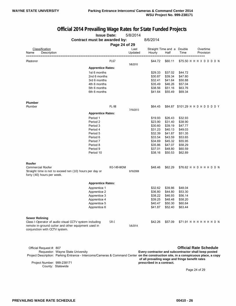
WAYNE STATE UNIVERSITY Parking Entrance Intercoms/ Cameras & Command Center 2014 WSU Project No. 999-238171
PREVAILING WAGE RATE SCHEDULE 00410 - 26
Official 2014 Prevailing Wage Rates for State Funded Projects Issue Date: 5/8/2014 Contract must be awarded by: 8/6/2014 Page 24 of 29 Classification Last Straight Time and a Double Overtime Name Description Updated Hourly Half Time Provision =================================================================================================== Plasterer PL67 $44.72 $60.11 $75.50 H H H X D D D D N 9/8/2010 Apprentice Rates: 1st 6 months $29.33 $37.02 $44.72 2nd 6 months $30.87 $39.34 $47.80 3rd 6 months $32.41 $41.64 $50.88 4th 6 months $35.49 $46.26 $57.04 5th 6 months $38.56 $51.16 $63.76 6th 6 months $41.64 $55.49 $69.34
Plumber Plumber PL-98 $64.45 $84.87 $101.29 H H D H D D D D Y 7/18/2013 Apprentice Rates: Period 1 $19.93 $26.43 $32.93 Period 2 $23.90 $31.40 $38.90 Period 3 $30.60 $39.19 $47.77 Period 4 $31.23 $40.13 $49.03 Period 5 $32.39 $41.87 $51.35 Period 6 $33.54 $43.59 $53.65 Period 7 $34.69 $45.32 $55.95 Period 8 $35.86 $47.07 $58.29 Period 9 $37.01 $48.80 $60.59 Period 10 $38.16 $50.53 $62.89
Roofer Commercial Roofer RO-149-WOM $48.46 $62.29 $76.62 H H D H H H D D N Straight time is not to exceed ten (10) hours per day or 8/18/2008 forty (40) hours per week.
Apprentice Rates: Apprentice 1 $32.62 $39.86 $48.04 Apprentice 2 $36.80 $44.80 $53.30 Apprentice 3 $38.22 $46.93 $56.14 Apprentice 4 $39.25 $48.48 $58.20 Apprentice 5 $40.47 $50.30 $60.64 Apprentice 6 $41.87 $52.40 $63.44
Sewer Relining Class I-Operator of audio visual CCTV system including SR-I $42.26 $57.09 $71.91 H H H H H H H D N remote in-ground cutter and other equipment used in 5/6/2014 conjunction with CCTV system.
Official Request #: 807 Official Rate Schedule Requestor: Wayne State University Every contractor and subcontractor shall keep posted Project Description: Parking Entrance - Intercoms/Cameras & Command Center on the construction site, in a conspicuous place, a copy of all prevailing wage and fringe benefit rates Project Number: 999-238171 prescribed in a contract. County: Statewide Page 24 of 29

WAYNE STATE UNIVERSITY Parking Entrance Intercoms/ Cameras & Command Center 2014 WSU Project No. 999-238171
PREVAILING WAGE RATE SCHEDULE 00410 - 27
Official 2014 Prevailing Wage Rates for State Funded Projects Issue Date: 5/8/2014 Contract must be awarded by: 8/6/2014 Page 25 of 29 Classification Last Straight Time and a Double Overtime Name Description Updated Hourly Half Time Provision =================================================================================================== Class II-Operator of hot water heaters and circulation SR-II $40.73 $54.79 $68.85 H H H H H H H D N system; water jetters; and vacuum and mechanical debris 5/6/2014 removal systems and those assisting.
Sheet Metal Worker Sheet Metal Worker SHM-80 $60.77 $77.68 $94.59 H H D X H H H D Y A 4 10 schedule may be worked, 4 consecutive days 8/1/2013 Monday thru Friday.
Apprentice Rates: 1st & 2nd Periods Indentured after 6-1- $38.12 $45.73 $53.34 11 3rd & 4th Periods Indentured after 6-1- $39.82 $48.28 $56.74 11 5th & 6th Periods Indentured after 6-1- $41.50 $50.80 $60.10 11 7th & 8th Periods Indentured after 6-1- $43.19 $53.34 $63.48 11 9th & 10th Periods Indentured before 6- $50.86 $63.38 $75.90 1-11
Siding and decking SHM-80-SD $42.07 $54.28 $66.48 H H H H H H H D Y 1/13/2014
Sprinkler Fitter Sprinkler Fitter SP 704 $63.92 $84.88 $105.83 H H D H D D D D Y 4 ten hour days allowed Monday-Friday 1/10/2014 Double time pay due after 12 hours worked M-F
Apprentice Rates: 1st Period $27.77 $36.15 $44.53 2nd Period $40.87 $50.30 $59.73 3rd Period $42.97 $53.45 $63.93 4th Period $45.06 $56.59 $68.11 5th Period $47.16 $59.73 $72.31 6th Period $49.25 $62.87 $76.49 7th Period $51.35 $66.02 $80.69 8th Period $53.44 $69.15 $84.87 9th Period $55.54 $72.31 $89.07 10th Period $57.63 $75.44 $93.25
Official Request #: 807 Official Rate Schedule Requestor: Wayne State University Every contractor and subcontractor shall keep posted Project Description: Parking Entrance - Intercoms/Cameras & Command Center on the construction site, in a conspicuous place, a copy of all prevailing wage and fringe benefit rates Project Number: 999-238171 prescribed in a contract. County: Wayne Page 25 of 29

WAYNE STATE UNIVERSITY Parking Entrance Intercoms/ Cameras & Command Center 2014 WSU Project No. 999-238171
PREVAILING WAGE RATE SCHEDULE 00410 - 28
Official 2014 Prevailing Wage Rates for State Funded Projects Issue Date: 5/8/2014 Contract must be awarded by: 8/6/2014 Page 26 of 29 Classification Last Straight Time and a Double Overtime Name Description Updated Hourly Half Time Provision ===================================================================================================
Terrazzo Terrazzo Finisher BR1-TRF $43.43 $54.38 $65.33 H H D H D D D D Y A 4 ten workweek may be worked Monday thru Thursday 9/5/2013 or Tuesday thru Friday.
Apprentice Rates: Level 1 $18.80 $24.77 $30.73 Level 2 $19.99 $26.55 $33.11 Level 3 $26.67 $33.52 $40.36 Level 4 $28.12 $35.69 $43.26 Level 5 $29.62 $37.37 $45.13 Level 6 $31.22 $39.37 $47.51 Level 7 $32.89 $41.08 $49.26 Level 8 $34.36 $42.95 $51.54
Terrazzo Worker BR1-TRW $49.11 $62.90 $76.69 H H D H D D D D Y A 4 ten workweek may be worked Monday thru Thursday 9/5/2013 or Tuesday thru Friday.
Apprentice Rates: Level 1 $24.83 $32.24 $39.65 Level 2 $27.85 $36.04 $44.23 Level 3 $33.00 $41.45 $49.90 Level 4 $35.70 $45.09 $54.49 Level 5 $37.94 $47.57 $57.21 Level 6 $41.55 $52.91 $64.27 Level 7 $42.21 $53.72 $65.22 Level 8 $43.13 $55.10 $67.06
Tile Tile Finisher BR1-TF $42.96 $53.68 $64.39 H H D H D D D D Y A 4 ten workweek may be worked Monday thru Thursday 9/5/2013 or Tuesday thru Friday.
Apprentice Rates: Level 1 $18.80 $24.77 $30.73 Level 2 $19.99 $26.55 $33.11 Level 3 $26.67 $33.52 $40.36 Level 4 $28.12 $35.69 $43.26 Level 5 $29.62 $37.37 $45.13 Level 6 $31.22 $39.37 $47.51 Level 7 $32.89 $41.08 $49.26 Level 8 $34.36 $42.95 $51.54
Official Request #: 807 Official Rate Schedule Requestor: Wayne State University Every contractor and subcontractor shall keep posted Project Description: Parking Entrance - Intercoms/Cameras & Command Center on the construction site, in a conspicuous place, a copy of all prevailing wage and fringe benefit rates Project Number: 999-238171 prescribed in a contract. County: Wayne Page 26 of 29
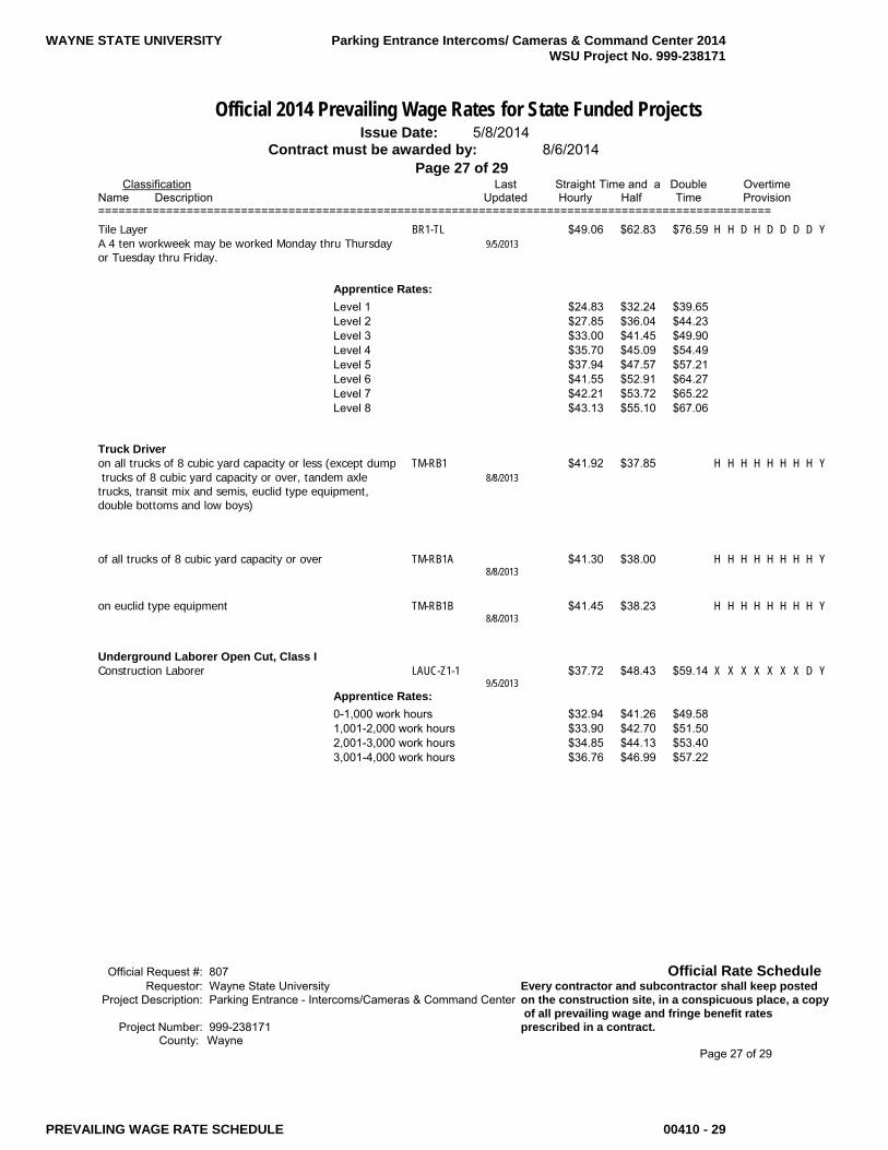
WAYNE STATE UNIVERSITY Parking Entrance Intercoms/ Cameras & Command Center 2014 WSU Project No. 999-238171
PREVAILING WAGE RATE SCHEDULE 00410 - 29
Official 2014 Prevailing Wage Rates for State Funded Projects Issue Date: 5/8/2014 Contract must be awarded by: 8/6/2014 Page 27 of 29 Classification Last Straight Time and a Double Overtime Name Description Updated Hourly Half Time Provision =================================================================================================== Tile Layer BR1-TL $49.06 $62.83 $76.59 H H D H D D D D Y A 4 ten workweek may be worked Monday thru Thursday 9/5/2013 or Tuesday thru Friday.
Apprentice Rates: Level 1 $24.83 $32.24 $39.65 Level 2 $27.85 $36.04 $44.23 Level 3 $33.00 $41.45 $49.90 Level 4 $35.70 $45.09 $54.49 Level 5 $37.94 $47.57 $57.21 Level 6 $41.55 $52.91 $64.27 Level 7 $42.21 $53.72 $65.22 Level 8 $43.13 $55.10 $67.06
Truck Driver on all trucks of 8 cubic yard capacity or less (except dump TM-RB1 $41.92 $37.85 H H H H H H H H Y trucks of 8 cubic yard capacity or over, tandem axle 8/8/2013 trucks, transit mix and semis, euclid type equipment, double bottoms and low boys)
of all trucks of 8 cubic yard capacity or over TM-RB1A $41.30 $38.00 H H H H H H H H Y 8/8/2013
on euclid type equipment TM-RB1B $41.45 $38.23 H H H H H H H H Y 8/8/2013
Underground Laborer Open Cut, Class I Construction Laborer LAUC-Z1-1 $37.72 $48.43 $59.14 X X X X X X X D Y 9/5/2013 Apprentice Rates: 0-1,000 work hours $32.94 $41.26 $49.58 1,001-2,000 work hours $33.90 $42.70 $51.50 2,001-3,000 work hours $34.85 $44.13 $53.40 3,001-4,000 work hours $36.76 $46.99 $57.22
Official Request #: 807 Official Rate Schedule Requestor: Wayne State University Every contractor and subcontractor shall keep posted Project Description: Parking Entrance - Intercoms/Cameras & Command Center on the construction site, in a conspicuous place, a copy of all prevailing wage and fringe benefit rates Project Number: 999-238171 prescribed in a contract. County: Wayne Page 27 of 29

WAYNE STATE UNIVERSITY Parking Entrance Intercoms/ Cameras & Command Center 2014 WSU Project No. 999-238171
PREVAILING WAGE RATE SCHEDULE 00410 - 30
Official 2014 Prevailing Wage Rates for State Funded Projects Issue Date: 5/8/2014 Contract must be awarded by: 8/6/2014 Page 28 of 29 Classification Last Straight Time and a Double Overtime Name Description Updated Hourly Half Time Provision ===================================================================================================
Underground Laborer Open Cut, Class II Mortar and material mixer, concrete form man, signal LAUC-Z1-2 $37.83 $48.60 $59.36 X X X X X X X D Y man, well point man, manhole, headwall and catch basin 10/25/2013 builder, guard rail builders, headwall, seawall, breakwall, dock builder and fence erector.
Apprentice Rates: 0-1,000 work hours $33.02 $41.38 $49.74 1,001-2,000 work hours $33.98 $42.82 $51.66 2,001-3,000 work hours $34.95 $44.27 $53.60 3,001-4,000 work hours $36.87 $47.15 $57.44
Underground Laborer Open Cut, Class III Air, gasoline and electric tool operator, vibrator operator, LAUC-Z1-3 $37.88 $48.67 $59.46 X X X X X X X D Y drillers, pump man, tar kettle operator, bracers, rodder, 9/5/2013 reinforced steel or mesh man (e.g. wire mesh, steel mats, dowel bars, etc.), cement finisher, welder, pipe jacking and boring man, wagon drill and air track operator and concrete saw operator (under 40 h.p.), windlass and tugger man, and directional boring man.
Apprentice Rates: 0-1,000 work hours $33.06 $41.44 $49.82 1,001-2,000 work hours $34.02 $42.88 $51.74 2,001-3,000 work hours $34.99 $44.33 $53.68 3,001-4,000 work hours $36.92 $47.23 $57.54
Underground Laborer Open Cut, Class IV Trench or excavating grade man. LAUC-Z1-4 $37.96 $48.79 $59.62 X X X X X X X D Y 9/5/2013 Apprentice Rates: 0-1,000 work hours $33.12 $41.53 $49.94 1,001-2,000 work hours $34.09 $42.99 $51.88 2,001-3,000 work hours $35.06 $44.44 $53.82 3,001-4,000 work hours $36.99 $47.33 $57.68
Underground Laborer Open Cut, Class V Pipe Layer LAUC-Z1-5 $38.02 $48.88 $59.74 X X X X X X X D Y 9/5/2013 Apprentice Rates: 0-1,000 work hours $33.16 $41.59 $50.02 1,001-2,000 work hours $34.14 $43.06 $51.98 2,001-3,000 work hours $35.11 $44.51 $53.92 3,001-4,000 work hours $37.05 $47.43 $57.80
Official Request #: 807 Official Rate Schedule Requestor: Wayne State University Every contractor and subcontractor shall keep posted Project Description: Parking Entrance - Intercoms/Cameras & Command Center on the construction site, in a conspicuous place, a copy of all prevailing wage and fringe benefit rates Project Number: 999-238171 prescribed in a contract. County: Wayne Page 28 of 29

WAYNE STATE UNIVERSITY Parking Entrance Intercoms/ Cameras & Command Center 2014 WSU Project No. 999-238171
PREVAILING WAGE RATE SCHEDULE 00410 - 31
Official 2014 Prevailing Wage Rates for State Funded Projects Issue Date: 5/8/2014 Contract must be awarded by: 8/6/2014 Page 29 of 29 Classification Last Straight Time and a Double Overtime Name Description Updated Hourly Half Time Provision ===================================================================================================
Underground Laborer Open Cut, Class VI Grouting man, top man assistant, audio visual television LAUC-Z1-6 $35.47 $45.06 $54.64 X X X X X X X D Y operations and all other operations in connection with 9/5/2013 closed circuit television inspection, pipe cleaning and pipe relining work and the installation and repair of water service pipe and appurtenances.
Apprentice Rates: 0-1,000 work hours $31.25 $38.73 $46.20 1,001-2,000 work hours $32.10 $40.00 $47.90 2,001-3,000 work hours $32.94 $41.26 $49.58 3,001-4,000 work hours $34.63 $43.79 $52.96
Underground Laborer Open Cut, Class VII Restoration laborer, seeding, sodding, planting, cutting, LAUC-Z1-7 $32.09 $39.99 $47.88 X X X X X X X D Y mulching and topsoil grading and the restoration of 9/5/2013 property such as replacing mail boxes, wood chips, planter boxes, flagstones etc.
Apprentice Rates: 0-1,000 work hours $28.72 $34.93 $41.14 1,001-2,000 work hours $29.39 $35.93 $42.48 2,001-3,000 work hours $30.07 $36.95 $43.84 3,001-4,000 work hours $31.42 $38.98 $46.54
Official Request #: 807 Official Rate Schedule Requestor: Wayne State University Every contractor and subcontractor shall keep posted Project Description: Parking Entrance - Intercoms/Cameras & Command Center on the construction site, in a conspicuous place, a copy of all prevailing wage and fringe benefit rates Project Number: 999-238171 prescribed in a contract. County: Wayne Page 29 of 29
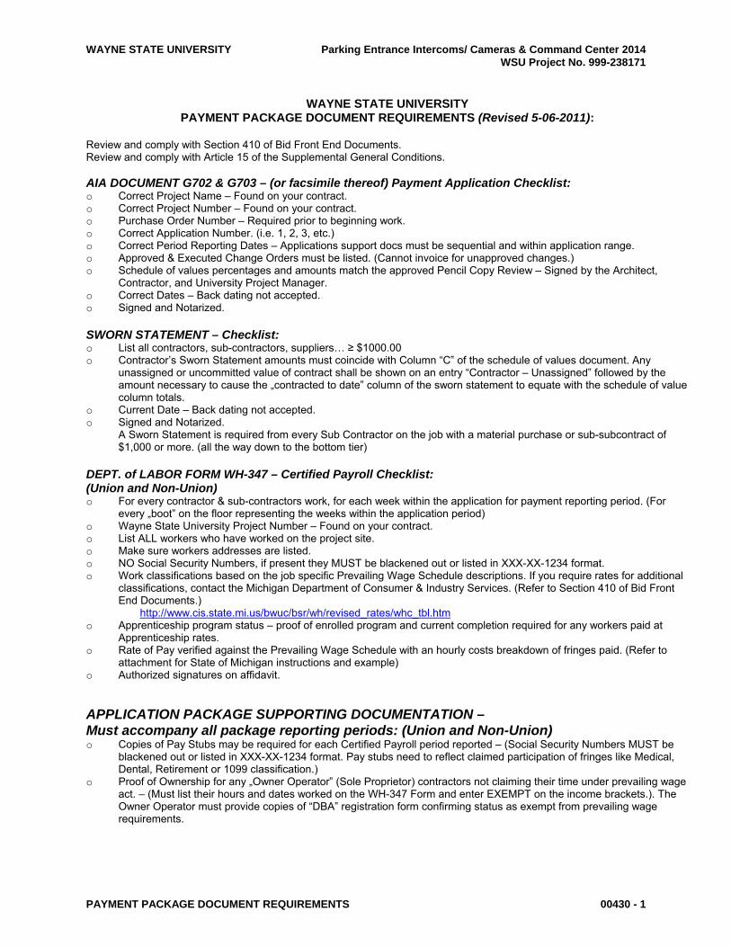
WAYNE STATE UNIVERSITY Parking Entrance Intercoms/ Cameras & Command Center 2014 WSU Project No. 999-238171
PAYMENT PACKAGE DOCUMENT REQUIREMENTS 00430 - 1
WAYNE STATE UNIVERSITY PAYMENT PACKAGE DOCUMENT REQUIREMENTS (Revised 5-06-2011):
Review and comply with Section 410 of Bid Front End Documents. Review and comply with Article 15 of the Supplemental General Conditions. AIA DOCUMENT G702 & G703 – (or facsimile thereof) Payment Application Checklist: o Correct Project Name – Found on your contract. o Correct Project Number – Found on your contract. o Purchase Order Number – Required prior to beginning work. o Correct Application Number. (i.e. 1, 2, 3, etc.) o Correct Period Reporting Dates – Applications support docs must be sequential and within application range. o Approved & Executed Change Orders must be listed. (Cannot invoice for unapproved changes.) o Schedule of values percentages and amounts match the approved Pencil Copy Review – Signed by the Architect,
Contractor, and University Project Manager. o Correct Dates – Back dating not accepted. o Signed and Notarized. SWORN STATEMENT – Checklist: o List all contractors, sub-contractors, suppliers… ≥ $1000.00 o Contractor’s Sworn Statement amounts must coincide with Column “C‟ of the schedule of values document. Any
unassigned or uncommitted value of contract shall be shown on an entry “Contractor – Unassigned‟ followed by the amount necessary to cause the „contracted to date‟ column of the sworn statement to equate with the schedule of value column totals.
o Current Date – Back dating not accepted. o Signed and Notarized. A Sworn Statement is required from every Sub Contractor on the job with a material purchase or sub-subcontract of
$1,000 or more. (all the way down to the bottom tier) DEPT. of LABOR FORM WH-347 – Certified Payroll Checklist: (Union and Non-Union) o For every contractor & sub-contractors work, for each week within the application for payment reporting period. (For
every „boot‟ on the floor representing the weeks within the application period) o Wayne State University Project Number – Found on your contract. o List ALL workers who have worked on the project site. o Make sure workers addresses are listed. o NO Social Security Numbers, if present they MUST be blackened out or listed in XXX-XX-1234 format. o Work classifications based on the job specific Prevailing Wage Schedule descriptions. If you require rates for additional
classifications, contact the Michigan Department of Consumer & Industry Services. (Refer to Section 410 of Bid Front End Documents.)
http://www.cis.state.mi.us/bwuc/bsr/wh/revised_rates/whc_tbl.htm o Apprenticeship program status – proof of enrolled program and current completion required for any workers paid at
Apprenticeship rates. o Rate of Pay verified against the Prevailing Wage Schedule with an hourly costs breakdown of fringes paid. (Refer to
attachment for State of Michigan instructions and example) o Authorized signatures on affidavit.
APPLICATION PACKAGE SUPPORTING DOCUMENTATION – Must accompany all package reporting periods: (Union and Non-Union) o Copies of Pay Stubs may be required for each Certified Payroll period reported – (Social Security Numbers MUST be
blackened out or listed in XXX-XX-1234 format. Pay stubs need to reflect claimed participation of fringes like Medical, Dental, Retirement or 1099 classification.)
o Proof of Ownership for any „Owner Operator‟ (Sole Proprietor) contractors not claiming their time under prevailing wage act. – (Must list their hours and dates worked on the WH-347 Form and enter EXEMPT on the income brackets.). The Owner Operator must provide copies of “DBA” registration form confirming status as exempt from prevailing wage requirements.

WAYNE STATE UNIVERSITY Parking Entrance Intercoms/ Cameras & Command Center 2014 WSU Project No. 999-238171
PAYMENT PACKAGE DOCUMENT REQUIREMENTS 00430 - 2
o Proof of Stored Materials – (Detailed Bill of Sale, certificate of insurance or endorsement page specifically insuring the stored materials, pictures, when large value. WSU reserves the right to on site verification of material. Stored material must be separated from ordinary inventory and labeled for WSU project.
o Partial Unconditional Waivers – Must release the accumulated amount paid for work and be immediately provided, or provided with the subsequent application for payment. Waivers shall be provided for contractors, sub-contractors, and suppliers listed on the Sworn Statements. (This is required at all tiers)
o Full Unconditional Waivers – Prime Contractor must deliver fully executed Full Unconditional Waiver upon receipt of final payment. Full Unconditional waivers may be required of sub-contractors and suppliers in advance of final Contractor payment on bonded projects This requirement shall be determined on a project-by-project basis. Full Unconditional waivers shall be required in advance of or at the time of final payment on all non-bonded projects from all subcontractors and suppliers listed on Sworn Statements, or who have provided a notice of furnishing.
o Partial Conditional Waivers – The Contractor shall provide a Partial Conditional Waivers covering the entire amount of the application for payment. For non-bonded Projects – A partial conditional waiver from all subcontractors must accompany any application for payment within which a subcontractor draw is included.
o Sworn Statements – Required for all Sub Contractors, and Sub-subcontractors (etc.) with any contracts or purchases exceeding $1,000.
FINAL PAYMENT EXCHANGE – Checklist: o Clear and concise As-Built drawings. o Operation and Maintenance Manuals. o Required training must be completed (if applicable). o Warranty of work in accordance with project documents. o Certificate of Substantial Completion. o Full Unconditional Waiver The Project Manager may provide additional requirements as may apply to individual jobs Revised 5-6-2011

WAYNE STATE UNIVERSITY Parking Entrance Intercoms/ Cameras & Command Center 2014 WSU Project No. 999-238171
AGREEMENT BETWEEN CONTRACTOR AND OWNER 00500 - 1 FOR CONSTRUCTION
AGREEMENT BETWEEN THE UNIVERSITY AND CONTRACTOR FOR CONSTRUCTION SERVICES (rev 6-2013)
Executed as of the ______ day of _________, 2014 by and between:
The Board of Governors, Wayne State University Detroit, Michigan 48202
(The University)
and
CONTRACTOR’S_NAME CONTRACTOR’S_ADDRESS
regarding
Parking Entrance Intercoms/ Cameras & Command Center 2014 71 West Forest
WSU Project No. 999-238171
WAYNE STATE UNIVERSITY Parking Entrance Intercoms/ Cameras & Command Center 2014 WSU Project No. 999-238171
AGREEMENT BETWEEN CONTRACTOR AND OWNER 00500 - 2 FOR CONSTRUCTION
In consideration of the mutual covenants and conditions contained herein, the Parties agree as follows:
Article 1 - Scope of Work
1.1 This Agreement provides for project includes an addition and expansion of the current parking office in Parking Structure 8. Office expansion is necessary to facilitate on-going work for the new Command Center scheduled to replace the conference room inside of the current office suite. , located at 71 West Forest. The documents listed in Article 4 fully define the scope of work.
1.2 The Contractor shall furnish all the labor, materials, equipment, services, and supervision to perform all the
work shown on the drawings and specifications listed in Article 18, including any addenda issued during the bid phase, and approved change orders issued during the construction phase.
1.3 The Contractor shall notify the University in writing within five (5) calendar days when the Contractor
discovers any condition that will affect the contract amount or the completion date.
Article 2 - Time of Completion
2.1 The work to be performed under this Agreement shall commence upon the Contractor’s receipt of a fully-executed Agreement, and substantial completion shall be achieved by September 22, 2014.
Article 3 - The Contract Sum
3.1 The University shall pay the Contractor a "lump sum/not-to-exceed (pick one)" amount of $$$$$$$ ("Amount in words 00" /100 dollars) for the performance of all work associated with the Contractor’s Base Bid "and Alternates (List)".
3.2 The University may, at its sole discretion, during the life of the contract, award the following alternates at the
amounts indicated: "(If section 3.2 is not used, delete all text and enter_Deleted"
Description Amount
Alternate #1 Alternate #2 Alternate #3
3.3 In the event additional work becomes necessary, the following unit prices will apply: (If section 3.3 is not used, delete all text and enter_Deleted)
Work Item Unit Price 1. 2. 3.
Article 4 - The Contract Documents
4.1 The Contract Documents shall consist of this Agreement, the drawings and specifications as listed in Article
18, the General Conditions of the Contract for Construction as defined by AIA Document A201 1970 Edition, except as otherwise provided herein, and Wayne State University’s Supplementary General Conditions 1997 Edition.
4.2 For any inconsistencies found among or between these Contract Documents, the language contained in this
Agreement shall prevail over all other documents and the Supplementary General Conditions shall prevail over the General Conditions. In the event of a conflict between the Drawings and Specifications, the requirement for the higher quantity and/or higher quality shall prevail.
Article 5 – Examination of Premises
5.1 The Contractor acknowledges that the University provided the opportunity for a thorough examination of the

WAYNE STATE UNIVERSITY Parking Entrance Intercoms/ Cameras & Command Center 2014 WSU Project No. 999-238171
AGREEMENT BETWEEN CONTRACTOR AND OWNER 00500 - 3 FOR CONSTRUCTION
project site and its surroundings and that the Contractor knows of no conditions preventing accomplishment of the full scope of work within the time and for the amount specified in this Agreement.
5.2 The University will deny all claims for additional time and/or cost for conditions that could have been
reasonably discovered during such an examination.
Article 6 - The Architect/Engineer
6.1 The Architect/Engineer for this project is: "(List the Architect and Engineer separately if appropriate)"
Dokes Design + Architecture, LLC 6722 Whispering Woods Drive West Bloomfield, MI 48322 (Architect Phone No / Fax No)
6.2 The University will appoint a Project Manager who will be the University’s point of contact for all matters of contract administration including, but not limited to, interpretation of documents, defining the scope of work, approving work schedules, and approving contract payments.
Article 7 - Additional Work
7.1 The University reserves the right to let other Agreements in connection with this work. The Contractor will
afford other Contractors or the University’s own workforce reasonable opportunity for the delivery and storage of their material and for the performance of their work and shall properly connect and coordinate its work with theirs.
7.2 If any part of the Contractor’s work depends for proper execution or results upon the work of another
Contractor or the University’s own workforce, the Contractor shall inspect and promptly report to the University’s Project Manager any defects in such work that render it unsuitable for such proper execution and results. The Contractor’s failure to so inspect and report shall constitute an acceptance of the work of others as fit and proper for reception of the Contractor’s work and as a waiver of any claim or defense against the University or other contractor which relies in whole or in part upon the contention that such work was unsuitable for proper execution and resolution.
Article 8 – Dispute Resolution
8.1 Jurisdiction over all claims, disputes, and other matters in question arising out of or relating to this contract or
the breach thereof, shall rest in the Court of Claims of the State of Michigan. No provision of this agreement may be construed as Wayne State University’s consent to submit any claim, dispute or other matter in question for dispute resolution pursuant to any arbitration or mediation process, whether or not provisions for dispute resolution are included in a document which has been incorporated by reference into this agreement. Specifically, all references to Arbitration contained in the General Conditions are superceded by this Article.
8.2 In any claim or dispute by the Contractor against the University, which cannot be resolved by negotiation, the
Contractor shall submit the dispute in writing for an administrative decision by the University’s Vice President for Finance and Administration, within 30 days of the end of negotiations. Any decision of the Vice President shall be made within 45 days of receipt from the Contractor and is final unless it is challenged by the Contractor by filing a lawsuit in the Court of Claims of the State of Michigan within one year of the issuance of the decision. The Contractor agrees that appeal to the Vice President is a condition precedent to filing suit in the Michigan Court of Claims.
8.3 For purposes of this section, the “end of negotiations” shall be deemed to have occurred when:
8.3.1 Either party informs the other that pursuant to this section, negotiations are at an impasse; or
8.3.2 The Contractor submits the dispute in writing to the Vice President.

WAYNE STATE UNIVERSITY Parking Entrance Intercoms/ Cameras & Command Center 2014 WSU Project No. 999-238171
AGREEMENT BETWEEN CONTRACTOR AND OWNER 00500 - 4 FOR CONSTRUCTION
8.4 Unless otherwise agreed by the University in writing, and notwithstanding any other rights or obligations of either of the parties under any Contract Documents or Agreement, the Contractor shall continue with the performance of its services and duties during the pendency of any negotiations or proceedings to resolve any claim or dispute, and the University shall continue to make payments in accordance with the Contract Documents; however, the University shall not be required or obligated to make payments on or against any such claims or disputes during the pendency of any proceeding to resolve such claims or disputes.
Article 9 - Termination for Convenience
9.1 Upon thirty days written notice to the Contractor, the University may, without cause and without prejudice to
any other right or remedy of the University, elect to terminate the contract. In such case, the Contractor shall only be paid (without duplication of any items), using a Close out Change Order, for the following:
9.1.1 For completed and acceptable work executed in accordance with the Contract Documents prior to
the effective date of termination, including fair and reasonable sums for overhead and profit on such Work;
9.1.2 For expenses sustained prior to the effective date of termination in performing services and furnishing labor, materials, or equipment as required by the Contract Documents in connection with uncompleted work, including fair and reasonable sums for overhead and profit on such expenses.
9.2 The Contractor shall not be paid on account of loss of anticipated profits or revenue, delay or disruption, or
other economic loss arising out of or resulting from such termination. For purposes of this section, “fair and reasonable sums for overhead and profit” shall be determined by reference to Michigan law, without reference to principles used for such determinations in arbitration.
Article 10 - Progress Payments
10.1 On or before the 20th day of each month, the Contractor shall submit a written application for payment, using
form AIA G702, to the Architect/Engineer and the University’s Project Manager for review. The Architect/Engineer shall have ten (10) calendar days to accept or reject the Contractor’s application for payment. Acceptable applications for payment shall then be submitted to the University for Payment of authorized amount(s) within thirty (30) calendar days of receipt by the University’s Project Manager.
10.2 The application for payment shall contain a full schedule of values organized and sorted by subcontractor, by
Construction Specifications Institute standard work categories, or in another format acceptable to the University.
10.3 Monthly progress payments shall show the percentage of work installed as of the date of the application, less
amount previously installed and the amount due for the application period. The Contractor shall deduct a 10% retainage from the balance due for each progress payment and indicate the net amount due on each application.
10.4 When 50% of the work associated with this Agreement is installed, the Contractor shall not deduct additional
retainage from the balance due from the University. When substantial completion is achieved and acknowledged by the Architect/Engineer, the Contractor and the University in writing, the University shall remit to the Contractor all but 2% of the retainage. The remaining 2% shall be retained by the University until the final payment is authorized and remitted to the Contractor.
Article 11 - Acceptance and Final Payments
11.1 Final payment shall be due thirty (30) days after the completion of the work, including all punch list items,
provided the work is fully completed and the Agreement fully performed. 11.2 Upon receipt of written notice that the work is ready for final inspection and acceptance, the
Architect/Engineer shall promptly inspect the work. When the Architect/Engineer concludes that the work is acceptable and the Agreement to be fully performed, the Architect/Engineer shall promptly issue a final certificate with an original signature, stating that the work provided is complete and acceptable and that the entire remaining balance found to be due the Contractor shall be remitted by the University once the final

WAYNE STATE UNIVERSITY Parking Entrance Intercoms/ Cameras & Command Center 2014 WSU Project No. 999-238171
AGREEMENT BETWEEN CONTRACTOR AND OWNER 00500 - 5 FOR CONSTRUCTION
application for payment is received. 11.3 If, after the work has been substantially completed, full completion thereof is materially delayed through no
fault of the Contractor, and the Architect/Engineer so certifies, the University shall, upon certificate of the Architect/Engineer, and without terminating the Contract, make payments of the balance due for that portion of the work fully completed and accepted. Such payments shall be made under the terms and conditions governing final payment, except that it shall not constitute a waiver of claims.
Article 12 - Non-Discrimination
12.1 The Contractor agrees that it will not discriminate against any employee or applicant for employment, to be employed in the performance of this Agreement, with respect to hire, tenure, terms, conditions or privileges of employment or any matter directly or indirectly related to employment, because of race, color, religion, sex, age, national origin, or ancestry. Breach of this covenant may be regarded as material breach of this Agreement.
12.2 The Contractor further agrees that it will, in all subcontracts relating to the performance of the work under
this Agreement, provide in its subcontracts that the subcontractor will not discriminate against any employee or applicant for employment, to be employed in the performance of such contract, with respect to hire, tenure, terms, conditions or privileges of employment, or any matter directly or indirectly related to employment because of race, sex, age, color, religion, national origin or ancestry. Breach of this covenant may also be regarded as a material breach of this Agreement.
Article 13 – Laborers and Mechanics
13.1 All laborers and mechanics must be covered by Worker’s Compensation and Employer’s Liability Insurance
as required by Federal and Michigan law. The Contractor shall also require all of its Subcontractors to maintain this insurance coverage.
13.2 The Contractor acknowledges and shall abide by the University’s prohibition on use of 1099 independent
contractors and owner / operator business entities. The Contractor shall ensure that all classifications of laborers and construction mechanics performing Work on the Project job site are employees of the Contractor or any Trade Contractor for any tier thereof, and that each worker is covered by workers compensation insurance.
Article 14 - Prevailing Wages
14.1 The Contractor and each subcontractor shall pay to each class of mechanics and laborers not less than the wage and fringe benefit rates prevailing in the Detroit Metropolitan Area, as determined by the United States Department of Labor. The Contractor shall post on site, in a conspicuous place, a copy of all applicable wage and benefit rates, and shall provide the University with a copy of the applicable wage and benefit rates.
14.2 The Contractor and each subcontractor shall keep an accurate record showing the name and occupation of
and the actual benefits and wages paid to each laborer and mechanic employed in connection with this contract. The Contractor and each subcontractor shall make certified payroll records available to the University’s representatives upon request.
14.3 If a Contractor or subcontractor fails to pay the prevailing rates of wages and fringe benefits and does not
cure such failure within ten (10) days after notice to do so by the University, the University shall have the right, at its option, to do any or all of the following:
14.3.1 Withhold all or any portion of payments due the Contractor as may be considered necessary by
the University to pay laborers and mechanics the difference between the rates of wages and fringe benefits required by this Agreement and the actual wage and fringe benefits paid.
14.3.2 Terminate part or all of this Agreement or any subagreement and proceed to complete the

WAYNE STATE UNIVERSITY Parking Entrance Intercoms/ Cameras & Command Center 2014 WSU Project No. 999-238171
AGREEMENT BETWEEN CONTRACTOR AND OWNER 00500 - 6 FOR CONSTRUCTION
Agreement or subagreement by separate agreement with another Contractor or otherwise, in which case the Contractor and its sureties shall be liable to the University for any excess costs incurred by the University.
14.4 The Contractor shall include terms identical or substantially similar to this section in any Agreement or
subagreement pertaining to the project.
Article 15 - Save Harmless
15.1 The Contractor shall indemnify, defend and hold harmless the University, its agents and employees from any and all loss, damage, claims, and causes of action whatsoever, including all costs, expenses and attorneys’ fees arising out of Contractor’s performance of obligations under the terms and conditions of this agreement. Such responsibility shall not be construed as liability for damage caused by or resulting from the negligence of the University, its agents other than the Contractor, or its employees.
Article 16 - Liquidated Damages
16.1 It is understood and agreed that, if the project is not completed within the time specified in the Agreement
plus any extension of time allowed pursuant thereto, the actual damages sustained by the University because of any such delay will be uncertain and difficult to ascertain, and it is agreed that the reasonable foreseeable value of the use of said project by the University would be the sum of $1,000.00, One Thousand Dollars per day. Therefore, the Contractor shall pay as liquidated damages to the University the sum of $1,000.00, One Thousand Dollars per day for each day’s delay in substantially completing said project beyond the time specified in this Agreement and any extensions of time allowed thereunder.
"ENTER N/A FOR ABOVE AMOUNT IF NO LIQUIDATED DAMAGES"
Article 17- Interpretation
17.1 This Agreement shall be interpreted and construed according to the laws of the State of Michigan. 17.2 If one part of this Agreement is found to be void by legal or legislative action, the remainder of the contract
remains in full effect.
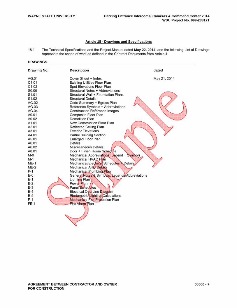
WAYNE STATE UNIVERSITY Parking Entrance Intercoms/ Cameras & Command Center 2014 WSU Project No. 999-238171
AGREEMENT BETWEEN CONTRACTOR AND OWNER 00500 - 7 FOR CONSTRUCTION
Article 18 - Drawings and Specifications
18.1 The Technical Specifications and the Project Manual dated May 22, 2014, and the following List of Drawings represents the scope of work as defined in the Contract Documents from Article 4.
DRAWINGS Drawing No.: Description dated
AG.01 Cover Sheet + Index May 21, 2014 C1.01 Existing Utilities Floor Plan C1.02 Spot Elevations Floor Plan S0.00 Structural Notes + Abbreviations S1.01 Structural Wall + Foundation Plans S1.02 Structural Details AG.02 Code Summary + Egress Plan AG.03 Reference Symbols + Abbreviations AG.04 Construction Reference Images A0.01 Composite Floor Plan A0.02 Demolition Plan A1.01 New Construction Floor Plan A2.01 Reflected Ceiling Plan A3.01 Exterior Elevations A4.01 Partial Building Section A5.01 Enlarged Floor Plan A6.01 Details A6.02 Miscellaneous Details A8.01 Door + Finish Room Schedule M-0 Mechanical Abbreviations, Legend + Symbols M-1 Mechanical HVAC Plan ME-1 Mechanical/Electrical Schedules + Details ME-2 Mechanical AHU Details P-1 Mechanical Plumbing Plan E-0 General Notes & Symbols, Legends/Abbreviations E-1 Lighting Plan E-2 Power Plan E-3 Panel Schedules E-4 Electrical One Line Diagram E-5 Photometric Lighting Calculations F-1 Mechanical Fire Protection Plan FE-1 Fire Alarm Plan

WAYNE STATE UNIVERSITY Parking Entrance Intercoms/ Cameras & Command Center 2014 WSU Project No. 999-238171
AGREEMENT BETWEEN CONTRACTOR AND OWNER 00500 - 8 FOR CONSTRUCTION
IN WITNESS WHEREOF the parties to these presents have hereunto set their hands as of the day and year first written above. Signed, sealed and delivered in the presence of: CONTRACTOR’S NAME GOES HERE By__________________________________ signature ____________________________________ Please print name here ____________________________________ Date signed ____________________________________ Title _____________________________ Witness THE BOARD OF GOVERNORS of WAYNE STATE UNIVERSITY By_______________________________ Richard J. Nork, Vice President for Finance and Facilities __________________________ Date signed Form Contract Approved by OGC 06/13 – LG File_reference_here

WAYNE STATE UNIVERSITY Parking Entrance Intercoms/ Cameras & Command Center 2014 WSU Project No. 999-238171
FORM OF GUARANTEE 00510 - 1
FORM OF GUARANTEE PROJECT: Parking Entrance Intercoms/ Cameras & Command Center 2014 OWNER: BOARD OF GOVERNORS, WAYNE STATE UNIVERSITY CONTRACTOR: DATE: Know all men by these presents that, in consideration of my (our) having been awarded the Contract or Subcontract for complete furnishing and installation of: Parking Entrance Intercoms/ Cameras & Command Center 2014 (999-238171) For: Board of Governors, Wayne State University In conformity with drawings and specifications prepared by Architect or Engineer, Dokes Design + Architecture, LLC, and known as the buildings indicated above, I (we) do hereby agree that, should I (we) be notified that the said work has proved faulty, etc., that I (we) will return to the buildings within three (3) working days of the receipt of such notice, and will furnish the necessary labor and material to repair such work to the satisfaction of the Owner and without cost to the Owner. The Agreement shall remain in full force and effect for a one year period (DATE TBD) WITNESS: signed: Subcontractor by: address: city/state/zip: signed: General Contractor by: (THIS FORM TO BE FILED IN DUPLICATE.)

WAYNE STATE UNIVERSITY Parking Entrance Intercoms/ Cameras & Command Center 2014 WSU Project No. 999-238171
GENERAL CONDITIONS 00700 - 1
GENERAL CONDITIONS (Revised 10-2009) A. Although AIA Document A201 - Twelfth Edition (April 1970) - "General Conditions of the Contract for
Construction" is not bound herein, it forms a part of these construction documents. B. A reference copy of AIA Document A201 - Twelfth Edition (April 1970) - "General Conditions of the Contract for
Construction" is on file at the following location: Wayne State University Finance & Facilities Management Procurement & Strategic Sourcing Academic / Administrative Services Building 5700 Cass Avenue Detroit Michigan 48202

WAYNE STATE UNIVERSITY Parking Entrance Intercoms/ Cameras & Command Center 2014 WSU Project No. 999-238171
SUPPLEMENTARY GENERAL CONDITIONS 00800 - 1
SUPPLEMENTARY GENERAL CONDITIONS OF THE CONTRACT FOR CONSTRUCTION Facilities Planning & Management - Design & Construction Services Wayne State University
WAYNE STATE UNIVERSITY Parking Entrance Intercoms/ Cameras & Command Center 2014 WSU Project No. 999-238171
SUPPLEMENTARY GENERAL CONDITIONS 00800 - 2
WSU SUPPLEMENTARY GENERAL CONDITIONS OF THE CONTRACT FOR CONSTRUCTION NOTE: The following items related to A.I.A. General Conditions, A.I.A. Document A-201 - Twelfth Edition
(April 1970), by specific number being amended to. These items, as amendments, shall have precedence over the article being amended.
ARTICLE 1 - CONTRACT DOCUMENTS 1.1 DEFINITIONS 1.1.5 The Agreement
The Agreement executed by the Contractor and the Owner. 1.2 EXECUTION, CORRELATION, INTENT, AND INTERPRETATIONS 1.2.6 "General Conditions and "Supplementary General Conditions" apply with
equal force to all Contractors, Subcontractors work, and extra work required under this Contract. 1.2.7 Precedence of Drawings and Specifications.
The Agreement has precedence over WSU Supplementary General Conditions.
WSU Supplementary General Conditions have precedence over A.I.A. A-201 General Conditions of the Contract.
Specifications have precedence over drawings. Full-size drawings have precedence over scale drawings. Large-scale plans and details have precedence over small-scale plans and details. Figured dimensions have precedence over plans and elevations.
ARTICLE 2 - ARCHITECT 2.1 DEFINITION 2.1.1.1 The term Architect or Architect/Engineer as used in these specifications refers to Facilities Planning
and Management - Design Services, and/or Consulting Architect/Engineer. 2.2 ADMINISTRATION OF THE CONTRACT 2.2.16 The Architect will assign Field Representatives to make periodic visits to the project for the purpose
of assisting the Architect in carrying out his field responsibilities at the site. The duties, responsibilities and limitations of authority of any such Field Representative shall be as follows:
a. Explain Contract Documents: Assist the Contractor via the Contractor's Superintendent to
understand the intent of the Contract Documents.
b. Observations: Conduct on-site observations and spot checks of the work in progress as a basis for determining conformance of the work, material, and equipment with the Contract Documents.
c. Additional Information: Obtain from the Architect, additional details or information, if and when required, at the job site for proper execution of the work.
d. Modifications: Consider and evaluate suggestions or modifications that may be submitted
by the Contractor and report them with recommendations to the Architect for final decision.
e. Construction Schedule and Completion: Be alert to the completion, and report same to the Architect. When the construction work has been completed in accordance with the Contract Documents, advise the Architect that the work is ready for general inspection and

WAYNE STATE UNIVERSITY Parking Entrance Intercoms/ Cameras & Command Center 2014 WSU Project No. 999-238171
SUPPLEMENTARY GENERAL CONDITIONS 00800 - 3
acceptance.
f. Job Conferences: Attend and report to the Architect on all required conferences held at the job site.
g. Observe Tests: See that tests which are required by the Contract Documents are actually
conducted; observe, record and report to the Architect all details relative to the test procedures; and advise the architect's office in advance of the schedules of tests.
h. Inspection by Others: If inspectors, representing local, state or federal agencies having
jurisdiction over the project, visit the job site, accompany such inspectors during their trips through the project, record the outcome of these inspections, and report same to the Architect's office.
i. Shop Drawings: Do not permit the installation of any materials and equipment for which
shop drawings are required unless such drawings have been duly approved and issued by the Architect.
j. Contractor's Requisitions for Payment: Review and make recommendations to the
Architect for disposition.
k. List of Items for Correction: After substantial completion, make a list of items for correction before final inspection and check each item as it is corrected.
l. Owner's Occupancy of the Building: If the Owner occupies (to any degree) the building
prior to actual completion of the work by the Contractor, be especially alert to possibilities of claims for damage to completed work prior to the acceptance of the building.
m. Owner Existing Operation: In the case of additions to or Demolitions of an existing facility,
which must be maintained as an operational unit, be alert to conditions on the job site which may have an effect on the Owner's existing operation.
n. Limitations of Authority: Do not become involved in any of the following areas of
responsibility unless specific exceptions are established by written instructions issued by the Architect.
aa. Do not authorize deviations from the Contract Documents. bb. Avoid conducting any test personally.
cc. Do not enter into the area of responsibility of the Contractor's field
superintendent. dd. Do not expedite job for Contractor unless so instructed by the Architect.
ee. Do not advise on or issue directions relative to any aspect of the building
technique or sequence unless a specific technique or sequence is called for in the Specifications or by written instructions from the Architect.
ff. Do not approve shop drawings or samples.
gg. Do not authorize or advise the Owner to occupy the Project, in whole or in part,
prior to the final acceptance of the building.
hh. Do not issue a Certificate for Payment. ARTICLE 3 - OWNER 3.5 OWNER'S RIGHT TO DO WORK 3.5.1 The Owner may exercise his right, which is hereby acknowledged by the Contractor, to let
independent of the Contract for the work herein specified, any other work on the premises even if of

WAYNE STATE UNIVERSITY Parking Entrance Intercoms/ Cameras & Command Center 2014 WSU Project No. 999-238171
SUPPLEMENTARY GENERAL CONDITIONS 00800 - 4
like character and trades, and the Owner shall not be liable for any damage, loss or expense incurred by the Contractor through the fault of any other Contractor so employed by the Owner. The Contractor acknowledges the necessity of work by others, to be performed at approximately the same time as the work hereunder, and agrees to perform his work in full cooperation with the work of such other trades and/or Contractors, partially or entirely completed, by such other trades and/or Contractors, or by the Owner, when, in the opinion of the Architect, such access or use is necessary for the performance and completion of any portion or all of the work of others or of any work on the site.
3.6 OWNER'S ACCESS AND PARTIAL OCCUPANCY 3.6.1 The Owner shall have access to the work at all times, and at his election, may from time to time
(prior to the stipulated contract completion date) occupy any of the units or parts of the project as the work in connection therewith is complete to such a degree as will, in the opinion of the Owner, permit their temporary or permanent use. The Owner will, prior to any such partial occupancy, give notice to the Contractor thereof and such occupancy shall be upon the following terms:
a. Such occupancy shall not constitute an acceptance of work not performed in accordance
with the Contract nor shall such occupancy relieve the Contractor of liability to perform any work by the Contract by not complete at the time of occupancy.
b. Except as otherwise provided by an agreement at the time of such partial occupancy, the
Contractor shall be relieved of all maintenance costs on units or parts so occupied. c. The Contractor shall not be responsible for wear and tear or damage resulting from partial
occupancy.
d. The Owner shall assume risk of loss with respect to any unit or part so occupied.
e. The Contractor shall, if required by the Owner, furnish heat, light, water, or other such services to the units or parts occupied and the Owner shall make proper remuneration therefore to the Contractor.
3.6.2 The Contractor agrees that the Owner shall have the right, after seven (7) days' written notice to the Contractor, to place and install as much equipment and machinery during the progress of the work as is possible before the completion of the various parts of the work; and further agrees that such placing and installation of equipment shall not in any way evidence the completion of the work or any portion thereof, nor signify the Owner's acceptance of the work or any portion thereof. Should the Owner place or install such equipment and machinery with his own forces he shall be responsible for any damage to work of the Contractor caused by the Owner's work or workmen. Should the Owner have such placement or installation performed by another Contractor, then the Owner shall require said Contractor to be responsible for all such damage caused by his work, his workers, or his subcontractors.
ARTICLE 4 - CONTRACTOR 4.4 LABOR AND MATERIALS 4.4.3 All materials shall be so delivered, stored and handled to prevent the inclusion of foreign materials
and the damage of materials by water or breakage. Packaged materials shall be delivered and stored in original packages until ready for use. Packages or materials showing evidence of water or other damage shall be rejected. All materials shall be of the respective qualities specified herein.
4.4.4 The Contractor shall be responsible for the proper care and protection of all his materials,
equipment, etc., delivered at the site. Building materials, equipment, etc., may be stored on the premises subject to the approval of the Architect.
4.4.5 To insure timely availability of critical materials in case of national emergency, the Contractor may
order his subcontractors to proceed with fabrication of the same earlier than required by normal sequence of construction. In the event storage facilities are not available on the site or at the source of fabrication, the Owner will endeavor to provide such storage space as may be available to care for same. Where this is necessary, the Contractor shall be paid for all stored material on the

WAYNE STATE UNIVERSITY Parking Entrance Intercoms/ Cameras & Command Center 2014 WSU Project No. 999-238171
SUPPLEMENTARY GENERAL CONDITIONS 00800 - 5
Owner's property or on the properties approved by the Owner upon approval of certified invoices. It shall be the Contractor's obligation to pay for all handling costs and damage to this material. The Contractor shall protect this property against damage.
4.6 TAXES 4.6.1 The Bidder shall include in his proposal and make payment of all Federal, State, County and
Municipal taxes including Michigan State Sales and Use Taxes, now in force or which may be enacted during the progress and completion of the work covered.
4.7 PERMITS, FEES AND NOTICES 4.7.3 The Contractor shall pay highway or DPW fees for damages to sidewalks, streets, or other public
property or to any public utilities. 4.7.4 Permits and licenses of a temporary nature necessary for the execution of the work shall be
secured and paid for by the Contractor. 4.7.5 Except for the General Building Permit (which is not required), the Contractor shall secure
and pay for all other required permits, including the following:
Electrical - State of Michigan Plumbing - State of Michigan Mechanical - State of Michigan Elevator - City of Detroit
4.7.6 The Contractor shall secure certificates of inspection and of occupancy that may be required by
authorities having jurisdiction over the work. These certificates shall be delivered to the Architect upon completion of the work.
4.9 SUPERINTENDENT 4.9.2 The Contractor shall give sufficient supervision to the work, using his best skill and attention. He
shall carefully study and compare all drawings, specifications, and other instructions, and shall at once report to the Architect any error, inconsistency, or omission which he may discover, but he shall not be held responsible for their existence or discovery.
4.9.3 The Contractor's superintendent shall periodically inspect the entire project to make certain that all
of the stipulations of all of the articles of the General Conditions are being observed. 4.12 DRAWINGS AND SPECIFICATIONS AT THE SITE 4.12.1.1 Refer to Paragraph 4.12.1, of A.I.A. General Conditions of the Contract for Construction. Modify
the last sentence of this paragraph to read:
"The Drawings, marked to record all changes made during construction, shall be incorporated in the Contractor's 'Informational Package'."
4.12.2 As a basic and interim step for the fulfillment of the "Informational Package", accurate records of all
non-structural underground and concealed work shall be kept, including, but not limited to, all piping, conduit, equipment, and drainage and tunnel work. In addition, such records shall be available for review during various steps of the project.
4.13 SHOP DRAWINGS AND SAMPLES 4.13.9 Immediately before and as a condition of substantial completion, the Contractor shall provide the
Owner an "Informational Package" and instructional sessions on the operation, maintenance, and service of the facility. The "Informational Package" shall include:
1. One (1) set of transparency (sepia) of the approved shop drawings and

WAYNE STATE UNIVERSITY Parking Entrance Intercoms/ Cameras & Command Center 2014 WSU Project No. 999-238171
SUPPLEMENTARY GENERAL CONDITIONS 00800 - 6
descriptive material submitted during construction. Any shop documents unobtainable in sepia shall be supplied in three (3) sets.
2. One (1) set of transparency (sepia) of constructional shop drawings with all
installation revisions incorporated to reflect the as-built condition. Examples of constructional shop drawings are dimensioned conduit, piping and ductwork layout drawings.
3. Three (3) sets of instructional manuals on the installation, operation, maintenance and service of equipment and systems, including parts lists.
Examples of Specific Information Required:
1. Electrical
a. Conduit layout of light, power, and special systems, indicating dimensionally the
locations and size of runs; circuit grouping and conductor size and number in conduit runs.
b. System description and elementary diagrams, connection and interconnection diagrams, and device internal diagrams.
2. Mechanical
a. Piping and ductwork layout indicating dimensionally the location and size of the
runs.
b. Description and diagrams of control systems.
Following the submittal of the "Informational Package", the Contractor shall schedule and provide, at the Owner's convenience, instructional sessions for Owner's personnel to acquaint them with the operation, maintenance, and service of the system.
3. Elevators
a. Elementary diagrams and description of sequence of operation of the system
control components, connection and interconnection diagrams, and device internal diagrams.
ARTICLE 5 - SUBCONTRACTORS 5.2 AWARD OF SUBCONTRACTS AND OTHER CONTRACTS FOR PORTIONS OF THE WORK 5.2.3 Delete Article 5.2.3 in its entirety. 5.2.4 Delete Article 5.2.4 in its entirety. ARTICLE 7 - MISCELLANEOUS PROVISIONS (Revised 6-13-2011) 7.5 PERFORMANCE BOND AND LABOR AND MATERIAL PAYMENT BOND 7.5.1 The successful Bidder will be required to furnish a Performance Bond and Labor and Material
Payment bond in an amount equal to 100% of the contract award amount, and include such cost in the Proposal, complying with the laws of the State of Michigan. The graduated formula no longer applies.
A. Performance Bond and Labor and Material Payment Bond shall be from a surety company acceptable to the Owner and made payable as follows:
(1) A Labor and Material Payment bond for 100% of the contract award amount to the Board of
Governors of Wayne State University, and guaranteeing the payment of all subcontractors

WAYNE STATE UNIVERSITY Parking Entrance Intercoms/ Cameras & Command Center 2014 WSU Project No. 999-238171
SUPPLEMENTARY GENERAL CONDITIONS 00800 - 7
and all indebtedness incurred for labor, materials, or any cause whatsoever on account of the Contractor in accordance with the laws of the State of Michigan relating to such bonds.
(2) A Performance bond for 100% of the contract award amount to the Board of Governors of
Wayne State University to guarantee and insure the completion of work according to the Contract.
B. The only acceptable Performance Bond shall be the AIA A312 – 2010.
C. The Contractor shall include with his bid evidence of his ability to obtain a Performance Bond in the
amount of 100% of the bid amount, and in accordance with the terms and conditions outlined in this section, Such evidence shall be project specific and shall be submitted on a form provided by the Surety or Agent thereof.
7.7 ROYALTIES AND PATENTS 7.7.1 The Contractor hereby agrees to indemnify, protect and save harmless the Architect and the Owner
from and against any and all liability, loss or damage, and to reimburse the Owner and the Architect for any expenses, including legal fees and disbursements to which the Owner or the Architect may be put because of claims of litigation on account of infringement or alleged infringement of any letters patent or patent rights by reason of the work or materials, equipment, or other items used by the Contractor in its performance.
7.9 INTEREST 7.9.1 Delete Article 7.9 in its entirety.
ARTICLE 8 - TIME 8.1 DEFINITIONS 8.1.3 The Date of Substantial Completion of the Work is the Date certified by the Architect when
construction of the entire work is sufficiently complete, in accordance with the Contract Documents, so the Owner may occupy the Work for the use for which it is intended. It is the beginning date for the guarantees on all the Project Work.
8.3.5 LIQUIDATED DAMAGES
It is understood that if said Contract is not completed within the time specified in the Contract plus any extension of time thereto, the Contractor shall pay Liquidated Damages to the Owner as set forth in Article 11 of the Agreement between Contractor and Owner for Construction.
ARTICLE 9 - PAYMENT AND COMPLETION 9.3 PROGRESS PAYMENTS 9.3.1 On or before the 20th day of each month, the Contractor shall submit to the Architect on the
Owner's Standard Form, a written application for payment showing the proportionate value of the work installed to date from which shall be deducted, a reserve of 10% and all previous payments, and the balance of the amount as approved by the Architect shall be due and payable to the Contractor on or about the 15th day of the succeeding month.
9.3.2.2 No payments will be made because of materials or equipment stored off the site, except as
provided for in Subparagraph 4.4.5 of the Supplementary General Conditions or other special cases the Owner may approve.
9.6 FAILURE OF PAYMENT 9.6.1 Delete Article 9.6 in its entirety. ARTICLE 11 - INSURANCE (Revised 3-22-2012)

WAYNE STATE UNIVERSITY Parking Entrance Intercoms/ Cameras & Command Center 2014 WSU Project No. 999-238171
SUPPLEMENTARY GENERAL CONDITIONS 00800 - 8
11.1 CONTRACTOR'S LIABILITY INSURANCE 11.1.2 The insurance required by Subparagraph 11.1.1 shall be written for not less than any limits of
liability specified herein, or required by law, whichever is greater, and shall include contractual liability insurance as applicable to the Contractor's obligations under Paragraph 4.18.
During the life of the Contract, the Contractor shall maintain the following types of insurance:
A. General Requirements
Type of Insurance Minimum Requirement
1.Comprehensive General Bodily Injury $ 500,000 each person
Liability $1,000,000 aggregate
Property Damage $ 500,000 each occurrence $1,000,000 aggregate
or $2,000,000 combined single limit (CSL)
2.Fire Legal Liability $ 100,000
3.Comprehensive Automobile Bodily Injury $ 500,000 each person Liability (including $1,000,000 each accident
Hired and non-owned Property Damage $ 500,000 each accident vehicles)
or $2,000,000 combined single limit (CSL)
4.Workers'Compensation Statutory - Michigan (Employer's Liability) $100,000
5.Property - All Risk In an amount sufficient to cover the total value of the contractor's
property in the care, custody or control of WSU.
B. Maximum Acceptable Deductibles
Type of Insurance Maximum Deductible
Comprehensive General Liability $5,000 Fire Legal Liability $5,000 Comprehensive Automobile Liability -0- Workers' Compensation -0- Property - All Risk $ 500
11.1.3 The Board of Governors, Wayne State University, shall be named as an additional insured but only with respect to accidents arising out of the performance of said contract. The contractor shall prepare a certificate of insurance which shall name the “Office of Risk Management; 5700 Cass Avenue” as the Wayne State University certificate holder.
11.1.3.1 The Contractor shall either 1) require each of his Subcontractors to procure and to maintain during
the life of his subcontract, Subcontractors' Comprehensive General Liability, Automobile Liability and Property Damage Liability Insurance of the type and in the same amounts as specified in the Subparagraph, or 2) insure the activity of his subcontractors in his own policy.
11.2 OWNER'S LIABILITY INSURANCE Delete Article 11.2 in its entirety.
11.3 PROPERTY INSURANCE Delete Article 11.3 in its entirety and replace with the following:

WAYNE STATE UNIVERSITY Parking Entrance Intercoms/ Cameras & Command Center 2014 WSU Project No. 999-238171
SUPPLEMENTARY GENERAL CONDITIONS 00800 - 9
11.3.1 The Contractor shall purchase and maintain property insurance upon the entire work at the site to
the full insurable value thereof. This insurance shall include the interests of the Owner, the Contractor, Subcontractors, and sub-subcontractors in the work and shall insure against the perils of Fire, Extended Coverage, Vandalism, and Malicious Mischief.
11.3.2 The Owner and Contractor waive all rights against each other for damages caused by fires or other
perils to the extent covered by insurance provided under Subparagraph 11.3.1. The Contractor shall require similar waivers by Subcontractors and sub-subcontractors in accordance with Clause 5.3.1.5.
11.3.3 Insurance must be issued by an insurance company with an “A rating as denoted in the AM Best
Key Rating Guide”. ARTICLE 12 - CHANGES IN THE WORK 12.1 CHANGE ORDERS 12.1.8 Percentage markups in pricing under Subparagraphs 12.1.3.1, 12.1.3.3, and 1.2.4 shall be as
limited in the Contract Documents. Unit price of Subparagraph 12.1.3.2 shall represent total unit cost to the Owner and shall include the Contractor's markup for overhead and profit.
ARTICLE 14 - TERMINATION OF THE CONTRACT 14.1 TERMINATION BY THE CONTRACTOR 14.1.1 If the work is stopped for a period of thirty days under any order of any court or other public
authority having jurisdiction, or as a result of any act of government, such as a declaration of a national emergency making materials unavailable, through no act or fault of the contract or a subcontractor or their agents or employees or other persons performing any of the Work under a contract with the contractor, then the contractor may, upon seven days' written notice to the Owner and the Architect, terminate the contract and recover from the Owner payment for all Work executed and for any proven loss sustained upon any materials, equipment, tools, construction equipment, and machinery, including reasonable profit and damages.
ARTICLE 15 - ADDITIONAL CONDITIONS 15.1 SUBSTITUTION OF MATERIALS AND EQUIPMENT 15.1.1 Whenever a material, article, or piece of equipment is identified on the Drawings or in the
Specifications by reference to manufacturers' or vendors' names, trade names, catalog numbers, or the like, it is so identified for the purpose of establishing a standard, and any material, article, or piece of equipment of other manufacturers or vendors, which will perform adequately the duties imposed by the general design will be considered equally acceptable provided the material, article, or piece of equipment so proposed is, in the opinion of the Architect, of equal substance, appearance, and function. It shall not be purchased or installed by the Contractor without the Architect's written approval.
15.2 NON-DISCRIMINATION PROVISION AND WAGE AND HOUR ACT 15.2.1 During the performance of this contract, the Contractor agrees as follows: 15.2.1.1 The Contractor shall not discriminate against any employee or applicant for employment because of
sex, race, creed, color, age, or national origin. The Contractor will take affirmative action to insure that applicants are employed, and that employees are treated during employment without regard to their sex, race, age, creed, color, or national origin.
15.2.1.2 Such action shall include but not be limited to, the following: employment; upgrading; demotion; or
transfer; recruitment or recruitment advertising; layoff or terminations; rates of pay or other forms of compensation; and selection for training, including apprenticeship. The Contractor agrees to post

WAYNE STATE UNIVERSITY Parking Entrance Intercoms/ Cameras & Command Center 2014 WSU Project No. 999-238171
SUPPLEMENTARY GENERAL CONDITIONS 00800 - 10
in conspicuous places, available to employees and applicants for employment, notices to be provided setting forth the provisions of this non-discrimination clause.
15.2.1.3 The Contractor will, in all solicitations, or advertisements for employees, placed by or on behalf of
the contractor, state that all qualified applicants will receive consideration for employment without regard to sex, race, creed, color, age or national origin.
15.2.1.4 The Contractor will send to each labor union or representative of workers with which he has a
collective bargaining agreement or other contract or understanding, a notice advising the labor union or worker's representative of the Contractor's commitments under Section 202 of Executive Order No. 11246 of October 27, 1965, and shall post copies of the notice in conspicuous places available to employees and applicants for employment.
15.2.1.5 The Contractor will comply with all provisions of the Executive Order No. 11246 of October 27,
1965, and of the rules, regulations and relevant orders of the Secretary of Labor or other government agency or authority having jurisdiction.
15.2.1.6 The Contractor will furnish all information and reports required by Executive Order No. 11246 of
October 27, 1965, and by the rules, regulations, and orders of the Secretary of Labor or other government agency or authority having jurisdiction, and will permit access to his books, records, and accounts by the administrative agency and the Secretary of Labor for the purposes of investigation to ascertain compliance with such rules, regulations and orders.
15.2.1.7 In the event of the Contractor's noncompliance with the non-discrimination clauses of this contract,
or with any of the said rules, regulations, or orders, this Contract may be canceled, terminated or suspended in whole or in part, and the Contractor may be declared ineligible for further University contracts or federally-assisted contracts in accordance with procedure authorized in Executive Order No. 11246 of October 27, 1965, or by rule, regulation, or order of the Secretary of Labor or other government agency or authority having jurisdiction.
15.2.1.8 The Contractor will include in the provisions of Subparagraph 15.2.1.1 through 15.2.1.8 in every
subcontract or purchase order unless exempted by rules, regulations or orders of the President's Committee on Equal Employment Opportunity issued pursuant to Section 204 of Executive Order No. 11246 of September 14, 1965, so that provisions will be binding upon each subcontractor or vendor. The Contractor will take such action with respect to any subcontract or purchase order as the administering agency may direct as a means of enforcing such provisions including sanctions for noncompliance: Provided, however, that in the event the Contractor becomes involved as a result of such direction by the administering agency, the Contractor may request the United States to enter into such litigation to protect the interest of the United States.
15.3 COMPLIANCE WITH COPELAND ANTI-KICKBACK ACT AND REGULATIONS 15.3.1 The Contractor shall comply with the Copeland Anti-Kickback Act and Regulations of the Secretary
of Labor (29CFR, Part 3) which are herein incorporated by reference. 15.4 PREVAILING WAGES 15.4.1 Contractors and subcontractors shall pay all mechanics and laborers, including apprentices and
trainees, no less than the wage and fringe benefit rates prevailing in the locality in which the work is performed. Wage and fringe benefit rates are determined by the Federal Government Department of Labor.
15.4.2 Classifications not provided in the schedule shall be determined prior to the award of the contract
and shall be no less than the wage and fringe benefit rates determined by the Federal Department of Labor.
15.4.3 Contractors and subcontractors shall adhere to the ratios of apprentices to journey workers as
determined by the Federal Department of Labor. 15.4.4 Contractors and subcontractors shall keep a copy of the prescribed wage and benefit rates posted
at the construction site in a conspicuous place.

WAYNE STATE UNIVERSITY Parking Entrance Intercoms/ Cameras & Command Center 2014 WSU Project No. 999-238171
SUPPLEMENTARY GENERAL CONDITIONS 00800 - 11
15.4.5 Contractors and subcontractors shall keep an accurate record of the name, occupation, and the
actual benefits paid to each mechanic or laborer for the contract. This record shall be made available for reasonable inspection by the Federal Department of Labor and the Owner.

WAYNE STATE UNIVERSITY Parking Entrance Intercoms/ Cameras & Command Center 2014 WSU Project No. 999-238171
DRAWINGS 00850 - 1
DRAWINGS The Technical Specifications dated May 21, 2014 and the following List of Drawings represent the scope of work as defined in the Contract Documents from Article 4. DRAWINGS Drawing No.: Description Date AG.01 Cover Sheet + Index May 21, 2014 C1.01 Existing Utilities Floor Plan C1.02 Spot Elevations Floor Plan S0.00 Structural Notes + Abbreviations S1.01 Structural Wall + Foundation Plans S1.02 Structural Details AG.02 Code Summary + Egress Plan AG.03 Reference Symbols + Abbreviations AG.04 Construction Reference Images A0.01 Composite Floor Plan A0.02 Demolition Plan A1.01 New Construction Floor Plan A2.01 Reflected Ceiling Plan A3.01 Exterior Elevations A4.01 Partial Building Section A5.01 Enlarged Floor Plan A6.01 Details A6.02 Miscellaneous Details A8.01 Door + Finish Room Schedule M-0 Mechanical Abbreviations, Legend + Symbols M-1 Mechanical HVAC Plan ME-1 Mechanical/Electrical Schedules + Details ME-2 Mechanical AHU Details P-1 Mechanical Plumbing Plan E-0 General Notes & Symbols, Legends/Abbreviations E-1 Lighting Plan E-2 Power Plan E-3 Panel Schedules E-4 Electrical One Line Diagram E-5 Photometric Lighting Calculations F-1 Mechanical Fire Protection Plan FE-1 Fire Alarm Plan

WAYNE STATE UNIVERSITY Parking Entrance Intercoms/ Cameras & Command Center 2014 WSU Project No. 999-238171
GENERAL REQUIREMENTS 01000 - 1
GENERAL REQUIREMENTS
GENERAL A. CONTRACTOR'S RESPONSIBILITY It is not the responsibility of the Architect/Engineer or Owner's Representative to notify the Contractor or
subcontractors when to commence, to cease, or to resume work; nor in any way to superintend so as to relieve the Contractor of responsibility or of any consequences of neglect or carelessness by him or his subordinates. All material and labor shall be furnished at times best suited for all Contractors and subcontractors concerned, so that the combined work of all shall be properly and fully completed on the date fixed by the Contract.
The Contractor shall be responsible for all items contained in both the specifications and on the drawings for all
trades. He shall be responsible for the proper division of labor according to current labor union agreements regardless of the division of responsibility implied in the contract documents.
B. CODES AND STANDARDS Reference to standard specifications for workmanship, apparatus, equipment and materials shall conform to the
requirements of latest specifications of the organization referenced, i.e., American Society for Testing Materials (ASTM), Underwriters Laboratories, Inc. (UL), American National Standards Institute, Inc. (ANSI), and others so listed in the Technical Specifications.
C. PERMITS, FEES AND NOTICES See Supplementary General Conditions. D. MEASUREMENTS Before proceeding with each Work Item, Contractor shall locate, mark and measure any quantity or each item and
report quantities to Engineer. If measured quantities exceed Engineer’s estimate, Contractor shall obtain written authorization to proceed from Owner before executing Work required for that Work Item.
Measurement of quantities for individual Work Items will be performed by Contractor and reviewed by Engineer.
Coordinate measurements with inspection as required in Section “Coordination.” Cost of Work included in Work Item for quantities as indicated in Contract Documents shall be included in Base
Bid. 1. Additions to or deductions from lump sum price for quantities of each Work Item added to or deducted
from Work respectively shall be at unit prices indicated in Bid Form and shall constitute payment or deductions in full for all material, equipment, labor, supervision and incidentals necessary to complete Work.
E. CONTRACTOR'S MEASUREMENTS Before ordering material, preparing Shop Drawings, or doing any work, each Contractor shall verify, at the building,
all dimensions which may affect his work. He assumes full responsibility for the accuracy of his figures. No allowance for additional compensation will be considered for minor discrepancies between dimensions on the drawings and actual field dimensions.
F. CONTINUITY OF SERVICE (Revised 3-26-2012) Continuity of all existing services in the building shall be maintained throughout the construction period. Where it is
necessary to tie into the existing electrical service, water or waste systems, it shall be done as directed by the Architect/Engineer. This Contract shall also provide temporary lines or bypasses that may be required to maintain continuous service in the building. All utility shutdowns must be approved by the Owners Representative / Project Manager, not less than 7 business days prior to the event, so that proper notification can be posted.
WAYNE STATE UNIVERSITY Parking Entrance Intercoms/ Cameras & Command Center 2014 WSU Project No. 999-238171
GENERAL REQUIREMENTS 01000 - 2
G. SUBMITTALS All submittals (except Shop Drawings) and samples required by the Specifications shall be submitted in triplicate
unless otherwise specified for a particular item under an individual Specification Section. Each sample shall be clearly identified on a tag attached, showing the name of the Project Consultant, the project
number and title, the names of the Contractor, manufacturer (and supplier if same is not the manufacturer), the brand name or number identification, pattern, color, or finish designation and the location in the work.
Each submittal shall be covered by a transmittal letter, properly identified with the project title and number and a
brief description of the item being submitted. Contractor shall be responsible for all costs of packing, shipping and incidental expenses connected with delivery
of the samples to the Project Consultant or other designated address. If the initial sample is not approved, prepare and submit additional sets until approval is obtained. Materials supplied or installed which do not conform to the appearance, quality, profile, texture or other determinant
of the approval samples will be rejected, and shall be replaced with satisfactory materials at the Contractor's expense.
H. GENERAL/STANDARD ELECTRONIC EQUIPMENT AND INFRASTRUCTURE REQUIREMENTS (Revised
11-2008)
1. Compliance with WSU Standards for Communications Infrastructure
A. All applicable work, products, materials and methods shall comply with the latest version of the “WSU Standards for Communications Infrastructure” except as where noted.
B. This document is available at the following website/URL: http://networks.wayne.edu/WSU-
Communications-Standards.pdf 2. Automation System Program Code
A. All automation system uncompiled and compiled program codes, source codes, custom modules, graphical user interface screen shots and any other automation system programming data and material (Program Code) shall be provided to the UNIVERSITY in hard copy and on CD Rom in an unencrypted format acceptable to the UNIVERSITY.
B. Copyright for the Program Code shall be assigned to the UNIVERSITY for purposes of system
maintenance.
PROTECTION OF OCCUPANCY (Revised 3-2006) A. FIRE PRECAUTIONS Take necessary actions to eliminate possible fire hazards and to prevent damage to construction work, building
materials, equipment, temporary field offices, storage sheds, and other property. During the construction, provide the type and quantity of fire extinguishers and fire hose to meet safety and fire
prevention practices by National Fire Protection Association (NFPA) Codes and Standards (available at http://www.nfpa.org/ )
In the event that construction includes "hot work", the contractor shall provide the Owner's Representative
with a copy of their hot work policy, procedures, or permit program. No hot work activity (temporary maintenance, renovation, or construction by operation of a gas or electrically powered equipment which produces flames, sparks or heat that is sufficient to start a fire or ignite combustible materials) shall be performed until such documents are provided. During such operations, all highly combustible or flammable materials shall be removed from the immediate working area, and if removal is impossible, same shall be protected with flame retardant shield.

WAYNE STATE UNIVERSITY Parking Entrance Intercoms/ Cameras & Command Center 2014 WSU Project No. 999-238171
GENERAL REQUIREMENTS 01000 - 3
Not more than one-half day's supply of flammable liquids such as gasoline, spray paint and paint solvent shall be
brought into the building at any one time. Flammable liquids having a flash point of 100 degrees F. or below which must be brought into the building shall be confined in an Underwriters Laboratories (UL) labeled safety cans. The bulk supply of flammables shall be stored at least 75 feet from the building and other combustible materials. Spigots on drums containing flammable liquids are prohibited on the project site. Drums shall be equipped with approved vented pumps, and be grounded and bonded.
Only a reasonable working supply of combustible building materials shall be located inside the building. All oil-soaked rags, papers, and other similar combustible materials shall be removed from the building at the close
of each day's work, or more often if necessary, and placed in metal containers, with self-closing lids. Materials and equipment stored in cardboard cartons, wood crates or other combustible containers shall be stored
in an orderly manner and accessibly located, fire-fighting equipment of approved types shall be placed in the immediate vicinity of any materials or equipment stored in this type of crate or carton.
No gasoline, benzene, or like flammable materials shall be poured into sewers, manholes, or traps. All rubbish shall be removed from the site and legally disposed of. Burning of rubbish, waste materials or trash on
the site shall not be permitted. The contractor shall be responsible for the conduct of employees relative to smoking and all smoking shall be in
the area designated by the Architect/Engineer. B. GENERAL SAFETY AND BUILDING PRECAUTIONS Provide and maintain in good repair barricades, railings, etc., as required by law for the protection of the Public. All
exposed material shall be smoothly dressed. At dangerous points throughout the work environment provide and maintain colored lights or flags in addition to
above guardrails. Isolate Owner's occupied areas from areas where demolition and alteration work will be done, with temporary,
dustproof, weatherproof, and fireproof enclosures as conditions may require and as directed by the Architect/Engineer.
Cover and protect furniture, equipment and fixtures to remain from soiling, dust, dirt, or damage when demolition
work is performed in rooms or areas from which such items have not been removed. Protect openings made in the existing roofs, floors, and other construction with weatherproof coverings, barricades,
and temporary fire rated partitions to prevent accidents. Repair any damage done to existing work caused by the construction and removal of temporary partitions,
coverings, and barricades. The Contractor will be held responsible for all breakage or other damage to glass up to the time the work is
completed. Provide protection for existing buildings, interior and exterior, finishes, walls, drives, landscaping, lawns (see
below), etc. All damages shall be restored to match existing conditions to the satisfaction of the Architect/Engineer. The Contractor and Owner will define the anticipated area of lawn damage at the project Pre-Construction Meeting.
Whether the lawn is sparse or fully developed, any lawn damaged due to the Contractor's work will be replaced with sod by the University. The University's unit cost of $10.00 per square yard and landscaping at a rate of 1.5 times the cost of the sod repairs, the full cost of which will be assessed against the Contractor. At the completion of the project, a deductive Change Order reflecting this cost will be issued.
The Contractor is to include an allowance in his bid for this corrective work.

WAYNE STATE UNIVERSITY Parking Entrance Intercoms/ Cameras & Command Center 2014 WSU Project No. 999-238171
GENERAL REQUIREMENTS 01000 - 4
C. INTERFERENCE WITH OWNER'S OPERATIONS The Owner will be utilizing the Building Facilities to carry on his normal business operation during construction.
The Contractor shall schedule performance of the work necessary to complete the project in such a way as to interfere as little as possible with the operation during construction. The Contractor shall schedule performance of the work necessary to complete the project in such a way as to interfere as little as possible with the operation of the Owner.
Work which will interfere with the Owner's occupancy, including interruptions to the Owner's mechanical and
electrical services, and essentially noisy operations (such as jackhammering) shall be scheduled in advance. The schedule of alterations shall be approved by the Architect/Engineer and the work shall be done in accordance with the approved schedule.
It is understood that the work is to be carried through to completion with the utmost speed consistent with good
workmanship and to meet the construction schedule. The Contractor shall begin work under the Contract without delay upon receipt of the fully-executed contract and
shall substantially complete the project ready for unobstructed occupancy and use of the Owner for the purposes intended within the completion time stated in the contract.
The Contractor shall, immediately upon award of contract, schedule his work and expedite deliveries of materials
and performance of subcontractors to maintain the necessary pace to meet the construction schedule. CONTRACTOR'S REPRESENTATION AND COORDINATION A. FIELD SUPERINTENDENT Contractor shall assign a full time project manager/superintendent for the duration of the project. This person shall
be experienced and qualified in all phases of the work and shall be present at the site during Contractor’s working hours. The project manager shall have Contractor’s full authority to represent Contractor in all routine operations including payment, changes to the work, and scheduling. Contractor shall not re-assign this individual without prior written permission of the Owner.
B. MEETINGS When directed by the Architect/Engineer, meetings shall be held for the purpose of coordinating and expediting the
work. The invited contractors or subcontractors will be required to have qualified representatives at these meetings, empowered to act in their behalf.
C. COORDINATION The Contractor shall also provide a staff adequate to coordinate and expedite the work properly and shall at all
times maintain competent supervision of its own work and that of its subcontractors to insure compliance with contract requirements.
The Contractor shall be solely responsible for all construction means, methods, techniques, sequences, and
procedures and for coordinating all portions of the work under the Contractor. D. CONSTRUCTION SCHEDULE The Construction Schedule shall be prepared after the award of contract. Soon after, a pre-construction meeting is
held with the Owner and the Architect/Engineer to determine the areas to which the Contractor will be allowed access at any one time.
The Contractor is alerted to the fact that areas in which he will be working will be occupied by students and employees of the University as well as the general public. The Contractor's access, to and from the project site, will be confined to limited areas so as not to unduly disrupt the normal activities of the University. TEMPORARY FACILITIES

WAYNE STATE UNIVERSITY Parking Entrance Intercoms/ Cameras & Command Center 2014 WSU Project No. 999-238171
GENERAL REQUIREMENTS 01000 - 5
A. GENERAL The following temporary facilities descriptions represent standard conditions. Verify accuracy with
Architect/Engineer at time of bids. B. CONTRACTOR’S OFFICE Provide field offices as required. Locate temporary field offices on site where directed by Architect/Engineer. Appearance and location of field offices shall be approved by the Architect/Engineer. Provide for all other administrative facilities and storage off the Owner's property. C. STORAGE OF MATERIALS All materials shall be stored in areas designated by the Architect/Engineer. All stored materials shall be arranged
for the minimum disruption to occupants and to allow full access to and throughout the building. Materials stored outdoors shall be neat and orderly and covered to prevent damage or vandalism.
D. PARKING 1. GENERAL University parking regulations will be strictly enforced. Maintain Owner's parking areas free of dirt and debris resulting from operations under the contract. 2. STANDING AND UNLOADING/LOADING VEHICLES All Contractors are to call Wayne State University Public Safety at 577-2222, and give at least 24 hours
advance notice that they have vehicles that must be at the job site. Vehicles will be permitted at the project site only as long as the vehicles are needed for
loading/unloading, and must be immediately moved upon completion. All unauthorized and/or unattended standing vehicles will be subject to ticketing and removal by
University Police. Towed vehicles may be reclaimed by calling 577-2222, and paying any assessed charges.
3. COMPLIMENTARY PARKING There is no complimentary parking for Contractor’s employee vehicles.
4. WAYNE STATE UNIVERSITY PUBLIC/STUDENT PARKING AREAS
Public Parking, on a first-come first-served basis is available. Contact the office of the One Card System, at 313.577.9513 for information on availability of parking on a contractual basis.
E. TOILET FACILITIES The Owner's designated existing toilet facilities may be used by workers on the project. Contractor shall maintain
such facilities in a neat and sanitary condition. F. TELEPHONE USE If required, the Contractor shall provide and pay for a temporary telephone within the building for his use and that of
his subcontractors. No use of the Owner's telephone (except pay telephones) will be permitted.
WAYNE STATE UNIVERSITY Parking Entrance Intercoms/ Cameras & Command Center 2014 WSU Project No. 999-238171
GENERAL REQUIREMENTS 01000 - 6
G. ACCESS DEVICES The Contractor shall furnish and maintain temporary hoists, ladders, railings, scaffolds, runways, and the like as
required for safe, normal access to the permanent construction until the permanent facilities are complete. Each trade shall furnish such additional means of access as may be required for the progress and completion of the work. Such temporary access devices shall meet all applicable local, state, and federal codes and regulations.
H. HEAT AND VENTILATION Provide cold weather protection and temporary heat and ventilation as required during construction to protect the
work from freezing and frost damage. Provide adequate ventilation as required to maintain reasonable interior building air conditions and temperatures,
to prevent accumulation of excess moisture, and to remove construction fumes. Tarpaulins and other materials used for temporary enclosures. Coverings and protection shall be flameproofed. I. WATER SERVICE Sources of water are available at the site. The Owner will pay for reasonable amounts of water used for
construction purposes. The Contractor shall provide, at the earliest possible date, temporary connections to the water supply sources and
maintain adequate distribution for all construction requirements. The Contractor shall protect sources against damage.
Methods of conveying this water shall be approved by the Architect/Engineer and shall not interfere with the
Owner's operations. J. ELECTRICAL SERVICES All charges for reasonable amounts of electrical power energy used for temporary lighting and power required for
this work will be paid by the Owner. The Contractor shall provide and maintain any temporary electrical lighting and power required for this work. At the
completion of the work, all such temporary electrical facilities shall be removed and disposed of by the Contractor. Temporary lighting and power shall comply with the regulations and requirements of the National Electrical Code
INSPECTIONS AND TESTS The Architect/Engineer shall at all times have access to the work wherever it is in preparation or in progress and
the Contractor shall provide proper facilities for such access and for observation. No failure of the Architect/Engineer, during the progress of the work, to discover or reject materials or work not in
accordance with the Contract Specifications and Drawings shall be deemed an acceptance thereof nor a waiver of defects therein. Likewise, no acceptance or waiver shall be inferred or implied due to payments made to contractor or by partial or entire occupancy of the work, or installation of materials that are not strictly in accordance with the Contract Specifications and Drawings.
Where tests are specifically called for in the Specifications, the Owner shall pay all costs of such tests and
engineering services unless otherwise stated in the contract. Where tests are not specifically called for in the Specifications, but are required by the Architect/Engineer or
Consultant, the Owner shall pay all costs of such tests and engineering services unless the tests reveal that the workmanship or materials used by the Contractor are not in conformity with the Drawings, Specifications, and/or approved shop drawings. In such event, the Contractor shall pay for the tests, shall remove all work and materials so failing to conform and replace with work and materials that are in full conformity.
CLEAN-UP

WAYNE STATE UNIVERSITY Parking Entrance Intercoms/ Cameras & Command Center 2014 WSU Project No. 999-238171
GENERAL REQUIREMENTS 01000 - 7
The Contractor shall at all times keep the Owner's premises and the adjoining premises, driveways and streets
clean of rubbish caused by the Contractor's operations and at the completion of the work shall remove all the rubbish, all of his tools, equipment, temporary work and surplus materials, from and about the premises, and shall leave the work clean and ready for use. If the contractor does not attend to such cleaning immediately upon request, the Architect/Engineer may cause such cleaning to be done by others and charge the cost of same to the Contractor.
The Contractor will be responsible for all damage from fire that originates in, or is propagated by, accumulations of
rubbish or debris. All rubbish and debris shall be disposed of off the Owner's property in an approved sanitary landfill site. No open
burning of debris or rubbish will be permitted. Job site shall be left neat and clean at the completion of each day's operation.
PROJECT CLOSE-OUT
A. RECORD DRAWINGS At beginning of job, provide one copy of Working Drawings, and record changes, between Working Drawings and
"As Builts", including changes made by Addenda, Change Orders, Shop Drawings, etc. These shall be kept up to date. Update to indicate make of all mechanical and electrical equipment and fixtures installed. Keep these Record Prints in good condition and available for inspection by the Architect/Engineer.
Upon completion of the job, turn over to the Architect/Engineer Record Prints of Working Drawings showing all job
changes. B. OPERATING AND MAINTENANCE DATA Prepare and furnish to the Architect/Engineer three (3) bound copies of "Operating and Maintenance Manual" on
all equipment installed under this Contract. Manual shall include copies of all Manufacturers' "Operating and Service Instructions", including Parts List, Control
Diagrams, Description of Control Systems, Operating, Electrical Wiring, and any other information needed to understand, operate and maintain the equipment. The names and addresses of all subcontractors shall be included. These instructions shall be custom-prepared for this job -- catalog cuts will not be accepted. Equipment shall be cross-referenced to Section of Specifications and to location shown and scheduled on drawings.
Include Test-Adjust-Balance Report in the Manual. C. FINAL INSPECTION Secure final inspections from the State of Michigan as soon as the work is completed and immediately submit such
Certificates to the Architect/Engineer. D. GUARANTEES (See Sections 00510 and 01781) Guarantees on material and labor from the General Contractor and his subcontractors shall be as required in
Sections 00510 and 01781. E. SWORN STATEMENT AND WAIVER OF LIENS (revised 4-11-2012) Prior to final payment, the General Contractor shall provide a Contractor's Sworn Statement and Full Unconditional
Waivers of Liens from all subcontractors for material and labor and from all suppliers who provide materials exceeding $1,000. Sworn Statements and signed waivers from all Subcontractors must accompany Pay Applications or they will be returned for such documentation prior to approval.
ASBESTOS HAZARD

WAYNE STATE UNIVERSITY Parking Entrance Intercoms/ Cameras & Command Center 2014 WSU Project No. 999-238171
GENERAL REQUIREMENTS 01000 - 8
A. The contractor shall not start any work in any area that has not been inspected for asbestos by the Owner's Industrial Hygiene Department, or a qualified representative of the Owner and approval is given for work to be done. If asbestos is found, safety measures as recommended by the Owner's Industrial Hygiene Department, or a qualified representative of the Owner, shall be completed, or approval given for work to be done before work is started. The contractor shall not perform any asbestos removal or containment work under the contract.
KEYS
A. The Owner shall provide the contractor keys on loan to have access to the various spaces in order to complete the
contract. Contractor will sign for and be responsible for each key on loan, returnable to Owner upon completion of the contract. In case of any lost keys, the Owner will backcharge the contract $250.00 for each core change. In the event that a Contractor wants access to a secured area, he shall give the Owner a minimum 48-hour notice.
WAYNE STATE UNIVERSITY Parking Entrance Intercoms/ Cameras & Command Center 2014 WSU Project No. 999-238171
SUMMARY OF WORK SUMMARY OF WORK PROJECT: Parking Entrance Intercoms/ Cameras & Command Center 2014 WSU PROJECT NO.: 999-238171 PROJECT MANAGER: Robert Jacobs 1. EXAMINATION
The Contractor shall visit the site and become familiar with conditions under which he will be working. Also meet with the project manager and review site access, storage areas, etc.
2. Description of Work – Project includes project includes an addition and expansion of the current parking office in
Parking Structure 8. Work includes but is not limited to General Contract for all disciplines including Civil, Structural, Architectural, Plumbing, HVAC, Electrical and other trades as necessary. .
3. The building is located at
Wayne State University 71 West Forest Detroit, Michigan 48202

Wayne State University Parking Entrance Intercoms/ Cameras & Command Center 2013 Detroit, Michigan WSU Project # 999-238171 PS8
PRODUCT REQUIREMENTS 016000 - 1
SECTION 016000 - PRODUCT REQUIREMENTS
PART 1 - GENERAL
1.1 RELATED DOCUMENTS
A. Drawings, Wayne State University Construction Design Standards Sept. 2012, and general provisions of the Contract, including General and Supplementary Conditions and other Division 01 Specifications Sections, apply to this Section.
1.2 SUMMARY
A. This Section includes administrative and procedural requirements for selection of products for use in Project; product delivery, storage, and handling; manufacturers' standard warranties on products; special warranties; product substitutions; and comparable products.
1. Substitutions Request Procedures.
2. Product Substitutions and Options.
3. Substitution Request Form
1.3 DEFINITIONS
A. Products: Items purchased for incorporating into the Work, whether purchased for Project or taken from previously purchased stock. The term "product" includes the terms "material," "equipment," "system," and terms of similar intent.
1. Named Products: Items identified by manufacturer's product name, including make or model number or other designation shown or listed in manufacturer's published product literature, that is current as of date of the Contract Documents.
2. New Products: Items that have not previously been incorporated into another project or facility. Products salvaged or recycled from other projects are not considered new products.
3. Comparable Product: Product that is demonstrated and approved through submittal process, or where indicated as a product substitution, to have the indicated qualities related to type, function, dimension, in-service performance, physical properties, appearance, and other characteristics that equal or exceed those of specified product.
B. Substitutions (after selection of successful bidder): Changes in products, materials, equipment, and methods of construction from those required by the Contract Documents and proposed by Contractor.
Wayne State University Parking Entrance Intercoms/ Cameras & Command Center 2013 Detroit, Michigan WSU Project # 999-238171 PS8
PRODUCT REQUIREMENTS 016000 - 2
C. Basis-of-Design Product Specification: Where a specific manufacturer's product is named and accompanied by the words "basis of design," including make or model number or other designation, to establish the significant qualities related to type, function, dimension, in-service performance, physical properties, appearance, and other characteristics for purposes of evaluating comparable products of other named manufacturers.
D. Manufacture’s Warranty: Preprinted written warranty published by individual manufacturer for a particular product and specifically endorsed by manufacturer to Owner.
1.4 SUBMITTALS
A. Substitution Requests: Submit (3) copies of each request for consideration. Identify product or fabrication or installation method to be replaced. Include Specification Section number and title and Drawing numbers and titles.
1. Substitution Request must be proposed and submitted only to the General Contractor. Substitution Request must not be sent directly to the Architect.
2. Substitution Request Form: Use Standard form. 3. Documentation: Show compliance with requirements for substitutions and the
following, as applicable:
a. Statement indicating why specified material or product cannot be provided. b. Coordination information, including a list of changes or modifications
needed to other parts of the Work and to construction performed by Owner and separate contractors, that will be necessary to accommodate proposed substitution.
c. Detailed comparison of significant qualities of proposed substitution with those of the Work specified. Significant qualities may include attributes such as performance, weight, size, durability, visual effect, and specific features and requirements indicated.
d. Product Data, including drawings and descriptions of products and fabrication and installation procedures.
e. Samples, where applicable or requested. f. List of similar installations for completed projects with project names and
addresses and names and addresses of architects and owners. g. Material test reports from a qualified testing agency indicating and
interpreting test results for compliance with requirements indicated. h. Research/evaluation reports evidencing compliance with building code in
effect for Project, from a model code organization acceptable to authorities having jurisdiction.
i. Detailed comparison of Contractor's Construction Schedule using proposed substitution with products specified for the Work, including effect on the overall Contract Time. If specified product or method of construction cannot be provided within the Contract Time, include letter from

Wayne State University Parking Entrance Intercoms/ Cameras & Command Center 2013 Detroit, Michigan WSU Project # 999-238171 PS8
PRODUCT REQUIREMENTS 016000 - 3
manufacturer, on manufacturer's letterhead, stating lack of availability or delays in delivery.
j. Cost information, including a proposal of change, if any, in the Contract Sum.
k. Contractor's certification that proposed substitution complies with requirements in the Contract Documents and is appropriate for applications indicated.
l. Contractor's waiver of rights to additional payment or time that may subsequently become necessary because of failure of proposed substitution to produce indicated results.
4. Architect/Engineer shall have the right to reject proposed substitution without explanation.
5. Architect's Action: If necessary, Architect will request additional information or documentation for evaluation within (7) days of receipt of a request for substitution. Architect will notify Contractor of acceptance or rejection of proposed substitution within 15 days of receipt of request, or (7) days of receipt of additional information or documentation, whichever is later.
a. Should the Architect not respond within twelve (12) calendar days of the dated date of Request, the proposed substitution is considered REJECTED.
b. Form of Acceptance: Construction Change Directive. c. Use product specified if Architect cannot make a decision on use of a
proposed substitution within time allocated.
B. Basis-of-Design Product Specification Submittal: Comply with requirements in Division 01 Section "Submittal Procedures." Show compliance with requirements.
1.5 QUALITY ASSURANCE
A. Compatibility of Options: If Contractor is given option of selecting between two or more products for use on Project, product selected shall be compatible with products previously selected, even if previously selected products were also options.
1.6 PRODUCT DELIVERY, STORAGE, AND HANDLING
A. Deliver, store, and handle products using means and methods that will prevent damage, deterioration, and loss, including theft. Comply with manufacturer's written instructions.
B. Delivery and Handling:
1. Schedule delivery to minimize long-term storage at Project site and to prevent overcrowding of construction spaces.
Wayne State University Parking Entrance Intercoms/ Cameras & Command Center 2013 Detroit, Michigan WSU Project # 999-238171 PS8
PRODUCT REQUIREMENTS 016000 - 4
2. Coordinate delivery with installation time to ensure minimum holding time for items that are flammable, hazardous, easily damaged, or sensitive to deterioration, theft, and other losses.
3. Deliver products to Project site in an undamaged condition in manufacturer's original sealed container or other packaging system, complete with labels and instructions for handling, storing, unpacking, protecting, and installing.
4. Inspect products on delivery to ensure compliance with the Contract Documents and to ensure that products are undamaged and properly protected.
C. Storage:
1. Store products to allow for inspection and measurement of quantity or counting of units.
2. Store materials in a manner that will not endanger Project structure. 3. Store products that are subject to damage by the elements, under cover in a
weathertight enclosure above ground, with ventilation adequate to prevent condensation.
4. Store cementitious products and materials on elevated platforms. 5. Store foam plastic from exposure to sunlight, except to extent necessary for
period of installation and concealment. 6. Comply with product manufacturer's written instructions for temperature,
humidity, ventilation, and weather-protection requirements for storage. 7. Protect stored products from damage and liquids from freezing.
1.7 PRODUCT WARRANTIES
A. Warranties specified in other Sections shall be in addition to, and run concurrent with, other warranties required by the Contract Documents. Manufacturer's disclaimers and limitations on product warranties do not relieve Contractor of obligations under requirements of the Contract Documents.
1. Manufacturer's Warranty: Preprinted written warranty published by individual manufacturer for a particular product and specifically endorsed by manufacturer to Owner.
2. Special Warranty: Written warranty required by or incorporated into the Contract Documents, either to extend time limit provided by manufacturer's warranty or to provide more rights for Owner.
B. Special Warranties: Prepare a written document that contains appropriate terms and identification, ready for execution. Submit a draft for approval before final execution.
1. Manufacturer's Standard Form: Modified to include Project-specific information and properly executed.
2. Specified Form: When specified forms are included with the Specifications, prepare a written document using appropriate form properly executed.
3. Refer to Divisions 2 through 16 Sections for specific content requirements and particular requirements for submitting special warranties.

Wayne State University Parking Entrance Intercoms/ Cameras & Command Center 2013 Detroit, Michigan WSU Project # 999-238171 PS8
PRODUCT REQUIREMENTS 016000 - 5
C. Submittal Time: Comply with requirements in Division 01 Section "Closeout Procedures."
PART 2 - PRODUCTS
2.1 PRODUCT SELECTION PROCEDURES
A. General Product Requirements: Provide products that comply with the Contract, that are undamaged and, unless otherwise indicated, that are new at time of installation.
1. Provide products complete with accessories, trim, finish, fasteners, and other items needed for a complete installation and indicated use and effect.
2. Standard Products: If available, and unless custom products or nonstandard options are specified, provide standard products of types that have been produced and used successfully in similar situations on other projects.
3. Owner reserves the right to limit selection to products with warranties not in conflict with requirements of the Contract Documents.
4. Where products are accompanied by the term "as selected," Architect will make selection.
5. Where products are accompanied by the term "match sample," sample to be matched is Architect's.
6. Descriptive, performance, and reference standard requirements in the Specifications establish "salient characteristics" of products.
B. Product Selection Procedures:
1. Product: Where Specifications name a single product and manufacturer, provide the named product that complies with requirements.
2. Manufacturer/Source: Where Specifications name a single manufacturer or source, provide a product by the named manufacturer or source that complies with requirements.
3. Products: Where Specifications include a list of names of both products and
manufacturers, provide one of the products listed that complies with requirements.
4. Manufacturers: Where Specifications include a list of manufacturers' names, provide a product by one of the manufacturers listed that complies with requirements.
5. Available Products: Where Specifications include a list of names of both
products and manufacturers, provide one of the products listed, or an unnamed product, that complies with requirements. Comply with provisions in Part 2 "Comparable Products" Article for consideration of an unnamed product.
6. Available Manufacturers: Where Specifications include a list of manufacturers,

Wayne State University Parking Entrance Intercoms/ Cameras & Command Center 2013 Detroit, Michigan WSU Project # 999-238171 PS8
PRODUCT REQUIREMENTS 016000 - 6
provide a product by one of the manufacturers listed, or an unnamed manufacturer, that complies with requirements. Comply with provisions in Part 2 "Comparable Products" Article for consideration of an unnamed product.
7. Product Options: Where Specifications indicate that sizes, profiles, and
dimensional requirements on Drawings are based on a specific product or system, provide the specified product or system. Comply with provisions in Part 2 "Product Substitutions" Article for consideration of an unnamed product or system.
8. Basis-of-Design Product: Where Specifications name a product and include a list of manufacturers, provide the specified product or a comparable product by one of the other named manufacturers. Drawings and Specifications indicate sizes, profiles, dimensions, and other characteristics that are based on the product named. Comply with provisions in Part 2 "Comparable Products" Article for consideration of an unnamed product by the other named manufacturers.
9. Visual Matching Specification: Where Specifications require matching an established Sample, select a product that complies with requirements and matches Architect's sample. Architect's decision will be final on whether a proposed product matches.
a. If no product available within specified category matches and complies with other specified requirements, comply with provisions in Part 2 "Product Substitutions" Article for proposal of product.
10. Visual Selection Specification: Where Specifications include the phrase "as selected from manufacturer's colors, patterns, textures" or a similar phrase, select a product that complies with other specified requirements.
a. Standard Range: Where Specifications include the phrase "standard range of colors, patterns, textures" or similar phrase, Architect will select color, pattern, density, or texture from manufacturer's product line that does not include premium items.
b. Full Range: Where Specifications include the phrase "full range of colors, patterns, textures" or similar phrase, Architect will select color, pattern, density, or texture from manufacturer's product line that includes both standard and premium items.
2.2 PRODUCT SUBSTITUTIONS
A. Timing: Architect will consider requests for substitution if received within 30 days after the “Notice to Proceed”. Requests received after that time may be considered or rejected at discretion of Architect.
B. Conditions: Architect will consider Contractor's request for substitution when the following conditions are satisfied. If the following conditions are not satisfied, Architect will return requests without action, except to record noncompliance with these

Wayne State University Parking Entrance Intercoms/ Cameras & Command Center 2013 Detroit, Michigan WSU Project # 999-238171 PS8
PRODUCT REQUIREMENTS 016000 - 7
requirements:
1. Requested substitution offers Owner a substantial advantage in cost, time, energy conservation, or other considerations, after deducting additional responsibilities Owner must assume. Owner's additional responsibilities may include compensation to Architect for redesign and evaluation services, increased cost of other construction by Owner, and similar considerations.
2. Requested substitution does not require extensive revisions to the Contract Documents.
3. Requested substitution is consistent with the Contract Documents and will produce indicated results.
4. Substitution request is fully documented and properly submitted. 5. Requested substitution will not adversely affect Contractor's Construction
Schedule. 6. Requested substitution has received necessary approvals of authorities having
jurisdiction. 7. Requested substitution is compatible with other portions of the Work. 8. Requested substitution has been coordinated with other portions of the Work. 9. Requested substitution provides specified warranty.
2.3 COMPARABLE PRODUCTS
A. Conditions: Architect will consider Contractor's request for comparable product when the following conditions are satisfied. If the following conditions are not satisfied, Architect will return requests without action, except to record noncompliance with these requirements:
1. Evidence that the proposed product does not require extensive revisions to the Contract Documents, that it is consistent with the Contract Documents and will produce the indicated results, and that it is compatible with other portions of the Work.
2. Detailed comparison of significant qualities of proposed product with those named in the Specifications. Significant qualities include attributes such as performance, weight, size, durability, visual effect, and specific features and requirements indicated.
3. Evidence that proposed product provides specified warranty. 4. List of similar installations for completed projects with project names and
addresses and names and addresses of architects and owners, if requested. 5. Samples, if requested.
PART 3 - EXECUTION (Not Used)
END OF SECTION 016000

Wayne State University Parking Entrance Intercoms/ Cameras & Command Center 2013 Detroit, Michigan WSU Project # 999-238171 PS8
EXECUTION 017300 - 1
SECTION 017300 – EXECUTION
PART 1 - GENERAL
1.1 RELATED DOCUMENTS
A. Drawings, Wayne State University Construction Design Standards Sept. 2012, and general provisions of the Contract, including General and Supplementary Conditions and other Division 01 Specifications Sections, apply to this Section.
1.2 SUMMARY
A. This Section includes general procedural requirements governing execution of the work including, but not limited to, the following:
1. Construction layout. 2. General installation of products. 3. Progress cleaning. 4. Starting and adjusting. 5. Protection of installed construction. 6. Correction of the Work.
B. Related Sections include the following:
1. Division 017329 Section “Cutting and Patching” for procedural requirements for cutting and patching necessary for the installation or performance of other components of the Work.
2. Division 017700 Section “Closeout Procedures” for submitting final property survey with Project Record Documents, recording of Owner-accepted deviations from indicated lines and level of final cleaning.
1.3 SUBMITTALS
A. Landfill Receipts: Submit copy of receipts issued by a landfill facility, licensed to accept hazardous materials, for hazardous waste disposal.
PART 2 - PRODUCTS (Not Used)
PART 3 - EXECUTION
3.1 EXAMINATION

Wayne State University Parking Entrance Intercoms/ Cameras & Command Center 2013 Detroit, Michigan WSU Project # 999-238171 PS8
EXECUTION 017300 - 2
A. Existing Conditions: The existence and location of site improvements, utilities, and other construction indicated as existing are not guaranteed. Before beginning work, investigate and verify the existence and location of mechanical and electrical systems and other construction affecting the Work.
1. Before construction, verify the location and points of connection of utility services.
B. Existing Utilities: The existence and location of underground and other utilities and construction indicated as existing are not guaranteed. Before beginning sitework, investigate and verify the existence and location of underground utilities and other construction affecting the Work.
1. Before construction, verify the location and invert elevation at points of connection of sanitary sewer, storm sewer, and water-service piping; and underground electrical services.
2. Furnish location data for work related to Project that must be performed by public utilities serving Project site.
C. Acceptance of Conditions: Examine substrates, areas, and conditions, with Installer or Applicator present where indicated, for compliance with requirements for installation tolerances and other conditions affecting performance. Record observations.
1. Verify compatibility with and suitability of substrates, including compatibility with existing finishes or primers.
2. Examine roughing-in for mechanical and electrical systems to verify actual locations of connections before equipment and fixture installation.
3. Examine walls, floors, and roofs for suitable conditions where products and systems are to be installed.
4. Proceed with installation only after unsatisfactory conditions have been corrected. Proceeding with the Work indicates acceptance of surfaces and conditions.
3.2 PREPARATION
A. Existing Utility Information: Furnish information to local utility, Owner and Architect that is necessary to adjust, move, or relocate existing utility structures, utility poles, lines, services, or other utility appurtenances located in or affected by construction. Coordinate with authorities having jurisdiction.
B. Field Measurements: Take field measurements as required to fit the Work properly. Recheck measurements before installing each product. Where portions of the Work are indicated to fit to other construction, verify dimensions of other construction by field measurements before fabrication. Coordinate fabrication schedule with construction progress to avoid delaying the Work.
C. Existing Utility Interruptions: Do not interrupt utilities serving facilities occupied by Owner or others unless permitted under the following conditions; and then only after

Wayne State University Parking Entrance Intercoms/ Cameras & Command Center 2013 Detroit, Michigan WSU Project # 999-238171 PS8
EXECUTION 017300 - 3
arranging to provide temporary utility services according to requirements indicated.
1. Notify Owner and Architect not less than seven (7) calendar days in advance of proposed utility interruptions. Provide information on length of interruptions.
2. Do not proceed with utility interruptions without Owner’s written permission.
D. Space Requirements: Verify space requirements and dimensions of items shown diagrammatically on Drawings.
E. Review of Contract Documents and Field Conditions: Immediately on discovery of the need for clarification of the Contract Documents, submit a request for information to Architect. Include a detailed description of problem encountered, together with recommendations for changing the Contract Documents.
3.3 CONSTRUCTION LAYOUT
A. Verification: Before proceeding to lay out the Work, verify layout information shown on Drawings, in relation to the property survey and existing benchmarks. If discrepancies are discovered, notify Architect promptly.
B. General: Engage a land surveyor professional engineer to lay out the Work using accepted surveying practices.
1. Establish benchmarks and control points to set lines and levels of construction and elsewhere as needed to locate each element of Project.
2. Establish dimensions within tolerances indicated. Do not scale Drawings to obtain required dimensions.
3. Inform installers of lines and levels to which they must comply. 4. Check the location, level and plumb, of every major element as the Work
progresses. 5. Notify Architect when deviations from required lines and levels exceed allowable
tolerances. 6. Close site surveys with an error of closure equal to or less than the standard
established by authorities having jurisdiction.
C. Site Improvements: Locate and lay out site improvements, including pavements, grading, fill and topsoil placement, utility slopes, and invert elevations.
D. Building Lines and Levels: Locate and lay out control lines and levels for structures, building foundations, column grids, and floor levels, including those required for mechanical and electrical work. Transfer survey markings and elevations for use with control lines and levels. Level foundations from two or more locations.
E. Record Log: Maintain a log of layout control work. Record deviations from required lines and levels. Include beginning and ending dates and times of surveys, weather conditions, name and duty of each survey party member, and types of instruments and tapes used. Make the log available for reference by Architect.
Wayne State University Parking Entrance Intercoms/ Cameras & Command Center 2013 Detroit, Michigan WSU Project # 999-238171 PS8
EXECUTION 017300 - 4
3.4 INSTALLATION
A. General: Locate the Work and components of the Work accurately, in correct alignment and elevation, as indicated.
1. Make vertical work plumb and make horizontal work level. 2. Where space is limited, install components to maximize space available for
maintenance and ease of removal for replacement. 3. Conceal pipes, ducts, and wiring in finished areas, unless otherwise indicated.
B. Comply with manufacturer's written instructions and recommendations for installing products in applications indicated.
C. Install products at the time and under conditions that will ensure the best possible results. Maintain conditions required for product performance until Substantial Completion.
D. Conduct construction operations so no part of the Work is subjected to damaging operations or loading in excess of that expected during normal conditions of occupancy.
E. Tools and Equipment: Do not use tools or equipment that produce harmful noise levels.
F. Templates: Obtain and distribute to the parties involved templates for work specified to be factory prepared and field installed. Check Shop Drawings of other work to confirm that adequate provisions are made for locating and installing products to comply with indicated requirements.
G. Anchors and Fasteners: Provide anchors and fasteners as required to anchor each component securely in place, accurately located and aligned with other portions of the Work.
1. Mounting Heights: Where mounting heights are not indicated, mount components at heights directed by Architect.
2. Allow for building movement, including thermal expansion and contraction. 3. Coordinate installation of anchorages. Furnish setting drawings, templates, and
directions for installing anchorages, including sleeves, concrete inserts, anchor bolts, and items with integral anchors, that are to be embedded in concrete or masonry. Deliver such items to Project site in time for installation.
H. Joints: Make joints of uniform width. Where joint locations in exposed work are not indicated, arrange joints for the best visual effect. Fit exposed connections together to form hairline joints.
I. Hazardous Materials: Use products, cleaners, and installation materials that are not considered hazardous.

Wayne State University Parking Entrance Intercoms/ Cameras & Command Center 2013 Detroit, Michigan WSU Project # 999-238171 PS8
EXECUTION 017300 - 5
3.5 PROGRESS CLEANING
A. General: Clean Project site and work areas daily, including common areas. Coordinate progress cleaning for joint-use areas where more than one installer has worked. Enforce requirements strictly. Dispose of materials lawfully.
1. Comply with requirements in NFPA 241 for removal of combustible waste materials and debris.
2. Do not hold materials more than (7) days during normal weather or (3) days if the temperature is expected to rise above 80 deg F (27 deg C).
3. Containerize hazardous and unsanitary waste materials separately from other waste. Mark containers appropriately and dispose of legally, according to regulations.
B. Site: Maintain Project site free of waste materials and debris.
C. Work Areas: Clean areas where work is in progress to the level of cleanliness necessary for proper execution of the Work.
1. Remove liquid spills promptly. 2. Where dust would impair proper execution of the Work, broom-clean or vacuum
the entire work area, as appropriate.
D. Installed Work: Keep installed work clean. Clean installed surfaces according to written instructions of manufacturer or fabricator of product installed, using only cleaning materials specifically recommended. If specific cleaning materials are not recommended, use cleaning materials that are not hazardous to health or property and that will not damage exposed surfaces.
E. Concealed Spaces: Remove debris from concealed spaces before enclosing the space.
F. Exposed Surfaces in Finished Areas: Clean exposed surfaces and protect as necessary to ensure freedom from damage and deterioration at time of Substantial Completion.
G. Waste Disposal: Burying or burning waste materials on-site will not be permitted. Washing waste materials down sewers or into waterways will not be permitted.
H. During handling and installation, clean and protect construction in progress and adjoining materials already in place. Apply protective covering where required to ensure protection from damage or deterioration at Substantial Completion.
I. Clean and provide maintenance on completed construction as frequently as necessary through the remainder of the construction period. Adjust and lubricate operable components to ensure operability without damaging effects.
J. Limiting Exposures: Supervise construction operations to assure that no part of the

Wayne State University Parking Entrance Intercoms/ Cameras & Command Center 2013 Detroit, Michigan WSU Project # 999-238171 PS8
EXECUTION 017300 - 6
construction, completed or in progress, is subject to harmful, dangerous, damaging, or otherwise deleterious exposure during the construction period.
3.6 STARTING AND ADJUSTING
A. Start equipment and operating components to confirm proper operation. Remove malfunctioning units, replace with new units, and retest.
B. Adjust operating components for proper operation without binding. Adjust equipment for proper operation.
C. Test each piece of equipment to verify proper operation. Test and adjust controls and safeties. Replace damaged and malfunctioning controls and equipment.
D. Manufacturer's Field Service: If a factory-authorized service representative is required to inspect field-assembled components and equipment installation, comply with qualification requirements in Division 01 Section "Quality Requirements."
3.7 PROTECTION OF INSTALLED CONSTRUCTION
A. Provide final protection and maintain conditions that ensure installed Work is without damage or deterioration at time of Substantial Completion.
B. Comply with manufacturer's written instructions for temperature and relative humidity.
3.8 CORRECTION OF THE WORK
A. Repair or remove and replace defective construction. Restore damaged substrates and finishes. Comply with requirements in Division 01 Section 017329 "Cutting and Patching".
1. Repairing includes replacing defective parts, refinishing damaged surfaces, touching up with matching materials, and properly adjusting operating equipment.
B. Restore permanent facilities used during construction to their specified condition.
C. Remove and replace damaged surfaces that are exposed to view if surfaces cannot be repaired without visible evidence of repair.
D. Repair components that do not operate properly. Remove and replace operating components that cannot be repaired.
E. Remove and replace chipped, scratched, and broken glass or reflective surfaces.
END OF SECTION 017300

Wayne State University Parking Entrance Intercoms/ Cameras & Command Center 2013 Detroit, Michigan WSU Project # 999-238171 PS8
CUTTING AND PATCHING 017329 - 1
SECTION 017329 - CUTTING AND PATCHING
PART 1 - GENERAL
1.1 RELATED DOCUMENTS
A. Drawings, Wayne State University Construction Design Standards Sept. 2012, and general provisions of the Contract, including General and Supplementary Conditions and other Division 01 Specifications Sections, apply to this Section.
B. Cutting: Removal of in-place construction necessary to permit installation or performance of other Work.
C. Patching: Fitting and repair work required to restore surfaces to original conditions after installation of other Work.
PART 2 - SUMMARY
A. This Section includes procedural requirements for cutting and patching.
B. See Divisions 2 through 16 Sections for specific requirements and limitations applicable to cutting and patching individual parts of the Work.
C. See Division 07 Section "Penetration Firestopping" for patching fire-rated construction.
2.2 QUALITY ASSURANCE
A. Structural Elements: Do not cut and patch structural elements in a manner that could change their load-carrying capacity or load-deflection ratio.
B. Operational Elements: Do not cut and patch operating elements and related components in a manner that results in reducing their capacity to perform as intended or that results in increased maintenance or decreased operational life or safety
C. Miscellaneous Elements: Do not cut and patch miscellaneous elements or related components in a manner that could change their load-carrying capacity, that results in reducing their capacity to perform as intended, or that results in increased maintenance or decreased operational life or safety
D. Visual Requirements: Do not cut and patch construction in a manner that results in visual evidence of cutting and patching. Do not cut and patch construction exposed on the exterior or in occupied spaces in a manner that would, in Architect's opinion, reduce the building's aesthetic qualities. Remove and replace construction that has been cut and patched in a visually unsatisfactory manner.

Wayne State University Parking Entrance Intercoms/ Cameras & Command Center 2013 Detroit, Michigan WSU Project # 999-238171 PS8
CUTTING AND PATCHING 017329 - 2
2.3 WARRANTY
A. Existing Warranties: Remove, replace, patch, and repair materials and surfaces cut or damaged during cutting and patching operations, by methods and with materials so as not to void existing warranties.
PART 3 - PRODUCTS
3.1 MATERIALS
A. General: Comply with requirements specified in other Sections.
B. In-Place Materials: Use materials identical to in-place materials. For exposed surfaces, use materials that visually match in-place adjacent surfaces to the fullest extent possible.
1. If identical materials are unavailable or cannot be used, use materials that, when installed, will match the visual and functional performance of in-place materials.
PART 4 - EXECUTION
4.1 EXAMINATION
A. Examine surfaces to be cut and patched and conditions under which cutting and patching are to be performed.
1. Compatibility: Before patching, verify compatibility with and suitability of substrates, including compatibility with in-place finishes or primers.
2. Proceed with installation only after unsafe or unsatisfactory conditions have been corrected.
4.2 PREPARATION
A. Temporary Support: Provide temporary support of Work to be cut.
B. Protection: Protect in-place construction during cutting and patching to prevent damage. Provide protection from adverse weather conditions for portions of Project that might be exposed during cutting and patching operations.
C. Adjoining Areas: Avoid interference with use of adjoining areas or interruption of free passage to adjoining areas.
D. Existing Utility Services and Mechanical/Electrical Systems: Where existing services/systems are required to be removed, relocated, or abandoned, bypass such
Wayne State University Parking Entrance Intercoms/ Cameras & Command Center 2013 Detroit, Michigan WSU Project # 999-238171 PS8
CUTTING AND PATCHING 017329 - 3
services/systems before cutting to minimize interruption to occupied areas.
4.3 PERFORMANCE
A. General: Employ skilled workers to perform cutting and patching. Proceed with cutting and patching at the earliest feasible time, and complete without delay.
1. Cut in-place construction to provide for installation of other components or performance of other construction, and subsequently patch as required to restore surfaces to their original condition.
B. Cutting: Cut in-place construction by sawing, drilling, breaking, chipping, grinding, and similar operations, including excavation, using methods least likely to damage elements retained or adjoining construction. If possible, review proposed procedures with original Installer; comply with original Installer's written recommendations.
1. In general, use hand or small power tools designed for sawing and grinding, not hammering and chopping. Cut holes and slots as small as possible, neatly to size required, and with minimum disturbance of adjacent surfaces. Temporarily cover openings when not in use.
2. Finished Surfaces: Cut or drill from the exposed or finished side into concealed surfaces.
3. Concrete and Masonry: Cut using a cutting machine, such as an abrasive saw or a diamond-core drill.
4. Excavating and Backfilling: Comply with requirements in applicable Division 31 Sections where required by cutting and patching operations.
5. Mechanical and Electrical Services: Cut off pipe or conduit in walls or partitions
to be removed. Cap, valve, or plug and seal remaining portion of pipe or conduit to prevent entrance of moisture or other foreign matter after cutting.
6. Proceed with patching after construction operations requiring cutting are
complete.
C. Patching: Patch construction by filling, repairing, refinishing, closing up, and similar operations following performance of other Work. Patch with durable seams that are as invisible as possible. Provide materials and comply with installation requirements specified in other Sections.
1. Inspection: Where feasible, test and inspect patched areas after completion to demonstrate integrity of installation.
2. Exposed Finishes: Restore exposed finishes of patched areas and extend finish restoration into retained adjoining construction in a manner that will eliminate evidence of patching and refinishing.
3. Floors and Walls: Where walls or partitions that are removed extend one

Wayne State University Parking Entrance Intercoms/ Cameras & Command Center 2013 Detroit, Michigan WSU Project # 999-238171 PS8
CUTTING AND PATCHING 017329 - 4
finished area into another, patch and repair floor and wall surfaces in the new space. Provide an even surface of uniform finish, color, texture, and appearance. Remove in-place floor and wall coverings and replace with new materials, if necessary, to achieve uniform color and appearance.
4. Ceilings: Patch, repair, or rehang in-place ceilings as necessary to provide an even-plane surface of uniform appearance.
5. Exterior Building Enclosure: Patch components in a manner that restores enclosure to a weathertight condition.
D. Cleaning: Clean areas and spaces where cutting and patching are performed. Completely remove paint, mortar, oils, putty, and similar materials.
END OF SECTION 017329
Wayne State University Parking Entrance Intercoms/ Cameras & Command Center 2013 Detroit, Michigan WSU Project # 999-238171 PS8
CLOSEOUT PROCEDURES 017700 - 1
SECTION 017700 - CLOSEOUT PROCEDURES
PART 1 - GENERAL
1.1 RELATED DOCUMENTS
A. Drawings, Wayne State University Construction Design Standards Sept. 2012, and general provisions of the Contract, including General and Supplementary Conditions and other Division 01 Specifications Sections, apply to this Section.
1.2 SUMMARY
A. This Section includes administrative and procedural requirements for contract closeout, including, but not limited to, the following: 1. Inspection procedures. 2. Substantial Completion and Inspection procedures. 3. Final Completion and Inspection Procedures. 4. List of incomplete items (punch list) 5. Payment Procedures 6. Project Record Documents. 7. Operation and Maintenance manuals. 8. Warranties. 9. Final cleaning.
B. See Division 01 Section "Execution" for progress cleaning of Project Site.
C. See Division 01 Section "Operation and Maintenance Data" for operation and maintenance manual requirements.
D. See Divisions 02 through 49 Sections for specific closeout and special cleaning requirements for the Work in those Sections.
1.3 SUBSTANTIAL COMPLETION
A. Preliminary Procedures: Before requesting inspection for determining date of Substantial Completion, complete the following. List items below that are incomplete in request.
1. Prepare a list of items to be completed and corrected (punch list), the value of items on the list, and reasons why the Work is not complete.
2. Advise Owner of pending insurance changeover requirements. 3. Submit specific warranties, workmanship bonds, maintenance service
agreements, final certifications, and similar documents. 4. Obtain and submit releases permitting Owner unrestricted use of the Work and
Wayne State University Parking Entrance Intercoms/ Cameras & Command Center 2013 Detroit, Michigan WSU Project # 999-238171 PS8
CLOSEOUT PROCEDURES 017700 - 2
access to services and utilities. Include occupancy permits, operating certificates, and similar releases.
5. Prepare and submit Project Record Documents, operation and maintenance manuals, Final Completion construction photographs, damage or settlement surveys, property surveys, and similar final record information.
6. Deliver tools, spare parts, extra materials, and similar items to location designated by Owner. Label with manufacturer's name and model number where applicable.
7. Make final changeover of permanent locks and deliver keys to Owner. Advise Owner's personnel of changeover in security provisions.
8. Complete startup testing of systems. 9. Submit test/adjust/balance records. 10. Terminate and remove temporary facilities from Project site, along with mockups,
construction tools, and similar elements. 11. Advise Owner of changeover in heat and other utilities. 12. Complete final cleaning requirements, including touchup painting. 13. Touch up and otherwise repair and restore marred exposed finishes to eliminate
visual defects.
B. Inspection: Submit a written request for inspection for Substantial Completion. On receipt of request, Architect will either proceed with inspection or notify Contractor of unfulfilled requirements. Architect will prepare the Certificate of Substantial Completion after inspection or will notify Contractor of items, either on Contractor's list or additional items identified by Architect, that must be completed or corrected before certificate will be issued.
1. Reinspection: Request reinspection when the Work identified in previous inspections as incomplete is completed or corrected.
2. Results of completed inspection will form the basis of requirements for Final Completion.
1.4 FINAL COMPLETION
A. Preliminary Procedures: Before requesting final inspection for determining date of Final Completion, complete the following:
1. Submit a final Application for Payment according to Division 01 Section "Payment Procedures."
2. Submit certified copy of Architect's Substantial Completion inspection list of items to be completed or corrected (punch list), endorsed and dated by Architect. The certified copy of the list shall state that each item has been completed or otherwise resolved for acceptance.
3. Submit evidence of final, continuing insurance coverage complying with insurance requirements.
4. Submit pest-control final inspection report and warranty.

Wayne State University Parking Entrance Intercoms/ Cameras & Command Center 2013 Detroit, Michigan WSU Project # 999-238171 PS8
CLOSEOUT PROCEDURES 017700 - 3
B. Inspection: Submit a written request for final inspection for acceptance. On receipt of request, Architect will either proceed with inspection or notify Contractor of unfulfilled requirements. Architect will prepare a final Certificate for Payment after inspection or will notify Contractor of construction that must be completed or corrected before certificate will be issued.
1. Reinspection: Request reinspection when the Work identified in previous inspections as incomplete is completed or corrected.
1.5 LIST OF INCOMPLETE ITEMS (PUNCH LIST)
A. Preparation: Submit (2) copies of list. Include name and identification of each space and area affected by construction operations for incomplete items and items needing correction including, if necessary, areas disturbed by Contractor that are outside the limits of construction.
1. Organize list of spaces in sequential order, starting with exterior areas first and proceeding from lowest floor to highest floor.
2. Organize items applying to each space by major element, including categories for ceiling, individual walls, floors, equipment, and building systems.
3. Include the following information at the top of each page: Project name, Date, Name of Architect and Owner, Name of Contractor, and Page Number.
1.6 WARRANTIES
A. Submittal Time: Submit written warranties on request of Architect for designated portions of the Work where commencement of warranties other than date of Substantial Completion is indicated.
B. Organize warranty documents into an orderly sequence based on the table of contents of the Project Manual.
1. Bind warranties and bonds in heavy-duty, 3-ring, vinyl-covered, loose-leaf binders, thickness as necessary to accommodate contents, and sized to receive 8-1/2-by-11-inch paper.
2. Provide heavy paper dividers with plastic-covered tabs for each separate warranty. Mark tab to identify the product or installation. Provide a typed description of the product or installation, including the name of the product and the name, address, and telephone number of Installer.
3. Identify each binder on the front and spine with the typed or printed title "WARRANTIES," Project name, and name of Contractor.
C. Provide additional copies of each warranty to include in operation and maintenance manuals.

Wayne State University Parking Entrance Intercoms/ Cameras & Command Center 2013 Detroit, Michigan WSU Project # 999-238171 PS8
CLOSEOUT PROCEDURES 017700 - 4
PART 2 - PRODUCTS
2.1 MATERIALS
A. Cleaning Agents: Use cleaning materials and agents recommended by manufacturer or fabricator of the surface to be cleaned. Do not use cleaning agents that are potentially hazardous to health or property or that might damage finished surfaces.
PART 3 - EXECUTION
3.1 FINAL CLEANING
A. General: Provide final cleaning. Conduct cleaning and waste-removal operations to comply with local laws and ordinances and Federal and local environmental and antipollution regulations.
B. Cleaning: Employ experienced workers or professional cleaners for final cleaning. Clean each surface or unit to condition expected in an average commercial building cleaning and maintenance program. Comply with manufacturer's written instructions.
1. Complete the following cleaning operations before requesting inspection for certification of Substantial Completion for entire Project or for a portion of Project:
a. Clean Project site, yard, and grounds, in areas disturbed by construction activities, including landscape development areas, of rubbish, waste material, litter, and other foreign substances.
b. Sweep paved areas broom clean. Remove petrochemical spills, stains, and other foreign deposits.
c. Rake grounds that are neither planted nor paved to a smooth, even-textured surface.
d. Remove tools, construction equipment, machinery, and surplus material from Project site.
e. Remove snow and ice to provide safe access to building. f. Clean exposed exterior and interior hard-surfaced finishes to a dirt-free
condition, free of stains, films, and similar foreign substances. Avoid disturbing natural weathering of exterior surfaces. Restore reflective surfaces to their original condition.
g. Remove debris and surface dust from limited access spaces, including roofs, plenums, shafts, trenches, equipment vaults, manholes, attics, and similar spaces.
h. Sweep concrete floors broom clean in unoccupied spaces.

Wayne State University Parking Entrance Intercoms/ Cameras & Command Center 2013 Detroit, Michigan WSU Project # 999-238171 PS8
CLOSEOUT PROCEDURES 017700 - 5
i. Vacuum carpet and similar soft surfaces, removing debris and excess nap; shampoo if visible soil or stains remain.
j. Clean transparent materials, including mirrors and glass in doors and windows. Remove glazing compounds and other noticeable, vision-obscuring materials. Replace chipped or broken glass and other damaged transparent materials. Polish mirrors and glass, taking care not to scratch surfaces.
k. Remove labels that are not permanent. l. Touch up and otherwise repair and restore marred, exposed finishes and
surfaces. Replace finishes and surfaces that cannot be satisfactorily repaired or restored or that already show evidence of repair or restoration.
1) Do not paint over "UL" and similar labels, including mechanical and electrical nameplates.
m. Wipe surfaces of mechanical and electrical equipment, and similar equipment. Remove excess lubrication, paint and mortar droppings, and other foreign substances.
n. Replace parts subject to unusual operating conditions. o. Clean plumbing fixtures to a sanitary condition, free of stains, including
stains resulting from water exposure. p. Replace disposable air filters and clean permanent air filters. Clean
exposed surfaces of diffusers, registers, and grills. q. Clean light fixtures, lamps, globes, and reflectors to function with full
efficiency. Replace burned-out bulbs, and those noticeably dimmed by hours of use, and defective and noisy starters in fluorescent and mercury vapor fixtures to comply with requirements for new fixtures.
r. Leave Project clean and ready for occupancy.
C. Pest Control: Engage an experienced, licensed exterminator to make a final inspection and rid Project of rodents, insects, and other pests. Prepare a report.
D. Comply with safety standards for cleaning. Do not burn waste materials. Do not bury debris or excess materials on Owner's property. Do not discharge volatile, harmful, or dangerous materials into drainage systems. Remove waste materials from Project site and dispose of lawfully.
END OF SECTION 017700

Wayne State University Parking Entrance Intercoms/ Cameras & Command Center 2013 Detroit, Michigan WSU Project # 999-238171 PS8
OPERATION AND MAINTENANCE DATA 017823 - 1
SECTION 017823 - OPERATION AND MAINTENANCE DATA
PART 1 - GENERAL
1.1 RELATED DOCUMENTS
A. Drawings, Wayne State University Construction Design Standards Sept. 2012, and general provisions of the Contract, including General and Supplementary Conditions and other Division 01 Specifications Sections, apply to this Section.
1.2 SUMMARY
A. This Section includes administrative and procedural requirements for preparing operation and maintenance manuals, including the following: 1. Operation manuals for systems, subsystems, and equipment. 2. Maintenance manuals for the care and maintenance of products, materials, and
finishes; systems and equipment.
B. See Divisions 02 through 49 Sections for specific operation and maintenance manual requirements for the Work in those Sections.
1.3 SUBMITTALS
A. Manual: Submit (1) copy of each manual in final form at least (15) days before final inspection. Architect will return copy with comments within 15 days after final inspection.
1. Correct or modify each manual to comply with Architect's comments. Submit (3) copies of each corrected manual within (15) days of receipt of Architect's comments.
PART 2 - PRODUCTS
2.1 MANUALS, GENERAL
A. Organization: Unless otherwise indicated, organize each manual into a separate section for each system and subsystem, and a separate section for each piece of equipment not part of a system. Each manual shall contain a title page, table of contents, and manual contents.
B. Title Page: Enclose title page in transparent plastic sleeve. Include the following information:

Wayne State University Parking Entrance Intercoms/ Cameras & Command Center 2013 Detroit, Michigan WSU Project # 999-238171 PS8
OPERATION AND MAINTENANCE DATA 017823 - 2
1. Subject matter included in manual. 2. Name and address of Project. 3. Name and address of Owner. 4. Date of submittal. 5. Name, address, and telephone number of Contractor. 6. Name and address of Architect. 7. Cross-reference to related systems in other operation and maintenance manuals.
C. Table of Contents: List each product included in manual, identified by product name, indexed to the content of the volume, and cross-referenced to Specification Section number in Project Manual.
D. Manual Contents: Organize into sets of manageable size. Arrange contents alphabetically by system, subsystem, and equipment. If possible, assemble instructions for subsystems, equipment, and components of one system into a single binder.
1. Binders: Heavy-duty, 3-ring, vinyl-covered, loose-leaf binders, in thickness necessary to accommodate contents, sized to hold 8-1/2-by-11-inch paper; with clear plastic sleeve on spine to hold label describing contents and with pockets inside covers to hold folded oversize sheets.
a. Identify each binder on front and spine, with printed title "OPERATION AND MAINTENANCE MANUAL," Project title or name, and subject matter of contents. Indicate volume number for multiple-volume sets.
2. Dividers: Heavy-paper dividers with plastic-covered tabs for each section. Mark each tab to indicate contents. Include typed list of products and major components of equipment included in the section on each divider, cross-referenced to Specification Section number and title of Project Manual.
3. Protective Plastic Sleeves: Transparent plastic sleeves designed to enclose diagnostic software diskettes for computerized electronic equipment.
4. Drawings: Attach reinforced, punched binder tabs on drawings and bind with text.
a. If oversize drawings are necessary, fold drawings to same size as text pages and use as foldouts.
b. If drawings are too large to be used as foldouts, fold and place drawings in labeled envelopes and bind envelopes in rear of manual. At appropriate locations in manual, insert typewritten pages indicating drawing titles, descriptions of contents, and drawing locations.
2.2 OPERATION MANUALS
A. Content: In addition to requirements in this Section, include operation data required in

Wayne State University Parking Entrance Intercoms/ Cameras & Command Center 2013 Detroit, Michigan WSU Project # 999-238171 PS8
OPERATION AND MAINTENANCE DATA 017823 - 3
individual Specification Sections and equipment descriptions, operating standards, operating procedures, operating logs, wiring and control diagrams, and license requirements.
B. Descriptions: Include the following:
1. Product name and model number. 2. Manufacturer's name. 3. Equipment identification with serial number of each component. 4. Equipment function. 5. Operating characteristics. 6. Limiting conditions. 7. Performance curves. 8. Engineering data and tests. 9. Complete nomenclature and number of replacement parts.
C. Operating Procedures: Include start-up, break-in, and control procedures; stopping and normal shutdown instructions; routine, normal, seasonal, and weekend operating instructions; and required sequences for electric or electronic systems.
D. Systems and Equipment Controls: Describe the sequence of operation, and diagram controls as installed.
E. Piped Systems: Diagram piping as installed, and identify color-coding where required for identification.
2.3 PRODUCT MAINTENANCE MANUAL
A. Content: Organize manual into a separate section for each product, material, and finish. Include source information, product information, maintenance procedures, repair materials and sources, and warranties and bonds, as described below.
B. Source Information: List each product included in manual, identified by product name and arranged to match manual's table of contents. For each product, list name, address, and telephone number of Installer or supplier and maintenance service agent, and cross-reference Specification Section number and title in Project Manual.
C. Product Information: Include the following, as applicable:
1. Product name and model number. 2. Manufacturer's name. 3. Color, pattern, and texture. 4. Material and chemical composition. 5. Reordering information for specially manufactured products.
D. Maintenance Procedures: Include manufacturer's written recommendations and inspection procedures, types of cleaning agents, methods of cleaning, schedule for

Wayne State University Parking Entrance Intercoms/ Cameras & Command Center 2013 Detroit, Michigan WSU Project # 999-238171 PS8
OPERATION AND MAINTENANCE DATA 017823 - 4
cleaning and maintenance, and repair instructions.
E. Repair Materials and Sources: Include lists of materials and local sources of materials and related services.
F. Warranties and Bonds: Include copies of warranties and bonds and lists of circumstances and conditions that would affect validity of warranties or bonds.
2.4 SYSTEMS AND EQUIPMENT MAINTENANCE MANUAL
A. Content: For each system, subsystem, and piece of equipment not part of a system, include source information, manufacturers' maintenance documentation, maintenance procedures, maintenance and service schedules, spare parts list and source information, maintenance service contracts, and warranty and bond information, as described below.
B. Source Information: List each system, subsystem, and piece of equipment included in manual, identified by product name and arranged to match manual's table of contents. For each product, list name, address, and telephone number of Installer or supplier and maintenance service agent, and cross-reference Specification Section number and title in Project Manual.
C. Manufacturers' Maintenance Documentation: Manufacturers' maintenance documentation including maintenance instructions, drawings and diagrams for maintenance, nomenclature of parts and components, and recommended spare parts for each component part or piece of equipment:
D. Maintenance Procedures: Include test and inspection instructions, troubleshooting guide, disassembly instructions, and adjusting instructions, that detail essential maintenance procedures.
E. Maintenance and Service Schedules: Include service and lubrication requirements, list of required lubricants for equipment, and separate schedules for preventive and routine maintenance and service with standard time allotment.
F. Spare Parts List and Source Information: Include lists of replacement and repair parts, with parts identified and cross-referenced to manufacturers' maintenance documentation and local sources of maintenance materials and related services.
G. Maintenance Service Contracts: Include copies of maintenance agreements with name and telephone number of service agent.
H. Warranties and Bonds: Include copies of warranties and bonds and lists of circumstances and conditions that would affect validity of warranties or bonds.
PART 3 - EXECUTION

Wayne State University Parking Entrance Intercoms/ Cameras & Command Center 2013 Detroit, Michigan WSU Project # 999-238171 PS8
OPERATION AND MAINTENANCE DATA 017823 - 5
3.1 MANUAL PREPARATION
A. Product Maintenance Manual: Assemble a complete set of maintenance data indicating care and maintenance of each product, material, and finish incorporated into the Work.
B. Operation and Maintenance Manuals: Assemble a complete set of operation and maintenance data indicating operation and maintenance of each system, subsystem, and piece of equipment not part of a system.
C. Manufacturers' Data: Where manuals contain manufacturers' standard printed data, include only sheets pertinent to product or component installed. Mark each sheet to identify each product or component incorporated into the Work. If data include more than one item in a tabular format, identify each item using appropriate references from the Contract Documents. Identify data applicable to the Work and delete references to information not applicable.
D. Drawings: Prepare drawings supplementing manufacturers' printed data to illustrate the relationship of component parts of equipment and systems and to illustrate control sequence and flow diagrams. Coordinate these drawings with information contained in Record Drawings to ensure correct illustration of completed installation.
1. Do not use original Project Record Documents as part of operation and maintenance manuals.
E. Comply with Division 01 Section "Closeout Procedures" for schedule for submitting operation and maintenance documentation.
END OF SECTION 017823

Wayne State University Parking Entrance Intercoms/ Cameras & Command Center 2013 Detroit, Michigan WSU Project # 999-238171 PS8
PROJECT RECORD DOCUMENTS 017839 - 1
SECTION 017839 - PROJECT RECORD DOCUMENTS
PART 1 - GENERAL
1.1 RELATED DOCUMENTS
A. Drawings, Wayne State University Construction Design Standards Sept. 2012, and general provisions of the Contract, including General and Supplementary Conditions and other Division 01 Specifications Sections, apply to this Section.
1.2 SUMMARY
A. This Section includes administrative and procedural requirements for Project Record Documents, including the following:
1. Record Drawings. 2. Record Specifications. 3. Record Product Data..
B. See Division 01 Section "Operation and Maintenance Data" for operation and maintenance manual requirements.
C. See Divisions 02 through 49 Sections for specific requirements for Project Record Documents of the Work in those Sections.
1.3 SUBMITTALS
A. Record Drawings: Comply with the following:
1. Number of Copies: Submit (1) set of marked-up Record Prints.
2. Number of Copies: Submit copies of Record Drawings as follows:
a. Initial Submittal: Submit (1) set of black-line white Record Prints. Architect will initial and date each print and mark whether general scope of changes, additional information recorded, and quality of drafting are acceptable. Architect will return prints for organizing into sets, printing, binding, and final submittal.
b. Final Submittal: Submit (1) set of marked-up Record Prints, and the following: 1) Record CAD Drawing Files and Plots: (1) set. 2) Copies printed from Record CAD Drawing Plots: (3). Print each
Drawing, whether or not changes and additional information were

Wayne State University Parking Entrance Intercoms/ Cameras & Command Center 2013 Detroit, Michigan WSU Project # 999-238171 PS8
PROJECT RECORD DOCUMENTS 017839 - 2
recorded.
B. Record Specifications: Submit (1) copy of Project's Specifications, including addenda and contract modifications.
C. Record Product Data: Submit (1) copy of each Product Data submittal.
PART 2 - PRODUCTS
2.1 RECORD DRAWINGS
A. Record Prints: Maintain one set of blue- or black-line white prints of the Contract Drawings and Shop Drawings.
1. Preparation: Mark Record Prints to show the actual installation where installation varies from that shown originally. Require individual or entity who obtained record data, whether individual or entity is Installer, subcontractor, or similar entity, to prepare the marked-up Record Prints.
a. Give particular attention to information on concealed elements that would be difficult to identify or measure and record later.
b. Record data as soon as possible after obtaining it. Record and check the markup before enclosing concealed installations.
2. Mark the Contract Drawings or Shop Drawings, whichever is most capable of showing actual physical conditions, completely and accurately. If Shop Drawings are marked, show cross-reference on the Contract Drawings.
3. Mark record sets with erasable, red-colored pencil. Use other colors to distinguish between changes for different categories of the Work at same location.
4. Note Construction Change Directive numbers, alternate numbers, Change Order numbers, and similar identification, where applicable.
B. Record CAD Drawings: Immediately before inspection for Certificate of Substantial Completion, review marked-up Record Prints with Architect. When authorized, prepare a full set of corrected CAD Drawings of the Contract Drawings, as follows:
1. Format: AutoCad R14 no later. 2. Incorporate changes and additional information previously marked on Record
Prints. Delete, redraw, and add details and notations where applicable. 3. Refer instances of uncertainty to Architect for resolution. 4. Architect will furnish Contractor one set of CAD Drawings of the Contract
Drawings for use in recording information.
a. Architect makes no representations as to the accuracy or completeness of

Wayne State University Parking Entrance Intercoms/ Cameras & Command Center 2013 Detroit, Michigan WSU Project # 999-238171 PS8
PROJECT RECORD DOCUMENTS 017839 - 3
CAD Drawings as they relate to the Contract Drawings. b. CAD Software Program: The Contract Drawings are available in AutoCad
2013.
C. Format: Identify and date each Record Drawing; include the designation "PROJECT RECORD DRAWING" in a prominent location.
1. Record Prints: Organize Record Prints and newly prepared Record Drawings into manageable sets. Bind each set with durable paper cover sheets. Include identification on cover sheets.
2. Record Transparencies: Organize into unbound sets matching Record Prints. Place transparencies in durable tube-type drawing containers with end caps. Mark end cap of each container with identification. If container does not include a complete set, identify Drawings included.
3. Record CAD Drawings: Organize CAD information into separate electronic files that correspond to each sheet of the Contract Drawings. Name each file with the sheet identification. Include identification in each CAD file.
4. Identification: As follows:
a. Project name. b. Date. c. Designation "PROJECT RECORD DRAWINGS." d. Name of Architect. e. Name of Contractor.
2.2 RECORD SPECIFICATIONS
A. Preparation: Mark Specifications to indicate the actual product installation where installation varies from that indicated in Specifications, addenda, and contract modifications.
1. Give particular attention to information on concealed products and installations that cannot be readily identified and recorded later.
2. Mark copy with the proprietary name and model number of products, materials, and equipment furnished, including substitutions and product options selected.
3. Record the name of manufacturer, supplier, Installer, and other information necessary to provide a record of selections made.
4. Note related Change Orders, Record Drawings, and Record Specifications where applicable.
2.3 RECORD PRODUCT DATA
A. Preparation: Mark Product Data to indicate the actual product installation where installation varies substantially from that indicated in Product Data submittal.
1. Give particular attention to information on concealed products and installations
Wayne State University Parking Entrance Intercoms/ Cameras & Command Center 2013 Detroit, Michigan WSU Project # 999-238171 PS8
PROJECT RECORD DOCUMENTS 017839 - 4
that cannot be readily identified and recorded later. 2. Include significant changes in the product delivered to Project site and changes
in manufacturer's written instructions for installation. 3. Note related Change Orders, Record Specifications, and Record Drawings where
applicable.
2.4 MISCELLANEOUS RECORD SUBMITTALS
A. Assemble miscellaneous records required by other Specification Sections for miscellaneous record keeping and submittal in connection with actual performance of the Work. Bind or file miscellaneous records and identify each, ready for continued use and reference.
PART 3 - EXECUTION
3.1 RECORDING AND MAINTENANCE
A. Recording: Maintain one copy of each submittal during the construction period for Project Record Document purposes. Post changes and modifications to Project Record Documents as they occur; do not wait until the end of Project.
B. Maintenance of Record Documents and Samples: Store Record Documents and Samples in the field office apart from the Contract Documents used for construction. Do not use Project Record Documents for construction purposes. Maintain Record Documents in good order and in a clean, dry, legible condition, protected from deterioration and loss. Provide access to Project Record Documents for Architect's reference during normal working hours.
END OF SECTION 017839
Wayne State University Parking Entrance Intercoms/ Cameras & Command Center 2013 Detroit, Michigan WSU Project # 999-238171 PS8
SELECTIVE STRUCTURE DEMOLITION 024119 - 1
SECTION 024119 - SELECTIVE STRUCTURE DEMOLITION
PART 1 - GENERAL
1.1 SUMMARY
A. This Section includes the following:
1. Demolition and removal of selected portions of building or structure. 2. Salvage of existing items to be reused or recycled.
B. See Division 01 Section "Construction Waste Management and Disposal" for disposal of demolished materials
1.2 DEFINITIONS
A. Remove: Detach items from existing construction and legally dispose of them off-site, unless indicated to be removed and salvaged or removed and reinstalled.
B. Remove and Salvage: Detach items from existing construction and deliver them to Owner ready for reuse.
C. Remove and Reinstall: Detach items from existing construction, prepare them for reuse, and reinstall them where indicated.
D. Existing to Remain: Existing items of construction that are not to be removed and that are not otherwise indicated to be removed, removed and salvaged, or removed and reinstalled.
1.3 SUBMITTALS
A. Schedule of Selective Demolition Activities: Indicate detailed sequence of selective demolition and removal work, with starting and ending dates for each activity, interruption of utility services, use of elevator and stairs, and locations of temporary partitions and means of egress.
B. Pre-demolition, Photographs or Videotapes: Show existing conditions of adjoining construction and site improvements, including finish surfaces, that might be misconstrued as damage caused by selective demolition operations. Comply with Division 01 Section "Photographic Documentation." Submit before Work begins.
C. Landfill Records: Indicate receipt and acceptance of hazardous wastes by a landfill facility licensed to accept hazardous wastes.
1. Comply with Wayne State Standard: All excavated materials are considered contaminated fill and shall be sent along with Wayne State University Manifest

Wayne State University Parking Entrance Intercoms/ Cameras & Command Center 2013 Detroit, Michigan WSU Project # 999-238171 PS8
SELECTIVE STRUCTURE DEMOLITION 024119 - 2
with quantity of “assumed” materials to WSU designated Landfill. Advance Disposal – Arbor Hills Landfill, Northville, MI.
1.4 QUALITY ASSURANCE
A. Demolition Firm Qualifications: An experienced firm that has specialized in demolition work similar in material and extent to that indicated for this Project.
B. Refrigerant Recovery Technician Qualifications: Certified by an EPA-approved certification program.
C. Regulatory Requirements: Comply with governing EPA notification regulations before beginning selective demolition. Comply with hauling and disposal regulations of authorities having jurisdiction.
D. Standards: Comply with ANSI A10.6 and NFPA 241.
1.5 PROJECT CONDITIONS
A. Owner will occupy portions of building immediately adjacent to selective demolition area. Conduct selective demolition so Owner's operations will not be disrupted.
B. Conditions existing at time of inspection for bidding purpose will be maintained by Owner as far as practical.
C. Notify Architect of discrepancies between existing conditions and Drawings before proceeding with selective demolition.
D. Hazardous Materials: It is not expected that hazardous materials will be encountered in the Work.
1. If materials suspected of containing hazardous materials are encountered, do not disturb; immediately notify Architect and Owner. Owner will remove hazardous materials under a separate contract.
E. Storage or sale of removed items or materials on-site is not permitted.
F. Utility Service: Maintain existing utilities indicated to remain in service and protect them against damage during selective demolition operations.
1. Maintain fire-protection facilities in service during selective demolition operations.
1.6 WARRANTY
A. Existing Warranties: Remove, replace, patch, and repair materials and surfaces cut or damaged during selective demolition, by methods and with materials so as not to void existing warranties.

Wayne State University Parking Entrance Intercoms/ Cameras & Command Center 2013 Detroit, Michigan WSU Project # 999-238171 PS8
SELECTIVE STRUCTURE DEMOLITION 024119 - 3
PART 2 - PRODUCTS (Not Used)
PART 3 - EXECUTION
3.1 EXAMINATION
A. Verify that utilities have been disconnected and capped.
B. Survey existing conditions and correlate with requirements indicated to determine extent of selective demolition required.
C. Inventory and record the condition of items to be removed and reinstalled and items to be removed and salvaged.
D. When unanticipated mechanical, electrical, or structural elements that conflict with intended function or design are encountered, investigate and measure the nature and extent of conflict. Promptly submit a written report to Architect.
E. Engage a architect, engineers and Wayne State University to survey condition of building to determine whether removing any element might result in structural deficiency or unplanned collapse of any portion of structure or adjacent structures during selective demolition operations.
3.2 UTILITY SERVICES AND MECHANICAL/ELECTRICAL SYSTEMS
A. Existing Services/Systems: Maintain services/systems indicated to remain and protect them against damage during selective demolition operations.
B. Service/System Requirements: Locate, identify, disconnect, and seal or cap off indicated utility services and mechanical/electrical systems serving areas to be selectively demolished.
1. Arrange to shut off indicated utilities with utility companies. 2. If services/systems are required to be removed, relocated, or abandoned, before
proceeding with selective demolition provide temporary services/systems that bypass area of selective demolition and that maintain continuity of services/systems to other parts of building.
3. Cut off pipe or conduit in walls or partitions to be removed. Cap, valve, or plug and seal remaining portion of pipe or conduit after bypassing.
3.3 PREPARATION
A. Temporary Facilities: Provide temporary barricades and other protection required to prevent injury to people and damage to adjacent buildings and facilities to remain.
B. Temporary Shoring: Provide and maintain shoring, bracing, and structural supports as required to preserve stability and prevent movement, settlement, or collapse of
Wayne State University Parking Entrance Intercoms/ Cameras & Command Center 2013 Detroit, Michigan WSU Project # 999-238171 PS8
SELECTIVE STRUCTURE DEMOLITION 024119 - 4
construction and finishes to remain, and to prevent unexpected or uncontrolled movement or collapse of construction being demolished.
3.4 SELECTIVE DEMOLITION
A. General: Demolish and remove existing construction only to the extent required by new construction and as indicated. Use methods required to complete the Work within limitations of governing regulations and as follows:
1. Neatly cut openings and holes plumb, square, and true to dimensions required. Use cutting methods least likely to damage construction to remain or adjoining construction. Use hand tools or small power tools designed for sawing or grinding, not hammering and chopping, to minimize disturbance of adjacent surfaces. Temporarily cover openings to remain.
2. Cut or drill from the exposed or finished side into concealed surfaces to avoid marring existing finished surfaces.
3. Do not use cutting torches until work area is cleared of flammable materials. At concealed spaces, such as duct and pipe interiors, verify condition and contents of hidden space before starting flame-cutting operations. Maintain fire watch and portable fire-suppression devices during flame-cutting operations.
4. Locate selective demolition equipment and remove debris and materials so as not to impose excessive loads on supporting walls, floors, or framing.
B. Removed and Salvaged Items:
1. Clean salvaged items. 2. Pack or crate items after cleaning. Identify contents of containers. 3. Store items in a secure area until delivery to Owner. 4. Transport items to Owner's storage area designated by Owner. 5. Protect items from damage during transport and storage.
C. Removed and Reinstalled Items:
1. Clean and repair items to functional condition adequate for intended reuse. Paint equipment to match new equipment.
2. Pack or crate items after cleaning and repairing. Identify contents of containers. 3. Protect items from damage during transport and storage. 4. Reinstall items in locations indicated. Comply with installation requirements for
new materials and equipment. Provide connections, supports, and miscellaneous materials necessary to make item functional for use indicated.
D. Existing Items to Remain: Protect construction indicated to remain against damage and soiling during selective demolition. When permitted by Architect, items may be removed to a suitable, protected storage location during selective demolition, cleaned and reinstalled in their original locations after selective demolition operations are complete.

Wayne State University Parking Entrance Intercoms/ Cameras & Command Center 2013 Detroit, Michigan WSU Project # 999-238171 PS8
SELECTIVE STRUCTURE DEMOLITION 024119 - 5
3.5 DISPOSAL OF DEMOLISHED MATERIALS
A. General: Except for items or materials indicated to be reused, salvaged, reinstalled, or otherwise indicated to remain Owner's property, remove demolished materials from Project site and legally dispose of them in an EPA-approved landfill.
1. Comply with Wayne State Standard: All excavated materials are considered contaminated fill and shall be sent along with Wayne State University Manifest with quantity of “assumed” materials to WSU designated Landfill. Advance Disposal – Arbor Hills Landfill, Northville, MI.
B. Burning: Do not burn demolished materials.
C. Disposal: Transport demolished materials off Owner's property and legally dispose of them.
3.6 CLEANING
A. Clean adjacent structures and improvements of dust, dirt, and debris caused by selective demolition operations. Return adjacent areas to condition existing before selective demolition operations began.
END OF SECTION 024119

Wayne State University Parking Entrance Intercoms/ Cameras & Command Center 2013 Detroit, Michigan WSU Project # 99-238171 PS8
CAST-IN-PLACE CONCRETE 033000 - 1
SECTION 033000 - CAST-IN-PLACE CONCRETE
PART 1 - GENERAL
1.1 SECTION REQUIREMENTS
A. Submittals: .Product Data and concrete mix designs.
B. Ready-Mixed Concrete Producer Qualifications: ASTM C 94/C 94M.
PART 2 - PRODUCTS
2.1 PEFORMANCE REQUIREMENTS
A. Comply with ACI 301, "Specification for Structural Concrete," and with ACI 117, "Specifications for Tolerances for Concrete Construction and Materials."
2.2 MATERIALS
A. Reinforcing Bars: ASTM A 615/A 615M, Grade 60 deformed.
B. Plain-Steel Welded Wire Reinforcement: ASTM A 185, as drawn, flat sheet.
C. Portland Cement: ASTM C 150, Type I or II.
D. Fly Ash: ASTM C 618, Class C or F.
E. Ground Granulated Blast-Furnace Slag: ASTM C 989, Grade 100 or 120.
F. Silica Fume: ASTM C 1240, amorphous silica.
G. Aggregates: ASTM C 33, Class 3S coarse aggregate or better, graded.
1. Maximum Coarse-Aggregate Size: .1-1/2 inches (38 mm).nominal. 2. Combined Aggregate Gradation: Well graded from coarsest to finest
with not more than 18 percent and not less than 8 percent retained on an individual sieve, except that less than 8 percent may be retained on coarsest sieve and on No. 50 (0.3-mm) sieve, and less than 8 percent may be retained on sieves finer than No. 50 (0.3 mm ).
H. Air-Entraining Admixture: ASTM C 260.
I. Chemical Admixtures: ASTM C 494, .water reducing.
J. Calcium Chloride: Do not use calcium chloride or admixtures containing calcium chloride.

Wayne State University Parking Entrance Intercoms/ Cameras & Command Center 2013 Detroit, Michigan WSU Project # 99-238171 PS8
CAST-IN-PLACE CONCRETE 033000 - 2
1. Manufacturers: One of the following:
a. Sika b. BASF Construction c. Russ Tech Admixtures
K. Vapor Retarder: Reinforced sheet, ASTM E 1745, Class A.
1. Products: One of the following:
a. Carlisle Coatings & Waterproofing, Inc.; Blackline 400. b. Grace Construction Products, W. R. Grace & Co.; Florprufe 120. c. Meadows, W. R., Inc.; Perminator 10 mil.
L. Joint-Filler Strips: ASTM D 1751, asphalt-saturated cellulosic fiber, or ASTM D 1752, cork or self-expanding cork.
2.3 FORMWORK
A. Furnish formwork and formwork accessories according to ACI 301.
M. Clear, Waterborne, Membrane-Forming Curing Compound: ASTM C 309, Type 1, Class B.
N. Clear, Solvent-Borne, Membrane-Forming Curing and Sealing Compound: ASTM C 1315, Type 1, Class A
1. Products: One of the following:
a. BASF Construction Chemicals - Building Systems; Kure-N-Seal 25 LV.
b. Euclid Chemical Company (The), an RPM company; Super Diamond Clear; LusterSeal 300.
c. Meadows, W. R., Inc.; CS-309/30.
2.4 CONCRETE MIXTURES
A. Prepare design mixtures, proportioned according to ACI 301.
B. Normal-Weight Concrete:
1. Minimum Compressive Strength: a. Interior Slabs on Grade: 4,500 psi (31 MPa) at 28 days. b. Exterior Slabs on Grade and Frost Slabs: 4,500 psi (31 MPa) at 28 days
with air entrainment.

Wayne State University Parking Entrance Intercoms/ Cameras & Command Center 2013 Detroit, Michigan WSU Project # 99-238171 PS8
CAST-IN-PLACE CONCRETE 033000 - 3
c. Footings and Foundations: 3,000 psi (20.7 MPa) at 28 days. d. Formed Walls: 4,500 psi (31 MPa) at 28 days with air entrainment.
2. Maximum Water-Cementitious Materials Ratio: .0.45. 3. Slump Limit: 4 inches (100 mm) before adding high-range water-reducing
admixture or plasticizing admixture, plus or minus 1 inch (25 mm). 4. Air Content: For exterior concrete or concrete otherwise exposed to freezing
temperatures, maintain air content of 5.5% volume, plus or minus 1.5%, as specified in ACI 318-08 section 4.4.1.
5. For all concrete, limit use of fly ash, ground granulated blast furnace slag, and silica fume to a combined total of 50 percent of cementitious materials by weight, and as follows: a. Fly ash to 25 percent of cementitious materials by weight; b. Ground granulated blast-furnace slag to 40 percent of cementitious
materials by weight, and; c. Silica fume to 10 percent of portland cement by weight. 6. For concrete exposed to deicing chemicals, limit use of fly ash to 25 percent
replacement of portland cement by weight and granulated blast-furnace slag to 40 percent of portland cement by weight; silica fume to 10 percent of portland cement by weight.
7. Calcium Chloride: Do not use mixtures containing calcium chloride.
C. Measure, batch, mix, and deliver concrete according to ASTM C 94/C 94M.
1. When air temperature is above 90 deg F (32 deg C), reduce mixing and delivery time to 60 minutes.
PART 3 - EXECUTION
3.1 CONCRETING
A. Construct formwork according to ACI 301 and maintain tolerances and surface irregularities within ACI 347R limits of Class A, 1/8 inch (3.2 mm) for concrete exposed to view and Class C, 1/2 inch (13 mm) for other concrete surfaces.
B. Place vapor retarder on prepared subgrade, with joints lapped 6 inches (150 mm) and sealed.
C. Comply with CRSI's "Manual of Standard Practice" for fabricating, placing, and supporting reinforcement.
D. Install construction, isolation, and contraction joints where indicated. Install full-depth joint-filler strips at isolation joints.
E. Place concrete in a continuous operation and consolidate using mechanical vibrating equipment.
F. Protect concrete from physical damage, premature drying, and reduced strength due to hot or cold weather during mixing, placing, and curing.

Wayne State University Parking Entrance Intercoms/ Cameras & Command Center 2013 Detroit, Michigan WSU Project # 99-238171 PS8
CAST-IN-PLACE CONCRETE 033000 - 4
G. Formed Surface Finish: Smooth-formed finish for concrete exposed to view, coated, or covered by waterproofing or other direct-applied material; rough-formed finish elsewhere.
H. Slab Finishes: Comply with ACI 302.1R for screeding, restraightening, and finishing operations for concrete surfaces. Do not wet concrete surfaces. Provide the following finishes:
1. Scratch finish for surfaces to receive mortar setting beds. 2. Troweled finish for floor surfaces and floors to receive floor coverings, paint, or
other thin film-finish coatings. 3. Nonslip-broom finish to exterior concrete platforms, steps, and ramps.
I. Cure formed surfaces by moisture curing for at least seven days.
J. Begin curing concrete slabs after finishing. Apply membrane-forming curing compound to concrete.
K. Testing Agency: Contractor to engage a qualified independent testing and inspecting agency to sample materials, perform tests, and submit test reports during concrete placement according to requirements specified in this Article.
L. Protect concrete from damage. Repair and patch defective areas.
END OF SECTION 033000
Wayne State University Parking Entrance Intercoms/ Cameras & Command Center 2013 Detroit, Michigan WSU Project # 999-238171 PS8
UNIT MASONRY 042000 - 1
SECTION 042000 - UNIT MASONRY
PART 1 - GENERAL
1.1 SECTION REQUIREMENTS
A. See Section 055000 "Metal Fabrications" for furnishing steel lintels and shelf angles for unit masonry.
B. Submittals:
1. Samples for concrete masonry units. 2. Material Certificates: For each type of product indicated. Include statements of
material properties indicating compliance with requirements.
C. Sample Panels: Construct sample wall panels for each type of masonry specified approximately 48 inches long by 48 inches high to demonstrate aesthetic effects and set quality standards for materials and execution.
PART 2 - PRODUCTS
2.1 UNIT MASONRY
A. Comply with ACI 530.1/ASCE 6/TMS 602.
2.2 MASONRY UNITS
A. Concrete Masonry Units: ASTM C 90; Density Classification, Normal Weight.
1. Manufacturers: One of the following: a. Belden Brick Co. b. Endicott Clay Products c. Glen-Gary Corp.
2. Special shapes for lintels, corners, jambs, sash, control joints, and other special
conditions. 3. Net Area Compressive Strength of Masonry Units: 1,900 psi (minimum).
2.3 CAVITY-WALL INSULATION
A. Extruded-Polystyrene Board Insulation: Rigid, cellular, polystyrene thermal insulation with closed cells and integral high-density skin: formed by the expansion of polystyrene base resin in an extrusion process to comply with ASTM C578, Type IV. 1. Thickness: 1 inch.

Wayne State University Parking Entrance Intercoms/ Cameras & Command Center 2013 Detroit, Michigan WSU Project # 999-238171 PS8
UNIT MASONRY 042000 - 2
B. Adhesive: Type recommended by insulation board manufacturer for application indicated.
2.4 MORTAR AND GROUT
A. Mortar: ASTM C 270, proportion specification.
1. Use portland cement-lime or masonry cement mortar. 2. Do not use calcium chloride in mortar. 3. For masonry below grade or in contact with earth, use Type S. 4. For reinforced masonry, use Type S.
B. Grout: ASTM C 476 with a slump of 8 to 11 inches.
1. Minimum Compressive Strength: 2,500 psi at 28 days.
2.5 REINFORCEMENT, TIES, AND ANCHORS
A. Steel Reinforcing Bars: ASTM A 615/A 615M or ASTM A 996, Grade 60.
B. Steel Wire Reinforcing Bar Positioners: Number 9 gauge by 8 inch CMU standard steel wire rebar positioners.
C. Joint Reinforcement: ASTM A 951.
1. Coating: Mill galvanized at interior walls and hot-dip galvanized at exterior walls. 2. Wire Size for Side Rods: 0.148-inch diameter. 3. Wire Size for Cross Rods: 0.148-inch diameter. 4. Wire Size for Veneer Ties: 0.148-inch diameter. 5. For single-wythe masonry, provide either ladder design or truss design.
2.6 EMBEDDED FLASHING MATERIALS
A. Sheet Metal Flashing: Stainless steel, 0.0156 inch (0.4 mm) thick.
2.7 MISCELLANEOUS MASONRY ACCESSORIES
A. Compressible Filler and Backer Rod: Premolded strips complying with ASTM D 1056, Grade 2A1.
B. Proprietary Acidic Masonry Cleaner: Product expressly approved for intended use by cleaner manufacturer and manufacturer of masonry units.
1. Manufacturers: One of the following:
a. Diedrich Technologies, Inc. b. EaCo Chem, Inc. c. ProSoCo, Inc.

Wayne State University Parking Entrance Intercoms/ Cameras & Command Center 2013 Detroit, Michigan WSU Project # 999-238171 PS8
UNIT MASONRY 042000 - 3
PART 3 - EXECUTION
3.1 INSTALLATION, GENERAL
A. Cut masonry units with saw. Install with cut surfaces and, where possible, cut edges concealed.
B. Mix units for exposed unit masonry from several pallets or cubes as they are placed to produce uniform blend of colors and textures.
C. Stopping and Resuming Work: Rack back units; do not tooth.
D. Fill cores in hollow concrete masonry units with grout 24 inches under bearing plates, beams, lintels, posts, and similar items unless otherwise indicated.
E. Coordinate location of embedded metal framing anchors with wood framing plans and install additional reinforcing around metal framing anchors per anchor manufacturer’s requirements where required.
F. Install steel wire rebar positioners within 8 inches of bar ends or splice locations.
G. Install masonry veneer ties into wood studs at 16 inches on center vertically and 16 inches on center maximum horizontally. Remove and re-locate veneer ties not anchored directly into 2x studs.
H. Tool exposed joints slightly concave when thumbprint hard unless otherwise indicated.
I. Keep cavities clean of mortar droppings and other materials during construction.
J. Install 3/8 inch wide control joints with ½ inch backer rod and flexible sealant in exterior brick veneer at a maximum of 24 feet 0 inches on center and within 8 inches of building corners.
K. Provide end dams for flashing above all window and door headers.
3.2 LINTELS
A. Install lintels where indicated.
B. Minimum bearing of 8 inches at each jamb unless otherwise indicated.
3.3 FLASHING AND WEEP HOLES
A. Install embedded flashing and weep holes in masonry at shelf angles, lintels, ledges, other obstructions to the downward flow of water in the wall, and where indicated.
B. Place through-wall flashing on sloping bed of mortar and cover with mortar. Seal penetrations in flashing before covering with mortar.

Wayne State University Parking Entrance Intercoms/ Cameras & Command Center 2013 Detroit, Michigan WSU Project # 999-238171 PS8
UNIT MASONRY 042000 - 4
1. Extend flashing 4 inches into masonry at each end and turn up 2 inches to form a pan.
C. Trim wicking material used in weep holes flush with outside face of wall after mortar has set.
3.4 FIELD QUALITY CONTROL
A. Testing and Inspecting: Owner will engage special inspectors to perform tests and inspections required by authorities having jurisdiction.
1. Inspections: Level 1 special inspections according to the IBC. 2. Place grout only after inspectors have verified compliance of grout spaces and of
grades, sizes, and locations of reinforcement.
3.5 CLEANING
A. Clean masonry as work progresses. Remove mortar fins and smears before tooling joints.
B. Final Cleaning: After mortar is thoroughly cured, clean exposed masonry.
1. Wet wall surfaces with water before applying acidic cleaner, then remove cleaner promptly by rinsing thoroughly with clear water.
2. Clean masonry with a proprietary acidic cleaner applied according to manufacturer's written instructions.
END OF SECTION 042000
Wayne State University Parking Entrance Intecoms/ Cameras & Command Center 2013 Detroit, Michigan WSU Project # 999-238171 PS8
METAL FABRICATIONS 055000 - 1
SECTION 055000 - METAL FABRICATIONS
PART 1 - GENERAL
1.1 SECTION REQUIREMENTS
A. Submittals: Shop Drawings.
PART 2 - PRODUCTS
2.1 METALS
A. Steel Plates, Shapes, and Bars: ASTM A 36/A 36M.
B. Steel Bars for Bar Gratings: ASTM A 36/A 36M or steel strip, ASTM A 1011/A 1011M or ASTM A 1018/A 1018M.
C. Steel Pipe: ASTM A 53, standard weight (Schedule 40), black finish.
D. Stainless-Steel Sheet, Strip, Plate, and Flat Bars: ASTM A 240/A 240M or ASTM A 666, Type 304.
2.2 GROUT
A. Nonshrink, Nonmetallic Grout: ASTM C 1107; recommended by manufacturer for exterior applications.
2.3 FABRICATION
A. General: Shear and punch metals cleanly and accurately. Remove burrs and ease exposed edges. Form bent-metal corners to smallest radius possible without impairing work.
B. Welding: Weld corners and seams continuously. Use materials and methods that minimize distortion and develop strength and corrosion resistance of base metals. At exposed connections, finish welds and surfaces smooth with contour of welded surface matching those adjacent.
1. Where welding cannot be concealed behind finished surfaces, finish joints to comply with NOMMA's "Voluntary Joint Finish Standards" for Type 3 welds: partially dressed weld with spatter removed.
C. On units indicated to be cast into concrete or built into masonry, provide welded steel strap anchors, 1/8 by 1-1/2 inches (3.2 by 38 mm), with a minimum 6-inch (150-mm)
Wayne State University Parking Entrance Intecoms/ Cameras & Command Center 2013 Detroit, Michigan WSU Project # 999-238171 PS8
METAL FABRICATIONS 055000 - 2
embedment and 2-inch (50-mm) hook, not less than 8 inches (200 mm) from ends and corners of units and 24 inches (600 mm) o.c.
D. Fabricate loose lintels from steel angles and shapes. Size to provide bearing length at each side of openings equal to one-twelfth of clear span, but not less than 8 inches (200 mm), unless noted otherwise.
PART 3 - EXECUTION
3.1 INSTALLATION
A. Provide anchorage devices and fasteners where needed to secure items to in-place construction.
B. Perform cutting, drilling, and fitting required for installing miscellaneous metal fabrications. Set metal fabrication accurately in location, alignment, and elevation; with edges and surfaces level, plumb, true, and free of rack.
C. Fit exposed connections accurately together to form hairline joints or, where indicated, with uniform reveals and spaces for sealants and joint fillers.
D. Coat concealed surfaces of aluminum that will come into contact with grout, concrete, masonry, wood, or dissimilar metals with a heavy coat of bituminous paint.
E. Fasten security bar frames to concrete and masonry walls with cast-in-place or postinstalled anchors. Peen exposed threads of anchors to prevent removal of security bars.
F. Install pipe guards at exposed vertical pipes in parking garage where not protected by curbs or other barriers. Install by bolting to wall or column with drilled-in expansion anchors.
END OF SECTION 055000

Wayne State University Parking Entrance Intercoms/ Cameras & Command Center 2013 Detroit, Michigan WSU Project # 999-238171 PS8
PIPE AND TUBE RAILINGS 055213 - 1
SECTION 055213 - PIPE AND TUBE RAILINGS
PART 1 - GENERAL
1.1 SUMMARY
A. This Section includes the following:
1. Steel pipe railings.
1.2 PERFORMANCE REQUIREMENTS
A. Structural Performance: Provide railings capable of withstanding the effects of gravity loads and the following loads and stresses within limits and under conditions indicated:
1. Handrails:
a. Uniform load of 50 lbf/ ft. (0.73 kN/m) applied in any direction. b. Concentrated load of 200 lbf (0.89 kN) applied in any direction. c. Uniform and concentrated loads need not be assumed to act concurrently.
2. Top Rails of Guards:
a. Uniform load of 50 lbf/ ft. (0.73 kN/m) applied in any direction. b. Concentrated load of 200 lbf (0.89 kN) applied in any direction. c. Uniform and concentrated loads need not be assumed to act concurrently.
3. Infill of Guards:
a. Concentrated load of 50 lbf (0.22 kN) applied horizontally on an area of 1 sq. ft. (0.093 sq. m).
b. Uniform load of 25 lbf/sq. ft. (1.2 kN/sq. m) applied horizontally. c. Infill load and other loads need not be assumed to act concurrently.
B. Control of Corrosion: Prevent galvanic action and other forms of corrosion by insulating metals and other materials from direct contact with incompatible materials.
1.3 SUBMITTALS
A. Product Data: For mechanically connected railings, grout, anchoring cement, and paint products.
B. Shop Drawings: Include plans, elevations, sections, details, and attachments to other work.
Wayne State University Parking Entrance Intercoms/ Cameras & Command Center 2013 Detroit, Michigan WSU Project # 999-238171 PS8
PIPE AND TUBE RAILINGS 055213 - 2
1. For installed products indicated to comply with design loads, include structural analysis data signed and sealed by the qualified professional engineer responsible for their preparation.
C. Samples: For each exposed finish required.
D. Product Test Reports: Based on evaluation of comprehensive tests performed by a qualified testing agency, according to ASTM E 894 and ASTM E 935.
PART 2 - PRODUCTS
2.1 MANUFACTURERS
A. Available Manufacturers: Subject to compliance with requirements, manufacturers offering products that may be incorporated into the Work include, but are not limited to, the following:
B. Manufacturers: Subject to compliance with requirements, provide products by one of the following:
1. Steel Pipe and Tube Railings:
a. Kee Safety, Inc. b. Kane Sterling c. Blumcraft of Pittsburg
2.2 METALS
A. Brackets, Flanges, and Anchors: Cast or formed metal of same type of material and finish as supported rails, unless otherwise indicated.
B. Steel and Iron:
1. Tubing: ASTM A 500 (cold formed) or ASTM A 513, Type 5 (mandrel drawn). 2. Pipe: ASTM A 53/A 53M, Type F or Type S, Grade A, Standard Weight
(Schedule 40), unless another grade and weight are required by structural loads. 3. Plates, Shapes, and Bars: ASTM A 36/A 36M. 4. Castings: Either gray or malleable iron, unless otherwise indicated.
a. Gray Iron: ASTM A 48/A 48M, Class 30, unless another class is indicated or required by structural loads.
b. Malleable Iron: ASTM A 47/A 47M.
2.3 MISCELLANEOUS MATERIALS
A. Fasteners: Provide concealed fasteners, unless unavoidable or standard for railings indicated.

Wayne State University Parking Entrance Intercoms/ Cameras & Command Center 2013 Detroit, Michigan WSU Project # 999-238171 PS8
PIPE AND TUBE RAILINGS 055213 - 3
1. Steel Railings & Posts: Plated steel fasteners complying with ASTM B 633,
Class Fe/Zn 25 for electrodeposited zinc coating. 2. Rails and Post: 1-1/2” – inch diameter steel tubing welded joints.
B. Anchors: Provide cast-in-place, chemical or torque-controlled expansion anchors, fabricated from corrosion-resistant materials with capability to sustain, without failure, a load equal to six times the load imposed when installed in unit masonry and equal to four times the load imposed when installed in concrete, as determined by testing per ASTM E 488.
C. Welding Rods and Bare Electrodes: Select according to AWS specifications for metal alloy welded.
D. Universal Shop Primer: Fast-curing, lead- and chromate-free, universal modified-alkyd primer complying with MPI#79.
E. Grout and Anchoring Cement: Factory-packaged, nonshrink, nonmetallic grout complying with ASTM C 1107; or water-resistant, nonshrink anchoring cement; recommended by manufacturer for exterior use.
2.4 FABRICATION
A. General: Fabricate railings to comply with design, dimensions, and details indicated, but not less than that required to support structural loads.
B. Welded Connections: Cope components at connections to provide close fit, or use fittings designed for this purpose. Weld all around at connections, including at fittings.
C. Nonwelded Connections: Connect members with concealed mechanical fasteners and fittings.
D. Form changes in direction by bending.
E. Form curves by bending in jigs to produce uniform curvature; maintain cross section of member throughout bend without cracking or otherwise deforming exposed surfaces.
F. Close exposed ends of railing members with prefabricated end fittings.
G. Provide wall returns at ends of wall-mounted handrails, unless otherwise indicated.
H. Brackets, Flanges, Fittings, and Anchors: Provide wall brackets, flanges, miscellaneous fittings, and anchors to interconnect railing members to other work, unless otherwise indicated.
2.5 FINISHES
A. Steel and Iron:
Wayne State University Parking Entrance Intercoms/ Cameras & Command Center 2013 Detroit, Michigan WSU Project # 999-238171 PS8
PIPE AND TUBE RAILINGS 055213 - 4
1. Shop-Primed Steel Finish: Prepare to comply with SSPC-SP 7/NACE No. 4, "Brush-off Blast Cleaning" and apply primer to comply with SSPC-PA 1.
B. Paint:
1. Shop primer for Ferrous Metal: Fast-curing, lead-and chromate-free, universal modified-alkyd primer selected for good resistance to normal atmospheric corrosion, compatibility with finish paint systems indicated, and capability to provide a sound foundation for field-applied topcoats despite prolonged exposure.
2. Paint Finish: For paint finishes refer to Division 9 Section 099123 Interior Painting
PART 3 - EXECUTION
3.1 INSTALLATION
A. General: Perform cutting, drilling, and fitting required for installing railings. Set railings accurately in location, alignment, and elevation.
1. Set posts plumb within a tolerance of 1/16 inch in 3 feet (2 mm in 1 m). 2. Align rails so variations from level for horizontal members and variations from
parallel with rake of steps and ramps for sloping members do not exceed 1/4 inch in 12 feet (5 mm in 3 m).
B. Coat concealed surfaces of aluminum that will be in contact with grout, concrete, masonry, wood, or dissimilar metals, with a heavy coat of bituminous paint.
C. Anchor posts in concrete by inserting into preset steel pipe sleeves or formed or core-drilled holes and grouting annular space.
D. Anchor railing ends to concrete and masonry with round flanges connected to railing ends and anchored to wall construction with anchors and bolts.
E. Attach handrails to wall with wall brackets.
1. Use type of bracket with flange tapped for concealed anchorage to threaded hanger bolt or predrilled hole for exposed bolt anchorage.
F. Adjusting and Cleaning:
1. Immediately after erection, clean field welds, bolted connections, and abraded areas of shop paint, and paint exposed areas with the same material as used for shop painting.
2. Galvanized Surfaces: Clean field welds, bolted connections, and abraded areas and repair galvanizing to comply with ASTM A 780.
END OF SECTION 055213

Wayne State University Parking Entrance Intercoms/ Cameras & Command Center 2013 Detroit, Michigan WSU Project # 999-238171 PS8
THERMAL INSULATION 072100 - 1
SECTION 072100 - THERMAL INSULATION
PART 1 - GENERAL
1.1 SUMMARY
A. This Section includes the following:
1. Perimeter insulation under slabs-on-grade. 2. Concealed building insulation. 3. Self-supported, spray-applied cellulosic insulation. 4. Vapor retarders. 5. Sound attenuation insulation.
1.2 PERFORMANCE REQUIREMENTS
A. Plenum Rating: Provide glass-fiber insulation where indicated in ceiling plenums whose test performance is rated as follows for use in plenums as determined by testing identical products per "Erosion Test" and "Mold Growth and Humidity Test" described in UL 181, or on comparable tests from another standard acceptable to authorities having jurisdiction.
1. Erosion Test Results: Insulation shows no visible evidence of cracking, flaking, peeling, or delamination of interior surface of duct assembly, after testing for 4 hours at 2500-fpm (13-m/s) air velocity.
2. Mold Growth and Humidity Test Results: Insulation shows no evidence of mold growth, delamination, or other deterioration due to the effects of high humidity, after inoculation with Chaetomium globosium on all surfaces and storing for 60 days at 100 percent relative humidity in the dark.
1.3 SUBMITTALS
A. Product Data: For each type of product indicated.
B. Samples for Verification: Full-size units for each type of exposed insulation indicated.
C. Product test reports.
D. Research/Evaluation Reports: For foam-plastic insulation.
1.4 QUALITY ASSURANCE
A. Retain ASTM test method below based on product and kind of fire-resistance characteristic specified for each product in Part 2. Fire-Test-Response Characteristics: Provide insulation and related materials with the fire-test-response characteristics indicated, as determined by testing identical products per ASTM E 84 for surface-
Wayne State University Parking Entrance Intercoms/ Cameras & Command Center 2013 Detroit, Michigan WSU Project # 999-238171 PS8
THERMAL INSULATION 072100 - 2
burning characteristics, by UL or another testing and inspecting agency acceptable to authorities having jurisdiction. Identify materials with appropriate markings of applicable testing and inspecting agency.
PART 2 - PRODUCTS
2.1 MANUFACTURERS
A. In other Part 2 articles where titles below introduce lists, the following requirements apply to product selection:
1. Available Products: Subject to compliance with requirements, products that may be incorporated into the Work include, but are not limited to, products specified.
2. Products: Subject to compliance with requirements, provide one of the products specified.
3. Available Manufacturers: Subject to compliance with requirements, manufacturers offering products that may be incorporated into the Work include, but are not limited to, manufacturers specified.
4. Manufacturers: Subject to compliance with requirements, provide products by one of the manufacturers specified.
2.2 FOAM-PLASTIC BOARD INSULATION
A. Extruded-Polystyrene Board Insulation: ASTM C 578, Type X, 1.30 lb/cu. ft. (21 kg/cu. m), with maximum flame-spread and smoke-developed indexes of 75 and 450, respectively:
1. Manufacturers:
a. DiversiFoam Products b. Owens Corning c. Dow Chemical Company d. Johns Manville
2.3 GLASS-FIBER BLANKET INSULATION
A. Manufacturers:
1. CertainTeed Corporation. 2. Johns Manville. 3. Owens Corning.
B. Unfaced, Glass-Fiber Blanket Insulation: ASTM C 665, Type I (blankets without membrane facing); consisting of fibers; with maximum flame-spread and smoke-developed indexes of 25 and 50, respectively; passing ASTM E 136 for combustion characteristics.
Wayne State University Parking Entrance Intercoms/ Cameras & Command Center 2013 Detroit, Michigan WSU Project # 999-238171 PS8
THERMAL INSULATION 072100 - 3
C. Where glass-fiber blanket insulation is indicated by the following thicknesses, provide blankets in batt or roll form with thermal resistances indicated:
1. 3-5/8 inches (92 mm) thick with a thermal resistance of 11 deg F x h x sq. ft./Btu at 75 deg F (1.9 K x sq. m/W at 24 deg C).
2.4 SPRAY-APPLIED CELLULOSIC INSULATION
A. Self-Supported, Spray-Applied Cellulosic Insulation: ASTM C 1149, Type I (materials applied with liquid adhesive; suitable for either exposed or enclosed applications).
2.5 VAPOR RETARDERS
A. Polyethylene Vapor Retarders: ASTM D 4397, 6 mils (0.15 mm) thick, with maximum permeance rating of 0.13 perm (7.5 ng/Pa x s x sq. m).
B. Reinforced-Polyethylene Vapor Retarders: 2 outer layers of polyethylene film laminated to an inner reinforcing layer consisting of either nylon cord or polyester scrim and weighing not less than 25 lb/1000 sq. ft. (12 kg/100 sq. m), with maximum permeance rating of 0.0507 perm (2.9 ng/Pa x s x sq. m).
1. Available Products:
a. Raven Industries Inc.; DURA-SKRIM 6WW. b. Reef Industries, Inc.; Griffolyn T-65.
C. Fire-Retardant, Reinforced-Polyethylene Vapor Retarders: 2 outer layers of polyethylene film laminated to an inner reinforcing layer consisting of either nonwoven grid of nylon cord or polyester scrim and weighing not less than 22 lb/1000 sq. ft. (10 kg/100 sq. m), with maximum permeance rating of 0.1317 perm (7.56 ng/Pa x s x sq. m) and with flame-spread and smoke-developed indexes of not more than 5 and 60, respectively.
1. Available Products:
a. Raven Industries Inc.; DURA-SKRIM 2FR. b. Reef Industries, Inc.; Griffolyn T-55 FR.
D. Vapor-Retarder Tape: Pressure-sensitive tape of type recommended by vapor-retarder manufacturer for sealing joints and penetrations in vapor retarder.
E. Vapor-Retarder Fasteners: Pancake-head, self-tapping steel drill screws; with fender washers.
F. Single-Component Nonsag Urethane Sealant: ASTM C 920, Type I, Grade NS, Class 25, Use NT related to exposure, and Use O related to vapor-barrier-related substrates.

Wayne State University Parking Entrance Intercoms/ Cameras & Command Center 2013 Detroit, Michigan WSU Project # 999-238171 PS8
THERMAL INSULATION 072100 - 4
G. Adhesive for Vapor Retarders: Product recommended by vapor-retarder manufacturer and with demonstrated capability to bond vapor retarders securely to substrates indicated.
2.6 AUXILIARY INSULATING MATERIALS
A. Vapor-Retarder Tape: Pressure-sensitive tape of type recommended by insulation manufacturers for sealing joints and penetrations in vapor-retarder facings.
B. Adhesive for Bonding Insulation: Product with demonstrated capability to bond insulation securely to substrates indicated without damaging insulation and substrates.
2.7 INSULATION FASTENERS
A. Anchor Adhesive: Product with demonstrated capability to bond insulation anchors securely to substrates indicated without damaging insulation, fasteners, and substrates.
PART 3 - EXECUTION
3.1 INSTALLATION, GENERAL
A. Comply with insulation manufacturer's written instructions applicable to products and application indicated.
B. Install insulation that is undamaged, dry, and unsoiled and that has not been left exposed at any time to ice, rain, and snow.
C. Extend insulation in thickness indicated to envelop entire area to be insulated. Cut and fit tightly around obstructions and fill voids with insulation. Remove projections that interfere with placement.
D. Water-Piping Coordination: If water piping is located within insulated exterior walls, coordinate location of piping to ensure that it is placed on warm side of insulation and insulation encapsulates piping.
E. For preformed insulating units, provide sizes to fit applications indicated and selected from manufacturer's standard thicknesses, widths, and lengths. Apply single layer of insulation units to produce thickness indicated unless multiple layers are otherwise shown or required to make up total thickness.
3.2 INSTALLATION OF UNDER-SLAB INSULATION
A. On horizontal surfaces, loosely lay insulation units according to manufacturer's written instructions. Stagger end joints and tightly abut insulation units.

Wayne State University Parking Entrance Intercoms/ Cameras & Command Center 2013 Detroit, Michigan WSU Project # 999-238171 PS8
THERMAL INSULATION 072100 - 5
B. Protect top surface of horizontal insulation from damage during concrete work by applying protection course with joints butted.
3.3 INSTALLATION OF GENERAL BUILDING INSULATION
A. Apply insulation units to substrates by method indicated, complying with manufacturer's written instructions. If no specific method is indicated, bond units to substrate with adhesive or use mechanical anchorage to provide permanent placement and support of units.
B. Seal joints between foam-plastic insulation units by applying adhesive, mastic, or sealant to edges of each unit to form a tight seal as units are shoved into place. Fill voids in completed installation with adhesive, mastic, or sealant as recommended by insulation manufacturer.
C. Set vapor-retarder-faced units with vapor retarder to warm-in-winter side of construction, unless otherwise indicated.
1. Tape joints and ruptures in vapor retarder, and seal each continuous area of insulation to surrounding construction to ensure airtight installation.
D. Install mineral-fiber insulation in cavities formed by framing members according to the following requirements:
1. Use insulation widths and lengths that fill the cavities formed by framing members. If more than one length is required to fill cavity, provide lengths that will produce a snug fit between ends.
2. Place insulation in cavities formed by framing members to produce a friction fit between edges of insulation and adjoining framing members.
3. Maintain 3-inch (76-mm) clearance of insulation around recessed lighting fixtures.
4. For metal-framed wall cavities where cavity heights exceed 96 inches (2438 mm), support unfaced blankets mechanically and support faced blankets by taping flanges of insulation to flanges of metal studs.
E. Stuff glass-fiber loose-fill insulation into miscellaneous voids and cavity spaces where shown. Compact to approximately 40 percent of normal maximum volume equaling a density of approximately 2.5 lb/cu. ft. (40 kg/cu. m).
3.4 INSTALLATION OF INSULATION GYPSUM BOARD PARTITIONS FOR SOUND ATTENUATION
A. Install 3-5/8” inch- (76-mm) thick, unfaced glass-fiber blanket insulation between metal studs at gypsum board partitions. Minimum STC rating of 40.
B. Manufacturers:
1. CertainTeed Corporation. 2. Johns Manville.

Wayne State University Parking Entrance Intercoms/ Cameras & Command Center 2013 Detroit, Michigan WSU Project # 999-238171 PS8
THERMAL INSULATION 072100 - 6
3. Owens Corning.
3.5 INSTALLATION OF VAPOR RETARDERS
A. General: Extend vapor retarder to extremities of areas to be protected from vapor transmission. Secure in place with adhesives or other anchorage system as indicated. Extend vapor retarder to cover miscellaneous voids in insulated substrates, including those filled with loose-fiber insulation.
B. Seal vertical joints in vapor retarders over framing by lapping not less than two wall studs. Fasten vapor retarders to metal framing at top, end, and bottom edges; at perimeter of wall openings; and at lap joints. Space fasteners 16 inches (400 mm) o.c.
C. Before installing vapor retarder, apply urethane sealant to flanges of metal framing including runner tracks, metal studs, and framing around door and window openings. Seal overlapping joints in vapor retarders with vapor-retarder tape according to vapor-retarder manufacturer's written instructions. Seal butt joints with vapor-retarder tape. Locate all joints over framing members or other solid substrates.
D. Firmly attach vapor retarders to metal framing and solid substrates with vapor-retarder fasteners as recommended by vapor-retarder manufacturer.
E. Seal joints caused by pipes, conduits, electrical boxes, and similar items penetrating vapor retarders with vapor-retarder tape to create an airtight seal between penetrating objects and vapor retarder.
F. Repair tears or punctures in vapor retarders immediately before concealment by other work. Cover with vapor-retarder tape or another layer of vapor retarder.
END OF SECTION 072100

Wayne State University Parking Entrance Intercoms/ Cameras & Command Center 2013 Detroit, Michigan WSU Project # 999-238171 PS8
UNDERSLAB VAPOR RETARDER 072616-1
SECIONT 072616 - UNDERSLAB VAPOR RETARDER
PART 1 GENERAL 1.01 SECTION INCLUDES A. Surface preparation. B. Application of an underslab vapor retarder. 1.02 RELATED SECTIONS A. Section 033000 - Concrete.
1.03 REFERENCES A. ASTM D1709 - 09 Standard Test Methods for Impact Resistance of Plastic Film by the Free-Falling Dart Method. B. ASTM E96 - Standard Test Methods for Water Vapor Transmission of Materials. C. ASTM E154 - Standard Test Methods for Water Vapor Retarders Used in Contact with Earth Under Concrete Slabs. D. ASTM E1643 - Standard Practice for Installation of Water Vapor Retarders Used in Contact with Earth or Granular Fill Under Concrete Slabs. E. ASTM E1745 - Standard Specification for Plastic Water Vapor Retarders Used in Contact with Soil or Granular Fill Under Concrete Slabs. F. ASTM F1249-01 Standard Test Method for Water Vapor Transmission Rate
Through Plastic Film and Sheeting Using a Modulated Infrared Sensor. 1.04 SUBMITTALS
A. Submit manufacturer's product data and application instructions.
1.05 QUALITY ASSURANCE
A. Use an experienced installer and adequate number of skilled personnel who are thoroughly trained and experienced in the application of the vapor retarder.
B. Obtain vapor retarder materials from a single manufacturer regularly engaged in manufacturing the product.
C. Provide products which comply with all state and local regulations controlling use of volatile organic compounds (VOCs).

Wayne State University Parking Entrance Intercoms/ Cameras & Command Center 2013 Detroit, Michigan WSU Project # 999-238171 PS8
UNDERSLAB VAPOR RETARDER 072616-2
1.06 DELIVERY, STORAGE, AND HANDLING
A. Deliver materials to site in manufacturer's original, unopened containers and packaging, with labels clearly identifying product name and manufacturer.
B. Store materials in a clean, dry area in accordance with manufacturer's instructions. B. Protect materials during handling and application to prevent damage or
contamination. D. Ensure membrane is stamped with manufacturer’s name, product name, and
membrane thickness at intervals of no more than 85” (220 cm).
1.07 ENVIRONMENTAL REQUIREMENTS
A. Product not intended for uses subject to abuse or permanent exposure to the elements.
B. Do not apply on frozen ground.
PART 2 PRODUCTS 2.01 MANUFACTURERS: Subject to compliance with requirements, provide products by one of the following:
1. W. R. MEADOWS, INC., 2. Reef Industries 3. Grace Construction Products
2.02 MATERIALS A. Plastic Vapor Retarder
1. Performance-Based Specification: Vapor retarder membrane shall be manufactured from virgin polyolefin resins and shall meet or exceed all
requirements of ASTM E1745, Class A. a. Maximum Water Vapor Permeance (ASTM E154 Sections 7, 8, 11, 12, 13, by ASTM E96, Method B or ASTM F1249) i. As received: 0.0183 perms. ii. After Wetting and Drying: 0.0219 perms. iii. Resistance to Plastic Flow and Temperature: 0.0197 perms. iv. Effect Low Temperature and Flexibility: 0.0212 perms v. Resistance to Deterioration from Organisms and Substances in Contacting Soil: 0.0198 perms. b. Puncture Resistance (ASTM D1709): >3,500 grams. c. Tensile Strength ASTM E154, Section 9: 52 Lb. Force/Inch

Wayne State University Parking Entrance Intercoms/ Cameras & Command Center 2013 Detroit, Michigan WSU Project # 999-238171 PS8
UNDERSLAB VAPOR RETARDER 072616-3
2.03 ACCESSORIES
A. Seam Tape 1. High Density Polyethylene Tape with pressure sensitive adhesive. Minimum
width 4” (100 mm).
B. Pipe Collars
1. Construct pipe collars from vapor retarder material and pressure sensitive tape per manufacturer’s instructions.
PART 3 EXECUTION 3.01 SURFACE PREPARATION
A. Prepare surfaces in accordance with manufacturer’s instructions.
B. Level, tamp, or roll earth or granular material beneath the slab base.
3.02 EXAMINATION
A. Examine surfaces to receive membrane. Notify architect if surfaces are not acceptable. Do not begin surface preparation or application until unacceptable conditions have been corrected.
3.03 APPLICATION
A. Install the vapor retarder membrane in accordance with manufacturer’s instructions and ASTM E 1643–98.
B. Unroll vapor retarder with the longest dimension parallel with the direction of the
pour. C. Lap vapor retarder over footings and seal to foundation walls. D. Overlap joints 6” (152 mm) and seal with manufacturer’s tape. E. Seal all penetrations (including pipes) with manufacturer’s pipe boot. F. No penetration of the vapor retarder is allowed except for reinforcing steel and permanent utilities.
G. Repair damaged areas by cutting patches of vapor barrier, overlapping damaged area 6” (152 mm) and taping all four sides with tape.
END OF SECTION

Wayne State University Parking Entrance Intercoms/ Cameras & Command Center 2013 Detroit, Michigan WSU Project # 999-238171 PS8
SHEET METAL FLASHING AND TRIM 076200 - 1
SECTION 076200 - SHEET METAL FLASHING AND TRIM
PART 1 - GENERAL
1.1 RELATED DOCUMENTS
A. Drawings, Wayne State University Construction Design Standards Sept. 2012, and general provisions of the Contract, including General and Supplementary Conditions and other Division 01 Specifications Sections, apply to this Section.
1.2 SUMMARY
A. Section Includes:
1. Formed wall sheet metal fabrications.
1.3 SUBMITTALS
A. Product Data: For each type of product indicated.
B. Samples: For each exposed product and for each finish specified.
C. Maintenance data.
D. Warranty: Sample of special warranty.
1.4 QUALITY ASSURANCE
A. Sheet Metal Flashing and Trim Standard: Comply with SMACNA's "Architectural Sheet Metal Manual" unless more stringent requirements are specified or shown on Drawings.
B. Preinstallation Conference: Conduct conference during Pre-Construction Meeting.
1.5 WARRANTY
A. Special Warranty on Finishes: Manufacturer's standard form in which manufacturer agrees to repair finish or replace sheet metal flashing and trim that shows evidence of deterioration of factory-applied finishes within 10 years from date of Substantial Completion.

Wayne State University Parking Entrance Intercoms/ Cameras & Command Center 2013 Detroit, Michigan WSU Project # 999-238171 PS8
SHEET METAL FLASHING AND TRIM 076200 - 2
PART 2 - PRODUCTS
2.1 SHEET METALS
A. General: Protect mechanical and other finishes on exposed surfaces from damage by applying a strippable, temporary protective film before shipping.
1. Non-Patinated Exposed Finish: Mill.
B. Aluminum Sheet: ASTM B 209 alloy as standard with manufacturer for finish required, with temper as required to suit forming operations and performance required.
1. As-Milled Finish: One-side bright mill finish. 2. Alclad Finish: Metallurgically bonded surfacing to both sides, forming a
composite aluminum sheet with reflective luster. 3. Factory Prime Coating: Where painting after installation is indicated, pretreat
with white or light-colored, factory-applied, baked-on epoxy primer coat; minimum dry film thickness of 0.2 mil (0.005 mm).
4. Clear Anodic Finish, Coil Coated: AAMA 611, AA-M12C22A41, Class I, 0.018 mm or thicker.
5. Color Anodic Finish, Coil Coated: AAMA 611, AA-M12C22A42/A44, Class I, 0.018 mm or thicker.
2.2 UNDERLAYMENT MATERIALS
A. Polyethylene Sheet: 6-mil- (0.15-mm-) thick polyethylene sheet complying with ASTM D 4397.
B. Felt: ASTM D 226, Type II (No. 30), asphalt-saturated organic felt, nonperforated.
C. Self-Adhering, High-Temperature Sheet: Minimum 30 to 40 mils (0.76 to 1.0 mm) thick, consisting of slip-resisting polyethylene-film top surface laminated to layer of butyl or SBS-modified asphalt adhesive, with release-paper backing; cold applied. Provide primer when recommended by underlayment manufacturer.
1. Thermal Stability: ASTM D 1970; stable after testing at 240 deg F (116 deg C). 2. Low-Temperature Flexibility: ASTM D 1970; passes after testing at minus 20
deg F (29 deg C).
D. Slip Sheet: Building paper, 3-lb/100 sq. ft. (0.16-kg/sq. m) minimum, rosin sized.

Wayne State University Parking Entrance Intercoms/ Cameras & Command Center 2013 Detroit, Michigan WSU Project # 999-238171 PS8
SHEET METAL FLASHING AND TRIM 076200 - 3
2.3 MISCELLANEOUS MATERIALS
A. General: Provide materials and types of fasteners, solder, welding rods, protective coatings, separators, sealants, and other miscellaneous items as required for complete sheet metal flashing and trim installation and recommended by manufacturer of primary sheet metal unless otherwise indicated.
B. Fasteners: Self-tapping screws, and other suitable fasteners designed to withstand design loads and recommended by manufacturer of primary sheet metal.
1. General: Blind fasteners or self-drilling screws, gasketed, with hex-washer head.
a. Exposed Fasteners: Heads matching color of sheet metal using plastic caps or factory-applied coating.
2. Fasteners for Aluminum Sheet: Aluminum or Series 300 stainless steel.
C. Sealant Tape: Pressure-sensitive, 100 percent solids, gray polyisobutylene compound sealant tape with release-paper backing. Provide permanently elastic, nonsag, nontoxic, nonstaining tape 1/2 inch (13 mm) wide and 1/8 inch (3 mm) thick.
D. Elastomeric Sealant: ASTM C 920, elastomeric polymer sealant; low modulus; of type, grade, class, and use classifications required to seal joints in sheet metal flashing and trim and remain watertight.
E. Butyl Sealant: ASTM C 1311, single-component, solvent-release butyl rubber sealant; polyisobutylene plasticized; heavy bodied for hooked-type expansion joints with limited movement.
F. Epoxy Seam Sealer: Two-part, noncorrosive, aluminum seam-cementing compound, recommended by aluminum manufacturer for exterior nonmoving joints, including riveted joints.
G. Bituminous Coating: Cold-applied asphalt emulsion complying with ASTM D 1187.
2.4 FABRICATION, GENERAL
A. General: Custom fabricate sheet metal flashing and trim to comply with recommendations in SMACNA's "Architectural Sheet Metal Manual" that apply to design, dimensions, geometry, metal thickness, and other characteristics of item indicated. Fabricate items at the shop to greatest extent possible.
1. Obtain field measurements for accurate fit before shop fabrication. 2. Form sheet metal flashing and trim without excessive oil canning, buckling, and
tool marks and true to line and levels indicated, with exposed edges folded back to form hems.
3. Conceal fasteners and expansion provisions where possible. Exposed fasteners are not allowed on faces exposed to view.
Wayne State University Parking Entrance Intercoms/ Cameras & Command Center 2013 Detroit, Michigan WSU Project # 999-238171 PS8
SHEET METAL FLASHING AND TRIM 076200 - 4
B. Sealed Joints: Form nonexpansion but movable joints in metal to accommodate elastomeric sealant.
C. Expansion Provisions: Where lapped expansion provisions cannot be used, form expansion joints of intermeshing hooked flanges, not less than 1 inch (25 mm) deep, filled with butyl sealant concealed within joints.
D. Fabricate cleats and attachment devices from same material as accessory being anchored or from compatible, noncorrosive metal.
E. Seams: Fabricate nonmoving seams with flat-lock seams. Form seams and seal with elastomeric sealant unless otherwise recommended by sealant manufacturer for intended use. Rivet joints where necessary for strength.
F. Seams for Aluminum: Fabricate nonmoving seams with flat-lock seams. Form seams and seal with epoxy seam sealer. Rivet joints where necessary for strength.
PART 3 - EXECUTION
3.1 UNDERLAYMENT INSTALLATION
A. Polyethylene Sheet: Install polyethylene sheet with adhesive for anchorage. Apply in shingle fashion to shed water, with lapped and taped joints of not less than 2 inches (50 mm).
B. Felt Underlayment: Install felt underlayment with adhesive for temporary anchorage. Apply in shingle fashion to shed water, with lapped joints of not less than 2 inches (50 mm).
C. Self-Adhering Sheet Underlayment: Install self-adhering sheet underlayment, wrinkle free. Comply with temperature restrictions of underlayment manufacturer for installation; use primer rather than nails for installing underlayment at low temperatures. Apply in shingle fashion to shed water, with end laps of not less than 6 inches (150 mm) staggered 24 inches (600 mm) between courses. Overlap side edges not less than 3-1/2 inches (90 mm). Roll laps with roller. Cover underlayment within 14 days.
3.2 INSTALLATION, GENERAL
A. General: Anchor sheet metal flashing and trim and other components of the Work securely in place, with provisions for thermal and structural movement so that completed sheet metal flashing and trim shall not rattle, leak, or loosen, and shall remain watertight. Use fasteners, solder, welding rods, protective coatings, separators, sealants, and other miscellaneous items as required to complete sheet metal flashing and trim system.

Wayne State University Parking Entrance Intercoms/ Cameras & Command Center 2013 Detroit, Michigan WSU Project # 999-238171 PS8
SHEET METAL FLASHING AND TRIM 076200 - 5
1. Install sheet metal flashing and trim true to line and levels indicated. Provide uniform, neat seams with minimum exposure of solder, welds, and sealant.
2. Install sheet metal flashing and trim to fit substrates and to result in watertight performance. Verify shapes and dimensions of surfaces to be covered before fabricating sheet metal.
3. Space cleats not more than 12 inches (300 mm) apart. Anchor each cleat with two fasteners. Bend tabs over fasteners.
4. Install exposed sheet metal flashing and trim without excessive oil canning, buckling, and tool marks.
5. Install sealant tape where indicated. 6. Torch cutting of sheet metal flashing and trim is not permitted.
B. Metal Protection: Where dissimilar metals will contact each other or corrosive substrates, protect against galvanic action by painting contact surfaces with bituminous coating or by other permanent separation as recommended by SMACNA.
1. Coat back side of uncoated aluminum sheet metal flashing and trim with bituminous coating where flashing and trim will contact wood, ferrous metal, or cementitious construction.
2. Underlayment: Where installing metal flashing directly on cementitious or wood substrates, install a course of felt underlayment and cover with a slip sheet or install a course of polyethylene sheet.
C. Expansion Provisions: Provide for thermal expansion of exposed flashing and trim. Space movement joints at a maximum of 10 feet (3 m) with no joints allowed within 24 inches (600 mm) of corner or intersection. Where lapped expansion provisions cannot be used or would not be sufficiently watertight, form expansion joints of intermeshing hooked flanges, not less than 1 inch (25 mm) deep, filled with sealant concealed within joints.
D. Fastener Sizes: Use fasteners of sizes that will penetrate concrete substrate not less than recommended by fastener manufacturer to achieve maximum pull-out resistance.
E. Seal joints as shown and as required for watertight construction.
3.3 WALL FLASHING INSTALLATION
A. General: Install sheet metal wall flashing to intercept and exclude penetrating moisture according to SMACNA recommendations and as indicated. Coordinate installation of wall flashing with installation of wall-opening components such as windows, doors, and louvers.
B. Through-Wall Flashing: Installation of through-wall flashing is specified in Division 04 Section "Unit Masonry"
C. Opening Flashings in Frame Construction: Install continuous head, sill, and similar flashings to extend 4 inches (100 mm) beyond wall openings.

Wayne State University Parking Entrance Intercoms/ Cameras & Command Center 2013 Detroit, Michigan WSU Project # 999-238171 PS8
SHEET METAL FLASHING AND TRIM 076200 - 6
3.4 CLEANING AND PROTECTION
A. Clean exposed metal surfaces of substances that interfere with uniform oxidation and weathering.
B. Clean and neutralize flux materials. Clean off excess solder and sealants.
C. Remove temporary protective coverings and strippable films as sheet metal flashing and trim are installed unless otherwise indicated in manufacturer's written installation instructions.
END OF SECTION 076200

Wayne State University Parking Entrance Intercoms/ Cameras & Command Center 2013 Detroit, Michigan WSU Project # 999-238171 PS8
PENETRATION FIRESTOPPING 078413 - 1
SECTION 078413 - PENETRATION FIRESTOPPING
PART 1 - GENERAL
1.1 SUMMARY
A. This Section includes through-penetration firestop systems for penetrations through fire-resistance-rated constructions, including both empty openings and openings containing penetrating items.
1.2 PERFORMANCE REQUIREMENTS
A. General: For penetrations through fire-resistance-rated constructions, including both empty openings and openings containing penetrating items, provide through-penetration firestop systems that are produced and installed to resist spread of fire according to requirements indicated, resist passage of smoke and other gases, and maintain original fire-resistance rating of construction penetrated.
B. Rated Systems: Provide through-penetration firestop systems with the following ratings determined per ASTM E 814:
1. F-Rated Systems: Provide through-penetration firestop systems with F-ratings indicated, but not less than that equaling or exceeding fire-resistance rating of constructions penetrated.
2. T-Rated Systems: For the following conditions, provide through-penetration firestop systems with T-ratings indicated, as well as F-ratings, where systems protect penetrating items exposed to potential contact with adjacent materials in occupiable floor areas:
a. Penetrations located outside wall cavities. b. Penetrations located outside fire-resistance-rated shaft enclosures.
C. For through-penetration firestop systems exposed to view, traffic, moisture, and physical damage, provide products that, after curing, do not deteriorate when exposed to these conditions both during and after construction.
1. For piping penetrations for plumbing and wet-pipe sprinkler systems, provide moisture-resistant through-penetration firestop systems.
2. For floor penetrations with annular spaces exceeding 4 inches (100 mm) in width and exposed to possible loading and traffic, provide firestop systems capable of supporting floor loads involved, either by installing floor plates or by other means.
3. For penetrations involving insulated piping, provide through-penetration firestop systems not requiring removal of insulation.

Wayne State University Parking Entrance Intercoms/ Cameras & Command Center 2013 Detroit, Michigan WSU Project # 999-238171 PS8
PENETRATION FIRESTOPPING 078413 - 2
D. For through-penetration firestop systems exposed to view, provide products with flame-spread and smoke-developed indexes of less than 25 and 450, respectively, as determined per ASTM E 84.
1.3 SUBMITTALS
A. Product Data: For each type of product indicated.
B. Shop Drawings: For each through-penetration firestop system, submit documentation, including illustrations, from a qualified testing and inspecting agency, showing each type of construction condition penetrated, relationships to adjoining construction, and type of penetrating item.
1. Where Project conditions require modification to a qualified testing and inspecting agency's illustration for a particular through-penetration firestop condition, submit illustration, with modifications marked, approved by through-penetration firestop system manufacturer's fire-protection engineer as an engineering judgment or equivalent fire-resistance-rated assembly.
C. Qualification Data: For Installer.
1.4 QUALITY ASSURANCE
A. Installer Qualifications: A firm that has been approved by FMG according to FMG 4991, "Approval of Firestop Contractors."
B. Installation Responsibility: Assign installation of through-penetration firestop systems and fire-resistive joint systems in Project to a single qualified installer.
C. Fire-Test-Response Characteristics: Provide through-penetration firestop systems that comply with the following requirements and those specified in Part 1 "Performance Requirements" Article:
1. Firestopping tests are performed by a qualified testing and inspecting agency. A qualified testing and inspecting agency is UL, or another agency performing testing and follow-up inspection services for firestop systems acceptable to authorities having jurisdiction.
2. Through-penetration firestop systems are identical to those tested per testing standard referenced in "Part 1 Performance Requirements" Article. Provide rated systems bearing classification marking of qualified testing and inspecting agency.
D. Coordinate construction of openings and penetrating items to ensure that through-penetration firestop systems are installed according to specified requirements.
E. Do not cover up through-penetration firestop system installations that will become concealed behind other construction until each installation has been examined by the

Wayne State University Parking Entrance Intercoms/ Cameras & Command Center 2013 Detroit, Michigan WSU Project # 999-238171 PS8
PENETRATION FIRESTOPPING 078413 - 3
Owner's inspecting agency and building inspector, if required by authorities having jurisdiction.
PART 2 - PRODUCTS
2.1 MANUFACTURERS
A. Available Products: Subject to compliance with requirements, through-penetration firestop systems that may be incorporated into the Work include, but are not limited to, those systems indicated on drawings.
B. Products: Subject to compliance with requirements, provide one of the through-penetration firestop systems indicated for each application that are produced by one of the following manufacturers:
1. Tremco. 2. 3M; Fire Protection Products Division. 3. Hilti, Inc.
2.2 FIRESTOPPING
A. Compatibility: Provide through-penetration firestop systems that are compatible with one another; with the substrates forming openings; and with the items, if any, penetrating through-penetration firestop systems, under conditions of service and application, as demonstrated by through-penetration firestop system manufacturer based on testing and field experience.
B. Accessories: Provide components for each through-penetration firestop system that are needed to install fill materials and to comply with Part 1 "Performance Requirements" Article. Use only components specified by through-penetration firestop system manufacturer and approved by qualified testing and inspecting agency for firestop systems indicated.
PART 3 - EXECUTION
3.1 THROUGH-PENETRATION FIRESTOP SYSTEM INSTALLATION
A. General: Install through-penetration firestop systems to comply with Part 1 "Performance Requirements" Article and with firestop system manufacturer's written installation instructions and published drawings for products and applications indicated.
B. Install forming/damming/backing materials and other accessories of types required to support fill materials during their application and in the position needed to produce cross-sectional shapes and depths required to achieve fire ratings indicated.

Wayne State University Parking Entrance Intercoms/ Cameras & Command Center 2013 Detroit, Michigan WSU Project # 999-238171 PS8
PENETRATION FIRESTOPPING 078413 - 4
1. After installing fill materials and allowing them to fully cure, remove combustible forming materials and other accessories not indicated as permanent components of firestop systems.
C. Install fill materials for firestop systems by proven techniques to produce the following results:
1. Fill voids and cavities formed by openings, forming materials, accessories, and penetrating items as required to achieve fire-resistance ratings indicated.
2. Apply materials so they contact and adhere to substrates formed by openings and penetrating items.
3. For fill materials that will remain exposed after completing Work, finish to produce smooth, uniform surfaces that are flush with adjoining finishes.
D. Identification: Identify through-penetration firestop systems with preprinted metal or plastic labels. Attach labels permanently to surfaces adjacent to and within 6 inches (150 mm) of edge of the firestop systems so that labels will be visible to anyone seeking to remove penetrating items or firestop systems. Use mechanical fasteners for metal labels. Include the following information on labels:
1. The words "Warning - Through-Penetration Firestop System - Do Not Disturb. Notify Building Management of Any Damage."
2. Contractor's name, address, and phone number. 3. Through-penetration firestop system designation of applicable testing and
inspecting agency. 4. Date of installation. 5. Through-penetration firestop system manufacturer's name. 6. Installer's name.
3.2 FIELD QUALITY CONTROL
A. Inspecting Agency: Owner will engage an independent inspecting agency to inspect through-penetration firestops. Independent inspecting agency shall comply with ASTM E 2174 requirements including those related to qualifications, conducting inspections, and preparing test reports.
B. Where deficiencies are found, repair or replace through-penetration firestop systems so they comply with requirements.
C. Proceed with enclosing through-penetration firestop systems with other construction only after inspection reports are issued and firestop installations comply with requirements.
3.3 THROUGH-PENETRATION FIRESTOP SYSTEM SCHEDULE
A. Where UL-classified systems are indicated, they refer to alpha-alpha-numeric designations listed in UL's "Fire Resistance Directory" under product Category XHEZ.

Wayne State University Parking Entrance Intercoms/ Cameras & Command Center 2013 Detroit, Michigan WSU Project # 999-238171 PS8
PENETRATION FIRESTOPPING 078413 - 5
B. Where OPL-classified systems are indicated, they refer to alpha-numeric design numbers in OPL's "Directory of Listed Building Products, Materials, & Assemblies."
C. Where ITS-listed systems are indicated, they refer to design numbers listed in ITS's "Directory of Listed Products," "Firestop Systems" Section.
D. Firestop Systems with No Penetrating Items comply with the following:
1. UL-Classified Systems: W-J 0001-0999 series and W-L-0001-0999 series. 2. [Type of Fill Materials: One or more of the following:
a. Latex sealant. b. Silicone sealant.
E. Firestop Systems for Metallic Pipes, Conduit, or Tubing: Comply with the following:
1. UL-Classified Systems: W-J-1001-1999 series and W-L-1001-1999 series. 2. Type of Fill Materials: One or more of the following:
a. Latex sealant. b. Silicone sealant. c. Intumescent putty.
F. Firestop Systems for Nonmetallic Pipe, Conduit, or Tubing: Comply with the following:
1. UL-Classified Systems: W-J-2001-2999 and W-L-2001-2999. 2. Type of Fill Materials: One or more of the following:
a. Latex sealant. b. Silicone sealant. c. Intumescent putty. d. Intumescent wrap strips. e. Firestop device.
G. Firestop Systems for Electrical Cables: Comply with the following:
1. UL-Classified Systems: W-J-3001-3999 series and W-L-3001-3999 series. 2. Type of Fill Materials: One or more of the following:
a. Latex sealant. b. Silicone sealant. c. Intumescent putty. d. Silicone foam.
H. Firestop Systems for Insulated Pipes: Comply with the following:
1. UL-Classified Systems: W-J-5001-5999 series and W-L-5001-5999 series. 2. Type of Fill Materials: One or more of the following:
a. Latex sealant. b. Intumescent putty. c. Silicone foam. d. Intumescent wrap strips.

Wayne State University Parking Entrance Intercoms/ Cameras & Command Center 2013 Detroit, Michigan WSU Project # 999-238171 PS8
PENETRATION FIRESTOPPING 078413 - 6
I. Firestop Systems for Miscellaneous Electrical Penetrants: Comply with the following: 1. UL-Classified Systems: W-L-6001-6999 series. 2. Type of Fill Materials: One or more of the following:
a. Latex sealant. b. Intumescent putty.
J. Firestop Systems for Miscellaneous Mechanical Penetrants: Comply with the following:
1. UL-Classified Systems: W-J-7001-7999 series and W-L-7001-7999 series. 2. Type of Fill Materials: Latex sealant.
K. Firestop Systems for Groupings of Penetrants: Comply with the following:
1. UL-Classified Systems: W-J-8001-8999 series and W-L-8001-8999 series. 2. Type of Fill Materials: One or more of the following:
a. Latex sealant. b. Firestop device. c. Intumescent composite sheet. d. Intumescent wrap strips.
END OF SECTION 078413
Wayne State University Parking Entrance Intercoms/ Cameras & Command Center 2013 Detroit, Michigan WSU Project # 999-238171 PS8
FIRE-RESISTIVE JOINT SYSTEMS 078446 - 1
SECTION 078446 - FIRE-RESISTIVE JOINT SYSTEMS
PART 1 - GENERAL
1.1 SUMMARY
A. This Section includes fire-resistive joint systems for the following:
1. Wall-to-wall joints..
1.2 PERFORMANCE REQUIREMENTS
A. General: Provide fire-resistive joint systems that are produced and installed to resist spread of fire according to requirements indicated, resist passage of smoke and other gases, and maintain original fire-resistance rating of assembly in which fire-resistive joint systems are installed.
B. Joint Systems in and between Fire-Resistance-Rated Constructions: Provide systems with assembly ratings equaling or exceeding the fire-resistance ratings of construction that they join, and with movement capabilities indicated as determined by UL 2079.
C. For fire-resistive systems exposed to view, provide products with flame-spread and smoke-developed indexes of less than 25 and 450, respectively, as determined per ASTM E 84.
1.3 SUBMITTALS
A. Product Data: For each product indicated.
B. Shop Drawings: For each fire-resistive joint system.
C. Qualification Data: For Installer.
D. Field quality-control test reports.
E. Evaluation Reports: Evidence of fire-resistive joint systems' compliance with ICBO ES AC30, from the ICBO Evaluation Service.
F. Research/Evaluation Reports: For each type of fire-resistive joint system.

Wayne State University Parking Entrance Intercoms/ Cameras & Command Center 2013 Detroit, Michigan WSU Project # 999-238171 PS8
FIRE-RESISTIVE JOINT SYSTEMS 078446 - 2
1.4 QUALITY ASSURANCE
A. Installer Qualifications: A firm that has been approved by FMG according to FMG 4991, "Approval of Firestop Contractors."
B. Installation Responsibility: Assign installation of through-penetration firestop systems and fire-resistive joint systems in Project to a single qualified installer.
C. Fire-Test-Response Characteristics: Provide fire-resistive joint systems that comply with the following requirements and those specified in Part 1 "Performance Requirements" Article:
1. Fire-resistance tests are performed by a qualified testing and inspecting agency. A qualified testing and inspecting agency is UL or another agency performing testing and follow-up inspection services for fire-resistive joint systems acceptable to authorities having jurisdiction.
2. Fire-resistive joint systems are identical to those tested per methods indicated in Part 1 "Performance Requirements" Article and comply with the following:
a. Fire-resistive joint system products bear classification marking of qualified testing and inspecting agency.
b. Fire-resistive joint systems correspond to those indicated by referencing system designations of the qualified testing and inspecting agency.
D. Coordinate construction of joints to ensure that fire-resistive joint systems are installed according to specified requirements.
E. Do not cover up fire-resistive joint system installations that will become concealed behind other construction until inspecting agency and building inspector of authorities having jurisdiction have examined each installation.
PART 2 - PRODUCTS
2.1 MANUFACTURERS
A. Products: Subject to compliance with requirements, provide one of the fire-resistive joint systems produced by on of the following manufacturers for each application indicated:
1. Fire-Resistive Joint Systems:
a. Hilti, Inc.
b. 3M Fire Proection Products
c. Tremco, Inc.
Wayne State University Parking Entrance Intercoms/ Cameras & Command Center 2013 Detroit, Michigan WSU Project # 999-238171 PS8
FIRE-RESISTIVE JOINT SYSTEMS 078446 - 3
2.2 FIRE-RESISTIVE JOINT SYSTEMS
A. Compatibility: Provide fire-resistive joint systems that are compatible with joint substrates, under conditions of service and application, as demonstrated by fire-resistive joint system manufacturer based on testing and field experience.
B. Accessories: Provide components of fire-resistive joint systems, including primers and forming materials, that are needed to install fill materials and to comply with Part 1 "Performance Requirements" Article. Use only components specified by fire-resistive joint system manufacturer and approved by the qualified testing and inspecting agency for systems indicated.
PART 3 - EXECUTION
3.1 INSTALLATION
A. Install fire-resistive joint systems to comply with Part 1 "Performance Requirements" Article and fire-resistive joint system manufacturer's written installation instructions for products and applications indicated.
B. For fill materials that will remain exposed after completing Work, finish to produce smooth, uniform surfaces that are flush with adjoining finishes.
3.2 FIELD QUALITY CONTROL
A. Inspecting Agency: Engage a qualified independent inspecting agency to inspect fire-resistive joint systems and prepare inspection reports.
B. Testing Services: Inspecting of completed installations of fire-resistive joint systems shall take place in successive stages as installation of fire-resistive joint systems proceeds. Do not proceed with installation of joint systems for the next area until inspecting agency determines completed work shows compliance with requirements.
1. Inspecting agency shall state in each report whether inspected fire-resistive joint systems comply with or deviate from requirements.
C. Remove and replace fire-resistive joint systems where inspections indicate that they do not comply with specified requirements.
D. Proceed with enclosing fire-resistive joint systems with other construction only after inspection reports are issued and fire-resistive joint systems comply with requirements.

Wayne State University Parking Entrance Intercoms/ Cameras & Command Center 2013 Detroit, Michigan WSU Project # 999-238171 PS8
FIRE-RESISTIVE JOINT SYSTEMS 078446 - 4
3.3 FIRE-RESISTIVE JOINT SYSTEM SCHEDULE
A. Designation System for Joints in or between Fire-Resistance-Rated Constructions: Alphanumeric systems listed in UL's "Fire Resistance Directory" under Product Category XHBN.
B. Wall-to-Wall Fire-Resistive Joint Systems: Comply with the following:
1. UL-Classified Systems: WW-S-0010. 2. Assembly Rating: As indicated on drawings. 3. Joint Width: As indicated on drawings. 4. Movement Capabilities: Class I percent compression or extension.
END OF SECTION 078446

Wayne State University Parking Entrance Intercoms/ Cameras & Command Center 2013 Detroit, Michigan WSU Project # 999-238171 PS8
JOINT SEALANTS 079200 - 1
SECTION 079200 - JOINT SEALANTS
PART 1 - GENERAL
1.1 RELATED DOCUMENTS
A. Drawings, Wayne State University Construction Design Standards Sept. 2012, and general provisions of the Contract, including General and Supplementary Conditions and other Division 01 Specifications Sections, apply to this Section.
1.2 SUMMARY
A. Section Includes joint sealants for the following:
1. Silicone joint sealants. 2. Urethane joint sealants. 3. Latex joint sealants. 4. Preformed joint sealants.
1.3 PRECONSTRUCTION TESTING
A. Preconstruction Compatibility and Adhesion Testing: Submit to joint-sealant manufacturers eight samples of materials that will contact or affect joint sealants. Use ASTM C 1087 to determine whether priming and other specific joint preparation techniques are required to obtain rapid, optimum adhesion of joint sealants to joint substrates.
B. Preconstruction Field-Adhesion Testing: Before installing sealants, field test their adhesion to Project joint substrates. Test joint sealants according to Method A, Field-Applied Sealant Joint Hand Pull Tab, in Appendix X1 in ASTM C 1193 or Method A, Tail Procedure, in ASTM C 1521.
1.4 SUBMITTALS
A. Product Data: For each joint-sealant product indicated.
B. Product test reports.
C. Preconstruction compatibility and adhesion test reports.
D. Preconstruction field-adhesion test reports.
E. Field-adhesion test reports.

Wayne State University Parking Entrance Intercoms/ Cameras & Command Center 2013 Detroit, Michigan WSU Project # 999-238171 PS8
JOINT SEALANTS 079200 - 2
F. Warranties.
1.5 QUALITY ASSURANCE
A. Testing Agency Qualifications: Qualified according to ASTM C 1021 to conduct the testing indicated.
B. Preinstallation Conference: Conference to be conducted during the Pre-Construction Meeting.
1.6 WARRANTY
A. Special Installer's Warranty: Manufacturer's standard form in which Installer agrees to repair or replace joint sealants that do not comply with performance and other requirements specified in this Section within specified warranty period.
1. Warranty Period: Five (5) years from date of Substantial Completion.
B. Special Manufacturer's Warranty: Manufacturer's standard form in which joint-sealant manufacturer agrees to furnish joint sealants to repair or replace those that do not comply with performance and other requirements specified in this Section within specified warranty period.
1. Warranty Period: Ten (10) years from date of Substantial Completion.
PART 2 - PRODUCTS
2.1 MATERIALS, GENERAL
A. VOC Content of Interior Sealants: Provide sealants and sealant primers for use inside the weatherproofing system that comply with the following limits for VOC content when calculated according to 40 CFR 59, Part 59, Subpart D (EPA Method 24):
1. Architectural Sealants: 250 g/L. 2. Sealant Primers for Nonporous Substrates: 250 g/L. 3. Sealant Primers for Porous Substrates: 775 g/L.
B. Liquid-Applied Joint Sealants: Comply with ASTM C 920 and other requirements indicated for each liquid-applied joint sealant specified, including those referencing ASTM C 920 classifications for type, grade, class, and uses related to exposure and joint substrates.
1. Suitability for Immersion in Liquids. Where sealants are indicated for Use I for joints that will be continuously immersed in liquids, provide products that have undergone testing according to ASTM C 1247. Liquid used for testing sealants is deionized water, unless otherwise indicated.

Wayne State University Parking Entrance Intercoms/ Cameras & Command Center 2013 Detroit, Michigan WSU Project # 999-238171 PS8
JOINT SEALANTS 079200 - 3
C. Stain-Test-Response Characteristics: Where sealants are specified to be nonstaining to porous substrates, provide products that have undergone testing according to ASTM C 1248 and have not stained porous joint substrates indicated for Project.
2.2 SILICONE JOINT SEALANTS
A. Neutral-Curing Silicone Joint Sealant: ASTM C 920.
1. Manufacturers: Subject to compliance with requirements, provide products by one of the following available manufacturers offering products that may be incorporated into the Work include, but are not limited to, the following:
2. Basis-of-Design Product: Subject to compliance with requirements, provide product indicated, product name or designation or comparable product by one of the following:
a. BASF Building Systems. b. Dow Corning Corporation. c. GE Advanced Materials - Silicones. d. May National Associates, Inc. e. Pecora Corporation. f. Polymeric Systems, Inc. g. Schnee-Morehead, Inc. h. Sika Corporation; Construction Products Division. i. Tremco Incorporated.
2.3 URETHANE JOINT SEALANTS
A. Urethane Joint Sealant : ASTM C 920.
1. Manufacturers: Subject to compliance with requirements, provide products by one of the following available manufacturers offering products that may be incorporated into the Work include, but are not limited to, the following:
2. Basis-of-Design Product: Subject to compliance with requirements, provide product indicated on Drawings or comparable product by one of the following:
a. BASF Building Systems. b. Bostik, Inc. c. Lymtal, International, Inc. d. May National Associates, Inc. e. Pacific Polymers International, Inc. f. Pecora Corporation. g. Polymeric Systems, Inc. h. Schnee-Morehead, Inc. i. Sika Corporation; Construction Products Division. j. Tremco Incorporated.

Wayne State University Parking Entrance Intercoms/ Cameras & Command Center 2013 Detroit, Michigan WSU Project # 999-238171 PS8
JOINT SEALANTS 079200 - 4
2.4 LATEX JOINT SEALANTS
A. Latex Joint Sealant: Acrylic latex or siliconized acrylic latex, ASTM C 834, Type OP, Grade NF.
1. Manufacturers: Subject to compliance with requirements, provide products by one of the following] [available manufacturers offering products that may be incorporated into the Work include, but are not limited to, the following:
2. Basis-of-Design Product: Subject to compliance with requirements, provide [product indicated on Drawings or comparable product by one of the following:
a. BASF Building Systems. b. Bostik, Inc. c. May National Associates, Inc. d. Pecora Corporation. e. Schnee-Morehead, Inc. f. Tremco Incorporated.
2.5 PREFORMED JOINT SEALANTS
A. Preformed Foam Joint Sealant: Manufacturer's standard preformed, precompressed, open-cell foam sealant manufactured from urethane foam with minimum density of 10 lb/cu. ft. (160 kg/cu. m) and impregnated with a nondrying, water-repellent agent. Factory produce in precompressed sizes in roll or stick form to fit joint widths indicated; coated on one side with a pressure-sensitive adhesive and covered with protective wrapping.
1. Manufacturers: Subject to compliance with requirements, available manufacturers offering products that may be incorporated into the Work include, but are not limited to, the following:
a. Dayton Superior Specialty Chemicals. b. EMSEAL Joint Systems, Ltd. c. Sandell Manufacturing Co. d. Schul International, Inc. e. Willseal USA, LLC.
2.6 ACOUSTICAL JOINT SEALANTS
A. Acoustical Joint Sealant: Manufacturer's standard nonsag, paintable, nonstaining latex sealant complying with ASTM C 834. Product effectively reduces airborne sound transmission through perimeter joints and openings in building construction as demonstrated by testing representative assemblies according to ASTM E 90.
1. Manufacturers: Subject to compliance with requirements, provide products by one of the following available manufacturers offering products that may be incorporated into the Work include, but are not limited to, the following:

Wayne State University Parking Entrance Intercoms/ Cameras & Command Center 2013 Detroit, Michigan WSU Project # 999-238171 PS8
JOINT SEALANTS 079200 - 5
2. Basis-of-Design Product: Subject to compliance with requirements, provide product indicated on Drawings or comparable product by one of the following:
a. Pecora Corporation. b. USG Corporation.
2.7 JOINT SEALANT BACKING
A. Cylindrical Sealant Backings: ASTM C 1330, Type C (closed-cell material with a surface skin), Type O (open-cell material) Type B (bicellular material with a surface skin), or any of the preceding types, as approved in writing by joint-sealant manufacturer for joint application indicated], and of size and density to control sealant depth and otherwise contribute to producing optimum sealant performance.
B. Bond-Breaker Tape: Polyethylene tape or other plastic tape recommended by sealant manufacturer.
2.8 MISCELLANEOUS MATERIALS
A. Primer: Material recommended by joint-sealant manufacturer where required for adhesion of sealant to joint substrates indicated, as determined from preconstruction joint-sealant-substrate tests and field tests.
B. Cleaners for Nonporous Surfaces: Chemical cleaners acceptable to manufacturers of sealants and sealant backing materials.
C. Masking Tape: Nonstaining, nonabsorbent material compatible with joint sealants and surfaces adjacent to joints.
PART 3 - EXECUTION
3.1 PREPARATION
A. Surface Cleaning of Joints: Clean out joints immediately before installing joint sealants to comply with joint-sealant manufacturer's written instructions.
1. Remove laitance and form-release agents from concrete. 2. Clean nonporous joint substrate surfaces with chemical cleaners or other means
that do not stain, harm substrates, or leave residues capable of interfering with adhesion of joint sealants.
B. Joint Priming: Prime joint substrates where recommended by joint-sealant manufacturer or as indicated by preconstruction joint-sealant-substrate tests or prior experience. Apply primer to comply with joint-sealant manufacturer's written instructions. Confine primers to areas of joint-sealant bond; do not allow spillage or migration onto adjoining surfaces.

Wayne State University Parking Entrance Intercoms/ Cameras & Command Center 2013 Detroit, Michigan WSU Project # 999-238171 PS8
JOINT SEALANTS 079200 - 6
C. Masking Tape: Use masking tape where required to prevent contact of sealant or primer with adjoining surfaces that otherwise would be permanently stained or damaged by such contact or by cleaning methods required to remove sealant smears. Remove tape immediately after tooling without disturbing joint seal.
3.2 INSTALLATION
A. Sealant Installation Standard: Comply with recommendations in ASTM C 1193 for use of joint sealants as applicable to materials, applications, and conditions indicated.
B. Install sealant backings of kind indicated to support sealants during application and at position required to produce cross-sectional shapes and depths of installed sealants relative to joint widths that allow optimum sealant movement capability.
1. Do not leave gaps between ends of sealant backings. 2. Do not stretch, twist, puncture, or tear sealant backings. 3. Remove absorbent sealant backings that have become wet before sealant
application and replace them with dry materials.
C. Install bond-breaker tape behind sealants where sealant backings are not used between sealants and backs of joints.
D. Install sealants using proven techniques that comply with the following and at the same time backings are installed:
1. Place sealants so they directly contact and fully wet joint substrates. 2. Completely fill recesses in each joint configuration. 3. Produce uniform, cross-sectional shapes and depths relative to joint widths that
allow optimum sealant movement capability.
E. Tooling of Nonsag Sealants: Immediately after sealant application and before skinning or curing begins, tool sealants according to requirements specified in subparagraphs below to form smooth, uniform beads of configuration indicated; to eliminate air pockets; and to ensure contact and adhesion of sealant with sides of joint.
1. Remove excess sealant from surfaces adjacent to joints. 2. Use tooling agents that are approved in writing by sealant manufacturer and that
do not discolor sealants or adjacent surfaces. 3. Provide concave joint profile per Figure 8A in ASTM C 1193, unless otherwise
indicated.
F. Acoustical Sealant Installation: Comply with ASTM C 919 and with manufacturer's written recommendations.
Wayne State University Parking Entrance Intercoms/ Cameras & Command Center 2013 Detroit, Michigan WSU Project # 999-238171 PS8
JOINT SEALANTS 079200 - 7
G. Clean off excess sealant or sealant smears adjacent to joints as the Work progresses by methods and with cleaning materials approved in writing by manufacturers of joint sealants and of products in which joints occur.
3.3 FIELD QUALITY CONTROL
A. Field-Adhesion Testing: Field test joint-sealant adhesion to joint substrates as follows:
1. Extent of Testing: Test completed and cured sealant joints as follows:
a. Perform (10) tests for the first [1000 feet (300 m)] of joint length for each kind of sealant and joint substrate.
b. Perform 1 test for each 1000 feet (300 m) of joint length thereafter or 1 test per each floor per elevation.
2. Test Method: Test joint sealants according to Method A, Field-Applied Sealant Joint Hand Pull Tab, in Appendix X1 in ASTM C 1193 or Method A, Tail Procedure, in ASTM C 1521.
B. Evaluation of Field-Adhesion Test Results: Sealants not evidencing adhesive failure from testing or noncompliance with other indicated requirements will be considered satisfactory. Remove sealants that fail to adhere to joint substrates during testing or to comply with other requirements. Retest failed applications until test results prove sealants comply with indicated requirements.
END OF SECTION 079200

Wayne State University Parking Entrance Intercoms/ Cameras & Command Center 2013 Detroit, Michigan WSU Project # 999-238171 PS8
HOLLOW METAL DOORS AND FRAMES 081113 - 1
SECTION 081113 - HOLLOW METAL DOORS AND FRAMES
PART 1 - GENERAL
1.1 SUMMARY
A. Section Includes:
1. Standard hollow metal doors and frames.
1.2 SUBMITTALS
A. Product Data: For each type of product indicated.
B. Shop Drawings: Include elevations, door edge details, frame profiles, metal thicknesses, preparations for hardware, and other details.
C. Samples for Initial Selection: For units with factory-applied color finishes.
D. Samples for Verification: For each type of exposed finish required.
E. Schedule: Prepared by or under the supervision of supplier, using same reference numbers for details and openings as those on Drawings.
1.3 QUALITY ASSURANCE
A. Fire-Rated Door Assemblies: Assemblies complying with NFPA 80 that are listed and labeled by a qualified testing agency, for fire-protection ratings indicated, based on testing at as close to neutral pressure as possible according to NFPA 252.
PART 2 - PRODUCTS
2.1 MANUFACTURERS
A. Manufacturers: Subject to compliance with requirements, available manufacturers offering products that may be incorporated into the Work include, but are not limited to, the following:
1. Ceco Door Products; an Assa Abloy Group company. 2. Curries Company; an Assa Abloy Group company. 3. Pioneer Industries, Inc. 4. Steelcraft; an Ingersoll-Rand company.
Wayne State University Parking Entrance Intercoms/ Cameras & Command Center 2013 Detroit, Michigan WSU Project # 999-238171 PS8
HOLLOW METAL DOORS AND FRAMES 081113 - 2
2.2 MATERIALS
A. Cold-Rolled Steel Sheet: ASTM A 1008/A 1008M, CS, Type B; suitable for exposed applications.
B. Hot-Rolled Steel Sheet: ASTM A 1011/A 1011M, CS, Type B.
C. Frame Anchors: ASTM A 591/A 591M, Commercial Steel (CS), 40Z (12G) coating designation; mill phosphatized.
1. For anchors built into exterior walls, steel sheet complying with ASTM A 1008/A 1008M or ASTM A 1011/A 1011M, hot-dip galvanized according to ASTM A 153/A 153M, Class B.
D. Inserts, Bolts, and Fasteners: Hot-dip galvanized according to ASTM A 153/A 153M.
E. Grout: ASTM C 476, except with a maximum slump of 4 inches (102 mm), as measured according to ASTM C 143/C 143M.
F. Mineral-Fiber Insulation: ASTM C 665, Type I.
G. Glazing: Division 08 Section "Glazing."
H. Bituminous Coating: Cold-applied asphalt mastic, SSPC-Paint 12, compounded for 15-mil (0.4-mm) dry film thickness per coat.
2.3 STANDARD HOLLOW METAL DOORS
A. General: Comply with ANSI/SDI A250.8.
1. Design: Flush panel. 2. Core Construction: Manufacturer's standard kraft-paper honeycomb,
polystyrene, polyurethane, polyisocyanurate, mineral-board, or vertical steel-stiffener core.
a. Fire Door Core: As required to provide fire-protection ratings indicated. b. Thermal-Rated (Insulated) Doors: R-value of not less than 6.0 deg F x h x
sq. ft./Btu (1.057 K x sq. m/W) when tested according to ASTM C 1363.
3. Vertical Edges for Single-Acting Doors: Beveled edge, 1/8 inch in 2 inches (3 mm in 50 mm).
4. Top and Bottom Edges: Closed with flush or inverted 0.042-inch- (1.0-mm-) thick, end closures or channels of same material as face sheets.
5. Tolerances: SDI 117, "Manufacturing Tolerances for Standard Steel Doors and Frames."

Wayne State University Parking Entrance Intercoms/ Cameras & Command Center 2013 Detroit, Michigan WSU Project # 999-238171 PS8
HOLLOW METAL DOORS AND FRAMES 081113 - 3
B. Exterior Doors: Face sheets fabricated from metallic-coated steel sheet. Comply with ANSI/SDI A250.8 for level and model and ANSI/SDI A250.4 for physical performance level:
1. Level 4 and Physical Performance Level A (Maximum Duty), Model 1 (Full
Flush).
C. Hardware Reinforcement: ANSI/SDI A250.6.
2.4 STANDARD HOLLOW METAL FRAMES
A. General: Comply with ANSI/SDI A250.8.
B. Exterior Frames: Fabricated from metallic-coated steel sheet.
1. Fabricate frames as full profile welded unless otherwise indicated. 2. Frames for Level 4 Steel Doors: 0.067-inch- (1.7-mm-) thick steel sheet.
C. Interior Frames: Fabricated from cold-rolled steel sheet.
1. Fabricate frames with mitered or coped corners. 2. Fabricate knocked-down, drywall slip-on frames for in-place gypsum board
partitions. 3. Frames for Level 3 Steel Doors: 0.053-inch- (1.3-mm-) thick steel sheet.
D. Hardware Reinforcement: ANSI/SDI A250.6.
2.5 FRAME ANCHORS
A. Jamb Anchors:
1. Masonry Type: Adjustable strap-and-stirrup or T-shaped anchors to suit frame size, not less than 0.042 inch (1.0 mm) thick, with corrugated or perforated straps not less than 2 inches (50 mm) wide by 10 inches (250 mm) long; or wire anchors not less than 0.177 inch (4.5 mm) thick.
2. Stud-Wall Type: Designed to engage stud, welded to back of frames; not less than 0.042 inch (1.0 mm) thick.
3. Compression Type for Drywall Slip-on Frames: Adjustable compression anchors.
B. Floor Anchors: Formed from same material as frames, not less than 0.042 inch (1.0 mm) thick, and as follows:
1. Monolithic Concrete Slabs: Clip-type anchors, with two holes to receive fasteners.

Wayne State University Parking Entrance Intercoms/ Cameras & Command Center 2013 Detroit, Michigan WSU Project # 999-238171 PS8
HOLLOW METAL DOORS AND FRAMES 081113 - 4
2. Separate Topping Concrete Slabs: Adjustable-type anchors with extension clips, allowing not less than 2-inch (50-mm) height adjustment. Terminate bottom of frames at finish floor surface.
2.6 HOLLOW METAL PANELS
A. Provide hollow metal panels of same materials, construction, and finish as specified for adjoining hollow metal work.
2.7 STOPS AND MOLDINGS
A. Moldings for Glazed Lites in Doors: Minimum 0.032 inch (0.8 mm) thick, same material as door face sheet.
B. Fixed Frame Moldings: Formed integral with hollow metal frames, a minimum of 5/8 inch (16 mm) high unless otherwise indicated.
2.8 ACCESSORIES
A. Grout Guards: Formed from same material as frames, not less than 0.016 inch (0.4 mm) thick.
2.9 FABRICATION
A. Tolerances: Fabricate hollow metal work to tolerances indicated in SDI 117.
B. Hollow Metal Doors:
1. Exterior Doors: Provide weep-hole openings in bottom of exterior doors. Seal joints in top edges of doors against water penetration.
2. Glazed Lites: Factory cut openings in doors. 3. Astragals: Provide overlapping astragal on one leaf of pairs of doors where
required by NFPA 80 for fire-performance rating or where indicated.
C. Hollow Metal Frames: Where frames are fabricated in sections, provide alignment plates or angles at each joint, fabricated of same thickness metal as frames.
1. Welded Frames: Weld flush face joints continuously; grind, fill, dress, and make smooth, flush, and invisible.
2. Provide countersunk, flat- or oval-head exposed screws and bolts for exposed fasteners unless otherwise indicated.
3. Grout Guards: Weld guards to frame at back of hardware mortises in frames to be grouted.
4. Floor Anchors: Weld anchors to bottom of jambs and mullions with at least four spot welds per anchor.

Wayne State University Parking Entrance Intercoms/ Cameras & Command Center 2013 Detroit, Michigan WSU Project # 999-238171 PS8
HOLLOW METAL DOORS AND FRAMES 081113 - 5
5. Jamb Anchors: Provide number and spacing of anchors as follows:
a. Masonry Type: Locate anchors not more than 18 inches (457 mm) from top and bottom of frame. Space anchors not more than 32 inches (813 mm) o.c. and as follows:
1) Three anchors per jamb from 60 to 90 inches (1524 to 2286 mm) high.
b. Stud-Wall Type: Locate anchors not more than 18 inches (457 mm) from top and bottom of frame. Space anchors not more than 32 inches (813 mm) o.c. and as follows:
1) Three anchors per jamb up to 60 inches (1524 mm) high.
6. Door Silencers: Except on weather-stripped doors, drill stops to receive door silencers.
a. Single-Door Frames: Three door silencers.
D. Hardware Preparation: Factory prepare hollow metal work to receive templated mortised hardware according to the Door Hardware Schedule and templates furnished as specified in Division 08 Section "Door Hardware."
1. Locate hardware as indicated, or if not indicated, according to ANSI/SDI A250.8. 2. Reinforce doors and frames to receive nontemplated, mortised and surface-
mounted door hardware. 3. Comply with applicable requirements in ANSI/SDI A250.6 and
ANSI/DHI A115 Series specifications for preparation of hollow metal work for hardware.
4. Coordinate locations of conduit and wiring boxes for electrical connections with Division 26 electrical Sections.
E. Stops and Moldings: Provide stops and moldings around glazed lites where indicated. Form corners of stops and moldings with butted or mitered hairline joints.
1. Single Glazed Lites: Provide fixed stops and moldings welded on secure side of hollow metal work.
2. Multiple Glazed Lites: Provide fixed and removable stops and moldings so that each glazed lite is capable of being removed independently.
3. Provide fixed frame moldings on outside of exterior and on secure side of interior doors and frames.
4. Provide loose stops and moldings on inside of hollow metal work. 5. Coordinate rabbet width between fixed and removable stops with type of glazing
and type of installation indicated.

Wayne State University Parking Entrance Intercoms/ Cameras & Command Center 2013 Detroit, Michigan WSU Project # 999-238171 PS8
HOLLOW METAL DOORS AND FRAMES 081113 - 6
2.10 STEEL FINISHES
A. Prime Finish: Apply manufacturer's standard primer immediately after cleaning and pretreating.
1. Shop Primer: ANSI/SDI A250.10.
B. Factory-Applied Paint Finish: ANSI/SDI A250.3.
1. Color and Gloss: As selected by Architect from manufacturer's full range.
PART 3 - EXECUTION
3.1 INSTALLATION
A. Hollow Metal Frames: Comply with ANSI/SDI A250.11.
1. Set frames accurately in position, plumbed, aligned, and braced securely until permanent anchors are set. After wall construction is complete, remove temporary braces, leaving surfaces smooth and undamaged.
a. At fire-protection-rated openings, install frames according to NFPA 80. b. Where frames are fabricated in sections because of shipping or handling
limitations, field splice at approved locations by welding face joint continuously; grind, fill, dress, and make splice smooth, flush, and invisible on exposed faces.
c. Install frames with removable glazing stops located on secure side of opening.
d. Install door silencers in frames before grouting. e. Remove temporary braces necessary for installation only after frames have
been properly set and secured. f. Check plumbness, squareness, and twist of frames as walls are
constructed. Shim as necessary to comply with installation tolerances. g. Field apply bituminous coating to backs of frames that are filled with grout
containing antifreezing agents.
2. Floor Anchors: Provide floor anchors for each jamb and mullion that extends to floor, and secure with postinstalled expansion anchors.
a. Floor anchors may be set with powder-actuated fasteners instead of postinstalled expansion anchors if so indicated and approved on Shop Drawings.
3. Metal-Stud Partitions: Solidly pack mineral-fiber insulation behind frames.
Wayne State University Parking Entrance Intercoms/ Cameras & Command Center 2013 Detroit, Michigan WSU Project # 999-238171 PS8
HOLLOW METAL DOORS AND FRAMES 081113 - 7
4. Masonry Walls: Coordinate installation of frames to allow for solidly filling space between frames and masonry with grout.
5. In-Place Gypsum Board Partitions: Secure frames in place with postinstalled expansion anchors through floor anchors at each jamb. Countersink anchors, and fill and make smooth, flush, and invisible on exposed faces.
6. Ceiling Struts: Extend struts vertically from top of frame at each jamb to overhead structural supports or substrates above frame unless frame is anchored to masonry or to other structural support at each jamb. Bend top of struts to provide flush contact for securing to supporting construction. Provide adjustable wedged or bolted anchorage to frame jamb members.
7. Installation Tolerances: Adjust hollow metal door frames for squareness, alignment, twist, and plumb to the following tolerances:
a. Squareness: Plus or minus 1/16 inch (1.6 mm), measured at door rabbet on a line 90 degrees from jamb perpendicular to frame head.
b. Alignment: Plus or minus 1/16 inch (1.6 mm), measured at jambs on a horizontal line parallel to plane of wall.
c. Twist: Plus or minus 1/16 inch (1.6 mm), measured at opposite face corners of jambs on parallel lines, and perpendicular to plane of wall.
d. Plumbness: Plus or minus 1/16 inch (1.6 mm), measured at jambs at floor.
B. Hollow Metal Doors: Fit hollow metal doors accurately in frames, within clearances specified below. Shim as necessary.
1. Fire-Rated Doors: Install doors with clearances according to NFPA 80.
C. Glazing: Comply with installation requirements in Division 08 Section "Glazing" and with hollow metal manufacturer's written instructions.
1. Secure stops with countersunk flat- or oval-head machine screws spaced uniformly not more than 9 inches (230 mm) o.c. and not more than 2 inches (50 mm) o.c. from each corner.
3.2 ADJUSTING AND CLEANING
A. Final Adjustments: Check and readjust operating hardware items immediately before final inspection. Leave work in complete and proper operating condition. Remove and replace defective work, including hollow metal work that is warped, bowed, or otherwise unacceptable.
B. Prime-Coat Touchup: Immediately after erection, sand smooth rusted or damaged areas of prime coat and apply touchup of compatible air-drying, rust-inhibitive primer.
END OF SECTION 081113

Wayne State University Parking Entrance Intercoms/ Cameras & Command Center 2013 Detroit, Michigan WSU Project # 999-238171 PS8
FLUSH WOOD DOORS 081416 - 1
SECTION 081416 - FLUSH WOOD DOORS
PART 1 - GENERAL
1.1 SUMMARY
A. Section Includes:
1. Solid-core doors with wood-veneer faces. 2. Factory finishing flush wood doors. 3. Factory fitting flush wood doors to frames and factory machining for hardware
1.2 SUBMITTALS
A. Product Data: For each type of door indicated. Include factory-finishing specifications.
B. Shop Drawings: Indicate location, size, and hand of each door; elevation of each kind of door; construction details not covered in Product Data; location and extent of hardware blocking; and other pertinent data.
1. Indicate dimensions and locations of mortises and holes for hardware. 2. Indicate dimensions and locations of cutouts. 3. Indicate requirements for veneer matching. 4. Indicate doors to be factory finished and finish requirements.
C. Samples: For factory-finished doors.
1. Submit two samples of door veneer, 3 x 3 inch in size illustrating wood grain, stair color and sheen.
1.3 QUALITY ASSURANCE
A. Manufacturer Qualifications: A qualified manufacturer that is certified for chain of custody by an FSC-accredited certification body.
B. Quality Standard: In addition to requirements specified, comply with AWI's "Architectural Woodwork Quality Standards Illustrated."

Wayne State University Parking Entrance Intercoms/ Cameras & Command Center 2013 Detroit, Michigan WSU Project # 999-238171 PS8
FLUSH WOOD DOORS 081416 - 2
PART 2 - PRODUCTS
2.1 MANUFACTURERS
A. Manufacturers: Subject to compliance with requirements, available manufacturers offering products that may be incorporated into the Work include, but are not limited to, the following:
1. Algoma Hardwoods, Inc. 2. Buell Door Company Inc. 3. Ideal Architectural Doors & Plywood. 4. Weyerhauser Co.
2.2 DOOR CONSTRUCTION, GENERAL
A. Low-Emitting Materials: Provide doors made with adhesives and composite wood products that do not contain urea formaldehyde.
B. WDMA I.S.1-A Performance Grade:
1. Extra Heavy Duty: Offices.
2.3 VENEERED-FACED DOORS FOR TRANSPARENT FINISH
A. Interior Solid-Core Doors: 1. Grade: Premium, with Grade AA faces. Veneer to match existing wood veneer
door on property 2. Species: white birch 3. Cut: Rift cut. 4. Match between Veneer Leaves: Book match. 5. Assembly of Veneer Leaves on Door Faces: Running match. 6. Core: Particleboard 7. Construction: Five plies. Stiles and rails are bonded to core, then entire unit
abrasive planed before veneering.
2.4 FABRICATION
A. Factory fit doors to suit frame-opening sizes indicated. Comply with clearance requirements of referenced quality standard for fitting unless otherwise indicated.
B. Factory machine doors for hardware that is not surface applied.

Wayne State University Parking Entrance Intercoms/ Cameras & Command Center 2013 Detroit, Michigan WSU Project # 999-238171 PS8
FLUSH WOOD DOORS 081416 - 3
2.5 FACTORY FINISHING
A. General: Comply with referenced quality standard for factory finishing. Complete fabrication, including fitting doors for openings and machining for hardware that is not surface applied, before finishing.
1. Finish faces, all four edges, edges of cutouts, and mortises. Stains and fillers may be omitted on bottom edges, edges of cutouts, and mortises.
B. Finish doors at factory that are indicated to receive transparent finish. Field finish doors indicated to receive opaque finish.
C. Transparent Finish:
D. Transparent Finish: Factory finish doors in accordance with specified manufacture.
1. Transparent Finish: Transparent Catalyzed polyurethane, custom quality, gloss sheen.
PART 3 - EXECUTION
3.1 INSTALLATION
A. Hardware: For installation, see Division 08 Section "Door Hardware."
B. Installation Instructions: Install doors to comply with manufacturer's written instructions and the referenced quality standard, and as indicated.
C. Job-Fitted Doors: Align and fit doors in frames with uniform clearances and bevels; do not trim stiles and rails in excess of limits set by manufacturer or permitted for fire-rated doors. Machine doors for hardware. Seal edges of doors, edges of cutouts, and mortises after fitting and machining.
1. Clearances: Provide 1/8 inch (3.2 mm) at heads, jambs, and between pairs of doors. Provide 1/8 inch (3.2 mm) from bottom of door to top of decorative floor finish or covering unless otherwise indicated. Where threshold is shown or scheduled, provide 1/4 inch (6.4 mm) from bottom of door to top of threshold unless otherwise indicated.
D. Factory-Fitted Doors: Align in frames for uniform clearance at each edge.
E. Factory-Finished Doors: Restore finish before installation if fitting or machining is required at Project site.
END OF SECTION 081416
Wayne State University Parking Entrance Intercoms/ Cameras & Command Center 2013 Detroit, Michigan WSU Project # 999-238171 PS8
ACCESS DOORS AND FRAMES 083113 - 1
SECTION 083113 - ACCESS DOORS AND FRAMES
PART 1 - GENERAL
1.1 SUMMARY
A. This Section includes access doors and frames for walls.
1.2 SUBMITTALS
A. Product Data: For each type of access door and frame indicated.
B. Shop Drawings: Include plans, elevations, sections, details, and attachments to other work.
C. Samples: For each door face material in specified finish.
D. Schedule: Types, locations, sizes, latching or locking provisions, and other data pertinent to installation.
1.3 QUALITY ASSURANCE
A. Size Variations: Obtain Architect/engineer’s acceptance of manufacturer’s standard-size units which may vary slightly from sizes indicated.
1.4 COORDINATION
A. Verification: Determine specific locations and sizes for access doors needed to gain access to concealed plumbing, mechanical, or other concealed work, and indicate in the schedule specified in "Submittals" Article.
PART 2 - PRODUCTS
2.1 STEEL MATERIALS
A. Steel Plates, Shapes, and Bars: ASTM A 36/A 36M.
1. ASTM A 123/A 123M, for galvanizing steel and iron products. 2. ASTM A 153/A 153M, for galvanizing steel and iron hardware.
B. Steel Sheet: Electrolytic zinc-coated, ASTM A 591/A 591M with cold-rolled steel sheet substrate complying with ASTM A 1008/A 1008M, Commercial Steel (CS), exposed.

Wayne State University Parking Entrance Intercoms/ Cameras & Command Center 2013 Detroit, Michigan WSU Project # 999-238171 PS8
ACCESS DOORS AND FRAMES 083113 - 2
C. Metallic-Coated Steel Sheet: ASTM A 653/A 653M, Commercial Steel (CS) with A60 (ZF180) zinc-iron-alloy (galvannealed) coating or G60 (Z180) mill-phosphatized zinc coating.
D. Steel Finishes: Comply with NAAMM's "Metal Finishes Manual for Architectural and Metal Products" for recommendations for applying and designating finishes.
1. Factory-Primed Finish: Manufacturer's standard shop primer. 2. Baked-Enamel Finish: Minimum dry film thickness of 2 mils (0.05 mm). 3. Powder-Coat Finish: Thickness not less than 1.5 mils (0.04 mm).
E. Drywall Beads: 0.0299-inch (0.76-mm) zinc-coated steel sheet to receive joint compound.
F. Manufacturer's standard finish.
2.2 ACCESS DOORS AND FRAMES FOR WALLS AND CEILINGS
A. Manufacturers: Subject to compliance with requirements, provide products by one of the following:
1. J. L. Industries, Inc. 2. Karp Associates, Inc 3. Potter Roemer
B. Flush Access Doors and Frames with Exposed Trim: Fabricated from steel sheet.
1. Locations: Wall. 2. Door: Minimum 0.060-inch- (1.5-mm-) thick sheet metal. 3. Frame: Minimum 0.060-inch- (1.5-mm-) thick sheet metal with 1-1/4-inch- (32-
mm-) wide, surface-mounted trim. 4. Hinges: Continuous piano. 5. Latch: Screwdriver Cam latch. 6. Lock: No Lock.
C. General: Provide access door and frame assemblies manufactured as integral units ready for installation.
D. Metal Surfaces: For metal surfaces exposed to view, provide materials with smooth, flat surfaces without blemishes.
E. Doors and Frames: Grind exposed welds smooth and flush with adjacent surfaces. Furnish attachment devices and fasteners of type required to secure access panels to types of supports indicated.
F. Recessed Access Doors: Form face of panel to provide recess for application of applied finish. Reinforce panel as required to prevent buckling.

Wayne State University Parking Entrance Intercoms/ Cameras & Command Center 2013 Detroit, Michigan WSU Project # 999-238171 PS8
ACCESS DOORS AND FRAMES 083113 - 3
G. Latching Mechanisms: Furnish number required to hold doors in flush, smooth plane when closed.
1. For cylinder lock, furnish two keys per lock and key all locks alike. 2. For recessed panel doors, provide access sleeves for each locking device.
Furnish plastic grommets and install in holes cut through finish.
H. Extruded Aluminum: After fabrication, apply manufacturer's standard protective coating on aluminum that will come in contact with concrete.
PART 3 - EXECUTION
3.1 INSTALLATION
A. Comply with manufacturer's written instructions for installing access doors and frames.
B. Verify that rough openings for door and frame are correctly sized and located.
C. Set frames accurately in position and attach securely to supports with plane of face panels aligned with adjacent finish surfaces.
D. Install doors flush with adjacent finish surfaces or recessed to receive finish material.
3.2 ADJUSTING AND CLEANING
A. Adjust doors and hardware after installation for proper operation.
B. Remove and replace doors and frames that are warped, bowed, or otherwise damaged.
END OF SECTION 083113

Wayne State University Parking Entrance Intercoms/ Cameras & Command Center 2013 Detroit, Michigan WSU Project # 999-238171 PS8
ALUMINUM WINDOWS 085113 - 1
SECTION 085113 - ALUMINUM WINDOWS
PART 1 - GENERAL
1.1 SUMMARY
A. This Section includes fixed aluminum-framed windows.
1.2 PERFORMANCE REQUIREMENTS
A. General: Provide aluminum windows capable of complying with performance requirements indicated, based on testing manufacturer's windows that are representative of those specified, and that are of minimum test size required by AAMA/WDMA 101/I.S.2/NAFS.
B. Structural Performance: Provide aluminum windows capable of withstanding the effects of the following loads, based on testing units representative of those indicated for Project that pass AAMA/WDMA 101/I.S.2/NAFS, Uniform Load Structural Test:
1. Deflection: Design glass framing system to limit lateral deflections of glass edges to less than 1/175 of glass-edge length or 3/4 inch (19 mm), whichever is less, at design pressure based on testing performed according to AAMA/WDMA 101/I.S.2/NAFS, Uniform Load Deflection Test or structural computations.
C. Thermal Movements: Provide aluminum windows, including anchorage, that allow for thermal movements resulting from the following maximum change (range) in ambient and surface temperatures by preventing buckling, opening of joints, overstressing of components, failure of joint sealants, failure of connections, and other detrimental effects. Base engineering calculation on surface temperatures of materials due to both solar heat gain and nighttime-sky heat loss.
1. Temperature Change (Range): 120 deg F (67 deg C), ambient; 180 deg F (100 deg C) material surfaces.
1.3 SUBMITTALS
A. Product Data: For each type of aluminum window indicated.
B. Shop Drawings: Include plans, elevations, sections, details, hardware, attachments to other work, operational clearances, and installation details
C. Samples: For each exposed finish.
Wayne State University Parking Entrance Intercoms/ Cameras & Command Center 2013 Detroit, Michigan WSU Project # 999-238171 PS8
ALUMINUM WINDOWS 085113 - 2
D. Product Schedule: Use same designations indicated on Drawings.
E. Field quality-control test reports.
F. Product test reports.
G. Maintenance data.
1.4 QUALITY ASSURANCE
A. Installer: A qualified installer, approved by manufacturer to install manufacturer's products.
B. Glazing Publications: Comply with published recommendations of glass manufacturers and with GANA's "Glazing Manual" unless more stringent requirements are indicated.
C. Preinstallation Conference: Conduct conference during the Pre-Construction (kick-off) Meeting.
1.5 WARRANTY
A. Special Warranty: Manufacturer's standard form in which manufacturer agrees to repair or replace aluminum windows that fail in materials or workmanship within specified warranty period.
1. Failures include, but are not limited to, the following:
a. Failure to meet performance requirements. b. Structural failures including excessive deflection, water leakage, air
infiltration, or condensation. c. Faulty operation of movable sash and hardware. d. Deterioration of metals, other materials, and metal finishes beyond normal
weathering. e. Failure of insulating glass.
2. Warranty Period:
a. Window: Two years from date of Substantial Completion. b. Glazing: Five years from date of Substantial Completion. c. Metal Finish: Five years from date of Substantial Completion.

Wayne State University Parking Entrance Intercoms/ Cameras & Command Center 2013 Detroit, Michigan WSU Project # 999-238171 PS8
ALUMINUM WINDOWS 085113 - 3
PART 2 - PRODUCTS
2.1 MANUFACTURERS
A. Manufacturers: Subject to compliance with requirements, manufacturers offering products that may be incorporated into the Work include the following:
1. Capital Aluminum & Glass 2. EFCO Corporation. 3. Kawneer; an Alcoa Company. (Basics of Design) 4. Wausau Window and Wall Systems.
2.2 WINDOW
A. Window Type: Fixed, as indicated on Drawings. Glass type (GL-3)
B. Thermal Transmittance: Provide aluminum windows with a whole-window, U-factor maximum indicated at 15-mph (24-km/h) exterior wind velocity and winter condition temperatures when tested according to ASTM E 1423.
1. U-Factor: 0.33.
C. Solar Heat-Gain Coefficient (SHGC): Provide aluminum windows with a whole-window SHGC maximum of 0.35 or less, determined according to NFRC 200 procedures.
2.3 GLAZING
A. Glass and Glazing Materials: Refer to Division 08 Section "Glazing" for glass units and glazing requirements applicable to glazed aluminum window units.
2.4 FABRICATION
A. Fabricate aluminum windows that are reglazable without dismantling sash or ventilator framing.
B. Weather Stripping: Provide full-perimeter weather stripping for each operable sash and ventilator.
C. Weep Holes: Provide weep holes and internal passages to conduct infiltrating water to exterior.
D. Provide water-shed members above side-hinged ventilators and similar lines of natural water penetration.

Wayne State University Parking Entrance Intercoms/ Cameras & Command Center 2013 Detroit, Michigan WSU Project # 999-238171 PS8
ALUMINUM WINDOWS 085113 - 4
E. Subframes: Provide subframes with anchors for window units as shown, of profile and dimensions indicated but not less than 0.062-inch- (1.6-mm-) thick extruded aluminum. Miter or cope corners, and weld and dress smooth with concealed mechanical joint fasteners. Finish to match window units. Provide subframes capable of withstanding design loads of window units.
F. Glazing Stops: Provide snap-on glazing stops coordinated with Division 08 Section "Glazing" and glazing system indicated. Provide glazing stops to match sash and ventilator frames.
2.5 ALUMINUM FINISHES
A. Aluminum Anodic Finish: Class I, color anodic coating complying with AAMA 611.
1. Color: As selected by Architect from full range of industry colors and color densities.
PART 3 - EXECUTION
3.1 INSTALLATION
A. Comply with Drawings, Shop Drawings, and manufacturer's written instructions for installing windows, hardware, accessories, and other components.
B. Install windows level, plumb, square, true to line, without distortion or impeding thermal movement, anchored securely in place to structural support, and in proper relation to wall flashing and other adjacent construction.
C. Set sill members in bed of sealant or with gaskets, as indicated, for weathertight construction.
D. Install windows and components to drain condensation, water penetrating joints, and moisture migrating within windows to the exterior.
E. Separate aluminum and other corrodible surfaces from sources of corrosion or electrolytic action at points of contact with other materials.
F. Adjust operating sashes and ventilators, screens, hardware, and accessories for a tight fit at contact points and weather stripping for smooth operation and weathertight closure. Lubricate hardware and moving parts.
G. Clean aluminum surfaces immediately after installing windows. Avoid damaging protective coatings and finishes. Remove excess sealants, glazing materials, dirt, and other substances.
Wayne State University Parking Entrance Intercoms/ Cameras & Command Center 2013 Detroit, Michigan WSU Project # 999-238171 PS8
ALUMINUM WINDOWS 085113 - 5
H. Clean factory-glazed glass immediately after installing windows. Comply with manufacturer's written recommendations for final cleaning and maintenance. Remove nonpermanent labels, and clean surfaces.
I. Remove and replace glass that has been broken, chipped, cracked, abraded, or damaged during construction period.
3.2 FIELD QUALITY CONTROL
A. Testing Agency: Engage a qualified testing agency to perform tests and inspections and prepare test reports.
1. Testing and inspecting agency will interpret tests and state in each report whether tested work complies with or deviates from requirements.
B. Testing Services: Testing and inspecting of installed windows shall take place as follows:
1. Testing Methodology: Testing of windows for air infiltration and water resistance shall be performed according to AAMA 502, Test Method A or B, by applying same test pressures required to determine compliance with AAMA/WDMA 101/I.S.2/NAFS in Part 1 "Performance Requirements" Article.
2. Testing Extent: Windows shall be tested immediately after installation. 3. Test Reports: Shall be prepared according to AAMA 502.
C. Remove and replace noncomplying aluminum window and retest as specified above.
D. Additional testing and inspecting, at Contractor's expense, will be performed to determine compliance of replaced or additional work with specified requirements.
END OF SECTION 085113

Wayne State University Parking Entrance Intercoms/ Cameras & Command Center 2013 Detroit, Michigan WSU Project # 999-238171 PS8
DOOR HARDWARE 087100 - 1
SECTION 087100 - DOOR HARDWARE
PART 1 - GENERAL
1.1 SUMMARY
A. This Section includes the following:
1. Commercial door hardware. 2. Permanent lock cores to be installed by Owner.
1.2 SUBMITTALS
A. Product Data: For each type of product indicated.
B. Shop Drawings: Details of electrified door hardware, including wiring diagrams.
C. Samples: For each exposed finish.
D. Product certificates.
E. Other Action Submittals:
1. Door Hardware Sets: Prepared by or under the supervision of WSU Facilities, detailing fabrication and assembly of door hardware, as well as procedures and diagrams.
a. Format: Use same scheduling sequence and format and use same door numbers as in the Contract Documents.
b. Content: Include the following information:
1) Identification number, location, hand, fire rating, and material of each door and frame.
2) Type, style, function, size, quantity, and finish of each door hardware item. Include description and function of each lockset and exit device.
3) Complete designations of every item required for each door or opening including name and manufacturer.
1.3 QUALITY ASSURANCE
A. Installer Qualifications: An employer of workers trained and approved by lock manufacturer.
1. Installer's responsibilities include supplying and installing door hardware and providing a qualified Architectural Hardware Consultant available during the

Wayne State University Parking Entrance Intercoms/ Cameras & Command Center 2013 Detroit, Michigan WSU Project # 999-238171 PS8
DOOR HARDWARE 087100 - 2
course of the Work to consult with Contractor, Architect, and Owner about door hardware and keying.
B. Fire-Rated Door Assemblies: Assemblies complying with NFPA 80 that are listed and labeled by a testing and inspecting agency acceptable to authorities having jurisdiction, for fire ratings indicated, based on testing according to NFPA 252.
1.4 DELIVERY, STORAGE, AND HANDLING
A. Deliver keys to manufacturer of key control system for subsequent delivery to Owner.
1.5 COORDINATION
A. Templates: Distribute door hardware templates for doors, frames, and other work specified to be factory prepared for installing door hardware. Check Shop Drawings of other work to confirm that adequate provisions are made for locating and installing door hardware to comply with indicated requirements.
1.6 WARRANTY
A. Special Warranty: Manufacturer's standard form in which manufacturer agrees to repair or replace components of door hardware that fail in materials or workmanship within specified warranty period.
1.7 EXTRA MATERIALS
A. Furnish full-size units of door hardware described below, before installation begins, that match products installed and that are packaged with protective covering for storage and identified with labels describing contents.
1. Door Hardware: Confirm with owner at construction kickoff meeting.
PART 2 - PRODUCTS
2.1 SCHEDULED DOOR HARDWARE
A. General: Provide door hardware for each door to comply with requirements in this Section and door hardware sets indicated in door and frame schedule and door hardware sets indicated in Part 3 "Door Hardware Sets" Article.

Wayne State University Parking Entrance Intercoms/ Cameras & Command Center 2013 Detroit, Michigan WSU Project # 999-238171 PS8
DOOR HARDWARE 087100 - 3
2.2 HINGES, GENERAL
A. Template Requirements: Except for hinges and pivots to be installed entirely (both leaves) into wood doors and frames, provide only template-produced units.
B. Hinge Base Metal: Unless otherwise indicated, provide the following:
1. Exterior Hinges: Stainless steel, with stainless-steel pin. 2. Interior Hinges: Stainless steel, with stainless-steel pin. 3. Hinges for Fire-Rated Assemblies: Stainless steel, with stainless-steel pin.
C. Fasteners: Comply with the following:
1. Machine Screws: For metal doors and frames. Install into drilled and tapped holes.
2. Threaded-to-the-Head Wood Screws: For fire-rated wood doors. 3. Screws: Phillips flat-head; machine screws (drilled and tapped holes) for metal
doors. Finish screw heads to match surface of hinges.
2.3 HINGES
A. Butts and Hinges: BHMA A156.1.
B. Template Hinge Dimensions: BHMA A156.7.
C. Manufacturers:
1. Hager Companies (HAG). 2. McKinney Products Company; an ASSA ABLOY Group company (MCK). 3. Stanley Commercial Hardware; Div. of The Stanley Works (STH).
2.4 LOCKS AND LATCHES, GENERAL
A. Accessibility Requirements: Provide operating devices that do not require tight grasping, pinching, or twisting of the wrist and that operate with a force of not more than 5 lbf (22 N).
B. Latches and Locks for Means of Egress Doors: Comply with NFPA 101. Latches shall not require more than 15 lbf (67 N) to release the latch. Locks shall not require use of a key, tool, or special knowledge for operation.
C. Lock Throw: Comply with testing requirements for length of bolts required for labeled fire doors.
D. Strikes: Manufacturer's standard strike with strike box for each latchbolt or lock bolt, with curved lip extended to protect frame, finished to match door hardware set.

Wayne State University Parking Entrance Intercoms/ Cameras & Command Center 2013 Detroit, Michigan WSU Project # 999-238171 PS8
DOOR HARDWARE 087100 - 4
2.5 MECHANICAL LOCKS AND LATCHES
A. Lock Functions: Function numbers and descriptions indicated in door hardware sets comply with the following:
1. Bored Locks: BHMA A156.2. 2. Mortise Locks: BHMA A156.13.
3. Bored Locks: BHMA A156.2
4. Manufacturers: a. Best Access Systems; Div. of The Stanley Works (BAS). b. Corbin Russwin Architectural Hardware; an ASSA ABLOY Group company
(CR).
B. Mortise Locks: Stamped steel case with steel.
1. Manufacturers:
a. Best Access Systems; Div. of The Stanley Works (BAS). b. Corbin Russwin Architectural Hardware; an ASSA ABLOY Group company
(CR).
2.6 DOOR BOLTS
A. Bolt Throw: Comply with testing requirements for length of bolts required for labeled fire doors.
B. Manual Flush Bolts: BHMA A156.16 designed for mortising into door edge.
1. Manufacturers:
a. Glynn-Johnson; an Ingersoll-Rand Company (GJ).
2.7 EXIT DEVICES
A. Exit Devices: BHMA A156.3 Accessibility Requirements: Provide operating devices that do not require tight grasping, pinching, or twisting of the wrist and that operate with a force of not more than 5 lbf (22 N).
B. Exit Devices for Means of Egress Doors: Comply with NFPA 101. Exit devices shall not require more than 15 lbf (67 N) to release the latch. Locks shall not require use of a key, tool, or special knowledge for operation.
C. Panic Exit Devices: Listed and labeled by a testing and inspecting agency acceptable to authorities having jurisdiction, for panic protection, based on testing according to UL 305.

Wayne State University Parking Entrance Intercoms/ Cameras & Command Center 2013 Detroit, Michigan WSU Project # 999-238171 PS8
DOOR HARDWARE 087100 - 5
D. Through Bolts: For exit devices and trim on metal doors
E. Manufacturers: 1. SARGENT Manufacturing Company; an ASSA ABLOY Group company (SGT). 2. Von Duprin; an Ingersoll-Rand Company (VD).
2.8 LOCK CYLINDERS
A. Cylinders: Manufacturer's standard tumbler type, constructed from brass or bronze, stainless steel, or nickel silver, and complying with the following:
1. Number of Pins: Seven.
B. Permanent Cores: Manufacturer's standard; finish face to match lockset; with removable cores.
C. Construction Keying: Comply with the following:
1. Construction Master Keys: Provide cylinders with feature that permits voiding of construction keys without cylinder removal. Provide 10 construction master keys.
D. Manufacturers:
1. Best Access Systems; Div. of The Stanley Works (BAS). 2. Corbin Russwin Architectural Hardware; an ASSA ABLOY Group company (CR).
2.9 KEYING
1. Keying System: Factory registered, complying with guidelines in BHMA A156.28, Appendix A. Incorporate decisions made in Construction kickoff meeting.
2. Existing System: Master key or grand master key locks to Owner's existing system.
B. Keys:
1. Stamping: Permanently inscribe each key with a visual key control number and include the following notation:
2. Notation: Information to be furnished by Owner. - Permanently inscribed with a visual key control number and including the notation "DO NOT DUPLICATE."
D. Manufacturers:
1. Corbin Russwin, 2000 Series 2. Best 7k 3. Hager Companies (HAG).

Wayne State University Parking Entrance Intercoms/ Cameras & Command Center 2013 Detroit, Michigan WSU Project # 999-238171 PS8
DOOR HARDWARE 087100 - 6
2.10 CLOSERS
A. Accessibility Requirements: Comply with the following maximum opening-force requirements: 1. Fire Doors: Minimum opening force allowable by authorities having jurisdiction.
B. Door Closers for Means of Egress Doors: Comply with NFPA 101. Door closers shall not require more than 30 lbf (133 N) to set door in motion and not more than 15 lbf (67 N) to open door to minimum required width.
C. Size of Units: Unless otherwise indicated, comply with manufacturer's written recommendations for size of door closers depending on size of door, exposure to weather, and anticipated frequency of use. Provide factory-sized closers, adjustable to meet field conditions and requirements for opening force.
D. Surface Closers: BHMA A156.4 Provide type of arm required for closer to be located on non-public side of door, unless otherwise indicated.
1. Manufacturers: a. Corbin Russwin Architectural Hardware; an ASSA ABLOY Group company
(CR). b. LCN Closers; an Ingersoll-Rand Company (LCN). c. Norton Door Controls; an ASSA ABLOY Group company (NDC).
E. Closer Holder Release Devices: BHMA A156.15.
1. Life-Safety Type: On release of hold open, door becomes self-closing. 2. Manufacturers:
a. Corbin Russwin Architectural Hardware; an ASSA ABLOY Group company (CR).
b. DORMA Architectural Hardware; Member of The DORMA Group North America (DAH).
c. LCN Closers; an Ingersoll-Rand Company (LCN). d. Norton Door Controls; an ASSA ABLOY Group company (NDC). e. Rixson Specialty Door Controls; an ASSA ABLOY Group company (RIX). f. SARGENT Manufacturing Company; an ASSA ABLOY Group company
(SGT). g. ).
2.11 STOPS AND HOLDERS
1. Stops and Bumpers: BHMA A156.16 - Provide floor stops for doors unless wall or other type stops are scheduled or indicated. Do not mount floor stops where they will impede traffic. Where floor or wall stops are not appropriate, provide overhead holders.
B. Mechanical Door Holders: BHMA A156.16

Wayne State University Parking Entrance Intercoms/ Cameras & Command Center 2013 Detroit, Michigan WSU Project # 999-238171 PS8
DOOR HARDWARE 087100 - 7
C. Combination Overhead Stops and Holders: BHMA A156.8
D. Silencers for Door Frames: BHMA A156.16, Grade 1; neoprene or rubber; fabricated for drilled-in application to frame.
E. Manufacturers: 1. Baldwin Hardware Corporation (BH). 2. Glynn-Johnson; an Ingersoll-Rand Company (GJ). 3. Hager Companies (HAG).
2.12 DOOR GASKETING
A. General: Provide continuous weather-strip gasketing on exterior doors and provide smoke, light, or sound gasketing on interior doors where indicated or scheduled. Provide noncorrosive fasteners for exterior applications and elsewhere as indicated.
1. Perimeter Gasketing: Apply to head and jamb, forming seal between door and frame.
2. Door Bottoms: Apply to bottom of door, forming seal with threshold when door is closed.
B. Replaceable Seal Strips: Provide only those units where resilient or flexible seal strips are easily replaceable and readily available from stocks maintained by manufacturer.
C. Manufacturers:
1. Pemko Manufacturing Co. (PEM). 2. Reese Enterprises (RE).
2.13 THRESHOLDS
A. Accessibility Requirements: Bevel raised thresholds with a slope of not more than 1:2. Provide thresholds not more than 1/2 inch (13 mm) high - BHMA A156.21.
B. Thresholds for Means of Egress Doors: Comply with NFPA 101. Maximum 1/2 inch (13 mm) high.
C. Manufacturers:
1. Pemko Manufacturing Co. (PEM). 2. Reese Enterprises (RE).
2.14 FABRICATION
A. Fasteners: Provide screws according to commercially recognized industry standards for application intended, except aluminum fasteners are not permitted. Provide Phillips

Wayne State University Parking Entrance Intercoms/ Cameras & Command Center 2013 Detroit, Michigan WSU Project # 999-238171 PS8
DOOR HARDWARE 087100 - 8
flat-head screws with finished heads to match surface of door hardware, unless otherwise indicated.
1. Comply with NFPA 80 for fasteners of door hardware in fire-rated applications.
PART 3 - EXECUTION
3.1 INSTALLATION
A. Steel Doors and Frames: Comply with DHI A115 Series. Drill and tap doors and frames for surface-applied door hardware according to ANSI A250.6.
B. Wood Doors: Comply with DHI A115-W Series.
C. Mounting Heights: Mount door hardware units at heights indicated as follows unless otherwise indicated or required to comply with governing regulations.
1. Standard Steel Doors and Frames: DHI's "Recommended Locations for Architectural Hardware for Standard Steel Doors and Frames."
2. Wood Doors: DHI WDHS.3, "Recommended Locations for Architectural Hardware for Wood Flush Doors."
D. Install each door hardware item to comply with manufacturer's written instructions. Key Control System: Engage WSU Facilities department for Tag keys and place them on markers and hooks in key control system cabinet, as determined by final keying schedule.
E. Thresholds: Set thresholds for exterior and acoustical doors in full bed of sealant complying with requirements specified in Division 07 Section "Joint Sealants."
F. Adjustment: Adjust and check each operating item of door hardware and each door to ensure proper operation or function of every unit. Replace units that cannot be adjusted to operate as intended. Adjust door control devices to compensate for final operation of heating and ventilating equipment and to comply with referenced accessibility requirements. 1. Door Closers: Unless otherwise required by authorities having jurisdiction, adjust
sweep period so that, from an open position of 70 degrees, the door will take at least 3 seconds to move to a point 3 inches (75 mm) from the latch, measured to the leading edge of the door.
3.2 FIELD QUALITY CONTROL
Architectural Hardware Consultant: Owner will engage a WSU facilities department for Architectural Hardware to perform inspections and to prepare inspection reports.
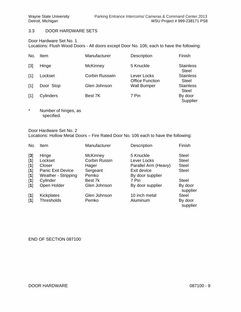
Wayne State University Parking Entrance Intercoms/ Cameras & Command Center 2013 Detroit, Michigan WSU Project # 999-238171 PS8
DOOR HARDWARE 087100 - 9
3.3 DOOR HARDWARE SETS
Door Hardware Set No. 1 Locations: Flush Wood Doors - All doors except Door No. 106; each to have the following:
No. Item Manufacturer Description Finish
[3] Hinge McKinney 5 Knuckle Stainless
Steel [1] Lockset Corbin Russwin Lever Locks
Office Function Stainless
Steel [1] Door Stop Glen Johnson Wall Bumper Stainless
Steel [1] Cylinders Best 7K 7 Pin By door
Supplier * Number of hinges, as
specified.
Door Hardware Set No. 2 Locations: Hollow Metal Doors – Fire Rated Door No. 106 each to have the following:
No. Item Manufacturer Description Finish
[3] Hinge McKinney 5 Knuckle Steel [1] Lockset Corbin Russin Lever Locks Steel [1] Closer Hager Parallel Arm (Heavy) Steel [1] Panic Exit Device Sergeant Exit device Steel [1] Weather - Stripping Pemko By door supplier [1] Cylinder Best 7k 7 Pin Steel [1] Open Holder Glen Johnson By door supplier By door
supplier [1] Kickplates Glen Johnson 10 inch metal Steel [1] Thresholds Pemko Aluminum By door
supplier
END OF SECTION 087100
Wayne State University Parking Entrance Intercoms/ Cameras & Command Center 2013 Detroit, Michigan WSU Project # 999-238171 PS8
GLAZING 088000 - 1
SECTION 088000 - GLAZING
PART 1 - GENERAL
1.1 SUMMARY
A. This Section includes glazing for the following products and applications, including those specified in other Sections where glazing requirements are specified by reference to this Section: 1. Windows. 2. Glass – in Hollow Metal doors. 3. Aluminum Storefront framing and entrances. 4. Glazing compounds and accessories. 5.
1.2 DEFINITIONS
A. Interspace: Space between lites of an insulating-glass unit that contains dehydrated air or a specified gas.
B. Deterioration of Coated Glass: Defects developed from normal use that are attributed to the manufacturing process and not to causes other than glass breakage and practices for maintaining and cleaning coated glass contrary to manufacturer's written instructions. Defects include peeling, cracking, and other indications of deterioration in metallic coating.
C. Deterioration of Insulating Glass: Failure of hermetic seal under normal use that is attributed to the manufacturing process and not to causes other than glass breakage and practices for maintaining and cleaning insulating glass contrary to manufacturer's written instructions. Evidence of failure is the obstruction of vision by dust, moisture, or film on interior surfaces of glass.
1.3 PERFORMANCE REQUIREMENTS
A. General: Provide glazing systems capable of withstanding normal thermal movement and wind and impact loads (where applicable) without failure, including loss or glass breakage attributable to the following: defective manufacture, fabrication, and installation; failure of sealants or gaskets to remain watertight and airtight; deterioration of glazing materials; or other defects in construction.
a. Specified Design Wind Loads: not less than wind loads applicable to Project as required by ASCE 7 "Minimum Design Loads for Buildings and Other Structures": Section 6.0 "Wind Loads."
b. Minimum Glass Thickness for Exterior Lites: Not less than 6.0 mm. c. Thickness of Tinted and Heat-Absorbing Glass: Provide the same
thickness for each tint color indicated throughout Project.

Wayne State University Parking Entrance Intercoms/ Cameras & Command Center 2013 Detroit, Michigan WSU Project # 999-238171 PS8
GLAZING 088000 - 2
B. Thermal Movements: Provide glazing that allows for thermal movements resulting from the following maximum change (range) in ambient and surface temperatures acting on glass framing members and glazing components. Base engineering calculation on surface temperatures of materials due to both solar heat gain and nighttime-sky heat loss.
C. Thermal and Optical Performance Properties: Provide glass with performance properties specified based on manufacturer's published test data, as determined according to procedures indicated below:
1. For monolithic-glass lites, properties are based on units with lites 6.0 mm thick. 2. For insulating-glass units, properties are based on units of thickness indicated for
overall unit and for each lite 6.0 mm thick and a nominal 1/2-inch- (12.7-mm-) wide interspace.
3. Center-of-Glass Values: Based on using LBL-44789 WINDOW 5.0 computer program for the following methodologies:
a. U-Factors: NFRC 100 expressed as Btu/ sq. ft. x h x deg F (W/sq. m x K). b. Solar Heat Gain Coefficient: NFRC 200. c. Solar Optical Properties: NFRC 300.
1.4 SUBMITTALS
A. Product Data: For each glass product and glazing material indicated.
B. Samples: 12-inch- (300-mm-) square, for each type of glass product indicated, other than monolithic clear float glass.
C. Glazing Schedule: Use same designations indicated on Drawings.
D. Preconstruction Adhesion and Compatibility Test Report: From glazing sealant manufacturer.
1.5 QUALITY ASSURANCE
A. Preconstruction Adhesion and Compatibility Testing: Submit to elastomeric glazing sealant manufacturers, for testing according to ASTM C 1087, samples of each glazing material type, tape sealant, gasket, glazing accessory, and glass-framing member that will contact or affect elastomeric glazing sealants:
B. Glazing for Fire-Rated Door Assemblies: Glazing for assemblies that comply with NFPA 80 and that are listed and labeled by a testing and inspecting agency acceptable to authorities having jurisdiction, for fire ratings indicated, based on testing according to NFPA 257.
C. Safety Glazing Products: Comply with testing requirements in 16 CFR 1201 and, for wired glass, ANSI Z97.1.

Wayne State University Parking Entrance Intercoms/ Cameras & Command Center 2013 Detroit, Michigan WSU Project # 999-238171 PS8
GLAZING 088000 - 3
D. Glazing Publications: Comply with published recommendations of glass product manufacturers and organizations below, unless more stringent requirements are indicated. Refer to these publications for glazing terms not otherwise defined in this Section or in referenced standards.
1. GANA Publications: GANA's "Glazing Manual." 2. IGMA Publication for Insulating Glass: SIGMA TM-3000, "Glazing Guidelines for
Sealed Insulating Glass Units."
E. Insulating-Glass Certification Program: Permanently marked either on spacers or on at least one component lite of units with appropriate certification label of the Insulating Glass Certification Council.
F. Mockups: Build mockups to verify selections made under sample submittals and to demonstrate aesthetic effects and set quality standards for materials and execution.
1. Build mockups as shown on Drawings. 2. Approved mockups may become part of the completed Work if undisturbed at
time of Substantial Completion.
1.6 WARRANTY
A. Manufacturer's Special Warranty for Coated-Glass Products: Manufacturer's standard form, made out to Owner and signed by coated-glass manufacturer agreeing to replace coated-glass units that deteriorate as defined in "Definitions" Article, f.o.b. the nearest shipping point to Project site, within specified warranty period indicated below.
B. Manufacturer's Special Warranty on Insulating Glass: Manufacturer's standard form, made out to Owner and signed by insulating-glass manufacturer agreeing to replace insulating-glass units that deteriorate as defined in "Definitions" Article, f.o.b. the nearest shipping point to Project site, within specified warranty period indicated below..
PART 2 - PRODUCTS
2.1 MANUFACTURERS
A. In other Part 2 articles where titles below introduce lists, the following requirements apply to product selection: 1. Manufacturers: Subject to compliance with requirements, provide products by
one of the manufacturers specified.
2.2 GLASS PRODUCTS
A. Annealed Float Glass: ASTM C 1036, Type I (transparent flat glass), Quality-Q3; of class indicated.
Wayne State University Parking Entrance Intercoms/ Cameras & Command Center 2013 Detroit, Michigan WSU Project # 999-238171 PS8
GLAZING 088000 - 4
1. Ultra-Clear (Low-Iron) Float Glass: Class I (clear); with a minimum 91 percent visible light transmission and a minimum solar heat gain coefficient of 0.87.
a. Products:
1) AFG Industries Inc.,
2) Ford Glass,
3) Guardian Industries Corp,
B. Wired Glass: ASTM C 1036, Type II (wired flat glass), Class 1 (clear), Quality-Q-6; and of form and mesh pattern specified.
C. Insulating-Glass Units, General: Factory-assembled units consisting of sealed lites of glass separated by a dehydrated interspace, and complying with ASTM E 774 for Class CBA units and with requirements specified in this Article and in Part 2 "Insulating-Glass Units" Article.
1. Provide Kind HS (heat-strengthened) float glass in place of annealed glass where needed to resist thermal stresses induced by differential shading of individual glass lites and to comply with glass design requirements specified in Part 1 "Performance Requirements" Article.
2. Overall Unit Thickness and Thickness of Each Lite: Dimensions indicated for insulating-glass units are nominal and the overall thicknesses of units are measured perpendicularly from outer surfaces of glass lites at unit's edge.
3. Sealing System: Dual seal. 4. Spacer Specifications: Manufacturer's standard spacer material and construction
complying with the following requirements:
a. Spacer Material: Aluminum with mill or clear anodic finish. b. Corner Construction: Manufacturer's standard corner construction.
2.3 MONOLITHIC-GLASS TYPES
A. Glass Type [GL-1]: Clear float glass. Tempered
1. Thickness: ¼ inch 2. Provide safety glazing labeling. 3. All glazing is to be float glass unless otherwise indicated.
B. Glass Type [GL-2]: Wired glass -flat glass, Class 1 (clear)
1. Thickness: ¼ inch 2. Provide safety glazing and fire rating labeling.
C. Glass Type [GL-3]: Insulating-Glass Units, General: Factory-assembled
1. Thickness: Per manufacturer 2. Provide safety glazing labeling per manufacturer.
Wayne State University Parking Entrance Intercoms/ Cameras & Command Center 2013 Detroit, Michigan WSU Project # 999-238171 PS8
GLAZING 088000 - 5
2.4 GLAZING GASKETS
A. Dense Compression Gaskets: Molded or extruded gaskets of material indicated below, complying with standards referenced with name of elastomer indicated below, and of profile and hardness required to maintain watertight seal:
1. Neoprene, ASTM C 864. 2. EPDM, ASTM C 864. 3. Silicone, ASTM C 1115. 4. Thermoplastic polyolefin rubber, ASTM C 1115. 5. Any material indicated above.
B. Soft Compression Gaskets: Extruded or molded, closed-cell, integral-skinned gaskets of material indicated below; complying with ASTM C 509, Type II, black; and of profile and hardness required to maintain watertight seal:
1. Neoprene. 2. EPDM. 3. Silicone. 4. Thermoplastic polyolefin rubber. 5. Any material indicated above.
2.5 GLAZING SEALANTS
A. General: Provide products of type indicated, complying with the following requirements:
1. Compatibility: Select glazing sealants that are compatible with one another and with other materials they will contact, including glass products, seals of insulating-glass units, and glazing channel substrates, under conditions of service and application, as demonstrated by sealant manufacturer based on testing and field experience.
2. Suitability: Comply with sealant and glass manufacturers' written instructions for selecting glazing sealants suitable for applications indicated and for conditions existing at time of installation.
3. VOC Content: For sealants used inside of the weatherproofing system, not more than 250 g/L when calculated according to 40 CFR 59, Subpart D (EPA Method 24).
4. Colors of Exposed Glazing Sealants: As selected by Architect from manufacturer's full range.
B. Glazing Sealants for Fire-Resistive Glazing Products: Identical to products used in test assemblies to obtain fire-protection rating.
2.6 GLAZING TAPES
A. Back-Bedding Mastic Glazing Tapes: Preformed, butyl-based elastomeric tape with a solids content of 100 percent; nonstaining and nonmigrating in contact with nonporous

Wayne State University Parking Entrance Intercoms/ Cameras & Command Center 2013 Detroit, Michigan WSU Project # 999-238171 PS8
GLAZING 088000 - 6
surfaces; with or without spacer rod as recommended in writing by tape and glass manufacturers for application indicated; packaged on rolls with a release paper backing; and complying with ASTM C 1281 and AAMA 800 for products indicated below:
B. Expanded Cellular Glazing Tapes: Closed-cell, PVC foam tapes; factory coated with adhesive on both surfaces; packaged on rolls with release liner protecting adhesive; and complying with AAMA 800 for the following types:
1. Type 1, for glazing applications in which tape acts as the primary sealant. 2. Type 2, for glazing applications in which tape is used in combination with a full
bead of liquid sealant.
2.7 MISCELLANEOUS GLAZING MATERIALS
A. General: Provide products of material, size, and shape complying with referenced glazing standard, requirements of manufacturers of glass and other glazing materials for application indicated, and with a proven record of compatibility with surfaces contacted in installation.
B. Cleaners, Primers, and Sealers: Types recommended by sealant or gasket manufacturer.
C. Setting Blocks: Elastomeric material with a Shore, Type A durometer hardness of 85, plus or minus 5.
D. Spacers: Elastomeric blocks or continuous extrusions with a Shore, Type A durometer hardness required by glass manufacturer to maintain glass lites in place for installation indicated.
E. Edge Blocks: Elastomeric material of hardness needed to limit glass lateral movement (side walking).
F. Cylindrical Glazing Sealant Backing: ASTM C 1330, Type O (open-cell material), of size and density to control glazing sealant depth and otherwise produce optimum glazing sealant performance.
G. Perimeter Insulation for Fire-Resistive Glazing: Identical to product used in test assembly to obtain fire-resistance rating.
2.8 FABRICATION OF GLAZING UNITS
A. Fabricate glazing units in sizes required to glaze openings indicated for Project, with edge and face clearances, edge and surface conditions, and bite complying with written instructions of product manufacturer and referenced glazing publications, to comply with system performance requirements.
Wayne State University Parking Entrance Intercoms/ Cameras & Command Center 2013 Detroit, Michigan WSU Project # 999-238171 PS8
GLAZING 088000 - 7
PART 3 - EXECUTION
3.1 GLAZING
A. General: Comply with combined written instructions of manufacturers of glass, sealants, gaskets, and other glazing materials, unless more stringent requirements are indicated, including those in referenced glazing publications.
1. Glazing channel dimensions, as indicated on Drawings, provide necessary bite on glass, minimum edge and face clearances, and adequate sealant thicknesses, with reasonable tolerances. Adjust as required by Project conditions during installation.
2. Protect glass edges from damage during handling and installation. Remove damaged glass from Project site and legally dispose of off Project site. Damaged glass is glass with edge damage or other imperfections that, when installed, could weaken glass and impair performance and appearance.
3. Apply primers to joint surfaces where required for adhesion of sealants, as determined by preconstruction sealant-substrate testing.
4. Install setting blocks in sill rabbets, sized and located to comply with referenced glazing publications, unless otherwise required by glass manufacturer. Set blocks in thin course of compatible sealant suitable for heel bead.
5. Do not exceed edge pressures stipulated by glass manufacturers for installing glass lites.
6. Provide spacers for glass lites where length plus width is larger than 50 inches (1270 mm).
7. Provide edge blocking where indicated or needed to prevent glass lites from moving sideways in glazing channel, as recommended in writing by glass manufacturer and according to requirements in referenced glazing publications.
3.2 CLEANING AND PROTECTION
A. Protect exterior glass from damage immediately after installation by attaching crossed streamers to framing held away from glass. Do not apply markers to glass surface. Remove nonpermanent labels, and clean surfaces. Protect glass from contact with contaminating substances resulting from construction operations, including weld splatter. If, despite such protection, contaminating substances do come into contact with glass, remove substances immediately as recommended by glass manufacturer.
B. Remove and replace glass that is broken, chipped, cracked, or abraded or that is damaged from natural causes, accidents, and vandalism, during construction period.
END OF SECTION 088000

Wayne State University Parking Entrance Intercoms/ Cameras & Command Center 2013 Detroit, Michigan WSU Project # 999-238171 PS8
LOUVERS AND VENTS 089000 - 1
SECTION 089000 - LOUVERS AND VENTS
PART 1 - GENERAL
1.1 SUMMARY
A. Section Includes:
1. Fixed, extruded-aluminum louvers.
B. See Division 23 Sections for louvers that are a part of mechanical equipment.
1.2 PERFORMANCE REQUIREMENTS
A. Structural Performance: Louvers shall withstand the effects of gravity loads and the following loads and stresses within limits and under conditions indicated without permanent deformation of louver components, noise or metal fatigue caused by louver blade rattle or flutter, or permanent damage to fasteners and anchors.
1. Wind Loads: Determine loads based on pressures as indicated on Drawings. 2. Wind Loads: Determine loads based on a uniform pressure of [20 lbf/sq. ft. (957
Pa)] [30 lbf/sq. ft. (1436 Pa)] <Insert design wind pressure>, acting inward or outward.
B. Louver Performance Ratings: Provide louvers complying with requirements specified, as demonstrated by testing manufacturer's stock units identical to those provided, except for length and width according to AMCA 500-L.
1.3 SUBMITTALS
A. Product Data: For each type of product indicated.
1. For louvers specified to bear AMCA seal, include printed catalog pages showing specified models with appropriate AMCA Certified Ratings Seals.
B. Shop Drawings: For louvers and accessories. Include plans, elevations, sections, details, and attachments to other work. Show frame profiles and blade profiles, angles, and spacing.
C. Samples: For each type of metal finish required.
D. Product Test Reports: Based on tests performed according to AMCA 500-L.
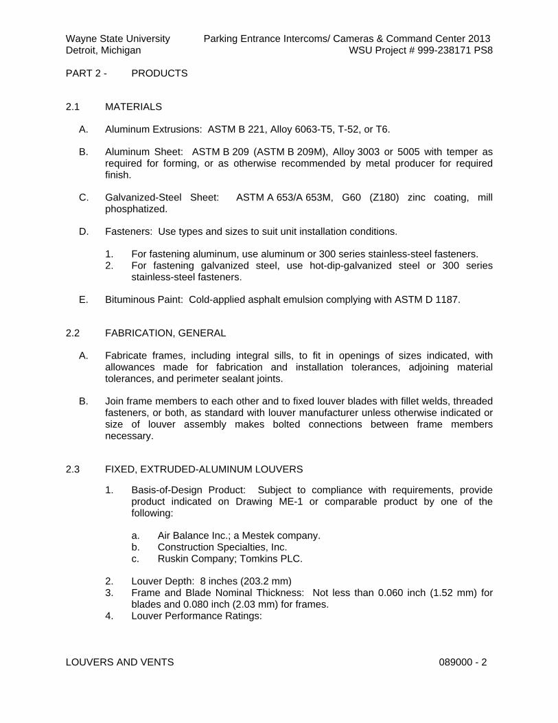
Wayne State University Parking Entrance Intercoms/ Cameras & Command Center 2013 Detroit, Michigan WSU Project # 999-238171 PS8
LOUVERS AND VENTS 089000 - 2
PART 2 - PRODUCTS
2.1 MATERIALS
A. Aluminum Extrusions: ASTM B 221, Alloy 6063-T5, T-52, or T6.
B. Aluminum Sheet: ASTM B 209 (ASTM B 209M), Alloy 3003 or 5005 with temper as required for forming, or as otherwise recommended by metal producer for required finish.
C. Galvanized-Steel Sheet: ASTM A 653/A 653M, G60 (Z180) zinc coating, mill phosphatized.
D. Fasteners: Use types and sizes to suit unit installation conditions.
1. For fastening aluminum, use aluminum or 300 series stainless-steel fasteners. 2. For fastening galvanized steel, use hot-dip-galvanized steel or 300 series
stainless-steel fasteners.
E. Bituminous Paint: Cold-applied asphalt emulsion complying with ASTM D 1187.
2.2 FABRICATION, GENERAL
A. Fabricate frames, including integral sills, to fit in openings of sizes indicated, with allowances made for fabrication and installation tolerances, adjoining material tolerances, and perimeter sealant joints.
B. Join frame members to each other and to fixed louver blades with fillet welds, threaded fasteners, or both, as standard with louver manufacturer unless otherwise indicated or size of louver assembly makes bolted connections between frame members necessary.
2.3 FIXED, EXTRUDED-ALUMINUM LOUVERS
1. Basis-of-Design Product: Subject to compliance with requirements, provide product indicated on Drawing ME-1 or comparable product by one of the following:
a. Air Balance Inc.; a Mestek company. b. Construction Specialties, Inc. c. Ruskin Company; Tomkins PLC.
2. Louver Depth: 8 inches (203.2 mm) 3. Frame and Blade Nominal Thickness: Not less than 0.060 inch (1.52 mm) for
blades and 0.080 inch (2.03 mm) for frames. 4. Louver Performance Ratings:

Wayne State University Parking Entrance Intercoms/ Cameras & Command Center 2013 Detroit, Michigan WSU Project # 999-238171 PS8
LOUVERS AND VENTS 089000 - 3
a. Free Area: Not less than 5.0 sq. ft. (0.46 sq. m) for 36-inch- wide by 12-inch- high louver.
b. Air Performance: Not more than [0.10-inch wg static pressure drop at 700-fpm free-area intake velocity.
5. AMCA Seal: Mark units with AMCA Certified Ratings Seal.
2.4 LOUVER SCREENS
A. General: Provide screen at each exterior louver.
B. Louver Screen Frames: Same kind and form of metal as indicated for louver to which screens are attached.
C. Louver Screening:
1. Bird Screening: Aluminum, 1/2-inch- (13-mm-) square mesh, 0.063-inch (1.60-mm) wire.
2.5 ALUMINUM FINISHES
A. Clear Anodize Finish: AAMA 611, AA-M12C22A41, Class I, 0.018 mm or thicker.
PART 3 - EXECUTION
3.1 INSTALLATION
A. Locate and place louvers and vents level, plumb, and at indicated alignment with adjacent work.
B. Use concealed anchorages where possible. Provide brass or lead washers fitted to screws where required to protect metal surfaces and to make a weathertight connection.
C. Provide perimeter reveals and openings of uniform width for sealants and joint fillers, as indicated.
D. Repair damaged finishes so no evidence remains of corrective work. Return items that cannot be refinished in the field to the factory and refinish entire unit or provide new units.
E. Protect galvanized and nonferrous-metal surfaces that will be in contact with concrete, masonry, or dissimilar metals from corrosion and galvanic action by applying a heavy coating of bituminous paint.

Wayne State University Parking Entrance Intercoms/ Cameras & Command Center 2013 Detroit, Michigan WSU Project # 999-238171 PS8
LOUVERS AND VENTS 089000 - 4
END OF SECTION 089000

Wayne State University Parking Entrance Intercoms/ Cameras & Command Center 2013 Detroit, Michigan WSU Project # 999-238171 PS8
NON-STRUCTURAL METAL FRAMING 092216 - 1
SECTION 092216 - NON-STRUCTURAL METAL FRAMING
PART 1 - GENERAL
1.1 SUMMARY
A. This Section includes non-load-bearing steel framing members for the following applications:
1. Interior framing systems (e.g., supports for partition walls, framed soffits, furring, etc.).
2. Interior suspension systems (e.g., supports for ceilings, suspended soffits, etc.).
1.2 SUBMITTALS
A. Product Data: For each type of product indicated.
1.3 QUALITY ASSURANCE
A. Fire-Test-Response Characteristics: For fire-resistance-rated assemblies that incorporate non-load-bearing steel framing, provide materials and construction identical to those tested in assembly indicated according to ASTM E 119 by an independent testing agency.
B. Sound Transmission Characteristics: For STC-rated assemblies that incorporate non-load-bearing steel framing, provide materials and construction identical to those tested in assembly indicated according to ASTM E 90 and classified according to ASTM E 413 by an independent testing agency.
PART 2 - PRODUCTS
2.1 NON-LOAD-BEARING STEEL FRAMING, GENERAL
A. Framing Members, General: Comply with ASTM C 754 for conditions indicated.
1. Steel Sheet Components: Comply with ASTM C 645 requirements for metal, unless otherwise indicated.
2. Protective Coating: Manufacturer's standard corrosion-resistant zinc coating, unless otherwise indicated.
2.2 STEEL FRAMING FOR FRAMED ASSEMBLIES
A. Steel Studs and Runners: ASTM C 645.

Wayne State University Parking Entrance Intercoms/ Cameras & Command Center 2013 Detroit, Michigan WSU Project # 999-238171 PS8
NON-STRUCTURAL METAL FRAMING 092216 - 2
1. Minimum Base-Metal Thickness: 0.027 inch (0.7 mm)
B. Slip-Type Head Joints: Where indicated, provide one of the following:
1. Single Long-Leg Runner System: ASTM C 645 top runner with 2-inch- (50.8-mm-) deep flanges in thickness not less than indicated for studs, installed with studs friction fit into top runner and with continuous bridging located within 12 inches (305 mm) of the top of studs to provide lateral bracing.
2. Double-Runner System: ASTM C 645 top runners, inside runner with 2-inch- (50.8-mm-) deep flanges in thickness not less than indicated for studs and fastened to studs, and outer runner sized to friction fit inside runner.
3. Deflection Track: Steel sheet top runner manufactured to prevent cracking of finishes applied to interior partition framing resulting from deflection of structure above; in thickness not less than indicated for studs and in width to accommodate depth of studs.
a. Available Products: Subject to compliance with requirements, products that may be incorporated into the Work include, but are not limited to, the following:
1) Steel Network Inc. (The); VertiClip SLD Series. 2) Superior Metal Trim; Superior Flex Track System (SFT). 3) Grace Construction Products
C. Flat Strap and Backing Plate: Steel sheet for blocking and bracing in length and width indicated.
1. Minimum Base-Metal Thickness: 0.0179 inch (0.45 mm).
D. Z-Shaped Furring: With slotted or nonslotted web, face flange of 1-1/4 inches (31.8 mm), wall attachment flange of 7/8 inch (22.2 mm), minimum bare-metal thickness of 0.0179 inch (0.45 mm), and depth required to fit insulation thickness indicated.
2.3 AUXILIARY MATERIALS
A. Fasteners for Metal Framing: Of type, material, size, corrosion resistance, holding power, and other properties required to fasten steel members to substrates.
B. Isolation Strip at Exterior Walls: Provide one of the following:
1. Asphalt-Saturated Organic Felt: ASTM D 226, Type I (No. 15 asphalt felt), nonperforated.
2. Foam Gasket: Adhesive-backed, closed-cell vinyl foam strips that allow fastener penetration without foam displacement, 1/8 inch (3.2 mm) thick, in width to suit steel stud size.
C. Diamond-Mesh Lath:

Wayne State University Parking Entrance Intercoms/ Cameras & Command Center 2013 Detroit, Michigan WSU Project # 999-238171 PS8
NON-STRUCTURAL METAL FRAMING 092216 - 3
1. Metal lath – flat (without backing paper). G 60 Galvanized Steel. Weight: 2.5lb/sq.yd (1.4 kg/sq m). Secured to metal studs at gypsum board partition wall type ‘B’ on construction drawings. Metal lath installation to start where gypsum board terminates above finished ceiling and extend to stud deflection track.
2. Manufactures: One of the following:
a. Clark Dietrich
b. Flannery, Inc.
c. Cemco
PART 3 - EXECUTION
3.1 INSTALLATION, GENERAL
A. Installation Standard: ASTM C 754.
1. Gypsum Board Assemblies: Also comply with requirements in ASTM C 840 that apply to framing installation.
3.2 INSTALLING FRAMED ASSEMBLIES
A. Where studs are installed directly against exterior masonry walls or dissimilar metals at exterior walls, install isolation strip between studs and exterior wall.
B. Install tracks (runners) at floors and overhead supports. Extend framing full height to structural supports or substrates above suspended ceilings, except where partitions are indicated to terminate at suspended ceilings. Continue framing around ducts penetrating partitions above ceiling.
1. Slip-Type Head Joints: Where framing extends to overhead structural supports, install to produce joints at tops of framing systems that prevent axial loading of finished assemblies.
2. Door Openings: Screw vertical studs at jambs to jamb anchor clips on door frames; install runner track section (for cripple studs) at head and secure to jamb studs.
a. Install two studs at each jamb, unless otherwise indicated. b. Install cripple studs at head adjacent to each jamb stud, with a minimum
1/2-inch (12.7-mm) clearance from jamb stud to allow for installation of control joint in finished assembly.
c. Extend jamb studs through suspended ceilings and attach to underside of overhead structure.

Wayne State University Parking Entrance Intercoms/ Cameras & Command Center 2013 Detroit, Michigan WSU Project # 999-238171 PS8
NON-STRUCTURAL METAL FRAMING 092216 - 4
3. Other Framed Openings: Frame openings other than door openings the same as required for door openings, unless otherwise indicated. Install framing below sills of openings to match framing required above door heads.
4. Sound-Rated Partitions: Install framing to comply with sound-rated assembly indicated.
C. Z-Furring Members:
1. Erect insulation (specified in Division 07 Section "Thermal Insulation") vertically and hold in place with Z-furring members spaced 24 inches (610 mm) o.c.
2. Except at exterior corners, securely attach narrow flanges of furring members to wall with concrete stub nails, screws designed for masonry attachment, or powder-driven fasteners spaced 24 inches (600 mm) o.c.
3. At exterior corners, attach wide flange of furring members to wall with short flange extending beyond corner; on adjacent wall surface, screw-attach short flange of furring channel to web of attached channel. At interior corners, space second member no more than 12 inches (300 mm) from corner and cut insulation to fit.
D. Installation Tolerance: Install each framing member so fastening surfaces vary not more than 1/8 inch (3 mm) from the plane formed by faces of adjacent framing.
END OF SECTION 092216

Wayne State University Parking Entrance Intercoms/ Cameras & Command Center 2013 Detroit, Michigan WSU Project # 999-238171 PS8
GYPSUM BOARD 092900 - 1
SECTION 092900 - GYPSUM BOARD
PART 1 - GENERAL
1.1 SUMMARY
A. This Section includes the following:
1. Interior gypsum board. 2. Interior gypsum board for ceiling and soffits.
1.2 SUBMITTALS
A. Product Data: For each type of product indicated.
1.3 QUALITY ASSURANCE
A. Fire-Resistance-Rated Assemblies: For fire-resistance-rated assemblies, provide materials and construction identical to those tested in assembly indicated according to ASTM E 119 by an independent testing agency.
B. STC-Rated Assemblies: For STC-rated assemblies, provide materials and construction identical to those tested in assembly indicated according to ASTM E 90 and classified according to ASTM E 413 by an independent testing agency.
PART 2 - PRODUCTS
2.1 INTERIOR GYPSUM BOARD
A. General: Complying with ASTM C 36/C 36M or ASTM C 1396/C 1396M, as applicable to type of gypsum board indicated and whichever is more stringent.
1. Available Manufacturers: Subject to compliance with requirements, manufacturers offering products that may be incorporated into the Work include, but are not limited to, the following:
a. American Gypsum Co. b. BPB America Inc. c. G-P Gypsum. d. Lafarge North America Inc. e. National Gypsum Company. f. USG Corporation.
B. Type X:
1. Thickness: 5/8 inch (15.9 mm).
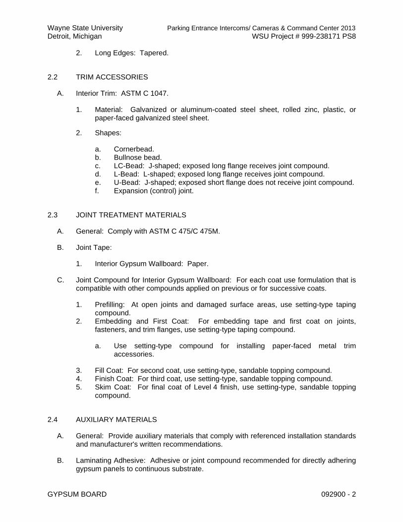
Wayne State University Parking Entrance Intercoms/ Cameras & Command Center 2013 Detroit, Michigan WSU Project # 999-238171 PS8
GYPSUM BOARD 092900 - 2
2. Long Edges: Tapered.
2.2 TRIM ACCESSORIES
A. Interior Trim: ASTM C 1047.
1. Material: Galvanized or aluminum-coated steel sheet, rolled zinc, plastic, or paper-faced galvanized steel sheet.
2. Shapes:
a. Cornerbead. b. Bullnose bead. c. LC-Bead: J-shaped; exposed long flange receives joint compound. d. L-Bead: L-shaped; exposed long flange receives joint compound. e. U-Bead: J-shaped; exposed short flange does not receive joint compound. f. Expansion (control) joint.
2.3 JOINT TREATMENT MATERIALS
A. General: Comply with ASTM C 475/C 475M.
B. Joint Tape:
1. Interior Gypsum Wallboard: Paper.
C. Joint Compound for Interior Gypsum Wallboard: For each coat use formulation that is compatible with other compounds applied on previous or for successive coats.
1. Prefilling: At open joints and damaged surface areas, use setting-type taping compound.
2. Embedding and First Coat: For embedding tape and first coat on joints, fasteners, and trim flanges, use setting-type taping compound.
a. Use setting-type compound for installing paper-faced metal trim accessories.
3. Fill Coat: For second coat, use setting-type, sandable topping compound. 4. Finish Coat: For third coat, use setting-type, sandable topping compound. 5. Skim Coat: For final coat of Level 4 finish, use setting-type, sandable topping
compound.
2.4 AUXILIARY MATERIALS
A. General: Provide auxiliary materials that comply with referenced installation standards and manufacturer's written recommendations.
B. Laminating Adhesive: Adhesive or joint compound recommended for directly adhering gypsum panels to continuous substrate.

Wayne State University Parking Entrance Intercoms/ Cameras & Command Center 2013 Detroit, Michigan WSU Project # 999-238171 PS8
GYPSUM BOARD 092900 - 3
1. Use adhesives that have a VOC content of 50 g/L or less when calculated according to 40 CFR 59, Subpart D (EPA Method 24).
C. Steel Drill Screws: ASTM C 1002, unless otherwise indicated.
1. Use screws complying with ASTM C 954 for fastening panels to steel members from 0.033 to 0.112 inch (0.84 to 2.84 mm) thick.
2. For fastening cementitious backer units, use screws of type and size recommended by panel manufacturer.
D. Sound Attenuation Blankets: ASTM C 665, Type I (blankets without membrane facing) produced by combining thermosetting resins with mineral fibers manufactured from glass, slag wool, or rock wool.
E. Acoustical Sealant: As specified in Division 07 Section "Joint Sealants."
1. Provide sealants that have a VOC content of 250 g/L or less when calculated according to 40 CFR 59, Subpart D (EPA Method 24).
F. Thermal Insulation: As specified in Division 07 Section "Thermal Insulation."
G. Vapor Retarder: As specified in Division 07 Section "Thermal Insulation."
PART 3 - EXECUTION
3.1 APPLYING AND FINISHING PANELS, GENERAL
A. Comply with ASTM C 840.
B. Examine panels before installation. Reject panels that are wet, moisture damaged, and mold damaged.
C. Isolate perimeter of gypsum board applied to non-load-bearing partitions at structural abutments, except floors. Provide 1/4- to 1/2-inch- (6.4- to 12.7-mm-) wide spaces at these locations, and trim edges with edge trim where edges of panels are exposed. Seal joints between edges and abutting structural surfaces with acoustical sealant.
3.2 APPLYING INTERIOR GYPSUM BOARD
A. Install interior gypsum board in the following locations:
1. Type X: As indicated on Drawings.
3.3 INSTALLING TRIM ACCESSORIES
A. General: For trim with back flanges intended for fasteners, attach to framing with same fasteners used for panels. Otherwise, attach trim according to manufacturer's written instructions.

Wayne State University Parking Entrance Intercoms/ Cameras & Command Center 2013 Detroit, Michigan WSU Project # 999-238171 PS8
GYPSUM BOARD 092900 - 4
B. Control Joints: Install control joints at locations indicated on Drawings.
C. Interior Trim: Install in the following locations:
1. Cornerbead: Use at outside corners 2. Bullnose Bead: Use at outside corners. 3. LC-Bead: Use at exposed panel edges. 4. L-Bead: Use where indicated. 5. U-Bead: Use at exposed panel edges.
3.4 FINISHING GYPSUM BOARD
A. General: Treat gypsum board joints, interior angles, edge trim, control joints, penetrations, fastener heads, surface defects, and elsewhere as required to prepare gypsum board surfaces for decoration. Promptly remove residual joint compound from adjacent surfaces.
B. Prefill open joints, rounded or beveled edges, and damaged surface areas.
C. Apply joint tape over gypsum board joints, except those with trim having flanges not intended for tape.
D. Gypsum Board Finish Levels: Finish panels to levels indicated below:
1. Level 1: Ceiling plenum areas, concealed areas, and where indicated. 2. Level 4: At panel surfaces that will be exposed to view, unless otherwise
indicated.
a. Primer and its application to surfaces are specified in other Division 09 Sections.
3.5 PROTECTION
A. Protect installed products from damage from weather, condensation, direct sunlight, construction, and other causes during remainder of the construction period.
B. Remove and replace panels that are wet, moisture damaged, and mold damaged.
1. Indications that panels are wet or moisture damaged include, but are not limited to, discoloration, sagging, or irregular shape.
2. Indications that panels are mold damaged include, but are not limited to, fuzzy or splotchy surface contamination and discoloration.
END OF SECTION 092900

Wayne State University Parking Entrance Intercoms/ Cameras & Command Center 2013 Detroit, Michigan WSU Project # 999-238171 PS8
ACOUSTICAL TILE CEILINGS 095123 - 1
SECTION 095123 - ACOUSTICAL TILE CEILINGS
PART 1 - GENERAL
1.1 SUMMARY
A. This Section includes acoustical tiles and concealed suspension systems for ceilings.
1.2 SUBMITTALS
A. Product Data: For each type of product indicated.
B. Coordination Drawings: Drawn to scale and coordinating acoustical tile ceiling installation with hanger attachment to building structure and ceiling mounted items. Show size and location of initial access modules.
C. Samples: For each exposed finish.
D. Product test reports.
E. Research/evaluation reports.
F. Maintenance data.
1.3 QUALITY ASSURANCE
A. Acoustical Testing Agency Qualifications: An independent testing laboratory, or an NVLAP-accredited laboratory.
B. Fire-Test-Response Characteristics:
1. Fire-Resistance Characteristics: Where indicated, provide acoustical tile ceilings identical to those of assemblies tested for fire resistance per ASTM E 119 by UL or another testing and inspecting agency acceptable to authorities having jurisdiction.
a. Identify materials with appropriate markings of applicable testing and inspecting agency.
2. Surface-Burning Characteristics: Acoustical tiles complying with ASTM E 1264 for Class A materials, when tested per ASTM E 84.
a. Smoke-Developed Index: 450 or less.

Wayne State University Parking Entrance Intercoms/ Cameras & Command Center 2013 Detroit, Michigan WSU Project # 999-238171 PS8
ACOUSTICAL TILE CEILINGS 095123 - 2
PART 2 - PRODUCTS
2.1 ACOUSTICAL TILE CEILINGS, GENERAL
A. Acoustical Tile Standard: Comply with ASTM E 1264.
B. Acoustical Tile – High Sound Absorption
C. Metal Suspension System Standard: Comply with ASTM C 635.
D. Attachment Devices: Size for five times the design load indicated in ASTM C 635, Table 1, "Direct Hung," unless otherwise indicated. Comply with seismic design requirements.
1. Anchors in Concrete: Expansion anchors fabricated from corrosion-resistant materials, with holes or loops for attaching hangers of type indicated and with capability to sustain, without failure, a load equal to five times that imposed by ceiling construction, as determined by testing per ASTM E 488 or ASTM E 1512 as applicable, conducted by a qualified testing and inspecting agency.
2. Power-Actuated Fasteners in Concrete: Fastener system of type suitable for application indicated, fabricated from corrosion-resistant materials, with clips or other accessory devices for attaching hangers of type indicated, and with capability to sustain, without failure, a load equal to 10 times that imposed by ceiling construction, as determined by testing per ASTM E 1190, conducted by a qualified testing and inspecting agency.
E. Wire Hangers, Braces, and Ties: Zinc-coated carbon-steel wire; ASTM A 641/A 641M, Class 1 zinc coating, soft temper.
1. Size: Select wire diameter so its stress at 3 times hanger design load (ASTM C 635, Table 1, "Direct Hung") will be less than yield stress of wire, but provide not less than 0.106-inch- (2.69-mm-) diameter wire.
F. Metal Edge Moldings and Trim: Type and profile indicated or, if not indicated, manufacturer's standard moldings for edges and penetrations that comply with seismic design requirements; formed from sheet metal of same material, finish, and color as that used for exposed flanges of suspension system runners.
2.2 ACOUSTICAL TILES FOR ACOUSTICAL TILE CEILING
A. Available Products: Subject to compliance with requirements, products that may be incorporated into the Work include, but are not limited to, the following:
1. Armstrong World Industries, Inc. – Ultima 2. USG Interiors, Inc. – 3. Celotex Building Products
B. Classification: Provide fire-resistance-rated tiles complying with ASTM E 1264 for type and form as follows:
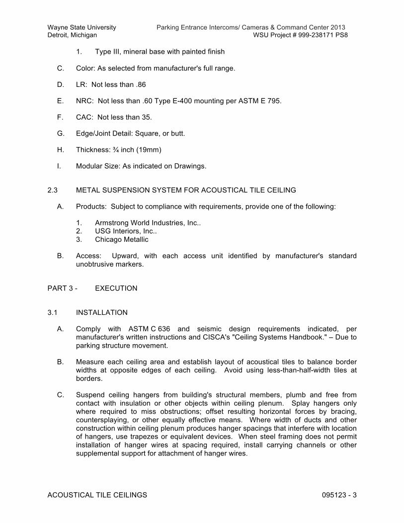
Wayne State University Parking Entrance Intercoms/ Cameras & Command Center 2013 Detroit, Michigan WSU Project # 999-238171 PS8
ACOUSTICAL TILE CEILINGS 095123 - 3
1. Type III, mineral base with painted finish
C. Color: As selected from manufacturer's full range.
D. LR: Not less than .86
E. NRC: Not less than .60 Type E-400 mounting per ASTM E 795.
F. CAC: Not less than 35.
G. Edge/Joint Detail: Square, or butt.
H. Thickness: ¾ inch (19mm)
I. Modular Size: As indicated on Drawings.
2.3 METAL SUSPENSION SYSTEM FOR ACOUSTICAL TILE CEILING
A. Products: Subject to compliance with requirements, provide one of the following:
1. Armstrong World Industries, Inc.. 2. USG Interiors, Inc.. 3. Chicago Metallic
B. Access: Upward, with each access unit identified by manufacturer's standard unobtrusive markers.
PART 3 - EXECUTION
3.1 INSTALLATION
A. Comply with ASTM C 636 and seismic design requirements indicated, per manufacturer's written instructions and CISCA's "Ceiling Systems Handbook." – Due to parking structure movement.
B. Measure each ceiling area and establish layout of acoustical tiles to balance border widths at opposite edges of each ceiling. Avoid using less-than-half-width tiles at borders.
C. Suspend ceiling hangers from building's structural members, plumb and free from contact with insulation or other objects within ceiling plenum. Splay hangers only where required to miss obstructions; offset resulting horizontal forces by bracing, countersplaying, or other equally effective means. Where width of ducts and other construction within ceiling plenum produces hanger spacings that interfere with location of hangers, use trapezes or equivalent devices. When steel framing does not permit installation of hanger wires at spacing required, install carrying channels or other supplemental support for attachment of hanger wires.

Wayne State University Parking Entrance Intercoms/ Cameras & Command Center 2013 Detroit, Michigan WSU Project # 999-238171 PS8
ACOUSTICAL TILE CEILINGS 095123 - 4
1. Do not support ceilings directly from floor deck; or anchor into concrete parking slabs.
D. Install edge moldings and trim of type indicated at perimeter of acoustical tile ceiling area and where necessary to conceal edges of acoustical tiles. Screw attach moldings to substrate at intervals not more than 16 inches (400 mm) o.c. and not more than 3 inches (75 mm) from ends, leveling with ceiling suspension system to a tolerance of 1/8 inch in 12 feet (3.2 mm in 3.6 m). Miter corners accurately and connect securely.
E. Install suspension system runners so they are square and securely interlocked with one another. Remove and replace dented, bent, or kinked members.
F. Install acoustical tiles in coordination with suspension system and exposed moldings and trim. Place splines or suspension system flanges into kerfed edges so tile-to-tile joints are closed by double lap of material.
END OF SECTION 095123

Wayne State University Parking Entrance Intercoms/ Cameras & Command Center 2013 Detroit, Michigan WSU Project # 999-238171 PS8
RESILIENT BASE AND ACCESSORIES 096513 - 1
SECTION 096513 - RESILIENT BASE AND ACCESSORIES
PART 1 - GENERAL
1.1 RELATED DOCUMENTS
A. Drawings, Wayne State University Construction Design Standards Sept. 2012, and general provisions of the Contract, including General and Supplementary Conditions and other Division 01 Specifications Sections, apply to this Section.
1.2 SUMMARY
A. Section Includes the following:
1. Resilient wall base and accessories.
1.3 SUBMITTALS
A. Product Data: For each type of product indicated.
B. Samples: For each type of product indicated, in manufacturer's standard-size Samples but not less than 12 inches (300 mm) long, of each resilient product color, texture, and pattern required.
1.4 QUALITY ASSURANCE
A. Fire-Test-Response Characteristics: As determined by testing identical products according to ASTM E 648 or NFPA 253 by a qualified testing agency.
1. Critical Radiant Flux Classification: Class I, not less than 0.45 W/sq. cm.
1.5 PROJECT CONDITIONS
A. Maintain ambient temperatures within range recommended by manufacturer in spaces to receive resilient products.
B. Until Substantial Completion, maintain ambient temperatures within range recommended by manufacturer.
C. Install resilient products after other finishing operations, including painting, have been completed.

Wayne State University Parking Entrance Intercoms/ Cameras & Command Center 2013 Detroit, Michigan WSU Project # 999-238171 PS8
RESILIENT BASE AND ACCESSORIES 096513 - 2
PART 2 - PRODUCTS
2.1 RESILIENT BASE
A. Resilient Base:
1. Manufacturers: Basis of Design – Material information and Selection. Refer to Schedule located in the Architects Drawings.
a. Armstrong World Industries, Inc.
B. Resilient Base Standard: ASTM F 1861.
C. Minimum Thickness: Min. 0.080 inch (2.0 mm).
D. Height: 4 inches (102 mm), As indicated on Drawings.
E. Lengths: Coils in manufacturer's standard length.
F. Corners (inside and outside): Provide prefabricated untis matching base in color and finish. Required at all bullnosed corners.
G. Finish: As selected by Architect from full range of industry colors.
H. Colors and Patterns: Intergrated 54 Black-Brown.
2.2 INSTALLATION MATERIALS
A. Trowelable Leveling and Patching Compounds: Latex-modified, portland cement based or blended hydraulic-cement-based formulation provided or approved by manufacturer for applications indicated.
B. Adhesives: Water-resistant type recommended by manufacturer to suit resilient products and substrate conditions indicated.
1. Use adhesives that comply with the following limits for VOC content when calculated according to 40 CFR 59, Subpart D (EPA Method 24):
a. Cove Base Adhesives: Not more than 50 g/L.
PART 3 - EXECUTION
3.1 PREPARATION
A. Prepare substrates according to manufacturer's written instructions to ensure adhesion of resilient products.

Wayne State University Parking Entrance Intercoms/ Cameras & Command Center 2013 Detroit, Michigan WSU Project # 999-238171 PS8
RESILIENT BASE AND ACCESSORIES 096513 - 3
B. Fill cracks, holes, and depressions in substrates with trowelable leveling and patching compound and remove bumps and ridges to produce a uniform and smooth substrate.
C. Do not install resilient products until they are same temperature as the space where they are to be installed.
1. Move resilient products and installation materials into spaces where they will be installed at least 48 hours in advance of installation.
D. Sweep and vacuum clean substrates to be covered by resilient products immediately before installation.
3.2 RESILIENT BASE INSTALLATION
A. Comply with manufacturer's written instructions for installing resilient base.
B. Apply resilient base to walls, columns, pilasters, casework and cabinets in toe spaces, and other permanent fixtures in rooms and areas where base is required.
C. Install resilient base in lengths as long as practicable without gaps at seams and with tops of adjacent pieces aligned.
D. Tightly adhere resilient base to substrate throughout length of each piece, with base in continuous contact with horizontal and vertical substrates.
E. Do not stretch resilient base during installation.
F. On masonry surfaces or other irregular substrate, fill void along top edge of wall base with manufacture’s recommended adhesives filler material.
G. Premolded Corners: Install premolded corners before installing straight pieces.
H. Outside Corners: Use straight pieces of maximum lengths possible. Form without producing discoloration (whitening) at bends. Shave back of base at points where bends occur and remove strips perpendicular to length of base that are only deep enough to produce a snug fit without removing more than half the wall base thickness.
F. Inside Corners: Use straight pieces of maximum lengths possible. Form by cutting an inverted V-shaped notch in toe of wall base at the point where corner is formed. Shave back of base where necessary to produce a snug fit to substrate.
1.1 CLEANING AND PROTECTION
A. Comply with manufacturer's written instructions for cleaning and protection of resilient products.
B. Cover resilient products until Substantial Completion.
END OF SECTION 096513

Wayne State University Parking Entrance Intercoms/ Cameras & Command Center 2013 Detroit, Michigan WSU Project # 999-238171 PS8
TILE CARPETING 096813 - 1
SECTION 096813 - TILE CARPETING
PART 1 - GENERAL
1.1 SUMMARY
A. This Section includes modular, carpet tile.
1.2 SUBMITTALS
A. Product Data: For each product indicated.
B. Shop Drawings: Show the following:
1. Existing flooring materials to be removed. 2. Existing flooring materials to remain. 3. Carpet tile type, color, and dye lot. 4. Pattern of installation. 5. Insets and borders. 6. Edge, transition, and other accessory strips. 7. Transition details to other flooring materials.
C. Samples: For each color and texture required.
1. Carpet Tile: Full-size Sample.
D. Product Schedule: For carpet tile. Use same designations indicated on Drawings.
E. Maintenance data.
1.3 QUALITY ASSURANCE
A. Installer Qualifications: An experienced installer who is certified by the Floor Covering Installation Board or who can demonstrate compliance with its certification program requirements.
B. Mockups: Before installing carpet tile, build mockups to verify selections made under sample submittals and to demonstrate aesthetic effects and set quality standards for materials and execution.
1.4 DELIVERY, STORAGE, AND HANDLING
A. Comply with CRI 104, Section 5, "Storage and Handling."
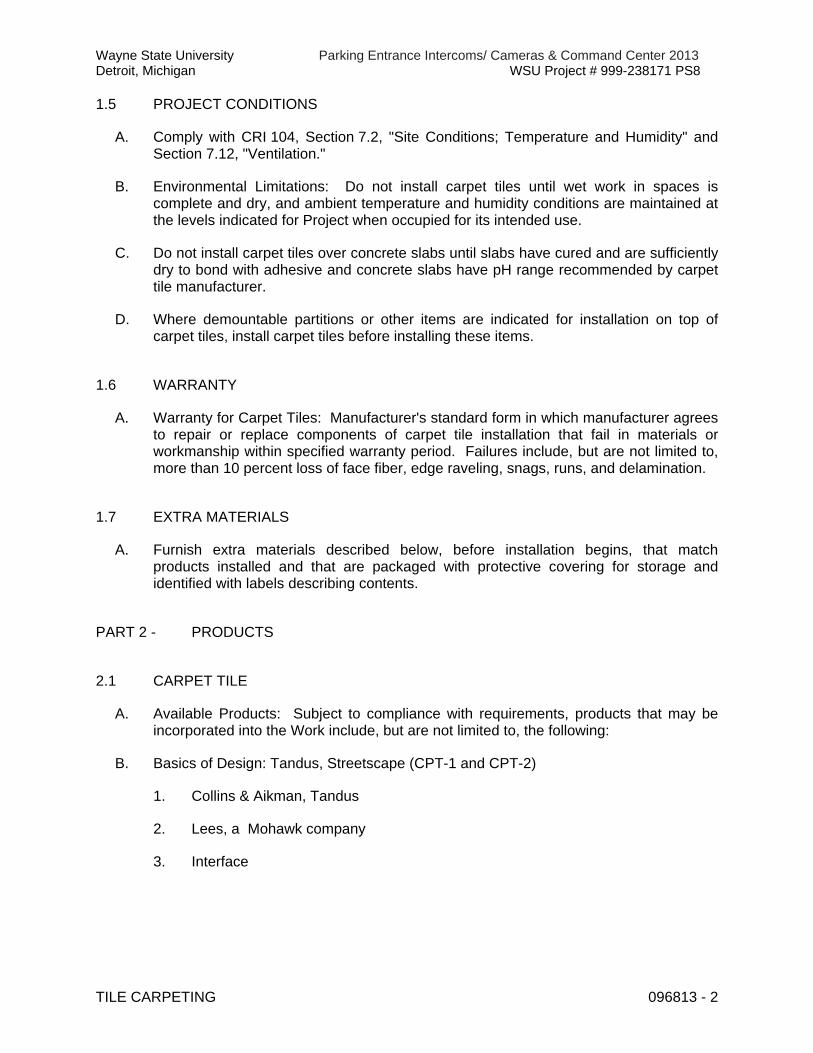
Wayne State University Parking Entrance Intercoms/ Cameras & Command Center 2013 Detroit, Michigan WSU Project # 999-238171 PS8
TILE CARPETING 096813 - 2
1.5 PROJECT CONDITIONS
A. Comply with CRI 104, Section 7.2, "Site Conditions; Temperature and Humidity" and Section 7.12, "Ventilation."
B. Environmental Limitations: Do not install carpet tiles until wet work in spaces is complete and dry, and ambient temperature and humidity conditions are maintained at the levels indicated for Project when occupied for its intended use.
C. Do not install carpet tiles over concrete slabs until slabs have cured and are sufficiently dry to bond with adhesive and concrete slabs have pH range recommended by carpet tile manufacturer.
D. Where demountable partitions or other items are indicated for installation on top of carpet tiles, install carpet tiles before installing these items.
1.6 WARRANTY
A. Warranty for Carpet Tiles: Manufacturer's standard form in which manufacturer agrees to repair or replace components of carpet tile installation that fail in materials or workmanship within specified warranty period. Failures include, but are not limited to, more than 10 percent loss of face fiber, edge raveling, snags, runs, and delamination.
1.7 EXTRA MATERIALS
A. Furnish extra materials described below, before installation begins, that match products installed and that are packaged with protective covering for storage and identified with labels describing contents.
PART 2 - PRODUCTS
2.1 CARPET TILE
A. Available Products: Subject to compliance with requirements, products that may be incorporated into the Work include, but are not limited to, the following:
B. Basics of Design: Tandus, Streetscape (CPT-1 and CPT-2)
1. Collins & Aikman, Tandus
2. Lees, a Mohawk company
3. Interface

Wayne State University Parking Entrance Intercoms/ Cameras & Command Center 2013 Detroit, Michigan WSU Project # 999-238171 PS8
TILE CARPETING 096813 - 3
2.2 INSTALLATION ACCESSORIES
A. Trowelable Leveling and Patching Compounds: Latex-modified, hydraulic-cement-based formulation provided or recommended by carpet tile manufacturer.
B. Adhesives: Water-resistant, mildew-resistant, nonstaining, pressure-sensitive type to suit products and subfloor conditions indicated, that complies with flammability requirements for installed carpet tile and is recommended by carpet tile manufacturer for releasable installation.
1. VOC Limits: Provide adhesives with VOC content not more than 50 g/L when calculated according to 40 CFR 59, Subpart D (EPA method 24).
PART 3 - EXECUTION
3.1 INSTALLATION
A. General: Comply with CRI 104, Section 14, "Carpet Modules," and with carpet tile manufacturer's written installation instructions.
B. Installation Method: As recommended in writing by carpet tile manufacturer.
C. Extend carpet tile into toe spaces, door reveals, closets, open-bottomed obstructions, removable flanges, alcoves, and similar openings.
D. Install pattern parallel to walls and borders.
END OF SECTION 096813

Wayne State University Parking Entrance Intercoms/ Cameras & Command Center 2013 Detroit, Michigan WSU Project # 999-238171 PS8
INTERIOR PAINTING 099123 - 1
SECTION 099123 - INTERIOR PAINTING
PART 1 - GENERAL
1.1 SUMMARY
A. This Section includes surface preparation and the application of paint systems on the following interior substrates:
1. Concrete masonry units (CMU). 2. Steel. 3. Gypsum board.
1.2 SUBMITTALS
A. Product Data: For each type of product indicated.
B. Samples: For each finish and for each color and texture required.
C. Product List: Printout of current "MPI Approved Products List" for each product category specified in Part 2, with the proposed product highlighted.
1.3 QUALITY ASSURANCE
A. MPI Standards:
1. Products: Complying with MPI standards indicated and listed in "MPI Approved Products List."
2. Preparation and Workmanship: Comply with requirements in "MPI Architectural Painting Specification Manual" for products and paint systems indicated.
1.4 EXTRA MATERIALS
A. Furnish extra materials described below that are from same production run (batch mix) as materials applied and that are packaged for storage and identified with labels describing contents.
PART 2 - PRODUCTS
2.1 PAINT, GENERAL
A. Material Compatibility:

Wayne State University Parking Entrance Intercoms/ Cameras & Command Center 2013 Detroit, Michigan WSU Project # 999-238171 PS8
INTERIOR PAINTING 099123 - 2
1. Provide materials for use within each paint system that are compatible with one another and substrates indicated, under conditions of service and application as demonstrated by manufacturer, based on testing and field experience.
2. For each coat in a paint system, provide products recommended in writing by manufacturers of topcoat for use in paint system and on substrate indicated.
B. VOC Content of Field-Applied Interior Paints and Coatings: Provide products that comply with the following limits for VOC content, exclusive of colorants added to a tint base, when calculated according to 40 CFR 59, Subpart D (EPA Method 24); these requirements do not apply to paints and coatings that are applied in a fabrication or finishing shop:
2.2 BLOCK FILLERS
A. Interior/Exterior Latex Block Filler: MPI #4.
2.3 PRIMERS/SEALERS
A. Interior Latex Primer/Sealer: MPI #50.
2.4 METAL PRIMERS
A. Rust-Inhibitive Primer (Water Based): MPI #107.
1. VOC Content: Low VOC
2.5 LATEX PAINTS
A. Interior Latex (Eggshell): MPI #52 (Gloss Level 3).
1. VOC Content: Low VOC
B. Interior Latex (Semigloss): MPI #54 (Gloss Level 4).
1. VOC Content: Low VOC
PART 3 - EXECUTION
3.1 EXAMINATION
A. Examine substrates and conditions, with Applicator present, for compliance with requirements for maximum moisture content and other conditions affecting performance of work.
B. Maximum Moisture Content of Substrates: When measured with an electronic moisture meter as follows:

Wayne State University Parking Entrance Intercoms/ Cameras & Command Center 2013 Detroit, Michigan WSU Project # 999-238171 PS8
INTERIOR PAINTING 099123 - 3
1. Concrete: 12 percent. 2. Masonry (Clay and CMU): 12 percent. 3. Wood: 15 percent. 4. Gypsum Board: 12 percent. 5. Plaster: 12 percent.
C. Verify suitability of substrates, including surface conditions and compatibility with existing finishes and primers.
D. Begin coating application only after unsatisfactory conditions have been corrected and surfaces are dry.
1. Beginning coating application constitutes Contractor's acceptance of substrates and conditions.
3.2 PREPARATION AND APPLICATION
A. Comply with manufacturer's written instructions and recommendations in "MPI Architectural Painting Specification Manual" applicable to substrates indicated.
B. Clean substrates of substances that could impair bond of paints, including dirt, oil, grease, and incompatible paints and encapsulants.
1. Remove incompatible primers and reprime substrate with compatible primers as required to produce paint systems indicated.
C. Apply paints to produce surface films without cloudiness, spotting, holidays, laps, brush marks, roller tracking, runs, sags, ropiness, or other surface imperfections. Cut in sharp lines and color breaks.
D. Protect work of other trades against damage from paint application. Correct damage to work of other trades by cleaning, repairing, replacing, and refinishing, as approved by Architect, and leave in an undamaged condition.
E. At completion of construction activities of other trades, touch up and restore damaged or defaced painted surfaces.
3.3 INTERIOR PAINTING SCHEDULE
A. CMU Substrates:
1. Latex System: MPI INT 4.2A.
a. Prime Coat: Interior/exterior latex block filler. b. Intermediate Coat: Interior latex matching topcoat. c. Topcoat: Interior latex (eggshell).
B. Steel Substrates:
1. Institutional Low-Odor/VOC Latex System: MPI INT 5.1S.

Wayne State University Parking Entrance Intercoms/ Cameras & Command Center 2013 Detroit, Michigan WSU Project # 999-238171 PS8
INTERIOR PAINTING 099123 - 4
a. Prime Coat: Rust-inhibitive primer (water based). b. Intermediate Coat: Institutional low-odor/VOC interior latex matching
topcoat. c. Topcoat: Institutional low-odor/VOC interior latex (semigloss).
C. Gypsum Board Substrates:
1. Latex System: MPI INT 9.2A.
a. Prime Coat: Interior latex primer- matching topcoat. b. Intermediate Coat: Interior latex matching topcoat. c. Topcoat: Interior latex - eggshell
END OF SECTION 099123

Wayne State University Parking Entrance Intercoms/ Cameras & Command Center 2013 Detroit, Michigan WSU Project # 999-238171 PS8
MANUFACTURED WOOD CASEWORK 123200 - 1
SECTION 123200 - MANUFACTURED WOOD CASEWORK
PART 1 - GENERAL
1.1 RELATED DOCUMENTS
A. Drawings, Wayne State University Construction Design Standards Sept. 2012, and general provisions of the Contract, including General and Supplementary Conditions and other Division 01 Specifications Sections, apply to this Section
1.2 SUMMARY OF OFFICE FURNITURE
A. Section Includes but not limited to, Product Information for Office Furniture: 1. Tops 2. Top Support. 3. Chassis Construction.
1.3 SUBMITTALS
A. Product Data: For each type of product indicated.
B. Shop Drawings: Include plans, elevations, sections, details, and attachments to other work.
C. Samples: For finishes and for each type of top material indicated.
1.4 QUALITY ASSURANCE
1.5 WARRANTY
A. Special Warranty: Manufacturer's standard form in which manufacturer agrees to repair or replace components that fail in materials or workmanship within specified warranty period.
1. Failures include, but are not limited to, the following:
a. Delamination of components or other failures of glue bond. b. Warping of components. c. Failure of operating hardware. d. Deterioration of finishes.
2. Warranty Period: (5) years from date of Substantial Completion.

Wayne State University Parking Entrance Intercoms/ Cameras & Command Center 2013 Detroit, Michigan WSU Project # 999-238171 PS8
MANUFACTURED WOOD CASEWORK 123200 - 2
PART 2 - PRODUCTS
2.1 MANUFACTURERS
A. Basis-of-Design Product: Subject to compliance with requirements, provide Kindle – Assembled.
2.2 MATERIALS, GENERAL
A. Design: Provide manufactured office furniture system of the following design:
TOPS: Low Pressure Laminate (LPL): Kindle LPL tops are 1 3/16” thick and feature a 3 ply balanced panel construction with 3mm PVC banded edges. Desk tops feature the selected edge detail on the approach as well as the user side. All other edges are 3MM soft edge profile (SO). Credenza, return and bridge tops have the selected edge. TOP SUPPORT: Maximum unsupported span should NOT exceed 48”. MUST add additional sup port for longer spans CHASSIS CONSTRUCTION: All units are reinforced with cams, dowels, metal brackets and hardwood cleats. All base units have adjustable leveling glides to compensate for uneven floor surfaces. Veneer unit ad justable height glides are embedded in solid wood. Drawer fronts are full overlay.
B. Colors and Finishes: As selected by Architect from casework manufacturer's full range.
2.3 OFFICE FURNITURE INSTALLATION
A. Install level, plumb, and true; shim as required, using concealed shims. Where manufactured furniture system abuts other finished work, apply filler strips and scribe for accurate fit, with fasteners concealed where practical.
B. Wall Cabinets: Hang cabinets straight, level, and plumb. Adjust fronts and bottoms within 1/16 inch (1.5 mm) of a single plane. Fasten to hanging strips, masonry, or framing, blocking, or reinforcements in walls or partitions. Align similar adjoining doors to a tolerance of 1/16 inch (1.5 mm).
C. Adjust casework and hardware so doors and drawers operate smoothly without warp or bind. Lubricate operating hardware as recommended by manufacturer.

Wayne State University Parking Entrance Intercoms/ Cameras & Command Center 2013 Detroit, Michigan WSU Project # 999-238171 PS8
MANUFACTURED WOOD CASEWORK 123200 - 3
2.4 CLEANING AND PROTECTING
A. Clean finished surfaces, touch up as required, and remove or refinish damaged or soiled areas to match original factory finish, as approved by Architect.
B. Protection: Provide 6-mil (0.15-mm) plastic or other suitable water-resistant covering over countertop surfaces. Tape to underside of countertop at a minimum of 48 inches (1220 mm) o.c. Remove protection at Substantial Completion.
END OF SECTION 123200

Wayne State University Parking Entrance Intercoms/ Cameras & Command Center 2013 Detroit, Michigan WSU Project # 999-238171 PS8
COMMON WORK RESULTS FOR FIRE SUPPRESSION 210500 - 1
SECTION 210500 - COMMON WORK RESULTS FOR FIRE SUPPRESSION PART 1 GENERAL
1.1 RELATED REQUIREMENTS
A. Section 09 9100 - Painting.
B. Division 26. 1.2 REFERENCE STANDARDS
A. NFPA 70 - National Electrical Code (NEC) ; 2008.
B. OSHA - Occupational Safety and Health Act, latest edition. 1.3 ADMINISTRATIVE REQUIREMENTS
A. Coordinate installation of fire protection including associated support systems with existing systems and supports and other building trades, equipment, and systems, so as to avoid interferences between individual trades and between trades and building construction.
B. Design of fire protection, plumbing, mechanical and electrical systems in ceiling space and truss space has been coordinated to avoid interferences between major components of each system. 1. Final coordination of components shall be performed by installation contractors. 2. Contract documents include suggested ceiling space and truss space zoning
concepts to assist contractors in final coordination.
C. Prepare fire protection installation drawings for purpose of coordination with other trades. Sheet metal contractor shall be responsible for collecting installation documentation from mechanical, electrical, and information technology (IT) trades and create coordination drawings.
D. General Contractor shall distribute final coordination drawings to all contractors. 1. General Contractor shall schedule periodic coordination meetings to resolve
interferences. 2. Upon mutual agreement to overall coordination by all contractors involved,
contractors shall revise their installation drawings to reflect agreed upon location of their respective services.
3. Mechanical contractor shall revise coordination drawings after interferences have been resolved.
4. Fabrication and installation of fire protection shall not commence until coordination drawings have been finalized.

Wayne State University Parking Entrance Intercoms/ Cameras & Command Center 2013 Detroit, Michigan WSU Project # 999-238171 PS8
COMMON WORK RESULTS FOR FIRE SUPPRESSION 210500 - 2
E. Fire protection that is not installed according to final coordination drawings shall be corrected at Contractor’s expense.
1.4 SYSTEM DESCRIPTION
A. Electrical System Characteristics. 1. Electrical supply.
a. Power: 480 volts, 3 phase, 60 hertz, and 120 volts, single phase, 60 hertz. b. Control: 120 volts and lower, single phase, 60 hertz, and 24 volt direct
current. 2. Furnish and install for package, self-contained equipment.
a. Electrical components. 1) Factory mounted. 2) Factory piped. 3) Factory wired.
(a) Wiring mounted on external surfaces of equipment factory installed within conduit.
4) Totally interconnected. b. Load side power connections. c. Mechanical and electrical controls.
1.5 SUBMITTALS
A. See Section 01 3000 – for submittal procedures
B. For Information. 1. Certificates.
a. Motors for motor operated equipment.
C. For Closeout. 1. Project Record Documents.
a. Power and control circuits of assembly, including ladder type elementary schematic diagrams, and interconnection wiring diagrams, having numbered terminal and wire numbers corresponding to designations on terminal strips and control components.
b. Complete electrical sequence of operation corresponding to control diagrams. 2. Operation and Maintenance Data.
a. Equipment operation and maintenance instructions, each set separately bound in hard cover, 3-ring binder containing same type paper sheets for all items, and consisting of following sections. 1) Description of system. 2) Installation and operating instructions. 3) Maintenance requirements for equipment. 4) Controls and adjustments. 5) Parts lists. 6) System electrical wiring diagrams.
b. Obtain information from manufacturers of major equipment and control systems on firms that are factory authorized for maintenance and repair services.

Wayne State University Parking Entrance Intercoms/ Cameras & Command Center 2013 Detroit, Michigan WSU Project # 999-238171 PS8
COMMON WORK RESULTS FOR FIRE SUPPRESSION 210500 - 3
c. List containing the following information. 1) Type of equipment or system. 2) Name, address, and telephone number of authorized service
organization, including phone number designated for receiving service calls during nonbusiness hours.
3) Names of personnel responsible for receiving or responding to requests for service calls.
1.6 QUALITY ASSURANCE
A. Use vendors and equipment manufacturers capable of furnishing local support.
B. Materials and equipment shall be purchased for this project with manufacturer's full warranty, and certified as specified manufacturer's products. Unacceptable are surplus materials from other projects, obsolete or discontinued products, and products rebuilt, remanufactured, or altered in materials, markings, labels, or nameplates.
C. Furnish equipment that is listed and labeled. 1. Listed and Labeled as defined in NEC Article 100. 2. Listing and Labeling Agency Qualifications, a Nationally Recognized Testing
Laboratory (NRTL) as defined in OSHA Regulation 1910.7. 3. When furnishing equipment which has been field altered or otherwise modified
after manufacturing and the original labeling is void, obtain field labeling acceptable to authority having jurisdiction.
D. While Drawings and Specifications propose to be complete in all respects as to layout, type of equipment, and materials, drawings and Specifications are not intended to serve as detailed system or equipment location drawings.
E. Prepare detailed piping, sleeve, or insert installation drawings, and equipment location drawings.
F. Submit detailed pipe and equipment supports indicating location of miscellaneous steel and building steel connections.
G. System drawings shall locate each system in relation to other systems, to electrical work, and to building structure.
H. Mark drawings to identify function of each item, location, and proposed system where item is to be installed.
I. Include Contract drawing on which item is shown and page in Specifications where item is described.
J. If code designation letters are used to identify the specific design of submitted equipment and components, and if code designations are not clearly defined in manufacturer's published literature, submit glossary identifying in complete detail the meaning of code designations used.

Wayne State University Parking Entrance Intercoms/ Cameras & Command Center 2013 Detroit, Michigan WSU Project # 999-238171 PS8
COMMON WORK RESULTS FOR FIRE SUPPRESSION 210500 - 4
K. Factory furnished equipment and controllers shall be designed to prevent power line disturbances, such as spikes, harmonics, and other irregularities in sine wave configuration of fundamental.
L. Furnish filters or other devices that limit back feeding of disturbances into power supply system and limiting harmonics content to not more than 3 percent of fundamental.
M. Voltage spikes shall not exceed 150 percent of peak system voltage.
N. If equipment is found to destabilize building power supply, furnish, install, and interwire, at no change in Contract price, manufacturer accepted devices and circuits to restore power system stability.
1.7 DELIVERY, STORAGE, AND PROTECTION
A. See Section 01 6000 – Product Requirements, for transportation, handling, storage, and protection requirements.
B. Deliver. 1. To site in original unopened containers and pallets bearing manufacturer's name
and brand. 2. Affix labels to products, pallets, and containers. 3. Delivered products and containers without complete labels may be rejected.
C. Store. 1. On level, aboveground platforms. 2. Keep containers dry and free from dust and other airborne contaminants. 3. Protect stored absorptive material from moisture damage. 4. Promptly remove adhesives and adhesive tapes from material and equipment
surfaces, where prolonged contact could damage surfaces.
D. Piping Systems. 1. Cover threaded pipe, fitting, and valve ends with thread protectors. 2. Support stored pipe to prevent permanent deformation from ovalizing, crushing, or
sagging. 3. Protect machined surfaces from nicks, dents, scratches, and abrasions, and
protect valve yokes, stems, handwheels, operators, and linkage from undue stresses.
4. Protect piping from dust and moisture.
E. Equipment. 1. Deliver in cartons, crates, or on sleepers. 2. Hoist, transport, rig, and store equipment to prevent damage. 3. Seal openings to prevent entry of dust, dirt, water, and other contaminants. 4. Store boxed equipment on shelves. 5. Crated equipment and equipment mounted on sleepers may be stored on ground,
if no part of equipment comes in contact with ground or with water.
F. Instrumentation.

Wayne State University Parking Entrance Intercoms/ Cameras & Command Center 2013 Detroit, Michigan WSU Project # 999-238171 PS8
COMMON WORK RESULTS FOR FIRE SUPPRESSION 210500 - 5
1. Deliver in original containers and packed to withstand shocks of anticipated handling.
2. Store instrumentation in dry locations, off floor and protect from dirt, moisture, dust, and other contaminants.
1.8 WARRANTY
A. See Section 01 7700 – Closeout Procedures, for additional warranty requirements PART 2 PRODUCTS - NOT USED PART 3 EXECUTION 3.1 INSTALLATION
A. Disposal of Removed Materials and Equipment. 1. See Section 00 7300 - Supplementary Conditions, for removal and disposal of
hazardous materials. 2. Take possession of and remove from Owner's premises, materials and equipment
indicated to be removed and not reinstalled. 3. Clean, protect from damage, and deliver to Owner, materials and equipment
indicated to be removed and not reinstalled.
B. Painting. 1. Include Section 09 9100 for painting fire protection work. 2. Equipment shall be either factory prime coated or factory finish painted. 3. Perform touch up where factory prime coat or factory finish have been scratched,
abraded, dulled, or otherwise damaged or rendered unsightly. 4. Touch up shall restore original finish as to color, texture, and gloss, and shall be
indistinguishable from original finish.
C. Openings in Building Structure. 1. For new piping, tubing, and conduit openings in existing concrete.
a. Locate reinforcing bars prior to coring hole by x-ray or other approved means. b. Do not cut reinforcing bars. c. Furnish and install pipe sleeves and caulk sleeves in position. d. Cut piping, tubing, and conduit openings in existing masonry by coring or with
drill points and chisels. 2. For piping, tubing, and conduit openings in new concrete.
a. Furnish and install sleeves in concrete formwork and maintain their position during pouring and setting of concrete.
b. Where concrete floors incorporate permanent metal forms, cut forms and install sleeves to penetrate metal forms.
3. For piping, tubing, and conduit openings in new masonry. a. Furnish sleeves to jobsite, for installation in other Sections. b. Coordinate location of sleeves with masonry work.
D. Cut Openings for Piping.
Wayne State University Parking Entrance Intercoms/ Cameras & Command Center 2013 Detroit, Michigan WSU Project # 999-238171 PS8
COMMON WORK RESULTS FOR FIRE SUPPRESSION 210500 - 6
1. In smoke baffles, draft curtains, or vertical metal deck closures neat and straight, without dents or jagged edges.
2. Opening sizes shall not be larger than piping and ducts passing trough them. 3. Reinforce edges of duct openings with angle iron frames. 4. Close unused openings with metal siding or sheet metal, securely fastened to
baffle faces.
E. Patch existing floor slabs removed under this Contract.
F. Work on Existing Ceilings. 1. Remove, protect from damage or soiling, and store components of existing
suspended ceilings that interfere with work in existing ceiling spaces. 2. Furnish and install new ceilings and suspension systems, where existing ceilings
are damaged or marred. 3. Perform work to minimize damage and to leave ceilings in best possible condition. 4. Work shall be done by experienced personnel regularly employed as installers by
manufacturers of suspended ceiling systems. 5. Existing suspended ceilings will be specified to be removed and replaced under
other Divisions of these Specifications.
G. Systems and Equipment. 1. Where Contract requires work to exceed standards required by applicable laws,
ordinances, rules, regulations, or other statutory provisions, perform and complete work in accordance with Contract requirements.
2. Install systems and equipment in accordance with Shop Drawings reviewed by Owner's Field Representative.
3. Coordinate installation of piping, ductwork, and mechanical equipment with work of other Sections to avoid interferences.
4. To minimize interference with Owner's operations, consult with Owner's Field Representative as to methods of carrying on work.
5. Resolve interferences with other work. 6. Avoid system intrusion into occupied space, unsightliness, and clutter. 7. Maintain clearances for installation, operation, expected motion, actuation,
servicing, removal, and reinstallation of system components and equipment. 8. Arrange piping systems for uniform specified pitch, for complete drainability, and
for ready ventability. 3.2 FIELD QUALITY CONTROL
A. General. 1. Upon completion of work, prior to testing, conduct final inspection and ensure
fixtures, equipment, and piping have been cleaned and placed in complete and satisfactory working order.
END OF SECTION 210500

Wayne State University Parking Entrance Intercoms/ Cameras & Command Center 2013 Detroit, Michigan WSU Project # 999-238171 PS8
IDENTIFICATION FOR FIRE SUPPRESSION PIPING AND EQUIPMENT 210553 - 1
SECTION 210553 - IDENTIFICATION FOR FIRE SUPPRESSION PIPING AND EQUIPMENT PART 1 GENERAL 1.1 SUBMITTALS
A. Refer to Section 01 3000 – Administrative Requirements, for submittal procedures.
B. For Information. 1. Product data.
a. Pipe markers. 1.2 DELIVERY, STORAGE, AND HANDLING
A. Refer to Section 01 6000 – Product Requirements, for transportation, storage, and handling requirements.
PART 2 PRODUCTS 2.1 ASSEMBLIES
A. Pipe Markers. 1. Furnish and apply custom-made pipe markers to piping defined as follows.
a. Piping exposed to view. 1) Piping exposed to view includes piping located in equipment rooms or in
spaces that do not conceal the piping. 2) For piping exposed in the Ballroom, Atrium and Prefunction Ceiling refer
to architectural Room Finish Schedules for specific direction on painting and labeling
b. Piping located above suspended ceilings. c. Piping located in accessible shafts. d. Underground metallic piping.
2. Pipe markers shall identify fluid handled by each system. 3. Markers for insulated pipe and for bare pipe sized 3/4 inch and larger shall
indicate direction of fluid flow. 2.2 MANUFACTURED UNITS
A. Fire Suppression Identification (Piping). 1. Markers for pipe sized 3/4 inch and larger.
a. Unless otherwise specified, comply with requirements of ANSI A13.1. b. Background of markers shall be color coded. c. Legends shall be in long form or they may be abbreviated only if they are in
common, everyday usage and not prone to misinterpretation. d. Directional arrows shall point away from legend.

Wayne State University Parking Entrance Intercoms/ Cameras & Command Center 2013 Detroit, Michigan WSU Project # 999-238171 PS8
IDENTIFICATION FOR FIRE SUPPRESSION PIPING AND EQUIPMENT 210553 - 2
e. Pipe markers shall be plastic and coated to resist smudging and damage from water and weather.
f. Pipe markers shall be snap-on or strap-on type. g. Acceptable manufacturers.
1) W.H. Brady, Quick-Labels. 2) Craftmark Identification Systems, Specmark. 3) Emed. 4) Marking Services, Inc. 5) Seton, Setmark. 6) Substitutions: See Section 01 6000 - Product Requirements
2. Markers for bare pipe smaller than 3/4 inch nominal size. a. Circular brass tags identifying service and suspended by means of brass jack
chains. 1) Legends shall be largest type which can be accommodated.
b. Snap-on labels specifically made for small diameter pipe and tubing. c. Acceptable manufacturers.
1) W.H. Brady, Style No. 28. 2) Craftmark Identification Systems. 3) Emed. 4) Marking Services, Inc. 5) Seton, Valve Tags. 6) Substitutions: See Section 01 6000 - Product Requirements
PART 3 EXECUTION 3.1 INSTALLATION
A. Fire Suppression Identification (Piping). 1. Apply pipe markers for piping specified to be painted, after painting has been
completed. 2. Prior to application of snap-on labels, or brass tags, remove debris and dust from
contact surfaces. 3. Unless otherwise specified, locate pipe markers in accordance with Article 3.1 of
ANSI A13.1, except with 50 foot maximum intervals. 4. Furnish and install markers on piping at connections to equipment. 5. Apply pipe markers for piping specified to be painted, after painting has been
completed. 6. Prior to application of pipe markers, snap-on labels or brass tags, remove dust
and debris from pipe surface. 7. Install pipe markers as follows.
a. At access panels or doors. b. Adjacent to valves and branch connections. c. On both sides of floors, ceilings, and walkways. d. At major changes in direction. e. At maximum intervals of 25 feet on straight lengths of pipe . f. At termination points. g. At connections to equipment.
8. Arrow and marker placement shall furnish unobstructed visibility from floor level.

Wayne State University Parking Entrance Intercoms/ Cameras & Command Center 2013 Detroit, Michigan WSU Project # 999-238171 PS8
IDENTIFICATION FOR FIRE SUPPRESSION PIPING AND EQUIPMENT 210553 - 3
3.2 FIELD QUALITY CONTROL
A. Check factory installed nameplates for readability. 1. Remove paint smears. 2. Where nameplates are illegible, arrange for replacement by equipment
manufacturer.
B. Check directional arrows and apply corrected labels and arrows, where errors are found.
END OF SECTION 210553
Wayne State University Parking Entrance Intercoms/ Cameras & Command Center 2013 Detroit, Michigan WSU Project # 999-238171 PS8
BASIC FIRE SUPPRESSION MATERIALS AND METHODS 210600 - 1
SECTION 210600 - BASIC FIRE SUPPRESSION MATERIALS AND METHODS
PART 1 GENERAL 1.1 RELATED REQUIREMENTS
A. Section 21 1000 - Water-Based Fire-Suppression Systems. 1.2 REFERENCE STANDARDS
A. ASME B16.3 - Malleable Iron Threaded Fittings ; 1998 (R2006).
B. ASME B16.26 - Cast Copper Alloy Fittings for Flared Copper Tubes ; 2006.
C. ASME B36.10M - Welded and Seamless Wrought Steel Pipe ; 2004.
D. ASTM A47/A47M - Standard Specification for Ferritic Malleable Iron Castings ; 1999 (Reapproved 2004).
E. ASTM A53/A53M - Standard Specification for Pipe, Steel, Black and Hot-Dipped, Zinc-Coated, Welded and Seamless ; 2007.
F. ASTM A105/A105M - Standard Specification for Carbon Steel Forgings for Piping Applications ; 2005.
G. ASTM A126 - Standard Specification for Gray Iron Castings for Valves, Flanges, and Pipe Fittings ; 2004.
H. ASTM A181/A181M - Standard Specification for Carbon Steel Forgings for General-Purpose Piping ; 2006.
I. ASTM A197/A197M - Standard Specification for Cupola Malleable Iron ; 2000 (Reapproved 2006).
J. ASTM A 234/A 234M - Standard Specification for Piping Fittings of Wrought Carbon Steel and Alloy Steel for Moderate and High Temperature Service ; 2007.
K. ASTM A536 - Standard Specification for Ductile Iron Castings ; 1984 (Reapproved 2004).
L. ASTM B32 - Standard Specification for Solder Metal ; 2004.
M. ASTM B306 - Standard Specification for Copper Drainage Tube (DWV) ; 2009.
N. ASTM C564 - Standard Specification for Rubber Gaskets for Cast Iron Soil Pipe and Fittings ; 2003a.
Wayne State University Parking Entrance Intercoms/ Cameras & Command Center 2013 Detroit, Michigan WSU Project # 999-238171 PS8
BASIC FIRE SUPPRESSION MATERIALS AND METHODS 210600 - 2
O. ASTM D2000 - Standard Classification System for Rubber Products in Automotive Applications ; 2008.
P. ASTM D2103 - Standard Specification for Polyethylene Film and Sheeting ; 2005. 1.3 SUBMITTALS
A. See Section 01 3000 – Administrative Requirements for submittal procedures.
B. For Review. 1. Shop drawings.
C. For Closeout. 1. Project Record Documents.
a. Piping systems tests. 1.4 QUALITY ASSURANCE
A. Qualifications. 1. For pipe welding: Welding procedures and welder or welding operator
performance shall be qualified in accordance with ASME B31.9. 1.5 WARRANTY
A. See Section 01 7700 – Closeout Procedures, for additional warranty requirements.
PART 2 PRODUCTS
2.1 MANUFACTURED UNITS
A. Fire suppression system components shall be manufactured in the United States of America.
B. Pressure Gauges. 1. Standard, 6 inch, round gauge with cast aluminum case finished in dull black and
fitted with chrome plated ring, or stainless steel case and ring, graduations ranging from zero to twice minimum working pressure on line served, and gauge cock.
2. Include brass or steel siphon on pressure gauges for steam lines. 3. Equip pressure gauges installed on pumped lines with pulsation dampeners. 4. Acceptable products.
a. Ametek, U.S. Gauge Division: No. 5105-S. b. Ashcroft: No. 1010. c. Trerice: No. 600. d. Weiss Instruments: NF6S Series. e. Substitutions: See Section 01 6000 - Product Requirements.
Wayne State University Parking Entrance Intercoms/ Cameras & Command Center 2013 Detroit, Michigan WSU Project # 999-238171 PS8
BASIC FIRE SUPPRESSION MATERIALS AND METHODS 210600 - 3
C. Floor and Wall Sleeve Materials. 1. Furnish and install sleeves for pipes penetrating building construction. 2. Furnish and install Schedule 40 black steel sleeves for aboveground interior wall
penetrations. 3. Furnish and install Schedule 40 galvanized steel pipe sleeves for floor
penetrations. 4. Size sleeves for pipe lines 4 inches and smaller, not less than 2 pipe sizes larger
than pipe passing through. 5. Size sleeves for pipe lines larger than 4 inches, not less than one pipe size larger
than pipe passing through. 6. Sleeves shall be of sufficient diameter to clear bare or insulated pipe by not less
than 1/4 inch all around, and large enough to pass full movement of piping due to expansion or contraction.
7. Firestopping: Refer to Division 7 for firestopping materials and installation requirements.
8. Expandable seals: Mechanically expandable, segmented neoprene inserts. a. Acceptable products.
1) Calpico: Sealing Linx. 2) Flexicraft Industries: Pipe Seal. 3) Metraflex: Metraseal. 4) Thunderline: Link Seal. 5) Substitutions: See Section 01 6000 - Product Requirements.
D. Caulking. 1. Nonhardening, heat resistant compound. 2. Acceptable products.
a. Interchem Presstite: No. 579.64. b. Foster Acoustical Sealer: No. 95-44. c. United States Gypsum: Acoustical Sealant. d. Substitutions: See Section 01 6000 - Product Requirements.
E. Dielectric Fittings: Insulating dielectric unions, flanges, or waterways. 1. Acceptable manufacturers.
a. Epco. b. Victaulic c. Watts. d. Substitutions: See Section 01 2500 - Substitutions.
F. Flashing/Counterflashing Materials. 1. Sheet copper, 16 ounces per square foot, in accordance with ASTM B370. 2. Lead flashing, 4 pound sheet lead in accordance with FS QQ-L-201F(2).
G. Floor and Ceiling Plates. 1. Pipes sized 2 inches and smaller, chromium plated, cast brass, adjustable plates. 2. Pipes sized 2-1/2 inches and larger, adjustable cast iron or pressed steel plates.
H. Flange Gaskets and Bolting. 1. Gasket, Type GASK1: Compressed, nonasbestos, synthetic fiber blend, suitable
for service, 1/16 inch thick. a. Acceptable manufacturers.

Wayne State University Parking Entrance Intercoms/ Cameras & Command Center 2013 Detroit, Michigan WSU Project # 999-238171 PS8
BASIC FIRE SUPPRESSION MATERIALS AND METHODS 210600 - 4
1) Gasket Resources, Inc. 2) Garlock: Blue-gard. 3) Klinger. 4) Substitutions: See Section 01 6000 - Product Requirements.
2. Bolting, Type BOLT1: Machine bolts in accordance with ASTM A307, Grade B and hex nuts in accordance with ASTM A563.
I. Pipe Thread Compounds. 1. Furnish and install compounds compatible with service, service temperature, and
pipe material specified for service. 2. Compounds containing lead are prohibited.
2.2 MATERIALS
A. Type GS-1FP, Galvanized Steel Pipe. 1. Pipe, 16 inches and smaller: Schedule 40, ASTM A53 and ASME B36.10M,
galvanized steel. 2. Fittings: 175 psi WWP, ASME B16.3 and B16.4 malleable iron or cast iron,
screwed. 3. Unions: 250 pound, malleable iron, screwed, ground joint. 4. Flanges: 125 pound, ASTM A126 and ASME B16.1, cast iron. 5. Grooved fittings: Match coupling, ASTM A47, malleable iron or ASTM A536,
ductile iron. 6. Grooved couplings: 300 pound minimum, ASTM A47, malleable iron, or ASTM
A536 ductile iron, with ASTM D2000, EPDM, slip-on rubber gaskets and coupling bolts and nuts. Snap lock or plain end type couplings are prohibited.
7. Grooved fittings and couplings. a. Acceptable products.
1) Anvil International, Inc.: Gruvlok Fig. 7000 or 7001. 2) Victaulic: Style 77, 177, 107H, and 07 (flexible or rigid). 3) Star Pipe Products: C-1, C-3 or C-7. 4) Substitutions: See Section 01 6000 - Product Requirements.
8. Note: Use galvanized malleable iron or galvanized cast iron fittings, unions, and flanges for water deluge fire protection system.
B. Type BS-1FP, Black Steel Fire Protection Pipe. 1. Pipe, 16 inches and smaller: Schedule 40, ASTM A53, black steel. 2. Fittings, screwed: 175 pound, ASTM A126, cast iron or ASTM A197, malleable
iron. 3. Fittings, flanged: 175 pound, ASTM A126, cast iron. 4. Fittings, butt weld: Standard, ASTM A234, black steel. 5. Unions, screwed: 250 pound, ASTM A197, malleable iron, ground joint. 6. Flanges, welded: 150 pound, ASTM A181, forged steel. 7. Grooved fittings: Match couplings, ASTM A47, malleable iron or ASTM A536,
ductile iron. 8. Grooved flanges: 175 pound couplings, ASTM A47, malleable iron or ASTM
A536, ductile iron.

Wayne State University Parking Entrance Intercoms/ Cameras & Command Center 2013 Detroit, Michigan WSU Project # 999-238171 PS8
BASIC FIRE SUPPRESSION MATERIALS AND METHODS 210600 - 5
9. Grooved couplings: 300 pound minimum, ASTM A47, malleable iron or ASTM A536, ductile iron, with EPDM gaskets and coupling bolts and nuts. Snap lock or plain end type grooved couplings are prohibited.
10. Grooved fittings and couplings. a. Acceptable products.
1) Anvil International, Inc.: Figs. 7000 and 7401. 2) Victaulic: Styles 77, 107H, 07, and 177. 3) Star Pipe Products: C-1, C-3 or C-7. 4) Substitutions: See Section 01 6000 - Product Requirements.
PART 3 EXECUTION
3.1 INSTALLATION
A. Aboveground Pipe. 1. Refer to specific piping systems sections for additional requirements. 2. Install piping in direct, straight, workmanlike manner, concealed where possible,
and properly graded. 3. Particular attention shall be paid to Owner's requirements for clearance. 4. Piping in finished rooms shall be concealed. 5. Piping shall not project beyond walls or steel lines, or hang below slabs more than
is absolutely necessary. 6. Fluids shall circulate freely, without noise, and with no evidence of leaks, trapping,
or air binding. 7. After installation, clear each section of pipe of debris and obstructions. 8. Unless indicated otherwise or to facilitate drainage, take branches from top of
mains or at 45 degree angle above horizontal. 9. Valve branch lines to equipment close to main, unless otherwise shown. 10. Length of pipe used in offsets between risers and mains shall be sufficient to
facilitate expansion and pitched back to main to furnish proper drainage at all times.
11. Offset piping to avoid interferences, increase headroom, improve appearance of pipe work, and to properly drain piping, in manner acceptable to Owner's Field Representative.
12. Openings in pipe shall be kept closed during construction with cast iron or malleable iron caps or plugs.
13. Make pipe connections to allow flexibility of pipe movement during expansion and contraction.
14. Install piping so strain and weight will not harm equipment at connections. 15. Branch connections for steel pipe.
a. Make branch connections with tees, weldolets, or threadolets, where main exceeds branch by two pipe sizes or more.
b. Branch connections shall be made with tees, laterals, or crosses, where main and branch are of equal size, or where main exceeds branch by one pipe size.
c. Mitered fittings in steel pipe systems will not be accepted.

Wayne State University Parking Entrance Intercoms/ Cameras & Command Center 2013 Detroit, Michigan WSU Project # 999-238171 PS8
BASIC FIRE SUPPRESSION MATERIALS AND METHODS 210600 - 6
16. Install unions at intervals and locations where they will facilitate disconnection and removal of piping, at screwed valves, at connections to equipment, and elsewhere as shown.
17. Install flanged joints at valves, equipment, and other final connections 2-1/2 inches in size and larger.
18. Flanges shall be true faced and placed perpendicular to axis of pipe. 19. Remove raised face of pipe flanges connecting to flat faced, cast iron, flanged
valves. 20. Paint one side of flange gaskets with graphite and oil before placing into position. 21. Gaskets shall cover full space inside of flange bolt holes, and no part may extend
beyond inside diameter of pipe. 22. Apply pipe thread compound to male threads only. 23. Floor and ceiling plates.
a. Install where pipes pass through finished floors, walls, ceilings, and partitions. b. Where insulation is carried through pipe sleeve, completely cover insulation
and sleeve.
B. Pipe Welding. 1. Perform steel pipe welding in accordance with ASME B31.9 and applicable
requirements of authorities having jurisdiction. 2. Pipe ends requiring butt welds.
a. Ream free of burrs and bevel 37 degrees, plus or minus 2 degrees. b. Center pipe ends and locate 1/8 inch apart, plus or minus 1/32 inch. c. Before applying welding beads, make not less than 4 equally spaced tack
welds between pipe end. d. Clean each bead thoroughly before starting following pass.
3. Remove welds found to be defective. a. Replace defective welds with nondefective welds to ensure compliance with
Contract provisions without additional cost to Owner. b. Peening of defective welds or applying additional beads to defective welds
are not acceptable methods of repair. 4. Furnish fire blankets to protect building structure, services, materials, and
equipment. 5. Furnish and install protective curtains or shields to protect personnel from
welder's flash.
C. Grooved Joints. 1. Install grooved fittings and couplings as recommended by manufacturer. 2. Use only those grooved couplings specified. Substitution of other model, style,
size, or rating of couplings or fittings is prohibited. 3. Roll grooving of piping is prohibited for use in galvanized steel pipe systems.
D. Pressure Gauges. 1. Install pressure gauges in fittings. Drilling and tapping of pipe wall for connections
is prohibited. 2. Locate gauges in accordance with manufacturer's instructions and in visible
locations for easy reading from normal operating levels.

Wayne State University Parking Entrance Intercoms/ Cameras & Command Center 2013 Detroit, Michigan WSU Project # 999-238171 PS8
BASIC FIRE SUPPRESSION MATERIALS AND METHODS 210600 - 7
E. Sleeves and Seals. 1. Set sleeves in concrete work in position before concrete is poured, and maintain
them in position until concrete is set. 2. Holes for sleeves in existing concrete shall be cored. 3. Sleeves through walls shall extend minimum of 1/2 inch beyond wall flange. 4. Install floor sleeves for exposed risers or equipment services flush with ceiling,
with planed square ends extending 2 inches above finished floor. 5. Extend floor sleeves for pipe risers in finished areas to extend to uniform height of
not more than 2 inches above finished floor. 6. Pipes located within pipe shafts and chases do not require sleeves. 7. Where indicated, seal space between pipe and sleeves in exterior walls,
watertight, by packing with oakum and caulking with lead. 8. Caulking.
a. Caulk pipes passing through interior partitions and walls, airtight around their circumference on both sides of partition.
b. Apply caulking between pipe sleeve and exterior surface of pipe or pipe insulation.
c. Apply caulking beads in accordance with manufacturer's instructions. d. Unless manufacturer's instructions state otherwise, make sealant beads not
thinner than 1/8 inch nor thicker than 3/8 inch. e. Use of general purpose, oil base, caulking compounds, of putties and of
plaster will not be accepted for sealing of pipe penetrations.
F. Flashings/Counterflashings. 1. Size flashing flange minimum of 6 inches larger than outside diameter of pipe, or
minimum of 24 inches square, and extend sleeves up around pipes to height of not less than 10 inches above roof line, unless otherwise indicated.
2. Install flashing/counterflashing. 3. Where copper flashing is indicated, solder flange and sleeve watertight. 4. Install copper counterflashing with stainless steel draw bands.
G. Welding to Building Structure. 1. Welding to building structure is not allowed, unless otherwise specified or
specifically accept by Owner's Field Representative. 2. If so specified or accepted, comply with following requirements.
a. Unless otherwise noted, welding and workmanship shall be governed by AISC Specifications for the Design, Fabrication and Erection of Structural Steel for Buildings in conjunction with AWS D1.1.
b. Allowable stress in field applied welds using E70 Series and A36 steel. 1) Tension or compression : Same as base metal. 2) Shear: 15,800 pounds per square inch.
c. Surfaces to be welded shall be free from loose slag, scale, rust, grease, paint, or other foreign material.
d. Before welding, painted surfaces shall have paint removed to expose clean steel surface.
e. Special attention is called to requirement that maximum size of fillet weld that may be assumed in design of connection shall ensure that stresses in adjacent base material do not exceed allowable value for this material.
f. No weld transmitting calculated stress shall be less than 3 inches in length, and no intermittent welds shall be less than 2 inches in length.

Wayne State University Parking Entrance Intercoms/ Cameras & Command Center 2013 Detroit, Michigan WSU Project # 999-238171 PS8
BASIC FIRE SUPPRESSION MATERIALS AND METHODS 210600 - 8
g. No welds shall be applied to flanges of tension members perpendicular to direction of stress.
h. Turn side and end fillet welds around corners for a minimum length of twice nominal size of weld.
i. To ensure compliance, detail shall be indicated on shop drawings. j. Length of end returns is not be included in calculated weld length. k. No welding or other operation involving use of flame, arcs, or sparking
devices will be allowed without written permission of Owner's representative. l. Welds found be in nonconformance to requirements of AWS D1.1 shall be
repaired or replaced according to Workmanship section of AWS D1.1 without cost to Owner.
H. General Pipe Testing Requirements. 1. Prior to acceptance of work, test all completed piping systems, in accordance with
applicable governing codes, and in presence of Owner's Representative. a. Furnish necessary equipment and materials, and make necessary test
connections required to execute tests. b. Make tests before piping surfaces are concealed or insulated. c. Use standard piping plugs, caps, valves, and blind flanges for sealing off
piping for testing. d. Removal of system component, including plugs and caps, to ascertain
whether or not test media has reached all parts of system if purging or vent valves are not installed during construction, may be required by Owner's Field Representative.
e. Remove components from piping systems during testing whenever component may sustain damage due to test pressure or test media.
f. After completion of test, reinstall component and reapply test at component pressure rating.
g. Check system components and valves for functional operation under system test pressure.
2. Pressure tests, when specified, shall be carried out in accordance with ASME B31.9.
3. Take necessary precautions to vent expansive force of compressed air trapped during high pressure hydrostatic testing to preclude injury and damage.
4. If testing demonstrates leakage. a. Determine source(s) of leakage, repair or replace defective materials and
workmanship, and retest installation until specified requirements are complied with.
b. Replace leaking gasket joints with undamaged gaskets and flange bolting. c. Destroy removed gaskets and bolting.
5. For hydrostatic tests: Use only potable water. 6. Pneumatic testing.
a. Use compressed air, carbon dioxide, or nitrogen, unless otherwise specified or accepted.
b. Preliminary testing at 5 psi shall require swabbing joints with soap solution and subsequent observation for bubbles.
7. Upon completion of work, but before final acceptance, operate systems for period of two days, for purpose of testing and satisfying all requirements, when directed by Owner's Field Representative.
8. Prepare and maintain test records of all piping systems tests.
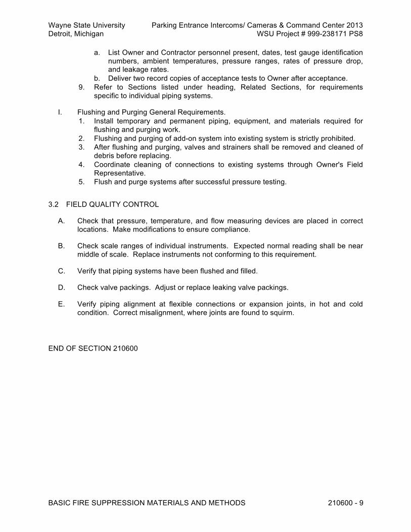
Wayne State University Parking Entrance Intercoms/ Cameras & Command Center 2013 Detroit, Michigan WSU Project # 999-238171 PS8
BASIC FIRE SUPPRESSION MATERIALS AND METHODS 210600 - 9
a. List Owner and Contractor personnel present, dates, test gauge identification numbers, ambient temperatures, pressure ranges, rates of pressure drop, and leakage rates.
b. Deliver two record copies of acceptance tests to Owner after acceptance. 9. Refer to Sections listed under heading, Related Sections, for requirements
specific to individual piping systems.
I. Flushing and Purging General Requirements. 1. Install temporary and permanent piping, equipment, and materials required for
flushing and purging work. 2. Flushing and purging of add-on system into existing system is strictly prohibited. 3. After flushing and purging, valves and strainers shall be removed and cleaned of
debris before replacing. 4. Coordinate cleaning of connections to existing systems through Owner's Field
Representative. 5. Flush and purge systems after successful pressure testing.
3.2 FIELD QUALITY CONTROL
A. Check that pressure, temperature, and flow measuring devices are placed in correct locations. Make modifications to ensure compliance.
B. Check scale ranges of individual instruments. Expected normal reading shall be near middle of scale. Replace instruments not conforming to this requirement.
C. Verify that piping systems have been flushed and filled.
D. Check valve packings. Adjust or replace leaking valve packings.
E. Verify piping alignment at flexible connections or expansion joints, in hot and cold condition. Correct misalignment, where joints are found to squirm.
END OF SECTION 210600

Wayne State University Parking Entrance Intercoms/ Cameras & Command Center 2013 Detroit, Michigan WSU Project # 999-238171 PS8
WATER-BASED FIRE-SUPPRESSION SYSTEMS 211000 - 1
SECTION 211000 - WATER-BASED FIRE-SUPPRESSION SYSTEMS
PART 1 GENERAL
1.1 RELATED REQUIREMENTS
A. Section 21 0500 - Common Work Results for Fire Suppression.
B. Section 21 0600 - Basic Fire Protection Materials and Methods.
C. Section 21 1008 - Hangers and Supports for Fire Protection.
D. Division 26 - Electrical. 1.2 REFERENCE STANDARDS
A. ASME B31.1 - Power Piping ; 2007 (ANSI/ASME B31.1).
B. ASTM A47/A47M - Standard Specification for Ferritic Malleable Iron Castings ; 1999 (Reapproved 2004).
C. ASTM A536 - Standard Specification for Ductile Iron Castings ; 1984 (Reapproved 2004).
D. ASTM D2000 - Standard Classification System for Rubber Products in Automotive Applications ; 2008.
E. FM P7825 - Approval Guide ; current edition.
F. NFPA 13 - Standard for the Installation of Sprinkler Systems ; 2007.
G. UL (FPED) - Fire Protection Equipment Directory ; current edition. 1.3 SUBMITTALS
A. Refer to Section 01 3000 – Administrative Requirements, for submittal procedures. 1. For Review.
a. Shop Drawings. 1) Location and elevation of.
(a) Water supply piping. (b) Automatic sprinkler riser location.
2) Fabrication of overhead system network. 2. For Information.
a. Product data. 1) Alarm check valve. 2) Dry pipe valve. 3) Alarm and supervisory devices.

Wayne State University Parking Entrance Intercoms/ Cameras & Command Center 2013 Detroit, Michigan WSU Project # 999-238171 PS8
WATER-BASED FIRE-SUPPRESSION SYSTEMS 211000 - 2
4) System identification nameplates. 5) Sprinkler heads. 6) Pipe hangers and supports.
b. Design data. 1) Hydraulic calculations and associated drawings for fire protection
system. c. Test reports.
1) Test certificates for hydrostatic testing of system in accordance with NFPA 13.
d. Certificates. 1) Test of sprinkler network. 2) Underwriters Laboratories listed equipment.
3. For Closeout. a. Operation and Maintenance Data.
1) Spare parts lists.
1.4 QUALITY ASSURANCE
A. Hydraulically design systems according to criteria indicated on drawings.
B. Minimum sprinkler operating pressure: 7 psi.
C. Maximum water velocity in pipe: 32 feet per second.
D. Prepare hydraulic calculations on form sheets in accordance with NFPA 13.
E. Restate and include basic design data and criteria, work sheets, summary sheets, and supply and demand curves.
F. Clearly indicate hydraulic areas and reference points.
G. Submit calculations, for each area, to prove design area chosen is most hydraulically remote or most hydraulically demanding area.
H. Work shown on drawings is schematic or diagrammatic only. Scales and figure dimensions are approximate and are given for estimating purposes.
I. Drawings indicate general scheme for sprinkler system design. Call exceptions to scheme to Owner's Field Representative's attention, before proceeding with work.
J. Work shall be supervised and performed by personnel regularly engaged in installation of fire protection systems conforming to UL or NFPA Standards. Submit supervisor or installer evidence of qualification, upon request.
K. Furnish FM approved or UL listed devices and materials where FM approved or UL listed devices and materials are available.

Wayne State University Parking Entrance Intercoms/ Cameras & Command Center 2013 Detroit, Michigan WSU Project # 999-238171 PS8
WATER-BASED FIRE-SUPPRESSION SYSTEMS 211000 - 3
1.5 DELIVERY, STORAGE, AND HANDLING
A. Refer to Section 01 6000 - Product Requirements, for transportation, storage, and handling requirements.
1.6 WARRANTY
A. Refer to Section 01 7800 - Closeout Submittals, for additional warranty requirements. PART 2 PRODUCTS 2.1 SYSTEMS
A. Automatic Sprinkler System (Wet). 1. Pipe and fittings.
a. Galvanized or black steel pipe and fittings in accordance with NFPA 13. 2. Valves.
a. General service fire protection valves.
B. Automatic Sprinkler System (Dry). 1. Pipe and fittings.
a. Galvanized steel pipe and fittings in accordance with NFPA 13. 2. Valves.
a. General service fire protection valves. 2.2 MANUFACTURED UNITS
A. General Service Fire Protection Valves. 1. Valves listed are standard Specifications for fire protection service. 2. Where revisions or clarifications are required to establish specific requirements for
systems on this project, these are specified under respective service listed.
Type Rating Size Material Remarks OS and Y
gate valve 175 psi Through 2
inch Bronze threaded
Wedge disc Kennedy Fig. 66
OS and Y gate valve
175 psi 2-1/2 through 14 inch
Iron flanged Double disc Kennedy Fig. 68
NRS gate valve
175 psi 4 through 14 inch
Iron mechanical joint
Double disc Kennedy Fig. 71X
Globe valve 200 pound WOG
Through 2 inch
Bronze threaded
Renewable disc Kennedy Fig. 97-SD
Angle valve 200 pound WOG
Through 2 inch
Bronze threaded
Renewable disc Kennedy Fig. 98-SD

Wayne State University Parking Entrance Intercoms/ Cameras & Command Center 2013 Detroit, Michigan WSU Project # 999-238171 PS8
WATER-BASED FIRE-SUPPRESSION SYSTEMS 211000 - 4
Check valve 200 pound WOG
Through 2 inch
Bronze threaded
Regrindable seat Kennedy Fig. 440-SD
Check valve 175 psi 2-1/2 through 12 inch
Iron body flanged
Bronze disc Kennedy Fig. 126A
Check valve 175 psi 4 through 8 inch
Cast iron body
Wafer type Mueller Model A-2102
Butterfly valve
175 psi 4 through 12 inch
Ductile iron EDPM seat
Gear operated Kennedy No. 911
3. Kennedy valve or Mueller valve figure numbers are used to establish style,
quality, and weight. 4. Acceptable manufacturers.
a. Crane. b. Jenkins. c. Kennedy. d. Mueller. e. Nibco. f. Substitutions: See Section 01 6000 - Product Requirements.
B. Fire Protection Specialty Valves. 1. Alarm check valves.
a. Variable pressure, spring loaded, clapper type. b. Rubber faced clapper, hand hole covers, required trim, and main drain
system. c. Moving parts constructed of brass, bronze, stainless steel, or EPDM. d. Design clapper to prevent accumulation of dirt. e. Acceptable manufacturers.
1) GEM 2) Reliable. 3) Victaulic. 4) Viking. 5) Substitutions: See Section 01 6000 - Product Requirements.
2. Dry pipe valves. a. Low differential type with accelerator, automatic air control, including
trimmings, filters, air relief valves, regulators, pressure gauges, and drains. b. Acceptable manufacturers.
1) GEM 2) Reliable. 3) Victaulic. 4) Viking. 5) Substitutions: See Section 01 6000 - Product Requirements.
C. Fire Protection Hose Valves and Stations. 1. Class I fire hose valves.
a. 2-1/2 inch, heavy-duty angle valve with replaceable stem and valve seat, male outlet threads conforming to local standards, full flow override, designed for 300 psi working pressure.
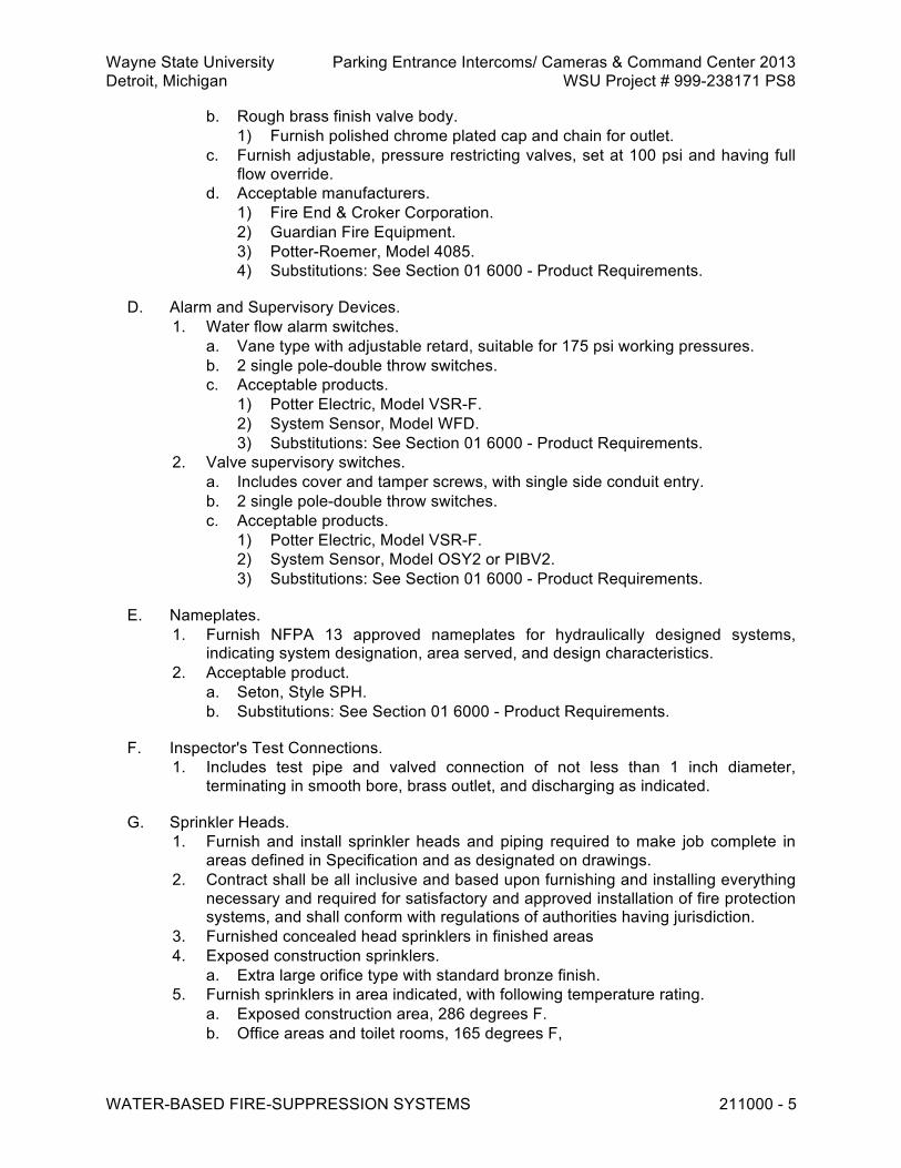
Wayne State University Parking Entrance Intercoms/ Cameras & Command Center 2013 Detroit, Michigan WSU Project # 999-238171 PS8
WATER-BASED FIRE-SUPPRESSION SYSTEMS 211000 - 5
b. Rough brass finish valve body. 1) Furnish polished chrome plated cap and chain for outlet.
c. Furnish adjustable, pressure restricting valves, set at 100 psi and having full flow override.
d. Acceptable manufacturers. 1) Fire End & Croker Corporation. 2) Guardian Fire Equipment. 3) Potter-Roemer, Model 4085. 4) Substitutions: See Section 01 6000 - Product Requirements.
D. Alarm and Supervisory Devices. 1. Water flow alarm switches.
a. Vane type with adjustable retard, suitable for 175 psi working pressures. b. 2 single pole-double throw switches. c. Acceptable products.
1) Potter Electric, Model VSR-F. 2) System Sensor, Model WFD. 3) Substitutions: See Section 01 6000 - Product Requirements.
2. Valve supervisory switches. a. Includes cover and tamper screws, with single side conduit entry. b. 2 single pole-double throw switches. c. Acceptable products.
1) Potter Electric, Model VSR-F. 2) System Sensor, Model OSY2 or PIBV2. 3) Substitutions: See Section 01 6000 - Product Requirements.
E. Nameplates. 1. Furnish NFPA 13 approved nameplates for hydraulically designed systems,
indicating system designation, area served, and design characteristics. 2. Acceptable product.
a. Seton, Style SPH. b. Substitutions: See Section 01 6000 - Product Requirements.
F. Inspector's Test Connections. 1. Includes test pipe and valved connection of not less than 1 inch diameter,
terminating in smooth bore, brass outlet, and discharging as indicated.
G. Sprinkler Heads. 1. Furnish and install sprinkler heads and piping required to make job complete in
areas defined in Specification and as designated on drawings. 2. Contract shall be all inclusive and based upon furnishing and installing everything
necessary and required for satisfactory and approved installation of fire protection systems, and shall conform with regulations of authorities having jurisdiction.
3. Furnished concealed head sprinklers in finished areas 4. Exposed construction sprinklers.
a. Extra large orifice type with standard bronze finish. 5. Furnish sprinklers in area indicated, with following temperature rating.
a. Exposed construction area, 286 degrees F. b. Office areas and toilet rooms, 165 degrees F,

Wayne State University Parking Entrance Intercoms/ Cameras & Command Center 2013 Detroit, Michigan WSU Project # 999-238171 PS8
WATER-BASED FIRE-SUPPRESSION SYSTEMS 211000 - 6
6. Furnish and install as directed by Owner's representative, steel sprinkler emergency cabinets, each containing 12 automatic sprinklers and appropriate wrenches.
7. Stock of extra sprinklers shall include proportionate quantities of types and temperature ratings installed.
8. Total number of spare sprinklers shall not be less than 3 percent of total number installed.
9. Acceptable manufacturers. a. ASCOA Fire Systems. b. Gem. c. Reliable. d. Victaulic. e. Viking. f. Substitutions: See Section 01 6000 - Product Requirements.
H. Pipe Hangers and Supports. 1. Furnish pipe supports and hangers in accordance with requirements specified in
Section 22 0529 and as detailed on drawings. 2.3 MATERIALS
A. Piping and Fittings. 1. Except as otherwise specified, furnish pipe and fittings for fire protection systems
in accordance with NFPA 13. 2. Grooved fittings: ASTM A47 malleable iron, pressure rated to match coupling. 3. Grooved flanges: ASTM A536 ductile iron, rated at 175 pounds. 4. Grooved couplings: ASTM A47 malleable iron or ASTM A536 ductile iron with
ASTM D2000 EPDM slip-on rubber gaskets, coupling bolts and nuts, and rated for not less than 300 pounds.
5. Snap lock or plain end type couplings are prohibited. 6. Install rigid couplings for vertical pipe risers. 7. Acceptable products.
a. Anvil, Gruvlok Figs. 7000 or 7001. b. Victaulic, Styles 75 or 77. c. Substitutions: See Section 01 6000 - Product Requirements.
PART 3 EXECUTION 3.1 INSTALLATION
A. Water Pressure During Construction. 1. To maintain pressure, temporarily blank off open ends of sprinkler lines or mains
from fire protection risers, as installation progresses. 2. Keep systems not subject to freezing in service during installation shutdown
periods.

Wayne State University Parking Entrance Intercoms/ Cameras & Command Center 2013 Detroit, Michigan WSU Project # 999-238171 PS8
WATER-BASED FIRE-SUPPRESSION SYSTEMS 211000 - 7
B. Pipe Systems. 1. Install piping and appurtenances in accordance with applicable provisions of
NFPA 13, ASME B31.1, and requirements of authorities having jurisdiction. 2. Pitch pipe to drain at riser. 3. Avoid low or trapped points. 4. Install discharge drains at each sprinkler riser and where sprinklers are trapped. 5. Install flanged connections at base of risers, at alarm check valves or dry pipe
valves, at fittings where feed mains or cross mains to each floor leave riser or supply main, at feed end of long runs of pipe, and at control valves.
6. Segmentally welded steel fittings or welded mitered joints will not be accepted. 7. Where branch is one or more sizes smaller than run, make welded branch
connections with standard weight connectors. a. Acceptable products.
1) Weld-o-lets by Bonney Forge and Tool Works. 2) Thread-o-lets by Wheeling Machine Products. 3) Branchlets by Allied Piping Products. 4) Substitutions: See Section 01 6000 - Product Requirements.
8. Where grooved joints are acceptable, install only those grooved couplings and fittings specified.
9. Substitution of other model, style, size, or rating of couplings, flanges, or fittings is prohibited.
C. Alarm and Supervisory Devices. 1. Install and adjust electric water flow alarms to prevent false alarm due to pressure
surges within closed sprinkler pipes. 2. Install alarm bells where indicated. 3. Install alarm and supervisory devices ready for wiring. 4. Wiring not included. 5. Locate inspector's test connections at accessible point not over 7 feet above floor. 6. In areas of exposed construction, install automatic sprinklers below ductwork and
other obstructions, sized over 48 inches in width, in accordance with NFPA 13. 7. After finish painting, install reflective paint numerals or letters, identifying each
automatic sprinkler riser, as directed by Owner. 8. Install nameplates on hydraulically designed systems. 9. Install nameplates on automatic sprinkler risers for hydraulically designed
systems.
D. Pipe Hanger and Support. 1. Install hangers and supports as specified in Section 21 1008 and as detailed on
drawings. 2. Space hangers in accordance with NFPA 13. 3. Secure supports, for piping under exposed concrete construction, to concrete
work with concrete inserts. 4. Locate inserts on the forms before concrete is poured or use hard cased
expansion shields. 5. Wooden, lead, or plastic plugs used for fastening, are prohibited.

Wayne State University Parking Entrance Intercoms/ Cameras & Command Center 2013 Detroit, Michigan WSU Project # 999-238171 PS8
WATER-BASED FIRE-SUPPRESSION SYSTEMS 211000 - 8
3.2 FIELD QUALITY CONTROL
A. Test and Acceptance. 1. Test fire protection system in accordance with applicable requirements specified
in Section 21 0600 and as specified in this Section. 2. Upon completion of work, notify proper insurance authorities and Owner's
representative. 3. Arrange to have authorized inspector in attendance when final job inspections and
tests are conducted. 4. All parts of completed sprinkler networks shall be hydrostatically pressure tested
at 200 pounds per square inch for minimum 2 hour period. 5. Furnish certificate giving results of each test. 6. Test, flush, and repair aboveground piping in walls, slabs, or sleeves, in presence
of insurance authority specified, before concealing. 7. Purge automatic sprinkler systems of trapped air by operating inspector's test
connection. 8. Test and actuate electric water flow alarm devices for alarm sensitivity and
performance.
END OF SECTION 211000

Wayne State University Parking Entrance Intercoms/ Cameras & Command Center 2013 Detroit, Michigan WSU Project # 999-238171 PS8
HANGERS AND SUPPORTS FOR FIRE PROTECTION 211008 - 1
SECTION 211008 - HANGERS AND SUPPORTS FOR FIRE PROTECTION PART 1 GENERAL
1.1 REFERENCE STANDARDS
A. AISC (COMM) - Commentary on the Specification for Structural Steel Buildings--Allowable Stress Design and Plastic Design ; 1989.
B. ASTM A36/A36M - Standard Specification for Carbon Steel ; 2008.
C. ASTM A575 - Standard Specification for Steel Bars, Carbon, Merchant Quality, M-Grades ; 1996 (Reapproved 2007).
D. AWS D1.1/D1.1 M - Structural Welding Code - Steel ; 2008. 1.2 SUBMITTALS
A. For Review. 1. Shop drawings.
a. Pipe hanger and support installation details, including details and locations of seismic or sway bracing, pipe anchors, and anchor bracing.
b. Include dimensioned location and method of attachment to building structure. c. Where pipe hangers cannot be hung from building structure, submit proposed
method of installing additional structural steel that connects to building structure.
1.3 QUALITY ASSURANCE
A. Qualifications. 1. Supplemental steel welding procedures, in accordance with section, Qualification,
of AWS D1.1. 2. Only welders who have successfully passed examination for this class of work
shall be employed to execute structural strength welds. 3. Examination shall have been within past six months, unless welder has been
making this type of weld after passing test within two years, as specified under qualification procedures of AWS D1.1.
PART 2 PRODUCTS 2.1 MANUFACTURED UNITS
A. Adjustable Swivel Ring Hangers. 1. Heavy steel construction with swivel nut and locknut. 2. Acceptable products.
a. B-Line, Fig. B3170.

Wayne State University Parking Entrance Intercoms/ Cameras & Command Center 2013 Detroit, Michigan WSU Project # 999-238171 PS8
HANGERS AND SUPPORTS FOR FIRE PROTECTION 211008 - 2
b. Carpenter and Paterson, Fig. 800. c. Anvil International Inc., Fig. 69. d. Substitutions: See Section 01 6000 - Product Requirements.
B. Clevis Hangers. 1. Heavy steel with adjustable nut and locknut. 2. Include spreaders on cross bolts of hangers for pipe sized 10 inches and larger. 3. Acceptable products.
a. B-Line, Fig. B3100. b. Carpenter and Paterson, Fig. 100. c. Anvil International Inc., Fig. 260. d. Substitutions: See Section 01 6000 - Product Requirements.
C. V-Clevis Hangers. 1. Heavy steel with adjustable nut and locknut. 2. Acceptable products.
a. B-Line, Fig. B3106. b. Carpenter and Paterson, Fig. 200VT. c. Substitutions: See Section 01 6000 - Product Requirements.
D. Trapeze Hangers. 1. Two-structural channels, back to back, with spacers welded at least on each end,
at top and bottom of channels. 2. Size channels with consideration to total weight to be supported, overall span
between hanger rods, and so as not to deflect more than 1/240 of span (5/16 inch in 6 feet 3 inches).
3. Assume piping to be supported is full of water. 4. Submit detailed drawings for Owner's Field Representative review.
E. Beam Clamps for Pipe 2 Inches and Smaller. 1. Side type.
a. Acceptable products. 1) B-Line: Fig. B3045. 2) Carpenter and Paterson: Fig. 18. 3) Anvil International Inc.: Fig. 217. 4) Substitutions: See Section 01 6000 - Product Requirements.
2. Side I type. a. Acceptable products.
1) Carpenter and Paterson: Fig. 45. 2) Anvil International Inc.: Fig. 225. 3) Substitutions: See Section 01 6000 - Product Requirements.
3. Adjustable type. a. Acceptable products.
1) B-Line: Fig. B3040. 2) Carpenter and Paterson: Fig. 14. 3) Anvil International Inc.: Fig. 14. 4) Substitutions: See Section 01 6000 - Product Requirements.
F. I-Beam Clamps. 1. For pipe sized 2-1/2 through 12 inches, with swing nuts.

Wayne State University Parking Entrance Intercoms/ Cameras & Command Center 2013 Detroit, Michigan WSU Project # 999-238171 PS8
HANGERS AND SUPPORTS FOR FIRE PROTECTION 211008 - 3
a. Acceptable products. 1) B-Line: Fig. B3050. 2) Carpenter and Paterson: Fig. 15. 3) Anvil International Inc.: Fig. 133 and 134. 4) Substitutions: See Section 01 6000 - Product Requirements.
G. Hanger Rods. 1. Threaded, hot rolled, steel rod conforming to ASTM A36 or A575. 2. Hanger rod may be continuously threaded. 3. Use of rod couplings is prohibited.
H. Hanger Rod Anchors. 1. Secure supports for piping under exposed concrete construction, to concrete work
with concrete inserts. 2. Acceptable products.
a. Hilti: Kwik Bolt TZ. b. Powers Fasteners: Power-Stud and SD2. c. Simpson Strong Tie-Strong Bolts. d. Substitutions: See Section 01 2500 - Substitutions.
3. Wooden, lead, or plastic plugs used for fastening are prohibited. 2.2 MATERIALS
A. Pipe Hanger and Supporting Materials. 1. Represent minimum requirements for mechanical work in general. 2. Furnish hanger and supporting materials meeting seismic requirements of local
codes and governing authorities. See Section 01 4100 - Regulatory Requirements - Seismic Control.
3. Furnish Factory Mutual approved or Underwriters Laboratories listed Hanger and supporting materials for Fire Protection work.
PART 3 EXECUTION 3.1 INSTALLATION
A. Install hanger and supporting materials in accordance with specified requirements, and in accordance with seismic requirements dictated by local codes and governing authorities. 1. Submit typical details and locations for review.
B. C-clamps without retainer clips and heat-treated spring steel clips that bite into building steel are prohibited as means of fastening pipe hangers to building structure.
C. Clamps that result in eccentric loads (twisting moments) on structural members of building, except for piping sized 2 inches and smaller, are also prohibited.

Wayne State University Parking Entrance Intercoms/ Cameras & Command Center 2013 Detroit, Michigan WSU Project # 999-238171 PS8
HANGERS AND SUPPORTS FOR FIRE PROTECTION 211008 - 4
D. Support piping from building structural frame, not from roof deck, permanent metal forms for concrete floors, concrete slabs (unless indicated otherwise), or from other pipe, duct, or equipment.
E. Contractor's attention is directed to drawing details and building structural framing layout that may require hanger spacing more frequently than spacings shown in table below. 1. Loading at any support point shall not exceed 1000 pounds, unless specifically
indicated otherwise. Screwed or welded steel pipe (liquid or vapor)
Pipe Size Maximum Hanger Spacing Minimum Rod Size 1/2 to 1 inch 8 feet 3/8 inch 1-1/4 through 2 inches 10 feet 3/8 inch 2-1/2 to 3-1/2 inches 12 feet 1/2 inch 4 and 5 inches 12 feet 5/8 inch 6 inches 12 feet 3/4 inch 8 and 10 inches 12 feet 7/8 inch
Grooved end steel pipe (liquid or vapor)
Pipe Size Maximum Hanger Spacing Minimum Rod Size 1/2 to 1 inch 8 feet 3/8 inch 1-1/4 through 2 inches 10 feet 3/8 inch 2-1/2 to 3 inches 12 feet 1/2 inch 4 inches 12 feet 5/8 inch 6 inches 12 feet 3/4 inch 8 and 10 inches 12 feet 7/8 inch
F. Fire Protection Piping. 1. Smaller than 4 inches: Install adjustable swivel ring type or clevis type hangers. 2. 4 inches and larger: Clevis type hangers.
G. Pipes Supported Individually From Structural Steel. 1. Support horizontal pipes running perpendicular to steel joists or trusses, building
roof purlins or floor beams (not T's) by means of beam clamps. 2. Beam clamps for supporting pipe sized 2 inches and smaller, hung from steel
joists or trusses, purlins or floor beams, (not T's) may be one of following. a. Side beam clamp. b. Side I-beam clamp. c. Adjustable beam clamp.
3. Support horizontal pipes running parallel to steel joists or trusses, purlins or floor beams (not T's) as specified above for piping running perpendicular, except where vertical truss member precludes hanging from purlin in concentric manner. Under these circumstances, piping shall be supported as specified for trapeze supports.

Wayne State University Parking Entrance Intercoms/ Cameras & Command Center 2013 Detroit, Michigan WSU Project # 999-238171 PS8
HANGERS AND SUPPORTS FOR FIRE PROTECTION 211008 - 5
H. Trapeze Supports. 1. Trapeze supports may be used to support one or more pipes grouped together
and hung from building steel as detailed on drawings. 2. Select beam clamp size and corresponding rod size for given trapeze support so
as not to exceed loads scheduled on drawings. 3. As option to hanging piping from trapeze support using hanger devices specified,
trapeze support below piping may be used as means of support. 4. When this option is used, pipe shall be secured to trapeze support with standard
U-bolts and locknuts.
I. Vertical Pipe Supports. 1. Support vertical runs of pipe not subject to appreciable expansion with wrought
steel clamps securely clamped to risers. 2. Support and laterally brace at each floor level, but at intervals not to exceed 16
feet.
J. Where necessary for proper system functioning, brace piping and supports against reaction sway and vibration.
K. For concentrated loads, such as valves, reduce allowable span proportionately.
L. Vertical risers shall be supported independently of connected horizontal piping whenever practical, with fixed supports at base and at intervals to accommodate system range of load and thermal conditions, and shall be guided for lateral stability. 1. Only one rigid support shall be installed for risers subjected to expansion at
approximately 1/3 point from top, unless otherwise indicated.
M. After piping systems have been installed, tested, and placed in satisfactory operation, firmly tighten hanger rod nut and jam nut and upset threads to prevent movement of fasteners.
N. Welding to Building Structure. 1. Welding to building structure is not allowed, unless otherwise specified or
specifically accepted by Owner's Field Representative 2. If so specified or accepted, comply with following requirements.
a. Unless otherwise noted, welding and workmanship shall be governed by AISC Specifications for the Design, Fabrication and Erection of Structural Steel for Buildings in conjunction with AWS D1.1.
b. Allowable stresses in field applied welds using E70 Series and A36 steel. 1) Tension or compression: Same as base metal. 2) Shear: 15,800 pounds per square inch.
O. Surfaces to be welded shall be free from loose slag, scale, rust, grease, paint, or other foreign material.
P. Before welding, painted surfaces shall have paint removed to expose clean steel surface. 1. Special attention is called to requirement that maximum size of fillet weld that may
be assumed in design of connection shall ensure that stresses in adjacent base material do not exceed allowable value for this material.

Wayne State University Parking Entrance Intercoms/ Cameras & Command Center 2013 Detroit, Michigan WSU Project # 999-238171 PS8
HANGERS AND SUPPORTS FOR FIRE PROTECTION 211008 - 6
Q. No welds transmitting calculated stress shall be less than 3 inches in length, and no intermittent welds shall be less than 2 inches in length.
R. No welds shall be applied to flanges of tension members perpendicular to direction of stress.
S. Turn side and end fillet welds around corners for minimum length of twice nominal size of weld.
T. Length of end returns is not to be included in calculated weld length.
U. No welding or other operation involving use of flame, arcs, or sparking devices will be allowed without written permission of Owner's Field Representative.
V. Welds found to be in nonconformance to requirements of AWS D1.1 shall be repaired or replaced according to workmanship section of AWS D1.1 at no cost to Owner.
END OF SECTION 211008

Wayne State University Parking Entrance Intercoms/ Cameras & Command Center 2013 Detroit, Michigan WSU Project # 999-238171 PS8
COMMON WORK RESULTS FOR PLUMBING 220513 - 1
SECTION 220513 - COMMON WORK RESULTS FOR PLUMBING
PART 1 GENERAL 1.1 REFERENCE STANDARDS
A. ASTM C109 - Standard Test Method for Compressive Strength of Hydraulic Cement Mortars; 2005.
B. ASTM C531 - Standard Test Method for Linear Shrinkage and Coefficient of Thermal Expansion of Chemical Resistant Mortars, Grouts, Monolithic Surfacings, and Polymer Concretes; 2005.
C. ASTM C579 - Standard Test Methods for Compressive Strength of Chemical-Resistant Mortars, Grouts, Monolithic Surfacings, and Polymer Concretes ; 2001.
D. ASTM C827 - Change in Height at Early Ages of Cylindrical Specimens from Cementitious Mixtures; 2001a (Reapproved 2005).
E. Institute of Electrical and Electronics Engineers (IEEE).
F. National Electrical Manufacturers Association (NEMA) MG 1 - Motors and Generators ; 2003.
G. NFPA 70 - National Electrical Code (NEC) ; 2008.
H. OSHA - Occupational Safety and Health Act, latest edition. 1.2 ADMINISTRATIVE REQUIREMENTS
A. Coordinate installation of plumbing, piping, fire protection and ductwork including associated support systems with existing systems and supports and other building trades, equipment, and systems, so as to avoid interferences between individual trades and between trades and building construction.
B. Design of fire protection, plumbing, mechanical and electrical systems in ceiling space and truss space has been coordinated to avoid interferences between major components of each system. 1. Final coordination of components shall be performed by installation contractors. 2. Contract documents include suggested ceiling space and truss space zoning
concepts to assist contractors in final coordination.
C. Prepare plumbing installation drawings for purpose of coordination with other trades. Sheet metal contractor shall be responsible for collecting installation documentation from mechanical, electrical, and information technology (IT) trades and create coordination drawings.
D. General Contractor shall distribute final coordination drawings to all contractors.
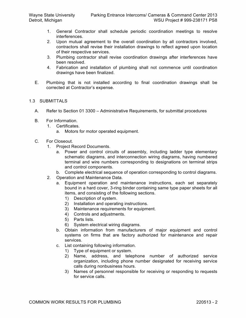
Wayne State University Parking Entrance Intercoms/ Cameras & Command Center 2013 Detroit, Michigan WSU Project # 999-238171 PS8
COMMON WORK RESULTS FOR PLUMBING 220513 - 2
1. General Contractor shall schedule periodic coordination meetings to resolve interferences.
2. Upon mutual agreement to the overall coordination by all contractors involved, contractors shall revise their installation drawings to reflect agreed upon location of their respective services.
3. Plumbing contractor shall revise coordination drawings after interferences have been resolved.
4. Fabrication and installation of plumbing shall not commence until coordination drawings have been finalized.
E. Plumbing that is not installed according to final coordination drawings shall be corrected at Contractor’s expense.
1.3 SUBMITTALS
A. Refer to Section 01 3300 – Administrative Requirements, for submittal procedures
B. For Information. 1. Certificates.
a. Motors for motor operated equipment.
C. For Closeout. 1. Project Record Documents.
a. Power and control circuits of assembly, including ladder type elementary schematic diagrams, and interconnection wiring diagrams, having numbered terminal and wire numbers corresponding to designations on terminal strips and control components.
b. Complete electrical sequence of operation corresponding to control diagrams. 2. Operation and Maintenance Data.
a. Equipment operation and maintenance instructions, each set separately bound in a hard cover, 3-ring binder containing same type paper sheets for all items, and consisting of the following sections. 1) Description of system. 2) Installation and operating instructions. 3) Maintenance requirements for equipment. 4) Controls and adjustments. 5) Parts lists. 6) System electrical wiring diagrams.
b. Obtain information from manufacturers of major equipment and control systems on firms that are factory authorized for maintenance and repair services.
c. List containing following information. 1) Type of equipment or system. 2) Name, address, and telephone number of authorized service
organization, including phone number designated for receiving service calls during nonbusiness hours.
3) Names of personnel responsible for receiving or responding to requests for service calls.

Wayne State University Parking Entrance Intercoms/ Cameras & Command Center 2013 Detroit, Michigan WSU Project # 999-238171 PS8
COMMON WORK RESULTS FOR PLUMBING 220513 - 3
1.4 QUALITY ASSURANCE
A. Use vendors and equipment manufacturers capable of furnishing local support.
B. Materials and equipment shall be purchased for this project with manufacturer's full warranty, and certified as specified manufacturer's products. Unacceptable are surplus materials from other projects, obsolete or discontinued products, and products rebuilt, remanufactured, or altered in materials, markings, labels, or nameplates.
C. Furnish equipment that is listed and labeled. 1. Listed and Labeled as defined in NEC Article 100. 2. Listing and Labeling Agency Qualifications, a Nationally Recognized Testing
Laboratory (NRTL) as defined in OSHA Regulation 1910.7.
D. While Owner's Field Representative's drawings and Specifications propose to be complete in all respects as to layout, type of equipment, and materials, drawings and Specifications are not intended to serve as detailed system or equipment location drawings.
E. Prepare detailed piping, sleeve, or insert installation drawings, and equipment location drawings.
F. Submit detailed pipe and equipment supports indicating location of miscellaneous steel and building steel connections.
G. System drawings shall locate each system in relation to other systems, to electrical work, and to building structure.
H. Mark drawings to identify function of each item, location, and proposed system where item is to be installed.
I. Include Contract drawing on which item is shown and page in Specifications where item is described.
J. If code designation letters are used to identify the specific design of submitted equipment and components, and if code designations are not clearly defined in manufacturer's published literature, submit glossary identifying in complete detail the meaning of code designations used.
K. Factory furnished equipment and controllers shall be designed to prevent power line disturbances, such as spikes, harmonics, and other irregularities in sine wave configuration of fundamental.
L. Furnish filters or other devices that limit back feeding of disturbances into power supply system and limiting harmonics content to not more than 3 percent of fundamental.
M. Voltage spikes shall not exceed 150 percent of peak system voltage.

Wayne State University Parking Entrance Intercoms/ Cameras & Command Center 2013 Detroit, Michigan WSU Project # 999-238171 PS8
COMMON WORK RESULTS FOR PLUMBING 220513 - 4
N. If equipment is found to destabilize building power supply, furnish, install, and interwire, at no change in Contract price, manufacturer accepted devices and circuits to restore power system stability.
1.5 DELIVERY, STORAGE, AND HANDLING
A. Deliver. 1. To site in original unopened containers and pallets bearing manufacturer's name
and brand. 2. Affix labels to products, pallets, and containers. 3. Delivered products and containers without complete labels may be rejected.
B. Store. 1. On level, aboveground platforms. 2. Keep containers dry and free from dust and other airborne contaminants. 3. Protect stored absorptive material from moisture damage. 4. Promptly remove adhesives and adhesive tapes from material and equipment
surfaces, where prolonged contact could damage surfaces.
C. Piping Systems. 1. Cover threaded pipe, fitting, and valve ends with thread protectors. 2. Support stored pipe to prevent permanent deformation from ovalizing, crushing, or
sagging. 3. Protect machined surfaces from nicks, dents, scratches, and abrasions, and
protect valve yokes, stems, handwheels, operators, and linkage from undue stresses.
4. Protect piping from dust and moisture.
D. Equipment. 1. Deliver in cartons, crates, or on sleepers. 2. Hoist, transport, rig, and store equipment to prevent damage. 3. Seal openings to prevent entry of dust, dirt, water, and other contaminants. 4. Store boxed equipment on shelves. 5. Crated equipment and equipment mounted on sleepers may be stored on ground,
if no part of equipment comes in contact with ground or with water. 1.6 WARRANTY
A. Refer to Section 01 7700 – Closeout Procedures, for additional warranty requirements.
PART 2 PRODUCTS 2.1 SYSTEM DESCRIPTION
A. Electrical System Characteristics. 1. Electrical supply.
a. Power: 480 volts, 3 phase, 60 hertz, and 120 volts, single phase, 60 hertz.

Wayne State University Parking Entrance Intercoms/ Cameras & Command Center 2013 Detroit, Michigan WSU Project # 999-238171 PS8
COMMON WORK RESULTS FOR PLUMBING 220513 - 5
b. Control: 120 volts and lower, single phase, 60 hertz, and 24 volt direct current.
2. Furnish and install for package, self-contained equipment. a. Electrical components.
1) Factory mounted. 2) Factory piped. 3) Factory wired.
(a) Wiring mounted on external surfaces of equipment factory installed within conduit.
4) Totally interconnected. b. Load side power connections. c. Mechanical and electrical controls.
2.2 MANUFACTURED UNITS
A. Motors. 1. Motor characteristics.
a. Ball bearing type. b. Rating equal to or greater than brake horsepower of connected load. c. Service factor: 115 percent of nameplate rating when operated in 40 degrees
C ambient. d. Deliver rated load continuously from 10 percent below to 10 percent above
rated voltage without decrease in expected motor life. e. Supply standard fractional size, single phase motors with resilient base
mounting. f. Open, dripproof motors for.
1) General application within the building. 2) Enclosed applications within unit housing (not in airstream).
g. Totally enclosed fan-cooled motors. 1) For outdoor installation where exposed to weather. 2) Where located within the air stream of supply or exhaust fans.
h. Motors Used With Variable Speed Drives. 1) Coordinate with variable speed drive manufacturer. 2) Class F or Class H insulation and Class B minimum temperature rise. 3) Sized to reflect extra duty required by high harmonic content of variable
speed drive output waveform. 4) Shaft voltage.
(a) Verify compatibility with drive by measuring shaft voltage upon commissioning and start-up.
(b) Furnish shaft grounding system installed on each motor. 2. Motors rated.
a. 1/4 horsepower and larger: 460 volt, 3 phase, 60 hertz. b. Under 1/4 horsepower: 115 volt, single phase, 60 hertz.
3. T-frame, integral horsepower motors rated 200 hp and less. a. Severe-duty, high-efficiency design.
1) When tested in accordance with IEEE 112, Test Method B, rated in accordance with NEMA, MG1-12.53A.
2) Show nominal efficiency on motor nameplates. 3) Nominal efficiencies defined by NEMA, MG1-12.53B and following table.

Wayne State University Parking Entrance Intercoms/ Cameras & Command Center 2013 Detroit, Michigan WSU Project # 999-238171 PS8
COMMON WORK RESULTS FOR PLUMBING 220513 - 6
T-Frame Motors
Nameplate
Horsepower Nominal Efficiency
Nameplate Horsepower
Nominal Efficiency
1/8 - 15 92.4 1/6 - 20 93 1/4 - 25 93.6 1/3 - 30 93.6 1/2 - 40 94.1 3/4 - 50 94.5 1 85.5 60 95 1-1/2 86.5 75 95.4 2 86.5 100 95.4 3 89.5 125 95.4 5 89.5 150 95.8 7-1/2 91.7 200 96.2 10 91.7 300 96.2
4. Acceptable manufacturers.
a. A.O. Smith Century. b. Baldor. c. General Electric Co. d. Howell Electric Motors. e. Lincoln. f. Reliance Electric. g. Siemens. h. Toshiba. i. U.S. Electrical Motors. j. Substitutions: See Section 01 6000 - Product Requirements.
2.3 MATERIALS
A. Housekeeping Pads. 1. Furnish and install anchor plates, foundation bolts, nuts, and washers for setting
of equipment. 2. Construct of 2500 psi concrete mixture, shaped to accommodate equipment it
supports, with smooth top surface and 1 inch beveled edges, sized not less than 4 inches above floor level and 2 inches beyond perimeter of supported equipment or equipment bedplate.
3. Furnish anchor plates, bolts, nuts, washers, and bolt inserts required for secure mounting of equipment.
4. Locate anchor bolt inserts in pouring forms prior to pouring concrete foundations and concrete housekeeping pads.
5. Maintain inserts in position and in proper alignment during pouring and setting of concrete.
6. Anchor bolts shall be screwed into inserts prior to concrete pour in order to maintain insert bolt holes free of concrete.
7. Wood, fiber, or lead insert plugs are prohibited.

Wayne State University Parking Entrance Intercoms/ Cameras & Command Center 2013 Detroit, Michigan WSU Project # 999-238171 PS8
COMMON WORK RESULTS FOR PLUMBING 220513 - 7
B. Grouting. 1. Furnish and install grout for setting of equipment bases, rails and bedplates, and
pipe supports located on building floors, concrete slabs, foundations, inertia blocks, and housekeeping pads.
2. Cementitious grout. a. Consist of premixed, prepackaged materials supplied by manufacturer,
requiring only the addition of potable water. b. Performance criteria (high-flow epoxy grout).
1) Zero shrinkage when tested in accordance with ASTM C827. 2) Effective bearing area not less than 95 percent in hardened state, when
measured in accordance with ASTM C827. 3) Compressive strength of not less than 5000 psi at 28 days when tested
in accordance with ASTM C109. 4) Containing no metallic particles, aluminum powder, or expansive cement.
c. Acceptable products. 1) L and M Construction Chemicals, Crystex. 2) Master Builders, Masterflow 928 and 713. 3) U.S. Grout, Five Star Grout. 4) Dayton Superior, Sure-Grip High Performance Grout. 5) Substitutions: See Section 01 6000 - Product Requirements.
3. Epoxy-based grout. a. Pourable, 100 percent solids epoxy system consisting of 3 premeasured,
prepackaged components. b. Performance criteria (regular epoxy grout).
1) Suitable for installation in annular spaces of 2 inches and greater. 2) Zero shrinkage when tested in accordance with ASTM C827. 3) Effective bearing area not less than 95 percent in hardened state, when
measured in accordance with ASTM C827. 4) Compressive strength measured in accordance with ASTM C579,
Method B. (a) Not less than 5000 psi at 24 hours. (b) Not less than 10,000 psi at 7 days.
5) Maximum thermal coefficient of expansion, 0.00003 inch per inch per degree F, when tested in accordance with ASTM C 531.
c. Acceptable products (regular epoxy grout). 1) Dayton Superior, Sure-Grip Epoxy Grout. 2) L and M Construction Chemicals, Epo Grout. 3) Master Builders Technologies, Brutem 19 Grout. 4) Philadelphia Resins, Chockfast Orange Grout. 5) U.S. Grout, Five Star Epoxy Grout. 6) Substitutions: See Section 01 6000 - Product Requirements.
4. High-flow epoxy grout a. Performance criteria (high flow epoxy grout).
1) Suitable for installation in annular spaces of less than 2 inches. 2) Zero shrinkage when tested in accordance with ASTM C827. 3) Effective bearing area not less than 95 percent in hardened state, when
measured in accordance with ASTM C827. 4) Compressive strength measured in accordance with ASTM C579,
Method B.

Wayne State University Parking Entrance Intercoms/ Cameras & Command Center 2013 Detroit, Michigan WSU Project # 999-238171 PS8
COMMON WORK RESULTS FOR PLUMBING 220513 - 8
(a) Not less than 5000 psi at 24 hours. (b) Not less than 10,000 psi at 7 days.
5) Maximum thermal coefficient of expansion, 0.00003 inch per inch per degree F, when tested in accordance with ASTM C531.
b. Acceptable products (high flow epoxy grout). 1) Master Builders Technologies, 650 High Flow and Brutem 19-HF. 2) Philadelphia Resins, Chockfast Gray Grout. 3) U.S. Grout, Five Star Speed Epoxy Chock. 4) Substitutions: See Section 01 6000 - Product Requirements.
PART 3 EXECUTION 3.1 INSTALLATION
A. Disposal of Removed Materials and Equipment. 1. Take possession of and remove from Owner's premises, materials and equipment
indicated to be removed and not reinstalled. 2. Clean, protect from damage, and deliver to Owner, materials and equipment
indicated to be removed and not reinstalled.
B. Painting. 1. Include Section 09 9100 for painting plumbing work. 2. Equipment shall be either factory prime coated or factory finish painted. 3. Perform touch up where factory prime coat or factory finish have been scratched,
abraded, dulled, or otherwise damaged or rendered unsightly. 4. Touch up shall restore original finish as to color, texture, and gloss, and shall be
indistinguishable from original finish.
C. Openings in Building Structure. 1. For new piping, tubing, and conduit openings in existing concrete.
a. Locate reinforcing bars prior to coring hole by x-ray or other approved means. b. Do not cut reinforcing bars. c. Furnish and install pipe sleeves and caulk sleeves in position. d. Cut piping, tubing, and conduit openings in existing masonry by coring or with
drill points and chisels. 2. For piping, tubing, and conduit openings in new concrete.
a. Furnish and install sleeves in concrete formwork and maintain their position during pouring and setting of concrete.
b. Where concrete floors incorporate permanent metal forms, cut forms and install sleeves to penetrate metal forms.
3. For piping, tubing, and conduit openings in new masonry. a. Furnish sleeves to jobsite, for installation in other Sections. b. Coordinate location of sleeves with masonry work.
D. Cut Openings for Piping. 1. In smoke baffles, draft curtains, or vertical metal deck closures neat and straight,
without dents or jagged edges. 2. Opening sizes shall not be larger than piping passing through them.
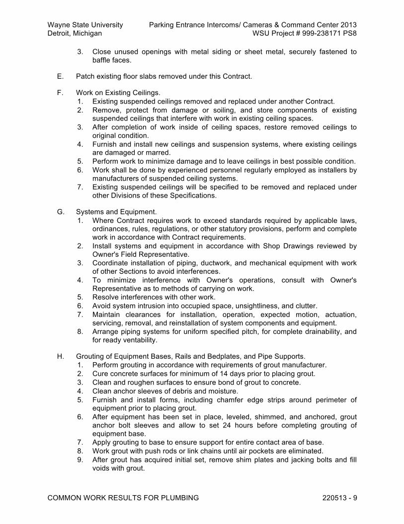
Wayne State University Parking Entrance Intercoms/ Cameras & Command Center 2013 Detroit, Michigan WSU Project # 999-238171 PS8
COMMON WORK RESULTS FOR PLUMBING 220513 - 9
3. Close unused openings with metal siding or sheet metal, securely fastened to baffle faces.
E. Patch existing floor slabs removed under this Contract.
F. Work on Existing Ceilings. 1. Existing suspended ceilings removed and replaced under another Contract. 2. Remove, protect from damage or soiling, and store components of existing
suspended ceilings that interfere with work in existing ceiling spaces. 3. After completion of work inside of ceiling spaces, restore removed ceilings to
original condition. 4. Furnish and install new ceilings and suspension systems, where existing ceilings
are damaged or marred. 5. Perform work to minimize damage and to leave ceilings in best possible condition. 6. Work shall be done by experienced personnel regularly employed as installers by
manufacturers of suspended ceiling systems. 7. Existing suspended ceilings will be specified to be removed and replaced under
other Divisions of these Specifications.
G. Systems and Equipment. 1. Where Contract requires work to exceed standards required by applicable laws,
ordinances, rules, regulations, or other statutory provisions, perform and complete work in accordance with Contract requirements.
2. Install systems and equipment in accordance with Shop Drawings reviewed by Owner's Field Representative.
3. Coordinate installation of piping, ductwork, and mechanical equipment with work of other Sections to avoid interferences.
4. To minimize interference with Owner's operations, consult with Owner's Representative as to methods of carrying on work.
5. Resolve interferences with other work. 6. Avoid system intrusion into occupied space, unsightliness, and clutter. 7. Maintain clearances for installation, operation, expected motion, actuation,
servicing, removal, and reinstallation of system components and equipment. 8. Arrange piping systems for uniform specified pitch, for complete drainability, and
for ready ventability.
H. Grouting of Equipment Bases, Rails and Bedplates, and Pipe Supports. 1. Perform grouting in accordance with requirements of grout manufacturer. 2. Cure concrete surfaces for minimum of 14 days prior to placing grout. 3. Clean and roughen surfaces to ensure bond of grout to concrete. 4. Clean anchor sleeves of debris and moisture. 5. Furnish and install forms, including chamfer edge strips around perimeter of
equipment prior to placing grout. 6. After equipment has been set in place, leveled, shimmed, and anchored, grout
anchor bolt sleeves and allow to set 24 hours before completing grouting of equipment base.
7. Apply grouting to base to ensure support for entire contact area of base. 8. Work grout with push rods or link chains until air pockets are eliminated. 9. After grout has acquired initial set, remove shim plates and jacking bolts and fill
voids with grout.

Wayne State University Parking Entrance Intercoms/ Cameras & Command Center 2013 Detroit, Michigan WSU Project # 999-238171 PS8
COMMON WORK RESULTS FOR PLUMBING 220513 - 10
10. After grout has cured, remove forms and trim grout to ensure smooth finish. 11. Tighten anchor bolts prior to start of equipment and retighten following initial
equipment operation. 3.2 FIELD QUALITY CONTROL
A. General. 1. Upon completion of work, prior to testing, conduct final inspection and ensure
fixtures, equipment, and piping have been cleaned and placed in complete and satisfactory working order.
B. Equipment. 1. Furnish manufacturer's factory authorized service for adjustments and start-up,
where required for preservation of guarantees. 2. Do not jog or start equipment until completion of factory authorized service. 3. Clean and degrease equipment. 4. Check nameplates for readability.
a. Remove paint smears. b. Where nameplates are illegible, arrange for replacement by equipment
manufacturer. 5. Motor driven equipment.
a. Start equipment and make sure thermal overload protection will not shut down motor during acceleration period.
b. Check motors for direction of rotation. c. Obtain assistance where required to reverse motor rotation. d. Check identification, instruction, and warning labels. e. Prepare lubrication schedule and deliver this schedule to Owner. f. Schedule for each piece of equipment to include.
1) Locations for lubricant application. 2) Type of lubricant. 3) Lubricating device. 4) Quantity of lubricant to be dispensed during each application. 5) Frequency of lubrication.
g. Check for factory applied lubrication and add lubricant where required. h. In particular, make sure extended lubricating lines are completely filled. i. Check bearing seals.
1) Replace blown seals with seals complying with Contract criteria. 2) Check associated bearings for foreign matter and damage. 3) Flush and relubricate, or furnish and install seals complying with Contract
criteria. j. Turn equipment shafts by hand to check for binding or rough bearing action.
1) Investigate causes of binding and rough bearing action. 2) Repair, adjust, or furnish and install components complying with Contract
criteria to achieve proper operation. 3) In particular, furnish and install roller and ball bearings complying with
Contract criteria if bearings exhibit evidence of race pitting, brinelling, rust, or discoloration.
k. Check rotating equipment for smooth operation. l. Rebalance or replace rough running equipment.

Wayne State University Parking Entrance Intercoms/ Cameras & Command Center 2013 Detroit, Michigan WSU Project # 999-238171 PS8
COMMON WORK RESULTS FOR PLUMBING 220513 - 11
m. Confirm shaft voltages are 3 volts or less to ground for motors used with variable speed drives.
6. Flush out corrosion inhibiting compounds, where applied by manufacturer to prevent deterioration in transit and storage.
7. Witness and certify Acceptance Document for each piece of equipment and each system.
END OF SECTION 220513

Wayne State University Parking Entrance Intercoms/ Cameras & Command Center 2013 Detroit, Michigan WSU Project # 999-238171 PS8
IDENTIFICATION FOR PLUMBING PIPING AND EQUIPMENT 220553 - 1
SECTION 220553 - IDENTIFICATION FOR PLUMBING PIPING AND EQUIPMENT PART 1 GENERAL 1.1 REFERENCE STANDARDS
A. ANSI A13.1 - Scheme for the Identification of Piping Systems. 1.2 SUBMITTALS
A. Refer to Section 01 3000 – Administrative Requirements, for submittal procedures.
B. For information. 1. Product data.
a. Pipe markers. b. Equipment identification labels.
1.3 DELIVERY, STORAGE, AND HANDLING
A. Refer to Section 01 6000 – Product Requirements, for transportation, storage, and handling requirements.
PART 2 PRODUCTS 2.1 SYSTEM DESCRIPTION
A. Pipe Markers. 1. Furnish and apply custom-made pipe markers to piping defined as follows.
a. Piping exposed to view. 1) Piping exposed to view includes piping located in equipment rooms or in
spaces that do not conceal the piping. 2) For piping exposed in the Ballroom, Atrium and Prefunction Ceiling refer
to architectural Room Finish Schedules for specific direction on painting and labeling
b. Piping located above suspended ceilings. c. Piping located in accessible shafts. d. Underground metallic piping. e. Underground nonmetallic piping.
2. Pipe markers shall identify fluid handled by each system. 3. Markers for insulated pipe and for bare pipe sized 3/4 inch and larger shall
indicate direction of fluid flow. 2.2 MANUFACTURED UNITS
A. Plumbing Identification (Piping).

Wayne State University Parking Entrance Intercoms/ Cameras & Command Center 2013 Detroit, Michigan WSU Project # 999-238171 PS8
IDENTIFICATION FOR PLUMBING PIPING AND EQUIPMENT 220553 - 2
1. Markers for pipe sized 3/4 inch and larger. a. Unless otherwise specified, comply with requirements of ANSI A13.1. b. Background of markers shall be color coded. c. Legends shall be in long form or they may be abbreviated only if they are in
common, everyday usage and not prone to misinterpretation. d. Directional arrows shall point away from legend. e. Pipe markers shall be plastic and coated to resist smudging and damage
from water and weather. f. Pipe markers shall be snap-on or strap-on type. g. Acceptable manufacturers.
1) W.H. Brady, Quick-Labels. 2) Craftmark Identification Systems, Specmark. 3) Marking Services, Inc. 4) Seton, Setmark. 5) Substitutions: See Section 01 6000 - Product Requirements
2. Markers for bare pipe smaller than 3/4 inch nominal size. a. Circular brass tags identifying service and suspended by means of brass jack
chains. 1) Legends shall be largest type which can be accommodated.
b. Snap-on labels specifically made for small diameter pipe and tubing. c. Acceptable manufacturers.
1) W.H. Brady, Style No. 28. 2) Craftmark Identification Systems. 3) Marking Services, Inc. 4) Seton, Valve Tags. 5) Substitutions: See Section 01 6000 - Product Requirements
B. Equipment Identification and Duplicate Motor Nameplate Data. 1. Laminated white plastic nameplates with black engraved letters. 2. Acceptable manufacturers.
a. W.H. Brady. b. Craftmark Identification Systems. c. Marking Services, Inc. d. Seton. e. Substitutions: See Section 01 6000 - Product Requirements
PART 3 EXECUTION 3.1 INSTALLATION
A. Plumbing Identification (Piping). 1. Apply pipe markers for piping specified to be painted, after painting has been
completed. 2. Prior to application of snap-on labels, or brass tags, remove debris and dust from
contact surfaces. 3. Unless otherwise specified, locate pipe markers in accordance with Article 3.1 of
ANSI A13.1, except with 50 foot maximum intervals. 4. Furnish and install markers on piping at connections to equipment.

Wayne State University Parking Entrance Intercoms/ Cameras & Command Center 2013 Detroit, Michigan WSU Project # 999-238171 PS8
IDENTIFICATION FOR PLUMBING PIPING AND EQUIPMENT 220553 - 3
5. Apply pipe markers for piping specified to be painted, after painting has been completed.
6. Prior to application of pipe markers, snap-on labels or brass tags, remove dust and debris from pipe surface.
7. Install pipe markers as follows. a. At access panels or doors. b. Adjacent to valves and branch connections. c. On both sides of floors, ceilings, and walkways. d. At major changes in direction. e. At maximum intervals of 25 feet on straight lengths of pipe . f. At termination points. g. At connections to equipment.
8. Arrow and marker placement shall furnish unobstructed visibility from floor level.
B. Mechanical Equipment. 1. Label in accordance with Owner's requirements. 2. When electric motor location renders nameplate data inaccessible, install
duplicate motor nameplate data in easily accessible location on equipment. 3.2 FIELD QUALITY CONTROL
A. Check factory installed nameplates for readability. 1. Remove paint smears. 2. Where nameplates are illegible, arrange for replacement by equipment
manufacturer.
B. Check directional arrows and apply corrected labels and arrows, where errors are found.
END OF SECTION 220553

Wayne State University Parking Entrance Intercoms/ Cameras & Command Center 2013 Detroit, Michigan WSU Project # 999-238171 PS8
BASIC PLUMBING MATERIALS AND METHODS 220600 - 1
SECTION 220600 - BASIC PLUMBING MATERIALS AND METHODS PART 1 GENERAL 1.1 RELATED REQUIREMENTS
A. Section 22 0513 - Common Work Results for Plumbing.
B. Section 22 0523 - Valves for Plumbing Systems.
C. Section 22 0553 - Identification for Plumbing Piping and Equipment
D. Section 22 0720 - Plumbing Piping Insulation.
E. Section 22 1008 - Hangers and Supports for Plumbing Piping and Equipment.
F. Section 22 3000 - Plumbing Equipment.
G. Section 22 4000 - Plumbing Fixtures
H. Division 26, Electrical.
I. Section 31 0000 - Earthwork for Buildings. 1.2 REFERENCE STANDARDS
A. ACI 301 - Specifications for Structural Concrete for Buildings ; 2005.
B. ASME B16.3 - Malleable Iron Threaded Fittings ; 1998 (R2006).
C. ASME B16.22 - Wrought Copper and Copper Alloy Solder Joint Pressure Fittings ; 2001 (R2005).
D. ASME B16.26 - Cast Copper Alloy Fittings for Flared Copper Tubes ; 2006.
E. ASTM A47/A47M - Standard Specification for Ferritic Malleable Iron Castings ; 1999 (Reapproved 2004).
F. ASTM A53/A53M - Standard Specification for Pipe, Steel, Black and Hot-Dipped, Zinc-Coated, Welded and Seamless ; 2007.
G. ASTM A105/A105M - Standard Specification for Carbon Steel Forgings for Piping Applications ; 2005.
H. ASTM A126 - Standard Specification for Gray Iron Castings for Valves, Flanges, and Pipe Fittings ; 2004.
I. ASTM A135/A135M - Standard Specification for Electric-Resistance-Welded Steel Pipe ; 2006.

Wayne State University Parking Entrance Intercoms/ Cameras & Command Center 2013 Detroit, Michigan WSU Project # 999-238171 PS8
BASIC PLUMBING MATERIALS AND METHODS 220600 - 2
J. ASTM A181/A181M - Standard Specification for Carbon Steel Forgings for General-Purpose Piping ; 2006.
K. ASTM A197/A197M - Standard Specification for Cupola Malleable Iron ; 2000 (Reapproved 2006).
L. ASTM A234/A234M - Standard Specification for Piping Fittings of Wrought Carbon Steel and Alloy Steel for Moderate and High Temperature Service ; 2007.
M. ASTM A536 - Standard Specification for Ductile Iron Castings ; 1984 (Reapproved 2004).
N. ASTM B32 - Standard Specification for Solder Metal ; 2004.
O. ASTM B306 - Standard Specification for Copper Drainage Tube (DWV) ; 2002.
P. ASTM C564 - Standard Specification for Rubber Gaskets for Cast Iron Soil Pipe and Fittings ; 2003a.
Q. ASTM D1785 - Standard Specification for Poly(Vinyl Chloride) (PVC) Plastic Pipe, Schedules 40, 80, and 120 ; 2006.
R. ASTM D2000 - Standard Classification System for Rubber Products in Automotive Applications ; 2008.
S. ASTM D2103 - Standard Specification for Polyethylene Film and Sheeting ; 2005.
T. ASTM D2665 - Standard Specification for Poly(Vinyl Chloride) (PVC) Plastic Drain, Waste, and Vent Pipe and Fittings ; 2008.
U. ASTM F437 - Standard Specification for Threaded Chlorinated Poly(Vinyl Chloride) (CPVC) Plastic Pipe Fittings, Schedule 80 ; 2006.
V. ASTM F438 - Standard Specification for Socket-Type Chlorinated Poly(Vinyl Chloride) (CPVC) Plastic Pipe Fittings, Schedule 40 ; 2004.
W. ASTM F439 - Standard Specification for Chlorinated Poly(Vinyl Chloride) (CPVC) Plastic Pipe Fittings, Schedule 80 ; 2006.
X. ASTM F441/F441M - Standard Specification for Chlorinated Poly(Vinyl Chloride) (CPVC) Plastic Pipe, Schedules 40 and 80 ; 2002.
Y. ASTM F493 - Standard Specification for Solvent Cements for Chlorinated Poly (Vinyl Chloride) (CPVC) Plastic Pipe and Fittings ; 2004.
Z. CISPI 301 - Standard Specification for Hubless Cast Iron Soil Pipe and Fittings for Sanitary and Storm Drain, Waste and Vent Piping Applications ; 2005.
1.3 SUBMITTALS
A. See Section 01 3000 – Administrative Requirements, for submittal procedures.

Wayne State University Parking Entrance Intercoms/ Cameras & Command Center 2013 Detroit, Michigan WSU Project # 999-238171 PS8
BASIC PLUMBING MATERIALS AND METHODS 220600 - 3
B. For Review. 1. Shop drawings.
a. Electric heat tracing.
C. For Information. 1. Product data.
a. Electric heat tracing. 2. Manufacturer’s instructions.
a. Electric heat tracing.
D. For Closeout. 1. Project Record Documents.
a. Piping systems tests. b. Underground piping system.
1) Establish and record locations and grades of underground piping systems in accordance with drawings.
2) Indicate, by dimensions, work installed and actual locations of branches and bends.
3) Keep field notes, in orderly manner, ready for inspection by Owner's Field Representative.
4) Before trenches are backfilled, record location and elevations of utilities inaccessible upon completion of job.
5) Record location, elevations, and sizes of pipe after installation. 6) Make layouts to same scale as corresponding Contract drawings with
larger scale details for clarity. 7) Give dimensions to site grid lines.
1.4 QUALITY ASSURANCE
A. Qualifications. 1. For pipe welding: Welding procedures and welder or welding operator
performance shall be qualified in accordance with ASME B31.9. 2. For supplemental steel welding procedures.
a. In accordance with section, Qualification, of AWS D1.1. b. Only welders who have successfully passed examination for this class of
work shall be employed to execute structural strength welds. c. Examination shall have been within past 6 months, unless welder has been
making this type of weld after passing test within 2 years, as specified under qualification procedures of AWS D1.1.
B. All casings used for fittings, coupling housings, and valve bodies shall be date stamped for Quailty Assurance and traceability.
1.5 WARRANTY
A. See Section 01 7700 – Closeout Procedures, for additional warranty requirements.

Wayne State University Parking Entrance Intercoms/ Cameras & Command Center 2013 Detroit, Michigan WSU Project # 999-238171 PS8
BASIC PLUMBING MATERIALS AND METHODS 220600 - 4
PART 2 PRODUCTS 2.1 MATERIALS
A. Plumbing materials and components shall be manufactured in the United States of America.
B. Concrete. 1. Compressive strength at 28 days: 3500 psi. 2. Minimum cement content: 550 pounds per cubic yard. 3. Maximum water/cement ratio: 0.50. 4. Maximum slump: 4 inches. 5. Minimum Modulus of Rupture at 28 days: 525 psi. 6. Air-entrained with air content of 7 percent, plus or minus 1-1/2 percent. 7. Proportioning and average required strength for mix design, in accordance with
requirements of ACI 301. 8. Aggregates, in accordance with requirements of ACI 301.
C. Underground Corrosion Protection Materials. 1. Millwrap materials.
a. Coal tar pipeline primer. b. Plasticized pipeline enamel. c. Fiberglass wrapper, 0.015 inch thick. d. Perforated organic or fiberglass felt wrapper, 15 pound, coal tar saturated. e. Kraft paper wrapper, 50 to 60 pound.
2. Tape wrap. a. Pressure sensitive, adhesive backed, polyvinyl chloride, or polyethylene tape,
0.020 inch thick. b. Acceptable products.
1) Denso Products: Denso Tape. 2) Minnesota Mining and Manufacturing: Scotchwrap. 3) Polyken Division of the Kendall Co.: Tapewrap. 4) Substitutions: See Section 01 6000 - Product Requirements.
3. Hot tape wrap. a. Woven synthetic fabric impregnated with bitumen. b. Acceptable product.
1) Tapecoat Company: Tapecoat. 2) Substitutions: See Section 01 6000 - Product Requirements.
4. Pipe sheath. a. Polyethylene and mastic sheath, in accordance with ASTM D2103. b. Acceptable products.
1) Energy Coating: X-Tru-Coat. 2) Raychem: Chemelex. 3) Substitutions: See Section 01 6000 - Product Requirements.
5. Pipe joint sheath. a. Heat shrunk, 1-piece, thick wall, polyethylene sleeve with inside adhesive
coating. b. Acceptable product.

Wayne State University Parking Entrance Intercoms/ Cameras & Command Center 2013 Detroit, Michigan WSU Project # 999-238171 PS8
BASIC PLUMBING MATERIALS AND METHODS 220600 - 5
1) Raychem: Thermofit TPS. 2) Substitutions: See Section 01 6000 - Product Requirements.
D. Type CISP-NH, Cast Iron Soil Pipe, No Hub. 1. Pipe and fittings: ASTM A888 and CISPI 301, cast iron soil pipe, no hub joints.
a. Marked with collective trademark of Cast Iron Pipe Institute. 2. Joints: CISPI 310 no hub with neoprene, 1-piece, sleeve type gaskets and
stainless steel shield and bands.
E. Type CISP-HS, Cast Iron Soil Pipe, Hub and Spigot. 1. Pipe and fittings: ASTM A74 and CISPI 301, cast iron soil pipe, hub and spigot,
service weight. a. Marked with collective trademark of Cast Iron Pipe Institute.
2. Joints, oakum and lead packed, or ASTM C564, preformed neoprene, 1-piece, compression type.
F. Type PVC, Polyvinyl Chloride Pipe Schedule. 1. Pipe: Schedules 40 and 80, ASTM D1785, polyvinyl chloride. 2. Fittings: Schedule 40, ASTM D2466, socket or threaded, polyvinyl chloride. 3. Solvent cement: ASTM D2564, manufacturer's standard. 4. Acceptable manufacturers.
a. Genova. b. Nibco/Chemtrol. c. George Fischer Sloane, Inc. d. Spears Manufacturing Company. e. Substitutions: See Section 01 6000 - Product Requirements.
G. Type CPVC, Chlorinated Polyvinyl Chloride Pipe. 1. Pipe: Schedule 40 and 80, ASTM F441. 2. Fittings.
a. Schedule 80, screwed or socket-type, ASTM F437 or ASTM F439. b. Schedule 40, socket-type, ASTM F438.
3. Solvent cement and primer: Manufacturer's standard, ASTM F493. 4. Acceptable manufacturers.
a. Nibco/Chemtrol. b. George Fischer Sloane, Inc. c. Spears Manufacturing Company. d. Substitutions: See Section 01 6000 - Product Requirements.
H. Type PVC-DWV, Polyvinyl Chloride Drainage Pipe. 1. Pipe: Schedule 40, ASTM D1785 or ASTM D2665, polyvinyl chloride. 2. Fittings: Schedule 40, ASTM D2665, polyvinyl chloride drainage pattern. 3. Solvent cement, ASTM D2564, manufacturer's standard. 4. Acceptable manufacturers.
a. Genova. b. Nibco/Chemtrol. c. George Fischer Sloane, Inc. d. Spears Manufacturing Company. e. Substitutions: See Section 01 6000 - Product Requirements.
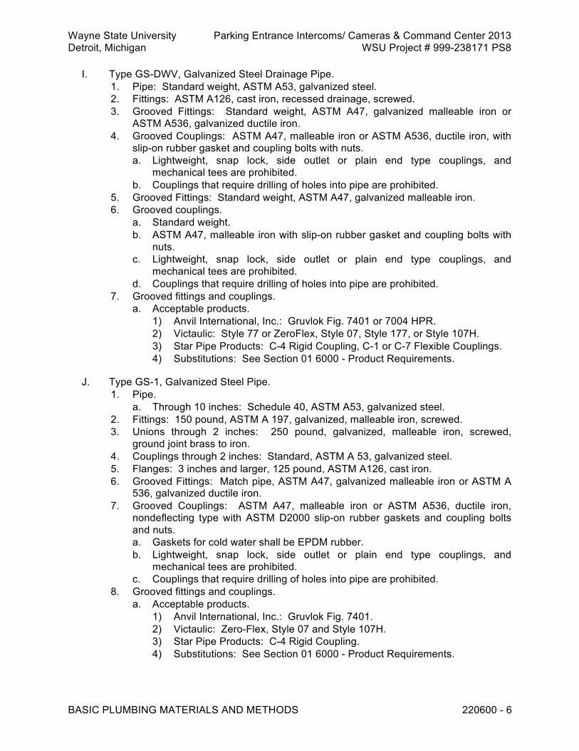
Wayne State University Parking Entrance Intercoms/ Cameras & Command Center 2013 Detroit, Michigan WSU Project # 999-238171 PS8
BASIC PLUMBING MATERIALS AND METHODS 220600 - 6
I. Type GS-DWV, Galvanized Steel Drainage Pipe. 1. Pipe: Standard weight, ASTM A53, galvanized steel. 2. Fittings: ASTM A126, cast iron, recessed drainage, screwed. 3. Grooved Fittings: Standard weight, ASTM A47, galvanized malleable iron or
ASTM A536, galvanized ductile iron. 4. Grooved Couplings: ASTM A47, malleable iron or ASTM A536, ductile iron, with
slip-on rubber gasket and coupling bolts with nuts. a. Lightweight, snap lock, side outlet or plain end type couplings, and
mechanical tees are prohibited. b. Couplings that require drilling of holes into pipe are prohibited.
5. Grooved Fittings: Standard weight, ASTM A47, galvanized malleable iron. 6. Grooved couplings.
a. Standard weight. b. ASTM A47, malleable iron with slip-on rubber gasket and coupling bolts with
nuts. c. Lightweight, snap lock, side outlet or plain end type couplings, and
mechanical tees are prohibited. d. Couplings that require drilling of holes into pipe are prohibited.
7. Grooved fittings and couplings. a. Acceptable products.
1) Anvil International, Inc.: Gruvlok Fig. 7401 or 7004 HPR. 2) Victaulic: Style 77 or ZeroFlex, Style 07, Style 177, or Style 107H. 3) Star Pipe Products: C-4 Rigid Coupling, C-1 or C-7 Flexible Couplings. 4) Substitutions: See Section 01 6000 - Product Requirements.
J. Type GS-1, Galvanized Steel Pipe. 1. Pipe.
a. Through 10 inches: Schedule 40, ASTM A53, galvanized steel. 2. Fittings: 150 pound, ASTM A 197, galvanized, malleable iron, screwed. 3. Unions through 2 inches: 250 pound, galvanized, malleable iron, screwed,
ground joint brass to iron. 4. Couplings through 2 inches: Standard, ASTM A 53, galvanized steel. 5. Flanges: 3 inches and larger, 125 pound, ASTM A126, cast iron. 6. Grooved Fittings: Match pipe, ASTM A47, galvanized malleable iron or ASTM A
536, galvanized ductile iron. 7. Grooved Couplings: ASTM A47, malleable iron or ASTM A536, ductile iron,
nondeflecting type with ASTM D2000 slip-on rubber gaskets and coupling bolts and nuts. a. Gaskets for cold water shall be EPDM rubber. b. Lightweight, snap lock, side outlet or plain end type couplings, and
mechanical tees are prohibited. c. Couplings that require drilling of holes into pipe are prohibited.
8. Grooved fittings and couplings. a. Acceptable products.
1) Anvil International, Inc.: Gruvlok Fig. 7401. 2) Victaulic: Zero-Flex, Style 07 and Style 107H. 3) Star Pipe Products: C-4 Rigid Coupling. 4) Substitutions: See Section 01 6000 - Product Requirements.
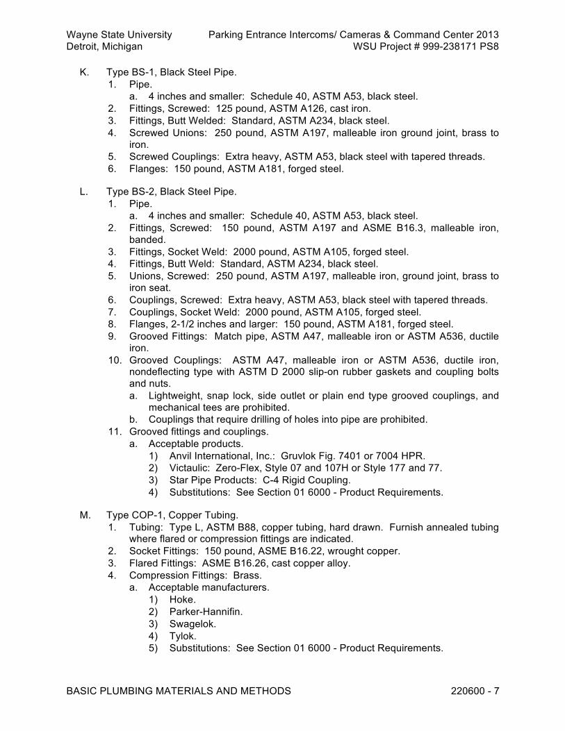
Wayne State University Parking Entrance Intercoms/ Cameras & Command Center 2013 Detroit, Michigan WSU Project # 999-238171 PS8
BASIC PLUMBING MATERIALS AND METHODS 220600 - 7
K. Type BS-1, Black Steel Pipe. 1. Pipe.
a. 4 inches and smaller: Schedule 40, ASTM A53, black steel. 2. Fittings, Screwed: 125 pound, ASTM A126, cast iron. 3. Fittings, Butt Welded: Standard, ASTM A234, black steel. 4. Screwed Unions: 250 pound, ASTM A197, malleable iron ground joint, brass to
iron. 5. Screwed Couplings: Extra heavy, ASTM A53, black steel with tapered threads. 6. Flanges: 150 pound, ASTM A181, forged steel.
L. Type BS-2, Black Steel Pipe. 1. Pipe.
a. 4 inches and smaller: Schedule 40, ASTM A53, black steel. 2. Fittings, Screwed: 150 pound, ASTM A197 and ASME B16.3, malleable iron,
banded. 3. Fittings, Socket Weld: 2000 pound, ASTM A105, forged steel. 4. Fittings, Butt Weld: Standard, ASTM A234, black steel. 5. Unions, Screwed: 250 pound, ASTM A197, malleable iron, ground joint, brass to
iron seat. 6. Couplings, Screwed: Extra heavy, ASTM A53, black steel with tapered threads. 7. Couplings, Socket Weld: 2000 pound, ASTM A105, forged steel. 8. Flanges, 2-1/2 inches and larger: 150 pound, ASTM A181, forged steel. 9. Grooved Fittings: Match pipe, ASTM A47, malleable iron or ASTM A536, ductile
iron. 10. Grooved Couplings: ASTM A47, malleable iron or ASTM A536, ductile iron,
nondeflecting type with ASTM D 2000 slip-on rubber gaskets and coupling bolts and nuts. a. Lightweight, snap lock, side outlet or plain end type grooved couplings, and
mechanical tees are prohibited. b. Couplings that require drilling of holes into pipe are prohibited.
11. Grooved fittings and couplings. a. Acceptable products.
1) Anvil International, Inc.: Gruvlok Fig. 7401 or 7004 HPR. 2) Victaulic: Zero-Flex, Style 07 and 107H or Style 177 and 77. 3) Star Pipe Products: C-4 Rigid Coupling. 4) Substitutions: See Section 01 6000 - Product Requirements.
M. Type COP-1, Copper Tubing. 1. Tubing: Type L, ASTM B88, copper tubing, hard drawn. Furnish annealed tubing
where flared or compression fittings are indicated. 2. Socket Fittings: 150 pound, ASME B16.22, wrought copper. 3. Flared Fittings: ASME B16.26, cast copper alloy. 4. Compression Fittings: Brass.
a. Acceptable manufacturers. 1) Hoke. 2) Parker-Hannifin. 3) Swagelok. 4) Tylok. 5) Substitutions: See Section 01 6000 - Product Requirements.

Wayne State University Parking Entrance Intercoms/ Cameras & Command Center 2013 Detroit, Michigan WSU Project # 999-238171 PS8
BASIC PLUMBING MATERIALS AND METHODS 220600 - 8
N. Type COP-3, Copper Tubing. 1. Tubing: Type K, ASTM B88, copper tubing, hard drawn. Concealed aboveground
tubing may be annealed. 2. Socket fittings: 150 pound, ASME B16.22, wrought copper.
O. Type COP-DWV, Copper Drainage Tubing. 1. Tubing: Type DWV, ASTM B306, copper drainage tube. 2. Fittings: ASME B16.29, wrought copper drainage type or ANSI B16.23, cast
brass drainage type. 2.2 MANUFACTURED UNITS
A. Mechanically Attached Fittings. 1. May be used instead of screwed or welded joints on black steel pipe sized 3
inches and smaller. 2. Qualified to ASME B31.1 and B31.3 codes, and meeting API 607. 3. Metal to metal seal. 4. Fitting body and swage rings manufactured from hot rolled micro alloyed 15V24
carbon steel conforming to ASTM A675. 5. Corrosion resistant coating. 6. Acceptable product.
a. Lokring, MAS-3000 Series. b. Substitutions: See Section 01 6000 - Product Requirements.
B. Pressure Gauges. 1. Standard, 6 inch, round gauge with cast aluminum case finished in dull black and
fitted with chrome plated ring, or stainless steel case and ring, graduations ranging from zero to twice minimum working pressure on line served, and gauge cock.
2. Include brass or steel siphon on pressure gauges for steam lines. 3. Equip pressure gauges installed on pumped lines with pulsation dampeners. 4. Acceptable products.
a. Ametek, U.S. Gauge Division: No. 5105-S. b. Ashcroft: No. 1010. c. Trerice: No. 600. d. Weiss Instruments: NF6S Series. e. Substitutions: See Section 01 6000 - Product Requirements.
C. Thermometers. 1. Standard cast aluminum case, with manufacturer's standard finish, and complete
with liquid filled tube and 9 inch indicating scale. 2. Scale and stem shall be completely adjustable. 3. Furnish brass thermometer wells for thermometers in services with temperatures
less than 350 degrees F. Others to be ANSI Type 18-8 stainless steel. 4. Acceptable products.
a. Ashcroft: Every Angle No. 200. b. Taylor: Multi-Angle No. 30E. c. Trerice: Adjustable Angle No. BX9. d. Weiss Instruments: Vari-Angle 9VS.

Wayne State University Parking Entrance Intercoms/ Cameras & Command Center 2013 Detroit, Michigan WSU Project # 999-238171 PS8
BASIC PLUMBING MATERIALS AND METHODS 220600 - 9
e. Substitutions: See Section 01 6000 - Product Requirements.
D. Electric Heat Tracing Systems. 1. Electrical heating cable.
a. Flat, flexible, electrical resistance, heater strips with electrically conductive core material between 2 copper bus strips, flexible, abrasion resistant, and electrically insulating outer sheath and wiring connections with end seals.
b. Electrical conductivity of core material shall decrease with increasing temperature.
c. Furnish and install heater strips suitable for operation at maximum maintenance temperature of 120 degrees F and maximum continuous exposure temperature of 185 degrees F.
d. Refer to drawings for operating voltage. e. Acceptable products.
1) Raychem: Chemelex Auto-Trace Type BTV. 2) Thermon: Type HSX/TSX. 3) Substitutions: See Section 01 6000 - Product Requirements.
2. Select circuit length to prevent inrush current at 0 degree F from exceeding circuit breaker rating.
3. Controls. a. Outdoor thermostat set at 40 degrees F complete with sensing bulb and
capillary tubing. b. Furnish each individual tracing circuit with pipe sensing thermostat and
control relay. 4. Control panel.
a. NEMA 12 enclosure housing main breaker, branch breakers, magnetic contactor, control transformer (if required), push buttons, selector switches, indicating and alarm lights, and alarm horn.
b. Enclosure to have flange mounted operator. c. Refer to drawings for contactor and breaker sizes.
5. Main breaker. a. 10 KA minimum interrupting, 480 VAC or 240 VAC, 3 pole, bolt-on type. b. Acceptable products.
1) General Electric: E150, Type TEB. 2) Square D: Types EH, FA, and IF. 3) Westinghouse: Types EB, EHD, and FD.
6. Branch breakers. a. 10 KA minimum interrupting, 240 VAC or 120 VAC, single pole, bolt-on type
having ground leakage interruption (30 MA trip) with auxiliary contact. b. Acceptable product.
1) Square D: Type QOB-EPD. 7. Magnetic contactor.
a. Industrial, heavy-duty, 600 VAC, 3 pole, electrically held type, with 100 percent resistance load rating, and one normally open and one normally closed contact, rated 5A at 102 VAC, for external use.
b. Acceptable products. 1) Allen-Bradley: Bulletin 500L. 2) Culter-Hammer: Series C-30. 3) Square D: Class 8903, Type S.

Wayne State University Parking Entrance Intercoms/ Cameras & Command Center 2013 Detroit, Michigan WSU Project # 999-238171 PS8
BASIC PLUMBING MATERIALS AND METHODS 220600 - 10
8. Control transformer. a. 50 VA minimum, sized to operate auxiliaries, and having 120 VAC secondary,
primary voltage indicated, and individually fused primary and secondary windings.
b. Acceptable products. 1) Allen-Bradley: Bulletin 1497. 2) Cutler-Hammer: Series C-340. 3) Square D: Class 9070, Type K.
9. Push buttons and selector switches. a. Heavy-duty, oiltight type, contact rated 10A continuous, 600 VAC maximum,
and having legend plate inscription indicated. b. Acceptable products.
1) Allen-Bradley: Bulletin 800T. 2) Cutler-Hammer: Series 10250-T. 3) Square D: Class 9001, Type K.
10. Indicating lights. a. Heavy-duty, oiltight type with 6 volt lamp, integral 120 to 6 VAC transformer,
push-to-test feature, color cap, and legend plate inscription as indicated. b. Acceptable products.
1) Allen-Bradley: Bulletin 800T. 2) Cutler-Hammer: Series 10250-T. 3) Square D: Class 9001, Type K.
11. Alarm light. a. Incandescent, enclosed and gasketed type with red glass globe and guard,
25 watt lamp, porcelain socket, and mounted invertedly on top of enclosure. b. Acceptable product.
1) Appleton: Stylemaster.
E. Strainers. 1. Bronze, cast iron, or cast steel strainers to match material of system in which
strainers are installed. Strainers tapped for installation of blowdown valve. Pressure rating equal to system's pressure rating.
2. Screen's free hole area: Twice internal area of pipe minimum. 3. Sizes 2 inches and smaller: Y type with threaded inlets and outlets. 4. Sizes 2-1/2 inches and larger: Basket and Y type with flanged inlets and outlets. 5. Furnish 3/4 inch blowdown valves on strainers size 4 inches and larger. 6. Screens for water service: Bronze or monel metal. Maximum openings of 0.033
inch for sizes 2 inches and smaller and 3/64 inch for sizes 2-1/2 inches and larger. 7. Screens for air or gas service: Stainless steel with maximum openings of 0.006
inch for sizes 2 inches and larger and 0.009 inch for sizes 2-1/2 inches and larger. 8. Acceptable manufacturers.
a. Mueller Steam Specialty. b. Spence. c. Spirax/Sarco. d. Substitutions: See Section 01 6000 - Product Requirements.
F. Floor and Wall Sleeve Materials. 1. Furnish and install sleeves for pipes penetrating building construction.
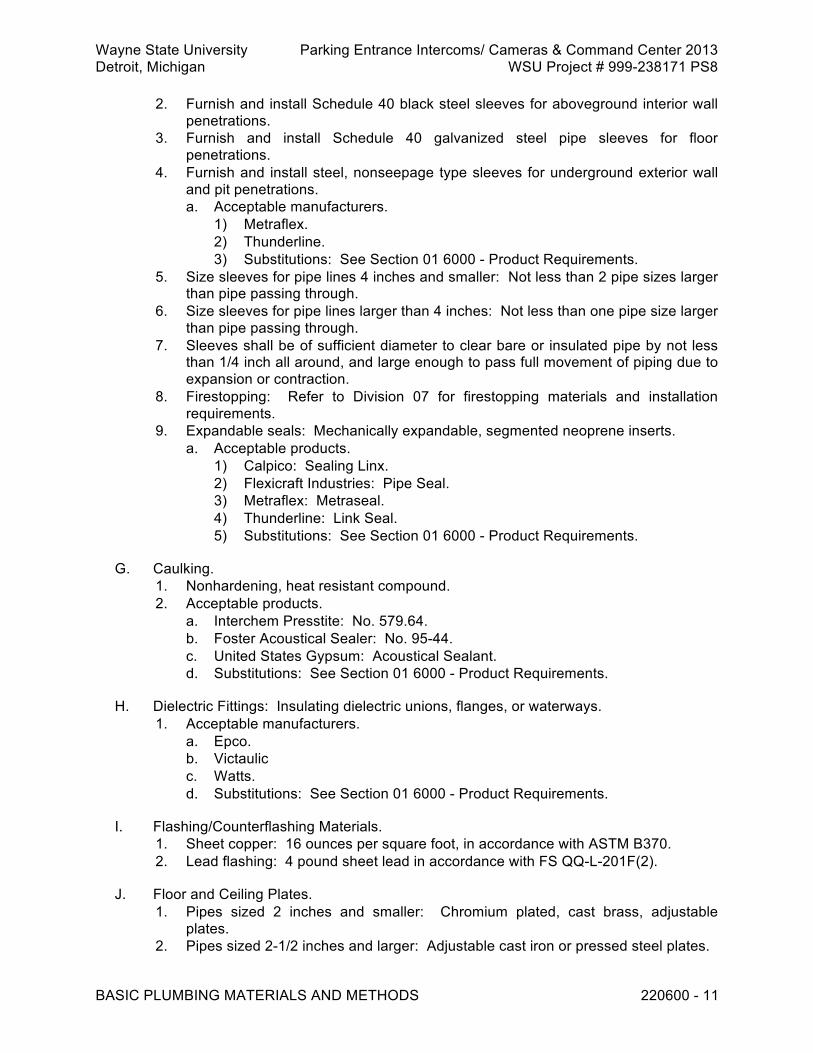
Wayne State University Parking Entrance Intercoms/ Cameras & Command Center 2013 Detroit, Michigan WSU Project # 999-238171 PS8
BASIC PLUMBING MATERIALS AND METHODS 220600 - 11
2. Furnish and install Schedule 40 black steel sleeves for aboveground interior wall penetrations.
3. Furnish and install Schedule 40 galvanized steel pipe sleeves for floor penetrations.
4. Furnish and install steel, nonseepage type sleeves for underground exterior wall and pit penetrations. a. Acceptable manufacturers.
1) Metraflex. 2) Thunderline. 3) Substitutions: See Section 01 6000 - Product Requirements.
5. Size sleeves for pipe lines 4 inches and smaller: Not less than 2 pipe sizes larger than pipe passing through.
6. Size sleeves for pipe lines larger than 4 inches: Not less than one pipe size larger than pipe passing through.
7. Sleeves shall be of sufficient diameter to clear bare or insulated pipe by not less than 1/4 inch all around, and large enough to pass full movement of piping due to expansion or contraction.
8. Firestopping: Refer to Division 07 for firestopping materials and installation requirements.
9. Expandable seals: Mechanically expandable, segmented neoprene inserts. a. Acceptable products.
1) Calpico: Sealing Linx. 2) Flexicraft Industries: Pipe Seal. 3) Metraflex: Metraseal. 4) Thunderline: Link Seal. 5) Substitutions: See Section 01 6000 - Product Requirements.
G. Caulking. 1. Nonhardening, heat resistant compound. 2. Acceptable products.
a. Interchem Presstite: No. 579.64. b. Foster Acoustical Sealer: No. 95-44. c. United States Gypsum: Acoustical Sealant. d. Substitutions: See Section 01 6000 - Product Requirements.
H. Dielectric Fittings: Insulating dielectric unions, flanges, or waterways. 1. Acceptable manufacturers.
a. Epco. b. Victaulic c. Watts. d. Substitutions: See Section 01 6000 - Product Requirements.
I. Flashing/Counterflashing Materials. 1. Sheet copper: 16 ounces per square foot, in accordance with ASTM B370. 2. Lead flashing: 4 pound sheet lead in accordance with FS QQ-L-201F(2).
J. Floor and Ceiling Plates. 1. Pipes sized 2 inches and smaller: Chromium plated, cast brass, adjustable
plates. 2. Pipes sized 2-1/2 inches and larger: Adjustable cast iron or pressed steel plates.

Wayne State University Parking Entrance Intercoms/ Cameras & Command Center 2013 Detroit, Michigan WSU Project # 999-238171 PS8
BASIC PLUMBING MATERIALS AND METHODS 220600 - 12
K. Flange Gaskets and Bolting. 1. Gasket, Type GASK1: Compressed, nonasbestos, synthetic fiber blend, suitable
for service, 1/16 inch thick. a. Acceptable manufacturers.
1) Gasket Resources, Inc. 2) Garlock: Blue-gard. 3) Klinger. 4) Substitutions: See Section 01 6000 - Product Requirements.
2. Bolting, Type BOLT1: Machine bolts in accordance with ASTM A 307, Grade B and hex nuts in accordance with ASTM A 563.
L. Pipe Thread Compounds. 1. Furnish and install compounds compatible with service, service temperature, and
pipe material specified for service. 2. Compounds for potable water shall be USDA and FDA approved. 3. Compounds containing lead are prohibited.
M. Copper Jointing Material. 1. Hard solder.
a. Meeting requirements of ASTM B 32. b. Alloy containing less than 0.2 percent lead. c. Minimum melting point: 400 degrees F. d. Acceptable products.
1) J.W. Harris: Bridgit. 2) Engelhard Corp.: Silvabrite 100. 3) Substitutions: See Section 01 6000 - Product Requirements.
2. Mechanical fittings. a. Conform to material and sizing requirements of ASME B16.18 or ASME
B16.22. b. EPDM O-rings. c. Acceptable product.
1) Ridgid/Viega: ProPress System. 2) Substitutions: See Section 01 6000 - Product Requirements.
PART 3 EXECUTION 3.1 INSTALLATION
A. Earthwork for Underground Systems. 1. Exclude excavation, shoring, and dewatering from this section.
B. Pipe Bedding. 1. For granular bedding, Class B.
a. Use material as specified in Section 31 0000. b. Spread and compact in accordance with Section 31 0000.
C. Initial Backfill. 1. Material, as specified in Section 31 0000. 2. Do not place around concrete for at least 24 hours after concrete placement.

Wayne State University Parking Entrance Intercoms/ Cameras & Command Center 2013 Detroit, Michigan WSU Project # 999-238171 PS8
BASIC PLUMBING MATERIALS AND METHODS 220600 - 13
3. Do not disturb or cause damage to fresh concrete. 4. Protect pipe and joints from disturbance. 5. Place in trenches after pipe is in place and tested. 6. Place within 10 feet of end of last pipe section laid. 7. Push material from filled end of trench into partially filled section of trench,
allowing material to roll down an incline onto covered pipe. 8. Do not push material over side of open trench, allowing clear fall onto partially
covered pipe. 9. Install from pipe bedding to 12 inches above top of highest pipe in trench after
compaction. 10. Spread and compact in accordance with Section 31 0000.
D. Exclude backfill from top of initial backfill to grade from this section.
E. Furnish and install bedding and initial backfill for existing pipe exposed during excavation.
F. Underground Pipe Corrosion Protection. 1. Mill wrap.
a. Pipe 3 inches and smaller, and in lengths greater than 300 linear feet. b. Pipe 4 inches and larger, and in lengths greater than 100 linear feet. c. Factory mill wrap pipe according to the following sequence.
1) Thoroughly machine clean pipe. 2) Apply uniform prime coat of coal tar pipeline primer. 3) Apply uniform coat, 3/32 inch thick, of plasticized pipeline enamel. 4) Spiral wrap fiberglass wrapper. 5) Apply uniform coat, 1/32 inch thick, of plasticized pipeline enamel. 6) Spiral wrap perforated pipeline felt wrapper. 7) Spiral wrap kraft paper wrapper. 8) Perform electrical holiday inspection test for flaw detection.
2. Tape wrap. a. Pipe 3 inches and smaller, and in lengths of 300 linear feet or less. b. Pipe 4 inches and larger, and in lengths of 100 linear feet or less. c. Read manufacturer's instructions before tape is applied.
1) Clean corroded pipe, then prime with primer recommended by tape or sheath manufacturer.
2) Apply tape under warm weather conditions to ensure proper adhesion and in accordance with manufacturer's instructions.
3) Spirally wrap pipe segments, fittings, valves, and connections. 4) Overlap, on successive wrapper passes, minimum of 1/2 width of tape. 5) Cover welded joints with 1 wrap prior to spiral wrapping. 6) Electrical holiday inspection is required for all types.
3. Hot tape wrap. a. For mill wrapped pipe, apply hot tape wrap to fittings and field joints,
compatible with millwrap bitumen, and suitable for specified ambient service conditions.
b. May be applied under all weather conditions in accordance with manufacturer's published instructions.
4. Pipe sheath.
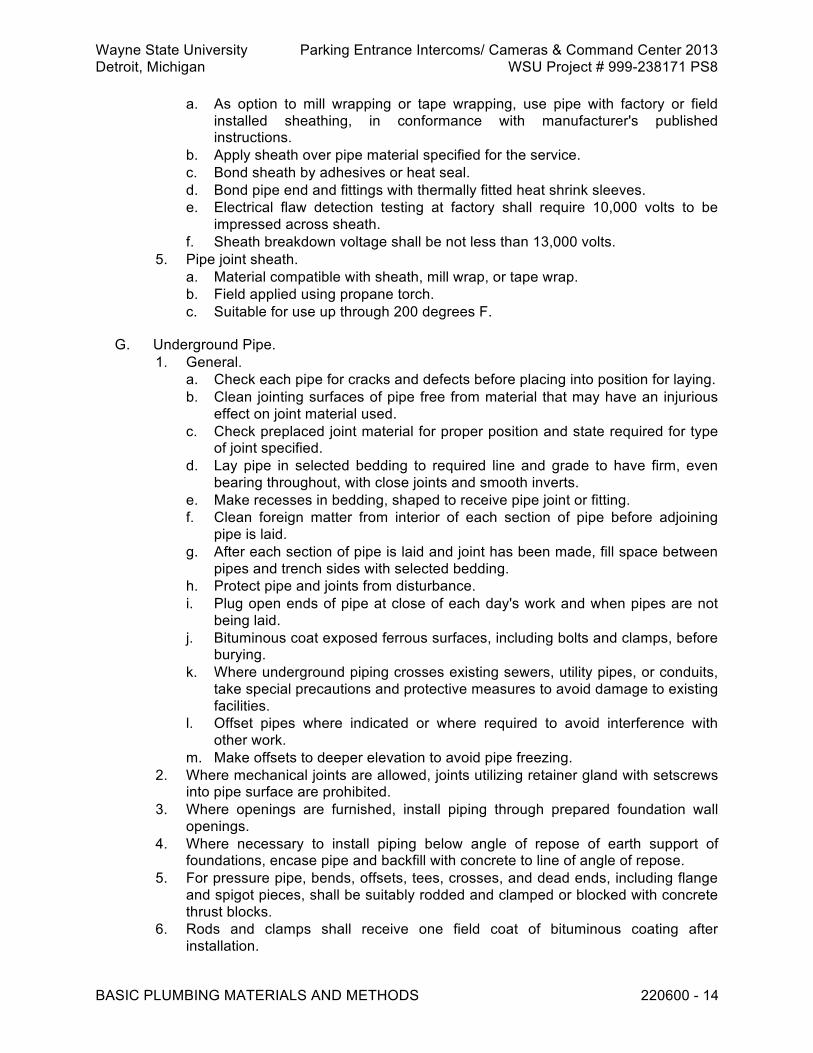
Wayne State University Parking Entrance Intercoms/ Cameras & Command Center 2013 Detroit, Michigan WSU Project # 999-238171 PS8
BASIC PLUMBING MATERIALS AND METHODS 220600 - 14
a. As option to mill wrapping or tape wrapping, use pipe with factory or field installed sheathing, in conformance with manufacturer's published instructions.
b. Apply sheath over pipe material specified for the service. c. Bond sheath by adhesives or heat seal. d. Bond pipe end and fittings with thermally fitted heat shrink sleeves. e. Electrical flaw detection testing at factory shall require 10,000 volts to be
impressed across sheath. f. Sheath breakdown voltage shall be not less than 13,000 volts.
5. Pipe joint sheath. a. Material compatible with sheath, mill wrap, or tape wrap. b. Field applied using propane torch. c. Suitable for use up through 200 degrees F.
G. Underground Pipe. 1. General.
a. Check each pipe for cracks and defects before placing into position for laying. b. Clean jointing surfaces of pipe free from material that may have an injurious
effect on joint material used. c. Check preplaced joint material for proper position and state required for type
of joint specified. d. Lay pipe in selected bedding to required line and grade to have firm, even
bearing throughout, with close joints and smooth inverts. e. Make recesses in bedding, shaped to receive pipe joint or fitting. f. Clean foreign matter from interior of each section of pipe before adjoining
pipe is laid. g. After each section of pipe is laid and joint has been made, fill space between
pipes and trench sides with selected bedding. h. Protect pipe and joints from disturbance. i. Plug open ends of pipe at close of each day's work and when pipes are not
being laid. j. Bituminous coat exposed ferrous surfaces, including bolts and clamps, before
burying. k. Where underground piping crosses existing sewers, utility pipes, or conduits,
take special precautions and protective measures to avoid damage to existing facilities.
l. Offset pipes where indicated or where required to avoid interference with other work.
m. Make offsets to deeper elevation to avoid pipe freezing. 2. Where mechanical joints are allowed, joints utilizing retainer gland with setscrews
into pipe surface are prohibited. 3. Where openings are furnished, install piping through prepared foundation wall
openings. 4. Where necessary to install piping below angle of repose of earth support of
foundations, encase pipe and backfill with concrete to line of angle of repose. 5. For pressure pipe, bends, offsets, tees, crosses, and dead ends, including flange
and spigot pieces, shall be suitably rodded and clamped or blocked with concrete thrust blocks.
6. Rods and clamps shall receive one field coat of bituminous coating after installation.
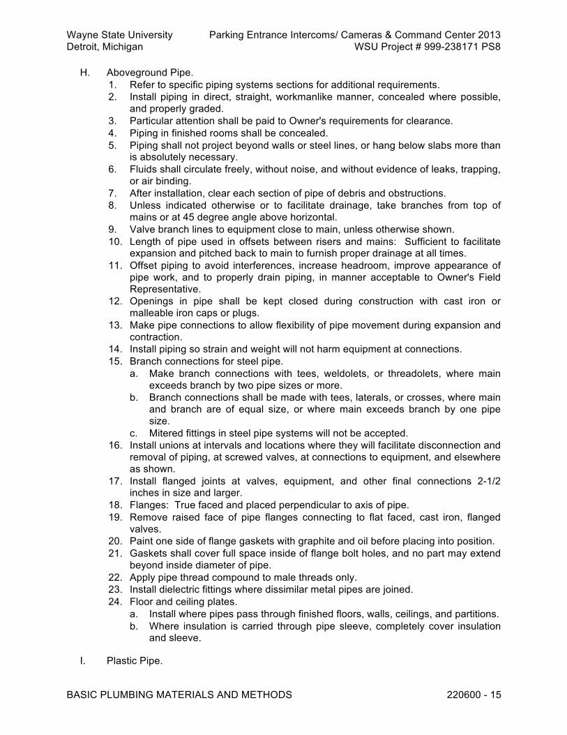
Wayne State University Parking Entrance Intercoms/ Cameras & Command Center 2013 Detroit, Michigan WSU Project # 999-238171 PS8
BASIC PLUMBING MATERIALS AND METHODS 220600 - 15
H. Aboveground Pipe. 1. Refer to specific piping systems sections for additional requirements. 2. Install piping in direct, straight, workmanlike manner, concealed where possible,
and properly graded. 3. Particular attention shall be paid to Owner's requirements for clearance. 4. Piping in finished rooms shall be concealed. 5. Piping shall not project beyond walls or steel lines, or hang below slabs more than
is absolutely necessary. 6. Fluids shall circulate freely, without noise, and without evidence of leaks, trapping,
or air binding. 7. After installation, clear each section of pipe of debris and obstructions. 8. Unless indicated otherwise or to facilitate drainage, take branches from top of
mains or at 45 degree angle above horizontal. 9. Valve branch lines to equipment close to main, unless otherwise shown. 10. Length of pipe used in offsets between risers and mains: Sufficient to facilitate
expansion and pitched back to main to furnish proper drainage at all times. 11. Offset piping to avoid interferences, increase headroom, improve appearance of
pipe work, and to properly drain piping, in manner acceptable to Owner's Field Representative.
12. Openings in pipe shall be kept closed during construction with cast iron or malleable iron caps or plugs.
13. Make pipe connections to allow flexibility of pipe movement during expansion and contraction.
14. Install piping so strain and weight will not harm equipment at connections. 15. Branch connections for steel pipe.
a. Make branch connections with tees, weldolets, or threadolets, where main exceeds branch by two pipe sizes or more.
b. Branch connections shall be made with tees, laterals, or crosses, where main and branch are of equal size, or where main exceeds branch by one pipe size.
c. Mitered fittings in steel pipe systems will not be accepted. 16. Install unions at intervals and locations where they will facilitate disconnection and
removal of piping, at screwed valves, at connections to equipment, and elsewhere as shown.
17. Install flanged joints at valves, equipment, and other final connections 2-1/2 inches in size and larger.
18. Flanges: True faced and placed perpendicular to axis of pipe. 19. Remove raised face of pipe flanges connecting to flat faced, cast iron, flanged
valves. 20. Paint one side of flange gaskets with graphite and oil before placing into position. 21. Gaskets shall cover full space inside of flange bolt holes, and no part may extend
beyond inside diameter of pipe. 22. Apply pipe thread compound to male threads only. 23. Install dielectric fittings where dissimilar metal pipes are joined. 24. Floor and ceiling plates.
a. Install where pipes pass through finished floors, walls, ceilings, and partitions. b. Where insulation is carried through pipe sleeve, completely cover insulation
and sleeve.
I. Plastic Pipe.

Wayne State University Parking Entrance Intercoms/ Cameras & Command Center 2013 Detroit, Michigan WSU Project # 999-238171 PS8
BASIC PLUMBING MATERIALS AND METHODS 220600 - 16
1. Make up joints and install plastic piping in accordance with manufacturer's instructions.
2. Use fittings for offsets and changes in direction. 3. Bending of pipe and mitered end pipe joints are prohibited. 4. Furnish adapters where connections to metallic pipe are required.
J. Cast Iron Soil Pipes. 1. Install cast iron soil pipe in accordance with CISPI Cast Iron Soil Pipe and Fittings
Handbook, except where otherwise specified. 2. Join no-hub cast iron soil pipe with couplings in accordance with manufacturer's
instructions. 3. Lead for oakum and lead packed joints shall not recess more than 1/8 inch below
rim of hub.
K. Mechanical Fittings for Copper Tubing. 1. In accordance with manufacturer's instructions. 2. Cut tubing square and deburr ends. 3. Fully insert tubing into fitting and mark at shoulder of fitting. 4. Check fitting alignment against mark to ensure full engagement. 5. Press joint using manufacturer approved tool.
L. Pipe Welding. 1. Perform steel pipe welding in accordance with ASME B31.9 and applicable
requirements of authorities having jurisdiction. 2. Pipe ends requiring butt welds.
a. Ream free of burrs and bevel 37 degrees, plus or minus 2 degrees. b. Center pipe ends and locate 1/8 inch apart, plus or minus 1/32 inch. c. Before applying welding beads, make not less than 4 equally spaced tack
welds between pipe end. d. Clean each bead thoroughly before starting the following pass.
3. Remove welds found to be defective. a. Replace defective welds with nondefective welds to ensure compliance with
Contract provisions without additional cost to Owner. b. Peening of defective welds or applying additional beads to defective welds
are not acceptable methods of repair. 4. Furnish fire blankets to protect building structure, services, materials, and
equipment. 5. Furnish and install protective curtains or shields to protect personnel from
welder's flash.
M. Grooved Joints. 1. Install grooved fittings and couplings as recommended by manufacturer. 2. Use only those grooved couplings specified. Substitution of other model, style,
size, or rating of couplings or fittings is prohibited. 3. Roll grooving of piping is prohibited for use in galvanized steel pipe systems.
N. Strainers. 1. Install strainers in accordance with manufacturer's instructions. At tapped
openings, install nipple and general service ball valve.

Wayne State University Parking Entrance Intercoms/ Cameras & Command Center 2013 Detroit, Michigan WSU Project # 999-238171 PS8
BASIC PLUMBING MATERIALS AND METHODS 220600 - 17
O. Pressure Gauges and Thermometers. 1. Install pressure gauges and thermometer well connections in fittings. Drilling and
tapping of pipe wall for connections is prohibited. 2. Locate gauges and thermometers in accordance with manufacturer's instructions
and in visible locations for easy reading from normal operating levels.
P. Electric Heat Tracing. 1. Install electric heat tracing cable in accordance with manufacturer's instructions
and Owner's Field Representative reviewed installation drawings. 2. Route cable to prevent crushing, fraying, tearing, breaking, or shearing under
forces and motions expected during installation and operation. 3. Straighten kinks in cable prior to installation. 4. Tape cable to ensure continuous contact between cable and pipe. 5. Terminate leads in junction boxes. Locate and seal junction boxes to prevent
entry of moisture. Furnish one junction box for each piping system. 6. Electrical power supply is specified under Division 26. 7. Limit maximum cable circuit length so starting inrush current at 0 degree F does
not exceed 20 amperes circuit breaker rating.
Q. Sleeves and Seals. 1. Set sleeves in concrete work in position before concrete is poured, and maintain
them in position until concrete is set. 2. Holes for sleeves in existing concrete shall be cored. 3. Sleeves through walls shall extend minimum of 1/2 inch beyond wall flange. 4. Install floor sleeves for exposed risers or equipment services flush with ceiling,
with planed square ends extending 2 inches above finished floor. 5. Extend floor sleeves for pipe risers in finished areas to extend to uniform height of
not more than 2 inches above finished floor. 6. Pipes located within pipe shafts and chases do not require sleeves. 7. Where indicated, seal space between pipe and sleeves in exterior walls,
watertight, by packing with oakum and caulking with lead. 8. For underground wall and pit penetrations, and on grade floor penetrations, and
where indicated, seal space between pipe sleeves watertight with mechanically expandable, segmented neoprene inserts. Install in accordance with manufacturer's instructions. Bituminous coat all exposed bolt heads.
9. Caulking. a. Caulk pipes passing through interior partitions and walls, airtight around their
circumference on both sides of partition. b. Apply caulking between pipe sleeve and exterior surface of pipe or pipe
insulation. c. Apply caulking beads in accordance with manufacturer's instructions. d. Unless manufacturer's instructions state otherwise, make sealant beads not
thinner than 1/8 inch nor thicker than 3/8 inch. e. Use of general purpose, oil base, caulking compounds, of putties and of
plaster will not be accepted for sealing of pipe penetrations.
R. Flashings/Counterflashings. 1. Size flashing flange minimum of 6 inches larger than outside diameter of pipe, or
minimum of 24 inches square, and extend sleeves up around pipes to height of not less than 10 inches above roof line, unless otherwise indicated.

Wayne State University Parking Entrance Intercoms/ Cameras & Command Center 2013 Detroit, Michigan WSU Project # 999-238171 PS8
BASIC PLUMBING MATERIALS AND METHODS 220600 - 18
2. Install flashing/counterflashing. 3. For plumbing vent pipe flashing, extend sleeve up inside bottom of either inverted
hub connection or reviewed and accepted vent fitting. 4. Where copper flashing is indicated, solder flange and sleeve watertight. 5. Install copper counterflashing with stainless steel draw bands.
S. Welding to Building Structure. 1. Welding to building structure is not allowed, unless otherwise specified or
specifically accept by Owner's Field Representative. 2. If so specified or accepted, comply with following requirements.
a. Unless otherwise noted, welding and workmanship shall be governed by AISC Specifications for the Design, Fabrication and Erection of Structural Steel for Buildings in conjunction with AWS D1.1.
b. Allowable stress in field applied welds using E70 Series and A36 steel. 1) Tension or compression : Same as base metal. 2) Shear: 15,800 pounds per square inch.
c. Surfaces to be welded: Free from loose slag, scale, rust, grease, paint, or other foreign material.
d. Before welding, painted surfaces shall have paint removed to expose clean steel surface.
e. Special attention is called to requirement that maximum size of fillet weld that may be assumed in design of connection shall ensure that stresses in adjacent base material do not exceed allowable value for this material.
f. Weld transmitting calculated stress: Not less than 3 inches in length, and intermittent welds shall not be less than 2 inches in length.
g. Do not apply welds to flanges of tension members perpendicular to direction of stress.
h. Turn side and end fillet welds around corners for minimum length of twice nominal size of weld.
i. To ensure compliance, detail shall be indicated on shop drawings. j. Length of end returns is not be included in calculated weld length. k. Welding or other operation involving use of flame, arcs, or sparking devices
will not be allowed without written permission of Owner's representative. l. Welds found be in nonconformance to requirements of AWS D1.1 shall be
repaired or replaced according to Workmanship section of AWS D1.1 without cost to Owner.
T. General Pipe Testing Requirements. 1. Prior to acceptance of work, test completed piping systems, in accordance with
applicable governing codes, and in presence of Owner's Representative. a. Furnish necessary equipment and materials, and make necessary test
connections required to execute tests. b. Make tests before piping surfaces are concealed or insulated. c. Use standard piping plugs, caps, valves, and blind flanges for sealing off
piping for testing. d. Removal of system component, including plugs and caps, to ascertain
whether or not test media has reached all parts of system if purging or vent valves are not installed during construction, may be required by Owner's Representative.

Wayne State University Parking Entrance Intercoms/ Cameras & Command Center 2013 Detroit, Michigan WSU Project # 999-238171 PS8
BASIC PLUMBING MATERIALS AND METHODS 220600 - 19
e. Remove components from piping systems during testing whenever component may sustain damage due to test pressure or test media.
f. After completion of test, reinstall component and reapply test at component pressure rating.
g. Check system components and valves for functional operation under system test pressure.
2. Pressure tests, when specified, shall be carried out in accordance with ASME B31.9.
3. Take necessary precautions to vent expansive force of compressed air trapped during high pressure hydrostatic testing to preclude injury and damage.
4. If testing demonstrates leakage. a. Determine source(s) of leakage, repair or replace defective materials and
workmanship, and retest installation until specified requirements are complied with.
b. Replace leaking gasket joints with undamaged gaskets and flange bolting. c. Destroy removed gaskets and bolting.
5. For hydrostatic tests: Use only potable water. 6. Pneumatic testing.
a. Use compressed air, carbon dioxide, or nitrogen, unless otherwise specified or accepted.
b. Preliminary testing at 5 psi shall require swabbing joints with soap solution and subsequent observation for bubbles.
7. Upon completion of work, but before final acceptance, operate systems for period of two days, for purpose of testing and satisfying requirements, when directed by Owner's Representative.
8. Prepare and maintain test records of all piping systems tests. a. List Owner and Contractor personnel present, dates, test gauge identification
numbers, ambient temperatures, pressure ranges, rates of pressure drop, and leakage rates.
b. Deliver two record copies of acceptance tests to Owner after acceptance. 9. Refer to Sections listed under heading, Related Sections, for requirements
specific to individual piping systems.
U. Flushing and Purging General Requirements. 1. Install temporary and permanent piping, equipment, and materials required for
flushing and purging work. 2. Flushing and purging of add-on system into existing system is strictly prohibited. 3. After flushing and purging, all valves and strainers shall be removed and cleaned
of debris before replacing. 4. Coordinate cleaning of connections to existing systems through Owner's
Representative. 5. Flush and purge systems after successful pressure testing.
3.2 FIELD QUALITY CONTROL
A. Check that pressure, temperature, and flow measuring devices are placed in correct locations. Make modifications to ensure compliance.

Wayne State University Parking Entrance Intercoms/ Cameras & Command Center 2013 Detroit, Michigan WSU Project # 999-238171 PS8
BASIC PLUMBING MATERIALS AND METHODS 220600 - 20
B. Check scale ranges of individual instruments. Expected normal reading shall be near middle of scale. Replace instruments not conforming to this requirement.
C. Verify that piping systems have been flushed and filled.
D. Check valve packings. Adjust or replace leaking valve packings.
E. Verify piping alignment at flexible connections or expansion joints, in hot and cold condition. Correct misalignment, where joints are found to squirm.
END OF SECTION 220600

Wayne State University Parking Entrance Intercoms/ Cameras & Command Center 2013 Detroit, Michigan WSU Project # 999-238171 PS8
PLUMBING PIPING INSULATION 220720 - 1
SECTION 220720 - PLUMBING PIPING INSULATION PART 1 GENERAL 1.1 RELATED REQUIREMENTS
A. Section 22 0513 - Common Work Results for Plumbing.
B. Section 22 0600 - Basic Plumbing Materials and Methods.
C. Section 22 1008 - Hangers and Supports for Plumbing Piping and Equipment. 1.2 REFERENCE STANDARDS
A. ASTM C547 - Standard Specification for Mineral Fiber Pipe Insulation.
B. ASTM E84 - Standard Test Method for Surface Burning Characteristics of Building Materials.
C. ASTM E96 - Standard Test Methods for Water Vapor Transmission of Materials. 1.3 SUBMITTALS
A. See Section 01 3000 – Administrative Requirements, for submittal procedures.
B. For Information. 1. Product data.
a. Each product and component. 1.4 WARRANTY
A. See Section 01 7800 – Closeout Submittals, for additional warranty requirements. 1.5 SCHEDULES
A. Plumbing Piping Insulation. 1. Sanitary drainage, outdoor.
a. Type PP-1 with FF-1, or PP-1 with FF-3, all plus JJ-1. b. Thickness: 2 inches on all size pipe.
2. Domestic cold water, indoor. a. Type PP-1 with FF-1, or PP-1 with FF-3. Vapor barrier required. b. Thickness: 1 inch on all size pipe.
3. Domestic cold water, outdoor. a. Type PP-1 with FF-1, or PP-1 with FF-3, all plus JJ-1. Vapor barrier required. b. Thickness: 2 inches on all size pipe.
4. Domestic hot water, indoor.

Wayne State University Parking Entrance Intercoms/ Cameras & Command Center 2013 Detroit, Michigan WSU Project # 999-238171 PS8
PLUMBING PIPING INSULATION 220720 - 2
a. Type PP-1 with FF-2, or PP-1 with FF-3. b. Thickness: 1 inch on all size pipe.
5. Rainwater conductors, nonvertical portions and vertical leaders (maximum 7 feet) at roof drains. a. Type PP-1 with FF-1 or PP-1 with FF-3. Vapor barrier required. b. Thickness: 1 inch on all size pipe.
6. Underside of roof drains. a. Type FF-5. Vapor barrier required. b. Thickness: 1 inch.
PART 2 PRODUCTS 2.1 SYSTEM DESCRIPTION
A. Drawings indicate equipment locations, related layouts, and general design of systems specified under Division 22.
B. Include thermal insulation for scheduled systems.
C. Unless otherwise specified or indicated, insulate surfaces in accordance with insulation schedules specified.
2.2 MATERIALS
A. General. 1. Include insulating materials having maximum flame spread rating of 25 and
maximum smoke developed rating of 50, when tested in accordance with ASTM E84.
2. Preformed fiberglass pipe insulation, in accordance with ASTM C547. 3. Insulating materials UL labeled. 4. Adhesives fire resistant in their dry states and UL listed.
B. Pipe Insulation. 1. Type PP-1, rigid, molded fiberglass.
a. Minimum density: 3-1/2 pounds per cubic foot. b. Thermal conductivity: Not more than 0.26 Btu per hour, per square foot, per
degree F, per inch, at mean temperature of 75 degrees F. c. Jacket: Factory applied vapor barrier, with self-sealing laps. d. Laminate: White kraft paper facing exterior. e. Glass fiber reinforcing scrim. f. Aluminum foil facing, with vapor permeance of not more than 0.02 perm when
measured in accordance with ASTM E96, Procedure A. g. Acceptable products.
1) Knauf, Fiber Glass ASJ-SSL. 2) Manson, Alley K-SSL. 3) Manville, Micro-Loc 650 AP-T. 4) Owens-Corning, Fiberglas 25 ASJ-SSL-II. 5) Substitutions: See Section 01 6000 - Product Requirements.

Wayne State University Parking Entrance Intercoms/ Cameras & Command Center 2013 Detroit, Michigan WSU Project # 999-238171 PS8
PLUMBING PIPING INSULATION 220720 - 3
C. Fittings Insulation. 1. Type FF-1, fiberglass blanket or preformed segmented.
a. Density: 1 pound per cubic foot. b. Thermal conductivity: Not more than 0.28 Btu per hour, per square foot, per
degree F, per inch, at mean temperature of 75 degrees F. c. Vapor barrier coating.
2. Type FF-2, fiberglass blanket or preformed segmented. a. Density: 1 pound per cubic foot. b. Thermal conductivity: Not more than 0.28 Btu per hour, per square foot, per
degree F, per inch, at mean temperature of 75 degrees F. 3. Type FF-3, premolded, one-piece, PVC insulated fitting covers.
a. Factory precut fiberglass insulation segments. b. Flexible, self-extinguishing PVC cover: Flame spread classification, not more
than 25. Fuel contribution, not more than 25, as tested in accordance with ASTM E84.
c. Acceptable products. 1) Accessible Products, 300 Series Thermazip. 2) Ceel Company, Ceel-Tite 300. 3) Coverite, S-800. 4) Knauf, Proto. 5) Manville, Zeston. 6) Substitutions: See Section 01 6000 - Product Requirements.
4. Type FF-5. a. Insulating cement and a final layer of vapor barrier coating with embedded
fiberglass cloth.
D. Jacketing. 1. Type JJ-1, 3003 or 5005 aluminum roll.
a. Protect insulating material. Integral vapor barrier coating on insulation side. b. Round jacketing, minimum thickness, 0.016 inch.
1) Locked longitudinal seams. 2) Butt circumferential joints. 3) Butt straps and stainless steel draw bands. 4) Include butt straps with high temperature resistant weatherproof sealant.
c. Rectangular jacketing, minimum thickness, 0.032 inch. d. Acceptable products.
1) Childers, Lock-On, Ell-Jacs and Tee-Jacs. 2) Pabco, Surefit. 3) Substitutions: See Section 01 6000 - Product Requirements.
E. Cements, Adhesives, and Coatings. 1. Insulating and finishing cement.
a. Acceptable products. 1) Celotex, MW-1. 2) Pabco, Pabcote. 3) Fibrex, FBX Superkote. 4) Substitutions: See Section 01 6000 - Product Requirements.
2. Lap adhesive and finish coating for nonvapor barrier applications. a. Acceptable products.

Wayne State University Parking Entrance Intercoms/ Cameras & Command Center 2013 Detroit, Michigan WSU Project # 999-238171 PS8
PLUMBING PIPING INSULATION 220720 - 4
1) Childers, CP-50A. 2) Foster, 30-04. 3) Marathon, 102. 4) Substitutions: See Section 01 6000 - Product Requirements.
3. Vapor barrier lap adhesive and surfacing adhesive. a. Acceptable products.
1) Childers, CP-82. 2) Foster, 85-20. 3) Marathon, 225. 4) Substitutions: See Section 01 6000 - Product Requirements.
4. Vapor barrier coatings. a. Acceptable products.
1) Marathon, 501. 2) Childers, CP-30 or CP-32. 3) Foster, 30-35. 4) Substitutions: See Section 01 6000 - Product Requirements.
PART 3 EXECUTION 3.1 INSTALLATION
A. General Requirements. 1. Install to present a neat, clean appearance. 2. Apply only after surfaces have been cleaned, inspected, and tested. 3. Apply neatly, tightly, with unbroken lengths, and with ends of sections firmly
butted together. 4. At joints, lap insulating jackets and cement in position. 5. Sectional covering shall be uniform. 6. Where required material thickness is not available, layer insulation, staggering
butt joints. 7. Do not dilute surface finishes and adhesives. 8. Apply surface finishes and adhesives in accordance with manufacturer's
instructions. 9. Do not apply sealing coats until volatiles have dissipated, and until cements and
adhesives have thoroughly dried. 10. Unless otherwise specified, do not apply second or multiple coats until previous
coats have thoroughly dried. 11. Do not use flame or spark producing equipment in areas where adhesives,
mastics, sealants, or coatings containing volatiles are stored or being applied. 12. Maintain integrity of vapor barriers. Do not use fasteners to secure vapor barrier
insulation, which penetrate or damage vapor barrier. 13. Butt insulation to building construction and to angle iron stops. Where vapor seals
or similar facings are required, extend and seal to building construction or angle. 14. Surfaces to be insulated shall be considered concealed where located in furred
spaces or above suspended ceilings, other work shall be considered exposed. 15. Restore to original likeness existing insulation damaged during progress of the
work.
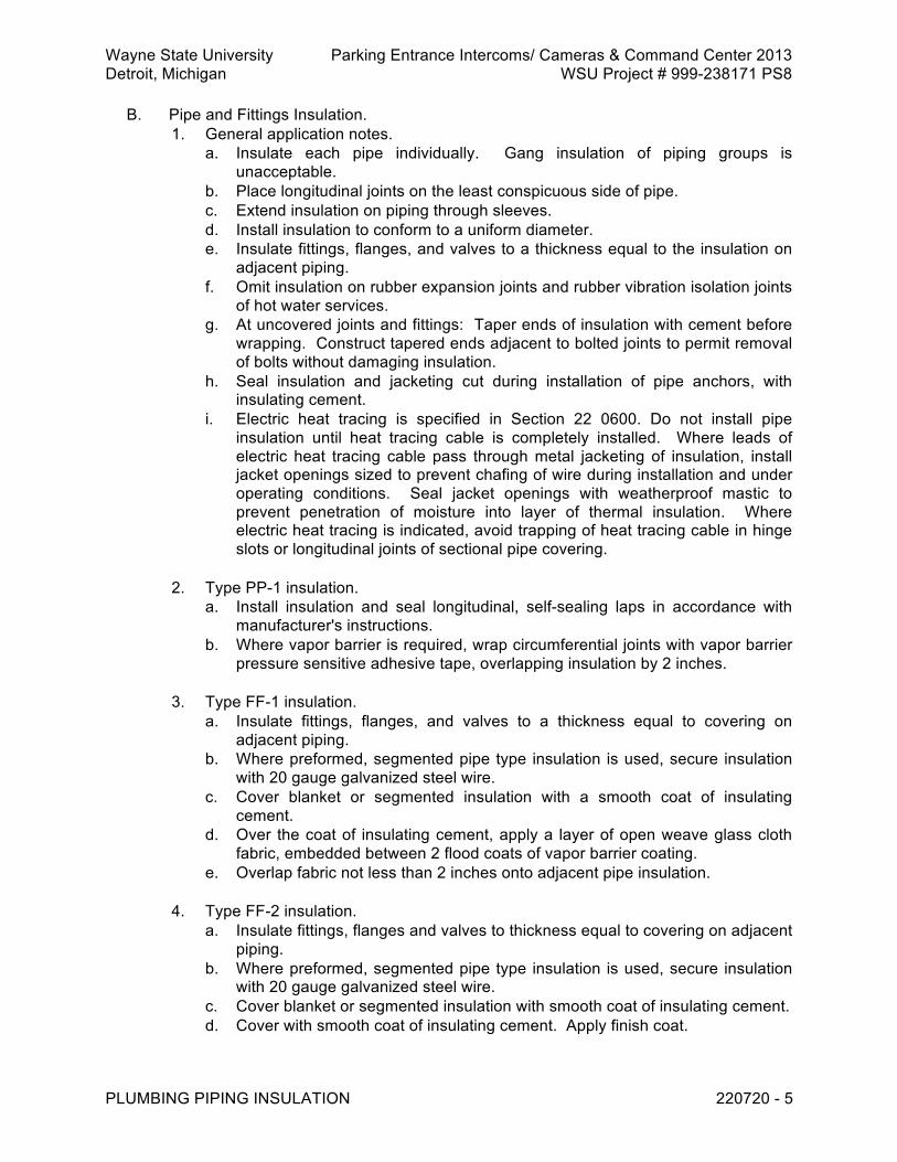
Wayne State University Parking Entrance Intercoms/ Cameras & Command Center 2013 Detroit, Michigan WSU Project # 999-238171 PS8
PLUMBING PIPING INSULATION 220720 - 5
B. Pipe and Fittings Insulation. 1. General application notes.
a. Insulate each pipe individually. Gang insulation of piping groups is unacceptable.
b. Place longitudinal joints on the least conspicuous side of pipe. c. Extend insulation on piping through sleeves. d. Install insulation to conform to a uniform diameter. e. Insulate fittings, flanges, and valves to a thickness equal to the insulation on
adjacent piping. f. Omit insulation on rubber expansion joints and rubber vibration isolation joints
of hot water services. g. At uncovered joints and fittings: Taper ends of insulation with cement before
wrapping. Construct tapered ends adjacent to bolted joints to permit removal of bolts without damaging insulation.
h. Seal insulation and jacketing cut during installation of pipe anchors, with insulating cement.
i. Electric heat tracing is specified in Section 22 0600. Do not install pipe insulation until heat tracing cable is completely installed. Where leads of electric heat tracing cable pass through metal jacketing of insulation, install jacket openings sized to prevent chafing of wire during installation and under operating conditions. Seal jacket openings with weatherproof mastic to prevent penetration of moisture into layer of thermal insulation. Where electric heat tracing is indicated, avoid trapping of heat tracing cable in hinge slots or longitudinal joints of sectional pipe covering.
2. Type PP-1 insulation.
a. Install insulation and seal longitudinal, self-sealing laps in accordance with manufacturer's instructions.
b. Where vapor barrier is required, wrap circumferential joints with vapor barrier pressure sensitive adhesive tape, overlapping insulation by 2 inches.
3. Type FF-1 insulation.
a. Insulate fittings, flanges, and valves to a thickness equal to covering on adjacent piping.
b. Where preformed, segmented pipe type insulation is used, secure insulation with 20 gauge galvanized steel wire.
c. Cover blanket or segmented insulation with a smooth coat of insulating cement.
d. Over the coat of insulating cement, apply a layer of open weave glass cloth fabric, embedded between 2 flood coats of vapor barrier coating.
e. Overlap fabric not less than 2 inches onto adjacent pipe insulation. 4. Type FF-2 insulation.
a. Insulate fittings, flanges and valves to thickness equal to covering on adjacent piping.
b. Where preformed, segmented pipe type insulation is used, secure insulation with 20 gauge galvanized steel wire.
c. Cover blanket or segmented insulation with smooth coat of insulating cement. d. Cover with smooth coat of insulating cement. Apply finish coat.

Wayne State University Parking Entrance Intercoms/ Cameras & Command Center 2013 Detroit, Michigan WSU Project # 999-238171 PS8
PLUMBING PIPING INSULATION 220720 - 6
5. Type FF-3 insulation. a. Where insulation system requires a vapor barrier: Seal edges of cover with
vapor barrier coating. Wrap circumferential joints with vapor barrier pressure sensitive adhesive tape. Overlap adjacent pipe insulation by at least 2 inches.
b. Where insulation system does not require vapor barrier: Apply adhesive. Staple, tack fasten, or tape cover to adjacent pipe covering as recommended by manufacturer. Overlap adjacent pipe insulation by at least 2 inches.
6. Type FF-5 insulation.
a. Insulate underside of roof drains with insulating cement. b. Finish with fiberglass cloth embedded in vapor barrier coating.
C. Jacketing. 1. Type JJ-1.
a. Install round jacketing and attach butt straps and draw bands in accordance with manufacturer's instructions.
b. Lap rectangular jacketing not less than 2 inches on longitudinal and transverse joints. Lap top jacketing over side jacketing. Seal joints with manufacturer's standard weather and heat resistant sealant. Attach jacketing with stainless steel sheet metal screws and lead washers, or galvanized angle iron hoops.
END OF SECTION 220720

Wayne State University Parking Entrance Intercoms/ Cameras & Command Center 2013 Detroit, Michigan WSU Project # 999-238171 PS8
HANGERS AND SUPPORTS FOR PLUMBING PIPING 221008-1
SECTION 221008 - HANGERS AND SUPPORTS FOR PLUMBING PIPING PART 1 GENERAL 1.1 REFERENCE STANDARDS
A. AISC (COMM) - Commentary on the Specification for Structural Steel Buildings--Allowable Stress Design and Plastic Design.
B. ASME B31.1 - Power Piping ; 2007 (ANSI/ASME B31.1).
C. ASTM A 575 - Standard Specification for Steel Bars, Carbon, Merchant Quality, M Grades ; 1996 (Reapproved 2007).
D. AWS D1.1/D1.1 M - Structural Welding Code - Steel ; 2008.
E. MSS SP-58 - Pipe Hangers and Supports - Materials, Design and Manufacture.
F. MSS SP-69 - Pipe Hangers and Supports - Selection and Application. 1.2 SUBMITTALS
A. See Section 01 3000 – Administrative Requirements, for submittal procedures.
B. For Review. 1. Shop drawings.
a. Pipe hanger and support installation details, including details and locations of seismic or sway bracing, pipe anchors, and anchor bracing.
b. Include dimensioned location and method of attachment to building structure. c. Where pipe hangers cannot be hung from building structure, submit proposed
method of installing additional structural steel that connects to the building structure.
1.3 QUALITY ASSURANCE
A. Qualifications. 1. Supplemental steel welding procedures, in accordance with section, Qualification,
of AWS D1.1. 2. Only welders who have successfully passed examination for this class of work
shall be employed to execute structural strength welds. 3. Examination shall have been within the past six months, unless welder has been
making this type of weld after passing test within two years, as specified under qualification procedures of AWS D1.1.
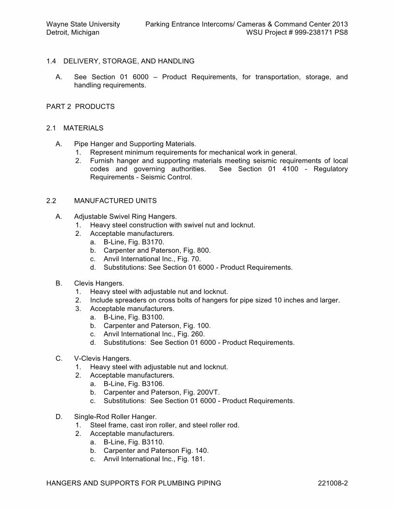
Wayne State University Parking Entrance Intercoms/ Cameras & Command Center 2013 Detroit, Michigan WSU Project # 999-238171 PS8
HANGERS AND SUPPORTS FOR PLUMBING PIPING 221008-2
1.4 DELIVERY, STORAGE, AND HANDLING
A. See Section 01 6000 – Product Requirements, for transportation, storage, and handling requirements.
PART 2 PRODUCTS 2.1 MATERIALS
A. Pipe Hanger and Supporting Materials. 1. Represent minimum requirements for mechanical work in general. 2. Furnish hanger and supporting materials meeting seismic requirements of local
codes and governing authorities. See Section 01 4100 - Regulatory Requirements - Seismic Control.
2.2 MANUFACTURED UNITS
A. Adjustable Swivel Ring Hangers. 1. Heavy steel construction with swivel nut and locknut. 2. Acceptable manufacturers.
a. B-Line, Fig. B3170. b. Carpenter and Paterson, Fig. 800. c. Anvil International Inc., Fig. 70. d. Substitutions: See Section 01 6000 - Product Requirements.
B. Clevis Hangers. 1. Heavy steel with adjustable nut and locknut. 2. Include spreaders on cross bolts of hangers for pipe sized 10 inches and larger. 3. Acceptable manufacturers.
a. B-Line, Fig. B3100. b. Carpenter and Paterson, Fig. 100. c. Anvil International Inc., Fig. 260. d. Substitutions: See Section 01 6000 - Product Requirements.
C. V-Clevis Hangers. 1. Heavy steel with adjustable nut and locknut. 2. Acceptable manufacturers.
a. B-Line, Fig. B3106. b. Carpenter and Paterson, Fig. 200VT. c. Substitutions: See Section 01 6000 - Product Requirements.
D. Single-Rod Roller Hanger. 1. Steel frame, cast iron roller, and steel roller rod. 2. Acceptable manufacturers.
a. B-Line, Fig. B3110. b. Carpenter and Paterson Fig. 140. c. Anvil International Inc., Fig. 181.
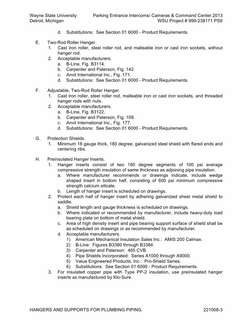
Wayne State University Parking Entrance Intercoms/ Cameras & Command Center 2013 Detroit, Michigan WSU Project # 999-238171 PS8
HANGERS AND SUPPORTS FOR PLUMBING PIPING 221008-3
d. Substitutions: See Section 01 6000 - Product Requirements.
E. Two-Rod Roller Hanger. 1. Cast iron roller, steel roller rod, and malleable iron or cast iron sockets, without
hanger rod. 2. Acceptable manufacturers.
a. B-Line, Fig. B3114. b. Carpenter and Paterson, Fig. 142. c. Anvil International Inc., Fig. 171. d. Substitutions: See Section 01 6000 - Product Requirements.
F. Adjustable, Two-Rod Roller Hanger. 1. Cast iron roller, steel roller rod, malleable iron or cast iron sockets, and threaded
hanger rods with nuts. 2. Acceptable manufacturers.
a. B-Line, Fig. B3122. b. Carpenter and Paterson, Fig. 109. c. Anvil International Inc., Fig. 177. d. Substitutions: See Section 01 6000 - Product Requirements.
G. Protection Shields. 1. Minimum 18 gauge thick, 180 degree, galvanized steel shield with flared ends and
centering ribs.
H. Preinsulated Hanger Inserts. 1. Hanger inserts consist of two 180 degree segments of 100 psi average
compressive strength insulation of same thickness as adjoining pipe insulation. a. Where manufacturer recommends or drawings indicate, include wedge
shaped insert in bottom half, consisting of 600 psi minimum compressive strength calcium silicate.
b. Length of hanger insert is scheduled on drawings. 2. Protect each half of hanger insert by adhering galvanized sheet metal shield to
saddle. a. Shield length and gauge thickness is scheduled on drawings. b. Where indicated or recommended by manufacturer, include heavy-duty load
bearing plate on bottom of metal shield. c. Area of high density insert and pipe bearing support surface of shield shall be
as scheduled on drawings or as recommended by manufacturer. d. Acceptable manufacturers.
1) American Mechanical Insulation Sales Inc.: AMIS 200 Calmax. 2) B-Line: Figures B3380 through B3384. 3) Carpenter and Paterson: 465 CVB. 4) Pipe Shields Incorporated: Series A1000 through A9000. 5) Value Engineered Products, Inc.: Pro-Shield Series. 6) Substitutions: See Section 01 6000 - Product Requirements.
3. For insulated copper pipe with Type PP-2 insulation, use preinsulated hanger inserts as manufactured by Klo-Sure.
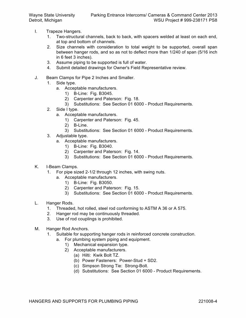
Wayne State University Parking Entrance Intercoms/ Cameras & Command Center 2013 Detroit, Michigan WSU Project # 999-238171 PS8
HANGERS AND SUPPORTS FOR PLUMBING PIPING 221008-4
I. Trapeze Hangers. 1. Two-structural channels, back to back, with spacers welded at least on each end,
at top and bottom of channels. 2. Size channels with consideration to total weight to be supported, overall span
between hanger rods, and so as not to deflect more than 1/240 of span (5/16 inch in 6 feet 3 inches).
3. Assume piping to be supported is full of water. 4. Submit detailed drawings for Owner's Field Representative review.
J. Beam Clamps for Pipe 2 Inches and Smaller. 1. Side type.
a. Acceptable manufacturers. 1) B-Line: Fig. B3045. 2) Carpenter and Paterson: Fig. 18. 3) Substitutions: See Section 01 6000 - Product Requirements.
2. Side I type. a. Acceptable manufacturers.
1) Carpenter and Paterson: Fig. 45. 2) B-Line. 3) Substitutions: See Section 01 6000 - Product Requirements.
3. Adjustable type. a. Acceptable manufacturers.
1) B-Line: Fig. B3040. 2) Carpenter and Paterson: Fig. 14. 3) Substitutions: See Section 01 6000 - Product Requirements.
K. I-Beam Clamps. 1. For pipe sized 2-1/2 through 12 inches, with swing nuts.
a. Acceptable manufacturers. 1) B-Line: Fig. B3050. 2) Carpenter and Paterson: Fig. 15. 3) Substitutions: See Section 01 6000 - Product Requirements.
L. Hanger Rods. 1. Threaded, hot rolled, steel rod conforming to ASTM A 36 or A 575. 2. Hanger rod may be continuously threaded. 3. Use of rod couplings is prohibited.
M. Hanger Rod Anchors. 1. Suitable for supporting hanger rods in reinforced concrete construction.
a. For plumbing system piping and equipment. 1) Mechanical expansion type. 2) Acceptable manufacturers.
(a) Hilti: Kwik Bolt TZ. (b) Power Fasteners: Power-Stud + SD2. (c) Simpson Strong Tie: Strong-Bolt. (d) Substitutions: See Section 01 6000 - Product Requirements.

Wayne State University Parking Entrance Intercoms/ Cameras & Command Center 2013 Detroit, Michigan WSU Project # 999-238171 PS8
HANGERS AND SUPPORTS FOR PLUMBING PIPING 221008-5
PART 3 EXECUTION 3.1 INSTALLATION
A. Install hanger and supporting materials in accordance with specified requirements, and in accordance with seismic requirements dictated by local codes and governing authorities. 1. Submit typical details and locations for review.
B. C-clamps without retainer clips and heat-treated spring steel clips that bite into building steel are prohibited as means of fastening pipe hangers to building structure.
C. Clamps that result in eccentric loads (twisting moments) on structural members of building, except for piping sized 2 inches and smaller, are also prohibited.
D. Support piping from building structural frame, not from roof deck, permanent metal forms for concrete floors, concrete slab (unless indicated otherwise), or from other pipe, duct, or equipment.
E. Install hangers for nonvertical conductors, sized to accommodate future installation of 1 inch minimum insulation. 1. Hanger rods shall be long enough to allow lowering of hangers by 1 inch during
insulation installation.
F. Contractor's attention is directed to drawing details and building structural framing layout that may require hanger spacing more frequently than spacings shown in table below. 1. Loading at any support point shall not exceed 1000 pounds, unless specifically
indicated otherwise. Screwed or welded steel pipe (liquid or vapor)
Pipe Size Maximum Hanger Spacing Minimum Rod Size 1/2 to 1 inch 8 feet 3/8 inch 1-1/4 through 2 inches 10 feet 3/8 inch 2-1/2 to 3 inches 12 feet 1/2 inch 4 inches 12 feet 5/8 inch 6 inches 12 feet 3/4 inch 8 and 12 inches 12 feet 7/8 inch
Grooved end steel pipe (liquid or vapor)
Pipe Size Maximum Hanger Spacing Minimum Rod Size 1/2 to 1 inch 8 feet 3/8 inch 1-1/4 through 2 inches 10 feet 3/8 inch 2-1/2 to 3 inches 12 feet 1/2 inch 4 inches 12 feet 5/8 inch 6 inches 12 feet 3/4 inch
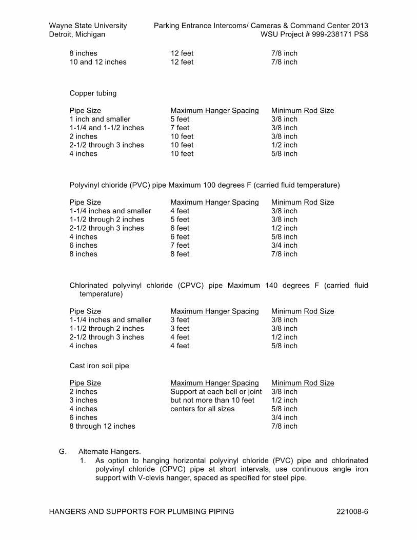
Wayne State University Parking Entrance Intercoms/ Cameras & Command Center 2013 Detroit, Michigan WSU Project # 999-238171 PS8
HANGERS AND SUPPORTS FOR PLUMBING PIPING 221008-6
8 inches 12 feet 7/8 inch 10 and 12 inches 12 feet 7/8 inch
Copper tubing
Pipe Size Maximum Hanger Spacing Minimum Rod Size 1 inch and smaller 5 feet 3/8 inch 1-1/4 and 1-1/2 inches 7 feet 3/8 inch 2 inches 10 feet 3/8 inch 2-1/2 through 3 inches 10 feet 1/2 inch 4 inches 10 feet 5/8 inch
Polyvinyl chloride (PVC) pipe Maximum 100 degrees F (carried fluid temperature)
Pipe Size Maximum Hanger Spacing Minimum Rod Size 1-1/4 inches and smaller 4 feet 3/8 inch 1-1/2 through 2 inches 5 feet 3/8 inch 2-1/2 through 3 inches 6 feet 1/2 inch 4 inches 6 feet 5/8 inch 6 inches 7 feet 3/4 inch 8 inches 8 feet 7/8 inch
Chlorinated polyvinyl chloride (CPVC) pipe Maximum 140 degrees F (carried fluid
temperature)
Pipe Size Maximum Hanger Spacing Minimum Rod Size 1-1/4 inches and smaller 3 feet 3/8 inch 1-1/2 through 2 inches 3 feet 3/8 inch 2-1/2 through 3 inches 4 feet 1/2 inch 4 inches 4 feet 5/8 inch
Cast iron soil pipe
Pipe Size Maximum Hanger Spacing Minimum Rod Size 2 inches Support at each bell or joint 3/8 inch 3 inches but not more than 10 feet 1/2 inch 4 inches centers for all sizes 5/8 inch 6 inches 3/4 inch 8 through 12 inches 7/8 inch
G. Alternate Hangers. 1. As option to hanging horizontal polyvinyl chloride (PVC) pipe and chlorinated
polyvinyl chloride (CPVC) pipe at short intervals, use continuous angle iron support with V-clevis hanger, spaced as specified for steel pipe.
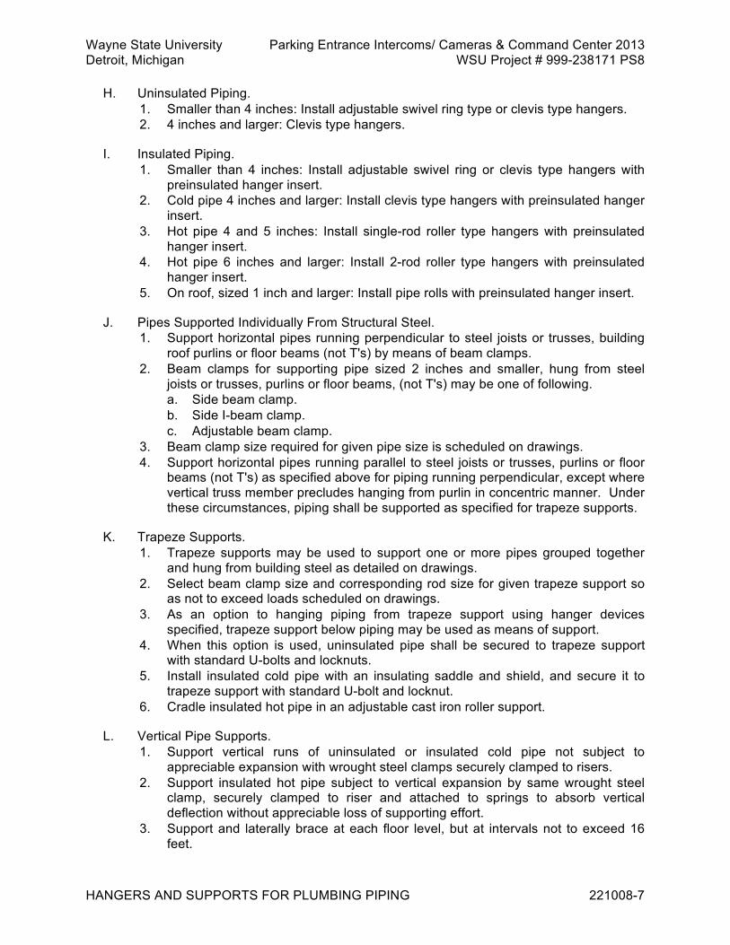
Wayne State University Parking Entrance Intercoms/ Cameras & Command Center 2013 Detroit, Michigan WSU Project # 999-238171 PS8
HANGERS AND SUPPORTS FOR PLUMBING PIPING 221008-7
H. Uninsulated Piping. 1. Smaller than 4 inches: Install adjustable swivel ring type or clevis type hangers. 2. 4 inches and larger: Clevis type hangers.
I. Insulated Piping. 1. Smaller than 4 inches: Install adjustable swivel ring or clevis type hangers with
preinsulated hanger insert. 2. Cold pipe 4 inches and larger: Install clevis type hangers with preinsulated hanger
insert. 3. Hot pipe 4 and 5 inches: Install single-rod roller type hangers with preinsulated
hanger insert. 4. Hot pipe 6 inches and larger: Install 2-rod roller type hangers with preinsulated
hanger insert. 5. On roof, sized 1 inch and larger: Install pipe rolls with preinsulated hanger insert.
J. Pipes Supported Individually From Structural Steel. 1. Support horizontal pipes running perpendicular to steel joists or trusses, building
roof purlins or floor beams (not T's) by means of beam clamps. 2. Beam clamps for supporting pipe sized 2 inches and smaller, hung from steel
joists or trusses, purlins or floor beams, (not T's) may be one of following. a. Side beam clamp. b. Side I-beam clamp. c. Adjustable beam clamp.
3. Beam clamp size required for given pipe size is scheduled on drawings. 4. Support horizontal pipes running parallel to steel joists or trusses, purlins or floor
beams (not T's) as specified above for piping running perpendicular, except where vertical truss member precludes hanging from purlin in concentric manner. Under these circumstances, piping shall be supported as specified for trapeze supports.
K. Trapeze Supports. 1. Trapeze supports may be used to support one or more pipes grouped together
and hung from building steel as detailed on drawings. 2. Select beam clamp size and corresponding rod size for given trapeze support so
as not to exceed loads scheduled on drawings. 3. As an option to hanging piping from trapeze support using hanger devices
specified, trapeze support below piping may be used as means of support. 4. When this option is used, uninsulated pipe shall be secured to trapeze support
with standard U-bolts and locknuts. 5. Install insulated cold pipe with an insulating saddle and shield, and secure it to
trapeze support with standard U-bolt and locknut. 6. Cradle insulated hot pipe in an adjustable cast iron roller support.
L. Vertical Pipe Supports. 1. Support vertical runs of uninsulated or insulated cold pipe not subject to
appreciable expansion with wrought steel clamps securely clamped to risers. 2. Support insulated hot pipe subject to vertical expansion by same wrought steel
clamp, securely clamped to riser and attached to springs to absorb vertical deflection without appreciable loss of supporting effort.
3. Support and laterally brace at each floor level, but at intervals not to exceed 16 feet.

Wayne State University Parking Entrance Intercoms/ Cameras & Command Center 2013 Detroit, Michigan WSU Project # 999-238171 PS8
HANGERS AND SUPPORTS FOR PLUMBING PIPING 221008-8
M. Where necessary for proper system functioning, brace piping and supports against reaction sway and vibration.
N. For concentrated loads, e.g., valves, reduce allowable span proportionately.
O. Vertical risers shall be supported independently of connected horizontal piping whenever practical, with fixed or spring supports at base and at intervals to accommodate system range of load and thermal conditions, and shall be guided for lateral stability. 1. Only one rigid support shall be installed for risers subjected to expansion at
approximately 1/3 point from top, unless otherwise indicated. 2. For horizontal piping contiguous to moving risers, two supports nearest to riser
shall be spring supports, unless otherwise indicated.
P. After piping systems have been installed, tested, and placed in satisfactory operation, firmly tighten hanger rod nut and jam nut and upset threads to prevent the movement of fasteners.
Q. Welding to Building Structure. 1. Welding to building structure is not allowed, unless otherwise specified or
specifically accepted by Owner's Field Representative 2. If so specified or accepted, comply with following requirements.
a. Unless otherwise noted, welding and workmanship shall be governed by AISC Specifications for the Design, Fabrication and Erection of Structural Steel for Buildings in conjunction with AWS D1.1.
b. Allowable stresses in field applied welds using E70 Series and A36 steel. 1) Tension or compression, same as base metal.
(a) Shear, 15,800 pounds per square inch.
R. Surfaces to be welded shall be free from loose slag, scale, rust, grease, paint, or other foreign material.
S. Before welding, painted surfaces shall have paint removed to expose clean steel surface. 1. Special attention is called to requirement that maximum size of fillet weld that may
be assumed in design of connection shall ensure that stresses in adjacent base material do not exceed allowable value for this material.
T. No welds transmitting calculated stress shall be less than 3 inches in length, and no intermittent welds shall be less than 2 inches in length.
U. No welds shall be applied to flanges of tension members perpendicular to direction of stress.
V. Turn side and end fillet welds around corners for minimum length of twice nominal size of weld.
W. Length of end returns is not to be included in calculated weld length.
X. No welding or other operation involving use of flame, arcs, or sparking devices will be allowed without written permission of Owner's Field Representative.

Wayne State University Parking Entrance Intercoms/ Cameras & Command Center 2013 Detroit, Michigan WSU Project # 999-238171 PS8
HANGERS AND SUPPORTS FOR PLUMBING PIPING 221008-9
Y. Welds found to be in nonconformance to requirements of AWS D1.1 shall be repaired or replaced according to workmanship section of AWS D1.1 at no cost to Owner.
END OF SECTION 221008
Wayne State University Parking Entrance Intercoms/ Cameras & Command Center 2013 Detroit, Michigan WSU Project # 999-238171 PS8
PLUMBING SYSTEMS AND SPECIALTIES 221010-1
SECTION 221010 - PLUMBING SYSTEMS AND SPECIALTIES PART 1 GENERAL 1.1 RELATED REQUIREMENTS
A. Division 03, Concrete
B. Division 07, Thermal and Moisture Protection.
C. Section 22 0513 - Common Work Results for Plumbing.
D. Section 22 0600 - Basic Plumbing Materials and Methods.
E. Section 22 0720 - Plumbing Insulation.
F. Division 31, Earthwork. 1.2 REFERENCE STANDARDS
A. ASSE 1013 - Reduced Pressure Principle Backflow Preventers and Reduced Pressure Fire Protection Principle Backflow Preventers ; 2005 (ANSI/ASSE 1013).
B. ASSE 1016 - Performance Requirements for Automatic Compensating Valves for Individual Showers and Tub/Shower Combinations ; 2005.
C. ASTM A48/A 48M - Standard Specification for Gray Iron Castings ; 2003.
D. ASTM B370 - Standard Specification for Copper Sheet and Strip for Building Construction ; 2003.
E. ASTM C32 - Standard Specification for Sewer and Manhole Brick (Made from Clay or Shale) ; 2009.
F. ASTM C139 - Standard Specification for Concrete Masonry Units for Construction of Catch Basins and Manholes ; 2005.
G. ASTM C270 - Standard Specification for Mortar for Unit Masonry ; 2007a.
H. ASTM C478 - Standard Specification for Precast Reinforced Concrete Manhole Sections ; 2007.
I. ASTM D 448 - Standard Classification for Sizes of Aggregate for Road and Bridge Construction.
J. AWWA C651 - Disinfecting Water Mains ; 2005 (ANSI/AWWA C651).
K. FS QQ-L-201 - Lead Sheet ; Revision F, 1965, and Amendment 2, 1970.

Wayne State University Parking Entrance Intercoms/ Cameras & Command Center 2013 Detroit, Michigan WSU Project # 999-238171 PS8
PLUMBING SYSTEMS AND SPECIALTIES 221010-2
L. PDI-WH 201 - Water Hammer Arresters ; 2006.
M. IAPMO PS 80-2006 - International Association of Plumbing and Mechanical Officials (IAPMO) Material and Property Standard for Grease Interceptors and Clarifiers
N. PEI RP 100 - Recommended Practices for Installation of Underground Liquid Storage Systems.
O. UL 58 - Standard for Steel Underground Tanks for Flammable and Combustible Liquids.
P. UL 1746 - Standard for External Corrosion Protection Systems for Steel Underground Storage Tanks.
Q. SSPC-SP 6 - Specification for Commercial Blast Cleaning 1.3 SUBMITTALS
A. Refer to Section 01 3000 – for submittal procedures.
B. For Information. 1. Product data.
a. Water pressure regulating valve.
C. For Closeout. 1. Project Record Documents. 2. Certificates.
a. PDI Standard WH 201 Certification of water hammer absorber. 3. Test Reports.
a. Potable Water System Disinfection Report. b. Backflow Prevention Device Test Report.
1.4 QUALITY ASSURANCE
A. Quality control provisions of Division 01, General Requirements, apply to this Section.
B. Reviews and acceptance, except as required for field installation, field applications, and field tests shall be obtained before delivery of items of material, equipment, or systems to project site.
C. Manufacturer’s Qualifications: Manufacturer regularly engaged, for past 5 years, in manufacture of underground protected steel gravity grease interceptor of similar type to that specified.
D. Installer's Qualifications: 1. Installer regularly engaged, for past 5 years, in installation of underground
protected steel gravity grease interceptors, oil/water separators, or steel storage tanks of similar type to that specified.
2. Employ persons trained for installation of underground protected steel gravity grease interceptors, oil/water separators, or steel storage tanks.
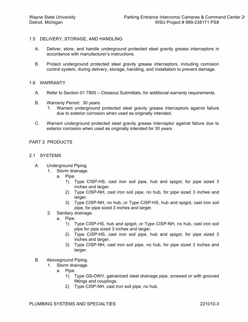
Wayne State University Parking Entrance Intercoms/ Cameras & Command Center 2013 Detroit, Michigan WSU Project # 999-238171 PS8
PLUMBING SYSTEMS AND SPECIALTIES 221010-3
1.5 DELIVERY, STORAGE, AND HANDLING
A. Deliver, store, and handle underground protected steel gravity grease interceptors in accordance with manufacturer’s instructions.
B. Protect underground protected steel gravity grease interceptors, including corrosion control system, during delivery, storage, handling, and installation to prevent damage.
1.6 WARRANTY
A. Refer to Section 01 7800 – Closeout Submittals, for additional warranty requirements.
B. Warranty Period: 30 years. 1. Warrant underground protected steel gravity grease interceptors against failure
due to exterior corrosion when used as originally intended.
C. Warrant underground protected steel gravity grease interceptor against failure due to exterior corrosion when used as originally intended for 30 years.
PART 2 PRODUCTS 2.1 SYSTEMS
A. Underground Piping. 1. Storm drainage.
a. Pipe. 1) Type CISP-HS, cast iron soil pipe, hub and spigot, for pipe sized 3
inches and larger. 2) Type CISP-NH, cast iron soil pipe, no hub, for pipe sized 3 inches and
larger. 3) Type CISP-NH, no hub, or Type CISP-HS, hub and spigot, cast iron soil
pipe, for pipe sized 3 inches and larger. 2. Sanitary drainage.
a. Pipe. 1) Type CISP-HS, hub and spigot, or Type CISP-NH, no hub, cast iron soil
pipe for pipe sized 3 inches and larger. 2) Type CISP-HS, cast iron soil pipe, hub and spigot, for pipe sized 3
inches and larger. 3) Type CISP-NH, cast iron soil pipe, no hub, for pipe sized 3 inches and
larger.
B. Aboveground Piping. 1. Storm drainage.
a. Pipe. 1) Type GS-DWV, galvanized steel drainage pipe, screwed or with grooved
fittings and couplings. 2) Type CISP-NH, cast iron soil pipe, no hub.

Wayne State University Parking Entrance Intercoms/ Cameras & Command Center 2013 Detroit, Michigan WSU Project # 999-238171 PS8
PLUMBING SYSTEMS AND SPECIALTIES 221010-4
3) Type CISP-HS, cast iron soil pipe, hub and spigot. 4) Type PVC, polyvinyl chloride pipe or Type PVC-DWV, polyvinyl chloride
drainage pipe, socket welded. 2. Sanitary drainage and vents.
a. Pipe. 1) Type COP-DWV, copper drainage tubing with soldered joints using hard
solder. 2) Type GS-DWV, galvanized steel drainage pipe, screwed. 3) Type CISP-NH, cast iron soil pipe, no hub. 4) Type CISP-HS, cast iron soil pipe, hub and spigot.
3. Cold water. a. Pipe.
1) Type COP-1, copper tubing for pipe sized 2 inches and smaller. 2) Type GS-1, galvanized steel pipe for pipe sized 2-1/2 inches and larger. 3) Type CPVC, chlorinated polyvinyl chloride pipe.
b. Joints. 1) Copper: Soldered, using hard solder. 2) Galvanized steel.
(a) Screwed and flanged using Type GASK2 gasketing and Type BOLT1 bolting.
(b) Grooved end type fittings and couplings. 3) Plastic (CPVC).
(a) Solvent welded or screwed for pipe sized 2 inches and smaller. (b) Solvent welded or flanged for pipe sized 2-1/2 inches and larger. (c) Use Type GASK2 gasketing and Type BOLT1 bolting.
c. Valves: Type GSV-1, general service valves. 4. Hot water.
a. Pipe. 1) Type COP-1, copper tubing for pipe sized 2 inches and smaller. 2) Type GS-1, galvanized steel pipe for pipe sized 2-1/2 inches and larger. 3) Type CPVC, chlorinated polyvinyl chloride pipe.
b. Joints. 1) Copper: Soldered, using hard solder. 2) Galvanized steel.
(a) Screwed and flanged using Type GASK1 gasketing and Type BOLT1 bolting.
(b) Grooved end type fittings and couplings. 3) Plastic (CPVC).
(a) Solvent welded or screwed for pipe sized 2 inches and smaller. (b) Solvent welded or flanged for pipe sized 2-1/2 inches and larger. (c) Use Type GASK1 gasketing and Type BOLT1 bolting.
c. Valves: Type GSV-1, general service valves. 5. Miscellaneous drain, waste, and vents.
a. Pipe. 1) Type GS-DWV, galvanized steel drainage pipe. 2) Type COP-DWV, copper drainage tubing.

Wayne State University Parking Entrance Intercoms/ Cameras & Command Center 2013 Detroit, Michigan WSU Project # 999-238171 PS8
PLUMBING SYSTEMS AND SPECIALTIES 221010-5
2.2 MANUFACTURED UNITS
A. Manhole or catch basin frames, covers, and grates: Cast iron, in accordance with ASTM A 48, Class 35. Completely coat ferrous metal surfaces with bituminous or coal tar epoxy coating. Frames shall include anchor bolts and bolt holes, and covers with lettering identifying service. Seating faces on covers, grates, and frames shall be machine finished. Covers and grates shall not rock or tilt. 1. Manhole or catch basin frames, covers and grates.
a. Type MH-1: Heavy-duty, round type with neoprene gasket and bolted lid. 1) Acceptable manufacturers.
(a) East Jordan Iron Works, No. 1045 PT. (b) Neenah, R-1915-G-Type L or R-1916-D. (c) Vulcan Foundry. (d) Substitutions: See Section 01 6000 - Product Requirements.
B. Miscellaneous Underground Materials. 1. Epoxy bonding compound.
a. Two-component epoxy-modified-polysulphide adhesive. b. Initial curing shall be accomplished within 48 hours at temperatures as low as
40 degrees F. c. Acceptable manufacturers.
1) Copolymer Chemicals, Crete-tac. 2) Emerson and Cuming (W.R. Grace), Cryovac. 3) Master Builders (American Metaseal), Meta-crete Gel. 4) Substitutions: See Section 01 6000 - Product Requirements.
2. Prefabricated joint sealers. a. Polyvinyl chloride (PVC) rings. b. Acceptable manufacturers.
1) Can-Clay Industries, C-T Adapters. 2) Fernco Corp., PVC Donut. 3) Joints Incorporated, Caulder. 4) Mission Rubber. 5) Substitutions: See Section 01 6000 - Product Requirements.
3. Manhole adapters. a. Elastomeric plastic rings. b. Include stainless steel bands for pipe sized 14 inches and larger. c. Acceptable manufacturer.
1) Fernco, CMA for pipe sized 4 inches through 12 inches and Large Diameter Waterstops for pipe sized 14 inches and larger.
2) Substitutions: See Section 01 6000 - Product Requirements.
C. Water Hammer Absorbers. 1. Air chamber type.
a. Upright, capped pipe extensions, minimum 18 inches long and one pipe size larger than the connected pipe.
2. Mechanical type.

Wayne State University Parking Entrance Intercoms/ Cameras & Command Center 2013 Detroit, Michigan WSU Project # 999-238171 PS8
PLUMBING SYSTEMS AND SPECIALTIES 221010-6
a. Precharged and permanently sealed, expansion bellows type absorbers with Type 18-8 stainless steel, or spun seamless Type L copper shell and corrosion resistant bellows.
b. Absorbers sized 1 inch and smaller certified in accordance with PDI WH 201. c. Acceptable manufacturers.
1) Metraflex, Surgemaster. 2) Mifab, MWH Series. 3) J.R. Smith, Hydrotrol Series. 4) Sioux Chief Mfg., Hydra-Rester, Mega-Rester, and Mini-Rester. 5) Zurn, Shoktrol Series. 6) Substitutions: See Section 01 6000 - Product Requirements.
D. Backflow Prevention Devices. 1. Reduced pressure zone type.
a. In accordance with ASSE 1013, consisting of two check valves, two shutoff valves, relief valve, and test cocks, having maximum working pressure rating of 150 psi.
b. Acceptable manufacturers. 1) Cla-Val, RP Series. 2) Conbraco, Series 40-200. 3) Febco, Model 825. 4) Hersey-Beeco, Aergap Series. 5) Watts, 909 Series. 6) Substitutions: See Section 01 6000 - Product Requirements.
E. Hose Bibbs. 1. Angle pattern, with rough chrome plated cast brass body, 3/4 inch female
threaded inlet, 3/4 inch outlet with hose coupling male thread, rising stem, renewable washer, removable tee handle, lock shield cap, and vacuum breaker.
2. Acceptable manufacturers. a. Chicago Faucet, No. 387 LF with E27. b. Mifab, MHY-9141. c. Substitutions: See Section 01 6000 - Product Requirements.
F. Wall Hydrants. 1. Key-operated nonfreeze type, complete with vacuum breaker, wall box suitable for
wall thickness, and union elbow. 2. Wall hydrants include bronze hydrant head casing and valve housing, complete
with vacuum breaker, 3/4 inch hose outlet, and enclosed in flush mounted, bronze box with polished nickel bronze face and cover.
3. Acceptable manufacturers. a. J.R. Smith, 5509. b. Mifab, MHY-20 Series. c. Wade, W-8625. d. Zurn, Z-1300. e. Substitutions: See Section 01 6000 - Product Requirements.
G. Air Gap Fittings. 1. Painted cast iron fitting with female threaded inlet or inlet including setscrew, and
spigot or female threaded outlet.

Wayne State University Parking Entrance Intercoms/ Cameras & Command Center 2013 Detroit, Michigan WSU Project # 999-238171 PS8
PLUMBING SYSTEMS AND SPECIALTIES 221010-7
2. Acceptable manufacturers. a. J.R. Smith, 3951 or 3955. b. Wade, W-2490. c. Zurn, Z-1025. d. Substitutions: See Section 01 6000 - Product Requirements.
H. Hub Outlets. 1. Hub end of cast iron soil pipe with hub exposed above finished floor. 2. Furnish with deep-seal cast iron trap where indicated on drawings.
I. Water Pressure Regulating Valves. 1. Pressure regulating valves of size and capacity indicated on drawings, pilot
operated, single seat, equipped with composition disc and shall close tight on dead-end shutoff.
2. Valve capacities, in accordance with scheduled inlet pressure and set outlet pressure.
3. 200 pound wog, cast iron body with flanged ends, bronze trim, and Hycar diaphragm or bronze piston.
4. Acceptable manufacturers. a. Spence Type C-34. b. GA Industries Fig. 4500-D. c. Substitutions: See Section 01 6000 - Product Requirements.
J. Point-of-Use 3-Way Mixing Valve. 1. In accordance with ASSE 1016. 2. With temperature adjustment range from 60 degrees F to 115 degrees F, and
having. a. Brass body with polished chrome finish. b. Wax or liquid filled thermostatic motor. c. Tamper-resistant temperature adjustment control. d. Self-aligning bronze trim. e. Combination strainer/checkstops. f. Acceptable manufacturers.
1) Powers, Hydroguard Series 430. 2) Conbraco, 34D Series. 3) Substitutions: See Section 01 6000 - Product Requirements.
K. Floor Drains. 1. Drains shall include seepage flanges, weepholes, and flashing collars or clamps. 2. Unless otherwise indicated, drains include traps and bottom outlet caulk
connections. 3. Manufacturer series numbers for following floor drains represent basic style
required and do not necessarily include all modifications for sizes or options specified.
4. Series FD-1, light duty floor drains: Consist of painted cast iron bodies with reversible flashing collars, and grates, strainers, and accessories as specified. a. Type FD-1B, floor drain.
1) Adjustable, 6 inch square, nickel bronze strainer with hinged grate. 2) Trap primer connection. 3) Acceptable manufacturers.

Wayne State University Parking Entrance Intercoms/ Cameras & Command Center 2013 Detroit, Michigan WSU Project # 999-238171 PS8
PLUMBING SYSTEMS AND SPECIALTIES 221010-8
(a) J.R. Smith, 2010-B-H. (b) Wade, W-1100-N. (c) Zurn, Z-415-SH. (d) Josam, 30000-T. (e) Substitutions: See Section 01 6000 - Product Requirements.
5. Type FD-2, floor drain. a. Heavy duty type drain with bottom outlet. b. Painted cast iron body. c. 12 inch round, slotted, deep flange tractor grate of heel proof design with
polished bronze top. d. Trap primer connection. e. Acceptable manufacturers.
1) J.R. Smith. 2) Wade. 3) Zurn, Z-505 (Basis of Design). 4) Josam. 5) Substitutions: See Section 01 6000 - Product Requirements.
6. Type FD-7, floor drain. a. 12 inch round top drain, coated cast iron body with bottom outlet, seepage
pan and combination membrane flashing clamp for heavy duty cast iron loose slotted heel proof grate with suspended sediment bucket. 1) J.R. Smith. 2) Wade. 3) Zurn, Z-541 (Basis of Design) 4) Josam. 5) Substitutions: See Section 01 6000 - Product Requirements.
7. Type FD-25, floor drain. a. Multisection trench type with painted cast iron body and grates, end plates,
and gaskets between sections and end plates. b. Acceptable manufacturers.
1) J.R. Smith, 2710-F. 2) Wade, W-2920. 3) Zurn, Z-665-SB. 4) Josam, 76010. 5) Substitutions: See Section 01 6000 - Product Requirements.
8. Type FD-30, floor drain. a. Floor sink type drain with shallow cast iron round body, acid resistant interior
coating, domed secondary strainer, and nickel bronze round top rim and grate.
b. Acceptable manufacturers. 1) J.R. Smith, 3020-C. 2) Wade, W-9000-2A. 3) Zurn, ZN-1970-KC. 4) Josam, 49200. 5) Substitutions: See Section 01 6000 - Product Requirements.
L. Trap Primer System. 1. Furnish trap primer system, consisting of trap primer valve, trap primer distribution
units, and manifold piping as required.

Wayne State University Parking Entrance Intercoms/ Cameras & Command Center 2013 Detroit, Michigan WSU Project # 999-238171 PS8
PLUMBING SYSTEMS AND SPECIALTIES 221010-9
2. Acceptable manufacturers. a. Precision Plumbing Products, Inc. b. Mifab. c. J.R. Smith. d. Substitutions: See Section 01 6000 - Product Requirements.
M. Cleanouts. 1. Size cleanouts for aboveground piping.
a. Sized 4 inches and smaller, same as pipe they serve. b. For larger size piping, size cleanout 4 inches minimum.
2. Size cleanouts for underground piping. a. Sized 6 inches and smaller, same as pipe they serve. b. For larger size piping, size cleanout 6 inches minimum.
3. Furnish cleanouts having painted cast iron bodies and bronze plugs with tapered threads.
4. Cleanouts on grade shall include spigot outlets and flashing flange device. 5. Cleanouts in upper level floors shall include inside caulk outlets, flashing flange
device, and flashing clamp. 6. Manufacturer series numbers for following cleanouts represent basic style
required and do not necessarily include all modifications for sizes or options specified.
7. Type CO-W1, wall cleanout. a. Cleanout tee with countersunk head plug, and square cover and frame. b. Cleanouts installed in tiled wall shall include chrome plated covers. c. Acceptable manufacturers.
1) J.R. Smith, 4558. 2) Wade, W-8460-S. 3) Zurn, Z-1447. 4) Josam, 58770. 5) Substitutions: See Section 01 6000 - Product Requirements.
8. Type CO-S1, stack cleanout. a. Cleanout tee with raised, square head plug. b. Acceptable manufacturers.
1) Wade, W-8560-A. 2) Zurn, Z-1445-A. 3) Josam, 58910-20. 4) Substitutions: See Section 01 6000 - Product Requirements.
9. Type CO-F2, floor cleanout. a. Heavy-duty cleanout with adjustable, round, nickel bronze, scoriated tractor
top. b. Acceptable manufacturers.
1) J.R. Smith, 4243/4248. 2) Wade, W-6000-Z/W-6010-Z. 3) Zurn, ZN-1400-HD NH. 4) Josam, 56050-1-Z. 5) Substitutions: See Section 01 6000 - Product Requirements.
10. Type CO-F4, floor cleanout. a. Heavy-duty cleanout with round, nickel bronze, adjustable top, recessed for
tile.

Wayne State University Parking Entrance Intercoms/ Cameras & Command Center 2013 Detroit, Michigan WSU Project # 999-238171 PS8
PLUMBING SYSTEMS AND SPECIALTIES 221010-10
b. Acceptable manufacturers. 1) J.R. Smith, 4143/4148. 2) Wade, W-6000-T/W-6010-T. 3) Zurn, ZN-1400-X NH. 4) Josam, 56010-12-Z. 5) Substitutions: See Section 01 6000 - Product Requirements.
N. Roof Drains. 1. Increase depth of roof drain assembly with extension sleeves to accommodate
roof insulation thickness. 2. Manufacturer series numbers for following roof drains represent basic style
required and do not necessarily include all modifications for sizes or options specified.
3. Type RD-1, roof drain. a. Free flow type with painted cast iron body, caulked bottom outlet, deck clamp,
and cast iron large dome strainer with combined clamping collar and gravel stop.
b. Acceptable manufacturers. 1) J.R. Smith, 1010-C. 2) Wade, W-3000-53. 3) Zurn, Z-100-C. 4) Josam, 21500-1. 5) Substitutions: See Section 01 6000 - Product Requirements.
4. Type RD-2, roof drain. a. Free flow type with painted cast iron body, threaded side outlet, deck clamp,
and cast iron large dome strainer with combined clamping collar and gravel stop.
b. Acceptable manufacturers. 1) J.R. Smith, 1330. 2) Wade 3) Zurn 4) Josam 5) Substitutions: See Section 01 6000 - Product Requirements.
5. Type RD-6 roof drain. a. Water collar overflow type with painted cast iron body, caulked bottom outlet,
deck clamp, and cast iron large dome strainer with clamping collar. b. Acceptable manufacturers.
1) J.R. Smith, 1080-C. 2) Wade, W-3000-D. 3) Josam, 21500-17-1. 4) Substitutions: See Section 01 6000 - Product Requirements.
O. Downspout Nozzle. 1. Sized as indicated on drawings. 2. Cast bronze body with loose wall flange and threaded inlet connection. 3. Acceptable manufacturers.
a. Josam, 25010 Series. b. J.R. Smith, 1770. c. Mifab, R1940 Series.

Wayne State University Parking Entrance Intercoms/ Cameras & Command Center 2013 Detroit, Michigan WSU Project # 999-238171 PS8
PLUMBING SYSTEMS AND SPECIALTIES 221010-11
d. Wade, W-3940. e. Zurn, Z-199. f. Substitutions: See Section 01 6000 - Product Requirements.
P. Passive Grease Interceptors. 1. Manufacturer.
a. A. Highland Tank & Manufacturing Company, Inc. b. Areo Power United Fueler Inc.
2. Undergoring Protected Steel Gravity Grease Interceptor a. Horizontal, Single-Wall, Polyurethane-Coated, Gravity Grease Interceptors:
Single-Walled Construction. Sizing and construction of interceptor is consistent with industry protocols for complying with sewer pretreatment regulations, therefore an interceptor of smaller volume or multiple, interconnecting vessel construction is not permissible. 1) Conformance: UL 58, Single-Walled Construction using high-strength,
mild carbon steel. 2) Nominal Interceptor Capacity: 1,500 gallons. 3) Nominal Inside Diameter: 5 feet 4 inches. 4) Nominal Inside Length: 9 feet 0 inches. 5) External Corrosion Control System:
(a) Polyurethane Coating System: (1) Surface Preparation: Grit blasted with steel grit. (2) DFT, Head and Shell: 75 mils minimum. (3) Conformance: UL 1746, Parts II and IV.
6) Internal Corrosion Control System: (a) Epoxy Coating System: Full Immersion, High Temp, Acid-resistant
Epoxy Lining. (1) Surface Preparation: Grit blasted with steel grit. (2) DFT, Head and Shell: 30 mils minimum.
7) Manholes: (a) Quantity: 2 (b) Diameter: 24 inches.
2.3 MATERIALS
A. Piping Schedules and Accessories. 1. Refer to Section 22 0600 for pipe schedules, general service valves, and related
accessory requirements for plumbing systems specified.
B. Bedding and Backfill. 1. Refer to Division 31 for earthwork, bedding, and backfilling requirements.
C. Manhole Materials. 1. Precast concrete.
a. Risers, in accordance with ASTM C 478, with eccentric cone tops. b. Include mastic compound jointing for concrete risers. c. Factory cast openings for pipes in riser sections.
2. Concrete block, solid concrete radius block, in accordance with ASTM C 139. 3. Cast-in-place, reinforced concrete, in accordance with Section 03 3000.

Wayne State University Parking Entrance Intercoms/ Cameras & Command Center 2013 Detroit, Michigan WSU Project # 999-238171 PS8
PLUMBING SYSTEMS AND SPECIALTIES 221010-12
4. Brick, solid clay, in accordance with ASTM C 32, Grade MS. a. Cement mortar, 1 part portland cement and 3 parts clean mortar sand, in
accordance with ASTM C 270. b. Manhole steps.
1) Nonslip steps conforming to OSHA and ASTM C 478. 5. Base slab.
a. Reinforced, poured-in-place, or precast concrete. b. Minimum slab thickness shall be 8 inches, with minimum No. 5 reinforcing
bars at 8 inches on center each way. c. Precast slabs shall have reinforcing in accordance with ASTM C 478. d. Compressive strength of concrete: 4000 psi at 28 days.
D. Flashing Materials. 1. Lead: 4 pound sheet lead in accordance with FS QQ-L-201F(2). 2. Plastic: Sheet form nonplasticized chlorinated polyethylene, 0.040 inch thick
minimum. a. Acceptable manufacturer.
1) Noble Co., Chloraloy 240. 2) Substitutions: See Section 01 6000 - Product Requirements.
3. Copper: Sheet copper, 16 ounces per square foot, in accordance with ASTM B 370.
PART 3 EXECUTION 3.1 INSTALLATION
A. Underground Systems. 1. Refer to Section 22 0600 for additional underground piping systems installation
requirements. 2. Unless otherwise indicated or specified, underground gravity drainage pipe
specified in this Section includes pipe inside building and runs to 5 feet outside building perimeter.
B. Joint Seals. 1. Use epoxy bonding compound or prefabricated joint sealers when joining
combinations of cast iron, vitrified clay, and concrete pipe, or when connecting into existing pipe lines.
2. Install in accordance with manufacturer's instructions.
C. Prefabricated Joint Sealers. 1. Use prefabricated joint sealers when joining combinations of cast iron, vitrified
clay, and concrete pipe, or when connecting into existing pipe lines. 2. Install in accordance with manufacturer's instructions.
D. Manholes. 1. Install precast concrete risers and tops for cast-in-place concrete manholes where
indicated. 2. Extend cast-in-place construction 18 inches above highest incoming sewer pipe.
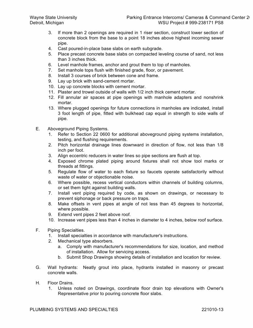
Wayne State University Parking Entrance Intercoms/ Cameras & Command Center 2013 Detroit, Michigan WSU Project # 999-238171 PS8
PLUMBING SYSTEMS AND SPECIALTIES 221010-13
3. If more than 2 openings are required in 1 riser section, construct lower section of concrete block from the base to a point 18 inches above highest incoming sewer pipe.
4. Cast poured-in-place base slabs on earth subgrade. 5. Place precast concrete base slabs on compacted leveling course of sand, not less
than 3 inches thick. 6. Level manhole frames, anchor and grout them to top of manholes. 7. Set manhole tops flush with finished grade, floor, or pavement. 8. Install 3 courses of brick between cone and frame. 9. Lay up brick with sand-cement mortar. 10. Lay up concrete blocks with cement mortar. 11. Plaster and trowel outside of walls with 1/2 inch thick cement mortar. 12. Fill annular air spaces at pipe openings with manhole adapters and nonshrink
mortar. 13. Where plugged openings for future connections in manholes are indicated, install
3 foot length of pipe, fitted with bulkhead cap equal in strength to side walls of pipe.
E. Aboveground Piping Systems. 1. Refer to Section 22 0600 for additional aboveground piping systems installation,
testing, and flushing requirements. 2. Pitch horizontal drainage lines downward in direction of flow, not less than 1/8
inch per foot. 3. Align eccentric reducers in water lines so pipe sections are flush at top. 4. Exposed chrome plated piping around fixtures shall not show tool marks or
threads at fittings. 5. Regulate flow of water to each fixture so faucets operate satisfactorily without
waste of water or objectionable noise. 6. Where possible, recess vertical conductors within channels of building columns,
or set them tight against building walls. 7. Install vent piping required by code, as shown on drawings, or necessary to
prevent siphonage or back pressure on traps. 8. Make offsets in vent pipes at angle of not less than 45 degrees to horizontal,
where possible. 9. Extend vent pipes 2 feet above roof. 10. Increase vent pipes less than 4 inches in diameter to 4 inches, below roof surface.
F. Piping Specialties. 1. Install specialties in accordance with manufacturer's instructions. 2. Mechanical type absorbers.
a. Comply with manufacturer's recommendations for size, location, and method of installation. Allow for servicing access.
b. Submit Shop Drawings showing details of installation and location for review.
G. Wall hydrants: Neatly grout into place, hydrants installed in masonry or precast concrete walls.
H. Floor Drains. 1. Unless noted on Drawings, coordinate floor drain top elevations with Owner's
Representative prior to pouring concrete floor slabs.

Wayne State University Parking Entrance Intercoms/ Cameras & Command Center 2013 Detroit, Michigan WSU Project # 999-238171 PS8
PLUMBING SYSTEMS AND SPECIALTIES 221010-14
2. Set floor drains at proper elevations to attain satisfactory floor drainage. 3. Set tops of floor drain strainers approximately 3/8 inch below level of finished
floor, cast drains into concrete or terrazzo when floors are poured, and make watertight.
4. Maintain drain's position during pour. 5. Locate floor drains where they receive sufficient water to maintain seals in traps. 6. Upon demand of plumbing inspector, install water connection for renewing trap
seals.
I. Roof drains. 1. Install and connect roof drains in strict accordance with requirements of
manufacturer. 2. Coordinate installation with roof installation work to ensure proper drain
elevations. 3. After flashing has been installed, make certain clamping collar is properly installed
and secured.
J. Cleanouts. 1. Install cleanouts where indicated and as required by applicable codes. 2. Aesthetically locate cleanouts with respect to tile patterns, masonry bond, and
alignment. Coordinate installation with concrete and masonry work. 3. Install cleanouts at ends of main and branch runs, at traps, in horizontal drainage
lines changing direction 45 degrees or more, and at or near base of each vertical waste, soil stack, or conductor.
4. Where stack cleanouts are installed within walls, extend cleanout to back of wall and conceal with removable wall cover.
5. In straight trunk line sewers, sized 6 inches and smaller having no change in direction, install cleanouts on 50 foot centers maximum.
6. Install manholes for pipe sized 8 inches and larger at minimum 400 feet intervals and at every change in direction, grade elevation, and size.
7. Take below grade cleanout connections off top of drainage lines at angle of 45 degrees to pipe axis.
8. Install cleanouts in accessible locations and with minimum of 18 inches clearance. 9. Remove each threaded plug from cleanout assembly and make free turning. 10. Prior to acceptance of system, demonstrate that cleanout plugs are easily
removable and that cleanouts can be easily rodded with standard rodding tools, if requested by Owner's Representative.
K. Flashing. 1. Extend flashing minimum of 6 inches beyond outside edge of drainage specialty,
or not less than 24 inches square. 2. Fit flashing into flashing clamp and flange, work outside edge into floor
construction and make watertight. 3. Flashing shall not obstruct weepholes. 4. Flashing not required for floors on grade. 5. Plastic waterproofing membrane may be used instead of sheet lead for flashing
floor drains, hub outlets, or cleanouts. Install in accordance with manufacturer's recommendations.
6. Set roof drain flashing loosely in place, ready for installation under Division 07. 7. Pipe flashing, refer to Section 22 0600 for pipe flashing requirements.

Wayne State University Parking Entrance Intercoms/ Cameras & Command Center 2013 Detroit, Michigan WSU Project # 999-238171 PS8
PLUMBING SYSTEMS AND SPECIALTIES 221010-15
3.2 FIELD QUALITY CONTROL
A. Plumbing Systems Testing. 1. In accordance with applicable general testing requirements specified in Section 22
0600 and as specified in this Section. 2. Test pressure systems at 1-1/2 times systems operating pressure, or at test
pressures indicated below, whichever is greater. 3. Use hydro pressure test at 1-1/2 times system operating pressure or 150 psig
whichever is greater for not less than 2 hours. a. Allowable Pressure loss.
1) Potable Water: Not more than 0 psig.
B. Drainage, Waste, and Vent Piping Testing. 1. Test piping hydrostatically at static head of 10 feet. No leakage is acceptable. 2. Air tests may be substituted for hydrostatic tests by forcing air into closed system
at uniform pressure sufficient to equalize column of mercury 10 inches in height or pressure of 5 psi.
3. Test aboveground piping by closing openings in piping system, except highest opening above roof, and by filling to point of overflowing.
4. Test pressure shall remain constant, after stabilization, for not less than 15 minutes without further addition of water or air.
5. Maintain test pressure in aboveground systems for one hour. 6. Maintain test pressure in underground systems for one hour.
C. Testing of Backflow Prevention Devices. 1. Performed by certified tester. 2. Assure performance within limits of local Department of Public Health cross
connection rules
D. Plumbing Systems Flushing. 1. Flush in accordance with applicable general flushing requirements specified in
Section 22 0600 and as specified in this Section. 2. Flush potable and nonpotable water systems after successful hydrostatic and leak
tests, and cleaning operations. 3. Prior to testing, thoroughly flush piping with water for period of 15 minutes or
longer, to ensure removal of dirt, scale, oil, cuttings, and other foreign matter from piping system.
E. Potable Water Systems Disinfection. 1. Disinfecting of complete water systems shall be in accordance with AWWA C651,
and in accordance with requirements of state or local authorities. 2. Disinfection process shall be done only by company specializing in water
treatment, having experienced operators, and appropriate equipment. 3. Conduct work under supervision of governing local or state authorities. 4. Disinfect completed potable water supply lines and distribution systems, with
chlorine, before being placed in operation. 5. Chlorine dosage: Not be less than 50 parts per million. 6. Flush chlorinated water from system, following contact period, with clear water
until residual chlorine content is not greater than 0.2 part per million.

Wayne State University Parking Entrance Intercoms/ Cameras & Command Center 2013 Detroit, Michigan WSU Project # 999-238171 PS8
PLUMBING SYSTEMS AND SPECIALTIES 221010-16
7. Open and close valves in disinfected water lines at least four times during sterilization period.
END OF SECTION 221010
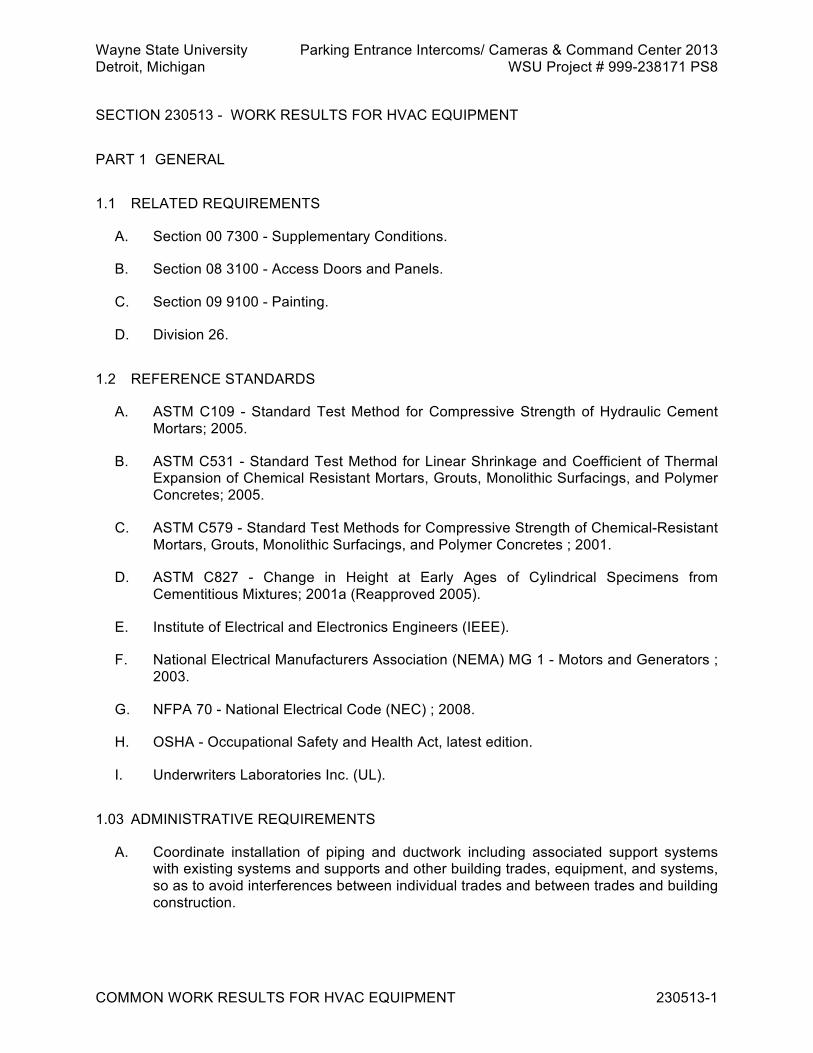
Wayne State University Parking Entrance Intercoms/ Cameras & Command Center 2013 Detroit, Michigan WSU Project # 999-238171 PS8
COMMON WORK RESULTS FOR HVAC EQUIPMENT 230513-1
SECTION 230513 - WORK RESULTS FOR HVAC EQUIPMENT PART 1 GENERAL 1.1 RELATED REQUIREMENTS
A. Section 00 7300 - Supplementary Conditions.
B. Section 08 3100 - Access Doors and Panels.
C. Section 09 9100 - Painting.
D. Division 26. 1.2 REFERENCE STANDARDS
A. ASTM C109 - Standard Test Method for Compressive Strength of Hydraulic Cement Mortars; 2005.
B. ASTM C531 - Standard Test Method for Linear Shrinkage and Coefficient of Thermal Expansion of Chemical Resistant Mortars, Grouts, Monolithic Surfacings, and Polymer Concretes; 2005.
C. ASTM C579 - Standard Test Methods for Compressive Strength of Chemical-Resistant Mortars, Grouts, Monolithic Surfacings, and Polymer Concretes ; 2001.
D. ASTM C827 - Change in Height at Early Ages of Cylindrical Specimens from Cementitious Mixtures; 2001a (Reapproved 2005).
E. Institute of Electrical and Electronics Engineers (IEEE).
F. National Electrical Manufacturers Association (NEMA) MG 1 - Motors and Generators ; 2003.
G. NFPA 70 - National Electrical Code (NEC) ; 2008.
H. OSHA - Occupational Safety and Health Act, latest edition.
I. Underwriters Laboratories Inc. (UL). 1.03 ADMINISTRATIVE REQUIREMENTS
A. Coordinate installation of piping and ductwork including associated support systems with existing systems and supports and other building trades, equipment, and systems, so as to avoid interferences between individual trades and between trades and building construction.

Wayne State University Parking Entrance Intercoms/ Cameras & Command Center 2013 Detroit, Michigan WSU Project # 999-238171 PS8
COMMON WORK RESULTS FOR HVAC EQUIPMENT 230513-2
B. Design of mechanical and electrical systems in ceiling space and truss space has been coordinated to avoid interferences between major components of each system. 1. Final coordination of components shall be performed by installation contractors. 2. Contract documents include suggested ceiling space and truss space zoning
concepts to assist contractors in final coordination.
C. Prepare piping and ductwork installation drawings for purpose of coordination with other trades. Sheet metal contractor shall be responsible for collecting installation documentation from mechanical, electrical, and information technology (IT) trades and create coordination drawings.
D. General Contractor shall distribute final coordination drawings to all contractors. 1. General Contractor shall schedule periodic coordination meetings to resolve
interferences. 2. Upon mutual agreement to overall coordination by contractors involved,
contractors shall revise their installation drawings to reflect agreed upon location of their respective services.
3. Mechanical contractor shall revise coordination drawings after interferences have been resolved.
4. Fabrication and installation of piping and ductwork shall not commence until coordination drawings have been finalized.
E. Piping and ductwork that is not installed according to final coordination drawings shall be corrected at Contractor’s expense.
1.4 SUBMITTALS
A. Refer to Section 01 3000 – Administrative Requirements, for submittal procedures.
B. For Information. 1. Certificates.
a. Motors for motor operated equipment.
C. For Closeout. 1. Project Record Documents.
a. Power and control circuits of assembly, including ladder type elementary schematic diagrams, and interconnection wiring diagrams, having numbered terminal and wire numbers corresponding to designations on terminal strips and control components.
b. Complete electrical sequence of operation corresponding to control diagrams. 2. Operation and Maintenance Data.
a. Equipment operation and maintenance instructions, each set separately bound in hard cover, 3-ring binder containing same type paper sheets for all items, and consisting of following sections. 1) Description of system. 2) Installation and operating instructions. 3) Maintenance requirements for equipment. 4) Controls and adjustments. 5) Parts lists. 6) System electrical wiring diagrams.

Wayne State University Parking Entrance Intercoms/ Cameras & Command Center 2013 Detroit, Michigan WSU Project # 999-238171 PS8
COMMON WORK RESULTS FOR HVAC EQUIPMENT 230513-3
b. Obtain information from manufacturers of major equipment and control systems on firms that are factory authorized for maintenance and repair services.
c. List containing following information. 1) Type of equipment or system. 2) Name, address, and telephone number of authorized service
organization, including phone number designated for receiving service calls during nonbusiness hours.
3) Names of personnel responsible for receiving or responding to requests for service calls.
1.5 QUALITY ASSURANCE
A. Use vendors and equipment manufacturers capable of furnishing local support.
B. Materials and equipment shall be purchased for this project with manufacturer's full warranty, and certified as specified manufacturer's products. Unacceptable are surplus materials from other projects, obsolete or discontinued products, and products rebuilt, remanufactured, or altered in materials, markings, labels, or nameplates.
C. Furnish equipment that is listed and labeled. 1. Listed and Labeled as defined in NEC Article 100. 2. Listing and Labeling Agency Qualifications, a Nationally Recognized Testing
Laboratory (NRTL) as defined in OSHA Regulation 1910.7.
D. While Owner's Field Representative's drawings and Specifications propose to be complete in all respects as to layout, type of equipment, and materials, drawings and Specifications are not intended to serve as detailed system or equipment location drawings.
E. Prepare detailed piping, duct, sleeve, or insert installation drawings, and equipment location drawings.
F. Submit detailed pipe, duct, and equipment supports indicating location of miscellaneous steel and building steel connections.
G. System drawings shall locate each system in relation to other systems, to electrical work, and to building structure.
H. Mark drawings to identify function of each item, location, and proposed system where item is to be installed.
I. Include Contract drawing on which item is shown and page in Specifications where item is described.
J. If code designation letters are used to identify the specific design of submitted equipment and components, and if code designations are not clearly defined in manufacturer's published literature, submit glossary identifying in complete detail the meaning of code designations used.

Wayne State University Parking Entrance Intercoms/ Cameras & Command Center 2013 Detroit, Michigan WSU Project # 999-238171 PS8
COMMON WORK RESULTS FOR HVAC EQUIPMENT 230513-4
K. Factory furnished equipment and controllers shall be designed to prevent power line disturbances, such as spikes, harmonics, and other irregularities in sine wave configuration of fundamental.
L. Furnish filters or other devices that limit back feeding of disturbances into power supply system and limiting harmonics content to not more than 3 percent of fundamental.
M. Voltage spikes shall not exceed 150 percent of peak system voltage.
N. If equipment is found to destabilize building power supply, furnish, install, and interwire, at no change in Contract price, manufacturer accepted devices and circuits to restore power system stability.
1.6 DELIVERY, STORAGE, AND HANDLING
A. Refer to Section 01 6000 – Product Requirements, for transportation, storage, and handling requirements.
B. Deliver. 1. To site in original unopened containers and pallets bearing manufacturer's name
and brand. 2. Affix labels to products, pallets, and containers. 3. Delivered products and containers without complete labels may be rejected.
C. Store. 1. On level, aboveground platforms. 2. Keep containers dry and free from dust and other airborne contaminants. 3. Protect stored absorptive material from moisture damage. 4. Promptly remove adhesives and adhesive tapes from material and equipment
surfaces, where prolonged contact could damage surfaces.
D. Piping Systems. 1. Cover threaded pipe, fitting, and valve ends with thread protectors. 2. Support stored pipe to prevent permanent deformation from ovalizing, crushing, or
sagging. 3. Protect machined surfaces from nicks, dents, scratches, and abrasions, and
protect valve yokes, stems, handwheels, operators, and linkage from undue stresses.
4. Protect piping from dust and moisture.
E. Equipment. 1. Deliver in cartons, crates, or on sleepers. 2. Hoist, transport, rig, and store equipment to prevent damage. 3. Seal openings to prevent entry of dust, dirt, water, and other contaminants. 4. Store boxed equipment on shelves. 5. Crated equipment and equipment mounted on sleepers may be stored on ground,
if no part of equipment comes in contact with ground or with water.
F. Instrumentation.
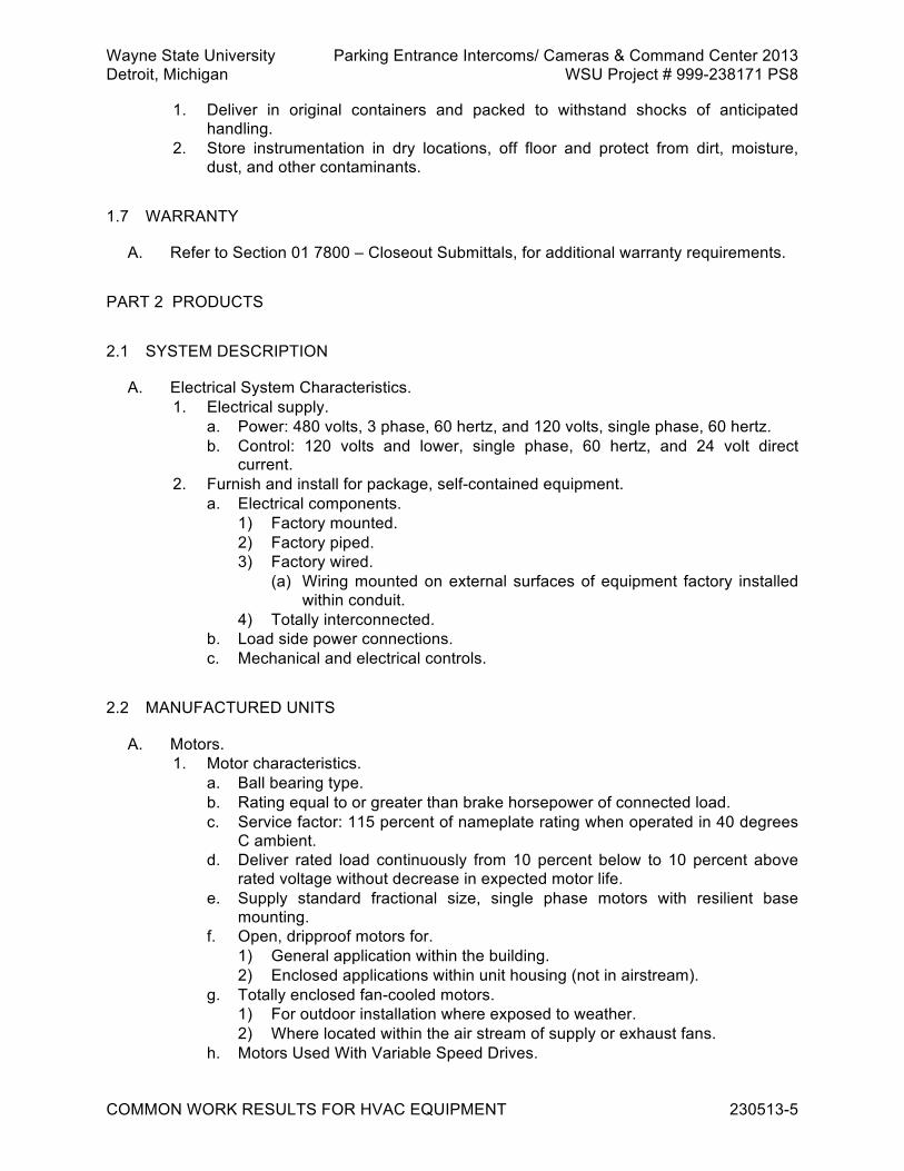
Wayne State University Parking Entrance Intercoms/ Cameras & Command Center 2013 Detroit, Michigan WSU Project # 999-238171 PS8
COMMON WORK RESULTS FOR HVAC EQUIPMENT 230513-5
1. Deliver in original containers and packed to withstand shocks of anticipated handling.
2. Store instrumentation in dry locations, off floor and protect from dirt, moisture, dust, and other contaminants.
1.7 WARRANTY
A. Refer to Section 01 7800 – Closeout Submittals, for additional warranty requirements. PART 2 PRODUCTS 2.1 SYSTEM DESCRIPTION
A. Electrical System Characteristics. 1. Electrical supply.
a. Power: 480 volts, 3 phase, 60 hertz, and 120 volts, single phase, 60 hertz. b. Control: 120 volts and lower, single phase, 60 hertz, and 24 volt direct
current. 2. Furnish and install for package, self-contained equipment.
a. Electrical components. 1) Factory mounted. 2) Factory piped. 3) Factory wired.
(a) Wiring mounted on external surfaces of equipment factory installed within conduit.
4) Totally interconnected. b. Load side power connections. c. Mechanical and electrical controls.
2.2 MANUFACTURED UNITS
A. Motors. 1. Motor characteristics.
a. Ball bearing type. b. Rating equal to or greater than brake horsepower of connected load. c. Service factor: 115 percent of nameplate rating when operated in 40 degrees
C ambient. d. Deliver rated load continuously from 10 percent below to 10 percent above
rated voltage without decrease in expected motor life. e. Supply standard fractional size, single phase motors with resilient base
mounting. f. Open, dripproof motors for.
1) General application within the building. 2) Enclosed applications within unit housing (not in airstream).
g. Totally enclosed fan-cooled motors. 1) For outdoor installation where exposed to weather. 2) Where located within the air stream of supply or exhaust fans.
h. Motors Used With Variable Speed Drives.
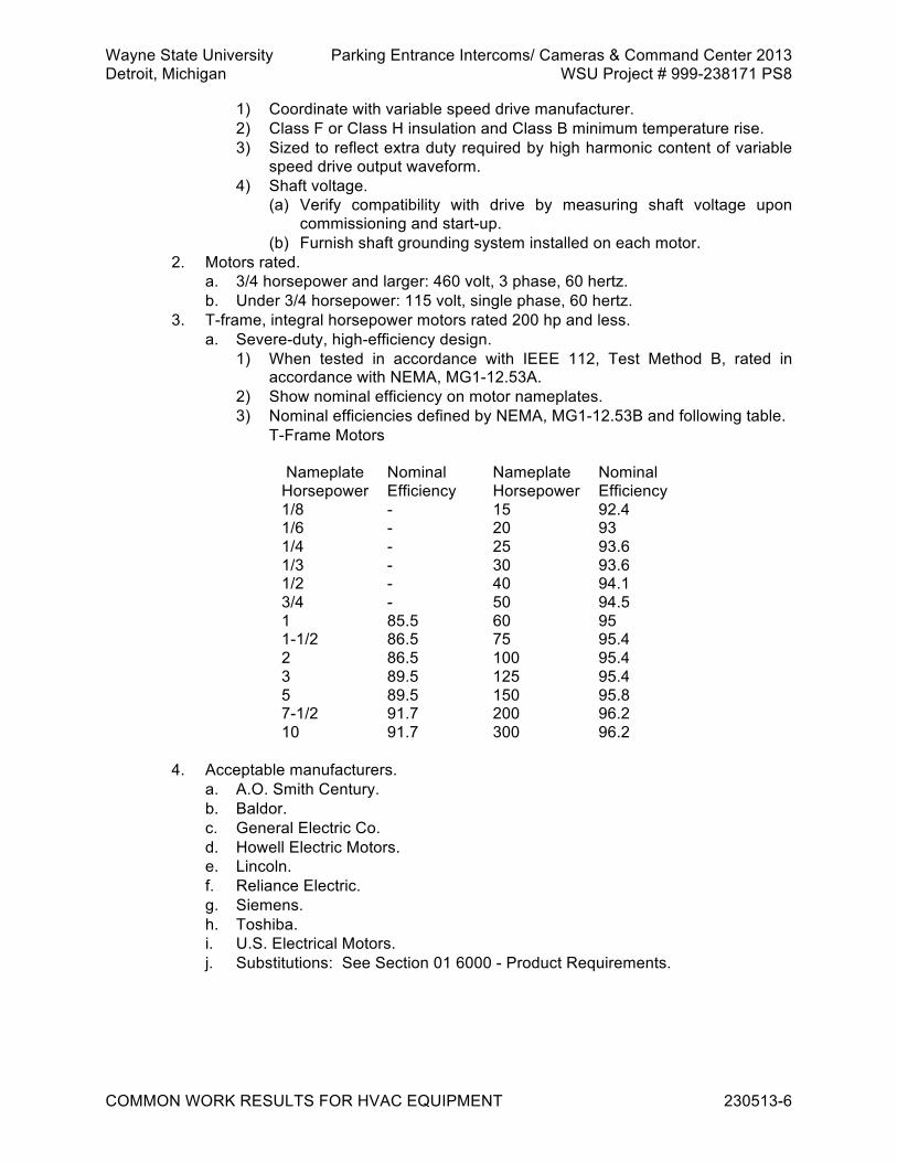
Wayne State University Parking Entrance Intercoms/ Cameras & Command Center 2013 Detroit, Michigan WSU Project # 999-238171 PS8
COMMON WORK RESULTS FOR HVAC EQUIPMENT 230513-6
1) Coordinate with variable speed drive manufacturer. 2) Class F or Class H insulation and Class B minimum temperature rise. 3) Sized to reflect extra duty required by high harmonic content of variable
speed drive output waveform. 4) Shaft voltage.
(a) Verify compatibility with drive by measuring shaft voltage upon commissioning and start-up.
(b) Furnish shaft grounding system installed on each motor. 2. Motors rated.
a. 3/4 horsepower and larger: 460 volt, 3 phase, 60 hertz. b. Under 3/4 horsepower: 115 volt, single phase, 60 hertz.
3. T-frame, integral horsepower motors rated 200 hp and less. a. Severe-duty, high-efficiency design.
1) When tested in accordance with IEEE 112, Test Method B, rated in accordance with NEMA, MG1-12.53A.
2) Show nominal efficiency on motor nameplates. 3) Nominal efficiencies defined by NEMA, MG1-12.53B and following table. T-Frame Motors
Nameplate
Horsepower Nominal Efficiency
Nameplate Horsepower
Nominal Efficiency
1/8 - 15 92.4 1/6 - 20 93 1/4 - 25 93.6 1/3 - 30 93.6 1/2 - 40 94.1 3/4 - 50 94.5 1 85.5 60 95 1-1/2 86.5 75 95.4 2 86.5 100 95.4 3 89.5 125 95.4 5 89.5 150 95.8 7-1/2 91.7 200 96.2 10 91.7 300 96.2
4. Acceptable manufacturers.
a. A.O. Smith Century. b. Baldor. c. General Electric Co. d. Howell Electric Motors. e. Lincoln. f. Reliance Electric. g. Siemens. h. Toshiba. i. U.S. Electrical Motors. j. Substitutions: See Section 01 6000 - Product Requirements.

Wayne State University Parking Entrance Intercoms/ Cameras & Command Center 2013 Detroit, Michigan WSU Project # 999-238171 PS8
COMMON WORK RESULTS FOR HVAC EQUIPMENT 230513-7
2.3 MATERIALS
A. Housekeeping Pads. 1. Furnish and install anchor plates, foundation bolts, nuts, and washers for setting
of equipment. 2. Construct of 2500 psi concrete mixture, shaped to accommodate equipment it
supports, with smooth top surface and 1 inch beveled edges, sized not less than 4 inches above floor level and 2 inches beyond perimeter of supported equipment or equipment bedplate.
3. Furnish anchor plates, bolts, nuts, washers, and bolt inserts required for secure mounting of equipment.
4. Locate anchor bolt inserts in pouring forms prior to pouring concrete foundations and concrete housekeeping pads.
5. Maintain inserts in position and in proper alignment during pouring and setting of concrete.
6. Anchor bolts shall be screwed into inserts prior to concrete pour in order to maintain insert bolt holes free of concrete.
7. Wood, fiber, or lead insert plugs are prohibited.
B. Grouting. 1. Furnish and install grout for setting of equipment bases, rails and bedplates, and
pipe supports located on building floors, concrete slabs, foundations, inertia blocks, and housekeeping pads.
2. Cementitious grout. a. Consist of premixed, prepackaged materials supplied by manufacturer,
requiring only the addition of potable water. b. Performance criteria (high-flow epoxy grout).
1) Zero shrinkage when tested in accordance with ASTM C827. 2) Effective bearing area not less than 95 percent in hardened state, when
measured in accordance with ASTM C827. 3) Compressive strength of not less than 5000 psi at 28 days when tested
in accordance with ASTM C109. 4) Containing no metallic particles, aluminum powder, or expansive cement.
c. Acceptable products. 1) L and M Construction Chemicals, Crystex. 2) Master Builders, Masterflow 928 and 713. 3) U.S. Grout, Five Star Grout. 4) Dayton Superior, Sure-Grip High Performance Grout. 5) Substitutions: See Section 01 6000 - Product Requirements.
3. Epoxy-based grout. a. Pourable, 100 percent solids epoxy system consisting of 3 premeasured,
prepackaged components. b. Performance criteria (regular epoxy grout).
1) Suitable for installation in annular spaces of 2 inches and greater. 2) Zero shrinkage when tested in accordance with ASTM C827. 3) Effective bearing area not less than 95 percent in hardened state, when
measured in accordance with ASTM C827. 4) Compressive strength measured in accordance with ASTM C579,
Method B.
Wayne State University Parking Entrance Intercoms/ Cameras & Command Center 2013 Detroit, Michigan WSU Project # 999-238171 PS8
COMMON WORK RESULTS FOR HVAC EQUIPMENT 230513-8
(a) Not less than 5000 psi at 24 hours. (b) Not less than 10,000 psi at 7 days.
5) Maximum thermal coefficient of expansion, 0.00003 inch per inch per degree F, when tested in accordance with ASTM C531.
c. Acceptable products (regular epoxy grout). 1) Dayton Superior, Sure-Grip Epoxy Grout. 2) L and M Construction Chemicals, Epo Grout. 3) Master Builders Technologies, Brutem 19 Grout. 4) Philadelphia Resins, Chockfast Orange Grout. 5) U.S. Grout, Five Star Epoxy Grout. 6) Substitutions: See Section 01 6000 - Product Requirements.
4. High-flow epoxy grout a. Performance criteria.
1) Suitable for installation in annular spaces of less than 2 inches. 2) Zero shrinkage when tested in accordance with ASTM C827. 3) Effective bearing area not less than 95 percent in hardened state, when
measured in accordance with ASTM C827. 4) Compressive strength measured in accordance with ASTM C579,
Method B. (a) Not less than 5000 psi at 24 hours. (b) Not less than 10,000 psi at 7 days.
5) Maximum thermal coefficient of expansion, 0.00003 inch per inch per degree F, when tested in accordance with ASTM C531.
b. Acceptable products (high flow epoxy grout). 1) Master Builders Technologies, 650 High Flow and Brutem 19-HF. 2) Philadelphia Resins, Chockfast Gray Grout. 3) U.S. Grout, Five Star Speed Epoxy Chock. 4) Substitutions: See Section 01 6000 - Product Requirements.
C. Safety Cables. 1. Furnish 3/16 inch steel rope safety cables for motors on suspended air handling
equipment. 2. Attach cables to motors and to building construction by clamps or other
acceptable means. PART 3 EXECUTION 3.1 INSTALLATION
A. Disposal of Removed Materials and Equipment. 1. Refer to Section 00 7300 - Supplementary Conditions, for removal and disposal of
hazardous materials. 2. Take possession of and remove from Owner's premises, materials and equipment
indicated to be removed and not reinstalled.
B. Equipment Rigging Over Roof Areas. 1. Protect building structure against damage during equipment rigging. 2. Make provisions to distribute load of equipment to main roof structure and crib,
and to prevent damage to metal roof decking, roofing, or purlins.

Wayne State University Parking Entrance Intercoms/ Cameras & Command Center 2013 Detroit, Michigan WSU Project # 999-238171 PS8
COMMON WORK RESULTS FOR HVAC EQUIPMENT 230513-9
C. Painting. 1. Include Section 09 9100 for painting mechanical work. 2. Equipment shall be either factory prime coated or factory finish painted. 3. Perform touch up where factory prime coat or factory finish have been scratched,
abraded, dulled, or otherwise damaged or rendered unsightly. 4. Touch up shall restore original finish as to color, texture, and gloss, and shall be
indistinguishable from original finish.
D. Openings in Building Structure. 1. Openings for air handling system, equipment, components, and ducts.
a. Specified in other Sections. b. Cut required metal deck openings for ductwork.
2. For new piping, tubing, and conduit openings in existing concrete. a. Locate reinforcing bars prior to coring hole by x-ray or other approved means. b. Do not cut reinforcing bars. c. Furnish and install pipe sleeves and caulk sleeves in position. d. Cut piping, tubing, and conduit openings in existing masonry by coring or with
drill points and chisels. 3. For piping, tubing, and conduit openings in new concrete.
a. Furnish and install sleeves in concrete formwork and maintain their position during pouring and setting of concrete.
b. Where concrete floors incorporate permanent metal forms, cut forms and install sleeves to penetrate metal forms.
4. For piping, tubing, and conduit openings in new masonry. a. Furnish sleeves to jobsite, for installation in other Sections. b. Coordinate location of sleeves with masonry work.
E. Cut Openings for Piping and Ducts. 1. In smoke baffles, draft curtains, or vertical metal deck closures neat and straight,
without dents or jagged edges. 2. Opening sizes shall not be larger than piping and ducts passing through them. 3. Reinforce edges of duct openings with angle iron frames. 4. Close unused openings with metal siding or sheet metal, securely fastened to
baffle faces.
F. Work on Existing Ceilings. 1. Remove, protect from damage or soiling, and store components of existing
suspended ceilings that interfere with work in existing ceiling spaces. 2. After completion of work inside of ceiling spaces, restore removed ceilings to
original condition. 3. Furnish and install new ceilings and suspension systems, where existing ceilings
are damaged or marred. 4. Perform work to minimize damage and to leave ceilings in best possible condition. 5. Work shall be done by experienced personnel regularly employed as installers by
manufacturers of suspended ceiling systems.
G. Access Doors in Walls and Ceilings. 1. Coordinate installation of access doors with other trades where required to
maintain serviceability of mechanical system components. 2. Refer to Section 08 3100, Access Doors and Frames.

Wayne State University Parking Entrance Intercoms/ Cameras & Command Center 2013 Detroit, Michigan WSU Project # 999-238171 PS8
COMMON WORK RESULTS FOR HVAC EQUIPMENT 230513-10
H. Systems and Equipment. 1. Where Contract requires work to exceed standards required by applicable laws,
ordinances, rules, regulations, or other statutory provisions, perform and complete work in accordance with Contract requirements.
2. Install systems and equipment in accordance with Shop Drawings reviewed by Owner's Field Representative.
3. Coordinate installation of piping, ductwork, and mechanical equipment with work of other Sections to avoid interferences.
4. To minimize interference with Owner's operations, consult with Owner's Representative as to methods of carrying on work.
5. Resolve interferences with other work. 6. Avoid system intrusion into occupied space, unsightliness, and clutter. 7. Maintain clearances for installation, operation, expected motion, actuation,
servicing, removal, and reinstallation of system components and equipment. 8. Arrange piping systems for uniform specified pitch, for complete drainability, and
for ready ventability.
I. Grouting of Equipment Bases, Rails and Bedplates, and Pipe Supports. 1. Perform grouting in accordance with requirements of grout manufacturer. 2. Cure concrete surfaces for minimum of 14 days prior to placing grout. 3. Clean and roughen surfaces to ensure bond of grout to concrete. 4. Clean anchor sleeves of debris and moisture. 5. Furnish and install forms, including chamfer edge strips around perimeter of
equipment prior to placing grout. 6. After equipment has been set in place, leveled, shimmed, and anchored, grout
anchor bolt sleeves and allow to set 24 hours before completing grouting of equipment base.
7. Apply grouting to base to ensure support for entire contact area of base. 8. Work grout with push rods or link chains until air pockets are eliminated. 9. After grout has acquired initial set, remove shim plates and jacking bolts and fill
voids with grout. 10. After grout has cured, remove forms and trim grout to ensure smooth finish. 11. Tighten anchor bolts prior to start of equipment and retighten following initial
equipment operation. 3.2 FIELD QUALITY CONTROL
A. General. 1. Upon completion of work, prior to testing, conduct final inspection and ensure
fixtures, equipment, and piping have been cleaned and placed in complete and satisfactory working order.
B. Equipment. 1. Furnish manufacturer's factory authorized service for adjustments and start-up,
where required for preservation of guarantees. 2. Do not jog or start equipment until completion of factory authorized service. 3. Clean and degrease equipment. 4. Check nameplates for readability.
a. Remove paint smears.

Wayne State University Parking Entrance Intercoms/ Cameras & Command Center 2013 Detroit, Michigan WSU Project # 999-238171 PS8
COMMON WORK RESULTS FOR HVAC EQUIPMENT 230513-11
b. Where nameplates are illegible, arrange for replacement by equipment manufacturer.
5. Motor driven equipment. a. Start equipment and make sure thermal overload protection will not shut
down motor during acceleration period. b. Check motors for direction of rotation. c. Obtain assistance where required to reverse motor rotation. d. Check identification, instruction, and warning labels. e. Prepare lubrication schedule and deliver this schedule to Owner. f. Schedule for each piece of equipment to include.
1) Locations for lubricant application. 2) Type of lubricant. 3) Lubricating device. 4) Quantity of lubricant to be dispensed during each application. 5) Frequency of lubrication.
g. Check for factory applied lubrication and add lubricant where required. h. In particular, make sure extended lubricating lines are completely filled. i. Check bearing seals.
1) Replace blown seals with seals complying with Contract criteria. 2) Check associated bearings for foreign matter and damage. 3) Flush and relubricate, or furnish and install seals complying with Contract
criteria. j. Turn equipment shafts by hand to check for binding or rough bearing action.
1) Investigate causes of binding and rough bearing action. 2) Repair, adjust, or furnish and install components complying with Contract
criteria to achieve proper operation. 3) In particular, furnish and install roller and ball bearings complying with
Contract criteria if bearings exhibit evidence of race pitting, brinelling, rust, or discoloration.
k. Check rotating equipment for smooth operation. l. Rebalance or replace rough running equipment. m. Confirm shaft voltages are 3 volts or less to ground for all motors used with
variable speed drives. 6. Flush out corrosion inhibiting compounds, where applied by manufacturer to
prevent deterioration in transit and storage. 7. Witness and certify Acceptance Document for each piece of equipment and each
system. END OF SECTION 230513

Wayne State University Parking Entrance Intercoms/ Cameras & Command Center 2013 Detroit, Michigan WSU Project # 999-238171 PS8
VIBRATION AND SEISMIC CONTROLS FOR HVAC EQUIPMENT 230548-1
SECTION 230548 - VIBRATION AND SEISMIC CONTROLS FOR HVAC EQUIPMENT PART 1 GENERAL 1.1 RELATED REQUIREMENTS
A. Section 23 0600 - Basic HVAC Materials and Methods.
B. Section 23 3100 - HVAC Ducts and Casings.
C. Section 23 7400 - Packaged HVAC Equipment. 1.2 REFERENCE STANDARDS
A. ASHRAE (HVACA) - ASHRAE Handbook - HVAC Applications ; 2007. 1.3 SUBMITTALS
A. Refer to Section 01 3000 – Administrative Requirements, for submittal procedures.
B. For Review.
C. For Information. 1. Product data.
a. Vibration isolators indicating. 1) Equipment requiring isolation. 2) Spring outside diameters. 3) Free, operating, and solid heights.
2. Design data. a. Weight of equipment. b. Distribution of weight to support points. c. Report of air mount pressure test.
PART 2 PRODUCTS 2.1 MANUFACTURED UNITS
A. Selection Criteria. 1. Select vibration isolators for actual load imposed, and in accordance with Table,
Selection Guide for Vibration Isolation, in the Sound and Vibration Control chapter of the ASHRAE HVAC Applications.
2. Scheduled or specified static deflection requirements relate to actual static deflection of individual mounts under their particular loads.
3. Unacceptable vibration isolator mounts include.
Wayne State University Parking Entrance Intercoms/ Cameras & Command Center 2013 Detroit, Michigan WSU Project # 999-238171 PS8
VIBRATION AND SEISMIC CONTROLS FOR HVAC EQUIPMENT 230548-2
a. Vibration isolator mounts selected on the basis of cataloged, nominal static, deflection, while ignoring decrease in isolation efficiency due to loadings to less than those of nominal rating.
b. Isolator mounts loaded in excess of their rated load capacity. c. Isolators selected by equally dividing total weight of equipment by proposed
number of isolators. 1) Except where supported equipment is symmetrical about its vertical axis.
4. Isolator springs shall have ratio of horizontal to vertical spring constants of not less than 0.8, be horizontally unrestrained, of diameter not less than 80 percent of height at rated load and allow reserve travel of 50 percent of rated deflection from height at rated load to shorted turns condition.
5. Elastic limit of springs shall not be exceeded at shorted turns conditions. 6. Equip isolator mounts having steel springs with means for leveling suspended
equipment. 7. Floor mounts.
a. Equip with leveling bolts and locknuts. b. Select for convenient bolting of base plates to building structure.
8. Hanger mounts. a. Furnish positioning type hanger isolators that allow installation of equipment
and piping at fixed elevation independent of load changes and subsequent transfer of suspension load to springs.
b. Option, preloaded hanger isolators may be furnished with preloading devices being backed off after installation.
B. Dip coat steel elements of outdoor isolators with weather resistant paint.
C. Vibration Isolator Mountings. 1. Type D, Spring Floor Mount.
a. Individual steel spring mounts supported on elastomer pads. b. Acceptable products.
1) Korfund Dynamics, Type WS Bolt Down Design. 2) Mason Industries, Type SLFH. 3) Kinetics, Model FDS Bolt Down Mounts. 4) Vibration Eliminator, Type OST. 5) Vibration Mountings and Controls, Type AWH.
2. Type H, Combination Spring and Neoprene-in-Shear Hanger Mount. a. Hanger isolators with steel springs mounted in series with elastomer
elements. b. Acceptable products.
1) Korfund Dynamics, Type VSPL. 2) Mason Industries, Type PC30N. 3) Kinetics, Model SRHPL. 4) Vibration Eliminator, Type PCSR. 5) Vibration Mountings and Controls, Series RSHP.
3. Type J, Neoprene-in-Shear Hanger Mount. a. Hanger isolators with elastomer elements. b. Acceptable products.
1) Korfund Dynamics, Type H. 2) Mason Industries, Type HD.

Wayne State University Parking Entrance Intercoms/ Cameras & Command Center 2013 Detroit, Michigan WSU Project # 999-238171 PS8
VIBRATION AND SEISMIC CONTROLS FOR HVAC EQUIPMENT 230548-3
3) Kinetics, Model RH. 4) Vibration Eliminator, C Series. 5) Vibration Mountings and Controls, Series RHDC.
4. Type K, Thrust Restraint. a. Thrust restraint, having spring with elastomer element mounted in series,
housing, rods, brackets, and means for presetting thrust force. b. Acceptable products.
1) Korfund Dynamics, Thrust Restraints. 2) Mason Industries, Type WB. 3) Kinetics, Thrust Restrainer. 4) Vibration Eliminator, Thrust Restraints. 5) Vibration Mountings and Controls, SH-27.
PART 3 EXECUTION 3.1 INSTALLATION
A. General. 1. Install vibration isolation materials and equipment bases in accordance with
manufacturer's written instructions. 2. Level mountings so each mount carries assigned load.
a. Mounts showing evidence of insufficient or excessive loading, buckling, squirming, totally collapsed springs, making permanent contact with lift or sag restraints, or shorted springs and elastomer elements will not be accepted.
3. Install hanger type isolators so shorting will not occur via contact between upper and lower hanger rods or via contact between lower hanger rods and isolator boxes.
4. Locate floor vibration isolator mounts so base plates are supported in horizontal position by floor slabs, beams, or other structural elements.
5. Isolator placements resulting in overhanging or tilted base plates or in bending stresses in steel plate or bar grate flooring are unacceptable.
6. Bolt base plates to supporting structure. 7. Level vibration isolator mounts and bases, to attain fully floating equipment
suspension under loading conditions of actual operation and adjust restraints. 8. Adjust or replace defective elements as required. 9. After installation of isolation materials and before start up of equipment, clear
debris from areas surrounding and beneath isolated equipment. 10. No rigid connections between equipment and building structure shall be made that
degrades noise and vibration isolation system. 11. Electrical conduit connections to isolated equipment shall be installed with slack to
allow free motion of isolated equipment.
B. Application of Mounting Types. 1. Mountings: Types scheduled on drawings. 2. Static deflection requirements: Where not indicated, defined in ASHRAE
Handbook - HVAC Applications. 3. Ductwork located within 50 feet of connections to air handling units: Support with
Type H vibration isolators selected for a static deflection of 0.75 inch.

Wayne State University Parking Entrance Intercoms/ Cameras & Command Center 2013 Detroit, Michigan WSU Project # 999-238171 PS8
VIBRATION AND SEISMIC CONTROLS FOR HVAC EQUIPMENT 230548-4
4. Fans and air handling units: At flexible connections install Type K thrust restraints, where developed aerodynamic thrust exceeds 10 percent of weight, and where fan static pressure exceeds 5 inches water gauge.
5. Piping to vibration isolated equipment located within 3 hanger spacings of connection: Support with Type H vibration isolators selected for a static deflection of not less than 1 inch.
END OF SECTION 230548

Wayne State University Parking Entrance Intercoms/ Cameras & Command Center 2013 Detroit, Michigan WSU Project # 999-238171 PS8
IDENTIFICATION FOR HVAC PIPING AND EQUIPMEN 230553-1
SECTION 230553 - IDENTIFICATION FOR HVAC PIPING AND EQUIPMENT PART 1 GENERAL 1.1 REFERENCE STANDARDS
A. ANSI A13.1 - Scheme for the Identification of Piping Systems ; 1981 (R1993). 1.2 SUBMITTALS
A. Refer to Section 01 3000 – Administrative Requirements, for submittal procedures.
B. For information. 1. Product data.
a. Pipe markers. b. Equipment identification labels.
1.03 DELIVERY, STORAGE, AND HANDLING
A. Refer to Section 01 6000 – Product Requirements, for transportation, storage, and handling requirements.
PART 2 PRODUCTS 2.1 SYSTEM DESCRIPTION
A. Pipe Markers. 1. Furnish and apply custom-made pipe markers to piping defined as follows.
a. Piping exposed to view. 1) Piping exposed to view includes piping located in equipment rooms or in
spaces that do not conceal the piping. 2) For piping, ductwork and diffusers exposed in the Ballroom, Atrium and
Prefunction Ceiling refer to architectural Room Finish Schedules for specific direction on painting and labeling
b. Piping located above suspended ceilings. c. Piping located in accessible shafts.
2. Pipe markers shall identify fluid handled by each system. 3. Markers for insulated pipe and for bare pipe sized 3/4 inch and larger shall
indicate direction of fluid flow. 2.2 MANUFACTURED UNITS
A. Mechanical Identification (Piping and Ductwork). 1. Markers for pipe sized 3/4 inch and larger.
a. Unless otherwise specified, comply with requirements of ANSI A13.1.

Wayne State University Parking Entrance Intercoms/ Cameras & Command Center 2013 Detroit, Michigan WSU Project # 999-238171 PS8
IDENTIFICATION FOR HVAC PIPING AND EQUIPMEN 230553-2
b. Background of markers shall be color coded. c. Legends shall be in long form or they may be abbreviated only if they are in
common, everyday usage and not prone to misinterpretation. d. Directional arrows shall point away from legend. e. Pipe markers shall be plastic and coated to resist smudging and damage
from water and weather. f. Pipe markers shall be snap-on or strap-on type. g. Acceptable products.
1) W.H. Brady, Quick-Labels. 2) Craftmark Identification Systems, Specmark. 3) Emed. 4) Marking Services, Inc. 5) Seton, Setmark. 6) Substitutions: See Section 01 6000 - Product Requirements
2. Markers for bare pipe smaller than 3/4 inch nominal size. a. Circular brass tags identifying service and suspended by means of brass jack
chains. 1) Legends shall be largest type which can be accommodated.
b. Snap-on labels specifically made for small diameter pipe and tubing. c. Acceptable products.
1) W.H. Brady, Style No. 28. 2) Craftmark Identification Systems. 3) Emed. 4) Marking Services, Inc. 5) Seton, Valve Tags. 6) Substitutions: See Section 01 6000 - Product Requirements
B. Ceiling Identification Markers. 1. Celluloid covered, 5/8 inch diameter marking tacks suitable for ink notation on
colored face. 2. Color code indicating.
a. Yellow for HVAC valves and cocks. b. Aluminum for orifices and air modulating devices in ductwork. c. Red for fire dampers, smoke dampers, combination fire/smoke dampers, and
fire protection valves. d. Green for plumbing valves.
3. Acceptable manufacturers. a. Moore. b. Seton. c. Substitutions: See Section 01 6000 - Product Requirements
C. Valve Tags. 1. Circular brass tags identifying service and suspended by means of brass jack
chains. a. Legends shall be largest type which can be accommodated. b. Acceptable products.
1) W.H. Brady, Style No. 28. 2) Craftmark Identification Systems. 3) Emed.

Wayne State University Parking Entrance Intercoms/ Cameras & Command Center 2013 Detroit, Michigan WSU Project # 999-238171 PS8
IDENTIFICATION FOR HVAC PIPING AND EQUIPMEN 230553-3
4) Marking Services, Inc. 5) Seton, Valve Tags. 6) Substitutions: See Section 01 6000 - Product Requirements
D. Equipment Identification and Duplicate Motor Nameplate Data. 1. Laminated white plastic nameplates with black engraved letters. 2. Acceptable products.
a. W.H. Brady. b. Craftmark Identification Systems. c. Emed. d. Marking Services, Inc. e. Seton. f. Substitutions: See Section 01 6000 - Product Requirements
PART 3 EXECUTION 3.1 INSTALLATION
A. Mechanical Identification (Piping and Ductwork). 1. Apply pipe markers for piping specified to be painted, after painting has been
completed. 2. Prior to application of snap-on labels, or brass tags, remove debris and dust from
contact surfaces. 3. Unless otherwise specified, locate pipe markers in accordance with Article 3.1 of
ANSI A13.1, except with 50 foot maximum intervals. 4. Furnish and install markers on piping at connections to equipment. 5. Apply pipe markers for piping specified to be painted, after painting has been
completed. 6. Prior to application of pipe markers, snap-on labels or brass tags, remove dust
and debris from pipe surface. 7. Install pipe markers as follows.
a. At access panels or doors. b. Adjacent to valves and branch connections. c. On both sides of floors, ceilings, and walkways. d. At major changes in direction. e. At maximum intervals of 25 feet on straight lengths of pipe . f. At termination points. g. At connections to equipment.
8. Arrow and marker placement shall furnish unobstructed visibility from floor level. 9. Label ductwork to indicate service, associated fan number, and direction of
airflow. 10. Label ductwork after completion of associated insulation and painting.
B. Ceiling Identification Markers. 1. Install marking tacks in ceiling at points over which mechanical items requiring
service or adjustments are located. 2. Familiarize Owner's maintenance personnel with location and function of markers.
C. Mechanical Equipment.
Wayne State University Parking Entrance Intercoms/ Cameras & Command Center 2013 Detroit, Michigan WSU Project # 999-238171 PS8
IDENTIFICATION FOR HVAC PIPING AND EQUIPMEN 230553-4
1. Label in accordance with Owner's requirements. 2. When electric motor location renders nameplate data inaccessible, install
duplicate motor nameplate data in easily accessible location on equipment. 3.2 FIELD QUALITY CONTROL
A. Check factory installed nameplates for readability. 1. Remove paint smears. 2. Where nameplates are illegible, arrange for replacement by equipment
manufacturer.
B. Check directional arrows and apply corrected labels and arrows, where errors are found.
END OF SECTION 230553
Wayne State University Parking Entrance Intercoms/ Cameras & Command Center 2013 Detroit, Michigan WSU Project # 999-238171 PS8
TESTING, ADJUSTING, AND BALANCING FOR HVAC 230593-1
SECTION 230593 - TESTING, ADJUSTING, AND BALANCING FOR HVAC PART 1 GENERAL 1.01 RELATED REQUIREMENTS
A. Section 23 0513 - Common Work Results for HVAC Equipment.
B. Section 23 0900 - Instrumentation and Control for HVAC.
C. Section 23 2100 - Hydronic Piping and Specialties.
D. Section 23 2123 - Hydronic Pumps.
E. Section 23 3400 - HVAC Fans.
F. Section 23 3600 - Air Terminal Units.
G. Section 23 5701 - Heat Transfer Equipment.
H. Section 23 6000 - Air Conditioning Equipment.
I. Section 23 7400 - Packaged HVAC Equipment. 1.02 REFERENCE STANDARDS
A. AABC MN-1 - AABC National Standards for Total System Balance ; 2002.
B. ACGIH (IV) - Industrial Ventilation, A Manual of Recommended Practice ; 2007, 26th edition.
C. ASHRAE (HVACA) - ASHRAE Handbook - HVAC Applications ; 2007.
D. ASHRAE Guideline 1 - The HVAC Commissioning Process ; 1996.
E. ASHRAE Std 111 - Practices for Measurement, Testing, Adjusting and Balancing of Building Heating, Ventilation, Air-Conditioning, and Refrigeration Systems ; 1988 with 1997 Errata.
F. NEBB (TAB) - Procedural Standards for Testing Adjusting Balancing of Environmental Systems ; 2005, Seventh Edition.
G. SMACNA (TAB) - HVAC Systems Testing, Adjusting, and Balancing ; 2002. 1.03 SYSTEMS DESCRIPTION
A. Test, Adjust, Balance, and Perform Commissioning Work. 1. Air distribution systems, including.

Wayne State University Parking Entrance Intercoms/ Cameras & Command Center 2013 Detroit, Michigan WSU Project # 999-238171 PS8
TESTING, ADJUSTING, AND BALANCING FOR HVAC 230593-2
a. Air handling units. b. Fans. c. Ductwork. d. Air terminal units. e. Kitchen exhaust hoods. f. Door heaters.
2. Hydronic systems, including. a. Heating coils. b. Cooling coils. c. Cabinet Unit Heats. d. Fin tube radiation. e. Pumps. f. Heat exchangers. g. Boilers. h. Hot water converters.
B. Drawings indicate equipment locations, layouts, and general design of systems to be adjusted and balanced. Where only equipment is listed, test, adjust, and balance associated systems.
C. Air distribution systems shall be tested, balanced, and adjusted to meet following criteria. 1. Plus or minus 5 percent of design flow rates for air handling equipment and
outlets. 2. Where terminal units serve 6 or more outlets within a common room, individual
outlets may vary up to plus or minus 10 percent of design flow rates if overall room supply is within plus or minus 5 percent.
D. Hydronic systems shall be tested, balanced, and adjusted to meet following criteria. 1. Plus or minus 5 percent of design flow quantities for hydronic systems. 2. Plus or minus 5 percent of terminal heat transfer for balance by temperature
differentials.
E. Systems shall be started and tested for functional performance in all modes of operation including, Summer/Winter, occupied/unoccupied, warm up/cool down, day/night, full load/part load, recording concurrent performance and weather data in each mode.
F. Systems and equipment shall be commissioned for operation in accordance with design intent, documented for performance, and certified before signing over to Owner.
1.04 SUBMITTALS
A. Refer to Section 01 3000 – Administrative Requirements, for submittal procedures.
B. For Information. 1. Test Reports.
a. Completed test data forms. b. Completed test and balance report forms. c. Complete commission and acceptance documentation forms.

Wayne State University Parking Entrance Intercoms/ Cameras & Command Center 2013 Detroit, Michigan WSU Project # 999-238171 PS8
TESTING, ADJUSTING, AND BALANCING FOR HVAC 230593-3
1.05 QUALITY ASSURANCE
A. Furnish services of independent test and balance agency which meets one of 2 sets of qualifications specified below, and is accepted by Owner and Owner's Field Representative.
B. Assign to this agency responsibility for balancing, adjusting, and testing of systems necessary for attaining flow rates, pressures, pressure differentials, and pressure relationships indicated.
C. Furnish and install additional items required for testing, adjusting, and balancing as recommended by the agency.
D. Agency shall perform Work in accordance with requirements specified in this Section.
E. Qualification Set No. 1. 1. Agency shall be known to offer services limited to balancing, adjusting, and
testing of air systems. 2. Agency shall assign engineer or manager as job supervisor with full job
responsibilities. 3. Agency shall be certified member in good standing of AABC or NEBB, and be
certified for systems test and balance Work specified.
F. Qualification Set No. 2. 1. Agency shall be fabricator and installer of mechanical systems similar to
mechanical systems that shall be tested, but shall not be a party to Contract for manufacture, fabrication, installation, processing, sale or lease of materials, supplies, accessories, equipment, or devices associated with Work of this Project.
2. Agency shall be certified member in good standing of NEBB, and be certified for systems test and balance Work specified.
G. Test Reports. 1. Test data forms shall be forms prepared by agency listed under heading,
References, and shall be submitted completely filled out. 2. If computers are used for calculations and data printouts, standard computer test
data forms may be used, if all required information is included. 3. These forms and explanation of computer program shall be submitted for
acceptance prior to use. 4. Prior to final acceptance, submit 6 copies of test and balance report forms for
review by Owner's Field Representative. 5. Reports shall be neatly typed or printed. 6. Final test reports, accepted and signed, shall be submitted for each system,
including as a minimum. a. Table of contents. b. Summary report. c. Identify each system for type and location. d. Identify and list type, size, location, flow factor, and manufacturer of inlets,
outlets, flow measuring devices, and equipment, as well as associated design
Wayne State University Parking Entrance Intercoms/ Cameras & Command Center 2013 Detroit, Michigan WSU Project # 999-238171 PS8
TESTING, ADJUSTING, AND BALANCING FOR HVAC 230593-4
and actual flow rates, both at maximum, minimum, and partial airflow rates where applicable.
e. Performance data sheets shall be furnished for equipment, including curves and operating information.
f. Obtain data prior to start of Work and mark operating setpoints for record. g. Design and actual temperatures, pressures or differential pressures for each
piece of equipment and for each section of system. h. Applicable test data forms completely filled out. i. Operating conditions of systems. j. Atmospheric conditions or conditions of building or associated systems that
have had effect on results of Work. k. Modes of operation, if more than one. l. Measurements and checks used to ensure accuracy of data obtained and
that tolerances were met. m. Methods or formulas and references used for correcting measured readings. n. Information useful in analysis of test results. o. Certified documentation of instrument calibrations.
H. Definitions. 1. Testing, to determine quantitative performance of equipment. 2. Balancing, to establish specific volumes of flow within distribution system. 3. Adjusting, to regulate specified flow rates and air patterns.
I. Identification Tags. 1. Brass tags, not less than 1 inch diameter, or 1 inch by 2 inch rectangular, secured
with ring and No. 16 brass jack chain. 1.06 ADJUSTING
A. General Testing, Adjusting, and Balancing Requirements. 1. Perform testing and balancing methods and procedures in accordance with one or
more standards specified under heading, References, and in presence of Owner's Representative.
2. Additionally, perform testing and balancing recommended by product manufacturers.
3. Unless otherwise specified, furnish labor, materials, test instruments, ladders, scaffolding, extension cords, tools, and equipment necessary for complete testing, balancing, and adjusting of systems or equipment in the Contract Documents.
4. Prepare and submit test and balance report. 5. Wherever possible, cross-check readings with additional readings to ascertain
that required flow rate is attained. 6. Prior to start of Work, review drawings and Specifications, and if systems may
present difficulties in achieving required balanced flow conditions, notify Owner's Field Representative.
7. If, during course of Work, criteria cannot be met, immediately advise Owner's Field Representative prior to proceeding with Work.
8. Use of orifice plate to balance airflow in air distribution systems instead of air balancing dampers is prohibited.

Wayne State University Parking Entrance Intercoms/ Cameras & Command Center 2013 Detroit, Michigan WSU Project # 999-238171 PS8
TESTING, ADJUSTING, AND BALANCING FOR HVAC 230593-5
9. This does not preclude the use of perforated plates to attain uniform air distribution.
10. Use of orifice plates to balance flow capacities in liquid systems is prohibited, unless indicated on the drawings.
11. Instruments used shall have unexpired calibration dates. 12. Calibration date and date of expiration shall be noted on tag affixed to each
instrument. 13. Submit letter of certification of instrument calibrations as part of final report. 14. Furnish sufficient number of each type of instrument, in order to avoid delays. 15. Recalibrate instruments that are dropped or subjected to severe jarring. 16. In systems with redundant equipment, independently test and adjust each piece of
equipment to operate within design criteria. 17. Owner's Field Representative will determine primary mode of operation in
systems with 2 or more operating modes. 18. After final adjustment in primary mode, secondary modes shall be tested and
system data recorded. 19. Owner's Field Representative will determine whether additional balancing and
adjusting is necessary to meet secondary mode requirements. 20. Coordinate systems test and balance Work with the systems installation. 21. After final adjustment, permanently mark position of balancing devices equipped
with external means of setting the position.
B. Requirements for Testing and Balancing Air Distribution Systems. 1. Test, balance, and adjust air distribution systems, equipment, components, and
system related items to accomplish design objectives. 2. Note air mixing dampers regarding operation, location, and damper blade
orientation for compliance with information on drawings. a. Check air flow within intake plenums and mixing boxes of air handling units
for uneven flow and temperature stratification and prepare a report with profile elevations (temperature and velocity) on each coil or filter face for Owner's Field Representative.
b. In some cases, direction of nonducted air movement from rooms under positive or negative pressure is more relevant than exact airflow rates.
c. These cases will be determined by Owner's Field Representative. d. Direction of nonducted air flows, including air distribution pattern over the
entire door opening, shall be verified by use of smoke tubes with results recorded on data sheets.
e. Coordinate installation and replacement of dampers or devices required for balancing.
f. Mark final fix setting of volume dampers by drilling and pinning the handles with sheet metal screws.
3. Perform testing and adjusting of terminal units and devices in accordance with manufacturer's instructions or in accordance with procedures established by one or more of system's test and balance standards at maximum, minimum, and intermediate load conditions.
4. Mark terminal units calibration curve to indicate minimum and maximum setpoints. 5. Attach identification tags to terminal units identifying box size, room served, and
date of test. 6. Air distribution systems shall be tested, balanced, and adjusted under following
operating conditions.

Wayne State University Parking Entrance Intercoms/ Cameras & Command Center 2013 Detroit, Michigan WSU Project # 999-238171 PS8
TESTING, ADJUSTING, AND BALANCING FOR HVAC 230593-6
a. Tests shall be conducted with supply, return, and exhaust systems operating. b. Doors, windows, hatches, and similar openings shall be closed or in position
to reflect projected operating conditions. c. Systems that may affect system being tested shall be operating at near
design flow and temperatures. d. Whenever possible, final readings and settings shall be made with coils
operating (wet). e. Systems shall operate at design airflow rates with simulated air resistance for
75 percent of dirty filter condition. f. Furnish blankoff panels over filters as required to achieve simulation.
7. Comply with equipment manufacturer's published recommendations and procedures in testing, balancing, and adjusting of device or system.
8. Obtain manufacturer's data on installed air handling equipment. 9. Nameplate data only shall be recorded for nonducted fans with design capacity of
less than 1000 cfm. 10. Adjust total system airflow rates by changing fan speed, inlet vane position, or fan
blade position. a. Use fan speed as primary adjustment to ensure maximum system efficiency. b. Where it is impossible to adjust total system air quantities by methods
outlined above, total may be reduced by use of volume dampers if noise level does not increase beyond acceptable limits, in opinion of Owner's Field Representative.
c. Select required sheave sizes and advise installing contractor to change drive sheaves accordingly.
d. Retest system after fan speed changes or adjustments have been made. 11. Systems with economizer cycles shall be adjusted with winter as primary mode,
and with economizer at 100 percent outside air as secondary operating mode. 12. Systems with different outside air capacities for winter and summer operating
modes shall be adjusted with winter as primary operating mode, and summer as secondary operating mode.
13. Balance branch duct airflow rates with volume dampers. 14. Use dampers that are integral with terminal devices for minute final adjustments
only. 15. Outside air, return air, and exhaust dampers shall be adjusted by using direct flow
readings. 16. Where direct flow readings are impossible or of questionable accuracy, use mixed
air temperature method. 17. Measured readings shall be corrected in following cases.
a. For air temperatures exceeding 120 degrees F or less than 20 degrees F, measured readings shall be corrected to flow rate at 70 degrees F.
b. For installations located at elevations of 2000 feet above sea level or more, measured flow readings shall be corrected for actual flow rate.
C. Air Distribution Systems Measurements. 1. Measurement and adjustment of airflow rates, temperatures, and pressures for
duct systems and components shall be performed in accordance with the following requirements. a. Air flow in main ducts, branch ducts carrying 10 percent or more of total
system capacity, or individual outlets where manufacturer's outlet factor is

Wayne State University Parking Entrance Intercoms/ Cameras & Command Center 2013 Detroit, Michigan WSU Project # 999-238171 PS8
TESTING, ADJUSTING, AND BALANCING FOR HVAC 230593-7
unknown, shall be measured by pitot tube, micromanometer, or hot wire anemometer traverses of duct.
b. For velocities below 500 fpm, use micromanometer with minimum resolution 0.001 inch water gauge.
c. Drill test holes in ducts and seal them with removable, leaktight plugs, suitable for 30 inch water gauge positive or negative pressure.
d. Pitot traverses shall be made with pitot tube and inclined manometer or calibrated differential pressure gauge.
e. Make traverses in duct sections having minimum of 4 diameters in length from nearest transition or obstruction.
f. For pitot traverses in square or rectangular ducts, mark off duct cross section in square areas of equal proportions and insert pitot tube in center of each square.
g. Number of squares need not be more than 64. h. For less than 64, use maximum of 6 inch square. i. Record gauge readings for each area and average velocity determined by
averaging velocities or averaging square root of velocity heads. j. For pitot traverses in round or oval ducts, follow same procedure except mark
off duct in equal concentric areas and insert pitot tube in center of each concentric area.
k. Traverses shall be made in 2 diameters at right angles to each other. l. In round ducts with diameter of 4 inches or less, take one pitot reading in
center of duct, and resultant velocity calculation shall be adjusted by multiplying by 0.9.
m. For ducts with diameter of 4 to 10 inches, measure 6 points in each diameter. n. For ducts larger than 10 inches, measure 10 points in each diameter. o. For pitot traverses in flat-oval ducts, combination of rectangular and round
procedures shall be followed. p. In cases where it is impossible to obtain velocity traverses in duct, difference
of 2 traverses in adjoining ducts of branch or sum of individual diffuser volumes shall be used to determine total duct volume.
2. Measure air flow from supply or return outlets by one or more of following methods. a. By measuring velocities at locations recommended by outlet manufacturer. b. Apply manufacturer's area or K factor to determine flow. c. Apply calibrated hood or cone and measuring velocity at outlet of hood or
cone. d. Size hoods or cones to limit their outlet velocity to maximum of 650 fpm. e. Apply hood or cone correction factor to determine flow. f. By averaging anemometer readings taken in sections across outlet face. g. Mark off outlet in sections, and take stationary readings in front of each
section. h. Apply manufacturer's area factor to determine flow.
3. Measure air flow through device as follows. a. Measurement of flow through a coil, filter, louver, damper, or similar device
shall be made by a velocity traverse, or measuring pressure drop across the device.
b. Device: Clean of dirt or obstructions before measurements are taken. c. Manufacturer's data on free area or pressure drop should be known or
carefully calculated to determine actual flow.

Wayne State University Parking Entrance Intercoms/ Cameras & Command Center 2013 Detroit, Michigan WSU Project # 999-238171 PS8
TESTING, ADJUSTING, AND BALANCING FOR HVAC 230593-8
d. Determine average velocity by individual readings at set intervals. e. Make measurements for hoods after room air balance has been completed. f. Make measurement of flow through exhaust hood or fume hood by velocity
traverse. g. Make adjustments to hood interior baffle settings to establish uniform face
velocity under both open and closed positions of hood sash. h. Make velocity traverses with hot wire type or 4 inch vane type anemometer
attached to long handle. i. For velocities below 100 fpm, use hot wire anemometer. j. Individual spot readings at set intervals shall be to establish the average
velocity. k. To obtain flow rate, multiply velocity by free area of device or by total area
and free area factor. l. Flow determined by these methods may be used as check against pitot
traverses or as actual flow delivered when it is impossible to obtain proper pitot traverse.
4. Measure air quantities for nonducted fans with design capacities of 1000 cfm or greater by one of the following methods. a. By use of calibrated hoods. b. By measuring pressure drop across coils or filter. c. By a velocity traverse of inlet or outlet.
5. Make static or total pressure measurements as follows. a. To determine static or total pressures in ductwork, plenum chambers, fans,
filters, coils, and similar devices, use inclined manometer or calibrated differential pressure gauge in conjunction with appropriate pressure tips.
b. Take 2 or more readings. c. Pressures shall be measured and recorded to the nearest 0.01 inch water
gauge. d. Use inclined manometer or calibrated differential pressure gauge of proper
range to measure differential pressures between spaces or between space and fixed reference pressure.
e. Differential pressures shall be measured and recorded to nearest 0.01 inch water gauge.
6. Measure temperatures with electronic thermometer, calibrated dial thermometer of one percent accuracy, or glass stem, liquid filled thermometer with minimum of one degree graduations.
7. Measure air temperatures at single point well within airstream or, if stratification is present, by averaging readings of multiple point traverse.
8. Measure and record temperatures to nearest degree F. 9. Measure amperage with clamp-on meter.
a. Measure voltages across the line. b. On 3 phase devices, take readings on all 3 legs. c. Where available, make readings at open terminals of operating device.
10. Measure fan and motor rpm with automatic tachometer or stroboscopic tachometer, taking minimum of 2 readings.
D. Requirements for Testing and Balancing Hydronic Systems. 1. Test, balance, and adjust hydronic systems, equipment, components, and system
related items to accomplish design objectives.

Wayne State University Parking Entrance Intercoms/ Cameras & Command Center 2013 Detroit, Michigan WSU Project # 999-238171 PS8
TESTING, ADJUSTING, AND BALANCING FOR HVAC 230593-9
2. Adjust and balance hydronic systems after leak testing, flushing, and chemical cleaning have been completed.
3. Test, balance, and adjust hydronic systems under following operating conditions. a. Supply liquid temperatures or pressure shall be at or near design. b. Automatic control valves shall be positioned to furnish full flow through
terminal device. c. Balancing of air distribution system shall precede testing of hydronic system
by temperature difference method. 4. Coordinate with system installation Work, installation of devices required for
permanent measuring or balancing hydronic system flow rates. 5. Performance of system component may be calculated by determining liquid flow
accurately, and measuring liquid inlet and outlet temperatures. 6. Obtain manufacturer's data on installed equipment. 7. Where possible, perform primary balancing and adjusting of hydronic system by
flow measurements.
E. Hydronic Systems Measurements. 1. Use gauges or manometers for measuring pressure differentials. 2. Do not use gauges permanently mounted on system, unless gauges have been
calibrated. 3. Use differential pressure gauge or single pressure gauge to measure high and low
pressure sides. 4. Record readings and quantity of error at permanent gauges, on test data sheet
under remarks. 5. Measure and record pressures to nearest 0.5 psi. 6. Make temperature measurements with electronic thermometer, calibrated dial
thermometer with 1 percent accuracy, or glass stem, liquid filled thermometer with minimum of 1 degree graduations.
7. Avoid use of surface temperature readings. 8. Flow of liquids through control valves or system components may be determined
and adjusted by using flow coefficient (Cv) of device and measured pressure drop.
9. Determine cooling coil air side performance by accurately measuring cfm and wet bulb temperature of air entering and leaving coil under simulated design conditions.
10. Use enthalpy to determine total heat. 11. Determine heating coil air side performance by accurately measuring cfm and dry
bulb temperature of air entering and leaving coil under simulated design conditions.
12. Relate power and rpm readings, and differential head readings across pump, with pump curve to determine flow.
13. Measure and record pressure and temperature at each heating device where pressure taps or gauges are furnished.
14. Measure pressure upstream of automatic control valves. 15. Determine flow through flow indicators or metering elements, from actual readouts
or by measuring differential pressures and referencing appropriate flow curve.
F. Systems Commissioning. 1. Following completion of construction, implement commissioning plan generally in
accordance with ASHRAE Guideline 1.

Wayne State University Parking Entrance Intercoms/ Cameras & Command Center 2013 Detroit, Michigan WSU Project # 999-238171 PS8
TESTING, ADJUSTING, AND BALANCING FOR HVAC 230593-10
2. Prepare guideline plan for commissioning, including following. a. Witness pressure tests on piping and ductwork. b. Witness system and equipment start-up. c. Witness flushing and cleaning activities. d. Review design drawings and equipment schedules. e. Review Construction Documents. f. Review control diagrams. g. Review operating and maintenance instructions. h. Develop, complete, witness, and certify acceptance documents for each
piece of equipment, and for each system. 3. Complete commissioning work including.
a. Document and certify equipment start-up and testing. b. Complete airflow and hydronic system adjusting and balancing. c. Complete functional performance tests and record concurrent weather data
for each system in all modes of operation including. 1) Summer/winter. 2) Occupied/unoccupied. 3) Warm up/cool down. 4) Day/night. 5) Full load/part load.
4. Performance tests shall include measurement of flow, pressure, speed, temperature, velocity, noise, vibration, and other data required to establish operation of equipment and systems.
5. Cycle controls and activities through complete range and operating sequence. 6. Test, calibrate, and verify control component operation. 7. Record design and operating sequence test. 8. If operating equipment, control element, control sequence, or operating mode fail
to meet original design intent, notify Owner's Field Representative. 9. Furnish maintenance instruction and training for Owner's personnel in conjunction
with equipment manufacturer and controls suppliers. 10. Furnish complete documentation and report on final system operation, including
signed certificates of completion for turn over of equipment and systems. END OF SECTION 230593

Wayne State University Parking Entrance Intercoms/ Cameras & Command Center 2013 Detroit, Michigan WSU Project # 999-238171 PS8
BASIC HVAC MATERIALS AND METHODS 230600-1
SECTION 230600 - BASIC HVAC MATERIALS AND METHODS PART 1 GENERAL 1.1 RELATED REQUIREMENTS
A. Section 23 0513 – Common Work Results for HVAC Equipment.
B. Section 23 0720 – HVAC Insulation.
C. Section 23 0523 – Valves.
D. Section 23 1008 – Hangers and Supports for HVAC.
E. Section 23 2100 – Hydronic Systems and Specialties.
F. Section 23 2200 – Steam and Condensate Systems and Specialties. 1.2 REFERENCE STANDARDS
A. ASME B16.3 - Malleable Iron Threaded Fittings Classes 150 and 300 ; 2006.
B. ASME B16.26 - Cast Copper Alloy Fittings for Flared Copper Tubes ; 2006.
C. ASME B31.9 - Building Services Piping ; 2004 (ANSI/ASME B31.9).
D. ASTM A53/A53M - Standard Specification for Pipe, Steel, Black and Hot-Dipped, Zinc-Coated, Welded and Seamless ; 2007.
E. ASTM A105/A105M - Standard Specification for Carbon Steel Forgings for Piping Applications ; 2005.
F. ASTM A126 - Standard Specification for Gray Iron Castings for Valves, Flanges, and Pipe Fittings ; 2004.
G. ASTM A181/A181M - Standard Specification for Carbon Steel Forgings for General-Purpose Piping ; 2006.
H. ASTM A197/A197M - Standard Specification for Cupola Malleable Iron ; 2000 (Reapproved 2006).
I. ASTM A234/A234M - Standard Specification for Piping Fittings of Wrought Carbon Steel and Alloy Steel for Moderate and High Temperature Service ; 2007.
J. ASTM A307 - Standard Specification for Carbon Steel Bolts and Studs, 60 000 PSI Tensile Strength ; 2007b.
K. ASTM A563 - Standard Specification for Carbon and Alloy Steel Nuts ; 2007a.

Wayne State University Parking Entrance Intercoms/ Cameras & Command Center 2013 Detroit, Michigan WSU Project # 999-238171 PS8
BASIC HVAC MATERIALS AND METHODS 230600-2
L. ASTM A653/A653M - Standard Specification for Steel Sheet, Zinc-Coated (Galvanized) or Zinc-Iron Alloy-Coated (Galvannealed) by the Hot-Dip Process ; 2004a.
M. ASTM B32 - Standard Specification for Solder Metal ; 2004.
N. ASTM B370 - Standard Specification for Copper Sheet and Strip for Building Construction ; 2003.
1.3 SUBMITTALS
A. Refer to Section 01 3000 – Administrative Requirements, for submittal procedures.
B. For Review. 1. Shop drawings.
a. Pipe anchor installation.
C. For Closeout. 1. Project Record Documents.
1.4 QUALITY ASSURANCE
A. Qualifications. 1. For pipe welding: Welding procedures and welder or welding operator
performance shall be qualified in accordance with ASME B31.9. 2. For supplemental steel welding procedures.
a. In accordance with section, Qualification, of AWS D1.1. b. Only welders who have successfully passed an examination for this class of
work shall be employed to execute structural strength welds. c. Examination shall have been within past 6 months, unless welder has been
making this type of weld after passing test within 2 years, as specified under qualification procedures of AWS D1.1.
1.5 DELIVERY, STORAGE, AND HANDLING
A. Refer to Section 01 6000 – Product Requirements, for transportation, storage, and handling requirements.
1.6 WARRANTY
A. Refer to Section 01 7800 – Closeout Submittals, for additional warranty requirements. PART 2 PRODUCTS 2.1 MANUFACTURED UNITS
A. Pressure Gauges.
Wayne State University Parking Entrance Intercoms/ Cameras & Command Center 2013 Detroit, Michigan WSU Project # 999-238171 PS8
BASIC HVAC MATERIALS AND METHODS 230600-3
1. Standard, 6 inch, round gauge with cast aluminum case finished in dull black and fitted with chrome plated ring, or stainless steel case and ring, graduations ranging from zero to twice minimum working pressure on line served, and gauge cock.
2. Include brass or steel siphon on pressure gauges for steam lines. 3. Equip pressure gauges installed on pumped lines with pulsation dampeners. 4. Acceptable products.
a. Ametek, U.S. Gauge Division: No. 5105-S. b. Ashcroft: No. 1010. c. Trerice: No. 600. d. Weiss Instruments: NF6S Series. e. Substitutions: See Section 01 6000 - Product Requirements.
B. Thermometers. 1. Standard cast aluminum case, with manufacturer's standard finish, and complete
with liquid filled tube and 9 inch indicating scale. 2. Scale and stem shall be completely adjustable. 3. Furnish brass thermometer wells for thermometers in services with temperatures
less than 350 degrees F. All others to be ANSI Type 18-8 stainless steel. 4. Acceptable products.
a. Ashcroft: Every Angle No. 200. b. Taylor: Multi-Angle No. 30E. c. Trerice: Adjustable Angle No. BX9. d. Weiss Instruments: Vari-Angle 9VS. e. Substitutions: See Section 01 6000 - Product Requirements.
C. Strainers. 1. Bronze, cast iron, or cast steel strainers to match material of system in which
strainers are installed. Strainers tapped for installation of blowdown valve. Pressure rating equal to system's pressure rating.
2. Screen's free hole area: Twice internal area of pipe minimum. 3. Sizes 2 inches and smaller, Y type with threaded inlets and outlets. 4. Sizes 2-1/2 inches and larger, basket and Y type with flanged inlets and outlets. 5. Furnish 3/4 inch blowdown valves on strainers size 4 inches and larger. 6. Screens for water service: Bronze or monel metal. Maximum openings of 0.033
inch for sizes 2 inches and smaller and 3/64 inch for sizes 2-1/2 inches and larger. 7. Screens for steam service: Stainless steel with maximum openings of 0.033 inch
for sizes 2 inches and smaller and 3/64 inch for sizes 2-1/2 inches and larger. 8. Acceptable manufacturers.
a. Mueller Steam Specialty. b. Spence. c. Spirax/Sarco. d. Substitutions: See Section 01 6000 - Product Requirements.
D. Floor and Wall Sleeve Materials. 1. Furnish and install sleeves for pipes penetrating building construction. 2. Furnish and install Schedule 40 black steel sleeves for aboveground interior wall
penetrations. 3. Furnish and install Schedule 40 galvanized steel pipe sleeves for floor
penetrations.

Wayne State University Parking Entrance Intercoms/ Cameras & Command Center 2013 Detroit, Michigan WSU Project # 999-238171 PS8
BASIC HVAC MATERIALS AND METHODS 230600-4
4. Furnish and install steel, nonseepage type sleeves for underground exterior wall and pit penetrations. a. Acceptable manufacturers.
1) Metraflex. 2) Thunderline. 3) Substitutions: See Section 01 6000 - Product Requirements.
5. Size sleeves for pipe lines 4 inches and smaller, not less than 2 pipe sizes larger than pipe passing through.
6. Size sleeves for pipe lines larger than 4 inches, not less than one pipe size larger than pipe passing through.
7. Sleeves shall be of sufficient diameter to clear bare or insulated pipe by not less than 1/4 inch all around, and large enough to pass full movement of piping due to expansion or contraction.
8. Firestopping: Refer to Division 07 for firestopping materials and installation requirements.
9. Expandable seals: Mechanically expandable, segmented neoprene inserts. a. Acceptable products.
1) Calpico: Sealing Linx. 2) Flexicraft Industries: Pipe Seal. 3) Metraflex: Metraseal. 4) Thunderline: Link Seal. 5) Substitutions: See Section 01 6000 - Product Requirements.
E. Caulking. 1. Nonhardening, heat resistant compound. 2. Acceptable products.
a. Interchem Presstite: No. 579.64. b. Foster Acoustical Sealer: No. 95-44. c. United States Gypsum: Acoustical Sealant. d. Substitutions: See Section 01 6000 - Product Requirements.
F. Automatic Air Traps. 1. Size: 3/4 inch. 2. Iron body. 3. Copper or stainless steel float. 4. Heat-treated chrome steel or stainless steel valve and seat. 5. Acceptable products.
a. Armstrong Machine Works, AV Series. b. Wright-Austin, No. 90. c. Substitutions: See Section 01 6000 - Product Requirements.
G. Dielectric Fittings: Insulating dielectric unions, flanges, or waterways. 1. Acceptable manufacturers.
a. Epco. b. Victaulic c. Watts. d. Substitutions: See Section 01 6000 - Product Requirements.
H. Pipe Roof Penetration Enclosure, Prefabricated.

Wayne State University Parking Entrance Intercoms/ Cameras & Command Center 2013 Detroit, Michigan WSU Project # 999-238171 PS8
BASIC HVAC MATERIALS AND METHODS 230600-5
1. Sheet steel, 18 gauge, formed to shape indicated on drawings. 2. Zinc coat steel in accordance with ASTM A653, G 90. 3. Reinforce side walls 36 inches and greater in length with T-bars spaced not more
than 18 inches apart and attach T-bars at top and bottom with welds. 4. Top surface of enclosure: Horizontal. 5. Fabricate enclosure base to conform with roof deck slope of curb. Continuous
weld seams and joints. 6. Insulate enclosure with 1-1/2 inch thick, 3 pound density, rigid fiberglass
insulation. a. Insulation in contact with abutting materials. b. Cover inboard surfaces of insulation with sheet metal, except at pipe
penetrations. 7. Insulate sleeves for penetrating pipe or conduit with preformed, fiberglass, pipe
insulation, 3 pound density. 8. Factory applied decay retardant treated wood nailer.
a. Impregnated with waterborne preservatives in accordance with Koppers Company Specifications, or equivalent by Osmose Wood Preserving Company.
b. Chemical injected: 0.35 pound per cubic foot of wood. 9. Fabricate and install removable sheet metal cover over enclosure side wall pipe
penetration openings. a. Cross brake sheet metal cover. b. Attach Schedule 40 galvanized steel pipe sleeves to cover. c. Attach insulation to inboard surfaces of cover. d. Attach cover to enclosure with galvanized bolts, washer under bolt head, and
watertight gasket under washer. e. Form watertight gasketed seal between enclosure and cover with gaskets 1/2
inch thick minimum. 10. Seal watertight joints formed where pipe and conduit penetrate top of enclosure
with caps and boots. a. Caps, molded acrylonitrile-butadiene-styrene (ABS) plastic, with integral
paneled edges and sleeve openings. b. Boots, polyvinyl chloride, secured in place with stainless steel clamps and
worm drive draw bands. 11. Acceptable products.
a. Pate: PCA-5 or IPCA-5. b. Roof Products Systems: Pipe Portal System. c. Thycurb. d. Substitutions: See Section 01 6000 - Product Requirements.
I. Flashing/Counterflashing Materials. 1. Sheet copper: 16 ounces per square foot, in accordance with ASTM B370. 2. Lead flashing: 4 pound sheet lead in accordance with FS QQ-L-201F(2).
J. Floor and Ceiling Plates. 1. Pipes sized 2 inches and smaller: Chromium plated, cast brass, adjustable plates. 2. Pipes sized 2-1/2 inches and larger: Adjustable cast iron or pressed steel plates.
K. Flange Gaskets and Bolting.

Wayne State University Parking Entrance Intercoms/ Cameras & Command Center 2013 Detroit, Michigan WSU Project # 999-238171 PS8
BASIC HVAC MATERIALS AND METHODS 230600-6
1. Gasket, Type GASK1: Compressed, nonasbestos, synthetic fiber blend, suitable for service, 1/16 inch thick. a. Acceptable manufacturers.
1) Gasket Resources, Inc. 2) Garlock: Blue-gard. 3) Klinger. 4) Substitutions: See Section 01 6000 - Product Requirements.
2. Bolting, Type BOLT1: Machine bolts in accordance with ASTM A307, Grade B and hex nuts in accordance with ASTM A563.
3. Bolting, TYPE BOLT2:
L. Pipe Thread Compounds. 1. Furnish and install compounds compatible with service, service temperature, and
pipe material specified for service. 2. Compounds containing lead are prohibited.
M. Copper Jointing Material. 1. Hard solder.
a. Meeting requirements of ASTM B32. b. Alloy containing less than 0.2 percent lead. c. Minimum melting point: 400 degrees F. d. Acceptable products.
1) J.W. Harris: Bridgit. 2) Engelhard Corp.: Silvabrite 100. 3) Substitutions: See Section 01 6000 - Product Requirements.
N. Pipe Anchors. 1. Refer to drawings for anchor location. 2. Anchors in truss spaces: Channel iron welded to pipe.
O. Pipe Alignment Guides. 1. Steel, factory fabricated unit with bolted spider and bolted guiding cylinder with
mounting legs welded to guide cylinder. 2. Acceptable products.
a. Adsco: Model H. b. B-Line: Fig. B3281 through B3287. c. Carpenter and Paterson: Fig. 1007. d. Substitutions: See Section 01 6000 - Product Requirements.
2.2 MATERIALS
A. Type BS-1, Black Steel Pipe. 1. Pipe.
a. 4 inches and smaller: Schedule 40, ASTM A53, black steel. b. 5 through 10 inches: Schedule 40, ASTM A53, black steel, seamless or
ERW, Grade B. c. 12 inches and larger: Standard weight, ASTM A53, black steel, seamless or
ERW, Grade B. 2. Fittings, screwed: 125 pound, ASTM A126, cast iron.

Wayne State University Parking Entrance Intercoms/ Cameras & Command Center 2013 Detroit, Michigan WSU Project # 999-238171 PS8
BASIC HVAC MATERIALS AND METHODS 230600-7
3. Fittings, butt welded: Standard, ASTM A234, black steel. 4. Screwed unions: 250 pound, ASTM A197, malleable iron ground joint, brass to
iron. 5. Screwed couplings: Extra heavy, ASTM A53, black steel with tapered threads. 6. Flanges: 150 pound, ASTM A181, forged steel.
B. Type BS-2, Black Steel Pipe. 1. Pipe.
a. 4 inches and smaller: Schedule 40, ASTM A53, black steel. b. 5 through 10 inches: Schedule 40, ASTM A53, black steel, seamless or
ERW, Grade B. c. 12 inches and larger: Standard weight, ASTM A53, black steel, seamless or
ERW, Grade B. 2. Fittings, screwed: 150 pound, ASTM A197 and ASME B16.3, malleable iron,
banded. 3. Fittings, socket weld: 2000 pound, ASTM A105, forged steel. 4. Fittings, butt weld: Standard, ASTM A234, black steel. 5. Unions, screwed: 250 pound, ASTM A197, malleable iron, ground joint, brass to
iron seat. 6. Couplings, screwed: Extra heavy, ASTM A53, black steel with tapered threads. 7. Couplings, socket weld: 2000 pound, ASTM A105, forged steel. 8. Flanges, 2-1/2 inches and larger: 150 pound, ASTM A181, forged steel. 9. Grooved Fittings: Match pipe, ASTM A47, malleable iron or ASTM A536, ductile
iron. 10. Grooved Couplings: ASTM A47, malleable iron or ASTM A536, ductile iron,
nondeflecting type with ASTM D 2000 slip-on rubber gaskets and coupling bolts and nuts. a. Lightweight, snap lock, side outlet or plain end type grooved couplings, and
mechanical tees are prohibited. b. Couplings that require drilling of holes into pipe are prohibited.
C. Type COP-1, Copper Tubing. 1. Tubing: Type L, ASTM B88, copper tubing, hard drawn. Furnish annealed tubing
where flared or compression fittings are indicated. 2. Socket fittings: 150 pound, ASME B16.22, wrought copper. 3. Flared fittings: ASME B16.26, cast copper alloy. 4. Compression fittings: brass.
a. Acceptable manufacturers. 1) Hoke. 2) Parker-Hannifin. 3) Swagelok. 4) Tylok. 5) Substitutions: See Section 01 6000 - Product Requirements.

Wayne State University Parking Entrance Intercoms/ Cameras & Command Center 2013 Detroit, Michigan WSU Project # 999-238171 PS8
BASIC HVAC MATERIALS AND METHODS 230600-8
PART 3 EXECUTION 3.1 INSTALLATION
A. Aboveground Pipe. 1. Refer to specific piping systems sections for additional requirements. 2. Install piping in direct, straight, workmanlike manner, concealed where possible,
and properly graded. 3. Particular attention shall be paid to Owner's requirements for clearance. 4. Conceal piping in finished rooms. 5. Piping shall not project beyond walls or steel lines, or hang below slabs more than
is absolutely necessary. 6. Fluids shall circulate freely, without noise, and without evidence of leaks, trapping,
or air binding. 7. After installation, clear each section of pipe of debris and obstructions. 8. Unless indicated otherwise or to facilitate drainage, take branches from top of
mains or at 45 degree angle above horizontal. 9. Valve branch lines to equipment close to main, unless otherwise shown. 10. Length of pipe used in offsets between risers and mains: Sufficient to facilitate
expansion and pitched back to main to furnish proper drainage at all times. 11. Offset piping to avoid interferences, increase headroom, improve appearance of
pipe work, and to properly drain piping, in manner acceptable to Owner's Representative.
12. Openings in pipe shall be kept closed during construction with cast iron or malleable iron caps or plugs.
13. Make pipe connections to allow flexibility of pipe movement during expansion and contraction.
14. Install piping so strain and weight will not harm equipment at connections. 15. Install expansion pipe bends where shown or where necessary to allow for proper
pipe expansion. a. Construct bends as shown on drawings. b. Spring bends apart during erection approximately 1/2 length of expected
expansion. c. Construct bends so that original cross sections are round and true, without
flat spots or buckles. d. Mitered bends in steel pipe systems will not be accepted.
16. Branch connections for steel pipe. a. Make branch connections with tees, weldolets, or threadolets, where main
exceeds branch by 2 pipe sizes or more. b. Branch connections shall be made with tees, laterals, or crosses, where main
and branch are of equal size, or where main exceeds branch by one pipe size.
c. Mitered fittings in steel pipe systems will not be accepted. 17. Install unions at intervals and locations where they will facilitate disconnection and
removal of piping, at screwed valves, at connections to equipment, and elsewhere as shown.
18. Install flanged joints at valves, equipment, and other final connections 2-1/2 inches in size and larger.

Wayne State University Parking Entrance Intercoms/ Cameras & Command Center 2013 Detroit, Michigan WSU Project # 999-238171 PS8
BASIC HVAC MATERIALS AND METHODS 230600-9
19. Flanges: True faced and placed perpendicular to axis of pipe. 20. Remove raised face of pipe flanges connecting to flat faced, cast iron, flanged
valves. 21. Paint one side of flange gaskets with graphite and oil before placing into position. 22. Gaskets shall cover full space inside of flange bolt holes, and no part may extend
beyond inside diameter of pipe. 23. Apply pipe thread compound to male threads only. 24. Install dielectric fittings where dissimilar metal pipes are joined. 25. Floor and ceiling plates.
a. Install where pipes pass through finished floors, walls, ceilings, and partitions. b. Where insulation is carried through pipe sleeve, completely cover insulation
and sleeve.
B. Pipe Welding. 1. Perform steel pipe welding in accordance with ASME B31.9 and applicable
requirements of authorities having jurisdiction. 2. Pipe ends requiring butt welds.
a. Ream free of burrs and bevel 37 degrees, plus or minus 2 degrees. b. Center pipe ends and locate 1/8 inch apart, plus or minus 1/32 inch. c. Before applying welding beads, make not less than 4 equally spaced tack
welds between pipe end. d. Clean each bead thoroughly before starting following pass.
3. Remove welds found to be defective. a. Replace defective welds with nondefective welds to ensure compliance with
Contract provisions without additional cost to Owner. b. Peening of defective welds or applying additional beads to defective welds
are not acceptable methods of repair. 4. Furnish fire blankets to protect building structure, services, materials, and
equipment. 5. Furnish and install protective curtains or shields to protect personnel from
welder's flash.
C. Strainers. 1. Install strainers in accordance with manufacturer's instructions. At tapped
openings, install nipple and general service ball valve.
D. Air Traps. 1. Install automatic air traps at high points in water systems where air pockets may
occur and where shown on drawings. 2. Run drain piping from trap to nearest drain.
E. Pressure Gauges and Thermometers. 1. Install pressure gauges and thermometer well connections in fittings. Drilling and
tapping of pipe wall for connections is prohibited. 2. Locate gauges and thermometers in accordance with manufacturer's instructions
and in visible locations for easy reading from normal operating levels.
F. Sleeves and Seals. 1. Set sleeves in concrete work in position before concrete is poured, and maintain
them in position until concrete is set.
Wayne State University Parking Entrance Intercoms/ Cameras & Command Center 2013 Detroit, Michigan WSU Project # 999-238171 PS8
BASIC HVAC MATERIALS AND METHODS 230600-10
2. Holes for sleeves in existing concrete shall be cored. 3. Sleeves through walls shall extend minimum of 1/2 inch beyond wall flange. 4. Install floor sleeves for exposed risers or equipment services flush with ceiling,
with planed square ends extending 2 inches above finished floor. 5. Extend floor sleeves for pipe risers in finished areas to extend to uniform height of
not more than 2 inches above finished floor. 6. Pipes located within pipe shafts and chases do not require sleeves. 7. Where indicated, seal space between pipe and sleeves in exterior walls,
watertight, by packing with oakum and caulking with lead. 8. For underground wall and pit penetrations, and on grade floor penetrations, and
where indicated, seal space between pipe sleeves watertight with mechanically expandable, segmented neoprene inserts. Install in accordance with manufacturer's instructions. Bituminous coat exposed bolt heads.
9. Caulking. a. Caulk pipes passing through interior partitions and walls, airtight around their
circumference on both sides of partition. b. Apply caulking between pipe sleeve and exterior surface of pipe or pipe
insulation. c. Apply caulking beads in accordance with manufacturer's instructions. d. Unless manufacturer's instructions state otherwise, make sealant beads not
thinner than 1/8 inch nor thicker than 3/8 inch. e. Use of general purpose, oil base, caulking compounds, putties, and plaster
will not be accepted for sealing of pipe penetrations.
G. Pipe Roof Penetration Enclosures. 1. Coordinate delivery of roof penetration enclosures to jobsite. Locate and set
curbs on roof. 2. Curb framing, flashing, and attachment to roof structure are specified under other
Divisions of these Specifications. 3. Braze sleeves to sheet metal sides watertight.
a. Sleeve insulation for penetrating pipe or conduit shall run through sleeve. b. Seal visible edges of insulation, and joints between insulation and sleeve,
watertight with accepted sealant. c. Thread and cap unused sleeves on outdoor ends.
4. Attach cap to curbs, cut pipe boots to fit pipe, and clamp boots to caps and pipe or conduit.
H. Flashings/Counterflashings. 1. Size flashing flange minimum of 6 inches larger than outside diameter of pipe, or
minimum of 24 inches square, and extend sleeves up around pipes to height of not less than 10 inches above roof line, unless otherwise indicated.
2. Install flashing/counterflashing. 3. Where copper flashing is indicated, solder flange and sleeve watertight. 4. Install copper counterflashing with stainless steel draw bands.
I. Pipe Anchors. 1. Install anchors to support risers, maintain pipes in position, and control motion
due to thermal expansion. 2. Anchor in truss spaces.
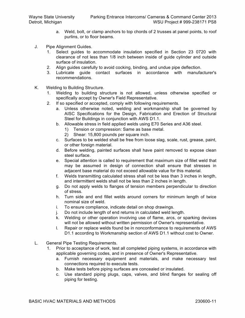
Wayne State University Parking Entrance Intercoms/ Cameras & Command Center 2013 Detroit, Michigan WSU Project # 999-238171 PS8
BASIC HVAC MATERIALS AND METHODS 230600-11
a. Weld, bolt, or clamp anchors to top chords of 2 trusses at panel points, to roof purlins, or to floor beams.
J. Pipe Alignment Guides. 1. Select guides to accommodate insulation specified in Section 23 0720 with
clearance of not less than 1/8 inch between inside of guide cylinder and outside surface of insulation.
2. Align guides carefully to avoid cocking, binding, and undue pipe deflection. 3. Lubricate guide contact surfaces in accordance with manufacturer's
recommendations.
K. Welding to Building Structure. 1. Welding to building structure is not allowed, unless otherwise specified or
specifically accept by Owner's Field Representative. 2. If so specified or accepted, comply with following requirements.
a. Unless otherwise noted, welding and workmanship shall be governed by AISC Specifications for the Design, Fabrication and Erection of Structural Steel for Buildings in conjunction with AWS D1.1.
b. Allowable stress in field applied welds using E70 Series and A36 steel. 1) Tension or compression: Same as base metal. 2) Shear: 15,800 pounds per square inch.
c. Surfaces to be welded shall be free from loose slag, scale, rust, grease, paint, or other foreign material.
d. Before welding, painted surfaces shall have paint removed to expose clean steel surface.
e. Special attention is called to requirement that maximum size of fillet weld that may be assumed in design of connection shall ensure that stresses in adjacent base material do not exceed allowable value for this material.
f. Welds transmitting calculated stress shall not be less than 3 inches in length, and intermittent welds shall not be less than 2 inches in length.
g. Do not apply welds to flanges of tension members perpendicular to direction of stress.
h. Turn side and end fillet welds around corners for minimum length of twice nominal size of weld.
i. To ensure compliance, indicate detail on shop drawings. j. Do not include length of end returns in calculated weld length. k. Welding or other operation involving use of flame, arcs, or sparking devices
will not be allowed without written permission of Owner's representative. l. Repair or replace welds found be in nonconformance to requirements of AWS
D1.1 according to Workmanship section of AWS D1.1 without cost to Owner.
L. General Pipe Testing Requirements. 1. Prior to acceptance of work, test all completed piping systems, in accordance with
applicable governing codes, and in presence of Owner's Representative. a. Furnish necessary equipment and materials, and make necessary test
connections required to execute tests. b. Make tests before piping surfaces are concealed or insulated. c. Use standard piping plugs, caps, valves, and blind flanges for sealing off
piping for testing.
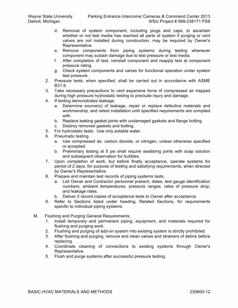
Wayne State University Parking Entrance Intercoms/ Cameras & Command Center 2013 Detroit, Michigan WSU Project # 999-238171 PS8
BASIC HVAC MATERIALS AND METHODS 230600-12
d. Removal of system component, including plugs and caps, to ascertain whether or not test media has reached all parts of system if purging or vent valves are not installed during construction, may be required by Owner's Representative.
e. Remove components from piping systems during testing whenever component may sustain damage due to test pressure or test media.
f. After completion of test, reinstall component and reapply test at component pressure rating.
g. Check system components and valves for functional operation under system test pressure.
2. Pressure tests, when specified, shall be carried out in accordance with ASME B31.9.
3. Take necessary precautions to vent expansive force of compressed air trapped during high pressure hydrostatic testing to preclude injury and damage.
4. If testing demonstrates leakage. a. Determine source(s) of leakage, repair or replace defective materials and
workmanship, and retest installation until specified requirements are complied with.
b. Replace leaking gasket joints with undamaged gaskets and flange bolting. c. Destroy removed gaskets and bolting.
5. For hydrostatic tests: Use only potable water. 6. Pneumatic testing.
a. Use compressed air, carbon dioxide, or nitrogen, unless otherwise specified or accepted.
b. Preliminary testing at 5 psi shall require swabbing joints with soap solution and subsequent observation for bubbles.
7. Upon completion of work, but before finally acceptance, operate systems for period of 2 days, for purpose of testing and satisfying requirements, when directed by Owner's Representative.
8. Prepare and maintain test records of piping systems tests. a. List Owner and Contractor personnel present, dates, test gauge identification
numbers, ambient temperatures, pressure ranges, rates of pressure drop, and leakage rates.
b. Deliver 2 record copies of acceptance tests to Owner after acceptance. 9. Refer to Sections listed under heading, Related Sections, for requirements
specific to individual piping systems.
M. Flushing and Purging General Requirements. 1. Install temporary and permanent piping, equipment, and materials required for
flushing and purging work. 2. Flushing and purging of add-on system into existing system is strictly prohibited. 3. After flushing and purging, remove and clean valves and strainers of debris before
replacing. 4. Coordinate cleaning of connections to existing systems through Owner's
Representative. 5. Flush and purge systems after successful pressure testing.

Wayne State University Parking Entrance Intercoms/ Cameras & Command Center 2013 Detroit, Michigan WSU Project # 999-238171 PS8
BASIC HVAC MATERIALS AND METHODS 230600-13
3.2 FIELD QUALITY CONTROL
A. Check that pressure, temperature, and flow measuring devices are placed in correct locations. Make modifications to ensure compliance.
B. Check scale ranges of individual instruments. Expected normal reading: Near middle of scale. Replace instruments not conforming to this requirement.
C. Verify that piping systems have been flushed and filled.
D. Check valve packings. Adjust or replace leaking valve packings.
E. Verify piping alignment at flexible connections or expansion joints, in hot and cold condition. Correct misalignment, where joints are found to squirm.
END OF SECTION 230600

Wayne State University Parking Entrance Intercoms/ Cameras & Command Center 2013 Detroit, Michigan WSU Project # 999-238171 PS8
HVAC INSULATION 230720-1
SECTION 230720 - HVAC INSULATION PART 1 GENERAL 1.1 RELATED REQUIREMENTS
A. Section 23 0513 - Common Work Results for HVAC Equipment.
B. Section 23 0600 - Basic HVAC Materials and Methods.
C. Section 23 1008 - Hangers and Supports for HVAC.
D. Section 23 3100 - HVAC Ducts and Casings. 1.2 REFERENCE STANDARDS
A. ASTM B749 - Standard Specification for Lead and Lead Alloy Strip, Sheet, and Plate Products; 2003.
B. ASTM C36/C36M - Standard Specification for Gypsum Wallboard; 2001.
C. ASTM C533 - Standard Specification for Calcium Silicate Block and Pipe Thermal Insulation ; 2004.
D. ASTM C534 - Standard Specification for Preformed Flexible Elastomeric Cellular Thermal Insulation in Sheet and Tubular Form ; 2003.
E. ASTM C547 - Standard Specification for Mineral Fiber Pipe Insulation ; 2003.
F. ASTM C553 - Standard Specification for Mineral Fiber Blanket Thermal Insulation for Commercial and Industrial Applications; 2002.
G. ASTM C612 - Standard Specification for Mineral Fiber Block and Board Thermal Insulation ; 2004.
H. ASTM E84 - Standard Test Method for Surface Burning Characteristics of Building Materials ; 2005.
I. ASTM E96 - Standard Test Methods for Water Vapor Transmission of Materials ; 2000.
J. NFPA 258 - Standard Research Test Method for Determining Smoke Generation of Solid Materials ; 2001.
1.3 SUBMITTALS
A. Refer to Section 01 3000 – Administrative Requirements, for submittal procedures.
B. For Information.

Wayne State University Parking Entrance Intercoms/ Cameras & Command Center 2013 Detroit, Michigan WSU Project # 999-238171 PS8
HVAC INSULATION 230720-2
1. Product data. a. Each product and component.
1.4 WARRANTY
A. Refer to Section 01 7700 – Closeout Procedures, for additional warranty requirements. 1.5 SCHEDULES
A. 1. Refrigeration piping (suction only), indoor. a. Type PP-1. b. Thickness: 1 inch on 1 inch and smaller pipe. 1-1/2 inches on 1-1/4 inch and
larger pipe. 2. Refrigeration piping (suction only), outdoor.
a. Type PP-1 with JJ-1. b. Thickness: 1-1/2 inches on 1 inch and smaller pipe. 2 inches on 1-1/4 inch
and larger pipe.
B. Ductwork Insulation. 1. Ducts for intake of outdoor air.
a. Type DD-1. b. Thickness: 1-1/2 inches.
2. Mixed air plenums and coil housings. a. Type DD-1. b. Thickness: 1-1/2 inches.
3. Air conditioning supply ducts (concealed). a. Type DD-2. b. Thickness: 1-1/2 inches.
5. Return air ducts (concealed). a. Type DD-2. b. Thickness: 1-1/2 inches.
9. Duct Liner (to be used in return air sound boots only). a. Type DD-5.
PART 2 PRODUCTS 2.1 SYSTEM DESCRIPTION
A. Drawings indicate equipment locations, related layouts, and general design of systems specified under Division 23.
B. Include thermal insulation for scheduled systems.
C. Unless otherwise specified or indicated, insulate surfaces in accordance with insulation schedules specified.
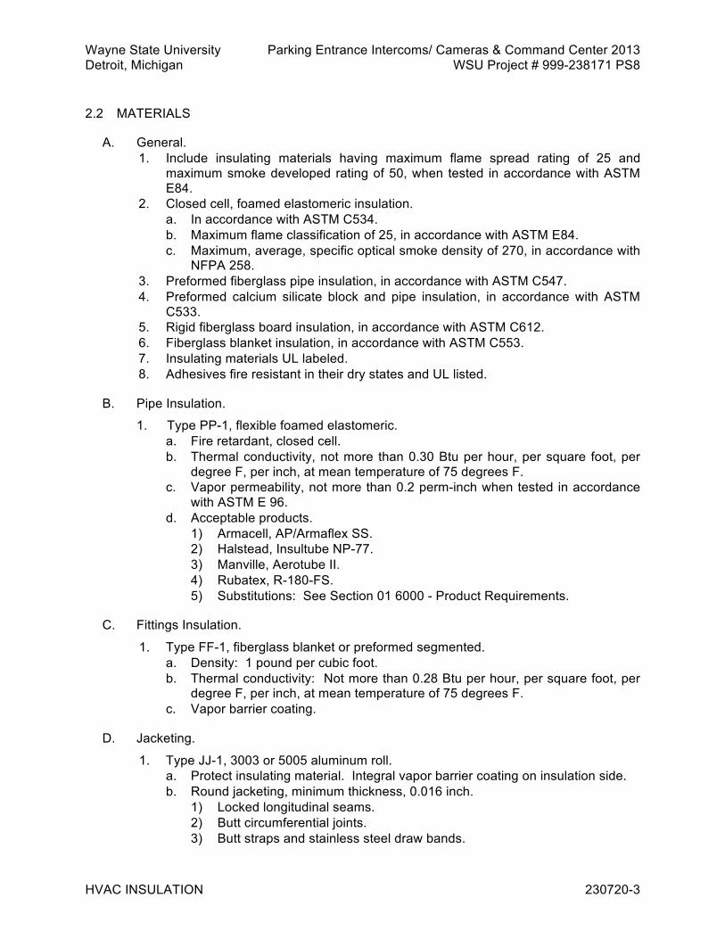
Wayne State University Parking Entrance Intercoms/ Cameras & Command Center 2013 Detroit, Michigan WSU Project # 999-238171 PS8
HVAC INSULATION 230720-3
2.2 MATERIALS
A. General. 1. Include insulating materials having maximum flame spread rating of 25 and
maximum smoke developed rating of 50, when tested in accordance with ASTM E84.
2. Closed cell, foamed elastomeric insulation. a. In accordance with ASTM C534. b. Maximum flame classification of 25, in accordance with ASTM E84. c. Maximum, average, specific optical smoke density of 270, in accordance with
NFPA 258. 3. Preformed fiberglass pipe insulation, in accordance with ASTM C547. 4. Preformed calcium silicate block and pipe insulation, in accordance with ASTM
C533. 5. Rigid fiberglass board insulation, in accordance with ASTM C612. 6. Fiberglass blanket insulation, in accordance with ASTM C553. 7. Insulating materials UL labeled. 8. Adhesives fire resistant in their dry states and UL listed.
B. Pipe Insulation.
1. Type PP-1, flexible foamed elastomeric. a. Fire retardant, closed cell. b. Thermal conductivity, not more than 0.30 Btu per hour, per square foot, per
degree F, per inch, at mean temperature of 75 degrees F. c. Vapor permeability, not more than 0.2 perm-inch when tested in accordance
with ASTM E 96. d. Acceptable products.
1) Armacell, AP/Armaflex SS. 2) Halstead, Insultube NP-77. 3) Manville, Aerotube II. 4) Rubatex, R-180-FS. 5) Substitutions: See Section 01 6000 - Product Requirements.
C. Fittings Insulation.
1. Type FF-1, fiberglass blanket or preformed segmented. a. Density: 1 pound per cubic foot. b. Thermal conductivity: Not more than 0.28 Btu per hour, per square foot, per
degree F, per inch, at mean temperature of 75 degrees F. c. Vapor barrier coating.
D. Jacketing.
1. Type JJ-1, 3003 or 5005 aluminum roll. a. Protect insulating material. Integral vapor barrier coating on insulation side. b. Round jacketing, minimum thickness, 0.016 inch.
1) Locked longitudinal seams. 2) Butt circumferential joints. 3) Butt straps and stainless steel draw bands.

Wayne State University Parking Entrance Intercoms/ Cameras & Command Center 2013 Detroit, Michigan WSU Project # 999-238171 PS8
HVAC INSULATION 230720-4
4) Include butt straps with high temperature resistant weatherproof sealant. c. Rectangular jacketing, minimum thickness, 0.032 inch. d. Acceptable products.
1) Childers, Lock-On, Ell-Jacs and Tee-Jacs. 2) Pabco, Surefit. 3) Substitutions: See Section 01 6000 - Product Requirements.
E. Ductwork and Sheet Metal Insulation.
1. Type DD-1, rigid fiberglass board. a. Density: 6 pounds per cubic foot. b. Jacket: UL rated, factory applied, flame retardant, foil-faced reinforced, kraft
vapor barrier. c. Thermal conductivity: Not more than 0.22 Btu per hour, per square foot, per
degree F, per inch, at 60 degrees F. d. Acceptable products.
1) Knauf, Insulation Board 6 PCF with FSK. 2) Manson, AK Board with FSK. 3) Manville, Type 817 with FSK. 4) Owens-Corning, 705 Series with FRK. 5) Substitutions: See Section 01 6000 - Product Requirements.
2. Type DD-2, flexible, fiberglass duct blanket covering. a. Thermal conductivity: Not more than 0.26 Btu per hour, per square foot, per
degree F, per inch, at 75 degrees F. b. Jacket: UL rated, factory applied, vapor barrier. c. Laminated, reinforced aluminum foil faced with flame resistant kraft paper. d. Maximum vapor permeability rating: 0.02 perm. e. Acceptable manufacturers.
1) CertainTeed, Standard Duct Wrap with FSK. 2) Knauf, Duct Wrap 1.0 PCF with FSK. 3) Manville, R-Series Microlite with FSKL. 4) Owens-Corning, Faced Duct Wrap Insulation, Commercial Grade Type
100. 5) Substitutions: See Section 01 6000 - Product Requirements.
3. Type DD-5, Duct Liner. a. Flexible Glass Fiber, ASTM C1071. b. Thickness: 2 inches. c. Type II, ‘k’ value of 0.23 at 75 degrees F d. 3.0 lb/cu ft minimum density e. Coating air side for maximum 4,000 feet per minute air velocity. f. The airstream surface must be protected with a durable polyacrylate
copolymer emulsion specifically formulated to: 1) Not support the growth of fungus or bacteria, when tested in accordance
with the test method for fungi resistance in ASTM D 5590 with “0” growth rating.
2) Act as a fungicidal protective coating: water based, VOC < 50 g/l. Fungicidal coating must be EPA registered for use in HVAC duct systems. Manufacturer: H.B. Fuller Construction Products Inc., Foster 40-20 (white) or 40-30 (black) Fungicidal Protective Coating or approved

Wayne State University Parking Entrance Intercoms/ Cameras & Command Center 2013 Detroit, Michigan WSU Project # 999-238171 PS8
HVAC INSULATION 230720-5
equal. Coatings may also be used to repair damage to duct liner insulation.
g. Acceptable fiberglass insulation manufacturers. 1) Knauf, Rigid Plenum Liner. 2) Manville, Linacoustic R Liner Board. 3) Owens-Corning, Duct Liner Board. 4) Armacell North America. 5) 3M fire Protection Products (Fire Barrier Duct Wrap 615+) 6) Substitutions: See Section 01 6000 - Product Requirements.
F. Cements, Adhesives, and Coatings.
1. Insulating and finishing cement. a. Acceptable products.
1) Celotex, MW-1. 2) Pabco, Pabcote. 3) Fibrex, FBX Superkote. 4) Substitutions: See Section 01 6000 - Product Requirements.
2. Lap adhesive and finish coating for nonvapor barrier applications. a. Acceptable products.
1) Childers, CP-50A. 2) Foster, 30-04. 3) Marathon, 102. 4) Substitutions: See Section 01 6000 - Product Requirements.
3. Contact adhesive manufacturer shall be same as insulation manufacturer. a. Acceptable products.
1) Armacell, 520. 2) Halstead, Instant Bonding Adhesive. 3) Manville, J-M 57. 4) Rubatex, 373. 5) Substitutions: See Section 01 6000 - Product Requirements.
4. Vapor barrier lap adhesive and surfacing adhesive. a. Acceptable products.
1) Childers, CP-82. 2) Foster, 85-20. 3) Marathon, 225. 4) Substitutions: See Section 01 6000 - Product Requirements.
5. Vapor barrier coatings. a. Acceptable products.
1) Marathon, 501. 2) Childers, CP-30 or CP-32. 3) Foster, 30-35. 4) Substitutions: See Section 01 6000 - Product Requirements.

Wayne State University Parking Entrance Intercoms/ Cameras & Command Center 2013 Detroit, Michigan WSU Project # 999-238171 PS8
HVAC INSULATION 230720-6
PART 3 EXECUTION 3.1 INSTALLATION
A. General Requirements. 1. Install to present a neat, clean appearance. 2. Apply only after surfaces have been cleaned, inspected, and tested. 3. Apply neatly, tightly, with unbroken lengths, and with ends of sections firmly
butted together. 4. At joints, lap insulating jackets and cement in position. 5. Sectional covering shall be uniform. 6. Where required material thickness is not available, layer insulation, staggering
butt joints. 7. Do not dilute surface finishes and adhesives. 8. Apply surface finishes and adhesives in accordance with manufacturer's
instructions. 9. Do not apply sealing coats until volatiles have dissipated, and until cements and
adhesives have thoroughly dried. 10. Unless otherwise specified, do not apply second or multiple coats until previous
coats have thoroughly dried. 11. Do not use flame or spark producing equipment in areas where adhesives,
mastics, sealants, or coatings containing volatiles are stored or being applied. 12. Maintain integrity of vapor barriers. Do not use fasteners to secure vapor barrier
insulation, which penetrate or damage vapor barrier. 13. Butt insulation to building construction and to angle iron stops. Where vapor seals
or similar facings are required, extend and seal to building construction or angle. 14. Surfaces to be insulated shall be considered concealed where located in furred
spaces or above suspended ceilings, other work shall be considered exposed. 15. Restore to original likeness existing insulation damaged during progress of the
work.
B. Pipe and Fittings Insulation.
1. General application notes. a. Insulate each pipe individually. Gang insulation of piping groups is
unacceptable. b. Place longitudinal joints on the least conspicuous side of pipe. c. Extend insulation on piping through sleeves. d. Install insulation to conform to a uniform diameter. e. Insulate fittings, flanges, and valves to a thickness equal to the insulation on
adjacent piping. f. Omit insulation on rubber expansion joints and rubber vibration isolation joints
of hot water services. g. At uncovered joints and fittings: Taper ends of insulation with cement before
wrapping. Construct tapered ends adjacent to bolted joints to permit removal of bolts without damaging insulation.
h. Seal insulation and jacketing cut during installation of pipe anchors, with insulating cement.

Wayne State University Parking Entrance Intercoms/ Cameras & Command Center 2013 Detroit, Michigan WSU Project # 999-238171 PS8
HVAC INSULATION 230720-7
2. Type PP-1 insulation. a. Install insulation and seal longitudinal, self-sealing laps in accordance with
manufacturer's instructions. b. Where vapor barrier is required, wrap circumferential joints with vapor barrier
pressure sensitive adhesive tape, overlapping insulation by 2 inches.
5. Type FF-1 insulation. a. Insulate fittings, flanges, and valves to a thickness equal to covering on
adjacent piping. b. Where preformed, segmented pipe type insulation is used, secure insulation
with 20 gauge galvanized steel wire. c. Cover blanket or segmented insulation with a smooth coat of insulating
cement. d. Over the coat of insulating cement, apply a layer of open weave glass cloth
fabric, embedded between 2 flood coats of vapor barrier coating. e. Overlap fabric not less than 2 inches onto adjacent pipe insulation.
C. Jacketing.
1. Type JJ-1. a. Install round jacketing and attach butt straps and draw bands in accordance
with manufacturer's instructions. b. Lap rectangular jacketing not less than 2 inches on longitudinal and
transverse joints. Lap top jacketing over side jacketing. Seal joints with manufacturer's standard weather and heat resistant sealant. Attach jacketing with stainless steel sheet metal screws and lead washers, or galvanized angle iron hoops.
D. Ductwork and Sheet Metal Insulation.
1. General. a. Unless otherwise specified or indicated, insulation for ductwork includes
insulation for plenums, adapters, transitions, collars, boots, standing seams, stiffeners, angle rings, flanges, and similar components not factory insulated or lined.
b. Prior to installation of thermal insulation to faces of sheet metal fabrication inaccessible once installed, install jacket flaps on exposed edges, for overlapping onto accessible portions of insulation.
c. At sheet metal joints, maintain vapor barrier on inaccessible insulation by returning and cementing insulation jacketing to sheet metal.
d. Where insulation is specified for sheet metal construction located adjacent to lined or covered system portions, overlap lining or lagging by not less than 24 inches.
2. Type DD-1. a. Install angle iron frames, or approved stops, at doors in plenums or similar
openings. b. Finish edges and seams at visible locations in a neat manner. c. Impale insulation on pins. Secure insulation mechanically to sheet metal
work in an approved manner. On underside ductwork greater than 24 inches wide space fasteners on not greater than 18 inch centers. Hold insulation in place with speed nuts or clips in accordance with manufacturer's

Wayne State University Parking Entrance Intercoms/ Cameras & Command Center 2013 Detroit, Michigan WSU Project # 999-238171 PS8
HVAC INSULATION 230720-8
recommendations. Cut off protruding ends of fasteners flush with speed clips.
d. Cover insulation joints with 3 inch wide vapor barrier tape, sealed with vapor barrier lap adhesive.
e. Treat punctures in facing of insulation in same manner as joints. f. After insulation is installed on indoor ductwork seal and cover joints and
punctures with tack coat of vapor barrier coating at coverage rate of 40 to 50 square feet per gallon. Embed into wet tack coat, layer of fiberglass reinforcing cloth overlapping by 2 inches at seams. Smooth cloth, eliminating wrinkles. Apply final vapor barrier coating using same coverage rate not later than 1 hour after tack coat.
3. Type DD-2. a. Attach insulation to sheet metal work with surfacing adhesive using
approximately 50 percent coverage of adhesive, or impale insulation on pins, mechanically secured to sheet metal work in an approved manner.
b. Hold in place with speed nuts or clips in accordance with manufacturer's recommendations.
c. At joints: Cut fiberglass mat back by 4 inches, on 1 of 2 abutting sections of insulation. Fold remaining vapor barrier jacket flap to double thickness. Apply full coverage of vapor barrier lap adhesive to vapor barrier jacket of adjoining insulation section and staple.
d. Apply a 4 inch wide brush coat of vapor barrier lap adhesive over joint. 1) Center over folded edge of jacket flap. 2) Apply additional vapor barrier lap adhesive where staple penetrations
remain exposed or where fishmouths are evident.
4. Type DD-5 sound isolating duct cover. a. Acoustically isolate ductwork indicated on drawings. b. Extend covering over entire duct perimeter and over duct lengths indicated. c. Butt and seal adjoining edges of laminates with a non-hardening sealant. d. On ducts requiring thermal insulation: Extend vapor barrier over duct lengths
enclosed by sound isolating duct cover. e. When using lead sheet instead of gypsum board: Overlap sheets 2 inches at
seams. Spot burn and seal with duct tape. Secure with steel straps on 1 foot centers.
END OF SECTION 230720

Wayne State University Parking Entrance Intercoms/ Cameras & Command Center 2013 Detroit, Michigan WSU Project # 999-238171 PS8
HANGERS AND SUPPORTS FOR HVAC 231008-1
SECTION 231008 - HANGERS AND SUPPORTS FOR HVAC PART 1 GENERAL 1.1 REFERENCE STANDARDS
A. AISC (COMM) - Commentary on the Specification for Structural Steel Buildings--Allowable Stress Design and Plastic Design ; 1989.
B. ASME B31.1 - Power Piping ; 2007 (ANSI/ASME B31.1).
C. AWS D1.1/D1.1 M - Structural Welding Code - Steel ; 2008. 1.2 SUBMITTALS
A. See Section 01 3000 – Administrative Requirements, for submittal procedures.
B. For Review. 1. Shop drawings.
a. Pipe hanger and support installation details, including details and locations of seismic or sway bracing, pipe anchors, and anchor bracing.
b. Include dimensioned location and method of attachment to building structure. c. Where pipe hangers cannot be hung from building structure, submit proposed
method of installing additional structural steel that connects to the building structure.
1.3 QUALITY ASSURANCE
A. Qualifications. 1. Supplemental steel welding procedures, in accordance with section, Qualification,
of AWS D1.1. 2. Only welders who have successfully passed examination for this class of work
shall be employed to execute structural strength welds. 3. Examination shall have been within the past six months, unless welder has been
making this type of weld after passing test within two years, as specified under qualification procedures of AWS D1.1.
1.4 DELIVERY, STORAGE, AND HANDLING
A. See Section 01 6000 – Product Requirements, for transportation, storage, and handling requirements.

Wayne State University Parking Entrance Intercoms/ Cameras & Command Center 2013 Detroit, Michigan WSU Project # 999-238171 PS8
HANGERS AND SUPPORTS FOR HVAC 231008-2
PART 2 PRODUCTS 2.1 MANUFACTURED UNITS
A. Adjustable Swivel Ring Hangers. 1. Heavy steel construction with swivel nut and locknut. 2. Acceptable products.
a. B-Line, Fig. B3170. b. Carpenter and Paterson, Fig. 800. c. Anvil International Inc. (Grinnell), Fig. 70. d. Michigan Hanger Co., No. 100. e. Substitutions: See Section 01 6000 - Product Requirements.
B. Clevis Hangers. 1. Heavy steel with adjustable nut and locknut. 2. Include spreaders on cross bolts of hangers for pipe sized 10 inches and larger. 3. Acceptable products.
a. B-Line, Fig. B3100. b. Carpenter and Paterson, Fig. 100. c. Anvil International Inc. (Grinnell), Fig. 260. d. Michigan Hanger Co., No. 400. e. Substitutions: See Section 01 6000 - Product Requirements.
C. V-Clevis Hangers. 1. Heavy steel with adjustable nut and locknut. 2. Acceptable products.
a. B-Line, Fig. B3106. b. Carpenter and Paterson, Fig. 200VT. c. Michigan Hanger Co., No. 104. d. Substitutions: See Section 01 6000 - Product Requirements.
D. Single-Rod Roller Hanger. 1. Steel frame, cast iron roller, and steel roller rod. 2. Acceptable products.
a. B-Line, Fig. B3110. b. Carpenter and Paterson Fig. 140. c. Anvil International Inc. (Grinnell), Fig. 181. d. Michigan Hanger Co., No. 610. e. Substitutions: See Section 01 6000 - Product Requirements.
E. Two-Rod Roller Hanger. 1. Cast iron roller, steel roller rod, and malleable iron or cast iron sockets, without
hanger rod. 2. Acceptable products.
a. B-Line, Fig. B3114. b. Carpenter and Paterson, Fig. 142. c. Anvil International Inc. (Grinnell), Fig. 171.

Wayne State University Parking Entrance Intercoms/ Cameras & Command Center 2013 Detroit, Michigan WSU Project # 999-238171 PS8
HANGERS AND SUPPORTS FOR HVAC 231008-3
d. Michigan Hanger Co., No. 605. e. Substitutions: See Section 01 6000 - Product Requirements.
F. Adjustable, Two-Rod Roller Hanger. 1. Cast iron roller, steel roller rod, malleable iron or cast iron sockets, and threaded
hanger rods with nuts. 2. Acceptable products.
a. B-Line, Fig. B3122. b. Carpenter and Paterson, Fig. 109. c. Anvil International Inc. (Grinnell), Fig. 177. d. Michigan Hanger Co., No. 620. e. Substitutions: See Section 01 6000 - Product Requirements.
G. Protection Shields. 1. Minimum 18 gauge thick, 180 degree, galvanized steel shield with flared ends and
centering ribs.
H. Preinsulated Hanger Inserts. 1. Hanger inserts consist of two 180 degree segments of 100 psi average
compressive strength insulation of same thickness as adjoining pipe insulation. a. Where manufacturer recommends or drawings indicate, include wedge
shaped insert in bottom half, consisting of 600 psi minimum compressive strength calcium silicate.
b. Length of hanger insert is scheduled on drawings. 2. Protect each half of hanger insert by adhering galvanized sheet metal shield to
saddle. a. Shield length and gauge thickness is scheduled on drawings. b. Where indicated or recommended by manufacturer, include heavy-duty load
bearing plate on bottom of metal shield. c. Area of high density insert and pipe bearing support surface of shield shall be
as scheduled on drawings or as recommended by manufacturer. d. Acceptable products.
1) American Mechanical Insulation Sales Inc.: AMIS 200 Calmax. 2) B-Line: Figures B3380 through B3384. 3) Carpenter and Paterson: 465 CVB. 4) Michigan Hanger Co.: Nos. 126 and 127. 5) Pipe Shields Incorporated: Series A1000 through A9000. 6) Value Engineered Products, Inc.: Pro-Shield Series. 7) Substitutions: See Section 01 6000 - Product Requirements.
3. For insulated copper piping with Type PP-2 insulation, use preinsulated hanger inserts as manufactured by Klo-Sure.
I. Trapeze Hangers. 1. Two-structural channels, back to back, with spacers welded at least on each end,
at top and bottom of channels. 2. Size channels with consideration to total weight to be supported, overall span
between hanger rods, and so as not to deflect more than 1/240 of span (5/16 inch in 6 feet 3 inches).
3. Assume piping to be supported is full of water.

Wayne State University Parking Entrance Intercoms/ Cameras & Command Center 2013 Detroit, Michigan WSU Project # 999-238171 PS8
HANGERS AND SUPPORTS FOR HVAC 231008-4
4. Submit detailed drawings for Owner's Field Representative review.
J. Beam Clamps for Pipe 2 Inches and Smaller. 1. Side type.
a. Acceptable products. 1) B-Line: Fig. B3045. 2) Carpenter and Paterson: Fig. 18. 3) Supply Sales (Grinnell): Fig. 217. 4) Michigan Hanger Co.: No. 367. 5) Substitutions: See Section 01 6000 - Product Requirements.
2. Side I type. a. Acceptable products.
1) Carpenter and Paterson: Fig. 45. 2) Supply Sales (Grinnell): Fig. 225. 3) Substitutions: See Section 01 6000 - Product Requirements.
3. Adjustable type. a. Acceptable products.
1) B-Line: Fig. B3040. 2) Carpenter and Paterson: Fig. 14. 3) Supply Sales (Grinnell): Fig. 14. 4) Michigan Hanger Co.: No. 363. 5) Substitutions: See Section 01 6000 - Product Requirements.
K. I-Beam Clamps. 1. For pipe sized 2-1/2 through 20 inches, with swing nuts.
a. Acceptable products. 1) B-Line: Fig. B3050. 2) Michigan Hanger: Model 361. 3) Carpenter and Paterson: Fig. 15. 4) Supply Sales (Grinnell): Fig. 133 and 134. 5) Substitutions: See Section 01 6000 - Product Requirements.
L. Beam Clamps. 1. For pipe sized 24 and 30 inches, with weldless eye nuts.
a. Acceptable products. 1) B-Line: Fig. B3291 through Fig. B3297. 2) Carpenter and Paterson: Fig. 297. 3) Supply Sales (Grinnell): Fig. 292. 4) Substitutions: See Section 01 6000 - Product Requirements.
M. Hanger Rods. 1. Threaded, hot rolled, steel rod conforming to ASTM A 36 or A 575. 2. Hanger rod may be continuously threaded. 3. Use of rod couplings is prohibited.
N. Hanger Rod Anchors. 1. Suitable for supporting hanger rods in reinforced concrete construction.
a. For HVAC piping systems, ductwork and equipment. 1) Mechanical expansion type.

Wayne State University Parking Entrance Intercoms/ Cameras & Command Center 2013 Detroit, Michigan WSU Project # 999-238171 PS8
HANGERS AND SUPPORTS FOR HVAC 231008-5
2) Acceptable products. (a) Hilti: Kwik Bolt TZ. (b) Powers Fasteners: Power-Stud + SD2. (c) Simpson Strong Tie: Strong-Bolt. (d) Substitutions: See Section 01 6000 - Product Requirements.
2.2 MATERIALS
A. Pipe Hanger and Supporting Materials. 1. Represent minimum requirements for mechanical work in general.
PART 3 EXECUTION 3.1 INSTALLATION
A. Install hanger and supporting materials in accordance with specified requirements, and in accordance with seismic requirements dictated by local codes and governing authorities. 1. Submit typical details and locations for review.
B. C-clamps without retainer clips and heat-treated spring steel clips that bite into building steel are prohibited as means of fastening pipe hangers to building structure.
C. Clamps that result in eccentric loads (twisting moments) on structural members of building, except for piping sized 2 inches and smaller, are also prohibited.
D. Support piping from building structural frame, not from roof deck, permanent metal forms for concrete floors, reinforced concrete slab (unless indicated otherwise), or from other pipe, duct, or equipment.
E. Contractor's attention is directed to drawing details and building structural framing layout that may require hanger spacing more frequently than spacings shown in table below. 1. Loading at any support point shall not exceed 1000 pounds, unless specifically
indicated otherwise. Screwed or welded steel pipe (liquid or vapor)
Pipe Size Maximum Hanger Spacing Minimum Rod Size 1/2 to 1 inch 8 feet 3/8 inch 1-1/4 through 2 inches 10 feet 3/8 inch 2-1/2 to 3 inches 12 feet 1/2 inch 4 inches 12 feet 5/8 inch 6 inches 12 feet 3/4 inch 8 and 12 inches 12 feet 7/8 inch
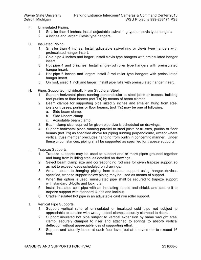
Wayne State University Parking Entrance Intercoms/ Cameras & Command Center 2013 Detroit, Michigan WSU Project # 999-238171 PS8
HANGERS AND SUPPORTS FOR HVAC 231008-6
F. Uninsulated Piping. 1. Smaller than 4 inches: Install adjustable swivel ring type or clevis type hangers. 2. 4 inches and larger: Clevis type hangers.
G. Insulated Piping. 1. Smaller than 4 inches: Install adjustable swivel ring or clevis type hangers with
preinsulated hanger insert. 2. Cold pipe 4 inches and larger: Install clevis type hangers with preinsulated hanger
insert. 3. Hot pipe 4 and 5 inches: Install single-rod roller type hangers with preinsulated
hanger insert. 4. Hot pipe 6 inches and larger: Install 2-rod roller type hangers with preinsulated
hanger insert. 5. On roof, sized 1 inch and larger: Install pipe rolls with preinsulated hanger insert.
H. Pipes Supported Individually From Structural Steel. 1. Support horizontal pipes running perpendicular to steel joists or trusses, building
roof purlins or floor beams (not T's) by means of beam clamps. 2. Beam clamps for supporting pipe sized 2 inches and smaller, hung from steel
joists or trusses, purlins or floor beams, (not T's) may be one of following. a. Side beam clamp. b. Side I-beam clamp. c. Adjustable beam clamp.
3. Beam clamp size required for given pipe size is scheduled on drawings. 4. Support horizontal pipes running parallel to steel joists or trusses, purlins or floor
beams (not T's) as specified above for piping running perpendicular, except where vertical truss member precludes hanging from purlin in concentric manner. Under these circumstances, piping shall be supported as specified for trapeze supports.
I. Trapeze Supports. 1. Trapeze supports may be used to support one or more pipes grouped together
and hung from building steel as detailed on drawings. 2. Select beam clamp size and corresponding rod size for given trapeze support so
as not to exceed loads scheduled on drawings. 3. As an option to hanging piping from trapeze support using hanger devices
specified, trapeze support below piping may be used as means of support. 4. When this option is used, uninsulated pipe shall be secured to trapeze support
with standard U-bolts and locknuts. 5. Install insulated cold pipe with an insulating saddle and shield, and secure it to
trapeze support with standard U-bolt and locknut. 6. Cradle insulated hot pipe in an adjustable cast iron roller support.
J. Vertical Pipe Supports. 1. Support vertical runs of uninsulated or insulated cold pipe not subject to
appreciable expansion with wrought steel clamps securely clamped to risers. 2. Support insulated hot pipe subject to vertical expansion by same wrought steel
clamp, securely clamped to riser and attached to springs to absorb vertical deflection without appreciable loss of supporting effort.
3. Support and laterally brace at each floor level, but at intervals not to exceed 16 feet.

Wayne State University Parking Entrance Intercoms/ Cameras & Command Center 2013 Detroit, Michigan WSU Project # 999-238171 PS8
HANGERS AND SUPPORTS FOR HVAC 231008-7
K. Where necessary for proper system functioning, brace piping and supports against reaction sway and vibration.
L. For concentrated loads, e.g., valves, reduce allowable span proportionately.
M. Vertical risers shall be supported independently of connected horizontal piping whenever practical, with fixed or spring supports at base and at intervals to accommodate system range of load and thermal conditions, and shall be guided for lateral stability. 1. Only one rigid support shall be installed for risers subjected to expansion at
approximately 1/3 point from top, unless otherwise indicated. 2. For horizontal piping contiguous to moving risers, two supports nearest to riser
shall be spring supports, unless otherwise indicated.
N. After piping systems have been installed, tested, and placed in satisfactory operation, firmly tighten hanger rod nut and jam nut and upset threads to prevent the movement of fasteners.
O. Welding to Building Structure. 1. Welding to building structure is not allowed, unless otherwise specified or
specifically accepted by Owner's Field Representative 2. If so specified or accepted, comply with following requirements.
a. Unless otherwise noted, welding and workmanship shall be governed by AISC Specifications for the Design, Fabrication and Erection of Structural Steel for Buildings in conjunction with AWS D1.1.
b. Allowable stresses in field applied welds using E70 Series and A36 steel. 1) Tension or compression, same as base metal.
(a) Shear, 15,800 pounds per square inch.
P. Surfaces to be welded shall be free from loose slag, scale, rust, grease, paint, or other foreign material.
Q. Before welding, painted surfaces shall have paint removed to expose clean steel surface. 1. Special attention is called to requirement that maximum size of fillet weld that may
be assumed in design of connection shall ensure that stresses in adjacent base material do not exceed allowable value for this material.
R. No welds transmitting calculated stress shall be less than 3 inches in length, and no intermittent welds shall be less than 2 inches in length.
S. No welds shall be applied to flanges of tension members perpendicular to direction of stress.
T. Turn side and end fillet welds around corners for minimum length of twice nominal size of weld.
U. Length of end returns is not to be included in calculated weld length.
V. No welding or other operation involving use of flame, arcs, or sparking devices will be allowed without written permission of Owner's Representative.
Wayne State University Parking Entrance Intercoms/ Cameras & Command Center 2013 Detroit, Michigan WSU Project # 999-238171 PS8
HANGERS AND SUPPORTS FOR HVAC 231008-8
W. Welds found to be in nonconformance to requirements of AWS D1.1 shall be repaired or replaced according to workmanship section of AWS D1.1 without cost to Owner.
END OF SECTION 231008

Wayne State University Parking Entrance Intercoms/ Cameras & Command Center 2013 Detroit, Michigan WSU Project # 999-238171 PS8
HVAC DUCTS AND CASINGS 233100-1
SECTION 233100 - HVAC DUCTS AND CASINGS PART 1 GENERAL 1.1 RELATED REQUIREMENTS
A. Section 23 0513 - Common Work Results for HVAC Equipment. 1.2 DEFINITIONS
A. General HVAC Ductwork Classification. 1. Low pressure ductwork, maximum positive or negative pressure of 2 inches water
gauge with maximum duct velocity of 2500 feet per minute. 2. Medium pressure ductwork, maximum positive pressure of 4 inches water gauge
or maximum negative pressure of 3 inches water gauge with maximum duct velocity of 4000 feet per minute.
1.3 REFERENCE STANDARDS
A. ACGIH (IV) - Industrial Ventilation, A Manual of Recommended Practice ; 2007, 26th edition.
B. ASCE 7 - Minimum Design Loads for Buildings and Other Structures ; 2005.
C. ASTM A36/A36M - Standard Specification for Carbon Structural Steel ; 2005.
D. ASTM A167 - Standard Specification for Stainless and Heat-Resisting Chromium-Nickel Steel Plate, Sheet, and Strip ; 1999 (Reapproved 2004).
E. ASTM A181/A181M - Standard Specification for Carbon Steel Forgings for General-Purpose Piping ; 2006.
F. ASTM A307 - Standard Specification for Carbon Steel Bolts and Studs, 60 000 PSI Tensile Strength ; 2007b.
G. ASTM A312/A312M - Standard Specification for Seamless and Welded Austenitic Stainless Steel Pipes ; 2007.
H. ASTM A336/A336M - Standard Specification for Alloy Steel Forgings for Pressure and High Pressure Parts ; 2009.
I. ASTM A403/A403M - Standard Specification for Wrought Austenitic Stainless Steel Piping Fittings ; 2007a.
J. ASTM A653/A653M - Standard Specification for Steel Sheet, Zinc-Coated (Galvanized) or Zinc-Iron Alloy-Coated (Galvannealed) by the Hot-Dip Process ; 2007.
K. ASTM C476 - Standard Specification for Grout for Masonry ; 2007.

Wayne State University Parking Entrance Intercoms/ Cameras & Command Center 2013 Detroit, Michigan WSU Project # 999-238171 PS8
HVAC DUCTS AND CASINGS 233100-2
L. ASTM E90 - Standard Test Method for Laboratory Measurement of Airborne Sound Transmission Loss of Building Partitions and Elements ; 2004.
M. ASTM E477 - Standard Test Method for Measuring Acoustical and Airflow Performance of Duct Liner Materials and Prefabricated Silencers ; 2006a.
N. NFPA 72 - National Fire Alarm Code ; 2007.
O. NFPA 90A - Standard for the Installation of Air Conditioning and Ventilating Systems ; 2002.
P. SCAQMD 1168 - South Coast Air Quality Management District Rule No.1168; current edition; www.aqmd.gov.
Q. SMACNA (AIP) - Accepted Industry Practice for Industrial Duct Construction ; 1975.
R. SMACNA (DCS) - HVAC Duct Construction Standards - Metal and Flexible ; 2005.
S. SMACNA (RIDC) - Rectangular Industrial Duct Construction Standards ; 2004.
T. SMACNA (ROUND) - Round Industrial Duct Construction Standards ; 1999.
U. SSPC-SP 3 - Power Tool Cleaning ; 1982 (Ed. 2004).
V. UL (BMD) - Building Materials Directory ; current edition.
W. UL 181 - Standard for Factory-Made Air Ducts and Air Connectors ; 2005.
X. UL 214 - Standard for Tests for Flame Propagation of Fabrics and Films ; 1997.
Y. UL 723 - Standard for Test for Surface Burning Characteristics of Building Materials ; 2003.
1.4 SUBMITTALS
A. See Section 01 3000 – Administrative Requirements, for submittal procedures.
B. For Review. 1. Shop Drawings.
a. Plan views. b. Elevations. c. Duct system sizes. d. Duct hanger installation including details and locations of seismic bracing.
C. For Information. 1. Product Data.
a. Acoustical duct lining. b. Flexible connections. c. Rectangular duct system access doors. d. Round duct system access doors.

Wayne State University Parking Entrance Intercoms/ Cameras & Command Center 2013 Detroit, Michigan WSU Project # 999-238171 PS8
HVAC DUCTS AND CASINGS 233100-3
e. Prefabricated duct silencers. f. Acoustical plenum or equipment housing. g. Fire dampers. h. Gravity backdraft dampers. i. Diffusers, registers, and grilles. j. Air intake and relief hoods. k. Prefabricated roof curbs.
2. Design Data. a. Calculations used for selecting sheet metal gauges, stiffener profiles, stiffener
spacing, and flanged connections for applicable spacing of supports, internal pressures, dead loads, and live loads for outdoor ductwork.
b. Manufacturer's Layout Drawings for acoustical plenums, drawn to scale and showing associated apparatus and equipment.
3. Test Reports. a. Factory test reports required in referenced standards or as specified with
testing performed by manufacturer or accepted independent laboratory. 1.5 QUALITY ASSURANCE
A. Do not fabricate ductwork and other sheet metal work prior to receipt of associated fabrication drawing submittals, marked reviewed, and initialed by Owner's Field Representative.
1.6 DELIVERY, STORAGE, AND HANDLING
A. See Section 01 6000 – Product Requirements, for transportation, storage, and handling requirements.
B. See Section 23 0600 for further requirements. 1.7 WARRANTY
A. See Section 01 7800 – Closeout Submittals, for additional warranty requirements. PART 2 PRODUCTS 2.1 MANUFACTURED UNITS
A. Proprietary Duct Connections. 1. Slip-on, flange type, transverse joint duct connection with integral duct wall mastic
sealant flange gaskets, bolted corner pieces, and metal cleats for retaining mating flange sections.
2. Medium pressure ducts. a. Withstand internal pressures of plus or minus 10 inches water gauge without
leaking or permanently deforming. b. Acceptable products.
1) Ductmate Industries, Ductmate System.

Wayne State University Parking Entrance Intercoms/ Cameras & Command Center 2013 Detroit, Michigan WSU Project # 999-238171 PS8
HVAC DUCTS AND CASINGS 233100-4
2) Exanno Products, Nexus Duct Connection System. 3) Substitutions: See Section 01 6000 - Product Requirements.
3. TDC/TDF formed on transverse flanges, or T-24 formed on transverse flanges are acceptable only for low pressure systems in sizes not requiring tie rods.
B. Acoustical Duct Lining. 1. Fiberglass board liner, 3 pound density, 2 inches thick. 2. In accordance with NFPA 90A. 3. Acceptable manufacturers.
a. Schuller/Manville. b. Linacoustic. c. Substitutions: See Section 01 6000 - Product Requirements.
C. Sealants and caulking. 1. VOC Content of Interior Sealants: Provide interior sealants and sealant primers
that comply with following limits for VOC content when calculated according to South Coast Air Quality Management District Rule No.1168. a. Sealants: 250 g/L. b. Sealant primers for nonporous substrates: 250 g/L. c. Sealant primers for porous substrates: 775 g/L.
2. Water based. 3. Duct Joint Sealant.
a. In accordance with NFPA 90A and UL 181. b. Furnish permanently flexible, elastic type sealant systems that do not creep
or relax. c. Furnish hard-setting activator/adhesive and mineral impregnated woven tape
sealant systems that retain their adhesion and shrinkage stresses permanently, do not turn brittle, and do not dust.
d. Acceptable products. 1) United McGill, United Duct Sealer (Water Based). 2) Hardcast Incorporated, Hardcast Versa-Grip 181. 3) Substitutions: See Section 01 6000 - Product Requirements.
4. Caulking. a. Permanently flexible, heat resistant caulking compound. b. General purpose, oil base, caulking compounds will not be accepted. c. Acceptable products.
1) Tremco, JS-779 Acoustical Sealer. 2) Foster, Elastolar Sealant No. 95-44. 3) United States Gypsum Company, Acoustical Sealant. 4) Substitutions: See Section 01 6000 - Product Requirements
D. Touch-Up Paint. 1. Zinc rich paint, suitable for touching up galvanized sheet metal. 2. Acceptable products.
a. Brite Products Company, Brite Zinc. b. ZRC Products Company, Galvilite or Cold Galvanizing Compound. c. Substitutions: See Section 01 6000 - Product Requirements

Wayne State University Parking Entrance Intercoms/ Cameras & Command Center 2013 Detroit, Michigan WSU Project # 999-238171 PS8
HVAC DUCTS AND CASINGS 233100-5
E. Flexible Connections. 1. Standard service.
a. UL listed, flexible connections constructed in accordance with NFPA 90A and UL 214.
b. Neoprene coated fiberglass fabric weighing approximately 30 ounces per square yard.
c. Metal collar frames. d. Suitable for continuous temperatures up to 200 degrees F. e. Sized not more than 4 inches and not less than 2 inches in width. f. Allow not less than 1 inch slack for each connection. g. Acceptable products.
1) Ventfabrics, Metaledge Ventglas. 2) Duro-Dyne, Metal-Fab with Specification grade neoprene/glass fabric. 3) Elgen Manufacturing, SDN. 4) Substitutions: See Section 01 6000 - Product Requirements
F. Rectangular Duct System, Access Doors. 1. General.
a. Stamped sheet metal of insulated double pan construction. b. Loose pin or continuous pin hinges. c. Compression latches.
1) One latch on doors sized 12 inches by 12 inches and under. 2) Two latches on doors sized larger than 12 inches by 12 inches.
d. Sponge neoprene gaskets. e. Wire mesh glass observation windows, where Drawings indicate, largest
standard size, but not larger than 10 inches by 10 inches. f. Acceptable products.
1) Ventfabrics, Ventlok. 2) Cesco, Model 10. 3) Air Balance, Fire/Seal. 4) Duro-Dyne, Insulated Access Doors. 5) Substitutions: See Section 01 6000 - Product Requirements.
2. For low pressure ducts. a. Furnish access doors with gaskets between access door frame and duct. b. Hold door frame in place by peening notched knockover edges tightly to duct. c. Where obstructions do not allow complete opening of access doors, furnish
and install access doors with cam latches. d. Acceptable products.
1) Ventfabrics, Ventlok Sash-Type, Series 90. 2) Duro-Dyne, Draw-Tite Sash Lock. 3) Substitutions: See Section 01 6000 - Product Requirements.
G. Round Duct System, Access Doors. 1. Access section designed for installation in round ducts, consisting of:
a. Ductwork mounted barrel section. b. 20 gauge housing saddle welded to barrel section.
2. Gasketed, framed opening. 3. Double wall insulated access door, held by pressure sensitive release clips,
calibrated to open inwardly under negative pressure.

Wayne State University Parking Entrance Intercoms/ Cameras & Command Center 2013 Detroit, Michigan WSU Project # 999-238171 PS8
HVAC DUCTS AND CASINGS 233100-6
4. With handle and retaining chain. 5. Acceptable products.
a. United McGill, Sheet Metal Division. b. Semco, Type D-3. c. Substitutions: See Section 01 6000 - Product Requirements.
H. Turning Vanes. 1. Airfoil type. 2. Field installed on matching factory made side pieces prepunched for vane spacing
of not more than 3-1/4 inches. 3. Single radius, single sheet type and shop fabricated turning vanes are prohibited. 4. Acceptable product.
a. Duro Dyne, VR-2. b. Substitutions: See Section 01 6000 - Product Requirements.
I. Prefabricated Duct Silencers. 1. Outer Casings: 18 gauge minimum galvanized steel sheets. 2. Interior Baffles or Splitters: 26 gauge minimum galvanized perforated steel sheets. 3. Where aluminum construction is required, use sheets not less than 50 percent
thicker than specified for steel construction. 4. Refer to drawings for silencer performance requirements. 5. Scheduled air flow and acoustical performance requirements shall be met when
silencers are tested in accordance with ASTM E477. 6. Silencers composed of 2 or more sections assembled in series, or not cataloged
by manufacturer, will not be accepted. 7. Acoustical fill.
a. Inert, verminproof and moistureproof, bacteria and fungus resistant, inorganic glass or mineral fiber minimum 4 pound density, packed behind partitions or splitters, under not less than 5 percent compression.
b. Completely wrap acoustical fill of each sound absorbing baffle with heat sealed polyethylene, mylar, or tedlar film bags, approximately 1.5 mils thick.
c. Furnish noncombustible, corrosion resistant spacers between film bags and perforated face of acoustical fill.
d. Scheduled performance data for silencers are derated for application of film bags and spacers.
e. Do not match these data to catalog ratings for conventional silencers. f. Silencers furnished without specified spacers and using corrugated baffles as
compensation for spacer absence, will not be accepted. 8. Acceptable manufacturers.
a. Price b. Industrial Acoustics Company. c. Vibro-Acoustics. d. Substitutions: See Section 01 6000 - Product Requirements.
J. Single Wall Equipment Housings and Plenums. 1. Furnish rigid, airtight, equipment housings or plenums in accordance with
SMACNA, HVAC Duct Construction Standards - Metal and Flexible. 2. Construct ceiling, roof, or top panels to support a concentrated load of 300
pounds, applied at single point on panel.

Wayne State University Parking Entrance Intercoms/ Cameras & Command Center 2013 Detroit, Michigan WSU Project # 999-238171 PS8
HVAC DUCTS AND CASINGS 233100-7
3. Construct walls, roof, ceiling, or top panels not to deflect more than 1/200 of their span.
4. Where fans, coils, and filters, are installed within plenum, fabricate and install spacer sheets with structural support, gaskets, and caulking as required for tight seal.
5. Where equipment is located adjacent to wall or another plenum and cannot be insulated as specified in Section 23 0720, furnish double wall, 18 gauge, galvanized sheet metal construction, filled with 1-1/2 inch thick, 2-1/2 pound density fiberglass insulation secured with recommended adhesive.
K. Acoustical Plenum or Equipment Housing. 1. Factory built, rigid, self-supporting, airtight, sound absorbing, noise attenuating,
and thermally insulating panels, assembled, braced, and sealed, matched rolled steel joiner and connector elements, and equipped with necessary factory built walk-in access doors and large air flow openings.
2. Product of manufacturer supplying acoustical plenums for at least five years prior to this installation.
3. Ceiling or top panel construction shall be capable of supporting concentrated load of not less than 300 pounds, applied at single point of top panel area.
4. Where fans, coils, and filters, are installed within a plenum, fabricate and install 18 gauge safing sheets with structural support, gaskets, and caulking to obtain tight seal.
5. Furnish 16 gauge minimum galvanized steel roof channels and aprons, wall and corner joiners, and floor channels, formed to prevent direct path of sound or air leakage.
6. Panel accessories may be field cut to required dimensions. 7. Caulk joints airtight with nonhardening sealing compound. 8. Furnish rectangular wall openings larger than 1 square foot with manufacturer's
standard trim channels. 9. Extend safing sheets to panel joiners to prevent bypassing of air through
thickness of panels. 10. Acoustical panels.
a. Sandwich type, 4 inch thick panels. b. Perforated, 22 gauge minimum, galvanized steel sheets on interior side. c. 18 gauge minimum galvanized steel sheets on exterior side. d. 18 gauge galvanized steel internal and perimeter reinforcing. e. Packed under slight compression with plastic wrapped fill material. f. Space internal and perimeter reinforcing to limit spans to 2 feet maximum
length. g. Secure reinforcing to face sheets with rivets or spot welds on maximum 2
inch centers. h. Space wrapped fill material 1/4 inch from interior perforated plate with
corrosion resistant spacers. i. Maximum allowable flame spread rating: 20. j. Maximum allowable smoke developing rating: 20. k. Maximum allowable fuel contribution rating: 30, in accordance with UL 723
Fire Hazard Classifications. l. Minimum absorption coefficients for composite panel assembly, when tested
in accordance with ASTM C423 and minimum allowable transmission loss of

Wayne State University Parking Entrance Intercoms/ Cameras & Command Center 2013 Detroit, Michigan WSU Project # 999-238171 PS8
HVAC DUCTS AND CASINGS 233100-8
panel, including components, when tested in accordance with ASTM E90 shall be as follows: 1) At 125 hertz: Absorption Coefficient of 0.65 and Transmission Loss of
21. 2) At 250 hertz: Absorption Coefficient 0.99 of and Transmission Loss of
27. 3) At 500 hertz: Absorption Coefficient of 0.99 and Transmission Loss of
38. 4) At 1000 hertz: Absorption Coefficient of 0.97 and Transmission Loss of
48. 5) At 2000 hertz: Absorption Coefficient of 95 and Transmission Loss of 58. 6) At 4000 hertz: Absorption Coefficient of 90 and Transmission Loss of 67.
m. Heat transfer coefficient for panels shall not exceed 0.1 British thermal unit per hour per square foot per degree F.
11. Fill material. a. Noncombustible, NFPA approved, inert, mildew resistant, and verminproof,
sound absorbing fill. b. No settling under vibration or shock encountered during shipping and
handling. c. Enclose sound absorbing fill inside panel with not less than 1-1/2 mils thick
film of polyethylene, mylar, or tedlar, suitable for environmental temperatures up to 170 degrees F.
12. Doors. a. Factory assembled, overlapping seal type, 4 inch thick door. b. Constructed of 18 gauge minimum galvanized steel sheets. c. Packed with fill material. d. Equipped with single, continuous air acoustic seal around sill, jambs, and
head. e. Furnish 2 hinges for each door, designed for door size and weight. f. Furnish 2 wedge lever type latches and an inside release handle for each
door. g. Arrange doors to open against air pressure.
13. Acceptable manufacturers. a. Industrial Acoustics Company. b. Vibro-Acoustics. c. Substitutions: See Section 01 6000 - Product Requirements.
L. Coil Drip Pans. 1. Construct coil drain pans and pan drain piping system. 2. Drain pans.
a. 12 gauge galvanized steel. b. Long sides brake formed. c. Brazed joints. d. With threaded coupling for drain piping.
3. Drain piping. a. Schedule 40 galvanized steel. b. Cast iron drainage fittings.

Wayne State University Parking Entrance Intercoms/ Cameras & Command Center 2013 Detroit, Michigan WSU Project # 999-238171 PS8
HVAC DUCTS AND CASINGS 233100-9
M. Fixed Louver Blank-Off Panels. 1. Galvanized sheet metal, 18 gauge, insulated in accordance with requirements
specified in Article, Ductwork Material.
N. Fire Dampers. 1. Furnish UL, Building Materials Directory, ALBR, and labeled, Type B or Type C
fire dampers as indicated, with interlocking blades and having 1-1/2 hour fire rating.
2. Material shall be identical to that of associated ductwork. 3. Fusible links: 165 degrees F melting point. 4. Acceptable manufacturers.
a. Air Balance. b. Greenheck. c. National Controlled Air. d. Pottorff. e. Ruskin Manufacturing. f. Substitutions: See Section 01 6000 - Product Requirements.
O. Manual Volume Dampers. 1. General.
a. Furnish factory made or field fabricated volume dampers. b. Field fabricated dampers, in accordance with SMACNA HVAC Duct
Construction Standards - Metal and Flexible. c. Factory fabricated dampers in accordance with specified requirements.
2. Rectangular. a. Multiple opposed blade type damper with 18 gauge galvanized steel airfoil
blades. b. 16 gauge galvanized steel channel frames. c. Full length galvanized steel shafts. d. Self-lubricating bearings of nylon or sintered metal. e. Acceptable products.
1) American Warming and Ventilating, Model VC-30. 2) Arrow United Industries, Model 1770 Special. 3) Vent Products, Model 5613. 4) Substitutions: See Section 01 6000 - Product Requirements.
3. Round (16 inch diameter and smaller). a. Single blade type with double sheet, galvanized steel blade and 1-piece shaft. b. Suitable for operation at velocities not less than 3000 feet per minute and
pressures not less than 4 inches water gauge. c. Stainless steel or sintered metal self-lubricating bearings. d. Acceptable products.
1) American Warming and Ventilating, Model VC-25. 2) Arrow United Industries, Model 1770 Special. 3) Ruskin Manufacturing, Model CDRS 25. 4) Vent Products, Model 5301. 5) Substitutions: See Section 01 6000 - Product Requirements.
4. Round (larger than 16 inches). a. Multiple opposed blade type damper.

Wayne State University Parking Entrance Intercoms/ Cameras & Command Center 2013 Detroit, Michigan WSU Project # 999-238171 PS8
HVAC DUCTS AND CASINGS 233100-10
b. Suitable for operation at velocities not less than 3000 feet per minute and pressures not less than 4 inches water gauge, with 16 gauge galvanized steel blades.
c. 14 gauge galvanized steel sheet bands or channel frames, 1/2 inch diameter. d. 1-piece steel shafts. e. Nylon or sintered metal self-lubricating bearings. f. Acceptable products.
1) Arrow United Industries, Model 85 (Aluminum). 2) Vent Products, Model 5300 (Steel). 3) Substitutions: See Section 01 6000 - Product Requirements.
5. Concealed operators. a. Complete with sleeve extending to bottom face of ceiling, operating key, and
spring-friction held cap not exceeding 7/8 inch in diameter. b. Furnish miter gears where required for horizontal damper shafts. c. Acceptable product.
1) Young Regulator, No. 896. 2) Substitutions: See Section 01 6000 - Product Requirements.
6. Concealed operators. a. Concealed damper controller and cable with die cast aluminum housing,
cover plate, rack and pinion operator, stainless steel bowden cable control wire in flexible galvanized spiral wire sheath, D style flatted 1/4 inch diameter control shaft with graduations, positive locking and control.
b. Control kit designed to be embedded in the ceiling flush with finished surface. Unit shall be manually operated with wrench. Unit shall be capable of controlling up to 9 square feet of damper area.
c. Provide unit complete with wrenches and all hardware for installation with dampers provided by others. Units for barrier ceiling shall be provided with adjustable cover plate.
d. Acceptable product. 1) Young Regulator, No. 27. 2) Substitutions: See Section 01 6000 - Product Requirements.
7. Accessible operators for uninsulated ducts. a. Quadrant type, adjustable locks. b. Acceptable manufacturer.
1) Ventfabrics, 555 or 560. 2) Substitutions: See Section 01 6000 - Product Requirements.
8. Accessible operators for insulated duct a. Self-locking type suitable for 1 inch thick duct insulation. b. Acceptable products.
1) Duro-Dyne. 2) Perfecto Company. 3) Ventfabrics, No. 555. 4) Young Regulator. 5) Substitutions: See Section 01 6000 - Product Requirements.
P. Gravity Backdraft Dampers. 1. Air flow-actuated gravity dampers with gang linked blades pivoting on common
frame. 2. Designed for one directional air flow.

Wayne State University Parking Entrance Intercoms/ Cameras & Command Center 2013 Detroit, Michigan WSU Project # 999-238171 PS8
HVAC DUCTS AND CASINGS 233100-11
3. Arranged to open under slight air pressure and close when air flow stops. 4. Pressed steel, mill-rolled steel, or extruded aluminum frames. 5. Blades: Aluminum sheet, maximum width of 30 inches, equipped with felt or vinyl
edge gaskets, and steel hinge pins. 6. Bronze bearings, rods shall be steel or aluminum. 7. Prime coated and finish painted with weather resisting enamel.. 8. Acceptable products.
a. Aerovent, Automatic Shutters. b. Air Balance, Air/Dynamic Backdraft Dampers. c. Ruskin, BD2 Backdraft Dampers. d. Substitutions: See Section 01 6000 - Product Requirements.
Q. Motorized Dampers. 1. Refer to Section 23 0900 - Instrumentation and Control for HVAC.
R. Air Inlet and Outlet Data. 1. Supply, return, and exhaust air inlets and outlets and required sizes and
capacities are scheduled on drawings. 2. Manufacturers and model numbers scheduled on Drawings are given to set
standard, other acceptable manufacturers. a. MetalAire. b. Price. c. Titus. d. Tuttle and Bailey. e. Substitutions: See Section 01 6000 - Product Requirements.
S. Guy Wires and Accessories. 1. Galvanized wire rope of regular lay, on fiber core with galvanized drop-forged
steel, open or closed type rope sockets, forged steel, galvanized eye-end type turnbuckles, and eyebolts.
2. Select guy wires to withstand stress resulting from wind load of not less than 30 pounds per square foot of projected vertical surface of guyed structure.
3. On circular plan configuration structures, load may be reduced to 20 pounds per square foot.
4. Safety factor: Not less than 3, relative to ultimate strength of rope material.
T. Goosenecks. 1. Galvanized steel, 18 gauge minimum, with 12 gauge, 3/4 inch mesh, outlet wire
screen and designed to withstand wind loads of not less than 30 pounds per square foot.
U. Prefabricated Roof Curbs. 1. Coordinate size and load carrying capacity of roof curb supports for roof mounted
equipment. 2. Design and fabricate supports to carry, within conventional design limits, weight of
equipment plus snow load, taking into account eccentric loadings and additional loads imposed by wind pressure.
3. Wind load pressures: As stated in governing codes, but not less than 30 pounds per square foot of equipment surface
Wayne State University Parking Entrance Intercoms/ Cameras & Command Center 2013 Detroit, Michigan WSU Project # 999-238171 PS8
HVAC DUCTS AND CASINGS 233100-12
4. Where uplift forces are greater than 100 pounds per linear foot of support, furnish means of directly fastening support to support steel below.
5. Request details of metal deck and support steel. 6. Supports.
a. Zinc-coated sheet steel, in accordance with ASTM A653, G 90, 16 gauge minimum, formed to cross section indicated on drawings, with continuous welded seams at corners, and factory applied wood nailers.
b. Furnish heavier gauge material and internal stiffeners when load conditions require.
c. Top surface of curb shall be horizontal with continuous, neoprene weathertight seal.
d. Build deck slope into base of curb. 7. Internal insulation: Rigid fiberglass, 3 pound density. 8. Wood nailers.
a. Wolmanized treated lumber, impregnated with waterborne preservatives in accordance with Koppers Company Specifications.
b. Quantity of chemical injected: 0.35 pound per cubic foot of wood. c. Treatment of equal quality by Osmose Wood Preserving Company is
acceptable. 9. Acceptable manufacturers.
a. Pate. b. Thybar. c. Uni-Curb. d. Substitutions: See Section 01 6000 - Product Requirements.
2.2 MATERIALS
A. Ductwork and Piping. 1. Galvanized steel.
a. Steel sheet or roll stock, lock forming quality, in accordance with ASTM A653. b. Coating, G 90 zinc-coated (galvanized), in accordance with ASTM A653.
2. Stainless steel. a. Duct, in accordance with ASTM A167, Type 304, stainless steel sheet metal
with stainless steel companion angles, and finish as specified for service. b. Pipe, Type 304 stainless steel, Schedule 10 pipe, in accordance with ASTM
A312 and ASTM A403 fittings, matching pipe wall.
B. Ductwork Hanger and Support Materials. 1. Building attachments for steel frame structures.
a. Supplemental structural steel members. b. Acceptable I-beam or channel clamps. c. Beam clamps designed to impose an eccentric load (twisting moment) on
building steel, and C-clamps without restraining straps or heat-treated spring steel type fasteners that bite into beam flanges, are prohibited.
2. Building attachments for reinforced concrete structures. a. Cast-in inserts or drilled, driven shields. b. Inserts and shields shall be of load ratings consistent with suspension loads.

Wayne State University Parking Entrance Intercoms/ Cameras & Command Center 2013 Detroit, Michigan WSU Project # 999-238171 PS8
HVAC DUCTS AND CASINGS 233100-13
3. Furnish hanger rods, straps, band hangers, angle iron or channel iron, screws, and nuts, bolts and washers, required for supporting ductwork as indicated on drawings.
4. Furnish hanger assemblies for ductwork of a width more than 48 inches designed to support the additional weight of water filled sprinkler branch piping of nominal 2 inch size.
2.3 FABRICATION
A. HVAC Ductwork Systems. 1. General.
a. Construct in accordance with drawings. b. Where not indicated on Drawings, construct low and medium pressure
ductwork in accordance with SMACNA HVAC Duct Construction Standards - Metal and Flexible.
2. Rectangular low pressure ductwork. a. Construct to pressure class of 2 inches water gauge, with Class B seals. b. Paragraph S1.4 on Page 1-7 of SMACNA Standard shall not apply.
3. Rectangular, medium pressure ductwork. a. Construct to pressure class of 4 inches water gauge, with Class A seals. b. Paragraph S1.4 on Page 1-7 of the SMACNA Standard shall not apply.
4. Round or flat oval ductwork. a. Construct to pressure class of 10 inches water gauge, with Class B seals. b. Furnish factory made duct branch fittings. c. Acceptable manufacturers.
1) Semco. 2) United McGill, Sheet Metal Division. 3) Foremost Duct, Inc.
5. Indoor galvanized steel ductwork: Not less than 24 gauge, unless otherwise specified on drawings.
6. Air transfer duct sections. a. Galvanized steel: Not less than 16 gauge, constructed same as specified for
acoustically lined ductwork. 7. Use of button-punch snap lock and flat-drive slip joints is prohibited. 8. As option, transverse joints may be made with proprietary duct connection
systems. 9. Plenums - Intake, exhaust and return.
a. Pressure classification: Intake and exhaust 2 inch W.G.; return fan plenum minimum 0.5 inch W.G. higher than return fan static pressure. Plenum shall withstand 133 percent of rated pressure without structural failure.
b. Joints, seams, connections, abutments to building structure shall be sealed per pressure classification.
c. Material shall be same as duct materials. d. Casing drains shall be provided with 2 inch minimum water seal greater than
operating pressure in plenum. e. Refer to SMACNA.
B. Grease Exhaust System.

Wayne State University Parking Entrance Intercoms/ Cameras & Command Center 2013 Detroit, Michigan WSU Project # 999-238171 PS8
HVAC DUCTS AND CASINGS 233100-14
1. The grease duct shall be insulated double-wall factory-built type for use with type I kitchen hoods, as described in NFPA-96 for the transportation of air and grease-laden vapors from commercial cooking operation.
2. Factory prefabricated, double wall type, listed for venting of grease laden air from kitchen hoods requiring grease duct as described in NFPA 96.
3. Rated for continuous operation at 500 F and intermittent operation at 2000 F. 4. All components of the grease duct system shall be provided by the manufacturer
to ensure the system meets the requirements of the listing including duct supports, guides, fittings, cleanouts, and expansion joints required to install the duct. a. Grease duct shall conform to the requirements of ASTM E 819 or UL 1479
and NFPA 96 b. Grease duct shall be listed per UL 1978, UL 2221
5. Grease Ductwork. a. Acceptable manufacturers.
1) Metal-Fab, Inc. Zero Clearnace Series 4G 2) Captive Aire, Double Wall 3) Selkirk, Zero Clear 4) Substitutions: See Section 01 6000 - Product Requirements.
C. Dishwasher Exhaust System. 1. Construction: Type 304 stainless steel duct, not less than No. 18 B and S gauge,
butt welded, and watertight. 2. With stainless steel companion angles. 3. Mill finish, where concealed. 4. No. 4 satin finish, where exposed.
PART 3 EXECUTION 3.1 INSTALLATION
A. Ductwork, General. 1. Do not fabricate ductwork and sheet metal work prior to receipt of associated
fabrication drawing submittals reviewed and initialed by Owner's Field Representative.
2. Coordinate locations and space requirements of sheet metal work and equipment with work of other sections.
3. Install required supports and bracing to prevent ductwork and accessories from visibly swaying or vibrating.
4. Install offsets and transitions in sheet metal work, whether specifically shown on drawings or not, where necessary to increase headroom or to avoid interference with building construction, Owner's services, equipment, and work of other sections.
5. Install ducts in neat manner, plumb to building construction, free from apparent sag, warping, and racking.
6. Preserve servicing access space for equipment and clearances for service aisles or catwalks.
7. Paint, with flat black paint, dampers and interior surfaces of duct visible through grilles, registers, and diffusers.

Wayne State University Parking Entrance Intercoms/ Cameras & Command Center 2013 Detroit, Michigan WSU Project # 999-238171 PS8
HVAC DUCTS AND CASINGS 233100-15
8. Make final duct connections to fixed louvers. 9. For duct penetration requirements in fire-rated walls and floors, refer to Division
07. 10. Caulking.
a. Caulk ducts passing through walls and floors, airtight around complete circumference, and on both sides of wall.
b. Apply caulk between wall opening and exterior surface of duct or duct insulation.
c. Apply caulking beads in accordance with manufacturer's instructions. d. Unless manufacturer's instructions state otherwise, caulking beads, shall be
1/8 inch thick minimum, or 3/8 inch thick maximum. 11. Batt insulation.
a. Peripheral space between duct and construction opening around ducts passing through masonry walls or floors, and not requiring fire dampers, shall be packed with batt type insulation and installed with hemmed sheet metal, formed or welded box angle closures to completely seal openings.
12. Touch-up painting. a. Repair galvanizing or aluminizing coat of sheet metal, damaged during
installation, by preparing affected area for painting in accordance with SSPC SP 3 and touching up with two coats of zinc rich touch-up paint.
b. Discolored or dulled galvanized or aluminized sheet metal surfaces do not require touch-up.
13. Smoke detectors. a. Receive, handle, and install ionization type smoke detectors specified in
Section 28 3100. b. Install in accordance with NFPA 72 and manufacturer's instructions. c. Power wiring is specified under Division 26.
14. Motorized dampers. a. Receive, handle and install motorized dampers specified in Section 23 0900.
B. General HVAC Ductwork. 1. Round or flat oval ductwork
a. Install branch fittings at changes in direction. b. Tap collars or saddle tap type branch connections are prohibited.
2. Except as indicated on drawings, install ductwork in accordance with SMACNA HVAC Duct Construction Standards - Metal and Flexible.
C. Dishwasher Exhaust Ductwork. 1. Install dishwasher exhaust duct, including final connections, extending from 6
inches above suspended ceiling of dishwasher area. 2. Ductwork 6 inches above suspended ceiling and below is specified under Division
11. 3. Butt weld joints by heliarc process, using welding rods of the same material as
duct sheets. 4. Grind exposed welding beads, welding spatter, and tool marks smooth, and
restore metal surface to original finish. 5. Pitch ductwork to drain toward dishwashers and auxiliary drains.

Wayne State University Parking Entrance Intercoms/ Cameras & Command Center 2013 Detroit, Michigan WSU Project # 999-238171 PS8
HVAC DUCTS AND CASINGS 233100-16
D. Range Hood Exhaust System. 1. In accordance with SMACNA Rectangular Industrial Duct Construction Standard,
or SMACNA Round Industrial Duct Construction Standard, for Class 1 duct systems.
2. Pitch ductwork to drain toward hoods or toward auxiliary drains as shown on Drawings.
3. Extend stainless steel ductwork to plane located 6 inches above suspended ceiling.
4. Fire resistant enclosure for range hood exhaust ductwork is specified elsewhere, coordinate locations and dimensions of access doors.
E. Ductwork Hanger and Support. 1. Steel frame structures.
a. Suspend ductwork from beams, purlins, and panel points of trusses. b. Where suspension locations do not coincide with locations of beams, purlins,
and panel points of trusses, install additional structural steel members to transfer loads.
c. Make attachments to steel work with reviewed and accepted I-beam or channel clamps.
d. Cutting, drilling, and burning of structural steel members is prohibited, except where accepted, in writing, by Owner's Field Representative.
2. Reinforced concrete structures. a. Suspend ductwork by means of cast-in inserts or drilled, driven shields. b. Wood plugs and expansion bolts using lead or plastic inserts are prohibited. c. Do not cut reinforcing bars in beams and slabs.
3. Attachments to metal roof deck, cellular floor deck, or steel forms of concrete floor slabs are prohibited.
4. Suspended rectangular ductwork. a. Bolt, rivet, or screw band hangers to duct sides. b. Suspend trapeze hangers with rods, fastened by nuts with washers.
5. Cradled rectangular ductwork. a. Weld or bolt bottom horizontal support members to risers. b. Attach duct sides to risers with sheet metal screws or bolts. c. Anchor base plates to floor or structural supports. d. Prime paint cradle assemblies.
6. Suspended round ductwork. a. Bolt hanger rods or straps to duct support clamps.
7. Cradled round ductwork. a. Weld or bolt bottom horizontal support members and duct support rings to
riser. b. Anchor base plates to floor or structural support. c. Prime paint cradle assemblies.
8. Locate hangers at every cross joint and at intervals not exceeding 8 feet. 9. Install additional structural steel where required to maintain 8 feet spacing. 10. Hanger assemblies for ductwork and drip pans of width greater than 48 inches
shall be designed to support additional weight of water-filled sprinkler branch piping of nominal 2 inch size.
11. Furnish lateral bracing to resist seismic forces dictated by local codes and governing authorities, and minimum forces listed.

Wayne State University Parking Entrance Intercoms/ Cameras & Command Center 2013 Detroit, Michigan WSU Project # 999-238171 PS8
HVAC DUCTS AND CASINGS 233100-17
a. Design bracing to resist these forces with maximum lateral deflection of L/180. 1) All round ductwork 28 inches in diameter and larger. 2) Rectangular ductwork with a minimum cross sectional area of 6 square
feet with hanger lengths greater than 12 inches b. Submit typical details and locations to Owner's Field Representative for
review.
F. Turning Vanes. 1. Install on vane manufacturer's pre-punched sidepieces and in accordance with
manufacturer's instructions. 2. Trim heel ends of sidepieces to allow end vane to seat firmly in heel of duct
elbow. 3. Cut individual turning vanes exactly to required length. 4. Cuts: Neat and square. 5. Turning vanes will not be accepted if cut short, are cut on bias, or exhibit jagged
cuts. 6. Spacing of vanes shall be defined by sidepiece punching. 7. Practice of omitting every second vane will not be accepted.
G. Flexible Connection. 1. Install where ductwork connects to fans, to package type air handling equipment,
or where indicated. 2. Install connections with visible slack. 3. Align connections carefully. 4. Visible misalignment of flexible connection duct collars will not be accepted.
H. Dampers. 1. Splitter dampers are prohibited, unless called for on drawings. 2. Manual volume dampers.
a. Install additional volume dampers where required for test and balance work specified in Section 23 0593.
b. Install dampers downstream of branch take-offs from supply ductwork, and upstream of branch connections to return and exhaust main ductwork systems.
c. Dampers installed above lay-in type ceilings shall be considered as installed in an accessible place.
d. Install quadrant type adjustable locks for dampers located in accessible places.
3. Fire dampers. a. Install Type B fire dampers in low pressure systems, unless otherwise
indicated. b. Installation shall furnish air leakage resistance as required for duct systems to
pass air leakage test specified. c. Install in accordance with requirements of Owner's insurance underwriters
and authorities having jurisdiction. d. Fire dampers, mounting and fastening fabrications, accessories,
appurtenances, and duct connections shall be identical to those used for UL test.
Wayne State University Parking Entrance Intercoms/ Cameras & Command Center 2013 Detroit, Michigan WSU Project # 999-238171 PS8
HVAC DUCTS AND CASINGS 233100-18
e. Install access doors within reach of damper linkage for inspection and replacement of fusible links.
f. Mechanical rooms, utility rooms, closets, or areas of nonconstant user occupancy, are preferred locations for access to fire dampers.
g. Access doors accessible through lay-in tile ceilings are preferred to access doors above plaster ceilings.
3.2 FIELD QUALITY CONTROL
A. Perform walk-down and inspection of air handling ductwork and accessories to substantiate air handling ductwork and accessories comply with Contract Documents.
B. Confirm. 1. Setting and operation of dampers and ductwork accessories comply with
manufacturer's recommendations and Contract criteria. 2. Flexible duct connections are aligned.
C. Repair Air Handling Ductwork and Accessory Defects, Including. 1. Racking of damper frames. 2. Leaking seals at access doors and panels.
D. Adjust Air Handling Ductwork and Accessories to Ensure. 1. Setting and operation of damper complies with manufacturer's recommendations. 2. Alignment of flexible duct connections. 3. Operation and function of access doors and panels conform with Contract criteria.
3.3 DUCTWORK SEALING, INSPECTING, AND LEAKAGE TESTING
A. Seal, inspect and test ductwork in accordance with SMACNA 1985, prior to insulating or otherwise concealing ductwork
B. Seal ductwork to meet following SMACNA seal classifications: 1. Class A (seal all transverse joints, longitudinal seams, and duct wall penetrations.
C. Visually inspect ductwork: Place fan system in operation, or pressurize ductwork with portable fan. Inspect ductwork for audible leaks, and leaks perceptible to hand 2 inches from duct. Reseal perceptible leaks
D. Duct leakage testing: 1. Conduct ductwork leak testing for ductwork with pressure classification of more
than 2 inch WG, positive or negative 2. Prior to fabrication and installation, develop and submit for approval ductwork
testing plan, indicating locations of temporary caps, square feet of ductwork, test pressure, leakage class and allowable leakage
3. Notify Owner’s representative at least 2 days prior to each test 4. Provide necessary test apparatus. Provide, and later remove temporary caps or
seals necessary to complete leak testing

Wayne State University Parking Entrance Intercoms/ Cameras & Command Center 2013 Detroit, Michigan WSU Project # 999-238171 PS8
HVAC DUCTS AND CASINGS 233100-19
5. After completing visual inspection, conduct ductwork leakage tests at specified pressure class for duct. Leakage shall not exceed SMACNA Leakage Class 3. Reseal and retest as required to achieve specified leakage
6. Submit leakage test report for approval, using SMACNA or other approved form. 3.4 CLEANING
A. Protect open ductwork from construction dust and debris.
B. Clean assembled ductwork by subjecting main and branch interior surfaces to air streams moving at velocities twice specified working velocities, and at static pressures within maximum ratings.
C. Furnish suitable means of trapping dust dislodged from ductwork being cleaned. END OF SECTION 233100

Wayne State University Parking Entrance Intercoms/ Cameras & Command Center 2013 Detroit, Michigan WSU Project # 999-238171 PS8
SPLIT-SYSTEM HEAT PUMP UNITS 238126 - 1
SECTION 238126 - SPLIT-SYSTEM HEAT PUMP UNITS
PART 1 - GENERAL
1.1 SUMMARY
A. This Section includes split-system heat pump units consisting of separate evaporator-fan and compressor-condenser components. Units are designed for exposed or concealed mounting, and may be connected to ducts.
1.2 SUBMITTALS
A. Product Data: For each unit indicated. Include performance data in terms of capacities, outlet velocities, static pressures, sound power characteristics, motor requirements, and electrical characteristics.
B. Operation and maintenance data.
1.3 QUALITY ASSURANCE
A. Electrical Components, Devices, and Accessories: Listed and labeled as defined in NFPA 70, Article 100, by a testing agency acceptable to authorities having jurisdiction, and marked for intended use.
B. ASHRAE Compliance: Applicable requirements in ASHRAE 62.1-2004, Section 5 - "Systems and Equipment" and Section 7 - "Construction and Startup."
C. ASHRAE/IESNA 90.1-2004 Compliance: Applicable requirements in ASHRAE/IESNA 90.1-2004, Section 6 - "Heating, Ventilating, and Air-Conditioning."
1.4 WARRANTY
A. Special Warranty: Manufacturer's standard form in which manufacturer agrees to repair or replace split-system air-conditioning units that fail in materials and workmanship within 1 year from date of Substantial Completion.
PART 2 - PRODUCTS
2.1 MANUFACTURERS
A. Available Manufacturers: Subject to compliance with requirements, manufacturers offering products that may be incorporated into the Work include, but are not limited to, the following:

Wayne State University Parking Entrance Intercoms/ Cameras & Command Center 2013 Detroit, Michigan WSU Project # 999-238171 PS8
SPLIT-SYSTEM HEAT PUMP UNITS 238126 - 2
1. Carrier Air Conditioning; Div. of Carrier Corp. 2. Lennox Industries Inc. 3. Mitsubishi Electronics America, Inc.; HVAC Division. 4. Trane Co. (The); Unitary Products Group. 5. York International Corp. 6. or approved equal.
2.2 EVAPORATOR-FAN UNIT
A. Concealed Unit Chassis: Galvanized steel with flanged edges, removable panels for servicing, and insulation on back of panel.
1. Insulation: 1" FOIL Faced, glass-fiber duct liner. 2. Drain Pans: noncorrosive, double-sloped, polymer construction, removable for
cleaning, with unthreaded 3/4" schedule 40 PVC drain connection for solvent bonding and auxiliary drain.
3. Airstream Surfaces: Surfaces in contact with the airstream shall comply with requirements in ASHRAE 62.1-2004.
B. Refrigerant DX Coil: Copper tube, with mechanically bonded aluminum fins, complying with ARI 210/240, and with thermal-expansion valve.
C. Electric Coil: Helical, nickel-chrome, electric-resistance heating elements with refractory ceramic support bushings; automatic-reset thermal cutout; built-in magnetic contactors; manual-reset thermal cutout; airflow proving device; and one-time fuses in terminal box for overcurrent protection.
D. Evaporator Fan: Direct drive, dynamically balanced, Forward-curved, double-width wheel of galvanized steel; directly connected to motor.
E. Fan Motor: Single speed.
F. Filters: 2 inch thick, Pleated Throw-Away, with ASHRAE 52.2 MERV rating of 8 or higher.
2.3 AIR-COOLED, COMPRESSOR-CONDENSER UNIT
A. Casing heavy gauge steel, weather-resistant powder paint finished with baked enamel, with removable panels for access to controls, weep holes for water drainage, and mounting holes in base. Provide brass service valves, fittings, and gage ports on exterior of casing.
B. Compressor: Hermetically sealed reciprocating or scroll type with crankcase heater and mounted on vibration isolation. Compressor motor shall have thermal- and current-sensitive overload devices, start capacitor, relay, and contactor.
1. Refrigerant: R-410A.
Wayne State University Parking Entrance Intercoms/ Cameras & Command Center 2013 Detroit, Michigan WSU Project # 999-238171 PS8
SPLIT-SYSTEM HEAT PUMP UNITS 238126 - 3
C. Refrigerant Coil: Copper tube, with mechanically bonded aluminum fins, complying with ARI 210/240, and with liquid subcooler.
D. Heat Pump Components: Reversing valve and low-temperature air cut-off thermostat.
E. Fan: Aluminum-propeller type, directly connected to motor.
F. Motor: Permanently lubricated, with integral thermal-overload protection.
G. Low Ambient Kit: Permits operation down to 40 deg F.
H. Mounting Base: Polyethylene.
I. Minimum Energy Efficiency: Comply with ASHRAE/IESNA 90.1-2004, "Energy Standard for Buildings except Low-Rise Residential Buildings."
2.4 ACCESSORIES
A. Thermostat: Digital and programmable Low voltage with subbase to control compressor and evaporator fan.
B. Refrigerant Line Kits: Soft-annealed copper suction and liquid lines factory cleaned, dried, pressurized, and sealed; factory-insulated suction line with flared fittings at both ends.
1. Minimum Insulation Thickness: 1 inch thick.
PART 3 - EXECUTION
3.1 INSTALLATION
A. Install evaporator-fan components using manufacturer's standard mounting devices securely fastened to building structure.
B. Install ground-mounted, compressor-condenser components on 4-inch thick, reinforced concrete base; 4 inches larger on each side than unit. Concrete, reinforcement, and formwork are specified in Division 03 Section "Cast-in-Place Concrete." Coordinate anchor installation with concrete base.
3.2 CONNECTIONS
A. Connect pre-charged refrigerant tubing to component's quick-connect fittings. Install tubing to allow access to unit.
B. Install piping adjacent to unit to allow service and maintenance.

Wayne State University Parking Entrance Intercoms/ Cameras & Command Center 2013 Detroit, Michigan WSU Project # 999-238171 PS8
SPLIT-SYSTEM HEAT PUMP UNITS 238126 - 4
3.3 FIELD QUALITY CONTROL
A. Manufacturer's Field Service: Factory-authorized service representative shall inspect field-assembled components and equipment installation, including connections, and to assist in equipment start up.
B. Leak Test: After installation, charge system and test for leaks. Repair leaks and retest until no leaks exist.
C. Operational Test: After electrical circuitry has been energized, start units to confirm proper motor rotation and unit operation. Remove malfunctioning units, replace with new components, and retest.
D. Test and adjust controls and safeties. Replace damaged and malfunctioning controls and equipment.
END OF SECTION 238126

Wayne State University Parking Entrance Intercoms/ Cameras & Command Center 2013 Detroit, Michigan WSU Project # 999-238171 PS8
COMMON WORK RESULTS FOR ELECTRICAL SYSTEM 260500 - 1
SECTION 260500 - COMMON WORK RESULTS FOR ELECTRICAL SYSTEM
PART 1 - GENERAL
1.1 SUMMARY
A. This Section includes the following: 1. Raceways. 2. Building wire and connectors. 3. Supporting devices for electrical components. 4. Electrical identification. 5. Electrical demolition. 6. Cutting and patching for electrical construction.
1.2 QUALITY ASSURANCE
A. Electrical Components, Devices, and Accessories: Listed and labeled as defined in NFPA 70, Article 100, by a testing agency acceptable to authorities having jurisdiction, and marked for intended use.
B. Comply with NFPA 70.
1.3 COORDINATION
A. Coordinate chases, slots, inserts, sleeves, and openings for electrical supports, raceways, and cable with general construction work.
B. Coordinate electrical service connections to components furnished by utility companies.
C. Where electrical identification devices are applied to field-finished surfaces, coordinate installation of identification devices with completion of finished surface.
PART 2 - PRODUCTS
2.1 RACEWAYS
A. EMT: Electrical metallic tubing; ANSI C80.3, zinc-coated steel, with set-crew fittings.
B. FMC: Flexible metal conduit; zinc-coated steel.
C. IMC: Intermediate metal conduit; ANSI C80.6, zinc-coated steel, with threaded fittings.

Wayne State University Parking Entrance Intercoms/ Cameras & Command Center 2013 Detroit, Michigan WSU Project # 999-238171 PS8
COMMON WORK RESULTS FOR ELECTRICAL SYSTEM 260500 - 2
D. LFMC: Liquidtight flexible metal conduit; zinc-coated steel with sunlight-resistant and mineral-oil-resistant plastic jacket.
E. RMC: Rigid metal conduit; galvanized rigid steel; ANSI C80.1.
F. Raceway Fittings: Specifically designed for raceway type with which used.
2.2 WIRES, CABLES, AND CONNECTIONS
A. Conductors, No. 10 AWG and Smaller: Solid or stranded copper.
B. Conductors, Larger Than No. 10 AWG: Stranded copper.
C. Insulation: Thermoplastic, rated 600 V, 75 deg C minimum, Type THW, THHN-THWN, or USE depending on application.
D. Wire Connectors and Splices: Units of size, ampacity rating, material, type, and class suitable for service indicated.
2.3 SUPPORTING DEVICES
A. Material: Cold-formed steel, with corrosion-resistant coating.
B. Metal Items for Use Outdoors or in Damp Locations: Hot-dip galvanized steel.
C. Slotted-Steel Channel: Flange edges turned toward web, and 9/16-inch-diameter slotted holes at a maximum of 2 inches o.c., in webs. Strength rating to suit structural loading.
D. Raceway and Cable Supports: Manufactured clevis hangers, riser clamps, straps, threaded C-clamps with retainers, ceiling trapeze hangers, wall brackets, and spring-steel clamps or click-type hangers.
E. Cable Supports for Vertical Conduit: Factory-fabricated assembly consisting of threaded body and insulating wedging plug for nonarmored electrical cables in riser conduits. Plugs have number and size of conductor gripping holes as required to suit individual risers. Body constructed of malleable-iron casting with hot-dip galvanized finish.
F. Expansion Anchors: Carbon-steel wedge or sleeve type.
G. Toggle Bolts: All-steel springhead type.
H. Powder-Driven Threaded Studs: Heat-treated steel.
2.4 ELECTRICAL IDENTIFICATION

Wayne State University Parking Entrance Intercoms/ Cameras & Command Center 2013 Detroit, Michigan WSU Project # 999-238171 PS8
COMMON WORK RESULTS FOR ELECTRICAL SYSTEM 260500 - 3
A. Identification Device Colors: Use those prescribed by ANSI A13.1, NFPA 70, and these Specifications.
B. Tape Markers for Conductors: Vinyl or vinyl-cloth, self-adhesive, wraparound type with preprinted numbers and letters. LABEL ALL “HIGH-LEG CONDUCTORS PER CODE
C. Engraved-Plastic Labels, Signs, and Instruction Plates: Engraving stock, melamine plastic laminate punched or drilled for mechanical fasteners 1/16-inch minimum thickness for signs up to 20 sq. in. and 1/8-inch minimum thickness for larger sizes. Engraved legend in black letters on white background. 1/2-inchLETTERS.
D. Fasteners for Nameplates and Signs: Self-tapping, stainless-steel screws or No. 10/32 stainless-steel machine screws with nuts and flat and lock washers.
PART 3 - EXECUTION
3.1 ELECTRICAL EQUIPMENT INSTALLATION
A. Headroom Maintenance: If mounting heights or other location criteria are not indicated, arrange and install components and equipment to provide maximum possible headroom.
B. Materials and Components: Install level, plumb, and parallel and perpendicular to other building systems and components, unless otherwise indicated.
C. Equipment: Install to facilitate service, maintenance, and repair or replacement of components. Connect for ease of disconnecting, with minimum interference with other installations.
D. Right of Way: Give to raceways and piping systems installed at a required slope.
3.2 RACEWAY APPLICATION
A. Outdoor Installations: 1. Exposed: Rigid steel. 2. Concealed: Rigid steel. 3. Underground, Single Run: RNC. 4. Underground, Grouped: RNC. 5. Connection to Vibrating Equipment (Including Transformers and Hydraulic,
Pneumatic, Electric Solenoid, or Motor-Driven Equipment): LFMC. 6. Boxes and Enclosures: NEMA 250, Type 3R or Type 4, unless otherwise
indicated.
B. Indoor Installations: 1. Exposed: EMT for locations over 8 feet above finish floor; except in wet or damp
locations, use IMC. Locations from finish floor to 8 above, use RMC. 2. Concealed in Walls or Ceilings: EMT.
Wayne State University Parking Entrance Intercoms/ Cameras & Command Center 2013 Detroit, Michigan WSU Project # 999-238171 PS8
COMMON WORK RESULTS FOR ELECTRICAL SYSTEM 260500 - 4
3. In Concrete Slab: RMC. 4. Below Slab on Grade or in Crawlspace: RMC 5. Connection to Vibrating Equipment: (Including Transformers and Hydraulic,
Pneumatic, Electric Solenoid, or Motor-Driven Equipment): FMC; except use LFMC in damp or wet locations.
6. Damp or Wet Locations: Rigid steel conduit. 7. Boxes and Enclosures: NEMA 250, Type 1, except as follows:
a. Damp or Wet Locations: NEMA 250, Type 4, stainless steel.
3.3 RACEWAY AND CABLE INSTALLATION
A. Conceal raceways and cables, unless otherwise indicated, within finished walls, ceilings, and floors.
B. Keep legs of raceway bends in the same plane and keep straight legs of offsets parallel.
C. Use RMC elbows where RNC turns out of slab.
D. Install pull wires in empty raceways. Use No. 14 AWG zinc-coated steel or woven polypropylene or monofilament plastic line with not less than 200-lb tensile strength. Leave at least 12 inches of slack at each end of pull wires.
E. Connect motors and equipment subject to vibration, noise transmission, or movement with a maximum of 72-inches flexible conduit. Install LFMC in wet or damp locations. Install separate ground conductor across flexible connections.
3.4 WIRING METHODS FOR POWER, LIGHTING, AND CONTROL CIRCUITS
A. Application: Use wiring methods specified below to the extent permitted by applicable codes as interpreted by authorities having jurisdiction.
B. Exposed Feeders: Insulated single conductors in raceway.
C. Concealed Feeders in Ceilings Gypsum Board Partitions: Insulated single conductors in raceway.
D. Concealed Feeders in Concrete below Floors on Grade in Crawlspaces: Insulated single conductors in raceway.
E. Exposed Branch Circuits Including in Crawlspaces: Insulated single conductors in raceway.
F. Concealed Branch Circuits in Ceilings Walls Gypsum Board Partitions: Insulated single conductors in raceway.
G. Concealed Branch Circuits in Concrete below Floors on Grade: Insulated single conductors in raceway.

Wayne State University Parking Entrance Intercoms/ Cameras & Command Center 2013 Detroit, Michigan WSU Project # 999-238171 PS8
COMMON WORK RESULTS FOR ELECTRICAL SYSTEM 260500 - 5
H. Underground Feeders and Branch Circuits: Insulated single conductors in raceway.
3.5 WIRING INSTALLATION
A. Make splices and taps that are compatible with conductor material and that possess equivalent or better mechanical strength and insulation ratings than unspliced conductors. Splices shall be made in outlet and junction boxes where approved.
3.6 ELECTRICAL SUPPORTING DEVICE APPLICATION
A. Damp Locations and Outdoors: Hot-dip galvanized materials or nonmetallic, slotted channel system components.
B. Dry Locations: Steel materials.
C. Strength of Supports: Adequate to carry present and future loads, times a safety factor of at least four with, 200-lb minimum design load for each support element.
3.7 SUPPORT INSTALLATION
A. Support parallel runs of horizontal raceways together on trapeze- or bracket-type hangers.
B. Size supports for multiple raceway or cable runs so capacity can be increased by a 25 percent minimum in the future.
C. Support individual horizontal single raceways with separate, malleable-iron pipe hangers or clamps.
D. Secure electrical items and their supports to building structure, using the following methods unless other fastening methods are indicated: 1. Wood: Wood screws or screw-type nails. 2. Gypsum Board: Toggle bolts. Seal around sleeves with joint compound, both
sides of wall. 3. Masonry: Toggle bolts on hollow block and expansion bolts on solid block. Seal
around sleeves with mortar, both sides of wall. 4. New Concrete: Concrete inserts with machine screws and bolts. 5. Existing Concrete: Expansion bolts or threaded studs driven by powder charge
and provided with lock washers. 6. Structural Steel: Welded threaded studs, spring-tension clamps, or threaded
studs driven by powder charge and provided with lock washers, as directed. a. Comply with AWS D1.1 for field welding.
7. Light Steel Framing: Sheet metal screws. 8. Fasteners for Damp, Wet, or Weather-Exposed Locations: Stainless steel. 9. Light Steel: Sheet-metal screws. 10. Fasteners: Select so load applied to each fastener does not exceed 25 percent
of its proof-test load.

Wayne State University Parking Entrance Intercoms/ Cameras & Command Center 2013 Detroit, Michigan WSU Project # 999-238171 PS8
COMMON WORK RESULTS FOR ELECTRICAL SYSTEM 260500 - 6
3.8 IDENTIFICATION MATERIALS AND DEVICES
A. Install at locations for most convenient viewing without interference with operation and maintenance of equipment.
B. Coordinate names, abbreviations, colors, and other designations used for electrical identification with corresponding designations indicated in the Contract Documents or required by codes and standards. Use consistent designations throughout Project.
C. Install continuous underground plastic markers during trench backfilling, for exterior underground power, control, signal, and communication lines located directly above power and communication lines. Locate 6 to 8 inches below finished grade. If width of multiple lines installed in a common trench or concrete envelope does not exceed 16 inches, overall, use a single line marker.
3.9 ELECTRICITY-METERING EQUIPMENT
A. Install utility company metering equipment according to utility company's written requirements. Provide grounding and empty conduits as required by utility company.
3.10 FIRESTOPPING
A. Apply firestopping to cable and raceway sleeves and other penetrations of fire-rated floor and wall assemblies to restore original undisturbed fire-resistance ratings of assemblies. Firestopping installation is specified in Division 7 Section "Through-Penetration Firestop Systems."
3.11 DEMOLITION
A. Protect existing electrical equipment and installations indicated to remain. If damaged or disturbed in the course of the Work, remove damaged portions and install new products of equal capacity, quality, and functionality.
B. Accessible Work: Remove exposed electrical equipment and installations, indicated to be demolished, in their entirety.
C. Abandoned Work: Cut and remove buried raceway and wiring, indicated to be abandoned in place, 2 inches below the surface of adjacent construction. Cap raceways and patch surface to match existing finish.
D. Remove, store, clean, reinstall, reconnect, and make operational components indicated for relocation.
3.12 CUTTING AND PATCHING

Wayne State University Parking Entrance Intercoms/ Cameras & Command Center 2013 Detroit, Michigan WSU Project # 999-238171 PS8
COMMON WORK RESULTS FOR ELECTRICAL SYSTEM 260500 - 7
A. Cut, channel, chase, and drill floors, walls, partitions, ceilings, and other surfaces required to accomodate electrical installations. Perform cutting by skilled mechanics of trades involved.
B. Repair, refinish and touch up disturbed finish materials and other surfaces to match adjacent undisturbed surfaces.
END OF SECTION 260500
Wayne State University Parking Entrance Intercoms/ Cameras & Command Center 2013 Detroit, Michigan WSU Project # 999-238171 PS8
LOW-VOLTAGAE ELECTRICAL POWER CONDUCTORS AND CABLES 260519- 1
SECTION 260519 - LOW-VOLTAGAE ELECTRICAL POWER CONDUCTORS AND CABLES
PART 1 - GENERAL
1.1 SUMMARY
A. This Section includes building wires and cables and associated connectors, splices, and terminations for wiring systems rated 600 V and less.
1.2 SUBMITTALS
A. Field quality-control test reports.
1.3 QUALITY ASSURANCE
A. Electrical Components, Devices, and Accessories: Listed and labeled as defined in NFPA 70, Article 100, by a testing agency acceptable to authorities having jurisdiction, and marked for intended use.
B. Comply with NFPA 70.
PART 2 - PRODUCTS
2.1 MANUFACTURERS
A. In other Part 2 articles where subparagraph titles below introduce lists, the following requirements apply for product selection: 1. Available Manufacturers: Subject to compliance with requirements,
manufacturers offering products that may be incorporated into the Work include, but are not limited to, the manufacturers specified.
2.2 CONDUCTORS AND CABLES
A. Available Manufacturers: 1. American Insulated Wire Corp.; a Leviton Company. 2. General Cable Corporation. 3. Senator Wire & Cable Company. 4. Southwire Company.
B. Refer to Part 3 "Conductor and Insulation Applications" Article for insulation type, cable construction, and ratings.
C. Conductor Material: Copper complying with NEMA WC 5 or 7; Stranded conductor. .

Wayne State University Parking Entrance Intercoms/ Cameras & Command Center 2013 Detroit, Michigan WSU Project # 999-238171 PS8
LOW-VOLTAGAE ELECTRICAL POWER CONDUCTORS AND CABLES 260519- 2
D. Conductor Insulation Types: Type THW, THHN-THWN, and XHHW complying with NEMA WC 5 or 7.
2.3 CONNECTORS AND SPLICES
A. Available Manufacturers: 1. AFC Cable Systems, Inc. 2. AMP Incorporated/Tyco International. 3. Hubbell/Anderson. 4. O-Z/Gedney; EGS Electrical Group LLC. 5. 3M Company; Electrical Products Division.
B. Description: Factory-fabricated connectors and splices of size, ampacity rating, material, type, and class for application and service indicated.
PART 3 - EXECUTION
3.1 CONDUCTOR AND INSULATION APPLICATIONS
A. Service Entrance: Type THHN-THWN, single conductors in raceway.
B. Exposed Feeders: Type THHN-THWN, single conductors in raceway.
C. Feeders Concealed in Ceilings, Walls, and Partitions: Type THHN-THWN, single conductors in raceway.
D. Feeders Concealed in Concrete, below Slabs-on-Grade, and in Crawlspaces: Type THHN-THWN, single conductors in raceway.
E. Exposed Branch Circuits, including in Crawlspaces: Type THHN-THWN, single conductors in raceway .
F. Branch Circuits Concealed in Ceilings, Walls, and Partitions: Type THHN-THWN, single conductors in raceway.
G. Branch Circuits Concealed in Concrete and below Slabs-on-Grade: Type THHN-THWN, single conductors in raceway.
H. Underground Feeders and Branch Circuits: Type UF multiconductor cable.
I. Cord Drops and Portable Appliance Connections: Type SO, hard service cord.
J. Fire Alarm Circuits: Type THHN-THWN, in raceway.
K. Class 1 Control Circuits: Type THHN-THWN, in raceway.
L. Class 2 Control Circuits: Type THHN-THWN, in raceway.

Wayne State University Parking Entrance Intercoms/ Cameras & Command Center 2013 Detroit, Michigan WSU Project # 999-238171 PS8
LOW-VOLTAGAE ELECTRICAL POWER CONDUCTORS AND CABLES 260519- 3
3.2 INSTALLATION
A. Conceal cables in finished walls, ceilings, and floors, unless otherwise indicated.
B. Use manufacturer-approved pulling compound or lubricant where necessary; compound used must not deteriorate conductor or insulation. Do not exceed manufacturer's recommended maximum pulling tensions and sidewall pressure values.
C. Use pulling means, including fish tape, cable, rope, and basket-weave wire/cable grips, that will not damage cables or raceway.
D. Install exposed cables parallel and perpendicular to surfaces of exposed structural members, and follow surface contours where possible.
E. Support cables according to Division 16 Section "Basic Electrical Materials and Methods."
F. Seal around cables penetrating fire-rated elements according to Division 7 Section "Through-Penetration Firestop Systems."
G. Identify and color-code conductors and cables according to Division 16 Section "Basic Electrical Materials and Methods."
H. Make splices and taps that are compatible with conductor material and that possess equivalent or better mechanical strength and insulation ratings than unspliced conductors.
I. Wiring at Outlets: Install conductor at each outlet, with at least 6 inches of slack.
3.3 FIELD QUALITY CONTROL
A. Testing: Perform each electrical test and visual and mechanical inspection stated in NETA ATS, Section 7.3.1. Certify compliance with test parameters.
B. Test Reports: Prepare a written report to record the following: 1. Test procedures used. 2. Test results that comply with requirements. 3. Test results that do not comply with requirements and corrective action taken to
achieve compliance with requirements.
END OF SECTION 260519

Wayne State University Parking Entrance Intercoms/ Cameras & Command Center 2013 Detroit, Michigan WSU Project # 999-238171 PS8
GROUNDING AND BONDING FOR ELECTRICAL SYSTEMS 260526- 1
SECTION 260526 - GROUNDING AND BONDING FOR ELECTRICAL SYSTEMS
PART 1 - GENERAL
1.1 SUMMARY
A. This Section includes grounding of electrical systems and equipment. Requirements specified in this Section may be supplemented by requirements of other Sections.
PART 2 - PRODUCTS
2.1 MANUFACTURERS
A. Available Manufacturers: Subject to compliance with requirements, manufacturers offering products that may be incorporated into the Work include, but are not limited to, the following: 1. Apache Grounding/Erico Inc. 2. Boggs, Inc. 3. Chance/Hubbell. 4. Copperweld Corp. 5. Dossert Corp. 6. Erico Inc.; Electrical Products Group. 7. Framatome Connectors/Burndy Electrical. 8. Galvan Industries, Inc. 9. Harger Lightning Protection, Inc. 10. Hastings Fiber Glass Products, Inc. 11. Heary Brothers Lightning Protection Co. 12. Ideal Industries, Inc. 13. ILSCO. 14. Kearney/Cooper Power Systems. 15. Korns, C. C. Co.; Division of Robroy Industries. 16. Lightning Master Corp. 17. Lyncole XIT Grounding. 18. O-Z/Gedney Co.; a business of the EGS Electrical Group. 19. Raco, Inc.; Division of Hubbell. 20. Robbins Lightning, Inc. 21. Salisbury, W. H. & Co. 22. Superior Grounding Systems, Inc. 23. Thomas & Betts, Electrical.
2.2 GROUNDING CONDUCTORS
A. For insulated conductors, comply with Division 16 Section "Conductors and Cables."

Wayne State University Parking Entrance Intercoms/ Cameras & Command Center 2013 Detroit, Michigan WSU Project # 999-238171 PS8
GROUNDING AND BONDING FOR ELECTRICAL SYSTEMS 260526- 2
B. Equipment Grounding Conductors: Insulated with green-colored insulation.
C. Copper Bonding Conductor: No. 4 or No. 6 AWG, stranded copper conductor.
D. Copper Bonding Jumper: Bare copper tape, braided bare copper conductors, terminated with copper ferrules; 1-5/8 inches wide and 1/16 inch thick.
E. Tinned-Copper Bonding Jumper: Tinned-copper tape, braided copper conductors, terminated with copper ferrules; 1-5/8 inches wide and 1/16 inch thick.
PART 3 - EXECUTION
3.1 INSTALLATION
A. Use only copper conductors for both insulated and bare grounding conductors in direct contact with earth, concrete, masonry, crushed stone and similar materials.
B. In raceways, use insulated equipment grounding conductors.
C. Equipment Grounding Conductors: Comply with NFPA 70, Article 250, for types, sizes, and quantities of equipment grounding conductors, unless specific types, larger sizes, or more conductors than required by NFPA 70 are indicated. 1. Install insulated equipment grounding conductors in feeders, branch circuits, and
receptacle circuits. 2. Water Heater, and Antifrost Heating Cables: Install an insulated equipment
grounding conductor to each electric water heater, and antifrost heating cable. Bond conductor to heater units, piping, connected equipment, and components.
D. Grounding Conductors: Route along shortest and straightest paths possible, unless otherwise indicated. Avoid obstructing access or placing conductors where they may be subjected to strain, impact, or damage.
E. Bonding Straps and Jumpers: Install so vibration by equipment mounted on vibration isolation hangers or supports is not transmitted to rigidly mounted equipment. Use exothermic-welded connectors for outdoor locations, unless a disconnect-type connection is required; then, use a bolted clamp. Bond straps directly to the basic structure taking care not to penetrate any adjacent parts. Install straps only in locations accessible for maintenance.
F. Metal Water Service Pipe: Provide insulated copper grounding conductors, in conduit, from building's main service equipment, or grounding bus, to main metal water service entrances to building. Connect grounding conductors to main metal water service pipes by grounding clamp connectors. Where a dielectric main water fitting is installed, connect grounding conductor to street side of fitting. Bond metal grounding conductor conduit or sleeve to conductor at each end.
G. Water Meter Piping: Use braided-type bonding jumpers to electrically bypass water meters. Connect to pipe with grounding clamp connectors.

Wayne State University Parking Entrance Intercoms/ Cameras & Command Center 2013 Detroit, Michigan WSU Project # 999-238171 PS8
GROUNDING AND BONDING FOR ELECTRICAL SYSTEMS 260526- 3
H. Connections: Make connections so galvanic action or electrolysis possibility is minimized. Select connectors, connection hardware, conductors, and connection methods so metals in direct contact will be galvanically compatible. 1. Use electroplated or hot-tin-coated materials to ensure high conductivity and to
make contact points closer to order of galvanic series. 2. Make connections with clean, bare metal at points of contact. 3. Make aluminum-to-steel connections with stainless-steel separators and
mechanical clamps. 4. Make aluminum-to-galvanized steel connections with tin-plated copper jumpers
and mechanical clamps. 5. Coat and seal connections having dissimilar metals with inert material to prevent
future penetration of moisture to contact surfaces. 6. Exothermic-Welded Connections: Comply with manufacturer's written
instructions. Welds that are puffed up or that show convex surfaces indicating improper cleaning are not acceptable.
7. Equipment Grounding Conductor Terminations: For No. 8 AWG and larger, use pressure-type grounding lugs. No. 10 AWG and smaller grounding conductors may be terminated with winged pressure-type connectors.
8. Noncontact Metal Raceway Terminations: If metallic raceways terminate at metal housings without mechanical and electrical connection to housing, terminate each conduit with a grounding bushing. Connect grounding bushings with a bare grounding conductor to grounding bus or terminal in housing. Bond electrically noncontinuous conduits at entrances and exits with grounding bushings and bare grounding conductors, unless otherwise indicated.
9. Tighten screws and bolts for grounding and bonding connectors and terminals according to manufacturer's published torque-tightening values. If manufacturer's torque values are not indicated, use those specified in UL 486A.
10. Compression-Type Connections: Use hydraulic compression tools to provide correct circumferential pressure for compression connectors. Use tools and dies recommended by connector manufacturer. Provide embossing die code or other standard method to make a visible indication that a connector has been adequately compressed on grounding conductor.
11. Moisture Protection: If insulated grounding conductors are connected to ground rods or grounding buses, insulate entire area of connection and seal against moisture penetration of insulation and cable.
END OF SECTION 260526

Wayne State University Parking Entrance Intercoms/ Cameras & Command Center 2013 Detroit, Michigan WSU Project # 999-238171 PS8
RACEWAY AND BOXES FOR ELECTRICAL SYSTEMS 260533- 1
SECTION 260533 - RACEWAY AND BOXES FOR ELECTRICAL SYSTEMS
PART 1 - GENERAL
1.1 SUMMARY
A. This Section includes raceways, fittings, boxes, enclosures, and cabinets for electrical wiring.
B. Related Sections include the following: 1. Division 7 Section "Through-Penetration Firestop Systems" for firestopping
materials and installation at penetrations through walls, ceilings, and other fire-rated elements.
2. Division 16 Section "Basic Electrical Materials and Methods" for supports, anchors, and identification products.
3. Division 16 Section "Wiring Devices" for devices installed in boxes and for floor-box service fittings.
1.2 SUBMITTALS
A. Product Data: For surface raceways, wireways and fittings, floor boxes, hinged-cover enclosures, and cabinets indicated.
B. Shop Drawings: Show fabrication and installation details of components for raceways, fittings, boxes, enclosures, and cabinets.
1.3 QUALITY ASSURANCE
A. Electrical Components, Devices, and Accessories: Listed and labeled as defined in NFPA 70, Article 100, by a testing agency acceptable to authorities having jurisdiction, and marked for intended use.
B. Comply with NFPA 70.
PART 2 - PRODUCTS
2.1 MANUFACTURERS
A. In other Part 2 articles where subparagraph titles below introduce lists, the following requirements apply for product selection: 1. Available Manufacturers: Subject to compliance with requirements,
manufacturers offering products that may be incorporated into the Work include, but are not limited to, the manufacturers specified.

Wayne State University Parking Entrance Intercoms/ Cameras & Command Center 2013 Detroit, Michigan WSU Project # 999-238171 PS8
RACEWAY AND BOXES FOR ELECTRICAL SYSTEMS 260533- 2
2.2 METAL CONDUIT AND TUBING
A. Available Manufacturers: 1. AFC Cable Systems, Inc. 2. Alflex Inc. 3. Anamet Electrical, Inc.; Anaconda Metal Hose. 4. Electri-Flex Co. 5. Grinnell Co./Tyco International; Allied Tube and Conduit Div. 6. LTV Steel Tubular Products Company. 7. Manhattan/CDT/Cole-Flex. 8. O-Z Gedney; Unit of General Signal. 9. Wheatland Tube Co.
B. Rigid Steel Conduit: ANSI C80.1.
C. IMC: ANSI C80.6.
D. EMT and Fittings: ANSI C80.3. 1. Fittings: Set-screw type.
E. FMC: Zinc-coated steel.
F. LFMC: Flexible steel conduit with PVC jacket.
G. Fittings: NEMA FB 1; compatible with conduit and tubing materials.
2.3 NONMETALLIC CONDUIT AND TUBING
A. Available Manufacturers: 1. American International. 2. Anamet Electrical, Inc.; Anaconda Metal Hose. 3. Arnco Corp. 4. Cantex Inc. 5. Certainteed Corp.; Pipe & Plastics Group. 6. Condux International. 7. ElecSYS, Inc. 8. Electri-Flex Co. 9. Lamson & Sessions; Carlon Electrical Products. 10. Manhattan/CDT/Cole-Flex. 11. RACO; Division of Hubbell, Inc. 12. Spiralduct, Inc./AFC Cable Systems, Inc. 13. Thomas & Betts Corporation.
B. ENT: NEMA TC 13.
C. RNC: NEMA TC 2, Schedule 40 and Schedule 80 PVC.

Wayne State University Parking Entrance Intercoms/ Cameras & Command Center 2013 Detroit, Michigan WSU Project # 999-238171 PS8
RACEWAY AND BOXES FOR ELECTRICAL SYSTEMS 260533- 3
D. ENT and RNC Fittings: NEMA TC 3; match to conduit or tubing type and material.
E. LFNC: UL 1660.
2.4 METAL WIREWAYS
A. Available Manufacturers: 1. Hoffman. 2. Square D.
B. Material and Construction: Sheet metal sized and shaped as indicated, NEMA 1.
C. Fittings and Accessories: Include couplings, offsets, elbows, expansion joints, adapters, hold-down straps, end caps, and other fittings to match and mate with wireways as required for complete system.
D. Select features, unless otherwise indicated, as required to complete wiring system and to comply with NFPA 70.
E. Wireway Covers: Screw-cover type as indicated.
F. Finish: Manufacturer's standard enamel finish.
2.5 NONMETALLIC WIREWAYS
A. Available Manufacturers: 1. Hoffman. 2. Lamson & Sessions; Carlon Electrical Products.
B. Description: PVC plastic, extruded and fabricated to size and shape indicated, with snap-on cover and mechanically coupled connections with plastic fasteners.
C. Fittings and Accessories: Include couplings, offsets, elbows, expansion joints, adapters, hold-down straps, end caps, and other fittings to match and mate with wireways as required for complete system.
D. Select features, unless otherwise indicated, as required to complete wiring system and to comply with NFPA 70.
2.6 SURFACE RACEWAYS
A. Surface Metal Raceways: Galvanized steel with snap-on covers. Finish with manufacturer's standard prime coating. 1. Available Manufacturers:
a. Airey-Thompson Sentinel Lighting; Wiremold Company (The). b. Thomas & Betts Corporation. c. Walker Systems, Inc.; Wiremold Company (The).
Wayne State University Parking Entrance Intercoms/ Cameras & Command Center 2013 Detroit, Michigan WSU Project # 999-238171 PS8
RACEWAY AND BOXES FOR ELECTRICAL SYSTEMS 260533- 4
d. Wiremold Company (The); Electrical Sales Division.
B. Surface Nonmetallic Raceways: Two-piece construction, manufactured of rigid PVC compound with matte texture and manufacturer's standard color. 1. Available Manufacturers:
a. Butler Manufacturing Co.; Walker Division. b. Enduro Composite Systems. c. Hubbell, Inc.; Wiring Device Division. d. Lamson & Sessions; Carlon Electrical Products. e. Panduit Corp. f. Walker Systems, Inc.; Wiremold Company (The). g. Wiremold Company (The); Electrical Sales Division.
C. Types, sizes, and channels as indicated and required for each application, with fittings that match and mate with raceways.
2.7 BOXES, ENCLOSURES, AND CABINETS
A. Available Manufacturers: 1. Cooper Crouse-Hinds; Div. of Cooper Industries, Inc. 2. Emerson/General Signal; Appleton Electric Company. 3. Erickson Electrical Equipment Co. 4. Hoffman. 5. Hubbell, Inc.; Killark Electric Manufacturing Co. 6. O-Z/Gedney; Unit of General Signal. 7. RACO; Division of Hubbell, Inc. 8. Robroy Industries, Inc.; Enclosure Division. 9. Scott Fetzer Co.; Adalet-PLM Division. 10. Spring City Electrical Manufacturing Co. 11. Thomas & Betts Corporation. 12. Walker Systems, Inc.; Wiremold Company (The). 13. Woodhead, Daniel Company; Woodhead Industries, Inc. Subsidiary.
B. Sheet Metal Outlet and Device Boxes: NEMA OS 1.
C. Cast-Metal Outlet and Device Boxes: NEMA FB 1, Type FD, with gasketed cover.
D. Nonmetallic Outlet and Device Boxes: NEMA OS 2.
E. Floor Boxes: Cast metal, fully adjustable, rectangular.
F. Floor Boxes: Nonmetallic, nonadjustable, round.
G. Small Sheet Metal Pull and Junction Boxes: NEMA OS 1.
H. Cast-Metal Pull and Junction Boxes: NEMA FB 1, cast aluminum with gasketed cover.
I. Hinged-Cover Enclosures: NEMA 250, Type 1, with continuous hinge cover and flush latch.

Wayne State University Parking Entrance Intercoms/ Cameras & Command Center 2013 Detroit, Michigan WSU Project # 999-238171 PS8
RACEWAY AND BOXES FOR ELECTRICAL SYSTEMS 260533- 5
1. Metal Enclosures: Steel, finished inside and out with manufacturer's standard enamel.
2. Nonmetallic Enclosures: Plastic, finished inside with radio-frequency-resistant paint.
J. Cabinets: NEMA 250, Type 1, galvanized steel box with removable interior panel and removable front, finished inside and out with manufacturer's standard enamel. Hinged door in front cover with flush latch and concealed hinge. Key latch to match panelboards. Include metal barriers to separate wiring of different systems and voltage and include accessory feet where required for freestanding equipment.
2.8 FACTORY FINISHES
A. Finish: For raceway, enclosure, or cabinet components, provide manufacturer's standard paint applied to factory-assembled surface raceways, enclosures, and cabinets before shipping.
PART 3 - EXECUTION
3.1 RACEWAY APPLICATION
A. Outdoors: 1. Exposed: Rigid steel. 2. Concealed: Rigid steel. 3. Underground, Single Run: RNC. 4. Underground, Grouped: RNC. 5. Connection to Vibrating Equipment (Including Transformers and Hydraulic,
Pneumatic, Electric Solenoid, or Motor-Driven Equipment): LFMC. 6. Boxes and Enclosures: NEMA 250, Type 3R, or Type 4, unless otherwise
indicated.
B. Indoors: 1. Exposed: EMT for locations over 8 feet above finish floor; except in wet or damp
locations, use IMC. Locations from finish floor to 8 above, use RMC. 2. Concealed in Walls and ceilings: EMT. 3. In Concrete Slab: RMC. 4. Below Slab on Grade or in Crawlspace: RMC. 5. Connection to Vibrating Equipment (Including Transformers and Hydraulic,
Pneumatic, Electric Solenoid, or Motor-Driven Equipment): FMC; except use LFMC in damp or wet locations.
6. Damp or Wet Locations: Rigid steel conduit. 7. Boxes and Enclosures: NEMA 250, Type 1, except as follows:
a. Damp or Wet Locations: NEMA 250, Type 4, stainless steel
C. Minimum Raceway Size: 3/4-inch trade size.
D. Raceway Fittings: Compatible with raceways and suitable for use and location.
Wayne State University Parking Entrance Intercoms/ Cameras & Command Center 2013 Detroit, Michigan WSU Project # 999-238171 PS8
RACEWAY AND BOXES FOR ELECTRICAL SYSTEMS 260533- 6
1. Intermediate Steel Conduit: Use threaded rigid steel conduit fittings, unless otherwise indicated.
2. PVC Externally Coated, Rigid Steel Conduits: Use only fittings approved for use with that material. Patch all nicks and scrapes in PVC coating after installing conduits.
3.2 INSTALLATION
A. Keep raceways at least 6 inches away from parallel runs of flues and steam or hot-water pipes. Install horizontal raceway runs above water and steam piping.
B. Complete raceway installation before starting conductor installation.
C. Support raceways as specified in Division 16 Section "Basic Electrical Materials and Methods."
D. Install temporary closures to prevent foreign matter from entering raceways.
E. Protect stub-ups from damage where conduits rise through floor slabs. Arrange so curved portions of bends are not visible above finished slab.
F. Make bends and offsets so ID is not reduced. Keep legs of bends in same plane and keep straight legs of offsets parallel, unless otherwise indicated.
G. Conceal conduit and EMT within finished walls, ceilings, and floors, unless otherwise indicated. 1. Install concealed raceways with a minimum of bends in shortest practical
distance, considering type of building construction and obstructions, unless otherwise indicated.
H. Raceways Embedded in Slabs: Install in middle 1/3 of slab thickness where practical and leave at least 2 inches of concrete cover. 1. Secure raceways to reinforcing rods to prevent sagging or shifting during
concrete placement. 2. Space raceways laterally to prevent voids in concrete. 3. Run conduit larger than 1-inch trade size parallel or at right angles to main
reinforcement. Where at right angles to reinforcement, place conduit close to slab support.
4. Change from nonmetallic tubing to Schedule 80 nonmetallic conduit, rigid steel conduit, or IMC before rising above floor.
I. Install exposed raceways parallel or at right angles to nearby surfaces or structural members and follow surface contours as much as possible. 1. Run parallel or banked raceways together on common supports. 2. Make parallel bends in parallel or banked runs. Use factory elbows only where
elbows can be installed parallel; otherwise, provide field bends for parallel raceways.
Wayne State University Parking Entrance Intercoms/ Cameras & Command Center 2013 Detroit, Michigan WSU Project # 999-238171 PS8
RACEWAY AND BOXES FOR ELECTRICAL SYSTEMS 260533- 7
J. Join raceways with fittings designed and approved for that purpose and make joints tight. 1. Use insulating bushings to protect conductors.
K. Tighten set screws of threadless fittings with suitable tools.
L. Terminations: 1. Where raceways are terminated with locknuts and bushings, align raceways to
enter squarely and install locknuts with dished part against box. Use two locknuts, one inside and one outside box.
2. Where raceways are terminated with threaded hubs, screw raceways or fittings tightly into hub so end bears against wire protection shoulder. Where chase nipples are used, align raceways so coupling is square to box; tighten chase nipple so no threads are exposed.
M. Install pull wires in empty raceways. Use polypropylene or monofilament plastic line with not less than 200-lb tensile strength. Leave at least 12 inches of slack at each end of pull wire.
N. Telephone and Signal System Raceways, 2-Inch Trade Size and Smaller: In addition to above requirements, install raceways in maximum lengths of 150 feet and with a maximum of two 90-deg ree bends or equivalent. Separate lengths with pull or junction boxes where necessary to comply with these requirements.
O. Install raceway sealing fittings at suitable, approved, and accessible locations and fill them with UL-listed sealing compound. For concealed raceways, install each fitting in a flush steel box with a blank cover plate having a finish similar to that of adjacent plates or surfaces. Install raceway sealing fittings at the following points: 1. Where conduits pass from warm to cold locations, such as boundaries of
refrigerated spaces. 2. Where otherwise required by NFPA 70.
P. Stub-up Connections: Extend conduits through concrete floor for connection to freestanding equipment. Install with an adjustable top or coupling threaded inside for plugs set flush with finished floor. Extend conductors to equipment with rigid steel conduit; FMC may be used 6 inches above the floor. Install screwdriver-operated, threaded plugs flush with floor for future equipment connections.
Q. Flexible Connections: Use maximum of 72 inches of flexible conduit for recessed and semirecessed lighting fixtures; for equipment subject to vibration, noise transmission, or movement; and for all motors. Use LFMC in damp or wet locations. Install separate ground conductor across flexible connections.
R. Surface Raceways: Install a separate, green, ground conductor in raceways from junction box supplying raceways to receptacle or fixture ground terminals.
S. Set floor boxes level and flush with finished floor surface.
T. Set floor boxes level. Trim after installation to fit flush with finished floor surface.

Wayne State University Parking Entrance Intercoms/ Cameras & Command Center 2013 Detroit, Michigan WSU Project # 999-238171 PS8
RACEWAY AND BOXES FOR ELECTRICAL SYSTEMS 260533- 8
U. Install hinged-cover enclosures and cabinets plumb. Support at each corner.
3.3 PROTECTION
A. Provide final protection and maintain conditions that ensure coatings, finishes, and cabinets are without damage or deterioration at time of Substantial Completion. 1. Repair damage to galvanized finishes with zinc-rich paint recommended by
manufacturer. 2. Repair damage to PVC or paint finishes with matching touchup coating
recommended by manufacturer.
END OF SECTION 260533

Wayne State University Parking Entrance Intercoms/ Cameras & Command Center 2013 Detroit, Michigan WSU Project # 999-238171 PS8
WIRING DEVICES 262726 - 1
SECTION 262726 - WIRING DEVICES
PART 1 - GENERAL
1.1 SUMMARY
A. This Section includes the following: 1. Single and duplex receptacles, ground-fault circuit interrupters. 2. Device wall plates.
1.2 QUALITY ASSURANCE
A. Electrical Components, Devices, and Accessories: Listed and labeled as defined in NFPA 70, Article 100, by a testing agency acceptable to authorities having jurisdiction, and marked for intended use.
B. Comply with NFPA 70.
PART 2 - PRODUCTS
2.1 MANUFACTURERS
A. Available Manufacturers: Subject to compliance with requirements, manufacturers offering products that may be incorporated into the Work include, but are not limited to, the following: 1. Wiring Devices:
a. Bryant Electric, Inc./Hubbell Subsidiary. b. Eagle Electric Manufacturing Co., Inc. c. Hubbell Incorporated; Wiring Device-Kellems. d. Leviton Mfg. Company Inc. e. Pass & Seymour/Legrand; Wiring Devices Div.
2.2 RECEPTACLES
A. Straight-Blade-Type Receptacles: Comply with NEMA WD 1, NEMA WD 6, DSCC W-C-596G, and UL 498.
B. GFCI Receptacles: Straight blade, feed-through type, heavy-duty grade, with integral NEMA WD 6, Configuration 5-20R duplex receptacle; complying with UL 498 and UL 943. Design units for installation in a 2-3/4-inch-deep outlet box without an adapter.
2.3 WALL PLATES
Wayne State University Parking Entrance Intercoms/ Cameras & Command Center 2013 Detroit, Michigan WSU Project # 999-238171 PS8
WIRING DEVICES 262726 - 2
A. Single and combination types to match corresponding wiring devices. 1. Plate-Securing Screws: Metal with head color to match plate finish. 2. Material for Finished Spaces: Smooth, high-impact thermoplastic. 3. Material for Unfinished Spaces: Smooth, high-impact thermoplastic. 4. Material for Wet Locations: Thermoplastic with spring-loaded lift cover, and listed
and labeled for use in "wet locations."
2.4 FINISHES
A. Color: 1. Wiring Devices Connected to Normal Power System: Brown, unless otherwise
indicated or required by NFPA 70.
PART 3 - EXECUTION
3.1 INSTALLATION
A. Install devices and assemblies level, plumb, and square with building lines.
B. Arrangement of Devices: Unless otherwise indicated, mount flush, with long dimension vertical, and with grounding terminal of receptacles on top. Group adjacent switches under single, multigang wall plates.
C. Remove wall plates and protect devices and assemblies during painting.
3.2 CONNECTIONS
A. Ground equipment according to Division 16 Section "Grounding and Bonding."
B. Connect wiring according to Division 16 Section "Conductors and Cables."
END OF SECTION 262726
Wayne State University Parking Entrance Intercoms/ Cameras & Command Center 2013 Detroit, Michigan WSU Project # 999-238171 PS8
FUSES 262813 - 1
SECTION 262813 - FUSES
PART 1 - GENERAL
1.1 SUMMARY
A. This Section includes the following: 1. Cartridge fuses rated 600 V and less for use in switches and switchboards.
1.2 SUBMITTALS
A. Product Data: For each fuse type indicated.
B. Operation and maintenance data.
1.3 QUALITY ASSURANCE
A. Electrical Components, Devices, and Accessories: Listed and labeled as defined in NFPA 70, Article 100, by a testing agency acceptable to authorities having jurisdiction, and marked for intended use.
B. Comply with NEMA FU 1.
C. Comply with NFPA 70.
PART 2 - PRODUCTS
2.1 MANUFACTURERS
A. Available Manufacturers: Subject to compliance with requirements, manufacturers offering products that may be incorporated into the Work include, but are not limited to, the following: 1. Cooper Bussman, Inc. 2. Eagle Electric Mfg. Co., Inc.; Cooper Industries, Inc. 3. Ferraz Shawmut, Inc. 4. Tracor, Inc.; Littelfuse, Inc. Subsidiary.
2.2 CARTRIDGE FUSES
A. Characteristics: NEMA FU 1, nonrenewable cartridge fuse; class and current rating indicated; voltage rating consistent with circuit voltage.

Wayne State University Parking Entrance Intercoms/ Cameras & Command Center 2013 Detroit, Michigan WSU Project # 999-238171 PS8
FUSES 262813 - 2
PART 3 - EXECUTION
3.1 FUSE APPLICATIONS
A. Service Entrance: Class RK1, time delay.
B. Feeders: Class RK5, time delay.
C. Motor Branch Circuits: Class RK5, time delay.
D. Other Branch Circuits: Class RK5, time delay.
3.2 INSTALLATION
A. Install fuses in fusible devices. Arrange fuses so rating information is readable without removing fuse.
3.3 IDENTIFICATION
A. Install labels indicating fuse replacement information on inside door of each fused switch.
END OF SECTION 262813

Wayne State University Parking Entrance Intercoms/ Cameras & Command Center 2013 Detroit, Michigan WSU Project # 999-238171 PS8
ENCLOSED SWITCHES AND CIRCUIT BREAKERS 262816 - 1
SECTION 262816 - ENCLOSED SWITCHES AND CIRCUIT BREAKERS
PART 1 - GENERAL
1.1 SUMMARY
A. This Section includes the following individually mounted, enclosed switches and circuit breakers: 1. Fusible switches. 2. Nonfusible switches. 3. Enclosures.
1.2 SUBMITTALS
A. Product Data: For each type of enclosed switch, circuit breaker, accessory, and component indicated.
B. Operation and maintenance data.
1.3 QUALITY ASSURANCE
A. Electrical Components, Devices, and Accessories: Listed and labeled as defined in NFPA 70, Article 100, by a testing agency acceptable to authorities having jurisdiction, and marked for intended use.
B. Comply with NFPA 70.
PART 2 - PRODUCTS
2.1 MANUFACTURERS
A. In other Part 2 articles where titles below introduce lists, the following requirements apply to product selection: 1. Available Manufacturers: Subject to compliance with requirements,
manufacturers offering products that may be incorporated into the Work include, but are not limited to, manufacturers specified.
2.2 FUSIBLE AND NONFUSIBLE SWITCHES
A. Available Manufacturers: 1. Eaton Corporation; Cutler-Hammer Products. 2. General Electric Co.; Electrical Distribution & Control Division. 3. Siemens Energy & Automation, Inc.

Wayne State University Parking Entrance Intercoms/ Cameras & Command Center 2013 Detroit, Michigan WSU Project # 999-238171 PS8
ENCLOSED SWITCHES AND CIRCUIT BREAKERS 262816 - 2
4. Square D/Group Schneider.
B. Fusible Switch, 600 A and Smaller: NEMA KS 1, Type HD, with clips or bolt pads to accommodate specified fuses, lockable handle with capability to accept two padlocks, and interlocked with cover in closed position.
C. Nonfusible Switch, 600 A and Smaller: NEMA KS 1, Type HD, lockable handle with capability to accept two padlocks, and interlocked with cover in closed position.
D. Accessories: 1. Equipment Ground Kit: Internally mounted and labeled for copper and aluminum
ground conductors. 2. Neutral Kit: Internally mounted; insulated, capable of being grounded, and
bonded; and labeled for copper and aluminum neutral conductors.
2.3 MOLDED-CASE CIRCUIT BREAKERS AND SWITCHES
A. Available Manufacturers: 1. Eaton Corporation; Cutler-Hammer Products. 2. General Electric Co.; Electrical Distribution & Control Division. 3. Moeller Electric Corporation. 4. Siemens Energy & Automation, Inc. 5. Square D/Group Schneider.
2.4 ENCLOSURES
A. NEMA AB 1 and NEMA KS 1 to meet environmental conditions of installed location. 1. Outdoor Locations: NEMA 250, Type 3R. 2. Kitchen Areas: NEMA 250, Type 4X, stainless steel. 3. Other Wet or Damp Indoor Locations: NEMA 250, Type 4.
PART 3 - EXECUTION
3.1 INSTALLATION
A. Comply with applicable portions of NECA 1, NEMA PB 1.1, and NEMA PB 2.1 for installation of enclosed switches.
B. Mount individual wall-mounting switches with tops at uniform height, unless otherwise indicated.
C. Identify field-installed conductors, interconnecting wiring, and components; provide warning signs as specified in Division 16 Section "Basic Electrical Materials and Methods"

Wayne State University Parking Entrance Intercoms/ Cameras & Command Center 2013 Detroit, Michigan WSU Project # 999-238171 PS8
ENCLOSED SWITCHES AND CIRCUIT BREAKERS 262816 - 3
3.2 FIELD QUALITY CONTROL
A. Prepare for acceptance testing as follows: 1. Inspect mechanical and electrical connections. 2. Verify switch and relay type and labeling verification.
END OF SECTION 262816

Wayne State University Parking Entrance Intercoms/ Cameras & Command Center 2013 Detroit, Michigan WSU Project # 999-238171 PS8
ENCLOSED CONTROLLERS 262913 - 1
SECTION 262913 - ENCLOSED CONTROLLERS
PART 1 - GENERAL
1.1 RELATED DOCUMENTS
A. Drawings and general provisions of the Contract, including General and Supplementary Conditions and Division 1 Specification Sections, apply to this Section.
1.2 SUMMARY
A. This Section includes ac, enclosed controllers rated 600 V and less, of the following types:
1. Across-the-line, manual.
B. Related Sections include the following:
1. Division 16 Section "Electrical Power Monitoring and Control" for interfacing communication and metering requirements.
1.3 SUBMITTALS
A. Product Data: For each type of enclosed controller. Include dimensions and manufacturer's technical data on features, performance, electrical characteristics, ratings, and finishes.
B. Shop Drawings: For each enclosed controller.
1. Include dimensioned plans, elevations, sections, and details, including required clearances and service space around equipment. Show tabulations of installed devices, equipment features, and ratings. Include the following:
a. Each installed unit's type and details. b. Nameplate legends. c. Short-circuit current rating of integrated unit. d. Listed and labeled for series rating of overcurrent protective devices in
combination controllers by an NRTL acceptable to authorities having jurisdiction.
e. Features, characteristics, ratings, and factory settings of individual overcurrent protective devices in combination controllers.
2. Wiring Diagrams: Power, signal, and control wiring.
C. Coordination Drawings: Floor plans, drawn to scale, showing dimensioned layout, required working clearances, and required area above and around enclosed controllers

Wayne State University Parking Entrance Intercoms/ Cameras & Command Center 2013 Detroit, Michigan WSU Project # 999-238171 PS8
ENCLOSED CONTROLLERS 262913 - 2
where pipe and ducts are prohibited. Show enclosed controller layout and relationships between electrical components and adjacent structural and mechanical elements. Show support locations, type of support, and weight on each support. Indicate field measurements.
D. Manufacturer Seismic Qualification Certification: Submit certification that enclosed controllers, accessories, and components will withstand seismic forces defined in Division 16 Section "Electrical Supports and Seismic Restraints." Include the following:
1. Basis for Certification: Indicate whether withstand certification is based on actual test of assembled components or on calculation.
a. The term "withstand" means "the unit will remain in place without separation of any parts from the device when subjected to the seismic forces specified."
b. The term "withstand" means "the unit will remain in place without separation of any parts from the device when subjected to the seismic forces specified and the unit will be fully operational after the seismic event."
2. Dimensioned Outline Drawings of Equipment Unit: Identify center of gravity and locate and describe mounting and anchorage provisions.
3. Detailed description of equipment anchorage devices on which the certification is based and their installation requirements.
E. Field quality-control test reports.
F. Operation and Maintenance Data: For enclosed controllers to include in emergency, operation, and maintenance manuals. In addition to items specified in Division 1 Section "Operation and Maintenance Data," include the following:
1. Routine maintenance requirements for enclosed controllers and all installed components.
2. Manufacturer's written instructions for testing and adjusting overcurrent protective devices.
1.4 QUALITY ASSURANCE
A. Manufacturer Qualifications: A qualified manufacturer. Maintain, within 100 miles (160 km) of Project site, a service center capable of providing training, parts, and emergency maintenance and repairs.
B. Testing Agency Qualifications: An independent agency, with the experience and capability to conduct the testing indicated, that is a member company of the InterNational Electrical Testing Association or is a nationally recognized testing laboratory (NRTL) as defined by OSHA in 29 CFR 1910.7, and that is acceptable to authorities having jurisdiction.

Wayne State University Parking Entrance Intercoms/ Cameras & Command Center 2013 Detroit, Michigan WSU Project # 999-238171 PS8
ENCLOSED CONTROLLERS 262913 - 3
1. Testing Agency's Field Supervisor: Person currently certified by the InterNational Electrical Testing Association or the National Institute for Certification in Engineering Technologies to supervise on-site testing specified in Part 3.
C. Source Limitations: Obtain enclosed controllers of a single type through one source from a single manufacturer.
D. Electrical Components, Devices, and Accessories: Listed and labeled as defined in NFPA 70, Article 100, by a testing agency acceptable to authorities having jurisdiction, and marked for intended use.
E. Comply with NFPA 70.
F. Product Selection for Restricted Space: Drawings indicate maximum dimensions for enclosed controllers, minimum clearances between enclosed controllers, and for adjacent surfaces and other items. Comply with indicated maximum dimensions and clearances.
1.5 DELIVERY, STORAGE, AND HANDLING
A. Store enclosed controllers indoors in clean, dry space with uniform temperature to prevent condensation. Protect enclosed controllers from exposure to dirt, fumes, water, corrosive substances, and physical damage.
B. If stored in areas subject to weather, cover enclosed controllers to protect them from weather, dirt, dust, corrosive substances, and physical damage. Remove loose packing and flammable materials from inside controllers; install electric heating of sufficient wattage to prevent condensation.
1.6 PROJECT CONDITIONS
A. Interruption of Existing Electrical Service: Do not interrupt electrical service to facilities occupied by Owner or others unless permitted under the following conditions and then only after arranging to provide temporary electrical service according to requirements indicated:
1. Notify Owner no fewer than two days in advance of proposed interruption of electrical service.
2. Indicate method of providing temporary utilities. 3. Do not proceed with interruption of electrical service without Owner's written
permission.
1.7 COORDINATION
A. Coordinate layout and installation of enclosed controllers with other construction including conduit, piping, equipment, and adjacent surfaces. Maintain required workspace clearances and required clearances for equipment access doors and panels.

Wayne State University Parking Entrance Intercoms/ Cameras & Command Center 2013 Detroit, Michigan WSU Project # 999-238171 PS8
ENCLOSED CONTROLLERS 262913 - 4
B. Coordinate size and location of concrete bases. Cast anchor-bolt inserts into bases. Concrete, reinforcement, and formwork requirements are specified in Division 3 Section "Cast-in-Place Concrete."
C. Coordinate installation of roof curbs, equipment supports, and roof penetrations. These items are specified in Division 7 Section "Roof Accessories."
D. Coordinate features of enclosed controllers and accessory devices with pilot devices and control circuits to which they connect.
E. Coordinate features, accessories, and functions of each enclosed controller with ratings and characteristics of supply circuit, motor, required control sequence, and duty cycle of motor and load.
1.8 EXTRA MATERIALS
A. Furnish extra materials described below that match products installed and that are packaged with protective covering for storage and identified with labels describing contents.
1. Spare Fuses: Furnish one spare for every five installed, but no fewer than one set of three of each type and rating.
2. Indicating Lights: Two of each type installed.
PART 2 - PRODUCTS
2.1 MANUFACTURERS
A. Available Manufacturers: Subject to compliance with requirements, manufacturers offering products that may be incorporated into the Work include, but are not limited to, the following:
B. Manufacturers: Subject to compliance with requirements, provide products by one of the following:
1. ABB Power Distribution, Inc.; ABB Control, Inc. Subsidiary. 2. Danfoss Inc.; Danfoss Electronic Drives Div. 3. Eaton Corporation; Cutler-Hammer Products. 4. General Electrical Company; GE Industrial Systems. 5. Rockwell Automation; Allen-Bradley Co.; Industrial Control Group. 6. Siemens/Furnas Controls. 7. Square D.
2.2 ACROSS-THE-LINE ENCLOSED CONTROLLERS

Wayne State University Parking Entrance Intercoms/ Cameras & Command Center 2013 Detroit, Michigan WSU Project # 999-238171 PS8
ENCLOSED CONTROLLERS 262913 - 5
A. Manual Controller: NEMA ICS 2, general purpose, Class A, with "quick-make, quick-break" toggle or pushbutton action, and marked to show whether unit is "OFF," "ON," with pilot light.
1. Overload Relay: Ambient-compensated type with inverse-time-current characteristics and NEMA ICS 2, Class 10 tripping characteristics. Relays shall have heaters and sensors in each phase, matched to nameplate, full-load current of specific motor to which they connect and shall have appropriate adjustment for duty cycle.
2.3 ENCLOSURES
A. Description: Flush- or surface-mounting cabinets as indicated. NEMA 250, Type 1, unless otherwise indicated to comply with environmental conditions at installed location.
1. Outdoor Locations: NEMA 250, Type 3R. 2. Kitchen Areas: NEMA 250, Type 4X, stainless steel. 3. Other Wet or Damp Indoor Locations: NEMA 250, Type 4. 4. Hazardous Areas Indicated on Drawings: NEMA 250, Type 7C.
2.4 ACCESSORIES
A. Devices shall be factory installed in controller enclosure, unless otherwise indicated.
B. Push-Button Stations, Pilot Lights, and Selector Switches: NEMA ICS 2, heavy-duty type.
C. Stop and Lockout Push-Button Station: Momentary-break, push-button station with a factory-applied hasp arranged so padlock can be used to lock push button in depressed position with control circuit open.
D. Control Relays: Auxiliary and adjustable time-delay relays.
E. Elapsed Time Meters: Heavy duty with digital readout in hours.
F. Meters: Panel type, 2-1/2-inch (64-mm) minimum size with 90- or 120-degree scale and plus or minus 2 percent accuracy. Where indicated, provide transfer device with an off position. Meters shall indicate the following:
1. Ammeter: Output current, with current sensors rated to suit application. 2. Voltmeter: Output voltage. 3. Frequency Meter: Output frequency.
G. Multifunction Digital-Metering Monitor: Listed and labeled by an NRTL acceptable to authorities having jurisdiction, microprocessor-based unit suitable for three- or four-wire systems and with the following features:

Wayne State University Parking Entrance Intercoms/ Cameras & Command Center 2013 Detroit, Michigan WSU Project # 999-238171 PS8
ENCLOSED CONTROLLERS 262913 - 6
1. Inputs from sensors or 5-A current-transformer secondaries, and potential terminals rated to 600 V.
2. Switch-selectable digital display of the following:
a. Phase Currents, Each Phase: Plus or minus 1 percent. b. Phase-to-Phase Voltages, Three Phase: Plus or minus 1 percent. c. Phase-to-Neutral Voltages, Three Phase: Plus or minus 1 percent. d. Three-Phase Real Power: Plus or minus 2 percent. e. Three-Phase Reactive Power: Plus or minus 2 percent. f. Power Factor: Plus or minus 2 percent. g. Frequency: Plus or minus 0.5 percent. h. Integrated Demand with Demand Interval Selectable from 5 to 60 Minutes:
Plus or minus 2 percent. i. Accumulated energy, in megawatt hours (joules), plus or minus 2 percent;
stored values unaffected by power outages for up to 72 hours.
3. Mounting: Display and control unit flush or semiflush mounted in instrument compartment door.
H. Phase-Failure and Undervoltage Relays: Solid-state sensing circuit with isolated output contacts for hard-wired connection. Provide adjustable undervoltage setting.
I. Current-Sensing, Phase-Failure Relays for Bypass Controllers: Solid-state sensing circuit with isolated output contacts for hard-wired connection; arranged to operate on phase failure, phase reversal, current unbalance of from 30 to 40 percent, or loss of supply voltage; with adjustable response delay.
2.5 FACTORY FINISHES
A. Finish: Manufacturer's standard enamel paint applied to factory-assembled and -tested enclosed controllers before shipping.
PART 3 - EXECUTION
3.1 EXAMINATION
A. Examine areas and surfaces to receive enclosed controllers for compliance with requirements, installation tolerances, and other conditions affecting performance.
1. Proceed with installation only after unsatisfactory conditions have been corrected.
3.2 APPLICATIONS
A. Select features of each enclosed controller to coordinate with ratings and characteristics of supply circuit and motor; required control sequence; duty cycle of

Wayne State University Parking Entrance Intercoms/ Cameras & Command Center 2013 Detroit, Michigan WSU Project # 999-238171 PS8
ENCLOSED CONTROLLERS 262913 - 7
motor, controller, and load; and configuration of pilot device and control circuit affecting controller functions.
B. Select horsepower rating of controllers to suit motor controlled.
3.3 INSTALLATION
A. Comply with mounting and anchoring requirements specified in Division 16 Section "Electrical Supports and Seismic Restraints."
B. Enclosed Controller Fuses: Install fuses in each fusible switch. Comply with requirements in Division 16 Section "Fuses."
3.4 CONCRETE BASES
A. Coordinate size and location of concrete bases. Verify structural requirements with structural engineer.
B. Concrete base is specified in Division 16 Section "Electrical Supports and Seismic Restraints," and concrete materials and installation requirements are specified in Division 3.
3.5 IDENTIFICATION
A. Identify enclosed controller, components, and control wiring according to Division 16 Section "Electrical Identification."
3.6 CONTROL WIRING INSTALLATION
A. Install wiring between enclosed controllers according to Division 16 Section "Conductors and Cables."
B. Bundle, train, and support wiring in enclosures.
C. Connect hand-off-automatic switch and other automatic-control devices where applicable.
1. Connect selector switches to bypass only manual- and automatic-control devices that have no safety functions when switch is in hand position.
2. Connect selector switches with enclosed controller circuit in both hand and automatic positions for safety-type control devices such as low- and high-pressure cutouts, high-temperature cutouts, and motor overload protectors.
3.7 CONNECTIONS

Wayne State University Parking Entrance Intercoms/ Cameras & Command Center 2013 Detroit, Michigan WSU Project # 999-238171 PS8
ENCLOSED CONTROLLERS 262913 - 8
A. Conduit installation requirements are specified in other Division 16 Sections. Drawings indicate general arrangement of conduit, fittings, and specialties.
B. Ground equipment according to Division 16 Section "Grounding and Bonding."
3.8 FIELD QUALITY CONTROL
A. Prepare for acceptance tests as follows:
1. Test insulation resistance for each enclosed controller element, bus, component, connecting supply, feeder, and control circuit.
2. Test continuity of each circuit.
B. Manufacturer's Field Service: Engage a factory-authorized service representative to perform the following:
1. Inspect controllers, wiring, components, connections, and equipment installation. 2. Assist in field testing of equipment. 3. Report results in writing.
C. Testing Agency: Owner will engage a qualified testing and inspecting agency to perform field tests and inspections and prepare test reports.
D. Testing Agency: Engage a qualified testing and inspecting agency to perform the following field tests and inspections and prepare test reports:
E. Perform the following field tests and inspections and prepare test reports:
1. Perform each electrical test and visual and mechanical inspection, except optional tests, stated in NETA ATS. Certify compliance with test parameters.
2. Correct malfunctioning units on-site, where possible, and retest to demonstrate compliance; otherwise, replace with new units and retest.
END OF SECTION 262913
Wayne State University Parking Entrance Intercoms/ Cameras & Command Center 2013 Detroit, Michigan WSU Project # 999-238171 PS8
INTERIOR LIGHTING 265100- 1
SECTION 265100 - INTERIOR LIGHTING
PART 1 - GENERAL
1.1 SUMMARY
A. This Section includes the following: 1. Interior lighting fixtures with lamps and ballasts.
1.2 SUBMITTALS
A. Product Data: For each type of lighting fixture scheduled, arranged in order of fixture designation. Include data on features, accessories, and finishes.
B. Operation and maintenance data.
1.3 QUALITY ASSURANCE
A. Electrical Components, Devices, and Accessories: Listed and labeled as defined in NFPA 70, Article 100, by a testing agency acceptable to authorities having jurisdiction, and marked for intended use.
B. Comply with NFPA 70.
C. NFPA 101 Compliance: Comply with visibility and luminance requirements for exit signs.
PART 2 - PRODUCTS
2.1 MANUFACTURERS
A. In other Part 2 articles where titles below introduce lists, the following requirements apply to product selection: 1. Available Products: Subject to compliance with requirements, products that may
be incorporated into the Work include, but are not limited to, products specified.
2.2 LIGHTING FIXTURES
A. Lay-In Grid Mounted Light Fixtures: 1. Basis of Design Product: Cooper. 2. Voltage: 277-V ac (field verify). 3. Mounting: Grid troffer. 4. Nominal Dimensions: 2' x 4', Depth:3.25”

Wayne State University Parking Entrance Intercoms/ Cameras & Command Center 2013 Detroit, Michigan WSU Project # 999-238171 PS8
INTERIOR LIGHTING 265100- 2
5. Lamps: LED Luminaires, 4000o K, min CRI of 85. 6. Ballast: N/A 7. Lens/Diffuser: A12, #12 pattern acrylic. 8. Housing: Cold-rolled steel. 9. Finish: Flush steel, white polyester powder coat. 10. Listing: UL listed and labeled. 11. Option: Internal fast-blow fuse.
2.3 FLUORESCENT LAMP BALLASTS
A. Description: Include the following features, unless otherwise indicated: 1. Designed for type and quantity of lamps indicated at full light output.
B. Electronic ballasts for linear lamps shall include the following features, unless otherwise indicated: 1. Comply with NEMA C82.11. 2. Ballast Type: Instant start, unless otherwise indicated. 3. Programmed Start: Ballasts with two-step lamp starting to extend life of
frequently started lamps. 4. Sound Rating: A. 5. Total harmonic distortion rating of less than 10 percent according to
NEMA C82.11. 6. Transient Voltage Protection: IEEE C62.41, Category A. 7. Operating Frequency: 20 kHz or higher. 8. Lamp Current Crest Factor: Less than 1.7.
2.4 FLUORESCENT LAMPS
A. T8 rapid-start low-mercury lamps, rated 32 W maximum, 2800 initial lumens (minimum), CRI of 82 (minimum), color temperature of 3500 K, and average rated life of 20,000 hours, unless otherwise indicated.
2.5 FIXTURE SUPPORT COMPONENTS
A. Comply with Division 16 Section "Basic Electrical Materials and Methods" for channel- and angle-iron supports and nonmetallic channel and angle supports.
B. Twin-Stem Hangers: Two, 1/2-inch steel tubes with single canopy designed to mount a single fixture. Finish same as fixture.
C. Wires: ASTM A 641/A 641M, Class 3, soft temper, zinc-coated, 12 gage.
PART 3 - EXECUTION
3.1 INSTALLATION

Wayne State University Parking Entrance Intercoms/ Cameras & Command Center 2013 Detroit, Michigan WSU Project # 999-238171 PS8
INTERIOR LIGHTING 265100- 3
A. Fixtures: Set level, plumb, and square with ceilings and walls. Install lamps in each fixture.
B. Suspended Fixture Support for Pendant Type: As follows: 1. Pendants and Rods: Where longer than 48 inches, brace to limit swinging.
C. Support for Fixtures in or on Grid-Type Suspended Ceilings: Use grid for support and as follows: 1. Install a minimum of four ceiling support system rods or wires for each fixture.
Locate not more than 6-inches from fixture corners. 2. Support Clips: Fasten to fixture and to ceiling grid members at or near each
fixture corner with clips that are UL listed for the applications. 3. Install at least one independent support rod or wire from structure to a tab on
light fixture. Rod or wire shall have breaking strength of the weight of the fixture at a safety factor of 3.
END OF SECTION 265100

Wayne State University Parking Entrance Intercoms/ Cameras & Command Center 2013 Detroit, Michigan WSU Project # 999-238171 PS8
EARTH MOVING 312000 - 1
SECTION 312000 - EARTH MOVING
PART 1 - GENERAL
1.1 SUMMARY
A. Section Includes:
1. Preparing subgrades for slabs-on-grade and pavements. 2. Excavating and backfilling for buildings and structures. 3. Drainage course for concrete slabs-on-grade. 4. Subbase course for concrete walks and pavements. 5. Excavating and backfilling for utility trenches.
1.2 DEFINITIONS
A. Backfill: Soil material used to fill an excavation.
1. Initial Backfill: Backfill placed beside and over pipe in a trench, including haunches to support sides of pipe.
2. Final Backfill: Backfill placed over initial backfill to fill a trench.
B. Base Course: Aggregate layer placed between the subbase course and hot-mix asphalt paving.
C. Bedding Course: Aggregate layer placed over the excavated subgrade in a trench before laying pipe.
D. Borrow Soil: Satisfactory soil imported from off-site for use as fill or backfill.
E. Drainage Course: Aggregate layer supporting the slab-on-grade that also minimizes upward capillary flow of pore water.
F. Excavation: Removal of material encountered above subgrade elevations and to lines and dimensions indicated.
1. Authorized Additional Excavation: Excavation below subgrade elevations or beyond indicated lines and dimensions as directed by Architect. Authorized additional excavation and replacement material will be paid for according to Contract provisions for changes in the Work.
2. Unauthorized Excavation: Excavation below subgrade elevations or beyond indicated lines and dimensions without direction by Architect. Unauthorized excavation, as well as remedial work directed by Architect, shall be without additional compensation.
G. Fill: Soil materials used to raise existing grades.

Wayne State University Parking Entrance Intercoms/ Cameras & Command Center 2013 Detroit, Michigan WSU Project # 999-238171 PS8
EARTH MOVING 312000 - 2
H. MDOT: Michigan Department of Transportation’s Standard Specfications for Construction 2003.
I. Structures: Buildings, footings, foundations, retaining walls, slabs, tanks, curbs, mechanical and electrical appurtenances, or other man-made stationary features constructed above or below the ground surface.
J. Subbase Course: Aggregate layer placed between the subgrade and base course for hot-mix asphalt pavement, or aggregate layer placed between the subgrade and a cement concrete pavement or a cement concrete or hot-mix asphalt walk.
K. Subgrade: Uppermost surface of an excavation or the top surface of a fill or backfill immediately below subbase, drainage fill, drainage course, or topsoil materials.
L. Utilities: On-site underground pipes, conduits, ducts, and cables, as well as underground services within buildings.
1.3 PROJECT CONDITIONS
A. Utility Locator Service: Notify utility locator service for area where Project is located before beginning earth moving operations.
PART 2 - PRODUCTS
2.1 SOIL MATERIALS
A. Satisfactory Soils: For backfill and fill soils Classification Groups GW, GP, GM, SW, SP, and SM according to ASTM D 2487.
B. Unsatisfactory Soils: For backfill and fill, soil Classification Groups GC, SC, CL, ML, OL, CH, MH, OH, and PT according to ASTM D 2487.
1. All excavated materials are considered contaminated fill and shall be sent along with Wayne State University (WSU) manifest with quantity of assumed materials to WSU designed landfill. Advance disposal- Arbor Hills Landfill, Northville, Michigan.
C. Subbase Material: Naturally or artificially graded mixture of natural or crushed gravel, crushed stone, and natural or crushed sand; ASTM D 2940.
D. Base Course: Naturally or artificially graded mixture of natural or crushed gravel, crushed stone, and natural or crushed sand; ASTM D 2940.
E. Engineered Fill: Naturally or artificially graded mixture of natural or crushed gravel, crushed stone, and natural or crushed sand; ASTM D 2940. 1. Fill Sand: MDOT Class II granular material that is free of clay. 2. Washed Sand: MDOT 2NS

Wayne State University Parking Entrance Intercoms/ Cameras & Command Center 2013 Detroit, Michigan WSU Project # 999-238171 PS8
EARTH MOVING 312000 - 3
F. Bedding Course: Naturally or artificially graded mixture of natural or crushed gravel, crushed stone, and natural or crushed sand; ASTM D 2940.
G. Drainage Course: Narrowly graded mixture of crushed stone, or crushed or uncrushed gravel; ASTM D 448.
2.2 ACCESSORIES
A. Warning Tape: Acid- and alkali-resistant, polyethylene film warning tape manufactured for marking and identifying underground utilities, 6 inches (150 mm) wide and 4 mils (0.1 mm) thick, continuously inscribed with a description of the utility; colored to comply with local practice or requirements of authorities having jurisdiction.
PART 3 - EXECUTION
3.1 PREPARATION
A. Protect structures, utilities, sidewalks, pavements, and other facilities from damage caused by settlement, lateral movement, undermining, washout, and other hazards created by earth moving operations.
B. Protect and maintain erosion and sedimentation controls during earth moving operations.
C. Protect subgrades and foundation soils from freezing temperatures and frost. Remove temporary protection before placing subsequent materials.
3.2 EXCAVATION, GENERAL
A. Unclassified Excavation: Excavate to subgrade elevations regardless of the character of surface and subsurface conditions encountered. Unclassified excavated materials may include rock, soil materials, and obstructions. No changes in the Contract Sum or the Contract Time will be authorized for rock excavation or removal of obstructions.
1. If excavated materials intended for fill and backfill include unsatisfactory soil materials and rock, replace with satisfactory soil materials.
3.3 EXCAVATION FOR STRUCTURES
A. Excavate to indicate elevations and dimensions within a tolerance of plus or minus 1 inch (25 mm). If applicable, extend excavations a sufficient distance from structures for placing and removing concrete formwork, for installing services and other construction, and for inspections.
1. Excavations for Footings and Foundations: Do not disturb bottom of excavation. Excavate by hand to final grade just before placing concrete reinforcement. Trim bottoms to required lines and grades to leave solid base to receive other work.

Wayne State University Parking Entrance Intercoms/ Cameras & Command Center 2013 Detroit, Michigan WSU Project # 999-238171 PS8
EARTH MOVING 312000 - 4
3.4 EXCAVATION FOR WALKS AND PAVEMENTS
A. Excavate surfaces under walks and pavements to indicated lines, cross sections, elevations, and subgrades.
3.5 EXCAVATION FOR UTILITY TRENCHES
A. Excavate trenches to indicated gradients, lines, depths, and elevations.
B. Excavate trenches to uniform widths to provide the following clearance on each side of pipe or conduit.
1. Be responsible for trench configuration, including sheeting, shoring and bracing necessary to support trench side walls from collapsing.
2. Be responsible for structural design and stability of a pipe-laying box if utilized on the project to prevent trench walls from collapsing.
C. Trench Bottoms: Excavate and shape trench bottoms to provide uniform bearing and support of pipes and conduit. Shape subgrade to provide continuous support for bells, joints, and barrels of pipes and for joints, fittings, and bodies of conduits. Remove projecting stones and sharp objects along trench subgrade.
1. Be responsible for the suitability of the normal trench bottom in supporting utility, bedding and backfill.
3.6 SUBGRADE INSPECTION
A. Reconstruct subgrades damaged by freezing temperatures, frost, rain, accumulated water, or construction activities, as directed by Architect, without additional compensation.
3.7 UNAUTHORIZED EXCAVATION
A. Fill unauthorized excavation under foundations or wall footings by extending bottom elevation of concrete foundation or footing to excavation bottom, without altering top elevation. Lean concrete fill, with 28-day compressive strength of 2500 psi (17.2 MPa), may be used when approved by Architect.
1. Fill unauthorized excavations under other construction, pipe, or conduit as directed by Architect.
3.8 STORAGE OF SOIL MATERIALS
A. Stockpiles borrow soil materials in accordance with MDOT Standards and excavated satisfactory soil materials without intermixing. Place, grade, and shape stockpiles to drain surface water. Cover to prevent windblown dust.

Wayne State University Parking Entrance Intercoms/ Cameras & Command Center 2013 Detroit, Michigan WSU Project # 999-238171 PS8
EARTH MOVING 312000 - 5
1. Stockpile soil materials away from edge of excavations.
3.9 UTILITY TRENCH BACKFILL
A. Place backfill on subgrades free of mud, frost, snow, or ice.
B. Place and compact bedding course on trench bottoms and where indicated. Shape bedding course to provide continuous support for bells, joints, and barrels of pipes and for joints, fittings, and bodies of conduits.
C. Trenches under Footings: Backfill trenches excavated under footings and within 18 inches (450 mm) of bottom of footings with satisfactory soil; fill with concrete to elevation of bottom of footings. Concrete is specified in Division 03 Section Cast-in-Place Concrete.
D. Trenches under Roadways: Provide 6-inch- (100-mm-) thick, concrete-base slab support for piping or conduit less than 30 inches (750 mm below surface of roadways. After installing and testing, completely encase piping or conduit in a minimum of [4 inches (100 mm) of concrete before backfilling or placing roadway subbase course. Concrete is specified in Division 03 Section Cast-in-Place Concrete.
E. Place and compact initial backfill of satisfactory soil, free of particles larger than 1 inch (25 mm) > in any dimension, to a height of 12 inches (300 mm) over the pipe or conduit.
1. Carefully compact initial backfill under pipe haunches and compact evenly up on both sides and along the full length of piping or conduit to avoid damage or displacement of piping or conduit. Coordinate backfilling with utilities testing.
2. Utility Sleeving – Schedule 80 PVC under roads
F. Place and compact final backfill of satisfactory soil to final subgrade elevation.
G. Install warning tape directly above utilities, 12 inches (300 mm) below finished grade, except 6 inches (150 mm) below subgrade under pavements and slabs.
3.10 SOIL FILL
A. Place and compact fill material in layers to required elevations as follows: 1. Under walks and pavements, use satisfactory soil material. 2. Under steps and ramps, use engineered fill. 3. Under building slabs, use engineered fill. 4. Under footings and foundations, use engineered fill.
3.11 SOIL MOISTURE CONTROL
A. Uniformly moisten or aerate subgrade and each subsequent fill or backfill soil layer before compaction to within 2 percent of optimum moisture content.

Wayne State University Parking Entrance Intercoms/ Cameras & Command Center 2013 Detroit, Michigan WSU Project # 999-238171 PS8
EARTH MOVING 312000 - 6
1. Do not place backfill or fill soil material on surfaces that are muddy, frozen, or contain frost or ice.
3.12 COMPACTION OF SOIL BACKFILLS AND FILLS
A. Place backfill and fill soil materials in layers not more than 8 inches (200 mmin loose depth for material compacted by heavy compaction equipment, and not more than 4 inches (100 mm) in loose depth for material compacted by hand-operated tampers.
B. Place backfill and fill soil materials evenly on all sides of structures to required elevations, and uniformly along the full length of each structure.
3.13 GRADING
A. General: Uniformly grade areas to a smooth surface, free of irregular surface changes. Comply with compaction requirements and grade to cross sections, lines, and elevations indicated.
B. Site Rough Grading: Slope grades to direct water away from buildings and to prevent ponding. Finish subgrades to required elevations within the following tolerances: 1. Walks: Plus or minus 1 inch (25 mm) 2. Pavements: Plus or minus 1/2 inch (13 mm)
C. Grading inside Building Lines: Finish subgrade to a tolerance of 1/2 inch (13 mm) when tested with a 10-foot (3-m) straightedge.
3.14 SUBBASE AND BASE COURSES UNDER PAVEMENTS AND WALKS
A. Place subbase course on subgrades free of mud, frost, snow, or ice.
B. Placing On prepared subgrade, place subbase course under pavements and walks as follows:
1. Shape subbase course to required crown elevations and cross-slope grades. 2. Place subbase course that exceeds 6 inches (150 mm) in compacted thickness
in layers of equal thickness, with no compacted layer more than 6 inches (150 mm) thick or less than 3 inches (75 mm) thick.
3.15 DRAINAGE COURSE UNDER CONCRETE SLABS-ON-GRADE
A. Place drainage course on subgrades free of mud, frost, snow, or ice.
B. On prepared subgrade, place and compact drainage course under cast-in-place concrete slabs-on-grade as follows:
1. Place drainage course that exceeds 6 inches (150 mm) in compacted thickness in layers of equal thickness, with no compacted layer more than 6 inches (150 mm) thick or less than 3 inches (75 mm) thick.

Wayne State University Parking Entrance Intercoms/ Cameras & Command Center 2013 Detroit, Michigan WSU Project # 999-238171 PS8
EARTH MOVING 312000 - 7
3.16 FIELD QUALITY CONTROL
A. Contractor shall notify the Project Representative when exaction is complete. A visual Subgrade inspection shall be performed prior to placing reinforcing steel, concrete, etc. If satisfactory soil conditions are not found at the depths indicted, immediately notify the Project Representative in writing before proceeding further. Should Contractor fail to notify the Project Representative, all settlements and damage caused by new work resting on soft or unsound earth shall be made good at sole expense of the contractor.
3.17 PROTECTION
A. Protecting Graded Areas: Protect newly graded areas from traffic, freezing, and erosion. Keep free of trash and debris.
B. Repair and reestablish grades to specified tolerances where completed or partially completed surfaces become eroded, rutted, settled, or where they lose compaction due to subsequent construction operations or weather conditions.
C. Where settling occurs before Project correction period elapses, remove finished surfacing, backfill with additional soil material, compact, and reconstruct surfacing.
1. Restore appearance, quality, and condition of finished surfacing to match adjacent work, and eliminate evidence of restoration to greatest extent possible.
3.18 DISPOSAL OF SURPLUS AND WASTE MATERIALS
A. Remove surplus satisfactory soil and waste materials, including unsatisfactory soil, trash, and debris, and legally dispose of them off Owner's property.
1. All excavated materials are considered contaminated fill and shall be sent along with Wayne State University (WSU) manifest with quantity of assumed materials to WSU designed landfill. Advance disposal- Arbor Hills Landfill, Northville, Michigan.
END OF SECTION 312000