
FPGA Explodes!!! Keep Talking and Nobody’s -...
17
1 Keep Talking and Nobody’s FPGA Explodes!!! Amelia Becker, Mitchell Hwang 6.111 – Fall 2016 – Final Report
-
Upload
nguyenkhue -
Category
Documents
-
view
235 -
download
0
Transcript of FPGA Explodes!!! Keep Talking and Nobody’s -...

1
Keep Talking and Nobody’s FPGA Explodes!!!
Amelia Becker, Mitchell Hwang
6.111 – Fall 2016 – Final Report

2
1 Introduction
Keep Talking and Nobody Explodes is a bomb defusal game created by Steel Crate Games. In this game, cooperation is demanded between players, whom are divided into two teams, one that sees the bomb and one that sees the manual to defuse the bomb. The defusal team is tasked with defusing the ticking time bomb, which consists of several individual modules, and explodes upon either failing three of these modules or running out of time. The consulting team will, with the help of a highly descriptive and step-by-step manual, instruct the defusal team on how to deactivate that bomb. Bombs come in a variety of difficulty, with a variable number of modules, time, as well as types of modules. This game, despite its innovative game idea, is limited to virtual interactions, which therefore deprives the user of a more realistic bomb defusal situation.
In Keep Talking and Nobody’s FPGA Explodes, we will implement a simpler version of this game using the 6.111 labkit’s I/O pins, buttons, and switches for real time manipulation of the time bomb. This version will overcome the lack of tactile feedback, and will bring the modules into the physical world. In regards to gameplay, we plan on building modules that simulate the modules in game as well as our own unique modules. We will interface the FPGA with more peripherals such as a led bar graph, a big blue button, and jumper wires to help create the illusion of a bomb defusing environment. Furthermore, we will make use of the computer monitor to display hints that clue in on the method to defuse each module. The events that occur in real time in accordance to the user’s input will then be processed by the FPGA and will be updated accordingly on the monitor.
Our main goal for this project is to implement a functional version of Keep Talking and Nobody Explodes game on the labkit with variable bomb setups. The main gameplay, defusing an individual bomb with its respective modules and time with adequate failure conditions, is mandatory for our project to be considered satisfactory. We envision the final form of our project to include interfacing with a mouse, computer monitor, as well as numerous peripherals. In regards to gameplay, the final form would allow a variety of different bombs to be played. Moreover, it would retain many fundamental aspects of the original game, such as the big button, but also include our own self-created modules.

3
2 Design Decisions
For our purposes, we decided to use the labkit as our FPGA rather than the Nexys 4. Our familiarity with the labkit was the main reason for this decision. Because we planned on only having one bomb defuser, one FPGA will suffice for our project. We also figured that we should use the computer monitor as one of the main user interfaces to navigate through the game as well as to provide a flexible way to display important clues for solving the bomb modules. For our game, we will have an overall skeleton, a modified version of “labkit.v,” to hold all of our modules. Examples of the modules within “labkit.v” includes the Game FSM module, Bomb Logic module, Strikes module, the individual bomb modules, and so forth. The crux of our project, a tangible user interface mandates that we interface our labkit with numerous peripherals that take after our main bomb modules.
3 Implementation

4
Figure 1: Block Diagram for Keep Talking and Nobody’s FPGA Explodes.
3.1 Bomb Logic Block
The bomb logic is simply a state machine. It likens to the pong game module in lab 3, where both the pixel information is sent through the VGA to the computer monitor and the bomb logic changes according. The interconnections with the bomb module is shown in figure 3. The main states are waiting for a new game, the game set-up, playing the game, and the states where the game is lost or won. The state transitions are described in figure 4. This module will also create the several image instances such as the image for the blue button, the image for the stoplight, as well as two switch images. Furthermore, bomb logic will be connected to the Game FSM module to signal when modules should be enabled, if the game has been won, and whether or not to start the timer.

5
Figure 2: Game FSM interconnections
3.1.1 Game set-up
In the version of Keep Talking and Nobody’s FPGA Explodes that we managed to achieve, we standardize the number of bomb modules to three, with a preloaded time to defuse the bomb. Due to time constraints and image and memory issues, we decided to have a fixed image, loaded from BRAM, displayed on the computer monitor. On the labkit, we make use of the alphanumeric array of 5x8 dot displays that project messages corresponding to the current state of the game. Furthermore, we make use of the LED lights under the array to signal whether or not a certain bomb module has been defused or not. In regards to the peripherals that manipulate the bomb modules, we use the I/O pins at the top of the labkit, interfacing with a three terminal

6
blue button, a led bar graph, and a relay. To begin playing the game, we decided to make use of the enter button, button 3, and button 2 on the labkit as the reset, start game, and setup game signals. Moreover, the down button on the labkit stops the moving light on the led bar graph peripheral. Figure 4 shows what the bomb will look like on the display. However, we were only able to properly incorporate three robust modules, therefore taking up three of the six slots.
Slot #1 Slot #2 Slot #3
Slot #4 Slot #5 Slot #6
Figure 3: Bomb configuration on display
3.2 Computer Monitor Block
In regards to using the computer monitor in our project, we decided to take images and store them in BRAM. In order to accomplish this, we followed the instructions found on the 6.111 website under the tools section. After reading through the “Display JPG images” section several times, the idea is as follows. For every image, there is an inherent color table that is associated with it. For a standard resolution, we opted to index every image into 256 colors by using a editor such as Gimp. After doing so, we use the provided Matlab script, modified to provide the desired coe files. In general, for each image, four coe files are required. The first coe file is of the image itself, which takes every pixel, and assigns the corresponding index in the red, green, and blue color tables found in the image’s data. Then the three other coe files are the red, green, and blue coe files that interact with the image coe as described above. Upon successfully creating the four coe files, one then creates the corresponding rom modules in the ise environment. We then proceed to use the “picture blob” module also found under the “Display JPG image” heading under the tools section of the 6.111 website. The idea behind the module is to create a register that can index throughout the image, meaning that for a image with width W and length L, the width of the register, n, should not violate the following: 2n > W*L*8 (the 8 follows from the fact that the image is indexed by bytes).
An issue we came across while displaying images, was that some images would be corrupted.

7
After countless attempts of testing, reloading images, and processing new images, we had Professor Hom come to the rescue. It was later determined that the problem was with the DCM (digital clock manager), and that the software reset provided by the ISE environment was not good enough, and that a manual hardware reset could resolve the issue.
The following are the images generated when running the same code except after a hardware reset.

8
This is the final image we decided to use for our project
3.3 Individual bomb modules:
The individual bomb modules are the building blocks of our game. Our goal was to have the flexibility of our project rely solely on the variation in bomb modules. In general, each of our bomb modules was to have multiple versions, which we could use for a certain bomb instance. The information each module had was to signal whether or not the user has received a strike or defused the module. The modules that we ended up implementing were switches, a blue button, and stoplight. Module ideas and details can be found below.
3.3.1 Switches
The connections of the switches module will be inputs from the switches on the labkit, the RNG module, and from the game bomb logic fsm. Its outputs will be the “progress” line to the game FSM (triggered, messed up, or defused) and the output to the display. This will only track whether the switches are all in the correct position for the desired output (based on the random number received).

9
Figure 4: The block diagram for the switches module
Figure 5: The states within the switches module
3.3.2 Big Blue Button
This module is a fundamental aspect of Keep Talking and Nobody Explodes. We took the original concept, but simplified it because of constraints. The way to solve this module is to press the button and release when a specific number is displayed on the bomb timer. The big blue button module takes in a 16-bit input, which corresponds to the time that is counting down on the

10
bomb. Every 4-bits of that input corresponds to the digit, so we can simply compare each of the 4-bits with the desired value that matches with the proper image and directions in the manual.
Figure 6: The Blue Button
3.3.3 Stoplight
This module is one of the modules that we created ourselves, and deviates from the original game. This module makes use of our LED bar graph by sweeping a light across the bar. To solve it, one must stop the light at the correct LED position by pressing the corresponding button, which we designated as the down button on the labkit.
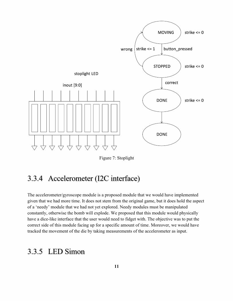
11
Figure 7: Stoplight
3.3.4 Accelerometer (I2C interface)
The accelerometer/gyroscope module is a proposed module that we would have implemented given that we had more time. It does not stem from the original game, but it does hold the aspect of a ‘needy’ module that we had not yet explored. Needy modules must be manipulated constantly, otherwise the bomb will explode. We proposed that this module would physically have a dice-like interface that the user would need to fidget with. The objective was to put the correct side of this module facing up for a specific amount of time. Moreover, we would have tracked the movement of the die by taking measurements of the accelerometer as input.
3.3.5 LED Simon

12
The LED Simon module is another proposed module that we would have implemented given more time. It stems from the original game and the idea originates from Simon Say’s. The module would have had four buttons that would light up in a specific order. To pass the module, the user would need to play the sequence in the same order that had been given.
3.3.6 Cut wires
This wire cutting module is one of the modules we really wanted to implement in our project. It also takes after a similar module in the original game, but bringing the module to the physical realm would have brought our project to another level of bomb defusing realism. The physical interface would have presented the user with a variety of wires (of various colors) on a breadboard. To defuse it, one would need to physically cut or detach wires in a specific order.
3.4 Strikes Module
The strikes module is a finite state machine that takes as input a signal called ‘strike’ sent by the bomb logic block, and outputs the signals might be ‘warning_lights’ and ‘explode’. The strike state machine has a default state of ZERO, and upon each assertion of ‘strike’, will change states and update ‘warning_lights’/’explode’ accordingly. The ‘warning_lights’ signal will be sent to the labkit to track the number of strikes they have accumulated. It will also be used to update the bomb image on the computer monitor. The ‘explode’ output signal will be sent to the explode module.

13
Figure 9: Strikes Module
3.5 Explode Module
The explode module operates on the clock at 65mhz and takes as input a signal called ‘explode’, which will be asserted by either the ‘strikes module' or ‘countdown timer module’. The explode module will output a ‘game_over’ signal that will be sent to the ‘bomb logic block’.

14
Figure 10: Explode module
3.6 RNG Block
We proposed that this RNG block would help provide an aspect of randomness to our game. It would be in charge of selecting the modules that would be active on the bomb as well as the specific version of the modules. Our early concepts of this module was for it to take the last 3 bits of a floating analog sensor for a pseudo random generation. Another idea was for it to take the last few bits of a timer that begins counting from the most recent reset, which would be random enough given that the user can begin the game whenever he wants.
4. Testing

15
Because the project was inherently modular, it was fairly simple to test each aspect of our game. Nearly every aspect could be independently tested, such as the image display, individual bomb modules, strike and explode modules, and the bomb logic. Because of this, putting all of these modules together was a relatively simple task.
5. TimelineCommitment
Functional game system with three working game moduleso Bait and Switch – Flip the FPGA switches to the correct alignmentso Stop Me! – Stop the LED bar graph’s light at the right sloto Don’t Press the Big Red Button – Press and release the button on time
Recognize the numbers on the timer to verify when button was released Robust peripherals for manipulation of associated bomb modules Corresponding graphics displayed on the computer monitor in accordance to the bomb
o Loading images from BRAM onto the screeno Flexible, modular numbering schemeo Flexible, re-positionable game images/graphics
Basic game logic/bomb logic (minimum viable product of game)
Goal All of the above Accelerator bomb module – Rotate this peripheral every so often Non-deterministic module variables
o Different versions of each module (different version = different solution)o Variables randomly chosen during generation of the bomb
Use compact flash to store all the different module images
Stretch Goal All of the above Simon Says bomb module – Press led buttons in accordance to the pattern Sound to simulate a bomb explosion/defused indication Wire you so difficult bomb module – Disconnect/connect appropriate wires Randomized placement of modules on the displayed bomb and further randomizing game
Task 11/11 11/18 11/25 12/2 12/9
Game FSM/Bomb Logic

16
Expert Manual
Game Elements (strike, explode, RNG)
Displaying on Monitor, SD interface
Bomb Modules
Bomb Module Peripherals
Testing/Debugging
Stretch goals: speakers, randomness
Presentation, Checkoff, Final Report
Figure 11: Blue-Mitchell, Red-Amelia, Purple-Both
6. ResourcesFor our game we will be using the labkit and the monitor. Each module will include input from peripherals, based on what sorts of interfaces we can get. Examples include an LED Button Pad, a large button, a keypad, some standard LEDs, and a segmented LED bar graph. We are also thinking of using a keyboard, an accelerometer, and a wired breadboard interface.
7. Conclusion

17
This bomb defusal game allows the user to view a bomb puzzle on the screen and use inputs on the labkit to manipulate the bomb. This is a two player game as the user manipulating the labkit inputs will not have the instructions to defuse it, so it is also about teamwork and effective communication. The game will have the visual of the bomb on the screen and a countdown timer for the players on the LEDs. Each module in the bomb will be controlled with its own inputs and have wires to the main game FSM for its completion. This project will connect interaction and processing of peripherals to the labkit as well as a game state machine element and a vga display output.