FPGA-Based Rapid Prototyping of Digital Signal Processing ...
30
RESEARCH CENTRE FOR INTEGRATED MICROSYSTEMS – UNIVERSITY OF WINDSOR FPGA-Based Rapid Prototyping of Digital Signal Processing Systems Kevin Banovic, Mohammed A. S. Khalid, and Esam Abdel-Raheem Presented By Kevin Banovic July 29, 2005 To be presented at the 48 th Midwest Symposium on Circuits and Systems, Cincinnati, Ohio, August 7-10, 2005
Transcript of FPGA-Based Rapid Prototyping of Digital Signal Processing ...

RESEARCH CENTRE FOR INTEGRATED MICROSYSTEMS – UNIVERSITY OF WINDSOR
FPGA-Based Rapid Prototyping of Digital Signal Processing Systems
Kevin Banovic, Mohammed A. S. Khalid, andEsam Abdel-Raheem
Presented By Kevin Banovic
July 29, 2005
To be presented at the 48th Midwest Symposium on Circuits and Systems, Cincinnati, Ohio, August 7-10, 2005

RESEARCH CENTRE FOR INTEGRATED MICROSYSTEMS – UNIVERSITY OF WINDSOR
OBJECTIVEOBJECTIVE
To provide a current survey of design methodologies To provide a current survey of design methodologies and CAD tools for FPGA-based rapid prototyping of and CAD tools for FPGA-based rapid prototyping of DSP systems.DSP systems.

KEVIN BANOVIC Slide 3
RESEARCH CENTRE FOR INTEGRATED MICROSYSTEMS – UNIVERSITY OF WINDSOR
RCIM SEMINAR
Outline
1. Introduction
2. Standard RTL Design
3. System-Level Design
4. Hardware/Software Co-design
5. Emulation and Prototyping
6. Conclusions
7. References

KEVIN BANOVIC Slide 4
RESEARCH CENTRE FOR INTEGRATED MICROSYSTEMS – UNIVERSITY OF WINDSOR
RCIM SEMINAR
Introduction
Traditionally, DSP algorithms have been implemented with either ASICs or PDSPs
However, an FPGA implementation can offer a compromise between the performance of fixed-functionality hardware and the flexibility of re-programmable devices
As opposed to PDSPs, FPGAs allow non-standard word-length sizes and semi- or full-parallel signal processing, which can reduce area and/or improve throughput
FPGA-based emulation platforms offer real-time prototyping of ASIC logic, which allows system verification and optimization in an environment that resembles the target system

KEVIN BANOVIC Slide 5
RESEARCH CENTRE FOR INTEGRATED MICROSYSTEMS – UNIVERSITY OF WINDSOR
RCIM SEMINAR
Outline
1. Introduction
2. Standard RTL Design
3. System-Level Design
4. Hardware/Software Co-design
5. Emulation and Prototyping
6. Conclusions
7. References

KEVIN BANOVIC Slide 6
RESEARCH CENTRE FOR INTEGRATED MICROSYSTEMS – UNIVERSITY OF WINDSOR
RCIM SEMINAR
Standard RTL Design
• The standard top-down RTL design flow requires two distinct sets of design tools; (1) algorithmic development & analysis and (2) hardware synthesis/implementation
• This creates a gap within the design flow, which prevents it from being a true top-down design methodology
• Algorithmic design and analysis is typically done at a high level of abstraction in a floating-point environment
Har
dw
are
Syn
thes
is

KEVIN BANOVIC Slide 7
RESEARCH CENTRE FOR INTEGRATED MICROSYSTEMS – UNIVERSITY OF WINDSOR
RCIM SEMINAR
Standard RTL Design
The resulting floating-point model is converted into a fixed-point model, and simulations are done to verify equivalence
An RTL description of the fixed-point model is generated and the design is simulated to confirm functionally
RTL design refers to the methodology of modeling a sequential circuit or system as a set of registers and a set of transfer functions which describe the flow of data between registers
Logic synthesis is performed to create an optimized gate-level netlist, which is based on design constraints such as timing
Synthesis constraints directly affect the effort required for placement and routing, and if the design is over-constrained, routing failure may occur since resources are fixed in FPGAs

KEVIN BANOVIC Slide 8
RESEARCH CENTRE FOR INTEGRATED MICROSYSTEMS – UNIVERSITY OF WINDSOR
RCIM SEMINAR
Standard RTL Design
Physical synthesis partitions the incoming netlist into available logic resources and is typically carried out with FPGA vendor place and route tools
Equivalence checking is performed after both logic and physical synthesis to verify design functionality
In the final step, a bit file is generated to program the FPGA
Complete design environments are offered by Altera (Quartus II), Xilinx (ISE), and Mentor Graphics (FPGA Advantage), which integrate with a number of third party EDA tools
To reduce development times, DSP design has gravitated towards the use of IP cores and customizable designware for common DSP functions

KEVIN BANOVIC Slide 9
RESEARCH CENTRE FOR INTEGRATED MICROSYSTEMS – UNIVERSITY OF WINDSOR
RCIM SEMINAR
Outline
1. Introduction
2. Standard RTL Design
3. System-Level Design
4. Hardware/Software Co-design
5. Emulation and Prototyping
6. Conclusions
7. References

KEVIN BANOVIC Slide 10
RESEARCH CENTRE FOR INTEGRATED MICROSYSTEMS – UNIVERSITY OF WINDSOR
RCIM SEMINAR
System-Level Design
Most DSP designers work at the algorithmic level and use C/C++ or Matlab for verification and architectural exploration
While this reduces time for system development, it has created a gap within the standard RTL design flow
Translation between floating- and fixed-point models is a manual error-prone process that makes it difficult to make changes at the algorithmic level
This has led to the development of several system-level design tools, which automate the conversion of high level languages and RTL to create a true top-down design methodology
Algorithmic synthesis solutions provide tools for auto-quantization, architectural definition, RTL model generation (including testbeches), and area/timing optimization
KEVIN BANOVIC Slide 11
RESEARCH CENTRE FOR INTEGRATED MICROSYSTEMS – UNIVERSITY OF WINDSOR
RCIM SEMINAR
System-Level Design
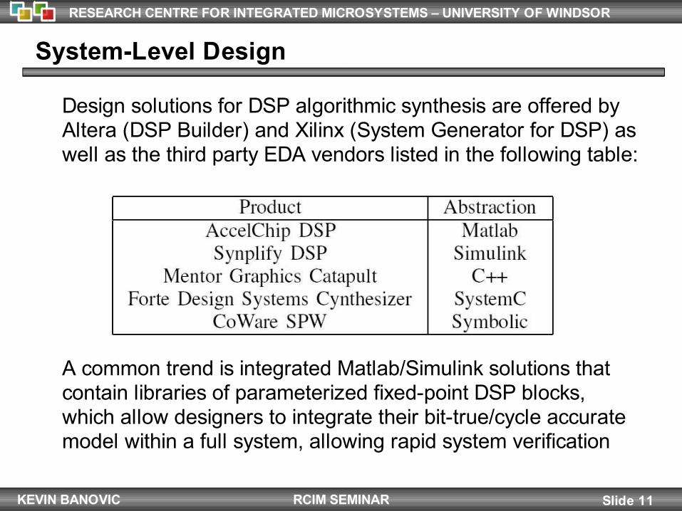
Design solutions for DSP algorithmic synthesis are offered by Altera (DSP Builder) and Xilinx (System Generator for DSP) as well as the third party EDA vendors listed in the following table:
A common trend is integrated Matlab/Simulink solutions that contain libraries of parameterized fixed-point DSP blocks, which allow designers to integrate their bit-true/cycle accurate model within a full system, allowing rapid system verification

KEVIN BANOVIC Slide 12
RESEARCH CENTRE FOR INTEGRATED MICROSYSTEMS – UNIVERSITY OF WINDSOR
RCIM SEMINAR
Outline
1. Introduction
2. Standard RTL Design
3. System-Level Design
4. Hardware/Software Co-design
5. Emulation and Prototyping
6. Conclusions
7. References

KEVIN BANOVIC Slide 13
RESEARCH CENTRE FOR INTEGRATED MICROSYSTEMS – UNIVERSITY OF WINDSOR
RCIM SEMINAR
Hardware/Software (HW/SW) Co-Design
• HW/SW co-design refers to the methodology, tools, and practices that support the design of embedded systems and SoC
• An embedded system consists of one or more processors and ASICs connected to a common bus
• This creates an environment with both multi-processing and multiprogramming capabilities

KEVIN BANOVIC Slide 14
RESEARCH CENTRE FOR INTEGRATED MICROSYSTEMS – UNIVERSITY OF WINDSOR
RCIM SEMINAR
Hardware/Software Co-Design
In modern HW/SW co-design, languages such as C/C++ have been used to represent both hardware and software, which allows partitioning to occur at a later stage in the design flow, increasing the interaction/feedback between partitions
The HW/SW co-design flow begins with algorithmic design & analysis, which is followed by hardware/software partitioning
Components that can be accelerated in hardware such as sensor applications are assigned to hardware partitions, while components better suited to software such as complex algorithms are assigned to software partitions
RTL and C/C++ models are generated for the hardware and software components, respectively, by manual or automatic methods
KEVIN BANOVIC Slide 15
RESEARCH CENTRE FOR INTEGRATED MICROSYSTEMS – UNIVERSITY OF WINDSOR
RCIM SEMINAR
Hardware/Software Co-Design
HW/SW co-simulation follows which links an RTL simulator for hardware with an instruction-set simulator (ISS) for software
An interface between the simulators is necessary and typically consists of a bus wrapper and interprocess communication (IPC)
The bus wrapper synchronizes the ISS with the system simulation and translates the incoming data from the ISS into cycle-accurate bus transactions
IPC primitives are used to communicate with the distinct processes run by the ISS on the host system
Once an architecture has been chosen based on co-simulation results, the synthesis of hardware components follows that of the standard RTL design process from logic synthesis onwards
KEVIN BANOVIC Slide 16
RESEARCH CENTRE FOR INTEGRATED MICROSYSTEMS – UNIVERSITY OF WINDSOR
RCIM SEMINAR
Hardware/Software Co-Design
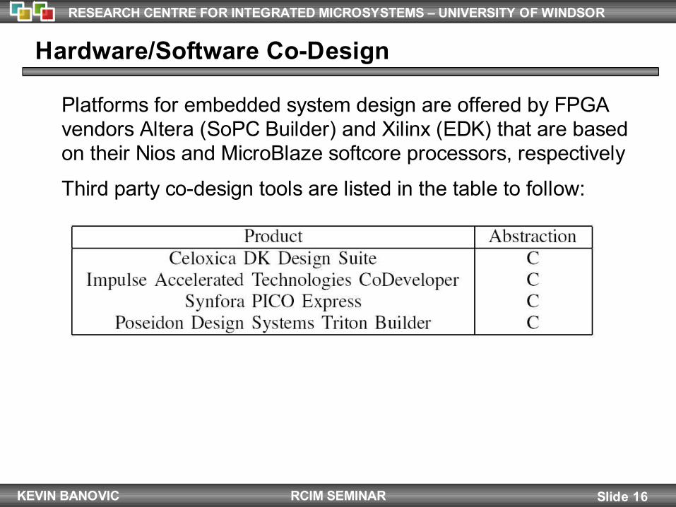
Platforms for embedded system design are offered by FPGA vendors Altera (SoPC Builder) and Xilinx (EDK) that are based on their Nios and MicroBlaze softcore processors, respectively
Third party co-design tools are listed in the table to follow:

KEVIN BANOVIC Slide 17
RESEARCH CENTRE FOR INTEGRATED MICROSYSTEMS – UNIVERSITY OF WINDSOR
RCIM SEMINAR
Outline
1. Introduction
2. Standard RTL Design
3. System-Level Design
4. Hardware/Software Co-design
5. Emulation and Prototyping
6. Conclusions
7. References

KEVIN BANOVIC Slide 18
RESEARCH CENTRE FOR INTEGRATED MICROSYSTEMS – UNIVERSITY OF WINDSOR
RCIM SEMINAR
Emulation and Prototyping
Hardware emulation is an alternate approach to system verification, which reduces simulation time while retaining high confidence results
A hardware emulator is a reconfigurable computer that can be programmed to emulate a large digital design
Rapid prototyping in the accelerated development of a physical system for demonstration, evaluation, testing, or verification
The prototyping of ASIC circuits as well as the development and verification of new IP cores are applications that are well suited to FPGA-based emulation

KEVIN BANOVIC Slide 19
RESEARCH CENTRE FOR INTEGRATED MICROSYSTEMS – UNIVERSITY OF WINDSOR
RCIM SEMINAR
Emulation and Prototyping
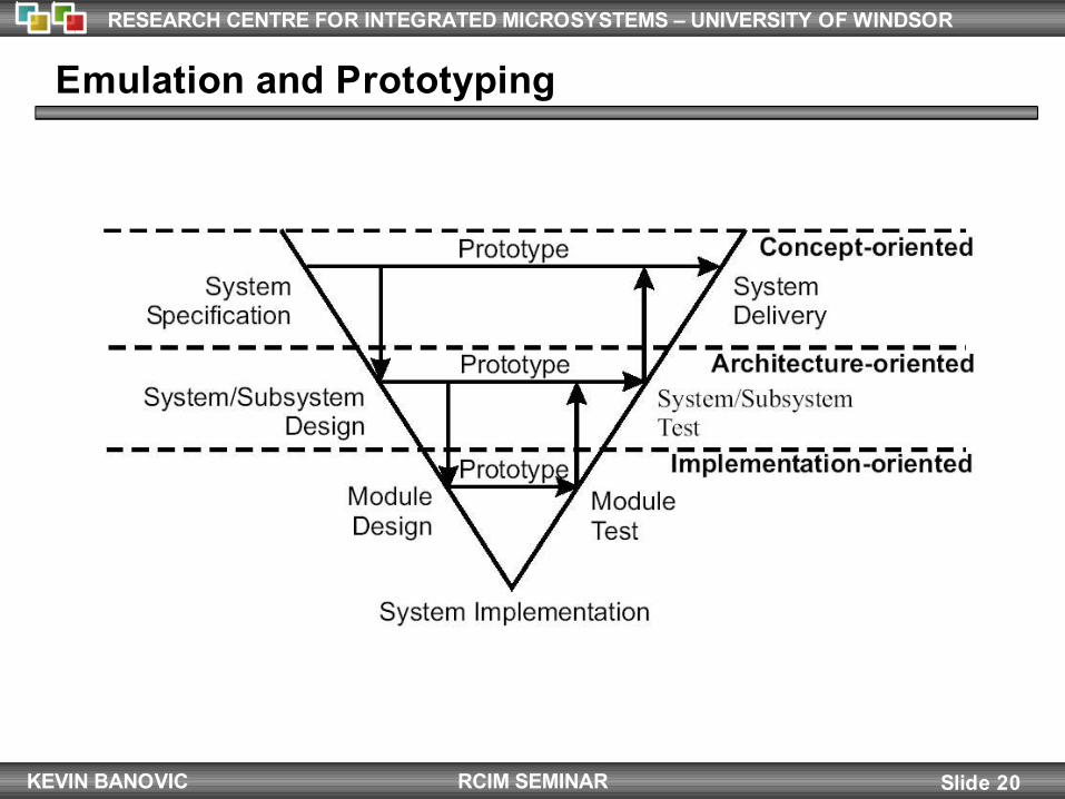
There are three main classes of prototyping systems:Concept-oriented: explores the design requirements and specifications of the systemArchitecture-oriented: consists of system-level design, testing, and verification, as well as subsystem specification (supports HW/SW partitioning and co-simulation)Implementation-oriented: consists of module design and RTL or gate-level testing or verification
As illustrated in the figure to follow, the three classes of prototyping interact with each other and follow a natural progression to system implementation
KEVIN BANOVIC Slide 20
RESEARCH CENTRE FOR INTEGRATED MICROSYSTEMS – UNIVERSITY OF WINDSOR
RCIM SEMINAR
Emulation and Prototyping

KEVIN BANOVIC Slide 21
RESEARCH CENTRE FOR INTEGRATED MICROSYSTEMS – UNIVERSITY OF WINDSOR
RCIM SEMINAR
Emulation and Prototyping
FPGA-based emulation systems have been the dominant platform for ASIC prototyping for many years
With current FPGA capacities exceeding six million gates (Xilinx Virtex-4), it is possible to emulate large SoC designs on a single FPGA
Synopsys offers an ASIC prototyping solution called DC FPGA, which eliminates the need for manual conversion between ASIC and FPGA designs, allowing a single RTL design to be developed for both prototyping and implementation
Several multi-FPGA emulation systems have been developed with the capacity to emulate large ASIC designs; mainly VStation Pro from Mentor Graphics and the Berkeley Emulation Engine (BEE)

KEVIN BANOVIC Slide 22
RESEARCH CENTRE FOR INTEGRATED MICROSYSTEMS – UNIVERSITY OF WINDSOR
RCIM SEMINAR
Emulation and Prototyping
These systems consist of on upwards of several hundred FPGAs distributed across multiple PCBs
Inter-FPGA routing is accomplished by several routing architectures, which include the partial-crossbar (PXB) and the hybrid complete-graph partial-crossbar (HCGP)
Multi-FPGA systems have high place and route times, and partitioning is restricted by pin count, which reduces the FPGA logic utilization
Additionally, routing delays reduce the maximum frequency to a fraction of that of a single FPGA
KEVIN BANOVIC Slide 23
RESEARCH CENTRE FOR INTEGRATED MICROSYSTEMS – UNIVERSITY OF WINDSOR
RCIM SEMINAR
Emulation and Prototyping
Recently, there has been a recent shift towards processor-based emulation (PBE) systems such as Cadence’ Palladium 2
These emulators consist of highly parallel processors that are used to emulate ASIC logic

KEVIN BANOVIC Slide 24
RESEARCH CENTRE FOR INTEGRATED MICROSYSTEMS – UNIVERSITY OF WINDSOR
RCIM SEMINAR
Outline
1. Introduction
2. Standard RTL Design
3. System-Level Design
4. Hardware/Software Co-design
5. Emulation and Prototyping
6. Conclusions
7. References

KEVIN BANOVIC Slide 25
RESEARCH CENTRE FOR INTEGRATED MICROSYSTEMS – UNIVERSITY OF WINDSOR
RCIM SEMINAR
Conclusions
The focus of the FPGA community has been divided into two main groups: signal processing and embedded system design
In the area of signal processing, FPGAs will continue to be a dominant platform for front end sensor applications
The number of embedded multipliers and processors on FPGAs will increase, enabling FPGAs to better compete against PDSPs
As the gap between system-level and RTL design decreases, system-level design methodologies will become the convention
This shift has already begun with the plethora of system-level design tools available and the use of IP cores and designware

KEVIN BANOVIC Slide 26
RESEARCH CENTRE FOR INTEGRATED MICROSYSTEMS – UNIVERSITY OF WINDSOR
RCIM SEMINAR
Conclusions
In the area of embedded system design, less application-specific design tools and methodologies which are able to obtain efficient HW/SW partitions are essential for co-design methodologies to obtain widespread acceptance
A critical step is the development of sophisticated profiling tools that can efficiently partition designs into HW/SW based on execution performance
Lastly, FPGA-based emulation systems are expected to continue to rival PBE-based emulation systems as the dominant platform for the rapid prototyping of ASIC logic
KEVIN BANOVIC Slide 27
RESEARCH CENTRE FOR INTEGRATED MICROSYSTEMS – UNIVERSITY OF WINDSOR
RCIM SEMINAR
Thank You! Questions or Comments?

KEVIN BANOVIC Slide 28
RESEARCH CENTRE FOR INTEGRATED MICROSYSTEMS – UNIVERSITY OF WINDSOR
RCIM SEMINAR
References

KEVIN BANOVIC Slide 29
RESEARCH CENTRE FOR INTEGRATED MICROSYSTEMS – UNIVERSITY OF WINDSOR
RCIM SEMINAR
References

KEVIN BANOVIC Slide 30
RESEARCH CENTRE FOR INTEGRATED MICROSYSTEMS – UNIVERSITY OF WINDSOR
RCIM SEMINAR
References