Amenability of Multigrid Computations to FPGA-Based Acceleration*
General rights Copyright and moral rights for the publications made accessible in the public portal are retained by the authors and/or other copyright owners and it is a condition of accessing publications that users recognise and abide by the legal requirements associated with these rights.
• Users may download and print one copy of any publication from the public portal for the purpose of private study or research. • You may not further distribute the material or use it for any profit-making activity or commercial gain • You may freely distribute the URL identifying the publication in the public portal
If you believe that this document breaches copyright please contact us providing details, and we will remove access to the work immediately and investigate your claim.
Downloaded from orbit.dtu.dk on: Jul 22, 2018
FPGA Acceleration by Dynamically-Loaded Hardware Libraries
Lomuscio, Andrea ; Nannarelli, Alberto; Re, Marco
Publication date:2016
Document VersionPublisher's PDF, also known as Version of record
Link back to DTU Orbit
Citation (APA):Lomuscio, A., Nannarelli, A., & Re, M. (2016). FPGA Acceleration by Dynamically-Loaded Hardware Libraries.Kgs. Lyngby: Technical University of Denmark (DTU). (DTU Compute-Technical Report-2016; No. 3).
FPGA Acceleration by
Dynamically-Loaded Hardware Libraries
DTU Compute Technical Report-2016-03
Andrea Lomuscio, Alberto Nannarelli(1) and Marco Re(2)
(1) DTU Compute, Technical University, Kongens Lyngby, Denmark(2) Dept. Electronics, University of Rome “Tor Vergata”, Rome, Italy
Abstract
Hardware acceleration is a viable solution to obtain energy efficiency in data intensivecomputation.
In this work, we present a hardware framework to dynamically load hardware libraries,HLL, on reconfigurable platforms (FPGAs). Provided a library of application-specificprocessors, we load on-the-fly the specific processor in the FPGA, and we transfer theexecution from the CPU to the FPGA-based accelerator.
Results show that significant speed-up and energy efficiency can be obtained by HLLacceleration on system-on-chips where reconfigurable fabric is placed next to the CPUs.
1 Introduction
Excessive power dissipation is probably the main concern in setting up and operating largecomputer installations, such as data centers or server rooms.
In these computer clusters, power is dissipated not only in the computation, but also in keepingthe machines cool: fans for heat removal and room air conditioning. Clearly, a large energyconsumption has an impact on the electricity cost and on the environment.
Accelerators are special processors designed to perform computation for a specific set of appli-cations efficiently in time (the name derives from this) and energy consumption.
Most computers are today equipped with accelerators to off-load the main processors, CPUsor cores in the following, to get more data processed per hour (i.e., throughput) and to saveenergy [1–3].
There are two main categories of accelerators:
General purpose accelerators, such as Graphic Processing Units (GPUs), which are able toprocess in high parallelism standard arithmetic operations (addition, multiplication, etc.).
Application Specific Processors implemented on reconfigurable hardware platforms (e.g., FP-GAs) which are tailored to efficiently execute a specific application.
The main advantages of FPGA-based reconfigurable accelerators are that they can implementvirtually any circuit, and that they can be reconfigured at run-time by making the systemadaptable to the specific workload.
The disadvantage is that these FPGA-based Application-Specific Processors (ASPs) have tobe designed, implemented, and tested. This results in much longer development time than thesoftware solution where the application is run on CPUs or GPUs [4].
To reduce the development time, the ASP implementation must be done in a systematic andmodular way, by using tools, such as FloPoCo [5] or Vivado HLS [6], and by developing newad-hoc tools.
Our target is to have these reconfigurable hardware accelerators next to the cores to execute thecomputing workload fast and energy efficiently, with the objective of increasing power efficiency.
In the specific case of FPGA-based accelerators, the main problem is the configuration latency,that is, the time it takes to load the configuration of the ASP in the FPGA. If this configurationlatency cannot be reduced to a minimum, the overall performance will be affected.
Our idea is to use a concept similar to the working-set (WS) used in virtual memory to identifythe data resident in main memory.
We identify a number of applications worthwhile acceleration (frequently used and with goodspeed-up/energy returns). We call this set a pool (of applications). If outside the pool, theapplication is run in the CPU. In contrast, if the application is in the pool, we develop acorresponding ASP. The configurations (FPGA programming files) of these ASPs constitutethe ASP library and are stored in memory.
Depending on the computer workload, a run-time manager, implemented as a part of theoperating system, selects the applications to be in the WS and load the corresponding ASPsin the FPGA.
To address these issues, we present an architecture for the reconfigurable part of a System-on-Chip (SoC) comprising CPU cores and FPGA fabric. The acceleration is obtained by bothefficient ASPs and increased parallelism: several ASPs working in parallel. When possible, thereconfiguration of the FPGA is done partially and on-the-fly: while one part of the FPGA isconfigured, other parts are executing computations.
As examples to demonstrate the computing platform (architecture), we developed a set ofASPs to accelerate in hardware specific applications. The domain of application is large serversclusters, such as the ones in data centers. We leave the implementation of the run-time managerfor future work.
As implementation platform, we opted for the Xilinx Zynq SoC because it is well supportedby CAD tools [6] and relatively inexpensive. Although the Zynq SoC is intended for use inembedded systems and not for high performance computing, the proposed architecture can bealso ported to different SoCs (e.g., [7]) provided a minimum set of features, such as partialdynamic reconfiguration, are supported.
Results show that for the selected pool a speed-up in the range 10–100 times and an energyefficiency up to 30 times can be achieved by using the proposed technology.
2
2 HLL Architecture
In this section, we present the architecture designed to implement the dynamically-loadedhardware libraries (HLL), after a brief introduction of the used platform and a list of modes toconfigure the FPGA.
2.1 Implementation Platform
The platform used for implementing the accelerators is the Z-7020 device of the Xilinx ZynqTM-7000 SoC family. The architecture of the ZynqTM comprises two different parts: the ProcessingSystem (PS), the CPUs, and the Programmable Logic (PL), the FPGA. These two sections areindependent (they also have distinct power domains) and can be used separately or in conjunc-tion. The interconnection between the PS, PL and the software-configurable I/O peripheralsis provided by the AMBA AXI bus.
The Processing System (PS) of the device features a dual-core ARM Cortex-A9 with a 32-bitRISC architecture [8]. Next to the processors are the two NEON Media Processing Engines forSIMD operations, the 32KB L1 and 512KB L2 caches and the 256KB on-chip-memory RAM.A multi-protocol DDR memory controller is provided to support external DRAM memories.
The other main portion of the Zynq-7000 SoC is the Programmable Logic (PL). This generalpurpose 28nm FPGA fabric is based on the Xilinx Artix-7 technology. The key features,other than the Configurable Logic Blocks (CLBs), are the dual-ported 36Kb Block RAMs(dedicated memory resources) and the DSP48E slices (dedicated blocks for high-speed integermultiplication and addition).
The communication between PC and PL can be implemented either by the AXI4-Lite or bythe AXI4-Stream protocols.
The AXI4-Lite is a simplified version of the AXI4 protocol and allows simple write and readfunctions on memory-mapped registers implemented in the PL. Its main advantage is the easeof use at expenses of a lower transfer rate.
The AXI4-Stream is the protocol used to transfer large data sets; e.g., via direct memory access(DMA). It allows to send data burst lengths up to 256 beats1. Moreover, the bus width can beincreased up to 1024 bits, while the AXI4-Lite data width is fixed to 32 bits.
2.2 FPGA Programming Modes
The PL part can be programmed, or configured, statically by loading the bitstream in theconfiguration memory before starting using the FPGA, or dynamically (partial reconfiguration)by loading bitstreams only to subsets of the configuration memory corresponding to selectedareas of the FPGA.
2.2.1 Static Configuration
The static configuration allows the maximum flexibility in terms of architecture of the ASPimplemented. Moreover, the size of the ASP can stretch to the maximum usable area of the
1A “beat” is an individual data transfer within an AXI burst (e.g., one 4-byte word for 32-bit bus width).
3
PL.
The configuration of the FPGA is done by the Processor Configuration Access Port (PCAP).The PCAP interface can send and receive 32-bit words at 100 MHz rate, resulting in a maximumtheoretical bitstream transfer speed of 400 MB/s for plain PL configuration. However, due todifferent overheads, the maximum transfer rate measured in our experiments was about 128MB/s.
The drawback of the static configuration is that the bitstream loading time, called configurationlatency in the following, can be quite long, depending on the size of the ASP and the compressionfactor of the bitstream. We measured configuration latencies in the range 10–20 ms, for ourdesigns. Another drawback is that no parts of the PL can be used until the configuration iscompleted.
Therefore, hiding the configuration latency can be very tricky. If we use only a CPU, we canuse one of the following strategies:
1. Start configuring the PL and poll the PCAP until the configuration is completed. In thiscase, no configuration latency is hidden.
2. Start configuring the PL for application A, then return to executing some other programB on the CPU, and execute the accelerated application A on the PL after a time thatguarantees the configuration is completed for the worst case scenario (maximum config-uration latency). In this case, the configuration latency is hidden, but we must ensurethat the execution latency of program B is longer than the configuration latency, and,this can be tricky if the execution latency of B is determined at run-time.
2.2.2 Dynamic Partial Configuration
The dynamic partial configuration, can be done on-the-fly on one portion of the PL, whileASPs, configured on other parts of the PL, keep running. The configuration latency is reducedbecause the bitstreams are smaller: less FPGA area to configure than the static case.
The dynamic configuration of the selected area is done by the Internal Configuration AccessPort (ICAP), a hardware block that can read and write the FPGA configuration memory.
The ICAP allows to configure the FPGA directly from the PL. For this reason, full bitstreams(static configurations) cannot be loaded by the ICAP because the ICAP itself is part of thePL. As the PCAP, also the ICAP can reach a transfer rate of 400 MB/s, but since the ICAPcontroller provided by Xilinx (AXI HWICAP) has only an AXI4-Lite interface, the transferrate is reduced to just 19 MB/s.
However, as proposed in [9], we connect an AXI4-Stream interface to the ICAP and transferthe bitstream via DMA. In this way, we obtain a transfer rate close to the theoretical limit of400MB/s.
Since the ICAP is faster than the PCAP (400 MB/s vs. 128 MB/s) and the bitstreams aresmaller, the configuration latency is quite small (0.5–1 ms) compared to the static configuration.Therefore, hiding the configuration latency for dynamic partial configuration is doable, becausethe latency is short and other parts of the PL can execute other applications.
By using the concept of working-set (WS), we can configure a new ASP by partial configurationwhile, running other applications.
4
It is crucial not to load ASPs that will be used for short time since this can result in “thrashing”:a) the overhead of the configuration latency may offset the benefit of acceleration because ofthe short utilization of the ASP; b) the loaded ASP will evict from the WS (FPGA) anotherASP more frequently used that will need to be reloaded soon. The result is performance loss.
However, a drawback of dynamic reconfiguration is that a smaller area is available to implementthe ASPs because part of the PL is used for the interface with the PS and for the ICAP.
Another drawback is that the flexibility is reduced, because fixed (static) interfaces are requiredto accommodate different ASPs in the reserved area and ensure the correct communication tothe PS.
To address this latter problem, we design a general framework for the partial reconfigurationof ASPs in the PL, and identify a number of FPGA layouts suitable to accommodate ASPs ofdifferent sizes and timing requirements (operating clock frequencies).
2.3 Accelerator Architecture
The architecture of the acceleration fabric on the PL is designed taking into account severalaspects, including:
• dynamic reconfiguration of reserved areas;
• clock rate adaptable to the specific ASP timing constraint;
• amount of data transferred from/to memory.
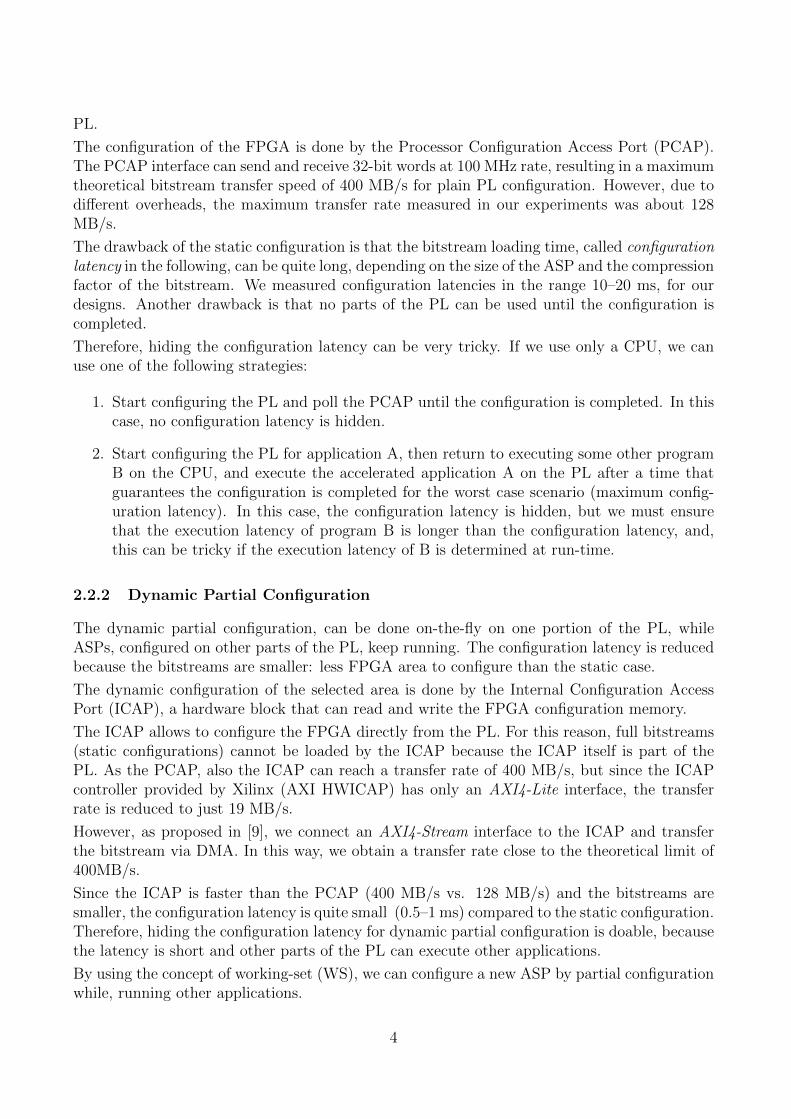
The interface toward the PS side is through four high-performance ports (HP 0-3) which connectthe PL to the ARM CPUs and the DRAM controller, and through the AXI ACP port whichconnects directly to the cache. In addition, the interface PS-PL provides four programmableclocks.
Fig. 1 shows the architecture of the accelerator with four reconfigurable portions (RP 1–4). Inthe figure we identify the “static part” and the “dynamic part”.
The static part is loaded statically by the PCAP and does not change on-the-fly. It consists offive AXI4-Stream blocks, the ICAP, and a clock management unit.
Since port ACP is not connected to the DRAM controller, the ASP connected to this port,cannot transfer large chunks of data. The maximum size is set by the cache size (512 Kbytes).
Each of the reconfigurable areas can be connected to the PS through the 32-bit AXI GP portsusing the AXI4-Lite bus.
Interrupts are used to signal change of status (end of configuration, data ready, etc.) in the RPareas to the PS.
Each of the four RPs in the dynamic part is dynamically reconfigured by the ICAP. If theASP does not fit the RP, we can resize the configurable block eliminating one or more of theRPs by static reconfiguration via PCAP. Although “Grid-style” block placement allows moreflexibility, we were forced to use “Island-style” block placement because it is the only stylecurrently supported by Vivado.
The shortcomings of “Island-style” are internal fragmentation, i.e., part of the reserved area inthe RP may not be used, and fixed interface to the static part of the PL.
5
HP 0
ACP
HP 1
HP 2
HP 3
ICAP
RP 1
PL - Static PartPS
AXI-Stream 64-Bits AXI-Lite 32-Bits
GP 0
IRQ
Interrupts
DMA Controller
PL - Dynamic Part
RP 4
DMA Controller
DMA Controller
DMA Controller
DMA Controller
RP 2
RP 3
ClockManagerCLK 1 - 5
Figure 1: HLL hardware architecture (not in scale).
AXI-Lite Bus AXI-Stream Master Bus
AXI-Stream Slave Bus Interrupt
CLK
RST IP A
STATIC PARTITION
RECONFIGURABLE PARTITION
WRAPPER
CLK
RST
Interrupt
S_00
S_01
M_00
AXI-Lite Bus
Interrupt
CLK
RST IP C
STATIC PARTITION
RECONFIGURABLE PARTITION
WRAPPER
CLK
RST
Interrupt
S_00
S_01
M_00
Figure 2: IP-Wrapper interface for two different blocks.
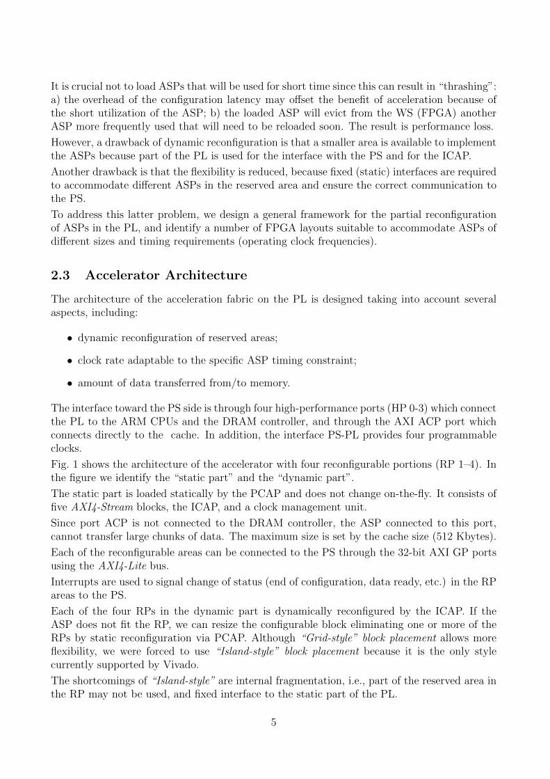
To overcome the latter limitation, we introduce an ASP wrapper, “IP-Wrapper”, to adapt thespecific ASP interface to a standard one built to accommodate the most demanding interface ofthe ASPs in the pool. Fig. 2 shows how the IP-Wrapper is used to interface two IP-blocks withdifferent connection ports. The interface ports (red boxes) can be either connected to actualIP-block’s ports, or to dummy buffers (green triangles) if the interface port is not used by theIP-block (Fig. 2, at right).
By IP-Wrappers, we can easily connect pre-existing soft IP-blocks without modifying them,and save ASP development time.
Moreover, each RP can be clocked at a specific frequency thanks to the “Clock Manager”(Fig. 1), allowing maximum flexibility and IP-block reuse.
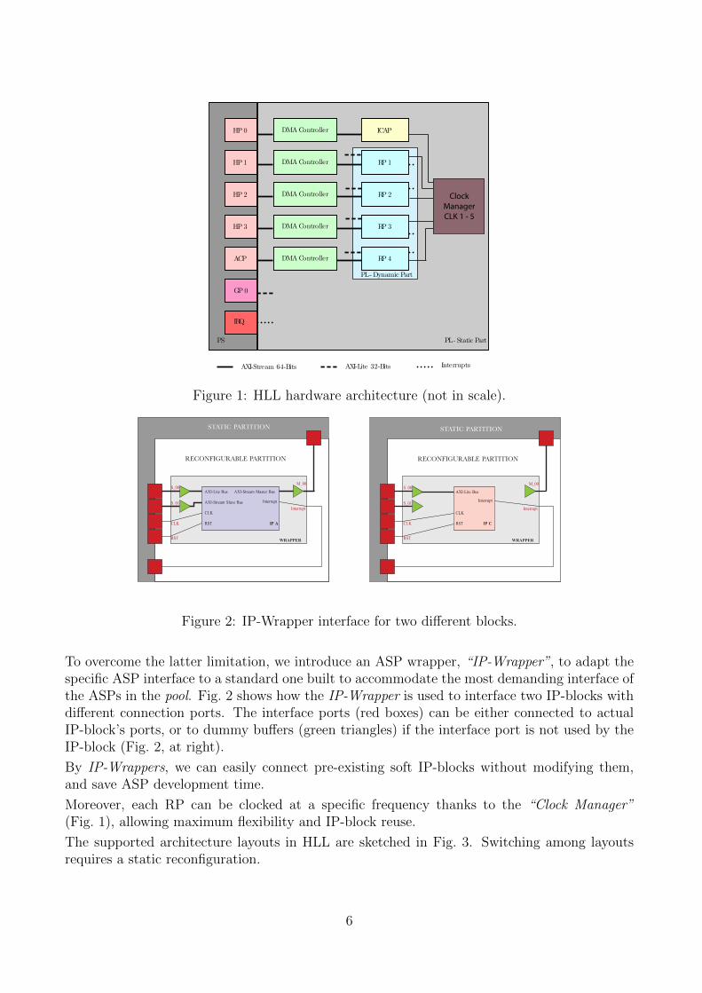
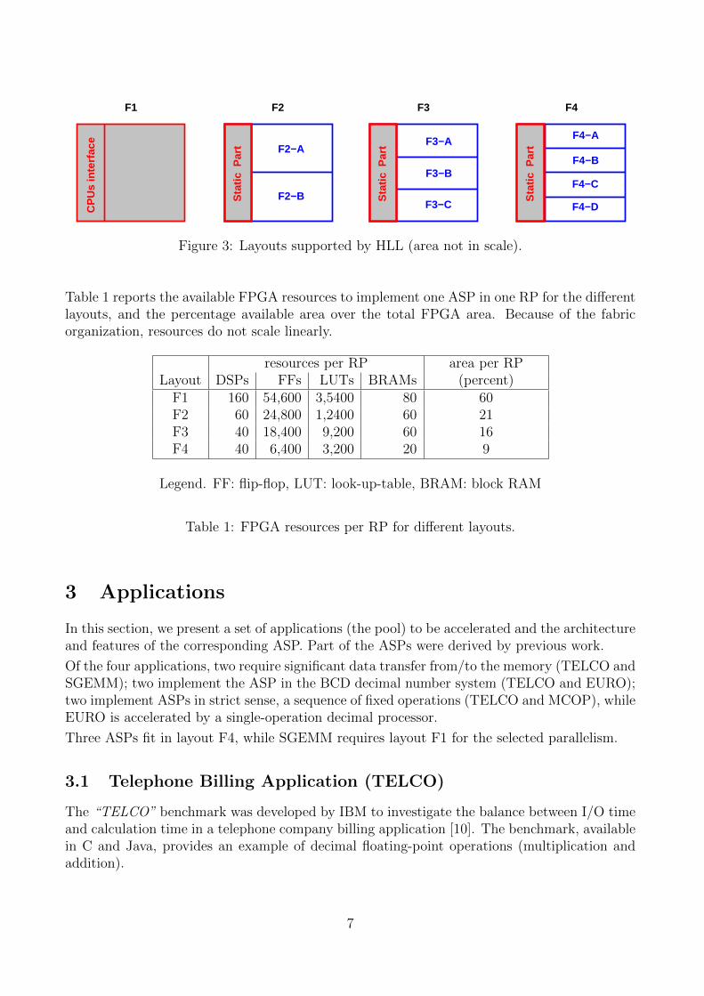
The supported architecture layouts in HLL are sketched in Fig. 3. Switching among layoutsrequires a static reconfiguration.
6
CP
Us
inte
rfac
e
F1 F2 F4F3
Sta
tic P
art
Sta
tic P
art
Sta
tic P
art F2−A
F2−B
F3−A
F3−B
F3−C
F4−A
F4−B
F4−C
F4−D
Figure 3: Layouts supported by HLL (area not in scale).
Table 1 reports the available FPGA resources to implement one ASP in one RP for the differentlayouts, and the percentage available area over the total FPGA area. Because of the fabricorganization, resources do not scale linearly.
resources per RP area per RPLayout DSPs FFs LUTs BRAMs (percent)
F1 160 54,600 3,5400 80 60F2 60 24,800 1,2400 60 21F3 40 18,400 9,200 60 16F4 40 6,400 3,200 20 9
Legend. FF: flip-flop, LUT: look-up-table, BRAM: block RAM
Table 1: FPGA resources per RP for different layouts.
3 Applications
In this section, we present a set of applications (the pool) to be accelerated and the architectureand features of the corresponding ASP. Part of the ASPs were derived by previous work.
Of the four applications, two require significant data transfer from/to the memory (TELCO andSGEMM); two implement the ASP in the BCD decimal number system (TELCO and EURO);two implement ASPs in strict sense, a sequence of fixed operations (TELCO and MCOP), whileEURO is accelerated by a single-operation decimal processor.
Three ASPs fit in layout F4, while SGEMM requires layout F1 for the selected parallelism.
3.1 Telephone Billing Application (TELCO)
The “TELCO” benchmark was developed by IBM to investigate the balance between I/O timeand calculation time in a telephone company billing application [10]. The benchmark, availablein C and Java, provides an example of decimal floating-point operations (multiplication andaddition).
7
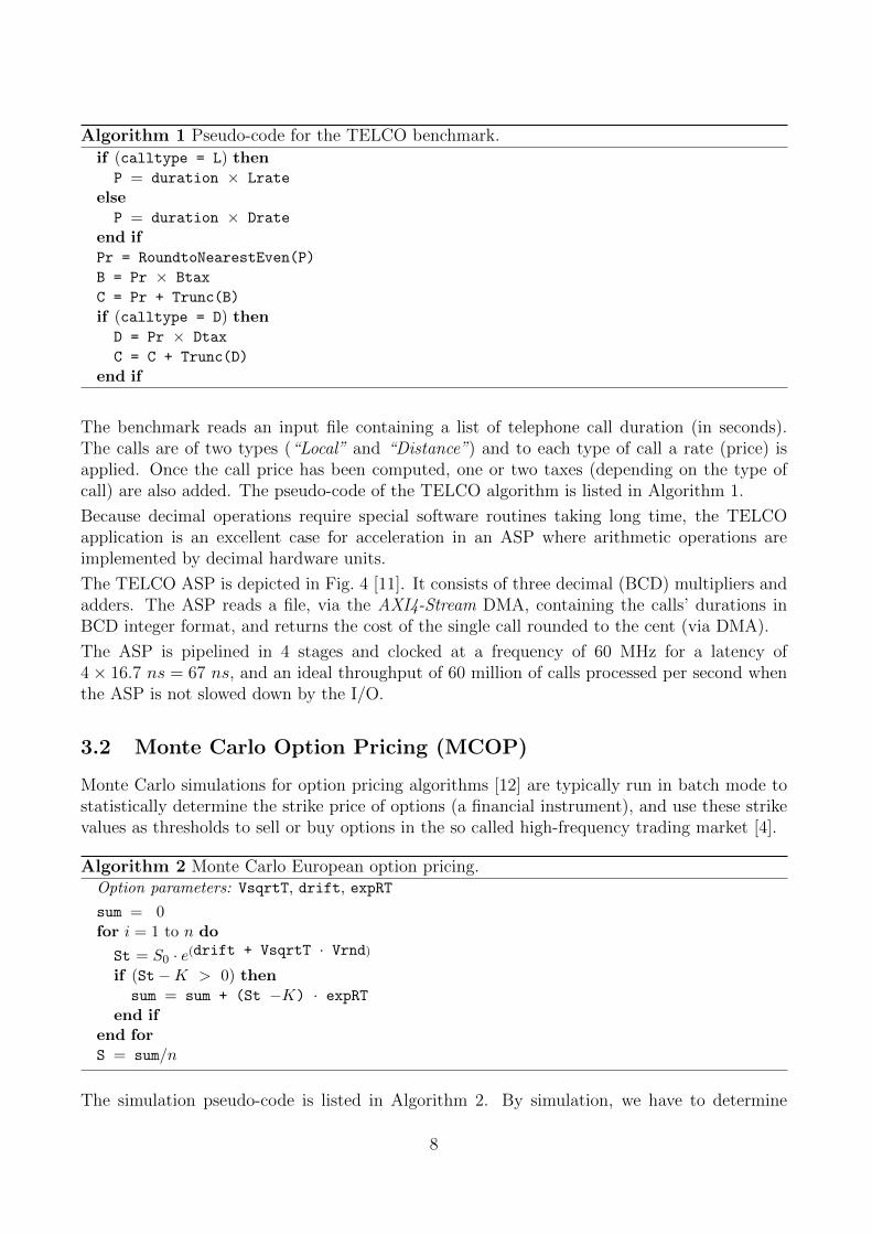
Algorithm 1 Pseudo-code for the TELCO benchmark.if (calltype = L) then
P = duration × Lrate
elseP = duration × Drate
end ifPr = RoundtoNearestEven(P)
B = Pr × Btax
C = Pr + Trunc(B)
if (calltype = D) thenD = Pr × Dtax
C = C + Trunc(D)
end if
The benchmark reads an input file containing a list of telephone call duration (in seconds).The calls are of two types (“Local” and “Distance”) and to each type of call a rate (price) isapplied. Once the call price has been computed, one or two taxes (depending on the type ofcall) are also added. The pseudo-code of the TELCO algorithm is listed in Algorithm 1.
Because decimal operations require special software routines taking long time, the TELCOapplication is an excellent case for acceleration in an ASP where arithmetic operations areimplemented by decimal hardware units.
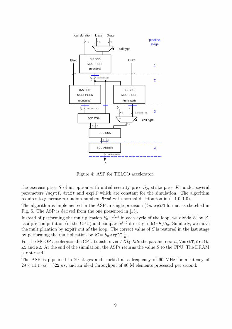
The TELCO ASP is depicted in Fig. 4 [11]. It consists of three decimal (BCD) multipliers andadders. The ASP reads a file, via the AXI4-Stream DMA, containing the calls’ durations inBCD integer format, and returns the cost of the single call rounded to the cent (via DMA).
The ASP is pipelined in 4 stages and clocked at a frequency of 60 MHz for a latency of4× 16.7 ns = 67 ns, and an ideal throughput of 60 million of calls processed per second whenthe ASP is not slowed down by the I/O.
3.2 Monte Carlo Option Pricing (MCOP)
Monte Carlo simulations for option pricing algorithms [12] are typically run in batch mode tostatistically determine the strike price of options (a financial instrument), and use these strikevalues as thresholds to sell or buy options in the so called high-frequency trading market [4].
Algorithm 2 Monte Carlo European option pricing.Option parameters: VsqrtT, drift, expRT
sum = 0for i = 1 to n do
St = S0 · e(drift + VsqrtT · Vrnd)if (St−K > 0) then
sum = sum + (St −K) · expRTend if
end forS = sum/n
The simulation pseudo-code is listed in Algorithm 2. By simulation, we have to determine
8
0 1
BCD ADDER
BCD CSA
8 8
BCD CSA
8 8
Btax Dtax
b d
pr
c
0
5
xxxxxx.xx
xxxxxx.xx
xxxxxx.xx
xxxxxx.xx
MULTIPLIER
8x5 BCD
(truncated)
MULTIPLIER
8x5 BCD
(truncated)
call type8
5
1
2
3
4
pipelinestage
8
0 1
Lrate Drate
6 5 5
call type
call duration
MULTIPLIER
6x5 BCD
(rounded)
Figure 4: ASP for TELCO accelerator.
the exercise price S of an option with initial security price S0, strike price K, under severalparameters VsqrtT, drift and expRT which are constant for the simulation. The algorithmrequires to generate n random numbers Vrnd with normal distribution in (−1.0, 1.0).
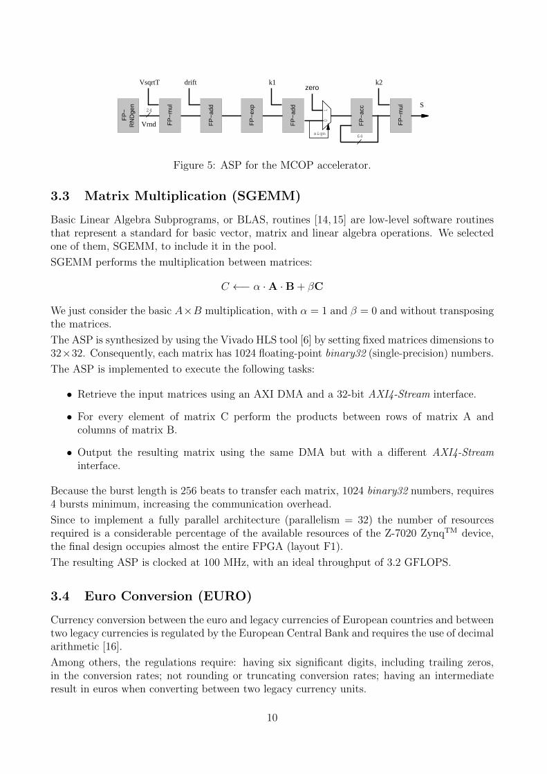
The algorithm is implemented in the ASP in single-precision (binary32) format as sketched inFig. 5. The ASP is derived from the one presented in [13].
Instead of performing the multiplication S0 · e(...) in each cycle of the loop, we divide K by S0
as a pre-computation (in the CPU) and compare e(...) directly to k1=K/S0. Similarly, we movethe multiplication by expRT out af the loop. The correct value of S is restored in the last stageby performing the multiplication by k2= S0·expRT· 1n .
For the MCOP accelerator the CPU transfers via AXI4-Lite the parameters: n, VsqrtT, drift,k1 and k2. At the end of the simulation, the ASPs returns the value S to the CPU. The DRAMis not used.
The ASP is pipelined in 29 stages and clocked at a frequency of 90 MHz for a latency of29× 11.1 ns = 322 ns, and an ideal throughput of 90 M elements processed per second.
9
FP
−ad
d
FP
−m
ul
FP
−ex
p
FP
−ac
c
FP
−R
ND
gen
FP
−m
ul
FP
−ad
d
01
zero
sign
VsqrtT drift k1 k2
S24
64
Vrnd
Figure 5: ASP for the MCOP accelerator.
3.3 Matrix Multiplication (SGEMM)
Basic Linear Algebra Subprograms, or BLAS, routines [14, 15] are low-level software routinesthat represent a standard for basic vector, matrix and linear algebra operations. We selectedone of them, SGEMM, to include it in the pool.
SGEMM performs the multiplication between matrices:
C ←− α ·A ·B + βC
We just consider the basic A×B multiplication, with α = 1 and β = 0 and without transposingthe matrices.
The ASP is synthesized by using the Vivado HLS tool [6] by setting fixed matrices dimensions to32×32. Consequently, each matrix has 1024 floating-point binary32 (single-precision) numbers.
The ASP is implemented to execute the following tasks:
• Retrieve the input matrices using an AXI DMA and a 32-bit AXI4-Stream interface.
• For every element of matrix C perform the products between rows of matrix A andcolumns of matrix B.
• Output the resulting matrix using the same DMA but with a different AXI4-Streaminterface.
Because the burst length is 256 beats to transfer each matrix, 1024 binary32 numbers, requires4 bursts minimum, increasing the communication overhead.
Since to implement a fully parallel architecture (parallelism = 32) the number of resourcesrequired is a considerable percentage of the available resources of the Z-7020 ZynqTM device,the final design occupies almost the entire FPGA (layout F1).
The resulting ASP is clocked at 100 MHz, with an ideal throughput of 3.2 GFLOPS.
3.4 Euro Conversion (EURO)
Currency conversion between the euro and legacy currencies of European countries and betweentwo legacy currencies is regulated by the European Central Bank and requires the use of decimalarithmetic [16].
Among others, the regulations require: having six significant digits, including trailing zeros,in the conversion rates; not rounding or truncating conversion rates; having an intermediateresult in euros when converting between two legacy currency units.
10
We extend these rules, to the generic case of conversion between euro and any other currency,not only legacy currencies, according to a conversion table Rate that it is assumed constant2
Conversion operations are stored in format:FROM TO amount.
The operations for euro conversion are shown in Table 2 [16], and in Algorithm 3.
FROM TO OperationEUR currency amount×Rate[TO]
currency EUR amount/Rate[FROM ]
Table 2: Operations for euro conversion.
Algorithm 3 Euro conversion.Read conversion rates in Rate[currency]
for entries in file doif (FROM = "EUR") then
// convert from EUR to “currency”value = amount × Rate[TO]
else// convert from “currency” to EURvalue = amount / Rate[FROM]
end ifend for
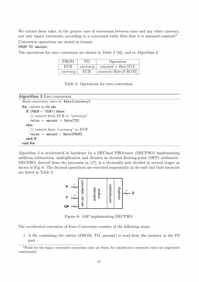
Algorithm 3 is accelerated in hardware by a DECimal PROcessor (DECPRO) implementingaddition/subtraction, multiplication and division in decimal floating-point (DFP) arithmetic.DECPRO, derived from the processor in [17], is a decimal64 unit divided in several stages asshown in Fig. 6. The decimal operations are executed sequentially in the unit and their latenciesare listed in Table 3.
se
t−u
p /
alig
nm
en
t
arith
me
tic
en
gin
e
no
rma
liza
tio
n
rou
nd
ing
64
8
64
64
OP
X
Y
Z
Figure 6: ASP implementing DECPRO.
The accelerated execution of Euro Conversion consists of the following steps:
1. A file containing the entries (FROM, TO, amount) is read from the memory in the PSpart.
2While for the legacy currencies conversion rates are fixed, for outside-euro currencies rates are negotiatedcontinuously.
11
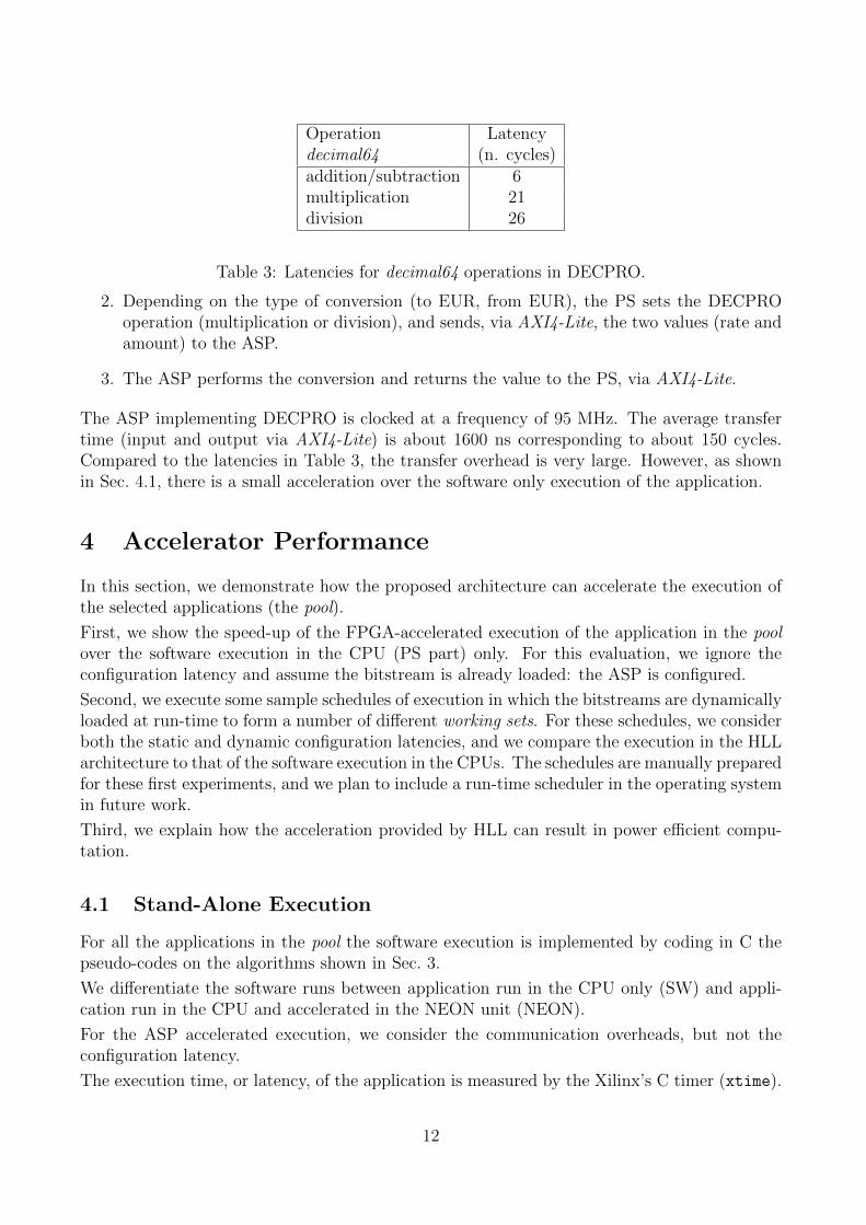
Operation Latencydecimal64 (n. cycles)addition/subtraction 6multiplication 21division 26
Table 3: Latencies for decimal64 operations in DECPRO.
2. Depending on the type of conversion (to EUR, from EUR), the PS sets the DECPROoperation (multiplication or division), and sends, via AXI4-Lite, the two values (rate andamount) to the ASP.
3. The ASP performs the conversion and returns the value to the PS, via AXI4-Lite.
The ASP implementing DECPRO is clocked at a frequency of 95 MHz. The average transfertime (input and output via AXI4-Lite) is about 1600 ns corresponding to about 150 cycles.Compared to the latencies in Table 3, the transfer overhead is very large. However, as shownin Sec. 4.1, there is a small acceleration over the software only execution of the application.
4 Accelerator Performance
In this section, we demonstrate how the proposed architecture can accelerate the execution ofthe selected applications (the pool).
First, we show the speed-up of the FPGA-accelerated execution of the application in the poolover the software execution in the CPU (PS part) only. For this evaluation, we ignore theconfiguration latency and assume the bitstream is already loaded: the ASP is configured.
Second, we execute some sample schedules of execution in which the bitstreams are dynamicallyloaded at run-time to form a number of different working sets. For these schedules, we considerboth the static and dynamic configuration latencies, and we compare the execution in the HLLarchitecture to that of the software execution in the CPUs. The schedules are manually preparedfor these first experiments, and we plan to include a run-time scheduler in the operating systemin future work.
Third, we explain how the acceleration provided by HLL can result in power efficient compu-tation.
4.1 Stand-Alone Execution
For all the applications in the pool the software execution is implemented by coding in C thepseudo-codes on the algorithms shown in Sec. 3.
We differentiate the software runs between application run in the CPU only (SW) and appli-cation run in the CPU and accelerated in the NEON unit (NEON).
For the ASP accelerated execution, we consider the communication overheads, but not theconfiguration latency.
The execution time, or latency, of the application is measured by the Xilinx’s C timer (xtime).
12
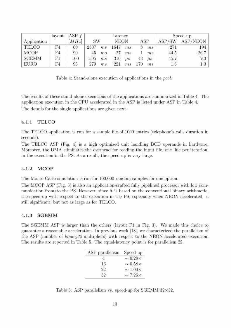
layout ASP f Latency Speed-upApplication [MHz] SW NEON ASP ASP/SW ASP/NEONTELCO F4 60 2307 ms 1647 ms 8 ms 271 194MCOP F4 90 45 ms 27 ms 1 ms 44.5 26.7SGEMM F1 100 1.95 ms 310 µs 43 µs 45.7 7.3EURO F4 95 279 ms 221 ms 170 ms 1.6 1.3
Table 4: Stand-alone execution of applications in the pool.
The results of these stand-alone executions of the applications are summarized in Table 4. Theapplication execution in the CPU accelerated in the ASP is listed under ASP in Table 4.
The details for the single applications are given next.
4.1.1 TELCO
The TELCO application is run for a sample file of 1000 entries (telephone’s calls duration inseconds).
The TELCO ASP (Fig. 4) is a high optimized unit handling BCD operands in hardware.Moreover, the DMA eliminates the overhead for reading the input file, one line per iteration,in the execution in the PS. As a result, the speed-up is very large.
4.1.2 MCOP
The Monte Carlo simulation is run for 100,000 random samples for one option.
The MCOP ASP (Fig. 5) is also an application-crafted fully pipelined processor with low com-munication from/to the PS. However, since it is based on the conventional binary arithmetic,the speed-up with respect to the execution in the PS, especially when NEON accelerated, isstill significant, but not as large as for TELCO.
4.1.3 SGEMM
The SGEMM ASP is larger than the others (layout F1 in Fig. 3). We made this choice toguarantee a reasonable acceleration. In previous work [18], we characterized the parallelism ofthe ASP (number of binary32 multipliers) with respect to the NEON accelerated execution.The results are reported in Table 5. The equal-latency point is for parallelism 22.
ASP parallelism Speed-up4 ∼ 0.28×16 ∼ 0.58×22 ∼ 1.00×32 ∼ 7.26×
Table 5: ASP parallelism vs. speed-up for SGEMM 32×32.
13
The latency reported in Table 4 is for one matrix product, i.e., 1024 binary32 multiply-addoperations.
4.1.4 EURO
The execution of EURO (refer to Algorithm 3) requires to read the triple (FROM, TO, amount)from an ASCII file. Therefore, for each amount to be converted, four C statements are executed:
1. one line of the input file is parsed: sscanf();
2. the string containing amount is converted in decimal64: by the C functiondecDoubleFromString() [10];
3. the operation (multiplication or division) is selected: if (...);
4. the operation is executed:
- by the C function decDoubleMultiply(), or decDoubleDivide() in SW and NEON;
- by transferring via AXI4-Lite OP, rate and amount to DECPRO (Fig. 6) in ASP.
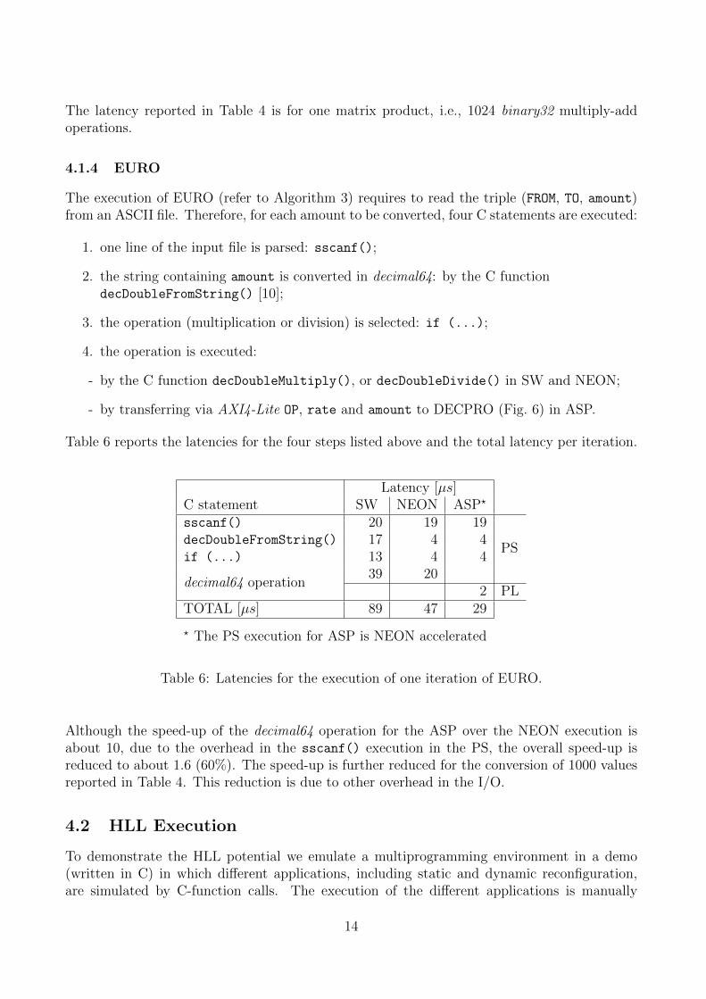
Table 6 reports the latencies for the four steps listed above and the total latency per iteration.
Latency [µs]C statement SW NEON ASP?
sscanf() 20 19 19
PSdecDoubleFromString() 17 4 4if (...) 13 4 4
decimal64 operation39 20
2 PLTOTAL [µs] 89 47 29
? The PS execution for ASP is NEON accelerated
Table 6: Latencies for the execution of one iteration of EURO.
Although the speed-up of the decimal64 operation for the ASP over the NEON execution isabout 10, due to the overhead in the sscanf() execution in the PS, the overall speed-up isreduced to about 1.6 (60%). The speed-up is further reduced for the conversion of 1000 valuesreported in Table 4. This reduction is due to other overhead in the I/O.
4.2 HLL Execution
To demonstrate the HLL potential we emulate a multiprogramming environment in a demo(written in C) in which different applications, including static and dynamic reconfiguration,are simulated by C-function calls. The execution of the different applications is manually
14
F4-A
F4-B
F4-C
F4-D
0ms 20ms 40ms 60ms 80ms 100ms 120ms 140ms 160ms
LOAD MCOP via PCAP TELCO 60MHz(1000 Calls) IDLE EURO CONVERTER 95MHz (100 Conversions)
MCOP 90MHz (9 Stock Options with n=1M)
TELCO 60MHz(1000 Calls)
TELCO 60MHz(1000 Calls)
IDLE
IDLE
IDLE
LOAD SGEMMvia PCAP
MCOP 90MHz (7 Stock Options with n=1M)
LOAD MCOP via PCAP
LOAD MCOP via PCAP
LOAD MCOP via PCAP
MCOP 90MHz (5 Stock Options with n=1M)
MCOP 90MHz LOAD TELCO via PCAP
LOAD TELCO via PCAP
LOAD TELCO via PCAP
LOAD TELCO via PCAP
TELCO 60MHz(1000 Calls)
SGEMM
MCOP 90MHz
LOAD MCOP via PCAP
LOAD MCOP via PCAP
LOAD MCOP via PCAP
LOAD MCOP via PCAP
MCOP 90MHz
MCOP 90MHz
MCOP 90MHz
MCOP 90MHz
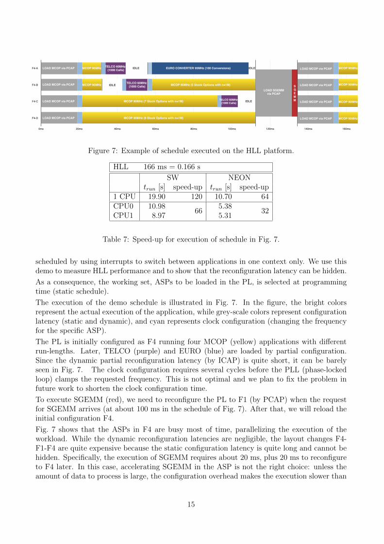
Figure 7: Example of schedule executed on the HLL platform.
HLL 166 ms = 0.166 s
SW NEONtrun [s] speed-up trun [s] speed-up
1 CPU 19.90 120 10.70 64CPU0 10.98
665.38
32CPU1 8.97 5.31
Table 7: Speed-up for execution of schedule in Fig. 7.
scheduled by using interrupts to switch between applications in one context only. We use thisdemo to measure HLL performance and to show that the reconfiguration latency can be hidden.
As a consequence, the working set, ASPs to be loaded in the PL, is selected at programmingtime (static schedule).
The execution of the demo schedule is illustrated in Fig. 7. In the figure, the bright colorsrepresent the actual execution of the application, while grey-scale colors represent configurationlatency (static and dynamic), and cyan represents clock configuration (changing the frequencyfor the specific ASP).
The PL is initially configured as F4 running four MCOP (yellow) applications with differentrun-lengths. Later, TELCO (purple) and EURO (blue) are loaded by partial configuration.Since the dynamic partial reconfiguration latency (by ICAP) is quite short, it can be barelyseen in Fig. 7. The clock configuration requires several cycles before the PLL (phase-lockedloop) clamps the requested frequency. This is not optimal and we plan to fix the problem infuture work to shorten the clock configuration time.
To execute SGEMM (red), we need to reconfigure the PL to F1 (by PCAP) when the requestfor SGEMM arrives (at about 100 ms in the schedule of Fig. 7). After that, we will reload theinitial configuration F4.
Fig. 7 shows that the ASPs in F4 are busy most of time, parallelizing the execution of theworkload. While the dynamic reconfiguration latencies are negligible, the layout changes F4-F1-F4 are quite expensive because the static configuration latency is quite long and cannot behidden. Specifically, the execution of SGEMM requires about 20 ms, plus 20 ms to reconfigureto F4 later. In this case, accelerating SGEMM in the ASP is not the right choice: unless theamount of data to process is large, the configuration overhead makes the execution slower than
15
F4-A
F4-B
F4-C
F4-D
60ms 80ms 100ms 120ms
EURO CONVERTER 95MHz (100 Conversions)
MCOP 90MHz
TELCO 60MHz(1000 Calls)MCOP 90MHz
MCOP 90MHz
MCOP 90MHz
MCOP 90MHz
PS SGEMM
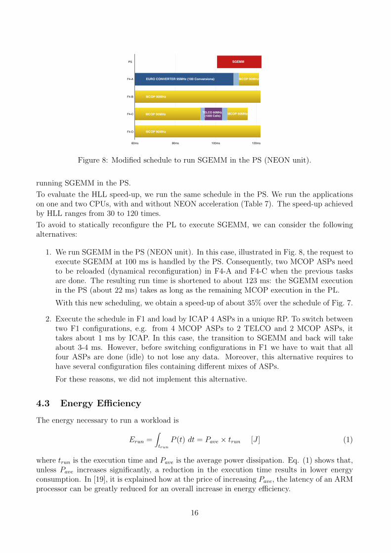
Figure 8: Modified schedule to run SGEMM in the PS (NEON unit).
running SGEMM in the PS.
To evaluate the HLL speed-up, we run the same schedule in the PS. We run the applicationson one and two CPUs, with and without NEON acceleration (Table 7). The speed-up achievedby HLL ranges from 30 to 120 times.
To avoid to statically reconfigure the PL to execute SGEMM, we can consider the followingalternatives:
1. We run SGEMM in the PS (NEON unit). In this case, illustrated in Fig. 8, the request toexecute SGEMM at 100 ms is handled by the PS. Consequently, two MCOP ASPs needto be reloaded (dynamical reconfiguration) in F4-A and F4-C when the previous tasksare done. The resulting run time is shortened to about 123 ms: the SGEMM executionin the PS (about 22 ms) takes as long as the remaining MCOP execution in the PL.
With this new scheduling, we obtain a speed-up of about 35% over the schedule of Fig. 7.
2. Execute the schedule in F1 and load by ICAP 4 ASPs in a unique RP. To switch betweentwo F1 configurations, e.g. from 4 MCOP ASPs to 2 TELCO and 2 MCOP ASPs, ittakes about 1 ms by ICAP. In this case, the transition to SGEMM and back will takeabout 3-4 ms. However, before switching configurations in F1 we have to wait that allfour ASPs are done (idle) to not lose any data. Moreover, this alternative requires tohave several configuration files containing different mixes of ASPs.
For these reasons, we did not implement this alternative.
4.3 Energy Efficiency
The energy necessary to run a workload is
Erun =∫trun
P (t) dt = Pave × trun [J ] (1)
where trun is the execution time and Pave is the average power dissipation. Eq. (1) shows that,unless Pave increases significantly, a reduction in the execution time results in lower energyconsumption. In [19], it is explained how at the price of increasing Pave, the latency of an ARMprocessor can be greatly reduced for an overall increase in energy efficiency.
16
The ZedBoard hosting the Zynq SoC is equipped with current-sense pin-headers to measure thepower dissipation of the whole board. We measured an average power dissipation 3.7 W (onlyone CPU plus NEON, no PL configured) and 4.1 W to run the demo schedule on CPU+ASPs.Clearly, this measurement is too coarse to evaluate the efficiency of HLL on the Zynq platform.
Therefore, we modeled the power dissipation in the SoC as follows. We assume three contribu-tions in the PL:
• Pstat the static power dissipation, that is the power dissipated by the SoC when powered.
• Pidle the dynamic power dissipation when the PL is not computing. This includes theswitching activity in the clock network in the PL.
• P PLcomp the computation power, that is the dynamic power dissipation in the PL when
ASPs are executing the applications.
By the above measurements, P PLcomp is about 400 mW for executing the demo schedule. More-
over, according to the floorplan information provided by Vivado, the PL takes about 80% of thedie area while the PS takes about 20%. By the conservative assumption that the gate densityand the switching activity is equally distributed on the die3, we estimate the PS to dissipateabout 100 mW (i.e., 20
80· 400 mW ) when clocked at the same frequency of the PL (100 MHz).
However, the ARM cores are clocked at 666 MHz, therefore, we estimate the computation powerin the PS to be P PS
comp = 666 mW .
In conclusion, the computation power of the software execution is PCPU = P PScomp/2 = 0.33 W
per core, and the computation power of the accelerated execution is PHLL = PCPU + P PLcomp =
= 0.73 W (worst case scenario for HLL).
By combining these estimates with the latencies in Table 7, we obtain:
ECPU = 0.33× 10.70 = 3.56 J (one core)ECPU = 0.66× 5.38 = 3.56 J (two cores)EHLL = 0.73× 0.166 = 0.12 J
with a HLL energy efficiency factor of about 30 times.
5 Conclusions and Future Work
We have presented the hardware architecture to implement accelerators by dynamically-loadedhardware libraries, or HLL. We described the physical implementation of HLL and explainedthe general framework.
Moreover, we provided an example of a pool of applications representing a generic workload,and we presented a manually-constructed schedule to demonstrate that we can reach speed-up between 30 and 120 times, and a power efficiency of about 30 times better, over the puresoftware execution.
In future work, we will address the integration of HLL in the operating system, which will enablethe full deployment of the technology. Moreover, we will devise a systematic way to profile
3In reality, the gate density is higher in the PS.
17
applications and develop ASPs, and to include extensive testing of configuration bitstreams totest both the correct configuration of the ASP and the runtime performance.
References
[1] S. Patel and W.-M. W. Hwu, “Accelerator Architectures,” IEEE Micro magazine, vol. 28,pp. 4–12, July/Aug. 2008.
[2] H. Esmaeilzadeh, T. Cao, X. Yang, S. M. Blackburn, and K. S. McKinley, “What isHappening to Power, Performance, and Software?” IEEE Micro, vol. 32, no. 3, pp. 110–121, May-June 2012.
[3] A. Putnam et al., “A reconfigurable fabric for accelerating large-scale datacenter services,”in Proc. of ACM/IEEE 41st International Symposium on Computer Architecture (ISCA),Jun. 2014, pp. 13–24.
[4] J. W. Lockwood, A. Gupte, N. Mehta, M. Blott, T. English, and K. A. Vissers, “ALow-Latency Library in FPGA Hardware for High-Frequency Trading (HFT),” in HotInterconnects’12, 2012, pp. 9–16.
[5] F. de Dinechin and B. Pasca, “Designing custom arithmetic data paths with FloPoCo,”IEEE Design & Test of Computers, vol. 28, no. 4, pp. 18–27, Jul. 2011.
[6] Xilinx. (2015) UG902 – Vivado Design Suite User Guide –High-Level Synthesis. [Online]. Available: http://www.xilinx.com/ sup-port/documentation/sw manuals/xilinx2012 2/ug902-vivado-high-level-synthesis.pdf
[7] J. Burt, “Intel Begins Shipping Xeon Chips With FPGA Accelerators,” eWeek, Apr.2016. [Online]. Available: http://www.eweek.com/servers/ intel-begins-shipping-xeon-chips-with-fpga-accelerators.html
[8] ARM. (2012) Cortex-A9 Technical Reference Manual. Version r4p1.
[9] K. Vipin and S. A. Fahmy, “ZyCAP: Efficient Partial Reconfiguration Management on theXilinx Zynq,” IEEE Embedded Systems Letters, vol. 6, no. 3, pp. 41–44, Sept 2014.
[10] IBM Corporation. ”The ”telco” benchmark”. [Online]. Available:http://speleotrove.com/decimal/telco.html
[11] J. K. Toft and A. Nannarelli, “Energy Efficient FPGA based Hardware Accelerators forFinancial Applications,” in Proc. of the 32th NORCHIP Conference, Nov. 2014.
[12] J. C. Hull, Options, Futures and other Derivatives, 8th ed. Prentice Hall, 2012.
[13] J. S. Hegner, J. Sindholt, and A. Nannarelli, “Design of Power Efficient FPGA based Hard-ware Accelerators for Financial Applications,” in Proc. of the 30th NORCHIP Conference,Nov. 2012.
18
[14] C. L. Lawson, R. J. Hanson, D. R. Kincaid, and F. T. Krogh, “Basic Linear AlgebraSubprograms for Fortran Usage,” ACM Trans. Math. Softw., vol. 5, no. 3, pp. 308–323,1979.
[15] L. Zhuo and V. K. Prasanna, “Design tradeoffs for BLAS operations on reconfigurablehardware,” in International Conference on Parallel Processing, ICPP 2005, June 2005,pp. 78–86.
[16] L. K. Wang, C. Tsen, M. J. Schulte, and D. Jhalani, “Benchmarks and performance anal-ysis of decimal floating-point applications,” in 25th International Conference on ComputerDesign, ICCD 2007, Oct 2007, pp. 164–170.
[17] A. Nannarelli, “Decimal engine for energy-efficient multicore processors,” in 2014 22ndInternational Conference on Very Large Scale Integration (VLSI-SoC), Oct. 2014, pp. 1–6.
[18] G. C. Cardarilli, L. D. Carlo, A. Nannarelli, F. M. Pandolfi, and M. Re, “A framework fordynamically-loaded hardware library (HLL) in FPGA acceleration,” in IEEE InternationalSymposium on Signal Processing and Information Technology (ISSPIT), Dec. 2015, pp.291–296.
[19] D. Lutz, “ARM FPUs: Low Latency is Low Energy,” in Special Session at the22nd IEEE Symposium in Computer Arithmetic, June 2015. [Online]. Available:http://arith22.gforge.inria.fr/slides/s1-lutz.pdf
19