FP7 { 215535 D1.2.1 Initial Operational Framework
44
LarKC The Large Knowledge Collider a platform for large scale integrated reasoning and Web-search FP7 – 215535 D1.2.1 Initial Operational Framework Gaston Tagni (VUA), Annette ten Teije (VUA) Frank van Harmelen (VUA), Barry Bishop (UIBK) Mick Kerrigan (UIBK), Georgina Gallizo (HLRS) Axel Tenschert (HLRS), Luka Bradesko (CycEur), Vassil Momtchev (OntoText), Atanas Kiryakov (OntoText) Document Identifier: LarKC/2008/D1.2.1 Class Deliverable: LarKC EU-IST-2008-215535 Version: version 1.0.0 Date: October 30, 2008 State: final Distribution: public
Transcript of FP7 { 215535 D1.2.1 Initial Operational Framework

LarKCThe Large Knowledge Collider
a platform for large scale integrated reasoning and Web-search
FP7 – 215535
D1.2.1
Initial Operational Framework
Gaston Tagni (VUA), Annette ten Teije (VUA)Frank van Harmelen (VUA), Barry Bishop (UIBK)Mick Kerrigan (UIBK), Georgina Gallizo (HLRS)
Axel Tenschert (HLRS), Luka Bradesko (CycEur),
Vassil Momtchev (OntoText), Atanas Kiryakov (OntoText)
Document Identifier: LarKC/2008/D1.2.1Class Deliverable: LarKC EU-IST-2008-215535Version: version 1.0.0Date: October 30, 2008State: finalDistribution: public

Initial Operational Framework
Executive Summary
This document reports on the ongoing work being conducted as part of the ac-tivities in WP1 and WP5 regarding the design and implementation of the LarKCplatform. It provides a description of the first version of the platform and its un-derlying architecture. More specifically, we define the five types of plug-ins thatconstitute the platform and for each of them a description of its behaviour andinterfaces (I/O types) is provided. Additionally, we provide a description of thedifferent usage phases of the platform, i.e. a description of how different users willinteract with the platform. The document also introduces the datamodel adoptedby the platform. To help validate the initial architecture we have studied thethree uses cases considered in LarKC and identified how the different use casescan be supported by the current version of the platform. We also report on asimple LarKC pipeline that has been built to validate the design decisions fromthis document. This document also reports on some of the discussions that havetaken place during the design of the first version of the platform. Architecturaldesign aspects such as remote invocation, support for anytime behaviour and datastorage layer are discussed. We also describe a prototype implementation of thecurrent version of the platform.
Deliverable 1.2.1 i

Initial Operational Framework
Document Information
IST ProjectNumber
FP7 – 215535 Acronym LarKC
Full Title Large Knowledge ColliderProject URL http://www.larkc.eu/Document URLEU Project Officer Stefano Bertolo
Deliverable Number 1.2.1 Title Initial Operational FrameworkWork Package Number 1 Title Conceptual Framework
Date of Delivery Contractual M7 Actual 31-Oct-08Status version 1.0.0 final �Nature prototype � report � dissemination �DisseminationLevel
public � consortium �
Authors (Partner)
Gaston Tagni (VUA), Annette ten Teije (VUA), Frank van Harmelen (VUA), MickKerrigan (UIBK), Barry Bishop (UIBK), Georgina Gallizo (HLRS), Axel Tenschert(HLRS), Luka Bradesko (CycEur), Vassil Momtchev (OntoText), Atanas Kiryakov(OntoText)
Resp. AuthorGaston Tagni (VUA) E-mail [email protected] VUA Phone +31 (20) 59-87753
Abstract(for dissemination)
This document reports on the ongoing work being conducted as part of theactivities in WP1 and WP5 regarding the design and implementation of the LarKCplatform. It provides a description of the first version of the platform and itsunderlying architecture. More specifically, we define the five types of plug-ins thatconstitute the platform and for each of them a description of its behaviour andinterfaces (I/O types) is provided. Additionally, we provide a description of thedifferent usage phases of the platform, i.e. a description of how different userswill interact with the platform. The document also introduces the datamodeladopted by the platform. To help validate the initial architecture we have studiedthe three uses cases considered in LarKC and identified how the different usecases can be supported by the current version of the platform. We also report ona simple LarKC pipeline that has been built to validate the design decisions fromthis document. This document also reports on some of the discussions that havetaken place during the design of the first version of the platform. Architecturaldesign aspects such as remote invocation, support for anytime behaviour and datastorage layer are discussed. We also describe a prototype implementation of thecurrent version of the platform.
Keywords LarKC platform, LarKC Plug-ins, Web scale reasoning, Semantic Web
Deliverable 1.2.1 ii
Initial Operational Framework
Project Consortium Information
Acronym Partner ContactSemantic Technology Institute Innsbruckhttp://www.sti-innsbruck.at
STI Prof. Dr. Dieter FenselSemantic Technology Institute (STI)Innsbruck, AustriaE-mail: [email protected]
AstraZeneca ABhttp://www.astrazeneca.com/
ASTRAZENECA Bosse AnderssonAstraZenecaLund, SwedenE-mail: [email protected]
CEFRIEL SCRL.http://www.cefriel.it/
CEFRIEL Emanuele Della ValleCEFRIEL SCRL.Milano, ItalyE-mail: [email protected]
CYCORP, RAZISKOVANJE IN EKSPERI-MENTALNI RAZVOJ D.O.O.http://cyceurope.com/
CYCORP Michael WitbrockCYCORP, RAZISKOVANJE IN EKSPERIMEN-TALNI RAZVOJ D.O.O.,Ljubljana, SloveniaE-mail: [email protected]
Hchstleistungsrechenzentrum, UniversitaetStuttgarthttp://www.hlrs.de/
HLRS Georgina GallizoHchstleistungsrechenzentrum, UniversitaetStuttgartStuttgart, GermanyE-mail : [email protected]
Max-Planck-Institut fr Bildungsforschunghttp://www.mpib-berlin.mpg.de/index_
js.en.htm
MAXPLANCKGESELLSCHDr. Lael Schooler,Max-Planck-Institut fr BildungsforschungBerlin, GermanyE-mail: [email protected]
Ontotext Lab, Sirma Group Corp.http://www.ontotext.com/
ONTO Atanas Kiryakov,Ontotext Lab, Sirma Group Corp.Sofia, BulgariaE-mail: [email protected]
SALTLUX INC.http://www.saltlux.com/EN/main.asp
Saltlux Kono KimSALTLUX INCSeoul, KoreaE-mail: [email protected]
SIEMENS AKTIENGESELLSCHAFThttp://www.siemens.de/
Siemens Dr. Volker TrespSIEMENS AKTIENGESELLSCHAFTMuenchen, GermanyE-mail: [email protected]
THE UNIVERSITY OF SHEFFIELDhttp://www.shef.ac.uk/
Sheffield Prof. Dr. Hamish CunninghamTHE UNIVERSITY OF SHEFFIELDSheffield, UKE-mail: [email protected]
VRIJE UNIVERSITEIT AMSTERDAMhttp://www.vu.nl/
Amsterdam Prof. Dr. Frank van HarmelenVRIJE UNIVERSITEIT AMSTERDAMAmsterdam, NetherlandsE-mail: [email protected]
THE INTERNATIONAL WIC INSTITUTE,BEIJING UNIVERSITY OF TECHNOLOGYhttp://www.iwici.org/
WICI Prof. Dr. Ning ZhongTHE INTERNATIONAL WIC INSTITUTEMabeshi, JapanE-mail: [email protected]
Deliverable 1.2.1 iii
Initial Operational Framework
INTERNATIONAL AGENCY FOR RESEARCHON CANCERhttp://www.iarc.fr/
IARC2 Dr. Paul BrennanINTERNATIONAL AGENCY FOR RESEARCH ONCANCERLyon, FranceE-mail: [email protected]
Deliverable 1.2.1 iv

Initial Operational Framework
Table of Contents
1 Introduction 2
2 The LarKC Platform 42.1 Overview of the LarKC Architecture . . . . . . . . . . . . . . . . . 4
2.1.1 Usage of the LarKC Platform . . . . . . . . . . . . . . . . . 52.2 LarKC Plug-ins . . . . . . . . . . . . . . . . . . . . . . . . . . . . . 6
2.2.1 Identify . . . . . . . . . . . . . . . . . . . . . . . . . . . . . 72.2.2 Transform . . . . . . . . . . . . . . . . . . . . . . . . . . . . 72.2.3 Select . . . . . . . . . . . . . . . . . . . . . . . . . . . . . . 82.2.4 Reason . . . . . . . . . . . . . . . . . . . . . . . . . . . . . . 92.2.5 Decide . . . . . . . . . . . . . . . . . . . . . . . . . . . . . . 9
2.3 Datamodel . . . . . . . . . . . . . . . . . . . . . . . . . . . . . . . . 102.4 Example Scenario . . . . . . . . . . . . . . . . . . . . . . . . . . . . 11
3 Use-case Scenarios 133.1 Use Case WP6: Urban Computing . . . . . . . . . . . . . . . . . . 13
3.1.1 Getting to Milano . . . . . . . . . . . . . . . . . . . . . . . . 133.2 Use Case WP7a: Early Clinical Drug Development . . . . . . . . . 14
3.2.1 Improve Knowledge About Disease and Patients . . . . . . . 143.2.2 Clinical Project Team Working on a New Target . . . . . . . 153.2.3 Identifying Biomarkers and Target Mechanisms . . . . . . . 163.2.4 Signal Evaluation of Adverse Drug Event Reports . . . . . . 17
3.3 Use Case WP7b: Carcinogenesis Research . . . . . . . . . . . . . . 173.3.1 Monograph Production . . . . . . . . . . . . . . . . . . . . . 183.3.2 Genome Wide Association Studies . . . . . . . . . . . . . . . 19
4 Issues Concerning Remote Invocation 204.1 Trust and Security . . . . . . . . . . . . . . . . . . . . . . . . . . . 204.2 Plug-in registration and discovery . . . . . . . . . . . . . . . . . . . 234.3 Heterogeneity . . . . . . . . . . . . . . . . . . . . . . . . . . . . . . 244.4 Data Transfer between remote components . . . . . . . . . . . . . . 254.5 Synchronization and communication between parallel tasks . . . . . 26
5 Support for Anytime Behaviour 275.1 Interface between LarKC and User . . . . . . . . . . . . . . . . . . 28
5.1.1 Callback . . . . . . . . . . . . . . . . . . . . . . . . . . . . . 285.1.2 Queue . . . . . . . . . . . . . . . . . . . . . . . . . . . . . . 30
6 Storage/Data Layer of the Platform 32
7 Prototype implementation: Baby-LarKC 347.1 Scripted DECIDE Plug-in . . . . . . . . . . . . . . . . . . . . . . . 347.2 Self-configuring DECIDE Plug-in . . . . . . . . . . . . . . . . . . . 347.3 Discussion . . . . . . . . . . . . . . . . . . . . . . . . . . . . . . . . 35
7.3.1 Remote Execution . . . . . . . . . . . . . . . . . . . . . . . 357.3.2 Same code between the two test-rigs . . . . . . . . . . . . . 35
Deliverable 1.2.1 v

Initial Operational Framework
7.3.3 Limited scalability because of data transfer . . . . . . . . . . 35
8 Concluding Remarks 36
Deliverable 1.2.1 vi

FP7 – 215535
Deliverable 1.2.1
List of Abbreviations
DUNS Data Universal Numbering SystemGSI Grid Security InfrastructureMPI Message Passing InterfaceOASIS Organization for the Advancement of Structured
Information StandardsOGSA-DAI Open Grid Services Architecture- Data Access IntegrationQoS Quality of ServiceSAML Security Assertion Markup LanguageSOA Service Oriented ArchitectureSOAP Simple Object Access ProtocolUDDI Universal Description, Discovery and IntegrationWSDL Web Service Description LanguageWSS Web Service SecurityUML Unified Modeling LanguageLLD Linked Life DataCPT Clinical Project TeamORDI Ontology Representation and Data Integration FrameworkRDF Resource Description Framework
1

FP7 – 215535
Deliverable 1.2.1
1 Introduction
The principal goal of LarKC is to build a platform for massive distributed in-complete reasoning at Web-scale. Such a platform will be realized through apluggable architecture that gives users the possibility to develop plug-ins in orderto test heuristics and techniques from diverse areas such as Web search, SemanticWeb, databases, machine learning and cognitive science, among others. The plat-form will run on a computing cluster and will also consider alternative computingparadigms such as “computing-at-home”.
This document reports on the ongoing work being conducted as part of theactivities in WP1 and WP5 regarding the design and implementation of the LarKCplatform. It provides a description of the first version of the platform and itsunderlying architecture. More specifically, we define the five types of plug-ins thatconstitute the platform and for each of them a description of its behaviour andinterfaces (I/O types) is provided. Additionally, we provide a description of thedifferent usage phases of the platform, i.e. a description of how different users willinteract with the platform. To help validate the initial architecture we have studiedthe three uses cases considered in LarKC and identified how the different use casescan be supported by the current version of the platform. More specifically, for eachuse case we produced a storyboard describing the key functionality required fromthe LarKC platform in order to implement the use case. Additionally, for everystoryboard we identified a series of plug-ins that can be used for implementingapplications that automate the scenario.
Besides providing a description of the initial architecture this document alsoreports on some of the discussions that have taken place during the design of thefirst version of the platform. In particular we discuss issues concerning remoteinvocation of plug-ins and the support for anytime behaviour. The purpose ofthese discussions is to contribute to the ongoing architectural discussions takingplace in WP1 and WP5 and not as final architectural decisions for the LarKCFramework.
Many issues related to the functionality and design of the platform still remainopen, for example QoS aspects and the data-storage component. These and otherissues will be addressed in a later version of this document due in month 33.
Structure of this document: Chapter 2 introduces the LarKC architectureby providing a description of each of the plug-in types supported by the platform.Each plug-in is described in terms of its API indicating the corresponding input andoutput. This chapter also includes a description of the datamodel adopted by theLarKC platform. In Chapter 3 we provide a description of the use cases consideredin LarKC in terms of the plug-in types defined in Chapter 2. For every use casewe analyze its functional requirements and propose a possible set of plug-ins tosupport the different application scenarios in each of them. Chapter 4 discussesissues concerning remote invocation in the context of the LarKC platform. Weidentify and analyze the remote issues affecting the LarKC framework. We providea preliminary analysis and some initial thoughts about the potential implicationsof this distributed architecture. Some hints are given on current standards andspecifications that could solve the identified issues. In Chapter 5 we tackle anotherimportant issue related to the LarKC platform, namely the support for anytimebehaviour. In particular we discuss different programming models that could be
2

FP7 – 215535
Deliverable 1.2.1
used by LarKC to achieve anytime behaviour. Chapter 7 describes a prototypeimplementation of the current version of the platform. Finally, Chapter 8 concludesthe report.
3

FP7 – 215535
Deliverable 1.2.1
2 The LarKC Platform
This chapter reports on the current state of the LarKC architecture. We providethe definition of the different plug-in types supported by the platform and describethem in terms of their functionality and their API, indicating their input andoutput. This chapter also introduces an overview of the datamodel adopted bythe LarKC platform. We conclude the chapter with an example scenario that showshow the various components can be combined and used to handle user queries.
2.1 Overview of the LarKC Architecture
In order to support massive distributed incomplete reasoning at Web-scale theLarKC platform provides a plug-in based framework. These components or plug-ins can be orchestrated and executed according to the algorithmic schema depictedin Figure 2.1, which corresponds to the pipeline illustrated in Figure 2.2(a). Thisfirst organization of plug-ins however has some limitations. For example, in somesituations it may be necessary to be able to return to any intermediate step in thepipeline after deciding. The pipeline configuration illustrated in Figure 2.2(a) doesnot allow this as the control flows back to a single plug-in after the Decider has beenexecuted. In order to solve this problem a second version of the pipeline allows thecontrol to flow from the Decider to any of the other plug-ins in the previous steps ofthe execution. Figure 2.2(b) illustrates this configuration. This second version stilllacks flexibility in the sense that control decisions may need to be made in betweensteps rather than at the end of the pipeline. For example, in some scenarios it maybe necessary to decide what to do after the Selection plug-in has been executedand before the Reasoner plug-in is executed. Therefore, the third version of thepipeline solves this problem by considering the Decider plug-in as a special typeof component or, “meta”-component, in order to enable quality/resource/controldecisions at any point in the pipeline. Figure 2.2(c) depicts the third and currentlyadopted version of the pipeline. In the picture, the dotted arrows are control-flow,the solid arrows are data-flow. Also, the picture leaves out the data-storage layer,to which all components need to have read/write access. Issues regarding thedata-storage layer will be discussed later in this deliverable and further elaboratedin Deliverable 1.2.2. A description of each plug-in type is given in section 2.2.
repeat
obtain a selection of data; (IDENTIFY)
transform to an appropriate representation; (TRANSFORM)
draw a sample; (SELECT)
reason on the sample; (REASON)
if more time is available (DECIDE)
and/or the result is not good enough (DECIDE)
then increase/decrease the data selection
else exit
end
Figure 2.1: Simple algorithmic schema of the LarKC platform
4

FP7 – 215535
Deliverable 1.2.1
R
I
T
S
D
(a)
R
I
T
S
D
(b)
R
I
T
S
D
(c)
Figure 2.2: LarKC pipeline. Dotted arrows represent control-flow while solid ar-rows are data-flow
2.1.1 Usage of the LarKC Platform
The interaction between users and the LarKC platform will occur according to oneof the following interaction patterns:
• Plug-in Construction: One possible way to interact with the platform isas a plug-in designer/writer. During this phase, designers will write singleplug-ins and deploy them in the platform for future use.
• Platform Configuration: Another interaction scenario involves users (plat-form configuration designers) writing scripts to combine existing plug-ins inorder to solve a given task. For example, users may write a Decider plug-in that combines Selection, Identify, Transform and Reasoning plug-ins toanswer SPARQL queries.
• Platform Invocation: Finally, end users will be able to use the servicesprovided by the platform, i.e. a particular plug-in configuration to executeSPAQRL queries. This interaction pattern also includes application design-ers that implement applications that need to use the services provided bythe platform.
Notice that these user-platform interaction patterns could be combined in aLarKC life cycle involving a construction phase followed by a configuration phaseand finally an invocation phase. Notice also that actors may not interact with theLarKC platform in all the phases, e.g. plug-in writers may not need to configureor use/invoke the platform’s services at all.
In order to facilitate these interaction patterns the LarKC platform will providesupport for:
5

FP7 – 215535
Deliverable 1.2.1
• the implementation of plug-ins by providing access to data repositories, facil-ities for plug-in registration and discovery and by providing a framework (orset of APIs) that allows designers and programmers to implement differenttypes of plug-ins.
• the configuration/combination of existing plug-ins in order to implement rea-soning tasks capable of dealing with large scale and distributed data sources.Such combination of plug-ins will be supported by the definition of a specifictype of plug-in called Decider. A Decider plug-in will contain the specifica-tion of control-flow dependencies among other plug-ins and will be responsi-ble for dealing with other aspects such as remote invocation of plug-ins andanytime behavior.
• the execution of a set of plug-ins on a query and a dataset.
2.2 LarKC Plug-ins
The LarKC API consists of five major plug-in types. In this section we outline thesefive plug-in types, their behavior, and their interfaces. For brevity the interface ofthe classes are described in Java syntax; however it should be noted that this doesnot constrain the language in which plug-ins can be written.
All LarKC share a common super class, which is the Plugin class. This classprovides that functionality which is common to all plug-in types. The interface ofthe Plugin class can be seen in Figure 2.3.
public interface Plugin {
public String getIdentifier();
public MetaData getMetaData();
public QoSInformation getQoSInformation();
public void setInputQuery(Query theQuery);
}
Figure 2.3: The Interface of Plugin
From the above figure it can seen that:
• All plug-ins are identified by a name, which is a string
• Plug-ins provide meta data that states the functionality that they offer
• Plug-ins provide Quality of Service (QoS) information regarding how theyperform the functionality that they offer
• All plug-ins may need access to the initial query and thus a mutator isprovided by specifying this query
6

FP7 – 215535
Deliverable 1.2.1
2.2.1 Identify
Given a specific query the Identify plug-in will identify those Information Sets thatcould be used in order to answer the users query. The interface of the Transformplug-in can be seen in Figure 2.4. This plug-in type was originally named Retrieval(because it provides the functionality required during the retrieval step of thepipeline). However, we decided to rename it to Transform given that its mainfunctionality is to identify possible data sources that can be relevant for answeringa given query.
public interface Identifier extends Plugin{
public Collection<InformationSet> identify(Query theQuery,
Contract theContract);
}
Figure 2.4: The Interface of the Identify plug-in
Thus the Transform plug-in is used for narrowing the scope of a reasoning taskfrom all available information sets to those information sets that are capable ofanswering the query. The plug-in takes a query as input and produces a collectionof Information Sets as output according to the provided contract. The contract isused to specify the dimensions of the output, for example the number of resultsreturned by a given call to the Transform plug-in. An example of an Identify plug-incould for example identify relevant pieces of data from a semantic data index suchas Sindice 1. Such a plug-in would take Triple Pattern Queries as input and giveRDF Graphs as output. These RDF Graphs would match the input Triple Patternquery and thus would contain triples that could be used to answer the users query.
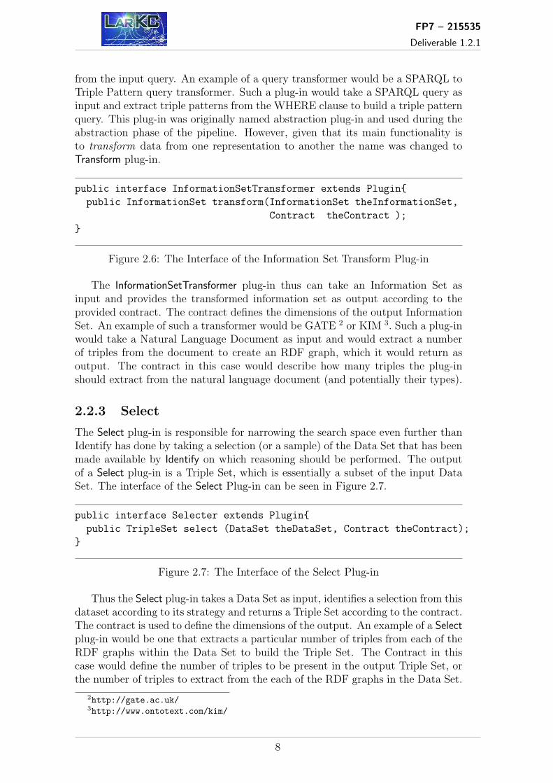
2.2.2 Transform
The Transform plug-in is capable of transforming some piece of data from onerepresentation to another. In the LarKC API we distinguish between the trans-formation of queries and the transformation of Information Sets. Thus there aretwo transform plug-in interfaces within the API, namely the QueryTransformer andInformationSetTransfomer. The interface of each can be seen in Figures 2.5 and 2.6respectively.
public interface QueryTransformer extends Plugin {
public Set<Query> transform(Query theQuery, Contract the Contract);
}
Figure 2.5: The Interface of the Query Transform Plug-in
The QueryTransformer plug-in thus can take a Query as input and produce a setof queries as output according to the provided contract. The contract is used tospecify the dimensions of the output, for example the number of queries to generate
1http://www.sindice.com
7
FP7 – 215535
Deliverable 1.2.1
from the input query. An example of a query transformer would be a SPARQL toTriple Pattern query transformer. Such a plug-in would take a SPARQL query asinput and extract triple patterns from the WHERE clause to build a triple patternquery. This plug-in was originally named abstraction plug-in and used during theabstraction phase of the pipeline. However, given that its main functionality isto transform data from one representation to another the name was changed toTransform plug-in.
public interface InformationSetTransformer extends Plugin{
public InformationSet transform(InformationSet theInformationSet,
Contract theContract );
}
Figure 2.6: The Interface of the Information Set Transform Plug-in
The InformationSetTransformer plug-in thus can take an Information Set asinput and provides the transformed information set as output according to theprovided contract. The contract defines the dimensions of the output InformationSet. An example of such a transformer would be GATE 2 or KIM 3. Such a plug-inwould take a Natural Language Document as input and would extract a numberof triples from the document to create an RDF graph, which it would return asoutput. The contract in this case would describe how many triples the plug-inshould extract from the natural language document (and potentially their types).
2.2.3 Select
The Select plug-in is responsible for narrowing the search space even further thanIdentify has done by taking a selection (or a sample) of the Data Set that has beenmade available by Identify on which reasoning should be performed. The outputof a Select plug-in is a Triple Set, which is essentially a subset of the input DataSet. The interface of the Select Plug-in can be seen in Figure 2.7.
public interface Selecter extends Plugin{
public TripleSet select (DataSet theDataSet, Contract theContract);
}
Figure 2.7: The Interface of the Select Plug-in
Thus the Select plug-in takes a Data Set as input, identifies a selection from thisdataset according to its strategy and returns a Triple Set according to the contract.The contract is used to define the dimensions of the output. An example of a Selectplug-in would be one that extracts a particular number of triples from each of theRDF graphs within the Data Set to build the Triple Set. The Contract in thiscase would define the number of triples to be present in the output Triple Set, orthe number of triples to extract from the each of the RDF graphs in the Data Set.
2http://gate.ac.uk/3http://www.ontotext.com/kim/
8

FP7 – 215535
Deliverable 1.2.1
2.2.4 Reason
The Reason plug-in (or simply Reasoner) will execute a given SPARQL Queryagainst a Triple Set provided by a Select plug-in. The interface of the Reasonplug-in can be seen Figure 2.8.
public interface Reasoner extends Plugin{
public VariableBinding sparqlSelect(SPARQLQuery theQuery,
TripleSet theTripleSet, Contract contract);
public RdfGraph sparqlConstruct(SPARQLQuery theQuery, TripleSet
theTripleSet, Contract contract);
public RdfGraph sparqlDescribe(SPARQLQuery theQuery, TripleSet
theTripleSet, Contract contract);
public BooleanInformationSet sparqlAsk(SPARQLQuery theQuery,
TripleSet theTripleSet,
Contract contract);
}
Figure 2.8: The Interface of the Reason Plug-in
The Reasoner supports the four standard methods for a SPARQL endpoint,namely select, describe, construct and ask. The input to each of the reason meth-ods are the same and includes the query to be executed, the triple Set to reasonover and the contract, which defines the behavior of the reasoner. An exampleof a Reasoner plug-in would wrap the reasoning component provided by the JenaFramework 4. In such a plug-in the data in the Triple Set is loaded into the rea-soner and the SPARQL query is executed against this model. The output of thesereasoning methods depends on the reasoning task being performed. The selectmethod returns a Variable Binding as output where the variables correspond tothose specified in the query. The construct and describe methods return RDFgraphs, in the first case this graph is constructed according to the query and inthe second the graph contains triples that describe the variable specified in thequery. Finally ask returns a Boolean Information Set as output, which is true ifthe pattern in the query can be found in the Triple Set or false if not.
2.2.5 Decide
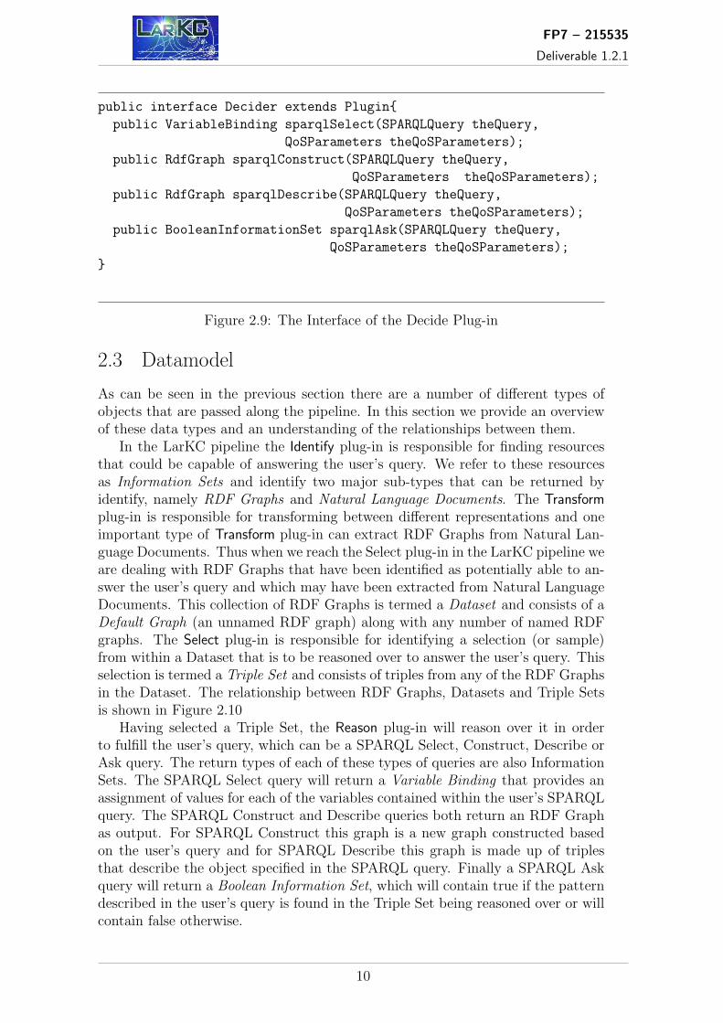
The Decide plug-in is responsible for building and maintaining the pipeline contain-ing the other plug-in types, and managing the control flow between these plug-ins.The interface of this plug-in can be seen in Figure 2.9.
The interface of the Decide plug-in is very similar to that of the reason plug-in(as LarKC is a platform for large scale reasoning and as such can be viewed as areasoner). The major difference is that actual data to reason over is not explicitlyspecified, at least not in the current version of the platform, as the Identify plug-inis responsible for finding the data within the pipeline.
4http://jena.sourceforge.net/
9
FP7 – 215535
Deliverable 1.2.1
public interface Decider extends Plugin{
public VariableBinding sparqlSelect(SPARQLQuery theQuery,
QoSParameters theQoSParameters);
public RdfGraph sparqlConstruct(SPARQLQuery theQuery,
QoSParameters theQoSParameters);
public RdfGraph sparqlDescribe(SPARQLQuery theQuery,
QoSParameters theQoSParameters);
public BooleanInformationSet sparqlAsk(SPARQLQuery theQuery,
QoSParameters theQoSParameters);
}
Figure 2.9: The Interface of the Decide Plug-in
2.3 Datamodel
As can be seen in the previous section there are a number of different types ofobjects that are passed along the pipeline. In this section we provide an overviewof these data types and an understanding of the relationships between them.
In the LarKC pipeline the Identify plug-in is responsible for finding resourcesthat could be capable of answering the user’s query. We refer to these resourcesas Information Sets and identify two major sub-types that can be returned byidentify, namely RDF Graphs and Natural Language Documents. The Transformplug-in is responsible for transforming between different representations and oneimportant type of Transform plug-in can extract RDF Graphs from Natural Lan-guage Documents. Thus when we reach the Select plug-in in the LarKC pipeline weare dealing with RDF Graphs that have been identified as potentially able to an-swer the user’s query and which may have been extracted from Natural LanguageDocuments. This collection of RDF Graphs is termed a Dataset and consists of aDefault Graph (an unnamed RDF graph) along with any number of named RDFgraphs. The Select plug-in is responsible for identifying a selection (or sample)from within a Dataset that is to be reasoned over to answer the user’s query. Thisselection is termed a Triple Set and consists of triples from any of the RDF Graphsin the Dataset. The relationship between RDF Graphs, Datasets and Triple Setsis shown in Figure 2.10
Having selected a Triple Set, the Reason plug-in will reason over it in orderto fulfill the user’s query, which can be a SPARQL Select, Construct, Describe orAsk query. The return types of each of these types of queries are also InformationSets. The SPARQL Select query will return a Variable Binding that provides anassignment of values for each of the variables contained within the user’s SPARQLquery. The SPARQL Construct and Describe queries both return an RDF Graphas output. For SPARQL Construct this graph is a new graph constructed basedon the user’s query and for SPARQL Describe this graph is made up of triplesthat describe the object specified in the SPARQL query. Finally a SPARQL Askquery will return a Boolean Information Set, which will contain true if the patterndescribed in the user’s query is found in the Triple Set being reasoned over or willcontain false otherwise.
10

FP7 – 215535
Deliverable 1.2.1
Figure 2.10: Elements of the LarKC Data Model
2.4 Example Scenario
The motivation for this storyboard comes from an attempt to try and understandwhat activities take place when a LarKC platform evaluates a query. It is notintended to try and identify which components will carry out particular tasks, noreven to identify what components will exist at all. Rather, the aim is to show asequence of activities.
Consider the SPARQL query shown in Figure 2.11 which expresses the sentence“Who knows Tim Berners-Lee?”:
PREFIX rdf: <http://www.w3.org/1999/02/22-rdf-syntax-ns#>
PREFIX foaf:<http://xmlns.com/foaf/0.1/>
SELECT ?name WHERE {
?person rdf:type foaf:Person .
?person foaf:name "Tim Berners-Lee" .
?person2 rdf:type foaf:Person .
?person2 foaf:knows ?person .
?person2 foaf:name ?name .
}
Figure 2.11: An example of a SPARQL query
In order to evaluate this query, the following steps must be completed:
1. The user passes the query to the LarKC platform.
2. A pipeline must be constructed from available components that pass thecorrect data-types between them.
11

FP7 – 215535
Deliverable 1.2.1
3. The query is examined to extract keywords - any identifier from the triplepatterns of the WHERE clause.
4. The keywords are passed to an Identify plug-in (a wrapper for www.sindice.com in this case).
5. The identify step returns URLs of RDF documents (or documents containingembedded RDF statements).
6. No data transformation is imagined for processing this query.
7. The URLs are passed to a select component that needs access to the triples,therefore it is here that the URLs must be ’dereferenced’ and RDF statementsdownloaded, and the selection component applies its selection strategy (inthis simple case returning all triples).
8. The triples are passed on to the reasoning component that executes theoriginal SPARQL query against this data set.
9. The results of the query are returned to the user.
The storyboard described above has been implemented in the first demo of theplatform, which can be tested at http://www.larkc.eu/baby-larkc.
12

FP7 – 215535
Deliverable 1.2.1
3 Use-case Scenarios
In this chapter, we take the description and requirement specification of the eachof use cases considered in LarKC (reported in deliverables D7b.1.1a, D7b.1.1band D6.1) and present one possible way of combining different LarKC plug-insin order to support the implementation of each of the scenarios. For the sake ofsimplicity we do not provide a detailed description of each use case. The interestedreader is referred to D6.1 (Urban Computing use case), D7b.1.1a (Early ClinicalDevelopment use case) and D7b.1.1b (Carcinogenesis Research use case).
3.1 Use Case WP6: Urban Computing
3.1.1 Getting to Milano
This story-board use-case, used as an example study LarKC platform configura-tion, expects LarKC to be used by a travel planning system, which will have accessto, and reason over, all of the city of Milan’s traffic, event and weather data. Inthis particular use-case, users do not query the platform directly, but use someadvisory system which calls LarKC as its reasoning engine and/or data retrievalservice.
The use of the Platform in this case is divided into two modes:
• Planning mode, which starts when the user asks for possible routes to adesired destination, and
• Informing mode, which comes into action when additional data that affectspreviously planned trips becomes available.
Planning mode: The purpose of this mode is to find one or more possiblenear-optimal ways to travel from the user’s current location to a destination whileobeying a set of constraints. Data is retrieved from a variety of sources, all ofwhich may return different types of results. This suggests a LarKC configurationrequirement of one data transformer plug-in for each data source. Also, becausethis travel planning problem has particular features, for example by virtue ofbeing, at base, a planning problem, an extended (non-default) implementation ofa decider plug-in may be needed.
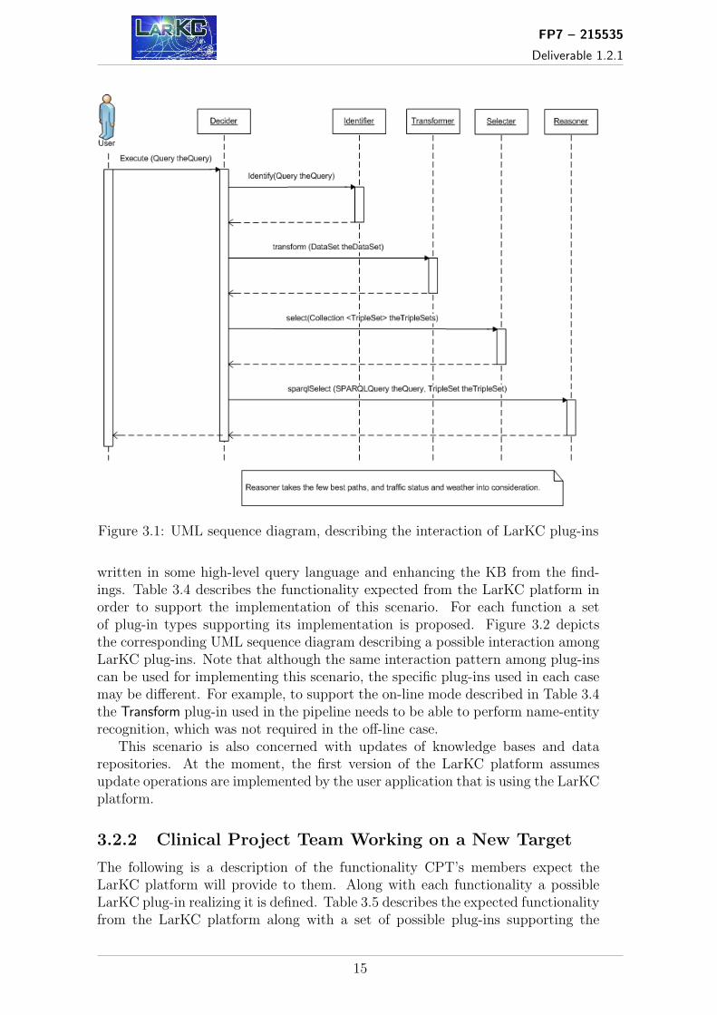
Table 3.1 shows the functionality expected from the LarKC platform in or-der to support planning. Figure 3.1 illustrates the corresponding UML diagram,describing the interactions among plug-ins.
Informing mode: The purpose of this mode is to monitor traffic status,and traffic-affecting events, and then find the planned routes that this new dataaffects. This task is easier in some respects than that of planning mode sinceonly two data sources (possible identifiers) are needed: one accessing data aboutcurrent planned routes, and one the traffic status data. The associated reasoning,though, is potentially quite complex, depending on the nature of the status data.
In the simplest implementation, this ”Informing mode reasoning” could amountto simply returning to planning mode with a new route query, to check whetherthere is more appropriate route under the new traffic/weather conditions. Moresophisticated plan transformation implementations are also possible.
13

FP7 – 215535
Deliverable 1.2.1
Support for Possible Plug-insRetrieve route planning data from several sources Identifier(e.g. Google maps, railroad companies, bus operators, etc.)Retrieve weather information IdentifierRetrieve parking information IdentifierRetrieve traffic information IdentifierIntegration of data DeciderPick the few best ways to reach the destination Reasoner
Table 3.1: Possible Plug-ins supporting the implementation of the planning sce-nario
Communication between plug-ins for simple ”informing” is similar to that inplanning mode (Figure 3.1), except that two different queries are issued. Table3.2 shows the functionality that is required from the LarKC platform in order tocomplete this reasoning task:
Support for Possible Plug-insRetrieve planned routes that are still valid IdentifierRetrieve traffic/weather conditions and status IdentifierSelect appropriate subset, i.e. Match data by locations SelecterDecide which routes are affected Reasoner
Table 3.2: Possible Plug-ins supporting the implementation of the planning sce-nario
3.2 Use Case WP7a: Early Clinical Drug Development
The Early Clinical Drug Development use case is divided into four scenarios or sub-cases. In the following we describe the requirements that each of these scenariosimpose on the LarKC platform and provide a possible configuration of plug-ins inorder to support the implementation of applications in each of the scenarios.
3.2.1 Improve Knowledge About Disease and Patients
This scenario is divided in two operation modes: off-line and on-line or interactivemode.
Off-line mode: The purpose is to find and process new additional informa-tion from text documents and ontologies. This constitutes the base process to keepthe repository updated. Table 3.3 describes the functionality epidemiologists ex-pect/require from an application supporting this scenario. Additionally, the tableshows a set of possible LarKC plug-ins that can be used for implementing the re-quired functionality. Figure 3.2 depicts the corresponding UML sequence diagramdescribing a possible interaction among LarKC plug-ins in order to implement thescenario.
On-line mode: This scenario is concerned with finding and processing newadditional information, exploring hypothesis through the formulation of queries
14
FP7 – 215535
Deliverable 1.2.1
Figure 3.1: UML sequence diagram, describing the interaction of LarKC plug-ins
written in some high-level query language and enhancing the KB from the find-ings. Table 3.4 describes the functionality expected from the LarKC platform inorder to support the implementation of this scenario. For each function a setof plug-in types supporting its implementation is proposed. Figure 3.2 depictsthe corresponding UML sequence diagram describing a possible interaction amongLarKC plug-ins. Note that although the same interaction pattern among plug-inscan be used for implementing this scenario, the specific plug-ins used in each casemay be different. For example, to support the on-line mode described in Table 3.4the Transform plug-in used in the pipeline needs to be able to perform name-entityrecognition, which was not required in the off-line case.
This scenario is also concerned with updates of knowledge bases and datarepositories. At the moment, the first version of the LarKC platform assumesupdate operations are implemented by the user application that is using the LarKCplatform.
3.2.2 Clinical Project Team Working on a New Target
The following is a description of the functionality CPT’s members expect theLarKC platform will provide to them. Along with each functionality a possibleLarKC plug-in realizing it is defined. Table 3.5 describes the expected functionalityfrom the LarKC platform along with a set of possible plug-ins supporting the
15

FP7 – 215535
Deliverable 1.2.1
Support for Possible Plug-insRetrieve (semi)structured data from different sources IdentifierTransformation of the retrieved data into RDF TransformerIntegration of data sources TransformerURI mappings Reasoner or DeciderSelect appropriate subsets of KB to work with SelecterReduce redundancy with relation interpretation ReasonerNavigate structured information exploring Deciderrelations and data sources
Table 3.3: Possible Plug-ins supporting the implementation of the off-line scenario
Figure 3.2: UML sequence diagram describing a possible interaction of plug-ins toimplement the use case
implementation of the scenario. The same plug-in interaction pattern depicted inFigure 3.2 can be used for implementing this scenario. Once again, the specificplug-ins used will vary depending on the requirements stated in Table 3.5.
3.2.3 Identifying Biomarkers and Target Mechanisms
Table 3.6 describes the functionality users (from the Bioscientist’s point of view)expect the LarKC platform will provide to them in order to be able to implementthis scenario. Along with each functionality a possible set of LarKC plug-inssupporting the scenario is proposed. The same plug-in interaction pattern depictedin Figure 3.2 can be used for implementing this scenario. However, notice that thespecific plug-ins used will vary depending on the requirements stated in Table 3.6.
16

FP7 – 215535
Deliverable 1.2.1
Support for Possible Plug-insRetrieve unstructured document IdentifierTransformation of the retrieved data into RDF TransformerApply name-entity recognition Decider or TransformerApply semantic annotations to the ontology instances Deciderand relation extractionSelect appropriate subsets of KB to work with SelecterConsistency checking of extracted relations against Deciderknowledge from structured data sourcesSpecify queries to be evaluated against the Decider(un)structured data, and explore different entities andtheir co-occurrence
Table 3.4: Possible Plug-ins supporting the implementation of the on-line scenario
Support for Possible Plug-insReuse knowledge generated by the previous scenario User applicationand extend it with results fromEpidemiologist’s reportsIdentify the mechanisms of already conducted clinical IdentifiertrialsFilter available sources SelecterUse facet-based search interface supporting different Decider, Reasonersearch criteria and covering both public and in-housedata sources (by applying resource classificationalgorithms)Processing of queries written in natural language Reasoner, Transformer
Table 3.5: Possible Plug-ins supporting the implementation of the scenario ‘Clin-ical Project Team Working on a New Target’
3.2.4 Signal Evaluation of Adverse Drug Event Reports
Table 3.7 shows a description of the functionality users (from the Safety Expert’spoint of view) expect the LarKC platform will provide to them. Along with eachfunctionality a possible LarKC plug-in realizing it is defined. The same plug-ininteraction pattern depicted in Figure 3.2 can be used for implementing this sce-nario. However, the specific plug-ins used will vary depending on the requirementsstated in Table 3.7.
3.3 Use Case WP7b: Carcinogenesis Research
The Carcinogenesis Research use case is divided in two scenarios. The first oneis concerned with assisting scientists in the production of reference works (Mono-graph Production scenario) while the second one is concerned with assisting epi-demiologists in the analysis of gene-disease association study data (the GenomeWide Association Studies scenario).
17

FP7 – 215535
Deliverable 1.2.1
Support for Possible Plug-insImport data from laboratory results IdentifierTransform the imported data to RDF TransformerIdentify proteins and map them to public data sets Identifier, DeciderFilter/remove available sources SelecterInterpret the semantics of the relations and annotate results User applicationTest hypothesis User application
Table 3.6: Possible Plug-ins supporting the implementation of the scenario ‘Iden-tifying Biomarkers and Target Mechanisms’
Support for Possible Plug-insCollect all relevant resources IdentifierApply name-entity recognition Decider, TransformerFilter available sources, select most relevant one SelecterInfer relation of different adverse events ReasonerInterpret the semantics of the relations and annotate User applicationresultsUser-friendly interface to explore the full information User applicationsources generated in previous sub cases
Table 3.7: Possible Plug-ins supporting the implementation of the scenario ‘SignalEvaluation of Adverse Drug Event Reports’
3.3.1 Monograph Production
This scenario is divided in two operation modes: off-line and user-interaction mode.Off-line mode: The purpose of the off-line mode is to assist users in finding
and processing the data (both texts and ontologies) required to answer user queries.Table 3.8 provides a summary of the tasks comprising this scenario. In the table,LLD refers to Linked Life Data, a platform to enable semantic data integration inearly clinical and drug development process. Each of these tasks in turn imposesrequirements to the LarKC platform in terms of the expected functionality. Thetasks carried out in the off-line mode are the same as those carried out in the off-linemode of the Genome Wide Association Studies scenario. Table 3.8 also shows a setof possible LarKC plug-ins that can be used for supporting the scenario. The sameplug-in interaction pattern depicted in Figure 3.2 can be used for implementingthis scenario. However, the specific plug-ins used will vary depending on therequirements stated in Table 3.8.
Support for Possible Plug-insRetrieve data for LLD Identifier, SelecterTransform to appropriate representations TransformerIntegrate related LLD sources ReasonerRetrieve texts Identify, SelecterAnnotate texts using LLD User application
Table 3.8: Possible Plug-ins supporting the implementation of the off-line scenario
18

FP7 – 215535
Deliverable 1.2.1
User-interaction mode: In the user-interaction mode users interact withan application by formulating queries using some high-level query language. Theapplication uses the services provided by the LarKC platform to answer the queriesand present the results to the end user. Table 3.9 provides a summary of the taskscomprising this scenario. The table also shows a set of possible LarKC plug-insthat can be used for supporting the scenario.
Support for Possible Plug-insRetrieve triples matching the query ReasonerPresent associated information: author networks, User application, Reasonerconceptual links etc.Navigate to related triples and texts User application, Reasoner
Table 3.9: Possible Plug-ins supporting the implementation of the user-interactionscenario
3.3.2 Genome Wide Association Studies
As with the previous scenario, this scenario is divided in two operation modes:off-line mode, which is handled as in the previous scenario and, a scripted mode.The off-line mode is similar to the off-line mode in the monograph productionscenario described before.
Scripted mode: Table 3.10 provides a summary of the tasks comprising thisscenario as well as a set of possible LarKC plug-ins that can be used for supportingthe scenario.
Support for Possible Plug-insQuery generation and expansion DeciderKnowledge base querying DeciderPaper retrieval and search Identify, Select
Table 3.10: Possible Plug-ins supporting the implementation of the scripted mode
19

FP7 – 215535
Deliverable 1.2.1
4 Issues Concerning Remote Invocation
One of the options for the deployment of LarKC is to consider a distributed ar-chitecture, where platform and different plug-ins are located at remote locationsfrom each other. This distributed architecture has some implications affectingthe design of the different components, such as trust and security, data transfer,etc. In the following sections we identify and analyze the remote issues affectingthe LarKC framework. This is a preliminary analysis and some initial thoughtsabout the potential implications of this distributed architecture. Some hints aregiven on current standards and specifications that could solve the identified issues.Currently an architectural discussion is ongoing as part of WP1 and WP5 andtherefore, the suggestions in this document must be taken as so, and not as finalarchitectural decisions for the LarKC Framework.
4.1 Trust and Security
The aim of this section is to identify the trust and security related issues that theLarKC framework needs to address when it is deployed following a distributed ar-chitecture. In the following subsections, different phases of the LarKC frameworkdeployment and execution are analyzed from the trust and security viewpoint.There are different standards to manage the security in a distributed environ-ment. One of the standardization groups dealing with security is the WSS (WebServices Security) Technical Committee in OASIS 1, which includes specificationsfor different security related aspects, such as SOAP Message Securtiy, X.509 cer-tificates, SAML Token Profile among other specifications.
Registration of external plug-ins
In the case where the LarKC plug-ins are located in remote sites with respectto the LarKC platform, there must be a process of registration or announcementthat the plug-in is available and under which conditions. One of the essential re-quirements is the compatibility between the a plug-in interface and the platforminterface. But besides interface compatibility, it must be ensured that the remoteplug-in is a trusted entity of the platform. Therefore, it becomes necessary to setupa trust and security framework in order to ensure the authentication of externalplug-ins and authorization by the LarKC platform.
Execution of a plug-in in a distributed environment
In the cases when the plug-in algorithm can be parallelized, one of the possi-bilities to increase the performance of its execution is to run it over distributedresources, in a thinking@home fashion. In this case, it must be ensured that thedistributed resources are trusted entities to the platform, or to the central entitythat manage the execution of plug-ins. The distributed execution of plug-ins is asubject that raises questions in several aspects such as confidentiality of data andconfidentiality of connections between distributed resources. These issues will be
1http://www.oasis-open.org/committees/wss
20

FP7 – 215535
Deliverable 1.2.1
further analyzed in future LarKC deliverables. Ideas from similar projects can betaken into account. For example the BOINC project 2 may provide some interest-ing ideas regarding security issues.
Execution of plug-ins in a cluster environment
In the case when a certain plug-in is designed to be executed within a cluster en-vironment (for efficiency or other reasons, in the case of parallelizable algorithms)trust and security issues must be considered for the communication between thecluster and the LarKC components located outside the cluster (the LarKC plat-form, other LarKC plug-ins, external data storage). The way we think to usethe cluster environment is basically that a plug-in (we will call cluster-plug-in)is deployed there and is executed from outside, triggered by the LarKC platform(control flow). Data (or references to that data) is transmitted from external plug-ins or from the platform to the cluster-plug-in and viceversa. Therefore we mustconsider security issues in all these phases of the cluster-plug-ins life cycle:
• Deployment of the plug-in inside the cluster.
• Data (or reference to data) flow between the cluster plug-in and externalplug-ins or data storage components, data (or reference to data) flow betweenthe cluster plug-in and the LarKC platform (considering bi-directional flowin both cases).
• Control-flow between the cluster plug-in and the LarKC platform(bi-directional).
The external components must have the necessary rights to access the clusterand must be trustable to be accessed by the cluster. To ensure a secure commu-nication, the connection to the cluster is restricted by a firewall which requires alogin of the user (in our case, an external plug-in or the LarKC platform). Anidentification of the external user is mandatory. In the same way, every compo-nent outside the cluster that need to be accessed by the cluster-plug-in has to bea trusted entity for the cluster. Therefore, all components interacting with thecluster must be authorized against it. Figure 4.1 depicts this scenario.
A cluster (inside the square) consists of the worker nodes (compute nodes) plusa head node. Login from the outer world is only possible through the head node,never to the worker nodes. In some computing centers the queuing system is alsorun on the head node. In the picture above, the queuing system is located in aseparate machine, behind another firewall.
Another additional possibility to ensure the required security from the clusterviewpoint is to build temporary storage nodes inside the barriers of the cluster.If such storage nodes are inside the Cluster security issues such as authenticationand registration for external users through the firewall are not necessary. Whenthe process is finalized the stored data are removed from the Cluster. In generalwe determine that it is mandatory to have user authentication/authorization (e.g.registration, password, trusted IP) which permits a human user, a plug-in or the
2http://boinc.berkeley.edu/
21

FP7 – 215535
Deliverable 1.2.1
Figure 4.1: Access to a Cluster environment
LarKC platform itself to access the cluster and which allows a secure data or con-trol flow transfer.
Secure communication between distributed plug-ins
In this section we must consider which flows are transmitted between plug-insand how. According to the latest discussions within WP5, we can distinguishbetween two different kind of flows: data and control. All control flows mustgo through the Decider plug-in and only data (or references to data) flows aretransmitted directly between the rest of plug-ins.
When two plug-ins communicate with each other it has to be ensured thatboth parties are trustable. In this sense, it has to be defined how authenticationis performed between them. The proposed solution is that the authentication taskmust be done in the registration phase, that is, when the plug-in is registered inthe LarKC platform. We will then assume that all plug-ins registered within acertain instance of the LarKC platform have been already authorized to belongto the LarKC framework and are therefore a trusted party. This means that allparties which are involved in the communication process are who they claim to be.Furthermore, besides authentication, authorization has to be ensured as well. Forthe authorization a mechanism is needed that decides when a user is authorizedto perform a certain task and when not.
22

FP7 – 215535
Deliverable 1.2.1
Authorization and authentication are closely related to each other because ifa certain party is authorized for a certain task it is essential that the party is theone he claims to be he is. Security in the data transmitted must be also ensured.We must determine then in which parts of the transmission path the security maybe affected (e.g. when the communication is performed through public links, likethe Internet). In this cases, the level of confidentiality or privacy required for theconcrete data will be the key to determine the level of security to be applied to thecommunication path (solutions such as data encryption can be adopted). Besidesconfidentiality, integrity of the data must be also ensured. This means that thereceiving end must be able to know for sure that the received message is exactlythe one that the transmitting end has sent to him.
Furthermore, the privacy of a communication has to be considered. A com-munication has to be private in the way that only the sender and the receivershould be able to understand the conversation. Through privacy a third partywhich might eavesdrop the conversation is not able to make any sense out of thecommunication massage.
4.2 Plug-in registration and discovery
The LarKC platform must allow the registration of new plug-ins located at remotesites. In this case there must be a process of registration or announcement that theplug-in is available and under which conditions. Furthermore, to be more flexiblethe platform should support registration of plug-ins at runtime. How this can beachieved in the LarKC platform is still an open issue that will be analyzed in moredetails in future deliverables.
One of the essential requirements for the registration of plug-ins is to be ableto describe not only the functional aspect of plug-ins but also their non-functionalaspect. This description will also allow the platform to discover plug-ins based ondifferent properties. Such description of plug-ins will be expressed expressed inwhat we call “the plug-in description language”. Within the plug-in descriptionthere must be information such as type of plug-in, functional parameters, QoSparameters, information regarding contract and context of the execution. Theconcrete definition of the plug-in description is a work in progress within WP1and WP5 and it will be part of future deliverables of the LarKC project.
As mentioned before, once the plug-ins register in the platform (or express insome way their availability to the platform), a mechanism to find the available plug-ins must be defined. The location of resources in large scale heterogeneous networksis a complex task. To handle this, some kind of Service Discovery mechanism isneeded.
One widely accepted service discovery mechanism among the web services com-munity is UDDI 3. UDDI is closely related to SOA and it is used as a standardizedregistry service for Web Services which is sponsored by OASIS. UDDI ensures thepublication of service listing and discovers each other service listings and defines inwhich way the services interact over the Internet. It is an open industry initiative
3http://www.oasis-open.org/committees/uddi-spec/doc/tcspecs.htm
23

FP7 – 215535
Deliverable 1.2.1
and it contains SOAP-interfaces.There are three approaches available in UDDIhow the service discovery takes place [1] 4:
1. White Pages Approach: The White Pages Approach includes basic in-formation similar to a phone book. Information about the identity of theService Provider are supported such as business area, contact details, con-tact person and a unique company classification number which is a D-U-N-Snumber.
2. Yellow Pages Approach: The Yellow Pages Approach orders the WebServices for a specific purpose. This approach is related to the idea of abusiness directory.
3. Green Pages Approach: The Green Pages Approach provides technicalinformation about the services which are exposed by the business. The de-scriptions of the interfaces of the Web Services are used to handle the services.This seems to be the most appropriate approach to handle LarKC plug-ins.
When we think of the LarKC plug-ins modeled as Web services, UDDI mightbe a useful solution for managing the discovery of plug-ins by the Decider plug-in(“meta-reasoner” of the platform). It is possible to store the services (in this casethe LarKC plug-ins) in a UDDI Registry. In the case of LarKC the Decider plug-inwill be able to find the required plug-in by contacting the UDDI Registry.
4.3 Heterogeneity
As part of the LarKC concept, external plug-in developers should be able to plugtheir own plug-ins and integrate them together with other developers’ plug-ins.Therefore, it would be interesting to ensure that the plug-ins and platform in-terfaces are independent of implementation language and execution platform, inorder to ensure the compatibility of heterogeneous components, implemented indifferent programming languages and running on different platforms.
The Web services approach to model the plug-ins seems to be and optimal andvery convenient solution to cope with this issue. The use of a description languagesuch as WSDL to describe the plug-ins as Web services allows the integrationand interoperability of heterogeneous services, making the LarKC architectureindependent from any specific implementation language or running platform ofthat service. However, the Web service technology stack has its disadvantagestoo and in particular, it may not be well suited for the high-speed, high-volumemessage passing that might be needed in some of the LarKC use-cases. Therefore,current discussions are focused on whether it is necessary to go beyond WSDL forthe description of plug-ins and add some domain specific language to describe plug-ins and their properties. Future deliverables in the LarKC project will considerthis issue in more details.
4http://www.irmosproject.eu/Deliverables/Default.aspx
24

FP7 – 215535
Deliverable 1.2.1
4.4 Data Transfer between remote components
At the time of writing this report, two different types of flows are being consideredbetween remote components:
• Data flow: directly between plug-ins.
• Control flow: between the Decider plug-ins and the rest of plug-ins.
It will be avoided, as far as possible, to transmit big amounts of data betweenplug-ins, for which we are applying the policy of ”lazy de-referencing”, consistingon passing references to the data sources as long as it is possible.
If we consider a distributed web services architecture, a possible solution tomanage data is OGSA-DAI 5. OGSA-DAI is a middleware product that allows dataresources, such as relational or XML databases, to be accessed via web services.
Some of the the main motivations for the development of OGSA-DAI are:
• To allow different types of data resources such as relational databases, XMLrepositories and files to be accessed from Grids.
• To provide a way of querying, updating, transforming and delivering datavia Web services.
• To provide consistent and data-independent access to data sources as wellas metadata.
• To support data integration from various data resources.
• To enable composition of Web services to provide higher-level Web servicesthat support data federation and distributed query processing.
A protocol for data transfer, compatible with the OGSA-DAI approach isGridFTP. It is used in the area of Distributed Computing. It is an extensionof the FTP (File Transfer Protocol) standard which ensures the use of FTP in aDistributed environment. It is supported by the Open Grid Forum (OGF) 6.
The aim of GridFTP is to guarantee a speedy data transfer of very largeamounts of data. Regarding to a Grid/Distributed environment the transfer oflarge data amounts is, of course, often a necessity. Therefore, GridFTP is an ad-equate solution for data transfer, especially when thinking about reliability andexecuting time of transfer. Furthermore, GridFTP bridges the gap between datastorage and accessing a system by defining a protocol for data transfer. Beyondthat GridFTP provides security aspects through in-built security. GridFTP en-hances FTP by aspects such as security with GSI, third party transfers, parallel andstriped transfer, partial file transfer, fault tolerance, automatic restart of transfersand automatic TCP optimization.
5http://www.ogsadai.org.uk/about/ogsa-dai/6http://www.ogf.org/
25

FP7 – 215535
Deliverable 1.2.1
4.5 Synchronization and communication between parallel
tasks
Different parallelization approaches are being considered for LarKC:
• Parallelization between plug-ins.
• Parallelization inside the plug-ins.
In both cases, we have to consider a way to communicate and synchronizebetween the parallel tasks that may be dependent on each other.
There may be a task which might depend on other tasks processed at same time.MPI is a de facto standard for the exchange of messages for parallel processingon distributed systems which is supported by the MPI-Forum 7.The goals of MPIare high performance, scalability and portability. In general an MPI applicationconsists of several processes which are communicating with each other. All ofthese processes are started in parallel at the same time. The processes are workingtogether on one task and they are exchanging messages with each other. Theadvantage of MPI is that the message exchange can take place among severalcomputers.
7http://www.mpi-forum.org/
26

FP7 – 215535
Deliverable 1.2.1
5 Support for Anytime Behaviour
In this section we discuss a number of programming models that could be used byLarKC to achieve anytime behaviour. As such, it will first try to define anytimebehaviour and then present a set of potential design solutions (programming mod-els). Each solution will have its own advantages and disadvantages. Through thisdiscussion, it is hoped that the consortium will choose the approach most suitablefor LarKC and this model will become the de facto standard that all writers ofsoftware components must adhere to.
In essence, LarKC hopes to achieve fast search/reasoning by using a combina-tion of:
• Approximate techniques.
• Novel techniques (borrowed from other disciplines), and
• Parallel execution.
Parallel execution involves the simultaneous execution of more than one ex-ecution context, or thread. For a single (hardware) processor system, this cansometimes allow for a simpler and more efficient design. However, it is on multi-processor systems that software designed for parallel execution can expect toachieve its scalability goals, i.e. more processors implies faster execution or moredata processed. In the context of LarKC and a multi-processor (and thereforea multi-threaded) environment, it naturally follows that a desired behaviour ofa LarKC platform would be that the ’user’ could terminate a search/reasoningtask at anytime and still have some meaningful answer (or set of results). Sucha behaviour is called anytime. The principal advantage, is that it allows the userto decide how best to trade response times with accuracy/quantity of results.Further, the LarKC platform is constructed from many components that worktogether (under the guidance of a Decide component) to deliver results to theuser. These components will in turn need to communicate and will likely also pass’intermediate results’ between themselves.
In order to support anytime behaviour among plug-ins and also between theplatform and the user, the API introduced in section 2.2 are defined in such away that the communication of streams of data among components is possible.More concretely, for every plug-in type that naturally produces something of typeX, the interface defines that the plug-in actually produces a stream of X’s. Themaximum size of the stream is given by the contract parameter. For example,the Select plug-in has as contract parameter the number of triples to be returned.When called, it starts producing a stream of triples up to the size of the contractparameter. This combination of contract parameter and streaming output givesthe consumer a good control over how many data are being maximally produced,in a single call. The consumer can choose between many calls with a small contractparameter (each producing short streams), or a single call with a large contractparameter, producing a single large stream. Of course, a particular design mustbe chosen to implement such non-blocking streaming output.
In the following sections we discuss different design alternatives aimed at sup-porting anytime behaviour in LarKC. We first consider the case of anytime be-haviour that exists at the boundary of LarKC, i.e. between the user and platform.
27

FP7 – 215535
Deliverable 1.2.1
It may well be that one solution fits all, so that we can use a single anytime modelthroughout LarKC as a whole. However, after considering the user-LarKC inter-face, the section will be further expanded with an analysis of the communicationrequirements between LarKC components.
5.1 Interface between LarKC and User
The interface between the LarKC platform and the users should be defined withthe following design goals in mind:
• The LarKC interface should be as simple as possible to give the user maxi-mum flexibility to integrate with LarKC.
• The user should not be forced to use unacceptably complex synchronisationmechanisms (preferably none at all).
• The user thread should not block indefinitely when making a request to aLarKC platform.
5.1.1 Callback
In some ways, this is the simplest model of all. The basic idea is similar to the oneimplemented by the Observer design pattern, i.e. to get notifications of events,one must create a class that supports a particular Observer interface and pass aninstance of this class to the “thing” doing the notification. Figure 5.1 shows theUML class diagram that models a callback scenario.
The sequence of events in the LarKC case would be as follows (the correspond-ing UML sequence diagram is depicted in Figure 5.2):
1. User creates an object to receive asynchronous results (a receiver).
2. User passes this receiver object with a request (SPARQL query) to LarKC(and returns immediately).
3. LarKC does some processing and starts to return results by calling methodson the receiver object (LarKC thread, not user thread).
4. The receiving object does whatever it needs with the results.
Advantages of the Callback-based Method
• Very simple model.
• Well understood and similar to existing java paradigms (although swing issingle-threaded).
• User thread is at no time blocked in LarKC components (either waiting fora LarKC response or polling an object for a response).
• User has complete control over synchronisation mechanism used.
Disadvantages of the Callback-based Method
28

FP7 – 215535
Deliverable 1.2.1
Figure 5.1: The UML Class Diagram that models the callback scenario
Figure 5.2: Sequence of events for the callback scenario
29

FP7 – 215535
Deliverable 1.2.1
Figure 5.3: The UML Class Diagram that models the Queue-based scenario
• LarKC callback thread executes user code (potentially blocking for unac-ceptable time).
• The user is required to implement all synchronisation mechanisms when pro-cessing results.
• Terminating a search/reasoning task early requires some mechanism to “de-register” the receiver object (with possibly complicated synchronisation is-sues).
• Results are returned one-at-a-time, although there is the possibility for batchresults, i.e. passing many results in one call to resultEvent().
5.1.2 Queue
A common technique for passing messages between communicating threads is touse some form of synchronised queue. In this model, a queue exists at the boundarybetween the components (or the system and a user). As messages are generatedby one component, they are put on to the queue for the target component. When-ever the target component thread is available for processing messages, it “takes”messages from its dedicated queue. Figure 5.3 shows the UML class diagram thatmodels a callback scenario.
All synchronisation in this model is handled by the queue itself. The queuemanages contention between threads putting and taking from the queue simul-taneously. Also, attempting to take from an empty queue can either block untilthere is something in the queue (take) or return immediately if the queue is empty(poll).
For LarKC, the messages passed between the platform and the user will bequery results. The sequence of events would roughly be like this (the correspondingUML sequence diagram is depicted in Figure 5.4):
1. User submits a query to the platform - this call returns immediately witha (handle or reference to a) result queue (or this could be provided by theuser).
30

FP7 – 215535
Deliverable 1.2.1
2. The platform starts putting results in to the queue as they are generatedand continues until there are no more results or it is told to stop.
3. User enters a loop removing from the queue until there are enough resultsor there are no more results.
Figure 5.4: Sequence of events for the Queue-based scenario
Advantages of the Queue-based method
• Very simple model.
• Very loose coupling between components.
• LarKC thread executes only LarKC code and user thread executes only usercode.
• No explicit synchronisation mechanisms are required - all handled by thequeue.
• User code can be essentially single threaded.
• Suitable standard queue implementations already exist (java.util.concurrent).
Disadvantages of the Queue-based method
• Care must be taken to avoid queue explosion - when the user processes resultsslower than LarKC generates them (can be avoided with a bounded queue,but with the possibility of losing results).
• User thread must either block on the queue when there are no results, orpoll the queue in a loop.
31

FP7 – 215535
Deliverable 1.2.1
6 Storage/Data Layer of the Platform
In the context of software engineering a data layer is responsible for automatingthe persistence of the system and user information. Thus, an important require-ment is the efficient storage and access to data and the related meta-data. Theknowledge representation formalism to be adopted by LarKC, which will be re-ported in Deliverable D1.1.3, uses an extended RDF-based data model with flexiblesupport for named graphs and triplesets. To summarize the rationale behind thisbackward-compatible extension of the named graphs we can consider a scenariowhere plug-ins can share large volumes of data, ‘passing’ this data from one toanother via a shared data layer. Technically, one plug-in can pass a reference toa tripleset (part of the data in a dataset stored in a shared repository), which issubject to processing at the next step of the pipeline.
The major functionalities of the data layer can be summarized as follows:
1. Persistence and retrieval of data through a standard API, optimized to dealwith huge volume of information (e.g., streaming support);
2. import from (parsing) and export to (serialization) standards formats (e.g.all the popular RDF syntaxes);
3. standard query mechanism and infrastructure (e.g., SPARQL endpoint);
4. sharing reasoning-related metadata (e.g. attaching weights, timestamps orother system information to RDF statements). This meta-data will be ac-cessible only through the storage and retrieval API;
5. possibility to support light-weight reasoning.
Being isolated through a relatively simple API, the data layer allows differentmodalities of data storage and interchange:
1. Data sharing among multiple plug-ins;
2. local storage, specific to the plug-in;
3. download of an RDF graph from remote host and making it locally accessiblethrough the standard API;
4. providing access to RDF data, stored as local file in a standard syntax.
A Shared/remote repository can reduce communication and computation costsas many reasoning tasks can be reduced to query evaluation. Communication isoptimized because the volume of the query results is usually much lower than thevolume of data involved in (transferred for) the evaluation. Moreover, a repositorycomponent can be distributed or parallelized under a variety of different schemata,while this remains transparent to the platform and the plug-ins. This way the datalayer allows for “separation of concerns” (the storage master takes care of storageoptimization, decides on distribution strategy, etc.)
The data layer’s API is based on the ORDI 1 data model’s API and supportsthe following six formal operations:
1http://www.ontotext.com/ordi/
32

FP7 – 215535
Deliverable 1.2.1
• Adding a new statement: The operation adds a new statement to themodel.
• Removal of a statement: This operation retracts a fact from the modelincluding all associations to triplesets. Compared to the named graph modelit has a well defined semantics, i.e. if two triples in different named graphsexist only one will be retracted.
• Assign a statement to a tripleset: The operation associates a triple froma named graph to a tripleset. If the statement does not exist the statementis not asserted.
• Un-assign a statement from a tripleset: This operation removes theassociation statement from a tripleset, however it leaves the statement inthe named graph. If the statement does not exist or it is not associated withthe specified tripleset, the operation causes no changes to the model.
• Retrieval of statements: This operation retrieves a set of statements andtheir triplesets based on simple pattern match.
The complete Java-based implementation and documentation of the ORDIdata model’s API could be found at: http://ordi.sourceforge.net/apidocs/
index.html
33

FP7 – 215535
Deliverable 1.2.1
7 Prototype implementation: Baby-LarKC
The design outlined above has been implemented in two test-rigs in order to vali-date the general LarKC ideas. These will be briefly described here.
7.1 Scripted DECIDE Plug-in
This test-implementation is available at http://www.larkc.eu/baby-larkc. Thisimplements a simple LarKC pipeline. The functionality of this pipeline is to actas a SPARQL endpoint to RDF triples available anywhere on the Semantic Web.The pipeline consists of the following plug-ins:
• QueryTransformer: It takes the user-input SPARQL query and transformsit into a number of triple-patterns that summarizes the query patterns thatmake up the users’ initial query.
• Identify: The triple-pattern queries that have been created are being usedto invoke Sindice, which returns URI’s at which triples conforming to thesepatterns can be found. The contract parameter of the Identify plug-in deter-mines how many of these URI’s should be returned (streaming fashion).
• Select: The current Select plug-in only displays two very simple behaviors,either select all or select only the first URL.
• Reason: The Reason plug-in dereferences the triples to be found at theremote URLs, loads them into a local Jena store and executes the originaluser SPARQL-query on them.
• Decide: These plug-ins are under the control of a simple scripted Decideplug-in that executes these plug-ins in the above fixed order, iterating theIdentify plug-in with a small value for the contract parameter.
Because of the contract-parameter on the Identify plug-in, this pipeline yieldsan increasing stream of answers to the original query, as increasingly more URIsare returned by Sindice.
7.2 Self-configuring DECIDE Plug-in
A second version of the above scenario has been implemented but this time witha more intelligent Decide plug-in. Using the Cyc platform, each of the plug-ins(QueryTransformer, Identify, Select, Reason), as well as a number of other plug-ins(e.g. multiple QueryTransformer) register themselves by adding statements in ameta-knowledge-base, stating facts about their type (Identify, Select, etc.) andtheir I/O signature. Using these signatures, the Decide plug-in decides whichpotential pipelines can be configured with these plug-ins, then chooses one, andsubsequently executes it.
34

FP7 – 215535
Deliverable 1.2.1
7.3 Discussion
In this section we discuss some of the important aspects of Baby-LarKC.
7.3.1 Remote Execution
The Identify plug-in is written as a stub-plug-in which itself makes remote callsto Sindice (currently running in DERI Galway, Ireland). Writing such stubs isa quick way to obtain remote execution of plug-ins. We intend to write skeletonsoftware to enable parties outside the consortium to make their web-accessibleplug-ins available as LarKC plug-ins.
7.3.2 Same code between the two test-rigs
The two test-rigs only differed in their code for the Decider, and in some minimalwrapping code for each plug-in to register the required information about itself inthe meta-knowledge-base. All the other code is exactly the same between the twotest-rigs, giving us confidence that indeed plug-ins will be re-usable under differentDecide plug-ins.
7.3.3 Limited scalability because of data transfer
Obviously the Baby-LarKC pipeline is not massively scalable since it relies onphysically loading the selected remote triples into a local Jena store in order toexecute the query. This physical transfer is the main bottleneck of this systemand the reason why we refer to it as a ”Baby” implementation of LarKC. Aninteresting alternative plug-in would execute the SPARQL query remotely at eachof the data-stores that Sindice identifies, or at least do so for all of the data-storesthat are available as SPARQL endpoints.
35
FP7 – 215535
Deliverable 1.2.1
8 Concluding Remarks
In this document we have described the initial operational framework aimed atsupporting the development of applications that require massive distributed in-complete reasoning at Web-scale. We presented an overview description of thefirst version of the LarKC platform in terms of its components (plug-ins) and thefunctionality provided by the platform. Plug-ins were defined in terms of theirinterfaces and behaviour. We discussed the three usage phases of the platformand described how the platform supports user interaction. We also introducedand described the datamodel used in the platform.
The description of the platform was complemented by a study of the three usecases considered in the project. This analysis was aimed at identifying the requiredfunctionality to be provided by the platform in order to support the implementa-tion of applications in each scenario. Moreover, the analysis served as an input tothe definition of the various plug-in types that constitute the architecture.
This document also reported on some important issues related to the designand implementation of the LarKC platform. In particular, we reported on theongoing discussions in WP1 and WP5 concerning a various architectural aspectssuch as remote invocation of components, trust and security, data storage and,support for anytime behaviour. Finally, we described a prototype implementationof the current LarKC architecture that implements the design decisions discussedin this document.
The work reported in this document constitutes the first step towards thedesign of the LarKC platform and therefore many issues still remain open. Onesuch issue is the specification of Quality of Service for the platform and its plug-ins.The definition of the various plug-in types presented in this document was purelyconcerned with their functional aspect, i.e. the description of the functionalityprovided by each of them in terms of their input/output. Since LarKC is alsoabout managing resources to achieve approximate and/or anytime behaviour, theinterfaces of the different plug-in types (both between platform and plug-ins andbetween plug-ins) must also capture QoS aspects. In this respect, an analysis of thedifferent use cases considered in LarKC would be the starting point for providinga non-functional description of the platform and its plug-ins. The result of thisanalysis will be a vocabulary of QoS parameters for each plug-in type as well asa series of configuration parameters used for “customizing” the execution of theplatform according to the use cases’ needs. Also, related to the specification of QoSis the choice of an appropriate formalism for the specification of these parameters.This as well as other design issues will be addressed in details in future deliverablesof the project.
36

FP7 – 215535
Deliverable 1.2.1
References
[1] IRMOS Consortium. The irmos project: D2.3.1 state of the art irmos tech-nologies. Technical report, 2008.
37