
FOX-10 / FOX-20 Basic-Module - TRS...
20
FOX-10 / FOX-20 Basic-Module Technical Documentation Sub-Modules for FOX-10 / FOX-20 MDI 8 8 digital inputs, 24 VDC MDO 8 8 digital outputs, 24 VDC/0.5A MDR 8 8 relay outputs MAC 8 8 digital AC inputs, 110 VAC/220 VAC MDM 8 8 digital DMOS outputs, 24 VDC/2.0A MAI 4 4 analog inputs MAO 4 4 analog outputs MSSI 2 2 SSI absolute encoder interfaces MINC 2 2 incremental encoder interfaces MPWM 2 2 pulse width modulation outputs Edition date/Rev. date: 15.12.1998 Document no./Rev. no.: TRS - V - BA - GB - 0022 - 02 Software version: Filename: TRS-V-BA-GB-0022.DOC Author: SMK TRSystemtechnik GmbH Eglishalde 6 D-78647 Trossingen Tel. + 49 (0) 7425 / 228-0 Fax + 49 (0) 7425 / 228-34
Transcript of FOX-10 / FOX-20 Basic-Module - TRS...

FOX-10 / FOX-20Basic-Module
Technical Documentation
Sub-Modules for FOX-10 / FOX-20
MDI 8 8 digital inputs, 24 VDCMDO 8 8 digital outputs, 24 VDC/0.5AMDR 8 8 relay outputsMAC 8 8 digital AC inputs, 110 VAC/220 VACMDM 8 8 digital DMOS outputs, 24 VDC/2.0AMAI 4 4 analog inputsMAO 4 4 analog outputsMSSI 2 2 SSI absolute encoder interfacesMINC 2 2 incremental encoder interfacesMPWM 2 2 pulse width modulation outputs
Edition date/Rev. date: 15.12.1998Document no./Rev. no.: TRS - V - BA - GB - 0022 - 02Software version:Filename: TRS-V-BA-GB-0022.DOCAuthor: SMK
TRSystemtechnik GmbHEglishalde 6D-78647 Trossingen
Tel. + 49 (0) 7425 / 228-0Fax + 49 (0) 7425 / 228-34

Technical Documentation FOX-10 / FOX-20
TR - Systemtechnik GmbH, Eglishalde 6, 78647 Trossingen, Tel. +49 - (0) 7425-228-0, Fax +49 - (0) 7425-228-34
Date: 15.12.1998 TRS - V - BA - GB - 0022 - 02 Page 2 of 20
Imprint
TRSystemtechnik GmbHD-78647 TrossingenEglishalde 6Tel.: (++49) 07425/228-0Fax: (++49) 07425/228-34
© Copyright 1997 TRSystemtechnik
Guarantee
In our ongoing efforts to improve our products, TRSystemtechnik reserve the right toalter the information contained in this document without prior notice.
Printing
This manual was edited using text formatting software on a DOS personal computer.The text was printed in Arial.
Fonts
Italics and bold type are used for the title of a document or to emphasize text pas-sages.
Passages written in Courier show text which is visible on the display as well assoftware menu selections.
"< >" refers to keys on your computer keyboard (e.g. <RETURN>).
NoteText following the "NOTE" symbol describes important features of the respectiveproduct.
Copyright Information ©
MS-DOS is a registered trademark of Microsoft Corporation.

Technical Documentation FOX-10 / FOX-20
TR - Systemtechnik GmbH, Eglishalde 6, 78647 Trossingen, Tel. +49 - (0) 7425-228-0, Fax +49 - (0) 7425-228-34
Date: 15.12.1998 TRS - V - BA - GB - 0022 - 02 Page 3 of 20
Revision History
Note:The cover of this document shows the current revision status and the correspondingdate. Since each individual page has its own revision status and date in the footer,there may be different revision statuses within the document.
Documentations that are in the appendix have their own revision history.
Document created: 14.04.1997
Revision DateReorganisation of the document 15.12.1998
i

Technical Documentation FOX-10 / FOX-20
TR - Systemtechnik GmbH, Eglishalde 6, 78647 Trossingen, Tel. +49 - (0) 7425-228-0, Fax +49 - (0) 7425-228-34
Date: 15.12.1998 TRS - V - BA - GB - 0022 - 02 Page 4 of 20
Table of contents
1 System Description..................................................................................................................5
1.1 The TRS FO-II/O System............................................................................................5
1.2 Message Structure ......................................................................................................7
1.3 Message Structure for FOX-10....................................................................................8
1.4 Message Structure for FOX-20....................................................................................9
1.5 Overview of Messages for FOX-20 (Digital and Analog Submodules): ........................10
1.6 FOX-20 Message Examples:.......................................................................................11
2 Functional Description of Hardware, FOX-10 and FOX-20 ....................................................12
2.1 Technical Data............................................................................................................14
2.2 Installation Information................................................................................................15
2.3 Pin Assignments .........................................................................................................16
2.4 Meanings of the LEDs.................................................................................................16
2.5 Setting the Transmission Power ..................................................................................16
3 Appendix ..................................................................................................................................17
3.1 Types of Fiber Optic Cable .........................................................................................17
3.2 Preparing the Fiber Optic Connector ...........................................................................17
3.3 Information on Laying Fiber Optic Cables ...................................................................18
3.4 Attenuation Calculations .............................................................................................19
3.5 Type Code ..................................................................................................................20
DocumentationMDI 8, 8 digital inputs, 24 VDC.................................................... TRS-V-BA-GB-0024
MDO 8, 8 digital outputs, 24 VDC/0.5A........................................ TRS-V-BA-GB-0025
MDR 8, 8 relay outputs ................................................................ TRS-V-BA-GB-0027
MAC 8, 8 digital AC inputs, 110 VAC/220 VAC............................ TRS-V-BA-GB-0029
MDM 8, 8 digital DMOS outputs, 24 VDC/2.0A ............................ TRS-V-BA-GB-0030
MAI 4, 4 analog inputs ................................................................. TRS-V-BA-GB-0031
MAO 4, 4 analog outputs ............................................................. TRS-V-BA-GB-0033
MSSI 2, 2 SSI absolute encoder interfaces.................................. TRS-V-BA-GB-0034
MINC 2, 2 incremental encoder interfaces ................................... TRS-V-BA-GB-0035
MPWM 2, 2 pulse width modulation outputs ................................ TRS-V-BA-GB-0086

Technical Documentation FOX-10 / FOX-20
TR - Systemtechnik GmbH, Eglishalde 6, 78647 Trossingen, Tel. +49 - (0) 7425-228-0, Fax +49 - (0) 7425-228-34
Date: 15.12.1998 TRS - V - BA - GB - 0022 - 02 Page 5 of 20
1 System Description
1.1 The TRS FO-II/O System
The TRS Fiber Optic Industrial Input/Output System, which is referred to as the FO-II/O system to save space, consists of an intelligent central module and an opticalwaveguide-based field bus. The TR-Systemtechnik Industrial Input/Output System isa universal input/output system for industrial control technology.
Depending on the system (PC/AT, SMP, AMS, AT96, VME, SIMATIC, Mitsubishietc.), the link between the FO-II/O system and the host is implemented by means of aLogic Cell Array. This guarantees fast, convenient communications. Various FO-II/Operipheral modules are available for processing the process image. These modulesare connected together in a ring structure.
By contrast with other types of communication, which are based on handshaking, in afiber optic ring only the central unit is active and the other input and output modulesthat are connected in the ring are passive. This makes possible rapid data communi-cation with these modules.
Data transfer on the optical waveguide is specified by a communications protocol thatis optimized for speed and simplicity. This type of communication means that themessage that the central unit transmits is received by each module, which interprets itand passes it on with a delay of approximately 1.5 µs. With a wavelength of 660 nm,the fiber optic-bus achieves a maximum transfer rate of 6 Mbps. The system thatTRSystemtechnik uses has a transfer rate of 2.5 Mbps; in this connection, the entiretransfer time of 25 µs is needed for one 32-bit message. This means that with a cen-tral unit connected to ten modules, the system triggers and updates all the modules inapproximately 300 µs. The central module detects any faults that may occur in the fi-ber optic ring and reports them to the host system. The implemented ring diagnosticsfunctions then make possible rapid troubleshooting and removal of faults.
The central module controls communication in the fiber optic ring. It transmits mes-sages that run through the individual modules in the fiber optic ring and finally re-ceives them again and checks them.
The use of optical waveguides provides significant advantages compared with con-ventional copper cabling:
• High transfer capacity
• Low signal attenuation
• No electromagnetic disturbances
• Potential freedom
• Low weight

Technical Documentation FOX-10 / FOX-20
TR - Systemtechnik GmbH, Eglishalde 6, 78647 Trossingen, Tel. +49 - (0) 7425-228-0, Fax +49 - (0) 7425-228-34
Date: 15.12.1998 TRS - V - BA - GB - 0022 - 02 Page 6 of 20
Figure 1 Sketch of structure of the II/O-System
Technical Documentation FOX-10 / FOX-20
TR - Systemtechnik GmbH, Eglishalde 6, 78647 Trossingen, Tel. +49 - (0) 7425-228-0, Fax +49 - (0) 7425-228-34
Date: 15.12.1998 TRS - V - BA - GB - 0022 - 02 Page 7 of 20
1.2 Message Structure
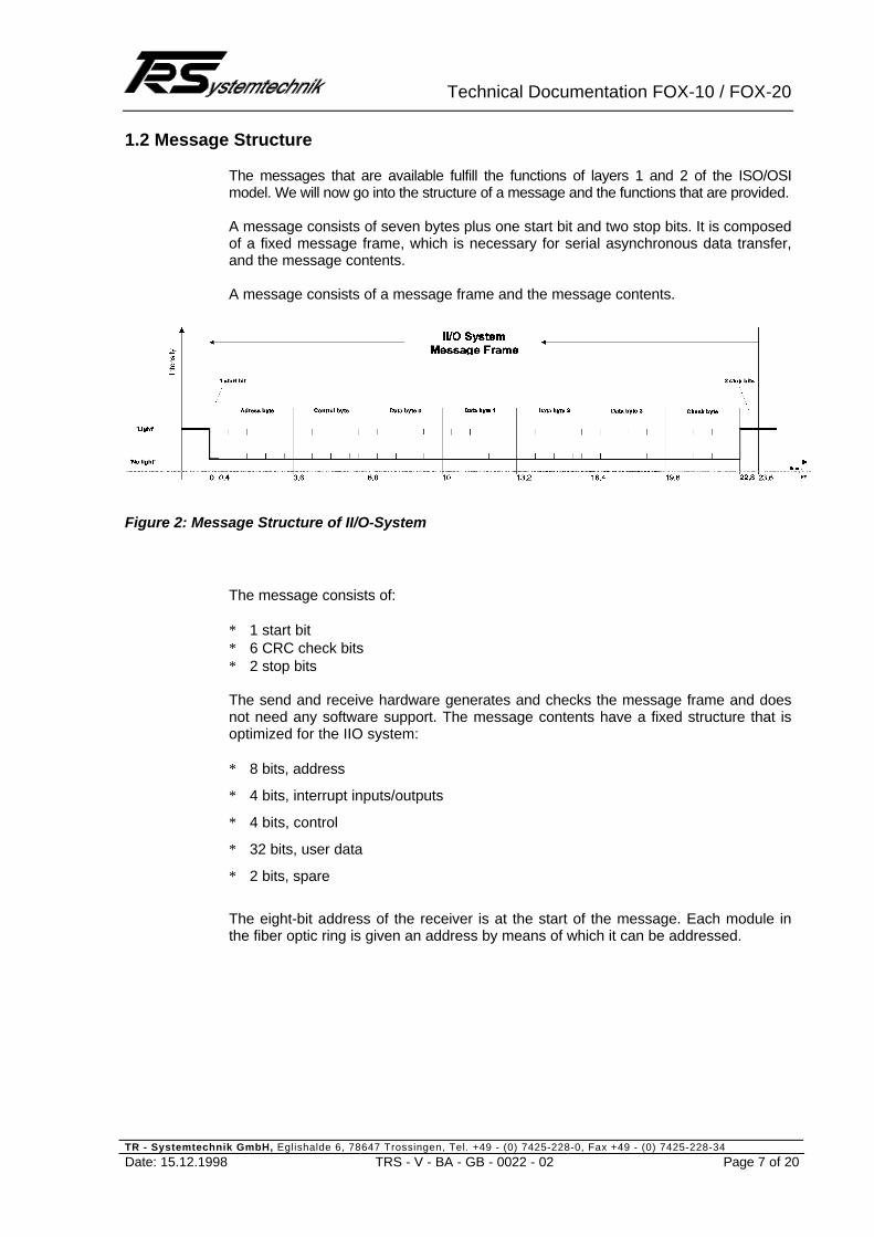
The messages that are available fulfill the functions of layers 1 and 2 of the ISO/OSImodel. We will now go into the structure of a message and the functions that are provided.
A message consists of seven bytes plus one start bit and two stop bits. It is composedof a fixed message frame, which is necessary for serial asynchronous data transfer,and the message contents.
A message consists of a message frame and the message contents.
Figure 2: Message Structure of II/O-System
The message consists of:
∗ 1 start bit∗ 6 CRC check bits∗ 2 stop bits
The send and receive hardware generates and checks the message frame and doesnot need any software support. The message contents have a fixed structure that isoptimized for the IIO system:
∗ 8 bits, address
∗ 4 bits, interrupt inputs/outputs
∗ 4 bits, control
∗ 32 bits, user data
∗ 2 bits, spare
The eight-bit address of the receiver is at the start of the message. Each module inthe fiber optic ring is given an address by means of which it can be addressed.

Technical Documentation FOX-10 / FOX-20
TR - Systemtechnik GmbH, Eglishalde 6, 78647 Trossingen, Tel. +49 - (0) 7425-228-0, Fax +49 - (0) 7425-228-34
Date: 15.12.1998 TRS - V - BA - GB - 0022 - 02 Page 8 of 20
Each receiver module processes the four interrupt bits regardless of the address. Thetransfer chip used in the modules has four interrupt inputs and four interrupt outputs.When a message advances, the system passes the received interrupt bits to thechip's interrupt outputs, logically ORs them with its interrupt inputs and passes on theinterrupt bits.
The four control bits are used to define the type of message. The following types ofmessage are defined:
Read: Read module data
Read/Write: Write data to module and read data of module
Address Initialization: Address assignment to a module
Address Check: Position determination of an address in the ring
Intensity Test: Reduction of the transmission intensity
Apart from this, the message contains 32 bits of user data organized in into fourbytes. The type of module and of message determines processing of the data bytes.
1.3 Message Structure for FOX-10
We will now describe how communication with a module by means of the messagesdescribed above is possible. A module with digital inputs and outputs will be used asan example:
The central unit transmits a message to the module whose user data contains a bitpattern, which the addressed module passes to its digital outputs. At the same time,the system transfers to the central unit the bit pattern of the module's inputs with theuser data of the same returning message. This allows the central unit to use onemessage to not only set the outputs in a module but also to read the module's inputs.
If possible, you should always use Read/Write messages for data communication toand from the FOX-10 (regardless of whether only inputs, only outputs, or inputs andoutputs are used in the module).In this case, the code in the message's control byte always a value of 10 hexadeci-mal.The system always transfers 32 bits of user data in the message frame, i.e. 32 in-put/output bits.This means that it is only possible to address digital inputs/outputs.
Message Type Control Byte FunctionRead/Write: 10 hex Write data to module and read data of module
Address Set 20 hex Address assignment to a module
Address Check andBoxCount
40 hex Read module address and count modules
Low Intensity 90 hex Reduce module's transmitter to 70% of transmissionpower
Important: With a FOX-20, there is a different control byte for Read/Write:
FOX-20 Read/Write 30 hex Write data to module and read data of module

Technical Documentation FOX-10 / FOX-20
TR - Systemtechnik GmbH, Eglishalde 6, 78647 Trossingen, Tel. +49 - (0) 7425-228-0, Fax +49 - (0) 7425-228-34
Date: 15.12.1998 TRS - V - BA - GB - 0022 - 02 Page 9 of 20
1.4 Message Structure for FOX-20
In addition to digital submodules, FOX-20 allows the use of analog ones.In this case, there are only 16 bits of user data in the message. One data byte is usedfor addressing the slot and the channel number (KanalNr.) within a slot.
The structure of the relevant data in the message looks like this:
1.) Every analog channel access is carried out by a (1) message.Every access to a digital submodule (SubModul) is carried out by a (1) message.
2.) A new code (30 hex) is defined as the ControlByte.30 hex means FOX-20 message.
3.) In data byte (DatenByte) 0 of the message, the FOX-20-internal channel ad-dress.DB0 is divided into two:The upper nibble contains the number of the submodule. The first submodulethat is fitted on the left-hand slot of the FOX-20 basic module is given submodulenumber 1.This means that, reading from left to right, the possible numbers are 1, 2, 3 and4.The lower nibble defines the channel of the submodule. Example: Analog inputchannel 1 is given channel number 1, etc.MAI4 and MAO4 have four input and output channels respectively that have theaddresses 1, 2, 3, 4.If you plug digital submodules in the FOX-20, they are addressed with the slotnumber. In this case, the channel number with digital submodules is always 0.
4.) The actual user information is in DB2 and DB3.DB2 contains the low byte, and DB3 contains the high byte.With analog inputs, the system always returns the value as a 16-bit word; thevalue appears virtually left-justified in the word even at 12-bit resolution.The missing four bits are interpreted as the least significant ones and the systempads them with 0000.The advantage is that you can use MAI4-12 or MAI4-16 software-independently.The improved resolution of MAI4-16 fills only the least significant four bits in thiscase and improves the resolution.
5.) The first slot (submodule no. 1) in the FOX-20 can take only analog submodules.You can fit the rest of the slots (submodule nos. 2 to 4) with a mixture of analogor digital submodules.

Technical Documentation FOX-10 / FOX-20
TR - Systemtechnik GmbH, Eglishalde 6, 78647 Trossingen, Tel. +49 - (0) 7425-228-0, Fax +49 - (0) 7425-228-34
Date: 15.12.1998 TRS - V - BA - GB - 0022 - 02 Page 10 of 20
1.5 Overview of Messages for FOX-20 (Digital and Analog Submodules):
Message structure:
ADR = Module Address = 1 .. 254 decContrlByte = Read/Write FOX-20 = 30 hexDB0 = ChannelSelect = HighNibble := SubModuleSlot 1..4
LowNibble := ChannelNumber 1..15DB1 = Must be 80 hexDB2 = LSB dataDB3 = MSB data
ADR (1..254) ControlByte DB0 (Bit0..7) DB1(Bit8..15) DB2(Bit16..23) DB3(Bit24..31)
e.g. 1 (Box 1) 0011 0000 Slot Channel 1000 0000 Data LSB Data MSB
Message Table:
Range DB0 DB1 DB2 DB3Slot No./Channel No. Constant Low Byte High Byte
Digital submodule in slot 1 0001 0000 ----------- Not allowed Not allowedDigital submodule in slot 0010 0000 1000 0000 LSB bit pattern xxxx xxxxDigital submodule in slot 3 0011 0000 1000 0000 LSB bit pattern xxxx xxxxDigital submodule in slot 4 0100 0000 1000 0000 LSB bit pattern xxxx xxxx
Analog channel 1 in slot 1 0001 0001 1000 0000 LSB bit pattern MSB bit patternAnalog channel 2 in slot 1 0001 0010 1000 0000 LSB bit pattern MSB bit patternAnalog channel 3 in slot 1 0001 0011 1000 0000 LSB bit pattern MSB bit patternAnalog channel 4 in slot 1 0001 0100 1000 0000 LSB bit pattern MSB bit pattern
Analog channel 1 in slot 2 0010 0001 1000 0000 LSB bit pattern MSB bit patternAnalog channel 2 in slot 2 0010 0010 1000 0000 LSB bit pattern MSB bit patternAnalog channel 3 in slot 2 0010 0011 1000 0000 LSB bit pattern MSB bit patternAnalog channel 4 in slot 2 0010 0100 1000 0000 LSB bit pattern MSB bit pattern
Analog channel 1 in slot 3 0011 0001 1000 0000 LSB bit pattern MSB bit patternAnalog channel 2 in slot 3 0011 0010 1000 0000 LSB bit pattern MSB bit patternAnalog channel 3 in slot 3 0011 0011 1000 0000 LSB bit pattern MSB bit patternAnalog channel 4 in slot 3 0011 0100 1000 0000 LSB bit pattern MSB bit pattern
Analog channel 1 in slot 4 0100 0001 1000 0000 LSB bit pattern MSB bit patternAnalog channel 2 in slot 4 0100 0010 1000 0000 LSB bit pattern MSB bit patternAnalog channel 3 in slot 4 0100 0011 1000 0000 LSB bit pattern MSB bit patternAnalog channel 4 in slot 4 0100 0100 1000 0000 LSB bit pattern MSB bit pattern

Technical Documentation FOX-10 / FOX-20
TR - Systemtechnik GmbH, Eglishalde 6, 78647 Trossingen, Tel. +49 - (0) 7425-228-0, Fax +49 - (0) 7425-228-34
Date: 15.12.1998 TRS - V - BA - GB - 0022 - 02 Page 11 of 20
1.6 FOX-20 Message Examples:
ADR (1..254) ControlByte DB0 (Bit0..7) DB1(Bit8..15) DB2(Bit16..23) DB3(Bit24..31)
e.g. 1 (Box 1) 0011 0000 Slot Channel 1000 0000 Data LSB Data MSB
Example 1: FOX-20 fitted in slot 1 = MAI4 4 analog inputsin slot 2 = MAO4 4 analog outputsin slot 3 = MDI8 8 digital inputsin slot 4 = MDO8 8 digital outputs
1.1) Access to slot 1/analog input channel 1: Analog input voltage is +5V, for example
ADR Control Slot Channel Fixed 80H Corresponds to + 5Vz.B 1 (Box 1) 0011 0000 0001 0001 1000 0000 0000 0000 0100 0000
1.2) Access to slot 2/analog output channel 3: Analog output voltage is +9V, for example
ADR Control Slot Channel Fixed 80H Corresponds to + 7.5Ve.g. 1 (Box 1) 0011 0000 0010 0011 1000 0000 0000 0000 0110 0000
1.3) Access to slot 2/analog output channel 4: Analog output voltage is -1V, for example
ADR Control Slot Channel Fixed 80H Corresponds to -1Ve.g. 1 (Box 1) 0011 0000 0010 0100 1000 0000 0011 0100 1111 0011
1.4) Access to slot 3/Digital input MDI8: Bit pattern 0101 1010
ADR Control Digital channel Fixed 80H Bit Pattern
e.g. 1 (Box 1) 0011 0000 0011 0000 1000 0000 0101 1010 xxxx xxxx
1.5) Access to slot 4/Digital output MDO8: Bit pattern 1100 0011
ADR Control Digital channel Fixed 80H Bit Pattern
e.g. 1 (Box 1) 0011 0000 0100 0000 1000 0000 1100 0011 xxxx xxxx

Technical Documentation FOX-10 / FOX-20
TR - Systemtechnik GmbH, Eglishalde 6, 78647 Trossingen, Tel. +49 - (0) 7425-228-0, Fax +49 - (0) 7425-228-34
Date: 15.12.1998 TRS - V - BA - GB - 0022 - 02 Page 12 of 20
2 Functional Description of Hardware, FOX-10 and FOX-20
FOX-10 Basic Module Fitted with Four Input/Output Modules
FOX-20 Basic Module with Four Analog Inputs, Four Analog Outputs, Eight DigitalInputs, Eight Digital Outputs
GeneralThe FOX-10 Basic Module is the basis of the digital input/output modules for opera-tion in the II/O system with 32 inputs/outputs divided into four eight-bit ports. PortsD0..D3 correspond to the data bytes in the optical waveguide transfer protocol; de-pending on the application, they can be configured as inputs or outputs with a widerange of different modules.The basic module contains the fiber optic adapter, the mains unit as well as four slotsfor plugging in the submodules.
The following submodules are currently available:
nn MDI8 8 digital inputsnn MDO8 8 digital outputs, 24V/0.5Ann MDM8 8 digital power outputs, 24V/2.2Ann MDR8 8 digital relay outputs, 220V/1Ann MAC8-110 8 AC inputs, 110V ACnn MAC8-220 8 AC inputs, 220V AC

Technical Documentation FOX-10 / FOX-20
TR - Systemtechnik GmbH, Eglishalde 6, 78647 Trossingen, Tel. +49 - (0) 7425-228-0, Fax +49 - (0) 7425-228-34
Date: 15.12.1998 TRS - V - BA - GB - 0022 - 02 Page 13 of 20
In FOX-20, you can use the following additional submodules:
nn MAI4 4 analog inputsnn MAO4 4 analog outputsnn MSSI2 2 SSI interfacesnn MINC2 2 incremental countersnn MPWM2 2 pulse width modulation outputs
You can now fit the FOX-10-Basis basic module's four slots with any four submodulesfrom the available range. In the FO message, each of these submodules is repre-sented by one byte.Reading from left to right, data bytes D0, D1, D2 and D3 correspond to the four slots.
In the FOX-20, you can fit three of the slots with any analog and digital submodulesfrom the available range. The first slot can take only analog submodules.
Three diagnostic LEDs are fitted for the II/O fiber optic ring. If there is an interruptionin the cable, the red ‘ERROR’ LED lights up. The ‘Watchdog’ LED is switched on for100 ms when the module is addressed in a cable message, i.e. when it is receiving amessage intended for it. For safety reasons, if an error occurs the system resets anyoutputs of subsequent output modules that may be fitted. The 'Cycle' LED lights upevery time a message is received.
FOX-10 Basic Module
Fiber Optic Ring
LCAPeripheralController Port
PortPort
Port
MDI8orMDO8
MDI8orMDO8
MDI8orMDO8
MDI8orMDO8
8 Inputs/Outputs 8 Inputs/Outputs 8 Inputs/Outputs 8 Inputs/Outputs

Technical Documentation FOX-10 / FOX-20
TR - Systemtechnik GmbH, Eglishalde 6, 78647 Trossingen, Tel. +49 - (0) 7425-228-0, Fax +49 - (0) 7425-228-34
Date: 15.12.1998 TRS - V - BA - GB - 0022 - 02 Page 14 of 20
2.1 Technical Data
Inputs/Outputs Max. of 32 digital I/Os or max. of 16 analogI/Os, or a mixture of both via up to four gal-vanically decoupled submodules.Divided into four ports that can be fitted byte-by-byte with input or output modules (MDI8,MDO8 etc.).LED status indicator on all MD modules
Input Specifications Refer to input modules for FOX-10/FOX-20
Output Specifications Refer to output modules for FOX-10/FOX-20
Output Monitoring Watchdog circuit
Connections Toshiba PCS Fiber Optic System or APS Fiber
Data Connection Fiber Optic Ring II/O System
Transfer Rate 2.5 Mbps, 25 µs for 32 bits
Supply Voltage 24 V DC (±20%)
Current Consumption Approx. 0.1 A (without submodules)
Housing Closed, can be screw-mounted on a devicemounting rail complying with DIN EN 50022,50035
Dimensions (W x H x D) FOX-10: 305 x 76 x 68 mmFOX-20: 315 x 76 x 68 mm
Weight Approx. 750 g
Operating Temperature ±0..+55° C
Storage Temperature -20..+70° C

Technical Documentation FOX-10 / FOX-20
TR - Systemtechnik GmbH, Eglishalde 6, 78647 Trossingen, Tel. +49 - (0) 7425-228-0, Fax +49 - (0) 7425-228-34
Date: 15.12.1998 TRS - V - BA - GB - 0022 - 02 Page 15 of 20
2.2 Installation Information
Assembly
You connect the FOX-10/FOX-20 to the II/O Fiber Optic Ring using (ToshibaTOCP155) fiber optic cable plug-in connectors. The maximum length of the fiber opticcable to the next box should not exceed 45 meters with plastic cables and 600 meterswith glass fiber ones. These values only apply if you lay the cables with bending radiiof at least 30 mm. With plastic fiber optic cables, you do not need any special tools toassemble the connectors.
Commercially available three-wire (+,-, signal) actuators and sensors are directlyconnected to the input and output modules' inputs and outputs.
You mount the FOX-10/FOX-20 decentrally on the machine or in the switching cabi-net by simply screwing it to a device mounting rail that complies with DIN EN 50022or DIN EN 50035.
Configuration
FOX-10: You can configure every port in the FOX-10 – independently of all the others –as an input module or as an output module. You do not need to make any settings (ofDIP switches, for example) to differentiate between input and output modules. Simplyfitting the appropriate modules in the four possible ports is enough to define the 32possible inputs/outputs.
FOX-20: You can only fit an analog submodule in the first slot on the left-hand side(Slot 1). In the rest of the slots, you can fit analog and/or digital submodules.
Power Supply
You connect the power supply for the control logic via the four-pin connection terminal,X10.

Technical Documentation FOX-10 / FOX-20
TR - Systemtechnik GmbH, Eglishalde 6, 78647 Trossingen, Tel. +49 - (0) 7425-228-0, Fax +49 - (0) 7425-228-34
Date: 15.12.1998 TRS - V - BA - GB - 0022 - 02 Page 16 of 20
2.3 Pin Assignments
Connector X10:
Pin Signal Description
1 +24 V logic Control voltage supply
2 GND logic Ground of logic
3 +24 V logic Control voltage supply
4 GND logic Ground of logic
Connectors X90 / X91:
Pin Signal Description
X90 FO-OUT Fiber optic ring OUTPUT
X91 FO-IN Fiber optic ring INPUT
2.4 Meanings of the LEDs
Three LEDs provide information about the status of the module.The LEDs are from top to bottom:
LED Color Meaning
1 Green Watchdog that is triggered on each write message
2 Red Error LED: the module reports a faulty message
3 Green Cycle: shows message traffic
2.5 Setting the Transmission Power
In the LED connection cap, there is a rotary switch that you can turn from outside us-ing a small screwdriver. A green LED shows the switch setting: if the LED is lit up, thetransmission power is set to 10 m .. 45 m; otherwise, the system runs at a power re-duced by 4 dB with fiber optic cable lengths of 0.2 m .. 15 m.

Technical Documentation FOX-10 / FOX-20
TR - Systemtechnik GmbH, Eglishalde 6, 78647 Trossingen, Tel. +49 - (0) 7425-228-0, Fax +49 - (0) 7425-228-34
Date: 15.12.1998 TRS - V - BA - GB - 0022 - 02 Page 17 of 20
3 Appendix
3.1 Types of Fiber Optic Cable
Two basic types of fiber optic cable are available, i.e. all plastic fiber, APF and plasticcladding silica fiber, PCS. You can lay both types on a trailing cable chain, since thevarying load meets the requirements. The fiber optic cable transmission and receptionchips are designed for APF as well as PCS cables. APF cables guarantee safe datatransmission up to 45 meters; with PCS cables, this distance is 300 meters. Usingspecial transmission chips with PCS cables, you can achieve distances of up to1000 meters.
PCS cables need different connectors from APF cables, however the II/O modulesare identical (up to 300 meters). In addition, you need special tools for PCS cables.
You can use a measuring instrument to measure the attenuation of the cable or of theconnector.
The II/O modules are connected to the bus link via fiber optic plug-in connectors X90and X91 as shown in figure 2.
3.2 Preparing the Fiber Optic Connector
It is quite easy to prepare the fiber optic connector on the APF cable. First of all, youstrip about 25 mm of the 6-mm polyurethane jacket and cut off the Kevlar strain reliefappropriately without damaging the black internal sheath. After this, strip 7 mm of theblack internal sheath using a cable stripper or a special cable-stripping tool. Under nocircumstances must you damage the transparent fiber while doing this. Ensure thatthe cut surface of the fiber does not split. By feeding in red light at the other end ofthe fiber, you can check the end of the fiber. You then push the fiber from the back allthe way in to the connector and then push in the clamping fixture in to the connectorusing a screwdriver or similar tool. After this, sand the end of the fiber that is stickingout of the connector at right angles to the connector; to do this, first use 600 grain andthen 1000 grain emery paper. You must not sand the connector itself. Do not use anychemical-based polishing pastes, as they harden the fiber. It is sensible to use amagnifying glass to check the results.

Technical Documentation FOX-10 / FOX-20
TR - Systemtechnik GmbH, Eglishalde 6, 78647 Trossingen, Tel. +49 - (0) 7425-228-0, Fax +49 - (0) 7425-228-34
Date: 15.12.1998 TRS - V - BA - GB - 0022 - 02 Page 18 of 20
Figure: Preparation of Fiber Optic Connectors
3.3 Information on Laying Fiber Optic Cables
• Unroll cables from the drum or the coil do not pull them off in loops.
• Max. tensile load per wire: One off 80 N
• Minimum bending radius: One off 10 mmContinuous 20 mm (0.5 dB attenuation)With varying load: 50 mm
• With duplex fibers, slit the last 150 mm before the connection.
• Protect the ends of the fibers from dirt.
It is sensible to measure the signal arriving at the receiver using a fiber optic cablemeasuring instrument. The reception level must be between -15 dB and -27 dB.

Technical Documentation FOX-10 / FOX-20
TR - Systemtechnik GmbH, Eglishalde 6, 78647 Trossingen, Tel. +49 - (0) 7425-228-0, Fax +49 - (0) 7425-228-34
Date: 15.12.1998 TRS - V - BA - GB - 0022 - 02 Page 19 of 20
3.4 Attenuation Calculations
The distances that can be covered by optical fiber cables depend on the highest andlowest transmission and reception powers and the attenuation of the transmission link.The red light transmitted by the fiber optic transmitters has a wavelength of 650 nm.The transmission power is approximately -11 dB. Some II/O modules can be switchedbetween -10 dB and -14 dB.
The reception power must be between 31 µµW = -15 dB and 2 µµW = -27 dB.
The reception power reduces by half for every ten meters of APF cable, this corre-sponds to -3 dB.
Depending on the workmanship, a connector connection has an attenuation of between-1.5 dB and -3 dB. With particularly careful workmanship, it is possible to achieve valuesbelow -1 dB.
The level n in dBm specifies the power, P, as a logarithmic number relative to1 mW = 1000 µW. In this calculation, you should note the minus sign for the attenua-tion (this corresponds to the plus sign for the gain).
P/µWn = 10 * log P/mW = 10 * log --------
1000
Example: if 30 µW = 10 log, 0.03 mW = -15.2 dBm
In practice, you carry out the calculation directly in dB, whereby you simply add up theindividual attenuation values.
Example:
Transmission power: = -11 dBmAttenuation: =Two -2-dB connectors, 20 m fiber optic cable = -6 dBReception power: = -11 dBm -4 dB -6 dB = -21 dBm

Technical Documentation FOX-10 / FOX-20
TR - Systemtechnik GmbH, Eglishalde 6, 78647 Trossingen, Tel. +49 - (0) 7425-228-0, Fax +49 - (0) 7425-228-34
Date: 15.12.1998 TRS - V - BA - GB - 0022 - 02 Page 20 of 20
3.5 Type Code
FOX -10 -A - B - C - DType of slot 4 (on right)Type of slot 3Type of slot 2Type of slot 1Type of basic module (on left)
Type Designation Description
FOX Fiber Optic Box System, basic module for max. of 4 Interfacemodules
FOX-10 FOX-10 Basic module for a maximum of four submodules of typeMDI8, MDO8, MDL8, MDM8, MDR8, MAC8
FOX-20 FOX-20 Basic module for a maximum of four submodules of typeMDI8, MDO8, MDL8, MDR8, MAC8, MAI4, MAO4
Submodules:-A MAB Blanking plate instead of a submodule-B MDI8 Submodule 8 digital inputs, 24 V DC-C MDO8 Submodule 8 digital outputs 24 V DC / 0.5 A-D-E MDR8-001 Submodule 8 relay, same as F without protective circuitry-F MDR8 Submodule 8 relay outputs, 220 V AC / 2.0 A max.-G MAC8-110 Submodule 8 digital AC inputs, 110 V AC-H MAC8-220 Submodule 8 digital AC inputs, 220 V AC-K MDM8 Submodule 8 digital DMOS power outputs, 24 V / 2.0 A-L MAI4-12 Submodule 4 analog inputs-N MAI4-16 Submodule 4 analog inputs-M MAO4 Submodule 4 analog outputs-O MSSI-2 Submodule 2 SSI interfaces-P MINC-2 Submodule 2 incremental counters-R
Example: Basic module fitted with (from left to right):8 digital inputs8 digital outputs8 relay outputs, 220VEmpty spare slot
Order No. : FOX-10-BCFA
s1
m1
ö1
s2
m2
ö2
s3
m3
ö3
s4
m4
ö4
s5
m5
ö5
s6
m6
ö6
s7
m7
ö7
s8
m8
ö8
NN
N