Fourth unittheory
34
UNIT IV FORCED VIBRATION 9 Response of one degree freedom systems to periodic forcing – Harmonic disturbances –Disturbance caused by unbalance – Support motion – transmissibility – Vibration isolation vibration measurement. 4. Forced Vibration There is no influence of external forces in the free vibration of a system. Think of a child swinging on a swing. A child swinging freely on a swing will do so consistently. It consistently takes two to three seconds to a complete each cycle of swinging. Think of an oscillating pendulum. The vibration of a pendulum needs no external force to vibrate. A machine left to vibrate freely will tend to vibrate at its natural oscillation (vibration) rate. In forced vibration of a system, it is under the influence of external force applied on the system. The vibration of a machine like a drill is forced vibration. It needs an external force to vibrate. External forces are applied forces. An applied force is a force that is applied to an object by a person or another object. If a person is pushing a desk across the room, then there is an applied force acting upon the object. The applied force is the force exerted on the desk by the person. Similarly the force applied by the waves on the boat. A boat anchored in a bay is subjected to repeated waves slapping on the sides of the boat. The boat rocks as long as the waves continue to act on the boat. Most machine vibrations are also similar. The vibrations are due to repeating forces acting on its components. Repeating (Periodic!) forces in machines are mostly due to the rotation of imbalanced (uneven rotor, bent shaft), misaligned (improper mounting, distortion due to fastening torque), worn (worn belt, gear teeth), or
-
Upload
vaidyanathan-ramakrishnan -
Category
Education
-
view
12 -
download
0
Transcript of Fourth unittheory

UNIT IV FORCED VIBRATION 9
Response of one degree freedom systems to periodic forcing – Harmonic disturbances –Disturbance caused by unbalance – Support motion –transmissibility – Vibration isolation vibration measurement.
4. Forced Vibration
There is no influence of external forces in the free vibration of a system. Think of a child swinging on a swing. A child swinging freely on a swing will do so consistently. It consistently takes two to three seconds to a complete each cycle of swinging. Think of an oscillating pendulum. The vibration of a pendulum needs no external force to vibrate. A machine left to vibrate freely will tend to vibrate at its natural oscillation (vibration) rate.
In forced vibration of a system, it is under the influence of external force applied on the system.The vibration of a machine like a drill is forced vibration. It needs an external force to vibrate.
External forces are applied forces. An applied force is a force that is applied to an object by a person or another object. If a person is pushing a desk across the room, then there is an applied force acting upon the object. The applied force is the force exerted on the desk by the person. Similarly the force applied by the waves on the boat.
A boat anchored in a bay is subjected to repeated waves slapping on the sides of the boat. The boat rocks as long as the waves continue to act on the boat.
Most machine vibrations are also similar. The vibrations are due to repeating forces acting on its components.Repeating (Periodic!) forces in machines are mostly due to the rotation of imbalanced (uneven rotor, bent shaft), misaligned (improper mounting, distortion due to fastening torque), worn (worn belt, gear teeth), or improperly driven (intermittent bush contact in motors, misfiring in IC engine cylinder, uneven air supply) machine components.
4.1 Types of forces causing vibration
Types of forces (forcing function!) that cause vibration are:
1. Random forcing2. Impulsive forcing3. Periodic forcing
1. Random forcing:

These are unpredictable and non-deterministic (difficult to determine the magnitude using expression)Examples: Ground motion during earth quake, jet engine noise.
2. Impulsive forcing: They are short duration forces and non-periodic. The vibrations die out soon and are not significant.Examples: Rock explosion, gun firing, punching die.
3. Periodic forcing: These are predictable and deterministic (magnitude given by an expression).Example: Centrifugal (unbalanced) forces caused by an eccentric rotating mass, Inertia (unbalanced) forces caused by reciprocating mass in an IC engine.
4.1.1 Types of forced vibrations
Classifications based on forces causing vibrationI. Forced vibrations are classified according to the type of forces causing the excitation:1. Random vibration2. Transient vibration3. Steady state vibration
1. Random vibration: Vibrations caused by random forces are called random vibration.Examples: Ground motion during earth quake, jet engine noise.
2. Transient vibration: Vibrations caused by impulsive forces and which are of short duration are called transient vibration.Examples: Rock explosion, gun firing, punching die.
3. Steady state vibration: Periodic vibration with constant amplitude is called steady state vibration.Example: Centrifugal (unbalanced) forces caused by an eccentric rotating mass under steady state, Inertia (unbalanced) forces caused by reciprocating mass in an IC engine under steady state.
II. Classifications based on damping resistance Forced vibrations are also classified into two types based on the existence of damping resistance:
1. Undamped forced vibration (c = 0)2. Damped forced vibration (c ≠ 0)
where ‘c’ is damping coefficient N/(m/s)
1. Undamped forced vibration (c = 0): When the damping resistance is nil in a forced vibration, it is called undamped forced vibration.
2. Damped forced vibration (c ≠ 0): When the damping resistance is present in a forced vibration, it is called damped forced vibration.
4.2 Periodic forcing

A force which acts continuously at specific intervals of time is called periodic force. There are two types of periodic forcing:1. Harmonic forcing and 2. Non-harmonic forcing.
1. Harmonic forcing: When the applied load (force!) varies as a sine or cosine function, it is called harmonic forcing.Example:Sine loading: f(t) = F sin (ωt)Cosine loading: f(t) = F cos(ωt)
The response of a system to a harmonic excitation (loading!) is called harmonic response.
2. Non-harmonic forcing: . Any harmonic function such as sin or cosine is periodic. But the converse is not true. Non-harmonic forcing is a type of periodic function that is discontinuous. The restoring force is independent of displacement. It can be represented by either a discrete or combination of sin and cos functions.Example: F(t+tp) = F(t) where t is time, tp is time period
4.2.1 Response to periodic forcing
Forces acting on any vibrating machine system can be represented in mathematical equationm x+kx=k y (ωt )
whereωt=nπ ,nis an integer .
Consider a system as shown in Fig.14.5.1

A roller is guided in the groove of a face cam generates motion from the point O. It is a single degree of freedom system The displacement is expressed by the relation
y (ωt )=ω0 (1−cosωt )
The far end of the spring of stiffness ‘k’ connected to the sliding mass ‘m’ is assumed as zero. The roller is assumed to be in its extreme left position when the cam begins zero.
[Note: By appropriately choosing the initial zero position (A), we can also express the displacement by the relation y A (ωt )= y0sin ωt ]
The differential equation of motion is now
m x+kx=k ω0 (1−cosωt )The solution of this differential equation is
x=A cos ωn t+B sin ωnt+ y0[1− cos ωt
1−( ωωn
)2 ]
Substituting the boundary conditions, x (0 )=0 , x (0 )=0
A=( ωωn )
2
y 0
[1−( ωωn )
2]∧B=0
Substituting the coefficient values,
The complete simplified equation of motion is

x=( ωωn )
2
y0 cos ωn t
[1−( ωωn )
2]−
y0 cosωt
[1−( ωωn )
2]+ y0
The total motion contains a constant plus two vibrations of differing amplitudes and frequencies.
The first term on the right hand side
( ωωn )
2
y0 cosωn t
[1−( ωωn )
2]is called starting transient. This is not forcing frequency. This is a vibration at natural frequency ωn. The presence of friction (damping!) would cause this term to die out after a short period of time.
Forωωn
=0 ,weget the rigidbody solution
x= y0 [ 1−cos ωt ]
If the spring is replaced by a rigid member then k and ωn become very large. So the mass exactly follows the cam motion.
4.2.2 Harmonic disturbances
A part of any moving or rotating machinery is often subjected to forces which vary periodically with respect to time. The parts which are metal elements have both mass and elasticity. Therefore there is a vibration exists. Since machines normally operate at constant speeds and constant output, vibratory forces may have a constant amplitude over a period of time. These varying forces also may vary in magnitude with speed and output. It is general practice to analyse the vibration problems assuming periodically varying force of constant amplitude.
4.2.3 Equation of motionHere we shall consider the application of a single sinusoidal force. The solution contains components of motion at two frequency levels. One at forcing frequency and the other at natural frequency of the system.Since damping is always present in actual systems, component at natural frequency level becomes insignificant after a certain time.Therefore the component that contains only forcing frequency remains. This motion is called steady state motion.

The equation of motion is m x+c x+kx=F0 cosωt
Complete solution
The complete solution of this equation is
x=e−ξ ωn t (C1sin qt+C2 cosqt )+F0 cos (ωt−ϕ )
√ (k−mω2 )2+c2ω2
(i) Transient response
The first term on the right hand side (RHS) of the complete solution is a transient term. The exponential part will cause it to decay in a short period of time.
(ii) Steady state response
When the transient part dies out, only the second part remains. Since this is neither the beginning nor the end, it is called steady state solution.The following expressions are introduced to obtain simplified solution.
Inertia force=mω2 X
Damping force=cωX
Spring force=kX
Exciting force=F0
ωn=√ km
ξ= ccc
cc=2mωn
X
( F0
k )= 1
√(1− ω2
ωn2 )
2
+(2ξωωn
)2
( F0
k ) = Deflection that a spring of stiffness ‘k’ would experience if acted upon by a force F0.
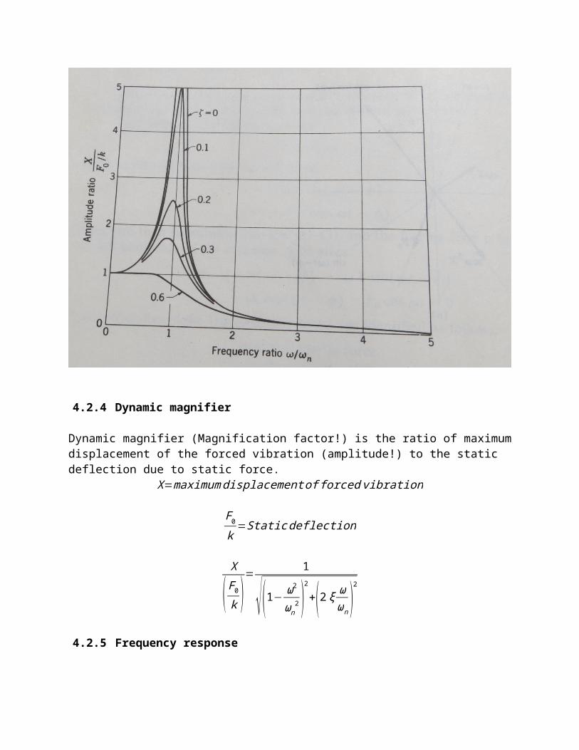
The plot of frequency response namely Amplitude ratio vs Frequency ratio is shown in Fig.15.6

4.2.4 Dynamic magnifier
Dynamic magnifier (Magnification factor!) is the ratio of maximum displacement of the forced vibration (amplitude!) to the static deflection due to static force.
X=maximumdisplacement of forced vibration
F0
k=Static deflection
X
( F0
k )= 1
√(1− ω2
ωn2 )
2
+(2ξωωn
)2
4.2.5 Frequency response

4.3 Disturbance caused by unbalance Most of the machines like motors, compressors, engines produce vibrations due to rapid rotation of a small unbalanced mass. The differential equation for such systems is
m x+kx=mu eω2cos ωtm=vibratingmass
mu=unbalanced masse=eccentricity
4.2.1 Rotating unbalance
The following expressions are introduced to obtain simplified solution.
m=vibratingmassmu=unbalanced mass
e=eccentricity
The simplified solution is X
(mu e
m )=
ω2
ωn2
√(1− ω2
ωn2 )
2
+(2ξωωn
)2
The plot of frequency response namely Amplitude ratio vs Frequency ratio is shown in Fig.16.2Fig17.34P589
From the plot we conclude that at high speeds, where the frequency ratio ( ωωn
) is greater than
unity, amplitude X can be reduced only by reducing the mass and eccentricity of the rotating unbalance.

Relative motion:
Zy0
=
ω2
ωn2
√(1− ω2
ωn2 )
2
+(2ξωωn
)2
4.2.2 Reciprocating unbalance
In a reciprocating engine, there is an unbalanced primary inertia force given by mω2 r cosθThis primary unbalanced force always acts along the line of stroke with varying magnitude.

This reciprocating unbalance can be considered as the horizontal component of an imaginary rotating mass m kept at crank radius r (crank pin!).Now balancing is done in the same way as we have done for rotating unbalance.Let the balancing be done by balancing mass mB at radius rB.The reciprocating unbalance force = Horizontal component of rotating balancing mass
mω2 r cosθ=mB ω2 rB cosθHowever the balancing mass also has a vertical component of its centrifugal force namely
mBω2r B sinθThis remains unbalanced. Therefore when we attempt to balance horizontal component, a vertical unbalance is introduced!To minimize the unbalance, a compromise is therefore made. Only a fraction (c ) of the reciprocating mass is balanced.
cmr=mB rB
If there exists both reciprocating as well as rotating unbalance in a machine, thenmB r B=(mu+c m ) r
4.2.3 Damping factor (ξ)
Damping factor (damping ratio!) is the ratio of actual damping coefficient, c to critical damping coefficient, cc.
ξ= ccc
If ξ>1 ,then the systemis
damped.
If ξ=1 , thenthe system is critically dampedIf ξ>1 ,then the systemis under damped

4.2.4 Steady state response
The simplified solution for steady state response X is

X
(mu e
m )=
ω2
ωn2
√(1− ω2
ωn2 )
2
+(2ξωωn
)2
4.2.5 Absolute amplitude
The simplified solution for absolute amplitude X is
X
(mu e
m )=
ω2
ωn2
√(1− ω2
ωn2 )
2
+(2ξωωn
)2
4.2.6 Relative amplitude
The relative amplitude Z is

From the plot we conclude that at high speeds, where the frequency ratio ( ωωn
) is greater than
unity, amplitude X can be reduced only by reducing the mass and eccentricity of the rotating unbalance.
Relative motion:
Zy0
=
ω2
ωn2
√(1− ω2
ωn2 )
2
+(2ξωωn
)2
4.2.7 Phase angleThe direction of F0cos (ωt ) will always be ahead of kX cos (ωt−ϕ ) by angle ϕ.The phase angle ϕ is
ϕ=tan−1
2ξωωn
(1− ω2
ωn2 )
4.2.8 Resultant force on motorResultant force on motor is the resultant of the forces exerted by the spring and dashpot
4.2.9 Resonance speedLet N be the speed of the driving shaft of the motor at which resonance occurs.The angular speed at which resonance occurs is given by
ω=ωn=√ km

Resonance speed N is obtained from the relation
ω=2πN60
4.2.10 Amplitude of resonanceAmplitude of resonance X is obtained by substituting ω=ωn in the relation
X
(mu e
m )=
ω2
ωn2
√(1− ω2
ωn2 )
2
+(2ξωωn
)2
X
(mu e
m )= 1
√(2ξωωn
)2= 1
2ξωωn
X
(mu e
m )= 1
2ξωωn
4.4 Support motion
Support motion is also called base excitation. In many situations, the excitation is created (applied!) by the base or support configuration. Example: sinusoidal profile of a road.

4.2.11 Absolute amplitudeAbsolute harmonic displacement of support is y = Y sin ωtAbsolute displacement of mass m is x.Absolute differential equation of motion is
m x+c x+kx=Y √k2+c2 ω2 sin (ωt+α )
F0=Y √k2+c2 ω2
4.2.12 Relative amplitudeRelative amplitude is z = y-x, where x is absolute displacement of mass m.Relative differential equation of motion is
m z+c z+kz=mω2Y (sinωt )

F0=mω2 Y
4.2.13 Circular frequency of vibration
Natural circular frequency of motion ωn=√ km
Time period=Wave lengthVelocity
→t p=λv
4.2.14 Vertical amplitude of vibrationSteady state amplitude due to excitation of support,
X=
Y √1+(2ξωωn
)2
√[1−( ωωn
)2]
2
+(2ξωωn
)2
4.3 Vibration isolation
Vibrations are produced in all machines having motion of unbalanced masses. These vibrations will be transferred to the foundation or base supports upon which the machines are installed. This will result in noise, wear, and failure of machine as well as the structure. Hence this is not desirable and needs to be eliminated (isolated!). If not at least diminish to acceptable limits.
4.3.1 TransmissibilityTransmissibility is defined as the ratio of force or displacement transmitted to the foundation to the vibrating force or displacement applied by the unbalance. Transmissibility is a measure of effectiveness of the vibration isolating material.
1. Force transmissibilityIn order to reduce the transmitting forces to the foundation, machines are mounted on springs and dampers or some other isolation materials like cork, rubber which have these properties.

Definition: Force Transmissibility is defined as the ratio of force transmitted to the foundation to the vibrating force applied by the unbalance. Transmissibility is a measure of effectiveness of the vibration isolating material.Force transmissibility is also called as isolation factor.
Transmissibility vs Frequency ratio
The transmitted force to the foundation is a vector sum of spring force (kX) and damping force (cωX). The spring force and damping force act perpendicular to each other. Therefor the resultant transmitted force Ft is
F t=√(kX )2+ (cωX )2=X √k2+ (cω )2.
X
( F0
k )= 1
√(1− ω2
ωn2 )
2
+(2ξωωn
)2
Multiplying the above two equationsF t kX
F0
=X √k2+ (cω)2
√(1− ω2
ωn2 )
2
+(2ξωωn )
2
→F t
F0
=1k
√k2+(cω )2
√(1− ω2
ωn2 )
2
+(2ξωωn )
2
→F t
F0
= √1+( cωk )2
√(1− ω2
ωn2 )
2
+(2ξωωn
)2 (1)
We know that ωn=√ k
m;ξ= c
cc
; cc=2mωn;→m=cc
2ωn
=( cξ )2ωn
= c2ξ ωn
→ωn=√ k (2ξ ωn )c
→ωn2=
k (2ξωn )c
→ωn=k2ξc
→ck=2ξ
ωn
Substituting the value for ( ck ) in equation (1)

Transmissibility , ε=Ft
F0
=√1+(2ξ
ωωn
)2
√(1− ω2
ωn2 )
2
+(2ξωωn
)2
At resonance, ωωn
=1
Hence Transmissibility , ε=Ft
F0
=√1+(2ξ )2
2ξ
With no damper, c=0 and ξ=ccc
=0
Hence Transmissibility , ε=
Ft
F0
=±1
√(1− ω2
ωn2 )
2
Transmissibility regions
A plot of ε vs( ωωn
) can be drawn for different values of ξ.
The observations from the plot are
1. Critical value of ( ωωn
)=√2
2. When ( ωωn
)>√2, then ε<1
3. When ( ωωn
)<√2, then ε>1
4. When ( ωωn
)=√2 ,then ε=1
5. When ( ωωn
)=1 , thenε=∞
6. Up to ( ωωn
)=1, increasing ( ωωn
) increases ε
7. Beyond ( ωωn
)=1, increasing ( ωωn
) decreases ε
8. Note that as damping c∨ξ is increased, ( ωωn
) decreases. Therefore for various regions,
the effect of damping varies as above.

Include examples from excel file Q15and
Example: A machine supported symmetrically on four springs has a mass of 80 kg. The mass of the reciprocating part is 2.2 kg which move through a vertical stroke of 100 mm with simple harmonic motion. Neglecting damping, determine the combined stiffness of the springs so that the force transmitted to the foundation is 1/20th of the impressed force.
The machine crankshaft rotates at 800 rpm. If under actual working conditions, the damping reduces the amplitudes of successive vibrations by 30%, find:
(i) the force transmitted to the foundation at 800 rpm,(ii) the force transmitted to the foundation at resonance, and(iii) the amplitude of the vibrations at resonance.
Unit – 4 November/December 2006; Unit – 4 November/December 2008; Unit – 4 May/June 2009; Unit – 4 November/December 2009Unit – 4 NOVEMBER/DECEMBER 2010KJ10.38.22Given: Mass of machine m = 80 kg; No. of support springs n = 4;Mass of reciprocating parts mR = 2.2 kg; Vertical stroke of SHM L = 0.1 m;Neglect damping; Force transmitted to foundation = (1/20) impressed force;Speed of machine crank shaft = 800 rpm;Damping reduces amplitudes of successive vibrations by 30%;Find: (a) Combined stiffness of spring; (b) Force transmitted to the foundation at 800 rpm;(c ) Force transmitted to the foundation at resonance; and (d) Amplitude of vibration at resonance.
Solution:mass, m= 80 kg

Stroke length, L = 0.1 m; Hence, eccentricity e=crank radius r = L/2= 0.05 m
Assuming no damping, i.e. c = 0 and ξ=0 we find ωn
Hence , Resonant frequency,
Speed ,N=800 rpm
Circular frequency ,ω=2 π f =2π x13.3333=¿
Logarithmic decrement ,∂=1n
ln( x0
xn)=ξ ωn td=
2πξ
√1−ξ2=1
1ln( 1
0.7 )=¿
∴ keq=ns k ;k=keq
ns
=26758.24
=¿
DampingFactor ,ξ= cccr
=√ ∂2
4π 2+∂2=¿
Impressed force ,F0=m0 ω2e=2.2 x83.80952 x 0.05=¿
Force transmitted , FT=ɛ x F0=0.05 x702.404=¿
Impressed force ,F0=m0 ω2e=2.2 x18.28872 x 0.05=¿
Transmissibility ratio , ɛ=FT
F0
=√1+[2ξ ( ω
ωn)]
2
√[1−( ωωn )
2]2
+[2ξ ( ωωn )]
2
¿ √1+2x 0.05665
√ [2 x0.05665 ]2+0=¿
Transmissibility ratio , ɛ=FT
F0
=√1+[2ξ ( ω
ωn)]
2
√[1−( ωωn )
2]2
+[2ξ ( ωωn )]
2=0.05
Substituting valuesωωn
=1∧ξ=0.05665,

The four springs in parallel,
Example: Find the stiffness of each spring when a refrigerator unit having a mass of 30 kg is to be supported by three springs. The force transmitted to the supporting structure is only 10% of the impressed force. The refrigerator unit operates at 420 r.p.m. (16) Unit – 4 November/December 2005
JK10.36.20Given: Mass of refrigerator unit m = 30 kg; No. of support springs n =3;Force transmitted to support structure = 0.1 impressed forceSpeed of the unit = 420 rpmFind: (a) Stiffness k of each spring; (b) Deduce the expression for transmissibility. Solution:mass, m= 30 kg;
420 rpm Hence, f=420/60= 7 Hz
44 rad/s
0.1
No damping; Hence, damping coefficient, c = 0 Ns/m
0
ωn=√ keq
m=√ keq
80=12.2887
Force transmitted at resonance , FT=ɛ x F0=8.88219x 36.7926=¿
M .F .= AX0
=¿ 1
√[1−( ωωn
)2]
2
+[2ξ ( ωωn
)]2
¿ 1
√ [1−1 ]2+[2 x0.05665 (1 ) ]2=¿
Amplitude at resonance , A=M .F . x X0=M .F .F0
k eq
=36.792626758.2
=¿
Speed ,N=¿
Circular frequency ,ω=2 π f =2π x7=¿
Transmissibility , ɛ=FT
F0
=¿
DampingFactor ,ξ= cccr
= 0ccr
=¿

Substituting in the equation,
11
13.2665 rad/s
5280 N/m
Since the three springs are in parallel,
Therefore stiffness of each spring, 1760 N/m
2. Motion transmissibilityDefinition: Motion transmissibility is the ratio of motion transmitted to the foundation to the vibrating motion applied by the unbalance. Transmissibility is a measure of effectiveness of the vibration isolating material.Motion transmissibility is also called as Amplitude transmissibility.In the case of forced excitation due to support excitation, Motion Transmissibility is the ratio of absolute amplitude of mass of the body to the amplitude of base excitation.Transmissibility is the same whether it is force transmissibility or motion transmissibility.
Transmissibility ratio , ɛ=√1+[2ξ ( ω
ωn)]
2
√[1−( ωωn )
2]2
+[2ξ( ωωn )]
2= √1+0
√[1−( 44ωn )
2]2
+0
=0.10
( 44ωn )
2
= 10.10
+1=¿
Natural frequency ,ωn=44
√11=¿

MotionTransmissibility ,AY
=√1+[2ξ ( ω
ωn)]
2
√[1−( ωωn )
2]2
+[2ξ ( ωωn )]
2
Transmissibility ratio , ε=FT
F0
=√1+[2ξ ( ω
ωn)]
2
√[1−( ωωn )
2]2
+[2ξ ( ωωn )]
2
Phase lagPhase lag between motion of mass (A) and motion of support (Y) (or) FT and F0 is given by the relation:
Phase lag ,φ=ϕ−α=tan−1{ 2ξ ( ωωn
)[1−( ω
ωn)
2] }−tan−12ξ ( ωωn
)4.4 Measurement of vibration
The experimental determination of natural frequencies, mode shapes, and damping ratios is called experimental modal analysis. It is based on vibration measurements that fall within general designation of model testing. The objective of modal testing is to acquire frequency response functions (FRFs) that are accurate and extensive, in both frequency and spatial domains. Prior knowledge of vibration analysis, instrumentation, signal processing, and modal identification are required to understand the modal testing.
The basic aim of modal testing is to obtain (FRF’s) relating to output vibration responses at a number of coordinates of interest. They are in the form of accelerations (velocities, displacements) to input vibration excitations, in the form of driving forces, applied at a given coordinate.
Excitation mechanism; Sensing mechanism; Data acquisition and processing mechanism.
4.4.1 Instruments for vibration measurement Vibration instruments are used to measure frequency, displacement, velocity and acceleration of vibration. The measured values are displayed for

monitoring. The vibration parameters are also analysed for the purpose of appropriate corrective action.
Vibration instruments comprise of transducer, transmitters, data acquisition, display indicators, interface to computers and control devices.
Basic measurement system
A typical measurement set up consists of Signal generator, power amplifier, exciter, force transducer, response transducer, conditioning amplifier and analyser.
Excitation mechanism – It provides input motion in the form of driving force applied at a coordinate. The excitation signals can be in many forms (impulse, random, stepped sine etc.) It can be controlled both in frequency and amplitude.
Sensing mechanism – These are sensing devices known as transducers. Piezo electric transducers are used for measuring force excitation. Transducers generate electric signals proportional to physical parameters one want to measure.
Contactless motion transducers improve the accuracy of dynamic response. Laser vibrometer is a velocity transducer which works on the principle of Doppler frequency shift of a laser beam light scattered from moving surface.
Data acquisition and processing mechanism – The basic objective of the data acquisition and processing mechanism is to measure the signals developed by sensing mechanisms and to ascertain the magnitudes and phases of the excitation forces and responses. These are called analysers. They incorporate functions based on fast Fourier transform algorithm and provide direct measurement of FRFs
Understanding the principles behind signal acquisition and processing is very important for anyone involved with doing vibration measurement and analysis. The validity and accuracy of the experimental results may strongly depend on the knowledge and experience of the equipment user.
Vibration Transducers:
Acceleration sensor:An accelerometer is a device that measures the vibration, or acceleration of motion of a structure. The force caused by vibration or a change in motion (acceleration) causes the mass to "squeeze" the piezoelectric material which produces an electrical charge that is proportional to the force exerted upon it. Since the charge is proportional to the force, and the mass is a constant, then the charge is also proportional to the acceleration.Piezoelectric accelerometers rely on the piezoelectric effect of quartz or ceramic crystals to generate an electrical output that is proportional to applied acceleration. The piezoelectric effect produces an opposed accumulation of charged particles on the crystal. This charge is proportional to applied force or stress. A force applied to a quartz crystal lattice structure alters alignment of positive and negative ions, which results in an accumulation of these charged ions on opposed surfaces. These charged ions accumulate on an electrode that is ultimately conditioned by transistor microelectronics.

Piezoelectric MaterialThere are two types of piezoelectric material that are used in PCB accelerometers: quartz and polycrystalline ceramics. Quartz is a natural crystal, while ceramics are man-made. Each material offers certain benefits, and material choice depends on the particular performance features desired of the accelerometer. Quartz is widely known for its ability to perform accurate measurement tasks and contributes heavily in everyday applications for time and frequency measurements.
Velocity Sensor:
The velocity probe consists of a coil of wire and a magnet so arranged that if the housing is moved, the magnet tends to remain stationary due to its inertia. The relative motion between the magnetic field and the coil induces a current that is proportional to the velocity of motion. The unit thus produces a signal directly proportional to vibration velocity. It is self-generating and needs no conditioning electronics in order to operate, and it has a relatively low electrical output impedance making it fairly insensitive to noise induction.
Applications:
Measurements on Structures or Machinery Casings: Accelerometers and Velocity Sensors are

used in gas turbines, axial compressors, small and mid-size pumps. These sensors detect high frequency vibration signals related to bearing supports, casing and foundation resonances, vibration in turbine/compressor vanes, defective roller or ball bearings, noise in gears, etc.
Displacement measurements relative to rotating shafts: Proximity Probes (capacitance or eddy-current) are used in turbo machinery supported on fluid film bearings, centrifugal compressors, gears and transmissions, electric motors, large pumps (>300HP), some turbines and fans. These sensors detect shaft static displacements, unbalance response, misalignment, shaft bending, excessive loads in bearings, dynamic instabilities, etc.
Accelerometers Advantages Simple to install Good response at high frequencies Stand high Temperature Small size
DisadvantagesSensitive to high frequency noiseRequire external powerRequire electronic integration for velocity and displacement.
Velocity SensorsAdvantages Simple to install Good response in middle range frequencies Stand high temperature Do not require external power Lowest cost
DisadvantagesLow resonant frequency & phase shiftCross noiseBig and heavyRequire electronic integration for displacement
Proximity SensorsAdvantages Measure static and dynamic displacements Exact response at low frequencies No wear Small and low cost
DisadvantagesElectrical and mechanical noiseBounded by high frequencies

Not calibrated for unknown metal materialsRequire external powerDifficult to install
Types of Velocity Sensors:
Electromagnetic linear velocity transducers : Typically used to measure oscillatory velocity. A permanent magnet moving back and forth within a coil winding induces an emf in the winding. This emf is proportional to the velocity of oscillation of the magnet. This permanent magnet may be attached to the vibrating object to measure its velocity.
Electromagnetic tachometer generators : Used to measure the angular velocity of vibrating objects. They provide an output voltage/frequency that is proportional to the angular velocity. DC tachometers use a permanent magnet or magneto, while the AC tachometers operate as a variable coupling transformer, with the coupling coefficient proportional to the rotary speed.
Types of Acceleration SensorsCapacitive accelerometers : Used generally in those that have diaphragm supported seismic mass as a moving electrode and one/two fixed electrodes. The signal generated due to change in capacitance is post-processed using LC circuits, to output a measurable entity.
Piezoelectric accelerometers : Acceleration acting on a seismic mass exerts a force on the piezoelectric crystals, which then produce a proportional electric charge. The piezoelectric crystals are usually preloaded so that either an increase or decrease in acceleration causes a change in the charge produced by them. But they are not reliable at very low frequencies.
Potentiometric accelerometers : Relatively cheap and used where slowly varying acceleration is to be measured with a fair amount of accuracy. In these, the displacement of a spring mass system is mechanically linked to a viper arm, which moves along a potentiometric resistive element. Various designs may have either viscous, magnetic or gas damping.
Reluctive accelerometers : They compose accelerometers of the differential transformer type or the inductance bridge type. The AC outputs of these vary in phase as well as amplitude. They are converted into DC by means of a phase-sensitive demodulator.
Servo accelerometers : These use the closed loop servo systems of force-balance, torque-balance or null-balance to provide close accuracy. Acceleration causes a seismic mass to move. The motion is detected by one of the motion-detection devices, which generate a signal that acts as an error signal in the servo-loop. The demodulated and amplified signal is then passed through a passive damping network and then applied to the torquing coil located at the axis of rotation of the mass. The torque is proportional to the coil current, which is in turn proportional to the acceleration.
Strain Gage accelerators : these can be made very small in size and mass. The displacement of the spring-mass system is converted into a change in resistance, due to strain, in four arms of a Wheatstone bridge. The signal is then post-processed to read the acceleration.

FLG are NOT REQUIRED
4.1 Applied force (FI):
4.2 Inertia force (FI):
Inertia force is a property of matter by virtue of which a body resists any change in linear velocity (v). F I = – m R a G where m R is mass of the reciprocating body in kg and a G is linear acceleration of the center of mass of the body in m/s 2
The negative sign indicates that the inertia force acts in opposite direction to that of the acceleration. Inertia force acts through the centre of mass of the body.
4.3 Inertia Torque (I):
Inertia torque is a property of matter by virtue of which a body resists any change in the angular velocity ( ω). Inertia torque, TI = – I G α where I G is mass moment of inertia of the body about an axis passing through the centre of mass in kg m 2 , α is angular acceleration of the body in rad / s 2
The negative sign indicates that the inertia torque acts in opposite direction to that of the angular acceleration.