![Mechanics] MIT Materials Science and Engineering - Mechanics of Materials (Fall 1999)](https://static.fdocuments.net/doc/165x107/552532ce5503462a6f8b4744/mechanics-mit-materials-science-and-engineering-mechanics-of-materials-fall-1999.jpg)
Mechanics] MIT Materials Science and Engineering - Mechanics of Materials (Fall 1999)

MECHANICS OF MATERIALS
Fourth Edition
Ferdinand P. BeerE. Russell Johnston, Jr.John T. DeWolf
Lecture Notes:J. Walt OlerTexas Tech University
CHAPTER
© 2006 The McGraw-Hill Companies, Inc. All rights reserved.
Stress and Strain – Axial Loading
© 2006 The McGraw-Hill Companies, Inc. All rights reserved.
MECHANICS OF MATERIALS
FourthEdition
Beer • Johnston • DeWolf
2 - 2
Contents
Stress & Strain: Axial LoadingNormal StrainStress-Strain TestStress-Strain Diagram: Ductile MaterialsStress-Strain Diagram: Brittle Materials Hooke’s Law: Modulus of ElasticityElastic vs. Plastic BehaviorFatigueDeformations Under Axial LoadingExample 2.01Sample Problem 2.1Static IndeterminacyExample 2.04Thermal StressesPoisson’s Ratio
Generalized Hooke’s LawDilatation: Bulk ModulusShearing StrainExample 2.10Relation Among E, ν, and GSample Problem 2.5Composite MaterialsSaint-Venant’s PrincipleStress Concentration: HoleStress Concentration: FilletExample 2.12Elastoplastic MaterialsPlastic DeformationsResidual StressesExample 2.14, 2.15, 2.16

© 2006 The McGraw-Hill Companies, Inc. All rights reserved.
MECHANICS OF MATERIALS
FourthEdition
Beer • Johnston • DeWolf
2 - 3
Stress & Strain: Axial Loading
• Suitability of a structure or machine may depend on the deformations in the structure as well as the stresses induced under loading. Statics analyses alone are not sufficient.
• Considering structures as deformable allows determination of member forces and reactions which are statically indeterminate.
• Determination of the stress distribution within a member also requires consideration of deformations in the member.
• Chapter 2 is concerned with deformation of a structural member under axial loading. Later chapters will deal with torsional and pure bending loads.

© 2006 The McGraw-Hill Companies, Inc. All rights reserved.
MECHANICS OF MATERIALS
FourthEdition
Beer • Johnston • DeWolf
2 - 4
Normal Strain
strain normal
stress
==
==
L
AP
δε
σ
L
AP
AP
δε
σ
=
==22
LL
AP
δδε
σ
==
=
22

© 2006 The McGraw-Hill Companies, Inc. All rights reserved.
MECHANICS OF MATERIALS
FourthEdition
Beer • Johnston • DeWolf
2 - 5
Stress-Strain Test

© 2006 The McGraw-Hill Companies, Inc. All rights reserved.
MECHANICS OF MATERIALS
FourthEdition
Beer • Johnston • DeWolf
2 - 6
Stress-Strain Diagram: Ductile Materials

© 2006 The McGraw-Hill Companies, Inc. All rights reserved.
MECHANICS OF MATERIALS
FourthEdition
Beer • Johnston • DeWolf
2 - 7
Stress-Strain Diagram: Brittle Materials
© 2006 The McGraw-Hill Companies, Inc. All rights reserved.
MECHANICS OF MATERIALS
FourthEdition
Beer • Johnston • DeWolf
2 - 8
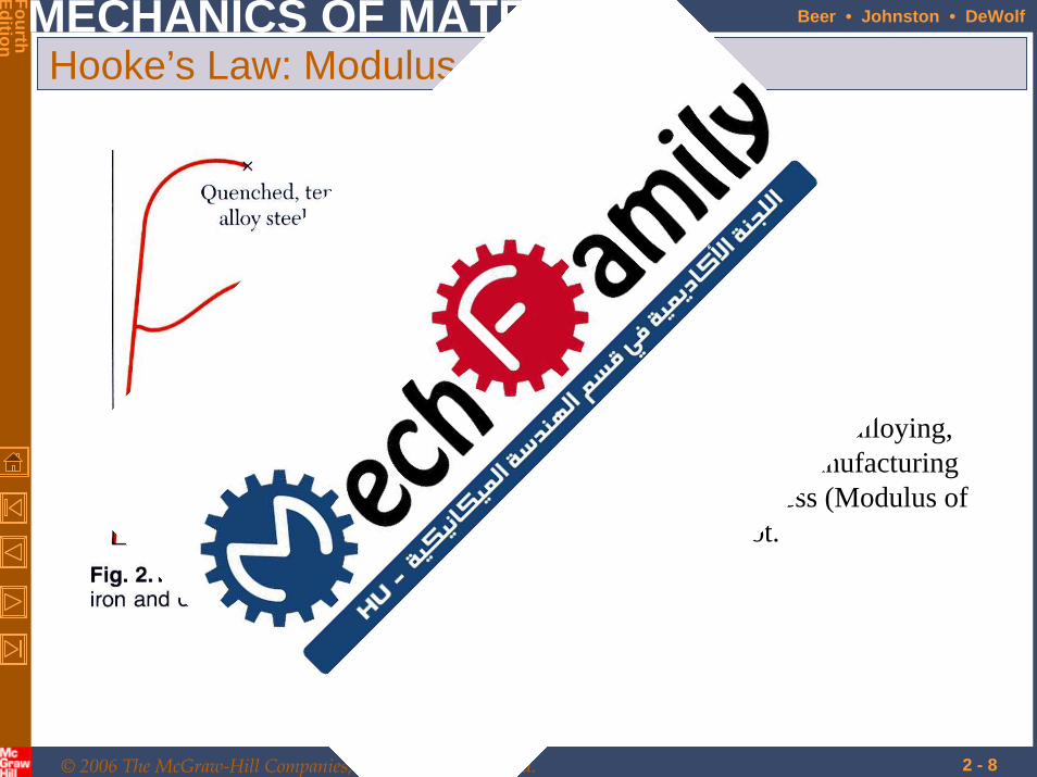
Hooke’s Law: Modulus of Elasticity
• Below the yield stress
Elasticity of Modulus or Modulus Youngs=
=E
Eεσ
• Strength is affected by alloying, heat treating, and manufacturing process but stiffness (Modulus of Elasticity) is not.

© 2006 The McGraw-Hill Companies, Inc. All rights reserved.
MECHANICS OF MATERIALS
FourthEdition
Beer • Johnston • DeWolf
2 - 9
Elastic vs. Plastic Behavior
• If the strain disappears when the stress is removed, the material is said to behave elastically.
• When the strain does not return to zero after the stress is removed, the material is said to behave plastically.
• The largest stress for which this occurs is called the elastic limit.
© 2006 The McGraw-Hill Companies, Inc. All rights reserved.
MECHANICS OF MATERIALS
FourthEdition
Beer • Johnston • DeWolf
2 - 10
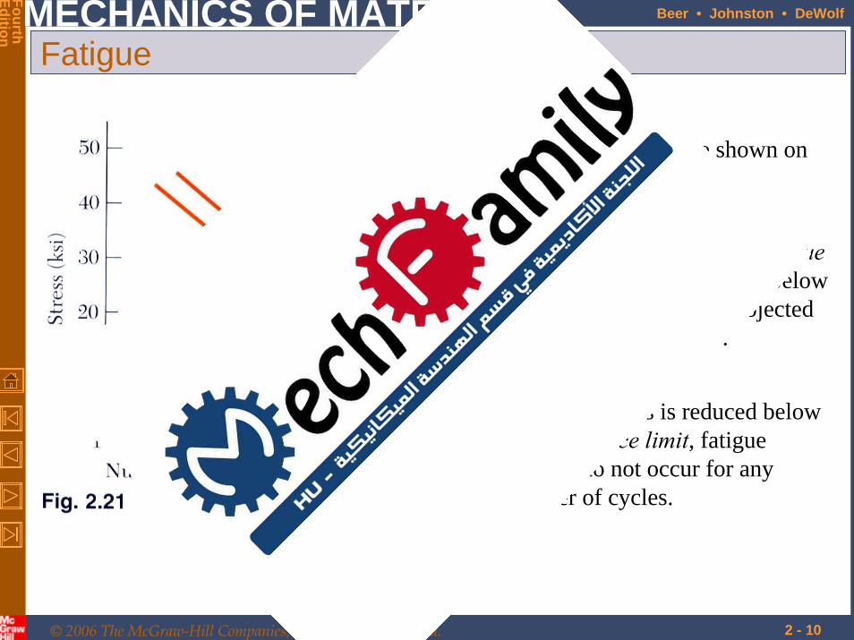
Fatigue
• Fatigue properties are shown on S-N diagrams.
• When the stress is reduced below the endurance limit, fatigue failures do not occur for any number of cycles.
• A member may fail due to fatigueat stress levels significantly below the ultimate strength if subjected to many loading cycles.
© 2006 The McGraw-Hill Companies, Inc. All rights reserved.
MECHANICS OF MATERIALS
FourthEdition
Beer • Johnston • DeWolf
2 - 11
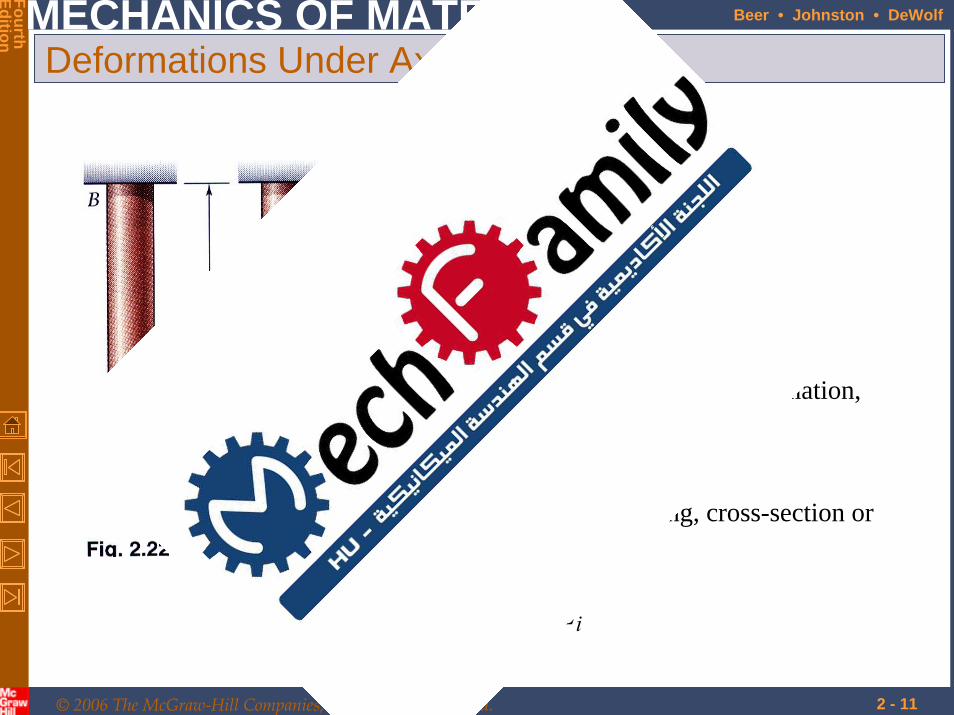
Deformations Under Axial Loading
AEP
EE ===
σεεσ
• From Hooke’s Law:
• From the definition of strain:
Lδε =
• Equating and solving for the deformation,
AEPL
=δ
• With variations in loading, cross-section or material properties,
∑=i ii
iiEALPδ
© 2006 The McGraw-Hill Companies, Inc. All rights reserved.
MECHANICS OF MATERIALS
FourthEdition
Beer • Johnston • DeWolf
2 - 12
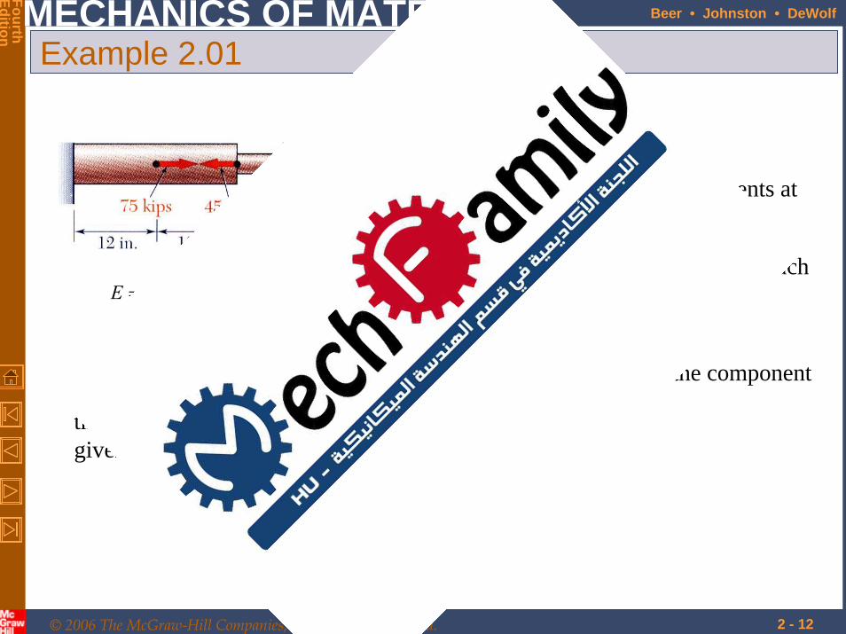
Example 2.01
in.618.0 in. 07.1
psi1029 6
==
×= −
dD
E
SOLUTION:• Divide the rod into components at
the load application points.
• Apply a free-body analysis on each component to determine the internal force
• Evaluate the total of the component deflections.Determine the deformation of
the steel rod shown under the given loads.
© 2006 The McGraw-Hill Companies, Inc. All rights reserved.
MECHANICS OF MATERIALS
FourthEdition
Beer • Johnston • DeWolf
2 - 13
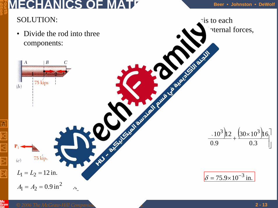
SOLUTION:
• Divide the rod into three components:
• Apply free-body analysis to each component to determine internal forces,
lb1030
lb1015
lb1060
33
32
31
×=
×−=
×=
P
P
P
• Evaluate total deflection,
( ) ( ) ( )
in.109.75
3.0161030
9.0121015
9.0121060
10291
1
3
333
6
3
33
2
22
1
11
−×=
⎥⎥⎦
⎤
⎢⎢⎣
⎡ ×+
×−+
×
×=
⎟⎟⎠
⎞⎜⎜⎝
⎛++=∑=
ALP
ALP
ALP
EEALP
i ii
iiδ
in.109.75 3−×=δ2
21
21
in 9.0
in. 12
==
==
AA
LL
23
3
in 3.0
in. 16
=
=
A
L
© 2006 The McGraw-Hill Companies, Inc. All rights reserved.
MECHANICS OF MATERIALS
FourthEdition
Beer • Johnston • DeWolf
2 - 14
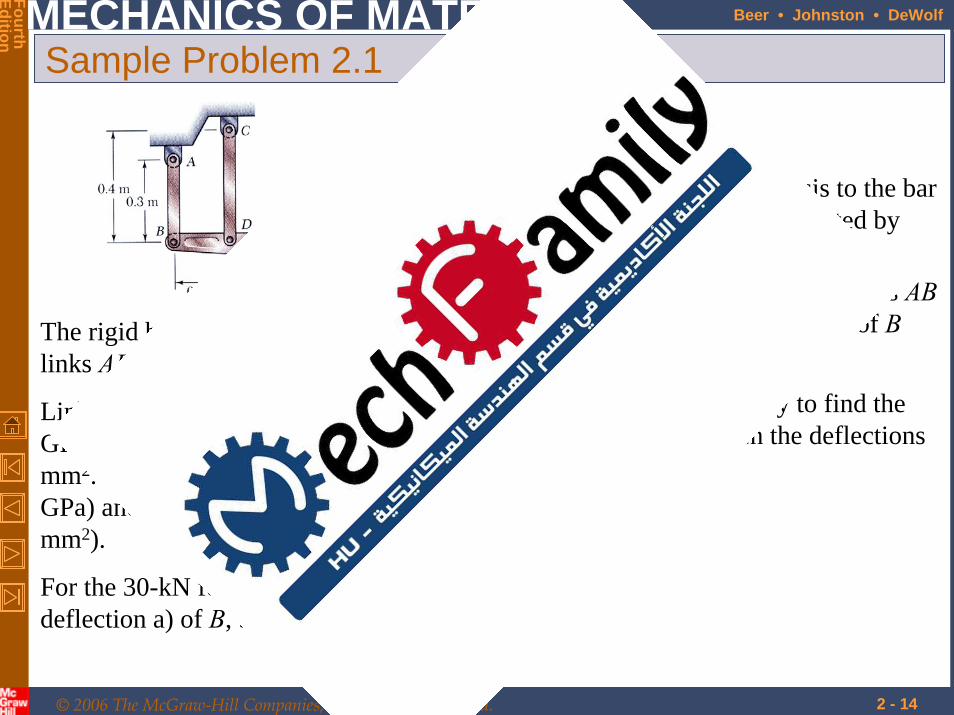
Sample Problem 2.1
The rigid bar BDE is supported by two links AB and CD.
Link AB is made of aluminum (E = 70 GPa) and has a cross-sectional area of 500 mm2. Link CD is made of steel (E = 200 GPa) and has a cross-sectional area of (600 mm2).
For the 30-kN force shown, determine the deflection a) of B, b) of D, and c) of E.
SOLUTION:
• Apply a free-body analysis to the bar BDE to find the forces exerted by links AB and DC.
• Evaluate the deformation of links ABand DC or the displacements of Band D.
• Work out the geometry to find the deflection at E given the deflections at B and D.

© 2006 The McGraw-Hill Companies, Inc. All rights reserved.
MECHANICS OF MATERIALS
FourthEdition
Beer • Johnston • DeWolf
2 - 15
Sample Problem 2.1Displacement of B:
( )( )( )( )
m10514
Pa1070m10500m3.0N1060
6
926-
3
−×−=
××
×−=
=AEPL
Bδ
↑= mm 514.0BδDisplacement of D:
( )( )( )( )
m10300
Pa10200m10600m4.0N1090
6
926-
3
−×=
××
×=
=AEPL
Dδ
↓= mm 300.0Dδ
Free body: Bar BDE
( )
( )ncompressioF
F
tensionF
F
M
AB
AB
CD
CD
B
kN60
m2.0m4.0kN300
0M
kN90
m2.0m6.0kN300
0
D
−=
×−×−=
=
+=
×+×−=
=
∑
∑
SOLUTION:

© 2006 The McGraw-Hill Companies, Inc. All rights reserved.
MECHANICS OF MATERIALS
FourthEdition
Beer • Johnston • DeWolf
2 - 16
Sample Problem 2.1
Displacement of D:
( )
mm 7.73
mm 200mm 0.300mm 514.0
=
−=
=′′
xx
xHDBH
DDBB
↓= mm 928.1Eδ
( )
mm 928.1mm 7.73
mm7.73400mm 300.0
=
+=
=′′
E
E
HDHE
DDEE
δ
δ
© 2006 The McGraw-Hill Companies, Inc. All rights reserved.
MECHANICS OF MATERIALS
FourthEdition
Beer • Johnston • DeWolf
2 - 17
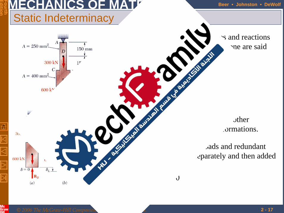
Static Indeterminacy• Structures for which internal forces and reactions
cannot be determined from statics alone are said to be statically indeterminate.
0=+= RL δδδ
• Deformations due to actual loads and redundant reactions are determined separately and then added or superposed.
• Redundant reactions are replaced with unknown loads which along with the other loads must produce compatible deformations.
• A structure will be statically indeterminate whenever it is held by more supports than are required to maintain its equilibrium.

© 2006 The McGraw-Hill Companies, Inc. All rights reserved.
MECHANICS OF MATERIALS
FourthEdition
Beer • Johnston • DeWolf
2 - 18
Example 2.04Determine the reactions at A and B for the steel bar and loading shown, assuming a close fit at both supports before the loads are applied.
• Solve for the reaction at A due to applied loads and the reaction found at B.
• Require that the displacements due to the loads and due to the redundant reaction be compatible, i.e., require that their sum be zero.
• Solve for the displacement at B due to the redundant reaction at B.
SOLUTION:
• Consider the reaction at B as redundant, release the bar from that support, and solve for the displacement at B due to the applied loads.

© 2006 The McGraw-Hill Companies, Inc. All rights reserved.
MECHANICS OF MATERIALS
FourthEdition
Beer • Johnston • DeWolf
2 - 19
SOLUTION:• Solve for the displacement at B due to the applied
loads with the redundant constraint released,
EEALP
LLLL
AAAA
PPPP
i ii
ii9
L
4321
2643
2621
34
3321
10125.1
m 150.0
m10250m10400
N10900N106000
×=∑=
====
×==×==
×=×===
−−
δ
• Solve for the displacement at B due to the redundant constraint,
( )∑
×−==
==
×=×=
−==
−−
i
B
ii
iiR
B
ER
EALPδ
LL
AA
RPP
3
21
262
261
21
1095.1
m 300.0
m10250m10400
Example 2.04

© 2006 The McGraw-Hill Companies, Inc. All rights reserved.
MECHANICS OF MATERIALS
FourthEdition
Beer • Johnston • DeWolf
2 - 20
Example 2.04
• Require that the displacements due to the loads and due to the redundant reaction be compatible,
( )
kN 577N10577
01095.110125.1
0
3
39
=×=
=×
−×
=
=+=
B
B
RL
R
ER
Eδ
δδδ
• Find the reaction at A due to the loads and the reaction at B
kN323
kN577kN600kN 3000
=
∑ +−−==
A
Ay
R
RF
kN577
kN323
=
=
B
A
R
R
© 2006 The McGraw-Hill Companies, Inc. All rights reserved.
MECHANICS OF MATERIALS
FourthEdition
Beer • Johnston • DeWolf
2 - 21
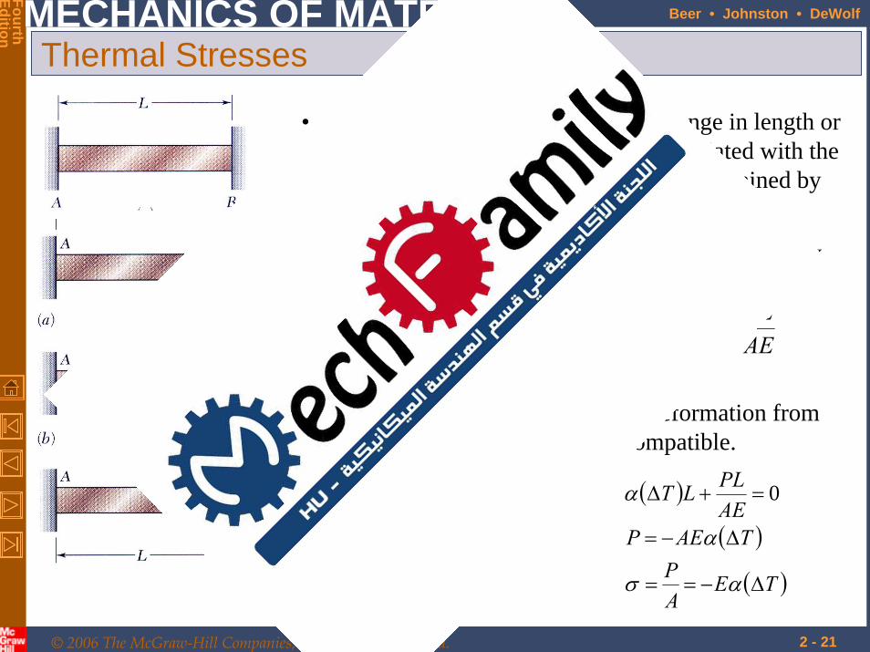
Thermal Stresses
• A temperature change results in a change in length or thermal strain. There is no stress associated with the thermal strain unless the elongation is restrained by the supports.
( )coef.expansion thermal=
=∆=
α
δαδAEPLLT PT
• Treat the additional support as redundant and apply the principle of superposition.
0=+= PT δδδ
• The thermal deformation and the deformation from the redundant support must be compatible.
( )
( )
( )TEAP
TAEPAEPLLT
∆−==
∆−=
=+∆
ασ
α
α 0