Four Output Relays/ 3-15 PSI Pneumatic Interface … Output Relays/ 3-15 PSI Pneumatic Interface...
28
Four Output Relays/ 3-15 PSI Pneumatic Interface Expansion Board Catalog No. EXB004A01 Installation and Operating Manual 6/96 MN1315
-
Upload
truongthien -
Category
Documents
-
view
225 -
download
0
Transcript of Four Output Relays/ 3-15 PSI Pneumatic Interface … Output Relays/ 3-15 PSI Pneumatic Interface...
Four Output Relays/3-15 PSI Pneumatic Interface
Expansion Board
Catalog No. EXB004A01
Installation and Operating Manual
6/96 MN1315
Table of Contents
Table of Contents i
Section 1General Information 1-1. . . . . . . . . . . . . . . . . . . . . . . . . . . . .
Introduction 1-1. . . . . . . . . . . . . . . . . . . . . . . . . . . . . . . . . . . . Limited Warranty 1-2. . . . . . . . . . . . . . . . . . . . . . . . . . . . . . . Safety Notice 1-3. . . . . . . . . . . . . . . . . . . . . . . . . . . . . . . . . .
Precautions 1-3. . . . . . . . . . . . . . . . . . . . . . . . . . . . . . . . . Section 2Expansion Board Description 2-1. . . . . . . . . . . . . . . . . . . .
Introduction 2-1. . . . . . . . . . . . . . . . . . . . . . . . . . . . . . . . . . . . Relay Output Operation 2-1. . . . . . . . . . . . . . . . . . . . . . . . . 3-15 PSI Pneumatic Interface Operation 2-2. . . . . . . . . . .
Section 3Installation 3-1. . . . . . . . . . . . . . . . . . . . . . . . . . . . . . . . . . . . . .
Board Installation 3-1. . . . . . . . . . . . . . . . . . . . . . . . . . . . . . . 1-15HP Size A and B Controls 3-2. . . . . . . . . . . . . . . . . . .
Single Expansion Board Installation 3-2. . . . . . . . . . . . . Dual Expansion Board Installation 3-4. . . . . . . . . . . . . .
15HP Size C and Larger AC Controls 3-6. . . . . . . . . . . . . Single Expansion Board Installation 3-6. . . . . . . . . . . . . Dual Expansion Board Installation 3-8. . . . . . . . . . . . . .
SCR DC Controls 3-10. . . . . . . . . . . . . . . . . . . . . . . . . . . . . . Single Expansion Board Installation 3-10. . . . . . . . . . . . . Dual Expansion Board Installation 3-11. . . . . . . . . . . . . .
Section 4Hardware Setup 4-1. . . . . . . . . . . . . . . . . . . . . . . . . . . . . . . . .
Introduction 4-1. . . . . . . . . . . . . . . . . . . . . . . . . . . . . . . . . . . . 3-15 PSI Pneumatic Interface Operation 4-1. . . . . . . . . . . Relay Output Operation 4-2. . . . . . . . . . . . . . . . . . . . . . . . .

ii Table of Contents
Section 1General Information
General Information 1-1
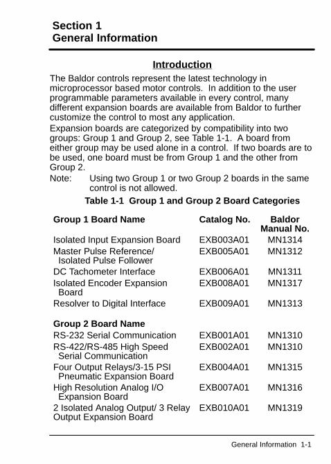
IntroductionThe Baldor controls represent the latest technology inmicroprocessor based motor controls. In addition to the userprogrammable parameters available in every control, manydifferent expansion boards are available from Baldor to furthercustomize the control to most any application.Expansion boards are categorized by compatibility into twogroups: Group 1 and Group 2, see Table 1-1. A board fromeither group may be used alone in a control. If two boards are tobe used, one board must be from Group 1 and the other fromGroup 2.Note: Using two Group 1 or two Group 2 boards in the same
control is not allowed.Table 1-1 Group 1 and Group 2 Board Categories
Group 1 Board Name Catalog No. BaldorManual No.
Isolated Input Expansion Board EXB003A01 MN1314Master Pulse Reference/ Isolated Pulse Follower
EXB005A01 MN1312
DC Tachometer Interface EXB006A01 MN1311Isolated Encoder Expansion Board
EXB008A01 MN1317
Resolver to Digital Interface EXB009A01 MN1313
Group 2 Board NameRS-232 Serial Communication EXB001A01 MN1310RS-422/RS-485 High Speed Serial Communication
EXB002A01 MN1310
Four Output Relays/3-15 PSI Pneumatic Expansion Board
EXB004A01 MN1315
High Resolution Analog I/O Expansion Board
EXB007A01 MN1316
2 Isolated Analog Output/ 3 RelayOutput Expansion Board
EXB010A01 MN1319
1-2 General Information
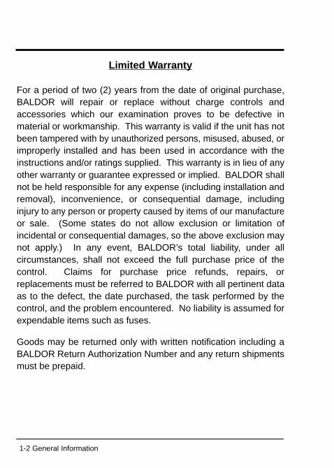
Limited Warranty
For a period of two (2) years from the date of original purchase,BALDOR will repair or replace without charge controls andaccessories which our examination proves to be defective inmaterial or workmanship. This warranty is valid if the unit has notbeen tampered with by unauthorized persons, misused, abused, orimproperly installed and has been used in accordance with theinstructions and/or ratings supplied. This warranty is in lieu of anyother warranty or guarantee expressed or implied. BALDOR shallnot be held responsible for any expense (including installation andremoval), inconvenience, or consequential damage, includinginjury to any person or property caused by items of our manufactureor sale. (Some states do not allow exclusion or limitation ofincidental or consequential damages, so the above exclusion maynot apply.) In any event, BALDOR’s total liability, under allcircumstances, shall not exceed the full purchase price of thecontrol. Claims for purchase price refunds, repairs, orreplacements must be referred to BALDOR with all pertinent dataas to the defect, the date purchased, the task performed by thecontrol, and the problem encountered. No liability is assumed forexpendable items such as fuses.
Goods may be returned only with written notification including aBALDOR Return Authorization Number and any return shipmentsmust be prepaid.
General Information 1-3
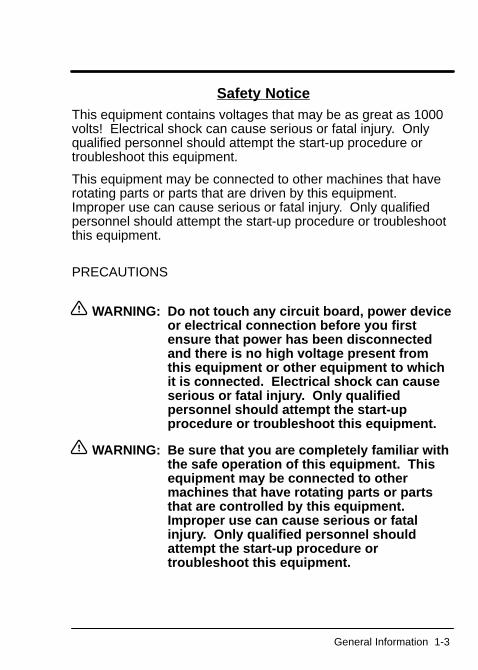
Safety NoticeThis equipment contains voltages that may be as great as 1000volts! Electrical shock can cause serious or fatal injury. Onlyqualified personnel should attempt the start-up procedure ortroubleshoot this equipment.
This equipment may be connected to other machines that haverotating parts or parts that are driven by this equipment.Improper use can cause serious or fatal injury. Only qualifiedpersonnel should attempt the start-up procedure or troubleshootthis equipment.
PRECAUTIONS
WARNING: Do not touch any circuit board, power deviceor electrical connection before you firstensure that power has been disconnectedand there is no high voltage present fromthis equipment or other equipment to whichit is connected. Electrical shock can causeserious or fatal injury . Only qualifiedpersonnel should attempt the start-upprocedure or troubleshoot this equipment.
WARNING: Be sure that you are completely familiar withthe safe operation of this equipment. Thisequipment may be connected to othermachines that have rotating parts or partsthat are controlled by this equipment.Improper use can cause serious or fatalinjury. Only qualified personnel shouldattempt the start-up procedure ortroubleshoot this equipment.
1-4 General Information
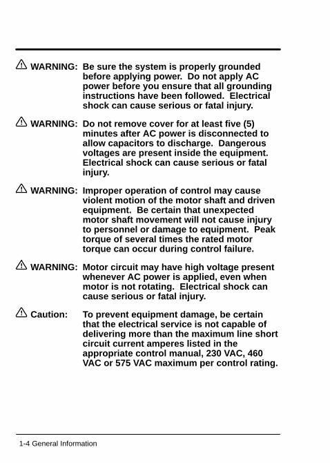
WARNING: Be sure the system is properly groundedbefore applying power. Do not apply ACpower before you ensure that all groundinginstructions have been followed. Electricalshock can cause serious or fatal injury .
WARNING: Do not remove cover for at least five (5)minutes after AC power is disconnected toallow capacitors to discharge. Dangerousvoltages are present inside the equipment.Electrical shock can cause serious or fatalinjury.
WARNING: Improper operation of control may causeviolent motion of the motor shaft and drivenequipment. Be certain that unexpectedmotor shaft movement will not cause injuryto personnel or damage to equipment. Peaktorque of several times the rated motortorque can occur during control failure.
WARNING: Motor circuit may have high voltage presentwhenever AC power is applied, even whenmotor is not rotating. Electrical shock cancause serious or fatal injury .
Caution: T o prevent equipment damage, be certainthat the electrical service is not capable ofdelivering more than the maximum line shortcircuit current amperes listed in theappropriate control manual, 230 V AC, 460VAC or 575 VAC maximum per control rating.
Section 2Expansion Board Description
Description 2-1
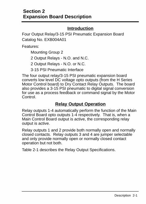
IntroductionFour Output Relay/3-15 PSI Pneumatic Expansion BoardCatalog No. EXB004A01
Features:Mounting Group 22 Output Relays - N.O. and N.C.2 Output Relays - N.O. or N.C.3-15 PSI Pneumatic Interface
The four output relay/3-15 PSI pneumatic expansion boardconverts low level DC voltage opto outputs (from the H SeriesMotor Control board) to Dry Contact Relay Outputs. The boardalso provides a 3-15 PSI pneumatic to digital signal conversionfor use as a process feedback or command signal by the MotorControl.
Relay Output OperationRelay outputs 1-4 automatically perform the function of the MainControl Board opto outputs 1-4 respectively. That is, when aMain Control Board output is active, the corresponding relayoutput is active.
Relay outputs 1 and 2 provide both normally open and normallyclosed contacts. Relay outputs 3 and 4 are jumper selectableand only provide normally open or normally closed contactoperation but not both.
Table 2-1 describes the Relay Output Specifications.
2-2 Description
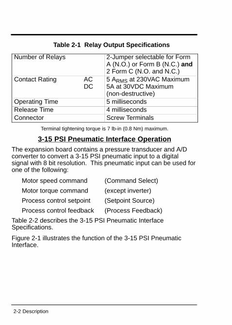
Table 2-1 Relay Output Specifications
Number of Relays 2-Jumper selectable for FormA (N.O.) or Form B (N.C.) and 2 Form C (N.O. and N.C.)
Contact Rating ACDC
5 ARMS at 230VAC Maximum5A at 30VDC Maximum(non-destructive)
Operating Time 5 millisecondsRelease Time 4 millisecondsConnector Screw Terminals
Terminal tightening torque is 7 lb-in (0.8 Nm) maximum.
3-15 PSI Pneumatic Interface OperationThe expansion board contains a pressure transducer and A/Dconverter to convert a 3-15 PSI pneumatic input to a digitalsignal with 8 bit resolution. This pneumatic input can be used forone of the following:
Motor speed command (Command Select)
Motor torque command (except inverter)
Process control setpoint (Setpoint Source)
Process control feedback (Process Feedback)
Table 2-2 describes the 3-15 PSI Pneumatic InterfaceSpecifications.
Figure 2-1 illustrates the function of the 3-15 PSI PneumaticInterface.
Description 2-3
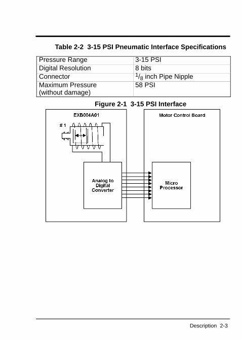
Table 2-2 3-15 PSI Pneumatic Interface Specifications
Pressure Range 3-15 PSIDigital Resolution 8 bitsConnector 1/8 inch Pipe NippleMaximum Pressure (without damage)
58 PSI
Figure 2-1 3-15 PSI Interface

2-4 Description
Section 3Installation
Installation 3-1
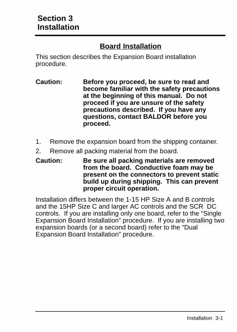
Board InstallationThis section describes the Expansion Board installationprocedure.
Caution: Before you proceed, be sure to read andbecome familiar with the safety precautionsat the beginning of this manual. Do notproceed if you are unsure of the safetyprecautions described. If you have anyquestions, contact BALDOR before youproceed.
1. Remove the expansion board from the shipping container.2. Remove all packing material from the board.Caution: Be sure all packing materials are removed
from the board. Conductive foam may bepresent on the connectors to prevent staticbuild up during shipping. This can preventproper circuit operation.
Installation differs between the 1-15 HP Size A and B controlsand the 15HP Size C and larger AC controls and the SCR DCcontrols. If you are installing only one board, refer to the “SingleExpansion Board Installation” procedure. If you are installing twoexpansion boards (or a second board) refer to the “DualExpansion Board Installation” procedure.
3-2 Installation
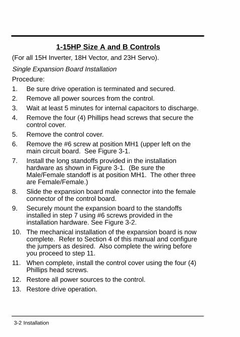
1-15HP Size A and B Controls(For all 15H Inverter, 18H Vector, and 23H Servo).
Single Expansion Board Installation
Procedure:1. Be sure drive operation is terminated and secured.2. Remove all power sources from the control.3. Wait at least 5 minutes for internal capacitors to discharge.4. Remove the four (4) Phillips head screws that secure the
control cover.5. Remove the control cover.6. Remove the #6 screw at position MH1 (upper left on the
main circuit board. See Figure 3-1.7. Install the long standoffs provided in the installation
hardware as shown in Figure 3-1. (Be sure theMale/Female standoff is at position MH1. The other threeare Female/Female.)
8. Slide the expansion board male connector into the femaleconnector of the control board.
9. Securely mount the expansion board to the standoffsinstalled in step 7 using #6 screws provided in theinstallation hardware. See Figure 3-2.
10. The mechanical installation of the expansion board is nowcomplete. Refer to Section 4 of this manual and configurethe jumpers as desired. Also complete the wiring beforeyou proceed to step 11.
11. When complete, install the control cover using the four (4)Phillips head screws.
12. Restore all power sources to the control.13. Restore drive operation.
Installation 3-3
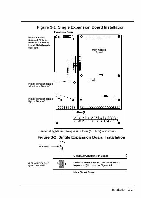
Figure 3-1 Single Expansion Board Installation
Remove screw(Labeled MH1 inMain PCB Screen).Install Male/FemaleStandoff.
Install Female/FemaleAluminum Standoff.
Install Female/FemaleNylon Standoff.
Main ControlBoard
Expansion Board
Terminal tightening torque is 7 lb-in (0.8 Nm) maximum.
Figure 3-2 Single Expansion Board Installation
#6 Screw
Long Aluminum orNylon Standoff
Group 1 or 2 Expansion Board
Female/Female shown. Use Male/Femalein place of (MH1) screw Figure 3-1.
Main Circuit Board
3-4 Installation
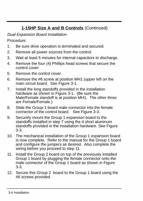
1-15HP Size A and B Controls (Continued)
Dual Expansion Board Installation
Procedure:1. Be sure drive operation is terminated and secured.2. Remove all power sources from the control.3. Wait at least 5 minutes for internal capacitors to discharge.4. Remove the four (4) Phillips head screws that secure the
control cover.5. Remove the control cover.6. Remove the #6 screw at position MH1 (upper left on the
main circuit board. See Figure 3-1.7. Install the long standoffs provided in the installation
hardware as shown in Figure 3-1. (Be sure theMale/Female standoff is at position MH1. The other threeare Female/Female.)
8. Slide the Group 1 board male connector into the femaleconnector of the control board. See Figure 3-3.
9. Securely mount the Group 1 expansion board to thestandoffs installed in step 7 using the 4 short aluminumstandoffs provided in the installation hardware. See Figure3-3.
10. The mechanical installation of the Group 1 expansion boardis now complete. Refer to the manual for the Group 1 boardand configure the jumpers as desired. Also complete thewiring before you proceed to step 11.
11. Install the Group 2 board on top of the previously installedGroup 1 board by plugging the female connector onto themale connector of the Group 1 board as shown in Figure3-3.
12. Secure this Group 2 board to the Group 1 board using the#6 screws provided.
Installation 3-5
1-15HP Size A and B ControlsDual Expansion Board Installation (Continued)
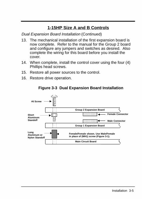
13. The mechanical installation of the first expansion board isnow complete. Refer to the manual for the Group 2 boardand configure any jumpers and switches as desired. Alsocomplete the wiring for this board before you install thecover.
14. When complete, install the control cover using the four (4)Phillips head screws.
15. Restore all power sources to the control.16. Restore drive operation.
Figure 3-3 Dual Expansion Board Installation
#6 Screw
Female Connector
Male Connector
Group 2 Expansion Board
Group 1 Expansion Board
Main Circuit Board
Female/Female shown. Use Male/Femalein place of (MH1) screw (Figure 3-1).
ShortAluminumStandoff
LongAluminum or Nylon Standoff
3-6 Installation
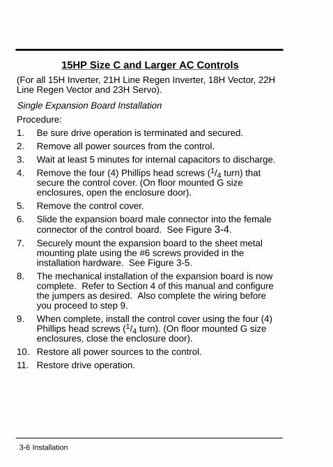
15HP Size C and Larger AC Controls(For all 15H Inverter, 21H Line Regen Inverter, 18H Vector, 22HLine Regen Vector and 23H Servo).
Single Expansion Board Installation
Procedure:1. Be sure drive operation is terminated and secured.2. Remove all power sources from the control.3. Wait at least 5 minutes for internal capacitors to discharge.4. Remove the four (4) Phillips head screws (1/4 turn) that
secure the control cover. (On floor mounted G sizeenclosures, open the enclosure door).
5. Remove the control cover.6. Slide the expansion board male connector into the female
connector of the control board. See Figure 3-4.
7. Securely mount the expansion board to the sheet metalmounting plate using the #6 screws provided in theinstallation hardware. See Figure 3-5.
8. The mechanical installation of the expansion board is nowcomplete. Refer to Section 4 of this manual and configurethe jumpers as desired. Also complete the wiring beforeyou proceed to step 9.
9. When complete, install the control cover using the four (4)Phillips head screws (1/4 turn). (On floor mounted G sizeenclosures, close the enclosure door).
10. Restore all power sources to the control.11. Restore drive operation.
Installation 3-7
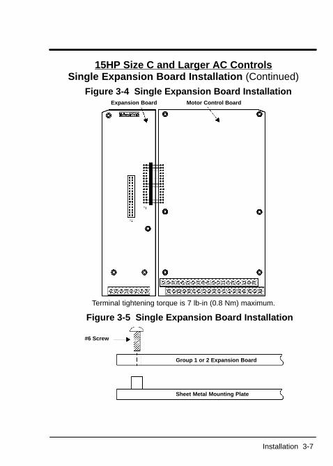
15HP Size C and Larger AC ControlsSingle Expansion Board Installation (Continued)
Figure 3-4 Single Expansion Board Installation Expansion Board Motor Control Board
Terminal tightening torque is 7 lb-in (0.8 Nm) maximum.
Figure 3-5 Single Expansion Board Installation
#6 Screw
Group 1 or 2 Expansion Board
Sheet Metal Mounting Plate
3-8 Installation
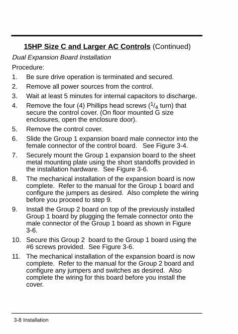
15HP Size C and Larger AC Controls (Continued)
Dual Expansion Board Installation
Procedure:1. Be sure drive operation is terminated and secured.2. Remove all power sources from the control.3. Wait at least 5 minutes for internal capacitors to discharge.4. Remove the four (4) Phillips head screws (1/4 turn) that
secure the control cover. (On floor mounted G sizeenclosures, open the enclosure door).
5. Remove the control cover.6. Slide the Group 1 expansion board male connector into the
female connector of the control board. See Figure 3-4.7. Securely mount the Group 1 expansion board to the sheet
metal mounting plate using the short standoffs provided inthe installation hardware. See Figure 3-6.
8. The mechanical installation of the expansion board is nowcomplete. Refer to the manual for the Group 1 board andconfigure the jumpers as desired. Also complete the wiringbefore you proceed to step 9.
9. Install the Group 2 board on top of the previously installedGroup 1 board by plugging the female connector onto themale connector of the Group 1 board as shown in Figure3-6.
10. Secure this Group 2 board to the Group 1 board using the#6 screws provided. See Figure 3-6.
11. The mechanical installation of the expansion board is nowcomplete. Refer to the manual for the Group 2 board andconfigure any jumpers and switches as desired. Alsocomplete the wiring for this board before you install thecover.
Installation 3-9
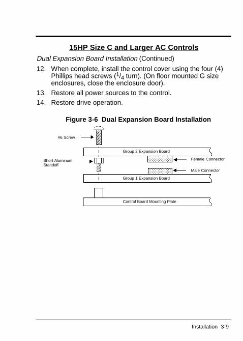
15HP Size C and Larger AC ControlsDual Expansion Board Installation (Continued)
12. When complete, install the control cover using the four (4)Phillips head screws (1/4 turn). (On floor mounted G sizeenclosures, close the enclosure door).
13. Restore all power sources to the control.14. Restore drive operation.
Figure 3-6 Dual Expansion Board Installation
#6 Screw
Short AluminumStandoff
Group 2 Expansion Board
Group 1 Expansion Board
Control Board Mounting Plate
Female Connector
Male Connector
3-10 Installation
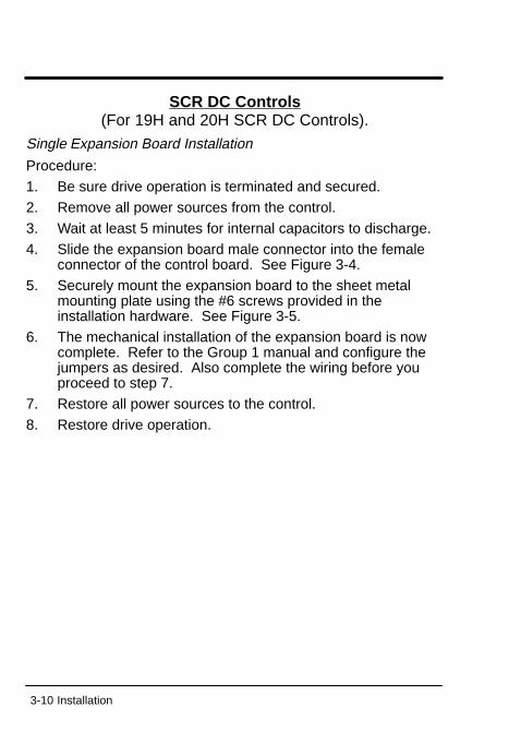
SCR DC Controls(For 19H and 20H SCR DC Controls).
Single Expansion Board Installation
Procedure:1. Be sure drive operation is terminated and secured.2. Remove all power sources from the control.3. Wait at least 5 minutes for internal capacitors to discharge.4. Slide the expansion board male connector into the female
connector of the control board. See Figure 3-4.5. Securely mount the expansion board to the sheet metal
mounting plate using the #6 screws provided in theinstallation hardware. See Figure 3-5.
6. The mechanical installation of the expansion board is nowcomplete. Refer to the Group 1 manual and configure thejumpers as desired. Also complete the wiring before youproceed to step 7.
7. Restore all power sources to the control.8. Restore drive operation.
Installation 3-11
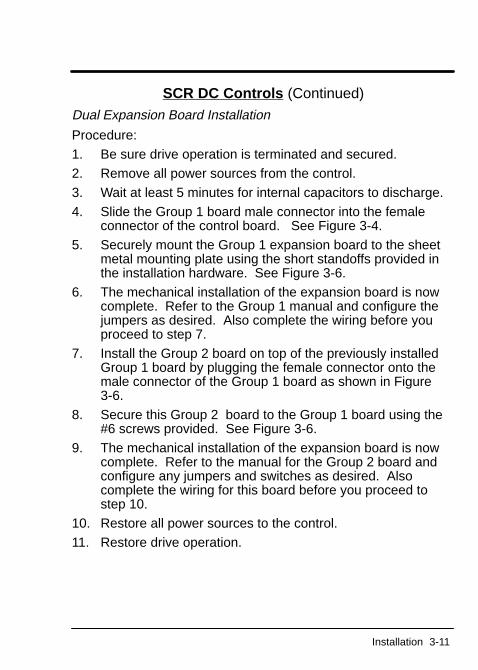
SCR DC Controls (Continued)
Dual Expansion Board Installation
Procedure:1. Be sure drive operation is terminated and secured.2. Remove all power sources from the control.3. Wait at least 5 minutes for internal capacitors to discharge.4. Slide the Group 1 board male connector into the female
connector of the control board. See Figure 3-4.5. Securely mount the Group 1 expansion board to the sheet
metal mounting plate using the short standoffs provided inthe installation hardware. See Figure 3-6.
6. The mechanical installation of the expansion board is nowcomplete. Refer to the Group 1 manual and configure thejumpers as desired. Also complete the wiring before youproceed to step 7.
7. Install the Group 2 board on top of the previously installedGroup 1 board by plugging the female connector onto themale connector of the Group 1 board as shown in Figure3-6.
8. Secure this Group 2 board to the Group 1 board using the#6 screws provided. See Figure 3-6.
9. The mechanical installation of the expansion board is nowcomplete. Refer to the manual for the Group 2 board andconfigure any jumpers and switches as desired. Alsocomplete the wiring for this board before you proceed tostep 10.
10. Restore all power sources to the control.11. Restore drive operation.

3-12 Installation
Section 4Hardware Setup
Setup 4-1
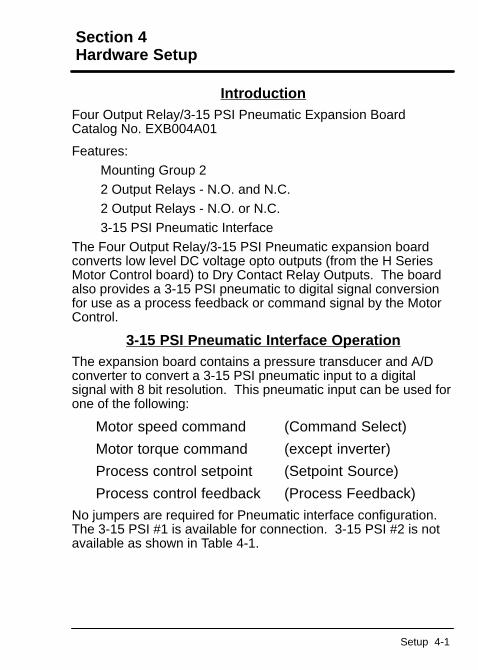
IntroductionFour Output Relay/3-15 PSI Pneumatic Expansion BoardCatalog No. EXB004A01
Features:Mounting Group 22 Output Relays - N.O. and N.C.2 Output Relays - N.O. or N.C.3-15 PSI Pneumatic Interface
The Four Output Relay/3-15 PSI Pneumatic expansion boardconverts low level DC voltage opto outputs (from the H SeriesMotor Control board) to Dry Contact Relay Outputs. The boardalso provides a 3-15 PSI pneumatic to digital signal conversionfor use as a process feedback or command signal by the MotorControl.
3-15 PSI Pneumatic Interface OperationThe expansion board contains a pressure transducer and A/Dconverter to convert a 3-15 PSI pneumatic input to a digitalsignal with 8 bit resolution. This pneumatic input can be used forone of the following:
Motor speed command (Command Select)
Motor torque command (except inverter)
Process control setpoint (Setpoint Source)
Process control feedback (Process Feedback)
No jumpers are required for Pneumatic interface configuration.The 3-15 PSI #1 is available for connection. 3-15 PSI #2 is notavailable as shown in Table 4-1.
4-2 Setup
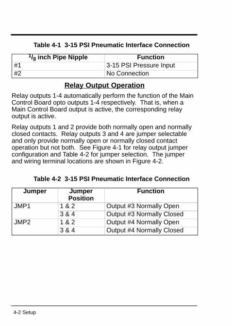
Table 4-1 3-15 PSI Pneumatic Interface Connection
1/8 inch Pipe Nipple Function#1 3-15 PSI Pressure Input#2 No Connection
Relay Output OperationRelay outputs 1-4 automatically perform the function of the MainControl Board opto outputs 1-4 respectively. That is, when aMain Control Board output is active, the corresponding relayoutput is active.
Relay outputs 1 and 2 provide both normally open and normallyclosed contacts. Relay outputs 3 and 4 are jumper selectableand only provide normally open or normally closed contactoperation but not both. See Figure 4-1 for relay output jumperconfiguration and Table 4-2 for jumper selection. The jumperand wiring terminal locations are shown in Figure 4-2.
Table 4-2 3-15 PSI Pneumatic Interface Connection
Jumper JumperPosition
Function
JMP1 1 & 2 Output #3 Normally Open3 & 4 Output #3 Normally Closed
JMP2 1 & 2 Output #4 Normally Open3 & 4 Output #4 Normally Closed
Setup 4-3
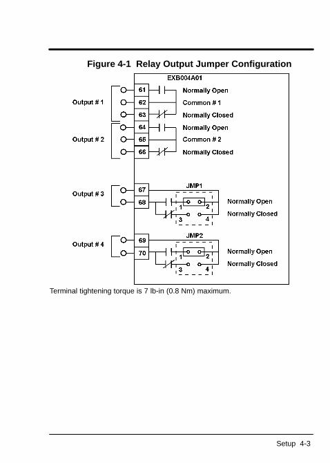
Figure 4-1 Relay Output Jumper Configuration
Terminal tightening torque is 7 lb-in (0.8 Nm) maximum.
4-4 Setup
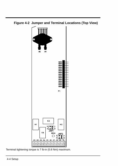
Figure 4-2 Jumper and T erminal Locations (T op View)
Terminal tightening torque is 7 lb-in (0.8 Nm) maximum.

BALDOR ELECTRIC COMPANYP.O. Box 2400
Fort Smith, AR 72902–2400(501) 646–4711
Fax (501) 648–5792
Baldor Electric Company Printed in USAMN1315 6/96 C&J2500