Fortron PPS Material Spec
59
Fortron ® Polyphenylene sulphide (PPS) Fortron ® Polyphenylene sulphide (PPS) • very good chemical resistance • inherently flame retardant • high hardness and rigidity • low creep • continuous service temperature up to +240 °C
-
Upload
ranjanganapathi -
Category
Documents
-
view
567 -
download
26
Transcript of Fortron PPS Material Spec

Fort
ron
®Po
lyph
enyl
ene
sulp
hide
(PPS
)Fortron®
Polyphenylene sulphide (PPS)
• very good chemicalresistance
• inherently flameretardant
• high hardness andrigidity
• low creep• continuous service
temperatureup to +240 °C

Fortron®
Polyphenylene sulphide (PPS)
Contents1. Introduction 2
1.1 Typical Applications 2
2. Product line 4
2.1 Grades 42.2 Colorability 52.3 Packaging 62.4 Quality assurance 6
3. Properties 7
3.1 Physical properties 73.2 Mechanical properties 73.3 Thermal 123.4 Electrical 153.5 Surface properties 16
4. Environmental resistance 17
4.1 Thermal resistance 174.2 Moisture resistance 184.3 Chemical resistance 184.4 UV resistance 194.5 Permeability 19
5. Specifications and standards 21
5.1 Automotive specifications 215.2 Assesment under food legislation 215.3 Pharmaceutical/medical applications 225.4 Products for medical and pharmaceutical applications 22
6. General processing considerations 23
6.1 Safety 236.2 Start up and shut down 236.3 Drying considerations 236.4 Purging 24

1
Fortron®
Polyphenylene sulphide (PPS)
1
2
3
4
5
6
7
8
9
10
11
12
7. Injection molding 24
7.1 Equipment considerations 247.2 Mold design 257.3 Hot runners 297.4 Processing conditions 307.5 Use of regrind 317.6 Troubleshooting guidelines 32
8. Extrusion processing 35
8.1 Processing conditions 358.2 Profiles 358.3 Extrusion coating and wire coating 37
9. Other processing methods 39
9.1 Blow molding 399.2 Composites 419.3 Powder coating 41
10. Technical fabrics 42
10.1 Meltblown fabrics 4210.2 Spunbond fabrics 4210.3 Staple fibers 4210.4 Monofilament 4310.5 Multifilament 43
11. Assembly and finishing 45
11.1 Annealing 4511.2 Machining 4611.3 Assembly of Fortron moldings 4611.4 Finishing 48
12. Subject Index 50
Supplement 53
Conversion tables 53
Introduction
Product line
Properties
Environmental resistance
Specifications and standards
General processing considerations
Injection molding
Extrusion processing
Other processing methods
Technical fabrics
Assembly and finishing
Subject Index

2
Fortron®
Polyphenylene sulphide (PPS)
1. Introduction
Fortron® polyphenylene sulfide (PPS) is a high-performance thermoplastic with an excellent balanceof properties. It is stiff, strong, hard and tough andhas outstanding chemical and oxidative resistance. It retains these properties at temperatures well above200 °C, i.e., its continuous use temperature extends to240 °C.
It absorbs little moisture and is both dimensionallystable and inherently flame retardant. It also hasexcellent electrical properties, is highly impermeable to most liquids and gases, has minimal creep, even atelevated temperatures, and flows well in molding tofill long, thin and complex parts.
Fortron PPS is a linear, partially aromatic plasticcontaining a phenylene ring and a sulfur atom, whichare linked alternating in para-postition (Fig. 1.1). It is
made from the relatively complex reaction of para-dichlororbenzene and sodium sulfide in a specialsolvent. It is semicrystalline (Fig. 1.2), with the linearstructure providing relatively more toughness com-pared to branched PPS.
1.1 Typical applications
Fortron PPS is often the material of choice for hot,corrosive environments in the automotive, chemical,pharmaceutical, food and most other industries (Table1.1). It is often selected to replace metals , thermosetsand other thermoplastics when superior chemicalresistance, mechanical integrity and creep resistance is needed.
It is increasingly used in the automotive sector whereresistance to fuel, antifreeze, and transmission andbrake fluids at elevated underhood temperatures isparamount. Specific auto applications include air intakesystems, seals, fuel rails, valve covers, manifolds,connectors, light sockets and reflectors.
It is commonly injection molded to form industrialcomponents, such as pump housings, valves, chemicaltower packing, oil field parts, motor end bells, con-
Fig. 1.2 · Representation of Semicrystalline Polymer
Melt
Crystalline
Amorphous
Solid state
Fortron PPS is a semicrystalline polymer having an optimal crystallinity of about 30 %. Its amorphous phase density is 1.32 g/cm3 and crystalline phase density is 1.43 g/cm3.
Fig. 1.1 · Chemical Structure of Fortron PPS
Polyphenylene sulfide
Cl Cl + Na2S + 2NaClS
n

3
Fortron®
Polyphenylene sulphide (PPS)
1veyor belt links, sensors and heater housings. Its elec-trical and electronic applications include complexconnectors, plug boards, coil formers, relay elementsand switches, as well the encapsulation of capacitorsand transistors.
Fortron PPS can be blow-molded and extruded asfilms and fibers for specialty filtration media, meshconveyer belts and flame resistant clothing. As a filtermedia and support material, it is a good choice for
References
1. Cebe, P, Polymer and Polymeric Materials, 1995.
bag-house and flue-gas filters in coal-fired boilers,cogeneration units and cement kilns. It is also used tofilter aggressive fluids, including hot water, amine,glycol, sulfolane, methylene chloride, naphtha andpotassium hydroxide.
It can be extruded into profiles such as rod, tube,pipe, and slab. As a fine powder, it is used as a bindermaterial in composite applications ranging from golfclub shafts to commercial aircraft wings.
Table 1.1 · Major Markets for Fortron® PPSMarket area Application BenefitsAutomotive Solvent resistance, temperature resistance, dimensional stability Technical Fabrics Temperature resistance, chemical resistance, flame retardancyPipe Chemical resistance, temperature resistance, flexibility, impact resistance, stiffness, strengthFilm Good processability, stiffness, strength, chemical resistanceIndustrial Friction and wear properties, stiffness, strength, dimensional stability, temperature
resistance, chemical resistanceElectrical/Electronic Dimensional stability, heat deflection temperature, ionic purity, flame retardant, flowabilityHealthcare Chemical resistance, withstand sterilization, stiffness, strengthAudio/Video Stiffness, strength, dimensional stability, temperature resistanceTelecommunications Dimensional stability, stiffness, strengthFiber optics Dimensional precision, excellent barrier propertiesCryogenics Excellent barrier, good flow at low temperature, stiffness, strength Business machines Dimensional stability, chemical resistanceAircraft Chemical resistance, temperature resistance, stiffness, strength

4
Fortron®
Polyphenylene sulphide (PPS)
2. Product line
2.1 Grades
The Fortron PPS product line encompasses a broadarray of standard and specialty grades for use in injec-tion molding, extrusion, fiber spinning and blowmolding (Table 2.1 – 2.3). Unreinforced grades areavailable as both pellets and free-flowing granules foreasy feeding, while reinforced and filled grades aresold in pellet form.
Given its affinity for fillers, Fortron PPS can carry as much as 70% in fillers and/or reinforcements.Glass filled grades and glass fiber-mineral blends areoptimized to the best blend of stiffness, strength,toughness and heat deflection temperature. TheFortron line offers a wide range of melt viscosities andflowabilities in both neat and reinforced grades.
Unreinforced pellet grades are primarily used in ex-trusion for fibers, monofilaments and multifilaments,as well as for rods, slabs, pipes, films, fibers and otherextruded items. Powder grades are used with manypowder technologies such as composites, coatings andbinders.
Ticona continues to expand the breadth of FortronPPS grades it provides. Beyond the products shown inTable 2.1 – 2.2, specialty grades provide enhancedstrength, electrical properties, surface properties,dimensional stability and other properties. Thesegrades include those for electrostatic dissipation,reflective surfaces such as headlamp reflectors, andthermal conduction, as well as those extra-long glass,carbon and other fibers. The long fiber reinforcedPPS grades are available as Celstran® PPS grades.
(For more information contact your local Ticonarepresentative.)
In addition special grades for medical technology areavailable. Fortron® PPS MT grades are optimized forapplications in medical technology and are certifiedto conform to specific property and quality standards,and to comply with applicable regulatory require-ments. All medical technology grades have passed avariety of biocompatibility testing by independentbodies. Fortron® MT grades have the necessary certi-fications (Food and Drug Administration, EuropeanUnion, BgVV). In addition, Drug and Device MasterFiles have been listed with the US FDA.
Table 2.1 · Unreinforced Fortron PPS gradesUnreinforced grades Supply form Description0203B6, 0203P6, 0203C6 Granules, pellets and crystallized pellets Very low melt viscosity0205B4, 0205P4, 0295C4 Granules, pellets and crystallized pellets Low melt viscosity0205B4/20 μm Fine powder Low melt viscosity for use
in powder-based technologies0214B1, 0214P1, 0214C1 Granules, pellets and crystallized pellets Medium melt viscosity0309B4, 0309P4, 0309C4 Granules, pellets and crystallized pellets Low melt viscosity0317B1, 0317P1, 0317C1 Granules, pellets and crystallized pellets High melt viscosity0320B0,0320P0, 0320C0 Granules, pellets and crystallized pellets High melt viscosity
Table 2.2 · Reinforced Fortron PPS gradesReinforced grades Fillers Process Description
Glass1115E7 15 % Injection molding Very easy flow, low flash 1130L4 30 % Injection molding Medium flow1140L4 40 % Injection molding Medium flow1140L6 40 % Injection molding Easier flow
2
5
Fortron®
Polyphenylene sulphide (PPS)
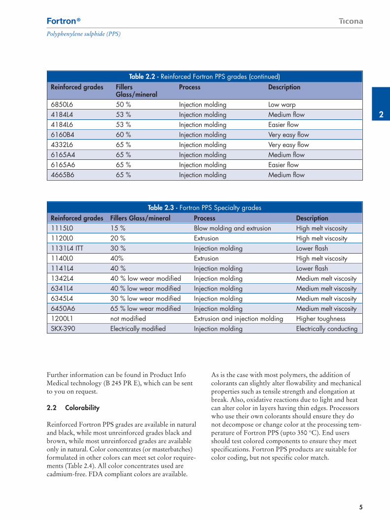
Further information can be found in Product InfoMedical technology (B 245 PR E), which can be sentto you on request.
2.2 Colorability
Reinforced Fortron PPS grades are available in naturaland black, while most unreinforced grades black andbrown, while most unreinforced grades are availableonly in natural. Color concentrates (or masterbatches)formulated in other colors can meet set color require-ments (Table 2.4). All color concentrates used arecadmium-free. FDA compliant colors are available.
As is the case with most polymers, the addition ofcolorants can slightly alter flowability and mechanicalproperties such as tensile strength and elongation atbreak. Also, oxidative reactions due to light and heatcan alter color in layers having thin edges. Processorswho use their own colorants should ensure they donot decompose or change color at the processing tem-perature of Fortron PPS (upto 350 °C). End usersshould test colored components to ensure they meetspecifications. Fortron PPS products are suitable forcolor coding, but not specific color match.
Table 2.2 · Reinforced Fortron PPS grades (continued)Reinforced grades Fillers Process Description
Glass/mineral6850L6 50 % Injection molding Low warp4184L4 53 % Injection molding Medium flow 4184L6 53 % Injection molding Easier flow6160B4 60 % Injection molding Very easy flow4332L6 65 % Injection molding Very easy flow6165A4 65 % Injection molding Medium flow 6165A6 65 % Injection molding Easier flow4665B6 65 % Injection molding Medium flow
Table 2.3 · Fortron PPS Specialty gradesReinforced grades Fillers Glass/mineral Process Description1115L0 15 % Blow molding and extrusion High melt viscosity1120L0 20 % Extrusion High melt viscosity1131L4 ITT 30 % Injection molding Lower flash1140L0 40% Extrusion High melt viscosity1141L4 40 % Injection molding Lower flash1342L4 40 % low wear modified Injection molding Medium melt viscosity6341L4 40 % low wear modified Injection molding Medium melt viscosity6345L4 30 % low wear modified Injection molding Medium melt viscosity6450A6 65 % low wear modified Injection molding Medium melt viscosity1200L1 not modified Extrusion and injection molding Higher toughnessSKX-390 Electrically modified Injection molding Electrically conducting

6
Fortron®
Polyphenylene sulphide (PPS)
2.3 Packaging
Fortron products are available in 15, 20 and 25 kgbags, 500 kg supersacks, 500 kg and 750kg gaylordboxes. Certain products are available only in specificpackaging sizes.
2.4 Quality assurance
Meeting the quality requirements of our customers isa critical activity for Ticona. We constantly pursueand update the certifications needed for this purpose.Our quality management system has been certified toISO 9000 standards since the early 1990s. In 2003, webuilt on this foundation by implementing the GlobalTicona Integrated Management System (TIMS) forquality, environmental and risk management.
Important certifications include the followingstandards:
� ISO 9001� ISO 14001� ISO/TS 16949� ISO/IEC 17025
Quality Management System Certifications underISO 9001:2000 and ISO/TS 16949:2002 have nowbeen achieved for all production sites and supportingremote locations of Ticona worldwide. The ISO/TS16949:2002 standard combines the automotive regula-
tions in Europe of VDA 6.1, EAQF and AVSQ withthe requirements of QS-9000 in North America andsupersedes all of these. Ticona received the certifica-tion for this standard in 2003.
The Ticona Oberhausen site in Germany gainedregistration under ISO 14001, the EnvironmentalManagement System Standard, in 1999. All Ticonafacilities in the Americas achieved certifi cation underISO 14001 in 2002. At Kelsterbach, Germany, regis-tration has been completed 2005.
The appropriate Ticona laboratories are accredited tomeet general requirements according to ISO/IEC17025:2000 for testing and calibration laboratories.
Our www.ticona.com website provides further infor-mation under “Company” > “Quality and Certifica-tions”. This information includes the details ofbusiness lines and facilities covered and PDF files ofall certificates of registration.
Table 2.4Available color concentrates for Fortron PPS
Color No. Standard Letdown. ColorSD3002 K40 40:1 BlackSD3039 K40 40:1 FDA BlackSJ3013 K20 20:1 GreenSY3004 K40 40:1 BrownSN3012 K20 20:1 OrangeSC3010 K20 20:1 Dark GreySC3011 K20 20:1 Pale GreySL3017 K20 20:1 YellowSS3006 K20 20:1 RedSG3005 K20 20:1 Blue

2
3
7
Fortron®
Polyphenylene sulphide (PPS)
3. Properties
Fortron PPS is an advanced polymer that performswell in challenging environments. It provides highhardness, rigidity and dimensional stability, excellentthermal resistance, inherent flame-retardance, and lowcreep and moisture absorption, among many otherbenefits. Furthermore Fortron PPS shows an excellentmedia resistance.
The data in Table 3.1, which derive from standard testmethods, form a basis for comparing differentFortron grades. While the data in the table is repre-sentative of typical values, components should betested in use to ensure they meet the specifications.
The data listed in Table 3.1 shows an extract of theproduct portfolio. Further data is listed in the ShortTerm Property Guide.
3.1. Physical properties
Grades in the Fortron PPS family have a density offrom 1.35 to over 2.0 gm/cm3. Fortron PPS has mini-mal water absorption: just 0.01 to 0.02% after 24hours of immersion at 23 °C. It also provides excellentdimensional stability in molding.
3.2 Mechanical properties
All plastic’s mechanical properties change with tem-perature. Figure 3.1 illustrates how the shear modulusand mechanical loss factor of Fortron PPS vary attemperatures from – 100 to 300 °C. The inflections on
the curves are indicative of the glass transition regionat about 90 °C and the melting region at about 280 °C.
3.2.1 Properties under short-term stress
The behavior of materials under dynamic short-termstress, as measured by ISO 527-1, 2, determinestensile strength and strain at break. Figs. 3.2 and 3.3show the stress-strain properties of Fortron 1140L4and 6165A4 at five temperatures from -30 to 200 °C.Both the 40% glass reinforced Fortron 1140L4 andthe 65% glass reinforced/mineral filled Fortron6165A4 grades have similar responses below andabove the glass transition region.
Other short-term stress properties include tensile mod-ulus and flexural modulus as determined by ISO 527-1,2 and ISO 178. These moduli indicate rigidity andso help in characterizing plastics and in calculatingstrength when designing molded parts. Tensile andflexural moduli in Fortron PPS decrease as temperaturerises to about 80 °C and drop sharply between about 80 to 120 °C. Reinforced Fortron PPS has high tensileand flexural moduli (Fig. 3.4 and 3.5). Both moduli arehigher for Fortron 6165A4, a 65% mineral filled blend,than for grades with 40% glass fibers.
3.2.2 Properties under long-term stress
Long-term testing provides design data for com-ponents that must withstand prolonged stress. Such testing involves two basic methods: the creeprupture test (ISO 899-1), which measures howdeformation increases in a specimen under constantstress, and the stress relaxation test (DIN 53 441),which measures how stress decays in a specimen atconstant strain.
The creep rupture test gives creep strength, or thetime it takes a test specimen to rupture at a set tensilestress under defined environmental conditions, eitherin air or in another medium. The strain values andcreep moduli it defines are good approximations forthe values expected under flexural and compressivestress in actual use. This test involves a uniaxial stressand has limited applicability when multiaxial stressesare present.
Fig. 3.1 · Shear modulus and mechanical loss factoras a function of temperature (ISO 6721-1,2)
–100 –60 –20 20 60 100 140 180 220 °C 300
104
MPa103
102
101
100
10–1
103
102
101
100
10–1
10–2
Temperature
a Fortron 6165A4b Fortron 1140L4c Fortron 0214C1
Shea
r m
odul
us G
Mec
hani
cal l
oss
fact
or d
a
c
a
c
d
Gb
b

8
Fortron®
Polyphenylene sulphide (PPS)
Table 3.1 · Short-term properties for selected Fortron PPS products*Physical Test Method 1140L4 6165A4 0320 0214Density, g/cm3 ISO 1183 1650 1950 1350 1350
Mold shrinkage – parallel, % ISO 294-4 0.2 – 0.6 0.2 – 0.6 1.2 to 1.5 1.2 to 1.5
Mold shrinkage – normal, % ISO 294-4 0.4 – 0.6 0.3 – 0.7 1.5 to 1.8 1.5 to 1.8
Water absorption (23 °C-sat), % ISO 62 <0.02 <0.02 <0.02 <0.02
Mechanical PropertiesTensile modulus (1mm/min), MPa ISO 527-2/1A 14700 19000 3800
Tensile stress at break (5mm/min), MPa ISO 527-2/1A 195 130 90 90
Tensile strain at break (5mm/min), % ISO 527-2/1A 1.9 1.2 8 3
Flexural modulus (23 °C), MPa ISO 178 14500 18800 4200 3750
Flexural stress @ break, MPa ISO 178 285 210 145 125
Charpy impact strength @ 23 °C, KJ/m2 ISO 179/1eU 53 20
Charpy impact strength @ 30 °C, KJ/m2 ISO 179/1eU 53 20
Charpy notched impact strength @ 23 °C,KJ/m2 ISO 179/1eA 10 7
Charpy notched impact strength @-30 °C, KJ/m2 ISO 179/1eA 10 7
Unnotched impact strength (Izod) @ 23 °C, KJ/m2 ISO 180/1U 34 20 82 45
Notched impact strength (Izod) @ 23 °C, KJ/m2 ISO 180/1A 10 6 2.6 3.5
Notched impact strength (Izod) @ 30 °C, KJ/m2 ISO 180/1A 10 6 2.5
Rockwell hardness, M-Scale ISO 2039-2 100 100 90 95
Thermal PropertiesMelting temperature (10 C/min), °C ISO 11357-1,-2,-3 280 280 280 280
Glass transition temperature (10 C/min), °C ISO11357-1,-2,-3 90 90 90 90
DTUL @ 1.8 MPa, °C ISO 75-1, -2 270 270 115 110
DTUL @ 8.0 MPa, °C ISO 75-1, -2 215 215 95 95
Coeff. of linear therm expansion (parallel), 10–4/°C ISO 11359-2 0.26 0.19 0.52 0.52
Coeff. of linear therm expansion (normal), 10–4/°C ISO 11359-2 0.62 0.24 0.53 0.53
Limiting oxygen index (LOI), % ISO 4589 47 53
Flammability / thickness tested (h), mm UL94 V-0 / 0.38 V-0 / 0.75 V-0 / 3
Electrical PropertiesRelative permittivity – 10KHz IEC 60250 4 5.4 2.7 3.2
Dissipation factor – 10KHz, 10–4 IEC 60250 2 10
Dissipation factor – 1MHz, 10–4 IEC 60250 62 20 11
Volume resistivity, Ω · m IEC 60093 >1013 >1015 109 109
Surface resistivity, Ω IEC 60093 >1015 >1015
Electric strength, KV/mm IEC 60243-1 28 25 18 18
Comparative tracking index CTI IEC 60112 125 175 125 125
* For more detailed information on the properties of Fortron PPS, see either the Ticona website, www.ticona.com, the Fortron PPS Short Term Properties brochure.

3
9
Fortron®
Polyphenylene sulphide (PPS)
The deformation of a plastic component depends ontime, temperature and type of stress. When defor-mation is relatively small, the variation between thecharacteristic values is negligible so a part’s time-dependent compression under compressive stress canbe calculated with sufficient accuracy using the flexuralcreep modulus (determined under flexural stress).
Creep rupture testing shows that reinforced FortronPPS has little tendency to creep, as can be seen inFigures 3.6 to 3.8 for Fortron 1140L4. The tests weredone under load for up to 1,000 hours and extra-polated to 10,000 hours. For a full set of creep-related
curves for Fortron 1140L4 and 6165A6 at other tem-peratures, see the Ticona web site.
In addition to creep under tensile stress, a polymer’sbehavior under flexural stress is important whendesigning many structural components. Figs. 3.9 and3.10 show the flexural creep modulus curves forFortron 1140L4 and 6165A4 at 80, 120 and 200 °C. At temperatures above and below the glass transitiontemperature (Tg) of 80 °C and 120 °C respectively, therates of decay of flexural creep modulus are similar,indicating that the material does not change in behaviorappreciably above and below the Tg. Figure 3.10
Fig. 3.4 · Tensile modulusfor selected Fortron PPS grades
–40 0 40 80 120 160 200 °C 240
20 000MPa
15 000
10 000
5 000
0
Temperature
Tens
ile m
odul
us
a Fortron 6165A4b Fortron 4184L4c Fortron 1140L4
ab
c
–40 0 40 80 120 160 200 °C 240
20 000MPa
15 000
10 000
5 000
0
Temperature
Flex
ural
mod
ulus
a Fortron 6165A4b Fortron 4184L4c Fortron 1140L4
a
b
c
Fig. 3.5 · Flexural modulus for selected Fortron PPS grades
Fig. 3.2 · Stress/strain curves for Fortron 1140L4 at five temperatures
Fig. 3.3 · Stress/strain curves for Fortron 6165A4 at five temperatures
a
b
c
de
0 0.5 1 1.5 2 2.5 3 % 4
a Temperature –30 °Cb Temperature 23 °Cc Temperature 70 °C
d Temperature 150 °Ce Temperature 200 °C
Stre
ss
250
200
150
100
50
0
a
b
c
de
0 0.5 1 1.5 2 2.5 3 3.5 % 4.5
a Temperature –30 °Cb Temperature 23 °Cc Temperature 70 °C
d Temperature 150 °Ce Temperature 200 °C
Stre
ss
160
MPa
120
100
80
60
40
20
0
Strain
Strain
MPa

10
Fortron®
Polyphenylene sulphide (PPS)
Fig. 3.7 · Fortron 1140L4 (temperature of 120 °C)
e = Time 10000 h
Strain
a b c d e
0 0.1 0.2 0.3 0.4 0.5 0.6 0.7 0.8 % 1
a = Time 1 hb = Time 10 h
c = Time 100 hd = Time 1000 h
Stre
ss
25
20
15
10
5
0
ab
c
d
e
1 10 100 1000 h 10000
a = 4.5 b = 9 c = 13.5 d = 18 e = 22.5
Mod
ulus
16000
MPa
12000
10000
8000
6000
4000
2000
0
Time
0 0.05 0.1 0.15 0.2 0.25 0.3 0.35 % 0.45
Stre
ss
70
MPa
50
40
30
20
10
0
abcd
e
1 10 100 1000 h 10000
a = 12 b = 24 c = 36 d = 48 e = 60M
odul
us
18000
MPa
17000
16500
16000
15500
15000
14500
14000
Strain Time
e = Time 10000 ha = Time 1 hb = Time 10 h
c = Time 100 hd = Time 1000 h
a b c d e
Fig. 3.6 · Fortron 1140L4 (standard climatic conditions 23/50)
Fig. 3.8 · Fortron 1140L4 (temperature of 200 °C)
e = Time 10000 h
Strain0 0.1 0.2 0.3 0.4 0.5 % 0.7
a = Time 1 hb = Time 10 h
c = Time 100 hd = Time 1000 h
Stre
ss
25
20
15
10
5
0
abc
1 10 100 1000 h 10000
a = 4.5 b = 9 c = 13.5 d = 18 e = 22.5
Mod
ulus
6500
MPa
5500
5000
4500
4000
3500
3000
Time
de
a b c d e
MPa
MPa

3
11
Fortron®
Polyphenylene sulphide (PPS)
shows a similar behavior even at a significantly highertemperature of 200 °C.
3.2.3 Fatigue
Fatigue strength is an essential parameter for partssubjected to periodic loading. It is defined as thestress amplitude, �a, that a specimen can withstandwithout failure for a set number of load cycles at aspecified average stress, �m. The various stress rangesfor such tests are shown in Fig. 3.11 as “Wöhlercurves”.
Fatigue strength for Fortron PPS at 107 load cycles isabout 15% to 30% of its tensile strength. Fig. 3.12and 3.13 show how Fortron 1140L4 and 6165A4 PPSbehave in the fluctuating tensile stress range at 23 °Cand 90 °C. Fatigue strength falls as temperature andload cycle frequency increase. Wöhler curves forfluctuating flexural stress for four Fortron grades areshown in Fig. 3.14.
Fig. 3.10 · Flexural creep modulus for Fortron 1140L4 and 6165A4 at 200 °C
(measured with an outer-fiber stress �b = 30 MPa)
10–2 10–1 100 101 102 103 h 104
Flex
ural
cre
ep m
odul
us
Time under stress
6 000
MPa
5 000
4 000
3 000
2 000
1000
0
1140L46165A4
Fig. 3.9 · Flexural creep modulus for Fortron 1140L4 and 6165A4 at 80 and 120 °C(measured with an outer-fiber stress �b = 50 MPa)
10–2 10–1 100 101 102 103 h 104
Flex
ural
cre
ep m
odul
us
Time under stress
20 000
MPa
15 000
10 000
5 000
0
1140L46165A4
80°C
120°C
Fig. 3.12 · Wöhler curve for Fortron 1140L4 and6165A4, determined in the fluctuating tensile
stress range at 23 °C
102 103 104 105 106 107 108
Stress cycles N
60MPa
50
40
30
20
10
0Fatig
ue s
treng
th u
nder
fluct
uatin
g te
nsile
stre
ss
6165A4
1140L4
Test temperature 23 °CStress cycle frequency 5 Hz
�m
=�
a
time0
Fig. 3.11 · Stress ranges in fatigue tests
range for fluctuatingstresses
(under compression)
range for alternatingstresses
range for fluctuatingstresses
(under tension)
+ �
– �
�m� �a �m� �a �m� �a
�m
��
a
�m
��
a
�u
�0
�u�
0
�m
�0
�m
��
a
�m
��
a
�m
��
a
�m
��
a
timeD
ruck
–
+
tens
ion

12
Fortron®
Polyphenylene sulphide (PPS)
3.3 Thermal
Fortron PPS is used in high-temperature environ-ments because of its exceptional thermal properties.The service temperature of Fortron PPS is up to240°C. These grades have pronounced thermaltransition ranges:
– Glass temperature, Tg : 85 – 95 °C– Precrystallization temperature, Tcc : 120 – 130 °C– Recrystallization temperature, Tch : 220 – 255 °C– Crystalline melting range, Tm : 275 – 285 °C– Heat of Fusion About 112 J/g1
Such transitions are important in processing. Forinstance, in injection molding it is important to setmold wall temperature above Tcc.
3.3.1 Deflection temperature under load
Deflection temperature under load (DTUL), deter-mined by ISO 75-1, 2 at test stresses A, B and C(A = 1.8 MPa, B = 0.45 MPa, C = 8.0 MPa), providesinitial guidance as to the continuous service tempera-ture a plastic can withstand. Figure 3.15 compares theDTUL for five Fortron PPS grades (at stress level Aand C) with that of liquid crystal polymer, polyesterand acetal copolymer.
Fig. 3.13 · Wöhler curve for Fortron 1140L4 and6165A4, determined in the fluctuating tensile
stress range at 90 °C
102 103 104 105 106 107 108
Stress cycles N
40MPa
30
20
10
0Fatig
ue s
treng
th u
nder
fluct
uatin
g te
nsile
stre
ss 6165A4
1140L4Test temperature 90 °CStress cycle frequency 5 Hz
�m
=�
a
time0
102 103 104 105 106 107 108
Stress cycles N
120MPa100
80
60
40
20
0
Stre
ss a
mpl
itude
� �
a
1140L44184L46165A44665B6
Test temperature 23 °CStress cycle frequency 10 Hz
+ �
– �
�m = 0
time
Fig. 3.14 · Wöhler curve for four Fortron grades in the fluctuation tensile stress
range at 23 °C.
0
50
100
150
200
250
300
HDT/C (8.0 MPa)
HDT/A (1.8 MPa)
Hos
tafo
rm C
902
1G
V1/4
0
Impe
t 270
0G
V1/4
5
Cel
anex
230
0G
V1/5
0
Vect
ra E
130i
(30%
GF)
Vect
ra A
130
(30%
GF)
Fortr
on 6
165A
4 65
% G
F/M
IN)
Fortr
on 4
184L
4(5
3% G
F/M
IN)
Fortr
on 1
140L
4(4
0% G
F)
Fortr
on 1
131L
4IT
T (3
0% G
F)
Fortr
on 0
205
(unf
illed
)
Figure 3.15 · Deflection temperature under load for Fortron PPS and other resins
°C
3
13
Fortron®
Polyphenylene sulphide (PPS)
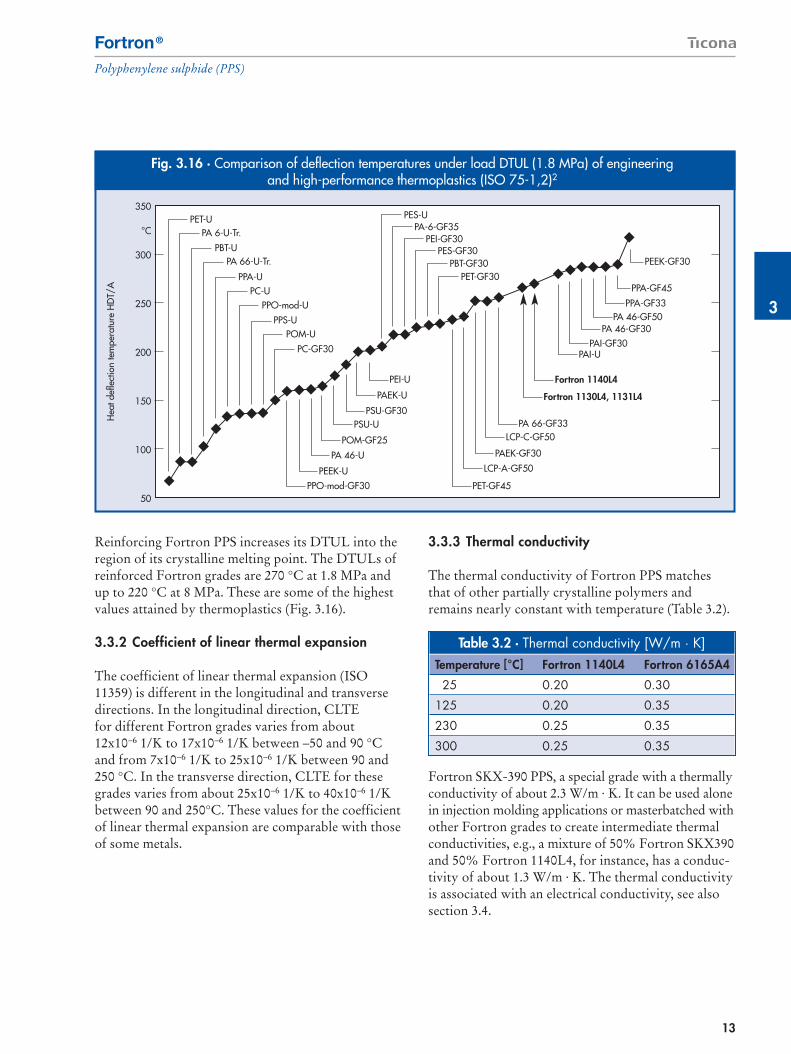
Reinforcing Fortron PPS increases its DTUL into theregion of its crystalline melting point. The DTULs ofreinforced Fortron grades are 270 °C at 1.8 MPa andup to 220 °C at 8 MPa. These are some of the highestvalues attained by thermoplastics (Fig. 3.16).
3.3.2 Coefficient of linear thermal expansion
The coefficient of linear thermal expansion (ISO11359) is different in the longitudinal and transversedirections. In the longitudinal direction, CLTEfor different Fortron grades varies from about12x10–6 1/K to 17x10–6 1/K between –50 and 90 °Cand from 7x10⁻⁶ 1/K to 25x10–6 1/K between 90 and250 °C. In the transverse direction, CLTE for thesegrades varies from about 25x10–6 1/K to 40x10–6 1/Kbetween 90 and 250°C. These values for the coefficientof linear thermal expansion are comparable with thoseof some metals.
3.3.3 Thermal conductivity
The thermal conductivity of Fortron PPS matchesthat of other partially crystalline polymers andremains nearly constant with temperature (Table 3.2).
Fortron SKX-390 PPS, a special grade with a thermallyconductivity of about 2.3 W/m · K. It can be used alonein injection molding applications or masterbatched withother Fortron grades to create intermediate thermalconductivities, e.g., a mixture of 50% Fortron SKX390and 50% Fortron 1140L4, for instance, has a conduc-tivity of about 1.3 W/m · K. The thermal conductivityis associated with an electrical conductivity, see alsosection 3.4.
Fig. 3.16 · Comparison of deflection temperatures under load DTUL (1.8 MPa) of engineering and high-performance thermoplastics (ISO 75-1,2)2
350
°C
300
250
200
150
100
50
Hea
t def
lect
ion
tem
pera
ture
HD
T/A
PET-U
PPO-mod-GF30PEEK-U
PA 46-U
POM-GF25
PSU-UPSU-GF30
PAEK-U
PEI-U
PET-GF45
LCP-A-GF50
PAEK-GF30
LCP-C-GF50PA 66-GF33
Fortron 1130L4, 1131L4
Fortron 1140L4
PAI-UPAI-GF30
PA 46-GF30PA 46-GF50
PPA-GF33
PPA-GF45
PEEK-GF30
PES-UPA-6-GF35
PEI-GF30PES-GF30
PBT-GF30PET-GF30
PA 6-U-Tr.
PBT-UPA 66-U-Tr.
PPA-UPC-U
PPO-mod-U
PPS-UPOM-U
PC-GF30
Table 3.2 · Thermal conductivity [W/m · K]Temperature [°C] Fortron 1140L4 Fortron 6165A4
25 0.20 0.30
125 0.20 0.35
230 0.25 0.35
300 0.25 0.35

14
Fortron®
Polyphenylene sulphide (PPS)
3.3.4 Soldering resistance
Reinforced Fortron PPS grades are often used in sur-face mounted devices (SMD) attached to circuitboards and other components by vapor phase, in-frared- or wave soldering. Fortron has excellent di-mensional stability and a very low and predictableshrinkage at high soldering temperatures. Bowing orwarping is minimized in an optimally molded part.Withstanding these higher temperatures can makelead-free soldering possible (RoHS and WEEE).
3.3.5 Flammability and combustion
Fortron PPS is inherently flame-retardant (it is ratedat UL 94: V-0, with some grades rated at 5 VA) andneeds no flame-retardant addition to pass UL-typeflammability tests.
The limiting oxygen index (LOI) is the minimumpercent of oxygen in air needed for a polymer tocontinue to burn after ignition without an additionalsource of energy. The LOI of Fortron ranges at about50 %. Since the atmosphere contains about 21% oxy-gen, PPS does not sustain burning under normal con-ditions.
The hot wire test in IEC 60695 part 2-1 (for 1, 2 and 4 mm thicknesses) yielded a value of 960 °C in eachcase for five Fortron grades (1140L4, 4184L4, 4665B6,6160B4 and 6165A4). In addition, Fortron 1140L4,6165A4 and 4665B6 PPS were evaluated under the
IEC 60335 glow wire test at 1, 2 and 3 mm thicknesses.In passing this test, flame duration lasted 24 seconds orless after heating ceased (at temperatures to 850 °C). In most cases, burning extended less than 3 mm intothe samples.
The five grades used in the hot wire test above werealso tested under the US Vehicle Safety StandardFMVSS 302. None of the grades flamed after a flamewas applied for 15 seconds, so burning rate could not be specified. This indicated excellent resistance. In addition, Fortron 1140L4 natural meets therequirements of the building class B2 under DIN 4102,part 1 at wall thicknesses of 3 and 6 mm (testingfollowed DIN 50 050 part 1 (1/88) at application offlame to the edge).
Flammability testing following procedures defined in National Bureau of Standards, NFPA 258, foundthat smoke from smoldering Fortron would notobscure a typical room (Table 3.3).
Different Fortron PPS grades were tested accordingto the standards of the aircraft and rail vehicle con-struction industries.
Fortron 0214C1 and 1140L4 meet all the require-ments of FAR 25.853 and ABD0031. FAR 25.853 isthe legal specification for the aircraft industry.ABD0031 (Airbus standard) includes FAR 25.853 but,in addition to flammability and smoke density tests,also contains toxicity tests.
Table 3.3 · Fortron PPS Smoke Density*Fortron 1140L4 Fortron 6165A4
Specimen – 1/8” (3.2 mm) Smoldering Flaming Smoldering FlamingMax. Value of Specific Optical Density** (DS) 12 95 10 44DS, corrected 11 91 9 42Spec. Opt. Density @ 1.5 minimum 0 1 0 0Spec. Opt. Density @ 4.0 minimum 0 18 1 4Obscuration Time*** (min) (Time to DS-16) — 4.1 — 7.1
* Following procedures proposed by the National Bureau of Standards, NFPA 258. Tests conducted in an Aminco-NBS Smoke Density Chamber.** Optical density measures the attenuation of a light beam by smoke that accumulates in a closed chamber as a material decomposes and/or combusts.*** Obscuration time is the time it takes a typical room to reach a critical smoke density. At this density, an occupant’s vision would be impaired
by smoke and hinder his or her escape. The critical level of smoke density or specific optical density is 16.

3
15
Fortron®
Polyphenylene sulphide (PPS)
Fire resistance for the rail vehicle constructionindustry was tested on Fortron 0214C1 according toDIN 5510. The test was passed. The smoke densityand toxicity requirements according to DIN 5659were also fulfilled.
3.4 Electrical
Fortron PPS is a high-purity material with very low levels of ionic impurities. It has good electricalinsulating properties and a low dissipation factor, so it is a valued insulating material, especially at hightemperatures.
3.4.1 Volume and surface resistivity
The volume resistivity of unfilled Fortron grades at 23 °C is > 109 � · m, and of reinforced Fortron gradesis >1013 � · m (IEC 60093). These values diminishwith increasing temperature. Surface resistivity, whichindicates insulation resistance across a surface, dependson humidity and surface contamination. The surfaceresistivity of Forton is normally > 1015 � (IEC 60093).
Fortron SKX-390 is a special electrically conductivegrade having a volume resistivity of 400 and a surface resistivity of 500 Ohm. This grade also hasimproved thermal conductivity. The volume- andsurface resistivity is measured in accordance to IEC60093. This grade can be blended with other Fortronresins to tailor volume resistivity to a specific range(Fig. 3.17).
3.4.2 Relative permittivity and dissipation factor
Fortron PPS has a relative permittivity of 4.0 to 5.4 at 10 kHz and 4.1 to 5.6 at 1 MHz (Fig. 3.18). Thisfactor increases slightly with increasing temperature.
1.00E+18
� · m
1.00E+12
1.00E+09
1.00E+06
1.00E+03
1.00E+00
Fig. 3.17 · Surface Resistivity of Fortron SKX-390 PPS Blends
1140L46165A4
0 20 40 60 80 % 100
Percentage of Fortron SKX-390
0
2
4
6
8
1.8 GHz1 GHz1 MHz
Fortron 4665B6Fortron 1131L4Fortron 1140L4Fortron 0203P6
εr
Fig. 3.18 · Relative Permittivity of Selected Fortron Grades
1.0E-03
3.0E-03
5.0E-03
7.0E-03
9.0E-03
1.1E-02
1.3E-02
1.5E-02
1.7E-02
1.8 GHz
1 GHz
1 MHz
Fortron 4665B6Fortron 1131L4Fortron 1140L4Fortron 0203P6
tan δ
Fig. 3.19 · Dissipation Factors for Selected Fortron Grades
Spec
ific
Surf
ace
Resi
stivi
ty
16
Fortron®
Polyphenylene sulphide (PPS)
Dissipation factor, tan , is a measure of the energyloss in a dielectric material by conversion into heat.The values for Fortron PPS range from 0.2 to 1.0 · 10–3
at 10 kHz and from 1.0 to 2.0 · 10–3 at 1 MHz (Fig. 3.19).This factor depends on frequency and temperature.
3.4.3 Electric strength
Electric strength describes behavior under short-term,high-voltage stress and should not be used for con-tinuous stress conditions. In electric strength tests, thevoltage (at a frequency of 50 Hz) is steadily increasedat a rate of 1 kV/s until insulation breakdown occurs(IEC 60243-1). Fortron PPS has electric strengthvalues of 25 to 28 kV/mm.
3.5 Surface properties
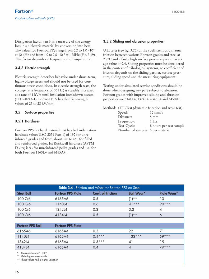
3.5.1 Hardness
Fortron PPS is a hard material that has ball indentationhardness values (ISO 2039 Part 1) of 190 for unre-inforced grades and from about 320 to 460 for filledand reinforced grades. Its Rockwell hardness (ASTMD 785) is 93 for unreinforced pellet grades and 100 forboth Fortron 1140L4 and 6165A4.
3.5.2 Sliding and abrasion properties
UTI tests (see fig. 3.20) of the coefficient of dynamicfriction between various Fortron grades and steel at23 °C and a fairly high surface pressure gave an aver-age value of 0.4. Sliding properties must be consideredin the context of tribological systems, so coefficient offriction depends on the sliding partner, surface pres-sure, sliding speed and the measuring equipment.
Testing under simulated service conditions should bedone when designing any part subject to abrasion.Fortron grades with improved sliding and abrasionproperties are 6341L4, 1324L4, 6345L4 and 6450A6.
Method: UTI-Test (dynamic frication and wear test)Speed: 10 mm/sDistance: 5 mmFrequency: 1 HzTest-Cycle: 8 hours per test sampleNumber of samples: 5 per material
Table 3.4 · Friction and Wear for Fortron PPS on SteelSteel Ball Fortron PPS Plate Coef. of Friction Ball Wear* Plate Wear*100 Cr6 6165A6 0.5 (1)** 10100 Cr6 1140L4 0.6 41*** 90***100 Cr6 1342L4 0.3 0.2 4100 Cr6 4184L4 0.5 (1)** 6
Fortron PPS Ball Fortron PPS Plate6165A6 6165A4 0.3 22 711140L4 6165A4 0.4*** 133*** 59***1342L4 6165A4 0.3*** 41 154184L4 6165A4 0.4 4 79**** Measured as mm2 · 10–3
** Grinding not measurable*** These values had a higher variation

3
4
17
Fortron®
Polyphenylene sulphide (PPS)
References
1. Cebe, P, Polymer and Polymeric Materials, 1995. 2. Modern Plastsics Encyclopedia ’95, Mid-
November 1994 Issue (71) 12, New York, p. B-150.
4. Environmental resistance
4.1 Thermal resistance
Fortron PPS has great resistance to thermal oxidation,so parts made from it withstand high thermal stress.The service environment affects the course of heataging, so terms such as heat resistance and continuoususe temperature should be considered in the contextof particular requirements. Experience shows thatFortron PPS generally withstands service tempera-tures as much as 240 °C for periods of years.
Figures 4.1 and 4.2 show the change in tensile strengthand elongation of Fortron 1140L4 in hot air as afunction of time1. The specimens were not subjectto mechanical load during the evaluation.
Fig. 3.20 · UTI Testing Method
Plate
FN = 6.3 N Ball (D=12.7mm)
020406080
100120140160180MPa220
42 days30 days20 days10 daysinitial value
Fortron 1140L4 200°CFortron 1140L4 240°C
Tens
ile s
treng
th
Fig. 4.1 · Heat Aging Test – tensile strength ofFortron 1140L4 black
42 days30 days20 days10 daysinitial value
Ten
sile
mod
ulus
0
2000
4000
6000
8000
10000
12000
14000
MPa
18000
Fortron 1140L4 200°CFortron 1140L4 240°C
Fig. 4.2 · Heat Aging Test – tensile modulus ofFortron 1140L4 black
18
Fortron®
Polyphenylene sulphide (PPS)
4.2 Moisture resistance
Fortron PPS is not hygroscopic. It absorbs just 0.02%water after immersion in water at 23 °C for 24 hours(ASTM Method D-570). This is far less than occursin many other polymers. Opposite to e.g. polyamidesit does not expand when exposed to water. It releasesthe absorbed moisture when stored in dry air.Absorbed atmospheric moisture causes no moleculardegradation.
Fortron PPS has excellent resistance to hydrolysis.It undergoes little or no change in tensile strength andelongation when exposed to 95ºC water for over1,000 hours at 15 psi. Glass-fiber-reinforced gradeslose some mechanical properties after immersion in 95 °C water after several months. As with many glass-fiber-reinforced plastics, this occurs through chemicalattack on the glass fibers and by capillary action at theglass fiber-polymer interfaces2.
4.3 Chemical resistance
Fortron PPS has superb chemical resistance. It doesnot dissolve in any known organic solvent below 200 °C and is virtually unaffected by acids, bases,alcohols, oxidizing bleaches and many other chemi-cals at elevated temperatures for extended times2. Its mechanical properties do decline, however, whenexposed to concentrated nitric and other oxidizingacids.
It has excellent resistance to all liquid and gaseousfuels, including methanol and ethanol, and withstandshot engine oils, greases, antifreeze and other automo-tive fluids. It is especially useful in fuel applicationsbecause of its stability during prolonged contact withgasoline formulations having various octane, sulfur,oxygenate and contaminant levels.
A 5000 hour/121 °C fuel immersion study comparinghow commonly used fuel system plastics age whenexposed to various gasoline blends (as defined in theSAE1681 protocol) confirmed that Fortron 1140L4had the least weight and dimensional change and thehighest tensile strength retention compared to nylon6/6, high temperature nylon (HTN) and polyphthala-mide (PPA). This was especially true with the moreaggressive fuels.
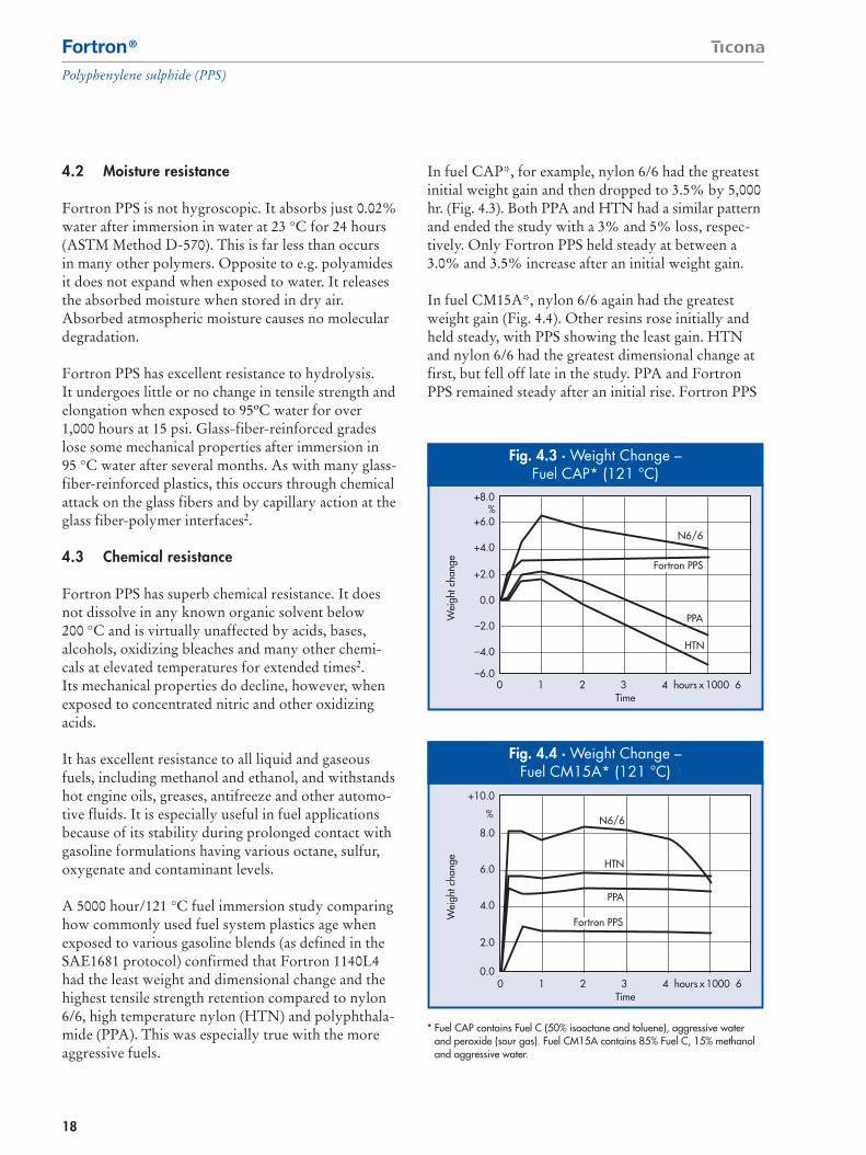
In fuel CAP*, for example, nylon 6/6 had the greatestinitial weight gain and then dropped to 3.5% by 5,000hr. (Fig. 4.3). Both PPA and HTN had a similar patternand ended the study with a 3% and 5% loss, respec-tively. Only Fortron PPS held steady at between a3.0% and 3.5% increase after an initial weight gain.
In fuel CM15A*, nylon 6/6 again had the greatestweight gain (Fig. 4.4). Other resins rose initially andheld steady, with PPS showing the least gain. HTNand nylon 6/6 had the greatest dimensional change atfirst, but fell off late in the study. PPA and FortronPPS remained steady after an initial rise. Fortron PPS
Fig. 4.4 · Weight Change –Fuel CM15A* (121 °C)
Fig. 4.3 · Weight Change –Fuel CAP* (121 °C)
N6/6
PPA
HTN
Fortron PPS
Time
Wei
ght c
hang
e
+8.0
+6.0
+4.0
+2.0
0.0
–2.0
–4.0
–6.00 1 2 3 4 hours x 1000 6
* Fuel CAP contains Fuel C (50% isooctane and toluene), aggressive waterand peroxide (sour gas). Fuel CM15A contains 85% Fuel C, 15% methanoland aggressive water.
N6/6
PPA
HTN
Fortron PPS
Time
Wei
ght c
hang
e
+10.0
8.0
6.0
4.0
2.0
0.00 1 2 3 4 hours x 1000 6
%
%

4
19
Fortron®
Polyphenylene sulphide (PPS)
retained 80% of its initial tensile strength by the endof the study, while the other materials had fallen tobetween 30% and 40% of their original values.
4.4 UV resistance
Fortron PPS has good resistance to ultraviolet radia-tion. Laboratory Weather-O-meter trials on unpig-mented and pigmented injection molded specimensshow little change in tensile strength, notched impactstrength and other mechanical properties after 2,000hours of exposure (Table 4.1).
4.5 Permeability
Fortron PPS is relatively impermeable to gases and tofuels and other liquids compared to other materials(Fig. 4.5 and 4.6). Permeation is lowest with unfilledFortron PPS grades. The combination of low perme-ability and high chemical resistance makes FortronPPS an excellent candidate for many automotive, in-dustrial, chemical, petroleum and aircraft applications,and where a high gas barrier is needed for medical andpackaging uses.
Table 4.1 · Change in the mechanical properties of Fortron PPS after UV exposure in anAtlas Weather-O-meter*
Tensile test according to ASTM D 638 ASTM D 256Fortron Grade Exposure time Tensile strength Strain at break Tensile modulus Notched impact
[hours] [MPa] [%] [MPa] strength (Izod) [J/m]1140L4 natural 0 181 1.7 15200 85
200 181 1.7 15200 85500 179 1.6 15200 851000 177 1.7 14500 852000 176 1.6 14500 85
1140L4 black 0 176 1.7 13800 80200 176 1.7 14500 75500 178 1.6 15200 801000 176 1.7 14500 802000 175 1.6 15200 80
* The tests used injection molded specimens according to ASTM G 23, Method 3, without water spray. It also involved a black standard temperature of 60 °C and a radiation intensity of 0.35 W/m2 · nm at a 30% relative humidity under a xenon arc lamp according to ASTM G 26. Mechanical properties were tested according to ASTM standards. None of the test specimen showed signs of erosion.

20
Fortron®
Polyphenylene sulphide (PPS)
References
1. Kohlhepp, K., “High-Performance Plastic forDifficult Components,“ Kunststoffe plast Europe,vol. 85, no 8 (German version: Kunststoffe 85(1995) 8, p. 1095 – 1100)
2. Fortron Chemical Resistance Guide Version 3.0,www.ticona.com
0
100
200
300
400
500
600
Nylon 12
EVOH
PPS
MethanolFAM A, 35% MethanolFAM A
Perm
eabi
lity
Coe
ffici
ent –
g m
m/m
2 /da
y
Fig. 4.5 · Comparative permeabilitycoefficients
Perm
eatio
n C
oeffi
cien
tin
100
μm
/m2
day
atm
0
500
1,000
1,500
2,000
2,500
3,000
3,500
69 °C60 °C
Polyketone
Nylon 11
Fortron
Temperature
Fig. 4.6CO2-Permeability

4
5
21
Fortron®
Polyphenylene sulphide (PPS)
Fortron PPS has become a proven material in manyindustries that have specialized requirements, frompotable water and automotive to healthcare and food.Over the years, it has been certified under a greatmany specifications and standards that apply to theseapplications.
5.1 Automotive specifications
Fortron PPS is marketed internationally and musttherefore comply with all the relevant automotiveindustry specifications applying to mechanical,electrical, thermal and other properties as well asflammability. Typical examples of automotive indus-try specifications that Fortron PPS meets include:
– The globally applicable Ford ISO specifications:– WSL-M4D 807-A for Fortron 1140L4 and
1140L6– WSF-M4D 803-A2 for Fortron 6165A4 and
6165A6
– Chrysler: MS-DB 570 CPN No. 3502 for Fortron1140L4, 4184L4 and 6165A4
– General Motors:– GMP.PPS.001 for Fortron 1140L4 and 1140L6– GMP.PPS.002 for Fortron 6165A4 and 6165A6– GMP.PPS.004 for Fortron 4184L4 and 4184L6
Fortron products are contained in the IMDS (Inter-national Material Data System), the materials databaseset up by the automotive industry. This internet-basedsystem (www.mdsystem.com) provides the auto-motive industry and its partners with informationon the constituents of the materials used in order tofacilitate recycling of end-of-life vehicles.
In addition, our products comply with the GADSL(Global Automotive Declarable Substance List),which replaces the individual standards of automotivemanufacturers. It can be accessed via the followinglink: http://www.gadsl.org.
5.2 Drinking water approvals
Fortron® PPS grades and color masterbatches basedon Fortron are generally suitable for use in the drink-ing water sector. Each country has its own approvalprocedure but they are all based on the same principle:the end customer sends his product to the testinginstitute, which then – on request – obtains the rele-vant formulation from the material manufacturer(e.g. Ticona) and conducts the test. Finally, the endcustomer is informed about the successful result ofthe test and receives a corresponding test certificatefrom the testing institute.
In some countries, Ticona has successfully conductedthe relevant tests for standard grades on test specimensto give end customers the best possible assurance thattheir products will also pass the official approval test.However, the possession of such a “material test cer-tificate” does not exempt end customers from havingtheir end products tested by a testing institute.
The most important approval application proceduresin EU countries (UK, F, D, NL) and the USA differin some details, which need to be taken into accountin the material approval tests.
UK – WRAS (Water Regulations Advisory Scheme)
Under the UK WRAS regulations, all materials mustbe listed before an end product approval test can becarried out: various Fortron® PPS grades are listedand “pretested” for contact with drinking water up toa temperature of 85°C – these can be viewed on theWRAS website: http://www.wras.co.uk/.
D – KTW (Kunststoffe im Trinkwasserbereich)Regulations on Plastics in the Drinking WaterSector
In Germany, the Fortron grade 1140L4 black success-fully passed the KTW tests, which were carried outon test plaques. The plaques were tested in cold waterand in hot water at 90°C. The KTW certificate wereceived for these tests is available on request.
5. Specifications and standards

22
Fortron®
Polyphenylene sulphide (PPS)
F – ACS (Attestation Conformité Sanitaire)Sanitary Conformity Certificate
The Fortron® PPS grades 1140L4 and 1140L6 PPS arecurrently being tested in the form of plaques for com-pliance with the French ACS requirements.
In the case of glass-fiber-reinforced plastics, the rele-vant glass fibers must be on the French positive listfor glass fibers before the end product can be tested;the fiber used in glass-fiber-reinforced Fortron® PPSgrades is listed.
USA – NSF (National Sanitary Foundation)
In the USA, the Fortron® PPS grades 1140L4 and1140L6 PPS have been successfully tested in accord-ance with the requirements of NSF Standard 61 andare therefore suitable for applications involving con-tact with drinking water.
Important: the drinking water regulations cover pro-ducts used in the drinking water supply system,which extends from the public reservoir, throughthe pipeline system and domestic installations to theend of the faucet. Once the water has left this system,products that come into contact with it as consumerarticles are exclusively subject to the FDA food-con-tact regulations (see section 5.3).
5.3 Products for food-contact applications/consumer articles
In the EU, the requirement for using plastics in con-tact with food is that the material components mustbe registered on a positive list in the German Regula-tions on Food-contact Articles (Bedarfsgegenstände-verordnung) or corresponding national regulations,such as the recommendations by the BfR (Bundes-institut für Risikobewertung = Federal Institute forRisk Assessment, previously known as the BgVV andBGA).
The monomers and other starting components usedin the manufacture of the Fortron grade 1140L4 arelisted in EU Directive 2002/72/EC and its 3 amend-ments 2004/1/EC, 2004/19/EC, 2005/79/EC. TheseEU lists are transposed into German national law inthe German Regulations on Food-contact Articles(Bedarfsgegenständeverordnung) of December 23,1997 (most recently amended on July 13, 2005).
If individual substances registered on the positive listare subject to specific restrictions, then the finishedpart must be tested for compliance with such specificrestrictions by the manufacturer or vendor. If the plas-tic consists of listed substances that are not subject toany specific restrictions, then the finished part mustbe test for compliance with global migration limits inaccordance with the EU Migration Directive(82/711/EEC).
In the case of Fortron® PPS polymers, a restrictionapplies to 1,4-dichlorobenzene: SML = 12 mg/kg foodproduct.
In the USA, the requirement for “repeated use”in contact with food is met through Food ContactSubstance Notification (FCN) No. 40 “Polyphenylenesulfide polymers (CAS Reg. No. 25212-74-2 or26125-40-6)” submitted to the US Food and DrugAdministration (FDA) (see also: http://www.cfsan.fda.gov).
5.4 Products for medical and pharmaceuticalapplications
The Fortron PPS MT 9000 series is the first PPS linecertified for medical, pharmaceutical and repeated-usefood contact applications. The grades in this linecomply with US Pharmacoepia Class VI, InternationalStandards Organization 10993, and U.S. Food andDrug Administration (FDA) Food Contact SubstanceNotification No. 40. FDA Drug and Device MasterFiles are also available for specific requirements. The series contains unreinforced grades for extrudingtubing, profiles and filaments, as well as reinforcedgrades for injection molding.

6
23
Fortron®
Polyphenylene sulphide (PPS)
Although Fortron PPS is traditionally seen as aninjection molding material, many other processes arecommonly used to convert it into useful products.These processes include extrusion for film, profile,pipe, filaments and fibers, as well as blow molding,thermoforming and composites. Sections 7, 8, 9 and10 look in some detail at specific processing areas.This section considers general topics that apply to allprocessing methods.
6.1 Safety
Fortron PPS is a relatively inert material that posesrelatively few safety issues in the processing environ-ment so long as a few simple steps are taken regardingthe maximum melt temperature and ventilation.
6.1.1 Thermal stress
Fortron PPS melts should not exceed 370 °C (takinginto account permissible extruder barrel residencetimes). Excessive thermal stress will degrade it andgenerate gases, including various sulfide compounds.If thermal degradation in the barrel is suspected orestablished, pump the charge out and quench in waterto minimize unpleasant odors. Refer to the MaterialSafety Data Sheet for additional detail regarding safehandling and processing.
6.1.2 Odors in processing
Although odors may occur when processing PPS,these odor species do not pose a health hazard. Odorscan occur in processing PPS under certain conditionsdue to the presence of residual, low-molecular-weightorganic species, including various sulfide compounds. When off-gassing by Fortron PPS during processingwas measured by personal industrial hygiene monitors,the levels of the organic gases found were consistentlybelow the detectable limits of the analytical methodsused and significantly below the regulatory and/orrecommended exposure limit.
Even so, when using PPS in injection molding, extru-sion and other processes, adequate local ventilation isrecommended. See the Material Safety Data Sheet foradditional safety and health information.
6.1.3 Fire precautions
Even though Fortron PPS is inherently flame-retardant,processors should take necessary fire preventionmeasures when storing, processing or fabricating thematerial, especially those defined by regulations inspecific countries. Some end products and fields ofapplication may be subject to special fire preventionrequirements. It is the responsibility of the raw mate-rial processor to ascertain and observe such require-ments. Again, Material Safety Data Sheets for theindividual Fortron grades are available.
6.2 Start up and shut down
During start-up, processing equipment should stabilizefor 30 minutes at the temperatures recommended.In injection molding, for instance, a machine shouldbe purged with an appropriate material (see section6.4) and then PPS should be fed until it is the onlymaterial exiting the die or nozzle. Check the melttemperature with a pyrometer to ensure that the meltis within the recommended temperature range. Whena machine that had used Fortron PPS is shut down,hold it at operating temperature until it is purged withan appropriate material.
6.3 Drying considerations
Although Fortron PPS is not hygroscopic and degra-dation due to moisture is unlikely, dry resin should be used in molding because high moisture levels cancreate voids and intrusive streaks near the gate thatcan affect part performance and aesthetics. Unfilledgrades (see Table 2.1) should be dried at 120 °Cfor 1-2 hours, reinforced grades (Table 2.2) at 140 °C> 4 hours. Some specialty grades may need milderconditions. Fortron PPS should be dried in dehumidi-fying hopper dryers.
6. General processing considerations
5

24
Fortron®
Polyphenylene sulphide (PPS)
6.4 Purging
6.4.1 Changing from another thermoplastic toFortron PPS
Many plastics are unstable at PPS processing tempe-ratures and should be removed from the machinebefore molding with Fortron PPS. Suitable purgingmaterials include high density polyethylene (HDPE),polyamide (PA) and cross-linked polymethylmethacrylate (PMMA). Such materials are ejected at the appropriate melt temperatures in rapid shotsequence with the cylinder disconnected from themold.
As soon as the previous material is expelled completely,cylinder temperatures are brought to the settingsrecommended for Fortron PPS. Fortron is then fedinto the molding machine until the purging material is expelled. Molding can begin when the purgingmaterial is fully removed.
6.4.2 Changing from Fortron to anotherthermoplastic
As soon as the melt is free of all traces of the PPS,cylinder temperatures should be reduced to a levelsuitable for the purging material as the melt continuesto flow out of the nozzle into the open (‘air-shot’).Purging is complete when the required temperaturesare reached.
Fortron PPS is injection molded in conventional screwinjection molding machines. Although it absorbs littlemoisture, it should be predried before being fed to themachine (see Section 6.3).
Mold temperature should be controlled precisely tocreate parts that remain dimensionally stable at highheat. A measured mold temperature of min. 140 °C isneeded so the PPS crystallizes. When a part that wasnot fully crystallized during processing is placed inservice above the original mold temperature, it willcrystallize and shrunk (see section 11.1). Molds pro-cessed with mold temperatures < 140°C may createrough surfaces. In cold-molded parts, filler can appearon the surface and be attacked by chemicals.
7.1 Equipment considerations
The process is crucial in producing high-quality parts,so it is essential to understand the molding processand equipment used. Figure 7.1 shows the basic partsof a single-stage, reciprocating screw injection mold-ing machine.
Clamping force keeps the mold closed and is devel-oped by either a toggle mechanism or a hydrauliccylinder. With Fortron PPS, this force in a typicalmolding machine should be between 5 and 6 kN/cm2
of projected area (including the runner).
Figure 7.1 · Molding machine schematic
Nozzle
Injection CylinderHeater Bands
Feed Hopper
Nonreturn FlowValve Assembly
Rotating andReciprocating Screw
7. Injection molding

25
Fortron®
Polyphenylene sulphide (PPS)
7.2 Mold design
7.2.1 Tool, screw, and barrel materials
Given the abrasive nature of glass and mineral fillers,molds, screws and barrel liners used with filled Fortrongrades must be made of the appropriate steels. For ex-perimental molds or those for production short-runs
(less than 50,000 molding cycles), the steels listed inTable 7.1 are sufficient. Molds for higher productionvolumes need steels having a having a hardness > 56HRc (Table 7.2) to ensure long cavity life and tighttolerances. Screws made of PM steels or hard metalsteels and cylinders made of Bimetals are common.Improper combinations of screw and barrel materialscan lead to premature wear, so molding machine
6
7
Table 7.1 · Tool Steels for Use with Fortron PPS (less than 50,000 injection molding cycles)Type of Steel Designation Material Surface Comments
in accord with Nr. hardness DIN 17 006 (HRc)
Case-Hardening Steels X 6CrMo4 1.2341 55 Not corrosion resistant 21 MnCr5 1.2162 55 low dimensional stability
Through-Hardening Steels X 210Cr 12 1.2080* 54 Not corrosion resistantX 38CrMoV 51 1.2343* 53 very good dimensional stabilityX 40CrMoV 51 1.2344* 55 high compressive strengthX 45NiCrMo4 1.2767* 4290 MnCrV 8 1.2842 43
Corrosion-Resistance Steels X 42CrMO 13 1.2083 51 Still inadequate corrosionX 36CrMo 17 1.2316 46 resistance and hardness
* Steel also available as electroslag remelting process grades with a more homogeneous structure and higher corrosion and wear resistance.
Table 7.2 · Tool Steels for Use with Fortron PPS (greater than 50,000 injection molding cycles)Type of Steel Designation Material Surface Comments
in accord with Nr. hardness DIN 17 006 (HRc)or trade name
Through-Hardening Steels X 155CrVMo 121 1.2379 58 Polishable, not corrosion resistantBöhler “M 340” — >56 Additional corrosion resistance
Maraging Steels Uddeholm “Elmax” — 57 Highly wear and corrosion (PM steels group) resistant
Böhler “K 190” — 60-63 Highly wear and corrosion resistantBöhler “M 390” — 56-62 Highly wear and corrosion resistantZapp CPM T420V — 57 Very easily polishableZapp CPM 3 V — 57-63 Additional toughness, not corrosion
resistantZapp CPM 9 V — 57-67 Additional toughness, not corrosion
resistantHard Metal Alloys Ferro-Titanit S — 66-70 Extremely high wear and corrosion
resistanceWST “G25” — 64-66 Extremely high wear and corrosion
resistance

26
Fortron®
Polyphenylene sulphide (PPS)
suppliers should be consulted on which materials touse together. Molds containing surface steels at orbelow 56 HRc-hardness can be further protectedagainst wear through hard-facing methods. In suchmethods, treatment temperature should never reachthe annealing temperature of the steel. Facing materialscan also be used. Chromium-containing facing mate-rials (e.g., chromium nitride) offer better wear protec-tion than titanium nitride. Highly wear-resistant,corrosion-resistant refractory hard metal alloys suchas “Ferro-Titanit S” can be used for inserts in the gateregion where shear is high and greater wear occurs.
7.2.2 Draft
Fortron PPS has relatively high rigidity and lowelongation, so draft is needed to aid part removal.Guidelines for proper draft include:
– Consider drafts of ≥ 1° in part areas perpen-dicular to the parting line.
– Drafts of less than 1° are possible for narrow partshaving short ejection paths and mold surfaces have
a high-gloss brushed finish in the ejection direction.Use of small draft angles in other situations mayrequire ejection pins to aid ejection.
– On grained mold surfaces, add a draft of 1° ormore for each 0.01 mm of grain depth.
7.2.3 Undercuts
Undercuts are indentations or protuberances in themolded part perpendicular to the ejection direction.They are either essential from the design viewpoint ormay be required for a component function.
Because of the high rigidity and low elongation ofFortron, undercuts that could prevent removal of themolding should be avoided. Such undercuts areonly possible if suitable mold parts such as splits orcollapsible cores are used.
Provided certain mold design and part ejectionrequirements are met, undercuts with low undercutdepths are possible without using special mold parts.The following recommendations should be observed:
Fig. 7.3 · Examples of a submarine gate
= 10 … 20° = 10 … 20°
d 1
d 2
d 2
d 2
d 1
� d 1
I 2
I 1
d 3S
SR
�
�
Usual only for wall thickness s � 4 mmd 1 = s + 4… 1 mm � = 30°d 2 = 0.8 … 0.5 · s = 30 … 35°d 3 = 1 … 0.8 · d 1 R = 2 mml 1 = 1 mml 2 = 10 … 20 mm no sharp edgesValue relationship = (small s value) … (large s value)
gate
gate
7
27
Fortron®
Polyphenylene sulphide (PPS)
– Maximum undercut depth, depending on moldingdesign and content of reinforcing material in thePPS:– h = 0.05 – 0.1 mm for 65% glass-fiber/mineral-
reinforced Fortron and– h = 0.1 – 0.2 mm for 40% glass-fiber-reinforced
Fortron– Provide the ejection surface in the mold with a
brushed finish in the ejection direction– Ensure an ejection angle of < 30° at wall thickness
transitions, radius corners and edges.
7.2.4 Sprues and runners
Sprues and runners should be designed to ensure abalanced filling behaviour. Sprues and runners shouldhave a 2 to 3° taper. A sprue diameter of 4 mm is oftenadequate. Sprue bushings, runners and gate channelsshould be polished.
Use full-round runners having diameters as small as3.2 mm (dependent on wall thickness), or equivalenttrapezoidal runners. Balance the runner system inmulticavity molds so all cavities finish filling at thesame time and no cavity is overpacked.
7.2.5 Gates
Multiple gates are often used for parts having longflow lengths and/or thin-walls to minimize pressureand flash. Locate gates so resin flow into the moldcavity is uniform and uninterrupted, while holdingthe number of gates present to a minimum. Place gatesso weld lines occur in areas having minimal load-bearing requirements. The addition of venting at weldlines promotes stronger welds.
Gates should be rectangular and sized as large aspossible to minimize wear.
All types of gates can be used with Fortron PPS1.Submarine or pinpoint gates typically measure > 1 mm(Fig 7.3). Tunnel gates should have an ejector pin at thegate to assist ejection. Generally the gate diameterdepends on the wall thickness in the gate area. Datasuggests gate diameters should be 0.5 to 0.8 times thewall thickness.
The usage of rectangular sprue is very common,as is the diaphragm sprue for single cavity concentricmoldings of ring shape with medium or small internaldiameter.
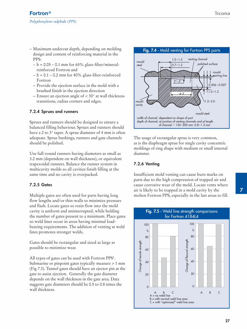
7.2.6 Venting
Insufficient mold venting can cause burn marks onparts due to the high compression of trapped air andcause corrosive wear of the mold. Locate vents whereair is likely to be trapped in a mold cavity by themolten Fortron PPS, especially in the last areas to fill.
Fig. 7.4 · Mold venting for Fortron PPS parts
width of channel: dependent on shape of partdepth of channel: at junction of venting channels and at length
of channel � 150–200 mm: 0.8–1.2 mm
mouldsteel
4–5
mouldparting line
mould steel
polished surface
venting channel1.0 –1.5
0.7–1.2
2°–5°
1.0 –1.2
0.006 – 0.007
mouldcavity
1.2– 2.0
Fig. 7.5 · Weld line strength comparisons for Fortron 4184L4
100
%
80
60
40
20
0
Cha
nge
of te
nsile
stre
ngth
100
%
80
60
40
20
0
A = no weld lineB = with normal weld line areaC = with “optimized” weld line area
Cha
nge
of fl
exur
al s
treng
th
A B C A B C

28
Fortron®
Polyphenylene sulphide (PPS)
Effective venting often involves channels in the part-ing line. Vent channel depth of the land zone shouldnot exceed 0.006 to 0.007 mm to prevent flashing.Channel width depends on molding size. It is best topolish the surface of the land zone and the surfaceopposite (Fig. 7.4). Venting may be achieved or im-proved with suitably machined ejector pins. Ventingof runners has also proven successful.
7.2.7 Weld lines
Reinforcing fibers near a weld line tends to orientparallel to the weld line, weakening the part. Placeweld lines in low-stress areas by positioning the gateproperly. Weld strength can be increased throughproper design, e.g., increasing wall thickness near weldlines or by using effective venting and others steps.Figure 7.5 compares tensile and flexural strength ofFortron 4184L4 (50% glass fiber reinforced) fordifferent weld line strengths.
7.2.8 Ribs and radii
Ribs should have the same thickness as the adjacentwall section, if possible. If sink marks occur in a wallopposite a rib, then restrict rib thickness to 0.5 to 0.7times the adjacent wall thickness. Use radii at thejunctions between ribs and adjacent walls. The radiusis usually 0.1 to 0.2 times the thickness of the adjacentwall. To avoid notch stresses in parts subject to highmechanical stress, use radii of at least 0.5 mm. Also,provide generous radii for changes in section, cornersand edges.
7.2.9 Tolerances
Fortron PPS can hold fine tolerances. Glass- andmineral-reinforced grades allow for tolerances below0.3%, although such extremely tight tolerances callfor proper design and careful attention to moldconstruction and the molding process.
Fig. 7.6 · Schematic of a hot runner system
Manifold
Cylinder Assembly Extension Nozzle
Band Heater
Pin GuideValve Pin
Bushing
Spiral Heater
Gate
Melt FlowChannel
(A)
(B)

7
29
Fortron®
Polyphenylene sulphide (PPS)
7.3 Hot runners
Fortron PPS uses hot-runner molds (Fig. 7.6) havingcomparable specifications, construction and operationas those for other engineering plastics. The design ofhot-runner systems (geometry, steel selection andcomponent selection) is usually done by the runnermanufacturer. The information below on the use ofhot runners with Fortron PPS should be applied incollaboration with runner manufacturers.
Use wear-resistant steels having a surface and workinghardness >56 HRc for long-life hot runner systems.The steel used in hot runner components (manifoldblocks, runners, nozzle tips, needles and needle guideparts and associated parts) can be coated or surfacetreated. (See 7.3.1 for further information on wearprotection.)
7.3.1 Hot runner nozzles
Fortron PPS can be processed by various nozzlesystems (Fig. 7.7). Use externally heated nozzles withFortron PPS. Internally heated systems and indirectlyheated nozzles do not heat the melt uniformly enough.They also can allow degraded material in the insulat-ing layer to cause molding defects and the insulatinglayer to cause high pressure drops with highly filledFortron PPS grades. Hot runner systems can be usedwhen set up involves direct gating or a connecting coldsub-runner. Standard interchangeable or screw-in gatebushings, nozzle tips, shut-off needles and needleguide parts are generally recommended for reinforcedFortron PPS grades.
– Free-flow nozzles– Not recommended for direct gating because of
material drooling and cold slugs– Nozzle drooling and cold slugs can be influenced
by changing the temperature in the hot runnerregion and land zone L (contact length with themold plate)
– Limited suitability for use with a cold sub-runner (indirect gating); cold slugs shouldbe retained in a slug well in the cold runner
– Nozzles with tips– Suitable for direct gating– Good temperature control of the nozzle can
avoid or keep cold slugs small– Needle shut-off nozzles
– Can be used with direct gating for standardreinforced Fortron PPS
– Melt isolation by the needle eliminates coldslugs, assuming ideal thermal design of the gateregion
– Side-gating nozzles– Suitable for direct gating perpendicular to the
parting line– Cold slugs can be kept small or avoided by good
temperature control of the nozzle and theproviding a tip that extends to the gating surface.
Fig. 7.7 · Processing conditions for reinforcedand unreinforced Fortron PPS
Cylinder temperatures: �1: 300– 320 °C�2: 310– 330 °C�3: 320– 340 °C�4: 320– 340 °C�M: 320– 340 °C�m: 310– 340 °C
Max. res. time in cylinder � 60 min(at 320 – 340 °C)
Injection pressure pf: 500–1000 bar (spec.)Holding pressure ph: 300 – 700 bar (spec.)Back pressure pA: lowScrew speed nS: low, e. g. 40–100 min-1
Injection rate: medium to highMould wall temperatures �C1, �C2: 140 –145 °CNozzle: free-flow nozzle, preferably
shut -off nozzle
Note:Tool steel, hardened and corrosion-resistant.Bimetallic cylinder and screw corrosion-resistant.
�D �4 �3 �2 �1 nS pSt, pSp, pN
�W1 �W2 �M

30
Fortron®
Polyphenylene sulphide (PPS)
7.4 Processing conditions
Fortron PPS can be processed on standard moldingmachines. Standard Fortron PPS grades at 135 °C for3 to 4 hours before using them (see section 6.3). Somespecialty grades may need milder conditions.
When starting processing, ensure that mold and injec-tion molding machine are thermally balanced.During start-up, stabilize the machine for 30 minutesat the recommended zone temperatures (Fig. 7.7)before rotating the screw. If purging is needed, usehigh-density polyethylene (HDPE), polypropylene(PP) or a special purging compound.
Check the melt temperature with a pyrometer toensure the melt is in the recommended temperaturerange. Be sure that the melt temperature does notexceed 370 °C. The minimum mold temperatureshould be 140 °C so the resin can crystallize.
When shutting down a machine that had used FortronPPS, hold the nozzle and barrel heaters at the moldingtemperature as they are purged with HDPE or PP.In case special purging material is used, it is stronglyrecommended to refer and adhere to the manufac-turer's MSDS.The machine can be turned off whenthe purging resin fills the barrel. Place the ram in theforward position for shut down.
Fortron PPS is an easy-to-mold material. Considera-tions to keep in mind when processing Fortron PPSinclude:
– Melt temperatures of 320 to 340 °C are recom-mended. If molding geometry requires it, e.g., a small wall thickness, melt temperatures to about340 °C are possible.
– Mold wall temperatures should be at least 140 °Cto allow a sufficient crystallization rate and degreeof crystallinity to create high-quality parts. It isbest to use circulating-oil heating systems. Electricheating can be used in experimental molds andshould have a power density of 40 to 50 W/kg.
– In practice, medium to fast injection speeds haveproven to work best, depending on part and molddesign. Mold venting is key to success.
– Screw speed should fall between 40 and 100 min–1,depending on screw diameter.
– For plasticization a back pressure less than 30 bar issufficient. A higher back pressure accelerates screwwear.
– Specific injection pressure should be between 500and 1000 bar.
– Specific holding pressure is normally between300 and 700 bar (as specific pressure, to be con-verted to hydraulic pressure).
– Holding pressure time depends mainly on the de-sign of the runner and the gate and the wall thick-ness of the molded part. The required hold timecan be optimized at the point of gate freeze. Lowerholdong times may lead to warpage (fig. 7.8).
– Barrel residence times longer than 20 minutes may cause a modest decrease in viscosity and colordarkening, although mechanical properties arevirtually unchanged.
– Cycle time depends on the part molded.Theoretical cooling times are 20 to 30 seconds for4 mm-thick parts, 10 to 15 seconds for 2.5 mm-thickparts, and 5 to 10 seconds for 1.5 mm-thick parts.
– Recommended is a shot weight of 50 to 70% of amachine’s capacity.
Fig. 7.8 · Optimum holdingpressure time
Holding pressure time th
Mouldingweight warpage tendency
increases when tN � tNo
tNo

7
31
Fortron®
Polyphenylene sulphide (PPS)
Fig. 7.10 · Mechanical properties for regrindaddition for Fortron 6165A4 regrind addition for
Fortron 1140L6
1140L6 25% 50% 75% 100%
%
100
90
80
70
60
50
Starting material Regrind
Dec
line
in m
easu
red
valu
es
a tensile modulusb strain at break
c notched impact strength (Charpy)d impact strength (Charpy)e tensile strength
a b
c
e d
Fig. 7.9 · Mechanical properties forregrind addition for Fortron 6165A4
6165A4 25% 50% 75% 100%
%
100
90
80
70
60
50
Starting material Regrind
Dec
line
in m
easu
red
valu
es
a tensile modulusb strain at break
c notched impact strength (Charpy)d impact strength (Charpy)e tensile strength
ab
c
e
d
Original 1x 2x 3x 4x 5xmaterial Number of recycling loops
%100
90
80
70
60
50
40
Dec
line
in m
easu
red
valu
es
a tensile modulusb strain at break
c tensile strengthd damage forcee damage energy
b
ac
e
d
Fig. 7.11 · Mechanical properties as a function multiple processing
7.5 Use of regrind
Fortron PPS can be recycled by remelting and repel-letizing. Sprues, rejects and post-consumer parts thatare clean and not thermally degraded can be reprocessedas regrind in blends with virgin material. Parts to berecycled must be clean, dry and properly sorted. Tominimize damage to fillers and fibers in Fortron PPScompounds during granulation, grind parts under thegentlest possible conditions.
Regrind can impair feed behavior, so it is best to matchregrind particle size to the pellet size of the virginmaterial. Regrind content of 25 to 30% should not beexceeded (Fig.7.9 and 7.10). If too much regrind isused, molded parts properties are likely to deteriorate.If a resin has been recycled several times, some declinein physical properties will occur (Fig. 7.11).
32
Fortron®
Polyphenylene sulphide (PPS)
7.6 Troubleshooting guidelines
Many processing problems are caused by easily cor-rected conditions, such as inadequate drying, incorrecttemperatures and/or pressures, etc. Solutions can oftenbe found by following the recommendations givenbelow. Try them in the order in which they are listedin each problem category.
Burn Marks– Check for adequate ventilation– Decrease the injection speed– Decrease the booster time– Alter the position of the gate– Increase the gate size.
Discoloration in Fortron PPS may be caused by ex-cessive temperatures. It is more of a surface phenome-non and is not necessarily indicative of degradation.
– Purge the heating cylinder– Reduce the material temperature by:
– Lowering the cylinder temperature settings– Decreasing the screw rotational speed– Lowering the back pressure
– Lower the nozzle temperature– Shorten the overall cycle time– Check the hopper and feed zone for contamination– Check the ram and feed zone for proper cooling– Move the mold to a press with a smaller shot size– Provide additional vents in the mold.
Dull Surface Appearance is generally caused by toocold a mold (less than 135 °C).
– Increase the mold temperature– Increase the injection speed– Increase the packing/hold pressure.
Flash Reduction– Check to see that the mold is closing properly– Check for material caught on the parting surface– Reduce the material temperature by:
– Lowering cylinder temperature settings– Decreasing screw rotational speed– Lowering back pressure
– Decrease injection pressure/speed– Decrease injection hold time/booster time– Check parting line of mold for wear– Move the mold to a larger (clamp) press if injection
pressure is too high– Reduce pressure by using lower viscosity grade of
resin– Refinish mold surfaces.
Nozzle Problems
Nozzle Drool– Lower the nozzle temperature– Increase the decompression time– Lower the material temperature by:
– Lowering the cylinder temperature settings– Decreasing the screw rotational speed– Lowering the back pressure
– Decrease the mold open time– Dry the material– Use a nozzle with a smaller orifice– Use a nozzle with a reverse taper– Use a nozzle with a positive shutoff.
Nozzle Freeze-off– Increase the nozzle temperature– Decrease the cycle time– Increase the mold temperature– Use a nozzle with a larger orifice– Insulate nozzle from mold if using a cold mold
(appr. 80 °C).
Poor Dimensional Control– Maintain a uniform feed/cushion from cycle to
cycle– Fill the mold as rapidly as possible.– Increase the gate size– Balance the layout of the runners, gates, and
cavity– Use closed-loop controllers– Add vents– Check the machine’s hydraulic and electrical
systems for erratic performance– Reduce the number of cavities in the mold.

7
33
Fortron®
Polyphenylene sulphide (PPS)
Short Shots, Pit Marks, and Surface Ripples indicatethe part is not being packed out or that there is leakingthrough the check ring.
– Check the hopper to see that the resin supply isadequate. If not, add resin
– Check to ensure a proper cushion exists andincrease/decrease feed if necessary
– Increase the injection pressure– Increase the injection speed– Increase the booster time– Increase the melt temperature by:
– Raising the cylinder temperature(s)– Increasing the screw speed (with unfilled grades
only)– Raise the mold temperature– Check cavity vents for blockage (trapped gas
prevents the part from filling)– Increase the size of the sprue/runners/gates.
Sinks and Voids– Increase the injection pressure– Increase the hold time– Use a booster and maximum injection speed– Raise the mold temperature (do this only with
voids)– Lower the mold temperature (do this only with
sinks)– Decrease the cushion/pad– Increase the size of the sprue/runners/gates– Relocate the gates into a heavier cross sections.
Sticking Problems
Sticking in the Cavity– Check the mold temperature for overheating– Decrease the injection/hold temperature– Decrease the injection speed– Decrease the booster time– Decrease the injection hold time– Increase the mold close time– Lower the mold temperature– Decrease the cylinder and nozzle temperature– Check the mold for undercuts and/or insufficient
draft.
Sticking on the Core– Increase the injection pressure– Increase the booster time– Increase the injection speed– Decrease the mold close time– Decrease the core temperature– Check the mold for undercuts and/or insufficient
draft.
Sticking in the Sprue Bushing– Check the sizes and alignment of the holes in the
nozzle/sprue bushing– Decrease the injection pressure– Decrease the injection hold time– Increase the mold close time– Increase the nozzle temperature– Provide a more effective sprue puller.
Unmelted Pellets– Increase the melt temperature– Increase the back pressure– Dry/preheat the resin– Use the proper screw design– Ensure that check valve is working properly to
prevent back flow. (Does machine hold cushion?)– Move the mold to a press with a larger shot capacity.
Warpage and Part Distortion– Equalize the temperature in both halves of the
mold (eliminate hot spots)– Observe the mold for uniformity (or lack thereof)
of part ejection– Check for proper handling of parts after ejection– Increase the injection hold time– Increase or decrease the pressure as appropriate– Check for contamination– Check the mold temperature– Increase the mold close time– Lower the material temperature by:
– Lowering the cylinder temperature settings– Decreasing screw rotational speed– Lowering the back pressure
– Try differential mold temperatures to counter actwarp
– Fixture the part and cool uniformly.

34
Fortron®
Polyphenylene sulphide (PPS)
Weld Line Integrity– Increase the injection pressure– Increase the injection hold time– Increase the injection speed– Increase the mold temperature– Increase the material temperature by:
– Raising the cylinder temperature settings– Increasing the screw rotational speed– Increasing the back pressure
– Vent the cavity in the weld area– Provide an overflow well adjacent to the weld area– Change the gate location to improve the flow
pattern.
In a runnerless mold system, the following guidelinesoften can solve typical problems that arise. Consultthe manufacturer of the hot runner system for furtherinformation.
Gate Freezes Off– Raise temperature of gate bushing.– Raise temperature of hot runner manifold.– Raise temperature of hot runner drop.– Check all heater circuits to ensure that all heaters
are functioning.– Put heater band on machine if none is present.– Decrease cycle time.– Raise temperature of mold cavity detail.– Optimize gate type– Inject into a short secondary cold runner.
Some Gates in Multicavity Mold Freeze Off WhileOthers Remain Open– Raise temperature of gate bushings at frozen gate
only– Try above solutions for “Gate Freezes Off”.
Drooling at Gate– Ensure that suck back control is operating– Reduce temperature of gate bushing– Reduce temperature of hot runner manifold– Reduce temperature of hot runner drop– Increase cycle time– Decrease mold open time– Alter the mold to reduce the gate size or to increase
the gate land length.
Bubbles in Molded Part– Ensure that the material is dry– Optimize mold venting.
References
1. Further information can be found in the FortronPoyphenylene Sulfide Process and TroubleshootingGuid (FN-6) and on Ticona’s website,www.ticona.com.

7
8
35
Fortron®
Polyphenylene sulphide (PPS)
8. Extrusion processingFortron PPS is commonly extruded as sheet, pipe, rod,slab, film and fiber.
8.1 Processing conditions
Fortron PPS should be dried before processing(see section 6.3)
Certain specialty extrusion grades might requireslightly milder drying conditions, typically around90°C for 3 to 4 hours. Table 8.1 shows temperatureguidelines for extrusion of Fortron PPS.
8.1.1 Screw design
For the best results, use a metering-type screw with a uniform “square” pitch having a compression ratio(depth of feed zone/depth of metering zone) of 3:1 to 4:1. This ratio range provides for an optimumcombination of high output, low melt temperatureand pressure variation. Screw L/D ratio may rangefrom 16:1 to 24:1. As with injection molding, zonedistribution should 1/3 metering zone, 1/3 transitionzone, and 1/3 feed zone.
8.1.2 Screen pack
Different mesh sizes can be placed in the screen packto adjust filtering. While most Fortron resins can beextruded without the use of a screen pack, some specialgrades/applications may require the use of screens toremove non-melts and ensure a controlled flow. In suchcases, screen packs with mesh widths of 40 – 90 µm arerecommended.
8.1.3 Head and die
Film and sheet extrusion usually involve coat-hanger-type dies that can be fed via crossheads designed formonolayer or multilayer films and sheets.
It is important to control die gaps so as to regulateflow and the surface appearance of the final product.The head and die should have as few points of stagna-tion as possible, because stagnant flow areas can allowFortron PPS to hang up and degrade. The degradedresin can end up in the final product and cause surfacedefects.
8.2 Profiles
8.2.1 Films and sheet
Fortron PPS can be extruded as monolayer andmultilayer films and sheets. For monolayer film, payspecial attention to roll temperature and draw down.Film surface appearance depends strongly on rolltemperature, especially with steel casting rolls. Filmthickness can range from 30 to 250 µm. Thickersections can be extruded as sheets of up to 800 µm.
In a multilayer construction, Fortron PPS can beextruded as either the outer or inner layer. A tie layeris typically used between the PPS and a secondarysubstrate.
Table 8.1 · Extrusion temperature guidelines for Fortron PPS*
Extrusion Unfilled FilledParametersFeed Zone 285 – 290 °C 290 – 300 °CTransition Zone 290 – 295 °C 290 – 310 °CMetering Zone 290 – 300 °C 300 – 320 °CAdapter 300 – 310 °C 300 – 320 °CDie 300 – 310 °C 300 – 320 °CMelt Temperature 295 – 330 °C 305 – 340 °CTypical Draw-down 2:1 2:1* Safety note: do not exceed 698°F (370 °C) melt temperature, otherwise
the PPS may decompose and produce gases that can irritate the eyes and respiratory tract. See the Fortron PPS MSDS for more information.

36
Fortron®
Polyphenylene sulphide (PPS)
A standard extrusion screw can usually be used. Somecases may require a barrier screw. Most Fortron PPSgrades can be extruded to form film and sheet at theextrusion temperatures in Table 8.1.
8.2.2 Pipe and tube extrusion
Fortron PPS is readily extrudable into tubing andpiping. For example, pipes having diameters of 6 to300 mm and wall thicknesses of 0.5 to 30 mm are usedin the oil and gas industry and where combinationsof water, gases such as hydrogen sulfide, and hydro-carbons create a harsh environment. MonolayerFortron PPS tubes can be extruded as a flexible linerfor stainless steel pipes.
In three-layer piping, a Fortron PPS interior layer anda thermoplastic exterior layer are held together by atie layer. During production, these components shouldcome in contact at their optimum melt states.If melt temperature is too high or too low for anyone element, delamination can occur.
Key process variables for Fortron PPS pipe includeextruder barrel temperature, quenching bath tempera-ture and take-up rate (see Table 8.2). Bath temperatureis important for crystallinity and flexibility. A bathtemperature below 30 °C will ensure the flexibility foreasy take-up and spoolabilty. Use a vacuum sizingsystem to maintain a clear internal diameter in the pipe.This consists of a sizing sleeve that can be adjusted tothe desired wall thickness. Take-up rate should be setso the pipe or tubing is spooled without breaking.
8.2.3 Rods and slabs
Fortron PPS can be extruded as rods, slabs and otherstock shapes and solid profiles (Fig. 8.2). Rods typi-cally have diameters of 6 mm to 80 mm, and platestypically have thicknesses of 6 mm to 50 mm.
Rods and slabs are machined into products for theaerospace, medical, electrical, electronic, food, pack-aging and other industries. Their applications include:handles for surgical scissors; electrical and electronicinsulators; housings and connectors; polishing ringsand etching heads for semiconductor fabrication; and chain guides, pump parts and other industrialcomponents.
The extruder used for these profiles usually hasstandard three-zone screw geometry with a 2:1 com-pression ratio. Rod is extruded through a die into acooling sleeve that has sufficient length for the wallsof the profile to cool substantially. Insufficient coolingallows the walls to fracture under the internal pressureof the molten PPS.
In addition, the cooling bath temperature must beadjusted so as to prevent a large temperature gradient,which could lead to warpage of the part. To obtain astraight, warpage-free profile, the cooling bath tem-perature must be at least 140 °C.
In extruding thick-walled solid rods or sheets,a downstream annealing process must be incorporated.In this process, the extrudate must be heated to aminimum of 140 °C (preferably 150 to 170 °C) at a rateof 0.5 °C/min. When the final temperature is reached,this must be maintained for 10 min per 1 mm wallthickness. After that, the cooling process can beginat a recommended cooling rate of 0.2 °C/min.

8
37
Fortron®
Polyphenylene sulphide (PPS)
The heating and cooling operation should not be car-ried out in steps but continuously. Slow heating andeven slower cooling are important to prevent internalstresses, especially with thick-walled extrudates.
8.3 Extrusion coating and wire coating
Extrusion coating and wire coating processes melt-coata paper, cardboard, fabric or wire substrate in a singleprocess (Fig. 8.3). This process is similar to laminating,except that Fortron PPS is extruded as a melt web onto
the substrate to form an extrusion-coated composite.The composite may undergo secondary conditioning,e.g., heating and/or stretching, before is wound on atake-up system for sale as a roll-good.
In wire coating, Fortron PPS is usually extruded as a sheath over a round, square or rectangular copper or aluminum magnet wire. Coating thickness variesfrom 0.1 to 0.5 mm. Specially designed tooling main-tains a consistent thickness.
Fortron PPS coated wires are used in transformersbecause the PPS has very low moisture retention(< 0.02% when submerged in water for 24 hours). The coating also has high thermal stability and a higherdielectric strength than many alternate materials.
Table 8.2 · Key extrusion parameters for monolayerand multilayer Fortron PPS tube and pipe
Parameters ValueExtruder temperatures 290 – 315 °CMelt temperature 310 – 320 °CDie temperature 310 – 320 °CLine speed 3 – 6 m/minPuller speed 3 – 6 m/minCooling bath temperature 25 – 40 °C
Fig. 8.2 · Rods and plates extruded from 40%glass fiber reinforced Fotron PPS
Fig. 8.3 · Extrusion coating setup
electrostatic system
extrusion
meltfeeding
nonwovenfeeding
mono-axial stretching(heating / stretching / conditioning)

38
Fortron®
Polyphenylene sulphide (PPS)
In the crosshead die of a typical wire coating operation(Fig. 8.4), the forming die controls the thickness ofthe annular coating on a wire fed through the center.A centering adjustment ensures the wire is uniformlycoated all around.
References:
1. Principles of Polymer Engineering, McCrum,N.G., Buckley, C.P. and C.B. Bucknall., Oxfordscience publications, 1988.
Fig. 8.4 · Wire coating crosshead die
Forming DieDie Holder
Centering AdjustmentsBand Hesters
Mandrel Guider Tip

8
9
39
Fortron®
Polyphenylene sulphide (PPS)
Ticona has developed several grades of Fortron PPSwith the viscosity ranges and other properties neededfor extrusion, blow molding and other processes. Thematerial’s ability to work across many fabricationmethods rests on its linear structure.
Fortron PPS has excellent processability whichreduces crosslinking and the variations this causes.Fortron PPS has excellent processability based on itshigh melt strength, purity, thermal stability and narrowviscosity range. As a result, it yields high-qualityblow-molded parts and semi-finished products. It alsocan be used in composites for demanding componentsfrom sporting equipment to airplane wings, as well asfor blown films, powder coating, compression mold-ing (using long glass, carbon, steel and other fibers),and rotational molding.
9.1 Blow molding
Blow molding can generate parts in a single stepproduction operation. Fortron PPS 1115L0 workswell in this blow molding because it has a good meltstrength and creates a well-formed parison.
In addition to melt strength, this 15% glass-filledgrade has the viscosity range, purity and thermalstability needed for processing on conventional and 3-D blow molding machine (Fig. 9.1). This materialshould be dried before use and processed at barreltemperatures of 300 to 330 °C (Table 9.1).
Fortron PPS can be used to blow mold a variety ofcomponents for the automotive, chemical, applianceand other industries, including air ducts for turbo-charged diesel engine (Fig. 9.2) exposed to thermalstresses of 200 °C or more, as well as auto fuel railsand intake manifolds. They also can be used in autocooling systems and heat-shielding piping, flue pipesin gas heating systems and components for chemicaltransport and cooling systems in power station.
9.2 Composites
Fortron PPS grades (especially Fortron 0214, 0205 or0320) offer the viscosities needed for use as a thermo-plastic matrix in composites for automotive, aircraft,aerospace and construction applications. They can beused in a variety of composite processing technologies.
9. Other processing methods
Table 9.1 · Blow molding conditionsfor Fortron PPS 1115L0
Drying conditions for Fortron 1115 L0TDr = 80 – 100 °C/3-4 hours
TemperaturesBarrel: 300 – 330 °CDie: 310 – 330 °CResidence time in the barrel ≤ 60 min
Mould cavity temperature:140 – 150 °C
Fig. 9.1 · Suction blow molding machine (photos from SIG – Kautex)

40
Fortron®
Polyphenylene sulphide (PPS)
One method involves plying up layers of film pro-duced from Fortron resin with reinforcement layersof woven glass, carbon, and/or aramid fibres. Thefilm, produced separately, is typically made from highmolecular weight grades of Fortron resin such as 0214or 0320 for best processability and maximum perfor-mance in use. Once laid up, the ‘sandwich’ is placed in a compression mold and heated and formed to thedesired shape.
Another popular technique is to make uniaxiallyreinforced ‘pre-preg’ tapes (with one or more of theabove noted fibres) and overlay them at various anglesto maximize properties in the desired direction(s).The plyed up tapes are then compression molded asabove.
A good example of a Fortron composite application isthe leading edge wing on Airbus A340 and A380 air-crafts (Fig. 9.3). Its fabrication begins by convertingFortron 0214C1 PPS into film (50 to 200 µm thick).The film is bonded to carbon-fiber fabric in a press athigh pressure and temperature to form high-strength,
Fig. 9.3 · Views of the Airbus A340 and A380 leading edge wing
Fig. 9.2 · Blow molded air duct for turbo-chargeddiesel engines with hot plate welded connecting
flange (Mann & Hummel)

9
41
Fortron®
Polyphenylene sulphide (PPS)
dimensionally stable composite plates, which are pre-heated and shaped at elevated pressure and temperature.
The result is a part that meets the wing’s structuralneeds yet weighs 20 percent less than aluminum. It also has excellent resistance to oils, fuels, acids andanti-freeze. It is installed using inductive welding,which eliminates the need for rivets as with aluminiumleading edge wings.
9.3 Powder coating
Powder coating applications have been developedusing some Fortron granules and powder. Typicalareas of interest are in applications requiring chemicalresistant and heat resistant environments. Processeshave been developed to ensure that the Fortron formsa well bonded layer with the substrate on which it iscoated, including metallic surfaces.
For example, Fortron PPS is used as adhesive agentbetween PTFE and metal for cookware/pan coatings.Furthermore, it can be utilized as a corrosion coatingfor metals.
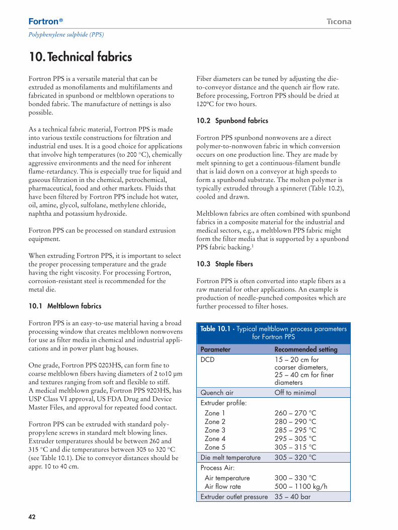
42
Fortron®
Polyphenylene sulphide (PPS)
Fortron PPS is a versatile material that can beextruded as monofilaments and multifilaments andfabricated in spunbond or meltblown operations tobonded fabric. The manufacture of nettings is alsopossible.
As a technical fabric material, Fortron PPS is madeinto various textile constructions for filtration andindustrial end uses. It is a good choice for applicationsthat involve high temperatures (to 200 °C), chemicallyaggressive environments and the need for inherentflame-retardancy. This is especially true for liquid andgaseous filtration in the chemical, petrochemical,pharmaceutical, food and other markets. Fluids thathave been filtered by Fortron PPS include hot water,oil, amine, glycol, sulfolane, methylene chloride,naphtha and potassium hydroxide.
Fortron PPS can be processed on standard extrusionequipment.
When extruding Fortron PPS, it is important to selectthe proper processing temperature and the gradehaving the right viscosity. For processing Fortron,corrosion-resistant steel is recommended for themetal die.
10.1 Meltblown fabrics
Fortron PPS is an easy-to-use material having a broadprocessing window that creates meltblown nonwovensfor use as filter media in chemical and industrial appli-cations and in power plant bag houses.
One grade, Fortron PPS 0203HS, can form fine tocoarse meltblown fibers having diameters of 2 to10 µmand textures ranging from soft and flexible to stiff.A medical meltblown grade, Fortron PPS 9203HS, hasUSP Class VI approval, US FDA Drug and DeviceMaster Files, and approval for repeated food contact.
Fortron PPS can be extruded with standard poly-propylene screws in standard melt blowing lines.Extruder temperatures should be between 260 and315 °C and die temperatures between 305 to 320 °C(see Table 10.1). Die to conveyor distances should beappr. 10 to 40 cm.
Fiber diameters can be tuned by adjusting the die-to-conveyor distance and the quench air flow rate.Before processing, Fortron PPS should be dried at120ºC for two hours.
10.2 Spunbond fabrics
Fortron PPS spunbond nonwovens are a directpolymer-to-nonwoven fabric in which conversionoccurs on one production line. They are made bymelt spinning to get a continuous-filament bundlethat is laid down on a conveyor at high speeds toform a spunbond substrate. The molten polymer istypically extruded through a spinneret (Table 10.2),cooled and drawn.
Meltblown fabrics are often combined with spunbondfabrics in a composite material for the industrial andmedical sectors, e.g., a meltblown PPS fabric mightform the filter media that is supported by a spunbondPPS fabric backing.1
10.3 Staple fibers
Fortron PPS is often converted into staple fibers as araw material for other applications. An example isproduction of needle-punched composites which arefurther processed to filter hoses.
10.Technical fabrics
Table 10.1 · Typical meltblown process parametersfor Fortron PPS
Parameter Recommended settingDCD 15 – 20 cm for
coarser diameters,25 – 40 cm for finerdiameters
Quench air Off to minimalExtruder profile:Zone 1 260 – 270 °CZone 2 280 – 290 °CZone 3 285 – 295 °CZone 4 295 – 305 °CZone 5 305 – 315 °C
Die melt temperature 305 – 320 °CProcess Air:Air temperature 300 – 330 °CAir flow rate 500 – 1100 kg/h
Extruder outlet pressure 35 – 40 bar

10
43
Fortron®
Polyphenylene sulphide (PPS)
Fortron PPS staple fibers in various deniers and crosssections in monocomponent and bicomponent fiberformats have been used as felt substrates, e.g., inneedlepunched composites. Multifilament Fortronyarns have also been made for industrial applicationsneeding woven textile structures.
10.4 Monofilament
Fortron PPS monofilaments, primarily made fromFortron 0214B1, 0317 and 0320, are used in wovenfabrics and in forming fabrics in paper machines (Fig. 10.1). In processing, monofilament diameter mustbe controlled carefully because weave consistencydepends on having a uniform diameter.
In producing monofilaments, the melt is extrudedthrough a monofilament die and cooled (Table 10.3).The monofilament then passes through draw-rollerassemblies to gain high tenacity. As the monofilamentexits the first draw assembly, it is heated and passedthrough a second one running at a different linearspeed. It then passes through a third draw assemblywhere it is spooled.
10.5 Multifilaments
Fortron PPS monofilaments, primarily made fromFortron 0320C0, are used in multifilaments. In pro-cessing, multifilament diameter must be controlledcarefully because weave consistency depends onhaving a uniform diameter.
Table 10.2 · Typical spundond processparameters
Parameter Recommended ValuesExtruderZone 1 274 °CZone 2 285 °CZone 3 296 °CZone 4 310 °CZone 5 320 °CDie melt 320 °C
Calendar, 107/107 °Cengraved/smooth
Basis weight, g/m2 34.0 – 68.0 g/m2
Table 10.3 · Typical monofilament processparameters
Parameter ValueExtruder average temperature 300 – 320 °CFlange temperature 300 – 310 °CHead temperature 300 – 310 °CMelt temperature 300 – 310 °COven temperature 140 – 210 °CDraw ratio 3 – 4Pack pressure 25 – 100 kg/cm2
Air Quench Yes
Fig. 10.1 · Drying belts made from monofilaments using Fortron PPS 0320C0

44
Fortron®
Polyphenylene sulphide (PPS)
Fortron® PPS 0320C0 enables the production of verytough and high tenacity multifilaments.
Their temperature resistance up to 170 °C and chemi-cal resistance make them suitable for rubber vulcani-sation. Several trials have shown the compatibility of Fortron® PPS and conventional elastomers andadditives used in the automotive industry.
The combination of Fortron® PPS multifilaments andrubber leads to a very good flexibility of the rubberhoses. Fortron® PPS multifilaments combine hightenacity and required elongation to allow the radialexpansion of the hoses according to volume and pres-sure increases. The dimensional stability of Fortron0320C0 ensures a very good and uniform shrinkagebehaviour of the multifilaments (shrinkage below 1 %).
References
1. 2003, Chemical Economics Handbook, SRIInternational
2. Kirk-Othmer Encyclopedia of ChemicalTechnology, 4th ed., vol. 17, John Wiley & Sons,1996, pp. 336-368.

10
11
45
Fortron®
Polyphenylene sulphide (PPS)
Manufacturers have many choices when it comes tothe assembly and finishing of Fortron PPS parts.Selecting among them involves an informed decisionthat balances design, the grade used, end use and otherpractical considerations to gain the greatest efficiencyat the lowest cost.
11.1 Annealing
Fortron PPS parts processed with mold wall tempera-tures ≥140 °C are well crystallized. They shrink littlewhen exposed to high temperatures afterward,so annealing to counter post-molding shrinkage effectsis not needed (Fig. 11.1).
A test of post-shrinkage on Fortron PPS parts with a 3 mm wall thickness made at mold temperatures of 140 °C showed that the 11401L4 and 6165A4 gradeshad just 0.09% and 0.10% shrinkage when annealedfor 2 hours at 230 °C, respectively. Similarly, shrink-age for these grades was 0.10% and 0.12% whenannealing occurred at 230 °C for 24 hours.
Strain at break, tensile strength and heat deflectiontemperature of annealed (3 hours at 200 °C) and non-annealed samples of Fortron 1140L4 as a function ofmold wall temperature appear in Figure 11.2, 11.3 and11.4. These show the critical importance of higher moldwall temperatures in minimizing post-mold shrinkageand optimizing mechanical and thermal properties.
11.Assembly and finishing
Fig. 11.1 · Shrinkage of Fortron 1140L4 tensiletest bars (ISO 3167) as a function of mold walltemperature, annealing conditions: 3 h, 200 °C
0 20 40 60 80 100 120 140 °C 180
Mould wall temperature
Shrin
kage
mould shrinkage
total shrinkageafter annealing
Fig. 11.2 · Relation between tensile strength andmold wall temperature of annealed and
non-annealed samples of Fortron 1140L4
0 20 40 60 80 100 120 140 °C 180
Mould wall temperature
annealed samples
220MPa210
200
190
180
170
Tens
ile s
treng
th
non-annealed samples
Fig. 11.4 · Relation between heat deflection temperature HDT/C and mold wall temperature
of annealed and non annealed samplesof Fortron 1140L4
0 20 40 60 80 100 120 140 °C 180
Mould wall temperature
annealed samples250°C
200
150
100
50Hea
t def
lect
ion
tem
pera
ture
HD
T/C
non-annealed samples
Fig. 11.3 · Relation between strain at break and mold wall temperature of annealed and
non-annealed samples of Fortron 1140L4
0 20 40 60 80 100 120 140 °C 180
Mould wall temperature
annealed samples
4%3
2
1
0
Stra
in a
t bre
ak
non-annealed samples
46
Fortron®
Polyphenylene sulphide (PPS)
11.2 Machining
Fortron PPS can be machined with the same routers,sanders, saws, lathes and other tools used for metal or wood. Injection molded parts are machined to addfeatures that are uneconomical to mold or that cannotbe molded with enough precision, or if there is a needto avoid critical welds. Extruded Fortron PPS shapesare also machined to form components for manyapplications.
When machining Fortron PPS:
– Keep tools sharp and cool to avoid excessivefrictional heat so the plastic does not distort, meltor lose its finish.
– Account for the resin’s low thermal conductivity in selecting machining conditions. At high cuttingspeeds, cool tools with clean, compressed air orconventional cutting fluids, e.g., water, aqueoussolutions, ethylene glycol or oil-based fluids.Adjust speed and feed rate according to how theplastic responds, e.g., reduce speed if melting,burning or discoloration occurs.
– Remove chips for optimal cooling. Chips that occurwith reinforced or filled Fortron PPS tend to beshort and easily removed.
– Recommended cutting speeds vary with the equip-ment involved, e.g., 50 to 200 m/min for drilling,250 to 500 m/min for turning and milling, and 500to 800 m/min for sawing. Recommended feed ratesalso vary with the process, e.g., 0.1 to 0.5 mm/revfor turning and 0.1 to 0.3 mm/rev for drilling. Toolwear increases at lower feed rates and can impairthe quality of the cut surfaces.
– Avoid burr formation in thread cutting by usingdouble-toothed chasers. Also use a diameter-dependent overmeasure with screw taps. Avoidcutting dies because they are likely to continuecutting on the return.
– Machining glass-fiber-reinforced or mineral-filledFortron PPS grades is best done with carbide- ordiamond-tipped tools, especially for high-volumeproduction. Tools made of high-speed steel arelikely to have a shorter service life.
– In turning, clearance angles of 6 to 8°, rake anglesof 0 to 5°, and cutting edge angles of 45 to 60° arerecommended. To gain a smooth cut, increase thecutting profile radiused by at least 0.5 mm.
– In milling, use standard milling cutters having fewteeth to gain a larger chip space. This permits a
large chip volume so the heat generated is removedwith the chips. Clearance angles of 5 to 15° andrake angles of 6 to 10° have proven successful.
– Drilling and reaming are used to enlarge, deepen orremove draft from holes. Bits designed for plasticsgive the best results. These usually have one or twopolished or chrome-plated flutes, narrow lands andlarge helix angles so they expel chips quickly andminimize friction. Bits should be sharp and may needto be withdrawn often in deep holes to eject chips.
– When using metalworking twist drills, it is best tohave twist angles of 12 to 16°, clearance angles of 5 to 10°, rake angles of 10 to 30° and cutting edgeangles of 90°. For deep holes, ensure adequate chipremoval, e.g., smooth helical grooves. Pilot drilling of large diameters is recommended.
– Avoid unnecessary heat build-up from friction insawing by using a thin saw blade. Use a toothgeometry with a clearance angle of 15 to 30°, a rakeangle of 0 to 5°, and tooth pitch of 3 to 5 mm.
11.3 Assembly of Fortron moldings
Fortron PPS components can be produced separatelyand then assembled by a variety of thermal, adhesiveand mechanical methods.
11.3.1 Thermal welding
In thermal welding, the bond line between twoparts is melted to form a weld. This method is a fast,economical and safe way to join Fortron PPSelements. Manufacturers can choose from amongultrasonic welding, spin welding, vibration welding,hot-plate welding, induction welding and laserwelding.
The best welding strength occurs with high-qualitycomponents that are based on well-designed and well-molded parts having close tolerances and gooddimensional stability. The choice of method for anapplication is governed by joint shape and design,Fortron grade, and part profile.
– Ultrasonic welding, which applies high-frequencyenergy at the interface between parts normallytakes less than 2 seconds per weld. It forms con-tinuous, leak-proof joints between Fortron PPS

11
47
Fortron®
Polyphenylene sulphide (PPS)
elements that that can be as strong as the PPS itself(Fig. 11.5). Pinch-off welds formed at 20 to 40 kHzare often optimal, although tapered pinch weldshaving a welding distance of over 1 mm are alsoviable.
Fortron PPS is suitable for near- and far-field ultra-sonic welding. The alternating strains absorbedby PPS in ultrasonic welding can cause localizeddamage. Avoid this by designing the weld properlyand by optimizing welding, time, pressure and othermachine settings. Fortron grades with reinforce-ment loading to 40% give good welding results.Weldability deteriorates above this level.
– Spin welding joins parts having rotationally sym-metrical joint faces. It calls for relatively simpleequipment that holds one part steady and whilepressing a rotating part against it at a set pressure.With Fortron PPS, gas-tight, high-strength weldsusually forms in less than 3 seconds. Welding con-ditions, such as surface speed, contact pressuresand rotational speeds, depend on grade and partgeometry, and should be defined in optimizingtrials.
– Vibration welding rubs parts together to createfrictional heat, usually at amplitudes of 2.5 to 5 mmand frequencies of 120 and 240 Hz. This methodforms strong joints quickly and works best withlarge parts that have irregular joint interfaces. It isan excellent alternative if part geometry or size donot allow for ultrasonic or spin welding.
– Hot-plate welding works well for joints exposedto mechanical stress in service, large joint surfacesor part geometries that preclude other weldingmethods. The hot tools used must be designed forthe high temperatures needed in working with PPS.
– Induction or electromagnetic welding excitesfine, magnetically sensitive metallic or ceramic par-ticles in a preform with a radio-frequency magneticfield. Heat induced in the preform placed at thejoint fuses Fortron PPS parts as they are pressedtogether to form gas-tight, high-strength joints.Induction welding allows the insertion of metalparts and can be used for difficult joints whereother methods fail.
– Laser welding transmits a light beam through onepart so it is absorbed and heats the surface of asecond part. With Fortron PPS, the laser permeablepart should be made of an unfilled grade and lessthan 2 mm thick. The other element should bemade of reinforced Fortron PPS because thesegrades have good absorption behavior. Consultwith the laser welding system manufacturer whencarrying out trials for this method.
11.3.2 Snap-fits and other molded-in features
Fortron PPS has limited suatability for snap fits.The design of Fortron PPS snap-fit joints1 shouldaccount for how permissible outer-fiber strain dependson wall thickness, as well as for the orientation of theglass fiber. Guide values for the upper limit of outer-fiber strain are:
Fig. 11.5 · Load bearing capacity of ultrasonically welded test specimens produced from
various Fortron grades
1130L4 1140L4 6165A41140L6 6165A6
Frequency 20 kHz Welding time 0.8 sAmplitude 30 µm Weld design single pinch weldWelding force 400 N Generator output 700 W
not weldedwelded
min. 0.05 mm
0.05–0.1 mm
30–45° R
melta
6,000N
5,000
4,000
3,000
2,000
1,000
0
Brea
king
stre
ss

48
Fortron®
Polyphenylene sulphide (PPS)
Fortron PPS 1131L4 ITT, 1140L4, 1140L6: 1.3%Fortron PPS 4184L4, 4184L6: 1.1%Fortron PPS 6165A4, 6165A6: 0.8%
The friction factor needed for the calculation dependson the sliding partners, surface roughness and surfacepressure. Typical friction factors with Fortron PPS are0.3 to 0.4 for Fortron on Fortron and 0.4 for FortronPPS on steel. Trials are recommended for snap-fitsand other molded-in assembly features.
11.3.3 Adhesive bonding
Fortron PPS is bonded through contact adhesion.The process is fast, economical and requires little orno part preparation or special equipment. It alsocreates excellent liquid and gas seals and causes noassembly stresses.
Depending on the application, two-part adhesivesbased on epoxy resin, methacrylate or polyurethaneand one-part adhesives based on cyanoacrylate or hotmelt adhesives can be used. Select the adhesive basedon end-use service temperature. Joint surfaces shouldbe free of grease, mold release compound and othercontaminants that can spoil a bond and may need tobe roughened or etched.
Joints for adhesive bonding can take many forms and should be tested in use. Close contact with theadhesives industry is recommended during adhesivetrials.
11.3.4 Screws and other mechanical fasters
Fortron PPS can be used with molded threads,molded-in inserts, and bolting with through bolts anddirect bolts (e.g., self-tapping screws). The methodchosen depends on end-use requirements and partdesign. Fortron PPS expands little and is sensitive tonotches, so areas of the part likely to be stressedduring the attachment of mechanical fasteners shouldbe carefully designed. Stress can also be limited byselecting the appropriate fastener and use of torque-limiting drivers during assembly. Be sure to consultfastener makers during trials.
Threaded metal inserts permanently installed inmolded bosses eliminate the need for a nut, so assemblycan be done from one side. These can involve femalethreads, threaded male studs, locating pins and bush-ings. Ultrasonically installed inserts are strong andrelatively free of stress compared to many other typeof inserts.
When using self-tapping screws, size the hole properlyto avoid excessive hoop stress in the boss. Also, makethe hole deep enough so the screw does not bottomout and make the wall of the boss thick enough toresist the stress created by the screw.
Metal rivets create permanent assemblies that installrapidly. The rivets used should have large heads sothey spread the load. Form the rivet against the metalpart of the assembly or against a metal washer, if theparts being joined are made of plastic.
11.4 Finishing
Manufacturers can turn to many surface finishingmethods to improve appearance, add identifyingmarks and protect against heat, radiation, chemicals,electromagnetic noise and abrasion. These methodsinclude laser marking, painting, printing and metalliza-tion.
Such methods often call for pretreatment, becausefinishing is usually most effective when surfaces arefree of oil, mold release agents and other contaminants.Cleaning often involves solvents and detergents,although surface preparation using primers, etching,sanding, flame treatment and other methods may beneeded.
11.4.1 Laser marking
Non-contact marking of text, patterns, symbols andcodes on Fortron PPS surfaces uses a Nd:YAG laser(at 1064 nm). These lasers produce dark, matt markson Fortron PPS.

11
49
Fortron®
Polyphenylene sulphide (PPS)
11.4.2 Painting
Articles made from Fortron can be painted usingconventional topcoat systems after pretreatment witha suitable primer. The choice of system depends onthe properties needed, e.g. weathering resistance,chemical resistance or scratch resistance. It is impor-tant to ensure the paint system can cope with thethermal stresses involved in an end use.
11.4.3 Printing
Printing on Fortron PPS can be done via gravure, flex-ographic, pad, offset, screen, digital and other methods.Before printing, the surface must be pretreated so it is free of grease. Depending on the application, inksbased on epoxy resin, acrylic resin, cellulose ester ortwo-pack inks based on urethane can be used.
11.4.4 Metallization
Fortron PPS parts can be metallized by wet- or electroanalysis and vacuum metallizing. Since a flawless partsurface is essential for metallization, the mold must bewell vented during processing.
In electroplating, Fortron PPS parts are acid etched tocreate microporous surfaces that improve electroplateadhesion. A thin layer of copper or other metal isdeposited by immersing parts into an electrolyte bath.Next, the electroplate is formed as a relatively thick,durable layer of such metals as copper, nickel, chrome,brass, silver or gold. Parts should be smooth andwithout such flaws as weld lines and sink marks.
11.4.5 Heat-based processes
Hot stamping uses raised-image dies to transfer letter-ing and designs ranging from solid colors, woodgrains, metallic finishes and other effects from foils or tapes. The die is heated to near the melting point of the plastic. Heat transfer uses a heated flat die orroller to bond multicolor designs onto the surfacefrom a composite film.
References
1. Ticona GmbH, Design Calculations for snap fitjoints in plastic parts. Issued in August 1996 / 2nd
Edition. © 2004 Ticona GmbH, Kelsterbach

50
Fortron®
Polyphenylene sulphide (PPS)
Abrasion 16Adhesive bonding 48Annealing temperature 26, 45Assembly 45, 46Automotive fluids 18
Back pressure 30Balanced filling 27Barrel residence time 30Blow molding 3, 39Blow molding machine, 3D 39Bolting 48Bubbles in molded part 34Burn marks 32
CAP fuel 18Clamping force 24Coefficient of Linear Thermal Expansion 13Color concentrate 5Combustion 14Composites 39Continuous service temperature 12, 17Coolng time, theoretical 30Creap rapture test 7Crosshead die 38Cutting speed 46
Deflection temperature (DTUL) 12Dimensional stability 7Discoloration 32Dissipation factor 15Draft 26Drilling 46
Ejection angle 27Ejection surface 27Electrical insulation 15Electrical properties 8Electrical strength 16Electromagnetic welding 47Extrusion 35Extrusion coating 37Extrusion, head 35Extrusion, processing conditions 35Extrusion, screen pack 35Extrusion, screw design 35
Fatigue Strength 11Fiber 3Filled grades 4Film 3Finishing 45, 48Flame retardance 7Flammability 14Flash reduction 32Flexural creep modulus 9Fuel 18
Gate 27Gate diameter 27Gate, drooling 34Gate, freezes off 34Glass transition (Tg) 9
Hard metal alloys 26High voltage stress 16Holding pressure time 30Holding pressure, specific 30Hot plate welding 47Hot runner 29Hot runner, nozzle 29Hot stamping 49Hot wire test 14Hydrolysis 18Hygroscopy 18
Inductive welding 47Injection molding 24Injection molding machine 24Injection molding processing conditions 30Injection pressure, specific 30
Laser marking 48Laser welding 47
Machining 46Mechanical properties 7,8Melt temperature 30Meltblown fabrics 42Metal rivets 48Metallization 49Milling 46Moisture absorption 7
12. Subject Index

51
Fortron®
Polyphenylene sulphide (PPS)
12
Mold design 25Mold temperature 24Mold wall temperature 30Molded threats 48Molded-in inserts 48Monofilament 43Multifilaments 43
Nozzle drool 32Nozzle with tips 29Nozzle, free flow 29Nozzle, freeze-off 32Nozzle, needle shut-off 29Nozzle, side gating 29
Painting 49Part Distortion 33Pellets, unmelted 33Physical properties 7Pipe wxtrusion 36Pit marks 33Power coating 41Precristallization temperature (Tcc) 12Printing 49Process parameters, injection molding 29Process parameters, meltblown 42Process parameters, monofilament 43Process parameters, spunbond 43Processing temperature 5Profile extrusion 3Purging 30
Quality management 6
Radii 28Recristallization temperature (Trc) 12Regrind, use of 31Relative permittivity 15Ribs 28Rockwell hardness 16Rods 36Runner 27Runner, full round 27Runner, trapezoidal 27
Sawing 46Screw speed 30Screws 48Screws, self tapping 48Short Shots 33Shot weight, recommended 30Shrinkage 45Sinks 33Slabs 36Sliding 16Smoke Gas Density 15Snap fits 47Soldering 14Spin welding 47Sprue 27Spunbond fabrics 42Standards
– ABD 14– Automotive Specs GADSL 21– Automotive Specs GMP 21– Automotive Specs IMDS 21– Automotive Specs MS-DB 21– Automotive Specs WSL WSF 21– BfR 22– BgVV, BGA 22– CAS 22– Drinking Water DE KTW 21– Drinking Water FR ACS 21– Drinking Water UK WRAS 21– Drinking Water US NSF 22– FAR 14– FCN 22– FDA 4– ISO 9000 6– National Bureau of Standards NFPA 208 14– Rail 15– RoHS 14– SAE 18– SML 22– US Vehicle Safety Standard FMVSS 302 14– WEEE 14
Staple fibers 42Sticking problems 33Stress relaxation test 7

52
Fortron®
Polyphenylene sulphide (PPS)
Surface resistivity 15Surface ripples 33
Taper 27Technical fabrics 42Thermal conductivity 13Thermal properties 8Thermal welding 46Tolerances 28Tool steels 25Toxicity 15Treatment temperature 26Tribology 16Troubleshooting guidelines 32Tube Extrusion 36Turning 46
Ultrasonic welding 46Undercut 26Undercut depth, maximum 27Unreinforced 4UV Resistance 19
Venting 27Voids 33Volume resistivity 15
Warpage 33Weld line 28Weld line integrity 34Wire coating 37Wöhler curve 11, 12

53
Fortron®
Polyphenylene sulphide (PPS)
Conversion
11.1 · Unit conversion factorsMultiply byDivide by
LengthInch (in) 0.0254 Meter (m)Foot (ft) 0.305 Meter (m)
AreaSquare inch (in2) 6.45 x 10⁻⁴ Square meter (m2)Square feet (ft 2) 0.0929 Square meter (m2)
VolumeCubic inch (in3) 1.64 x 10⁻⁵ Cubic meter (m3)Cubic feet (ft 3) 0.0283 Cubic meter (m3)
MassPound (lb) 0.454 Kilogram (kg)
ForcePound force (lbf) 4.45 Newton (N)Kilogram force (lbf) 9.81 Newton (N)
PressureNewton/meter2 (N/m2) – Pascal (Pa)lbf/in2 (psi) 6.897 x 10³ Pascal (Pa)lbf/in2 (psi) 6.897 x 10⁻³ Mega Pascal (MPa)kg/cm2 9.81 x 10⁴ Pascal (Pa)bar 104 Pascal (Pa)
ViscosityPoise 0.1 Pascal · second (Pa · s)
EnergyCalorie (cal) 4.2 Joule (J)Calories/gram (cal/g) 4.2 Kilojoule/kilogram (kJ/kg)Joule/kilogram (J/kg) 2.33 x 10³ BTU/lb
Technical fabrics
Yarn size1 tex 9 Denier1 dtex 0.1 mg/m
Tenacity1 cN/tex 0.1132 gf/denier
11.2 · Tensile or flexural property conversionStrength Modulus
MPa psi MPa psi x 106
75 10,900 6,000 0.87100 14,500 8,000 1.16125 18,000 10,000 1.45150 21,800 12,000 1.74175 25,400 14,000 2.03200 29,000 16,000 2.32225 32,700 18,000 2.61250 36,300 20,000 2.90275 39,900 22,000 3.19300 43,500 24,000 3.48
11.3 · Length Conversioninches inches mils cm mm
1 1 1000 2.54 25.41/2 0.5 500 1.27 12.71/4 0.25 250 0.635 6.351/8 0.125 125 0.32 3.21/16 0.0625 62.5 0.16 1.61/32 0.0313 31.3 0.08 0.81/64 0.0156 15.6 0.04 0.4
11.4 · Temperature ConversionDegrees Centigrade (°C) Degrees Fahrenheit (°F)
0 3210 5020 6850 12275 167
100 212125 257150 302175 347200 392225 437250 482275 527300 572325 617350 662375 707400 752
Conversion factor: °F = 1.8 (°C) + 32

54
Fortron®
Polyphenylene sulphide (PPS)

55
Fortron®
Polyphenylene sulphide (PPS)
Notice to users:
To the best of our knowledge, the information con-tained in this publication is accurate, however we donot assume any liability whatsoever for the accuracyand completeness of such information. The informa-tion contained in this publication should not be con-strued as a promise or guarantee of specific propertiesof our products.
Further, the analysis techniques included in thispublication are often simplifications and, therefore,approximate in nature. More vigorous analysistechniques and prototype testing are strongly recom-mended to verify satisfactory part performance.Anyone intending to rely on any recommendationor to use any equipment, processing technique ormaterial mentioned in this publication should satisfythemselves that they can meet all applicable safety andhealth standards.
It is the sole responsibility of the users to investigatewhether any existing patents are infringed by the useof the materials mentioned in this publication.
Properties of molded parts can be influenced by a widevariety of factors including, but not limited to, materialselection, additives, part design, processing conditionsand environmental exposure. Any determination of thesuitability of a particular material and part design forany use contemplated by the users is the sole respon-sibility of the users. The user must verify that the mate-rial, as subsequently processed, meets the requirementsof the particular product or use. The user is encouragedto test prototypes or samples of the product under theharshest conditions likely to be encountered to deter-mine the suitability of the materials.
Material data and values included in this publicationare either based on testing of laboratory test specimensand represent data that fall within the normal range ofproperties for natural material or were extracted fromvarious published sources. All are believed to be repre-sentative. These values alone do not represent a suffi-cient basis for any part design and are not intendedfor use in establishing maximum, minimum, or rangesof values for specification purposes. Colorants or otheradditives may cause significant variations in datavalues.
We strongly recommended that users seek and adhereto the manufacturer’s current instructions for handlingeach material they use, and to entrust the handlingof such material to adequately trained personnel only.Please call the numbers listed on the back cover foradditional technical information. Call CustomerServices at the number listed overleaf for the appro-priate Material Safety Data Sheets (MSDS) beforeattempting to process these products. Moreover, thereis a need to reduce human exposure to many materialsto the lowest practical limits in view of possible adverseeffects. To the extent that any hazards may have beenmentioned in this publication, we neither suggestnor guarantee that such hazards are the only ones thatexist.
The products mentioned herein are not intended foruse in medical or dental implants.
© Copyright by Ticona GmbH
Published in May 2007

56

Hostaform®, Celcon®
polyoxymethylene copolymer (POM)
Celanex®
thermoplastic polyester (PBT)
Impet®thermoplastic polyester (PET)
Vandar®
thermoplastic polyester alloys
Riteflex®
thermoplastic polyester elastomer (TPC-ET)
Vectra®
liquid polymer (LCP)
Fortron®
polyphenylene sulphide (PPS)
Celstran®, Compel®long fiber reinforced thermoplastics (LFRT)
GUR®
ultra-high molecular weightpolyethylene (PE-UHMW)
Contact Information
Americas
TiconaProduct Information Service8040 Dixie HighwayFlorence, KY 41042USATel.: +1-800-833-4882Tel.: +1-859-372-3244email: [email protected]
Customer Service
Tel.: +1-800-526-4960Tel.: +1-859-372-3214Fax: +1-859-372-3125 B
240
BR G
B-05
.200
7
Fort
ron
®Po
lyph
enyl
ene
sulp
hide
(PPS
)
Europe
Ticona GmbHInformation ServiceProfessor-Staudinger-Straße65451 KelsterbachGermanyTel.: +49 (0)180-584 2662 (Germany)*
+49 (0)69-305 16299 (Europe)Fax: +49 (0)180-202 1202**email: [email protected] on the web: www.ticona.com
** 0,14 1/min + local landline rates** 0,06 1/call + local landline rates