FortisAlberta Service and Metering Guide
94
FortisAlberta Service and Metering Guide November 2015, Version 4.0
Transcript of FortisAlberta Service and Metering Guide
FortisAlberta Service and Metering Guide
November 2015, Version 4.0
FortisAlberta
Alberta Service and Metering Guide
Revision Date: November 2015 Version No.: 4.0
This document is the property of FortisAlberta for authorized used only. This is an uncontrolled printed copy (printed on 2015/11/12 at 4:44 PM) and may be out of date. See the electronic copy of this document on the FortisAlberta web site at fortisalberta.com for the current official version.
Page 2 .
Table of Contents
Glossary …………………………………………………………………………….4
1.0 Introduction ..................................................................................... 6 1.1 Disclaimer ........................................................................................... 6
2.0 Codes & Requirements ................................................................... 7 2.1 Lot Line Metering .............................................................................. 10 2.2 Safety Codes Act and Associated Regulations ................................ 10 2.3 Access to Metering Equipment ......................................................... 10 2.4 CSA Approved Device and Meter Socket Requirements ................. 11 2.5 Service Entrance Equipment Requirements .................................... 11 2.6 Customer owned poles ..................................................................... 11 2.7 Electrical Equipment Room Requirements....................................... 11 2.8 Customer Instrumentation and Protection ........................................ 12 2.9 Disconnects and Reconnects ........................................................... 12 2.10 Modifications to Existing Services .................................................... 13 2.11 Standard FortisAlberta Supply Voltages .......................................... 13 2.12 Customer owned Secondary Cable Voltage Drop Requirements .... 13 2.13 Three-Phase Services ...................................................................... 14 2.14 Services That Do Not Require Metering ........................................... 14 2.15 Self-Contained Metering ................................................................... 14 2.16 Instrument Metering .......................................................................... 21
3.0 Non-Standard Services ................................................................. 26
4.0 Residential Services ..................................................................... 27 4.1 Overhead Service Supplied by an Overhead Transformer .............. 27 4.2 Underground Service Supplied by an Overhead Transformer ......... 27 4.3 Underground Service Supplied by a Padmount Transformer .......... 30 4.4 Multiple Residential Service Sites .................................................... 30
5.0 Farm/Rural Services ..................................................................... 31 5.1 Overhead Farm Service Supplied by an Overhead Transformer ..... 31 5.2 Underground Farm Service Supplied by an Overhead Transformer 31 5.3 Underground Farm Service Supplied by a Padmount Transformer . 32
6.0 Transfer Switches and Standby Generators ................................. 32
7.0 Commercial Services .................................................................... 34 7.1 Overhead Service Supplied by an Overhead Transformer .............. 34 7.2 Underground Service Supplied by an Overhead Transformer ......... 35 7.3 Underground Service Supplied by a Padmount Transformer .......... 37 7.4 Metering Requirements for less than 300V Services ....................... 39 7.5 Metering Requirements for Greater than 300V, Services ................ 39 7.6 Instrument Metering Requirements .................................................. 40
8.0 Metering Signal Service Offer ....................................................... 42 8.1 Availability of metering signals ......................................................... 42
FortisAlberta
Alberta Service and Metering Guide
Revision Date: November 2015 Version No.: 4.0
This document is the property of FortisAlberta for authorized used only. This is an uncontrolled printed copy (printed on 2015/11/12 at 4:44 PM) and may be out of date. See the electronic copy of this document on the FortisAlberta web site at fortisalberta.com for the current official version.
Page 3 .
8.2 Process ............................................................................................. 42 8.3 Radio Frequency (RF) Communication Installation ......................... 42 8.4 Basic Digital Pulse and Wireless Signals Specification ................... 43 8.5 Communication specifications .......................................................... 43 8.6 Disclaimer ......................................................................................... 44
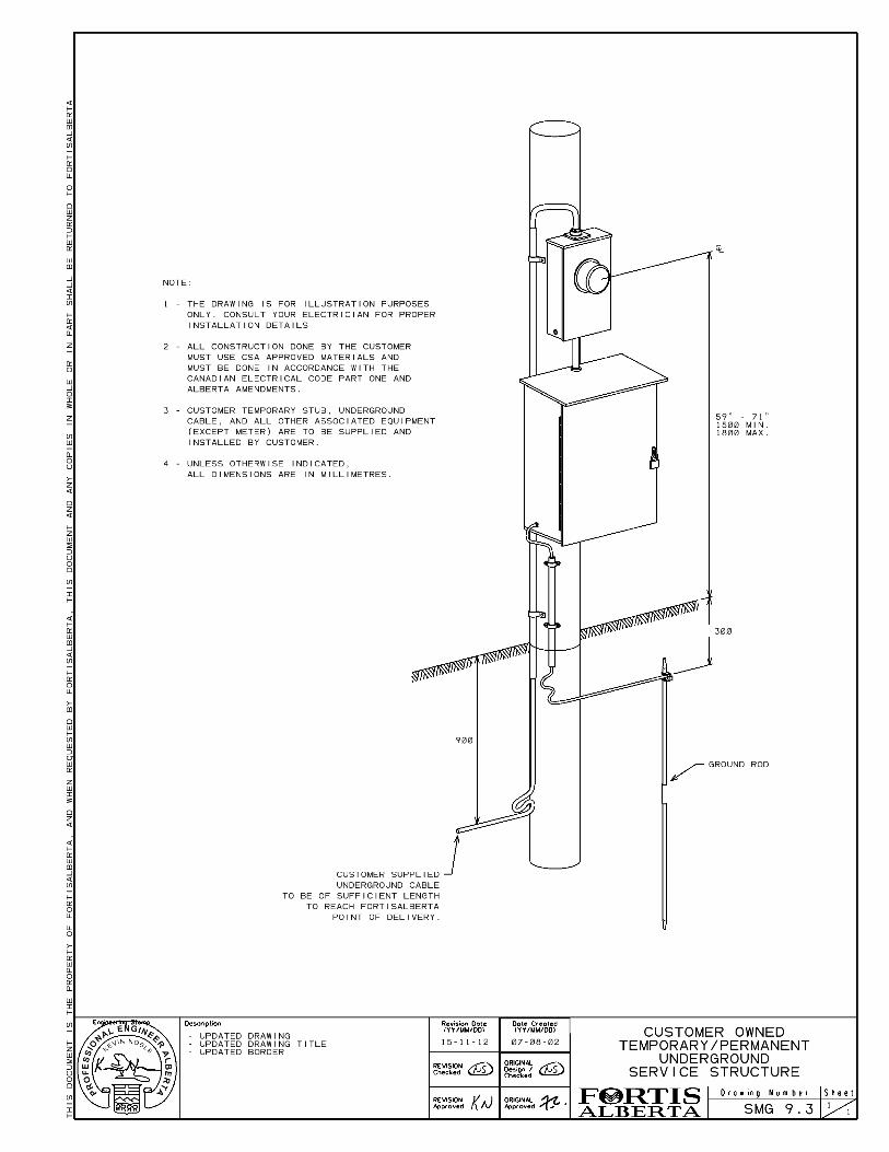
9.0 Temporary Services ...................................................................... 44 9.1 General requirements ....................................................................... 44 9.2 Overhead Services Supplied by an Overhead Transformer ............ 44 9.3 Underground Services Supplied by an Overhead Transformer ....... 45
10.0 Micro-Generation .......................................................................... 45 10.1 Micro-Generation Service Determination ......................................... 45 10.2 Type-A Responsibilities .................................................................... 46 10.3 Type-B Responsibilities .................................................................... 46 10.4 Type-C Responsibilities .................................................................... 49
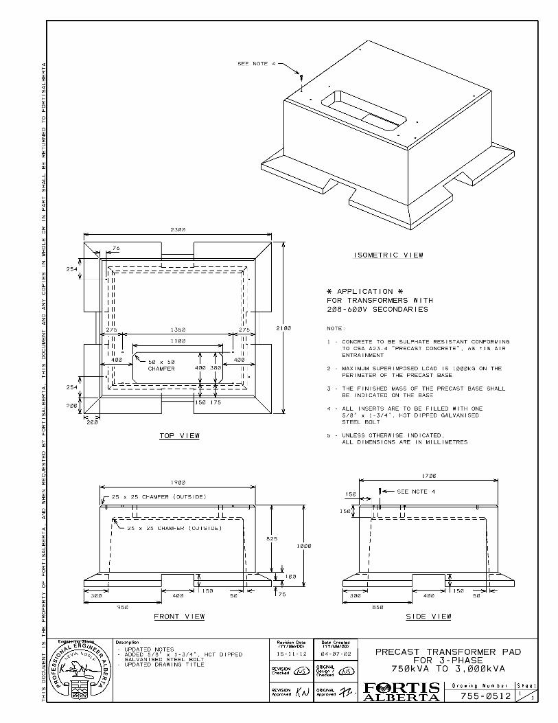
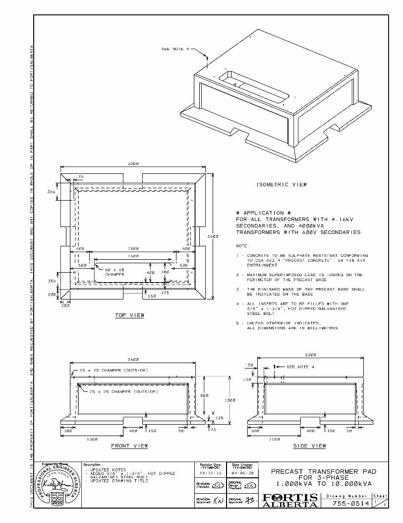
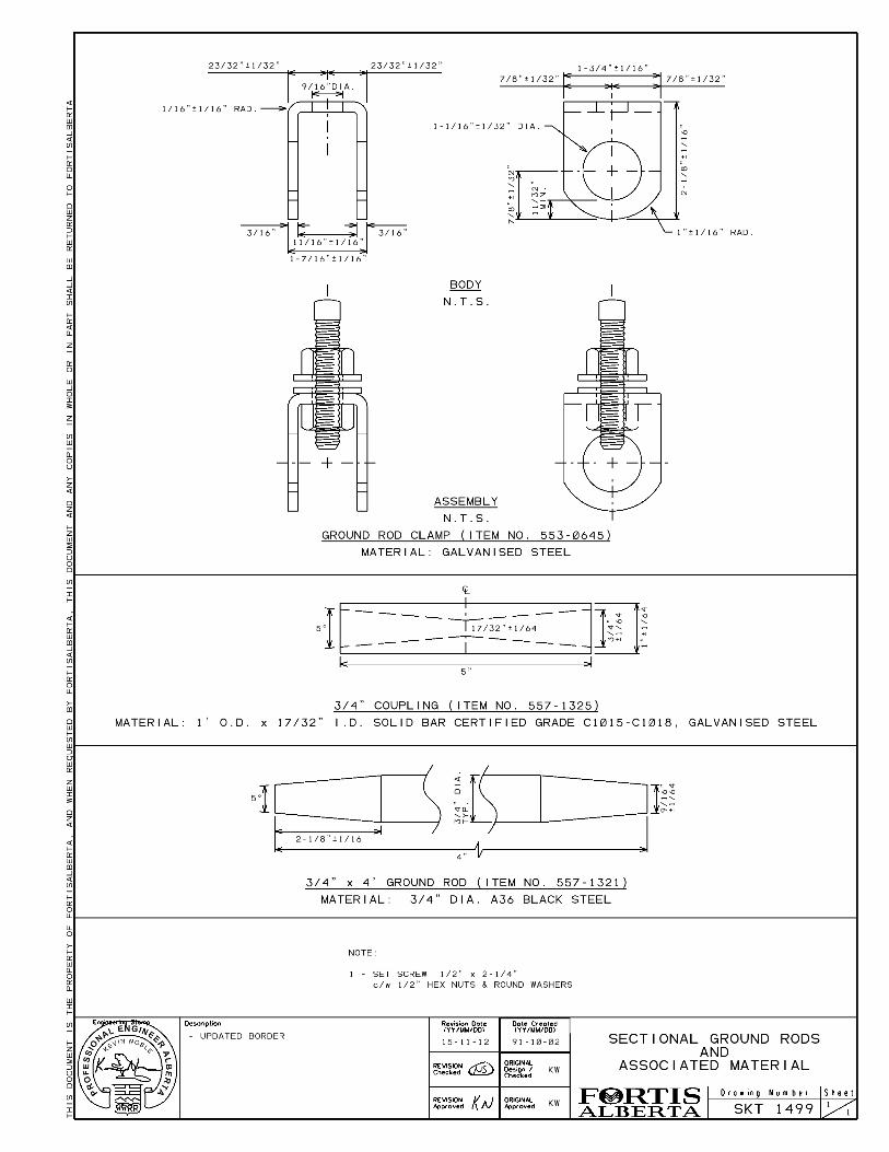
11.0 Material Specifications .................................................................. 49 11.1 Instrument Meter Socket Specifications ........................................... 49 11.2 Single Phase Pre-cast concrete bases ............................................ 50 11.3 Three Phase Pre-cast concrete bases ............................................. 51 11.4 Conduit materials .............................................................................. 52 11.5 Grounding material ........................................................................... 53
Appendix ‘A’ – Forms and Drawings .................................................................. 55 A.1 Forms................................................................................................ 55 A.2 Placement of Facilities...................................................................... 55 A.3 Pre-Cast Concrete Bases ................................................................. 55 A.4 Material ............................................................................................. 55 A.5 Padmount Transformer Civil and Grounding .................................... 56 A.6 Single Phase Service ....................................................................... 56 A.7 Three Phase Service ........................................................................ 56
FortisAlberta
Alberta Service and Metering Guide
Revision Date: November 2015 Version No.: 4.0
This document is the property of FortisAlberta for authorized used only. This is an uncontrolled printed copy (printed on 2015/11/12 at 4:44 PM) and may be out of date. See the electronic copy of this document on the FortisAlberta web site at fortisalberta.com for the current official version.
Page 4 .
All modifications to the previous version of the Alberta Service and Metering Guild are indicated by green text. This document can be searched by using the ‘ctrl+f’ search function in Adobe Acrobat Reader or similar products.
Glossary
CEC - Canadian Electrical Code, Part One (CSA Standard No. C22.1 - Latest Edition).
CSA - Canadian Standards Association.
CT Cabinet - The enclosure supplied and installed by the Customer for the housing of FortisAlberta current transformers.
Distribution connection point – An electrical line, at secondary or primary voltage (120 V up to 25kV) which is used to serve multiple Customers.
Farm – These services are generally single-phase 120/240 volt self-contained services supplying farming operations in rural areas that contains a residence and on which agricultural activities are conducted with the intent of deriving revenue.
Inspection Authority – local municipality or the province, or an accredited agency authorized to sign-off electrical permits.
Installed Capacity - The rated capacity in kilo-volt-amperes (kVA) of the FortisAlberta transformer supplying the service.
Instrument Transformers - High accuracy current or voltage transformers approved by Measurement Canada for revenue metering.
Instrument Transformer Enclosure - The enclosure supplied and installed by the Customer for the housing of instrument transformers.
Lot Line Metering – Metering that is located close to the front property line on a self-supporting structure.
Meter box, Farm and Rural - A meter mounting device that includes a meter socket and secondary breaker, which is attached to a pole or stub.
Meter, Instrument Type - A 20 Amp meter used in conjunction with instrument transformers (CT’s & PT’s).
Meter, Network - A two element meter designed for use on a three wire network service obtained from two phase wires and a neutral of a three phase, four wire, wye system.
Meter Pedestal - A meter mounting device that includes a meter socket and in some cases a breaker that is self-supporting.
FortisAlberta
Alberta Service and Metering Guide
Revision Date: November 2015 Version No.: 4.0
This document is the property of FortisAlberta for authorized used only. This is an uncontrolled printed copy (printed on 2015/11/12 at 4:44 PM) and may be out of date. See the electronic copy of this document on the FortisAlberta web site at fortisalberta.com for the current official version.
Page 5 .
Meter, Self-Contained - A meter rated for carrying the total current and full voltage of the circuit to be metered.
Meter Socket - A meter mounting device for the purpose of installing FortisAlberta's self-contained 200 Amp meter or instrument 20 Amp meter.
Multiple Meter Installation - Any installation where a building has several meters fed from one service entrance, such as apartment buildings, shopping centers, office buildings, warehouse or light industrial complexes.
Padmount Metering – Metering configuration that is designed to be mounted onto the side of the secondary compartment of an underground transformer that sits on a precast pad or vault.
Primary Metering – Metering configuration meters 25 kV voltage, supplying this voltage directly to the customer. Typically restricted to large industrial customers.
Residential – These services are generally single-phase 120/240 volt self-contained services to individual houses, apartment buildings or condominium complexes.
Service Disconnect and Main - An approved metal box or cabinet containing either service fuses and a service switch or a circuit breaker and of such design that either the switch or circuit breaker may be manually operated when the box is closed.
Service Entrance - means all that portion of the Customer's installation from the pedestal or its equivalent up to and including the point at which the supply authority makes connection.
Service, Temporary - Service for a limited period of time (generally less than one year). (Example: construction sites).
Service, Three Phase/Four Wire – All services are supplied as three phase conductors and a grounded neutral conductor to the service entrance, and on to the meter.
Single Phase Commercial – These services are generally single phase 120/240 or 240/480 volt self-contained services supplying typical businesses. This includes multi-family services with a commercial meter.
Three Phase Commercial - These Commercial and Industrial services are three phase services, which may use 120/208 volt self-contained metering or up to 2400/4160 volt instrument metering typically supplying industrial Customers. This includes oil and gas lease sites.
FortisAlberta
Alberta Service and Metering Guide
Revision Date: November 2015 Version No.: 4.0
This document is the property of FortisAlberta for authorized used only. This is an uncontrolled printed copy (printed on 2015/11/12 at 4:44 PM) and may be out of date. See the electronic copy of this document on the FortisAlberta web site at fortisalberta.com for the current official version.
Page 6 .
1.0 Introduction
This publication is for use by FortisAlberta’s Customers concerned with Residential, Farm and Commercial electrical installations within the FortisAlberta service area. The information within supersedes all information previously provided by FortisAlberta on the subject. Comments and questions can be submitted by e-mail to the Customer Interaction (CI) Group – ([email protected]). Customers should apply for service early in the planning stage of a project to help ensure that FortisAlberta can meet the Customers project time schedule and to ensure the installation will be satisfactory to both the inspection authority and FortisAlberta. Customers can arrange an inspection of an installation by contacting FortisAlberta toll-free at 310-WIRE (310-9473). This publication covers most of the possible Customer projects encountered on the FortisAlberta system. Customer projects that do not meet the requirements covered in this publication shall abide by “Section 3.0, Non-Standard Services”. All Customer supplied electrical equipment shall conform to CSA Standards. The Customer project shall comply with the Safety Codes Act, associated regulations and the FortisAlberta Customer Terms and Conditions. The Customer service entrance or switch-gear equipment will not be energized until its design, construction, location and application are acceptable to both the inspection authority and FortisAlberta.
1.1 Disclaimer
Use of FortisAlberta Engineering and Construction Standards: 1. In accordance with FortisAlberta’s Engineering Practices Policy, FortisAlberta
Engineering and Construction Standards are developed and used only for FortisAlberta designs and construction and for FortisAlberta distribution facilities only.
2. Some of these Standards may carry the name or logo of “Aquila “, “Aquila Networks Canada”, “ANC”, UtiliCorp”, UtiliCorp Networks Canada, “UNC”, “TransAlta”, “TransAlta Utilities Corporation” or “TAU”. Any such references are to be taken as reference to “FortisAlberta”. By formal Agreement between FortisAlberta and Aquila Networks Canada, all standards as previously acquired by Aquila Networks Canada with any of the above references are FortisAlberta Standards.
FortisAlberta
Alberta Service and Metering Guide
Revision Date: November 2015 Version No.: 4.0
This document is the property of FortisAlberta for authorized used only. This is an uncontrolled printed copy (printed on 2015/11/12 at 4:44 PM) and may be out of date. See the electronic copy of this document on the FortisAlberta web site at fortisalberta.com for the current official version.
Page 7 .
3. FortisAlberta’s expectation is that designs and construction by other (3rd Party) for any electrical system or distribution facilities adjoining or attaching or otherwise affecting FortisAlberta distribution facilities shall, as a minimum, meet FortisAlberta Engineering and Construction Standards.
4. Use of FortisAlberta Engineering and Construction Standards by any 3rd Party is done at the 3rd Party’s own risk and liability.
5. Any copies of FortisAlberta Engineering and Construction Standards so provided are copyright protected and no further copies for any other use, modification, amendments or changes are permitted.
6. FortisAlberta requires that any 3rd Party retain the use of a Professional Engineer to assess the completeness of the 3rd Party’s design and construction to meet the minimum requirements.
7. Review and and or comment by FortisAlberta on any 3rd Party design or construction does not relieve the 3rd Party from fill responsibility and liability for the 3rd Party’s design and construction.
8. By requesting and and or accepting copies of FortisAlberta Engineering and Construction Standards, the 3rd Party automatically accepts the terms and conditions of this disclaimer.
2.0 Codes & Requirements
This section covers FortisAlberta’s general requirements for electrical installations and revenue metering, which shall be met before electrical service will be provided.
All expenses to correct service installations not meeting FortisAlberta’s or the governing authorities minimum requirements incurred by FortisAlberta may be passed on to the Customer.
The requirements outlined in this document apply to the construction of all new installations and installations where the existing service drop or meter socket is changed or relocated.
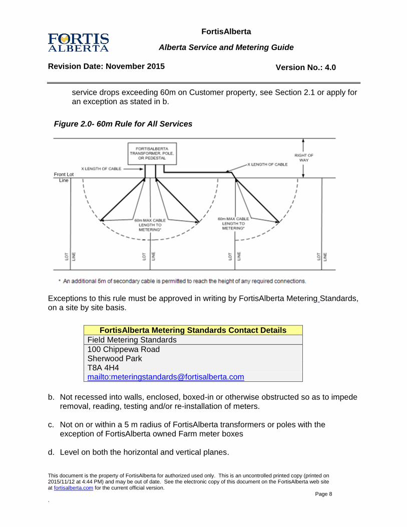
Metering Location – The meter must be:
a. Located not more than 60 m from the front property line or FortisAlberta service transformer located on customer property. For all residential lots or acreages with
FortisAlberta
Alberta Service and Metering Guide
Revision Date: November 2015 Version No.: 4.0
This document is the property of FortisAlberta for authorized used only. This is an uncontrolled printed copy (printed on 2015/11/12 at 4:44 PM) and may be out of date. See the electronic copy of this document on the FortisAlberta web site at fortisalberta.com for the current official version.
Page 8 .
service drops exceeding 60m on Customer property, see Section 2.1 or apply for an exception as stated in b.
Figure 2.0- 60m Rule for All Services
Front Lot
Line
Exceptions to this rule must be approved in writing by FortisAlberta Metering Standards, on a site by site basis.
b. Not recessed into walls, enclosed, boxed-in or otherwise obstructed so as to impede
removal, reading, testing and/or re-installation of meters. c. Not on or within a 5 m radius of FortisAlberta transformers or poles with the
exception of FortisAlberta owned Farm meter boxes d. Level on both the horizontal and vertical planes.
FortisAlberta Metering Standards Contact Details
Field Metering Standards
100 Chippewa Road Sherwood Park T8A 4H4 mailto:[email protected]
FortisAlberta
Alberta Service and Metering Guide
Revision Date: November 2015 Version No.: 4.0
This document is the property of FortisAlberta for authorized used only. This is an uncontrolled printed copy (printed on 2015/11/12 at 4:44 PM) and may be out of date. See the electronic copy of this document on the FortisAlberta web site at fortisalberta.com for the current official version.
Page 9 .
e. Free of severe or continual vibration. f. In a clean and readily accessible area. Not in areas that are hazardous to anyone
installing or working on the metering equipment or reading the meter. Hazardous locations are defined as any area involving moving machinery, dust, vibration, fumes, water/moisture and H2S.
g. Not located in biologically hazardous areas such as poultry/livestock facilities.
FortisAlberta metering shall be located far enough away from production areas so as to eliminate the danger to FortisAlberta staff (that shall visit the site) from contacting any disease or virus.
h. Upstream from any customer dry type step down transformers without FortisAlberta written permission.
i. Not be installed in carports, breezeways or under sundecks or balconies
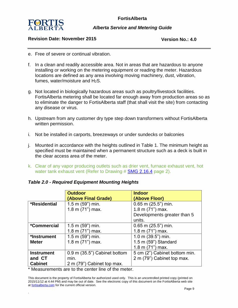
j. Mounted in accordance with the heights outlined in Table 1. The minimum height as specified must be maintained when a permanent structure such as a deck is built in the clear access area of the meter.
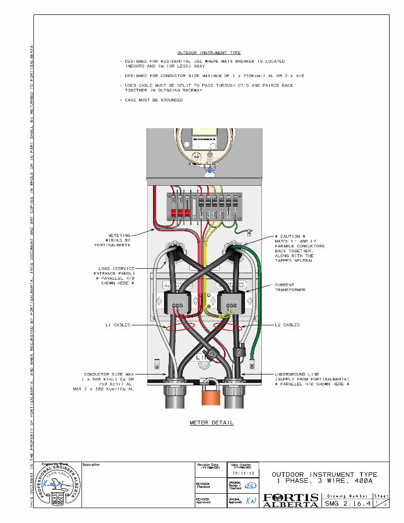
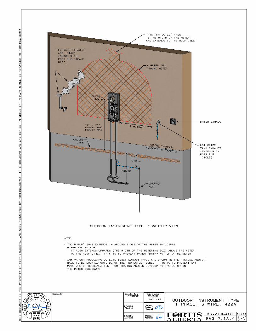
k. Clear of any vapor producing outlets such as drier vent, furnace exhaust vent, hot water tank exhaust vent (Refer to Drawing # SMG 2.16.4 page 2).
Table 2.0 - Required Equipment Mounting Heights
Outdoor (Above Final Grade)
Indoor (Above Floor)
*Residential 1.5 m (59”) min. 1.8 m (71”) max.
0.65 m (25.5”) min. 1.8 m (71”) max. Developments greater than 5 units.
*Commercial 1.5 m (59”) min. 1.8 m (71”) max.
0.65 m (25.5”) min. 1.8 m (71”) max.
*Instrument Meter
1.5 m (59”) min. 1.8 m (71”) max.
1.0 m (39.5”) min. 1.5 m (59”) Standard 1.8 m (71”) max.
Instrument and CT Cabinet
0.9 m (35.5”) Cabinet bottom min. 2 m (79”) Cabinet top max.
5 cm (2”) Cabinet bottom min. 2 m (79”) Cabinet top max.
* Measurements are to the center line of the meter.
FortisAlberta
Alberta Service and Metering Guide
Revision Date: November 2015 Version No.: 4.0
This document is the property of FortisAlberta for authorized used only. This is an uncontrolled printed copy (printed on 2015/11/12 at 4:44 PM) and may be out of date. See the electronic copy of this document on the FortisAlberta web site at fortisalberta.com for the current official version.
Page 10 .
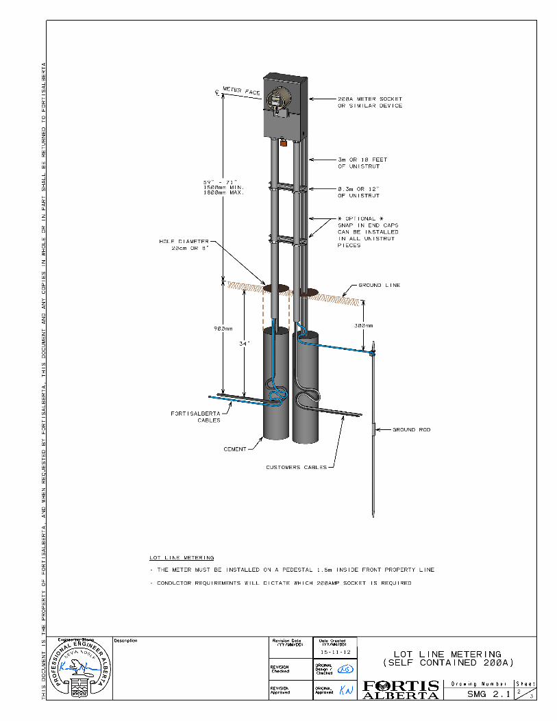
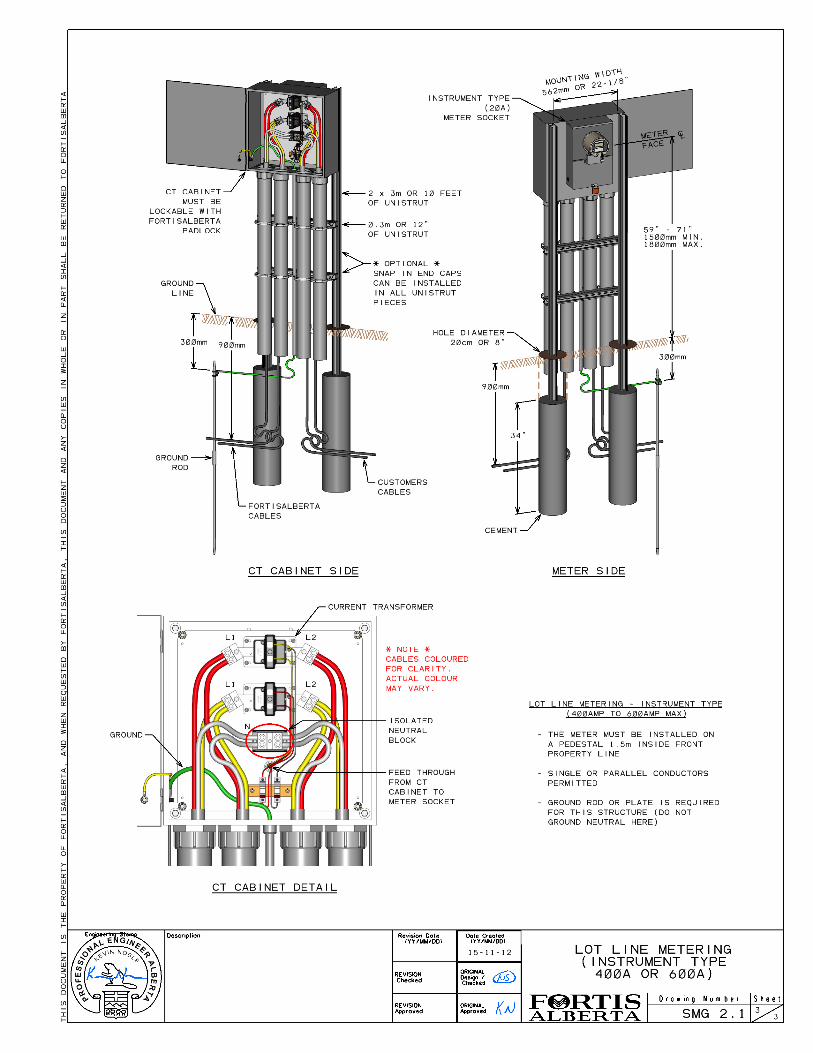
2.1 Lot Line Metering
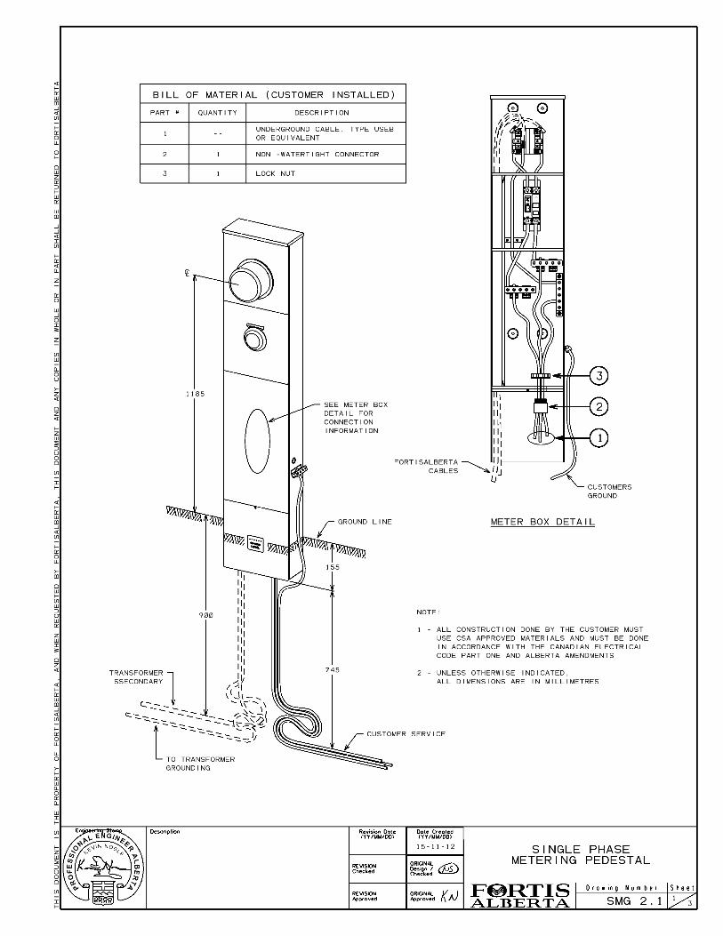
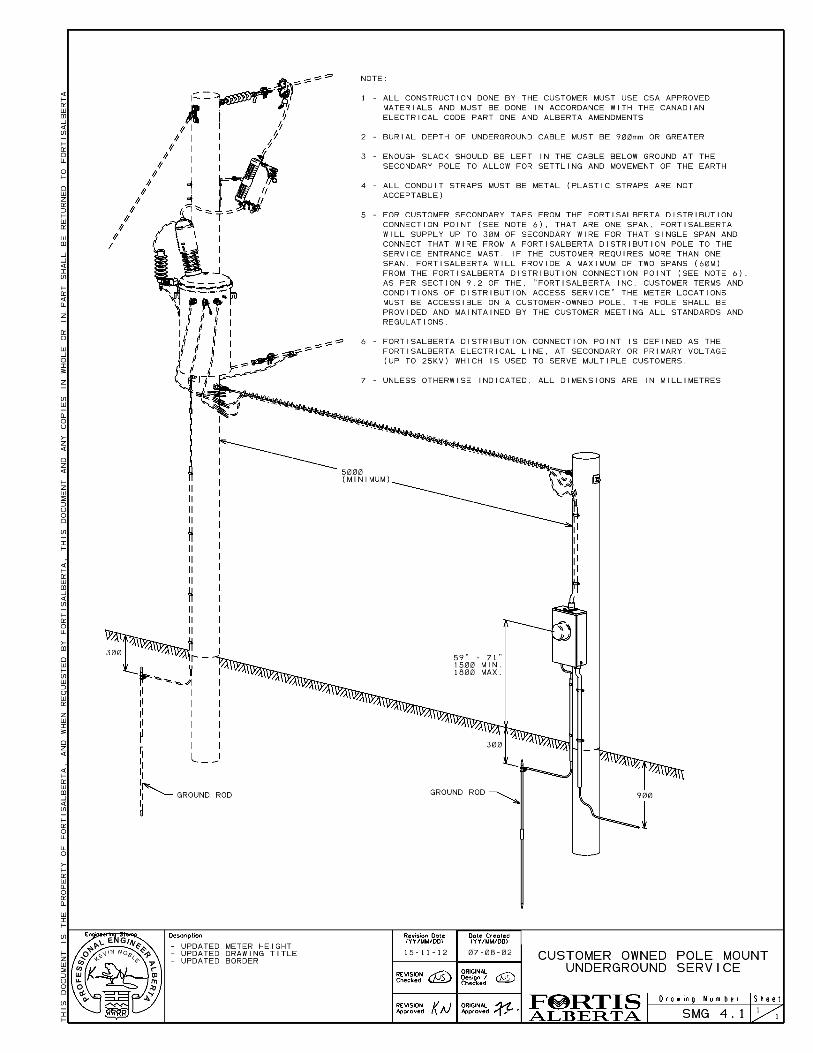
For all residential lots or acreages with service drops exceeding 60m on Customer property, meter must be located on a pedestal or suitable metering structure 1.5m inside the front property line. This “Lot Line Metering” removes any restrictions on secondary conductor length, but not voltage drop requirements of (Section 2.12). A breaker panel is not required at the Lot Line Metering location unless there is a decrease in conductor size or branch circuit(s) are connected at the meter pedestal. (see Drawing # SMG 2.1)
2.2 Safety Codes Act and Associated Regulations
FortisAlberta shall not connect or allow connection of a Customer’s service to the electrical utility system unless all the following criteria are met: a. The attachment point for conductor's used on overhead systems to supply the
Customer's service is located so that the conductors maintain required clearances as defined in CEC rule 6-112
b. The metering equipment and location is acceptable.
c. The Customer's service panel covers are in place. Note: All covers for an electrical service entrance box are to be in place, so there are no exposed energized conductors.
d. The Customer's service is grounded. Note: Refer to the Canadian Electrical Code (CEC) - Section 10 for the requirements for grounding of a service.
e. The utility has received a copy of a valid permit or authorization (see Appendix A.1, Electrical Service Connection Authorization) issued by the inspection authority having jurisdiction. Note: A valid permit only requires having the information that includes the Safety Codes Officer's name, the safety codes officer's designation number, and the agency to which he is employed with, including the applicable intended purpose, (i.e. "service connection"). Note: Federal Jurisdiction, (i.e. National Parks, First Nations, Military Bases), are not required to have a permit unless determined by the authority of that jurisdiction.
2.3 Access to Metering Equipment
FortisAlberta staff shall have reasonable access to all metering equipment for the purpose of changing, testing and reading. Where FortisAlberta is not given ready access to the metering equipment due to locked doors, FortisAlberta may request a key.
FortisAlberta
Alberta Service and Metering Guide
Revision Date: November 2015 Version No.: 4.0
This document is the property of FortisAlberta for authorized used only. This is an uncontrolled printed copy (printed on 2015/11/12 at 4:44 PM) and may be out of date. See the electronic copy of this document on the FortisAlberta web site at fortisalberta.com for the current official version.
Page 11 .
A lock-box may be installed by FortisAlberta for the purpose of keeping the key on site. FortisAlberta is absolved from all liability if the lock box is damaged or stolen.
2.4 CSA Approved Device and Meter Socket Requirements
Meter sockets and any additions (e.g. isolated neutral blocks, additional lugs, etc.) must be CSA approved. Any additions to the meter socket shall be supplied by the manufacturer of the meter socket.
2.5 Service Entrance Equipment Requirements
All service entrance equipment shall comply with the following: Conductors:
All service entrances shall be designed and constructed such that metered and un-metered conductors are not run in the same conduit or raceway. Equipment:
All service entrance equipment requires hinged doors over all bare electrical parts. Hinged doors shall open either left or right to not less than 90 degrees for outer and inner doors. The only exception to the direction of opening is for horizontal mounted splitter boxes for which the doors must open downward. All hinged doors that are ahead of the metering point require sealing screws. Barriers are required between all metered and un-metered conductors and between sections reserved for Customer use and those for FortisAlberta’s use.
2.6 Customer owned poles
Customer owned secondary poles shall meet the following requirements: a. Poles shall be a maximum 60m from the front property line or transformer pole
located on customer property.
b. Pole setting depth must be a minimum 10% of the height of the pole plus 0.6 m. FortisAlberta shall supply and install a maximum of two spans of overhead secondary wire and up to one intermediate pole to the customer-owned pole. Each span of overhead secondary wire is limited to 30 m.
2.7 Electrical Equipment Room Requirements
All electrical rooms in which FortisAlberta metering is installed shall be on ground level with outdoor access and shall comply with the following: a. Working Space - A minimum of 1 m working space by 2.2 m high is required in front
of all electrical equipment and to the sides and back where access is required
FortisAlberta
Alberta Service and Metering Guide
Revision Date: November 2015 Version No.: 4.0
This document is the property of FortisAlberta for authorized used only. This is an uncontrolled printed copy (printed on 2015/11/12 at 4:44 PM) and may be out of date. See the electronic copy of this document on the FortisAlberta web site at fortisalberta.com for the current official version.
Page 12 .
(additional requirements are listed in CEC Rule 2-308 and 2-312). Electrical rooms are not to be located in a bathroom or stairway.
b. Entrance and Exit - A minimum passageway of 1 m wide by 2.2 m high shall be maintained as an entrance or exit from all electrical areas. (additional requirements are listed in CEC Rule 2-310)
c. Proximity to Other Equipment - It is not permissible to mount water, sewer, gas or other pipes or equipment foreign to the electrical installation directly above electrical equipment or to encroach on minimum working space around electrical equipment.
d. Hazardous Locations - Electrical equipment cannot be located in areas that are hazardous to anyone working on electrical equipment or to the metering equipment itself. This would include moving machinery, dust, vibration, fumes, water, humidity and H2S. This is also extended to areas where FortisAlberta employees, contractors and vehicles may pose a hazard by transporting viruses or contaminates.
e. Illumination and Ventilation - All electrical rooms or areas shall have adequate illumination and ventilation to carry out all work safely. (as per CEC 2-316 & 2-320)
2.8 Customer Instrumentation and Protection
Customer instrumentation including metering circuits, transfer relays, fire alarms, and step-down transformers shall be connected on the load side of the FortisAlberta meter. These circuits cannot be connected into FortisAlberta metering circuits and all equipment shall be mounted independent of the cabinets reserved for FortisAlberta use. Electronics built into the main breaker, lightning arrestors and passive type surge suppressors are permitted to be located in the main breaker section of the Customer’s switchgear and connected ahead of the FortisAlberta meter.
2.9 Disconnects and Reconnects
a) All disconnects and reconnects shall have prior approval of FortisAlberta and in the absence of an electrical permit, the reconnection may be completed after the “Reconnection Authorization Form” has been signed as required. Electricians must print the form and complete three copies. One each for the Customer, the electrician, and FortisAlberta. The signed copy left for FortisAlberta must be left in the meter socket or in a location agreeable to FortisAlberta prior to connection.
b) The disconnection and reconnection of an existing electrical service by a qualified
electrician is limited to services not greater than 200 amps and 300 volts. The disconnection requires prior approval from FortisAlberta and must not be done at the
FortisAlberta
Alberta Service and Metering Guide
Revision Date: November 2015 Version No.: 4.0
This document is the property of FortisAlberta for authorized used only. This is an uncontrolled printed copy (printed on 2015/11/12 at 4:44 PM) and may be out of date. See the electronic copy of this document on the FortisAlberta web site at fortisalberta.com for the current official version.
Page 13 .
meter. When the disconnection is completed by cutting the hot wires at the weather head, the reconnection must be completed by FortisAlberta.
c) All other disconnects and reconnects shall be completed by FortisAlberta.
2.10 Modifications to Existing Services
Customers planning the following modification and/or additions to their electrical system must comply with present day requirements.
Increase in load
Increase in service conductor size
Installation of back-up power supplies
Installation of a transfer switch To ensure accuracy of metering installations, only FortisAlberta staff who are trained under federal regulations S-A-01 (Criteria for the Accreditation of Organizations to Perform Inspections Pursuant to the Electricity and Gas Inspection Act and the Weights and Measures Act) are authorized to install, remove or handle meters. All meter recertification costs and/or damages associated with removal, installation or handling of meters by unauthorized persons will be the responsibility of the person(s) responsible.
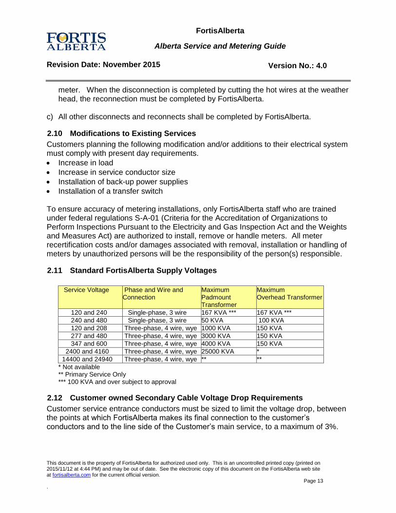
2.11 Standard FortisAlberta Supply Voltages
Service Voltage Phase and Wire and
Connection Maximum Padmount Transformer
Maximum Overhead Transformer
120 and 240 Single-phase, 3 wire 167 KVA *** 167 KVA ***
240 and 480 Single-phase, 3 wire 50 KVA 100 KVA
120 and 208 Three-phase, 4 wire, wye 1000 KVA 150 KVA
277 and 480 Three-phase, 4 wire, wye 3000 KVA 150 KVA
347 and 600 Three-phase, 4 wire, wye 4000 KVA 150 KVA
2400 and 4160 Three-phase, 4 wire, wye 25000 KVA *
14400 and 24940 Three-phase, 4 wire, wye ** **
* Not available ** Primary Service Only *** 100 KVA and over subject to approval
2.12 Customer owned Secondary Cable Voltage Drop Requirements
Customer service entrance conductors must be sized to limit the voltage drop, between the points at which FortisAlberta makes its final connection to the customer’s conductors and to the line side of the Customer’s main service, to a maximum of 3%.
FortisAlberta
Alberta Service and Metering Guide
Revision Date: November 2015 Version No.: 4.0
This document is the property of FortisAlberta for authorized used only. This is an uncontrolled printed copy (printed on 2015/11/12 at 4:44 PM) and may be out of date. See the electronic copy of this document on the FortisAlberta web site at fortisalberta.com for the current official version.
Page 14 .
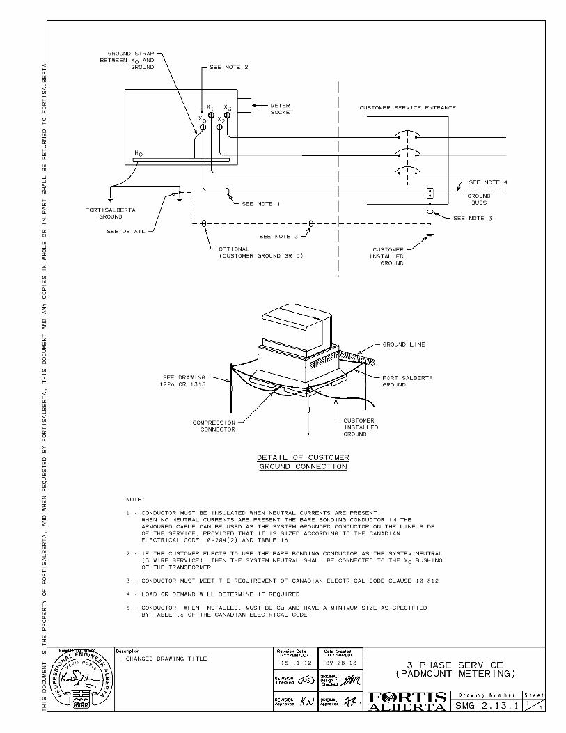
2.13 Three-Phase Services
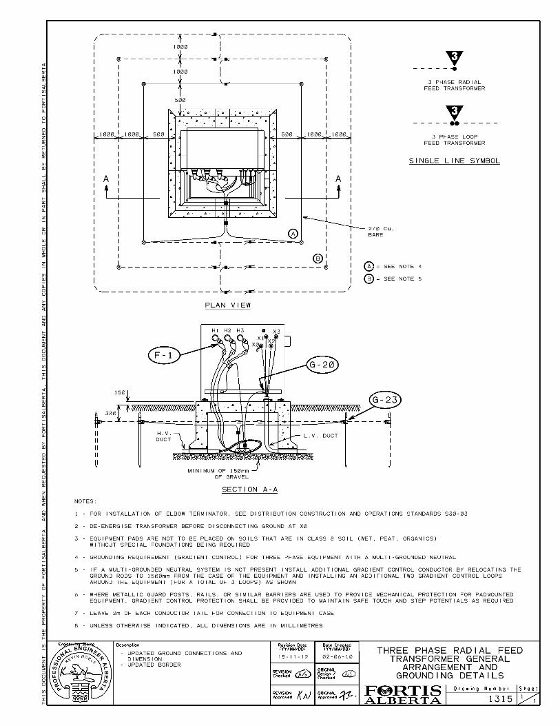
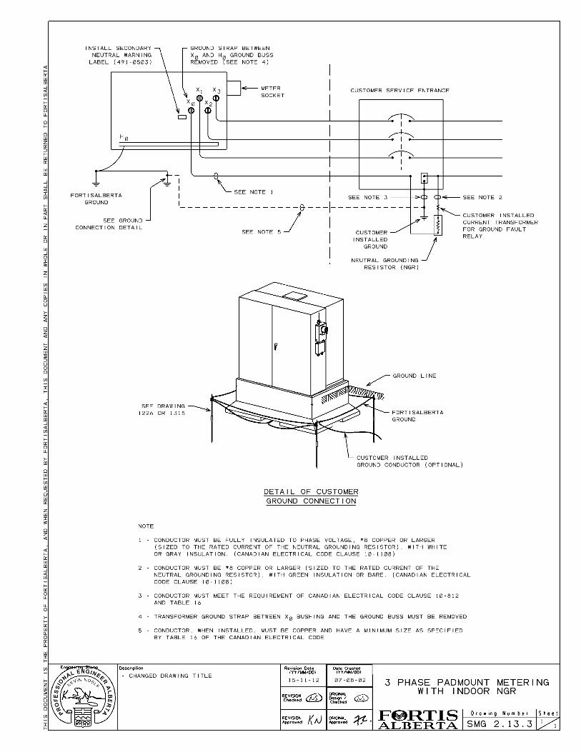
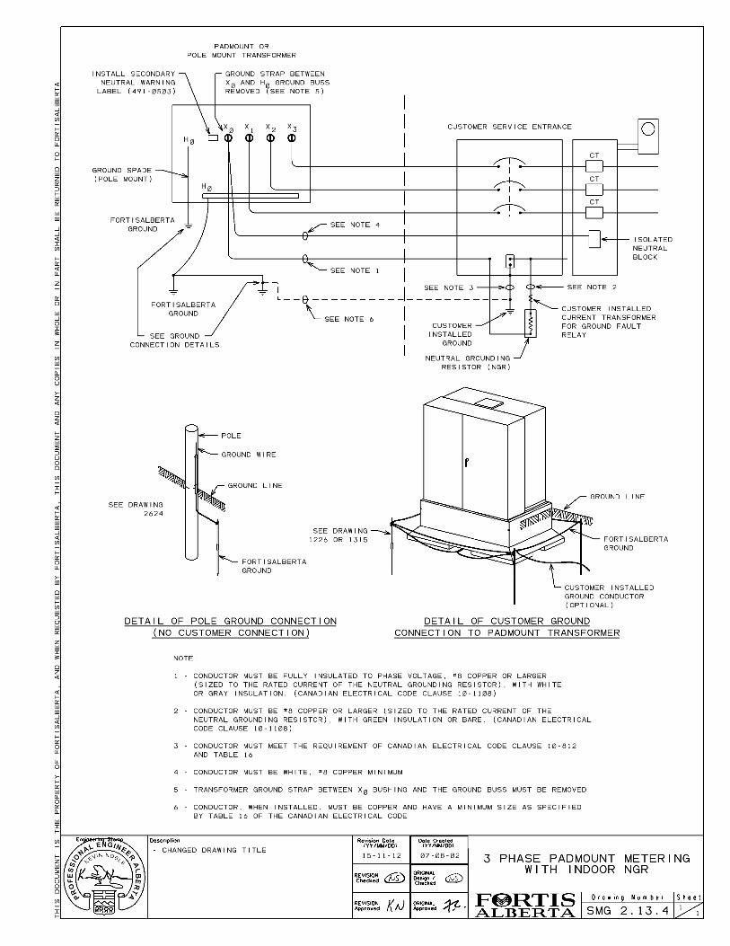
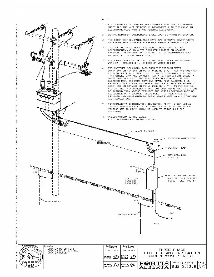
All three phase services shall be four wire, grounded wye, with the grounded conductor run into the main breaker and bonded to the ground electrode and must be connected to the supply transformer X0 bushing (not ground bus or case ground). Any variation from this, unless otherwise arranged and approved in writing by FortisAlberta shall result in the service not being energized. With the grounded conductor grounded at the main service disconnect, all points beyond (downstream) this, the neutral shall be isolated from ground. The use of an isolated neutral block is necessary when the metering point (self-contained or instrument type) is on the load side of the main service disconnect. Refer to Drawing # SMG 2.13.1 through SMG 2.13.4 for three-phase underground service details. Refer to Drawing SMG 2.13.5 for three-phase overhead oilfield and irrigation service details.
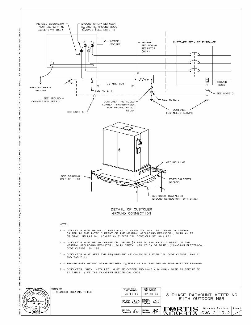
2.13.1 Neutral Grounding Resistors (NGR)
The Customer must advise FortisAlberta of the intent to install an NGR. NGRs are not permitted on services with self-contained meters. The Customer shall provide FortisAlberta with the rating and location of the grounding resistor.
2.14 Services That Do Not Require Metering
FortisAlberta requires all services be metered, with an exception for some applications such as emergency warning sirens.
2.15 Self-Contained Metering
The maximum limits for self-contained metering are:
200 amps per phase and/or;
600 volts phase to phase and/or;
130 HP continuous duty motor load at 480 volts phase to phase (CEC Rule 28-106 and 28-704)
Self-contained metering is to be used on all 200 amp services or less, with an exception for services supplied by a dedicated padmount transformer, were the Customer has the option to pay for metering attached to the transformer. Padmount metering will be quoted as Optional Facilities. If service requirements are greater than the current, voltage or load limits given above, refer to the Section 2.16 Instrument Metering. Any service found exceeding the above requirements shall be re-wired to instrument metering at the Customer’s expense or the service will be disconnected.
FortisAlberta
Alberta Service and Metering Guide
Revision Date: November 2015 Version No.: 4.0
This document is the property of FortisAlberta for authorized used only. This is an uncontrolled printed copy (printed on 2015/11/12 at 4:44 PM) and may be out of date. See the electronic copy of this document on the FortisAlberta web site at fortisalberta.com for the current official version.
Page 15 .
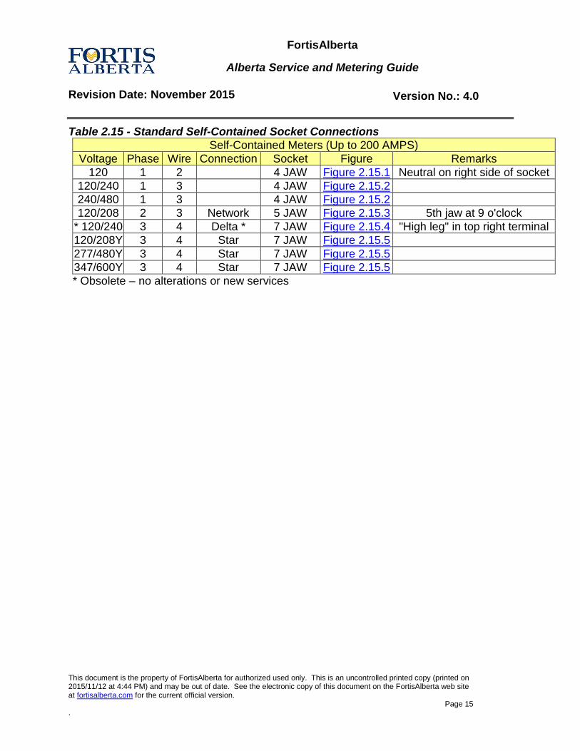
Table 2.15 - Standard Self-Contained Socket Connections
Self-Contained Meters (Up to 200 AMPS)
Voltage Phase Wire Connection Socket Figure Remarks
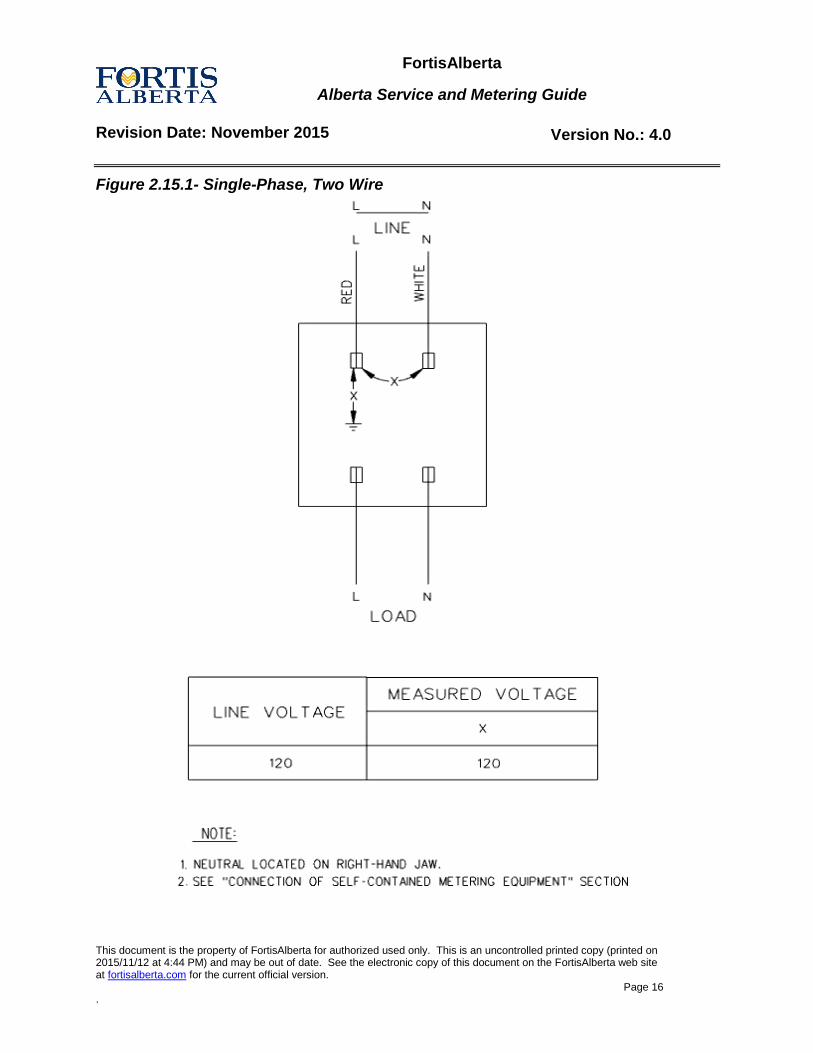
120 1 2 4 JAW Figure 2.15.1 Neutral on right side of socket
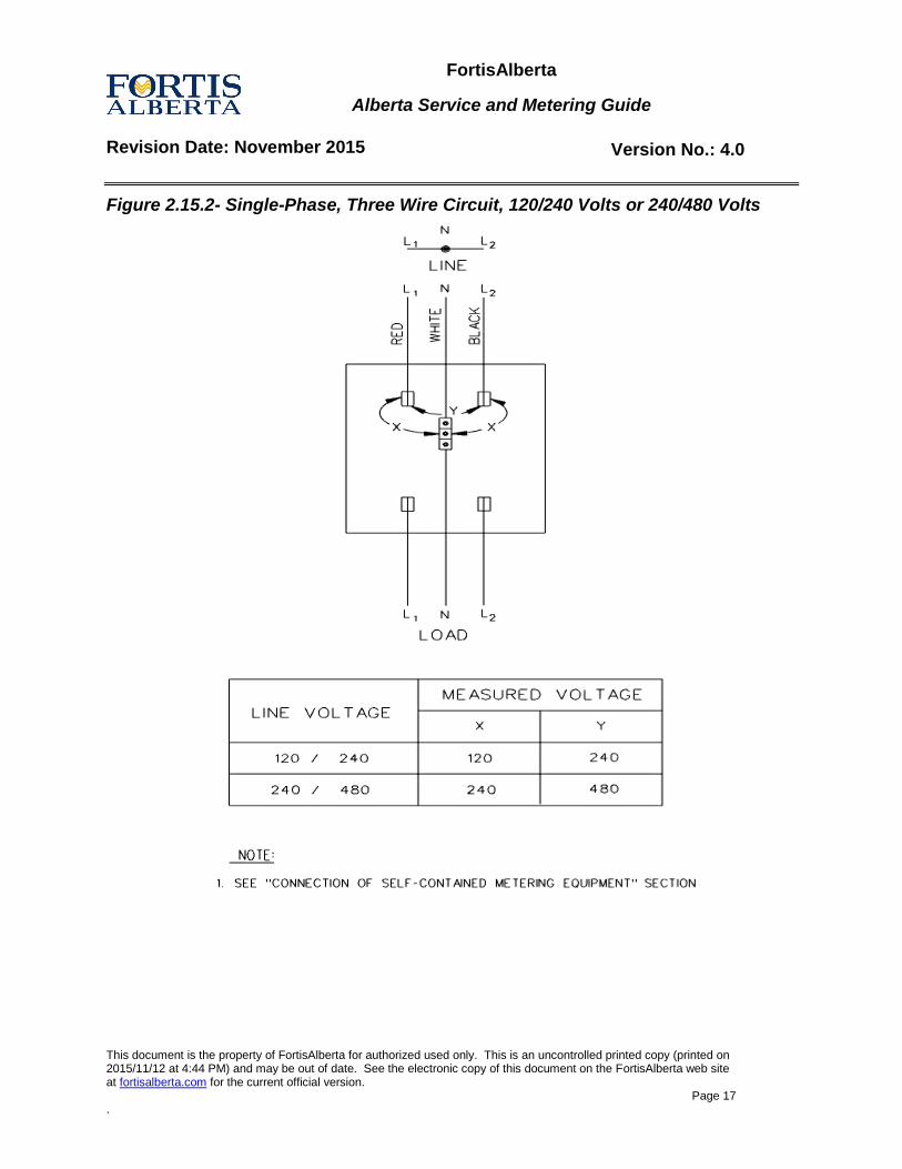
120/240 1 3 4 JAW Figure 2.15.2
240/480 1 3 4 JAW Figure 2.15.2
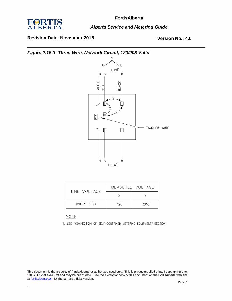
120/208 2 3 Network 5 JAW Figure 2.15.3 5th jaw at 9 o'clock
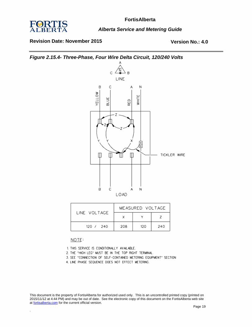
* 120/240 3 4 Delta * 7 JAW Figure 2.15.4 "High leg" in top right terminal
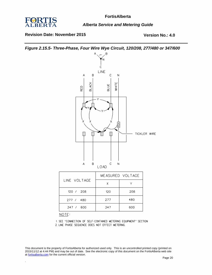
120/208Y 3 4 Star 7 JAW Figure 2.15.5
277/480Y 3 4 Star 7 JAW Figure 2.15.5
347/600Y 3 4 Star 7 JAW Figure 2.15.5
* Obsolete – no alterations or new services
FortisAlberta
Alberta Service and Metering Guide
Revision Date: November 2015 Version No.: 4.0
This document is the property of FortisAlberta for authorized used only. This is an uncontrolled printed copy (printed on 2015/11/12 at 4:44 PM) and may be out of date. See the electronic copy of this document on the FortisAlberta web site at fortisalberta.com for the current official version.
Page 16 .
Figure 2.15.1- Single-Phase, Two Wire
FortisAlberta
Alberta Service and Metering Guide
Revision Date: November 2015 Version No.: 4.0
This document is the property of FortisAlberta for authorized used only. This is an uncontrolled printed copy (printed on 2015/11/12 at 4:44 PM) and may be out of date. See the electronic copy of this document on the FortisAlberta web site at fortisalberta.com for the current official version.
Page 17 .
Figure 2.15.2- Single-Phase, Three Wire Circuit, 120/240 Volts or 240/480 Volts
FortisAlberta
Alberta Service and Metering Guide
Revision Date: November 2015 Version No.: 4.0
This document is the property of FortisAlberta for authorized used only. This is an uncontrolled printed copy (printed on 2015/11/12 at 4:44 PM) and may be out of date. See the electronic copy of this document on the FortisAlberta web site at fortisalberta.com for the current official version.
Page 18 .
Figure 2.15.3- Three-Wire, Network Circuit, 120/208 Volts
FortisAlberta
Alberta Service and Metering Guide
Revision Date: November 2015 Version No.: 4.0
This document is the property of FortisAlberta for authorized used only. This is an uncontrolled printed copy (printed on 2015/11/12 at 4:44 PM) and may be out of date. See the electronic copy of this document on the FortisAlberta web site at fortisalberta.com for the current official version.
Page 19 .
Figure 2.15.4- Three-Phase, Four Wire Delta Circuit, 120/240 Volts
FortisAlberta
Alberta Service and Metering Guide
Revision Date: November 2015 Version No.: 4.0
This document is the property of FortisAlberta for authorized used only. This is an uncontrolled printed copy (printed on 2015/11/12 at 4:44 PM) and may be out of date. See the electronic copy of this document on the FortisAlberta web site at fortisalberta.com for the current official version.
Page 20 .
Figure 2.15.5- Three-Phase, Four Wire Wye Circuit, 120/208, 277/480 or 347/600
FortisAlberta
Alberta Service and Metering Guide
Revision Date: November 2015 Version No.: 4.0
This document is the property of FortisAlberta for authorized used only. This is an uncontrolled printed copy (printed on 2015/11/12 at 4:44 PM) and may be out of date. See the electronic copy of this document on the FortisAlberta web site at fortisalberta.com for the current official version.
Page 21 .
2.15.1 Supply of Self-Contained Metering Equipment
The Customer is required to supply a meter socket complete with a screw type sealing ring for FortisAlberta use. Sockets with bypass switches will not be accepted.
2.15.2 Connection of Self-Contained Metering Equipment
The Customer is responsible to make all connections within the meter socket. The main service neutral shall be connected to the neutral socket lug within the meter socket. Junction boxes are not permitted ahead of the FortisAlberta meter. For single phase 240/480V services the meter socket shall be located after the main breaker and have the neutral isolated from its case. The only exception to this is where the meter socket is located on the load side of the service disconnect and the neutral is not required for the Customer's equipment. In this case a tap of minimum size #6 AWG conductor color coded white shall be run from the isolated neutral block in the socket, back to the neutral bonding point in the main service disconnect. All neutral connections after the main service disconnect shall be isolated from ground (CEC Rule 10-204-1c). In the case of meter sockets located after the main disconnect an isolated neutral block shall be used. NGR’s are not permitted on services with a self-contained meter.
2.16 Instrument Metering
Instrument transformer type metering is required on all services:
Exceeding 200 amps per phase and/or
Exceeding 600 volts phase-to-phase and/or
Exceeding 130 HP continuous duty motor load at 480 volts phase to phase. (CEC Rule 28-106 and 28-704)
For all services that require instrument metering and are supplied from a dedicated padmount transformer, padmount metering will be installed by FortisAlberta. For services supplied from an overhead transformer or a shared padmount transformer, instrument metering shall meet the requirements outlined in this guide unless special permission is obtained from FortisAlberta Metering Standards (refer to Section 3.0).
2.16.1 Instrument metering equipment location and mounting requirements
Both the instrument meter socket and instrument transformer enclosure must be located:
Both indoors or both outdoors
In the same room (indoors).
FortisAlberta
Alberta Service and Metering Guide
Revision Date: November 2015 Version No.: 4.0
This document is the property of FortisAlberta for authorized used only. This is an uncontrolled printed copy (printed on 2015/11/12 at 4:44 PM) and may be out of date. See the electronic copy of this document on the FortisAlberta web site at fortisalberta.com for the current official version.
Page 22 .
Within a maximum length of 7 m of 35mm (1 ¼”) conduit between the meter socket and the instrument transformer enclosure.
The use of “LB” style fittings are permitted only if there is no other means to route the conduit.
2.16.2 Connections of instrument metering equipment
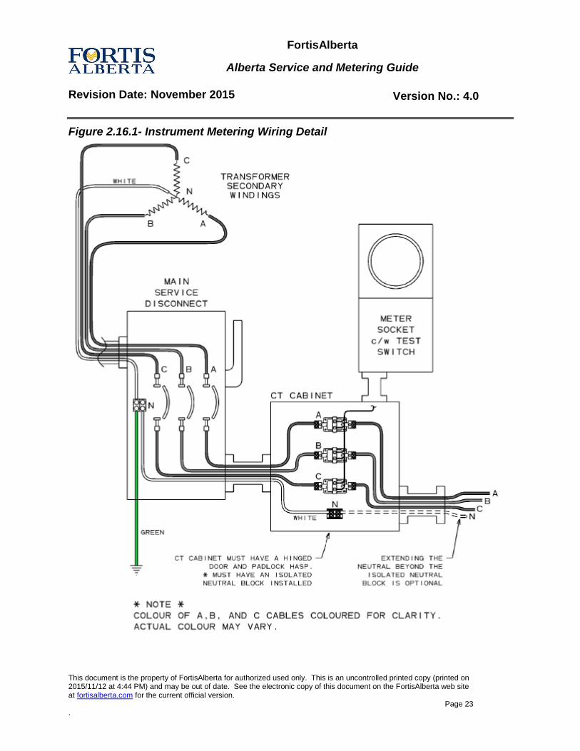
The Customer is responsible to make all connections to the current transformer primaries. These connections shall be properly secured and conductors shall be shaped or formed and supported so that no tension is applied to the current transformers. FortisAlberta supplies a three phase, four-wire service. The neutral bus bar shall be run into the instrument enclosure from the main service disconnect and a hole tapped for a 10/32” screw. When insulated cable is used instead of a bus bar, an approved isolated neutral block shall be provided with the neutral conductor within the instrument transformer enclosure to facilitate the connection of the potential wire for the meter. If the neutral consists of two or more conductors, only one of the conductors need be tapped for the metering neutral connection. Unless an NGR is installed, all three-phase services will be supplied as three phase, four wire grounded-wye. The resulting requirement is that the ground conductor required by CEC Rule 10-204 shall be run from the X0 Bushing of the supply transformer, to the bonding terminal block in the main service disconnect and also to the switchgear case ground. An insulated conductor of minimum size of #6 AWG is to be run from the bonding terminal block to an isolated neutral block in the instrument transformer enclosure (refer to Figure 2.16.1). The conductor to the instrument transformer enclosure shall be coded white to indicate the neutral reference for metering. FortisAlberta shall make all connections to potential transformers; current transformer secondary’s, fuse blocks and the meter socket (refer to Figure 2.16.2).
Instrument meter socket and enclosure grounding
Each meter socket shall be grounded to the system ground. Conduit requirements:
A metal conduit, 35mm (1 ¼”) diameter and a maximum length of 7 m is required between the instrument transformer enclosure and meter socket. This conduit shall be terminated with lock nuts and bushings except where thread hubs are supplied. If L.B.'s or similar conduit fittings shall be used, they shall be seal-able and clearly visible.
The conduit is for exclusive use of FortisAlberta. When it is necessary to route metering secondary wires through compartments other than those reserved for FortisAlberta's use, a metal conduit shall be passed through each compartment.
FortisAlberta
Alberta Service and Metering Guide
Revision Date: November 2015 Version No.: 4.0
This document is the property of FortisAlberta for authorized used only. This is an uncontrolled printed copy (printed on 2015/11/12 at 4:44 PM) and may be out of date. See the electronic copy of this document on the FortisAlberta web site at fortisalberta.com for the current official version.
Page 23 .
Figure 2.16.1- Instrument Metering Wiring Detail
FortisAlberta
Alberta Service and Metering Guide
Revision Date: November 2015 Version No.: 4.0
This document is the property of FortisAlberta for authorized used only. This is an uncontrolled printed copy (printed on 2015/11/12 at 4:44 PM) and may be out of date. See the electronic copy of this document on the FortisAlberta web site at fortisalberta.com for the current official version.
Page 24 .
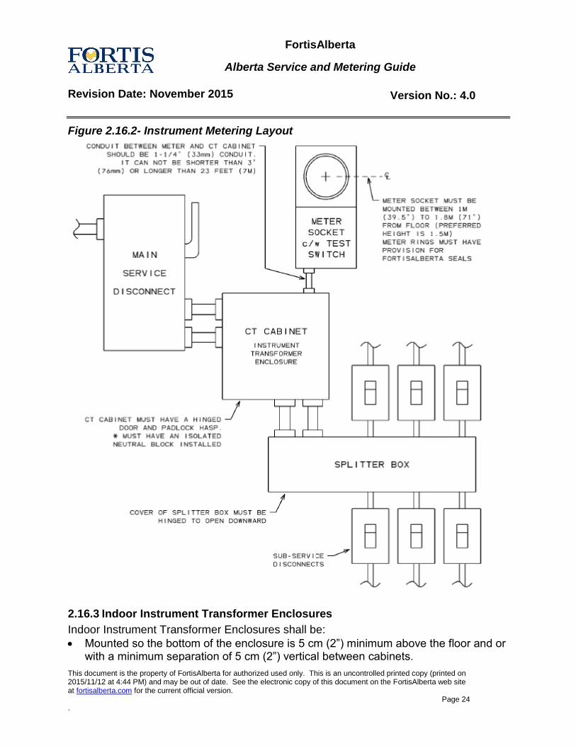
Figure 2.16.2- Instrument Metering Layout
2.16.3 Indoor Instrument Transformer Enclosures
Indoor Instrument Transformer Enclosures shall be:
Mounted so the bottom of the enclosure is 5 cm (2”) minimum above the floor and or with a minimum separation of 5 cm (2”) vertical between cabinets.
FortisAlberta
Alberta Service and Metering Guide
Revision Date: November 2015 Version No.: 4.0
This document is the property of FortisAlberta for authorized used only. This is an uncontrolled printed copy (printed on 2015/11/12 at 4:44 PM) and may be out of date. See the electronic copy of this document on the FortisAlberta web site at fortisalberta.com for the current official version.
Page 25 .
Mounted so the top of the enclosure is a maximum of 2 m (78”) above the floor For instrument transformer cabinet sizes, refer to Section 2.16.5.
2.16.4 Outdoor Instrument Transformer Enclosures
Outdoor Instrument Transformer Enclosures shall be (Refer to Drawing # SMG 2.16.4):
Mounted so the bottom of the enclosure is 0.9 m (36”) minimum above the final grade.
Mounted so the top of the enclosure is a maximum of 2 m (78”) above the final grade.
A separate instrument transformer enclosure is required for each instrument transformer service.
For instrument transformer cabinet sizes, refer to Section 2.16.5.
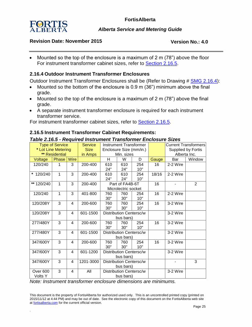
2.16.5 Instrument Transformer Cabinet Requirements:
Table 2.16.5 - Required Instrument Transformer Enclosure Sizes Type of Service
* Lot Line Metering ** Residential
Service Size
in Amps
Instrument Transformer Enclosure Size (mm/in.)
Min. sizes
Current Transformers Supplied by Fortis
Alberta Inc.
Voltage Phase Wire H W D Gauge Bar Window
120/240 1 3 200-400 610 24"
610 24"
254 10"
16 2-2 Wire
* 120/240 1 3 200-400 610 24"
610 24"
254 10"
18/16 2-2 Wire
** 120/240 1 3 200-400 Part of FA4B-6T Microlectric socket
16 - 2
120/240 1 3 401-800 760 30"
760 30"
254 10"
16 2-2 Wire
120/208Y 3 4 200-600 760 30"
760 30"
254 10"
16 3-2 Wire
120/208Y 3 4 601-1500 Distribution Centersc/w bus bars)
3-2 Wire
277/480Y 3 4 200-600 760 30"
760 30"
254 10"
16 3-2 Wire
277/480Y 3 4 601-1500 Distribution Centersc/w bus bars)
3-2 Wire
347/600Y 3 4 200-600 760 30"
760 30"
254 10"
16 3-2 Wire
347/600Y 3 4 601-1200
Distribution Centersc/w bus bars)
3-2 Wire
347/600Y 3 4 1201-3000 Distribution Centersc/w bus bars)
- 3
Over 600 Volts Y
3 4 All Distribution Centersc/w bus bars)
3-2 Wire
Note: Instrument transformer enclosure dimensions are minimums.
FortisAlberta
Alberta Service and Metering Guide
Revision Date: November 2015 Version No.: 4.0
This document is the property of FortisAlberta for authorized used only. This is an uncontrolled printed copy (printed on 2015/11/12 at 4:44 PM) and may be out of date. See the electronic copy of this document on the FortisAlberta web site at fortisalberta.com for the current official version.
Page 26 .
Instrument transformer enclosure doors
The instrument transformer enclosure shall be equipped with vertically hinged door(s), which are non-removable in the closed position and equipped with stops to prevent the doors from accidentally dropping off the hinges in the open position.
These door(s) shall be equipped with a latch and have provisions for securing the door with a FortisAlberta padlock.
Cover plates
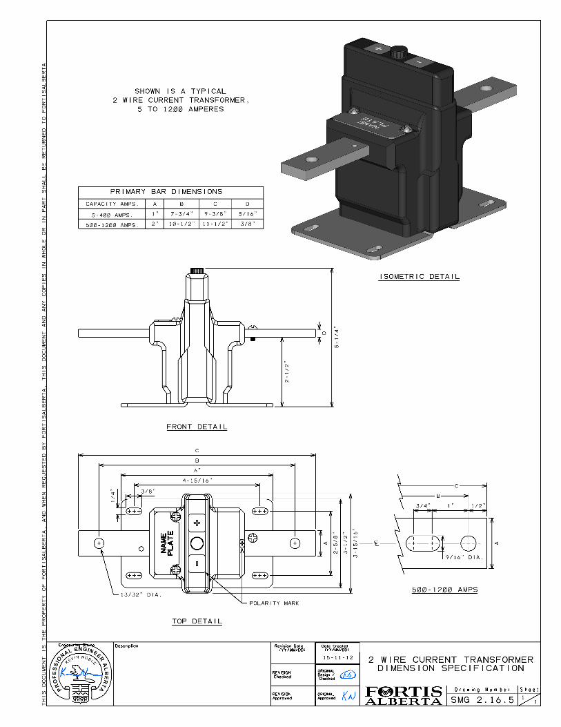
Cover plates are not acceptable on instrument transformers. Current Transformer
Refer to Drawing # SMG 2.16.5 for two-wire current transformer dimensions.
3.0 Non-Standard Services
For services were requirements of this guide cannot be met, the Customer must: a. Submit equipment drawings, specifications and site plans to FortisAlberta Metering
Standards for approval before ordering and installing service entrance equipment or associated equipment.
b. Drawings submitted shall clearly show all equipment related to the meter, including service entrance equipment and meter enclosures. These drawings should show elevations and enclosures sizes. In some cases a hand drawn sketch that clearly shows the layout and dimensions is all that is needed.
c. FortisAlberta Metering Standards will evaluate the submitted documents and issue a ruling on the non-standard service. An approval letter shall be received back before the service can be considered approved.
In case of a dispute, FortisAlberta staff will not honour verbal conversations. Prints and/or a letter approved by Metering Standards is required prior to non-standard services being energized. Any approval is only for the service in question and is not a general approval for future services.
FortisAlberta Metering Standards Contact Details
Field Metering Standards
100 Chippewa Road Sherwood Park T8A 4H4 mailto:[email protected]
FortisAlberta
Alberta Service and Metering Guide
Revision Date: November 2015 Version No.: 4.0
This document is the property of FortisAlberta for authorized used only. This is an uncontrolled printed copy (printed on 2015/11/12 at 4:44 PM) and may be out of date. See the electronic copy of this document on the FortisAlberta web site at fortisalberta.com for the current official version.
Page 27 .
4.0 Residential Services
All single residential services must have the metering located outdoors. Multiple Residential Services shall meet the requirements of Section 4.4. Metering equipment is required to meet the General Requirements outlined in Section 2.0 in addition to the following: a. Meter shall be installed on
i. the outside wall of a house or suitable building, or ii. a separate suitable pedestal or post, as in the case of lot line metering, refer
to Drawing # SMG 2.1, or b. Meter shall be connected on the line side of the service disconnect.
4.1 Overhead Service Supplied by an Overhead Transformer
The Customer shall:
Supply and install the meter socket(s).
Supply and install a metallic service entrance mast complete with weather head, clevis insulator and cable. The service mast or clevis insulator complete with bolt, shall be securely fastened to the building. Note: Screw type insulators (service knobs) will not be accepted on new or upgraded construction.
Supply and install service pole, if required.
For Customer pole metering: o Supply and install metering pole (refer to Drawing # SMG 4.1)
FortisAlberta shall:
Supply and install the meter.
Supply and install up to 60 m of secondary cable with any one span being a maximum of 30 m.
4.2 Underground Service Supplied by an Overhead Transformer
The Customer shall:
Supply and install the meter socket.
Supply and install the service entrance conduit.
Provide all trench excavation on Customer property and lease property and all backfilling of any trench.
FortisAlberta
Alberta Service and Metering Guide
Revision Date: November 2015 Version No.: 4.0
This document is the property of FortisAlberta for authorized used only. This is an uncontrolled printed copy (printed on 2015/11/12 at 4:44 PM) and may be out of date. See the electronic copy of this document on the FortisAlberta web site at fortisalberta.com for the current official version.
Page 28 .
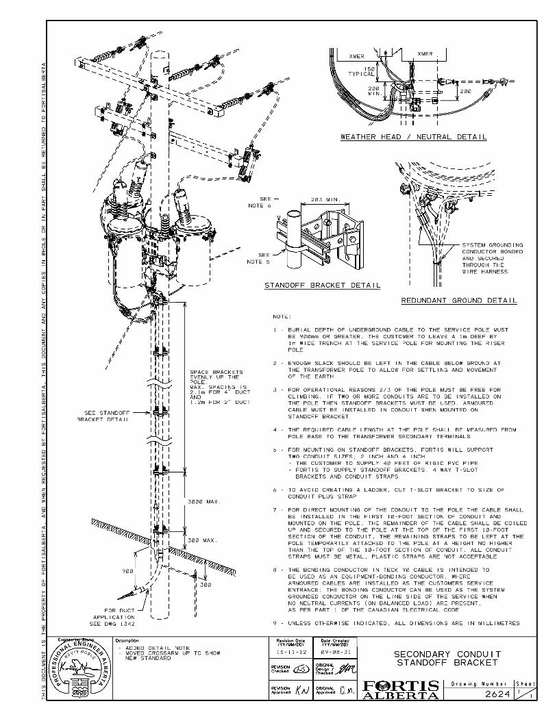
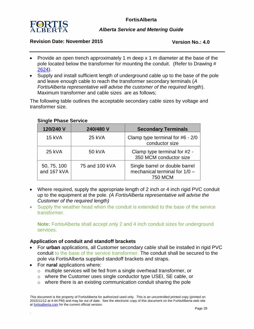
Provide an open trench approximately 1 m deep x 1 m diameter at the base of the pole located below the transformer for mounting the conduit. (Refer to Drawing # 2624).
Supply and install sufficient length of underground cable up to the base of the pole and leave enough cable to reach the transformer secondary terminals (A FortisAlberta representative will advise the customer of the required length). Maximum transformer and cable sizes are as follows;
The following table outlines the acceptable secondary cable sizes by voltage and transformer size.
Single Phase Service
120/240 V 240/480 V Secondary Terminals
15 kVA 25 kVA Clamp type terminal for #6 - 2/0 conductor size
25 kVA 50 kVA Clamp type terminal for #2 - 350 MCM conductor size
50, 75, 100 and 167 kVA
75 and 100 kVA Single barrel or double barrel mechanical terminal for 1/0 –
750 MCM
Where required, supply the appropriate length of 2 inch or 4 inch rigid PVC conduit up to the equipment at the pole. (A FortisAlberta representative will advise the Customer of the required length)
Supply the weather head when the conduit is extended to the base of the service transformer. Note: FortisAlberta shall accept only 2 and 4 inch conduit sizes for underground services.
Application of conduit and standoff brackets
For urban applications, all Customer secondary cable shall be installed in rigid PVC conduit to the base of the service transformer. The conduit shall be secured to the pole via FortisAlberta supplied standoff brackets and straps.
For rural applications where: o multiple services will be fed from a single overhead transformer, or o where the Customer uses single conductor type USEI, SE cable, or o where there is an existing communication conduit sharing the pole
FortisAlberta
Alberta Service and Metering Guide
Revision Date: November 2015 Version No.: 4.0
This document is the property of FortisAlberta for authorized used only. This is an uncontrolled printed copy (printed on 2015/11/12 at 4:44 PM) and may be out of date. See the electronic copy of this document on the FortisAlberta web site at fortisalberta.com for the current official version.
Page 29 .
the cable shall be installed in conduit to the base of the service transformer. The conduit shall be secured to the pole via Fortis supplied standoff brackets and straps.
For rural application where: o type USEB, SE or armored cable is used, and o where there will be only a single service fed from an overhead transformer,
the first 10 feet of cable will require conduit. The conduit shall then be sized appropriately for the installation (this will be the only exception to the 2 and 4 inch guideline). The Customer will pull the cable through the rigid PVC conduit and secure it to the pole via Customer supplied straps. The remaining SE or armored cable shall be coiled and secured to the pole with appropriately sized cable straps (weather head is not required), bagged, and secured to the pole.
If the customer chooses to use multi conductor armored cable then the last 2 m of the cable must be stripped of the cable armor exposing the PVC inner jacket. The PVC jacket shall then be covered with color coded heat shrink tubing. o The conductor intended to be used as the neutral shall be clearly identifiable via
white vinyl tape or heat shrink tubing. o Warning - the PVC colour coded insulation used for TECK 90 (copper) cables is
not suitable for UV exposure and will deteriorate over time breaking down the insulation and exposing the conductor.
No person except FortisAlberta personnel shall climb the transformer pole.
FortisAlberta shall complete the final transformer connection.
For Customer lot-line metering, supply and install lot-line metering apparatus. (Refer to Drawing # SMG 2.1).
FortisAlberta shall:
Supply and install the meter.
Where applicable, supply and install standoff brackets and mounting hardware suitable for 2” and 4” conduit.
Where required, assemble full height conduit riser way, pull in the cable, install weather head and mount.
Where only 10 ft of conduit is required, FortisAlberta shall secure the remainder of the cable to the pole using Customer supplied cable straps.
Connect the underground cable to the transformer secondary terminals.
FortisAlberta
Alberta Service and Metering Guide
Revision Date: November 2015 Version No.: 4.0
This document is the property of FortisAlberta for authorized used only. This is an uncontrolled printed copy (printed on 2015/11/12 at 4:44 PM) and may be out of date. See the electronic copy of this document on the FortisAlberta web site at fortisalberta.com for the current official version.
Page 30 .
4.3 Underground Service Supplied by a Padmount Transformer
The Customer shall:
Supply and install the meter socket, where padmount metering is not opted for.
Supply and install the service entrance conduit.
Supply and install appropriate length of underground cable up to the property line and leave enough cable to reach the transformer or pedestal secondary terminals. Note: If the transformer or pedestal is not within the Customer property the Customer should contact FortisAlberta and their Municipality to determine whether they can install underground cable past their property line.
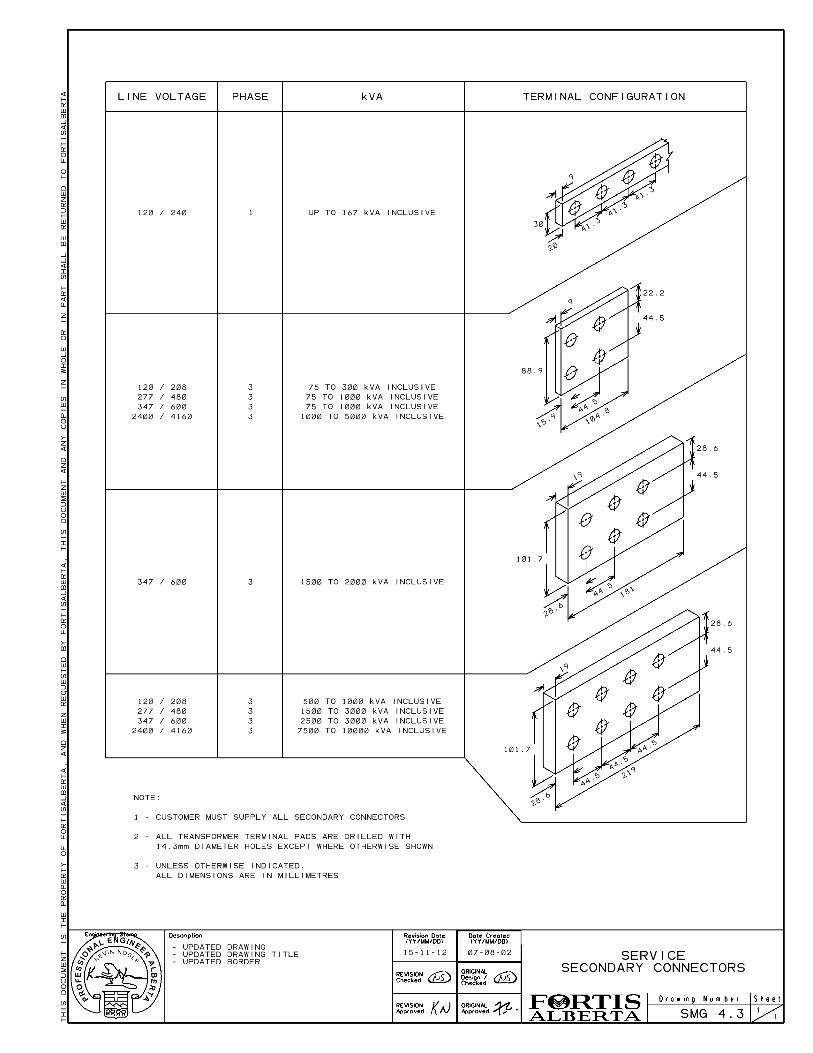
Supply the transformer terminal connectors.
If the Customer service is supplied with a dedicated transformer the Customer may opt to have FortisAlberta install padmount metering on the transformer. Padmount metering will be quoted as Optional Facilities.
If the Customer service is supplied with a dedicated transformer the Customer will install and connect the underground secondary cable at the transformer secondary terminals or padmount meter. A written work “Guarantee of Isolation” shall be obtained from FortisAlberta before entering the transformer enclosure. With a written “Guarantee of Isolation” the Customer may then connect the underground secondary cables to the transformer secondary terminals (refer to Drawing # SMG 4.3). o The cables shall be supported below the transformer terminals, as the
transformer terminals cannot support the weight of the cables.
For Customer lot-line metering, supply and install lot-line metering apparatus. (Refer to Drawing # SMG 2.1).
4.4 Multiple Residential Service Sites
All multiple residential services shall be designed and constructed for individually metered units and residences. The meters and equipment for multiple residential services are required to meet the requirements of Section 2.0 in addition to the following:
FortisAlberta
Alberta Service and Metering Guide
Revision Date: November 2015 Version No.: 4.0
This document is the property of FortisAlberta for authorized used only. This is an uncontrolled printed copy (printed on 2015/11/12 at 4:44 PM) and may be out of date. See the electronic copy of this document on the FortisAlberta web site at fortisalberta.com for the current official version.
Page 31 .
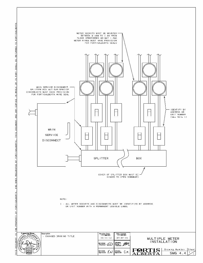
4.4.1 Meter Location The meters shall be located indoors, grouped together in an approved location and connected on the load side of the sub-service disconnect. The main switch, splitter box, and sub-service disconnects shall have provision for FortisAlberta seals. All meter sockets shall be identified by address or unit number with a permanent legible label on all meter sockets and all disconnects (refer to Section 2.15 and Drawing # SMG 4.4).
4.4.2 Duplex to Fiveplex In the case of a duplex to fiveplex (2-5 units), the meters can be located outdoors and be connected on the line side of the service disconnect.
All ganged meter sockets must have shields or insulation to protect flash points resulting from misaligning socket covers during insertion of same. All service entrance equipment sections ahead of the metering point shall be equipped with provisions for FortisAlberta seals.
5.0 Farm Services
5.1 Overhead Farm Service Supplied by an Overhead Transformer
The Customer shall:
Supply the overhead service wire from each service entrance to the metering pole. FortisAlberta shall:
Supply and install the service pole (if required), meter and the farm/rural meter box.
Connect the overhead service wire at the transformer.
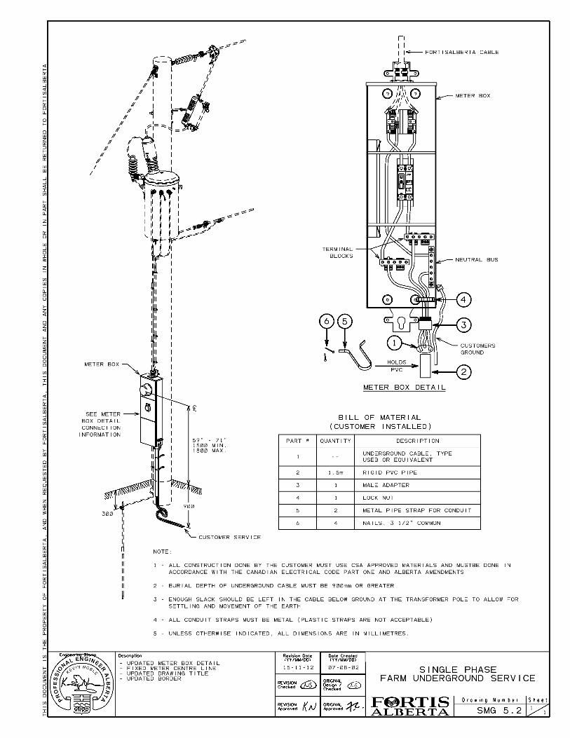
5.2 Underground Farm Service Supplied by an Overhead Transformer
The Customer shall:
Supply and install the underground cable up to the farm/rural meter box located on the transformer pole.
Supply and install the conduit up the pole to the farm/rural meter box.
Connect the underground cable at the farm meter box (splitter section). FortisAlberta shall:
Supply and install the meter and the farm/rural meter box (refer to Drawing # SMG 5.2).
FortisAlberta
Alberta Service and Metering Guide
Revision Date: November 2015 Version No.: 4.0
This document is the property of FortisAlberta for authorized used only. This is an uncontrolled printed copy (printed on 2015/11/12 at 4:44 PM) and may be out of date. See the electronic copy of this document on the FortisAlberta web site at fortisalberta.com for the current official version.
Page 32 .
5.3 Underground Farm Service Supplied by a Padmount Transformer
The Customer shall:
Supply and install the underground secondary cable up to the metering pedestal or padmount meter located near or on the underground padmount transformer.
Install the underground secondary cable into the metering structure. FortisAlberta shall:
Supply and install the meter and the metering pedestal or padmount meter.
Inspect the installation of the underground secondary cable into the secondary compartment (refer to Drawing # SMG 5.2).
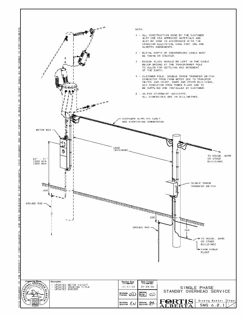
6.0 Transfer Switches and Standby Generators
The following requirements are the Customers responsibility in addition to the standard requirements for each type of service. These requirements apply to new services with standby generators:
Maintenance and repair of the switching equipment.
Supply circuit from the standby plant to the transfer switch cannot be run overhead to the pole where the switch is mounted. It is to be either an underground circuit or a plug-in type connection.
Secondary cables on the load side of the generator cannot be attached to the transformer pole.
The standby service structure and the generator shall not be installed within a 5 m radius of the transformer pole. The distribution point cannot be located on the FortisAlberta owned service structure.
If transfer switch is comprised of two molded case breakers they shall be tied together mechanically (inter-locked) to prevent both breakers from being closed at the same time.
The size and type of switch shall be suitable for the installation.
The enclosure shall be capable of being sealed.
The double throw transfer switch shall be attached to the standby service structure.
Source circuits from FortisAlberta and the Customer’s standby may not be installed in a common conduit.
An electrical permit or a signed Connection Authorization Form for the installation is required before FortisAlberta can complete the connection.
FortisAlberta
Alberta Service and Metering Guide
Revision Date: November 2015 Version No.: 4.0
This document is the property of FortisAlberta for authorized used only. This is an uncontrolled printed copy (printed on 2015/11/12 at 4:44 PM) and may be out of date. See the electronic copy of this document on the FortisAlberta web site at fortisalberta.com for the current official version.
Page 33 .
The Customer shall:
Supply and install weatherproof double throw transfer switch, and
Supply and install the standby service structure (i.e. pole stub, building) to support double throw transfer switch.
FortisAlberta shall:
Verify all connections in the double throw transfer switch (refer to Drawing # SMG 6.0.1 and SMG 6.0.2)
Install warning sticker (item no. 491-1925) on transfer switch and warning label (Item no. 491-0315) indicating standby plant exists on the farm meter box.
Seal the Customer supplied weatherproof double throw transfer switch.
6.1.1 Overhead Standby Generator Service Supplied by an Overhead Transformer
The Customer shall:
Supply the appropriate length of overhead service wire from the standby service up to the transformer secondary bushing.
Make the connection at the standby service structure. FortisAlberta shall:
Connect the overhead service wire at the transformer pole.
6.1.2 Underground Standby Generator Service Supplied by an Overhead Transformer
The Customer shall:
Supply and install the conduit up the pole to the farm/rural meter box.
Supply and install the underground cable from the transformer pole to the standby service structure.
Connect the underground cable at the farm meter box.
Connect the underground cable at the standby service structure.
FortisAlberta shall:
Supply and install the meter and the farm/rural meter box (Drawing # SMG 5.2).
Connect farm and rural meter box to the transformer.
FortisAlberta
Alberta Service and Metering Guide
Revision Date: November 2015 Version No.: 4.0
This document is the property of FortisAlberta for authorized used only. This is an uncontrolled printed copy (printed on 2015/11/12 at 4:44 PM) and may be out of date. See the electronic copy of this document on the FortisAlberta web site at fortisalberta.com for the current official version.
Page 34 .
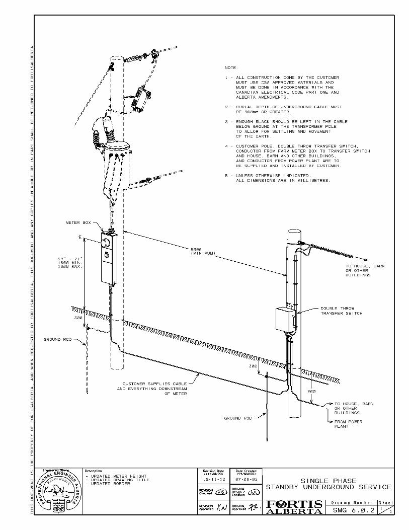
6.1.3 Underground Standby Generator Service Supplied by a Padmount Transformer
The Customer shall:
Supply and install the underground cable from the farm metering pedestal to the double throw transfer switch.
Connect the underground secondary cable at the double throw transfer switch.
Install the underground secondary cable into the farm metering pedestal. FortisAlberta shall:
Supply and install the meter and the farm metering pedestal.
Inspect the installation of the underground secondary cable into the secondary compartment (Drawing # SMG 5.2).
7.0 Commercial Services
The following applies to Single and Three Phase Commercial, Industrial, Oil & Gas, Irrigation, Bare land, and Apartment Building services.
7.1 Overhead Service Supplied by an Overhead Transformer
The Customer shall:
Supply and install the meter socket.
Supply and install a metallic service entrance mast complete with weather head, clevis insulator and cable. The service mast or clevis insulator complete with bolt, shall be securely fastened to the building. Note: Screw type insulators (service knobs) will not be accepted on new or upgraded construction.
For Customer pole metering, supply and install metering pole (Drawing # SMG 4.1).
FortisAlberta shall:
Supply and install the meter.
Supply and install up to 60 m of secondary cable with any one span being a maximum of 30 m. FortisAlberta will not supply any service pole(s) for Commercial, Industrial, Oil & Gas, Irrigation, Bare land, and Apartment Building services.
FortisAlberta
Alberta Service and Metering Guide
Revision Date: November 2015 Version No.: 4.0
This document is the property of FortisAlberta for authorized used only. This is an uncontrolled printed copy (printed on 2015/11/12 at 4:44 PM) and may be out of date. See the electronic copy of this document on the FortisAlberta web site at fortisalberta.com for the current official version.
Page 35 .
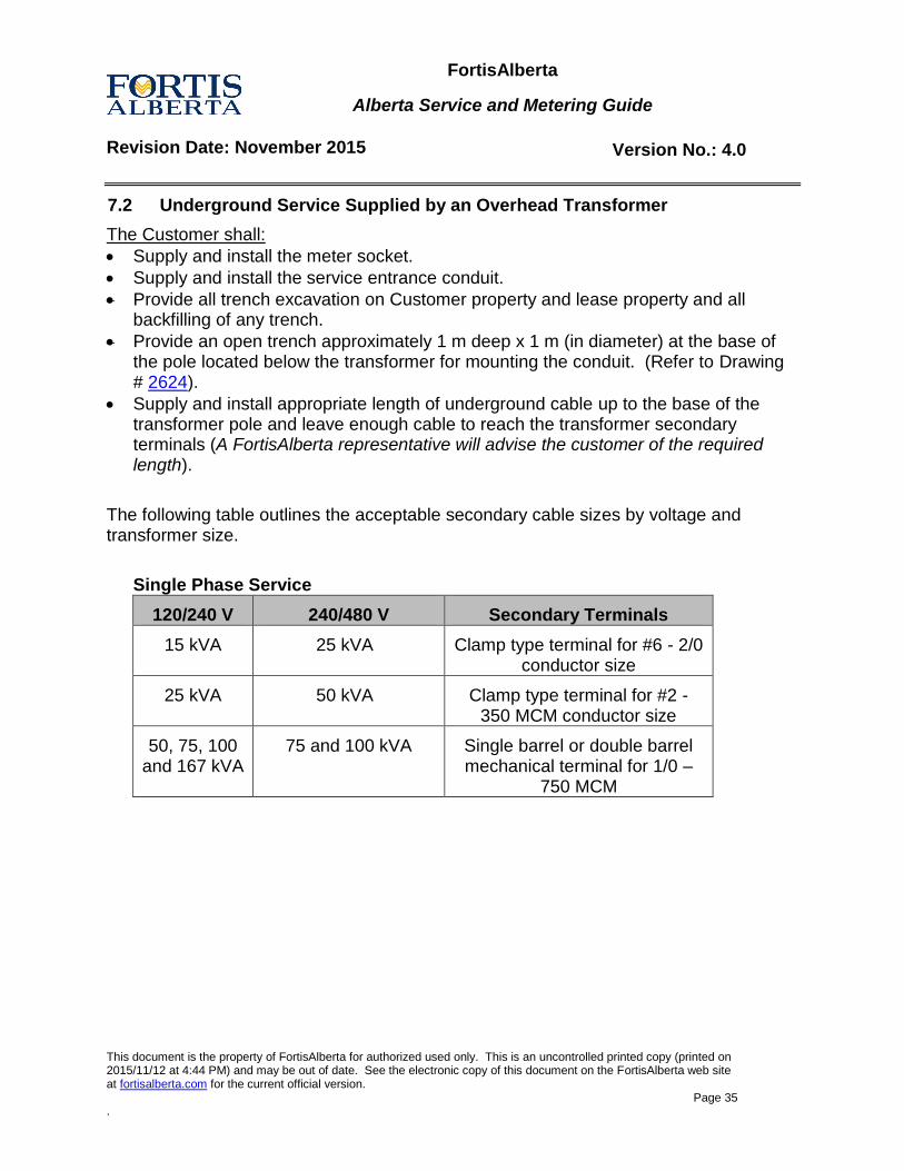
7.2 Underground Service Supplied by an Overhead Transformer
The Customer shall:
Supply and install the meter socket.
Supply and install the service entrance conduit.
Provide all trench excavation on Customer property and lease property and all backfilling of any trench.
Provide an open trench approximately 1 m deep x 1 m (in diameter) at the base of the pole located below the transformer for mounting the conduit. (Refer to Drawing # 2624).
Supply and install appropriate length of underground cable up to the base of the transformer pole and leave enough cable to reach the transformer secondary terminals (A FortisAlberta representative will advise the customer of the required length).
The following table outlines the acceptable secondary cable sizes by voltage and transformer size.
Single Phase Service
120/240 V 240/480 V Secondary Terminals
15 kVA 25 kVA Clamp type terminal for #6 - 2/0 conductor size
25 kVA 50 kVA Clamp type terminal for #2 - 350 MCM conductor size
50, 75, 100 and 167 kVA
75 and 100 kVA Single barrel or double barrel mechanical terminal for 1/0 –
750 MCM
FortisAlberta
Alberta Service and Metering Guide
Revision Date: November 2015 Version No.: 4.0
This document is the property of FortisAlberta for authorized used only. This is an uncontrolled printed copy (printed on 2015/11/12 at 4:44 PM) and may be out of date. See the electronic copy of this document on the FortisAlberta web site at fortisalberta.com for the current official version.
Page 36 .
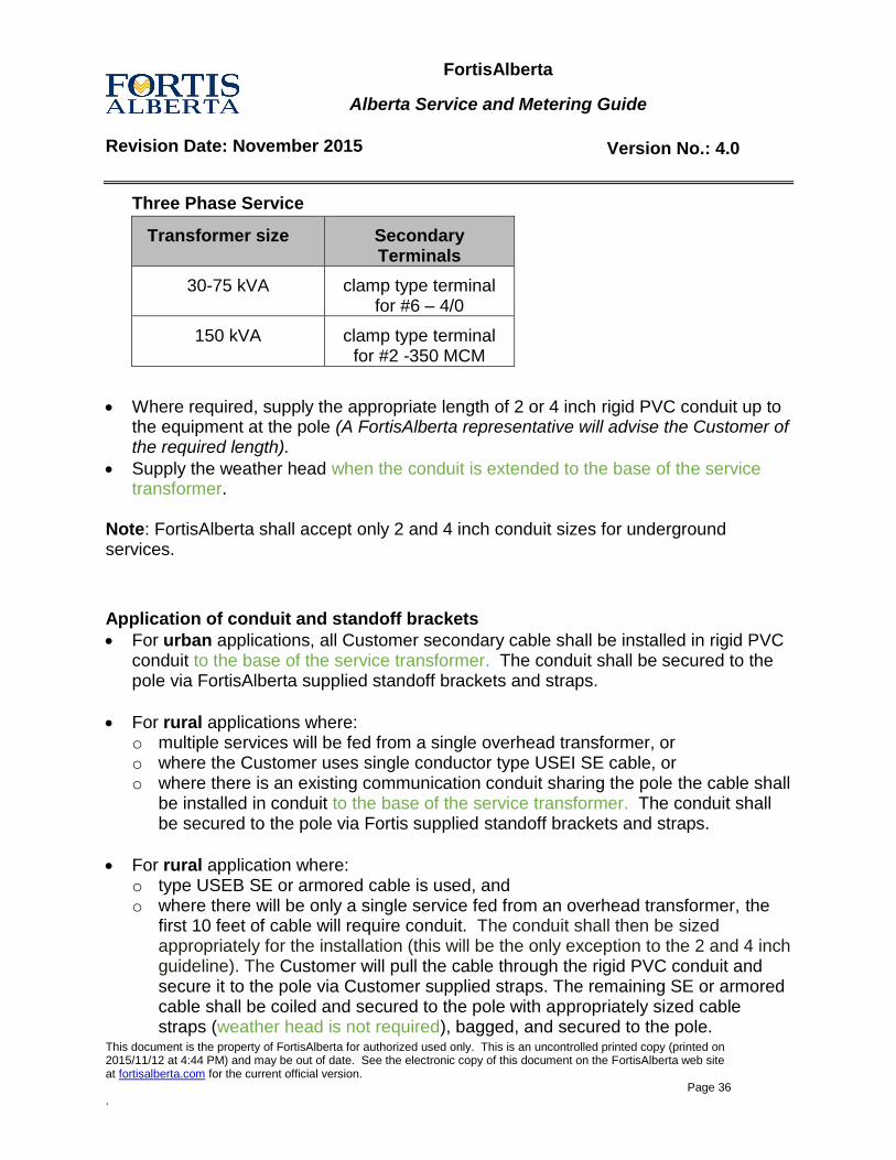
Three Phase Service
Where required, supply the appropriate length of 2 or 4 inch rigid PVC conduit up to the equipment at the pole (A FortisAlberta representative will advise the Customer of the required length).
Supply the weather head when the conduit is extended to the base of the service transformer.
Note: FortisAlberta shall accept only 2 and 4 inch conduit sizes for underground services.
Application of conduit and standoff brackets
For urban applications, all Customer secondary cable shall be installed in rigid PVC conduit to the base of the service transformer. The conduit shall be secured to the pole via FortisAlberta supplied standoff brackets and straps.
For rural applications where: o multiple services will be fed from a single overhead transformer, or o where the Customer uses single conductor type USEI SE cable, or o where there is an existing communication conduit sharing the pole the cable shall
be installed in conduit to the base of the service transformer. The conduit shall be secured to the pole via Fortis supplied standoff brackets and straps.
For rural application where: o type USEB SE or armored cable is used, and o where there will be only a single service fed from an overhead transformer, the
first 10 feet of cable will require conduit. The conduit shall then be sized appropriately for the installation (this will be the only exception to the 2 and 4 inch guideline). The Customer will pull the cable through the rigid PVC conduit and secure it to the pole via Customer supplied straps. The remaining SE or armored cable shall be coiled and secured to the pole with appropriately sized cable straps (weather head is not required), bagged, and secured to the pole.
Transformer size Secondary Terminals
30-75 kVA clamp type terminal for #6 – 4/0
150 kVA clamp type terminal for #2 -350 MCM
FortisAlberta
Alberta Service and Metering Guide
Revision Date: November 2015 Version No.: 4.0
This document is the property of FortisAlberta for authorized used only. This is an uncontrolled printed copy (printed on 2015/11/12 at 4:44 PM) and may be out of date. See the electronic copy of this document on the FortisAlberta web site at fortisalberta.com for the current official version.
Page 37 .
If the customer chooses to use multi conductor armored cable then the last 2 m of the cable must be stripped of the cable armor exposing the PVC inner jacket. The PVC jacket shall then be covered with color coded heat shrink tubing. o The conductor intended to be used as the neutral shall be clearly identifiable via
white vinyl tape or heat shrink tubing. o Warning - the PVC colour coded insulation used for TECK 90 (copper) cables is
not suitable for UV exposure and will deteriorate over time breaking down the insulation and exposing the conductor.
No person except FortisAlberta personnel shall climb the transformer pole.
FortisAlberta shall complete the final transformer connection.
For Customer lot-line metering, supply and install lot-line metering apparatus. (Refer to Drawing # SMG 2.1).
FortisAlberta shall:
Supply and install the meter.
Where applicable, supply and install standoff brackets and mounting hardware suitable for 2” and 4” conduit.
Where required, assemble full height conduit riser way, pull in the cable, install weather head and mount.
Where only 10 ft of conduit is required, FortisAlberta shall secure the remainder of the cable to the pole using Customer supplied cable straps.
Connect the underground cable to the transformer secondary terminals.
7.3 Underground Service Supplied by a Padmount Transformer
The Customer shall:
All underground primary installations need to follow the procedures and requirements outlined in “Customer Installed Pre-cast Bases, Grounding and Ducting Process”.
Contact FortisAlberta to arrange an on-site meeting with a FortisAlberta design representative prior to any construction. Supply the FortisAlberta representative with a preliminary site plan complete with building locations, transformer location and duct location.
Have all service details accepted by FortisAlberta prior to the start of any construction.
Provide all trench excavation on Customer property.
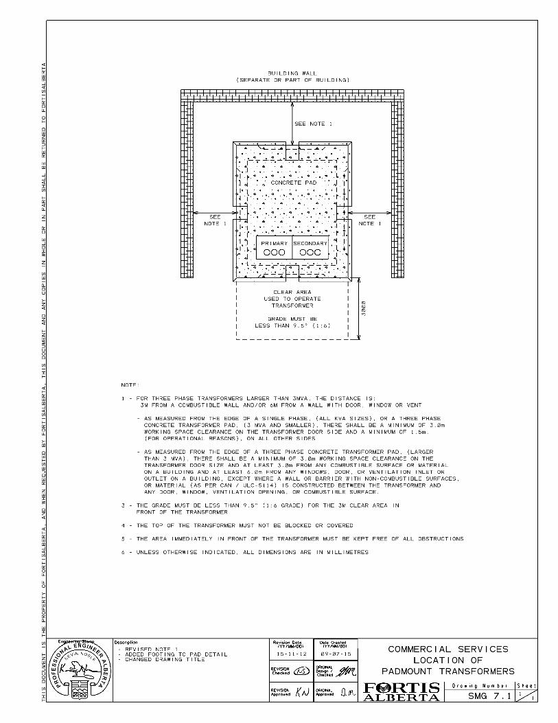
Maintain a clear operating area (refer Drawing # SMG 7.1).
FortisAlberta
Alberta Service and Metering Guide
Revision Date: November 2015 Version No.: 4.0
This document is the property of FortisAlberta for authorized used only. This is an uncontrolled printed copy (printed on 2015/11/12 at 4:44 PM) and may be out of date. See the electronic copy of this document on the FortisAlberta web site at fortisalberta.com for the current official version.
Page 38 .
FortisAlberta shall:
Determine location of point of entry to Customer’s property.
Accept Customer's construction details.
Determine the offsite facilities needed based on the preliminary plan. FortisAlberta shall also provide the type of grounding system that is required (single ring or three ring).
Provide all offsite work.
Pull primary cables through duct from property line to transformer location.
Install transformer on pad and perform all primary connections.
Issue a “Guarantee of Isolation” upon request.
Inspect installation and connection of the underground cable into the transformer secondary compartment.
For Customer lot-line metering, supply and install the underground cable on public property.
If ground testing and report was not done by the Customer, FortisAlberta shall test Customer grounds and upgrade if necessary at Customer's expense.
Supply and install the meter.
Reserve the right to inspect the installation of any Customer installed facilities.
FortisAlberta
Alberta Service and Metering Guide
Revision Date: November 2015 Version No.: 4.0
This document is the property of FortisAlberta for authorized used only. This is an uncontrolled printed copy (printed on 2015/11/12 at 4:44 PM) and may be out of date. See the electronic copy of this document on the FortisAlberta web site at fortisalberta.com for the current official version.
Page 39 .
7.4 Metering Requirements for less than 300V Services
Single meter commercial services rated less than 300 V are required to meet the following: 1. Meter shall be located outdoors on either:
the outside wall of a suitable building with a clear area free of vents (refer to Drawing # SMG 2.16.4 page 2), or
a separate suitable stand-alone metering structure located a minimum distance of 5 m from the transformer pole or concrete pad.
2. Meter shall be connected on the line side of the service disconnect. 3. Meter shall be mounted with the center line of the meter at a height specified in
Table 2.0. The minimum height as specified must be maintained when final grade is reached.
7.5 Metering Requirements for Greater than 300V, Services
The metering equipment for services exceeding 300 V are required to meet the following: 1. Located indoors; except for oilfield and irrigation services, where the meter may be
located on the outside wall of a suitable building with an clear area free of vents (refer to Drawing # SMG 2.16.4 page 2), directly opposite and connected downstream of the main breaker, or outdoors on a stand-alone metering structure 5 m minimum away from the transformer pole (refer to Drawing # SMG 2.13.5).
2. For irrigation services, the distribution center for the motors shall be installed at the meter location, or an extra service disconnect is required on the load side of the meter (Drawing # SMG 2.13.5).
3. Mounted with the center line of the meter at a height specified in Table 2.0. 4. Equipped with provisions for FortisAlberta to seal all service entrance equipment
ahead of the metering point.
FortisAlberta
Alberta Service and Metering Guide
Revision Date: November 2015 Version No.: 4.0
This document is the property of FortisAlberta for authorized used only. This is an uncontrolled printed copy (printed on 2015/11/12 at 4:44 PM) and may be out of date. See the electronic copy of this document on the FortisAlberta web site at fortisalberta.com for the current official version.
Page 40 .
7.6 Instrument Metering Requirements
The Customer shall supply:
An approved instrument meter socket as specified in (Section 11.1) or combination unit.
An instrument transformer enclosure (refer to Section 2.16.3, Instrument Transformer Enclosures (Indoor), Section 2.16.4, Instrument Transformer Enclosures (Outdoor) and Section 2.16.5 Required Instrument Transformer Enclosure Sizes .
A 35 mm (1 ¼ “) conduit between the instrument transformer enclosure and the meter socket.
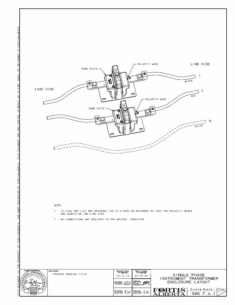
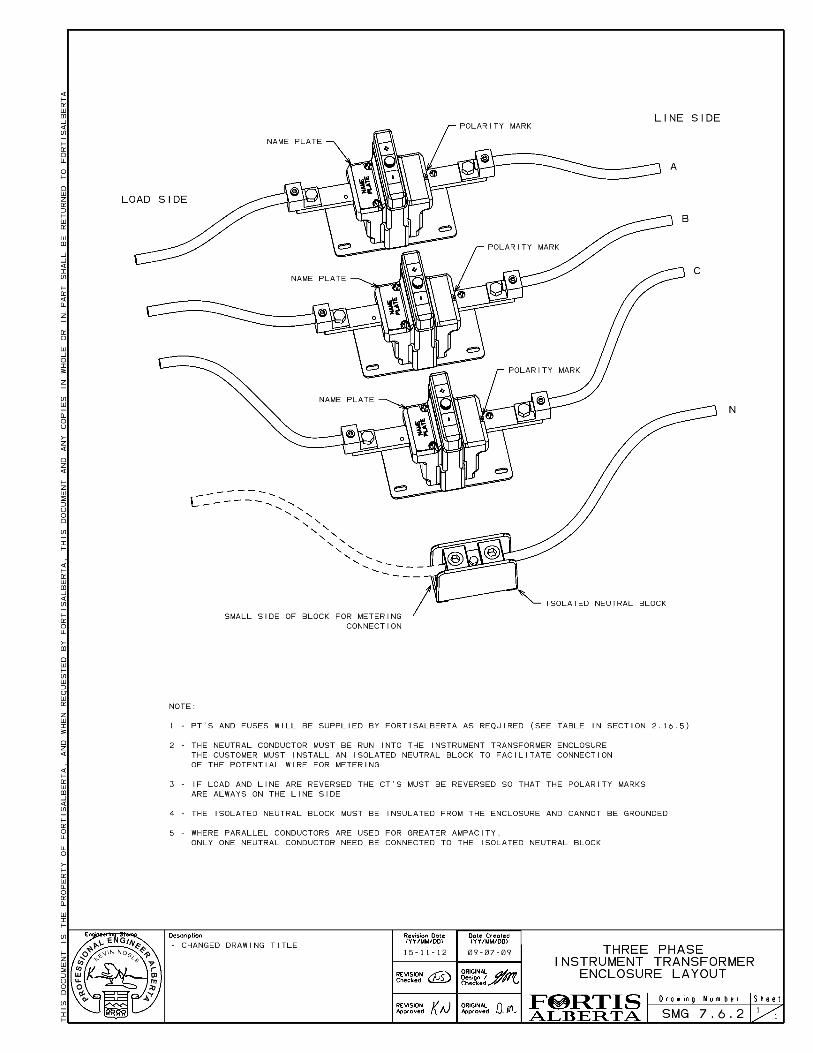
Install an isolated neutral block in the instrument transformer enclosure (3 phase services only & only one parallel conductor needs to be attached).
All hardware, bus work, terminations and/or cable required for primary connections to the current transformers.
19 mm (3/4”) plywood behind all instrument transformer enclosures when mounted on cement/block wall.
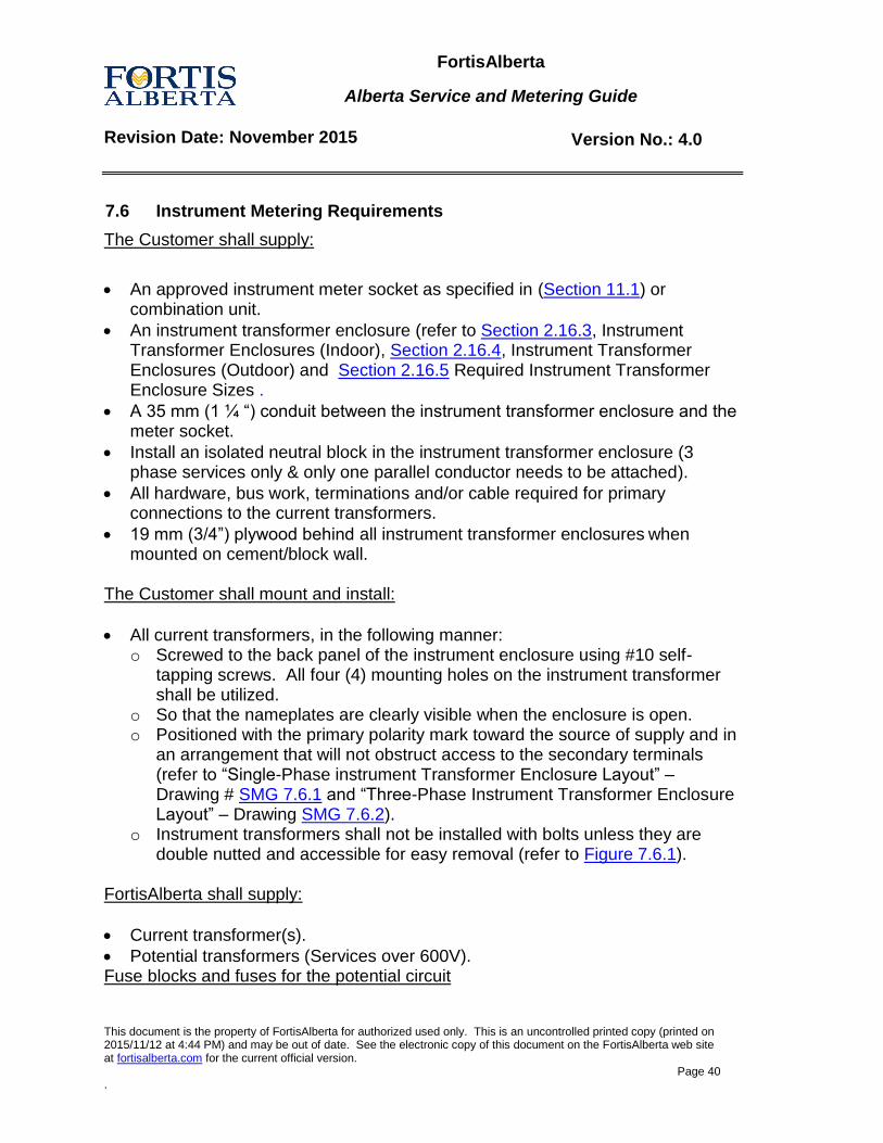
The Customer shall mount and install:
All current transformers, in the following manner: o Screwed to the back panel of the instrument enclosure using #10 self-
tapping screws. All four (4) mounting holes on the instrument transformer shall be utilized.
o So that the nameplates are clearly visible when the enclosure is open. o Positioned with the primary polarity mark toward the source of supply and in
an arrangement that will not obstruct access to the secondary terminals (refer to “Single-Phase instrument Transformer Enclosure Layout” – Drawing # SMG 7.6.1 and “Three-Phase Instrument Transformer Enclosure Layout” – Drawing SMG 7.6.2).
o Instrument transformers shall not be installed with bolts unless they are double nutted and accessible for easy removal (refer to Figure 7.6.1).
FortisAlberta shall supply:
Current transformer(s).
Potential transformers (Services over 600V). Fuse blocks and fuses for the potential circuit
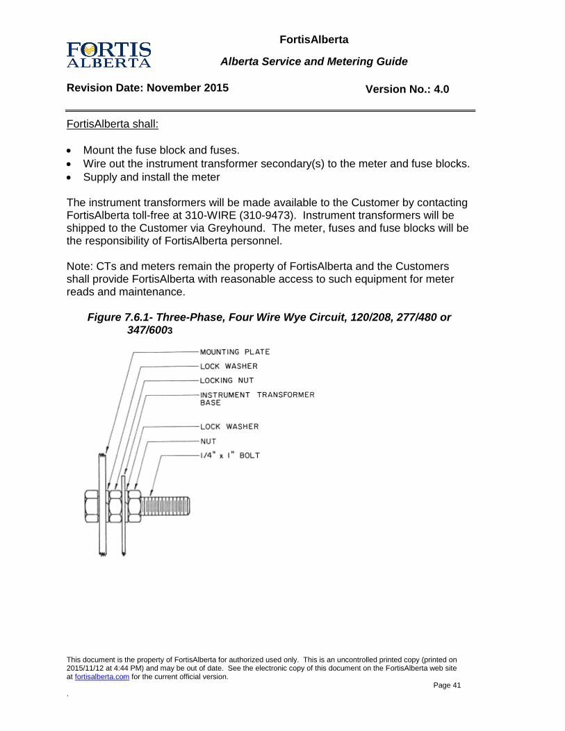
FortisAlberta
Alberta Service and Metering Guide
Revision Date: November 2015 Version No.: 4.0
This document is the property of FortisAlberta for authorized used only. This is an uncontrolled printed copy (printed on 2015/11/12 at 4:44 PM) and may be out of date. See the electronic copy of this document on the FortisAlberta web site at fortisalberta.com for the current official version.
Page 41 .
FortisAlberta shall:
Mount the fuse block and fuses.
Wire out the instrument transformer secondary(s) to the meter and fuse blocks.
Supply and install the meter
The instrument transformers will be made available to the Customer by contacting FortisAlberta toll-free at 310-WIRE (310-9473). Instrument transformers will be shipped to the Customer via Greyhound. The meter, fuses and fuse blocks will be the responsibility of FortisAlberta personnel. Note: CTs and meters remain the property of FortisAlberta and the Customers shall provide FortisAlberta with reasonable access to such equipment for meter reads and maintenance.
Figure 7.6.1- Three-Phase, Four Wire Wye Circuit, 120/208, 277/480 or
347/6003
FortisAlberta
Alberta Service and Metering Guide
Revision Date: November 2015 Version No.: 4.0
This document is the property of FortisAlberta for authorized used only. This is an uncontrolled printed copy (printed on 2015/11/12 at 4:44 PM) and may be out of date. See the electronic copy of this document on the FortisAlberta web site at fortisalberta.com for the current official version.
Page 42 .
8.0 Metering Signal Service Offer
8.1 Availability of metering signals
FortisAlberta shall provide Metering Signals to Customers, upon request. These signals are in the form of energy (kWh) or reactive energy (kVARh - standard or kVAh in limited applications) pulses for use as an energy management tool. Incremental costs incurred by FortisAlberta for providing these signals will be the responsibility of the Customer. FortisAlberta shall not supply an End-of-Interval (EOI) pulse under any circumstances.
8.2 Process
Upon receipt of a formal request for a metering signal quote (310-WIRE), FortisAlberta shall develop a cost breakdown for the Radio Frequency Metering Signal Service Offer. The quote will clearly identify technical issues, specifications and any other additional cost factors, which will be at the Customer’s expense. Once all the technical issues are addressed, FortisAlberta shall forward the offer to the Customer. This will include the quotation letter, a copy of “Technical Specifications - Schedule B”, a site schematic (if applicable) and a copy of “Conditions for Metering Signals - Schedule A”. Upon receipt of the Customer’s acceptance, FortisAlberta shall install the service. The signal will be terminated in a junction box to be located in or attached to the metering equipment. All equipment up to, and including this termination, will remain the property of FortisAlberta.
8.3 Radio Frequency (RF) Communication Installation
FortisAlberta cannot guarantee good reception via wireless communication devices at any site and the Customer agrees to this potential limitation by accepting the offer. Any communication circuit troubleshooting time, requiring FortisAlberta’s Field Metering Technologist to stay on site beyond the time assigned for the installation the communication equipment, will be billed to the Customer separately. The installation of any equipment or cabling on FortisAlberta premises will be done in conjunction and at the same time as the FortisAlberta Field Metering Technologist installing the service; otherwise additional costs may be incurred.
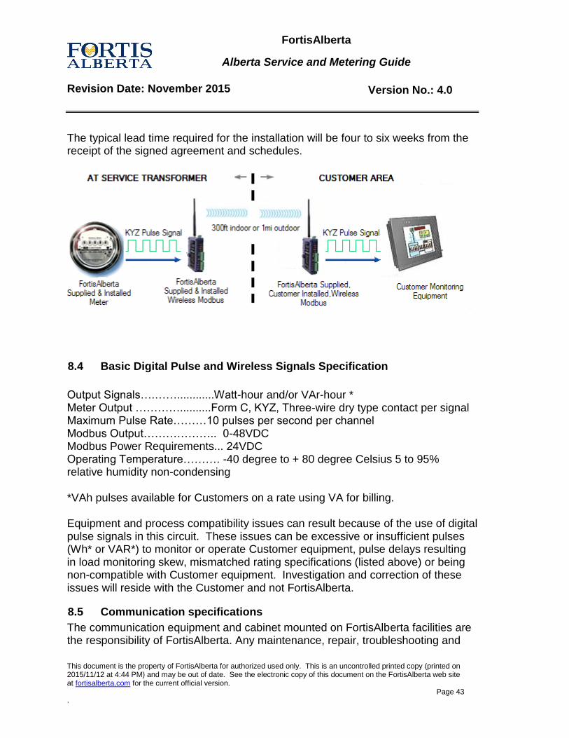
FortisAlberta
Alberta Service and Metering Guide
Revision Date: November 2015 Version No.: 4.0
This document is the property of FortisAlberta for authorized used only. This is an uncontrolled printed copy (printed on 2015/11/12 at 4:44 PM) and may be out of date. See the electronic copy of this document on the FortisAlberta web site at fortisalberta.com for the current official version.
Page 43 .
The typical lead time required for the installation will be four to six weeks from the receipt of the signed agreement and schedules.
8.4 Basic Digital Pulse and Wireless Signals Specification
Output Signals….……............Watt-hour and/or VAr-hour * Meter Output …………..........Form C, KYZ, Three-wire dry type contact per signal Maximum Pulse Rate………10 pulses per second per channel Modbus Output……………….. 0-48VDC Modbus Power Requirements... 24VDC Operating Temperature………. -40 degree to + 80 degree Celsius 5 to 95% relative humidity non-condensing *VAh pulses available for Customers on a rate using VA for billing. Equipment and process compatibility issues can result because of the use of digital pulse signals in this circuit. These issues can be excessive or insufficient pulses (Wh* or VAR*) to monitor or operate Customer equipment, pulse delays resulting in load monitoring skew, mismatched rating specifications (listed above) or being non-compatible with Customer equipment. Investigation and correction of these issues will reside with the Customer and not FortisAlberta.
8.5 Communication specifications
The communication equipment and cabinet mounted on FortisAlberta facilities are the responsibility of FortisAlberta. Any maintenance, repair, troubleshooting and
FortisAlberta
Alberta Service and Metering Guide
Revision Date: November 2015 Version No.: 4.0
This document is the property of FortisAlberta for authorized used only. This is an uncontrolled printed copy (printed on 2015/11/12 at 4:44 PM) and may be out of date. See the electronic copy of this document on the FortisAlberta web site at fortisalberta.com for the current official version.
Page 44 .
modifications to the communication equipment located on Customer facilities will be the responsibility of the Customer.
8.6 Disclaimer
The Customer acknowledges that the metering signal(s) provided to the Customer pursuant to the agreement are not used for measuring the Customer’s electricity consumption or calculating charges for the Customer’s electricity consumption. The metering signal(s) are provided solely for the Customer’s internal use to assist the Customer in monitoring their energy consumption. The Customer further acknowledges that FortisAlberta assumes absolutely no liability whatsoever for any inaccuracy with respect to the information obtained from the metering signals or for the Customer’s use of the metering signal(s). FortisAlberta shall not be obligated to reduce higher registered demand peaks or higher energy consumptions which are inadvertently set as a result of metering signal equipment failure.
9.0 Temporary Services
The following applies to temporary services for Residential, Single and Three Phase Commercial, Industrial, Oil & Gas, Irrigation, Bare land, and Apartment Building services.
9.1 General requirements
The Customer shall:
Supply and install the temporary pole or temporary stub to support the meter socket.
Supply and install meter socket and secondary protection including grounds.
Provide a valid electrical permit or a signed connection authorization form.
These requirements are in addition to the standard requirements for each type of service.
9.2 Overhead Services Supplied by an Overhead Transformer
The Customer shall:
Supply and install the temporary pole.
Supply the overhead service wire from the temporary pole to the transformer pole. Coil wire at base of temporary pole or mast.
FortisAlberta shall:
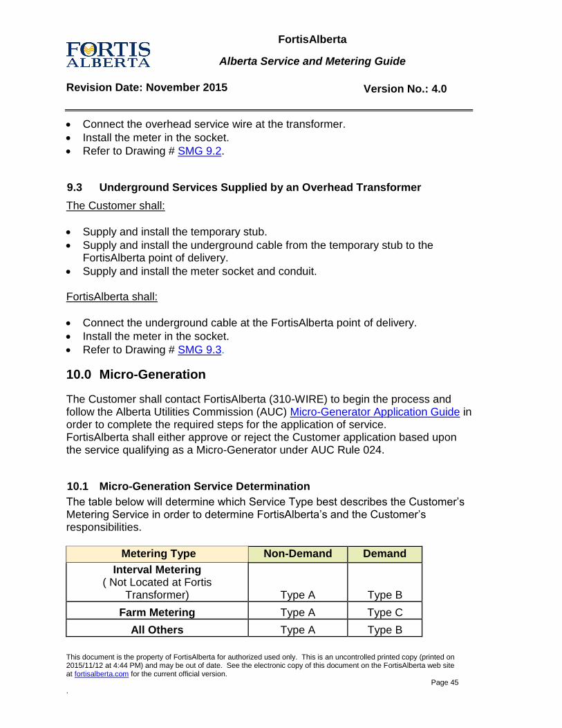
FortisAlberta
Alberta Service and Metering Guide
Revision Date: November 2015 Version No.: 4.0
This document is the property of FortisAlberta for authorized used only. This is an uncontrolled printed copy (printed on 2015/11/12 at 4:44 PM) and may be out of date. See the electronic copy of this document on the FortisAlberta web site at fortisalberta.com for the current official version.
Page 45 .
Connect the overhead service wire at the transformer.
Install the meter in the socket.
Refer to Drawing # SMG 9.2.
9.3 Underground Services Supplied by an Overhead Transformer
The Customer shall:
Supply and install the temporary stub.
Supply and install the underground cable from the temporary stub to the FortisAlberta point of delivery.
Supply and install the meter socket and conduit. FortisAlberta shall:
Connect the underground cable at the FortisAlberta point of delivery.
Install the meter in the socket.
Refer to Drawing # SMG 9.3.
10.0 Micro-Generation
The Customer shall contact FortisAlberta (310-WIRE) to begin the process and follow the Alberta Utilities Commission (AUC) Micro-Generator Application Guide in order to complete the required steps for the application of service. FortisAlberta shall either approve or reject the Customer application based upon the service qualifying as a Micro-Generator under AUC Rule 024.
10.1 Micro-Generation Service Determination
The table below will determine which Service Type best describes the Customer’s Metering Service in order to determine FortisAlberta’s and the Customer’s responsibilities.
Metering Type Non-Demand Demand
Interval Metering ( Not Located at Fortis
Transformer) Type A Type B
Farm Metering Type A Type C
All Others Type A Type B
FortisAlberta
Alberta Service and Metering Guide
Revision Date: November 2015 Version No.: 4.0
This document is the property of FortisAlberta for authorized used only. This is an uncontrolled printed copy (printed on 2015/11/12 at 4:44 PM) and may be out of date. See the electronic copy of this document on the FortisAlberta web site at fortisalberta.com for the current official version.
Page 46 .
10.2 Type-A Responsibilities
For new services the Customer shall supply and install their service equipment according to all relevant sections of this publication. For existing services the Customer is not required to make any modification to their metering equipment. Once the service is approved as a Micro-Generator, FortisAlberta shall supply and install a bi-directional meter to measure service load and export power.
10.3 Type-B Responsibilities
For new services the Customer shall supply and install their service equipment according to all relevant sections of this publication. In addition, for both new and existing services the Customer shall install a dual meter socket wired as per Figure 10.3.1. Refer to Figure 10.3.2 for an example Underground installation drawing. Figure 10.3.3 shows a typical SLD of a Micro-Generation installation. Note: Section 2.4, CSA Approved Device and Meter Socket Requirements must be followed when making any modifications to meter sockets. Once the service is approved as a Micro-Generator FortisAlberta shall supply and install two meters to measure service load and export.
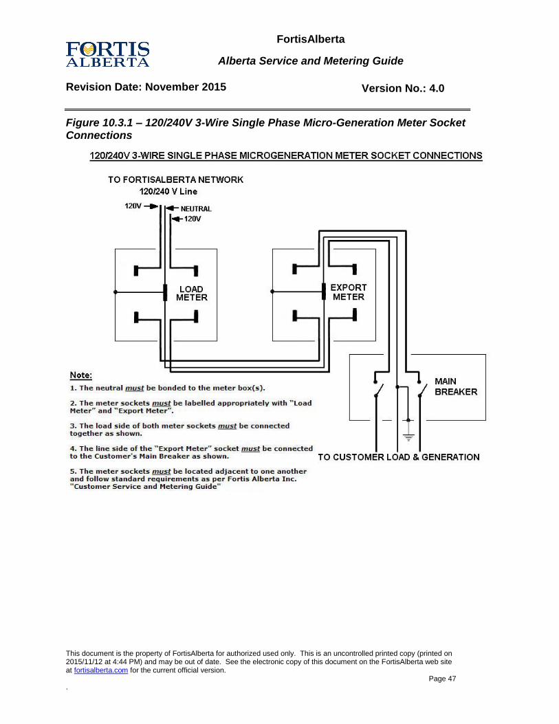
FortisAlberta
Alberta Service and Metering Guide
Revision Date: November 2015 Version No.: 4.0
This document is the property of FortisAlberta for authorized used only. This is an uncontrolled printed copy (printed on 2015/11/12 at 4:44 PM) and may be out of date. See the electronic copy of this document on the FortisAlberta web site at fortisalberta.com for the current official version.
Page 47 .
Figure 10.3.1 – 120/240V 3-Wire Single Phase Micro-Generation Meter Socket Connections
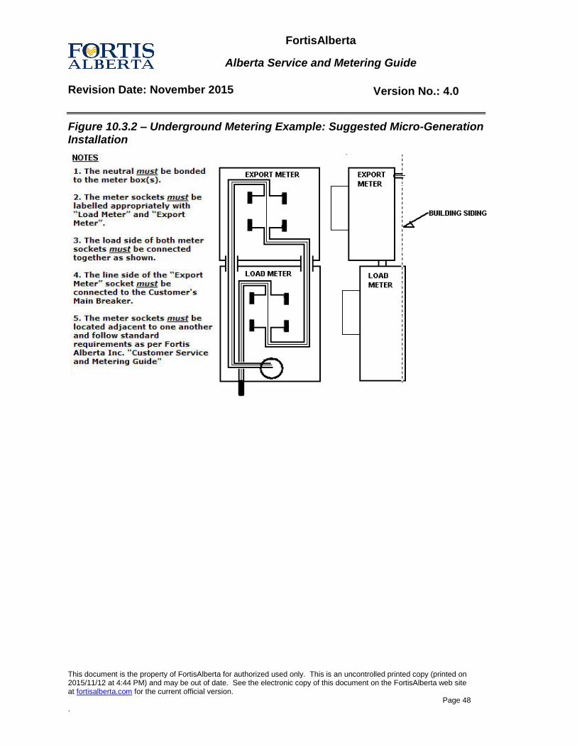
FortisAlberta
Alberta Service and Metering Guide
Revision Date: November 2015 Version No.: 4.0
This document is the property of FortisAlberta for authorized used only. This is an uncontrolled printed copy (printed on 2015/11/12 at 4:44 PM) and may be out of date. See the electronic copy of this document on the FortisAlberta web site at fortisalberta.com for the current official version.
Page 48 .
Figure 10.3.2 – Underground Metering Example: Suggested Micro-Generation Installation
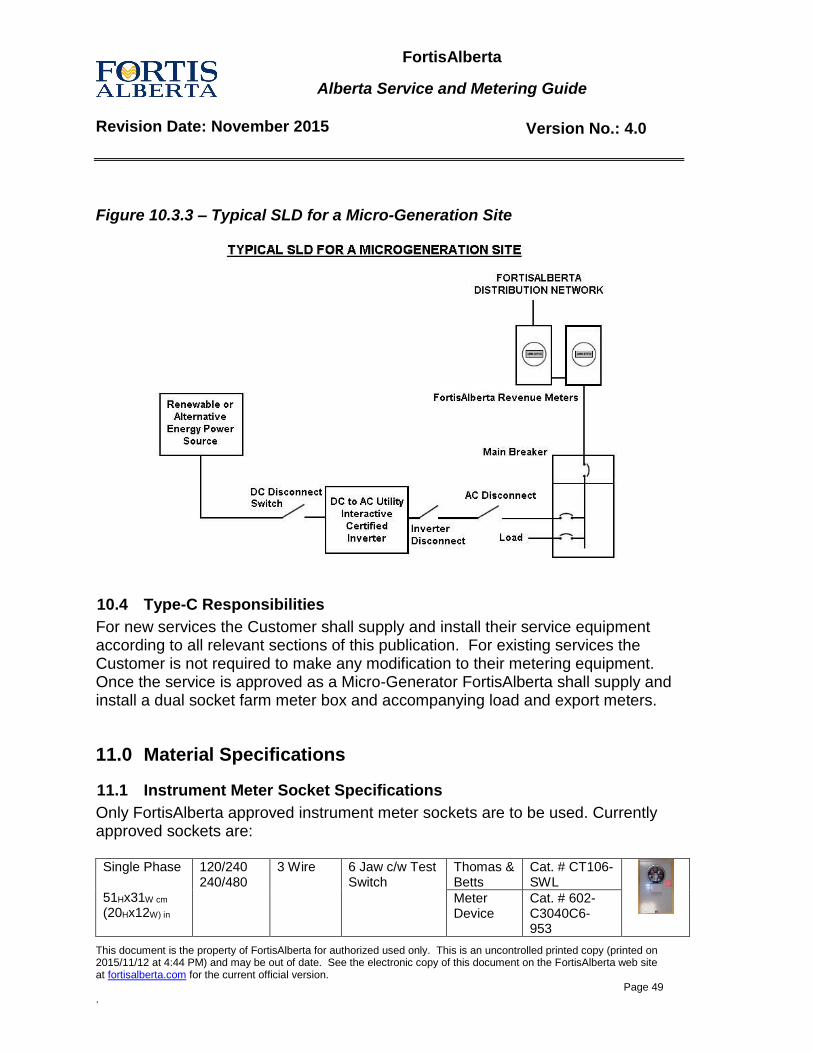
FortisAlberta
Alberta Service and Metering Guide
Revision Date: November 2015 Version No.: 4.0
This document is the property of FortisAlberta for authorized used only. This is an uncontrolled printed copy (printed on 2015/11/12 at 4:44 PM) and may be out of date. See the electronic copy of this document on the FortisAlberta web site at fortisalberta.com for the current official version.
Page 49 .
Figure 10.3.3 – Typical SLD for a Micro-Generation Site
10.4 Type-C Responsibilities
For new services the Customer shall supply and install their service equipment according to all relevant sections of this publication. For existing services the Customer is not required to make any modification to their metering equipment. Once the service is approved as a Micro-Generator FortisAlberta shall supply and install a dual socket farm meter box and accompanying load and export meters.
11.0 Material Specifications
11.1 Instrument Meter Socket Specifications
Only FortisAlberta approved instrument meter sockets are to be used. Currently approved sockets are:
Single Phase 51Hx31W cm
(20Hx12W) in
120/240 240/480
3 Wire 6 Jaw c/w Test Switch
Thomas & Betts
Cat. # CT106-SWL
Meter Device
Cat. # 602-C3040C6- 953
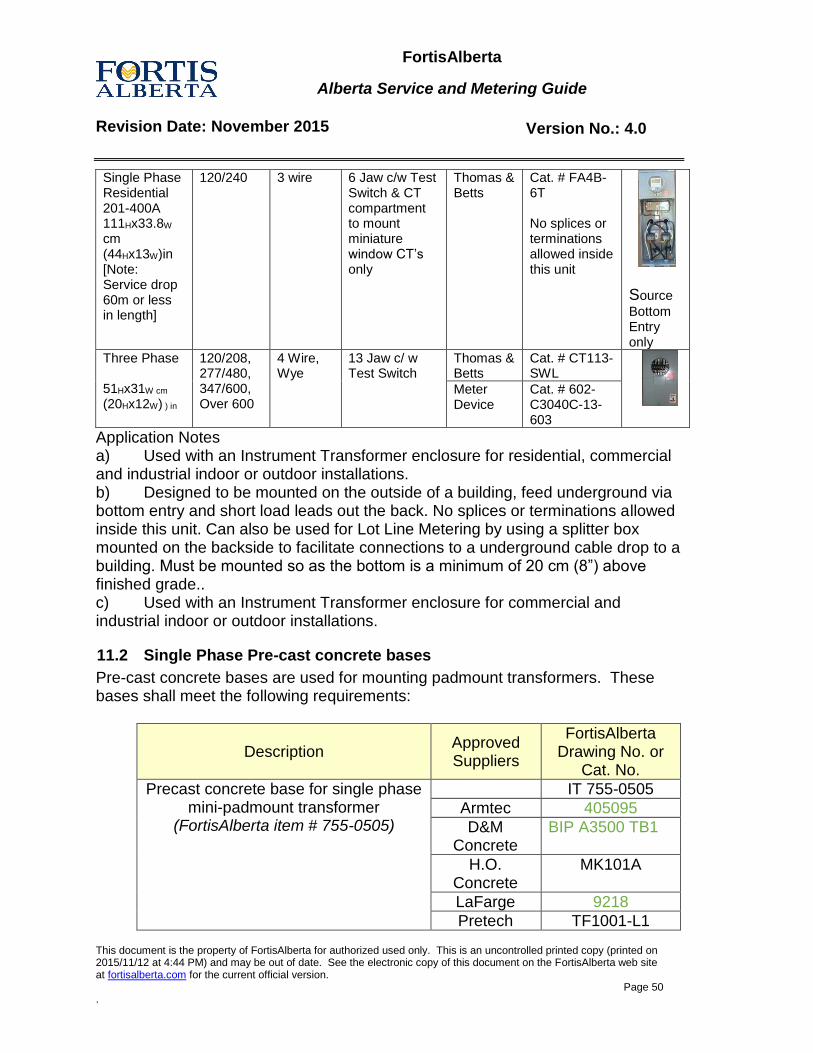
FortisAlberta
Alberta Service and Metering Guide
Revision Date: November 2015 Version No.: 4.0
This document is the property of FortisAlberta for authorized used only. This is an uncontrolled printed copy (printed on 2015/11/12 at 4:44 PM) and may be out of date. See the electronic copy of this document on the FortisAlberta web site at fortisalberta.com for the current official version.
Page 50 .
Single Phase Residential 201-400A 111Hx33.8W
cm
(44Hx13W)in [Note: Service drop 60m or less in length]
120/240 3 wire
6 Jaw c/w Test Switch & CT compartment to mount miniature window CT’s only
Thomas & Betts
Cat. # FA4B-6T No splices or terminations allowed inside this unit
Source
Bottom Entry only
Three Phase 51Hx31W cm
(20Hx12W) ) in
120/208, 277/480, 347/600, Over 600
4 Wire, Wye
13 Jaw c/ w Test Switch
Thomas & Betts
Cat. # CT113-SWL
Meter Device
Cat. # 602-C3040C-13-603
Application Notes a) Used with an Instrument Transformer enclosure for residential, commercial and industrial indoor or outdoor installations. b) Designed to be mounted on the outside of a building, feed underground via bottom entry and short load leads out the back. No splices or terminations allowed inside this unit. Can also be used for Lot Line Metering by using a splitter box mounted on the backside to facilitate connections to a underground cable drop to a building. Must be mounted so as the bottom is a minimum of 20 cm (8”) above finished grade.. c) Used with an Instrument Transformer enclosure for commercial and industrial indoor or outdoor installations.
11.2 Single Phase Pre-cast concrete bases
Pre-cast concrete bases are used for mounting padmount transformers. These bases shall meet the following requirements:
Description Approved Suppliers
FortisAlberta Drawing No. or
Cat. No.
Precast concrete base for single phase mini-padmount transformer
(FortisAlberta item # 755-0505)
IT 755-0505
Armtec 405095
D&M Concrete
BIP A3500 TB1
H.O. Concrete
MK101A
LaFarge 9218
Pretech TF1001-L1
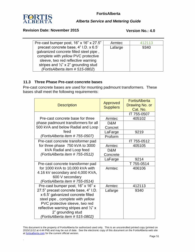
FortisAlberta
Alberta Service and Metering Guide
Revision Date: November 2015 Version No.: 4.0
This document is the property of FortisAlberta for authorized used only. This is an uncontrolled printed copy (printed on 2015/11/12 at 4:44 PM) and may be out of date. See the electronic copy of this document on the FortisAlberta web site at fortisalberta.com for the current official version.
Page 51 .
Pre-cast bumper post, 16” x 16” x 27.5” precast concrete base, 4” I.D. x 6.5’
galvanized concrete filled steel pipe , complete with yellow PVC protective
sleeve, two red reflective warning stripes and ½” x 2” grounding stud
(FortisAlberta item # 515-0802)
Armtec 412113
Lafarge
9340
11.3 Three Phase Pre-cast concrete bases
Pre-cast concrete bases are used for mounting padmount transformers. These bases shall meet the following requirements:
Description Approved Suppliers
FortisAlberta Drawing No. or
Cat. No.
Pre-cast concrete base for three
phase padmount transformers for all 500 kVA and below Radial and Loop
feed (FortisAlberta item # 755-0507)
IT 755-0507
Armtec 405102
D&M Concret
LaFarge 9219
Proform
Pre-cast concrete transformer pad for three phase 750 kVA to 3000
kVA Radial and Loop feed (FortisAlberta item # 755-0512)
IT 755-0512
Armtec 405105
D&M Concrete
LaFarge 9214
Pre-cast concrete transformer pad for 1000 kVA to 10,000 kVA with
4.16 kV secondary and 4,000 KVA, 600 V secondary
(FortisAlberta item # 755-0514)
T 755-0514
Armtec 406106
Pre-cast bumper post, 16” x 16” x 27.5” precast concrete base, 4” I.D.
x 6.5’ galvanized concrete filled steel pipe , complete with yellow PVC protective sleeve, two red
reflective warning stripes and ½” x 2” grounding stud
(FortisAlberta item # 515-0802)
Armtec 412113
Lafarge 9340
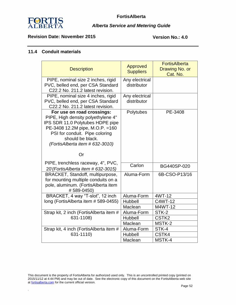
FortisAlberta
Alberta Service and Metering Guide
Revision Date: November 2015 Version No.: 4.0
This document is the property of FortisAlberta for authorized used only. This is an uncontrolled printed copy (printed on 2015/11/12 at 4:44 PM) and may be out of date. See the electronic copy of this document on the FortisAlberta web site at fortisalberta.com for the current official version.
Page 52 .
11.4 Conduit materials
Description Approved Suppliers
FortisAlberta Drawing No. or
Cat. No.
PIPE, nominal size 2 inches, rigid PVC, belled end, per CSA Standard
C22.2 No. 211.2 latest revision.
Any electrical distributor
PIPE, nominal size 4 inches, rigid PVC, belled end, per CSA Standard
C22.2 No. 211.2 latest revision.
Any electrical distributor
For use on road crossings: PIPE, High density polyethylene 4"
IPS SDR 11.0 Polytubes HDPE pipe PE-3408 12.2M pipe, M.O.P. =160
PSI for conduit. Pipe coloring should be black.
(FortisAlberta item # 632-3010)
Or
PIPE, trenchless raceway, 4", PVC,
20'(FortisAlberta item # 632-3015)
Polytubes
PE-3408
Carlon BG440SP-020
BRACKET, Standoff, multipurpose, for mounting multiple conduits on a pole, aluminum. (FortisAlberta item
# 589-0450)
Aluma-Form
6B-CSO-P13/16
BRACKET, 4 way “T-slot”, 12 inch long (FortisAlberta item # 589-0455)
Aluma-Form 4WT-12
Hubbell C4WT-12
Maclean M4WT-12
Strap kit, 2 inch (FortisAlberta item # 631-1108)
Aluma-Form STK-2
Hubbell CSTK2
Maclean MSTK-2
Strap kit, 4 inch (FortisAlberta item # 631-1110)
Aluma-Form STK-4
Hubbell CSTK4
Maclean MSTK-4
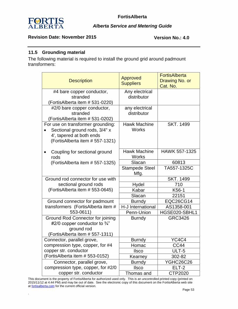
FortisAlberta
Alberta Service and Metering Guide
Revision Date: November 2015 Version No.: 4.0
This document is the property of FortisAlberta for authorized used only. This is an uncontrolled printed copy (printed on 2015/11/12 at 4:44 PM) and may be out of date. See the electronic copy of this document on the FortisAlberta web site at fortisalberta.com for the current official version.
Page 53 .
11.5 Grounding material
The following material is required to install the ground grid around padmount transformers:
Description Approved Suppliers
FortisAlberta Drawing No. or Cat. No.
#4 bare copper conductor, stranded
(FortisAlberta item # 531-0220)
Any electrical distributor
#2/0 bare copper conductor, stranded
(FortisAlberta item # 531-0202)
any electrical distributor
For use on transformer grounding:
Sectional ground rods, 3/4" x 4', tapered at both ends (FortisAlberta item # 557-1321)
Coupling for sectional ground rods (FortisAlberta item # 557-1325)
Hawk Machine Works
SKT. 1499
Hawk Machine Works
HAWK 557-1325
Slacan 60813
Stampede Steel Mfg.
TA557-1325C
Ground rod connector for use with sectional ground rods
(FortisAlberta item # 553-0645)
SKT. 1499
Hydel 710
Kabar K56-1
Slacan 22151
Ground connector for padmount transformers (FortisAlberta item #
553-0611)
Burndy EQC26CG14
H-J International AS1358-001
Penn-Union HGSE020-SBHL1
Ground Rod Connector for joining #2/0 copper conductor to ¾”
ground rod (FortisAlberta item # 557-1311)
Burndy GRC3426
Connector, parallel grove, compression type, copper, for #4 copper str. conductor (FortisAlberta item # 553-0152)
Burndy YC4C4
Homac CC44
Ilsco ULT-5
Kearney 302-82
Connector, parallel grove, compression type, copper, for #2/0
copper str. conductor
Burndy YGHC26C26
Ilsco ELT-2
Thomas and CTP2020
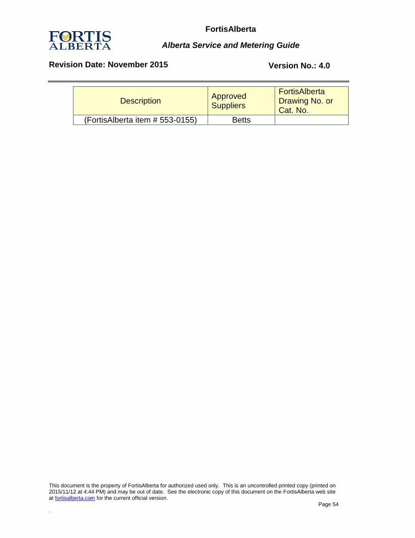
FortisAlberta
Alberta Service and Metering Guide
Revision Date: November 2015 Version No.: 4.0
This document is the property of FortisAlberta for authorized used only. This is an uncontrolled printed copy (printed on 2015/11/12 at 4:44 PM) and may be out of date. See the electronic copy of this document on the FortisAlberta web site at fortisalberta.com for the current official version.
Page 54 .
Description Approved Suppliers
FortisAlberta Drawing No. or Cat. No.
(FortisAlberta item # 553-0155) Betts
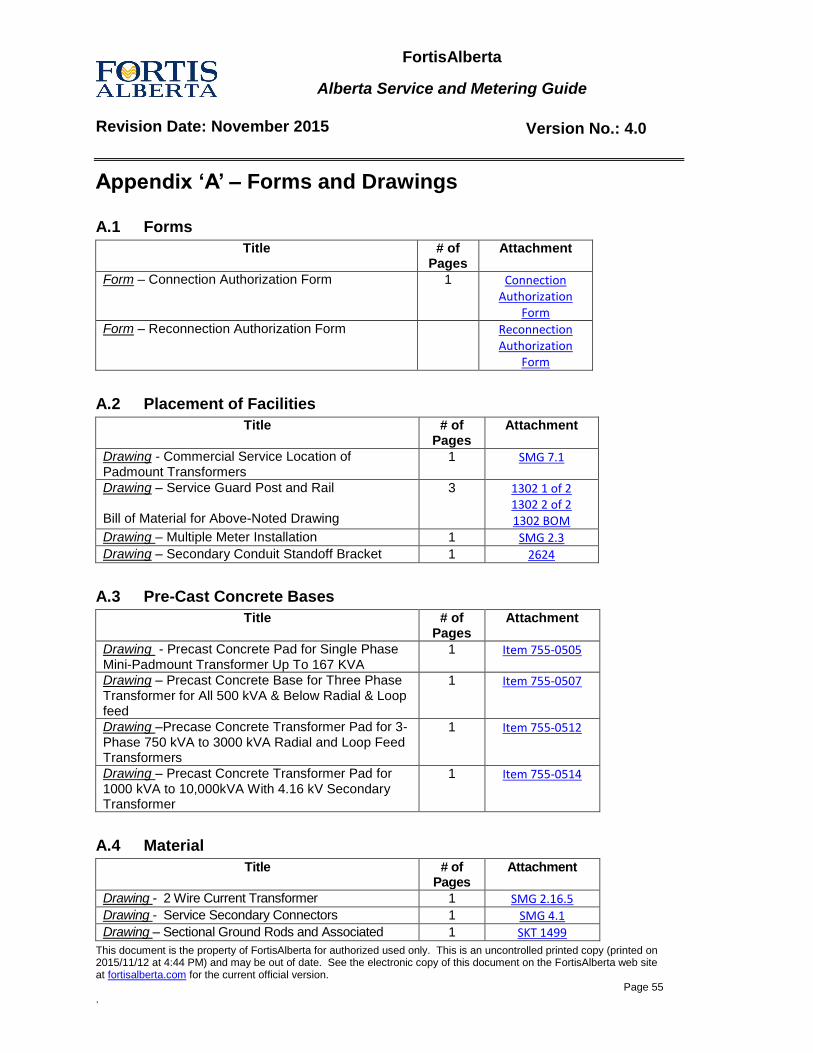
FortisAlberta
Alberta Service and Metering Guide
Revision Date: November 2015 Version No.: 4.0
This document is the property of FortisAlberta for authorized used only. This is an uncontrolled printed copy (printed on 2015/11/12 at 4:44 PM) and may be out of date. See the electronic copy of this document on the FortisAlberta web site at fortisalberta.com for the current official version.
Page 55 .
Appendix ‘A’ – Forms and Drawings
A.1 Forms
Title # of Pages
Attachment
Form – Connection Authorization Form 1 Connection Authorization
Form Form – Reconnection Authorization Form Reconnection
Authorization Form
A.2 Placement of Facilities
Title # of Pages
Attachment
Drawing - Commercial Service Location of Padmount Transformers
1 SMG 7.1
Drawing – Service Guard Post and Rail Bill of Material for Above-Noted Drawing
3
1302 1 of 2 1302 2 of 2 1302 BOM
Drawing – Multiple Meter Installation 1 SMG 2.3 Drawing – Secondary Conduit Standoff Bracket 1 2624
A.3 Pre-Cast Concrete Bases
Title # of Pages
Attachment
Drawing - Precast Concrete Pad for Single Phase Mini-Padmount Transformer Up To 167 KVA
1 Item 755-0505
Drawing – Precast Concrete Base for Three Phase Transformer for All 500 kVA & Below Radial & Loop feed
1 Item 755-0507
Drawing –Precase Concrete Transformer Pad for 3-Phase 750 kVA to 3000 kVA Radial and Loop Feed Transformers
1 Item 755-0512
Drawing – Precast Concrete Transformer Pad for 1000 kVA to 10,000kVA With 4.16 kV Secondary Transformer
1 Item 755-0514
A.4 Material
Title # of Pages
Attachment
Drawing - 2 Wire Current Transformer 1 SMG 2.16.5 Drawing - Service Secondary Connectors 1 SMG 4.1 Drawing – Sectional Ground Rods and Associated 1 SKT 1499
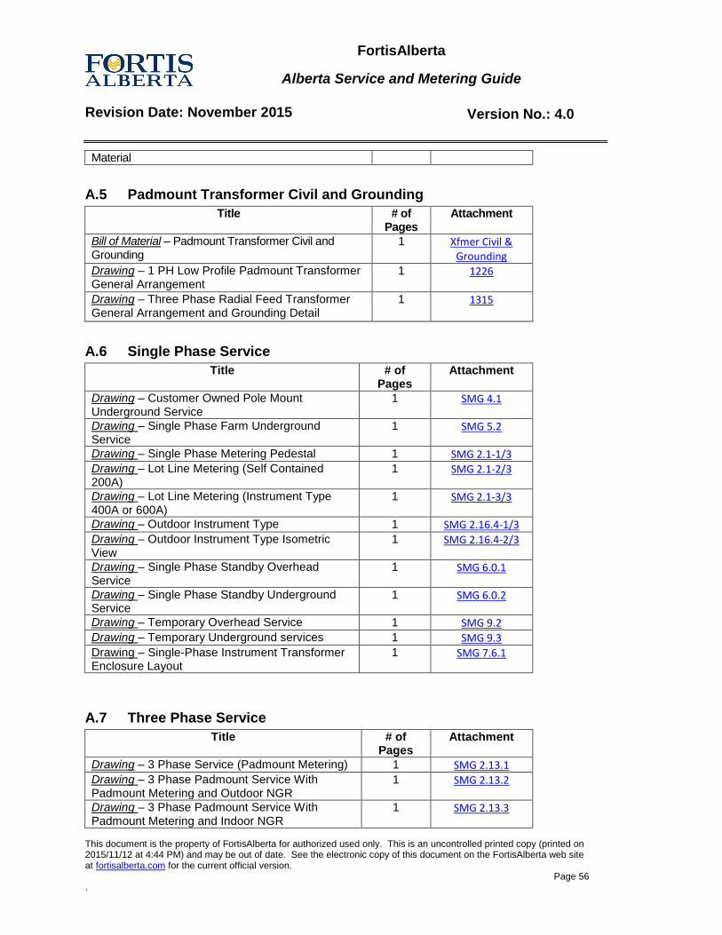
FortisAlberta
Alberta Service and Metering Guide
Revision Date: November 2015 Version No.: 4.0
This document is the property of FortisAlberta for authorized used only. This is an uncontrolled printed copy (printed on 2015/11/12 at 4:44 PM) and may be out of date. See the electronic copy of this document on the FortisAlberta web site at fortisalberta.com for the current official version.
Page 56 .
Material
A.5 Padmount Transformer Civil and Grounding
Title # of Pages
Attachment
Bill of Material – Padmount Transformer Civil and Grounding
1 Xfmer Civil & Grounding
Drawing – 1 PH Low Profile Padmount Transformer General Arrangement
1
1226
Drawing – Three Phase Radial Feed Transformer General Arrangement and Grounding Detail
1 1315
A.6 Single Phase Service
Title # of Pages
Attachment
Drawing – Customer Owned Pole Mount Underground Service
1 SMG 4.1
Drawing – Single Phase Farm Underground Service
1 SMG 5.2
Drawing – Single Phase Metering Pedestal 1 SMG 2.1-1/3 Drawing – Lot Line Metering (Self Contained 200A)
1 SMG 2.1-2/3
Drawing – Lot Line Metering (Instrument Type 400A or 600A)
1 SMG 2.1-3/3
Drawing – Outdoor Instrument Type 1 SMG 2.16.4-1/3 Drawing – Outdoor Instrument Type Isometric View
1 SMG 2.16.4-2/3
Drawing – Single Phase Standby Overhead Service
1 SMG 6.0.1
Drawing – Single Phase Standby Underground Service
1 SMG 6.0.2
Drawing – Temporary Overhead Service 1 SMG 9.2 Drawing – Temporary Underground services 1 SMG 9.3
Drawing – Single-Phase Instrument Transformer Enclosure Layout
1 SMG 7.6.1
A.7 Three Phase Service
Title # of Pages
Attachment
Drawing – 3 Phase Service (Padmount Metering) 1 SMG 2.13.1 Drawing – 3 Phase Padmount Service With Padmount Metering and Outdoor NGR
1 SMG 2.13.2
Drawing – 3 Phase Padmount Service With Padmount Metering and Indoor NGR
1 SMG 2.13.3
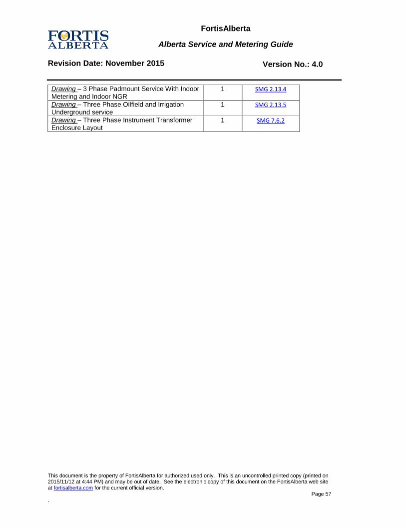
FortisAlberta
Alberta Service and Metering Guide
Revision Date: November 2015 Version No.: 4.0
This document is the property of FortisAlberta for authorized used only. This is an uncontrolled printed copy (printed on 2015/11/12 at 4:44 PM) and may be out of date. See the electronic copy of this document on the FortisAlberta web site at fortisalberta.com for the current official version.
Page 57 .
Drawing – 3 Phase Padmount Service With Indoor Metering and Indoor NGR
1 SMG 2.13.4
Drawing – Three Phase Oilfield and Irrigation Underground service
1 SMG 2.13.5
Drawing – Three Phase Instrument Transformer Enclosure Layout
1 SMG 7.6.2
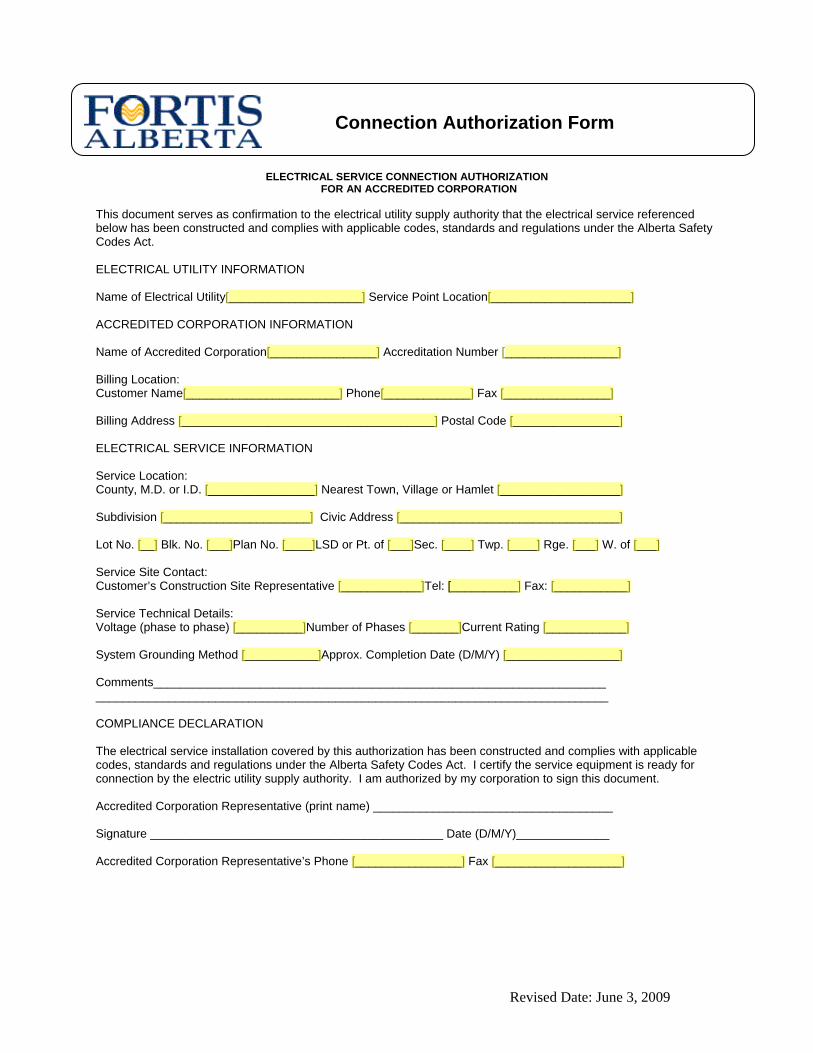
Connection Authorization Form
ELECTRICAL SERVICE CONNECTION AUTHORIZATION FOR AN ACCREDITED CORPORATION
This document serves as confirmation to the electrical utility supply authority that the electrical service referenced below has been constructed and complies with applicable codes, standards and regulations under the Alberta Safety Codes Act. ELECTRICAL UTILITY INFORMATION Name of Electrical Utility[____________________] Service Point Location[_____________________] ACCREDITED CORPORATION INFORMATION Name of Accredited Corporation[________________] Accreditation Number [_________________] Billing Location: Customer Name[_______________________] Phone[_____________] Fax [________________] Billing Address [______________________________________] Postal Code [________________] ELECTRICAL SERVICE INFORMATION Service Location: County, M.D. or I.D. [________________] Nearest Town, Village or Hamlet [__________________] Subdivision [______________________] Civic Address [_________________________________] Lot No. [__] Blk. No. [___]Plan No. [____]LSD or Pt. of [___]Sec. [____] Twp. [____] Rge. [___] W. of [___] Service Site Contact: Customer’s Construction Site Representative [____________]Tel: [__________] Fax: [___________] Service Technical Details: Voltage (phase to phase) [__________]Number of Phases [_______]Current Rating [____________] System Grounding Method [___________]Approx. Completion Date (D/M/Y) [_________________] Comments____________________________________________________________________ _____________________________________________________________________________ COMPLIANCE DECLARATION The electrical service installation covered by this authorization has been constructed and complies with applicable codes, standards and regulations under the Alberta Safety Codes Act. I certify the service equipment is ready for connection by the electric utility supply authority. I am authorized by my corporation to sign this document. Accredited Corporation Representative (print name) ____________________________________ Signature ____________________________________________ Date (D/M/Y)______________ Accredited Corporation Representative’s Phone [________________] Fax [___________________]
Revised Date: June 3, 2009
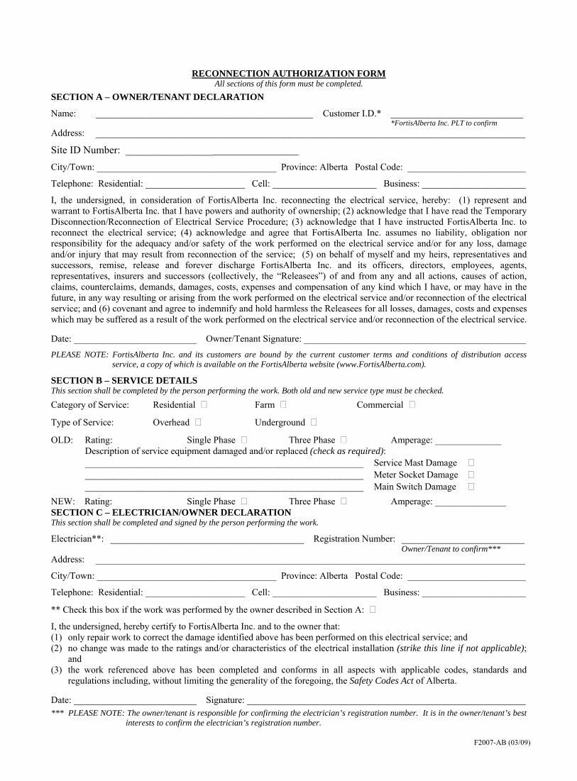
RECONNECTION AUTHORIZATION FORM All sections of this form must be completed.
SECTION A – OWNER/TENANT DECLARATION
Name: ______________________________________________ Customer I.D.* ____________________________ *FortisAlberta Inc. PLT to confirm
Address: ___________________________________________________________________________________________
Site ID Number: ___________________________________
City/Town: ______________________________________ Province: Alberta Postal Code: _________________________
Telephone: Residential: _____________________ Cell: ______________________ Business: ______________________
I, the undersigned, in consideration of FortisAlberta Inc. reconnecting the electrical service, hereby: (1) represent and warrant to FortisAlberta Inc. that I have powers and authority of ownership; (2) acknowledge that I have read the Temporary Disconnection/Reconnection of Electrical Service Procedure; (3) acknowledge that I have instructed FortisAlberta Inc. to reconnect the electrical service; (4) acknowledge and agree that FortisAlberta Inc. assumes no liability, obligation nor responsibility for the adequacy and/or safety of the work performed on the electrical service and/or for any loss, damage and/or injury that may result from reconnection of the service; (5) on behalf of myself and my heirs, representatives and successors, remise, release and forever discharge FortisAlberta Inc. and its officers, directors, employees, agents, representatives, insurers and successors (collectively, the “Releasees”) of and from any and all actions, causes of action, claims, counterclaims, demands, damages, costs, expenses and compensation of any kind which I have, or may have in the future, in any way resulting or arising from the work performed on the electrical service and/or reconnection of the electrical service; and (6) covenant and agree to indemnify and hold harmless the Releasees for all losses, damages, costs and expenses which may be suffered as a result of the work performed on the electrical service and/or reconnection of the electrical service.
Date: __________________________ Owner/Tenant Signature: _______________________________________________
PLEASE NOTE: FortisAlberta Inc. and its customers are bound by the current customer terms and conditions of distribution access service, a copy of which is available on the FortisAlberta website (www.FortisAlberta.com).
SECTION B – SERVICE DETAILS This section shall be completed by the person performing the work. Both old and new service type must be checked.
Category of Service: Residential Farm Commercial
Type of Service: Overhead Underground
OLD: Rating: Single Phase Three Phase Amperage: ______________ Description of service equipment damaged and/or replaced (check as required):
___________________________________________________________ Service Mast Damage ___________________________________________________________ Meter Socket Damage ___________________________________________________________ Main Switch Damage NEW: Rating: Single Phase Three Phase Amperage: _______________ SECTION C – ELECTRICIAN/OWNER DECLARATION This section shall be completed and signed by the person performing the work.
Electrician**: _________________________________________ Registration Number: __________________________ Owner/Tenant to confirm***
Address: ___________________________________________________________________________________________
City/Town: ______________________________________ Province: Alberta Postal Code: _________________________
Telephone: Residential: _____________________ Cell: ______________________ Business: ______________________
** Check this box if the work was performed by the owner described in Section A:
I, the undersigned, hereby certify to FortisAlberta Inc. and to the owner that: (1) only repair work to correct the damage identified above has been performed on this electrical service; and (2) no change was made to the ratings and/or characteristics of the electrical installation (strike this line if not applicable);
and (3) the work referenced above has been completed and conforms in all aspects with applicable codes, standards and
regulations including, without limiting the generality of the foregoing, the Safety Codes Act of Alberta.
Date: __________________________ Signature: ___________________________________________________________ *** PLEASE NOTE: The owner/tenant is responsible for confirming the electrician’s registration number. It is in the owner/tenant’s best
interests to confirm the electrician’s registration number.
F2007-AB (03/09)
Purpose: This procedure outlines the actions to be taken by owners and electrical contractors when performing planned or unplanned repair work on electrical services. Scope: This procedure applies to all owners and all electrical contractors, their employees and sub contractors when working on electrical services that are or will be supplied from FortisAlberta Inc. Electrical contractors are responsible for ensuring the information in this procedure is communicated to their employees and sub-contractors. Permit: A permit in the electrical discipline is required to install, alter or add to an electrical system. Some exceptions apply, as per the Safety Codes Act (Alberta), Permit Regulation, section 8(2). Definitions: In this procedure:
electrician means a person who holds a trade certificate or equivalent in the electrician trade acceptable under the Apprenticeship and Industry Training Act (Alberta);
owner includes a lessee, a person in charge, a person who has care and control and a person who holds out that the person has the powers and authority of ownership or who for the time being exercises the powers and authority of ownership;
permit issuer means a safety codes officer or a person designated to issue permits pursuant to section 44 of the Safety Codes Act (Alberta);
planned/unplanned work (no permit required) means electrical repair work on customer-owned equipment where the failed equipment must be repaired or replaced without modifying the ratings or characteristics of the electrical installation; and
planned/unplanned work (permit required) means electrical repair work on customer-owned equipment where the failed equipment must be replaced and modifies the ratings or characteristics of the electrical installation.
Procedures: All planned or unplanned work must be carried out by a qualified electrician or as required under article 9(1) of the Permit Regulation document AR 204/2007. It is in the owner’s best interests to confirm the electrician’s registration number. Disconnection of Service
The disconnection of service must be arranged with FortisAlberta Inc. by contacting 310 WIRE (i.e., 310 9743). An electrician may request FortisAlberta Inc.’s permission for such electrician to temporarily disconnect a customer’s
service for maintenance. FortisAlberta Inc. may, at its discretion, grant such permission if the electrician has: (1) identified the customer name and meter number of the service to be disconnected along with expected reconnection date and time; (2) confirmed that the electrician has been trained by FortisAlberta Inc. in the disconnection of electrical service; and (3) acknowledged that such disconnection by the electrician and maintenance by the electrician are at the electrician’s sole risk.
Reconnection of Service Reconnection of service must be arranged with FortisAlberta Inc. by contacting 310 WIRE (i.e., 310 9743). An electrician who disconnected the service by removing the meter, may re-install the same meter after receiving
prior approval from Fortis Alberta and installing a contractor meter seal. Should the disconnection be completed by the electrician at the weatherhead, Fortis Alberta MUST do the reconnection.
For planned/unplanned work on an electrical service where the ratings of the equipment has been modified and requires a permit, the permit must be provided to FortisAlberta Inc. prior to the reconnection.
Should it be impractical to obtain a permit (i.e., weekend, statutory holiday or after normal hours) for unplanned work, FortisAlberta Inc. may, at its discretion, reconnect without a permit. In this case, the owner and the electrician must sign a Reconnection Authorization Form releasing FortisAlberta Inc. from any and all liability for loss, damage or injury which may be suffered as a result of the reconnection.
When service is reconnected without a permit from an approved permit issuer, the electrician or owner must obtain a permit and forward same to FortisAlberta Inc. on the next business day where practical (otherwise, as soon as possible thereafter).
Failure to obtain a permit and forward same to FortisAlberta Inc. as noted above may result in customer notification and disconnection of service.
For planned/unplanned repair work on an electrical service where the ratings of the equipment has not been modified, and a permit is not required, FortisAlberta Inc. may, at its discretion, reconnect service without a permit if the owner and, if applicable, the electrician sign a Reconnection Authorization Form releasing FortisAlberta Inc. from any liability for loss, damage or injury which may be suffered as a result of the reconnection.
Prior to requesting a reconnect, the electrician or owner must ensure the main switch at the customer panel is placed in the open position, properly wired and enclosed.
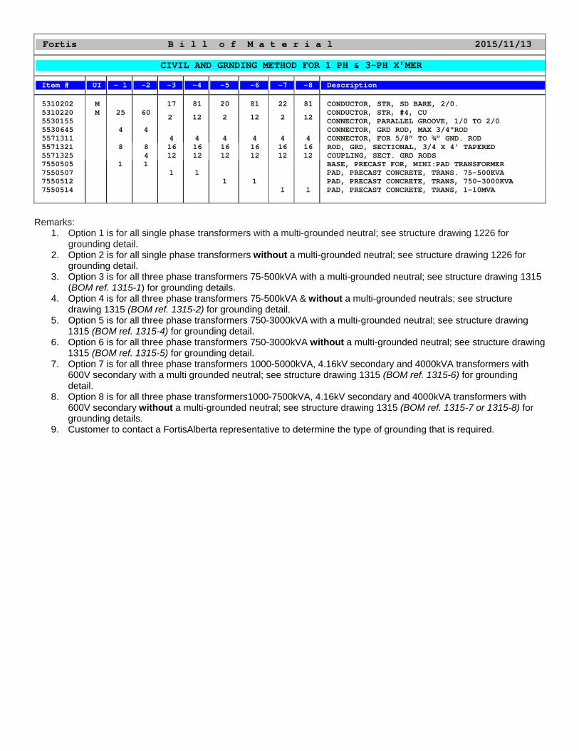
Fortis B i l l o f M a t e r i a l 2015/11/13
CIVIL AND GRNDING METHOD FOR 1 PH & 3-PH X’MER
Item # UI - 1 -2 -3 -4 -5 -6 -7 -8 Description
5310202 5310220 5530155
M M
25
60
17
2
81
12
20
2
81
12
22
2
81
12
CONDUCTOR, STR, SD BARE, 2/0. CONDUCTOR, STR, #4, CU CONNECTOR, PARALLEL GROOVE, 1/0 TO 2/0
5530645 5571311
4 4
4
4
4
4
4
4
CONNECTOR, GRD ROD, MAX 3/4"ROD CONNECTOR, FOR 5/8” TO ¾” GND. ROD
5571321 5571325
8 8 4
16 12
16 12
16 12
16 12
16 12
16 12
ROD, GRD, SECTIONAL, 3/4 X 4' TAPERED COUPLING, SECT. GRD RODS
7550505 7550507 7550512 7550514
1
1 1
1
1
1
1
1
BASE, PRECAST FOR, MINI:PAD TRANSFORMER PAD, PRECAST CONCRETE, TRANS. 75-500KVA PAD, PRECAST CONCRETE, TRANS, 750-3000KVA PAD, PRECAST CONCRETE, TRANS, 1-10MVA
Remarks:
1. Option 1 is for all single phase transformers with a multi-grounded neutral; see structure drawing 1226 for grounding detail.
2. Option 2 is for all single phase transformers without a multi-grounded neutral; see structure drawing 1226 for grounding detail.
3. Option 3 is for all three phase transformers 75-500kVA with a multi-grounded neutral; see structure drawing 1315 (BOM ref. 1315-1) for grounding details.
4. Option 4 is for all three phase transformers 75-500kVA & without a multi-grounded neutrals; see structure drawing 1315 (BOM ref. 1315-2) for grounding detail.
5. Option 5 is for all three phase transformers 750-3000kVA with a multi-grounded neutral; see structure drawing 1315 (BOM ref. 1315-4) for grounding detail.
6. Option 6 is for all three phase transformers 750-3000kVA without a multi-grounded neutral; see structure drawing 1315 (BOM ref. 1315-5) for grounding detail.
7. Option 7 is for all three phase transformers 1000-5000kVA, 4.16kV secondary and 4000kVA transformers with 600V secondary with a multi grounded neutral; see structure drawing 1315 (BOM ref. 1315-6) for grounding detail.
8. Option 8 is for all three phase transformers1000-7500kVA, 4.16kV secondary and 4000kVA transformers with 600V secondary without a multi-grounded neutral; see structure drawing 1315 (BOM ref. 1315-7 or 1315-8) for grounding details.
9. Customer to contact a FortisAlberta representative to determine the type of grounding that is required.
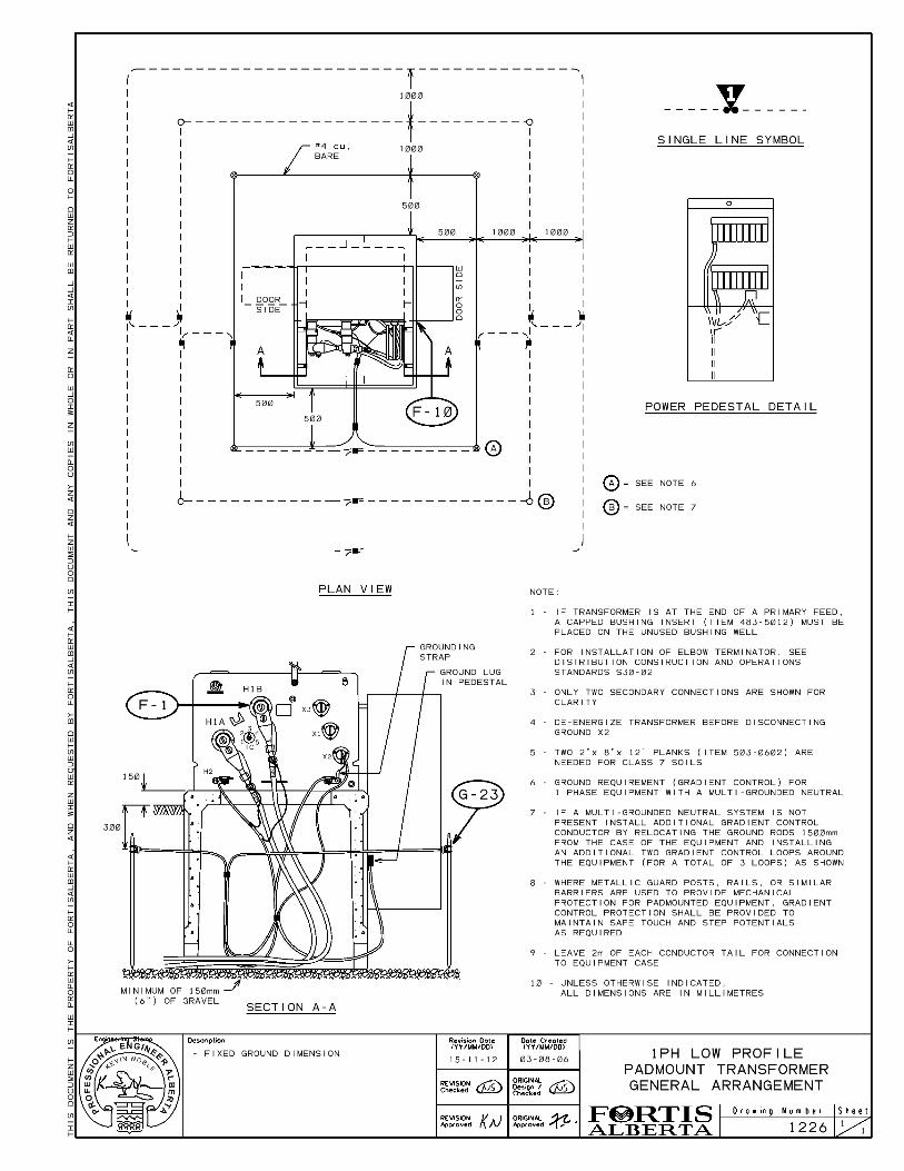
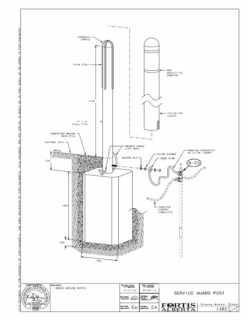
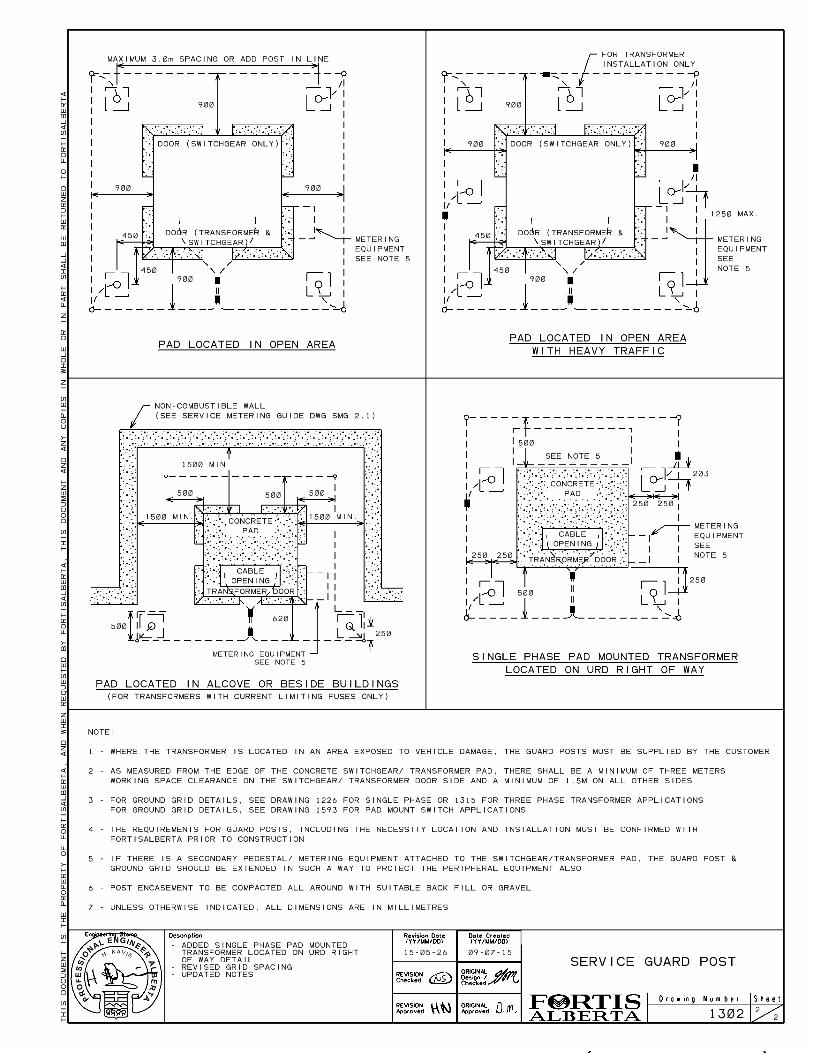

Structure #: 1302 FortisAlberta 2011/07/29 Page: 1 Description: SERVICE GUARD POST Item # Description UI -1 - - - - - - - - - 5141104 NUT, SQUARE, 1/2 INCH, UNC 13, GALV 2 5142102 WASHER, ROUND, 9/16" HOLE, 1-3/8" RIM 2 5150802 POST, BUMPER, HEAVY DUTY 1 5310220 CONDUCTOR, STR, #4, CU. M 1 5530645 CONNECTOR, GRD ROD, MAX 3/4"ROD 1
REMARKS: Bill of material is for one guard post only, order additional guard posts where required.