
CONTEXT CLUES CONTEXT CLUES Concept map WHAT ARE CONTEXT CLUES? Context Clues.
Upload
mervyn-powersCategory
view
217download
0
Formulation of Characteristic Equations for Instruments
P M V SubbaraoProfessor
Mechanical Engineering Department
Clues for Design of an Instrument to carry out Transient Measurements….

Characteristic Equation of A General Instrument
The characteristic equation of nth order system:
)(........... 012
21
1 txyaDyayDayDayDa nn
nn
)(....... 012
2
21
1
1 txyadt
dya
dt
yda
dt
yda
dt
yda
n
n
nn
n
n

Laplace Transformations for Instruments
sXsYasaasasas nn
nn
012
21
1 ...........
012
21
1 ...........
1
asaasasassX
sY
nn
nn
0
1 :
asX
sYOrderZero
01
1 :
asasX
sYOrderFirst
012
2
1 :
asaassX
sYOrderSecond

Generalized Instrument System : A combination of Blocks
The response analysis can be carried out to each independent block.

A True Instrument
• A true instrument should consist of only Zero-Order Blocks
• To investigate the response of a block, multiply its frequency domain form of characteristic equation with that of the chosen input equation.
• This is an interesting case because Equation shows that the zero-order block has no frequency dependent term, so the output for all given inputs can only be of the same time form as the input.
• What can be changed is the amplitude given as the coefficient a0.
• A shift in time (phase shift) of the output waveform with the input also does not occur.
• This is the response often desired in instruments because it means that the block does not alter the dynamics of input signal.
• The final destination of research in instrumentation is to find a true zero order instrument for every measurement.

Description of Turbulent Flow : Lessons from Nature
A Hurricane : THE VORTEX

Experimental Research in Turbulence
The Structure of Vortex
The vortical structures visualized by iso-surfaces of vorticity and Laplacianof pressure.
The size of energy-containing (largest) eddies may beEstimated as:
2
2
21
.
uul eddyenergetic
where, ω = ×u is the vorticity.∇
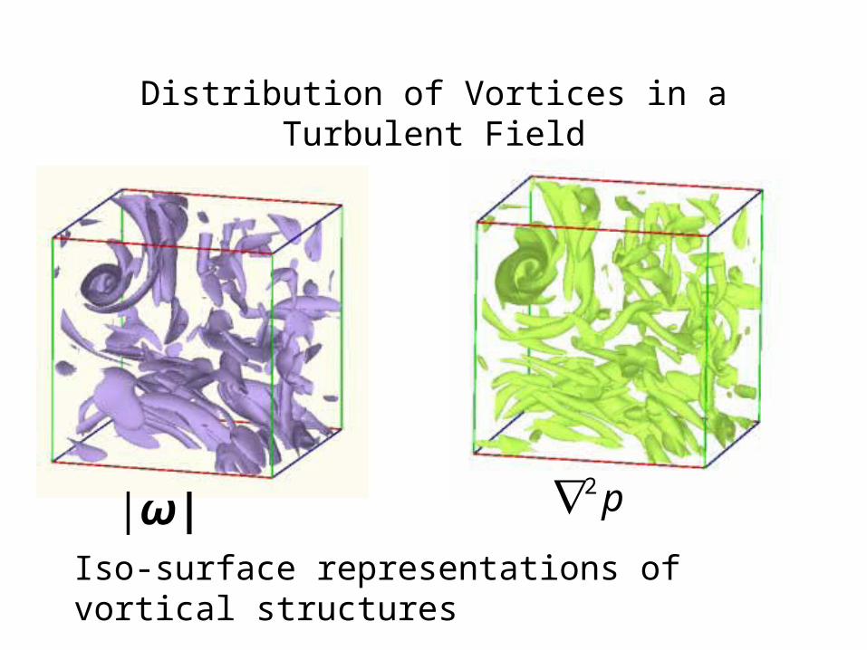
Distribution of Vortices in a Turbulent Field
Iso-surface representations of vortical structures
|ω| p2

True Structure of Turbulent Flow
1/size of vortex
Non
-dim
ensi
onal
Ene
rgy
of e
ddy
Only zero order probes can measure true Turbulence !!!

Zero Order Instrument: Wire Strain Gauge
:
ll
RR
KFactorGauge
This is the response often desired in instruments because it means that the block does not alter the time response. All instruments behave as zero order instruments when they give a static output in response to a static input.

Wire Strain Gauge

Wire Strain Gauge Pressure Transducers
In comparison with other types of pressure transducers, the strain gage type pressure transducer is of higher accuraciy, higher stability and of higher responsibility.The strain gage type pressure transducers are widely used as the high accuracy force detection means in the hydraulic testing machines.


TypeFeatures and
ApplicationsCapacity
RangeNonlinearity(%
RO)
Rated Output(m
V/V)
Compensated Temp.Range
( )℃
HVSHigh Accuracy
type0.5,..50 MPa 0.2,0.3 1.0,1.5±1 % - 10 to 60
HVUGeneral Purpose
type1,..50 MPa 0.3,0.5 1.5,2.0±1 % - 10 to 60
HVJSSmall & High
Temperature type
1,..50 MPa 0.5 1.0,1.5±20 % - 10 to 150
HVJS-JS
Small & High Temperature type,Vibratio
n-proof
1,..10 MPa 0.5 1.0,1.5±20 % - 10 to 150
Micro Sensor Technology Tokyo
First Order Instruments
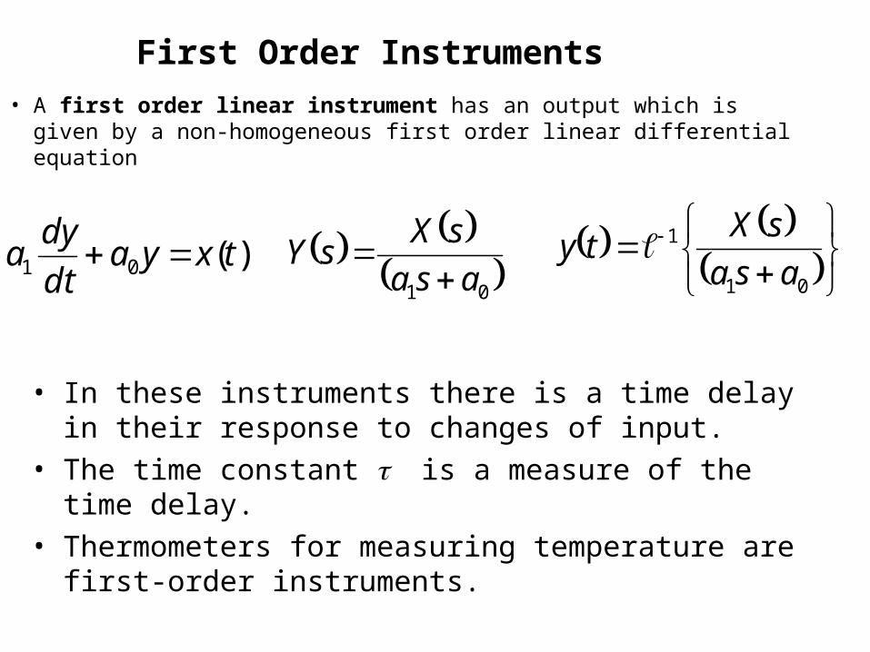
• A first order linear instrument has an output which is given by a non-homogeneous first order linear differential equation
)(01 txyadt
dya
01
asa
sXsY
01
1
asa
sXty
• In these instruments there is a time delay in their response to changes of input.
• The time constant is a measure of the time delay.
• Thermometers for measuring temperature are first-order instruments.

• The time constant of a measurement of temperature is determined by the thermal capacity of the thermometer and the thermal contact between the thermometer and the body whose temperature is being measured.
• A cup anemometer for measuring wind speed is also a first order instrument.
• The time constant depends on the anemometer's moment of inertia.

Development of Characteristic Equation
for Liquid–in –Glass Thermometer

Liquid in Glass Thermometer
TVV bulbT 1
bulbbulbbulb lrV 2
materialvolume
(10−6 K−1)alcohol, ethyl 1120gasoline 950jet fuel, kerosene 990mercury 181water, liquid (1 )℃ −50water, liquid (4 )℃ 0water, liquid (10 )℃ 88water, liquid (20 )℃ 207water, liquid (30 )℃ 303water, liquid (40 )℃ 385water, liquid (50 )℃ 457water, liquid (60 )℃ 522water, liquid (70 )℃ 582water, liquid (80 )℃ 640water, liquid (90 )℃ 695

Development of Characteristic Equation for a Thermometer
Conservation of Energy during a time dt
Heat in – heat out = Change in energy of thermometer
Assume no losses from the stem.
Heat in = Change in energy of thermometer
System theof eTemperatur ousInstantanetTs
tTs tTtf
fluid ric thermometof eTemperatur ousInstantanetTtf

Rs Rcond Rtf
Ts(t) Ttf(t)
tfconds RRRU
1
dtTTUAinheat tfsbulb
Change in energy of thermometer: tftfbulb dTCV
tftfbulbtfsbulb TCVdtTTUA
sbulbtfbulbtf
tfbulb TUATUAdt
dTCV

stftf
bulb
tfbulb TTdt
dT
UA
CV
bulb
tfbulb
UA
CV Define Time constant
stftf TT
dt
dT
s
Tsss s
tftf
s
Tss s
tf 1 1
ss
Ts s
tf
Step Response of Thermometers

1
s
T
s
Ts ss
tf
1
s
T
s
Ts ss
tf
1
11
ss
Ts stf
1
111
ss
TtT stf
t
TtT stf exp1
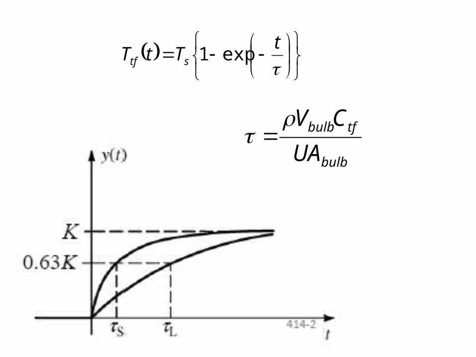
t
TtT stf exp1
bulb
tfbulb
UA
CV

Response of Thermometers: Periodic Loading
• If the input is a sine-wave, the output response is quite different;
• but again, it will be found that there is a general solution for all situations of this kind.
stftf
bulb
tfbulb TTdt
dT
UA
CV
22
max,max
s
stSinTT ssss

22
max,
ssss s
tftf
22
max,1
sss s
tf
122
max,
ss
s stf
122
max,1
sstT s
tf

t
tTe
TtT s
t
stf
1
22
max,
22max,
tan
sin11
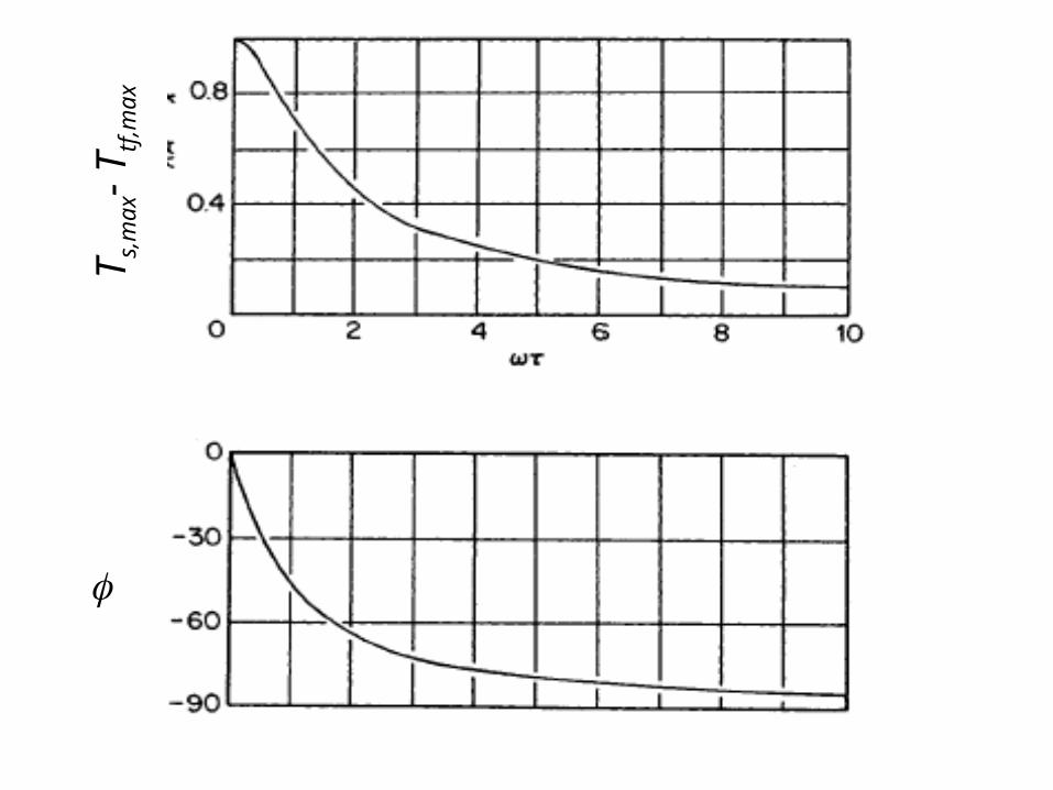
Ts,
max
- T
tf,m
ax