
Formation, modulation and adaptive twinning of martensite ... · 1 Formation, modulation and...
26
1 Formation, modulation and adaptive twinning of martensite in the Au 7 Cu 5 Al 4 shape memory system M.B. Cortie and F.C. Levey Mintek, Private Bag X3015, Randburg 2125, South Africa Abstract The Au 7 Cu 5 Al 4 electron phase transforms displacively from an L2 1 parent to a nominally body- centred tetragonal martensite with c/a<1. The compound is of interest because it has the potential to serve as an 18 carat shape memory alloy in jewellery. Analysis of its X-ray diffraction spectra indicates that the martensite is modulated by a [110]/[ 10 1 ] transverse shear wave, showing that it belongs, strictly speaking, to the generic B19 structure type. The martensite is also twinned, and the probable twinning structure is explored. A ) 6 , 9 ( 15R stacking sequence is deduced, which for reasons of the L2 1 ordering inherited from the parent phase, must be doubled to produce a notional ) 6 , 9 , 6 , 9 ( 30R martensite that properly repeats. However, although the measured X-ray diffraction spectra can be substantially explained by the structures derived, the martensite probably also has additional, higher-order lattice modulations. Keywords: martensite, shape memory alloy, X-ray diffraction, modulated structure, adaptive twining. corresponding author, fax : +27-11-709-4480, email : [email protected]
Transcript of Formation, modulation and adaptive twinning of martensite ... · 1 Formation, modulation and...
1
Formation, modulation and adaptive twinning of
martensite in the Au7Cu5Al4 shape memory system
M.B. Cortie and F.C. Levey
Mintek, Private Bag X3015, Randburg 2125, South Africa
Abstract
The Au7Cu5Al4 electron phase transforms displacively from an L21 parent to a nominally body-
centred tetragonal martensite with c/a<1. The compound is of interest because it has the potential to
serve as an 18 carat shape memory alloy in jewellery. Analysis of its X-ray diffraction spectra
indicates that the martensite is modulated by a [110]/[ 101 ] transverse shear wave, showing that it
belongs, strictly speaking, to the generic B19 structure type. The martensite is also twinned, and the
probable twinning structure is explored. A )6,9(15R stacking sequence is deduced, which for reasons
of the L21 ordering inherited from the parent phase, must be doubled to produce a notional
)6,9,6,9(30R martensite that properly repeats. However, although the measured X-ray diffraction
spectra can be substantially explained by the structures derived, the martensite probably also has
additional, higher-order lattice modulations.
Keywords: martensite, shape memory alloy, X-ray diffraction, modulated structure, adaptive twining.
corresponding author, fax : +27-11-709-4480, email : [email protected]

2
1. Introduction
The reversible displacive transformation in certain 18 carat Au-Cu-Al alloys has inspired their
application in jewellery, although details of the associated crystal structures and phase transformations
were not originally known [1]. Later it was shown that the addition of 5.8 wt.% Al to face-centred
cubic (Au,Cu) causes the structure at elevated temperatures to become body-centered cubic, with
lattice parameter a0.608 nm and electron-to-atom ratio e/a of 1.48 [2]. This ternary electron
compound has the approximate stoichiometry Au7Cu5Al4. It normally has strong B2 ordering, but
ageing at between 100 and 200°C causes the development of a variable amount of L21 ordering. Only
in this latter state does it undergo a martensitic transformation to a nominally body-centred tetragonal
(bct) martensite with a 16 atom unit cell and lattice parameters of a0.630 nm and c0.596 nm [3,4].
The martensite has c/a<1, which is an unusual situation since many martensites formed from body-
centred cubic (bcc) parents are approximately close-packed with hexagonal, orthorhombic or
monoclinic crystal structures, while most of the comparatively rare bct martensites that have been
recorded have c/a>1 [4]. The few example of bct martensites with c/a<1 known to the authors are
formed from La2AgIn, Ni2MnGa, AuMn and NiMn parent phases.
This paper addresses the structure of the Au7Cu5Al4 martensite, and shows that its atoms are slightly
displaced (‘modulated’ or ‘distorted’) from their nominal body-centred tetragonal lattice positions. The
nature of the lattice modulation necessary to explain its X-ray diffraction (XRD) spectrum and fine-
scale microstructure are explored.

3
2. Experimental
The procedures used to manufacture the alloy samples, characterise the phase transformations,
measure the XRD spectra, and determine the lattice occupancies of the parent phase have been
described elsewhere [2-4]. In brief, the samples were made by melting in a muffle furnace, and were
then subjected to heat treatments of various kinds, with the results of the heat treatments being
determined using optical metallography, acoustic emission and X-ray diffraction. The XRD spectra
shown here were obtained with Mo k radiation.
Modulation of the lattice of the martensite was investigated with the aid of a computer program that
ran within the Crystallographica
Pascal workspace. The program first constructed a unit cell with up
to 250 atoms and the desired occupancies, which were presumed to be inherited from the parent phase,
and then modulated it in terms of atomic position according to user dictates. The resulting structures
were then used to calculate XRD spectra, and these were compared to the experimental spectra.
3. Mechanism of tetragonal martensite formation
3.1 The bcc to tetragonal transformation
It is known that the martensitic transformation of a bcc electron phase is driven by the increasing
geometric instability of its lattice as the temperature decreases, and in particular by its tendency to
achieve a more negative free energy by collapsing to a denser packing arrangement [4,5]. This is
abetted in bcc parent lattices by their intrinsic geometric susceptibility to shear of the 011110 -
type [6,7]. This instability may also manifest in the form of a 011110 phonon soft mode. In the
most ideal case, a shear strain applied in the ]011[ direction along a (110) plane, accompanied by a
Crystallographica is a product of Oxford Cryosystems, 3 Blenheim Office Park, Lower Road, Long Hanborough, Oxford
OX8 8LN, UK.

4
lattice contraction in the perpendicular direction, will produce a fcc lattice from a bcc one [7]. Many of
the copper-based martensite structures are readily explained as being the result of such shear; however,
the actual structure produced contains a high density of regular stacking faults [7]. Although nominally
fcc, these faulted structures are more generally described as orthorhombic or monoclinic, depending on
how they are indexed.
However, shear on a single 011110 -type system cannot readily account for the formation of a
tetragonal martensite. This deficiency is remedied in the well-known phenomenological theory of
martensite crystallography (PTMC) which can account for a tetragonal martensite using a combination
of lattice deformation and macroscopic shape deformation. However, in yet another approach to the
same problem, an approximately tetragonal martensite can also be obtained from two shears, as in the
double shear mechanism of Bowles, Barret and Guttman, proposed 1950 [8]. In this mechanism, shear
took place sequentially along two 011110 systems, eg. first along 110101 to produce a
monoclinic structure and then along 011110 to produce a triclinic crystal that it is very nearly
tetragonal. Extending this principle, a perfectly tetragonal martensite, in this case with c/a<1, can be
conceptually produced from a cubic parent by the simultaneous application of four independent
011110 -type shears, provided that the principle of linear superposition can be applied. (In terms
of this principle, which is valid for Hookean elastic solids, the waves, shear or otherwise, can travel
through the solid quite independently of one another). The superposition of the shears will produce, by
vector addition, a net displacement of atomic co-ordinates that gives the product structure, without the
need to invoke an irrational shear system (Figure 1). If all four shear systems operate simultaneously,
and if the value of the shear strain () of each is equal, then the vector sum of all the displacement
components is as given in Table 1. It is evident that the z displacement is of opposite sign and twice
the magnitude of the x or y displacements. Once divided in each case by the starting cubic lattice
parameter, these become the lattice dilation/contraction strains, x, y, and z=-2x, a condition which

5
has been shown [9] to produce a habit plane between parent and martensite that is close to {011} and a
minimal change in the volume of the unit cell.
Application of a x of 2% to the cubic parent phase of Au7Cu5Al4 , which has a unit cell of ao=0.616
nm, will produce a martensite unit cell with a=b=0.628 nm, c=0.591 nm. Further adjustment to the
measured values [4] of a=b=0.630 nm, c=0.594 nm in the actual crystal (corresponding to x= 2.27%
and z= -3.57%) could conceivably take place in the lattice by thermally-induced relaxation, or the
deviation could be the result of some additional faulting or modulation in the structure.
It is recognised that the PTMC and the ‘two-’ and ‘four-shear’ mechanisms are not completely
compatible. In particular, the latter do not require, in principle, an interface between parent and
product phases, whereas the reaility is that the transformation takes place by means of the movement
of a well-defined interface between parent and product. Furthermore, there is the complication of
retaining a common plane (the ‘habit plane’) between parent and product phases during the
transformation. If the four-shear mechanism operates at all, it can only be in the immediate vicinity of
the habit plane. However, one advantage of the ‘four-shear’ explanation is that it invokes the known
lattive vibration modes to explain the atomic displacements, whereas the PTMC is silent on this issue.
Irrespective of its mechanism of formation, the normal, n, to the habit plane of the tetragonal
martensite can be calculated from the values of x and z, using the formula [9]
113311
11
113311
1133,,0
n (1)
where 11=x and 33=z. The result for the nominal values of x=2.0% and z=4.0% is the expected
(0 1 1) habit plane. However, substitution of the measured values of x and z for this transformation

6
give a normal vector with co-ordinates (0, 0.600, 0.797). This corresponds to a (0 3 4) habit plane, the
normal of which makes an angle of close to 8 to the normal to the (0 1 1) habit plane.
The X-ray diffraction spectrum calculated for a perfectly tetragonal martensite is compared in Figure 2
to some measured examples for this martensite. In general, there are small extra peaks on the
experimental martensite spectra. There were, in general, four prominent sets of extra peaks, denoted
‘a’ to ‘d’ on the Figure. It has been shown previously that these extra peaks may be reproduced if the
tetragonal symmetry of the martensite is reduced by either modifying the lattice occupancies or by
arbitrarily displacing certain of the atoms from their nominal positions [4]. However, the measured
martensite spectra were produced with a phase transformation that exhibited strong first-order
characteristics [3]. Therefore, a change in occupancy of the lattice sites during the transformation can
be eliminated, leaving positional modulation of the atoms as the probable cause.
3.2 The case for modulation
Modulation by a single shear wave
The 011110 phonon soft mode mentioned previously is often prominent in B2 structures as the
temperature of transformation to martensite is approached from above. However, it is important to note
that other lattice instabilities or combinations of lattice instabilities can operate prior to or during a
martensite transformation. Also, the soft mode phenomenon is not necessarily directly correlated with
martensitic transformation, and the presence of a vibrational soft mode does not guarantee that a
martensitic transformation will take place [5], nor are all martensitic transformations necessarily
driven by solely by soft mode phenomena [10]. Nevertheless, much of the atomic movement necessary
to produce, for example, a B19 martensite from a B2 parent, is very neatly explained as being the
result of the application of a [11 0]/[ 101 ] shear wave (the first term refers to the direction of
propagation k and the second to the polarization e of the transverse displacement wave) with a
7
wavelength of a2 , where a is the unit cell dimension of the parent B2 phase [11] (Figure 3). Of
course, some homogenous dilation and/or contraction of the lattice may also be required. The concept
of a soft mode shear wave therefore has some utility, at least in a pedagogic context, in explaining the
formation of hexagonal martensites from bcc parents.
The net effect of the application of the hypothetical shear wave is that the new atomic positions are
related to the old in two of the three lattice directions by a sinusoidal mathematical expression. In the
case of the B19 structure of AuCd, for example, it can be seen from Figure 3 that
iAk 2sin. (2)
where i is the fractional distance (varying from 0 to 1) along the B2 z-face diagonal (eventually the
aB19-axis) of the atom to be modulated, and k is the displacement from the nominal position in the
cB19-direction. The resulting crystal structure can therefore justly be considered to be a ‘modulated’
derivative of the original cubic parent structure, that is, its atomic positions are displaced from the
nominal starting lattice positions by some periodic oscillation.
If the parent has B2 ordering, then the modulated and parent structures can be shown to be both
members of the set of diverse close-packed B19 crystal structures. This follows because the basis
vectors of the generic B19 crystal structure are [12]
B1 = ¼aX + x1cZ
B2 = -¼aX - x1cZ
B3 = ¼aX + ½bY + x2cZ
B4 = -¼aX - ½bY - x2cZ (3)
8
where X, Y and Z are the principle axes, a, b and c are the B19 lattice parameters and x1 and x2 are
parameters that control the modulation of the atoms. Vectors B1 and B2 apply to the first element (eg.
Cd) and B3 and B4 to the second (eg. Au). Substitution of unit axes into the expressions generates the
atomic positions of the four atoms in the conventional representation of the B19 unit cell.
The usefulness of this generic structure can be seen by noting that, if a=b=c, x1=0.25, x2=x1+0.5, and
there is only one kind of element, then the structure is A1 (fcc). If a=c, x1=0.25, and x2=x1+0.5, then
the structure is L10. If 3
2
3
8
b
a, 21
3b
c,
65
1 x and 3
12 x and there is only one kind of
element then the structure is hexagonal close packed [12]. If a=c and 2b
athen the structure is B2,
or if there is only one kind of element, A2. Finally, it can be shown that the strongly modulated B19
structure of AuCd, for example, may be obtained from a B2 parent, by allowing ac, 2b
aand
increasing x1 to 0.31 [12].
Higher order modulation
In general, it seems that the structures of many martensites are modulated to a greater or lesser extent.
However, this modulation will rarely be as simple or complete as in the case of the B19 AuCd given
above. It has been claimed in some instances that this modulation is directly related to the soft mode
lattice instability that was associated with their formation [11,13]. In a widely used scheme, various
martensite structures are differentiated in terms of the number of basal planes corresponding to the
wavelength of the modulation or repetition. For example, the martensite formed from Ni0.64Al0.36 may
be denoted 7M (or 14M according to a different notation [14]) and it is formed by a modulation along
the [110] cubic direction with an effective wavelength of seven times the basal plane spacing [15].
Other structures with five, twelve or fifteen layers of basal planes have also been reported [14].
9
Of particular interest is that some investigators of the other tetragonal martensites have linked ‘extra’
X-ray diffraction peaks, such as those shown in Figure 2, to such positional modulations in the lattice.
Webster et al. [16], for example, who found such extra peaks in spectrum of the low temperature form
of Ni2MnGa, speculated that they were due to periodic stacking faults, lying perpendicular to the c-
axis direction of the bct lattice, and with a modulation of ‘at least four planes’. This point has been
investigated in more detail by later workers, who have elucidated the nature of these modulations in
this compound in some detail [14,17]. However, as mentioned, some of the ‘extra’ peaks can
potentially be generated by making non-symmetrical changes to lattice site occupancies. The present
authors also found that the introduction of regularly spaced anti-phase domain boundaries could result
in the generation of these and other extra peaks. However, since no independent evidence of such site
occupancy change or chemical modulation is so far known for this system, these lines of inquiry are
not pursued further here, and it is considered more likely that in this case the atomic positions of the
present Au7Cu5Al4 martensite were modulated, and that this might explain some or all of the ‘extra’
diffraction peaks.
The 011110 displacement in Ni2MnGa produces a ‘roughly’ tetragonal martensite with 5M
modulation (10M according to the notation used by Pons et al. [14]) parallel to the basal (001)M plane
or former (110) plane [15,17]. It is actually a two step process with a 3M modulated martensite in-
between [15]. It appears that accurate description of the modulation may require more than just a
single sinusoidal waveform, and for example in the case of Ni2MnGa the displacement of the
successive (110) planes (or (220) planes if they are indexed on the same 16 atom unit cell as the
parent Heusler phase) can be described by a three-term sinusoidal expansion [17]:
5
6sin.
5
4sin.
5
2sin.
lC
lB
lAl
(4)
10
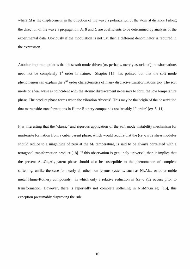
where l is the displacement in the direction of the wave’s polarization of the atom at distance l along
the direction of the wave’s propagation. A, B and C are coefficients to be determined by analysis of the
experimental data. Obviously if the modulation is not 5M then a different denominator is required in
the expression.
Another important point is that these soft mode-driven (or, perhaps, merely associated) transformations
need not be completely 1st order in nature. Shapiro [15] has pointed out that the soft mode
phenomenon can explain the 2nd
order characteristics of many displacive transformations too. The soft
mode or shear wave is coincident with the atomic displacement necessary to form the low temperature
phase. The product phase forms when the vibration ‘freezes’. This may be the origin of the observation
that martensitic transformations in Hume Rothery compounds are ‘weakly 1st order’ [eg. 5, 11].
It is interesting that the ‘classic’ and rigorous application of the soft mode instability mechanism for
martensite formation from a cubic parent phase, which would require that the (c11-c12)/2 shear modulus
should reduce to a magnitude of zero at the Ms temperature, is said to be always correlated with a
tetragonal transformation product [18]. If this observation is genuinely universal, then it implies that
the present Au7Cu5Al4 parent phase should also be susceptible to the phenomenon of complete
softening, unlike the case for nearly all other non-ferrous systems, such as NixAl1-x or other noble
metal Hume-Rothery compounds, in which only a relative reduction in (c11-c12)/2 occurs prior to
transformation. However, there is reportedly not complete softening in Ni2MnGa eg. [15], this
exception presumably disproving the rule.
11
4. Modulation of the Au7Cu5Al4 martensite lattice
4.1 Determination of the modulation wavelength
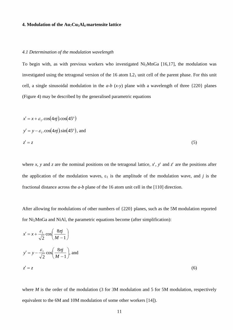
To begin with, as with previous workers who investigated Ni2MnGa [16,17], the modulation was
investigated using the tetragonal version of the 16 atom L21 unit cell of the parent phase. For this unit
cell, a single sinusoidal modulation in the a-b (x-y) plane with a wavelength of three {220} planes
(Figure 4) may be described by the generalised parametric equations
45cos.4cos.1 jxx
45sin.4cos.1 jyy , and
zz (5)
where x, y and z are the nominal positions on the tetragonal lattice, x, y and z are the positions after
the application of the modulation waves, 1 is the amplitude of the modulation wave, and j is the
fractional distance across the a-b plane of the 16 atom unit cell in the [110] direction.
After allowing for modulations of other numbers of {220} planes, such as the 5M modulation reported
for Ni2MnGa and NiAl, the parametric equations become (after simplification):
1
8cos
2
1
M
jxx
1
8cos
2
1
M
jyy
, and
zz (6)
where M is the order of the modulation (3 for 3M modulation and 5 for 5M modulation, respectively
equivalent to the 6M and 10M modulation of some other workers [14]).

12
Diffraction spectra were calculated for the present martensite using a 64 atom unit cell consisting of 4
16 atom tI16 unit cells in 2x2x1 configuration. For reasons of symmetry, this allowed only 3M, 5M
and 9M modulations to be tested, since the wavelength of the modulation had to divide into the z-face
diagonal of the unit cell by an integer factor, and also for it to be some integer multiple of the
wavelength of L21 atomic ordering in that direction. It was observed that the introduction of the
modulations enabled all the observed extra peaks to be explained, but undesired, extra peaks were
simultaneously introduced. In particular, the 3M modulations reproduced the peaks at positions b, c
and d in Figure 3, and the 5M modulation reproduced the peak at 0.237 nm (position e on Figure 4).
However, the 9M modulation scheme consistently produced a peak at 0.250 nm (position f on Figure
4), which was never observed on any experimental spectrum. The 5M scheme, however, had the
deficiency of not producing peaks c and d, and not one of these three schemes produced a peak at
position a. On balance, it was concluded that the 3M modulation system most generally simulated the
measured spectra. However, it was clear that a few samples possessed spectra with features like those
calculated for 5M modulation. These samples had in common the fact that they contained only
between 4 and 5 wt.% Al (compared to the usual 5.8 wt% Al of most other samples). Further work is
needed to verify this tentative correlation.
It should be noted that a simple one-term sinusoidal transverse wave may in practice be something of
an over-simplification, and in some cases investigators invoked higher harmonics of the basic wave
[17]. Similarly, there are other modulation wavelengths (eg. 4M, 6M, 7M etc) which the present
authors have not yet attempted. Therefore, the possibility that the spectra can be better explained as
being the outcome of something more complex than a 011110 shear wave with 3M or 5M
modulation wavelengths remains unexplored. Nevertheless, since the 3M scheme was able to account
for much of the observed detail in the diffraction spectra, it was selected for the next part of the
exercise, which was to determine the modulation amplitude.

13
4.2 Determination of the 3M (B19) modulation amplitude
It was shown earlier that the most general form of the B19 close-packed lattice requires five
parameters for description of atomic positions. The parameters are a, b and c (the B19 lattice
parameters), and x1 and x2, which control the displacement of the atoms off the unmodulated lattice
positions. However, the present martensite is formed from an L21 parent rather than from a B2 one, so
a full description of it requires a doubling of the B19 unit cell in the b direction, in order to account for
the additional, ternary, atomic ordering. Furthermore, as a simplification, we have set x2=x1+0.5, a
situation required by the geometry of the B19 unit cell [19]. The resulting atomic positions are listed in
Table 2, and the generic unit cell is illustrated in Figure 5. The site occupancies are presumed to be the
same as those previously estimated for the parent phase [2]
The a, b and c parameters of the new unit cell may be calculated from those of the 16 atom L21-
derived one by using the geometric relationships shown in Figure 3, which would give a=c=0.4455
nm, and b=0.594 nm. However, for greater accuracy, the analysis of the experimental XRD spectra
was repeated, this time in orthorhombic space, to produce a=0.4465 nm, b=0.594 nm and c=0.4435
nm. The lattice positions and occupancy data shown in Table 2 were then combined with these
dimensions, and x1 systematically varied to find the value of it that best fitted the observed average
heights of peaks b, c and d. The results (Figure 6) indicated that the difference between the measured
and calculated intensities of the peaks b, c and d is minimised at values of x1 that are respectively
0.288, 0.290 and 0.301. Of course, these values should be the same, illustrating the limitations of our
present experimental measurements. However, it can be stated that the value of x1 that best reproduces
the experimental spectra is 0.293 ±0.05, which is sufficient to show that the martensite is modulated
somewhat less than B19-AuCd.

14
5. Adaptive twinning
It has been shown above that the martensite is not perfectly tetragonal, and that it is both modulated
and very slightly orthorhombic. Nevertheless, from a geometric perspective, it is nominally tetragonal,
sufficiently so, we believe, to allow the application of the existing literature on cubic-to-tetragonal
transformations. For example, it has been shown that wedge-shaped laths occur in the present system,
a point believed to be uniquely diagnostic of cubic-to-tetragonal martensites [4,20].
The displacive transformation from a cubic to a tetragonal phase (and vice versa on heating), or from
one tetragonal variant to another, generates considerable strain in a macroscopic sample. However,
opposing this, there is also a requirement in these systems that the parent and product phases have a
coherent relationship across their mutual interfaces. The mismatch in lattice spacing between cubic and
tetragonal phases is reduced by them sharing a habit plane, which is common to both lattices, and in
some cases, by adaptive twinning or microtwinning of the martensite. The principles upon which the
microtwinning in tetragonal structured martensites are based have been elegantly stated by
Khachaturyan et al. [9]. They have shown how coherency can be achieved if the martensite forms
twins at the scale of a few lattice planes per twin variant. At this scale the twins are almost like
stacking faults or shuffles. These ‘adaptive martensites’ are likely to form if the surface energy of twin
boundaries is relatively low while the lattice mismatch between cubic parent and tetragonal product is
relatively high. The B19 AuCd martensite is known to be microtwinned, illustrating that, while not
strictly tetragonal, it too is susceptible to these same considerations.
In practice, adaptive martensite consists of a periodic alternation of two twin variants, of thickness d1
and d2 respectively. For these very fine-scale twins, d1=m.atw and d2=n.atw, where m and n are integers,
and atw is the interatomic spacing of the {110}B2 twinning planes. Of particular interest here is that
Khachaturyan et al. showed that there are special values of m and n that provide the minimum

15
interface misfit for a given combination of parent and product phase lattice parameters. If the volume
fraction of the variant with thickness d1 is , then it follows that
12
1
n
m
d
d (7)
For invariant plane strain
0
zx
x
(8)
where x=y, and these lattice strains are as defined earlier.
In the case of the present system, x=+2.27% and z=-3.57%, thereby indicating an of 0.389 for the
variant with thickness d1 or, quite equivalently, an of 0.611 for the other variant. A wide range of m
and n values can in principle meet the requirements of Equations (7) and (8). However, not all values
of m and n generate simple two-variant stacking sequences that correctly repeat at the second twin
boundary. Those that do are listed in Table 3 for m>=n, and these form the super-set out which the
selection must be made in the present exercise. The notation used for these martensites follows
Khachaturyan et al. [9]. The stacking sequences of two examples of two-variant adaptive martensite,
and one multiple variant adaptive martensite are shown in Figure 7, together with the corresponding
notation, to illustrate the system. All crystallographically valid structures must begin and end on the
same type of stacking fault, which, for example, makes some stacking schemes, such as )2,3(5R ,
impossible in terms of this notation. The )2,3(5R structure is however, simply a 5M modulated lattice
which could perhaps be approximately represented by the notation )2,2(52
1
2
1R . However, it is evident
16
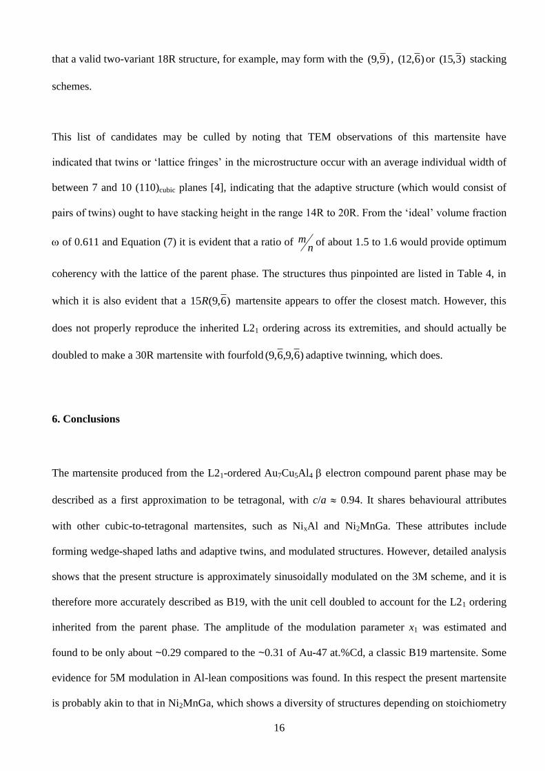
that a valid two-variant 18R structure, for example, may form with the )9,9( , )6,12( or )3,15( stacking
schemes.
This list of candidates may be culled by noting that TEM observations of this martensite have
indicated that twins or ‘lattice fringes’ in the microstructure occur with an average individual width of
between 7 and 10 (110)cubic planes [4], indicating that the adaptive structure (which would consist of
pairs of twins) ought to have stacking height in the range 14R to 20R. From the ‘ideal’ volume fraction
of 0.611 and Equation (7) it is evident that a ratio of n
m of about 1.5 to 1.6 would provide optimum
coherency with the lattice of the parent phase. The structures thus pinpointed are listed in Table 4, in
which it is also evident that a )6,9(15R martensite appears to offer the closest match. However, this
does not properly reproduce the inherited L21 ordering across its extremities, and should actually be
doubled to make a 30R martensite with fourfold )6,9,6,9( adaptive twinning, which does.
6. Conclusions
The martensite produced from the L21-ordered Au7Cu5Al4 electron compound parent phase may be
described as a first approximation to be tetragonal, with c/a 0.94. It shares behavioural attributes
with other cubic-to-tetragonal martensites, such as NixAl and Ni2MnGa. These attributes include
forming wedge-shaped laths and adaptive twins, and modulated structures. However, detailed analysis
shows that the present structure is approximately sinusoidally modulated on the 3M scheme, and it is
therefore more accurately described as B19, with the unit cell doubled to account for the L21 ordering
inherited from the parent phase. The amplitude of the modulation parameter x1 was estimated and
found to be only about ~0.29 compared to the ~0.31 of Au-47 at.%Cd, a classic B19 martensite. Some
evidence for 5M modulation in Al-lean compositions was found. In this respect the present martensite
is probably akin to that in Ni2MnGa, which shows a diversity of structures depending on stoichiometry

17
and thermal processing. Finally, the probable nature of the adaptive microtwinning was explored, and
it appears that a )6,9(15R stacking would provide optimum mimimisation of strain across the habit
plane. However, this does not correctly propagate the inherited L21 order, so a doubling of this
stacking scheme to )6,9,6,9(30R is actually required for symmetrical reasons. It is very unlikely,
however, that the martensite is perfectly stacked on this scheme, and it is therefore merely a
convenient approximation of what is probably a less regular defect structure.
Acknowledgements
This paper is published by permission of Mintek.
References
[1] Wolff IM, Cortie MB. Gold Bull. 1994; 27(2):44.
[2] Cortie MB, Levey FC. Intermetallics 2000; 8:793.
[3] Levey FC, Cortie MB, Cornish LA. Metall. Materials Trans. A 2000; 31A:1917.
[4] Levey FC, Cortie MB. Mater. Sci. Eng. A 2001; A303:1.
[5] Wasserman EF, Kästner J, Acet M, Entel P. In: Koiwa M et al, editor. Proc. Int. Conf. on Solid-
Solid Phase Transformations ’99, (JIMIC-3). Sendai, Japan : The Japan Institute of Metals, 1999.
p.807.
[6] Zener C. Phys. Rev. 1947; 71(12):846.
[7] Warlimont H, Delaey L. Progr. Mater. Sci. 1974; 18:1.
[8] Bowles JS, Barrett CS, Guttman L. J. Met., Trans. AIME 1950; 188:1478.
[9] Khachaturyan AG, Shapiro SM, Semenovskaya S. Phys. Rev. B 1991; 43(13): 10832.
[10] Krumhansl JA. J. de Physique IV, Colloque C2, supplement to J. de Physique III 1995; 5:3.
[11] Barsch GR, Ohba T, Hatch DM. Mater. Sci. Eng. A 1999; A273-275:161.

18
[12] Mehl, MJ. Naval Research Laboratory, USA, Internet site, http://cst-www.nrl.navy.mil /lattice
/struk/b19.html, accessed November 2000.
[13] Zheludev A, Shapiro SM, Wochner P, Schwartz A, Wall M, Tanner LE. J. de Physique IV,
Colloque C8 1995; 5: 1139.
[14] Pons J, Chernenko VA, Santamarta R, Cesari E. Acta Mater. 2000; 48:3027.
[15] Shapiro SM. In: Koiwa M et al, editor. Proc. Int. Conf. on Solid-Solid Phase Transformations ’99,
(JIMIC-3). Sendai, Japan : The Japan Institute of Metals, 1999. p.799.
[16] Webster PJ, Ziebeck KRA, Town SL, Peak MS. Philos. Mag. B, 1984; 49(3): 295.
[17] Martynov VV. J. de Physique IV, Colloque C8, supplement to J. de Physique III, 1995; 5:91.
[18] Khachaturyan AG. Theory of Structural Transformations in Solids, Wiley-Interscience, New
York, 1983.
[19] Dwight AE, Conner RA, Downey JW. Acta Cryst. 1965; 18:837.
[20] James RD, Hane KF. Acta Mater. 2000; 48:197.

19
FIGURE CAPTIONS
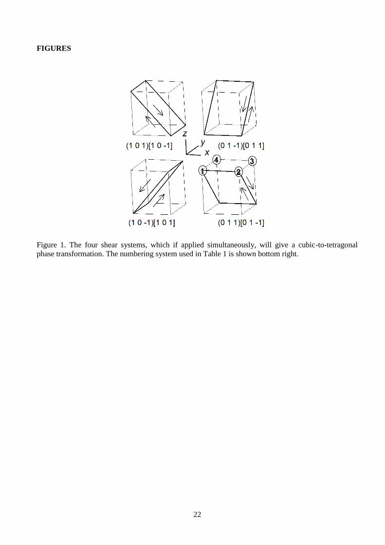
Figure 1. The four shear systems, which if applied simultaneously, will give a cubic-to-tetragonal
phase transformation. The numbering system used in Table 1 is shown bottom right.
Figure 2. Calculated X-ray spectrum of tetragonal martensite and examples of actual measured
martensite spectra.
Figure 3. Formation of B19 martensite from B2 parent by application of a [101]/[ 110 ] shear wave, a.
top view, b, rotated view. The atomic displacements that transform the B2 lattice into the B19 lattice
are omitted from the rotated view for clarity.
Figure 4. Calculated X-ray diffraction spectra for various modulation schemes. 3M spectrum computed
for 1=0.015 nm, 5M spectrum for 1=0.022 nm and 9M spectrum for 1=0.030 nm. Peaks at positions
b, c, d and e may be found on selected experimental spectra.
Figure 5. Doubly-extended B19 unit cell, as applied to the present martensite
Figure 6. Error in height of peaks b, c and d on spectra calculated for various 3M modulation
amplitudes, with respect to average peak height on five experimental spectra.
Figure 7. Stacking sequences of common 9R martensite, and those of hypothetical )1,4(5R and
)4,4(8R martensites, given here to illustrate the notation used. Dashed lines indicate the position of
notional stacking faults.

20
TABLES
Table 1. Atomic displacements x, y and z produced by four independent shear actions on atoms 1
to 4 in Figure 1, and their vector addition. (The displacements of the unnumbered atoms lying on the
lower face may be shown to be simply the reflection across the (002) plane of those on the upper face.)
Atom 1 Atom 2 Atom 3 Atom 4
]110[101 0, 0, 0 x, 0, -z +x, 0, -z 0, 0, 0
]011[101 0, -y, -z 0, -y, -z 0, 0, 0 0, 0, 0
]101[110 -x, 0, -z 0, 0, 0 0, 0, 0 -x, 0, -z
]101[011 0, 0, 0 0, 0, 0 0, y, -z 0, y, -z
Vector sum -x, -y, -2z +x, -y, -2z +x, +y, -2z -x, +y, -2z
Table 2. Cartesian positions and lattice occupancies of sites in the 3M unit cell of the present
martensite, derived by doubling of a generic B19 unit cell.
Site Nature x y z Occupancy
Au Cu Al
1 Au-rich ¼a 0 x1c 0.653 0.328 0.019
2 Au-rich -¼a 0 -x1c 0.653 0.328 0.019
3 Al-rich ¼a ¼b x2c 0.168 0.244 0.588
4 Cu-rich -¼a ¼b -x2c 0.267 0.388 0.345
5 Au-rich ¼a ½b x1c 0.653 0.328 0.019
6 Au-rich -¼a ½b -x1c 0.653 0.328 0.019
7 Cu-rich ¼a ¾b x2c 0.267 0.388 0.345
8 Al-rich -¼a ¾b -x2c 0.168 0.244 0.588

21
Table 3. Valid two-variant microtwinned adaptive martensites formed from a disordered cubic parent.
Only entries for m>=n are given, the entries for n<m may be derived by reflection.
m n
1 2 3 4 5 6 7 8 9 10 11 12
1 2R
2 4R
3 6R
4 5R 8R
5 7R 10R
6 9R 12R
7 8R 11R 14R
8 10R 13R 16R
9 12R 15R 18R
10 11R 14R 17R 20R
11 13R 16R 19R 22R
12 15R 18R 21R 24R
13 14R 17R 20R 23R
14 16R 19R 22R 25R
15 18R 21R 24R 27R
16 17R 20R 23R 26R
17 19R 22R 25R 28R
Table 4. Short-list of martensite structures with approximately correct twin width and lattice misfit
strain.
Structure n
m
)6,9(15R 1.50
)7,10(17R 1.43
)8,11(19R 1.38
)7,13(20R 1.86
22
FIGURES
Figure 1. The four shear systems, which if applied simultaneously, will give a cubic-to-tetragonal
phase transformation. The numbering system used in Table 1 is shown bottom right.

23
100
200
300
400
500
600
700
10 15 20 25 30 35
Two theta, °
Inte
ns
ity
calculated
measured 1
measured 2
measured 3
measured 4
measured 5
a b
b
b
b
b
c d
c d
c d
c
c d
Figure 2. Calculated X-ray spectrum of tetragonal martensite and examples of actual measured
martensite spectra.

24
a
-0.2
0
0.2
0.4
0.6
0.8
1
1.2
1.4
-1 -0.5 0 0.5 1 1.5
B2
B19
a
b
ac
b
-0.2
0
0.2
0.4
0.6
0.8
1
1.2
1.4
-1 -0.5 0 0.5 1 1.5
Figure 3. Formation of B19 martensite from B2 parent by application of a [101]/[ 110 ] shear wave, a.
top view, b, rotated view. The atomic displacements that transform the B2 lattice into the B19 lattice
are omitted from the rotated view for clarity.

25
290
340
390
440
490
540
590
640
690
10 15 20 25 30 35
Two theta, °
Inte
ns
ity
L10 tetragonal
3M modulated
5M modulated
9M modulated
b c d
e
f
Figure 4. Calculated X-ray diffraction spectra for various modulation schemes. 3M spectrum computed
for 1=0.015 nm, 5M spectrum for 1=0.022 nm and 9M spectrum for 1=0.030 nm. Peaks at positions
b, c, d and e may be found on selected experimental spectra.
Figure 5. Doubly-extended B19 unit cell, as applied to the present martensite

26
-15
-10
-5
0
5
10
15
20
25
30
0.24 0.26 0.28 0.30 0.32 0.34
Parameter x1
De
via
tio
n i
n p
ea
k h
eig
ht,
%
c
b
d
Figure 6. Error in height of peaks b, c and d on spectra calculated for various 3M modulation
amplitudes, with respect to average peak height on five experimental spectra.
-----A---- B --A------- A B ----C----- C -----A---- -----A---- A C ------B--- ------B--- ---B------ A A ----C----- C C B B B --A------- --A------- --A-------
9R )1,4(5R )4,4(8R
Figure 7. Stacking sequences of common 9R martensite, and those of hypothetical )1,4(5R and
)4,4(8R martensites, given here to illustrate the notation used. Dashed lines indicate the position of
notional stacking faults.


![Martensite Transformation In Sandvik Nanoflex · influence the martensite transformation [5]. Later on, the martensite fraction will be investigated that is why the martensite is](https://static.fdocuments.net/doc/165x107/5f10b9bc7e708231d44a845d/martensite-transformation-in-sandvik-influence-the-martensite-transformation-5.jpg)