Formal Veri cation of Surgical Robot Control...
60
Formal Verification of Surgical Robot Control Algorithm By Muhammad Saad Ayub 2011-NUST-MS-EE(S)-27 Supervisor Dr. Osman Hasan Department of Electrical Engineering A thesis submitted in partial fulfillment of the requirements for the degree of Masters in Electrical Engineering (MS EE) In School of Electrical Engineering and Computer Science, National University of Sciences and Technology (NUST), Islamabad, Pakistan. (July 2015)
Transcript of Formal Veri cation of Surgical Robot Control...

Formal Verification of Surgical RobotControl Algorithm
By
Muhammad Saad Ayub
2011-NUST-MS-EE(S)-27
Supervisor
Dr. Osman Hasan
Department of Electrical Engineering
A thesis submitted in partial fulfillment of the requirements for the degree
of Masters in Electrical Engineering (MS EE)
In
School of Electrical Engineering and Computer Science,
National University of Sciences and Technology (NUST),
Islamabad, Pakistan.
(July 2015)
Approval
It is certified that the contents and form of the thesis entitled “Formal
Verification of Surgical Robot Control Algorithm ” submitted by
Muhammad Saad Ayub have been found satisfactory for the requirement
of the degree.
Advisor: Dr. Osman Hasan
Signature:
Date:
Committee Member 1: Dr. Rehan Hafiz
Signature:
Date:
Committee Member 2: Dr. Amir Ali Khan
Signature:
Date:
Committee Member 3: Ms. Hira Taqdees
Signature:
Date:
i

Dedication
To My parents, Wife and Son
ii
Certificate of Originality
I hereby declare that this submission is my own work and to the best of my
knowledge it contains no materials previously published or written by another
person, nor material which to a substantial extent has been accepted for the
award of any degree or diploma at NUST SEECS or at any other educational
institute, except where due acknowledgement has been made in the thesis.
Any contribution made to the research by others, with whom I have worked
at NUST SEECS or elsewhere, is explicitly acknowledged in the thesis.
I also declare that the intellectual content of this thesis is the product
of my own work, except for the assistance from others in the project’s de-
sign and conception or in style, presentation and linguistics which has been
acknowledged.
Author Name: Muhammad Saad Ayub
Signature:
iii

Acknowledgment
I have been very fortunate to have Dr. Osman Hasan as my supervisor. I
am deeply grateful for his support throughout my research work.
I would also like to acknowledge the help of my wife for her encouragement
& invaluable moral support which helped me in stressful time.
I also wish to express my gratitude to Asad Hameed from SMART lab for
his support.
I also thank Dr. Rehan Hafiz, Dr. Muhammad Murtaza Khan, Dr. Amir
Ali Khan and Ms Hira Taqdees for their support. This journey would not
have been possible without the support of my parents. Thank you for
believing in me and wanting the best for me.
iv

Abstract
With the ever-growing interest in the usage of minimally-invasive surgery,
surgical robots are also being extensively used in the operation theaters.
Given the safety-critical nature of these surgeries, ensuring the accuracy and
safety of the control algorithms of these surgical robots is an absolute require-
ment. However, traditionally these algorithms have been analyzed using sim-
ulations and testing methods, which provide in-complete and approximate
analysis results due to their inherent sampling-based nature. We propose
to use probabilistic model checking, which is a formal verification method
for quantitative analysis of systems, to verify the control algorithms of sur-
gical robots in this thesis. As an illustrative example, the thesis provides
a formal analysis of a virtual fixture control algorithm, implemented in a
neuro-surgical robot, using the PRISM model checker. We have been able to
verify some probabilistic properties about the out-of-boundary problem for
the given algorithm and found some new insights, which were not gained in
a previous attempt of using formal methods in the same context. In order
to validate our verification results, we have also done some experiments by
running the considered algorithm on the Al-Zahrawi surgical robot.
v

Table of Contents
1 Introduction 1
1.1 Motivation . . . . . . . . . . . . . . . . . . . . . . . . . . . . . 1
1.2 Literature Review . . . . . . . . . . . . . . . . . . . . . . . . . 3
1.3 Thesis Contribution . . . . . . . . . . . . . . . . . . . . . . . . 6
1.4 Organization of Thesis . . . . . . . . . . . . . . . . . . . . . . 7
2 Preliminaries 8
2.1 Probabilistic Model Checking . . . . . . . . . . . . . . . . . . 8
2.2 PRISM Model Checker . . . . . . . . . . . . . . . . . . . . . . 10
2.3 A Virtual Fixture Control Algorithm for Surgical Robots: . . . 11
3 Proposed Methodology 14
3.1 Modeling Control Algorithm in PRISM . . . . . . . . . . . . . 14
3.2 Functional Verification using Simulation . . . . . . . . . . . . 15
3.3 Formal Function Verification . . . . . . . . . . . . . . . . . . . 16
4 Modeling the virtual fixture algorithm in PRISM 18
4.1 Force Module . . . . . . . . . . . . . . . . . . . . . . . . . . . 19
4.2 Velocity Module . . . . . . . . . . . . . . . . . . . . . . . . . . 20
4.3 Position Module . . . . . . . . . . . . . . . . . . . . . . . . . . 21
4.4 Model For Multiple Surgical Tools . . . . . . . . . . . . . . . . 22
vi

TABLE OF CONTENTS vii
5 Verification 25
5.1 Deadlock Freedom . . . . . . . . . . . . . . . . . . . . . . . . 25
5.2 Reachability . . . . . . . . . . . . . . . . . . . . . . . . . . . . 26
5.3 Out of Boundary . . . . . . . . . . . . . . . . . . . . . . . . . 28
5.4 Collision Freeness . . . . . . . . . . . . . . . . . . . . . . . . . 31
6 Testing on Al-Zahrawi 37
6.1 Experimental Setup . . . . . . . . . . . . . . . . . . . . . . . . 39
6.2 Experiment Procedure . . . . . . . . . . . . . . . . . . . . . . 40
6.3 Results . . . . . . . . . . . . . . . . . . . . . . . . . . . . . . . 41
7 Conclusion and Future Work 43
7.1 Conclusion . . . . . . . . . . . . . . . . . . . . . . . . . . . . . 43
7.2 Future Work . . . . . . . . . . . . . . . . . . . . . . . . . . . . 44

List of Figures
2.1 Markovian models . . . . . . . . . . . . . . . . . . . . . . . 9
3.1 Proposed methodology . . . . . . . . . . . . . . . . . . . . 16
4.1 virtual fixture zones . . . . . . . . . . . . . . . . . . . . . . 19
5.1 Reachability rewards vs width of slow zone . . . . . . . 27
5.2 Reachability rewards vs width of slow zone for differ-
ent max force . . . . . . . . . . . . . . . . . . . . . . . . . . 28
5.3 Effects of the Slow zone width on Probability of Failures 31
5.4 Position of the tool(Dx=20,Dy=17,Fmax=6,Fmin=-6) 32
5.5 Effect of Force on Probability of Collision on initial
model . . . . . . . . . . . . . . . . . . . . . . . . . . . . . . . 34
5.6 Effect of Force on Probability of Collision on model
with obstacle module . . . . . . . . . . . . . . . . . . . . . 34
5.7 Effect of Force on Probability of Collision for both
models . . . . . . . . . . . . . . . . . . . . . . . . . . . . . . 35
5.8 Effect of Force on Probability of Collision for different
widths of slow zone . . . . . . . . . . . . . . . . . . . . . . 36
6.1 System Level Architecture of Al-Zahrawi . . . . . . . . 38
6.2 Master Manipulator . . . . . . . . . . . . . . . . . . . . . . 38
viii

LIST OF FIGURES ix
6.3 Slave Manipulator . . . . . . . . . . . . . . . . . . . . . . . 39
6.4 Testbed for the experiment . . . . . . . . . . . . . . . . . 40
6.5 Test Procedure . . . . . . . . . . . . . . . . . . . . . . . . . 41
6.6 Experimental Results . . . . . . . . . . . . . . . . . . . . . 42

Chapter 1
Introduction
Surgical Robots are replacing conventional surgical operations throughout
the world. This thesis aims to ensure functional and behavioral correctness of
the control algorithm present in these surgical robots, thus formal verification
is used for verification instead of simulation. Probabilistic model checking of
the algorithm implemented in the surgical robot is performed.
1.1 Motivation
The emerging robotic technology is bridging the digital physical divide gap
and is thus revolutionizing the human lives in many ways. Wether it is a do-
mestic field or a commercial application, these customized electro-mechanical
machines usually handle the task more efficiently than humans. These days
robots are being widely used to perform most of the highly specific, extremely
precise, and safety-critical tasks in our everyday life, such as exploring the
deep sea [24], diffusion of bombs and mines [20], exploring shipwrecks [3] and
most importantly in the field of medicine [7][34].
One of the most wide-spread usage of robotic technology in the field of
1

CHAPTER 1. INTRODUCTION 2
medicine has been observed in minimal-invasive surgery (MIS) [25], i.e, a
surgical procedure in which a laparoscope (a thin lighted tube), along with a
high resolution camera [19], and other surgical instruments are inserted into
the human body through small incisions rather than a relatively larger inci-
sion commonly used in the traditional open surgeries. The internal operating
field may then be visualized on a video monitor connected to the scope. MIS
has become quite popular these days as it facilitates quick patient recovery
and less chance of post-operative infections. However, these added benefits
come at the cost of highly precise movements required by the surgeons in
the confined space provided. Robotic arms and hands have a high degree of
dexterity, allowing surgeons the ability to operate in these very tight spaces
in the body that would otherwise only be accessible through open (long inci-
sion) surgery. Operations relevant to microanatomy and neuroendoscopy are
performed through MIS because of the static nature of human skull. More-
over treating the brain tumor via small hole surgery also reduces the risk of
damaging the brain tissue overlying the tumor. All these above-mentioned
minimum invasive surgeries are now performed with the aid of surgical robots.
Despite the extreme precision of surgical robots, these man made ma-
chines bring in their own inaccuracies with them. There is always a risk that
these robotic arms may go out of control and damage other organs instead
of working in the surgical area. This problem is termed as out-of-boundry
problem. As these robots are operated by humans via a software interface.
Thus, the substantial loss of force feedback (haptics) and a lack of adapt-
ability are the most common risk factors that lead to the out-of-boundary
problem [7]. These problems may lead to life threatening situations, due to
the safety-critical nature of human surgeries [31].
In order to cater for the out-of-boundary problems, the conventional ap-
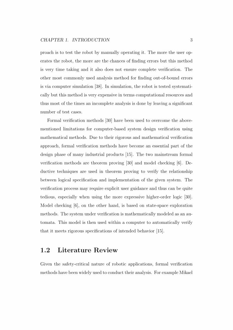
CHAPTER 1. INTRODUCTION 3
proach is to test the robot by manually operating it. The more the user op-
erates the robot, the more are the chances of finding errors but this method
is very time taking and it also does not ensure complete verification. The
other most commonly used analysis method for finding out-of-bound errors
is via computer simulation [38]. In simulation, the robot is tested systemati-
cally but this method is very expensive in terms computational resources and
thus most of the times an incomplete analysis is done by leaving a significant
number of test cases.
Formal verification methods [30] have been used to overcome the above-
mentioned limitations for computer-based system design verification using
mathematical methods. Due to their rigorous and mathematical verification
approach, formal verification methods have become an essential part of the
design phase of many industrial products [15]. The two mainstream formal
verification methods are theorem proving [30] and model checking [6]. De-
ductive techniques are used in theorem proving to verify the relationship
between logical specification and implementation of the given system. The
verification process may require explicit user guidance and thus can be quite
tedious, especially when using the more expressive higher-order logic [30].
Model checking [6], on the other hand, is based on state-space exploration
methods. The system under verification is mathematically modeled as an au-
tomata. This model is then used within a computer to automatically verify
that it meets rigorous specifications of intended behavior [15].
1.2 Literature Review
Given the safety-critical nature of robotic applications, formal verification
methods have been widely used to conduct their analysis. For example Mikael

CHAPTER 1. INTRODUCTION 4
[23] performed the probabilistic model checking of the behavior of swarm
robots. He targeted the flexibility property of swarm robots and validated
this approach on a collective foraging scenario. Kim et al. [26] developed the
discrete control software of the Samsung’s home robot (SHR) using Esterel
and perfomed model checking by using the xeve model checker to verify
the stopping behavior of SHR. Webster et al. [29] verified the autonomous
decision making system of a personal home robot using the SPIN model
checker. Schere et al. [33] built a method for the verification of robotic
control software based on the Java path finder. They verified the safety and
liveness properties for a line following robot.
Model checking has also been used to verify the motion planning algo-
rithms of various robots [28][14]. Lahijanian et al. [28] found the probability
of the robot reaching its destination via a safe path. Similarly, Fainekos et al.
[14] addressed the problem of generating continuous trajectories for mobile
robots while satisfying formulas in temporal logic using the NuSMV model
checker. The most recent work on the formal verification of path planning
algorithms is done by Saberi at al [1], who have worked on verifying that
the behavior of multi-robotic systems exhibit desired properties for optimal
operation. They used the mCRL2 language [18] to create a formal model for
a multi-robot system by creating different communicating processes and the
Modal u-calculus[16] to specify the desired properties of verification. The
robot workspace is assumed to be a grid that is equally divided into two
dimensional cells, whereas only one robot can occupy a single cell at a time.
They verified three important properties in context of path planning, i.e.,
Deadlock Freedom to check that any robot will not get stuck in a particular
cell, Collision-freeness to check that the robots in the model will not collide
with each other in any case and the Reachability property to ensure that the

CHAPTER 1. INTRODUCTION 5
robot will reach its desired destination within a finite number of steps.
Li [21] used the HOL4 theorem prover to verify the collision freeness
property for collision-free motion planning algorithm (CFMC) of a dual-arm
robot. Both the arms of the robot work simultaneously and the major risk in
their operation is the collision of both arms with each other.The objective of
the verification was to verify that the robotic arms follow an optimum path
from the source to the destination without colliding. The original algorithm
was found to have a semantic inconsistency and was modified to improve the
search efficiency and planning. The revised algorithm was re-verified and
proved to be collision-free.
On the other hand, the formal verification of surgical robots has been
barely touched. The main reasons of this gap include the complex dynam-
ics and uncertainties involved in these physical systems, which makes their
formal verification task quite challenging. Bresolin at al [9] used hybrid au-
tomata [36] to formalize an autonomous surgical robot and analyzed the
surgical task of puncturing i.e., the method of piercing a biological tissue
with the help of a needle. The sequence task required in the particular pro-
cedure were broken down in sub tasks and the workspace was partitioned
into boundaries considering safe and dangerous regions. Two properties are
then verified: The force of puncturing needle applied to the patient should
always be less than a particular threshold and the position of puncturing
needle should always remain within the target region.
It was found that many simple assumptions taken during the procedure
can result in large errors. The model was accordingly refined to cater for
these assumptions using a new semantic of hybrid automata, i.e., As-Soon-
As-Possible(AASAP) [10] and was verified to be better than the previous
abstraction.

CHAPTER 1. INTRODUCTION 6
Recently, a formal modeling and verification approach for the virtual fix-
ture control algorithm for a surgical robot has been reported in [38]. The
authors used a hybrid logic, i.e., differential dynamic logic and quantified
differential dynamic logic to model the system and verify it using the Key-
maeraD [2] theorem prover. They showed that the algorithm is unsafe and
modified it to satisfy safe operation. This work modeled and analyzed the
real-time dynamics of the system quite well but ignored the randomized as-
pects, such as the input from the surgeon (force exerted and direction of
motion). Moreover, using the approach, given in [38], one can only verify
the safety property and cannot find out the probability of safety, which is a
quite useful parameter.
1.3 Thesis Contribution
The main aim of this thesis it to establish a methodology for the formal
analysis of surgical robot control algorithms using probabilistic model check-
ing. The proposed framework allows us to capture the uncertainties of the
real-world scenarios using Markovian models and verify probabilistic prop-
erties within the sound environment of a probabilistic model checker. The
quantitative information provided by these probabilistic properties can play
a vital role in designer safer and more performance efficient surgical robots.
As an illustrative example, the thesis also provides the formal probabilis-
tic verification of a control algorithm for a neuro-mate robot that is used
to perform skull surgeries. In particular, Deadlock Freedom, Reachability,
Out-of-Boundary and Collision Freeness are verified. Moreover, we have
validated our results by conducting real experiments using the Al-Zahrawi
surgical robot [35].

CHAPTER 1. INTRODUCTION 7
1.4 Organization of Thesis
The rest of the thesis is organized as follows: Chapter 2 provides an overview
of formal verification and its different techniques with brief introduction to
model checking and probabilistic model checking along with different tem-
poral logic specifications to allow the reader to understand the concept of
verification that will be used in further chapters. The control algorithm
used in the surgical robots is also explained in this chapter. Chapter 3 de-
scribes the proposed verification methodology for the control algorithms of
surgical robot. The necessary specifications used to verify the correctness
of control algorithm are also explained here. The critical properties and
functions required to formalize the surgical robot control algorithms are also
described.Chapter 4 explains the model formalized from the surgical robot
control algorithm implemented in the nuero-mate robot that is used to per-
form skull-based surgeries. In Chapter 5, the model from previous chapter
is verified using our proposed methodology. Chapter 6 validates our verifi-
cation result by performing a test on an actual Surgical Robot Al-Zahrawi.
Finally, Chapter 7 concludes the thesis.

Chapter 2
Preliminaries
This chapter gives a general overview of the Probabilistic model checking and
PRISM Model checker. It also gives a brief overview of the surgical robot
control algorithm that is formally verified in the thesis.
2.1 Probabilistic Model Checking
Probabilistic Model Checking [17] is used for the formal analysis of systems
that exhibit random behavior and thus can be represented as Markov chains
[27]. Model checking is an algorithmic technique in which the probabilistic
state based model of the given system is developed and the quantitative
properties involving probabilities are checked. The model checker rigorously
analyzes the system, keeping in view the properties specified, and tries to
capture the likelihood of every possible execution of the system [27][8].
The probabilistic behavior of systems can be captured via discrete-time
Markov chains (DTMCs), continuous-time Markov chains (CTMCs), Markov
decision processes (MDPs) and probabilistic timed automata (PTAs). DTMC
is a state transition system in which the transitions between states are labeled
8

CHAPTER 2. PRELIMINARIES 9
Figure 2.1: Markovian models
with the probabilities whereas CTMC captures, not just the probability of
making transitions between states, but also the delays incurred before making
transitions. These random delays are represented using exponential proba-
bility distributions. MDPs are DTMCs with non-deterministic transitions
whereas PTAs are CTMC with non-deterministic transitions [15]. Figure ??
shows the difference among these Markov models.
Once the markovian model of the system under verification is finalized,
then the probabilistic properties of the system are formally specified. The
commonly used specification language for probabilistic model checking is
Probabilistic Linear Temporal Logic (PLTL). The Markovian model and
probabilistic property of the system, expressed in the language of the prob-
abilistic model checker, is then given to the model checking tool. The tool
explores the model exhaustively to check all possible executions and then
queries are solved through numerical solution methods [17][27].
Many probabilistic model checking tools exist and each one excels in one
or a set of application domains [17]. For example INFAMY is dedicated
for model checking of infinite-state CTMCs [11] and PARAM [12] for the
parametric probabilistic model checking of DTMCs. PASS [13] and RAP-
TURE [4] model checkers are designed for analyzing the Markov decision
processes only. The Fortuna [5] model checker computes maximum prob-
abilistic reachability properties for PTAs and reward-bounds properties for

CHAPTER 2. PRELIMINARIES 10
(linearly) priced PTAs. PRISM, on the other hand, supports model checking
for every markovian model given in Figure 1. It is a generic tool and we
found it quite appropriate for our work
2.2 PRISM Model Checker
PRISM is a probabilistic model checker for formal modelling and analysis of
systems that exhibit random or probabilistic behavior. This tool is based
on algorithmic modeling technique in which the probabilistic behavior of a
system is formulated based on the Reactive Modules formalism [32]. PRISM
incorporates state-of-the-art symbolic data structures and algorithms, based
on Binary Decision Diagrams (BDDs) and Multi-Terminal Binary Decision
Diagrams (MTBDDs) and its discrete-event based simulation engine provides
support for statistical model checking. It is designed for the verification of
every kind of markov process, i.e., CTMC, DTMC, MDP and PTA.
The components of the given distributed system are modeled as modules,
which can either be synchronous or asynchronous in nature. Each mod-
ule mainly consists of variables and commands. The variables describe the
possible states that the module can be in and the commands describe its
behaviour, i.e., the way in which the state changes over time. Variables in
PRISM can be declared both globally and locally. PRISM supports (finite
ranges of) integer or Boolean as data-types. Moreover, multiple instances of
modules can also be instantiated.
PRISM also provides the facility of simulation. The state space can be
explored automatically and manually. A PRISM user can define the number
of steps and time for guided simulation and thus can simulate individual
states manually. All these methods generate different simulation paths and

CHAPTER 2. PRELIMINARIES 11
these paths can be back tracked and stored in a text file.
Verification properties are expressed in PRISM using the probabilistic
computation tree logic (PCTL). Once a property is formulated, then the
PRISM tool automatically verifies that the property conforms to the model
or not. The verification results can also be logged and plotted [27].
2.3 A Virtual Fixture Control Algorithm for
Surgical Robots:
Normally surgeries are conducted in a specific zone, which is identified for
the surgical robot using a virtual boundary, usually known as the virtual
fixture [22]. With the aid of these virtual fixtures, the robot manipulator is
guided to move in the specified region [37]. A surgeon describes the oper-
ating volume by a series of planes oriented and positioned in space. These
planar boundaries are divided into the following three zones [38][37]: Safe
zone is safe for the movement of robot. Forbidden zone is out-of-bound for
the robot. Slow zone is the region between the safe and the forbidden zones
where the freedom of robotic movement is somewhat restricted.
The surgical robot is usually attached to a manipulating tool with rigid
mechanical linkage. As the surgeon exerts force on the manipulating tool, the
robot senses these forces and performs the desired movement. This kind of
interaction between the robot and the surgeon is called cooperative control.
The control algorithm exhibits different behaviors in the above-mentioned
zones. In the safe zone, the controller allows the robot to move freely. In the
slow zone, as the boundary of the forbidden zone approaches, the controller
increases the resistance for movement while alarming the surgeon that she

CHAPTER 2. PRELIMINARIES 12
is getting closer to the boundary and also prevents the robot from crossing
it [38]. To implement these movements, an admittance control circuit [20] is
designed that converts the sensed forces and torques to velocity through a
multiplicative factor. The equation governing the control circuit is as follows
p′ = K(p)G(f)f (2.1)
Where overbars indicate vectors and the prime (′) indicates a derivative
with respect to time. p is the position and p′ is the velocity of the tip of the
surgical tool attached to the robot. G is the scaling factor, which controls the
precision of the tool tip. The value of G should be high in cases where the
surgeon desires to have flexibility to move rapidly and should be low when
fine movements are required. K is the gain term used to impose motion
constraints on the tool.
• In the safe zone, K is taken as an identity matrix to allow free move-
ments of the robot.
• In the forbidden zone, K is taken as zero to stop further movements
into the forbidden zone.
• In the slow zone, K is chosen such that the velocity is scaled down by
a factor proportional to the distance of tool from the forbidden zone.
The behavior of K can be abstracted as the following equation:
K =d
D(2.2)
Where d is the distance of the tool from the forbidden zone boundary at any
instant and D is the width of the slow zone region as shown in Figure 2.
Once the tool enters the forbidden region, the control algorithm restricts the

CHAPTER 2. PRELIMINARIES 13
movement of the tool in the direction of the forbidden region and allows free
movement in the direction opposite to the forbidden region. This behavior
is implemented by using the following equation where n1 is unit normal to
the boundary.
p1 = p− (1− d
D)(p.n1)n1 (2.3)
The purpose of our research is to verify probabilistic properties related
to the above equation using probabilistic model checking.
Chapter 3
Proposed Methodology
Every Surgical Robot algorithm should meet some general requirements for
proper operation. Its architecture should be generic, scalable and able to
cope up with faults. In case of safety it should not allow the surgical tool
to leave the specified area of operation. The proposed formal verification
methodology for Surgical Robot algorithm, depicted in Figure 3, caters for
all of these requirements and is primarily composed of the following steps:
3.1 Modeling Control Algorithm in PRISM
The proposed methodology can be used to verify any Surgical Robot algo-
rithm that can result in crossing the boundary of operation. The algorithm
consists of a set of inputs, translation block and a position update block.
Translational block converts the input force from the surgeon to the robot
tool velocity. It is also responsible for introducing the damping factor in the
velocity. The position update block changes the current position of the tool
based on the velocity and previous position and also checks the boundaries
of operation.
14
CHAPTER 3. PROPOSED METHODOLOGY 15
The following steps allow us to model any Surgical Robot algorithm in
PRISM:
• Identify Modules: The first modeling step is to identify the modules
in the given Surgical Robot algorithm. We usually associate a module
with every block, i.e., Surgeon Force, Velocity Calculator and Position
Update. The behavior of every block in the module is expressed as
Markov Chain Model. The modules are implemented as Finite State
Machines(FSM) with augmented probabilities.
• Identify Input outputs: Data Sharing among various modules of the
Control Algorithm is done via variables created in each module.The
variables in each modules act as global variables and can be used in
any module. Variables are defined by an upper and lower limit and
supports common data types.
• Initialization: The variables are initialized in their respective mod-
ules. The modules defined are executed in parallel by PRISM. Multiple
instances of the same module can be created by changing the variable
names.
3.2 Functional Verification using Simulation
Once the model is ready in PRISM, it is compiled to check for any imple-
mentation errors.The compilation also tells us if any state has unrealistic
probabilities. Next the model should be checked using the random and inter-
active simulator of PRISM model checker. The simulation using random test

CHAPTER 3. PROPOSED METHODOLOGY 16
Figure 3.1: Proposed methodology
vectors often detect some critical errors in the implementation, which can be
corrected in the Model. The main aim of simulating the model is to trace
any implementation flaws, before performing exhaustive and thus relatively
time consuming formal verification.
3.3 Formal Function Verification
As depicted in Figure 3.1, we propose to check properties that every robot
should hold in addition to the out of boundary property for control algo-
rithm, explained below, by model checking.
Deadlock Freedom: Verifying that there is no deadlock in the model is
one of the basic checks for any Robotic system. This check allows us to find
any state or situation where the robot cannot perform any further action.
This property ensures that our implemented model does not contain any
programming flaws, therefore this check is useful in general.
Tools Collision Freeness: For a given Surgical Robot their are always

CHAPTER 3. PROPOSED METHODOLOGY 17
more than one tool operating inside the patients body, therefore it is impor-
tant to ensure that for all trajectories calculated by the algorithm, the tools
will not collide with each other. Taking into account our model and imple-
mentation of position module this will compute the probability that will the
tools share a same grid point and when.
Reachability: The ultimate goal of any robot algorithm is to guide
robots from one point to the other. This property will ensure that whether
the surgical robot will move to the position desired by the surgeon, that
too in a finit number of steps. Also as more than one tool operates inside
the body of patient, they may also prevent a signle tool from reaching its
destination. This check will ensure this condition also.
Out of Boundary: The most important aspect of any Surgical Robot
is that is stays within the operable area all the times. If it is allowed to
move out of the operable area it may damage any sensitive organs resulting
in loss of life. The surgical algorithm is checked for boundary crossovers and
their probability. The probabilities are computed to analyze the cases of
crossovers.
Reward based verification: PRISM also supports Reward-based prop-
erties.The tool can analyze properties associated with these rewards.
It is a common occurrence to encounter state-space explosion problem
during the verification phase. In this case, we propose to reduce the size of
the model and thus the state-space by reducing the range of force applied by
the surgeon and the size of the operable area.
The proposed methodology is general enough to be used to formally verify
Surgical Robot Control Algorithm. For illustrating its practical utilization
and effectiveness, we use it in the next coming chapters for the formal veri-
fication of Virtual Based Control Algorithm.

Chapter 4
Modeling the virtual fixture
algorithm in PRISM
The first step in formally modeling the surgical robot is the translation of
the control algorithm, given in Equations (1) and (3), for our system. The
scaling factor G is taken as a constant for our model since the area of the
robot is assumed to be symmetric. After some arithmetic simplification and
decomposing our force and velocity into the Cartesian plane, we obtain the
following equations:
px = G(dx
Dx)fx (4.1)
py = G(dy
Dy)fy (4.2)
pz = G(dz
Dz)fz (4.3)
The second step is to develop a model for this control algorithm. We
have chosen to model the given algorithm as DTMC. The virtual fixtures
are defined using the Cartesian plane, where the origin is taken as the center
point of the safe zone as the surgeon is more likely to start from the center.
Considering the Cartesian plane, the boundaries for each plane may lie on
18
CHAPTER 4. MODELING THE VIRTUAL FIXTURE ALGORITHM IN PRISM19
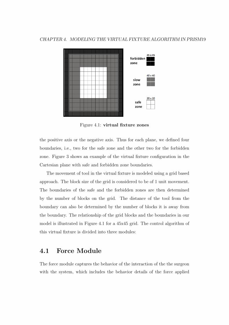
Figure 4.1: virtual fixture zones
the positive axis or the negative axis. Thus for each plane, we defined four
boundaries, i.e., two for the safe zone and the other two for the forbidden
zone. Figure 3 shows an example of the virtual fixture configuration in the
Cartesian plane with safe and forbidden zone boundaries.
The movement of tool in the virtual fixture is modeled using a grid based
approach. The block size of the grid is considered to be of 1 unit movement.
The boundaries of the safe and the forbidden zones are then determined
by the number of blocks on the grid. The distance of the tool from the
boundary can also be determined by the number of blocks it is away from
the boundary. The relationship of the grid blocks and the boundaries in our
model is illustrated in Figure 4.1 for a 45x45 grid. The control algorithm of
this virtual fixture is divided into three modules:
4.1 Force Module
The force module captures the behavior of the interaction of the the surgeon
with the system, which includes the behavior details of the force applied

CHAPTER 4. MODELING THE VIRTUAL FIXTURE ALGORITHM IN PRISM20
by the surgeon’s hand on the controlling tool. The force applied is further
divided into three components based on the Cartesian plane, i.e, fx, fy, fz.
The force applied is within a particular bound its value has been chosen in
a non-deterministic manner to cater for all possibilities for our verification.
We modeled the actual interaction of the surgeon probabilistically, such that
the probability of the force applied at a particular instance depends on the
previous force applied. Based on the statistics of surgeries, the changes in the
direction of movement of the surgical tool are relatively less likely [19][34].
Therefore, in our model, we used a probability of 0.75 for the tool to retain
the previous direction of movement and a probability of 0.25 for a change.
Pseudo code : Force
Module Force
1 : [](f = 0)→ 1/n : f = ∗;
2 : [](f > 0)→ 0.75 : f >= 0 + 0.25 : f < 0;
3 : [](f < 0)→ 0.25 : f > 0 + 0.75 : f <= 0;
endmodule
4.2 Velocity Module
The velocity module determines the instantaneous velocity of the tool us-
ing the force exerted by the surgeon and the position of the tool. The
velocity is also divided in three components, i.e., vx, vy, vz. The control
algorithm under verification is basically modeled in this module. If the
position of tool is within the safe zone, the force applied is directly trans-
lated to velocity. If the position of the tool is in the slow zone and the

CHAPTER 4. MODELING THE VIRTUAL FIXTURE ALGORITHM IN PRISM21
force is applied in the direction of the boundary, the translated velocity
is attenuated based on the scale factor K. If the tool, by any chance,
crosses the boundary of the slow zone then the velocity is completely nul-
lified and thus further movement towards the forbidden zone is prevented.
Pseudo code : Velocity
Module velocity
1 : [](p > sl&p <= sh)→ (v′ = gain ∗ f);
2 : [](p <= sl&p > bl)&f <= 0→ (v′ = (dl/Dl) ∗ gain ∗ f));
3 : [](p > sh&p < bh)&f >= 0→ (v′ = (dh/Dxh) ∗ gain ∗ f));
4 : [](p <= sl&p > bl)&f > 0→ (v′ = gain ∗ f);
5 : [](p > sh&p < bh)&f < 0→ (v′ = gain ∗ f);
6 : [](p <= bl&f >= 0)→ (v′ = gain ∗ f);
7 : [](p <= bl&f < 0)→ (v′ = 0);
8 : [](p >= bh&f > 0)→ (v′ = 0);
9 : [](p >= bh&f <= 0)→ (v′ = gain ∗ f);
endmodule
4.3 Position Module
The position module determines the number of blocks on the grid that the
tool will move depending on the velocity calculated. It is also divided into
three components px, py, pz. If the position of the tool is within the limits
specified by the grid size, the tool is allowed to move based on the velocity.

CHAPTER 4. MODELING THE VIRTUAL FIXTURE ALGORITHM IN PRISM22
However, if it is at the very edge of the grid then its movement is restricted
towards the end of grid but it is allowed to move in the opposite direction
freely.
Pseudo code : Position
module position
1 : [](p+ v < n&v > 0)→ (p′ = P + v);
2 : [](px+ v > −n&v < 0)→ (p′ = P + v);
3 : [](v = 0)|(p+ v >= n)|(p+ v <= (−n))→ (p′ = P );
endmodule
4.4 Model For Multiple Surgical Tools
Most of the surgical procedures involve multiple robotic arms that are inde-
pendently controlled. In order to formally model this scenario, we replicate
the above mentioned modules for force, velocity and position and allow them
to run concurrently. The tool boundary limits are considered to be the same
for both the tools in our model.
Pseudo code : Module Renaming
module forcex1=forcex [fx=fx1,a=b] endmodule
module forcey1=forcey [fy=fy1,a=b] endmodule

CHAPTER 4. MODELING THE VIRTUAL FIXTURE ALGORITHM IN PRISM23
module velx1=velx [vx=vx1, a=b, ax=ax1, fx=fx1] endmodule
module vely1=vely [vy=vy1, a=b, ay=ay1, fy=fy1] endmodule
module positionx1=positionx [ax=ax1, vx=vx1, a=b] endmodule
module positiony1=positiony [ay=ay1, vy=vy1, a=b] endmodule
The modules are initialized such that both the tools operate simultane-
ously and independently; a choice that makes collision a possibility as well.
We enhanced the control algorithm with collision avoidance capabilities by
treating the location of one tool as a forbidden zone boundary for the other
and vice versa. This will ensure that when the tool is moving towards the
other tool its velocity will be attenuated so that it does not collide with the
other tool. The attenuation will increase as the tool nearer the other tool
and the concept is basically to treat the previously considered static forbid-
den boundaries as dynamic ones. This is accomplished by creating a module
obstacle, which is responsible for creating boundary points from the other
tools position.
Pseudo code : Obstacle Module
module obstacle
1 : []ox < n&ox > −n→ (ox′ = ax1)&(oy′ = ayl);
endmodule
These boundary points are then used in the velocity module as ad-
ditional boundaries for the model. The velocity module then restricts the

CHAPTER 4. MODELING THE VIRTUAL FIXTURE ALGORITHM IN PRISM24
movement of the tool if they are moving towards the other tool by a factor M,
which is the ratio of distance between both tools and the maximum distance
between both the tools. The maximum distance is computed depending on
the width of the slow zone and the distance between both tools is computed
in each iteration. This will ensure that the tools are less likely to collide with
each other.
M =dobsDobs
(4.4)
Where dobs is the distance between both tools and Dobs is the maximum.

Chapter 5
Verification
In this section, the formal model of control algorithm is verified using prop-
erty specifications defined in the proposed methadology.
5.1 Deadlock Freedom
A desired characteristic of surgical robotic tools is that they never get stuck in
a particular position. This can be checked by ensuring the deadlock freedom
property for the underlying control algorithm. We verified it by using the
built in deadlock property of the PRISM model checker.
E[F deadlock]
This property checks if for some states the transition from the present to
future state will result in a deadlock. Our algorithm was found to be deadlock
free as this property was found to be failing, meaning that there is no deadlock
in the model.
25

CHAPTER 5. VERIFICATION 26
5.2 Reachability
Besides deadlock freedom, another desirable characteristic of surgical robotic
tool is the ability to reach any position, required by the surgeon, within the
virtual fixture. The fact that the control algorithm attenuates the movement
of tool, makes the verification of the reachability property even more impor-
tant as it may happen that the algorithm does not allow the tool to reach
some areas, especially the ones that are very close to the boundaries where
the attenuation is the maximum. The reachability property can be verified
by checking if, at any given time when, a force is applied to the tool, it should
move from its source and reach the required destination in a finite number
of steps. We verified this property by associating a reward with every step
of the algorithm, i.e., a reward of 1 is added to existing reward value at ev-
ery step of the algorithm. The reachability property, based on the reward
accumulated along a particular path, can now be expressed as:
R=? [px=0 & fx>0 -> F px=(width zone limit/2)-1]
This property states that if the tool position is 0 and a force is applied
in the positive direction, then the tool will eventually reach the boundary
of the forbidden zone in a bounded number of steps or rewards. The width
of the slow zone is varied and the property is verified for the x-plane. The
bound is set according to the width of slow zone. The same property can be
checked for a negative force as well. This property will return the reward or
number of steps the algorithm would take to get to the edge of the forbidden
zone. The property for the y and z-planes are given as follows
R=? [py=0 & fy>0 -> F py=(width zone limit/2)-1]
R=? [pz=0 & fz>0 -> F pz=(width zone limit/2)-1]

CHAPTER 5. VERIFICATION 27
Figure 5.1: Reachability rewards vs width of slow zone
These properties were verified for different widths of slow zones and the
resultant rewards for the x-plane, while keeping the value of the maximum
force constant, are shown in Figure 5.1. Figure 5.1 shows that the rewards
calculated are always a finite number and their value increase with the in-
crease in the width of the slow zone. This is because as the width increases
the distance from origin to the edges increases and the steps to reach them in-
crease. These verification results show that the algorithm under verification
satisfies reachability property.
The properties were also verified by varying the maximum force and Fig-
ure 5.2 shows the resultant rewards. It is observed that by increasing the
force the reward decrease, which is due to the reason that as the force in-
creases the tool moves greater distance in a single iteration and thus requires
less number of steps to reach the destination.

CHAPTER 5. VERIFICATION 28
Figure 5.2: Reachability rewards vs width of slow zone for different
max force
5.3 Out of Boundary
As described previously, the main focus of this Thesis is the formal proba-
bilistic analysis of the out-of-boundary. In the context of our modeling, the
problem can be stated as follows: At any given time during the operation, if
the surgeon starts in the safe zone then the tool should not cross the bound-
ary of forbidden zone. This property can be formally expressed in terms of
the boundary limits defined for our virtual fixtures. We can simply check
that the position of the tool is within these limits in every state, i.e.,
forall (px< bxh & px>bxl)
where px is the position of tool in the x-plane, bxh is the higher boundary
limit and bxl is the lower boundary limit. The same condition should be
checked for the y-plane and z-plane.
forall (py< byh & py>byl)
forall (pz< bzh & pz>bzl)

CHAPTER 5. VERIFICATION 29
The main issue with these properties is that they will either be true or
false. In the case of failure, we would not know the probability of failure,
which is a desirable performance characteristic as well. This limitation can
be overcome by verifying the probability of failure of this property:
P=? (px>0 & px>sxh & fx>0 => F px>bxh)
Where P is the probability of failure, sxh is the boundary of the safe
zone and fx is the force applied by the surgeon. This property verifies the
probability of crossing the boundary of the forbidden zone if the tool is in the
slow zone and accelerating towards the forbidden zone. The same property
can be checked for the y-plane and z-plane as follows:
P=? (py>0 & py>syh & fy>0 => F py>byh)
P=? (pz>0 & pz>szh & fz>0 => F pz>bzh)
These properties are for a boundary in the positive plane for each axis.
The corresponding properties for the negative planes are as follows:
P=? (px<0 & px<sxl & fx<0 => F px<bxl)
P=? (py<0 & py<syl & fy<0 => F py<byl)
P=? (pz<0 & pzl<szl & fz<0 => F pz<bzl)
The size of the virtual fixture and the boundaries has a great impact upon
the verification time and computational requirements. Therefore, in order to
avoid state-space explosion problem, the maximum size of the virtual fixture
has to be bounded from above and the boundaries for the safe and forbidden
zones have to be varied accordingly.
We verified the above-mentioned properties for different widths of slow
zone using PRISM 4.1.2 on Windows 7 64-bit operating system running on
an Intel Core2 Quad Q9100 processor at 2.66 GHz with 4.0 GB of RAM.

CHAPTER 5. VERIFICATION 30
The grid size is taken as 45x45, the maximum width of slow zone is taken
to be 20 and the maximum force limit is taken as 6. The model was verified
using different widths of slow zone ranging from 0 to 20. Similarly, we also
experimented with the maximum force limits to observe their effects on the
failure of the model.
Figure 5.3 shows the resultant probabilities computed after the verifi-
cation of the above-mentioned properties at different slow zone widths and
force limits. It is seen that when the width of slow zone is increased, the
probability of the surgical tool crossing the boundary decreases (Figure 5.3).
The probabilities change by varying the maximum limit of force. However,
after a certain width of the slow zone, the probabilities become constant.
This happens since as the width of the slow zone increases the chances of the
surgical tool to enter the forbidden region due to a sudden change of the force
in the direction of the forbidden region decreases. But no matter how much
the width is increased, if the tool is at the very edge of the forbidden region
and sudden changes of force occur in the direction of the boundary, the tool
always crosses it. Therefore the probability does not reach zero. This is val-
idated by simulating the extreme cases using PRISM. These probability are
also dependent on the maximum force limits. This shows that the algorithm
will not restrict the surgical tool from crossing the boundary if the surgeon
exhibits sudden changes near the boundary of forbidden region. The control
algorithm needs to be updated to cater for these cases.
Figure 5.4 shows the simulation of the virtual fixture model for a width of
20 units for the slow zone in the x-axis and 17 units for the slow zone in the
y-axis and a maximum and minimum force of 6 and -6 units, respectively.
The resultant x and y position of the tool is plotted for the first 1000 runs in
Figure 5. The results show that the tool crosses the boundary of the forbidden

CHAPTER 5. VERIFICATION 31
Figure 5.3: Effects of the Slow zone width on Probability of Failures
zone, i.e., 35 units, in cases where maximum force is applied towards the
boundary from the very edge, whereas the tool remains within the boundary
for other cases. The results also show that the control algorithm does not
ensure complete safety of the tool, i.e., it does not take into account the
extreme cases which results in penetration of the tool in the forbidden zone.
Probabilistic analysis played a vital role in identifying these extreme cases
as the non-probabilistic formal techniques can only tell us if the algorithm is
safe or not.
5.4 Collision Freeness
In a laparoscopic surgical operation, more than one tool is inserted inside
the patient. The corresponding control algorithm is supposed to ensure that
these tools do not collide with each other inside the patient. This property
can be defined in the context of our model by ensuring that at any given
time during the operation, the tools should not share the same position in

CHAPTER 5. VERIFICATION 32
Figure 5.4: Position of the tool(Dx=20,Dy=17,Fmax=6,Fmin=-6)
any zone. The property can be stated by considering the position of one
tool as a boundary point for other tools. For two tools, the property can be
specified in LTL as follows
forall (px!=px1)
where px is the position of the first tool in the x-plane and px1 is the position
of the second tool in x-plane. The same properties are verified for the y and
z-planes.
forall (py!=py1)
forall (pz!=pz1)
These properties when verified result in either true or false and do not give
us information about frequency of failures. In order to find quantitative
information in this regard, we compute the probability of failure associated
with these properties
P=?(px>sxl & px<sxh & px1>sxl & px1<sxh => F px=!px1)

CHAPTER 5. VERIFICATION 33
Where P is the probability of failure, px is the position of first tool, px1 is
the position of second tool, sxh and sxl are the upper and lower limits of
virtual fixture. This property is also checked for the y and z-plane.
P=?(py>syl & py<syh & py1>syl & py1<syh => F py=!py1)
P=?(pz>szl & pz<szh & pz1>szl & pz1<szh => F pz=!pz1)
The size of the virtual fixture and the limits of force have a great impact on
the verification of this property. In order to avoid the state-space-explosion
problem, the size of the virtual fixture is fixed and the maximum force applies
is varied. These properties were verified for both the models i.e. with obstacle
avoidance algorithm and without obstacle avoidance, using different force
limits keeping the width of virtual fixtures and the boundaries constant.
The properties are verified in PRISM 4.1.2 on Windows 7 64-bit operating
system running on an Intel Core2 Quad Q9100 processor at 2.66 GHz with
4.0 GB of RAM.
The grid size is taken as 45x45, the width of the slow zone is taken to
be 20. The models were verified using different force limits. The forces
for each plane are non-deterministically chosen from these limits based on
the probabilities for each force computed from actual surgical operation.
Similarly, we also experimented with the maximum force limits to observe
their effects on the failure of the model.
Figure 5.5 shows the resultant probabilities of above-mentioned properties
when verified for the model without obstacle avoidance algorithm. As shown
the probability of collision remains almost constant by varying the maximum
force limits as there is no restriction on collision and changing the force limits
will not affect the collisions.

CHAPTER 5. VERIFICATION 34
Figure 5.5: Effect of Force on Probability of Collision on initial model
Figure 5.6: Effect of Force on Probability of Collision on model with
obstacle module

CHAPTER 5. VERIFICATION 35
Figure 5.7: Effect of Force on Probability of Collision for both models
Figure 5.6 shows the resultant probabilities computed after the verifica-
tion of the above-mentioned properties for the control algorithm with obstacle
avoidance at different force limits. It is observed that as the force limits in-
crease the probability of collision increases (Figure 5.6). The probabilities
change by varying the maximum limit of force. This happens because as
the force limits increase the tools become more likely to share a same grid
point due to the fact that when the tools are near to one another and a large
amount of force is applied in the direction of the other tool then the velocity
of tool is not completely attenuated and tools are likely to collide due to
inertial movement.
Figure 5.7 shows a comparison of probabilities between both the models.
The graph clearly show that with the obstacle avoidance algorithm the prob-
ability of collision decreases but does not approach zero. As discussed above
the tool is considered as a boundary for the other tool and attenuation does
not completely restrict the tool from crossing the boundary at higher forces
as shown in previous properties, i.e., Out of Boundary properties. The re-

CHAPTER 5. VERIFICATION 36
Figure 5.8: Effect of Force on Probability of Collision for different
widths of slow zone
sults show that the control algorithm does not ensure the tools from colliding
with each other.
The properties were also verified for different widths of slow zones. The
resultant probabilities are shown in figure 5.8. It is observed that the width
of slow zone does not affect the collisions of tools and the probabilities of
collision are almost same.

Chapter 6
Testing on Al-Zahrawi
In order to validate our verification results, we tested the control algorithm
on a surgical robot Al-Zahrawi [35], named after a renowned arab surgeon
Abu al-Qasim Khalaf ibn al-Abbas Al-Zahrawi (936-1013) also known as
the father of modern surgery. Al-Zahrawi is a surgical robot for minimal
invasive surgery developed by the NUST School of Electrical Engineering
and Computer Science (SEECS) Pakistan.
The Al-Zahrawi robot consists of a Master Console (MC) and Slave Con-
sole (SC) as shown in Figure 6.1. The master console is used to track the
force applied by the surgeon and transfer it to the slave console. The surgeon
operates the tool using the master manipulator and a screen to display the
camera output. The manipulator is shown in Figure 6.2. The master manip-
ulator is made up of a mechanical mechanism and optical encoders to track
the movements of the hand of the surgeon. It offers 6 degree of freedom, i.e.,
Pitch, Yaw, Roll, back/forth and individual forceps jaw open/close.
The slave console is used to reproduce the force applied by the surgeon
37

CHAPTER 6. TESTING ON AL-ZAHRAWI 38
Figure 6.1: System Level Architecture of Al-Zahrawi
Figure 6.2: Master Manipulator

CHAPTER 6. TESTING ON AL-ZAHRAWI 39
Figure 6.3: Slave Manipulator
on the patient. The slave console consists of a servo motor based mechanical
structure to replicate the movements of the surgeon’s hand on the patient.
The slave console is shown in Figure 6.3. The slave console provides the same
degrees of freedom as the master console.
6.1 Experimental Setup
We implemented the virtual fixture based control algorithm on the Al-Zahrawi
surgical robot for our experiment. The Virtual fixture boundaries are config-
urable in the master manipulator. The master manipulator sets the value of
attenuation for the velocities based on the feedback of the positions of slave
manipulators and sends them to the slave manipulator. The slave manipula-

CHAPTER 6. TESTING ON AL-ZAHRAWI 40
Figure 6.4: Testbed for the experiment
tor is equipped with a clamper, which is a widely used surgical instrument.
Our testbed, shown in Figure 6.4. consists of three different positions, one
at the center and two at the boundaries.
6.2 Experiment Procedure
The experiment procedure is as follows
1. An object is placed at the center of the testbed.
2. The user is asked to pick that object using the telesurgical tool by
operating the master manipulator.
3. The user is then asked to move the object to any edge box and try to
place the object at the center of the corner box.
4. The boundary crossings in moving and placing the object are then
recorded until the user places the object in the box.

CHAPTER 6. TESTING ON AL-ZAHRAWI 41
Figure 6.5: Test Procedure
5. The user then picks the object and places it in the box located at the
opposite corner of the testbed
6. The boundary crossings are again recorded until the user places the
object in the box
7. The above procedure is then repeated again by removing the virtual
fixture algorithm and using a simple force to velocity translation.
40 different subjects, with various levels of expertise in robotic surgery,
were asked to do the above-mentioned procedure.
6.3 Results
The resultant boundary crossings of all the operators are logged and plotted
in Figure [?] for both the cases, i.e., with the virtual fixture control algorithm
and without the algorithm. The figure shows that the boundary crossings

CHAPTER 6. TESTING ON AL-ZAHRAWI 42
Figure 6.6: Experimental Results
of the robotic tool without the algorithm are much greater than the ones
of with the algorithm. It also shows that the tool does cross the boundary
when it is operated with the algorithm but the crossings in that case are
very less as compared to ones without the algorithm. This validates our
verification results that, given in Chapter 5, stating that the algorithm is
not completely safe with respect of restricting the robot within the operating
area and crossovers will occur if significant force is applied near the edge of
the boundary.

Chapter 7
Conclusion and Future Work
7.1 Conclusion
This thesis presents a formal verification technique for a virtual fixture based
control algorithm used in a surgical robot. In order to consider the random-
ized nature of the environment, such as the force, applied by the surgeon, and
its direction, we propose using probabilistic model checking for the verifica-
tion. The main idea is to first develop a formal Discrete-Time Markov chain
(DTMC) model of the given algorithm and its environment. This model can
then be used to analyze the corresponding probabilistic properties. The the-
sis describes the details about modelling a well-known virtual fixture based
control algorithm and also identifies the corresponding probabilistic proper-
ties. The presented probabilistic analysis for this control algorithm allowed
us to verify the probabilities associated with the properties that were found
to be failing in [16]. Our results also confirm that the properties of out of
boundary are failing but under certain conditions the probability of failure
is very less, and thus it is quite safe to use the robot under these conditions.
Since traditional model checking cannot be used to verify probabilistic prop-
43

CHAPTER 7. CONCLUSION AND FUTURE WORK 44
erties so these insights about the safe conditions cannot be obtained. This
clearly indicates the usefulness of the proposed probabilistic model checking
based approach.
7.2 Future Work
The proposed methodology has shed light on potential future directions to
interesting research areas. The future work can be done based on the results
concluded in the thesis to further refine the surgical robot control algorithm.
Some important refinements are given below:
• Enhancing the control algorithm to take care of the out-of-boundary
problem so that the tool does not enter the forbidden zone. The control
algorithm should be refined to restrict the tool completely inside the
working zones, even when a large amount of force is applied by the
surgeon near the forbidden zone.
• Formalization of multiple and small arbitrary boundaries that will also
act as obstacles for the surgical tool.
• Modifying the control algorithm to incorporate obstacle avoidance fea-
ture so that multiple tools may not collide with each other. Also this
algorithm will help in avoiding any small boundaries that are present
in the work zone in addition to the forbidden zone boundaries.

Bibliography
[1] J. F. Groote A. K. Saberi and S. Keshishzadeh. Analysis of path plan-
ning algorithms : a formal verification-based approach. In IEEE Interna-
tional Conference on Robotics and Automation (ICRA), pages 232–239,
2013.
[2] A.Platzer and J.D.Quesel. Keymaera: A hybrid theorem prover for
hybrid systems (system description). In Automated Reasoning, pages
171–178. 2008.
[3] H.Singh R.Camilli K.Delaporta R.Eustice A.Mallios
D.Mindell C.Roman B.Bingham, B.Foley and D.Sakellariou. Robotic
tools for deep water archaeology: Surveying an ancient shipwreck
with an autonomous underwater vehicle. Journal of Field Robotics,
27(6):702–717, 2010.
[4] P.D.Argenio B.Jeannet and K.Larsen. Rapture: A tool for verifying
markov decision processes. In International Conference on Concurrency
Theory (CONCUR), page 149, 2002.
[5] P.DArgenio B.Jeannet and K.Larsen. Fortuna: Model checking priced
probabilistic timed automata. In International Conference on the Quan-
titative Evaluation of Systems, pages 273–281, 2010.
45
BIBLIOGRAPHY 46
[6] C.Baier and J.P.Katoen. Principles of model checking. MIT press Cam-
bridge, 2008.
[7] T.M. Krummel C.David and J.Kenneth Salisbury. Robotic technology
in surgery: past, present, and future. The American Journal of Surgery,
188(4):2–15, 2004.
[8] C.M.Grinstead and J.L.Snell. Introduction to probability. American
Mathematical Soc., 1997.
[9] L. Geretti R. Muradore P. Fiorini D. Bresolin, L. D. Guglielmo and
T. Villa. Open problems in verification and refinement of autonomous
robotic systems. In 15th Euromicro Conference on Digital System De-
sign, pages 469–476, 2012.
[10] L. De Wulf, M.; Doyen, R. Raskin, J.-F. Alur, and G. Pappas. Almost
asap semantics: From timed models to timed implementations. In Hy-
brid Systems: Computation and Control, pages 296–310. Springer Berlin
Heidelberg, 2004.
[11] B.Wachter E.M.Hahn, H.Hermanns and L.Zhang. Infamy: An infinite-
state markov model checker. In Computer Aided Verification, pages
641–647, 2009.
[12] B.Wachter E.M.Hahn, H.Hermanns and L.Zhang. Param: A model
checker for parametric markov models. In Computer Aided Verification,
pages 660–664, 2010.
[13] B.Wachter E.M.Hahn, H.Hermanns and L.Zhang. Pass: Abstraction
refinement for infinite probabilistic models. In Tools and Algorithms for
the Construction and Analysis of Systems, pages 353–357, 2010.

BIBLIOGRAPHY 47
[14] H.K.Gazit G.E.Fainekos and G.J.Pappas. Temporal logic motion plan-
ning for mobile robots. In International Conference on Robotics and
Automation, pages 2020–2025, 2005.
[15] G.Norman and D.Parker. Quantitative verification: Formal guarantees
for timeliness, reliability and performance. Technical report, The Lon-
don Mathematical Society and the Smith Institute, 2014.
[16] J. F. Groote and R. Mateescu. Verification of temporal properties of
processes in a setting with data. In 7th International Conference on
Algebraic Methodology and Software Technology AMAST, pages 74–90,
1999.
[17] H.A.Oldenkamp. Probabilistic model checking: A comparison of tools.
Master’s thesis, University of Twente, Enschede, Netherlands, 2007.
[18] M. Reniers Y. Usenko Jan. F. Groote, A. Mathijssen and M. v. Weer-
denburg. The formal specification language mCRL2. Citeseer.
[19] J.Marescaux and M.Diana. Next step in minimally invasive surgery:
hybrid image-guided surgery. Journal of pediatric surgery, 2014.
[20] M.A.Goodrich J.M.Whetten and Y.Guo. Beyond robot fan-out: To-
wards multi-operator supervisory control. In International Conference
on Systems Man and Cybernetics, pages 2008–2015, 2010.
[21] Y. Guan C. Zhao J. Zhang L. Li, Z. Shi and H. Wei. Formal verifca-
tion of a collision-free algorithm of dual-arm robot in hol4. In IEEE
International Conference on Robotics and Automation (ICRA), pages
1380–1385, 2014.

BIBLIOGRAPHY 48
[22] L.B.Rosenberg. Virtual fixtures: Perceptual tools for telerobotic ma-
nipulation. In Virtual Reality Annual International Symposium, pages
76–82, 1993.
[23] L.Mikael. Formal verification of flexibility in swarm robotics. Thesis,
Department of Computer Science,Universit libre de Bruxelles, 2012.
[24] H.Singh L.Whitcomb, D.Yoerger and J.Howland. Advances in underwa-
ter robot vehicles for deep ocean exploration: Navigation, control, and
survey operations. In International Symposium on Robotics Research
Navigation, Control and Survery Operations, 1999.
[25] M.J.Mack. Minimally invasive and robotic surgery. The Journal of
Americal Medical Association, 285(5):568–572, 2001.
[26] K.C.Kang M.Kim and H.Lee. Formal verification of robot movements-a
case study on home service robot shr100. In International Conference
on Robotics and Automation, pages 4739–4744, 2005.
[27] G.Norman M.Kwiatkowska and D.Parker. PRISM 4.0: Verification of
probabilistic real-time systems. In International Conference on Com-
puter Aided Verification, pages 585–591, 2011.
[28] S.B.Andersson M.Lahijanian, J.Wasniewski and C.Belta. Motion plan-
ning and control from temporal logic specifications with probabilistic
satisfaction guarantees. In International Conference on Robotics and
Automation, pages 3227–3232, 2010.
[29] M.Fisher M.Salem J.Saunders K.Koay M.Webster, C.Dixon and
K.Dautenhahn. Formal verification of an autonomous personal robotic
assistant. Formal Verification and Modeling in Human-Machine Sys-
tems, 2014.

BIBLIOGRAPHY 49
[30] O.Hasan and S.Tahar. Formal Verification Methods. Encyclopedia of
Information Science and Technology, IGI Global, pages 7162–7170, 2014.
[31] B.Mittelstadt P.Kazanzides, J.Zuhars and R.H.Taylor. Force sensing
and control for a surgical robot. In International Conference on Robotics
and Automation, pages 612–617, 1992.
[32] R.Alur and T.A.Henzinger. Reactive modules. Formal Methods in Sys-
tem Design, 15(1):7–48, 1999.
[33] F.Lerda S.Scherer and E.M.Clarke. Model checking of robotic control
systems. pages 5–8, 2005.
[34] L.Kovcs T.Haidegger, B.Beny and Z.Beny. Force sensing and force con-
trol for surgical robots. In Symposium on Modeling and Control in
Biomedical Systems, 2009.
[35] S.Nasir N.Kamal T.Hassan, A.Hameed and O.Hasan. Al-zahrawi: A
telesurgical robotic system for minimal invasive surgery. volume PP,
pages 1–11, 2014.
[36] R.Alur; C.Courcoubetis; T.Henzinger, R.P.-H. Grossman;
A.Nerode; A.Ravn Ho, and H.Rischel. An algorithmic approach
to the specification and verification of hybrid systems. In Hybrid
Systems, pages 209–229. Springer Berlin Heidelberg, 1993.
[37] G.Jallo K.Hayes N.Nakajima N.Hata T.Xia, C.Baird and P.Kazanzides.
An integrated system for planning, navigation and robotic assistance for
skull base surgery. The International Journal of Medical Robotics and
Computer Assisted Surgery, 4(4):321–330, 2008.

BIBLIOGRAPHY 50
[38] A.Platzer Y.Kouskoulas, D.Renshaw and P.Kazanzides. Certifying the
safe design of a virtual fixture control algorithm for a surgical robot. In
International conference on Hybrid systems: computation and control,
pages 263–272, 2013.