FORMAL SCENARIO DEFINITION LANGUAGE FOR...
68
SE690 GRP Page 1 FORMAL SCENARIO DEFINITION LANGUAGE FOR AVIATION: AIRCRAFT LANDING CASE STUDY BHARVI CHHAYA EMBRY-RIDDLE AERONAUTICAL UNIVERSITY GRADUATE RESEARCH PROJECT 04/27/16 VERSION 0.5 Name Signature Date Student Bharvi Chhaya 04/27/2016 GRP Advisor Dr. Shafagh Jafer 04/28/2016 MSE Coordinator / Department Chair Dr. Massood Towhidnejad Massood Towhidnejad 04/30/2016
Transcript of FORMAL SCENARIO DEFINITION LANGUAGE FOR...

SE690 GRP Page 1
FORMAL SCENARIO DEFINITION
LANGUAGE FOR AVIATION:
AIRCRAFT LANDING CASE STUDY
BHARVI CHHAYA
EMBRY-RIDDLE AERONAUTICAL UNIVERSITY
GRADUATE RESEARCH PROJECT
04/27/16
VERSION 0.5
Name Signature Date
Student Bharvi Chhaya
04/27/2016
GRP Advisor Dr. Shafagh Jafer
04/28/2016
MSE Coordinator / Department Chair
Dr. Massood Towhidnejad Massood Towhidnejad 04/30/2016

SE690 GRP Page 2
REVISION HISTORY Date Version Description
04/11/16 0.1 Initial document with Introduction and Literature Review
04/13/16 0.2 Added Ontology description in Methodology
04/21/16 0.3 Completed Methodology section
04/23/16 0.4 Completed draft of full report
04/27/16 0.5 Minor corrections based on advisor’s feedback

SE690 GRP Page 3
ACKNOWLEDGEMENTS I would like to thank Dr. Shafagh Jafer for her guidance through every step of this project and Dr. Umut
Durak for his involvement and expert feedback on the design of this metamodel.
I would also like to thank my parents for believing in me and for supporting my ambitions. I am grateful
to my roommate, Shibani, for being my sounding board when I was stuck and needed someone to talk to,
and also for helping me create and practice my presentation.

SE690 GRP Page 4
ABSTRACT Although the importance of scenarios in modeling and simulation has long been well known, there still
exists a lack of common understanding and standardized practices in simulation scenario development.
This project describes a proposed domain-specific language to provide a standard scenario specification
that will lead to a common mechanism for verifying and executing aviation scenarios, effective sharing of
scenarios among various simulation environments, improve the consistency among different simulators
and simulations and even enable the reuse of scenario specifications. Based on DSL design methodologies,
the proposed Aviation Scenario Definition Language (ASDL) will provide a well-structured definition
language to formally specify complete aircraft landing scenarios. In order to capture the necessary
constructs for a simulation scenario, Simulation Interoperability Standards Organization (SISO) Base
Object Model (BOM) is adopted as the baseline metamodel. This baseline is extended using the
fundamentals of aircraft landing that capture all the domain-related concepts and terminology as
constructs. By taking a formal approach in defining aviation scenarios, ASDL aims at providing
consistency and completeness checking, and model to text transformations capabilities for various targets
in the aviation scenario definition domain. The results of this work will be used to develop a graphical
modeling environment to automatically transform scenario models into executable scenario scripts. The
work presented here is the first stepping stone in formal scenario definition in aviation domain.

SE690 GRP Page 5
TABLE OF CONTENTS Revision History ............................................................................................................................................ 2
Acknowledgements ....................................................................................................................................... 3
Abstract ......................................................................................................................................................... 4
Table of Contents .......................................................................................................................................... 5
List of Figures ............................................................................................................................................ 7
List of Tables ............................................................................................................................................. 9
List of Abbreviations/Acronyms .............................................................................................................. 10
1. Introduction ............................................................................................................................................ 11
2. Literature Review .................................................................................................................................... 13
Summary ................................................................................................................................................. 16
3. Methodology ........................................................................................................................................... 17
3.1. Ontology ........................................................................................................................................... 17
3.2. Modeling Tool Selection .................................................................................................................. 22
3.3. Overview of Eclipse Modeling Framework (EMF) ............................................................................ 23
3.3.1. Modeling Concepts ................................................................................................................... 23
3.3.2. Tool Familiarization ................................................................................................................... 23
3.4. Design of Model ............................................................................................................................... 24
3.4.1. Design Process .......................................................................................................................... 24
3.4.2. Class Diagram For Aviation Scenario Model ............................................................................. 26
3.4.3. Class Descriptions For Aviation Scenario Model ....................................................................... 26
3.4.3.1. LandingScenario Class ........................................................................................................ 26
3.4.3.2. Aircraft Class ...................................................................................................................... 27
3.4.3.3. State Class .......................................................................................................................... 28
3.4.3.4. Airport Class ....................................................................................................................... 29
3.4.3.5. Runway Class ...................................................................................................................... 29
3.4.3.6. ATC Class ............................................................................................................................ 30
3.4.3.7. Pilot Class ........................................................................................................................... 30
3.4.3.8. FlightProperties Class ......................................................................................................... 30
3.4.3.9. Weather Class .................................................................................................................... 30
3.4.3.10. Summary of Classes in Aviation Model ............................................................................ 31

SE690 GRP Page 6
3.4.4. Class Diagram for BOM Integration With Aviation Entities ...................................................... 32
3.4.5. Class Descriptions for BOM Classes .......................................................................................... 33
3.4.5.1. ConceptualScenario Class .................................................................................................. 33
3.4.5.2. ScenarioIdentification Class ............................................................................................... 34
3.4.5.3. ConceptualEntity Class ....................................................................................................... 34
3.4.5.4. PatternOfInterplay Class .................................................................................................... 34
3.4.5.5. PatternAction Class ............................................................................................................ 35
3.4.5.6. StateMachine Class ............................................................................................................ 35
3.4.5.7. ExitCondition Class ............................................................................................................. 35
3.4.5.8. Event Class ......................................................................................................................... 36
3.4.5.9. Summary of Classes in BOM Model ................................................................................... 36
3.4.6. Integrated Class Diagram .......................................................................................................... 38
3.5. Scenario Generation and Model Implementation ........................................................................... 39
4. Results and Analysis ................................................................................................................................ 46
4.1. Scenarios .......................................................................................................................................... 46
4.1.1 Example Scenario 1: Normal Landing ........................................................................................ 46
4.1.2. Example Scenario 2: Crosswind Landing ................................................................................... 51
4.1.3. Example Scenario 3: Short Field Landing .................................................................................. 52
4.1.4. Example Scenario 4: Soft/Unprepared Field Landing ............................................................... 52
4.1.5. Example Scenario 5: Normal Landing with Holding .................................................................. 53
4.2 Verification and Validation ............................................................................................................... 55
5. Conclusions ............................................................................................................................................. 55
5.1. Summary .......................................................................................................................................... 55
5.2. Future Work ..................................................................................................................................... 55
6. References .............................................................................................................................................. 56
Appendices .................................................................................................................................................. 58
Appendix A: Definitions in Ontology ....................................................................................................... 58
Appendix B: ATC Communication Phraseology ...................................................................................... 66

SE690 GRP Page 7
LIST OF FIGURES Figure 1: High-Level View of ASDL Ontology .............................................................................................. 17
Figure 2: Elements present in ATC Class in Ontology ................................................................................. 18
Figure 3: Elements present in Aircraft Class in Ontology............................................................................ 19
Figure 4: Elements present in Airport Class in Ontology ............................................................................ 21
Figure 5: Elements present in Weather Class in Ontology ......................................................................... 22
Figure 6: Typical Scenario Development Process (GSD Product Development Group, SISO 2014) ........... 24
Figure 7: Overall Class Diagram of Aviation Entities ................................................................................... 26
Figure 8: Subclasses which inherit from the LandingScenario class ........................................................... 27
Figure 9: Classes contained in LandingScenario class ................................................................................. 27
Figure 10: References and Attributes of Aircraft Class ............................................................................... 28
Figure 11: State Class and its Associations in the Model ............................................................................ 28
Figure 12: Properties of State Class ............................................................................................................ 28
Figure 13: State Machine Diagram for Aircraft Landing Model .................................................................. 29
Figure 14: Properties of Airport Class ......................................................................................................... 29
Figure 15: Properties of Runway Class ........................................................................................................ 29
Figure 16: Properties of ATC Class .............................................................................................................. 30
Figure 17: Properties of Pilot Class ............................................................................................................. 30
Figure 18: Properties of FlightProperties Class ........................................................................................... 30
Figure 19: Properties of Weather Class ...................................................................................................... 31
Figure 20: BOM Metamodel used as framework for ASDL (Durak, et al. 2014) ......................................... 33
Figure 21: Properties of ConceptualScenario Class .................................................................................... 34
Figure 22: Properties of ScenarioIdentification Class ................................................................................. 34
Figure 23: Properties of ConceptualEntity Class ......................................................................................... 34
Figure 24: Properties of PatternOfInterplay Class ...................................................................................... 35
Figure 25: Properties of PatternAction Class .............................................................................................. 35
Figure 26: Properties of StateMachine Class .............................................................................................. 35
Figure 27: Properties of ExitCondition Class ............................................................................................... 35
Figure 28: Properties of Event Class ........................................................................................................... 36
Figure 29: Integrated metamodel including ASDL and BOM entities ......................................................... 38
Figure 30: Relationship between conceptual model and conceptual scenario (GSD Product Development
Group, SISO 2014) ....................................................................................................................................... 39
Figure 31: EMF Generator Model of LandingIntegration Ecore Model ...................................................... 40
Figure 32: Generated Java code for model classes ..................................................................................... 41
Figure 33: A snapshot of Aircraft.java code ................................................................................................ 42
Figure 34: Creating a new LandingIntegration Model ................................................................................ 43
Figure 35: Selecting ConceptualScenario as the Base Object ..................................................................... 43
Figure 36: Creating instances of child classes ............................................................................................. 44
Figure 37: Entering the properties of ScenarioIdentification ..................................................................... 44
Figure 38: Filling in associated object values in conceptual scenario ......................................................... 45
Figure 39: Conceptual Scenario Attributes for Normal Landing ................................................................. 46

SE690 GRP Page 8
Figure 40: Properties of Conceptual Scenario for Normal Landing ............................................................ 47
Figure 41: Properties of Scenario Identification for Normal Landing ......................................................... 47
Figure 42: Properties of Normal Landing Class for Normal Landing ........................................................... 47
Figure 43: Properties of Aircraft for Normal Landing ................................................................................. 47
Figure 44: Properties of Pilot for Normal Landing ...................................................................................... 47
Figure 45: Properties of Airport for Normal Landing .................................................................................. 48
Figure 46: Properties of Runway for Normal Landing ................................................................................ 48
Figure 47: Properties of ATC for Normal Landing ....................................................................................... 48
Figure 48: Properties of Flight Properties for Normal Landing ................................................................... 48
Figure 49: Properties of Weather for Normal Landing ............................................................................... 48
Figure 50: New Runway for Airport DAB .................................................................................................... 49
Figure 51: Change in Airport Runway details based on creation of new Runway ...................................... 49
Figure 52: Pattern of Interplay for Normal Landing.................................................................................... 50
Figure 53: State Machine of the Aircraft for Normal Landing .................................................................... 50
Figure 54: Validation completed for model ................................................................................................ 50
Figure 55: High crosswind component in Ex_Scen_02 ............................................................................... 51
Figure 56: Change in Pattern of Interplay for Crosswind Landing .............................................................. 51
Figure 57: Change in Pattern of Interplay for Short-Field Landing ............................................................. 52
Figure 58: Change in Pattern of Interplay for Soft Field Landing ................................................................ 53
Figure 59: Change in Pattern of Interplay for Normal Landing with Holding Pattern ................................ 54
Figure 60: Change in State Machine for Normal Landing with Holding Pattern ......................................... 54

SE690 GRP Page 9
LIST OF TABLES Table 1: Definition of terms in base class of ASDL Ontology ...................................................................... 18
Table 2: Definition of terms in ATC class of ASDL Ontology ....................................................................... 18
Table 3: Definition of terms in Aircraft class of ASDL Ontology.................................................................. 19
Table 4: Definition of terms in Airport class of ASDL Ontology .................................................................. 21
Table 5: Definition of terms in Weather class of ASDL Ontology ............................................................... 22
Table 6: Summary of Class Attributes and Associations for Aviation Scenario Model ............................... 31
Table 7: Summary of all Class Attributes and Associations for BOM Model .............................................. 36
Table 8: Description of Scenarios used for Analysis ................................................................................... 46

SE690 GRP Page 10
LIST OF ABBREVIATIONS/ACRONYMS
Abbreviation Term
AGL Above Ground Level
ASDL Aviation Scenario Definition Language
ATC Air Traffic Control
ATM Air Traffic Management
BOM Base Object Model
EMF Eclipse Modeling Framework
GPS Global Positioning System
IFR Instrument Flight Rules
ILS Instrument Landing System
M&S Modeling and Simulation
MDE Model-Driven Engineering
NAS National Airspace System
SISO Simulation Interoperability Standards Organization
VFR Visual Flight Rules
XML Extensible Markup Language

SE690 GRP Page 11
1. INTRODUCTION Modeling and simulation is a swift, accurate and cost-effective method to investigate potential solutions
to problems. A model is defined as a three-dimensional representation of a person or thing or of a
proposed structure, typically on a smaller scale than the original. A simulation is a method for
implementing a model. It is the process of conducting experiments with a model for the purpose of
understanding the behavior of the system modeled under selected conditions or of evaluating various
strategies for the operation of the system within the limits imposed by developmental or operational
criteria (Shannon 1975).
In the case of aviation applications, flight simulation refers to the process of simulating an aircraft and its
dynamics through the use of computer systems and advanced software. Modern flight simulators are used
for initial and advanced training and for proficiency maintenance and evaluation. They have become
integral aspects of the research, development, test, and evaluation cycle (Moroney and Lilienthal 2008).
In addition to cost-effectiveness, the biggest advantage of using simulators is that simulation provides a
means for experiencing normal conditions in a safe and nonthreatening environment. It also allows
exposure to controlled critical conditions. In some cases, due to safety concerns, a simulator may be the
only way to teach certain flight maneuvers or expose air crews to conditions they are unlikely to
experience under actual flight conditions, so that they can be prepared, but without exposing them to
real danger.
The execution of any simulation requires a clearly-defined scenario which is being investigated. This
simulation scenario can be defined as the specification of initial and terminal conditions, significant events
and the environment as well as the major entities, their capabilities, behavior and interactions over time.
Although the importance of scenarios in modeling and simulation has long been well known, there still
exists a lack of common understanding and standardized practices in simulation scenario development. It
is an extensive process beginning with the stakeholders’ descriptions of the scenario and finishing with
the generation of the corresponding executable specification (Durak, et al. 2014).
Generating scenarios for real-time simulators is currently a resource intensive activity. Typically, the
design of a simulator does not concentrate on generation and manipulation of input data, but instead is
focused on the execution of the simulation. In the current/typical process, after a scenario is developed,
it is not generally portable to any other simulator other than the one on which it was developed. Where
scenario generation capabilities are provided currently, these scenario generation methods are tightly
coupled to a specific simulator and cannot be used to generate or manipulate scenarios for other
simulators (Signor, et al. 2004). This indicates the necessity for a well-defined language for aviation which
would enable the reuse of scenario generation methods among different simulators.
This work targets aviation scenario generation by proposing a Domain-Specific Language (DSL). A DSL is a
custom tailored computer language specialized for a particular application domain (Hoisl, Sobernig and
Strembeck 2014). DSL is created to specifically target problems in a specific domain, highlighting the main
features, requirements, constraints, and characteristics of that domain. With DSL, developers construct
models that are specific to their application. Such models are composed of elements and relationships
that are verified by DSL to be valid for that application. One of the greatest benefits of DSL is allowing non-

SE690 GRP Page 12
developers and people who do not know the domain understand the overall design. This is normally
supported by allowing graphical modeling, where DSL provides a drag and drop capability to construct
models. DSL with model to text capabilities would then allow for automatic generation of source code
from model.
The language proposed in this report is intended for the aviation domain and is called the Aviation
Scenario Definition Language (ASDL). ASDL aims at providing a standard scenario specification that will
lead to a common mechanism for verifying and executing aviation scenarios, effective sharing of scenarios
among various simulation environments, improve the consistency among different simulators and
simulations and enable the reuse of scenario specifications. Based on Domain-Specific Language (DSL)
design methodologies, ASDL will provide a well-structured definition language to define departure,
enroute, re-route, and landing scenarios. This work focuses on aircraft landing scenarios as a case study
to demonstrate the feasibility of creation and significance of such a language. For the purposes of this
study, a landing scenario refers to the last part of a flight, where the aircraft returns to the ground.
By taking a formal approach in defining aviation scenarios, the aim of this research project is to provide
consistency and completeness checking, and model to text transformation capabilities for various targets
in the aviation scenario definition domain.

SE690 GRP Page 13
2. LITERATURE REVIEW A thorough survey of the literature was conducted on the topics of domain-specific languages, ontologies
and scenario generation. Some of the applicable resources that were discovered are summarized and
discussed here.
Sinlapakun, Sakon, and Yachai Limpiyakorn. 2013. "Domain Specific Language for Collaborative
Determination of Separation Minima between Aircrafts." International Journal of Software Engineering
and its Applications 399-414.
This paper was published in 2013 and has mainly been used for research into the background of Domain-
Specific Languages in aviation. In particular, this paper describes the business rules that define aircraft
separation and uses them as a base to create the Aeronautical Rules Script Language (ASRL). The purpose
of ASRL is to provide sufficient elements for determining the required longitudinal aircraft separation at
the planning phase, i.e., before the airplanes take off.
A short description of the ASRL design has been given in the paper, along with some details of the scheme
used. This is divided into two parts: (1) rule declaration which can be modeled using a class diagram, and
(2) rule adoption which shows how the list of rules created will be applied at the specified times. The
paper goes on to describe the verification and evaluation of ASRL, and concludes that the implemented
language and its services are trustworthy and function accurately as desired.
However, ASRL is only designed for a particular collaborative environment aiming at determining the
separation minima required between aircrafts at the planning phase. This makes it a useful resource for
understanding the concepts of DSL as they apply to this project, but it suggests a need for a broader
aviation-specific domain language which can be used for purposes beyond this single task.
Hilera, José, and Luis Fernández-Sanz. 2010. "Developing Domain-ontologies to Improve Software
Engineering Knowledge." International Conference on Software Engineering Advances.
This paper was published in 2010 and explains the concept of an ontology as being “a formal
representation of a knowledge domain”. It includes classes which represent the concepts of the domain,
properties which show the relationships between concepts, and axioms which represent any applicable
restrictions.
This paper explains the necessity of creating ontologies in the software domain in order to enable
modeling, sharing and reusing of knowledge of organizations or disciplines. Availability of such ontologies
would facilitate their use as models for learning the principles of the domain. One other benefit of using
ontologies is their capacity to be extended using new knowledge when this is generated. An example
ontology is created and explained in this work in order to support its ideas. The paper concludes that the
authors are now developing a tool for managing knowledge using open source libraries which enable
working with ontologies in different settings.
Oaks, Robert, Shurong Liu, David Zhou, Mike Paglione, and William J. Hughes. 2003. "Methodology for
the generation of air traffic scenarios based on recorded traffic data." Digital Avionics Systems
Conference (DASC). Indianapolis: IEEE. 5-C.

SE690 GRP Page 14
Published in 2003, this paper presents a methodology to generate air traffic scenarios for support of
testing and analysis of Air Traffic Management (ATM) decision support tools. This method includes three
steps in order to generate the scenarios based on recorded traffic data: (1) data extraction, during which
traffic data obtained from various sources is extracted and placed into relational database tables, (2) data
manipulation, where aspects of the data are changed or time-shifted in order to induce a conflict, and (3)
the actual scenario generation process where scenarios are created based on the traffic data retrieved
from the modified database tables and writes it in either P320 input format or ASCII format.
The paper describes some examples of use of this system for the User Request Evaluation Tool (URET)
tested by the FAA. This tool was used for accuracy testing, risk reduction and a weather forecast error
impact study. It was able to generate high levels of conflicts with relatively short traffic samples, hence
showing its usefulness and efficiency. The paper goes on to describe possible upgrades to this
methodology.
Gauci, J., and D. Zammit-Mangion. 2008. "A Rapid Scenario Generation Tool for Repeatable Simulated
Traffic Conflicts in Flight Simulation." The 26th International Congress of the Aeronautical Sciences.
This paper describes the need for a rapid scenario prototyping tool to support the evaluation of a runway
conflict alerting system, called the Runway Collision Avoidance Function (RCAF). The tool developed for
this purpose has three main components: (1) a traffic motion generator to generate the flight paths, (2) a
scenario definition and control unit to define the runway conflict scenarios using the trajectories created
earlier, and (3) a dynamic traffic control unit to control the speed of the target to maintain the intended
leeway in the scenario conflict.
In this case, the scenarios are defined in XML format. Each scenario is given a unique ID and a definition
beginning with a brief description of the scenario. The user can then specify a number of conditions, such
as ownship speed, ownship position, ownship distance and a time delay, that have to be satisfied before
the target begins moving. Thus, this tool allows the user to define a whole set of scenarios related to
runway maneuvers. For execution, the user selects one of the available scenarios and the information
related to that scenario is loaded from the XML file. During the scenario, when the specified conditions
are met, data is read from the appropriate target trajectory file and is transmitted to the simulator to
check for the generation of the appropriate alerts by the RCAF. The paper concludes that this tool was
shown to provide flexibility and repeatability in scenario execution. The performance of the tool has
proved to be appropriate for the purpose it was defined for, that is, for rapid generation of scenarios of
traffic trajectories and conflicts. The need for and success of this project shows the importance of being
able to generate scenarios and how widely these are used in the aviation field.
Signor, David, Paul Davis, Sandra Lozito, Anthony Andre, Doug Sweet, and Erin Wallace. 2004. "Efficient
Air Traffic Scenario Generation." AIAA 4th Aviation Technology, Integration and Operations (ATIO)
Forum. Chicago.
This paper begins by talking about the current process for scenario generation which is typically a resource
intensive activity. The non-portability of current scenario generation capabilities of software has also been
brought up and the need to have independent creation of Human-In-The-Loop (HITL) simulation scenarios

SE690 GRP Page 15
has been suggested. In a response to these shortcomings, this paper describes the ongoing research to
develop a tool called AvScenario, which would allow researchers to quickly and easily generate and
evaluate scenarios on a single desktop computer rather than using a target simulator to create scenarios.
AvScenario is described as a modern graphically oriented application that automates and simplifies many
of the tasks associated with scenario generation. It is intended to be a general-purpose tool that would
be able to work with multiple input data formats and would produce generically formatted scenario data
that can be targeted to specific simulators.
The scenario generation part of the AvScenario prototype consists of several functions: (1) a route
generator in the form of a 2-D ground track, (2) a flight plan generator consisting of the complete set of
data required to fly an aircraft from one airport to another, (3) a NAS modification module which allows
for creation, deletion and modification of NAS data elements in order to support modeling future airspace
configurations, (4) an event creator for automatic calculation of initial conditions, given a user-specified
event that occurs during the simulation, (5) a scenario randomizer in order to diminish the learning effect
of the participant (to disguise that a similar scenario has already been tested before), and (6) a schedule
generator to automatically generate the future schedule for several flights simultaneously.
The future plans described in this paper include ideas for future releases such as a fast-time simulation
scenario editor and non-NAS simulation/scenario data generation and manipulation. However, Seagull
Technology, the company that was performing this research, has since been taken over. No information
about AvScenario, with the exception of this paper about the prototype, can be found any more. It appears
that this project and line of research has been abandoned by the authors.
Durak, Umut, Okan Topcu, Robert Siegfried, and Halit Oguztuzun. 2014. "Scenario Development: A
Model-Driven Engineering Perspective." Simulation and Modeling Methodologies, Technologies and
Applications (SIMULTECH), 2014 International Conference on. IEEE. 117-124.
This work presented in 2014 lays down the foundation for the research presented in this report. It
proposes a scenario development process adopting a Model-Driven Engineering (MDE) perspective. This
process suggests that one shall construct a model of the system to be built and then proceed with a series
of transformations to obtain an executable system.
The paper begins by defining scenarios and explaining the difference between conceptual and executable
scenarios. It goes on to describe the development process using MDE and the proposed steps for this
project. The paper explains that the aim is to start with a metamodel to enable building a conceptual
model, and then to provide transformation of the model from the source. In order to support this idea,
the paper describes a sample implementation of this method using the Base Object Model (BOM)
metamodel.
This metamodel introduces the sequence of events and interplay between various simulation elements.
The conceptual scenario describes includes identifying information, a set of conceptual entities, a pattern
of interplay, events as well as state machines consisting of a number of states. Examples are given of
entities that could be created related to a flight scenario, but these have not been implemented. The
paper recommends that the next step would be to set up these entities and integrate them into the model

SE690 GRP Page 16
in order to define flight scenarios. It outlines a proposed development process, which has been explained
using a case study.
The ASDL research project intends to follow the process laid out by this paper and use the base metamodel
and extend it to constitute a set of entities that are specific to the aviation domain. This metamodel can
then be used to accurately model conceptual flight scenarios which can later be transformed into
executable scenarios and deployed in simulators.
SUMMARY Two different aspects of this project have been studies in the literature review in this section. The first is
the idea of domain-specific languages. DSL seems to be a well-defined way of providing a central source
of information which can be reused by specific applications for that domain. This recognizes the current
need for an aviation-specific domain language. The next paper went on to explain the concept and
importance of ontologies in software creation. This led to the construction of a basic aviation ontology
being the first step required in the creation of ASDL.
The second concept is that of scenario generation. As has been observed in the summary of various papers
above, there are several researchers who recognize the need for an automated scenario generation
process and who have been working on it independently. Researchers tend to use various simulators and
associated tools, and create customized data processing programs in order to modify an existing data set
into the desired scenario. This leads to the drawback that each scenario generator is currently specific to
the application and simulator it is being used for. Also, it appears that each of these research projects
utilize their own method for this purpose which they develop from beginning to end. A lot of resources
appear to be used for similar tasks which could be saved if there was a process to reuse some aspects of
other projects. This leads to the conclusion that if there was a common standardized language for defining
aviation scenarios, a lot of duplicate work and efforts could be avoided. Each related project (for example:
air traffic scenarios, runway collision avoidance scenarios and full-flight simulation scenarios) could use
relevant information (airport, runway, flight plan objects) from this language in order to build their specific
scenarios which could then be ported to and read by any simulator they choose. This is the main purpose
of creating the Aviation Scenario Definition Language which could benefit all aspects of the aviation
community for modeling and simulating the various features of flight.

SE690 GRP Page 17
3. METHODOLOGY This section describes the methodology followed to create the model of the aircraft landing scenario. The
ontology creation is described first, followed by an overview of the tool selected to create the model and
then a discussion of the actual design and implementation of the model is presented.
3.1. ONTOLOGY An ontology describes the concepts and relationships that are important in a particular domain, providing
a vocabulary for that domain as well as a computerized specification of the meaning of terms used in the
vocabulary (Yao and Zhang 2009). One of the benefits of using ontologies is their capacity to be easily
extended using new knowledge generated by experts so all existing ontologies can be used as a starting
point for further development (Hilera and Fernández-Sanz 2010).
In order to capture aircraft landing details, it is essential to have a definitions reference list that highlights
all key terminology as well as procedures and operations that are communicated between the pilot and
ATC. The United States’ FAA and European SESAR programs provide inclusive glossaries that provide key
terminology and concept of operations (Federal Aviation Administration 2012) (SESAR n.d.). A review of
existing ontologies resulted in one aviation ontology being discovered. However, this described the
structural and physical entities of an aircraft, and hence did not provide any useful terms that could be
reused. Thus, a new aviation-specific ontology was created for this project, which was further used to
develop the model and in the implementation of the scenarios.
The ontology consists of two parts: keywords that describe the physical model and operation of flights,
and words that describe key communication between the control tower and pilots. The appendices list all
these keywords along with their definitions and use. Once over 100 keywords were identified, the
primarily used terms were added to a basic ontology created using Protégé (Alatrish 2013), which saves
them in OWL format. The Web Ontology Language (Bechhofer 2009) is a language for defining ontologies
on the Web. An OWL ontology describes a domain in terms of classes, properties and individuals and may
include rich descriptions of the characteristics of those objects (Protégé Home Page n.d.).
An ontology focuses mainly on classes which describe the concepts of the domain. It follows a hierarchical
model where subclasses are all necessarily a part of the superclass (Noy and McGuinness 2001). The ASDL
ontology has four base classes: Air_Traffic_Control, Aircraft, Airport and Weather. This can be seen in
Figure 1 below. All these terms have been defined in Table 1.
Figure 1: High-Level View of ASDL Ontology

SE690 GRP Page 18
Table 1: Definition of terms in base class of ASDL Ontology
Term Definition
Air Traffic Control A service operated by appropriate authority to promote the safe, orderly and
expeditious flow of air traffic.
Aircraft Any machine that can derive support in the atmosphere from the reactions of the
air other than the reactions of the air against the earth’s surface.
Airport An area on land or water that is used or intended to be used for the landing and
takeoff of aircraft and includes its buildings and facilities, if any.
Weather The state of the atmosphere at a place and time as regards heat, dryness, sunshine,
wind, rain, etc.
As shown in Figure 2, the ATC class includes a Controller and various key terms that need to be used in
conversation. These have been defined below in Table 2.
Figure 2: Elements present in ATC Class in Ontology
Table 2: Definition of terms in ATC class of ASDL Ontology
Term Definition
Abort To terminate a preplanned aircraft maneuver; e.g., an aborted takeoff.
Acknowledge “Let me know that you have received and understood this message.”
Affirmative “Yes.”
Alert A notification to a position that there is an aircraft-to-aircraft or aircraft-to-airspace
conflict, as detected by Automated Problem Detection (APD).
Cleared ATC authorization for an aircraft to execute any specific action. Needs to be followed by
the action name, such as “Cleared Approach”, “Cleared for Takeoff”, “Cleared to Land”,
etc.
Controller A person authorized to provide air traffic control services.
Error System-generated notification of an error.
Hold Position Instruction to hold the current position.

SE690 GRP Page 19
Immediately Instruction to immediately comply with the associated instruction to avoid an imminent
situation.
Mayday
Mayday
Mayday
Indication of an emergency situation.
Negative “No” or “Permission not granted” or “That is not correct.”
Standby Indication that the message will be responded to shortly.
The main part of this ontology involves the aircraft and its properties. Figure 3 shows the subclasses of
the Aircraft class. The Flight_Properties subclass describes the rules (IFR or VFR) that govern the flight, the
speed of the aircraft, the fuel remaining and has three other subclasses: controls (pitch, roll and turn
rates), location (altitude, latitude, longitude) and time (arrival time, departure time and ACLT). The
physical properties subclass contains the call sign, type of aircraft and its weight class. The definitions of
all these terms can be found in Table 3.
Figure 3: Elements present in Aircraft Class in Ontology
Table 3: Definition of terms in Aircraft class of ASDL Ontology
Term Definition
Actual Calculated
Landing Time
ACLT is a flight’s frozen calculated landing time. This time will not be updated in
response to the aircraft’s progress.

SE690 GRP Page 20
Aircraft Type The ICAO aircraft type designator, which is a three- or four-character alphanumeric
code designating every aircraft type that may appear in flight planning.
Airspeed The speed of an aircraft relative to its surrounding air mass. The unqualified term
“airspeed” means one of the following:
a. Indicated Airspeed− The speed shown on the aircraft airspeed indicator. This is the
speed used in pilot/controller communications under the general term “airspeed.”
b. True Airspeed− The airspeed of an aircraft relative to undisturbed air. Used primarily
in flight planning and en route portion of flight. When used in pilot/controller
communications, it is referred to as “true airspeed” and not shortened to “airspeed.”
Altitude The vertical distance of a level, a point or an object considered as a point, measured
from mean sea level (MSL).
Approach
Category
A grouping of aircraft based on a speed of 1.3 times the stall speed in the landing
configuration at maximum gross landing weight. An aircraft must fit in only one
category. The categories are as follows:
a. Category A− Speed less than 91 knots.
b. Category B− Speed 91 knots or more but less than 121 knots.
c. Category C− Speed 121 knots or more but less than 141 knots.
d. Category D− Speed 141 knots or more but less than 166 knots.
e. Category E− Speed 166 knots or more.
Arrival Time The time an aircraft touches down on arrival.
Call Sign Call signs in aviation generally depend upon the type of flight operation. In most cases,
the call sign corresponds to the aircraft's registration or tail number.
Controls The properties that define the behavior of the flight.
Departure Time The time an aircraft becomes airborne.
Flight Properties The properties of an aircraft while it is airborne. This collection mainly lists variable
properties that change during the course of the flight.
Flight Rules The set of rules that govern the flight: VFR or IFR. VFR stands for Visual Flight Rules and
IFR means Instrument Flight Rules.
Fuel Remaining A phrase used by either pilots or controllers when relating to the fuel remaining on
board until actual fuel exhaustion.
Ground Speed The speed of an aircraft relative to the surface of the earth.
Latitude The angular distance of the aircraft north or south of the earth's equator, usually
expressed in degrees and minutes.
Location The place or position of the aircraft at a given time.
Longitude The angular distance of the aircraft east or west of the meridian at Greenwich, England,
usually expressed in degrees and minutes.
Pilot The person who operates the flying controls of the aircraft.
Pitch Current pitch angle of the aircraft relative to horizontal plane.
Pitch Rate Current rate of change of pitch direction.
Roll Current roll angle of the aircraft in decimal degrees.
Roll Rate Current rate of change of pitch angle.

SE690 GRP Page 21
Turn Rate Current rate of change of ground track.
Weight Class For the purposes of Wake Turbulence Separation Minima, ATC classifies aircraft as
Heavy, Large, and Small as follows:
a. Heavy− Aircraft capable of takeoff weights of 300,000 pounds or more whether or
not they are operating at this weight during a particular phase of flight.
b. Large− Aircraft of more than 41,000 pounds, maximum certificated takeoff weight,
up to but not including 300,000 pounds.
c. Small− Aircraft of 41,000 pounds or less maximum certificated takeoff weight.
The Airport class includes an identifier, the details of terminals and gates present in the airport, its
elevation as well as runway details. Each runway’s information also includes its heading. These can be
seen below in Figure 4, with the definitions in Table 4.
Figure 4: Elements present in Airport Class in Ontology
Table 4: Definition of terms in Airport class of ASDL Ontology
Term Definition
Elevation The highest point of an airport’s usable runways measured in feet from mean sea level.
Identifier The three-character airport code assigned by the International Air Transport Association.
Runway A defined rectangular area on a land aerodrome prepared for the landing and take-off of
aircraft.
Heading The magnetic direction that corresponds with the runway centerline extended, not the
painted runway number.
Terminal A building at an airport where passengers transfer between ground transportation and the
facilities that allow them to board and disembark from aircraft.
Gate A gate that allows passengers to go from the terminal to the airplane. Also referred to as the
parking space for the aircraft.
Figure 5 shows the items present in the Weather class. This includes the cross-wind component (in case
of crosswind landings), the temperature, dew point, sky condition, visibility, wake turbulence and wind
shear as relevant to the scenario. Definitions of all terms are listed in Table 5.

SE690 GRP Page 22
Figure 5: Elements present in Weather Class in Ontology
Table 5: Definition of terms in Weather class of ASDL Ontology
Term Definition
Crosswind
Component
The wind component measured in knots at 90 degrees to the longitudinal axis of the
runway.
Dew Point The temperature at which dew forms. It is a measure of atmospheric moisture.
Sky
Condition
A description of the appearance of the sky. Sky condition may be evaluated either
automatically by instrument or manually with or without instruments.
Temperature The degree or intensity of heat present in a substance or object, as expressed according to
a comparative scale and shown by a thermometer.
Visibility The ability, as determined by atmospheric conditions and expressed in units of distance, to
see and identify prominent unlighted objects by day and prominent lighted objects by
night.
a. Flight Visibility−The visibility forward from the cockpit of an aircraft in flight.
b. Ground Visibility−The visibility at an aerodrome as reported by an accredited observer.
c. Runway Visual Range [RVR]−The range over which the pilot of an aircraft on the
centerline of a runway can see the runway surface markings or the lights delineating the
runway or identifying its centerline.
Wake
Turbulence
Phenomena resulting from the passage of an aircraft through the atmosphere. The term
includes vortices, thrust stream turbulence, jet blast, jet wash, propeller wash, and rotor
wash both on the ground and in the air.
Wind Shear A change in wind speed and/or wind direction in a short distance resulting in a tearing or
shearing effect. It can exist in a horizontal or vertical direction and occasionally in both
Using Protégé, instances can also be created of all these classes having the requisite properties. There is
a large scope for addition of various related items to the ontology; this is only a basic framework that lists
the main items that are used in this model. A more comprehensive list of definitions is available in
Appendix A: Definitions in Ontology and Appendix B: ATC Communication Phraseology.
3.2. MODELING TOOL SELECTION As mentioned earlier, this project aims to follow the process described by Durak et al. (2014). Their
proposed methodology uses Eclipse-based technologies for modeling and transformation. While thought

SE690 GRP Page 23
was given to possible alternative frameworks for model generation, it was determined that the best
option would be to use EMF as it had already been recognized to function well for this purpose.
3.3. OVERVIEW OF ECLIPSE MODELING FRAMEWORK (EMF) The EMF website describes it as “a modeling framework and code generation facility for building tools
and other applications based on a structured data model” (Eclipse n.d.). Once a model specification has
been described, EMF provides tools to produce a set of Java classes for the model, along with a set of
adapter classes which enable viewing and editing of the model. The EMF documentation webpage
includes links to various papers, tutorials, presentations and other references to familiarize users with the
tool.
EMF is released by Eclipse under a public license. It grants all users a non-exclusive, worldwide, royalty-
free copyright license to reproduce, prepare derivative works of, publicly display, distribute and sublicense
any derivative works, in source code and object code form.
3.3.1. MODELING CONCEPTS
The first step is to have a design of the structure of the data which includes all data items and the
relationships between them. This can then be defined in EMF in the Ecore format, which is basically a
subset of UML Class diagrams. This would be the metamodel, which describes the structure of the model.
A metamodel can further be used to generate a model, which would be a concrete instance of this
structured data.
The Ecore file allows users to define the following elements for the model:
EClass: a class with zero or more attributes and references
EAttribute: an attribute of the class which has a name and a type
EReference: an association between two classes
EDataType: the data type of an attribute
Once a new project is created, these properties can be entered to create the model. One major advantage
of EMF is that the model can also be edited graphically. Once the classes, attributes and associated
references have been defined, a generator model (.genmodel) needs to be created. Java code can then
be created for the model at the click of a button. The generated code for the model includes getter and
setter methods for the attributes along with a generated notification to all observers of the model. Plugins
are also created for editing the model, and creating and modifying instances of it.
Reloading the model after making changes automatically updates the .genmodel file, but a manual
request needs to be sent to regenerate the Java code. The Editor code generated at this step allows the
user to start a new Eclipse runtime instance. This is where an instance of the metamodel can be created
using the Ecore model. EMF also has the ability to extend existing models via inheritance.
3.3.2. TOOL FAMILIARIZATION
Once the EMF tool was installed, some sample models were explored in order to understand the
functionalities available in the software. A tutorial presented in the paper “What every Eclipse Developer
should know about EMF” was followed to create a model of a bowling tournament (Helming and Koegel
SE690 GRP Page 24
2011). This tutorial walks the user through the steps of creating and defining the metamodel and then
generating the code to create an instance of the model. Various abilities of the program in creating
attributes, references and associations were discovered in this tutorial. Two other tutorials were also
followed in order to fully comprehend the use of the tool (Griffin 2002) (Vogel 2015).
A good understanding of the modeling process and generated code was gained from these tutorials. These
were explored in detail until enough comfort had been established with all aspects of the modeling
process using EMF.
3.4. DESIGN OF MODEL This section documents the design of the model created as part of this research project.
3.4.1. DESIGN PROCESS
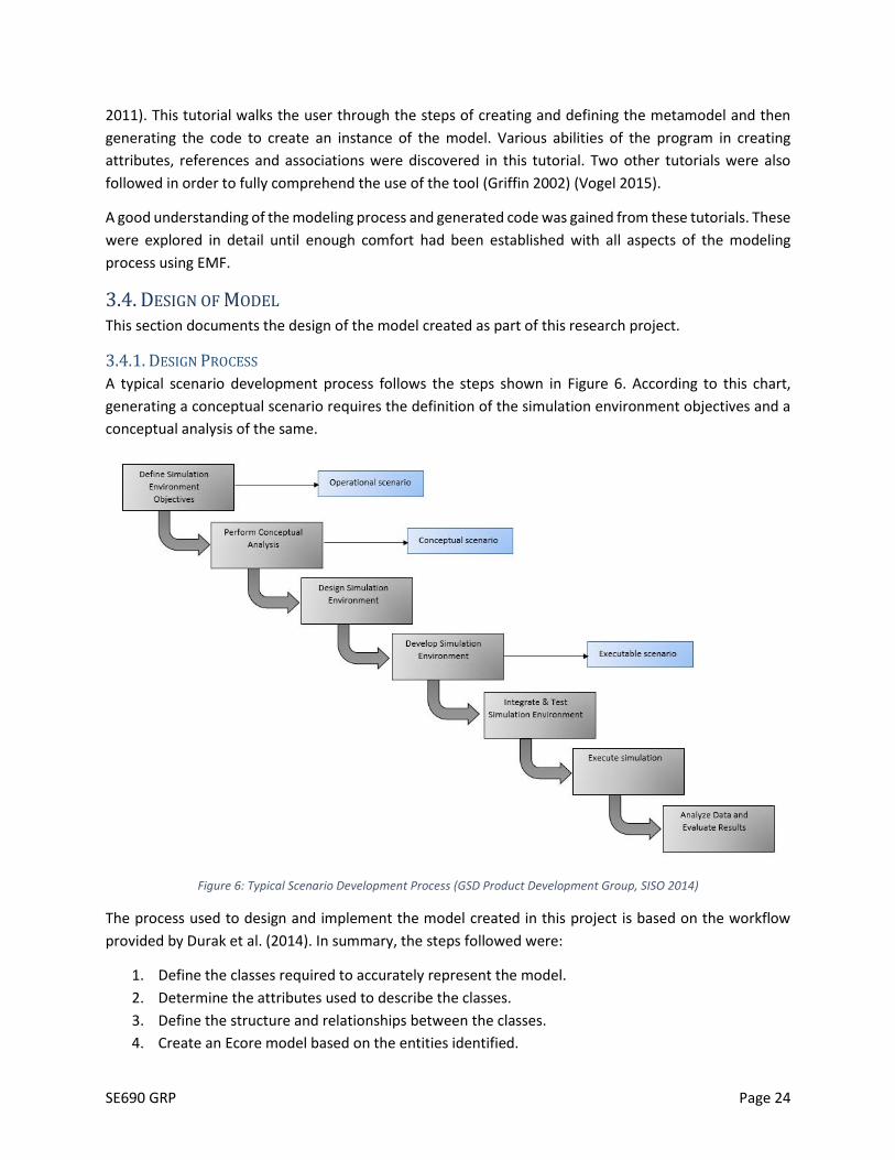
A typical scenario development process follows the steps shown in Figure 6. According to this chart,
generating a conceptual scenario requires the definition of the simulation environment objectives and a
conceptual analysis of the same.
Figure 6: Typical Scenario Development Process (GSD Product Development Group, SISO 2014)
The process used to design and implement the model created in this project is based on the workflow
provided by Durak et al. (2014). In summary, the steps followed were:
1. Define the classes required to accurately represent the model.
2. Determine the attributes used to describe the classes.
3. Define the structure and relationships between the classes.
4. Create an Ecore model based on the entities identified.

SE690 GRP Page 25
5. Integrate this model of aviation entities into the BOM framework constructed by Durak et al.
(2014).
6. Generate Java code for the model.
7. Create a runtime instance and use it to define and edit an aviation scenario.
The framework was developed in two main stages, as follows:
Stage 1: An aviation scenario metamodel was developed in order to capture the necessary
characteristics of a flight. This drew upon the ontology developed in the first part of the project
in order to define these attributes.
Stage 2: The aviation metamodel was integrated with the BOM metamodel in order to define
scenarios with specific aviation-related properties.
The design of the model will be described in the remainder of the section.

SE690 GRP Page 26
3.4.2. CLASS DIAGRAM FOR AVIATION SCENARIO MODEL
The overall class diagram for the aviation-specific entities of the model can be seen in Figure 7 below. This
is only a high-level view and each class has been explained in the section to follow.
Figure 7: Overall Class Diagram of Aviation Entities
3.4.3. CLASS DESCRIPTIONS FOR AVIATION SCENARIO MODEL
A description of each of the classes, their attributes and associations has been described in this section.
3.4.3.1. LANDINGSCENARIO CLASS
LandingScenario is the superclass which contains five subclasses (Figure 8):
NormalLanding
CrosswindLanding
ShortFieldLanding
SoftFieldLanding
UnpreparedFieldLanding

SE690 GRP Page 27
These are the types of landing scenarios that can be handled by the simulation environment. A type is
assigned based on the scenario being executed.
Figure 8: Subclasses which inherit from the LandingScenario class
The LandingScenario class also contains all the other classes that form the aviation domain. This can be
seen in Figure 9.
Figure 9: Classes contained in LandingScenario class
The LandingScenario class contains all others so that an instance created of this class can define the
properties of all other classes and their attributes. It is a collection of pilots, airports, runways, control
towers, flight properties, weather patterns and aircrafts which collectively define all the required
scenarios.
3.4.3.2. AIRCRAFT CLASS
The aircraft class is connected to several other classes and contains various attributes that define its
properties. The basic structure can be seen in Figure 10.

SE690 GRP Page 28
Figure 10: References and Attributes of Aircraft Class
An aircraft has one attribute – its call sign, and has various associations with other classes. It is connected
to two airports – its port of origin and destination. The runway that the aircraft will be landing on is also
specified in the model. At any given point, the properties of the flight and weather are also associated
with the aircraft class. All aircrafts must have a pilot, and are associated with the ATC tower which is
following them at the given time. In addition to these properties, an aircraft also has a state at any given
time. This has been defined in detail in the next section.
3.4.3.3. STATE CLASS
This class has only a single attribute and is connected to the aircraft as can be seen in Figure 11 and Figure
12.
Figure 11: State Class and its Associations in the Model
Figure 12: Properties of State Class
The purpose of this class is to describe the behavior of the aircraft at any given time. A state diagram of
the aircraft during the landing process has been shown in Figure 13.

SE690 GRP Page 29
Figure 13: State Machine Diagram for Aircraft Landing Model
In this case, state change occurs when ATC issues or denies the respective clearance requested by the
pilot. The clearance status is changed by ATC and in response to this clearance, the state of the aircraft is
changed by the pilot to reflect the next action required. The specific state changes for each type of landing
have been discussed in Section 4. Results and Analysis
3.4.3.4. AIRPORT CLASS
The airport class contains one attribute - a string identifier for the airport code. It is also connected to
various (zero or more) aircrafts that are departing from and arriving at it. Each airport has an air traffic
control tower and one or more runways. The model can be seen in Figure 14.
Figure 14: Properties of Airport Class
3.4.3.5. RUNWAY CLASS
A runway has three properties – an identifier that includes its heading, the name of the airport that
operates it, and the length of the runway. This is shown in Figure 15.
Figure 15: Properties of Runway Class

SE690 GRP Page 30
3.4.3.6. ATC CLASS
The ATC class includes the controller who is acting on behalf of the tower, the airport that it is attached
to and the zero to many aircrafts that it is currently monitoring and instructing. These properties can be
seen in Figure 16.
Figure 16: Properties of ATC Class
3.4.3.7. PILOT CLASS
The pilot class consists of the name of the pilot and the aircraft they are associated with, as seen in Figure
17. This class would invoke the method to make changes to the state of the aircraft in response to the
instructions from ATC.
Figure 17: Properties of Pilot Class
3.4.3.8. FLIGHTPROPERTIES CLASS
This class shows the instantaneous properties of the flight. It includes the location as well as the motion
and speed characteristics as shown in Figure 18. The attributes included in this class are the ones which
were defined under the flight properties section of the ontology, which can be found in Table 3.
Figure 18: Properties of FlightProperties Class
3.4.3.9. WEATHER CLASS
This class shows the instantaneous weather conditions around the aircraft. It includes the location in
addition to the various properties shown in Figure 19Figure 18. The attributes included in this class are
the ones which were defined under the weather section of the ontology, which can be found in Table
5Table 3.

SE690 GRP Page 31
Figure 19: Properties of Weather Class
3.4.3.10. SUMMARY OF CLASSES IN AVIATION MODEL
A summary of all the classes, their attributes and the classes they are associated with can be found below
in Table 6.
Table 6: Summary of Class Attributes and Associations for Aviation Scenario Model
Class LandingScenario
Attributes -
Associated Classes All classes below are contained in LandingScenario
Class Aircraft
Attributes callSign
Associated Classes origin: Airport
destination: Airport
Runway
Weather
State
FlightProperties
Pilot
ATC
Class State
Attributes state
Associated Classes Aircraft
Class Airport
Attributes identifier
Associated Classes Aircraft
ATC
Runway
Class Runway
Attributes
identifier
length
Associated Classes Airport
Aircraft
Class ATC

SE690 GRP Page 32
Attributes controllerName
Associated Classes Airport
Aircraft
Class Pilot
Attributes name
Associated Classes Aircraft
Class FlightProperties
Attributes groundspeed
altitude
latitude
longitude
pitch
roll
pitchRate
rollRate
turnRate
flightRules
Associated Classes Aircraft
Class Weather
Attributes temperature
windShear
crossWindComponent
location
dewPoint
visibility
skyCondition
Associated Classes Aircraft
3.4.4. CLASS DIAGRAM FOR BOM INTEGRATION WITH AVIATION ENTITIES
The class diagram for the BOM metamodel defined by Durak et al. can be seen in Figure 20. This has been
used as a framework to define the ASDL model. Some of the main concepts defined in this metamodel
have been described in the following section.

SE690 GRP Page 33
Figure 20: BOM Metamodel used as framework for ASDL (Durak, et al. 2014)
3.4.5. CLASS DESCRIPTIONS FOR BOM CLASSES
This section describes main classes defined for the baseline BOM metamodel.
3.4.5.1. CONCEPTUALSCENARIO CLASS
The ConceptualScenario class is the base class that contains all the other classes in the model. An instance
created of this class can define the properties of all other classes and their attributes. In the integrated
model that includes all BOM and Aviation Domain classes, LandingScenario is also contained within the
ConceptualScenario class. This also includes all other properties, such as other conceptual entities,
patterns of interplay among various entities, a state machine that defines the states of an entity, events
which cause state changes as well as a class listing all the basic attributes of the scenario
(ScenarioIdentification class). This can be seen in Figure 21.

SE690 GRP Page 34
Figure 21: Properties of ConceptualScenario Class
3.4.5.2. SCENARIOIDENTIFICATION CLASS
The ScenarioIdentification class (Figure 22) lists a number of attributes that explain the scenario in terms
of its name, version, description, purpose along with a point of contact and their details. This class is meant
to be for informational purposes.
Figure 22: Properties of ScenarioIdentification Class
3.4.5.3. CONCEPTUALENTITY CLASS
The ConceptualEntity class has a name and characteristics of the entity. It defines all the domain entities
that interact with each other in order to perform actions within the scenario. All the aviation scenario
classes defined in Section 3.4.3. Class Descriptions For Aviation Scenario Model conceptual entities.
Figure 23: Properties of ConceptualEntity Class
3.4.5.4. PATTERNOFINTERPLAY CLASS
The PatternOfInterplay class (Figure 24) provides a mechanism for identifying sequences of pattern
actions (including variations and exceptions) which are necessary for fulfilling a pattern of interplay, which
is being represented by the BOM.

SE690 GRP Page 35
Figure 24: Properties of PatternOfInterplay Class
3.4.5.5. PATTERNACTION CLASS
A PatternAction is a single step in a pattern of interplay that may result in a state change of a conceptual
entity. It has a name, a position in the sequence of the pattern of interplay, a conceptual entity as a sender
and another as a receiver, an event that represents the pattern action as well as related variations and
exceptions. This class identifies a pattern action to be carried out in order to successfully accomplish the
named pattern of interplay that it is a part of. The properties of the class can be seen in Figure 25.
Figure 25: Properties of PatternAction Class
3.4.5.6. STATEMACHINE CLASS
This class provides a mechanism for identifying the different behavior states that are expected to be
exhibited by the conceptual entities. It identifies the state machines including the conceptual entity in
question and the states required for representing the aspects of the conceptual model. This is shown in
Figure 26.
Figure 26: Properties of StateMachine Class
3.4.5.7. EXITCONDITION CLASS
The ExitCondition class (Figure 27) identifies the condition for a state transition. It includes the
identification of the pattern action that causes this change as well as the state which is a result of the
change.
Figure 27: Properties of ExitCondition Class

SE690 GRP Page 36
3.4.5.8. EVENT CLASS
The event class identifies the conceptual events, which may be directed (messages) or undirected
(triggers), which are required for representing the pattern actions associated with a pattern of interplay.
This can be seen in Figure 28.
Figure 28: Properties of Event Class
3.4.5.9. SUMMARY OF CLASSES IN BOM MODEL
A summary of all the classes, their attributes and the classes they are associated with can be found below
in Table 7. This includes the basic single-attribute classes that have not been defined separately.
Table 7: Summary of all Class Attributes and Associations for BOM Model
Class ConceptualScenario
Attributes -
Associated Classes All classes below are contained in ConceptualScenario
Class ScenarioIdentification
Attributes Name
Version
Description
Purpose
ModificationDate
UseHistory
UseLimitations
POCName
POCType
POCOrganization
POCTelephone
POCEmail
Associated Classes -
Class ConceptualEntity
Attributes Name
Associated Classes EntityCharacteristic
Class EntityCharacteristic
Attributes Name
Type
Value

SE690 GRP Page 37
Associated Classes -
Class PatternOfInterplay
Attributes Name
Associated Classes PatternAction
Class PatternAction
Attributes Name
Sequence
Associated Classes senders: ConceptualEntity
receivers: ConceptualEntity
Event
Variation
Exception
Class Event
Attributes Name
Associated Classes
sourceCharacteristic: EntityCharacteristic
targetCharacteristic: EntityCharacteristic
contentCharacteristic: EntityCharacteristic
TriggerCondition
Class TriggerCondition
Attributes Condition
AssociatedClasses -
Class Variation
Attributes Name
Condition
Associated Classes receivers: ConceptualEntity
senders: ConceptualEntity
Class Exception
Attributes Name
Condition
Associated Classes receivers: ConceptualEntity
senders: ConceptualEntity
Class StateMachine
Attributes Name
Associated Classes State
ConceptualEntity
Class ExitCondition
Attributes -
Associated Classes State
PatternAction

SE690 GRP Page 38
3.4.6. INTEGRATED CLASS DIAGRAM
The final metamodel for the project was created by integrating the Aviation Scenario and BOM
metamodels. All the ASDL classes have been contained in the ConceptualEntity class in this metamodel.
Figure 29: Integrated metamodel including ASDL and BOM entities

SE690 GRP Page 39
3.5. SCENARIO GENERATION AND MODEL IMPLEMENTATION The relationship between a conceptual model and a conceptual scenario can be seen in Figure 30. Once a
conceptual model exists, a conceptual scenario is created by executing the model and defining the
attributes of each entity in the instance of the model.
Figure 30: Relationship between conceptual model and conceptual scenario (GSD Product Development Group, SISO 2014)
This was performed by first executing the automatic validation process offered by Eclipse to ensure that
all classes and attributes include specific requirements for the expected data. These standards are defined
within the metamodel and include items such as ensuring that all attributes have a data type, and all class
relationships define the expected cardinality. This just makes sure that a model created of this metamodel
has certain required parameters which can be used to validate the model itself. Then, an EMF Generator
Model was created of the integrated model defined earlier. This Generator Model contains an overview
of all the classes and can be seen in Figure 31.

SE690 GRP Page 40
Figure 31: EMF Generator Model of LandingIntegration Ecore Model
Using EMF’s in-built code generation tools, the model, editing and testing codes were created using the
modeling concepts outlined in Section 3.3.1. Modeling ConceptsThis generated Java classes for all the
conceptual classes containing getter and setter methods for each. A snapshot of this generated code can
be seen in Figure 32.

SE690 GRP Page 41
Figure 32: Generated Java code for model classes
A Java class is created for each class in the conceptual model and includes the getter and setter methods
for all attributes. It also allows for changes to be made in the generation of code for each class based on
the required behavior. The generated classes have not been altered in this project. A snippet of the
Aircraft.java class can be seen in Figure 33.

SE690 GRP Page 42
Figure 33: A snapshot of Aircraft.java code
A runtime instance of Eclipse was then opened to execute the model and create scenarios. Attempting to
create a new project shows the option of creating a LandingIntegration model which can be seen in Figure
34. A class then needs to be selected as the basic Model Object being created. Selecting
ConceptualScenario as the model object (Figure 35) gives us the ability to model all other entities as these
are contained within the ConceptualScenario class. This then allows for all child classes to be defined along
with their properties which would constitute the ConceptualScenario (Figure 36).

SE690 GRP Page 43
Figure 34: Creating a new LandingIntegration Model
Figure 35: Selecting ConceptualScenario as the Base Object

SE690 GRP Page 44
Figure 36: Creating instances of child classes
The attributes can then be entered for each child object as shown in Figure 37. When an object of an
associated class is created, this gives the option to simply select a previously defined object, which can be
seen in Figure 38. If an Airport has already been defined, its identifier appears in a drop-down menu for
destination and origin of an Aircraft and simply needs to be selected from this menu.
Figure 37: Entering the properties of ScenarioIdentification

SE690 GRP Page 45
Figure 38: Filling in associated object values in conceptual scenario
A conceptual scenario is completed once all related objects and attributes have been defined. The next
step is to show that this conceptual model can define the required landing conceptual scenarios, which
has been done in the following section.

SE690 GRP Page 46
4. RESULTS AND ANALYSIS This section will analyze the results of various scenarios that were executed to further verify if the
developed framework is suitable for defining landing scenarios as required.
4.1. SCENARIOS Various types of conceptual landing scenarios were modeled in order to properly test the model created
in this project. A list of these models and their descriptions can be seen in Table 8.
Table 8: Description of Scenarios used for Analysis
Scenario ID Type Description
Ex_Scen_01 Normal Landing This describes a normal landing with a standard pattern of interplay.
Ex_Scen_02 Crosswind
Landing
This describes a crosswind landing where a substantial component of the
wind is perpendicular to the runway centerline.
Ex_Scen_03 Short Field
Landing
This describes a short-field landing where the length of runway available
is shorter than the length of runway required to land comfortably.
Ex_Scen_04 Soft/Unprepared
Field Landing
This describes a landing on a soft or unprepared field.
Ex_Scen_05 Normal Landing
with Holding
This describes a normal landing where the pilot is required to enter into a
holding pattern before landing.
4.1.1 EXAMPLE SCENARIO 1: NORMAL LANDING
This section goes into the details of building a normal landing scenario. Future sections will only describe
the differences in the conceptual scenario, not the particular attributes of each class. Before the process
and pattern of interplay of a normal landing could be modeled, the main entities needed to be defined.
These were done as shown in Figure 39. The values of the attributes can be seen in the figures to follow.
Figure 39: Conceptual Scenario Attributes for Normal Landing

SE690 GRP Page 47
Figure 40: Properties of Conceptual Scenario for Normal Landing
Figure 41: Properties of Scenario Identification for Normal Landing
Figure 42: Properties of Normal Landing Class for Normal Landing
Figure 43: Properties of Aircraft for Normal Landing
Figure 44: Properties of Pilot for Normal Landing

SE690 GRP Page 48
Figure 45: Properties of Airport for Normal Landing
Figure 46: Properties of Runway for Normal Landing
Figure 47: Properties of ATC for Normal Landing
Figure 48: Properties of Flight Properties for Normal Landing
Figure 49: Properties of Weather for Normal Landing

SE690 GRP Page 49
In some cases, values needed to be entered for the identifying attributes and the associated object values
needed to be picked from existing objects. For instance, once an Airport DAB was created, its value could
be picked as the destination of Aircraft ER-1234 as explained in the previous section. In the case of one-
to-one relationships, as is the case with Runway and Airport, creating a Runway and adding an Airport to
it automatically creates the relationship in the Airport class. This can be seen in Figure 50. When Runway
25L was added with Airport DAB, the values in the DAB object changed from Figure 45 to what can be
seen in Figure 51.
Figure 50: New Runway for Airport DAB
Figure 51: Change in Airport Runway details based on creation of new Runway
The Pattern of Interplay of events for a normal landing were then added to the scenario and can be seen
in Figure 52. The State Machine of the Aircraft can be modeled using the diagram shown earlier (Figure
13). The exit conditions for each state are listed in terms of the Pattern Actions above and the state
following it. This can be seen in Figure 53. Once all properties have been defined, the model can be
validated to see that all the required properties have values, which are within the bounds defined.
Validation for this model was completed and can be seen in Figure 54. This only checks that all objects
have values for mandatory properties, and that these values conform to the standards defined in the
metamodel. For example, an Aircraft without an attached Origin or Destination would not pass this
automated validation check.
In this way, the normal landing scenario can be conceptualized using ASDL and the BOM framework to
define the related attributes. Scenarios can also be created for other types of landing as explained in the
following sub-sections.

SE690 GRP Page 50
Figure 52: Pattern of Interplay for Normal Landing
Figure 53: State Machine of the Aircraft for Normal Landing
Figure 54: Validation completed for model

SE690 GRP Page 51
4.1.2. EXAMPLE SCENARIO 2: CROSSWIND LANDING
A crosswind is any wind that has a perpendicular component to the line or direction of travel. A crosswind
landing has to be performed when a substantial component of the wind is perpendicular to the runway
center line. Wind gusts, downdrafts, and wind shear are often part of a crosswind landing. These factors
require a pilot to adjust his approach path, speed, configuration, and technique. For gusty conditions or
wind shear, the pilot needs to increase the approach speed by one half the gust factor, or one half the
reported airspeed loss due to wind shear (Rossier n.d.). In this case, the only differences in the scenario
generation from the one for normal landing are the weather properties and pattern of interplay. The
sequence of steps that need to be followed is the same, but an additional step needs to be added by the
pilot in his approach to the landing. The pattern of interplay needs to have an additional pattern action
for adjusting to the wind conditions. This can be seen in Figure 55 and Figure 56.
Figure 55: High crosswind component in Ex_Scen_02
Figure 56: Change in Pattern of Interplay for Crosswind Landing

SE690 GRP Page 52
4.1.3. EXAMPLE SCENARIO 3: SHORT FIELD LANDING
A short-field landing needs to be performed when the length of the runway is a limiting factor. If the
length of the runway is shorter than that required for the type of aircraft that is landing, short-field landing
techniques may need to be applied. This is usually done by utilizing maximum wing-flap and by using
minimum engine power in order to have a steep approach to the aiming point. Maximum braking needs
to be applied upon touch-down. Once again, this does not change the definition of the original scenario,
only the pattern action for the pilot is different as he needs to account for the shorter runway length when
coming in for landing. This has been shown in Figure 57.
Figure 57: Change in Pattern of Interplay for Short-Field Landing
4.1.4. EXAMPLE SCENARIO 4: SOFT/UNPREPARED FIELD LANDING
This type of landing is performed when the landing area is soft, wet or has ground obstacles such as
furrows or ruts to contend with. The technique for soft/unprepared field landings is to touch down slowly
and keep the nose wheel off the runway for as long as possible and then gently reduce power. This is done
by adding a pattern action for the pilot to consider the field type and execute the correct maneuver, as
seen in Figure 58.

SE690 GRP Page 53
Figure 58: Change in Pattern of Interplay for Soft Field Landing
4.1.5. EXAMPLE SCENARIO 5: NORMAL LANDING WITH HOLDING
A holding pattern is the flight path maintained by an aircraft awaiting permission to land. It is usually a
racetrack pattern that is used to delay an aircraft that has arrived at its destination but cannot land yet.
This has a slight deviation from the regular landing pattern of interplay as well as aircraft state machine
as an undefined waiting period is imposed upon the aircraft until the requisite clearance can be obtained.
The new pattern of interplay and state machine can be seen in Figure 59 and Figure 60 respectively.
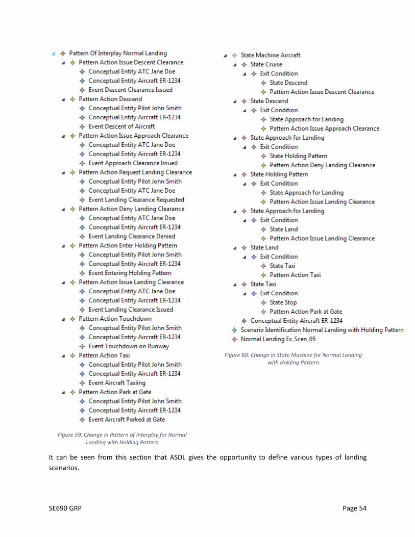
SE690 GRP Page 54
Figure 59: Change in Pattern of Interplay for Normal Landing with Holding Pattern
Figure 60: Change in State Machine for Normal Landing with Holding Pattern
It can be seen from this section that ASDL gives the opportunity to define various types of landing
scenarios.

SE690 GRP Page 55
4.2 VERIFICATION AND VALIDATION Verification of the metamodel was performed by comparing the final model to the initial requirements
defined in the proposal. In this case, the aim of the project was to define the elements of ASDL which can
be used to generate different landing scenarios. Using the metamodel created in this project, five different
types of landing scenarios could be modeled as per specifications and can be reused as required. This was
also confirmed through feedback via Dr. Durak, who observed the functionality of this resulting
metamodel as compared to the metamodel defined in his paper (Durak, et al. 2014).
Validation of the metamodel was conducted by viewing landing scenario videos and checking that the
model was able to define the entire pattern of interplay and the entities involved within them. As all the
data could be expressed using the ASDL concepts, it was established that the metamodel was validated
for its purpose.
5. CONCLUSIONS
5.1. SUMMARY The amount of work being done using flight simulators suggests a need for a common scenario
specification language and process to improve consistency and enable reuse of scenarios. This research
report documents the development of such an Aviation Scenario Definition Language using the BOM
framework to create a scenario generation metamodel for aviation applications. This research focused on
landing as a case study to demonstrate feasibility and use. As the first step, Protégé was used to create
an Ontology of aviation scenario vocabulary. This list of keywords was then used to create a metamodel
of a flight’s landing scenario in EMF. In order to capture the necessary constructs for a simulation scenario,
Simulation Interoperability Standards Organization (SISO) Base Object Model (BOM) was adopted as the
baseline metamodel. The metamodel for ASDL generated using the BOM framework and aviation
keywords was then executed and was able to model five different types of landing scenarios in this case
study. The metamodel developed is thus considered to be effective at the initial stage and can be further
expanded to model other aspects of flight. This can in turn be used to generate executable scenarios using
model transformations. The results of this work will be used to develop a graphical modeling environment
to automatically transform scenario models into executable scenario scripts. The work presented here is
the first stepping stone in formal scenario definition in aviation domain.
5.2. FUTURE WORK The modeling and simulation framework developed as part of this research project is highly extensible.
Some improvements to the model could be the addition of more atmospheric conditions and other
elements encountered by aircrafts. The immediate next step would be to extend the model to account
for takeoff, taxi and cruise states so that the duration of an entire flight can be modeled. This would
expand the number of scenarios that can be generated using the model. The results of this work can be
used to develop a graphical modeling environment to automatically transform scenario models into
executable scenario scripts. The goal in this case would be the recognition of the ASDL as a standardized
language through the Simulation Interoperability Standards Organization (SISO), and its ultimate
deployment in simulators.

SE690 GRP Page 56
6. REFERENCES Alatrish, Emhimed. 2013. "Comparison Some of Ontology Editors." Management Information Systems 8
(2): 018-024.
Bechhofer, Sean. 2009. "OWL: Web Ontology Language." In Encyclopedia of Database Systems, by Ling Liu
and M. Tamer Özsu, 2008-2009. Boston: Springer US.
Durak, Umut, Okan Topcu, Robert Siegfried, and Halit Oguztuzun. 2014. "Scenario Development: A Model-
Driven Engineering Perspective." Simulation and Modeling Methodologies, Technologies and
Applications (SIMULTECH), 2014 International Conference on. IEEE. 117-124.
Eclipse. n.d. Eclipse Modeling Project. https://eclipse.org/modeling/emf/.
Federal Aviation Administration. 2012. AFS Flight Program Flight Operations Manual. Federal Aviation
Administration.
Gauci, J., and D. Zammit-Mangion. 2008. "A Rapid Scenario Generation Tool for Repeatable Simulated
Traffic Conflicts in Flight Simulation." The 26th International Congress of the Aeronautical
Sciences.
Griffin, Catherine. 2002. Using EMF. International Business Machines Corp. (IBM).
GSD Product Development Group, SISO. 2014. Guideline on Scenario Development for Simulation
Environments. Orlando: Simulation Interoperability Standards Organization.
Helming, Jonas, and Maximilian Koegel. 2011. What every Eclipse Developer should know about EMF.
Munich: EclipseSource. Accessed 2015.
Hilera, José, and Luis Fernández-Sanz. 2010. "Developing Domain-ontologies to Improve Sofware
Engineering Knowledge." International Conference on Software Engineering Advances.
Hoisl, Bernard, Stefan Sobernig, and Mark Strembeck. 2014. "Natural-language Scenario Descriptions for
Testing Core Language."
Moroney, William F., and Michael G. Lilienthal. 2008. "Human Factors in Simulation and Training: An
Overview." In Human Factors in Simulation and Training, by Dennis A. Vincenzi, John A. Wise,
Mustapha Mouloua and Peter A. Hancock, 3-38. Boca Raton: CRC Press.
Noy, Natalya F., and Deborah L. McGuinness. 2001. Ontology Development 101: A Guide to Creating Your
First Ontology. Knowledge Systems Laboratory, Stanford University.
Noy, Natalya F., Michael Sintek, Stefan Decker, Monica Crubézy, Ray W. Fergerson, and Mark A. Musen.
2001. "Creating Semantic Web Contents with Protégé-2000." IEEE Intelligent Systems 16 (2): 60-
71.
Oaks, Robert, Shurong Liu, David Zhou, Mike Paglione, and William J. Hughes. 2003. "Methodology for the
generation of air traffic scenarios based on recorded traffic data." Digital Avionics Systems
Conference (DASC). Indianapolis: IEEE. 5-C.

SE690 GRP Page 57
n.d. Protégé Home Page. http://protege.stanford.edu/.
Rossier, Robert N. n.d. Crosswind landing - Flight Training. Accessed February 23, 2016.
http://flighttraining.aopa.org/students/solo/skills/crosswind.html.
SESAR. n.d. EUROCONTROL ATM Lexicon. Single European Sky ATM Research.
Shannon, Robert E. 1975. Systems simulation; the art and science. Englewood Cliffs: Prentice Hall, 723-
724.
Signor, David, Paul Davis, Sandra Lozito, Anthony Andre, Doug Sweet, and Erin Wallace. 2004. "Efficient
Air Traffic Scenario Generation." AIAA 4th Aviation Technology, Integration and Operations (ATIO)
Forum. Chicago.
Sinlapakun, Sakon, and Yachai Limpiyakorn. 2013. "Domain Specific Language for Collaborative
Determination of Separation Minima between Aircrafts." International Journal of Software
Engineering and its Applications 399-414.
Vogel, Lars. 2015. Eclipse Modeling Framework (EMF) - Tutorial. vogella GmbH.
Yao, Zhong, and Quan Zhang. 2009. "Protégé-Based Ontology Knowledge Representation for MIS Courses
." International Conference on Web Information Systems and Mining.

SE690 GRP Page 58
APPENDICES
APPENDIX A: DEFINITIONS IN ONTOLOGY TERM Definition
ACTUAL
CALCULATED
LANDING
TIME
ACLT is a flight’s frozen calculated landing time. An actual time determined at freeze
calculated landing time (FCLT) or meter list display interval (MLDI) for the adapted
vertex for each arrival aircraft based upon runway configuration, airport acceptance
rate, airport arrival delay period, and other metered arrival aircraft. This time is
either the vertex time of arrival (VTA) of the aircraft or the tentative calculated
landing time (TCLT)/ACLT of the previous aircraft plus the arrival aircraft interval
(AAI), whichever is later. This time will not be updated in response to the aircraft’s
progress.
AERODROME
ELEVATION The elevation of the highest point of the landing area.
AIR TRAFFIC All aircraft in flight or operating on the maneuvering area of an aerodrome.
AIR TRAFFIC
CONTROL
A service operated by appropriate authority to promote the safe, orderly and
expeditious flow of air traffic.
AIR TRAFFIC
CONTROL
CLEARANCE
Authorization for an aircraft to proceed under conditions specified by an air traffic
control unit.
Note 1: For convenience, the term air traffic control clearance is frequently
abbreviated to clearance when used in appropriate contexts.
Note 2: The abbreviated term clearance may be prefixed by the words taxi, takeoff,
departure, en route, approach or landing to indicate the particular portion of flight
to which the air traffic control clearance relates.
AIRBORNE An aircraft is considered airborne when all parts of the aircraft are off the ground.
AIRCRAFT
Any machine that can derive support in the atmosphere from the reactions of the air
other than the reactions of the air against the earth’s surface.
AIRCRAFT
APPROACH
CATEGORY
A grouping of aircraft based on a speed of 1.3 times the stall speed in the landing
configuration at maximum gross landing weight. An aircraft must fit in only one
category. If it is necessary to maneuver at speeds in excess of the upper limit of a
speed range for a category, the minimums for the category for that speed must be
used. For example, an aircraft which falls in Category A, but is circling to land at a
speed in excess of 91 knots, must use the approach Category B minimums when
circling to land. The categories are as follows:
a. Category A− Speed less than 91 knots.
b. Category B− Speed 91 knots or more but less than 121 knots.
c. Category C− Speed 121 knots or more but less than 141 knots.

SE690 GRP Page 59
d. Category D− Speed 141 knots or more but less than 166 knots.
e. Category E− Speed 166 knots or more.
AIRCRAFT
CLASSES
For the purposes of Wake Turbulence Separation Minima, ATC classifies aircraft as
Heavy, Large, and Small as follows:
a. Heavy− Aircraft capable of takeoff weights of 300,000 pounds or more whether or
not they are operating at this weight during a particular phase of flight.
b. Large− Aircraft of more than 41,000 pounds, maximum certificated takeoff
weight, up to but not including 300,000 pounds.
c. Small− Aircraft of 41,000 pounds or less maximum certificated takeoff weight.
AIRCRAFT
CONFLICT
Predicted conflict, within URET, of two aircraft, or between aircraft and airspace. A
Red alert is used for conflicts when the predicted minimum separation is 5 nautical
miles or less. A Yellow alert is used when the predicted minimum separation is
between 5 and approximately 12 nautical miles. A Blue alert is used for conflicts
between an aircraft and predefined airspace.
AIRPORT
An area on land or water that is used or intended to be used for the landing and
takeoff of aircraft and includes its buildings and facilities, if any.
AIRPORT
ELEVATION
The highest point of an airport’s usable runways measured in feet from mean sea
level.
AIRSPEED
The speed of an aircraft relative to its surrounding air mass. The unqualified term
“airspeed” means one of the following:
a. Indicated Airspeed− The speed shown on the aircraft airspeed indicator. This is
the speed used in pilot/controller communications under the general term
“airspeed.” (Refer to 14 CFR Part 1.)
b. True Airspeed− The airspeed of an aircraft relative to undisturbed air. Used
primarily in flight planning and en route portion of flight. When used in
pilot/controller communications, it is referred to as “true airspeed” and not
shortened to “airspeed.”
ALTERNATE
AERODROME
An aerodrome to which an aircraft may proceed when it becomes either impossible
or inadvisable to proceed to or to land at the aerodrome of intended landing.
ALTITUDE
The vertical distance of a level, a point or an object considered as a point, measured
from mean sea level (MSL).
APPROACH
CLEARANCE
Authorization by ATC for a pilot to conduct an instrument approach. The type of
instrument approach for which a clearance and other pertinent information is
provided in the approach clearance when required.

SE690 GRP Page 60
APPROACH
SPEED
The recommended speed contained in aircraft manuals used by pilots when making
an approach to landing. This speed will vary for different segments of an approach as
well as for aircraft weight and configuration.
ARRIVAL
CENTER The ARTCC having jurisdiction for the impacted airport.
ARRIVAL TIME The time an aircraft touches down on arrival.
CALCULATED
LANDING
TIME
A term that may be used in place of tentative or actual calculated landing time,
whichever applies.
CLEARED
APPROACH
ATC authorization for an aircraft to execute any standard or special instrument
approach procedure for that airport. Normally, an aircraft will be cleared for a
specific instrument approach procedure.
CLEARED FOR
TAKEOFF
ATC authorization for an aircraft to depart. It is predicated on known traffic and
known physical airport conditions.
CLEARED
THROUGH
ATC authorization for an aircraft to make intermediate stops at specified airports
without refiling a flight plan while en route to the clearance limit.
CLEARED TO
LAND
ATC authorization for an aircraft to land. It is predicated on known traffic and known
physical airport conditions.
CONTROLLER A person authorized to provide air traffic control services.
COORDINATE
S
The intersection of lines of reference, usually expressed in degrees/minutes/seconds
of latitude and longitude, used to determine position or location.
CROSSWIND
a. When used concerning the traffic pattern, the word means “crosswind leg.” (See
TRAFFIC PATTERN.)
b. When used concerning wind conditions, the word means a wind not parallel to
the runway or the path of an aircraft.
CROSSWIND
COMPONENT
The wind component measured in knots at 90 degrees to the longitudinal axis of the
runway.
CRUISING
ALTITUDE
An altitude or flight level maintained during en route level flight. This is a constant
altitude and should not be confused with a cruise clearance.
FINAL
APPROACH
That part of an instrument approach procedure which commences at the specified
final approach fix or point, or where such a fix or point is not specified.

SE690 GRP Page 61
FLIGHT LEVEL
A level of constant atmospheric pressure related to a reference datum of 29.92
inches of mercury. Each is stated in three digits that represent hundreds of feet. For
example, flight level (FL) 250 represents a barometric altimeter indication of 25,000
feet; FL 255, an indication of 25,500 feet.
FREEZE
CALCULATED
LANDING
TIME
A dynamic parameter number of minutes prior to the meter fix calculated time of
arrival for each aircraft when the TCLT is frozen and becomes an ACLT (i.e., the VTA
is updated and consequently the TCLT is modified as appropriate until FCLT minutes
prior to meter fix calculated time of arrival, at which time updating is suspended and
an ACLT and a frozen meter fix crossing time (MFT) is assigned).
FUEL
REMAINING
A phrase used by either pilots or controllers when relating to the fuel remaining on
board until actual fuel exhaustion. When transmitting such information in response
to either a controller question or pilot initiated cautionary advisory to air traffic
control, pilots will state the APPROXIMATE NUMBER OF MINUTES the flight can
continue with the fuel remaining. All reserve fuel SHOULD BE INCLUDED in the time
stated, as should an allowance for established fuel gauge system error.
GROUND
SPEED The speed of an aircraft relative to the surface of the earth.
HOLD
PROCEDURE
A predetermined maneuver which keeps aircraft within a specified airspace while
awaiting further clearance from air traffic control. Also used during ground
operations to keep aircraft within a specified area or at a specified point while
awaiting further clearance from air traffic control.
IFR
CONDITIONS Weather conditions below the minimum for flight under visual flight rules.
INSTRUMENT
APPROACH
OPERATIONS
An approach and landing using instruments for navigation guidance based on an
instrument approach procedure. There are two methods for executing instrument
approach operations:
a. A two−dimensional (2D) instrument approach operation, using lateral navigation
guidance only; and
b. A three−dimensional (3D) instrument approach operation, using both lateral and
vertical navigation guidance.

SE690 GRP Page 62
INSTRUMENT
APPROACH
PROCEDURE
A series of predetermined maneuvers by reference to flight instruments with
specified protection from obstacles from the initial approach fix, or where
applicable, from the beginning of a defined arrival route to a point from which a
landing can be completed and thereafter, if a landing is not completed, to a position
at which holding or en route obstacle clearance criteria apply.
INSTRUMENT
FLIGHT RULES
A set of rules governing the conduct of flight under instrument meteorological
conditions.
INSTRUMENT
LANDING
SYSTEM
A precision instrument approach system which normally consists of the following
electronic components and visual aids:
a. Localizer.
b. Glideslope.
c. Outer Marker.
d. Middle Marker.
e. Approach Lights.
LANDING
AREA That part of a movement area intended for the landing or take-off of aircraft.
LANDING
DIRECTION
INDICATOR
A device which visually indicates the direction in which landings and takeoffs should
be made.
LANDING
DISTANCE
AVAILABLE
The length of runway which is declared available and suitable for the ground run of
an airplane landing.
LANDING
MINIMUMS
The minimum visibility prescribed for landing a civil aircraft while using an
instrument approach procedure. The minimum applies with other limitations set
forth in 14 CFR Part 91 with respect to the Minimum Descent Altitude (MDA) or
Decision Height (DH) prescribed in the instrument approach procedures as follows:
a. Straight-in landing minimums. A statement of MDA and visibility, or DH and
visibility, required for a straight-in landing on a specified runway, or
b. Circling minimums. A statement of MDA and visibility required for the circle-to-
land maneuver.
LANDING
ROLL
The distance from the point of touchdown to the point where the aircraft can be
brought to a stop or exit the runway.
LANDING
SEQUENCE The order in which aircraft are positioned for landing.
MISSED
APPROACH a. A maneuver conducted by a pilot when an instrument approach cannot be
completed to a landing. The route of flight and altitude are shown on instrument

SE690 GRP Page 63
approach procedure charts. A pilot executing a missed approach prior to the Missed
Approach Point (MAP) must continue along the final approach to the MAP.
b. A term used by the pilot to inform ATC that he/she is executing the missed
approach.
c. At locations where ATC radar service is provided, the pilot should conform to
radar vectors when provided by ATC in lieu of the published missed approach
procedure.
NATIONAL
AIRSPACE
SYSTEM
The common network of U.S. airspace; air navigation facilities, equipment and
services, airports or landing areas; aeronautical charts, information and services;
rules, regulations and procedures, technical information, and manpower and
material. Included are system components shared jointly with the military.
PRECISION
APPROACH
PROCEDURE
A standard instrument approach procedure in which an electronic glideslope/or
other type of glidepath is provided; e.g., ILS, PAR, and GLS.
RADIO
ALTIMETER
Aircraft equipment which makes use of the reflection of radio waves from the
ground to determine the height of the aircraft above the surface.
RADIO
MAGNETIC
INDICATOR
An aircraft navigational instrument coupled with a gyro compass or similar compass
that indicates the direction of a selected NAVAID and indicates bearing with respect
to the heading of the aircraft.
RNAV
APPROACH
An instrument approach procedure which relies on aircraft area navigation
equipment for navigational guidance.
RUNWAY
A defined rectangular area on a land aerodrome prepared for the landing and take-
off of aircraft.
RUNWAY
HEADING
The magnetic direction that corresponds with the runway centerline extended, not
the painted runway number. When cleared to “fly or maintain runway heading,”
pilots are expected to fly or maintain the heading that corresponds with the
extended centerline of the departure runway. Drift correction shall not be applied;
e.g., Runway 4, actual magnetic heading of the runway centerline 044, fly 044.
RUNWAY IN
USE/ACTIVE
RUNWAY/DU
TY RUNWAY
Any runway or runways currently being used for takeoff or landing. When multiple
runways are used, they are all considered active runways. In the metering sense, a
selectable adapted item which specifies the landing runway configuration or
direction of traffic flow. The adapted optimum flight plan from each transition fix to
the vertex is determined by the runway configuration for arrival metering processing
purposes.
SEGMENTS OF
AN
An instrument approach procedure may have as many as four separate segments
depending on how the approach procedure is structured.

SE690 GRP Page 64
INSTRUMENT
APPROACH
PROCEDURE
a. Initial Approach− The segment between the initial approach fix and the
intermediate fix or the point where the aircraft is established on the intermediate
course or final approach course. (See ICAO term INITIAL APPROACH SEGMENT.)
b. Intermediate Approach− The segment between the intermediate fix or point and
the final approach fix. (See ICAO term INTERMEDIATE APPROACH SEGMENT.)
c. Final Approach− The segment between the final approach fix or point and the
runway, airport, or missed approach point. (See ICAO term FINAL APPROACH
SEGMENT.)
d. Missed Approach− The segment between the missed approach point or the point
of arrival at decision height and the missed approach fix at the prescribed altitude.
STOP AND GO
A procedure wherein an aircraft will land, make a complete stop on the runway, and
then commence a takeoff from that point.
STRAIGHT-IN
LANDING
A landing made on a runway aligned within 30o of the final approach course
following completion of an instrument approach.
SURVEILLANC
E APPROACH
An instrument approach wherein the air traffic controller issues instructions, for
pilot compliance, based on aircraft position in relation to the final approach course
(azimuth), and the distance (range) from the end of the runway as displayed on the
controller’s radar scope. The controller will provide recommended altitudes on final
approach if requested by the pilot.
TAILWIND
Any wind more than 90 degrees to the longitudinal axis of the runway. The magnetic
direction of the runway shall be used as the basis for determining the longitudinal
axis.
TAXI The movement of an airplane under its own power on the surface of an airport.
TENTATIVE
CALCULATED
LANDING
TIME
A projected time calculated for adapted vertex for each arrival aircraft based upon
runway configuration, airport acceptance rate, airport arrival delay period, and
other metered arrival aircraft. This time is either the VTA of the aircraft or the
TCLT/ACLT of the previous aircraft plus the AAI, whichever is later. This time will be
updated in response to an aircraft’s progress and its current relationship to other
arrivals.
TOTAL
ESTIMATED
ELAPSED TIME
[ICAO]
For IFR flights, the estimated time required from take-off to arrive over that
designated point, defined by reference to navigation aids, from which it is intended
that an instrument approach procedure will be commenced, or, if no navigation aid
is associated with the destination aerodrome, to arrive over the destination
aerodrome. For VFR flights, the estimated time required from take-off to arrive over
the destination aerodrome.

SE690 GRP Page 65
TOUCH-AND-
GO
An operation by an aircraft that lands and departs on a runway without stopping or
exiting the runway.
TOUCHDOWN The point where the nominal glide path intercepts the runway.
TOUCHDOWN
ZONE
The portion of a runway, beyond the threshold, where it is intended landing aircraft
first contact the runway.
TRAFFIC
A term used by a controller to transfer radar identification of an aircraft to another
controller for the purpose of coordinating separation action.
USER
REQUEST
EVALUATION
TOOL (URET)
User Request Evaluation Tool is an automated tool provided at each Radar Associate
position in selected En Route facilities. This tool utilizes flight and radar data to
determine present and future trajectories for all active and proposal aircraft and
provides enhanced, automated flight data management.
VFR AIRCRAFT An aircraft conducting flight in accordance with visual flight rules.
VFR
CONDITIONS
Weather conditions equal to or better than the minimum for flight under visual flight
rules.
VISIBILITY
The ability, as determined by atmospheric conditions and expressed in units of
distance, to see and identify prominent unlighted objects by day and prominent
lighted objects by night.
a. Flight Visibility−The visibility forward from the cockpit of an aircraft in flight.
b. Ground Visibility−The visibility at an aerodrome as reported by an accredited
observer.
c. Runway Visual Range [RVR] −The range over which the pilot of an aircraft on the
centerline of a runway can see the runway surface markings or the lights delineating
the runway or identifying its centerline.
VISUAL
APPROACH
An approach by an IFR flight when either part or all of an instrument approach
procedure is not completed and the approach is executed in visual reference to
terrain.
WAKE
TURBULENCE
Phenomena resulting from the passage of an aircraft through the atmosphere. The
term includes vortices, thrust stream turbulence, jet blast, jet wash, propeller wash,
and rotor wash both on the ground and in the air.
WIND SHEAR
A change in wind speed and/or wind direction in a short distance resulting in a
tearing or shearing effect. It can exist in a horizontal or vertical direction and
occasionally in both

SE690 GRP Page 66
APPENDIX B: ATC COMMUNICATION PHRASEOLOGY Keyword Use Reference
ABORT To terminate a preplanned aircraft maneuver; e.g., an aborted takeoff.
ACKNOWLEDGE Let me know that you have received and understood this message.
AFFIRMATIVE Yes. UM4
ALERT
A notification to a position that there is an aircraft-to-aircraft or aircraft-to-
airspace conflict, as detected by Automated Problem Detection (APD).
ATC SERVICE
TERMINATED
Advisory that the aircraft is entering airspace in which no air traffic control
service is provided. UM191
CANCEL
EMERGENCY Indication that the urgent or emergency situation is cancelled. DM58
CLEARED
APPROACH
ATC authorization for an aircraft to execute any standard or special
instrument approach procedure for that airport. Normally, an aircraft will be
cleared for a specific instrument approach procedure.
CLEARED FOR
TAKEOFF
ATC authorization for an aircraft to depart. It is predicated on known traffic
and known physical airport conditions.
CLEARED THROUGH
ATC authorization for an aircraft to make intermediate stops at specified
airports without refiling a flight plan while en route to the clearance limit.
CLEARED TO LAND
ATC authorization for an aircraft to land. It is predicated on known traffic and
known physical airport conditions.
CONFIRM REQUEST
Request to confirm the referenced request since the initial request was not
understood. The request should be clarified and resubmitted. UM143
CONFIRM SQUAWK
CODE Request to confirm the selected SSR code. UM144
DESCENT AT
[vertical rate] Instruction to descend at the specified rate. UM343
DESCEND TO [level]
Instruction that a descent to the specified level or vertical range is to
commence and once reached is to be maintained. UM23
ERROR [error
informationR] System-generated notification of an error. UM159R

SE690 GRP Page 67
EXPEDITE
Instruction to execute the associated instruction at the aircraft's best
performance rate. UM245
FLY HEADING
[degrees] Instruction to fly the specified heading. UM190
FUEL REMAINING
A phrase used by either pilots or controllers when relating to the fuel
remaining on board until actual fuel exhaustion. When transmitting such
information in response to either a controller question or pilot initiated
cautionary advisory to air traffic control, pilots will state the APPROXIMATE
NUMBER OF MINUTES the flight can continue with the fuel remaining. All
reserve fuel SHOULD BE INCLUDED in the time stated, as should an allowance
for established fuel gauge system error.
HAZARDOUS
WEATHER [hzwx
specification]
Advisory that the specified hazardous weather information is available for
retrieval. UM269
HOLD POSITION Instruction to hold the current position. UM311
IMMEDIATELY
Instruction to immediately comply with the associated instruction to avoid an
imminent situation. UM230
LANDING REPORT Report indicating that the aircraft has landed. DM102
MAYDAY
MAYDAY
MAYDAY Indication of an emergency situation. DM56
NEGATIVE “No” or “Permission not granted” or “That is not correct.” UM5
REQUEST FULL
ROUTE CLEARANCE
Used by pilots to request that the entire route of flight be read verbatim in an
ATC clearance. Such request should be made to preclude receiving an ATC
clearance based on the original filed flight plan when a filed IFR flight plan has
been revised by the pilot, company, or operations prior to departure.
RESUME OWN
NAVIGATION
Instruction to resume own navigation following a period of tracking or
heading clearances. UM72
REQUEST [level] Request to fly at the specified level or vertical range. DM6
ROGER Indication that the message has been received. DM3
SQUAWK Instruction to select the specified SSR code. UM123
STANDBY Indication that the message will be responded to shortly. DM2

SE690 GRP Page 68
STOP SQUAWK Instruction to disable SSR transponder responses. UM124
UNABLE Indication that the instruction cannot be complied with. DM1
WHEN ABLE
Indication that the associated instruction is executed by the flight crew when
able. UM246
WILCO Indication that the instruction is understood and will be complied with. DM0