Forestry Mobile truck Agriculture MAteriAl HAndling OPTIMUMTM · 64, 72, 79 LPM @ 1000 RPM)...
6
MINING FORESTRY MOBILE TRUCK AGRICULTURE MATERIAL HANDLING Muncie Power Products’ OPTIMUM TM Series gear pumps/motors offer premier performance for a wide variety of applications across several industries. Featuring the innovative OPTI-Grip TM technology, the OPTIMUM TM Series exemplifies strength, endurance and rigidity making for long lasting units even in the most extreme conditions. The W Series is the smallest range of the OPTIMUM TM Series fleet, providing 8 displacements to cover a full range of lower flow, higher pressure requirements. OPTIMUM TM
Transcript of Forestry Mobile truck Agriculture MAteriAl HAndling OPTIMUMTM · 64, 72, 79 LPM @ 1000 RPM)...

MiningForestryMobile truckAgricultureMAteriAl HAndling
Muncie Power Products’ OPTIMUMTM Series gear pumps/motors offer premier
performance for a wide variety of applications across several industries. Featuring
the innovative OPTI-GripTM technology, the OPTIMUMTM Series exemplifies strength,
endurance and rigidity making for long lasting units even in the most extreme
conditions. The W Series is the smallest range of the OPTIMUMTM Series fleet,
providing 8 displacements to cover a full range of lower flow, higher pressure requirements.
OPTIMUMTM
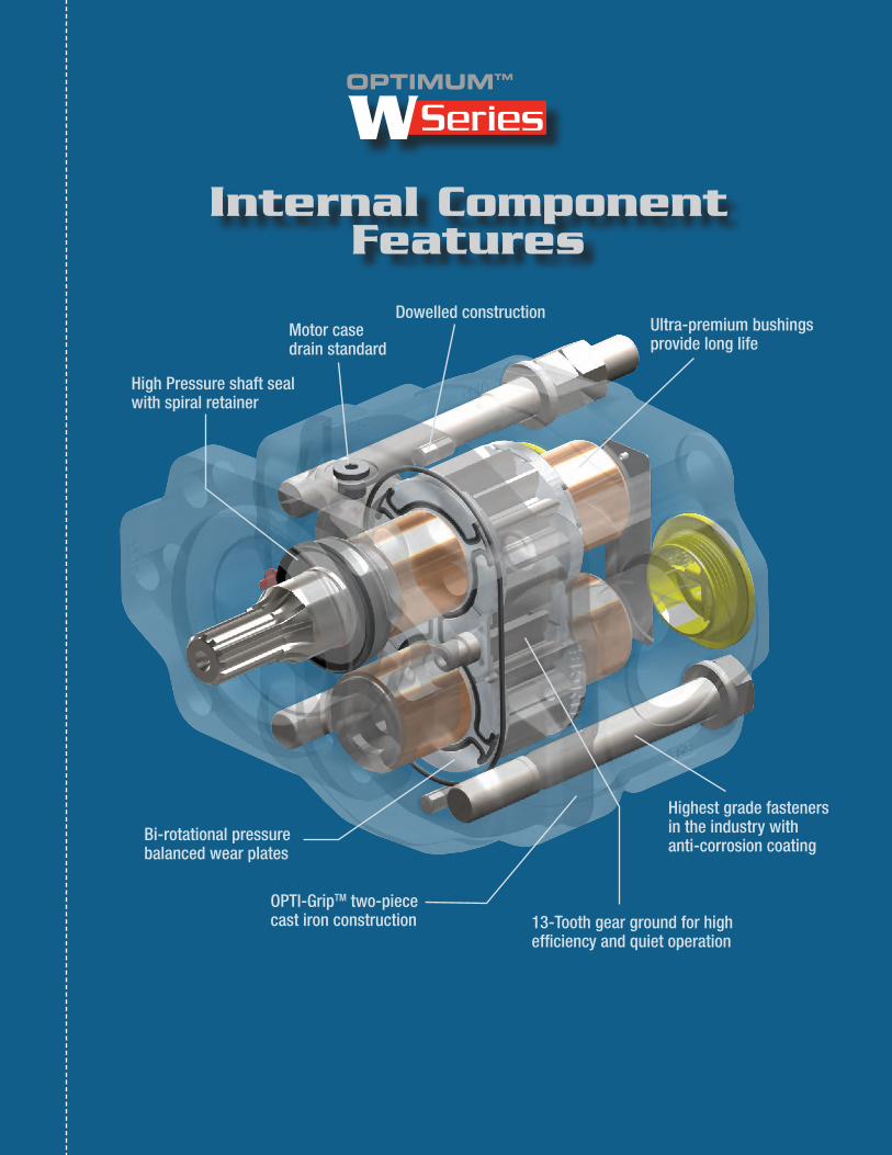
Internal Component Features
High Pressure shaft seal with spiral retainer
Bi-rotational pressure balanced wear plates
Motor case drain standard
Dowelled constructionUltra-premium bushings provide long life
13-Tooth gear ground for high efficiency and quiet operation
Highest grade fasteners in the industry with anti-corrosion coating
OPTI-GripTM two-piece cast iron construction
OPTIMUMTM

W Series Performance Specs
Model NuMber CoNstruCtioN
8 Pump displacements Available• 06, 08, 11, 13, 15, 17, 19, 21 GPM
@ 1000 RPM (23, 30, 42, 49, 57, 64, 72, 79 LPM @ 1000 RPM)
oPti-griptM (Patent Pending) design• 2 piece, pressure holding
construction delivers enhanced structural integrity to achieve higher pressures and superior performance
long life, High Performance bushings• Ultra-premium bushings last
up to 30% longer than typical DUTM style bushings providing greater pump endurance in any application
noise reducing, quiet design• 13 tooth gear design reduces the
noise producing pressure ripple caused per gear tooth
bi-rotational, 4 Port design standard (sAe straight thread only)• SAE ports on the side and rear
of the pump allow plumbing flexibility for user friendly installations
• Bi-rotational, 4 port design allows for pump or motor capabilities and reduces inventory requirements
Pressures up to 4350 Psi (300 bAr)• High pressure capabilities
coupled with an innovative, rugged design make the Optimum Series a long lasting, top performer in all types of applications.
speeds up to 3600 rPM• A wide range of speeds from
600-3600 RPM cover a broad range of application needs while still providing long product life
High Quality, tested design• Tight tolerances in a highly
engineered design result in high pump efficiencies and long lasting performance
• All pumps are 100% tested to ensure expected performance prior to shipment.
Additional Features & Benefits• 5 different shaft options and 3
different mounting flange options provide flexibility when connecting to your power source.
• Bi-Rotational or Uni-Rotational Design
• SAE straight thread or split flange porting available
• Pressure balanced wear-plates standard
• Pump or Motor capability
• High temperature/High pressure shaft seals
• Buna N Body & Thrust Plate seals
• High strength cast iron housings
• Tandem and Triple capabilities
FeaturesSeries: W
GPM (LPM) @ 1000 RPM:06 (23), 08 (30), 11 (42), 13 (49),15 (57), 17 (64), 19 (72), 21 (79)
Shaft Size & Type (metric info where applicable): 01 - SAE “BB” 1.0”rnd shaft w/ 1/4 key
(25.4rnd w/ 6.35 key)02 - SAE “B” 7/8”-13T spline09 - SAE “B” 7/8” rnd shaft w/ 1/4 key
(22.2rnd w/ 6.35 key)16 - 3/4”-11T spline17 - SAE “BB” 1.0”-15T spline
Mounting Flange & Type:A - SAE “A” 2 BoltB - SAE “B” 2/4 BoltR - Remote Foot Mount
Mounting Flange configuration*:Bi-rotational internals (pump or motor)
J0 - bi-rot, w/o O.B. Bearing, w/ 1/4” SAE drain(use w/ splined shafts)
J1 - bi-rot, w/ O.B. Bearing, w/ 1/4” SAE drain(use w/ round shafts)
Uni-rotational internals (pump or motor)***K0 - CW w/o O.B. Bearing, w/ 1/4” SAE drain
(use w/ splined shafts)K1 - CCW w/o O.B. Bearing, w/ 1/4” SAE drain
(use w/ splined shafts)K2 - CW w/ O.B. Bearing, w/ 1/4” SAE drain
(use w/ round shafts)K3 - CCW w/ O.B. Bearing, w/ 1/4” SAE drain
(use w/ round shafts)
Side Ports, 2nd unit:See “side ports, 1st section” below
GPM (LPM) @ 1000RPM, 2nd unit:See values for single unit at left
Thru Drive (multiple units only):T0 - No thru portsT1 - CW thru port configuration (inlet port)T2 - CCW thru port configuration (inlet port)
Assembly Sections:4 - Single unit, with extended studs5 - Tandem unit, with extended studs6 - Triple unit, with extended studs
Design Number: 1
Additional Attributes:A - High pressure shaft seal**
Rear Ports, Size & Type:SAE Ports
GI - SAE-16 x SAE-16 (W06-W11)GT - SAE-20 x SAE-20 (W13 & larger)
Split Flange PortsXX - No rear ports
Side Ports, 1st section:SAE Ports
GI - SAE-16 x SAE-16 (W06-W11)GT - SAE-20 x SAE-20 (W13 & larger)
Split Flange PortsIV - 1.50” SF x 1.00” SF (W06-W13)JC - 2.00” SF x 1.25” SF (W15 & larger)
W 11-02 B J0-GI GI-A 1 5-T2-11 GI
* It is recommended that pumps or motors with a round output shaft use an outboard bearing to assist with radial loads. ** 150 PSI MAX back-pressure *** Uni-rotational internals (K configuration codes) are used with split flange ports only
For Multiple Units Only. Delete for single units and repeat for triple units.
modelDisp.
in3 (cc)maXrPm
mInrPm
maX Pres.PSI (Bar)
Ports (ODt)Side & rear
Ports (SF)Side Only
approx. Wt.Lbs. (Kg)
W06 1.45(23.9) 3,600 800 4,350 (300) -16 1.50” x 1.00” 40.8 (18.5)
W08 1.96(32.2) 3,600 600 4,350 (300) -16 1.50” x 1.00” 42.7 (19.4)
W11 2.42(39.7) 3,250 600 4,350 (300) -16 1.50” x 1.00” 44.0 (19.9)
W13 2.92(47.9) 3,000 600 4,000 (275) -20 1.50” x 1.00” 44.9 (20.4)
W15 3.46(56.8) 2,750 600 3,750 (260) -20 2.0” x 1.25” 47.2 (21.4)
W17 3.96(65.0) 2,500 600 3,500 (240) -20 2.0” x 1.25” 48.7 (22.1)
W19 4.37(71.6) 2,500 600 3,250 (225) -20 2.0” x 1.25” 49.5 (22.4)
W21 4.87(79.8) 2,500 600 3,000 (210) -20 2.0” x 1.25” 50.7 (23.0)
Notes:• MAX RPM is shown at 0 in.hg. and with an appropriately
sized inlet hose• MAX motor back pressure is not to exceed 150PSI
(10BAR) • MAX inlet vacuum is not to exceed 5in.hg. (0.17BAR)• Weights shown are for single, direct mount pumps
• Porting shown is standard pump porting, other porting con-figurations are available
• Motor applications will require a case drain to be plumbed directly back to the reservoir due to excessive return line pressures or surges
The 3-D diamond-like design appearing on Muncie’s hydraulic pumps is a trademark of Muncie Power Products, Inc., Muncie, Indiana (USA), registered in the United States and various foreign countries.

diMeNsioNal drawiNgs
mODeL DIm. a DIm. B
W06 6.59 [167.5] 3.37 [85.5]
W08 6.83 [173.5] 3.60 [91.5]
W11 7.05 [179.0] 3.82 [97.0]
W13 7.28 [185.0] 4.06 [103.0]
W15 7.54 [191.5] 4.31 [109.5]
W17 7.78 [197.5] 4.55 [115.5]
W19 7.97 [202.5] 4.74 [120.5]
W21 8.21 [208.5] 4.98 [126.5]
SAE “B” 2/4 Bolt Mounting Flange Shown
Front View6.88 [174.8]
5.75 [146.1]
Ø0.56 [14.2] 6 Places
3.54 [89.8] SQ.
6.44 [163.6]
Rear View6.46 [164.0]
3.43 [87.0] SQ.
SAE “A” 2 Bolt Mounting FlangeShown with 3/4” - 11T spline shaft
Ø3.25[82.6]
Pilot Dia.
5.13 [130.4]4.19 [106.4]
2.09[53.2]
ø0.44[ø11.1]
2 places
3.23[82.0]
-4 SAE case drain port7/16”-20
UNC thread
5/16”-18 UNC, 2 places holes to be used for
front cover removal
0.98[24.9]
1.50[38.2]
1.10[27.9]
1/2”-13 UNC Thread
2 places
ø0.56[ø14.2]2 places
Muncie’s Remote Mount “R” Mounting FlangeShown with SAE “B” 7/8” round shaft
3.46 [88.0] 1.38[35.1]
6.40[162.5]
4.35[110.5]
3.00 [76.2]4.80 [122.0]
1.81 [46.0]
0.12 [3.0]
0.38 [9.7]
1.25[31.8]
0.41[10.4]
0.94[23.9]
1.00[25.4]
SHAFT CODE 01sae “bb” 1.0” rd. shaft with 1/4” keyNOTE: SAE “B” pilot shown
1.62 [41.1]
0.38[9.7]
1.00[25.4]
0.12[3.0]
0.19[4.8]
0.94 [23.9]
0.875[22.2]
SHAFT CODE 09sae “b” 7/8” rd. shaft with 1/4” keyNOTE: SAE “B” pilot shown
SHAFT CODE 17sae “bb” 1.0”-15t spline•SAEexternalinvolutespline•1.0”nominaldiameter,15teeth•16/32diametricalpitch•Flatrootsidefit•MajorØ=0.978”-0.983” [24.84-24.97mm]•MinorØ=0.847”-0.858” [21.52-21.80mm]
NOTE: SAE “B” pilot shown
0.38[9.7]
1.81[46.0]
SHAFT CODE 02sae “b” 7/8”-13t spline•SAEexternalinvolutespline•7/8”nominaldiameter,13teeth•16/32diametricalpitch•Flatrootsidefit•MajorØ=0.853”-0.858” [21.67-21.80mm]•MinorØ=0.721”-0.732” [18.32-18.60mm]
NOTE: SAE “B” pilot shown
0.38[9.7]
1.62[41.1]
NOTE: SAE “A” pilot shown
0.25[6.4]
1.50[38.0]
SHAFT CODE 163/4”-11t spline•SAEexternalinvolutespline•3/4”nominaldiameter,11teeth•16/32diametricalpitch•Flatrootsidefit•MajorØ=0.729”-0.734” [18.51-18.64mm]•MinorØ=0.597”-0.608” [15.17-15.45mm]
Profile ViewDIM A
DIM B 1.89[48.1]
3.23 [82.0]
0.38 [9.7] -4 SAE case drain port 7/16”-20 UNC thread
6.10 [155.0]
1.00[25.4]
1.62[41.1]
ø4.00 [101.6]Pilot Dia. Shaft CL
5/16”-18 UNC, 2 places holes to be used for front cover removal
6.10[155.0]
5/16”-18 UNC, 2 places holes to be used for
front cover removal
SAE “B” 7/8-13T
shaft shown
-4 SAE case drain port7/16”-20
UNC thread

opti-griptM aNd geNeral iNforMatioN
Oil RecommendationsMuncie Power Products does not promote specific manufacturer’s brands of oil, but does recommend the use of quality, petroleum-based hydraulic fluids. Different climate temperatures require that the oil viscosity be appropriate for the operating conditions. Consult the oil manufacturer for your exact application needs.
Note: NEVER dilute the hydraulic fluid for cold weather operation with, including but not limited to, diesel fuel, kerosene, etc.
- Oil Viscosity: 60-1,000 SSU (10.5-215 cST) for continuous operation. Viscosity should not exceed 7,500 SSU (1,600 cST) at start-up.
- Special Fluids: Biodegradable and water-glycol type fluids are acceptable for use with the Optimum™ Series Pumps/Motors.
Inlet/Outlet Condition- Maximum inlet vacuum should not exceed 5 in.Hg. across all operating
RPM’s and temperature conditions.
- An undersized inlet port size could have maximum RPM limitations.
- An oversized outlet port size could have maximum pressure limitations.
Operating TemperaturesProper control of the system operating temperature is critical for long product life and the protection of all other hydraulic components.
- Optimum operating temperatures: 100°-140°F (37.8°-60°C)
- MAX Continuous temperature: 180°F (82.2°C)
- MAX Intermittent temperature: 200°F (93.3°C)
Hose SizingHydraulic hose must be properly sized based on the oil velocity in feet per second (FPS) and of the appropriate type (SAE rating) for the specified rate of flow and pressure. The following are hose recommendations for common applications; hose requirements may differ for non-standard applications.
- Inlet hose: 2-4 FPS, SAE 100R4 type
- Pressure hose: 7-15 FPS, SAE 100R2 type
- Return hose: 4-8 FPS, SAE 100R1 type
Filtration RecommendationsProper filtration is vital to the life of any hydraulic system, as it helps protect hydraulic conmponents from foreign objects which may have entered the system.
- Return Line Filters: Return filters are always recommended with a minimum 10 mircon rating. Some applications require better filtration with an absolute rating and possibly 3 or 6 micron media.
- Pressure Filters: Pressure filters are not typically required for gear pump applications, but they are available if desired.
- Suction Strainers: Suction strainers are very useful in catching large objects. Strainers should never be sized smaller than 100 mesh (149 micron), and should always include a 3 PSI (0.2 BAR) bypass.
Oil Cleanliness Recommendations (ISO 4406-1999) @ 2,000 PSI (138 BAR): 20/17/15
@ 3,000 PSI (207 BAR): 19/17/14
@ 4,000+ PSI (276+ BAR): 17/15/12
OPTIMUMTM Series General Information
OPTI-Grip DESIGN The fuTure of gear pump Technology
The OPTIMUMTM Series’ integral, two piece castings are press fit together for greater structural integrity over other traditional designs.
Muncie’s OPTI-GripTM technology allows for higher pressure capabilities and a more rigid pump design for long life and maintained performance.
Patent Pending TM

One Year PumP WarrantY
Muncie’s OPTIMUMTM Series pump/motor series “W” is warranted against any defect in material and workmanship which existed at the time of sale by Muncie Power Products, Inc., according to the following provisions, subject to the requirements that the pump/motor must be used only in accordance with catalog and package instructions, and the warranty card must be filled out and returned to Muncie Power Products, Inc. within ten days after the pump/motor is installed.
The pump/motor is warranted for a period of one year from the date of installation. If during the warranty period the pump/motor fails to operate to Muncie’s
specifications due to a defect in any part, material or workmanship that existed at the time of sale by Muncie, the defective part will be repaired or replaced, at Muncie’s election, at no charge, if the defective part is
returned to Muncie with transportation prepaid.
WarnInG: The above warranty shall terminate if any alterations or repairs are made to the pump/motor other than at a Service Center owned by Muncie, or if the pump/motor is used on any equipment other than the equipment upon which it is first installed.
As to any OPTIMUMTM Series pump/motor series “W” which is rebuilt and retested at a Service Center owned by Muncie, the period of the
above warranty is extended for a period of one additional year from the retest date.
tHe FOreGOInG WarrantIeS are In LIeu OF aLL OtHer OBLIGatIOnS anD LIaBILItIeS, InCLuDInG neGLIGenCe anD aLL WarrantIeS OF merCHantaBILItY anD SuItaBILItY, eXPreSSeD Or ImPLIeD, anD State munCIe’S entIre anD eXCLuSIVe LIaBILItY anD tHe BuYer’S eXCLuSIVe remeDY FOr anY CLaIm OF DamaGeS In COnneCtIOn WItH tHe SaLe, rePaIr Or rePLaCement OF tHe aBOVe GOODS, tHeIr DeSIGn, InStaLLatIOn Or OPeratIOn. munCIe WILL In nO eVent Be LIaBLe FOr anY DIreCt, InDIreCt, SPeCIaL, InCIDentaL Or COnSeQuentIaL DamaGeS WHatSOeVer, anD Our LIaBILItY WILL unDer nO CIrCumStanCeS eXCeeD tHe COntraCt PrICe FOr tHe GOODS FOr WHICH LIaBILItY IS CLaImeD.
Distributed By:
MP12-13 Printed in the U.S.A© Muncie Power Products, Inc. 2012
Muncie Power Products, Inc. Member of the Interpump Hydraulics GroupGeneral Offices and Distribution Center • P.O. Box 548 • Muncie, IN 47308-0548
(765) 284-7721 • FAX (765) 284-6991 • E-mail [email protected] Web site http://www.munciepower.com
Drive Products, Inc., Exclusive Agents for Canada, ISO Certified by an Accredited Registrar
Warranty