
Ford Transit 2005 Owners Manual - Removals Company London
222
Feel the difference FordTransit Owner's handbook
-
Upload
removal-company-london -
Category
Automotive
-
view
48 -
download
2
Transcript of Ford Transit 2005 Owners Manual - Removals Company London

Feel the differenceFordTransitOwner's handbook

The information contained in this publication was correct at the time of going to print. In theinterest of development the right is reserved to change specifications, design or equipmentat any time without notice and without incurring any obligations. This publication, or partthereof, may not be reproduced nor translated without our approval. Errors and omissionsexcepted.
© Ford Motor Company 2007
All rights reserved.
Part number: 8C1J-19A321-DA (CG3527en) 06/2007 20070727105346

IntroductionAbout this handbook........................5Symbols glossary..............................5Parts and accessories......................5
Quick startQuick start..........................................6
Occupant protectionPrinciple of operation......................14Fastening the seat belts.................16Seat belt height adjustment...........17Using seat belts during
pregnancy.....................................17Disabling the passenger
airbag..............................................17
Keys and remotecontrols
General information on radiofrequencies...................................19
Programming the remotecontrol............................................19
LocksLocking and unlocking...................20
Engine immobiliserPrinciple of operation.....................25Coded keys.....................................25Arming the engine immobiliser.....25Disarming the engine
immobiliser...................................25
AlarmPrinciple of operation.....................26
Arming the alarm.............................27Disarming the alarm........................27
Wipers and washersWindscreen wipers.........................28Autowipers.......................................28Windscreen washers.....................29Rear window wiper and
washers........................................29Checking the wiper blades...........30Changing the wiper blades...........30
LightingLighting control................................32Autolamps........................................33Front fog lamps...............................33Rear fog lamps................................33Headlamp levelling..........................34Hazard warning flashers................34Direction indicators.........................34Interior lamps...................................35Stepwell lamps................................36Changing a bulb..............................36Bulb specification chart..................44
Windows and mirrorsElectric windows.............................46Exterior mirrors................................46Electric exterior mirrors..................47Interior mirror...................................47Sliding windows...............................48Rear quarter windows...................48
InstrumentsGauges.............................................49
1
Table of contents

Warning lamps and indicators......52Audible warnings and
indicators......................................56
Information displaysGeneral information........................57Information messages...................59Personalised settings.....................62
Climate controlPrinciple of operation.....................65Air vents............................................66Manual climate control...................66Heated windows and mirrors.......69Auxiliary heater................................69
SeatsSitting in the correct position.........74Front seats.......................................74Rear seats........................................76Head restraints................................78Heated seats...................................78
Convenience featuresClock.................................................79Sun visors.........................................79Ticket holders..................................80Cigar lighter......................................80Ashtray..............................................80Auxiliary power sockets..................81Cup holders......................................81Glove box.........................................82Storage compartments.................82Bottle holder....................................82
Starting the engineStarting a petrol engine..................84Starting a diesel engine..................85Diesel particulate filter (DPF).........85Switching off the engine................86
Fuel and refuellingSafety precautions..........................87Fuel quality - Petrol..........................87Fuel quality - Diesel.........................87Catalytic converter..........................87Fuel filler flap.....................................88Refuelling..........................................88Fuel consumption...........................89Technical specifications.................89
TransmissionManual transmission.......................92All-wheel drive (AWD).....................92
BrakesPrinciple of operation.....................94Hints on driving with ABS...............94Parking brake..................................95
Stability controlPrinciple of operation.....................96Using stability control......................97
Hill launch assist(HLA)
Principle of operation.....................98Using HLA.........................................98
2
Table of contents

Traction controlPrinciple of operation....................100Using traction control...................100
Parking aidPrinciple of operation.....................101Using the parking aid.....................101
Rear view cameraPrinciple of operation....................103Using the rear view camera........104
Cruise controlPrinciple of operation....................106Using cruise control......................106
Load carryingGeneral information......................108Load retaining fixtures..................108Roof racks and load carriers........110
TowingTowing a trailer................................111
Driving hintsRunning-in.......................................112Reduced engine performance.....112
Emergencyequipment
First aid kit........................................113Warning triangle..............................113Emergency exit..............................113
Status after acollision
Fuel cut-off switch.........................114Inspecting safety system
components................................114
FusesFuse box locations.........................115Changing a fuse.............................117Fuse specification chart................117
Vehicle recoveryTowing points.................................127Towing the vehicle on four
wheels..........................................127Towing the vehicle on four wheels
- AWD..........................................128
MaintenanceGeneral information......................129Opening and closing the
bonnet.........................................130Engine compartment overview -
2.3L Duratec-HE (MI4)..............131Engine compartment overview -
2.2L Duratorq-TDCi (Puma)Diesel...........................................132
Engine compartment overview -2.4L Duratorq-TDCi (Puma)Diesel/3.2L Duratorq-TDCi(Puma) Diesel.............................134
Engine oil dipstick - 2.3LDuratec-HE (MI4).......................135
Engine oil dipstick - 2.2LDuratorq-TDCi (Puma)Diesel...........................................135
3
Table of contents

Engine oil dipstick - 2.4LDuratorq-TDCi (Puma)Diesel/3.2L Duratorq-TDCi(Puma) Diesel.............................136
Engine oil check.............................136Engine coolant check...................137Brake and clutch fluid check.......137Power steering fluid check..........138Draining the fuel filter water
trap...............................................138Washer fluid check........................139Technical specifications................139
Vehicle careCleaning the exterior....................142Cleaning the interior......................143Repairing minor paint damage.....143
Vehicle batteryBattery care....................................144Using booster cables....................144Changing the vehicle battery......145Battery connection points...........146
Child safetyChild seats......................................147Child seat positioning....................148Booster cushions..........................150ISOFIX anchor points.....................151Child safety locks..........................152
Wheels and tyresGeneral information......................153Changing a road wheel................153Tyre repair kit..................................160Tyre care.........................................166
Using winter tyres..........................166Using snow chains........................166Technical specifications................167
Vehicle identificationVehicle identification plate.............171Vehicle identification number
(VIN)..............................................171
Technical specific-ations
Technical specifications................172
TelephoneGeneral information......................186Telephone setup...........................186Bluetooth setup.............................188Telephone controls.......................189Using the telephone - Vehicles
Without: Navigation System.....190Using the telephone - Travel Pilot
EX.................................................193
Voice controlPrinciple of operation....................196Using voice control........................197Audio unit commands..................197Telephone commands................202Navigation system
commands.................................207Climate control commands........207
AppendicesType approvals..............................210
4
Table of contents

ABOUT THIS HANDBOOK
Thank you for choosing Ford. Werecommend that you take some timeto get to know your vehicle byreading this handbook. The more thatyou know about it, the greater thesafety and pleasure you will get fromdriving it.
Note: This handbook describesevery model and option, sometimeseven before they are generallyavailable. It may describe options notfitted to your vehicle.
Note: Always use and operate yourvehicle in line with all applicable lawsand regulations.
Note: Pass on this handbook whenselling your vehicle. It is an integralpart of the vehicle.
SYMBOLS GLOSSARY
Symbols in this handbook
WARNING
You risk death or serious injuryto yourself and others if you do
not follow the instructions highlightedby the warning symbol.
CAUTION
You risk damaging your vehicleif you do not follow the
instructions highlighted by the cautionsymbol.
Symbols on your vehicle
When you see these symbols, readand follow the relevant instructionsin this handbook before touching orattempting adjustment of any kind.
PARTS ANDACCESSORIES
Genuine Ford parts and accessorieshave been designed specifically foryour vehicle. Unless we havespecifically stated, we have nottested non-Ford parts andaccessories and, therefore, we willnot guarantee that they are suitablefor your vehicle. We recommend thatyou ask your Ford Dealer for adviceon parts and accessories suitable foryour vehicle.
5
Introduction

QUICK START
Instrument panel overview - left-hand drive
E70781
A B C D
TUV RS
E GF H J L
MNOQ P
KI
6
Quick start

Instrument panel overview - right-hand drive
L E RDG F B
STQP CONM VU
A
E76166
JK I H
Electric exterior mirror switch. See Electric exterior mirrors(page 47).
A
Lighting control. See Lighting control (page 32).B
Multifunction lever. See Direction indicators (page 34). SeeLighting control (page 32).
C
Instrument cluster. See Gauges (page 49).D
Clock.E
All wheel drive (AWD) indicator. See All-wheel drive (AWD) (page92).
F
Hazard warning flasher switch. See Hazard warning flashers(page 34).
G
Heated windscreen switch. See Heated windows and mirrors(page 69).
H
7
Quick start

Heated rear window switch. See Heated windows and mirrors(page 69).
I
Tray with cup holders. See Cup holders (page 81).J
Audio unit. See separate handbook.K
Air vents. See Air vents (page 66).L
Cigar lighter. See Cigar lighter (page 80).M
Climate controls. See Climate control (page 65).N
Gear lever. See Manual transmission (page 92).O
Passenger airbag deactivation warning lamp. See Disabling thepassenger airbag (page 17).
P
Stability control (ESP) switch. See Stability control (page 96).Q
Wiper lever. See Wipers and washers (page 28).R
Ignition switch.S
Horn.T
Headlamp levelling control. See Headlamp levelling (page 34).U
Cup holder. See Cup holders (page 81).V
8
Quick start

Low series instrument cluster
E71334
BA C
EG F
D
TachometerA
Engine coolant temperature gaugeB
Fuel gaugeC
SpeedometerD
Tripmeter reset buttonE
Odometer, tripmeter, clock, distance to empty and door open warningindicator
F
Clock set buttonG
9
Quick start

See Gauges (page 49).
High series instrument cluster
E73043
BA C
EF
D
TachometerA
Engine coolant temperature gaugeB
Fuel gaugeC
SpeedometerD
Information message warning lampE
Information display. See Information displays (page 57).F
10
Quick start

See Gauges (page 49).
Information displays
15:0415.0 C
DISTANCE TO
AVERAGE FUEL8.0 l/100
AVERAGE SPEED87 km/h
YOUR SETTINGSSET/RESET
OUTSIDE AIRTEMP 15.0 C
200 kmEMPTY:
E73982
E73265
Use the rotary control to scrollthrough the menu.
E73266
Press the SET and RESET buttonto select a sub-menu or the item thatyou want to adjust.
See Information displays (page57).
Warning lamps andindicators
Brake pad wear warninglamp
Brake system warning lamp
E71340
Cruise control indicator
E95339
Hill launch assist indicator
Message indicator lamp
Stability control (ESP) andtraction control warninglamp
11
Quick start

Service interval indicatorlamp (vehicles with a dieselengine)
Shift indicator
Water-in-fuel indicator lamp(vehicles with a dieselengine)
See Warning lamps andindicators (page 52).
Locking and unlocking
Rear doors
E71287
C
A
B
Unlock or openA
LockB
White visible, door lockedC
Sliding door
E71289
DA B
CC
Van and KombiA
BusB
LockC
UnlockD
Double rear doors
E71290
A
B
OutsideA
InsideB
12
Quick start

Tailgate
E71292
A
B
OutsideA
InsideB
Locking system operation
The locking system of your vehiclemay have been configured tooperate in one of three main lockoperation combinations. SeeLocking and unlocking (page20).
Auxiliary power sockets
E69125
CAUTION
If you use the auxiliary powersocket when the engine is not
running, the battery may discharge.
Switch the ignition on to use theauxiliary power socket.
Engine idle speed afterstarting
The engine may idle at a higherspeed than normal immediately afterstarting from cold.
See Starting the engine (page84).
13
Quick start

PRINCIPLE OFOPERATION
Airbags
WARNINGSDo not modify the front of yourvehicle in any way. This could
adversely affect deployment of theairbags.
Original text according to ECER94.01: Extreme Hazard! Do not
use a rearward facing child restrainton a seat protected by an air bag infront of it!
Wear a seat belt and keepsufficient distance between
yourself and the steering wheel. Onlywhen you use the seat belt properly,can it hold you in a position thatallows the airbag to achieve itsoptimum effect. See Sitting in thecorrect position (page 74).
Have repairs to the steeringwheel, steering column, seats,
airbags and seat belts carried out byproperly trained technicians.
Keep the areas in front of theairbags free from obstruction.
Do not affix anything to or over theairbag covers.
Do not poke sharp objects intoareas where airbags are fitted.
This could damage and adverselyaffect deployment of the airbags.
Use seat covers designed forseats with side airbags. Have
these fitted by properly trainedtechnicians.
Note: You will hear a loud bang andsee a cloud of harmless powderyresidue if an airbag deploys. This isnormal.
Note: The front passenger airbagprotects both positions of a doubleseat.
Note: Only wipe airbag covers witha damp cloth.
Driver and front passengerairbags
E68581
30 o
30 o
The driver and front passengerairbags will deploy during significantfrontal collisions or collisions that areup to 30 degrees from the left or theright. The airbags will inflate within afew thousandths of a second anddeflate on contact with theoccupants, thus cushioning forwardbody movement. During minor frontalcollisions, overturns, rear collisionsand side collisions, the driver andfront passenger airbags will notdeploy.
14
Occupant protection

Side airbags
E68905
Side airbags are fitted inside theseatback of the front seats. A labelindicates that side airbags are fittedto your vehicle.
The side airbags will deploy duringsignificant lateral collisions. Only theairbag on the side affected by thecollision will deploy. The airbags willinflate within a few thousandths of asecond and deflate on contact withthe occupants, thus providingprotection for the head and rib areas.During minor lateral collisions,overturns, front collisions and rearcollisions, the side airbags will notdeploy.
Seat belts
WARNINGSWear a seat belt and keepsufficient distance between
yourself and the steering wheel. Onlywhen you use the seat belt properly,can it hold you in a position toachieve its optimum effect. SeeSitting in the correct position(page 74).
Use a seat belt for only oneperson.
Use the correct buckle for eachseat belt.
Do not use a seat belt that isslack or twisted.
Do not wear thick clothing. Theseat belt must fit tightly around
your body to achieve its optimumeffect.
Position the shoulder strap ofthe seat belt over the centre of
your shoulder and position the lapstrap tightly across your hips.
Seat belt pretensioners have a lowerdeployment threshold than theairbags. During minor collisions, it ispossible that only the seat beltpretensioner will deploy.
15
Occupant protection

FASTENING THE SEATBELTS
E68584
E68585
E68586
WARNING
Insert the tongue into the buckleuntil you hear a distinct click.
You have not fastened the seat beltproperly if you do not hear a click.
Pull the seat belt out steadily. It maylock if you pull it sharply or if thevehicle is on a slope.
Press the red button on the buckleto release the seat belt. Let it retractcompletely and smoothly.
16
Occupant protection

SEAT BELT HEIGHTADJUSTMENT
Front seat belt
E68901
Rear seat belt
E73074
WARNING
Make sure that the seat beltruns smoothly through the
guide.
USING SEAT BELTSDURING PREGNANCY
E68587
WARNING
Position the seat belt correctlyfor your safety and that of your
unborn child. Do not use only the lapstrap or the shoulder strap.
Position the lap strap comfortablyacross your hips and low beneathyour pregnant abdomen. Position theshoulder strap between your breasts,above and to the side of yourpregnant abdomen.
DISABLING THEPASSENGER AIRBAG
WARNING
To avoid the risk of death orserious injury, NEVER use a
rearward facing child restraint in thefront, unless the airbag is OFF.
17
Occupant protection

E71313
The key switch and the airbagdeactivation lamp are located in theinstrument panel.
If the airbag warning lamp in theinstrument cluster illuminatesintermittently, it means that there isa malfunction. Remove the childrestraint from the front. Have thesystem checked by a suitably trainedtechnician for your own safety. SeeWarning lamps and indicators(page 52).
Disabling the passengerairbag
A BE71312
To use a child restraint in the front,make sure that the key switch isturned to position A.
When you switch the ignition on,check that the passenger airbagdeactivation warning lamp comes on.See Quick start (page 6).
Enabling the passengerairbag
WARNING
For the adult restraint system toperform as intended, make sure
that the airbag is ON.
After removing the child restraintfrom the front, make sure that youturn the key switch to position B.
18
Occupant protection

GENERAL INFORMATIONON RADIO FREQUENCIES
CAUTION
The radio frequency used byyour remote control can also be
used by other short distance radiotransmissions (e.g. amateur radios,medical equipment, wirelessheadphones, remote controls andalarm systems). If the frequencies arejammed, you will not be able to useyour remote control. You can lockand unlock the doors with the key.
Note: You could unlock the doors ifyou press the buttons on the remotecontrol unintentionally.
The operating range between yourremote control and your vehiclevaries depending on theenvironment.
PROGRAMMING THEREMOTE CONTROL
You can programme a maximum ofeight remote controls to use withyour vehicle (including any suppliedwith your vehicle). Ask your dealer forinstructions.
19
Keys and remote controls

LOCKING ANDUNLOCKING
Double locking
WARNING
Do not activate double lockingwhen persons or animals are
inside the vehicle. You will not be ableto unlock the doors from the inside ifyou have double locked them.
Double locking is a theft protectionfeature that prevents someone fromopening the doors from the inside.You can only double lock the doorsif they are all closed. If you try todouble lock the doors when a dooris still open, you may hear a shorttone from the horn and the locks willcycle. The door locks will return totheir previous state.
If you have double locked the doorssuccessfully, the direction indicatorswill flash twice. If the hazard warningflashers are on, the directionindicators will give two long flashes.
Locking and unlocking thedoors with the key
E71294
A
B
A
B
A
B
UnlockA
LockB
Double locking the doors withthe key
Turn the key to the unlock positionand then to the lock position todouble lock the doors.
20
Locks

Locking and unlocking thedoors with the remotecontrol
E71293
A
CB
LockA
UnlockB
Cargo unlockC
Press the appropriate button once.
Double locking the doors withthe remote control
Press the lock button twice.
Locking and unlocking thedoors with the handles
Front doors
E71286
BC
A
White markA
LockB
UnlockC
If you see the white mark, the dooris locked.
21
Locks

Rear doors
E71287
C
A
B
Unlock or openA
LockB
White markC
If you see the white mark, the dooris locked.
Sliding door
E71289
DA B
CC
Van and KombiA
BusB
LockC
UnlockD
Double rear doors
E71290
A
B
OutsideA
InsideB
E71291
22
Locks

Tailgate
E71292
A
B
OutsideA
InsideB
Access the release button throughthe aperture at the bottom of thetailgate.
Slam locking
Note: Do not leave your keys in thevehicle.
Note: You may hear a short tonefrom the horn if you try to lock thedoors when a door is still open.
Slam locking allows you to lock adoor with the key or remote controlwith the door open. The door will belocked when it is closed.
Automatic locking
The doors will lock automaticallywhen you exceed 8 km/h (5 mph).Unlock the doors with the interiorhandle.
Automatic re-locking
The doors will re-lock automaticallyif you do not open a door within 45seconds of unlocking the doors withthe remote control. The door locksand the alarm will return to theirprevious state.
One-stage unlocking
Note: The direction indicators willflash once when you unlock thedoors.
When enabled, the following featuresare available:
You will unlock all of the doors whenyou:• pull either interior handle (except
if you have double locked thedoors).
• turn the key in either of the doorlocks.
• press the unlock button on theremote control once.
• press the cargo unlock button onthe remote control once (ChassisCab).
You will unlock the rear doors ortailgate and the sliding door if youpress the cargo unlock button once.
Two-stage unlocking
Note: The direction indicators willflash once when you unlock thedoors.
23
Locks

You will unlock the front doors whenyou:• pull either interior handle (except
if you have double locked thedoors).
• turn the key in either of the doorlocks.
• press the unlock button on theremote control once (Van, Busand Kombi).
You will unlock the driver side doorwhen you:• press the unlock button on the
remote control once (ChassisCab).
You will unlock the front doors, reardoors and loadspace doors whenyou:• turn the key in either of the front
door locks twice within threeseconds.
• press the unlock button on theremote control twice within threeseconds.
On Van vehicles, you will unlock therear doors or tailgate and the slidingdoor if you press the cargo unlockbutton once.
On Chassis Cab vehicles, you willunlock the passenger side door if youpress the cargo unlock button once.
Zone re-locking
The locks on Van, Bus and Kombi aresplit into two zones, cabin and cargo.Chassis Cab has only the cabin zone.
• Exit the vehicle and press the lockbutton.
• Press the unlock button or thecargo unlock button once to openthe respective zone.
If you now open a door within theunlocked zone, the other doors inthat zone will automatically lock.
Configurable unlocking
Configurable unlocking is set at thetime of vehicle purchase and allowsyou to select which doors unlockwhen the unlock and cargo unlockbuttons on the remote control arepressed once or twice. If you havethis feature deactivated, it can not bereactivated. Ask your dealer forfurther information.
24
Locks

PRINCIPLE OFOPERATION
The engine immobiliser is a theftprotection system that preventssomeone from starting the enginewith an incorrectly coded key.
CODED KEYS
Note: Do not shield your keys withmetal objects. This may prevent thereceiver from recognising your keyas a valid one.
Note: Have all of your remainingkeys erased and recoded if you losea key. Ask your dealer for furtherinformation. Have replacement keysrecoded together with your existingkeys.
If you lose a key, you can obtain areplacement from your Ford Dealer.If possible, provide them with the keynumber from the tag provided withthe original keys. You can also obtainadditional keys from your FordDealer.
ARMING THE ENGINEIMMOBILISER
The engine immobiliser is armedautomatically a short time after youhave switched the ignition off.
The indicator in the instrument clusterwill flash to confirm that the systemis operating.
DISARMING THE ENGINEIMMOBILISER
The engine immobiliser is disarmedautomatically when you switch theignition on with a correctly coded key.
The indicator in the instrument clusterwill come on for approximately threeseconds and then go out. If theindicator stays on for one minute orflashes for approximately one minuteand then repeatedly at irregularintervals, your key has not beenrecognised. Remove the key and tryagain.
If you attempt to start the engine withan incorrectly coded key, you willneed to wait for approximately 20seconds before attempting to startthe engine again with a correctlycoded key.
If you are unable to start the enginewith a correctly coded key, thisindicates a malfunction. Have theimmobiliser checked immediately.
25
Engine immobiliser

PRINCIPLE OFOPERATION
All vehicles
If the alarm is triggered, the alarmhorns will sound for 30 seconds andthe hazard warning flashers will flashfor five minutes. If the cause of thealarm being triggered has beenremoved, the alarm will return to itsprevious armed state. If the causehas not been removed, the alarmhorns will sound again.
Vehicles with a perimeteralarm
The perimeter alarm is a deterrentagainst unauthorised access to yourvehicle through the doors and thebonnet. It also protects the audio unitand the trailer (if a Ford trailer-tow kitis fitted). You can fully arm or partiallyarm the alarm. Trailer detection isdisabled when you have partiallyarmed the alarm.
The perimeter alarm will be triggeredif someone:• opens a door.• opens the bonnet.• attempts to start the engine with
an incorrectly coded key.• removes the audio unit.• disconnects the trailer electrical
connector (if it was connected atthe time the alarm was armed).
Vehicles with a categoryone alarm
E71401
The category one alarm is additionalto the perimeter alarm. Ultrasonicinterior motion detection protectsyour vehicle against unauthorisedaccess to the passengercompartment and the cargo area.You can fully arm or partially arm thealarm. Trailer detection and interiormotion detection are disabled whenyou have partially armed the alarm.Interior motion detection is notactivated if you arm the alarm whena door is open.
The category one alarm will onlyfunction correctly if all windows arefully closed. Keep the area in front ofthe motion sensors free fromobstruction.
The category one alarm is triggeredif:• motion is detected in the
passenger compartment or cargoarea.
• someone attempts to access thecargo area through the rear dooror tailgate window.
26
Alarm

ARMING THE ALARM
Perimeter alarm
The alarm is armed 20 seconds afteryou have locked the doors. This delayallows you to close any doors or thebonnet without triggering the alarm.
Partial arming
Lock the doors with the key. SeeLocking and unlocking (page20).
Full arming
Lock the doors with the remotecontrol or double lock the doors withthe key or the remote control. SeeLocking and unlocking (page20).
Category one alarm
Partial arming
Lock the doors with the key. SeeLocking and unlocking (page20).
Full arming
Note: Do not fully arm the alarm ifsomeone is inside the vehicle.
Lock the doors with the remotecontrol or double lock the doors withthe key or the remote control. SeeLocking and unlocking (page20).
DISARMING THE ALARM
Perimeter alarm
Disarm and silence the alarm byunlocking the doors with the key,switching the ignition on with acorrectly coded key or unlocking thedoors with the remote control. SeeLocking and unlocking (page20).
Category one alarm
Disarm and silence the alarm byunlocking the doors with the key inthe driver’s door and switching theignition on with a correctly coded keywithin 12 seconds or unlocking thedoors with the remote control. SeeLocking and unlocking (page20).
27
Alarm

WINDSCREEN WIPERS
E71012
A
B
C
D
Single wipeA
Intermittent wipeB
Normal wipeC
High speed wipeD
Intermittent wipe
E71013
B
C
A
Long wipe intervalA
Intermittent wipeB
Short wipe intervalC
AUTOWIPERS
Autowipers
E71014
B
CAUTIONSDo not switch autowipers on indry weather conditions. The rain
sensor is very sensitive and thewipers may operate if dirt, mist or flieshit the windscreen.
Replace the wiper blades assoon as they begin to leave
bands of water and smears. If you donot replace them, the rain sensor willcontinue to detect water on thewindscreen and the wipers willoperate, even though the majority ofthe windscreen is dry.
Fully defrost the windscreen inicy conditions before you switch
autowipers on.
Switch autowipers off before youenter a car wash.
28
Wipers and washers

If you switch autowipers on after youhave switched the ignition on, thewipers will cycle once regardless ofwhether the windscreen is wet or dry.The rain sensor will then continuouslymeasure the amount of water on thewindscreen and adjust the speed ofthe wipers automatically.
If you switch the ignition on withautowipers already switched on, thewipers will not cycle until the rainsensor detects water on thewindscreen.
E71015
B
A
Low sensitivityA
High sensitivityB
Adjust the sensitivity of the rainsensor using the rotary control. If youset the control to low sensitivity, thewipers will operate when the sensordetects a lot of water on thewindscreen. If you set the control tohigh sensitivity, the wipers willoperate if the sensor detects a smallamount of water on the windscreen.
WINDSCREEN WASHERS
E71016
WARNING
Do not operate the windscreenwashers for more than 10
seconds or when the reservoir isempty.
REAR WINDOW WIPERAND WASHERS
Intermittent wipe
E71017
The rear window wiper will follow thewindscreen wiper interval.
29
Wipers and washers

Reverse gear wipe
The rear window wiper will operateautomatically when you selectreverse gear if the wiper lever is inposition A, B, C or D.
Rear window washer
E71018
WARNING
Do not operate the rear windowwasher for more than 10
seconds or when the reservoir isempty.
CHECKING THE WIPERBLADES
E66644
Run the tip of your fingers over theedge of the blade to check forroughness.
Clean the wiper blade lips with waterapplied with a soft sponge.
CHANGING THE WIPERBLADES
E93783
1
2
E93784
3
30
Wipers and washers

5
4
E93785
6
E93786
Install in the reverse order.
31
Wipers and washers

LIGHTING CONTROL
Lighting control positions
E71094
D
B CAF
E
OffA
Side and tail lampsB
HeadlampsC
Front fog lampsD
Rear fog lampsE
Parking lampsF
Parking lamps
First, switch off the ignition.
Both sides
Push the lighting control inwards andturn it to position F.
Single side
E77368
A
B
Right-hand sideA
Left-hand sideB
Main and dipped beam
E71095
Pull the lever fully towards thesteering wheel to switch betweenmain and dipped beam.
Headlamp flasher
Pull the lever slightly towards thesteering wheel.
32
Lighting

Home safe lighting
Switch the ignition off and pull thedirection indicator lever towards thesteering wheel to switch theheadlamps on. You will hear a shorttone. The headlamps will go offautomatically after 3 minutes with anydoor open, or 30 seconds after thelast door has been closed.
With all doors closed, but within the30 second delay, opening any doorwill result in the 3 minute timerstarting again.
The home safe lights can becancelled by either pulling thedirection indicator lever towards thesteering wheel again or by turningthe ignition switch ON.
AUTOLAMPS
E73840
A
Note: If you have switchedautolamps on, you can only switchthe main beam on when autolampshas switched the headlamps on.
The headlamps will come on and gooff automatically depending on theambient light.
FRONT FOG LAMPS
E71096
WARNING
Only use the front fog lampswhen visibility is considerably
restricted by fog, snow or rain.
Note: You cannot switch the frontfog lamps on if you have switchedautolamps on.
REAR FOG LAMPS
E71097
33
Lighting

WARNING
Do not use the rear fog lampswhen it is raining or snowing and
visibility is more than 50 metres.
Note: You cannot switch the rearfog lamps on if you have switchedautolamps on.
HEADLAMP LEVELLING
You can adjust the level of theheadlamp beams according to thevehicle load.
E74611
A
B
Raise beamsA
Lower beamsB
Set the headlamp levelling control tozero when your vehicle is unloaded.Set it to provide illumination between35 and 100 metres when your vehicleis partially or fully loaded.
HAZARD WARNINGFLASHERS
E71943
For item location: See Quick start(page 6).
DIRECTION INDICATORS
E71098
Note: Tap the lever up or down tomake the direction indicators flashonly three times.
34
Lighting

INTERIOR LAMPS
Courtesy lamps - Vehicleswithout interior sensors
E71099
B
C
A
OnA
OffB
Door contactC
Courtesy lamps that are not fittedwith a switch will only come on whenthe switch on the front courtesy lampis set to position C and you open adoor.
Vehicles with doublelocking
If you set the switch to position C, thecourtesy lamps will stay on for a shorttime after you close the doors. Theywill go off immediately when youswitch the ignition on.
When you switch the ignition off, thecourtesy lamps will come on. Theywill go off automatically after a shorttime.
If you leave a door open, thecourtesy lamps will go offautomatically after 30 minutes. Toswitch them back on, switch theignition on for a short time.
Courtesy lamp - Vehicleswith interior sensors
CBA
E71945
OffA
Door contactB
OnC
If you set the switch to position B, thecourtesy lamp will come on when youunlock or open a door or the tailgate.If you leave a door open, it will go offautomatically after a short time toprevent the vehicle battery fromdischarging. To switch it back on,switch the ignition on for a short time.
The courtesy lamp will also come onwhen you switch the ignition off. It willgo off automatically after a short timeor when you start or restart theengine.
If you set the switch to position C, thecourtesy lamp will come on. It will gooff automatically after a short time toprevent the vehicle battery fromdischarging. To switch it back on,switch the ignition on for a short time.
35
Lighting

Reading lamps
E71946
If you switch the ignition off, thereading lamps will go off automaticallyafter a short time to prevent thevehicle battery from discharging. Toswitch them back on, switch theignition on for a short time.
STEPWELL LAMPS
The stepwell lamps will come on andgo off automatically when you openand close the doors. If you unlock thedoors with the remote control, theywill come on. They will go offautomatically after a short time.
CHANGING A BULB
WARNINGSSwitch the lights and the ignitionoff.
Let the bulb cool down beforeremoving it.
CAUTIONSDo not touch the glass of thebulb.
CAUTIONSOnly fit bulbs of the correctspecification. See Bulb
specification chart (page 44).
Note: We recommended that youask your dealer to change the bulbsif your vehicle is fitted with airconditioning. Some bulbs are difficultto access.
Note: You will need to remove theheadlamp to change the headlamp,side lamp or front direction indicatorbulbs.
Note: The following instructionsdescribe how to remove the bulbs.Fit replacements in the reverse orderunless otherwise stated.
Removing a headlamp
E71057
2
4
3
1. Open the bonnet. SeeMaintenance (page 129).
2. Remove the screws.
36
Lighting

3. Disconnect the electricalconnector.
4. Remove the headlamp.
Headlamp main and dippedbeam
E71058
3
2
1
E71059
45
1. Remove the headlamp.2. Release the clips.3. Remove the cover.
4. Disconnect the electricalconnector.
5. Release the clip and remove thebulb.
Side lamps
E71060
2341
1. Remove the headlamp.2. Remove the cover.3. Remove the bulb and the bulb
holder.4. Remove the bulb.
Front direction indicators
E71061
3 2
1
37
Lighting

1. Remove the headlamp.2. Turn the bulb holder
anti-clockwise and remove it.3. Gently press the bulb into the bulb
holder, turn it anti-clockwise andremove it.
Front fog lamps
E71062
1
2
Note: You cannot separate the bulbfrom the bulb holder.
1. Disconnect the electricalconnector.
2. Turn the bulb holderanti-clockwise and remove it.
Side repeaters
E71063
13
2
1. Carefully remove the siderepeater.
2. Hold the bulb holder, turn thehousing anti-clockwise andremove it.
3. Remove the bulb.
E71064
1
2
1. Turn the lens clockwise andremove it.
2. Gently press the bulb into the bulbholder, turn it anti-clockwise andremove it.
38
Lighting

Side marker lamps
Chassis cab and Flatbed truckwith extended frame
E75022
1
2
3
1. Disconnect the electricalconnector.
2. Turn the bulb holderanti-clockwise and remove it.
3. Remove the bulb.
Jumbo van
E71065
1
2
1. Turn the lens in either directionand remove it.
2. Remove the bulb.
Rear lamps
Bus and Kombi
E71066
1 2
39
Lighting

A
B
C
DE71067
Tail and brake lampA
Direction indicatorB
Reversing lampC
Fog lampD
1. Remove the wing nuts.2. Remove the rear lamp and unclip
the bulb holder.3. Gently press the bulb into the bulb
holder, turn it anti-clockwise andremove it.
Chassis cab and Flatbed truck
E71068
2
1
3
E71069
E D C B A
Direction indicatorA
Brake lampB
Tail lampC
Reversing lampD
Fog lampE
1. Release the retaining clip andmove the plastic frame to theside.
2. Remove the lens.3. Gently press the bulb into the bulb
holder, turn it anti-clockwise andremove it.
40
Lighting

Rear side lamps
Flatbed truck
E71072
2
1
1. Carefully prise the lens from theholder.
2. Gently press the bulb into the bulbholder, turn it anti-clockwise andremove it.
Central brake lamp
E71071
1
2
3
1. Remove the screws.2. Remove the lamp.3. Remove the bulb.
Roof position lamps
E71073
1
2
3
1. Remove the screws.2. Remove the lens.3. Gently press the bulb into the bulb
holder, turn it anti-clockwise andremove it.
Number plate lamp
Vehicles with double reardoors
E710742
1
1. Remove the lens.2. Remove the bulb.
41
Lighting

Vehicles with a tailgate
E71075
2 2
1 1
1. Open the lens.2. Gently press the bulb into the bulb
holder, turn it anti-clockwise andremove it.
Flatbed truck
E71076
1 2
1. Remove the lens.2. Gently press the bulb into the bulb
holder, turn it anti-clockwise andremove it.
Front interior lamps
Vehicles without interiorsensors
E71077
1
2
1. Carefully prise out the lamp.2. Gently press the bulb into the bulb
holder, turn it anti-clockwise andremove it.
Vehicles with interior sensors
E73091
1
2
42
Lighting

E73092
3
1. Carefully prise out the lamp.2. Remove the lens.3. Remove the bulb.
Rear interior lamps
E71078
1
2
1. Carefully prise out the lamp.2. Remove the bulb.
Front reading lamps
E73938
1
2
E73939
3
1. Carefully prise out the lamp.2. Turn the bulb holder
anti-clockwise and remove it.3. Remove the bulb.
43
Lighting

Stepwell lamps
2
2
E71080
1
3
1. Carefully prise out the lamp.2. Remove the bulb holder.3. Remove the bulb.
BULB SPECIFICATION CHART
Watts (Specification)Bulb
55/60Headlamp main and dipped beam
5Side lamp
21Front direction indicator
55 (H11)Front fog lamp
5Side repeater
21/5Side repeater
3Side marker lamp
21/5Tail and brake lamp
10Tail lamp - Chassis Cab and Flatbed Truck
21Brake lamp - Chassis Cab and Flatbed Truck
21Rear direction indicator
21Reversing lamp
21Rear fog lamp
44
Lighting

Watts (Specification)Bulb
4Rear side lamp - Flatbed Truck
16Central brake lamp
4Roof marker lamp
5Number plate lamp - Vehicles with double reardoors
10Number plate lamp - Except vehicles with doublerear doors
10Interior lamp
10Reading lamp
10Stepwell lamp
45
Lighting

ELECTRIC WINDOWS
WARNING
Do not operate the electricwindows unless they are free
from obstruction.
E71327
Switch on the ignition to operate theelectric windows.
Opening the driver windowautomatically
Press the switch to the second actionpoint and release it. Press it again tostop the window.
EXTERIOR MIRRORS
E71273
A
Convex mirrorA
WARNING
Do not over estimate thedistance of the objects that you
see in the convex mirrors. Objectsseen in convex mirrors will appearsmaller and further away than theyactually are.
The mirrors increase your rearwardfield of vision to reduce the so-calledblind spot at the rear quarter of yourvehicle.
46
Windows and mirrors

E71274
Make sure that you fully engage themirror in its support when returningit to its original position.
ELECTRIC EXTERIORMIRRORS
E71280
BC
A
Left-hand mirrorA
OffB
Right-hand mirrorC
E71281
The electric exterior mirrors are fittedwith a heating element that willdefrost or demist the mirror glass.See Climate control (page 65).
INTERIOR MIRROR
E71272
Dip the mirror to reduce glare whendriving at night.
47
Windows and mirrors

SLIDING WINDOWS
E66497
1
2
REAR QUARTERWINDOWS
E66498
Pull the lever outwards to open thewindow. Press the lever in the middleto engage it in its catch. Pull the leverin the middle to close the window.Push it backwards until it engages inits catch.
48
Windows and mirrors

GAUGES
Low series instrument cluster
E71334
BA C
EG F
D
TachometerA
Engine coolant temperature gaugeB
Fuel gaugeC
SpeedometerD
Tripmeter reset buttonE
49
Instruments

Odometer, tripmeter, clock, distance to empty and door open warningindicator
F
Clock set buttonG
High series instrument cluster
E73043
BA C
EF
D
TachometerA
Engine coolant temperature gaugeB
Fuel gaugeC
SpeedometerD
50
Instruments

Message warning lampE
Message centre. See General information (page 57).F
Engine coolant temperaturegauge
Shows the temperature of the enginecoolant. At normal operatingtemperature, the needle will remainin the centre section.
CAUTION
Do not restart the engine until thecause of overheating has been
resolved.
If the needle moves towards 120°C,the engine is overheating. Stop theengine, switch the ignition off anddetermine the cause once theengine has cooled down. SeeEngine coolant check (page 137).See Reduced engineperformance (page 112).
Fuel gauge
The arrow adjacent to the fuel pumpsymbol tells you on which side ofyour vehicle the fuel filler cap islocated.
Odometer, tripmeter andclock
Low series instrument cluster
A B
CE71335
Clock and distance to emptyA
TripmeterB
OdometerC
The tripmeter will register thedistance of individual journeys. Pressthe reset button to reset thetripmeter.
51
Instruments

WARNING LAMPS ANDINDICATORS
Low series instrumentcluster
The following warning lamps andindicators will come on briefly whenyou switch the ignition on to confirmthat the system is operational:• ABS• Airbag• Brake pad wear• Brake system• Cruise control• Door open• Engine• Hill launch assist• Ignition• Low fuel level• Oil pressure• Engine• Service interval• Shift• Stability control (ESP) and traction
control• Water-in-fuel
High series instrumentcluster
The following warning lamps andindicators will come on briefly whenyou switch the ignition on to confirmthat the system is operational:• ABS• Airbag
• Brake pad wear• Brake system• Cruise control• Engine• Hill launch assist• Ignition• Low fuel level• Message indicator• Shift• Stability control (ESP) and traction
control• Water-in-fuel
If a warning or indicator lamp doesnot illuminate when the ignition isswitched on, this indicates amalfunction. Have the systemchecked by properly trainedtechnician.
ABS warning lamp
If it illuminates when driving,this indicates a malfunction.Have the system checked
by a properly trained technician. Youwill continue to have normal braking(without ABS) but have this checkedas soon as possible.
Airbag warning lamp
If it does not illuminate, if itstays on or illuminatesintermittently or continuously
while driving, this indicates amalfunction. Have the systemchecked by a properly trainedtechnician.
52
Instruments

Brake pad wear warninglamp
It will illuminate when thebrake pads have worn downto a predetermined limit.
Have this checked by a properlytrained technician as soon aspossible.
Brake system warning lamp
WARNING
Reduce your speed gradually.Use your brakes with great care.
Do not step on the brake pedalabruptly.
If it illuminates when you aredriving, this indicates amalfunction in one of the
brake circuits. Check the brake fluidlevel. See Brake and clutch fluidcheck (page 137).
WARNING
Have this checked immediately.
If the brake system warning lampilluminates with the ABS warninglamp, this indicates a malfunction.Stop your vehicle as soon as it is safeto do so and have this checkedbefore continuing you journey.
Cruise control indicator
E71340
It will illuminate when youhave set a speed using thecruise control system. See
Using cruise control (page 106).
Direction indicator
Flashes during operation. Asudden increase in the rateof flashing warns of a failed
indicator bulb. See Changing abulb (page 36).
Door open warning lamp
It will illuminate when youswitch the ignition on if youhave not closed the doors,
the bonnet or tailgate properly.
Engine warning lamps
Malfunction indicator lamp
Powertrain warning lamp
All vehicles
If either lamp illuminates when theengine is running, this indicates afault. The engine will continue to runbut it may have limited power. If itflashes when you are driving,reduce the speed of yourvehicle immediately. If itcontinues to flash, avoid heavyacceleration or deceleration. Havethe system checked by a properlytrained technician immediately.
53
Instruments

WARNING
Have this checked immediately.
If both lamps illuminate together,stop your vehicle as soon asit is safe to do so (continued usemay cause reduced power andcause the engine to stop). Turn theignition off and attempt to restart theengine. If the engine restarts havethe system checked by a properlytrained technician immediately. If theengine does not restart the vehiclemust be checked before continuingyour journey.
Front fog lamp indicator
It will illuminate when youswitch the front fog lampson.
Glow plug indicator
See Starting a dieselengine (page 85).
Headlamp indicator
It will illuminate when youswitch the headlamp dippedbeam or the side and tail
lamps on.
Hill launch assist indicator
E95339
While driving, it illuminatesduring activation of thesystem. After switching on
the ignition, if it does not illuminatethis indicates that the system hasbeen disabled. Your dealer canre-enable it. During a malfunction, thesystem switches off and it will notilluminate while driving.
Ignition warning lamp
All vehicles
If it illuminates when you aredriving, this indicates amalfunction. Switch off all
unnecessary electrical equipment.Have the system checked by aproperly trained technicianimmediately.
Low fuel level warning lamp
If it illuminates, refuel as soonas possible.
The arrow adjacent to the fuel pumpsymbol tells you on which side ofyour vehicle the fuel filler cap islocated.
Main beam indicator
It will illuminate when youswitch the headlamp mainbeam on. It will flash when
you use the headlamp flasher.
54
Instruments

Message indicator
It will illuminate when a newmessage is stored in theinformation display. See
Information messages (page59).
Oil pressure warning lamp
CAUTION
Do not resume your journey if theoil pressure warning lamp
illuminates despite the oil level beingcorrect. Have the system checkedby a properly trained technicianimmediately.
If the lamp stays on afterstarting or illuminates duringa journey, this indicates a
malfunction. Stop your vehicle assoon as it is safe to do so and switchthe engine off. Check the engine oillevel. See Engine oil check (page136).
Rear fog lamp indicator
It will illuminate when youswitch the rear fog lampson.
Service interval indicator
Vehicles with a diesel engine
It will illuminate when aservice is due or there isexcessive soot or sludge in
the oil. Have the engine oil changedas soon as possible.
Your dealer will switch the serviceinterval indicator lamp off for you aftercompleting the service.
Shift indicator
It will illuminate for a shortperiod of time to inform youthat shifting to a higher gear
may give better fuel economy andlower CO2 emissions. It will notilluminate during periods of highacceleration, braking or when theclutch pedal is pressed.
Soot overload warninglamp
E95449
It will illuminate when aregeneration is due. SeeDiesel particulate filter
(DPF) (page 85).
CAUTIONSIf it illuminates with themalfunction indicator lamp, it
indicates an overload of soot. Havethis checked by a properly trainedtechnician as soon as possible.
If it illuminates with the powertrainwarning lamp, your diesel
particulate filter may need replacing.Have this checked by a properlytrained technician immediately.
Stability control (ESP) andtraction control warninglamp
Note: If either the ESP system ortraction control system malfunctions,the respective system will switch offautomatically.
55
Instruments

It will flash when eithersystem is operating. If itdoes not flash or it comes
on when you are driving, thisindicates a malfunction. Have thesystem checked by a properlytrained technician immediately.
If you switch ESP off, the warninglamp will come on. The lamp will goout when you switch the systemback on or when you switch theignition off.
Water-in-fuel indicator
Vehicles with a diesel engine
It will illuminate if there isexcess water in the fuel filter.Drain off the water
immediately. See Draining thefuel filter water trap (page 138).
AUDIBLE WARNINGSAND INDICATORS
Door open warning
The door open warning chime willsound if you switch the ignition onand you have not closed the doors,the bonnet or tailgate properly.
Message centre
See Personalised settings (page62).
56
Instruments

GENERAL INFORMATION
WARNING
For road safety reasons, set andreset the functions only when
the vehicle is stationary.
Various functions can beprogrammed using the messagecentre and the multi-function leveron the steering column.
The message centre also provideswarning messages about faults orsystem malfunctions. SeeInformation messages (page59).
Main menu
Overview of the main menudisplays
15:0415.0 C
DISTANCE TO
AVERAGE FUEL8.0 l/100
AVERAGE SPEED87 km/h
YOUR SETTINGSSET/RESET
OUTSIDE AIRTEMP 15.0 C
200 kmEMPTY:
E73982
The various sub-menus areaccessed from the main menu.
57
Information displays

Controls
E73265
Use the rotary control to scrollthrough the menu.
E73266
Note: If the chimes are activated, ashort tone will sound each time thebutton is pressed.
Press the SET and RESET buttonto select a sub-menu or the item thatyou want to adjust.
Odometer
4.7 trip
15:04
000039 km
15.0 C
E73983
Tripmeter
4.7 trip
15:04
000039 km
15.0 C
E73984
Press the SET and RESET buttonfor at least 2 seconds to reset.
Distance to empty
E73985
4.7 trip
DISTANCE TOEMPTY 200 km
000039 km
Note: Changes in driving patternmay cause the value to vary.
Indicates the approximate distancethe vehicle will travel on the fuelremaining in the tank.
Average fuel consumption
E73986
4.7 trip
AVERAGE FUEL8.0 l/100
000039 km
Indicates the average fuelconsumption since the function waslast reset.
58
Information displays

Press the SET and RESET buttonto reset.
Average speed
E73987
4.7 trip
AVERAGE SPEED87 km/h
000039 km
Indicates the average speedcalculated over the last 1 000kilometres (600 miles) or since thefunction was last reset.
Press the SET and RESET buttonto reset.
Outside air temperature
E73988
4.7 trip
OUTSIDE AIRTEMP
000039 km
15.0 C
WARNING
Even if the temperature rises toabove +4 ºC there is no
guarantee that the road is free ofhazards caused by inclementweather.
A warning chime will sound in thefollowing conditions:
• +4 ºC or lower: frost warning• 0 ºC or lower: danger of icy roads
INFORMATIONMESSAGES
Warning messages
When certain warning messageappear in the display, you must pressthe SET and RESET button toacknowledge them.
E73273
Some warning messages aresupplemented by the messagecentre warning lamp above thedisplay which comes on red oramber, depending on the severity ofthe problem.
If a warning message accompaniedby the warning lamp is present, thewarning lamp will remain on.
59
Information displays

MeaningWarninglamp
Messages
Malfunction of the engine or relatedsystems. Stop the vehicle as soon as safelypossible and switch off the engine immedi-ately. Have the engine checked by properlytrained technicians.
redENGINE MALFUNC-TION
Low oil level. Stop the vehicle as soon assafely possible and switch off the engineimmediately. Top up the engine oil. SeeEngine oil check (page 136).
redLOW OIL LEVEL
Water has been detected in the fuel. Havethe fuel system checked by properly trainedtechnicians.
redWATER DETECTED INFUEL
Outside temperature is below 0 ºCredLOW OUTSIDETEMPERATURE
Outside temperature is below +4 ºCamberLOW OUTSIDETEMPERATURE
Have your vehicle checked by properlytrained technicians.
amberSERVICE OIL NOW
Check all doors are fully closed.amberDOOR AJAR CLOSEDOOR
The driver’s door is open.amberDRIVER DOOR OPEN
The front passenger’s door is open.amberPASSENGER DOOROPEN
The rear door on the driver’s side is open.amberDRIVER SIDE REARDOOR OPEN
The rear door on the passenger’s side isopen.
amberPASSENGER SIDEREAR DOOR OPEN
The cargo compartment or rear door isopen.
amberLUGGAGE COMPOPEN
The bonnet is open.amberBONNET OPEN
60
Information displays

MeaningWarninglamp
Messages
Indicates the oil service is due.-SERVICE OIL SOON xxDAYS
Service oil reset is in progress.-SERVICE OIL RESET INPROG
Service oil reset is complete.-SERVICE OIL RESETCOMPLETE
Alarm clock is ringing. See Personalisedsettings (page 62).
-*ALARM* RESET TOSTOP
61
Information displays

PERSONALISEDSETTINGS
Overview of the yoursettings menu displays
E73990
YOUR SETTINGS
YOUR SETTINGSEXIT
LANGUAGEENGLISH
MEASURE UNITSMETRIC
MESSAGE CHIMESOFF
CLOCK SETTING12:5931.12.04
12:5931.12.04
TIME FORMAT24 h
ALARM SETTING
OFF
SET/RESET
Your settings menu
YOUR SETTINGSSET/RESET
E73989
4.7 trip000039 km
The following sub-menus areavailable in the your settingsmenu:
• Language• Clock setting• Alarm setting• Time format• Units of measure• Message chimes
Language setting
LANGUAGEENGLISH
E73991
4.7 trip000039 km
A choice of eleven languages areavailable:
English (UK), German, Italian, French,Spanish, Turkish, Russian, Dutch,Polish, Swedish, Portuguese.
Once selected, turn the rotary controlto save the setting and exit the menu.
Clock setting
See Clock (page 79).
62
Information displays

Alarm setting
ALARM SETTING04.08.00 23.59OFF
E74286
4.7 trip000039 km
• Press and hold SET and RESET.The day starts to flash. Adjustusing the rotary control.
• Press the SET and RESETbutton to confirm the setting andmove to the month.
• Proceed in the same way to setthe year, hours and minutes.
• After setting the minutes andpressing SET and RESET, thetime is stored.
• Press SET and RESET to turnthe alarm on or off.
Alarm activated
E74287
4.7 trip000039 km
15:0415.0 C
E74387
4.7 trip
*ALARM*RESET TO STOP
000039 km
Press SET and RESET to turn off.
Time format
TIME FORMAT24 h
E73995
4.7 trip000039 km
Press SET and RESET to togglebetween 12 and 24 hour format.
Units of measure
MEASURE UNITSMETRIC
E73993
4.7 trip000039 km
Press SET and RESET to togglebetween metric and imperial units.
Message chimes
The following chimes can bedeactivated:
• ambient temperature at 4°C• set time confirmation• SET and RESET button press
MESSAGE CHIMESOFF
E73994
4.7 trip000039 km
63
Information displays

Press SET and RESET to toggle thechimes on and off.
Your Settings – Exit
E73996
YOUR SETTINGSEXIT
Press SET and RESET to exit.
64
Information displays

PRINCIPLE OFOPERATION
Outside air
Keep the air intakes forward of thewindscreen free from obstruction(snow, leaves etc.) to allow theclimate control system to functioneffectively.
Recirculated air
CAUTION
Prolonged use of recirculated airmay cause the windows to mist
up. If the windows mist up, follow thesettings for defrosting and demistingthe windscreen.
The air currently in the passengercompartment will be recirculated.Outside air will not enter the vehicle.
Heating
Heating performance depends onthe temperature of the enginecoolant.
Air conditioning
Note: The air conditioning operatesonly when the temperature is above4ºC (39ºF).
Note: If you use the air conditioning,the fuel consumption of your vehiclewill be higher.
Air is directed through the evaporatorwhere it is cooled. Humidity isextracted from the air to help keepthe windows free of mist. Theresulting condensation is directed tothe outside of the vehicle and it istherefore normal if you see a smallpool of water under your vehicle.
General information oncontrolling the interiorclimate
Fully close all the windows.
Warming the interior
Direct the air towards your feet. Incold or humid weather conditions,direct some of the air towards thewindscreen and the door windows.
Cooling the interior
Direct the air towards your face.
65
Climate control

AIR VENTS
E71344
E
F
A BC
D
LeftA
RightB
OpenC
CloseD
DownE
UpF
MANUAL CLIMATECONTROL
Air distribution control
E65965A
CB
Face levelA
FootwellB
WindscreenC
Note: A small amount of air is alwaysdirected towards the windscreen.
Temperature control
E65966
66
Climate control

Blower
E65967
A
OffA
Note: If you switch the blower off,the windscreen may mist up.
Recirculated air
E65968
A B
Recirculated airA
Outside airB
Defrosting and demistingthe windscreen quickly
E65969
Close all of the air vents for maximumairflow to the windscreen. Ifnecessary, switch the heatedwindows on. See Heatedwindows and mirrors (page 69).
Heating the interior quickly
E65970
Ventilation
E65971
67
Climate control

Air conditioning
Switching the air conditioningon and off
E65972 C
A B
D
Recirculated airA
Outside airB
On and offC
Air conditioning indicatorD
Note: The indicator in the control willcome on when the air conditioning isoperating.
Cooling with outside air
E65973
Switch the air conditioning on.
Cooling the interior quickly
E65974
Switch the air conditioning on.
Defrosting and demisting thewindscreen
E65975
A
WindscreenA
Set the air distribution control toposition A and select outside air.When the temperature is above 4°C(39°F), the air conditioning will switchon automatically. The indicator in thecontrol will not come on in thisinstance.
68
Climate control

Reducing interior air humidity
E65976
A
WindscreenA
Set the air distribution control toposition A and select outside air.When the temperature is above 4°C(39°F), the air conditioning will switchon automatically. The indicator in thecontrol will not come on in thisinstance.
HEATED WINDOWS ANDMIRRORS
Heated windows
Use the heated windows to defrostor demist the windscreen or rearwindow.
Note: The heated windows operateonly when the engine is running.
Heated windscreen
E72506
Heated rear window
E72507
Heated exterior mirrors
Electric exterior mirrors are fitted witha heating element that will defrost ordemist the mirror glass. They willswitch on automatically when youswitch the heated windscreen or theheated rear window on.
AUXILIARY HEATER
General information
WARNINGSDo not operate theprogrammable fuel fired heater
at filling stations, near sources ofcombustible vapours or dust or inenclosed spaces.
Do not refuel when theprogrammable fuel fired heater
display is on.
Note: The programmable fuel firedheater will switch off automaticallywhen the battery voltage is low.
Note: All symbols on the display willflash if the power to theprogrammable fuel fired heater hasbeen interrupted. The heater will notoperate under these circumstances.Re-set the clock time.
Note: The programmable fuel firedheater will shut down in the event ofa malfunction. Have the systemchecked by an expert.
Observe the following information:
69
Climate control

• Switch the programmable fuelfired heater on for approximately10 minutes at least once a month,all year round. This prevents thewater pump and heater motorfrom seizing.
• To avoid corrosion, make sure thecoolant in your vehicle contains atleast 10 % antifreeze all yearround.
• Make sure the coolant level isbetween the MAX and MINmarks on the reservoir to preventair locks. See Engine coolantcheck (page 137).
• Programmable blower operationbegins when the coolant reachesa certain temperature. In thismode, ambient temperature hasno effect.
• In continuous heater operation,the unit senses the ambienttemperature. If this is above 5°C(41°F) the programmable fuel firedheater heater will not activate.
The programmable fuel fired heateroperates independently of the vehicleheater by heating the engine’scoolant circuit. It is fed from thevehicle fuel tank. It may also be usedwhile the vehicle is in motion to helpthe vehicle heater warm up theinterior more quickly.
It is possible that when theprogrammable fuel fired heater isactivated, exhaust fumes may comefrom under the sides of the vehicle.This is normal.
Principle of operation
Before operation
CAUTION
Turning the blower switch to aposition other than position one
will reduce battery life or even flattenthe battery.
Before activating or programming theheater, prepare the followingsettings:
• Set the vehicle heatertemperature control to maximum.
• Turn the blower switch to positionone.
• Switch on the recirculated airbefore turning the ignition off. Waitat least five seconds for theventilation system to close theoutside air vents.
• Open all the cabin air vents.
70
Climate control

Setting the clock time
A
D
B
E71347
Press and hold button A for morethan three seconds, until the timeflashes in the display. Within fiveseconds, press buttons B and D toset the time. To adjust the timerapidly, press and hold the respectivebutton.
Setting the heating duration
A
D
B
E71348
CAUTION
The recommended setting is 30minutes. Longer durations will
reduce battery life or even flatten thebattery.
Note: The heating duration forpre-set times and the timed heatingmode can be set between 10 and120 minutes.
Press and hold button A for morethan three seconds, until the timeflashes in the display. Wait for fiveseconds until the heating symbolappears and the heating time flashes.
Press buttons B and D to adjust theheating duration.
After setting the heating duration,press button A. The display will showthe clock time with the colon flashing.
71
Climate control

Switching off the heater
Press the heating symbol button. Theheater will operate for an additionalthree minutes, and then stop. Thedisplay will then show the clock time.
Timed heating mode
C
E71349
The heater may be switched on toheat for the pre-set duration at anytime. Press button C. The display willlight up and show the remainingheating time and the heating symbol.
Continuous heater operation
B C
E71350
WARNING
The heater will continue tooperate after the ignition is
switched off. Switch the heater off toavoid unnecessary heating.
Press and hold button B. Pressbutton C. The heater will nowoperate until button C is pressedagain. The display will light up andshow the clock time and the heatingsymbol.
Programmable heating mode
The heater will come on automaticallyat the activated pre-set start time,and will stay on for the programmedduration. The display will light up andshow the remaining heating durationand the heating symbol.
You can program up to threedifferent pre-set start times.
72
Climate control

Programming the pre-setheating start times
A
D
B
E71351
Press button A repeatedly, until thesymbol (1, 2 or 3) for the desiredpre-set time is displayed. Pressbuttons B and D to set the time. Toadjust the time rapidly, press andhold the respective button.
After programming the pre-set starttimes press button A. The display willshow the clock time with the colonflashing.
Activating and deactivatingpre-set start times
A C
E71352
Press button A repeatedly, until thesymbol (1, 2 or 3) for the desiredpre-set time is displayed. Pressbutton C. The ON symbol will appearin the display. To deactivate a pre-settime, press button C again.
73
Climate control

SITTING IN THECORRECT POSITION
E68595
WARNINGSDo not adjust the seats whenthe vehicle is moving.
Only when you use the seat beltproperly, can it hold you in a
position that allows the airbag toachieve its optimum effect.
When you use them properly, theseat, head restraint, seat belt andairbags will provide optimumprotection in the event of a collision.We recommend that you:
• sit in an upright position with thebase of your spine as far back aspossible.
• do not recline the seatback morethan 30 degrees.
• adjust the head restraint so thatthe top of it is level with the top ofyour head and as far forwards aspossible, remaining comfortable.
• keep sufficient distance betweenyourself and the steering wheel.We recommend a minimum of254 millimetres (10 inches)between your breastbone and theairbag cover.
• hold the steering wheel with yourarms slightly bent.
• bend your legs slightly so that youcan press the pedals fully.
• position the shoulder strap of theseat belt over the centre of yourshoulder and position the lap straptightly across your hips.
Make sure that your driving positionis comfortable and that you canmaintain full control of your vehicle.
FRONT SEATS
WARNING
Do not adjust the seats whenthe vehicle is moving.
74
Seats

Moving the seatsbackwards and forwards
E66529
1
22
WARNING
Rock the seat backwards andforwards after releasing the
lever to make sure that it is fullyengaged in its catch.
CAUTION
Do not move the front seats tooclose to the instrument panel.
The front nine catch positions areonly to provide access to the vehiclebattery.
Adjusting the lumbarsupport
E66530
AA
B
IncreaseA
DecreaseB
Adjusting the angle of theseat base
E66531
75
Seats

E66532
Adjusting the angle of theseatback
E66533
Adjusting the armrest
E66534
Turn the wheel underneath thearmrest.
REAR SEATS
WARNINGSDo not use the bench seats asa bed when the vehicle is
moving.
Make sure that the seats andthe seatbacks are secure and
fully engaged in their catches.
Folding a single seatbackforwards
E70789
13
2
76
Seats

Folding the entire seatbackforwards
E68610
To fold the seatback:1. Pull the release straps down and
hold them there.2. Push the seatback forwards.
To return the seatback to its uprightposition:1. Pull the release straps down and
hold them there.2. Push the seatback to the upright
position.
Removing the bench seats
E68611
2
1
E68612
WARNINGSPlug the bolt holes that areexposed when you remove the
seats to prevent exhaust fumes fromentering the vehicle.
The bench seat weighs 89kilogrammes.
77
Seats

CAUTION
Store the seat in a dry andsecure place.
1. Fold the seatback forwards.2. Pull the release up and hold it
there.3. Gently pull the seat backwards
until the front of the seat frameclears the catches on the floor.
4. Remove the seat.
Install the seat in the reverse order.
HEAD RESTRAINTS
E66539
Adjusting the head restraint
WARNING
Raise rear head restraint whenthe rear seat is occupied by a
passenger or a child restraint.
Adjust the head restraint so that thetop of it is level with the top of yourhead.
Removing the headrestraint
Press the locking buttons andremove the head restraint.
HEATED SEATS
E66540
Note: Start the engine to use theheated seats.
The heated seats will reach theirmaximum temperature after five orsix minutes. They will go offautomatically.
78
Seats

CLOCK
Vehicles with low seriesinstrument cluster
With a Ford audio navigationsystem or audio unit withcompact disc player
For detailed instructions on how toadjust the clock, refer to the separateaudio manual.
With an audio unit withoutcompact disc player
See Gauges (page 49).
Note: You will hear a short tonewhen the time is set.
• Switch the ignition to position II.• Press and hold the clock set
button for more than threeseconds, until the time flashes inthe display.
• Press the clock set button toadjust the time. To adjust the timerapidly, press and hold the button.
Press and hold the clock set buttonfor more than one second to togglebetween 12 and 24 hour format.
Vehicles with high seriesinstrument cluster
With a Ford audio navigationsystem or audio unit
For detailed instructions on how toadjust the clock, refer to the separatemanual.
Without a Ford audionavigation system or audiounit
CLOCK SETTING01.01.00 15.03
E73992
4.7 trip000039 km
• Scroll to this display. Press andhold SET and RESET. The daystarts to flash. Adjust using therotary control.
• Press the SET and RESETbutton to confirm the setting andmove to the month.
• Proceed in the same way to setthe year, hours and minutes.
After setting the minutes andpressing SET and RESET, the timeand date are stored.
SUN VISORS
E66493
79
Convenience features

TICKET HOLDERS
E77059
CIGAR LIGHTER
CAUTIONSIf you use the socket when theengine is not running, the battery
may discharge.
Do not hold the cigar lighterelement pressed in.
Note: Switch the ignition on to usethe cigar lighter. You can also use itfor up to 30 minutes after you haveswitched the ignition off.
Note: You can use the socket topower 12 volt appliances that have amaximum current rating of 20Amperes. Use only Ford accessoryconnectors or connectors specifiedfor use with SAE standard sockets.
E72972
Press the element in to use the cigarlighter. It will pop out automatically.
For item location: See Quick start(page 6).
ASHTRAY
E69119
80
Convenience features

AUXILIARY POWERSOCKETS
CAUTION
If you use the auxiliary powersocket when the engine is not
running, the battery may discharge.
Note: Switch the ignition on to usethe auxiliary power socket.
Note: You can use the auxiliarypower socket when the ignition isswitched off.
Note: You can use the socket topower 12 volt appliances that have amaximum current rating of 20Amperes. Use only Ford accessoryconnectors or connectors specifiedfor use with SAE standard sockets.
E69125
CUP HOLDERS
E69128
E69129
WARNINGSDo not place hot drinks in thecup holders when the vehicle is
moving.
Do not use the tray when thevehicle is moving.
Do not place glass objects in thecup holders.
81
Convenience features

GLOVE BOX
E69134
You can use the glove box as a filingcabinet.
STORAGECOMPARTMENTS
Overhead storagecompartment
E69133
WARNING
Do not place heavy objects inthe overhead storage
compartment.
Front storage compartment
E77061
BOTTLE HOLDER
E75484
82
Convenience features

WARNING
Do not place glass objects in thebottle holder.
83
Convenience features

STARTING A PETROLENGINE
Note: You can only operate thestarter for a maximum of 30 secondsat a time.
Cold or hot engine
All vehicles
CAUTION
When the temperature is below-20ºC (-4ºF), switch the ignition
on for at least one second beforestarting the engine. This will makesure that the maximum fuel pressureis established for starting the engine.
Vehicles with manualtransmission
Note: Do not touch the acceleratorpedal.
1. Fully depress the clutch pedal.
2. Start the engine.
Vehicles with automatictransmission
Note: Do not touch the acceleratorpedal.
1. Select park or neutral.
2. Fully depress the brake pedal.
3. Start the engine.
All vehicles
If the engine does not start within 15seconds, wait for a short period andtry again.
If the engine does not start afterthree attempts, wait 10 seconds andfollow the Flooded engineprocedure.
If you have difficulty starting theengine when the temperature isbelow -25ºC (-13ºF), press theaccelerator pedal between ¼ to ½of its travel and try again.
Flooded engine
Vehicles with manualtransmission
1. Fully depress the clutch pedal.
2. Fully depress the acceleratorpedal and hold it there.
3. Start the engine.
Vehicles with automatictransmission
1. Select park or neutral.
2. Fully depress the acceleratorpedal and hold it there.
3. Fully depress the brake pedal.
4. Start the engine.
All vehicles
If the engine does not start, repeatthe Cold or hot engineprocedure.
Engine idle speed afterstarting
The speed at which the engine idlesimmediately after starting will varydepending on the enginetemperature.
84
Starting the engine

If the engine is cold then the idlespeed will automatically be increased.
The idle speed will slowly decreaseto the normal level as the enginewarms up.
STARTING A DIESELENGINE
Cold or hot engine
All vehicles
Note: When the temperature isbelow -15ºC (5ºF), you may need tocrank the engine for up to 25seconds. If you consistently operatethe vehicle in such temperatures, werecommend that you have an engineblock heater fitted.
Note: Continue cranking the engineuntil it starts.
Note: You can only operate thestarter for a maximum of 30 secondsat a time.
Switch the ignition on andwait until the glow plugindicator goes off.
Vehicles with manualtransmission
Note: Do not touch the acceleratorpedal.
1. Fully depress the clutch pedal.
2. Start the engine.
Vehicles with automatictransmission
1. Select park or neutral.
2. Fully depress the brake pedal.
3. Start the engine.
DIESEL PARTICULATEFILTER (DPF)
The DPF forms part of the emissionsreduction systems fitted to yourvehicle. It filters harmful dieselparticulates (soot) from the exhaustgas.
Regeneration
WARNING
Do not park or idle your vehicleover dry leaves or dry grass or
other combustible material. Theregeneration process requires veryhigh exhaust gas temperatures andthe exhaust will radiate aconsiderable amount of heat duringand after regeneration, and after youhave switched the engine off. This isa potential fire hazard.
Unlike a normal filter which requiresperiodic replacement, the DPF hasbeen designed to regenerate, orclean itself to maintain operatingefficiency. The regeneration processtakes place automatically. However,some driving conditions mean thatyou may need to support theregeneration process.
85
Starting the engine

If you drive only short distances oryour journeys contain frequentstopping and starting, you mustinitiate the regeneration process ifthe soot overload warning lamp inthe instrument cluster illuminates.See Warning lamps andindicators (page 52). When safeto do so:
• Drive your vehicle on a freeflowing journey for up to 30minutes, avoiding prolongedidling.
• Do not switch off the ignition.• Use a lower gear than normal to
maintain a higher engine speedduring this journey.
This process may have to berepeated. The warning lamp will goout when the regeneration processis successful.
SWITCHING OFF THEENGINE
Vehicles with aturbocharger
CAUTION
Do not switch the engine offwhen it is running at high speed.
If you do, the turbocharger willcontinue running after the engine oilpressure has dropped to zero. Thiswill lead to premature turbochargerbearing wear.
Release the accelerator pedal. Waituntil the engine has reached idlespeed and then switch it off.
86
Starting the engine
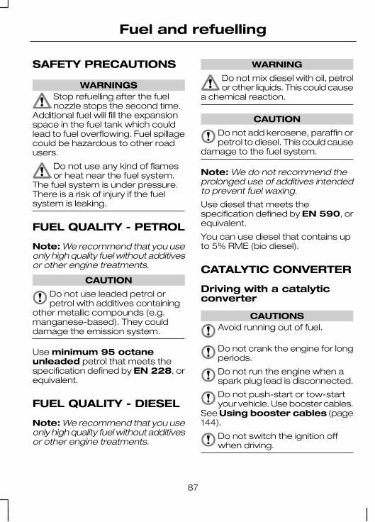
SAFETY PRECAUTIONS
WARNINGSStop refuelling after the fuelnozzle stops the second time.
Additional fuel will fill the expansionspace in the fuel tank which couldlead to fuel overflowing. Fuel spillagecould be hazardous to other roadusers.
Do not use any kind of flamesor heat near the fuel system.
The fuel system is under pressure.There is a risk of injury if the fuelsystem is leaking.
FUEL QUALITY - PETROL
Note: We recommend that you useonly high quality fuel without additivesor other engine treatments.
CAUTION
Do not use leaded petrol orpetrol with additives containing
other metallic compounds (e.g.manganese-based). They coulddamage the emission system.
Use minimum 95 octaneunleaded petrol that meets thespecification defined by EN 228, orequivalent.
FUEL QUALITY - DIESEL
Note: We recommend that you useonly high quality fuel without additivesor other engine treatments.
WARNING
Do not mix diesel with oil, petrolor other liquids. This could cause
a chemical reaction.
CAUTION
Do not add kerosene, paraffin orpetrol to diesel. This could cause
damage to the fuel system.
Note: We do not recommend theprolonged use of additives intendedto prevent fuel waxing.
Use diesel that meets thespecification defined by EN 590, orequivalent.
You can use diesel that contains upto 5% RME (bio diesel).
CATALYTIC CONVERTER
Driving with a catalyticconverter
CAUTIONSAvoid running out of fuel.
Do not crank the engine for longperiods.
Do not run the engine when aspark plug lead is disconnected.
Do not push-start or tow-startyour vehicle. Use booster cables.
See Using booster cables (page144).
Do not switch the ignition offwhen driving.
87
Fuel and refuelling

Parking
WARNING
Do not park your vehicle overdry leaves or dry grass. The
exhaust will continue to radiate aconsiderable amount of heat afteryou have switched the engine off.This is a potential fire hazard.
FUEL FILLER FLAP
WARNINGSTake care when refuelling toavoid spilling any residual fuel
from the fuel pipe nozzle.
We recommend that you waitat least 10 seconds before
removing the fuel pipe nozzle to allowany residual fuel to drain into the fueltank.
CAUTION
If you use a high pressure sprayto wash your vehicle, only spray
the fuel filler flap briefly from adistance not less than 20 centimetres(8 inches).
Note: It is normal to hear a hissingnoise when you remove the filler cap.
1
E66588
2
E95392
REFUELLING
CAUTION
Do not attempt to start theengine if you have filled the fuel
tank with the incorrect fuel. This coulddamage the engine. Have the systemchecked by a properly trainedtechnician immediately.
88
Fuel and refuelling

FUEL CONSUMPTION
The CO2 and fuel consumptionfigures are derived from laboratorytests according to EEC Directive80/1268/EEC and subsequentamendments and are carried out byall vehicle manufacturers.
They are intended as a comparisonbetween makes and models ofvehicles. They are not intended torepresent the real world fuelconsumption you may get from yourvehicle. Real world fuel consumptionis governed by many factorsincluding; driving style, high speeddriving, stop/start driving, airconditioning usage, the accessoriesfitted and towing etc.
Your Ford dealer can give you adviceon improving your fuel consumption.
TECHNICAL SPECIFICATIONS
Fuel consumption figures
CO2 emis-sionsCombinedExtra-
urbanUrban
Variant
g/kml/100 km(mpg)
l/100 km(mpg)
l/100 km(mpg)
2017.6 (37.2)6.6 (42.8)9.3 (30.4)Tourneo 2.2L DuraTorq-TDCi 62.5kW (85 PS),Axle ratio: 4.23
2017.6 (37.2)6.6 (42.8)9.3 (30.4)Tourneo 2.2L DuraTorq-TDCi 81kW (110 PS), Axleratio: 4.23
2077.8 (36.0)6.7 (42.2)9.8 (28.8)Tourneo 2.2L DuraTorq-TDCi 96kW (130 PS),Axle ratio: 4.54
195 - 1987.4 (38.2) -7.5 (37.7)
6.4 (44.1) -6.5 (43.5)
9.1 (31.0) -9.2 (30.7)
Kombi 2.2L DuraTorq-TDCi 62.5kW (85 PS),Axle ratio: 4.23
195 - 1987.4 (38.2) -7.5 (37.7)
6.4 (44.1) -6.5 (43.5)
9.1 (31.0) -9.2 (30.7)
Kombi 2.2L DuraTorq-TDCi 81kW (110 PS), Axleratio: 4.23
89
Fuel and refuelling

CO2 emis-sionsCombinedExtra-
urbanUrban
Variant
g/kml/100 km(mpg)
l/100 km(mpg)
l/100 km(mpg)
200 - 2037.6 (37.2) -7.7 (36.8)
6.7 (42.2) -6.8 (41.5)
9.1 (31.0) -9.2 (30.7)
Kombi 2.2L DuraTorq-TDCi 81kW (110 PS), Axleratio: 4.54
202 - 2047.6 (37.0) -7.7 (36.5)
6.5 (43.5) -6.6 (42.8)
9.6 (29.4) -9.7 (29.1)
Kombi 2.2L DuraTorq-TDCi 96kW (130 PS),Axle ratio: 4.54 up toT300
203 - 2067.7 (36.7) -7.8 (36.2)
6.7 (42.2) -6.8 (41.5)
9.4 (30.1) -9.5 (29.7)
Kombi 2.2L DuraTorq-TDCi 96kW (130 PS),Axle ratio: 4.54 T330and above
230 - 2388.7 (32.5) -9.0 (31.3)
7.3 (38.7) -7.7 (36.7)
11.1 (25.5) -11.3 (25.0)
Kombi 2.4L DuraTorq-TDCi 74kW (100 PS),Axle ratio: 4.78
245 - 2559.3 (30.5) -9.7 (29.2)
7.8 (36.2) -8.2 (34.5)
11.8 (23.9)- 12.2(23.2)
Kombi 2.4L DuraTorq-TDCi 74kW (100 PS),Axle ratio: 5.11
220 - 2258.3 (34.0) -8.5 (33.2)
7.1 (39.8) -7.3 (38.7)
10.4 (27.2)- 10.6(26.7)
Kombi 2.4L DuraTorq-TDCi 85kW (115 PS),Axle ratio: 3.73, 6-speedmanual transmission
247 - 2549.4 (30.2) -9.6 (29.3)
7.7 (36.7) -7.9 (35.8)
12.2 (23.2)- 12.6(22.4)
Kombi 2.4L DuraTorq-TDCi 85kW (115 PS),Axle ratio: 4.27, 6-speedmanual transmission
229 - 2388.7 (32.6) -9.0 (31.4)
7.2 (39.2) -7.6 (37.2)
11.2 (25.2)- 11.4 (24.8)
Kombi 2.4L DuraTorq-TDCi 103kW (140 PS),Axle ratio: 3.73, 6-speedmanual transmission
90
Fuel and refuelling

CO2 emis-sionsCombinedExtra-
urbanUrban
Variant
g/kml/100 km(mpg)
l/100 km(mpg)
l/100 km(mpg)
249 - 2609.4 (30.0) -9.8 (28.7)
7.7 (36.7) -8.1 (34.9)
12.4 (22.8)- 12.8 (22.1)
Kombi 2.4L DuraTorq-TDCi 103kW (140 PS),Axle ratio: 4.27, 6-speedmanual transmission
209 - 3419.8 (28.7)7.9 (35.8)12.9 (21.9)Kombi 3.2L DuraTorq-TDCi, Axle ratio: 3.58
222 - 38010.6 (26.7)8.4 (33.6)14.4 (19.6)Kombi 3.2L DuraTorq-TDCi, Axle ratio: 4.10
91
Fuel and refuelling

MANUAL TRANSMISSION
CAUTION
Do not engage reverse gearwhen the vehicle is moving. This
could cause damage to thetransmission.
Note: Fully depress the clutch pedaland wait for three seconds beforeyou select reverse gear.
Selecting reverse gear
Vehicles with a 5-speedtransmission
E68298
Vehicles with a 6-speedtransmission
1
2
E68299
ALL-WHEEL DRIVE (AWD)
CAUTION
A vehicle fitted with AWD mustbe recovered with either ALL
wheels on the ground or ALL wheelsoff the ground. See Vehiclerecovery (page 127).
92
Transmission

The AWD system, fitted to certainrear-wheel drive variants, is purelymechanical and will automaticallyprovide driving torque to the frontwheels when road conditionsbecome slippery with rain, snow orice etc.
While driving, the AWD indicatorilluminates during activation of thesystem. If it does not illuminate orilluminates continuously while driving,this indicates a malfunction. During amalfunction, the system switches off.Have the system checked by aproperly trained technician.
When AWD is no longer required thesystem automatically disengages andnormal rear-wheel drive functionalityis resumed.
93
Transmission
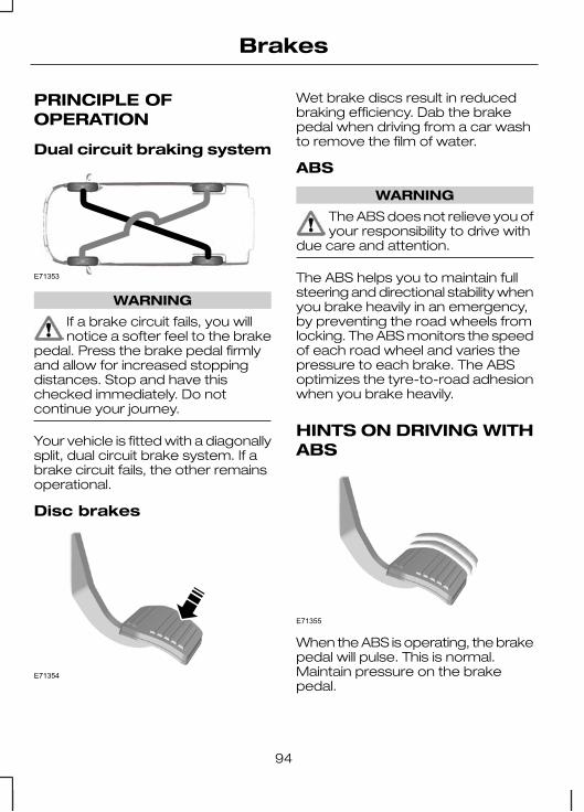
PRINCIPLE OFOPERATION
Dual circuit braking system
E71353
WARNING
If a brake circuit fails, you willnotice a softer feel to the brake
pedal. Press the brake pedal firmlyand allow for increased stoppingdistances. Stop and have thischecked immediately. Do notcontinue your journey.
Your vehicle is fitted with a diagonallysplit, dual circuit brake system. If abrake circuit fails, the other remainsoperational.
Disc brakes
E71354
Wet brake discs result in reducedbraking efficiency. Dab the brakepedal when driving from a car washto remove the film of water.
ABS
WARNING
The ABS does not relieve you ofyour responsibility to drive with
due care and attention.
The ABS helps you to maintain fullsteering and directional stability whenyou brake heavily in an emergency,by preventing the road wheels fromlocking. The ABS monitors the speedof each road wheel and varies thepressure to each brake. The ABSoptimizes the tyre-to-road adhesionwhen you brake heavily.
HINTS ON DRIVING WITHABS
E71355
When the ABS is operating, the brakepedal will pulse. This is normal.Maintain pressure on the brakepedal.
94
Brakes

The ABS will not eliminate thedangers inherent when:• you drive too close to the vehicle
in front of you.• the vehicle is aquaplaning.• you take corners too fast.• the road surface is poor.
PARKING BRAKE
Applying the parking brake
E66567
WARNING
Make sure that the parkingbrake is applied before you
release the lever.
Note: Do not press the releasebutton when you apply the parkingbrake.
1. Press the brake pedal firmly.2. Pull the parking brake lever
upwards to its fullest extent.
Parking on a hill
If you have to park facing uphill, selectfirst gear and turn the front wheelsaway from the kerb. If you have topark facing downhill, select reversegear and turn the front wheelstowards the kerb.
Releasing the parkingbrake
1. Press the brake pedal firmly.2. Pull the parking brake lever
upwards slightly, press the releasebutton and push the leverdownwards.
95
Brakes

PRINCIPLE OFOPERATION
Electronic stabilityprogramme (ESP)
WARNING
ESP does not relieve you of yourresponsibility to drive with due
care and attention.
E72903
A A
AB
B
B
B
without ESPA
with ESPB
The ESP supports stability when thevehicle starts to slide away from yourintended path. This is performed bybraking individual wheels andreducing engine torque as needed.
The system also provides anenhanced traction control functionby reducing engine torque if thewheels spin when you accelerate.This improves your ability to pull awayon slippery roads or loose surfaces,and improves comfort by limitingwheel spin in hairpin bends.
Stability control (ESP) warninglamp
The ESP warning lamp will flash whenthe system is operating. SeeWarning lamps and indicators(page 52).
Emergency brake assist
WARNING
Emergency brake assist doesnot relieve you of your
responsibility to drive with due careand attention.
Emergency brake assist will detectwhen you brake heavily by measuringthe rate at which you press the brakepedal. It will provide maximumbraking efficiency as long as youpress the pedal. Emergency brakeassist can reduce stopping distancesin critical situations.
96
Stability control

USING STABILITYCONTROL
E78085
With vehicle speed below 60 km/h(37 mph), press and hold the switchfor one second. The switch willilluminate.
Note: If you turn the system off, thesystem will reactivate temporarily ifthe brakes are applied during avehicle slide. The ESP warning lampwill flash in this instance.
Note: If you turn the system off, thesystem will automatically reactivateif your vehicle speed goes above 60km/h (37 mph).
Press the switch again to turn thesystem on. The system will beswitched on automatically every timeyou switch the ignition on.
For item location: See Quick start(page 6).
97
Stability control

PRINCIPLE OFOPERATION
The hill launch assist (HLA) systemmakes it easier to pull away when thevehicle is on a slope without the needto use the parking brake.
When the HLA is active, the vehiclewill remain stationary on the slope fortwo to three seconds after yourelease the brake pedal. During thistime, you have time to move yourfoot from the brake to theaccelerator pedal and pull away. Thebrakes are released automaticallyonce the engine has developedsufficient drive to prevent the vehiclefrom rolling down the slope. This isan advantage when pulling away ona slope, for example from a car parkramp, traffic lights or when reversinguphill into a parking space.
WARNING
The HLA does not replace theparking brake. When you leave
the vehicle, always apply the parkingbrake and select first or reverse gear.
USING HLA
The HLA is activated automaticallywhen the vehicle is stopped on aslope greater than 4%. HLA operateswith the vehicle facing downhill ifreverse gear is selected.
Activating the HLA
WARNINGSYou must remain in the vehicleonce you have activated the
HLA.
The HLA is active only if thegreen HLA lamp illuminates in
the instrument cluster. During alltimes you are responsible forcontrolling the vehicle, supervisingthe HLA and intervening, if required.
You can activate the HLA only if thefollowing conditions have been met:
• The engine is running.• All doors (including cargo doors)
are fully closed.• The parking brake is fully
disengaged.• No failure mode is present.
To activate the HLA:
1. Press the brake and clutch pedalsto bring the vehicle to a completestandstill. Keep the brake andclutch pedals depressed.
2. If the sensors detect that thevehicle is on a slope the HLA willbe activated automatically and thegreen HLA lamp will illuminate inthe instrument cluster.
3. When you remove your foot fromthe brake pedal, the vehicle willremain on the slope without rollingaway for approximately two tothree seconds. This hold time willautomatically be extended if youare in the process of driving off.
98
Hill launch assist (HLA)

4. Drive off in the normal manner.The brakes will be releasedautomatically.
WARNING
If the engine is revvedexcessively, or if a malfunction
is detected when the HLA is active,the HLA will be deactivated and thegreen HLA lamp will go out.
Deactivating the HLA
To deactivate the HLA, perform oneof the following:
• Apply the parking brake.• Open any door (including cargo
doors).• Drive off uphill without re-applying
the brake.• Wait for two to three seconds until
the HLA deactivates automatically.• If the HLA is active in a forward
gear, select reverse gear.• If the HLA is active in neutral,
release the clutch pedal.• If the HLA is active in reverse gear,
select neutral.
The green HLA lamp will go out.
Disabling the HLA
Your dealer can permanently disablethe HLA if required.
99
Hill launch assist (HLA)

PRINCIPLE OFOPERATION
The traction control system improvestraction when one wheel starts tospin at vehicle speeds up to 40 km/h(25 mph). If a wheel starts to spin, thetraction control system varies thepressure to the brake of that wheeluntil is stops spinning.
USING TRACTIONCONTROL
The traction control system isoperational when you switch theignition on.
The traction control indicator will flashwhen the system is operating. Slowlyaccelerate until the spinning wheelregains its traction.
The traction control system will stopworking temporarily if usedexcessively within a short period oftime. This is normal and has no effecton the brake system.
The traction control system willcontinue to operate when ESP isswitched off. The warning lamp in theinstrument cluster will not flash in thiscase.
100
Traction control

PRINCIPLE OFOPERATION
WARNING
The parking aid does not relieveyou of your responsibility to
drive with due care and attention.
CAUTIONSThe sensors may not detectobjects in heavy rain or other
conditions that cause disruptivereflections.
The sensors may not detectobjects with surfaces that absorb
ultrasonic waves.
The sensors may not detectobjects that are close to the
vehicle (approximately 30centimetres [11 inches] to the rearand above or below the sensors).
If you use a high pressure sprayto wash your vehicle, only spray
the sensors briefly from a distancenot less than 20 centimetres (8inches).
Note: The parking aid may emit falsetones if it detects a signal using thesame frequency as the sensors or ifthe vehicle is fully laden.
Note: The outer sensors may detectthe side walls of a garage. If thedistance between the outer sensorand the side wall remains constantfor three seconds, the tone willswitch off. As you continue, the innersensors will detect rearward objects.
USING THE PARKING AID
E71358
CAUTION
The parking aid may detect anaftermarket tow bar. The parking
aid will only indicate the distancebetween the bumper and theobstacle, not the distance betweenthe tow bar and the obstacle.
Note: Keep the sensors free fromdirt, ice and snow. Do not clean withsharp objects.
The parking aid is automaticallyactivated when you select reversegear with the ignition switched on.
101
Parking aid

You will hear an intermittent tone ata distance of up to 180 centimetresbetween the obstacle and rearbumper. Decreasing the distanceaccelerates the intermittent tone. Acontinuous tone will start at adistance of less than 40 centimetres.
Note: If a high pitch tone is heard forthree seconds, this indicates amalfunction. The system will switchoff automatically if it malfunctions.Have this checked as soon aspossible.
102
Parking aid

PRINCIPLE OFOPERATION
WARNING
The rear view camera does notrelieve you of your responsibility
to drive with due care and attention.
CAUTIONSIf you use a high pressure sprayto wash your vehicle, only spray
the rear view camera briefly from adistance not less than 20 centimetres(8 inches).
CAUTIONSDo not apply pressure to the rearview camera. The position and
the angle of the camera automaticallychanges.
Note: Keep the rear view camerafree from dirt, ice and snow. Do notclean with sharp objects, degreaser,wax or organic products. Use only asoft cloth.
A B C
E95058
103
Rear view camera

Rear view camera displayA
Rear view camera - liftgateB
Rear view camera - cargo doorC
The rear view camera is a visual aidfor use when reversing.
During operation, guide lines appearin the display which represent yourvehicle's path and approximatedistance from rearward objects.
USING THE REAR VIEWCAMERA
WARNINGSThe operation of the rear viewcamera may vary depending on
the ambient temperature, vehicle androad conditions.
The distances shown in thedisplay may differ from the
actual distance.
Do not place objects in front ofthe rear view camera.
Note: When you disengage reversegear, the display will stay on for a fewmore seconds before switching offautomatically.
Activating the rear viewcamera
E95060
CAUTION
The rear view camera may notdetect objects that are close to
the vehicle.
Engage the reverse gear to activatethe camera.
Note: The system will not functionunless the ignition is switched on.
The rear view camera may notoperate correctly in the followingconditions:• Dark areas.• Intense light.• If the ambient temperature
increases or decreases rapidly.• If the camera is wet, for example
in rain or high humidity.• If the camera's view is obstructed,
for example by mud.
104
Rear view camera

Using the display
CAUTIONSObstacles above the cameraposition will not be shown.
Inspect the area behind your vehicleif necessary.
Distance marks and width marksare for general guidance only,
and are calculated for vehicles inmaximum load conditions on an evenroad surface with the front wheels ina straight forward position.
Switching the rear viewcamera on and off
A
E95059
On and off buttonA
Press button A to manually switchthe system on and off.
Note: The button will only functionwhilst the reverse gear is selected.
105
Rear view camera

PRINCIPLE OFOPERATION
Cruise control allows you to controlyour speed using the switches on thesteering wheel. You can use cruisecontrol when you exceed 30 km/h(20 mph).
USING CRUISE CONTROL
WARNING
Do not use cruise control inheavy traffic, on twisty roads or
when the road surface is slippery.
Switching cruise control on
E75456
Note: The system is ready for youto set a speed.
Setting a speed
E75452
Press to store and maintain yourcurrent speed. The cruise controlindicator will illuminate. SeeWarning lamps and indicators(page 52).
Changing the set speed
WARNING
When you are going downhill,your speed may increase above
the set speed. The system will notapply the brakes. Change down agear and press the SET- switch toassist the system in maintaining theset speed.
Note: If you accelerate by pressingthe accelerator pedal, the set speedwill not change. When you releasethe accelerator pedal, you will returnto the speed that you previously set.
106
Cruise control

E95393
A
B
AccelerateA
DecelerateB
Cancelling the set speed
E75453
Press the brake pedal or the RESswitch.
Note: The system will no longercontrol your speed. The cruisecontrol indicator will not illuminate butthe system will retain the speed thatyou previously set.
Resuming the set speed
E75453
The cruise control indicator willilluminate and the system will attemptto resume the speed that youpreviously set.
Switching cruise control off
E75455
The system will not retain the speedthat you previously set. The cruisecontrol indicator will not illuminate.
107
Cruise control

GENERAL INFORMATION
WARNINGSUse load securing straps to anapproved standard, e.g. DIN.
Make sure that you secure allloose items properly.
Place luggage and other loadsas low and as far forward as
possible within the luggage orloadspace.
Do not drive with the tailgate orrear door open. Exhaust fumes
may enter the vehicle.
WARNINGSDo not exceed the maximumfront and rear axle loads for your
vehicle. See Vehicleidentification (page 171).
LOAD RETAININGFIXTURES
Note: The number of load retainingfixtures may vary depending on yourvehicle model.
Securing cargo
Note: The floor anchor pointscomply to DIN 75410 standard.
108
Load carrying

E75510
109
Load carrying

Supplementary retainingfixtures
Mid-height cargo rail
E77500
ROOF RACKS AND LOADCARRIERS
Roof rack
E71359
WARNINGSIf you use a roof rack, the fuelconsumption of your vehicle will
be higher and you may experiencedifferent driving characteristics.
Read and follow themanufacturer’s instructions
when you are fitting a roof rack.
CAUTIONSDo not exceed the maximumaxle load for your vehicle. See
Vehicle identification (page 171).
Do not exceed the maximumpermissible roof load of 150
kilogrammes (including the roof rack).
Check the security of the roof rackand its fittings as follows:• before starting• after driving 50 kilometres (30
miles)• at 1 000 kilometres (600 miles)
intervals.
Vehicles with anemergency exit
See Emergency exit (page 113).
110
Load carrying

TOWING A TRAILER
WARNINGSDo not exceed the maximumvehicle and trailer weight stated
on the vehicle identification plate. SeeVehicle identification (page 171).
Do not exceed a speed of 90km/h (55 mph) when towing
with a laden weight greater than 2000kg.
Note: Not all vehicles are suitable orapproved to have tow bars fitted.Check with your dealer first.
Place loads as low and central to theaxle(s) of the trailer as possible. If youare towing with an unladen vehicle,the load in the trailer should beplaced toward the nose, within themaximum nose load, as this gives thebest stability.
Note: The maximum trailer noseweight can be found on themanufacturers data plate on the towbar.
The stability of the vehicle to trailercombination is very much dependanton the quality of the trailer.
The maximum vehicle and trailerweights represent technically bindingvalues for gradients up to 12 % andat an altitude of 1 000 metres abovesea level. In high altitude regions,thinner atmosphere can reduceengine performance so the followingrestrictions will apply:
In high altitude regions, the stipulatedmaximum permitted gross trainweight must be reduced by 10% forevery 1 000 metres.
Steep gradients
WARNING
The overrun brake on a trailer isnot controlled by the anti-lock
braking system.
Change down a gear before youreach a steep downhill gradient.
111
Towing

RUNNING-IN
Tyres
WARNING
New tyres need to be run-in forapproximately 500 kilometres
(300 miles). During this time, you mayexperience different drivingcharacteristics.
Brakes and clutch
WARNING
Avoid heavy use of the brakesand clutch if possible for the first
150 kilometres (100 miles) in townand for the first 1 500 kilometres (1000 miles) on motorways.
Engine
CAUTION
Avoid driving too fast during thefirst 1 500 kilometres (1 000
miles). Vary your speed frequentlyand change up through the gearsearly. Do not labour the engine.
REDUCED ENGINEPERFORMANCE
Your vehicle can be driven briefly ifthe engine overheats, withoutdamage to the engine. The enginewill continue to operate with limitedpower. The distance you can traveldepends on ambient temperature,vehicle load, and terrain.
If the needle moves to the upper limitposition, the engine is overheating.See Gauges (page 49).
If the temperature continues to rise,the fuel supply to the engine will bereduced. The air conditioning (if fitted)will also be turned off and the enginecooling fan will operate.
CAUTION
Continued operation will increasethe engine temperature, and
cause the engine to shut downcompletely.
• Stop your vehicle as soon aspossible.
• Immediately turn off the engine toprevent severe engine damage.
• Wait for the engine to cool down.• Check the coolant level. See
Engine coolant check (page137).
• Have the vehicle checked by anexpert immediately.
112
Driving hints

FIRST AID KIT
Bus
Space for a first aid kit is locatedunderneath the second row seat.
Van, Kombi, Chassis cab,Flatbed truck
Space for a first aid kit is located inthe driver’s side door bin.
WARNING TRIANGLE
You will find a space for storing awarning triangle in driver side doorbin.
EMERGENCY EXIT
WARNING
Make sure that the roof rackand its load do not obstruct the
emergency exit. Ask your dealer foradvice on roof racks suitable for yourvehicle.
Break the glass with the hammer inan emergency.
113
Emergency equipment

FUEL CUT-OFF SWITCH
E71360
If you have an accident or a minorcollision (e.g. collision when parking),the fuel cut-off switch may stop thefuel supply. The switch is located onthe side panel in front of thepassenger side front door.
Resetting the fuel cut-offswitch
WARNING
Do not reset the fuel cut-offswitch if you see or smell fuel.
• Switch the ignition off.• Check the fuel system for leaks.• Press the top of the cut-off switch
to reset.• Switch the ignition on and, after a
few seconds, turn the key toposition I.
• Check the fuel system again forleaks.
INSPECTING SAFETYSYSTEM COMPONENTS
Seat belts
Belts subjected to strain, as a resultof an accident, should be renewedand the anchorages checked by aproperly trained technician.
114
Status after a collision

FUSE BOX LOCATIONS
Right-hand drive
A
BC
D
E70864
Left-hand drive
B
D AE91162
C
Pre-fuse boxA
Standard relay boxB
Passenger compartmentjunction box
C
Engine compartmentjunction box
D
Pre-fuse box
Driver seat
1
2
E70866
Standard relay box
E70869
22
1
115
Fuses

E70868
3
3
4
Passenger junction box
E70869
22
1
E70870
3
34
Note: When refitting, make sure youhear a click when engaging bothclips.
Engine junction box
E70867
For item location: SeeMaintenance (page 129).
116
Fuses

CHANGING A FUSE
WARNINGSDo not modify the electricalsystem of your vehicle in any
way. Have repairs to the electricalsystem and the replacement ofrelays and high current fuses carriedout by properly trained technicians.
Switch the ignition and allelectrical equipment off before
touching or attempting to change afuse.
CAUTION
Fit a replacement fuse with thesame rating as the one you have
removed.
Note: You can identify a blown fuseby a break in the filament.
Note: All fuses, except high currentfuses, are a push fit.
FUSE SPECIFICATION CHART
Pre-fuse box
E70871
117
Fuses

Circuits protectedColourAmpereratingFuse
Starter motor and alternatorgrey3501
Passenger junction box power supply -start relevantyellow602
Engine junction box power supply - non-start relevantblue1003
Heated front screen right-hand sidegreen404
Standard relay box power supply - non-start relevantblue1005
Heated front screen left-hand sidegreen406
Passenger junction box power supply -non-start relevantyellow607
Customer connection pointyellow608
Customer connection pointyellow609
Customer connection pointyellow6010
Circuits switchedRelay
Battery disconnect switchR1
118
Fuses

Engine junction box
E70872
CircuitsprotectedColourAmpere ratingFuse
Engine cooling fanyellow6011
Trailer tow andtrailer tow modulepower supply(KL30)
pink3012
ABS and ESPpump
green4013
Not used--14
Glow plugsyellow6015
Ignition relay(KL15 #3yellow6016
Starter enablepink3017
Ignition feed(KL15) toPassenger junc-tion box
green4018
119
Fuses

CircuitsprotectedColourAmpere ratingFuse
Not used--19
ABS, ESP,steering anglesensor, YAWsensor supply(KL30)
red1020
ABS and ESPvalves and controlunit
natural2521
PCM power relayyellow2022
Not used--23
Additional heater,programmablefuel-fired boosterheater
yellow2024 Diesel
Fuel pumpyellow2024 Petrol
Battery-fed relaycoilstan525
PCM Powerblue1526
Glow plug monit-oringbrown7.527
T-MAF sensortan528 Diesel
Catalyst monit-oring system andHEGO sensors
blue1528 Petrol
Water in fuelsensor (Dieselonly), powersupply relay coils
tan529
120
Fuses

CircuitsprotectedColourAmpere ratingFuse
Sonic purge valve,injector valves(Petrol only)
red1030
Vehicle speedsensortan531
Vaporiser glowplugyellow2032 Diesel
Coil on plug igni-tion moduleyellow2032 Petrol
Reversing lampsred1033
Trailer tow powersupply (KL15)yellow2034
Additional heater(KL15)tan535
Air conditioningclutchred1036
Ignition-fed relaycoils, PCM ignitionrun key sense
tan537
Circuits switchedRelay
Glow plugsR2
Not usedR3
Starter enableR4
Power feed (KL15 #4)R5
Power feed (KL15 #3)R6
Vaporiser glow plugR7 Diesel
Fuel pumpR7 Petrol
121
Fuses

Circuits switchedRelay
Powetrain control module powerR8
Not usedR9
Air conditioning clutch solenoidR10
Standard relay box
E70873
Circuits protectedColourAmpereratingFuse
Rear window wiperyellow2038
Front and rear air conditioning controlred1039
Relay coils supplytan540
122
Fuses

Circuits protectedColourAmpereratingFuse
Tachographtan541
Headlamp levelling, master light switch(KL15)tan542
Heated front seatsyellow2043
Hornyellow2044
Auxiliary powerpoint frontyellow2045
Heated door mirrors, if CAT 1 fittedred1046
Cigar lighteryellow2047
Relay coils supply, power mirrorstan548
Auxiliary powerpoint rearyellow2049
Main beam left-hand sidered1050
Main beam right-hand sidered1051
Dipped beam left-hand sidered1052
Dipped beam right-hand sidered1053
Pre-fuse for dipped beam, main beam,daytime running lamps, tachograph,fuel-fired booster heater blower
pink3054
Heater blower motorgreen4055
Power windowsyellow2056
Rear heater blower motorpink3057
Front wiper motorpink3058
Heated rear window, heated doormirrorspink3059
Not used--60
Ignition relay (KL15 #1)yellow6061
Ignition relay (KL15 #2)yellow6062
123
Fuses

Circuits switchedRelay
Headlamp dip beamR11
Heated door mirrors (if CAT 1 alarm is fitted)R12
Headlamp main beamR13
HornR14
Daytime running lampsR15
Programmable fuel fired heaterR16
Heated rear windows and heated door mirrors (orheated rear window left-hand side if Cat 1 alarm isfitted)
R17
Heated rear window right-hand side if Cat 1 alarmis fittedR18
Power feed (KL15 #2)R19
Reserved for special vehicle operation useR20
Power feed (KL15 #1)R21
Heated windscreen right-hand sideR22
Windscreen wiper high and low functionR23
Rear window wiperR24
Windscreen wiper on and off functionR25
Heated windscreen left-hand sideR26
124
Fuses

Passenger junction box
E70874
Circuits protectedColourAmpereratingFuse
Rear parking aid, rain sensortan563
Acceleration pedal demand sensorgrey264
Brake lamp switchblue1565
Instrument cluster, PATS supply,tachograph, instrument panel switchillumination
tan566
Wiper stalk switchred1067
Restraints control modulered1068
Exterior lamp switch (KL15)yellow2069
Battery backed sounderyellow2070
Exterior lamp switch (KL30)tan571
125
Fuses

Circuits protectedColourAmpereratingFuse
Battery saver supply, OBDII (KL30)red1072
Radio, navigation unit and phone supplyblue1573
Instrument cluster, fuel-fired boosterheater timer, remote keyless entrysupply, interior motion sensor (KL30)
tan574
Side lamps right-hand sidetan575
Side lamps left-hand sidebrown7.576
Ignition switch supply, battery discon-nect switch coils supplytan577
Central lockingblue1578
Number plate lamp, side markersbrown7.579
Front fog lampsblue1580
Rear fog lampsred1081
Radio, navigation unit, instrumentclustergrey282
Auxiliary fuses
LocationCircuitsprotectedColourAmpere
ratingFuse
Left-hand side foot-well
Trailer tow modulered1083
126
Fuses

TOWING POINTS
E71361
A
B
C
Front towing eyeA
Rear towing eye (Van, Busand Kombi)
B
Rear towing eye (ChassisCab and Flatbed truck)
C
TOWING THE VEHICLEON FOUR WHEELS
All vehicles
WARNINGSSwitch the ignition on when yourvehicle is being towed. The
steering lock will engage and thedirection indicators and brake lampswill not work if you do not.
The brake servo and the powersteering pump do not operate
unless the engine is running. Pressthe brake pedal harder and allow forincreased stopping distances andheavier steering.
CAUTIONSToo much tension in the towrope could cause damage to
your vehicle or the vehicle that istowing.
Do not use a rigid tow bar on thefront towing eye.
Drive off slowly and smoothly withoutjerking the vehicle that is towing.
Vehicles with automatictransmission
CAUTIONSDo not tow your vehicle fasterthan 50 km/h (30 mph) or further
than 50 kilometres (30 miles).
127
Vehicle recovery

CAUTIONSIf a speed of 50 km/h (30 mph)and a distance of 50 kilometres
(30 miles) is to be exceeded the drivewheels must be lifted clear of theground.
In the event of a mechanicalfailure of the transmission the
drive wheels must be lifted clear ofthe ground.
Do not tow your vehiclebackwards.
Select neutral when your vehicleis being towed.
TOWING THE VEHICLEON FOUR WHEELS - AWD
WARNINGSSwitch the ignition on when yourvehicle is being towed. The
steering lock will engage and thedirection indicators and brake lampswill not work if you do not.
The brake servo and the powersteering pump do not operate
unless the engine is running. Pressthe brake pedal harder and allow forincreased stopping distances andheavier steering.
CAUTIONSToo much tension in the towrope could cause damage to
your vehicle or the vehicle that istowing.
Do not use a rigid tow bar on thefront towing eye.
CAUTIONSIn the event of a breakdown or amechanical failure of the
transmission your vehicle must berecovered with either ALL wheels onthe ground or transported with ALLwheels off the ground.
Drive off slowly and smoothly withoutjerking the vehicle that is towing.
128
Vehicle recovery

GENERAL INFORMATION
Have your vehicle serviced regularlyto help maintain its roadworthinessand resale value. There is a largenetwork of Ford Authorised Repairersthat are there to help you with theirprofessional servicing expertise. Webelieve that their specially trainedtechnicians are best qualified toservice your vehicle properly andexpertly. They are supported by awide range of highly specialised toolsdeveloped specifically for servicingyour vehicle.
In addition to regular servicing, werecommend that you carry out thefollowing additional checks.
WARNINGSSwitch the ignition off beforetouching or attempting
adjustment of any kind.
Do not touch the electronicignition system parts after you
have switched the ignition on orwhen the engine is running. Thesystem operates at high voltage.
Keep your hands and clothingclear of the engine cooling fan.
Under certain conditions, the fan maycontinue to run for several minutesafter you have switched the engineoff.
Daily checks
• Exterior lamps.• Interior lamps.• Warning lamps and indicators.
Check when refuelling
• Engine oil level. See Engine oilcheck (page 136).
• Brake fluid level. See Brake andclutch fluid check (page 137).
• Washer fluid level. See Washerfluid check (page 139).
• Tyre pressures (when cold). SeeWheels and tyres (page 153).
• Tyre condition. See Wheels andtyres (page 153).
Monthly checks
• Engine coolant level (engine cold).See Engine coolant check(page 137).
• Pipes, hoses and reservoirs forleaks.
• Power steering fluid level. SeePower steering fluid check(page 138).
• Air conditioning operation.• Parking brake operation.• Horn operation.• Tightness of wheel nuts. See
Wheels and tyres (page 153).
129
Maintenance

OPENING AND CLOSINGTHE BONNET
Opening the bonnet
E72108
1 3
2
E72109
4
5
Closing the bonnet
Note: Make sure that the bonnet isclosed properly.
Lower the bonnet and allow it to dropfrom under its own weight for the last20–30 centimetres.
130
Maintenance
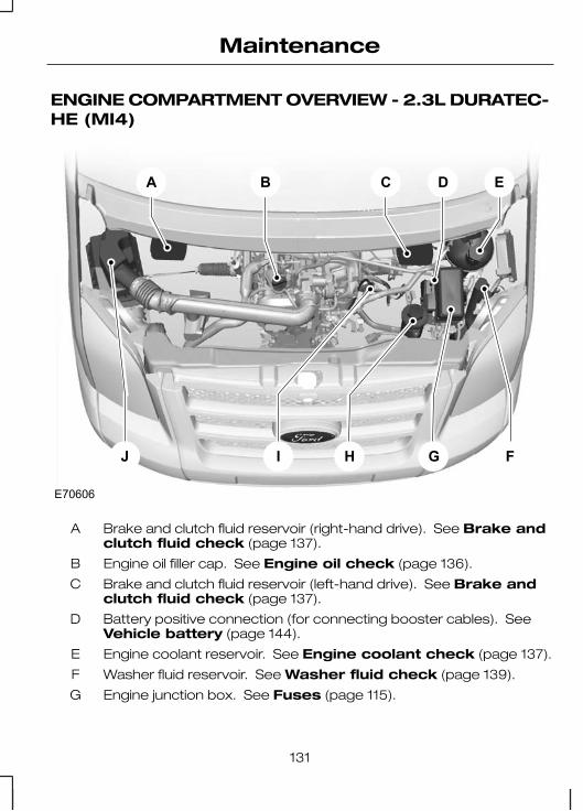
ENGINE COMPARTMENT OVERVIEW - 2.3L DURATEC-HE (MI4)
A B C D
GHIJ F
E
E70606
Brake and clutch fluid reservoir (right-hand drive). See Brake andclutch fluid check (page 137).
A
Engine oil filler cap. See Engine oil check (page 136).B
Brake and clutch fluid reservoir (left-hand drive). See Brake andclutch fluid check (page 137).
C
Battery positive connection (for connecting booster cables). SeeVehicle battery (page 144).
D
Engine coolant reservoir. See Engine coolant check (page 137).E
Washer fluid reservoir. See Washer fluid check (page 139).F
Engine junction box. See Fuses (page 115).G
131
Maintenance

Power steering fluid reservoir. See Power steering fluid check(page 138).
H
Engine oil dipstick. See Engine oil check (page 136).I1 The filler caps and the engine oil dipstick are coloured for easy identification.
ENGINE COMPARTMENT OVERVIEW - 2.2LDURATORQ-TDCI (PUMA) DIESEL
A B C D
GHIJ F
E
E70605
132
Maintenance
Fuel filter water trap (left-hand drive). See Draining the fuel filterwater trap (page 138).
A
Brake and clutch fluid reservoir (right-hand drive). See Brake andclutch fluid check (page 137).
A
Engine oil filler cap. See Engine oil check (page 136).B
Air cleaner.C
Brake and clutch fluid reservoir (left-hand drive). See Brake andclutch fluid check (page 137).
D
Fuel filter water trap (right-hand drive). See Draining the fuel filterwater trap (page 138).
D
Engine coolant reservoir. See Engine coolant check (page 137).E
Washer fluid reservoir. See Washer fluid check (page 139).F
Engine junction box. See Fuses (page 115).G
Battery positive connection (for connecting booster cables). SeeVehicle battery (page 144).
H
Engine oil dipstick. See Engine oil check (page 136).I
Power steering fluid reservoir. See Power steering fluid check(page 138).
J
1 The filler caps and the engine oil dipstick are coloured for easy identification.
133
Maintenance

ENGINE COMPARTMENT OVERVIEW - 2.4LDURATORQ-TDCI (PUMA) DIESEL/3.2L DURATORQ-TDCI (PUMA) DIESEL
A B C D
GHIJ F
E
E70607
Fuel filter water trap (left-hand drive). See Draining the fuel filterwater trap (page 138).
A
Brake and clutch fluid reservoir (right-hand drive). See Brake andclutch fluid check (page 137).
A
Engine oil dipstick1. See Engine oil check (page 136).B
Engine oil filler cap1. See Engine oil check (page 136).C
Brake and clutch fluid reservoir (left-hand drive). See Brake andclutch fluid check (page 137).
D
134
Maintenance

Fuel filter water trap (right-hand drive). See Draining the fuel filterwater trap (page 138).
D
Engine coolant reservoir. See Engine coolant check (page 137).E
Washer fluid reservoir. See Washer fluid check (page 139).F
Engine junction box. See Changing a fuse (page 117).G
Battery positive connection (for connecting booster cables). SeeUsing booster cables (page 144).
H
Air cleaner. Power steering fluid reservoir. See Power steeringfluid check (page 138).
I
Air cleaner.J1 The filler caps and the engine oil dipstick are coloured for easy identification.
ENGINE OIL DIPSTICK -2.3L DURATEC-HE (MI4)
E92036
A B
MINA
MAXB
ENGINE OIL DIPSTICK -2.2L DURATORQ-TDCI(PUMA) DIESEL
E90983
A B
MINA
MAXB
135
Maintenance

ENGINE OIL DIPSTICK -2.4L DURATORQ-TDCI(PUMA) DIESEL/3.2LDURATORQ-TDCI (PUMA)DIESEL
E71362
A B
MINA
MAXB
ENGINE OIL CHECK
CAUTION
Do not use oil additives or otherengine treatments. Under certain
conditions, they could damage theengine.
Note: The oil consumption of newengines reaches its normal level afterapproximately 5 000 kilometres (3000 miles).
Checking the oil level
CAUTION
Make sure that the level isbetween the MIN and the MAX
marks.
Note: Check the level before startingthe engine.
Note: Make sure that your vehicleis on level ground.
Note: Oil expands when it is hot. Thelevel may therefore extend a fewmillimetres beyond the MAX mark.
Remove the dipstick and wipe it witha clean, lint free cloth. Replace thedipstick and remove it again to checkthe oil level.
If the level is at the MIN mark, top upimmediately.
Topping up
WARNINGSOnly top up when the engine iscold. If the engine is hot, wait 10
minutes for the engine to cool down.
Do not remove the filler capwhen the engine is running.
Remove the filler cap.
CAUTION
Do not top up further than theMAX mark.
Top up with fluid that meets the Fordspecification. See Technicalspecifications (page 139).
136
Maintenance

ENGINE COOLANTCHECK
Checking the coolant level
WARNING
Do not allow the fluid to touchyour skin or eyes. If this
happens, rinse the affected areasimmediately with plenty of water andcontact your doctor.
CAUTION
Make sure that the level isbetween the MIN and the MAX
marks.
Note: Coolant expands when it ishot. The level may therefore extendbeyond the MAX mark.
If the level is at the MIN mark, top upimmediately.
Topping up
WARNINGSOnly top up when the engine iscold. If the engine is hot, wait 10
minutes for the engine to cool down.
Do not remove the filler capwhen the engine is running.
Do not remove the filler capwhen the engine is hot. Wait for
the engine to cool down.
Unscrew the cap slowly. Anypressure will escape slowly as youunscrew the cap.
CAUTIONSDo not spill coolant on any partof the engine.
Do not top up further than theMAX mark.
Top up with fluid that meets the Fordspecification. See Technicalspecifications (page 139).
BRAKE AND CLUTCHFLUID CHECK
WARNING
Do not allow the fluid to touchyour skin or eyes. If this
happens, rinse the affected areasimmediately with plenty of water andcontact your doctor.
CAUTION
Make sure that the level isbetween the MIN and the MAX
marks.
Note: The brake and the clutchsystems are supplied from the samereservoir.
If the level is at the MIN mark, top upimmediately.
Topping up
Remove the filler cap.
137
Maintenance

CAUTION
Do not top up further than theMAX mark.
Top up with fluid that meets the Fordspecification. See Technicalspecifications (page 139).
POWER STEERING FLUIDCHECK
WARNING
Do not allow the fluid to touchyour skin or eyes. If this
happens, rinse the affected areasimmediately with plenty of water andcontact your doctor.
CAUTION
Make sure that the level isbetween the MIN and the MAX
marks.
If the level is at the MIN mark, top upimmediately.
Topping up
Remove the filler cap.
CAUTION
Do not top up further than theMAX mark.
Top up with fluid that meets the Fordspecification. See Technicalspecifications (page 139).
DRAINING THE FUELFILTER WATER TRAP
Vehicles with a dieselengine
WARNING
Do not dispose of diesel inhousehold refuse or the public
sewage system. Use your localauthorised waste disposal facilities.
Note: With the engine running, thewater-in-fuel indicator lamp will goout after approximately 2 seconds.
Note: Only add fuel that meets theFord specification. See Fuel andrefuelling (page 87).
E77043
12
3
138
Maintenance

1. Disconnect the electricalconnector.
2. Attach a suitable hose to thesensor drain and direct the hoseinto a suitable container.
3. Unscrew the sensor one to twoturns and allow the water to drain.
Install in the reverse order.
WASHER FLUID CHECK
Note: The front and rear washersystems are supplied from the samereservoir.
TECHNICAL SPECIFICATIONS
Vehicle fluids
SpecificationRecommended fluidPart
WSS-M2C913-BFord or MotorcraftFormula E SAE 5W-30
Engine Oil2
Engine oil
WSA-M2C195-AFord Power SteeringFluid
Power assisted steering
WSS-M97B44-DMotorcraft SuperPlusAntifreeze
Coolant
ESD-M6C57-AFord or Motorcraft SuperDOT 4 Brake Fluid
Brake fluid
WSS-M2C939AFord Hypoid OilRear axle1
1Under normal operating conditions the rear axle requires no maintenance.However, in the event the rear axle becomes submerged under water, havethe fluid changed by your dealer.2 You can use an alternative SAE 5W-30engine oil, providing it meets the specification defined by WSS-M2C913-B.
Note: If you operate your vehicle in temperatures below -20°C, you mustnot use SAE 10W-40 engine oil.
Topping up the oil: If you are unable to find an oil that meets thespecification defined by WSS-M2C913-B, you must use SAE 5W-30(preferred), SAE 5W-40 or SAE 10W-40 that meets the specification definedby either ACEA A1/B1 (preferred) or ACEA A3/B3. Using these oils can resultin longer engine cranking periods, reduced engine performance, reducedfuel economy and increased emission levels.
139
Maintenance

Capacities
Capacity in litres(gallons)ItemVariant
MAX-markPower assisted steeringfluidAll
5.5 (1.2)Windscreen washersystemAll
80 (17.6)Fuel tankAll - Normal capacity
103 (22.7)Fuel tankIncreased capacity
4.3 (1.0)Engine oil − with filter2.3L Duratec-HE
3.9(0.9)Engine oil − without filter2.3L Duratec-HE
10.1 (2.2)Cooling system withauxiliary heater2.3L Duratec-HE
7.8 (1.7)Cooling system withfront heater only2.3L Duratec-HE
6.2 (1.4)Engine oil − with filter2.2L DuraTorq-TDCi
5.9 (1.3)Engine oil − without filter2.2L DuraTorq-TDCi
6.9 (1.5)Engine oil − with filter2.4L DuraTorq-TDCi
6.5 (1.4)Engine oil − without filter2.4L DuraTorq-TDCi
13 (2.9)Cooling system with fuelfired heater and auxiliaryheater
2.2L and 2.4L DuraTorq-TDCi
12.8 (2.9)Cooling system withauxiliary heater
2.2L and 2.4L DuraTorq-TDCi
11.5 (2.5)Cooling system with fuelfired heater
2.2L and 2.4L DuraTorq-TDCi
10 (2.2)Cooling system withfront heater only
2.2L and 2.4L DuraTorq-TDCi
12.6 (2.8)Engine oil − with filter3.2L DuraTorq-TDCi
140
Maintenance

Capacity in litres(gallons)ItemVariant
12 (2.6)Engine oil − without filter3.2L DuraTorq-TDCi
7.3 (1.6)Cooling system3.2L DuraTorq-TDCi
Engine oil top up capacities
litresEngine
1.52.2L DuraTorq-TDCi
0.72.3L Duratec-HE
22.4L DuraTorq-TDCi
Information not available3.2L DuraTorq-TDCi
141
Maintenance

CLEANING THEEXTERIOR
WARNING
If you use a car wash with awaxing cycle, make sure that
you remove the wax from thewindscreen.
CAUTIONSSome car wash installations usewater at high pressure. This
could damage certain parts of yourvehicle.
Remove the aerial before usingan automatic car wash.
Switch the heater blower off toprevent contamination of the
fresh air filter.
We recommend that you wash yourvehicle with a sponge and lukewarmwater containing a car shampoo.
Cleaning the headlamps
CAUTIONSDo not scrape the headlamplenses or use abrasives or
chemical solvents to clean them.
Do not wipe the headlampswhen they are dry.
Cleaning the rear window
CAUTION
Do not scrape the inside of therear window or use abrasives or
chemical solvents to clean it.
Use a clean, lint free cloth or a dampchamois leather to clean the insideof the rear window.
Cleaning the chrome trim
CAUTION
Do not use abrasives or chemicalsolvents. Use soapy water.
Body paintworkpreservation
CAUTIONSDo not polish your vehicle instrong sunshine.
Do not allow polish to touchplastic surfaces. It could be
difficult to remove.
Do not apply polish to thewindscreen or rear window. This
could cause the wipers to becomenoisy and they may not clear thewindow properly.
We recommend that you wax thepaintwork once or twice a year.
142
Vehicle care

CLEANING THE INTERIOR
Seat belts
WARNINGSDo not use abrasives, orchemical solvents to clean
them.
Do not allow moisture topenetrate the seat belt retractor
mechanism.
Clean the seat belts with interiorcleaner or water applied with a softsponge. Let the seat belts drynaturally, away from artificial heat.
REPAIRING MINOR PAINTDAMAGE
CAUTION
Remove apparently harmlesslooking substances from the
paintwork immediately (e.g. birddroppings, tree resins, insectremains, tar spots, road salt andindustrial fall out).
You should repair paintwork damagecaused by stones from the road orminor scratches as soon as possible.A choice of products is available fromyour Ford Dealer. Read and followthe manufacturer’s instructions.
143
Vehicle care

BATTERY CARE
The battery requires very littlemaintenance. The fluid level ischecked regularly during the routineservice inspections.
USING BOOSTERCABLES
CAUTIONSConnect batteries with only thesame nominal voltage.
Always use booster cables withinsulated clamps and adequate
size cable.
Do not disconnect the batteryfrom the vehicle’s electrical
system.
To connect the boostercables
E71367
A
B
DC
Flat battery vehicleA
Booster battery vehicleB
Positive connection cableC
Negative connection cableD
1. Position the vehicles so that theydo not touch one another.
2. Switch off the engine and anyelectrical equipment.
3. Lift up the battery plus connectioncover. See Maintenance (page129).
4. Connect the positive (+) terminalof the battery plus connection onvehicle A with the positive (+)terminal of vehicle B (cable C).
144
Vehicle battery

5. Connect the negative (-) terminalto the engine block or the enginemount of vehicle B. Connect theother end to the engine block orthe engine mount of vehicle A(cable D).
1
2
E71368
CAUTIONSDo not connect to the negative(–) terminal of the flat battery.
Make sure that the jump leadsare clear of any moving parts.
To start the engine
1. Run the engine of vehicle B atmoderately high speed.
2. Start the engine of vehicle A.
3. Run both vehicles for a minimumof three minutes beforedisconnecting the leads.
CAUTION
Do not switch on the headlampswhen disconnecting the cables.
The peak voltage could blow thebulbs.
Disconnect the cables in the reverseorder.
CHANGING THE VEHICLEBATTERY
CAUTION
Make sure the battery box iscorrectly sealed.
Note: The battery is located insidethe vehicle under the driver’s seat.
E66643
1. Remove the battery cover.
2. Turn the safety pin anti-clockwiseand take it out.
3. Slide the cover off the front of thebattery.
Install in the reverse order.
145
Vehicle battery

If the battery has been disconnectedthe vehicle may exhibit some unusualdriving characteristics forapproximately 8 km (5 miles) afterbattery reconnection while theengine management system realignsitself with the engine.
Where applicable, the audio systemmust be reprogrammed with thekeycode.
BATTERY CONNECTIONPOINTS
E75702
2
1
CAUTION
Do not connect any electricalitems directly to the vehicle
batteries.
There are three connection pointsavailable, each provides a maximumof 60A current. Ask your dealer foradvice on accessories suitable foryour vehicle.
1. Release the clips.2. Raise the cover.
146
Vehicle battery

CHILD SEATS
E68916
WARNINGSSecure children that are lessthan 150 centimetres tall or less
than 12 years of age in a suitable,approved child restraint, in the rearseat.
Original text according to ECER94.01: Extreme Hazard! Do not
use a rearward facing child restrainton a seat protected by an air bag infront of it!
Read and follow themanufacturer’s instructions
when you are fitting a child restraint.
Do not modify child restraints inany way.
Do not hold a child on your lapwhen the vehicle is moving.
Do not leave unattendedchildren in your vehicle.
WARNINGSIf your vehicle has been involvedin an accident, have the child
restraints checked by properlytrained technicians.
Note: Mandatory use of childrestraints varies from country tocountry.
A choice of ECE approved childrestraints which have beenspecifically tested and approved foryour vehicle are available from yourDealer.
Child restraints for differentmass groups
Use the correct child restraint asfollows:
Baby safety seat
E68918
Secure children that weigh less than13 kilogrammes in a rearward facingbaby safety seat in the rear seat.
147
Child safety

Child safety seat
E68920
Secure children that weigh between13 and 18 kilogrammes in a childsafety seat in the rear seat.
CHILD SEAT POSITIONING
Child seat positions
Mass group categories
Seating positions
3210+0
22 - 36kg
15 - 25kg
9 - 18 kgUp to 13kg
Up to 10kg
Boosterseat orcushion
Boosterseat orcushion
Childsafetyseat
Babysafetyseat
Babysafetyseat
XXXXXFront passengerseat with airbag
U1U1U1U1U1Front passengerseat without airbag
UUUUURear seats
XXIUIUIURear ISOFIX 2nd row
XXA, B, B1,C, DC, D, EEISOFIX size class*
X Not suitable for children in this mass group.
148
Child safety

U Suitable for universal category child restraints approved for use in this massgroup.
IU Suitable for universal category ISOFIX child restraints approved for use inthis mass group.
U1 Suitable for universal category child restraints approved for use in this massgroup.
* As defined by ECE 16.
149
Child safety

BOOSTER CUSHIONS
WARNINGSDo not install a booster seat ora booster cushion with only the
lap strap of the seat belt.
Do not install a booster seat ora booster cushion with a seat
belt that is slack or twisted.
Do not put the seat belt underyour child’s arm or behind its
back.
Do not use pillows, books ortowels to boost your child’s
height.
Make sure that your children sitin an upright position.
Secure children that weigh morethan 15 kilogrammes but are
less than 150 centimetres tall in abooster seat or a booster cushion.
Booster seat
E70710
We recommend that you use abooster seat that combines acushion with a backrest instead of abooster cushion only. The raisedseating position will allow you toposition the shoulder strap of theadult seat belt over the centre of yourchild’s shoulder and the lap straptightly across its hips.
Booster cushion
E68924
150
Child safety

ISOFIX ANCHOR POINTS
E68945
WARNING
Use an anti-rotation devicewhen using the ISOFIX system.
We recommend that you use a toptether or a support leg.
Note: When you are purchasing anISOFIX restraint, make sure that youknow the correct mass group andISOFIX size class for the intendedseating locations. See Child seatpositioning (page 148).
Your vehicle is fitted with ISOFIXanchor points that accommodateuniversally approved ISOFIX childrestraints.
The ISOFIX system comprises tworigid attachment arms on the childrestraint that attach to anchor pointson the 2nd row seats, where thecushion and backrest meet. Tetheranchor points are fitted to the rear ofthe 2nd row seats for child restraintswith a top tether.
Attaching a child restraintwith a top tether
E68946
WARNING
Do not attach a tether strap toanything other than the correct
tether anchor point.
151
Child safety

CHILD SAFETY LOCKS
E74584
A B
OnA
OffB
WARNING
You cannot open the doorsfrom the inside if you have put
the child safety locks on.
152
Child safety

GENERAL INFORMATION
Set the pressure for your spare tyreto the highest value given for yourvehicle and tyre size combination.
Data about tyres, rims and tyrepressures for special vehicle modelvariants is only given on the tyrepressure decal on these vehicles.
A decal with tyre pressure data islocated in the driver’s door openingat the B-pillar.
CHANGING A ROADWHEEL
Spare wheel
CAUTION
Use only approved wheel andtyre sizes. Using other sizes
could damage the vehicle and willmake the National Type Approvalinvalid.
The spare wheel is locatedunderneath the rear of the vehicle.
Single rear wheel vehicles
E70947
Double rear wheel vehicles
E70948
If your vehicle has a security bolt,remove it by turning anti-clockwise.
Fully insert the flat end of the wheelbrace (Bus, Van and Kombi) or theshort arm of the jack handle (Chassiscab and Flatbed truck) into the guidehole. Turn anti-clockwise until thewheel rests on the ground, and thereis slack in the cable.
153
Wheels and tyres

E70949
1 1
2
1. Remove the wing nut(s).2. Pass the bracket and cable
through the wheel opening.
Vehicle jack
CAUTION
Use only the specified jackingpoints. Positioning at other points
may damage the body, steering,suspension, engine, braking systemor fuel lines.
The jack, wheel brace and jackhandle are located in a storagecompartment in the front rightstepwell.
430 series vehicles
Hydraulic jack
E74102
All except 430 series vehicles
Scissor jack
E70950
Front jacking points
CAUTION
Make sure that when positioningthe jack, on a vehicle fitted with
rear air conditioning (A/C), that itdoes not come in contact with theA/C lines or the fuel tank supportstrap.
154
Wheels and tyres

430 series vehicles
E70951
Position the jack under theprotrusions at the rear of thesub-frame.
All except 430 series vehicles
E70952
Close the flap on the top of the jack(storage position). The frontsub-frame rear bolts fit into a recesson the flap of the jack.
155
Wheels and tyres

Rear jacking points
Front-wheel drive Bus, Vanand Kombi (260, 280 and 300series vehicles)
E70953
Open the flap on top of the jack.Position under the rear leaf springdirectly in front of the rear wheel.
Front-wheel drive Bus, Vanand Kombi (330 and 350series vehicles)
Note: An additional block is locatedinside the spare wheel.
E70954
Open the flap on top of the jack.Place the jack onto the block.
430 series vehicles
Note: Position the jack under theaxle, as near the wheel being jackedas possible.
156
Wheels and tyres
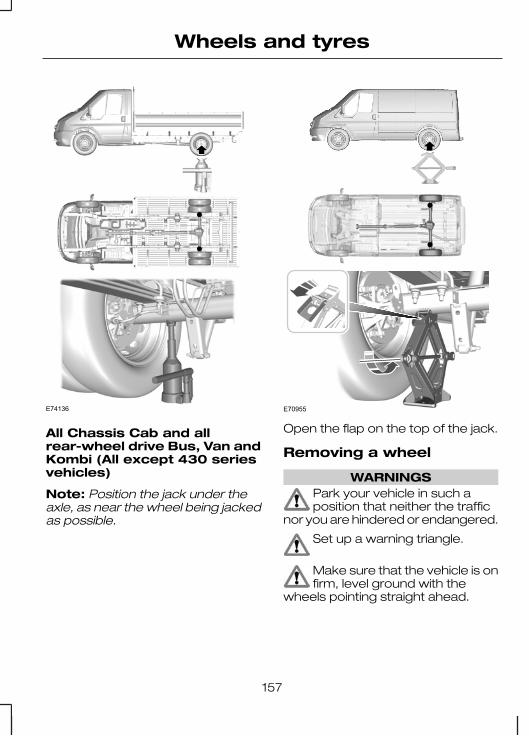
E74136
All Chassis Cab and allrear-wheel drive Bus, Van andKombi (All except 430 seriesvehicles)
Note: Position the jack under theaxle, as near the wheel being jackedas possible.
E70955
Open the flap on the top of the jack.
Removing a wheel
WARNINGSPark your vehicle in such aposition that neither the traffic
nor you are hindered or endangered.
Set up a warning triangle.
Make sure that the vehicle is onfirm, level ground with the
wheels pointing straight ahead.
157
Wheels and tyres

WARNINGSSwitch off the ignition and applythe handbrake. Select first or
reverse gear.
Have the passengers leave thevehicle.
Always secure the diagonallyopposite wheel with an
appropriate block or wheel chockwhen changing a wheel.
Make sure that the arrows ondirectional tyres point in the
direction of rotation when the vehicleis moving forwards. If a spare wheelhas to be fitted with the arrowspointing in the opposite direction ofrotation, have the tyre refitted in thecorrect direction by a properly trainedtechnician.
Only use the vehicle jack tochange a wheel. Never work
underneath the vehicle when it issupported only by the jack.
Note: Make sure that the jack isvertical to the jacking point and thebase is flat on the ground.
E70956
• Remove the hub cover.• Remove the nut caps.• Slacken the wheel nuts.
430 series vehicles
E70959
• Slide the flat end of the jackhandle over the locking valve.Turn the handle fully clockwise.Insert the handle into the pump,and lift the vehicle using apumping motion.
All except 430 series vehicles
E70957
• Unfold the jack handle.
158
Wheels and tyres

E70958
• Insert the hook of the handle intothe ring on the jack. Insert thewheel brace into the other end ofthe handle and rotate clockwise.
All vehicles
E70960
• Jack up the vehicle until the tyreis clear of the ground.
• Unscrew and remove the wheelnuts and take off the wheel.
Fitting a wheel
WARNING
Make sure that there is nolubrication (grease or oil) on the
threads or the interface betweenwheel studs and nuts.
Note: The wheel nuts of alloy wheelscan also be used for the steel sparewheel.
• Align and fit the wheel onto thewheel studs. Make sure that theflat washers of the wheel nuts arefacing the wheel. Screw on thewheel nuts and tighten.
• Lower the vehicle and remove thejack.
E70961
1
1
2
34
5
6
2
3 4
5
159
Wheels and tyres

• Fully tighten the wheel nuts in thepattern shown.
• Press on the hub cap firmly withthe ball of the hand.
• Press on the nut caps firmly.
WARNING
Have the tightening torque ofthe wheel nuts and the tyre
pressure checked as soon aspossible.
Stowing the wheel
CAUTION
Do not raise the spare wheelcarrier without the wheel
attached. Damage can occur to thewinch mechanism if lowered withouta wheel attached.
Note: Only when the winchmechanism slips is the wheel fullyraised.
• Place the wheel flat on theground, so the outside of thewheel faces down. Tilt thebracket, and pass it and the cablethrough the centre opening in thewheel. Tighten the wing nut(s).
• Fully insert the flat end of thewheel brace into the guide holeand turn clockwise. On vehicleswith a security bolt, re-install it byturning clockwise.
• Stow the wheel brace, jack, andjack handle away.
TYRE REPAIR KIT
Your vehicle may not have a sparetyre. In this case it will have anemergency tyre repair kit that can beused to repair one flat tyre.
The tyre repair kit is located in theglove box.
General information
WARNINGSDepending on the type andextent of tyre damage, some
tyres can only be partially sealed ornot sealed at all. Loss of tyrepressure can affect vehicle handling,leading to loss of vehicle control.
Do not use the tyre repair kit ifthe tyre has already been
damaged as a result of being drivenunder inflated.
Do not try to seal damage otherthan that located within the
visible tread of the tyre.
Do not try to seal damage to thetyre’s sidewall.
The tyre repair kit seals most tyrepunctures [with a diameter of up tosix millimetres (1/4 inch)] totemporarily restore mobility.
Observe the following rules whenusing the kit:
160
Wheels and tyres
• Drive with caution and avoidmaking sudden steering ordriving manoeuvres,especially if the vehicle is heavilyloaded or you are towing a trailer.
• The kit will provide you with anemergency temporary repair,enabling you to continue yourjourney to the next vehicle or tyredealer, or to drive a maximumdistance of 200 kilometres(125 miles).
• Do not exceed a maximumspeed of 80 km/h (50 mph).
• Keep the kit out of the reach ofchildren.
• Only use the kit when the ambienttemperature is between –30°C(-22°F) and +70°C (+158°F).
Using the tyre repair kit
WARNINGSCompressed air can act as anexplosive or propellant.
Never leave the tyre repair kitunattended while in use.
CAUTION
Do not keep the compressoroperating for more than 10
minutes.
Note: Use the tyre repair kit only forthe vehicle with which it was supplied.
• Park your vehicle at the roadsideso that you do not obstruct theflow of traffic and so that you areable to use the kit without beingin danger.
• Apply the parking brake, even ifyou have parked on a level road,to make sure that the vehicle willnot move.
• Do not attempt to remove foreignobjects like nails or screwspenetrating the tyre.
• Leave the engine running whilethe kit is in use, but not if thevehicle is in an enclosed or poorlyventilated area (for example,inside a building). In thesecircumstances, switch thecompressor on with the engineturned off.
• Replace the sealant bottle with anew one before the expiry date(see top of bottle) is reached.
• Inform all other users of thevehicle that the tyre has beentemporarily sealed with the tyrerepair kit and make them awareof the special driving conditions tobe observed.
Inflating the tyre
WARNINGSCheck the sidewall of the tyreprior to inflation. If there are any
cracks, bumps or similar damage, donot attempt to inflate the tyre.
Do not stand directly beside thetyre while the compressor is
pumping.
161
Wheels and tyres

WARNINGSWatch the sidewall of the tyre.If any cracks, bumps or similar
damage appear, turn off thecompressor and let the air out bymeans of the pressure relief valve B.Do not continue driving with this tyre.
The sealant contains naturalrubber latex. Avoid contact with
skin and clothing. If this happens,rinse the affected areas immediatelywith plenty of water and contact yourdoctor.
WARNINGSIf the tyre inflation pressure doesnot reach 1.8 bar (26 psi) within
seven minutes, the tyre may havesuffered excessive damage, makinga temporary repair impossible. In thiscase, do not continue driving with thistyre.
CAUTION
Screwing the bottle onto thebottle holder will pierce the seal
of the bottle. Do not unscrew thebottle from the holder as the sealantwill escape.
162
Wheels and tyres

E94973
B
J
I
F
E
C
KA
G
HD
Protective capA
Pressure relief valveB
HoseC
Orange capD
163
Wheels and tyres

Bottle holderE
Pressure gaugeF
Power plug with cableG
Compressor switchH
LabelI
Bottle lidJ
Sealant bottleK
1. Open the lid of the tyre repair kit.
2. Peel off the label I showing themaximum permissible speed of80 km/h (50 mph) from the casingand attach it to the instrumentpanel in the driver’s field of view.Make sure the label does notobscure anything important.
3. Take the hose C and the powerplug with cable G out of the kit.
4. Unscrew the orange cap D andthe bottle lid J.
5. Screw the sealant bottle Kclockwise into the bottle holder Efully tight.
6. Remove the valve cap from thedamaged tyre.
7. Detach the protective cap A fromthe hose C and screw the hoseC firmly onto the valve of thedamaged tyre.
8. Make sure that the compressorswitch H is in position 0.
9. Insert the power plug G into thecigar lighter socket or auxiliarypower socket. See Cigarlighter (page 80). See Auxiliarypower sockets (page 81).
10. Start the engine.
11. Move the compressor switch Hto position 1.
12. Inflate the tyre for no longer thanseven minutes to an inflationpressure of minimum 1.8 bar(26 psi) and a maximum of3.5 bar (51 psi). Move thecompressor switch H to position0 and check the current tyrepressure with pressure gaugeF.
13. Remove the power plug G fromthe cigar lighter socket orauxiliary power socket.
14. Quickly unscrew the hose Cfrom the tyre valve and replacethe protective cap A. Fasten thevalve cap again.
15. Leave the sealant bottle K in thebottle holder E.
16. Make sure the kit, the bottle lidand the orange cap are storedsafely, but still easily accessiblein the vehicle. The kit will berequired again when you checkthe tyre pressure.
164
Wheels and tyres

17. Immediately drive approximatelythree kilometres (two miles) sothat the sealant can seal thedamaged area.
Note: When pumping in the sealantthrough the tyre valve, the pressuremay rise up to 6 bar (87 psi) but willdrop again after about 30 seconds.
WARNING
If you experience heavyvibrations, unsteady steering
behaviour or noises while driving,reduce your speed and drive withcaution to a place where it is safe foryou to stop the vehicle. Recheck thetyre and its pressure. If the tyrepressure is less than 1.3 bar (19 psi)or if there are any cracks, bumps orsimilar damage visible, do notcontinue driving with this tyre.
Checking the tyre pressure
1. Stop the vehicle after drivingapproximately three kilometres(two miles). Check, and wherenecessary, adjust the pressure ofthe damaged tyre.
2. Attach the kit and read the tyrepressure from the pressure gaugeF.
3. If the pressure of the sealant-filledtyre is 1.3 bar (19 psi) or more,adjust it to the specified pressure.See Technical specifications(page 167).
4. Follow the inflation procedureonce again to top up the tyre.
5. Check the tyre pressure againfrom the pressure gauge F. If thetyre pressure is too high, deflatethe tyre to the specified pressureusing the pressure relief valve B.
6. Once you have inflated the tyre toits correct tyre pressure, movethe compressor switch H toposition 0, remove the powerplug G from the socket, unscrewthe hose C, fasten the valve capand replace the protective cap A.
7. Leave the sealant bottle K in thebottle holder E and store the kitaway safely in its original location.
8. Drive to the nearest tyre specialistto get the damaged tyre replaced.Before the tyre is removed fromthe rim, inform your tyre dealerthat the tyre contains sealant.Renew the kit as soon as possibleafter it has been used once.
Note: Remember that emergencyroadside tyre repair kits only providetemporary mobility. Regulationsconcerning tyre repair after usage oftyre repair kit may differ from countryto country. You should consult a tyrespecialist for advice.
WARNING
Before driving, make sure thetyre is adjusted to the
recommended inflation pressure.See Technical specifications(page 167). Monitor the tyre pressureuntil the sealed tyre is replaced.
165
Wheels and tyres

Empty sealant bottles can bedisposed of together with normalhousehold waste. Return remains ofsealant to your dealer or dispose ofit in compliance with local wastedisposal regulations.
TYRE CARE
E70415
To make sure the front and rear tyresof your vehicle wear evenly and lastlonger, we recommend that youswap the tyres from front to rear andvice versa at regular intervals of 15000 to 20 000 km (9 000 to 12 000miles).
CAUTION
Do not scrub the sidewalls of thetyres when you are parking.
If you have to mount a kerb, do soslowly and approach it with thewheels at right-angles to the kerb.
Examine the tyres regularly for cuts,foreign objects and uneven wear ofthe tread. Uneven wear could meanthat the wheel alignment is outsidespecification.
USING WINTER TYRES
CAUTION
Make sure that you use thecorrect wheel nuts for the type
of wheel the winter tyres are fitted to.
If winter tyres are used, make surethat the tyre pressures are correct.See Technical specifications(page 167).
USING SNOW CHAINS
All vehicles
WARNINGSDo not exceed 50 km/h (30mph).
Do not use snow chains onsnow-free roads.
CAUTION
If your vehicle is fitted with wheeltrims, remove them before fitting
snow chains.
Note: The ABS will continue tooperate normally.
Only use small link snow chains.
Only use snow chains on the drivenwheels.
Front wheel drive vehicles
Note: 195/75 R 16 C tyres are onlycovered in the vehicle registrationdocuments for use on the front axle.
166
Wheels and tyres

If your vehicle is fitted with 215/75 R16 C tyres, fit 195/75 R 16 C (M+S)tyres to the front wheels. Inflate thetyres to the maximum pressurepermissible.
TECHNICAL SPECIFICATIONS
Tyre pressures (cold tyres)
Bus
Tyre pressures
Full loadNormal load
Tyre sizeVariant RearFrontRearFront
bar(lbf/in²)
bar(lbf/in²)
bar(lbf/in²)
bar(lbf/in²)
4.1 (59)3.7 (54)3 (43)3 (43)185/75 R 16 C280
3.9 (57)3.6 (52)3 (43)3 (43)195/70 R 15 C280
3.7 (54)3.4 (49)2.8 (41)2.8 (41)205/65 R 16C280
4.7 (68)3.7 (54)4.7 (68)3.7 (54)215/75 R 16 C350
4.1 (59)4.7 (68)4.1 (59)4.7 (68)185/75 R 16 C410
Van and Kombi - Rear wheel drive
Tyre pressures
Full loadNormal load
Tyre sizeVariant RearFrontRearFront
bar(lbf/in²)
bar(lbf/in²)
bar(lbf/in²)
bar(lbf/in²)
4.2 (61)3.5 (51)4.2 (61)3.5 (51)205/75 R 16 C300
167
Wheels and tyres

Full loadNormal load
Tyre sizeVariant RearFrontRearFront
bar(lbf/in²)
bar(lbf/in²)
bar(lbf/in²)
bar(lbf/in²)
4.5 (65)3.4 (49)4.5 (65)3.4 (49)215/75 R 16 C330
4.7 (68)3.8 (55)4.7 (68)3.8 (55)215/75 R 16 C350
4.1 (59)4.5 (65)3.3 (48)4.5 (65)185/75 R 16 C430
3.7 (54)4.6 (67)3.7 (54)4.6 (67)195/75 R 16 C430
4.75 (69)4.7 (68)4.75 (69)4.7 (68)185/75 R 16 C460
4.3 (62)4.6 (67)4.3 (62)4.6 (67)195/75 R 16 C460
Van and Kombi - Front wheel drive
Tyre pressures
Full loadNormal load
Tyre sizeVariant RearFrontRearFront
bar(lbf/in²)
bar(lbf/in²)
bar(lbf/in²)
bar(lbf/in²)
3.5 (51)3.4 (49)3.3 (48)3.3 (48)195/70 R 15 C260
3.5 (51)3.4 (49)3.3 (48)3.3 (48)205/65 R 16C260
4.2 (61)3.7 (54)4.2 (61)3.6 (52)195/70 R 15 C280
4 (58)3.6 (52)3.5 (51)3.4 (49)205/65 R 16C280
4.5 (65)4 (58)4.2 (61)3.9 (57)195/70 R 15 C300
4.3 (62)3.9 (57)4 (58)3.8 (55)205/65 R 16C300
4.5 (65)3.4 (49)4.5 (65)3.4 (49)215/75 R 16 C330
4.7 (68)3.5 (51)4.7 (68)3.5 (51)215/75 R 16 C350
168
Wheels and tyres

Full loadNormal load
Tyre sizeVariant RearFrontRearFront
bar(lbf/in²)
bar(lbf/in²)
bar(lbf/in²)
bar(lbf/in²)
2.9 (42)2.8 (40)2.9 (42)2.8 (41)235/45 R1898LI (XL)SportVan
Chassis cab and Flatbed truck - Rear wheel drive
Tyre pressures
Full loadNormal load
Tyre sizeVariant RearFrontRearFront
bar(lbf/in²)
bar(lbf/in²)
bar(lbf/in²)
bar(lbf/in²)
4.2 (61)3.5 (51)4.2 (61)3.5 (51)205/75 R 16 C300
4.5 (65)3.4 (49)4.5 (65)3.4 (49)215/75 R 16 C330
3.3 (48)4.7 (68)3.3 (48)4.7 (68)185/75 R 16 C350
3.3 (48)4.6 (67)3.3 (48)4.6 (67)195/75 R 16 C350
4.7 (68)3.5 (51)4.7 (68)3.5 (51)215/75 R 16 C350
4.1 (59)4.7 (68)4.1 (59)4.7 (68)185/75 R 16 C430
3.7 (54)4.6 (67)3.7 (54)4.6 (67)195/75 R 16 C430
4.75 (69)4.7 (68)4.75 (69)4.7 (68)185/75 R 16 C460
4.3 (62)4.6 (67)4.3 (62)4.6 (67)195/75 R 16 C460
169
Wheels and tyres

Chassis cab and Flatbed truck - Front wheel drive
Tyre pressures
Full loadNormal load
Tyre sizeVariant RearFrontRearFront
bar(lbf/in²)
bar(lbf/in²)
bar(lbf/in²)
bar(lbf/in²)
4.5 (65)4 (58)4.5 (65)4 (58)195/70 R 15 C300
4.3 (62)3.8 (55)4.3 (62)3.8 (55)205/65 R 16C300
4.5 (65)3.4 (49)4.5 (65)3.4 (49)215/75 R 16 C330
4.7 (68)3.5 (51)4.7 (68)3.5 (51)215/75 R 16 C350
170
Wheels and tyres

VEHICLE IDENTIFICATIONPLATE
E85610C
B
E D
A
Vehicle identification numberA
Gross vehicle weightB
Gross train weightC
Maximum front axle weightD
Maximum rear axle weightE
The vehicle identification number andmaximum weights are shown on aplate located on the lock side of thepassenger door aperture at thebottom.
VEHICLE IDENTIFICATIONNUMBER (VIN)
E71369
The vehicle identification number isstamped into the right-hand frontwheelhouse. It is also shown on theleft-hand side of the instrumentpanel.
171
Vehicle identification

TECHNICAL SPECIFICATIONS
Vehicle dimensions
Short wheelbase
E71261
172
Technical specifications

E71262
Dimension in mm(inches)
Dimension descriptionItem
4863 (191.5)Maximum length - without rear step (Van andKombi)
A
5114 (201.3)Maximum length - without rear step (Chassiscab and Flatbed truck without flatbed)
A
5258 (207)Maximum length - without rear step (Chassiscab and Flatbed truck with flatbed)
A
4965 (195.5)Maximum length - with rear step (Van andKombi)
A
5006 (197.1)Maximum length - with towing equipment(Van and Kombi)
A
5249 (206.7)Maximum length - with towing equipment
(Chassis cab and Flatbed truck withoutflatbed)
A
5258 (207)Maximum length - with towing equipment(Chassis cab and Flatbed truck with flatbed)
A
1974 (77.7)Overall width - excl. exterior mirrors (Van andKombi)
B
173
Technical specifications
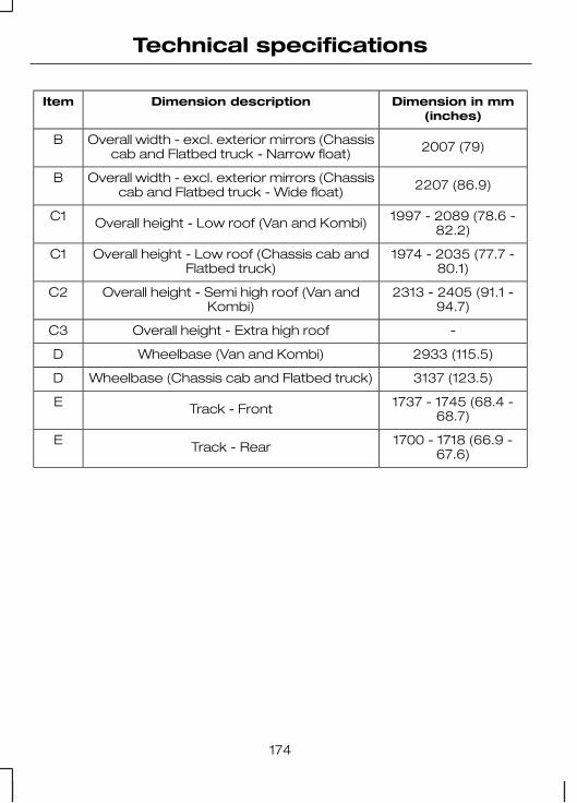
Dimension in mm(inches)
Dimension descriptionItem
2007 (79)Overall width - excl. exterior mirrors (Chassiscab and Flatbed truck - Narrow float)
B
2207 (86.9)Overall width - excl. exterior mirrors (Chassiscab and Flatbed truck - Wide float)
B
1997 - 2089 (78.6 -82.2)Overall height - Low roof (Van and Kombi)C1
1974 - 2035 (77.7 -80.1)
Overall height - Low roof (Chassis cab andFlatbed truck)
C1
2313 - 2405 (91.1 -94.7)
Overall height - Semi high roof (Van andKombi)
C2
-Overall height - Extra high roofC3
2933 (115.5)Wheelbase (Van and Kombi)D
3137 (123.5)Wheelbase (Chassis cab and Flatbed truck)D
1737 - 1745 (68.4 -68.7)Track - FrontE
1700 - 1718 (66.9 -67.6)Track - RearE
174
Technical specifications

Medium wheelbase
E71263
175
Technical specifications

E71264
Dimension in mm(inches)
Dimension descriptionItem
5230 (205.9)Maximum length - without rear step (Van andKombi)
A
5481 (215.8)Maximum length - without rear step (Chassiscab and Flatbed truck without flatbed)
A
5708 (224.7)Maximum length - without rear step (Chassiscab and Flatbed truck with flatbed)
A
5332 (209.9)Maximum length - with rear step (Van andKombi)
A
5373 (211.5)Maximum length - with towing equipment(Van and Kombi)
A
5616 (221.1)Maximum length - with towing equipment
(Chassis cab and Flatbed truck withoutflatbed)
A
5708 (224.7)Maximum length - with towing equipment(Chassis cab and Flatbed truck with flatbed)
A
1974 (77.7)Overall width - excl. exterior mirrors (Van andKombi)
B
176
Technical specifications

Dimension in mm(inches)
Dimension descriptionItem
2007 (79)Overall width - excl. exterior mirrors (Chassiscab and Flatbed truck - Narrow float)
B
2207 (86.9)Overall width - excl. exterior mirrors (Chassiscab and Flatbed truck - Wide float)
B
1995 - 2056 (78.6 -80.9)Overall height - Low roof (Van and Kombi)C1
1969 - 2042 (77.5 -80.4)
Overall height - Low roof (Chassis cab andFlatbed truck)
C1
2310 - 2387 (90.9 -94)
Overall height - Semi high roof (Van andKombi)
C2
2546 - 2617 (100.2 -103)
Overall height - Extra high roof (Van andKombi)
C3
3300 (129.9)Wheelbase (Van and Kombi)D
3504 (138)Wheelbase (Chassis cab and Flatbed truck)D
1737 - 1745 (68.4 -68.7)Track - FrontE
1700 - 1718 (66.9 -67.6)Track - Rear (All with single rear wheels)E
1642 (64.6)Track - Rear (Chassis cab and Flatbed truck- double rear wheels)
E
177
Technical specifications

Long wheelbase
E71265
178
Technical specifications

E71266
Dimension in mm(inches)
Dimension descriptionItem
5680 (223.6)Maximum length - without rear step (Van andKombi)
A
6403 (252.1)Maximum length - without rear step(Extended Frame Van and Kombi)
A
5931 (233.5)Maximum length - without rear step (Chassiscab and Flatbed truck without flatbed)
A
6313 (248.6)Maximum length - without rear step (Chassis
cab and Flatbed truck without flatbed)extended frame
A
6108 (240.5)Maximum length - without rear step (Chassiscab and Flatbed truck with flatbed)
A
6608 (260.2)Maximum length - without rear step (Chassiscab and Flatbed truck with flatbed) extended
frame
A
5782 (227.6)Maximum length - with rear step (Van andKombi)
A
6505 (256.1)Maximum length - with rear step (ExtendedFrame Van and Kombi)
A
179
Technical specifications

Dimension in mm(inches)
Dimension descriptionItem
5823 (229.3)Maximum length - with towing equipment(Van and Kombi)
A
6546 (257.7)Maximum length - with towing equipment(Extended Frame Van and Kombi)
A
6066 (238.8)Maximum length - with towing equipment
(Chassis cab and Flatbed truck withoutflatbed)
A
6448 (253.9)Maximum length - with towing equipment
(Chassis cab and Flatbed truck withoutflatbed) extended frame
A
6108 (240.5)Maximum length - with towing equipment(Chassis cab and Flatbed truck with flatbed)
A
6608 (260.2)Maximum length - with towing equipment
(Chassis cab and Flatbed truck with flatbed)extended frame
A
1974 (77.7)Overall width - excl. exterior mirrors (Van andKombi)
B
2007 (79)Overall width - excl. exterior mirrors (Chassiscab and Flatbed truck - Narrow float)
B
2207 (86.9)Overall width - excl. exterior mirrors (Chassiscab and Flatbed truck - Wide float)
B
2016 - 2031 (79.4 -80)
Overall height - Low roof (Chassis cab andFlatbed truck)
C1
2326 - 2397 (91.6 -94.4)
Overall height - Semi high roof (Van andKombi)
C2
2608 - 2622 (102.7 -103.2)
Overall height - Semi high roof (ExtendedFrame Van and Kombi)
C2
2543 - 2615 (100.1 -103)
Overall height - Extra high roof (Van andKombi)
C3
3750 (147.6)Wheelbase (Van and Kombi)D
180
Technical specifications

Dimension in mm(inches)
Dimension descriptionItem
3954 (155.7)Wheelbase (Chassis cab and Flatbed truck)D
1737 - 1745 (68.4 -68.7)Track - FrontE
1700 - 1718 (66.9 -67.6)Track - Rear (Van and Kombi)E
1642 (64.6)Track - Rear (Chassis cab and Flatbed truck- double rear wheels)
E
181
Technical specifications

Towing equipment dimensions
Van and Kombi
E71267
A
CB
DEF
Dimension in mm(inches)
Dimension descriptionItem
1140 (44.9)Wheel centre - end of towball (StandardFrame)
A
1863 (73.3)Wheel centre - end of towball (ExtendedFrame)
A
182
Technical specifications

Dimension in mm(inches)
Dimension descriptionItem
416 (16.4)Centre of towball - side memberB
832 (32.8)Inner side of side memberC
334 (13.1)Centre of towball - centre 1. attachment pointD
403.5 (15.9)Centre of towball - centre 2. attachment pointE
473 (18.6)Centre of towball - centre 3. attachment pointF
183
Technical specifications

Chassis cab and Flatbed truck
E71268
A
CB
DE
Dimension in mm(inches)
Dimension descriptionItem
1180 (46.5)Wheel centre - end of towball (StandardFrame)
A
1562 (61.5)Wheel centre - end of towball (ExtendedFrame)
A
418 (16.5)Centre of towball - side memberB
184
Technical specifications

Dimension in mm(inches)
Dimension descriptionItem
836 (32.9)Inner side of side memberC
237 (9.3)Centre of towball - centre 1. attachment pointD
343.5 (13.5)Centre of towball - centre 2. attachment pointE
185
Technical specifications

GENERAL INFORMATION
This section describes the functionsand features of the Bluetooth mobilephone and voice control system.
The section covers the followingvariations:
• a mobile phone with a mobilephone cradle without voicecontrol
• a Bluetooth and voice controlsystem with a mobile phonecradle
• a Bluetooth and voice controlsystem without a mobile phonecradle.
The Bluetooth mobile phone part ofthe system provides interaction withthe audio or navigation system andyour mobile phone. It allows you touse the audio or navigation systemto make and receive calls withouthaving to use your mobile phone.
The voice control part of the systemcan be used to control:
• mobile phone calls• audio system functions• vehicle climate control functions.
Note: The mobile phone does notswitch off immediately after theignition key is turned off: the powerdown delay is preset to 10 minutes.The time period can be adjusted tobetween 0 and 60 minutes. This,depending on your mobile phone,can be achieved by creating aphonebook entry on your mobilephone with the name Timer and therequired delay as it's number.
If the Bluetooth and voice control isused for an extended period of timewhen the vehicle is stationary, makesure that the engine is running toavoid draining the battery
TELEPHONE SETUP
Requirements for cradleconnection
Your phone must be fitted in a mobilephone holder before it can be usedas a cradle phone with yourhandsfree/voice control system. Youwill be able to purchase the correctholder for your phone from yourdealer.
Placing your phone in thecradle
Note: Your phone must be fitted ina mobile phone holder to allow youto connect the phone to the cradle.
Connect your phone to the cradle.
1. Place the base of the phone in thecradle connection.
Note: Make sure that the phone ispushed fully rearwards in the cradle.
186
Telephone

2. Push the phone downwards untila click is heard.
2
1
E87688
Note: The connection to the systemwill be displayed on your phone.
Phonebook
After start up access to thephonebook can be delayed for up totwo minutes.
Phonebook categories
Depending on your phonebook entry,different categories can be displayedin the audio or navigation unit.
For example:
MobileM
OfficeO
HomeH
FaxF
Note: Entries may be displayedwithout a category attachment.
The category can also be indicatedas an icon:
Phone
Mobile
Home
Office
Fax
Making a phone an activephone
When using the system for the firsttime, no phone is connected to thesystem.
After switching on the ignition thecradle phone and the Bluetoothphone are recognized differently bythe system.
Bluetooth phone
After bonding a Bluetooth phone tothe system, this becomes the activephone. For further information referto the phone menu.
However, in some cases theBluetooth phone has to be activatedby pressing the appropriate stationbutton on the audio or navigationunit.
Turning the ignition back on again,the last active phone is picked up bythe system.
187
Telephone

Bond another Bluetoothphone
Note: Before another Bluetoothphone can be bonded, the existingactive Bluetooth connection has tobe deactivated by the mobile phone.
Bond a new Bluetooth phone asdescribed in the requirements for aBluetooth connection.
Phones stored in the system areaccessible by using the phone list onthe audio or navigation unit.
Note: If six (five Bluetooth phonesfor cradle phone system) Bluetoothphones have been bonded, one ofthese has to be deleted in order tobond a new phone.
Cradle phone
With your phone fitted in the mobilephone cradle this does notautomatically become the activephone.
In these cases refer to Changingthe active phone in theappropriate section which describesthe system fitted to your vehicle.
BLUETOOTH SETUP
Before you can use your telephonewith your vehicle it must be bondedto the vehicle telephone system.
Handling of phones
A phone can be connected to thevehicle system by using either acradle connection or a Bluetoothconnection.
On vehicles with a mobile phonecradle, up to five Bluetooth phonescan be bonded to the vehicle system.
On vehicles without a mobile phonecradle, up to six Bluetooth phonescan be bonded to the vehicle system.
Note: If there is an ongoing callwhen the phone in use is selected asthe new active phone, the call istransferred to the vehicle audiosystem.
Note: Even if connected to the carsystem, your phone can still be usedin the usual way.
Requirements for Bluetoothconnection
The following are required before aBluetooth phone connection can bemade.
1. The Bluetooth feature must beactivated on the phone and onthe audio unit. For additionalinformation, refer to your phoneuser guide
2. The private mode must not beactivated on the Bluetooth phone.
3. Search for audio device.4. Select Ford Audio.5. The Bluetooth PIN number 0000
must be entered on the phonekeypad.
188
Telephone

Note: A phone call will bedisconnected if the audio/navigationsystem is switched off. If the ignitionkey is turned to the off position thephone call will remain in progress.
Compatibility of phones
CAUTION
As no common agreementexists, mobile phone
manufacturers are able to implementa variety of profiles in their Bluetoothdevices. Because of this, anincompatibility can occur betweenthe phone and hands-free system,which in some cases may significantlydegrade the system performance.To avoid this situation, onlyrecommended phones should beused. Please contact your dealer formore details regarding the currentcompatibility list.
Phones with Symbianoperating system
Note: Certain phones require aspecial file to be installed to enablefull phonebook access via Bluetooth.This is referred to as a SIS file and willbe available via the Ford website.Please consult your dealer for fulldetails.
TELEPHONE CONTROLS
Ending or rejecting calls
By pressing one of several functionbuttons on the audio or navigationunit (example: AM/FM,CD/AUX)active calls can be ended or incomingcalls can be rejected.
Remote control
One of several different types ofremote control may be fitted to yourvehicle:
Voice and mode button
1
2
E87661
Voice button1
Mode button2
Incoming calls can be accepted bypressing the MODE button once orended by pressing twice.
189
Telephone

Voice and accept/reject button
1 2
E87662
Voice button1
Accept/Reject button2
The VOICE button is used to activateor switch off the Voice control.
On vehicles with an accept/rejectbutton, phone calls can be acceptedand rejected by pressing theappropriate button.
Note: Some audio units have theaccept/reject buttons on the frontbezel. These operate in the sameway.
Mode button on the steeringwheel
E87663
Mode button only
E87664
On vehicles without a VOICE button,the MODE button on the remotecontrol is used to activate or switchoff the voice control.
Note: You will not be able to use theMODE button to activate the voicecontrol during an incoming or activecall.
You will not be able to use the MODEbutton to control the audio system.
USING THE TELEPHONE- VEHICLES WITHOUT:NAVIGATION SYSTEM
This chapter describes the phonefunctions of the audio unit.
Note: Refer to your audio guide fordetails of the controls.
An active phone must be present.
Even if connected to the audio unit,your phone can still be used in theusual way.
Note: You can exit the phone menuby pressing any source button CD,AM/FM or AUX.
190
Telephone

Making a call
Dialling a number
You can access your phone addressbook either with the phone dockedin the cradle or via Bluetooth. Theentries will appear in the audio unitdisplay.
1. Press the PHONE or the callaccept button.
2. Press the MENU button.
3. Keep pressing the MENU buttonuntil PHONEBOOK appears.
4. Press the seek buttons to selectthe desired phone number.
Note: Press and hold the seekbutton to skip to the next letter in thealphabet.
5. Press the PHONE or the callaccept button to dial the selectedphone number.
If you have an audio unit with atelephone keypad (buttons 0-9, * and#), you can also direct dial by enteringthe number on the radio display viathe keypad and pressing the callaccept button:
1. Press the call accept button.
2. Dial the number using thetelephone keypad on the audiounit.
3. Press the call accept button.
Note: If you enter an incorrect digitwhilst entering a phone number,press the seek down button to erasethe last digit. A long press will erasethe complete string of digits.
Press and hold 0 to enter a + digit.
Ending a call
Calls can be ended by either:
• pressing one of the followingbuttons on the audio unit:PHONE, CD, AM/FM orON/OFF
• pressing the MODE button onthe remote control
• pressing the call reject button.
Note: If you have an audio unit witha telephone keypad you can end acall only with the call reject button.
Redialling a number
1. Press the PHONE or the callaccept button.
2. Press the MENU button.
3. Select the CALL OUT list or theCALL IN list.
Note: If the active phone does notprovide a call out list, the lastoutgoing call number/entry isdisplayed.
4. Press the seek button on theaudio unit.
5. Press the PHONE or the callaccept button to dial the desiredphone number.
Redialling the last diallednumber
Note: This applies to only audio unitswith a telephone keypad
1. Press the call accept button.
191
Telephone

2. Press the call accept button againto display the last dialled number.
3. Press the call accept button athird time to dial the number.
Receiving an incoming call
Accepting an incoming call
Incoming calls can be accepted byeither:
• pressing the PHONE button• pressing the MODE button on
the remote control• pressing the call accept button.
Rejecting an incoming call
Incoming calls can be rejected byeither:
• pressing the call reject button• pressing the CD button• pressing the AM/FM button.
Note: If you have an audio unit witha telephone keypad you can onlyreject a call with the call reject button.
Note: You cannot reject an incomingcall using the remote control.
Handling a secondincoming call
Note: The second incoming callfunction must be activated in yourphone.
If there is an incoming call whilst thereis an ongoing call, a beep will beheard and you will have the option toend the active call and to accept theincoming call.
Accepting a second incomingcall
Second incoming calls can beaccepted by either:
• pressing the call accept button• pressing the MODE button on
the remote control• pressing the PHONE button.
Note: This will cancel the ongoingcall.
Rejecting a second incomingcall
Second incoming calls can berejected by pressing either:
• pressing the call reject button• pressing the CD button• pressing the AM/FM button.
Note: If you have an audio unit witha telephone keypad you can onlyreject a call with the call reject button.
Changing the active phone
Note: Phones must be bonded tothe system before they can be madeactive.
Using the station storagebutton
1. Press the PHONE button on theaudio unit.
2. Press the preset number required(using the station preset buttons1 - 6).
Note: This process is only for audiounits without a telephone keypad.
192
Telephone

Using the audio unit menu
1. Press the PHONE or call acceptbutton.
2. Press the MENU button on theaudio unit.
3. Select the ACTIVE PHONEoption on the audio unit.
4. Scroll through the different storedphones by using the seek buttonsto display the bonded phones.
5. Press the MENU button to selectthe phone which is to be theactive phone.
Note: After bonding a Bluetoothphone to the system, this becomesthe active phone.
Debonding a bonded phone
A bonded phone can be deletedfrom the system at any time, unlessa phone call is in progress.
1. Press the PHONE or call acceptbutton.
2. Press the MENU button on theaudio unit.
3. Select the DEBOND option onthe audio unit.
4. Scroll through the differentphones by using the seek buttonsand display the phone to bedebonded.
5. Press the MENU button to selectthe phone which is to bedebonded.
USING THE TELEPHONE- TRAVEL PILOT EX
This chapter describes the phonefunctions of the Navigation SystemTravelPilot EX.
Note: Refer to your NavigationSystem TravelPilot EX guide fordetails of the controls.
An active phone must be present.
Even if connected to the NavigationSystem TravelPilot EX, your phonecan still be used in the usual way.
Making a call
Dialling a number - cradlephone
Using the cradle phone allows you toaccess your mobile phone addressbook. The entries will appear in theTravelPilot EX display.
1. Press the PHONE button on theaudio unit.
2. Using the PHONEBOOK optionin the menu.
3. Choose one of the letter areas.
4. Turning the right rotary entrycontrol, select the desired phonenumber.
5. By pressing the INFO button thedetails of the phonebook entrycan be displayed.
6. Press the right rotary entry controlbutton.
193
Telephone

Dialling a number - Bluetoothphone
Using the Bluetooth phone, phonenumbers can be dialled using voicecontrol, refer to the Voice controlchapter.
Ending a call
Calls can be ended by either:
• pressing the reject button• pressing the MODE button on the
remote switch• pressing the off button on the
navigation system• pressing the right rotary entry
control button.
Redialling a number - cradlephone
1. Press the PHONE button on theaudio unit.
2. Press the MENU button.
3. Select the CALL OUT list, CALLIN list or REDIAL.
4. Press the PHONE button on theaudio unit to dial the desiredphone number.
Redialling a number -Bluetooth phone
1. Press the PHONE button on theaudio unit.
2. Press the MENU button.
3. Select REDIAL.
4. Press the PHONE button on theaudio unit to dial the phonenumber.
Handling an incoming call
Accepting an incoming call
Incoming calls can be accepted byeither:
• pressing the accept button• pressing the MODE button on the
remote control• pressing the PHONE button on
the audio unit• using the ACCEPT option in the
menu.
Rejecting an incoming call
Incoming calls can be rejected byeither:
• pressing the reject button• pressing one of the following
buttons on the audio unit: CD,AM/FM
• using the REJECT option in themenu.
Note: You cannot reject an incomingcall using the remote control MODEbutton.
Handling a secondincoming call
Note: The second incoming callfunction must be activated in yourphone.
If there is an incoming call, whilstthere is an ongoing call, a beep willbe heard and you will have the optionto end the active call and to acceptthe incoming call.
194
Telephone

Accepting a second incomingcall
Second incoming calls can beaccepted by either:
• Pressing the accept button.• Pressing the MODE button on the
remote control.• Pressing the PHONE button on
the audio unit.• Using the ACCEPT option in the
menu.
Note: This will cancel the ongoingcall.
Rejecting a second incomingcall
Second incoming calls can berejected by pressing either:
• The teject button• one of the following buttons on
the audio unit: CD, AM/FM.
Changing the active phone
Note: Phones must be bonded tothe system before they can be madeactive.
1. Press the PHONE button on theaudio unit.
2. Using the ACTIVE PHONEoption in the menu, select theactive phone from the list usingthe preset buttons.
Debonding a bonded phone
A bonded phone can be deletedfrom the system at any time, unlessa phone call is in progress.
1. Press the PHONE button on theaudio unit.
2. Select the DEBOND option in themenu.
3. Select the phone from the list byusing the preset buttons.
Note: After bonding a Bluetoothphone to the system, this becomesthe active phone.
However, in some cases theBluetooth phone has to be activatedby pressing the appropriate stationbutton on the audio or navigationunit.
195
Telephone

PRINCIPLE OFOPERATION
Voice recognition enables operationof the audio system without the needto divert your attention from the roadahead in order to change settings, orreceive feedback from the system.
Whenever you issue one of thedefined commands with the systemactive, the voice recognition systemconverts your command into acontrol signal for the audio system.Your inputs take the form ofdialogues or commands. You areguided through these dialogues byannouncements or questions.
Please familiarise yourself with thefunctions of the audio system beforeusing voice recognition.
Note: If the Bluetooth and voicecontrol is used for an extendedperiod of time when the vehicle isstationary, make sure that the engineis running to avoid draining thebattery.
Supported commands
The voice control system allows youto control the following vehiclefunctions:
• phone
• radio
• CD Player
• climate control
• navigation system.
Note: The voice control system islanguage specific. If you require thesystem to operate in anotherlanguage please consult your dealer.
System response
As you work through a voice sessionthe system will prompt you with abeep tone each time the system isready to proceed.
Do not try to give any commandsuntil the beep tone has been heard.The voice control system will repeateach spoken command back to you.
If you are not sure how to continuesay "HELP" for assistance or"CANCEL" if you do not wish tocontinue.
The "HELP" function provides only asubset of the available voicecommands. Detailed explanations ofall possible voice commands can befound on the following pages.
Voice commands
All voice commands should be givenusing a natural speaking voice, as ifspeaking to a passenger or on thephone. Your voice level should bedependant on the surrounding noiselevel inside or outside the vehicle butdo not shout.
Name tag
The name tag functionality cansupport the phone, audio andnavigation features by using the"STORE NAME" function.
196
Voice control

• Store up to 20 name tags perfunction.
• The average recording time foreach name tag is approximately2-3 seconds.
USING VOICE CONTROL
System operation
The order and content of the voicecontrols are given in the followinglists. The tables show the sequenceof user voice commands and systemresponses for each available function.
<> indicates a number or storedname tag to be inserted by the user.
Short cuts
There are a number of voicecommand short cuts available, whichallow you to control some vehiclefeatures without having to follow thecomplete command menu. Theseare:
• phone: "MOBILE NAME"1, "DIALNUMBER", "DIAL NAME" and"REDIAL"
• CD player: "DISC" and "TRACK"• climate control: "TEMPERATURE",
"FAN", "AUTO MODE","DEFROSTING/DEMISTING ON"and "DEFROSTING/DEMISTINGOFF"
• radio: "TUNE NAME"• navigation: "ZOOM" and "ROUTE
SETTING".
1) Only when the mobile phone isfitted with Bluetooth and voicecontrol
Start communicating with thesystem
Before you can start talking to thesystem you first have to press theVOICE or MODE button for eachoperation and wait until the systemanswers with a beep.
E87665
AUDIO UNIT COMMANDS
CD Player/CD Changer
You can choose a disc or trackdirectly by voice control.
197
Voice control

Overview The overview below shows theavailable voice commands foroperating your CD player. Thefollowing lists will give furtherinformation about the completecommand menu.
"CD"
"HELP"
"DISC"a
"TRACK"b
a) Can only be used with a CD changer.
b) Can be used as a shortcut.
Disc
If you have a CD changer you canchoose the disc number.
System answerUser saysSteps
"CD""CD"1
"DISC NUMBER PLEASE""DISC"a2
"DISC <number>""<a number between 1 and 6>"3
a) Can be used as a shortcut.
Track
You can also choose a track on yourCD directly.
System answerUser saysSteps
"CD""CD"1
198
Voice control

System answerUser saysSteps
"TRACK NUMBER PLEASE""TRACK"a2
"TRACK <number>""<a number between 1 and99>"
3
a) Can be used as a shortcut.
Radio
The radio voice commands supportthe functionality of the radio and allowyou to tune radio stations by voicecontrol.
Overview
The overview below shows theavailable voice commands foroperating your radio. The followinglists will give further information aboutthe complete command menu.
"RADIO"
"HELP"
"AM"
"FM"
"TUNE NAME"a
"DELETE NAME"
"DELETE DIRECTORY"
"PLAY DIRECTORY"
"STORE NAME"
a) Can be used as a shortcut.
Tune frequency
This function allows you to tune yourradio by voice commands.
199
Voice control

System answerUser saysSteps
"RADIO""RADIO"1
"FREQUENCY PLEASE""AM"2
"FREQUENCY PLEASE""FM"
"TUNE <frequency>""<frequency>"3
Store name
If you have tuned a radio station, youcan store it with a name in thedirectory.
System answerUser saysSteps
"RADIO""RADIO"1
"STORE NAME""STORE NAME"2"NAME PLEASE"
"REPEAT NAME PLEASE""<name>"3
"STORING NAME""<name>"4"<name> STORED"
Tune name
This function allows you to call up astored radio station.
System answerUser saysSteps
"RADIO""RADIO"1
"NAME PLEASE""TUNE NAME"a2
"TUNE <name>""<name>"3
a) Can be used as a shortcut.
200
Voice control

Delete name This function allows you to delete astored radio station.
System answerUser saysSteps
"RADIO""RADIO"1
"NAME PLEASE""DELETE NAME"2
"DELETE <name>""<name>"3"CONFIRM YES OR NO"
"DELETED""YES"4
"COMMAND CANCELLED""NO"
Play directory
This function allows you to let thesystem tell you all of the stored radiostations.
System answerUser saysSteps
"RADIO""RADIO"1
"PLAY <DIRECTORY>""PLAY DIRECTORY"2
Delete directory
This function allows you to delete allstored radio stations at once.
System answerUser saysSteps
"RADIO""RADIO"1
"DELETE DIRECTORY""DELETE DIRECTORY"2"CONFIRM YES OR NO"
"RADIO DIRECTORY DELETED""YES"3
"COMMAND CANCELLED""NO"
201
Voice control

TELEPHONE COMMANDS
Phone
Your phone system allows you tocreate an additional phonebook. Thestored entries can be dialled by voicecontrol. Phone numbers stored byusing voice control are stored on thevehicle system and not in yourphone.
Overview
The overview below shows theavailable voice commands of thephone system. The following lists willgive further information about thecomplete command menu.
"PHONE"
"HELP"
"MOBILE NAME"a, b
"DIAL NUMBER"a
"DIAL NAME"a
"DELETE NAME"
"DELETE DIRECTORY"
"PLAY DIRECTORY"
"STORE NAME"
"REDIAL"a
"ACCEPT CALLS"
"REJECT CALLS"
a) Can be used as a shortcut.
b) Only possible on mobiles which are connected by Bluetooth and fitted withvoice control and stored name tags.
202
Voice control

Create a phonebook
Store name
New entries can be stored with the"STORE NAME" command. Thisfeature can be used to dial a numberby calling up the name instead of thefull phone number.
System answerUser saysSteps
"PHONE""PHONE"1
"STORE NAME""STORE NAME"2"NAME PLEASE"
"REPEAT NAME PLEASE""<name>"3
"STORING NAME""<name>"4"<name> STORED""NUMBER PLEASE"
"<phone number>""<phone number>"5
"STORING NUMBER""STORE"6"<phone number>"
"NUMBER STORED"
Delete name
Stored names can also be deletedfrom the directory.
System answerUser saysSteps
"PHONE""PHONE"1
"NAME PLEASE""DELETE NAME"2
"DELETE <name>""<name>"3"CONFIRM YES OR NO"
"<name> DELETED""YES"4
"COMMAND CANCELLED""NO"
203
Voice control

Play directory Use this function to let the system tellyou all stored entries.
System answerUser saysSteps
"PHONE""PHONE"1
"PLAY DIRECTORY""PLAY DIRECTORY"2
Delete directory
This function allows you to delete allentries in one go.
System answerUser saysSteps
"PHONE""PHONE"1
"DELETE DIRECTORY""DELETE DIRECTORY"2"CONFIRM YES OR NO"
"PHONE DIRECTORYDELETED"
"YES"3
"COMMAND CANCELLED""NO"
Phone functions
Mobile name
This function allows you to accessphone numbers stored with a nametag in your mobile phone.
System answerUser saysSteps
"PHONE""PHONE"1
"MOBILE NAME" "<phonedependent dialogue>"
"MOBILE NAME"a, b2
a) Can be used as a shortcut.
204
Voice control

b) Only when the mobile phone is fitted with Bluetooth and voice control(dependant on the mobile phone).
Dial number
Phone numbers can be dialled aftergiving the name tag voice command.
System answerUser saysSteps
"PHONE""PHONE"1
"NUMBER PLEASE""DIAL NUMBER"a2
"<phone number>"<phone number>"3CONTINUE?"
"DIALLING""DIAL"4
"<repeat last part of number>"CORRECTION"CONTINUE?"
a) Can be used as a shortcut.
Dial name
Phone numbers can be dialled aftergiving the name tag voice command.
System answerUser saysSteps
"PHONE""PHONE"1
"NAME PLEASE""DIAL NAME"a2
"DIAL <name>""<name>"3"CONFIRM YES OR NO"
"DIALLING""YES"4
"COMMAND CANCELLED""NO"
a) Can be used as a shortcut.
205
Voice control

Redial This function allows you to redial thelast dialled phone number.
System answerUser saysSteps
"PHONE""PHONE"1
"REDIAL""REDIAL"a2"CONFIRM YES OR NO"
"DIALLING""YES"3
"COMMAND CANCELLED""NO"
a) Can be used as a shortcut.
DTMF (Tone dialling)
This function transfers spokennumbers into DTMF tones, i.e. tomake a remote enquiry to your homeanswering machine.
Note: DTMF can only be used duringan ongoing call. Press the VOICEbutton or the MODE button and waitfor the system prompt.
System answerUser saysSteps
"NUMBER PLEASE"1
"<numbers 1 to 9, zero, hash,star>"
2
Main settings
Accept and reject calls
Calls can be accepted or rejectedusing the Voice Control.
System answerUser saysSteps
"PHONE""PHONE"1
"ACCEPT CALLS""ACCEPT CALLS"2
206
Voice control

System answerUser saysSteps
"REJECT CALLS""REJECT CALLS"
NAVIGATION SYSTEMCOMMANDS
Please refer to your separateNavigation handbook for details ofthe command menus.
CLIMATE CONTROLCOMMANDS
Climate
The climate voice commandssupports the functionality of the fanspeed, temperature and modesettings. Not all functions areavailable on all vehicles.
Overview
The overview below shows theavailable voice commands foroperating your climate controlsystem. The following lists will givefurther information about thecomplete command menu.
"CLIMATE"
"HELP"
"FAN"a
"DEFROSTING/DEMISTING ON"a
"DEFROSTING/DEMISTING OFF"a
"TEMPERATURE"a
"AUTO MODE"a
a) Can be used as a shortcut. On vehicles fitted with an English languagemodule the "FAN" shortcut is not available.
207
Voice control

Fan This function allows you to adjust thefan speed.
System answerUser saysSteps
"CLIMATE""CLIMATE"1
"FAN SPEED PLEASE""‘FAN"a2
"FAN MINIMUM""MINIMUM"
3 "FAN <number>""<a number between 1 and 7>"
"FAN MAXIMUM""MAXIMUM"
a) Can be used as a shortcut. On vehicles fitted with an English languagemodule the "FAN" shortcut is not available.
Defrosting/Demisting
System answerUser saysSteps
"CLIMATE""CLIMATE"1
"DEFROSTING/DEMISTING ON""DEFROSTING/DEMISTING
ON"a
2"DEFROSTING/DEMISTING
OFF""DEFROSTING/DEMISTING
OFF"a
a) Can be used as a shortcut.
Temperature
This function allows you to adjust thetemperature.
System answerUser saysSteps
"CLIMATE""CLIMATE"1
"TEMPERATURE PLEASE""TEMPERATURE"a2
208
Voice control

System answerUser saysSteps
"TEMPERATURE MINIMUM""MINIMUM"
3 "TEMPERATURE <number>"
"<a number between 15 and29 °C with 0.5 increments>" or"<a number between 59 and
84 °F>"
"TEMPERATURE MAXIMUM""MAXIMUM"
a) Can be used as a shortcut.
Auto mode
System answerUser saysSteps
"CLIMATE""CLIMATE"1
"AUTO MODE""AUTO MODE"a2
a) Can be used as a shortcut. Can be deactivated by selecting a differenttemperature or fan speed.
209
Voice control

TYPE APPROVALS
Bluetooth/voice recognitionsystem - declaration ofconformity
We, the party responsible forcompliance, declare under our soleresponsibility that the HandsetIntegration product RX-1C is inconformity with the provisions of thefollowing Council Directive:1999/5/EC. A copy of the Declarationof Conformity can be found at:
www.nokia.com/phones/declaration_of_conformity
The Bluetooth word mark and logosare owned by the Bluetooth SIG, Inc.and any use of such marks by FordMotor Company is under license.Other trademarks and trade namesare those of their respective owners.Nokia Corporation Keilalahdentie 4,02150 Espoo, Finland
210
Appendices

AA/C
See: Climate control............................65About this handbook........................5ABS
See: Brakes..........................................94ABS driving hints
See: Hints on driving with ABS..........94Accessories
See: Parts and accessories.................5Air conditioning
See: Climate control............................65Air vents............................................66Alarm.................................................26
Principle of operation..........................26All-wheel drive (AWD).....................92Appendices....................................210Arming the alarm.............................27
Category one alarm............................27Perimeter alarm...................................27
Arming the engine immobiliser.....25Ashtray..............................................80Audible warnings and
indicators........................................56Door open warning.............................56Message centre..................................56
Audio unit commands..................197CD Player/CD Changer.....................197Radio....................................................199
Autolamps........................................33Autowipers.......................................28
Autowipers...........................................28Auxiliary heater................................69
General information.............................69Principle of operation..........................70
Auxiliary power sockets..................81AWD
See: All-wheel drive (AWD)................92
BBattery care....................................144Battery connection points...........146Bluetooth setup.............................188
Compatibility of phones....................189Handling of phones...........................188Requirements for Bluetooth
connection......................................188Bonnet lock
See: Opening and closing thebonnet..............................................130
Booster cablesSee: Using booster cables...............144
Booster cushions..........................150Booster cushion.................................150Booster seat.......................................150
Bottle holder....................................82Brake and clutch fluid check.......137
Topping up..........................................137Brakes...............................................94
Principle of operation..........................94Bulb changing
See: Changing a bulb..........................36Bulb specification chart..................44
CCar wash
See: Cleaning the exterior................142Catalytic converter..........................87
Driving with a catalytic converter......87Parking..................................................88
211
Index

Changing a bulb..............................36Central brake lamp...............................41Front direction indicators....................37Front fog lamps....................................38Front interior lamps.............................42Front reading lamps............................43Headlamp main and dipped
beam..................................................37Number plate lamp..............................41Rear interior lamps..............................43Rear lamps............................................39Rear side lamps....................................41Removing a headlamp.......................36Roof position lamps.............................41Side lamps.............................................37Side marker lamps..............................39Side repeaters......................................38Stepwell lamps.....................................44
Changing a fuse.............................117Changing a road wheel................153
Fitting a wheel.....................................159Front jacking points...........................154Rear jacking points............................156Removing a wheel.............................157Spare wheel........................................153Stowing the wheel.............................160Vehicle jack.........................................154
Changing the vehicle battery......145Changing the wiper blades...........30Checking the wiper blades...........30Child safety.....................................147Child safety locks..........................152Child seat positioning....................148Child seats......................................147
Child restraints for different massgroups..............................................147
Cigar lighter......................................80Cleaning the exterior....................142
Body paintwork preservation...........142Cleaning the chrome trim.................142Cleaning the headlamps...................142Cleaning the rear window................142
Cleaning the interior......................143Seat belts............................................143
Climate control................................65Principle of operation..........................65
Climate control commands........207Climate................................................207
Clock.................................................79Vehicles with high series instrument
cluster................................................79Vehicles with low series instrument
cluster................................................79Coded keys.....................................25Convenience features....................79Coolant check
See: Engine coolant check...............137Cruise control.................................106
Principle of operation........................106Cruise control
See: Using cruise control..................106Cup holders......................................81
DDiesel particulate filter (DPF).........85
Regeneration.......................................85Direction indicators.........................34Disabling the passenger airbag.....17
Disabling the passenger airbag.........18Enabling the passenger airbag..........18
Disarming the alarm........................27Category one alarm............................27Perimeter alarm...................................27
Disarming the engineimmobiliser.....................................25
DPFSee: Diesel particulate filter (DPF).....85
Draining the fuel filter watertrap................................................138Vehicles with a diesel engine...........138
Driving hints.....................................112
212
Index

EElectric exterior mirrors..................47Electric windows.............................46
Opening the driver windowautomatically.....................................46
Emergency equipment.................113Emergency exit..............................113Engine compartment overview.........Engine coolant check...................137
Checking the coolant level...............137Topping up..........................................137
Engine immobiliser..........................25Principle of operation..........................25
Engine oil check.............................136Checking the oil level.........................136Topping up..........................................136
Engine oil dipstick................................Exterior mirrors................................46
FFastening the seat belts.................16First aid kit........................................113
Bus........................................................113Van, Kombi, Chassis cab, Flatbed
truck..................................................113Front fog lamps...............................33Front seats.......................................74
Adjusting the angle of theseatback............................................76
Adjusting the angle of the seatbase...................................................75
Adjusting the armrest..........................76Adjusting the lumbar support............75Moving the seats backwards and
forwards............................................75Fuel and refuelling...........................87
Technical specifications......................89Fuel burning heater
See: Auxiliary heater............................69Fuel consumption
See: .......................................................89Fuel consumption...........................89Fuel cut-off switch.........................114
Resetting the fuel cut-off switch......114Fuel filler flap.....................................88Fuel quality............................................Fuse box locations.........................115
Engine junction box............................116Passenger junction box.....................116Pre-fuse box........................................115Standard relay box.............................115
Fuses................................................115Fuse specification chart................117
Auxiliary fuses.....................................126Engine junction box............................119Passenger junction box....................125Pre-fuse box........................................117Standard relay box............................122
GGauges.............................................49
Engine coolant temperaturegauge.................................................51
Fuel gauge.............................................51High series instrument cluster...........50Low series instrument cluster...........49Odometer, tripmeter and clock.........51
GearboxSee: Transmission...............................92
General information on radiofrequencies.....................................19
Glove box.........................................82
HHandbrake
See: Parking brake..............................95Hazard warning flashers................34Headlamp levelling..........................34
213
Index

Head restraints................................78Adjusting the head restraint...............78Removing the head restraint.............78
Heated seats...................................78Heated windows and mirrors.......69
Heated exterior mirrors......................69Heated windows.................................69
HeatingSee: Climate control............................65
Hill launch assist (HLA)...................98Principle of operation..........................98
Hill launch assistSee: Using HLA....................................98
Hints on driving with ABS...............94HLA
See: Hill launch assist (HLA)...............98See: Using HLA....................................98
IImmobiliser
See: Engine immobiliser.....................25Information displays........................57
General information.............................57Information messages...................59
Warning messages.............................59Inspecting safety system
components.................................114Seat belts.............................................114
Instruments......................................49Interior lamps...................................35
Courtesy lamps - Vehicles withoutinterior sensors.................................35
Courtesy lamp - Vehicles with interiorsensors..............................................35
Reading lamps.....................................36Vehicles with double locking..............35
Interior mirror...................................47Introduction........................................5ISOFIX anchor points.....................151
Attaching a child restraint with a toptether.................................................151
JJump starting
See: Using booster cables...............144
KKeys and remote controls.............19
LLighting control................................32
Headlamp flasher................................32Home safe lighting..............................33Lighting control positions...................32Main and dipped beam......................32Parking lamps.......................................32
Lighting.............................................32Load carriers
See: Roof racks and load carriers.....110Load carrying.................................108
General information...........................108Load retaining fixtures..................108
Securing cargo...................................108Supplementary retaining fixtures.....110
Locking and unlocking...................20Automatic locking................................23Automatic re-locking...........................23Configurable unlocking.......................24Double locking.....................................20Locking and unlocking the doors with
the handles........................................21Locking and unlocking the doors with
the key...............................................20Locking and unlocking the doors with
the remote control...........................21One-stage unlocking..........................23Slam locking.........................................23Two-stage unlocking..........................23Zone re-locking....................................24
Locks................................................20
214
Index

MMaintenance..................................129
General information...........................129Technical specifications....................139
Manual climate control...................66Air conditioning....................................68Air distribution control.........................66Blower....................................................67Defrosting and demisting the
windscreen quickly..........................67Heating the interior quickly.................67Recirculated air....................................67Temperature control...........................66Ventilation..............................................67
Manual transmission.......................92Selecting reverse gear.......................92
Message centreSee: Information displays...................57
MirrorsSee: Heated windows and mirrors....69See: Windows and mirrors.................46
NNavigation system
commands..................................207
OOccupant protection.......................14
Principle of operation...........................14Oil check
See: Engine oil check........................136Opening and closing the
bonnet..........................................130Closing the bonnet............................130Opening the bonnet..........................130
PParking aid.......................................101
Principle of operation.........................101Parking aid
See: Using the parking aid.................101Parking brake..................................95
Applying the parking brake................95Parking on a hill....................................95Releasing the parking brake..............95
Parts and accessories......................5Personalised settings.....................62
Alarm setting........................................63Clock setting........................................62Language setting.................................62Message chimes.................................63Overview of the your settings menu
displays..............................................62Time format..........................................63Units of measure.................................63Your Settings – Exit..............................64Your settings menu.............................62
Power steering fluid check..........138Topping up..........................................138
Programming the remotecontrol.............................................19
QQuick start..........................................6
RRear fog lamps................................33Rear quarter windows...................48Rear seats........................................76
Folding a single seatbackforwards............................................76
Folding the entire seatbackforwards.............................................77
Removing the bench seats................77
215
Index
Rear view camera.........................103Principle of operation........................103
Rear window wiper andwashers..........................................29Intermittent wipe..................................29Rear window washer..........................30Reverse gear wipe..............................30
Reduced engineperformance.................................112
Refuelling..........................................88Remote control programming
See: Programming the remotecontrol................................................19
Repairing minor paintdamage........................................143
Roof racks and load carriers........110Roof rack..............................................110Vehicles with an emergency exit.....110
Running-in.......................................112Brakes and clutch...............................112Engine...................................................112Tyres.....................................................112
SSafety precautions..........................87Seat belt height adjustment...........17
Front seat belt.......................................17Rear seat belt........................................17
Seats.................................................74Sitting in the correct position.........74Sliding windows...............................48Snow chains
See: Using snow chains....................166Speed control
See: Cruise control............................106Stability control................................96
Principle of operation..........................96Stability control
See: Using stability control.................97Starting a diesel engine..................85
Cold or hot engine...............................85
Starting a petrol engine..................84Cold or hot engine...............................84Engine idle speed after starting........84Flooded engine....................................84
Starting the engine.........................84Status after a collision....................114Stepwell lamps................................36Storage compartments.................82
Front storage compartment..............82Overhead storage compartment.....82
Sun visors.........................................79Switching off the engine................86
Vehicles with a turbocharger.............86Symbols glossary..............................5
Symbols in this handbook....................5Symbols on your vehicle.......................5
TTechnical specifications................172
Technical specifications....................172Telephone commands................202
Create a phonebook........................203Main settings......................................206Phone..................................................202Phone functions................................204
Telephone controls.......................189Ending or rejecting calls....................189Remote control..................................189
Telephone setup...........................186Bond another Bluetooth phone......188Making a phone an active phone.....187Phonebook..........................................187Phonebook categories.....................187Placing your phone in the cradle.....186Requirements for cradle
connection......................................186Telephone.......................................186
General information...........................186Telephone
See: Using the telephone.......................See: Using the telephone.......................
216
Index

Ticket holders..................................80Towing a trailer................................111
Steep gradients...................................111Towing points.................................127Towing the vehicle on four
wheels...........................................127Towing..............................................111Traction control..............................100
Principle of operation........................100Traction control
See: Using traction control...............100Transmission....................................92Type approvals..............................210
Bluetooth/voice recognition system- declaration of conformity...........210
Tyre care.........................................166Tyre repair kit..................................160
Checking the tyre pressure.............165General information...........................160Inflating the tyre...................................161Using the tyre repair kit......................161
TyresSee: Wheels and tyres......................153
UUsing booster cables....................144
To connect the booster cables.......144To start the engine.............................145
Using cruise control......................106Cancelling the set speed..................107Changing the set speed...................106Resuming the set speed..................107Setting a speed..................................106Switching cruise control off..............107Switching cruise control on..............106
Using HLA.........................................98Activating the HLA...............................98Deactivating the HLA..........................99Disabling the HLA................................99
Using seat belts duringpregnancy.......................................17
Using snow chains........................166All vehicles...........................................166Front wheel drive vehicles................166
Using stability control......................97Using the parking aid.....................101Using the rear view camera........104
Activating the rear view camera......104Switching the rear view camera on
and off..............................................105Using the display................................105
Using the telephone............................Changing the active phone..............195Debonding a bonded phone...........195Handling an incoming call.................194Handling a second incoming call.....194Making a call.......................................193
Using traction control...................100Using voice control........................197
System operation...............................197Using winter tyres..........................166
VVehicle battery...............................144Vehicle care....................................142Vehicle identification number
(VIN)................................................171Vehicle identification plate.............171Vehicle identification.......................171Vehicle recovery............................127Ventilation
See: Climate control............................65Vents
See: Air vents.......................................66VIN
See: Vehicle identification number(VIN)...................................................171
Voice control..................................196Principle of operation........................196
217
Index

WWarning lamps and indicators......52
ABS warning lamp...............................52Airbag warning lamp...........................52Brake pad wear warning lamp..........53Brake system warning lamp..............53Cruise control indicator......................53Direction indicator................................53Door open warning lamp...................53Engine warning lamps........................53Front fog lamp indicator.....................54Glow plug indicator.............................54Headlamp indicator.............................54High series instrument cluster...........52Hill launch assist indicator...................54Ignition warning lamp..........................54Low fuel level warning lamp...............54Low series instrument cluster...........52Main beam indicator...........................54Message indicator...............................55Oil pressure warning lamp.................55Rear fog lamp indicator......................55Service interval indicator.....................55Shift indicator........................................55Soot overload warning lamp..............55Stability control (ESP) and traction
control warning lamp......................55Water-in-fuel indicator........................56
Warning triangle..............................113Washer fluid check........................139Washers
See: Wipers and washers..................28Washing
See: Cleaning the exterior................142Wheels and tyres..........................153
General information...........................153Technical specifications....................167
Windows and mirrors.....................46Windscreen washers.....................29Windscreen wipers.........................28
Intermittent wipe..................................28
Winter tyresSee: Using winter tyres.....................166
Wipers and washers.......................28
218
Index


Feel the difference
8C1J-19A321-DA(C
G3527en)