For TIG welding - OTC Daihen · For TIG welding-S1- 1. Notes on Safety Before operating this...
40
First thoroughly read this instruction manual to operate the unit correctly. • Installation, maintenance, and repair of this welding torch shall be made by qualified persons or persons who fully understand this welding equipment to secure the safety. • To secure the safety, operation of this welding equipment shall be made by persons who have knowledge and technical skill to fully understand the contents of this manual and handle the equipment. • Regarding safety education, utilize courses and classes held by head/branch offices of the W elding Society /Association and the related societies/associations, and qualifying examinations for welding experts/consultant engineers. • After thoroughly reading this manual, be sure to retain it with the warranty in the place where the persons concerned can read any time. Read it again as necessary. • If incomprehensible, contact our offices. For servicing, contact our local distributor or sales representatives in your country. Our addresses and telephone numbers are listed in the back cover of this Instruction Manual. Contents 1. NOTES ON SAFETY ......................... S1 2. IMPORTANT SAFEGUARDS ............. S2 3. NOTES ON USE ................................ S7 < Operation > 1. Specifications .............................................. 1 2. Checking the Contents of Package ......... 4 3. Mounting/Adjusting Torch and Connecting Shock Sensor Cable .................................. 4 4. Power Cable Hose ..................................... 7 5. Wire Guide (Fe・SUS/AL) .......................... 9 6. Conduit....................................................... 11 7. Setting the Robot Controller ................... 11 8. Function of Major Parts .......................... 13 9. Replacement of Tungsten Electrode .... 17 10 Connection to Welding Power Supply.. 18 11. Requirements........................................... 18 < Maintenance > 12. Troubleshooting ....................................... 19 13. Parts List ................................................... 19 INSTRUCTION MANUAL = Safety and Operation = Instruction Manual No. 1L7620-E-1 MWX-2001 type MWXC-2001 type MWX-3501 type MWXC-3501 type Welding Torch for Robot Power Cable Hose < Shock sensor built-in > For TIG welding
Transcript of For TIG welding - OTC Daihen · For TIG welding-S1- 1. Notes on Safety Before operating this...
First thoroughly read this instruction manual to operate the unit correctly.
• Installation, maintenance, and repair of this
welding torch shall be made by qualified
persons or persons who fully understand this
welding equipment to secure the safety.
• To secure the safety, operation of this welding
equipment shall be made by persons who
have knowledge and technical skill to fully
understand the contents of this manual and
handle the equipment.
• Regarding safety education, utilize courses
and classes held by head/branch offices of
the W elding Society /Association and the
related societies/associations, and qualifying
examinations for welding experts/consultant
engineers.
• After thoroughly reading this manual, be sure
to retain it with the warranty in the place
where the persons concerned can read any
time. Read it again as necessary.
• If incomprehensible, contact our offices. For
servicing, contact our local distributor or sales
representatives in your country.
Our addresses and telephone numbers are listed
in the back cover of this Instruction Manual.
Contents
1. NOTES ON SAFETY ......................... S1
2. IMPORTANT SAFEGUARDS............. S2
3. NOTES ON USE................................ S7
< Operation >
1. Specifications ..............................................1
2. Checking the Contents of Package .........4
3. Mounting/Adjusting Torch and Connecting
Shock Sensor Cable ..................................4
4. Power Cable Hose .....................................7
5. Wire Guide (Fe・SUS/AL)..........................9
6. Conduit.......................................................11
7. Setting the Robot Controller ...................11
8. Function of Major Parts .......................... 13
9. Replacement of Tungsten Electrode .... 17
10 Connection to Welding Power Supply.. 18
11. Requirements........................................... 18
< Maintenance >
12. Troubleshooting ....................................... 19
13. Parts List................................................... 19
INSTRUCTION MANUAL = Safety and Operation = Instruction Manual No.
1L7620-E-1
MWX-2001 type MWXC-2001 type MWX-3501 type MWXC-3501 type
Welding Torch for Robot Power Cable Hose < Shock sensor built-in >
For TIG welding
-S1-
1. Notes on Safety
●Before operating this product, thoroughly read this instruction manual first to operate the product correctly.
●Cautions described in this instruction manual are to prevent you and other people from being injured or damaged by having the product operated correctly and safely.
●Although this product is designed and manufactured in due consideration of safety, carefully follow the notes and cautions described in this manual. Otherwise, there may occur an accident causing serious injury or death.
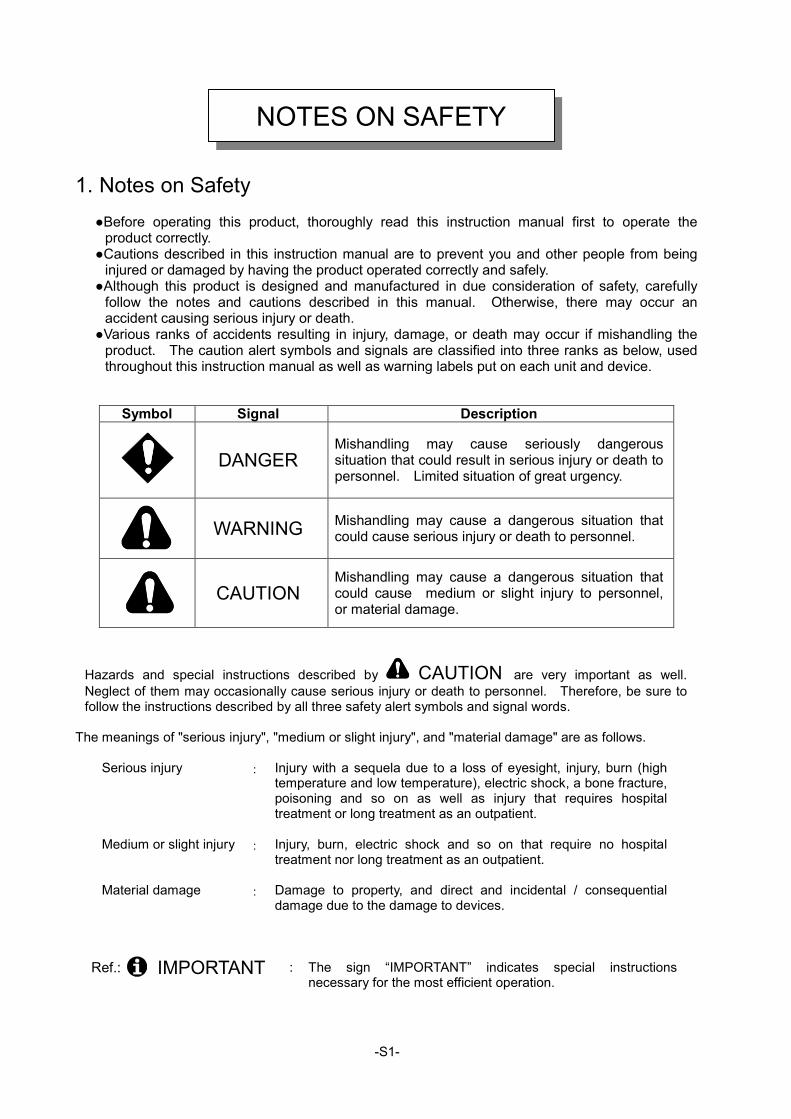
●Various ranks of accidents resulting in injury, damage, or death may occur if mishandling the product. The caution alert symbols and signals are classified into three ranks as below, used throughout this instruction manual as well as warning labels put on each unit and device.
Symbol Signal Description
DANGER Mishandling may cause seriously dangerous situation that could result in serious injury or death to personnel. Limited situation of great urgency.
WARNING Mishandling may cause a dangerous situation that could cause serious injury or death to personnel.
CAUTION
Mishandling may cause a dangerous situation that could cause medium or slight injury to personnel, or material damage.
Hazards and special instructions described by CAUTION are very important as well. Neglect of them may occasionally cause serious injury or death to personnel. Therefore, be sure to follow the instructions described by all three safety alert symbols and signal words.
The meanings of "serious injury", "medium or slight injury", and "material damage" are as follows.
Serious injury : Injury with a sequela due to a loss of eyesight, injury, burn (high temperature and low temperature), electric shock, a bone fracture, poisoning and so on as well as injury that requires hospital treatment or long treatment as an outpatient.
Medium or slight injury : Injury, burn, electric shock and so on that require no hospital treatment nor long treatment as an outpatient.
Material damage : Damage to property, and direct and incidental / consequential damage due to the damage to devices.
Ref.: IMPORTANT : The sign “IMPORTANT” indicates special instructions necessary for the most efficient operation.
NOTES ON SAFETY
-S2-
2. Important Safeguard 2.1 Read, understand, and comply with all safety rules described at the beginning of
each instruction manual in addition to the following ones before starting Arc welding operation.
WARNING Observe the following notices to prevent a serious accident that results in serious injury or death.
1) This torch is designed and manufactured in due consideration of safety, but you must follow
the handling precautions described in this instruction manual. If you fail to do so, there may occur an accident resulting in serious injury or death.
2) Related laws, regulations, and your company's standards should be observed in constructing input power source, selecting an installation area, handling/storing/piping high pressure gas, storing welded products, and disposing wastes.
3) Keep out of the robot operating zone and the welding area. 4) A person with pacemaker should not approach the operating welding machine and the welding
area unless his or her doctor permits. A welding machine generates a magnetic field around it during powered, which will have a bad effect on the pacemaker.
5) Installation, maintenance, and repair of this torch should be performed by qualified personnel or those who fully understand a welding torch for further safety.
6) Operation of this torch should be done by personnel who have knowledge and technical skill to fully understand the contents of this manual and to handle the torch safely.
7) This torch must not be used for purposes other than welding.
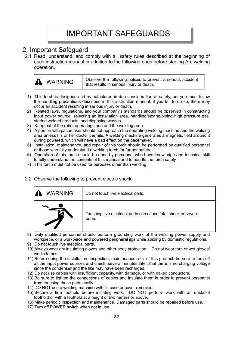
2.2 Observe the following to prevent electric shock.
WARNING Do not touch live electrical parts.
Touching live electrical parts can cause fatal shock or severe burns.
8) Only qualified personnel should perform grounding work of the welding power supply and workpiece, or a workpiece and powered peripheral jigs while abiding by domestic regulations.
9) Do not touch live electrical parts. 10) Always wear dry insulating gloves and other body protection. Do not wear torn or wet gloves/
work clothes. 11) Before doing the installation, inspection, maintenance, etc. of this product, be sure to turn off
all the input power sources and check, several minutes later, that there is no charging voltage since the condenser and the like may have been recharged.
12) Do not use cables with insufficient capacity, with damage, or with naked conductors. 13) Be sure to tighten the connections of cables and insulate them in order to prevent personnel
from touching those parts easily. 14) DO NOT use a welding machine with its case or cover removed. 15) Secure a firm foothold before initiating work. DO NOT perform work with an unstable
foothold or with a foothold at a height of two meters or above. 16) Make periodic inspection and maintenance. Damaged parts should be repaired before use. 17) Turn off POWER switch when not in use.
IMPORTANT SAFEGUARDS
-S3-
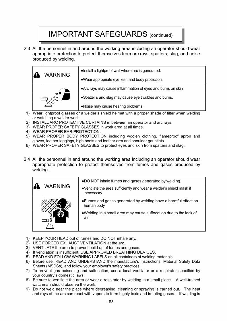
2.3 All the personnel in and around the working area including an operator should wear appropriate protection to protect themselves from arc rays, spatters, slag, and noise produced by welding.
●Install a lightproof wall where arc is generated.
WARNING ●Wear appropriate eye, ear, and body protection.
●Arc rays may cause inflammation of eyes and burns on skin
●Spatter s and slag may cause eye troubles and burns.
●Noise may cause hearing problems.
1) Wear lightproof glasses or a welder’s shield helmet with a proper shade of filter when welding or watching a welder work.
2) INSTALL ARC PROTECTIVE CURTAINS in between an operator and arc rays. 3) WEAR PROPER SAFETY GLASSES in work area at all times. 4) WEAR PROPER EAR PROTECTION. 5) WEAR PROPER BODY PROTECTION including woolen clothing, flameproof apron and
gloves, leather leggings, high boots and leather arm and shoulder gauntlets. 6) WEAR PROPER SAFETY GLASSES to protect eyes and skin from spatters and slag.
2.4 All the personnel in and around the working area including an operator should wear appropriate protection to protect themselves from fumes and gases produced by welding.
●DO NOT inhale fumes and gases generated by welding.
WARNING ●Ventilate the area sufficiently and wear a welder’s shield mask if necessary.
●Fumes and gases generated by welding have a harmful effect on human body.
●Welding in a small area may cause suffocation due to the lack of air.
1) KEEP YOUR HEAD out of fumes and DO NOT inhale any. 2) USE FORCED EXHAUST VENTILATION at the arc. 3) VENTILATE the area to prevent build-up of fumes and gases. 4) If ventilation is insufficient, USE APPROVED BREATHING DEVICES. 5) READ AND FOLLOW WARNING LABELS on all containers of welding materials. 6) Before use, READ AND UNDERSTAND the manufacture's instructions, Material Safety Data
Sheets (MSDSs), and follow your employer's safety practices. 7) To prevent gas poisoning and suffocation, use a local ventilator or a respirator specified by
your country’s domestic laws. 8) Be sure to ventilate the area or wear a respirator by welding in a small place. A well-trained
watchman should observe the work. 9) Do not weld near the place where degreasing, cleaning or spraying is carried out. The heat
and rays of the arc can react with vapors to form highly toxic and irritating gases. If welding is
IMPORTANT SAFEGUARDS (continued)

-S4-
carried out there, harmful gases may be produced. 10) Toxic fumes and gases are produced when coated steel is welded. Be sure to ventilate the
area sufficiently or use a respirator.
-S5-
2.5 Prevent fire, explosion, burns and injury caused by heated workpiece, spatters, slag,
and arc sparks right after welding as described below.
●Do not weld near flammable materials.
●Watch for fire: keep a fire extinguisher nearby.
●NEVER do welding on inflammables such as a piece of wood or cloth.
WARNING
●Do not weld on closed containers.
●Heated workpiece, spatters, slag and arc sparks right after welding may cause fire.
●Incomplete cable connections, incomplete contacts in the current circuit of the workpiece such as steel frames may cause a fire due to the heat generated when powered.
●Arc generated on containers of inflammables such as gasoline may cause an explosion.
●Welding of airtight tanks and pipes may cause a bursting.
●Touching a heated workpiece, spatters, slag or arc sparks will cause a serious burn.
1) KEEP FLAMMBLE MATERIALES out of the robotic cell. 2) Welders should wear appropriate protection such as flameproof leather gloves, work clothes
with long sleeves, a leg cover, a flameproof leather apron in order to prevent burns caused by touching heated workpiece, spatters, slag and arc sparks right after welding..
3) WATCH for fire. 4) Have a fire extinguisher nearby. Operators should know how to use it. 5) DO NOT touch heated workpiece and peripheral jigs with inflammables such as a piece of wood
or cloth. Doing so might cause not only a fire but also burns. 6) DO NOT put heated workpiece close to inflammables right after welding. 7) Remove inflammables from the place where welding is carried out so that spatters and slag will
not strike them. 8) Do not use inflammable gases near the welding sight. 9) Tighten and insulate the cable connections completely. 10) Connect the cables on the workpiece side as close to the welding area as possible to prevent
the welding current from traveling along unknown paths and causing electric shock and fire hazards.
11) A gas pipe with gas sealed in, an airtight tank and a pipe must not be welded because they might explode.
12) NEVER do welding on inflammables such as a piece of wood or cloth. 13) When welding a large-size structure such as a ceiling, floor, wall, etc., remove any inflammables
hidden behind a workpiece.
IMPORTANT SAFEGUARDS (continued)
-S6-
For reference
PRINCIPAL SAFETY STANDARDS
Safety in Welding and Cutting, ANSI Standard Z49.1, from American Welding Society. Safety and Health Standards, OSHA 29 CFR 1910, from Superintendent of Documents, U.S. Government Printing Office. Recommended Practices for Plasma Arc Cutting, American Welding Society Standard AWS C5.2, from American Welding Society. Recommended Safe Practices for the Preparation for Welding and Cutting of Containers That Have Held Hazardous Substances, American Welding Society Standard AWS F4.1, from American Welding Society. National Electrical Code, NFPA Standard 70, from National Fire Protection Association. Safe Handling of Compressed Gases in Cylinders, CGA Pamphlet P-1, from Compressed Gas Association. Code for Safety in Welding and Cutting, CSA Standard W117.2, from Canadian Standards Association, Standards Sales. Safe Practices For Occupation And Educational Eye And Face Protection, ANSI Standard Z87.1, from American National Standards Institute. Cutting And Welding Processes, NFPA Standard 51B, from National Fire Protection Association.
IMPORTANT SAFEGUARDS (continued)
-S7-
3. Notes on Use
3.1 Cooling water
CAUTION
● Be sure to flow 1.2l/min or more of cooling water. (The water pressure at the torch inlet shall be 0.1 ~ 0.3MPa or higher.) Insufficient amount of running water may lead to damage of torch.
● Do not use the water-cooling torch with air cooling. ● Do not use a leaky welding torch as you may get an electric shock.
CAUTION ● Before use, make sure that the electrode is stuck out of the nozzle tip by 5 ~ 10mm. The nozzle may get damaged by arc heat if the electrode tip remains inside the nozzle.
3.2 Cable hose
CAUTION ● Do not let cable hoses touch any heated part of the welded, put something heavy on top nor bend them excessively because the welding torch might become damaged.
3.3 Replacement of Parts
CAUTION ● To prevent burns, comply with the following cautions.
● Do not directly touch the high-temperature parts of a nozzle, an electrode and so on. ● When welding, wear suitable protection such as leather gloves for welding. ● Do not replace torch tip elements before they cool off.
CAUTION ● If any parts are damaged, replace them with new ones for further safety and better quality.
●Be sure to place an order for replacement parts at our sales office or our agency.
CAUTION ● When grinding the electrode, be sure to wear the protective glasses to protect your eyes.
●When you perform the grinding operation, follow the safety measures for grinder or electrode grinding machine.
CAUTION ● Be sure to turn off the servo power of the robot before replacing or cleaning the parts (replacement of electrode, torch, etc.).
NOTES ON USE
-1-
This instruction manual describes the operation and maintenance of DAIHEN TIG Welding Torch. Before using your torch, carefully read and understand the entire contents of this manual so as to handle and operate the torch properly and safely. Before operating the torch, be sure to read OPERATION.
Note 1 : The contents of this instruction manual are subject to change without prior notice.
2 : This instruction manual has been prepared and printed properly and correctly to the best of our knowledge.
Errors and omissions shall be excepted, and in any event, we shall not be held responsible therefore.
3 : This instruction manual shall not be reproduced in whole or in part, in any form or by any means whatsoever
without prior permission.
Characteristics
● In an arc welding robot, welding torch may contact a workpiece or jig, deforming the welding torch or
damaging the robot main unit. To prevent such accident in case external force exceeding a specified
value is applied to the tip (nozzle) of the torch, a shock sensor is incorporated in this welding torch so
as to clear the nozzle by external force and output external force detection signal while the nozzle is
being cleared, thereby enabling the robot main unit to stop immediately.
● Double collet is used for providing high electrode holding force and stabilized feeding.
● Rear collet body assembly can be separated from the torch main unit. To reduce the electrode
replacement time, prepare two or more rear collet body assemblies equipped with new electrodes.
● Wire extension can be easily set when an option electrode adjusting gauge is used.
Operation
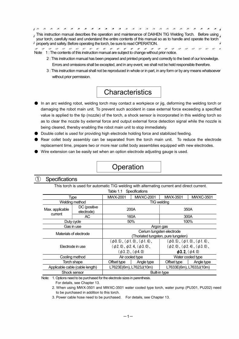
① Specifications This torch is used for automatic TIG welding with alternating current and direct current.
Table 1.1 Specifications
Type MWX-2001 MWXC-2001 MWX-3501 MWXC-3501
Welding method TIG welding
DC (positive electrode)
200A 350A Max. applicable current
AC 160A 300A
Duty cycle 50% 100%
Gas in use Argon gas
Materials of electrode Cerium tungsten electrode
(Thoriated tungsten, pure tungsten)
Electrode in use
(φ0.5)、(φ1.0)、(φ1.6)、
(φ2.0)、φ2.4、(φ3.0)、
(φ3.2)、(φ4.0)
(φ0.5)、(φ1.0)、(φ1.6)、
(φ2.0)、(φ2.4)、(φ3.0)、
φ3.2φ3.2φ3.2φ3.2、(φ4.0)
Cooling method Air cooled type Water cooled type
Torch shape Offset type Angle type Offset type Angle type
Applicable cable (cable length) L7623E(6m)、L7623J(10m) L7633E(6m)、L7633J(10m)
Shock sensor Built-in type
Note: 1. Options need to be purchased for the electrode sizes in parenthesis.
For details, see Chapter 13.
2. When using MWX-3501 and MWXC-3501 water cooled type torch, water pump (PU301, PU202) need
to be purchased in addition to this torch.
3. Power cable hose need to be purchased. For details, see Chapter 13.
-2-
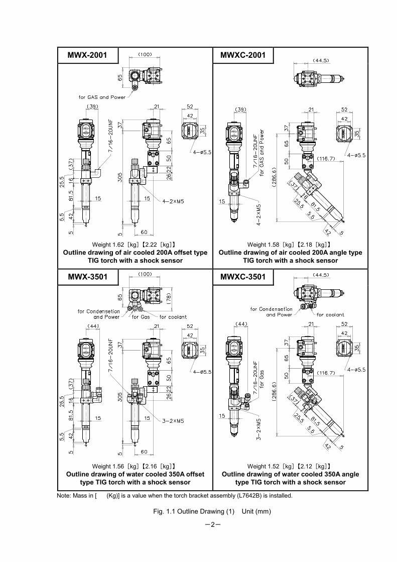
Note: Mass in [ (Kg)] is a value when the torch bracket assembly (L7642B) is installed.
Fig. 1.1 Outline Drawing (1) Unit (mm)
MWX-2001 MWXC-2001
Weight 1.62[kg]【2.22[kg]】
Outline drawing of air cooled 200A offset type
TIG torch with a shock sensor
Weight 1.58[kg]【2.18[kg]】
Outline drawing of air cooled 200A angle type
TIG torch with a shock sensor
MWX-3501 MWXC-3501
Weight 1.56[kg]【2.16[kg]】
Outline drawing of water cooled 350A offset
type TIG torch with a shock sensor
Weight 1.52[kg]【2.12[kg]】
Outline drawing of water cooled 350A angle
type TIG torch with a shock sensor
-3-
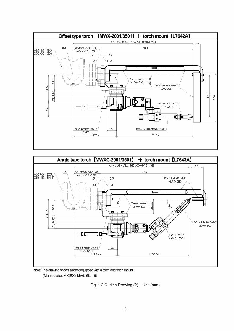
Offset type torch 【【【【MWX-2001/3501】+】+】+】+ torch mount【【【【L7642A】】】】
Angle type torch【【【【MWXC-2001/3501】】】】 ++++ torch mount【【【【L7643A】】】】
Note: This drawing shows a robot equipped with a torch and torch mount.
(Manipulator: AX(EX)-MV6, 6L, 16)
Fig. 1.2 Outline Drawing (2) Unit (mm)
-4-
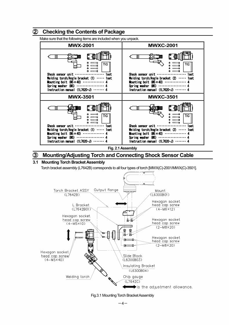
②②②② Checking the Contents of Package
Make sure that the following items are included when you unpack.
MWX-2001 MWXC-2001
Shock sensor unit Shock sensor unit Shock sensor unit Shock sensor unit ・・・・・・・・・・・・・・・・・・・・・・・・・・・・・・・・・・・・・・・・・・・・・・・・・・・・・・・・・・・・・・・・・・・・・・・・・・・・ 1set 1set 1set 1set Welding torch/Angle bracket (1)Welding torch/Angle bracket (1)Welding torch/Angle bracket (1)Welding torch/Angle bracket (1) ・・・・・・・・・・・・・・・・・・・・ 1set 1set 1set 1set Mounting bolt (M5Mounting bolt (M5Mounting bolt (M5Mounting bolt (M5××××40) 40) 40) 40) ・・・・・・・・・・・・・・・・・・・・・・・・・・・・・・・・・・・・・・・・・・・・・・・・・・・・・・・・ 4 4 4 4 Spring washer (M5) Spring washer (M5) Spring washer (M5) Spring washer (M5) ・・・・・・・・・・・・・・・・・・・・・・・・・・・・・・・・・・・・・・・・・・・・・・・・・・・・・・・・・・・・・・・・・・・・・・・・ 4 4 4 4 Instruction manualInstruction manualInstruction manualInstruction manual((((1L76201L76201L76201L7620----JJJJ))))・・・・・・・・・・・・・・・・・・・・・・・・・・・・ 4 4 4 4
Shock sensor unit Shock sensor unit Shock sensor unit Shock sensor unit ・・・・・・・・・・・・・・・・・・・・・・・・・・・・・・・・・・・・・・・・・・・・・・・・・・・・・・・・・・・・・・・・・・・・・・・・・・・・ 1set 1set 1set 1set Welding torch/Angle bracket (2)Welding torch/Angle bracket (2)Welding torch/Angle bracket (2)Welding torch/Angle bracket (2) ・・・・・・・・・・・・・・・・・・・・ 1set 1set 1set 1set Mounting bolt (M5Mounting bolt (M5Mounting bolt (M5Mounting bolt (M5××××40) 40) 40) 40) ・・・・・・・・・・・・・・・・・・・・・・・・・・・・・・・・・・・・・・・・・・・・・・・・・・・・・・・・ 4 4 4 4 Spring washer (M5) Spring washer (M5) Spring washer (M5) Spring washer (M5) ・・・・・・・・・・・・・・・・・・・・・・・・・・・・・・・・・・・・・・・・・・・・・・・・・・・・・・・・・・・・・・・・・・・・・・・・ 4 4 4 4 Instruction manualInstruction manualInstruction manualInstruction manual((((1L76201L76201L76201L7620----JJJJ))))・・・・・・・・・・・・・・・・・・・・・・・・・・・・ 4 4 4 4
MWX-3501 MWXC-3501
Shock sensor unit Shock sensor unit Shock sensor unit Shock sensor unit ・・・・・・・・・・・・・・・・・・・・・・・・・・・・・・・・・・・・・・・・・・・・・・・・・・・・・・・・・・・・・・・・・・・・・・・・・・・・ 1set 1set 1set 1set Welding torch/AnglWelding torch/AnglWelding torch/AnglWelding torch/Angle bracket (1)e bracket (1)e bracket (1)e bracket (1) ・・・・・・・・・・・・・・・・・・・・ 1set 1set 1set 1set Mounting bolt (M5Mounting bolt (M5Mounting bolt (M5Mounting bolt (M5××××40) 40) 40) 40) ・・・・・・・・・・・・・・・・・・・・・・・・・・・・・・・・・・・・・・・・・・・・・・・・・・・・・・・・ 4 4 4 4 Spring washer (M5) Spring washer (M5) Spring washer (M5) Spring washer (M5) ・・・・・・・・・・・・・・・・・・・・・・・・・・・・・・・・・・・・・・・・・・・・・・・・・・・・・・・・・・・・・・・・・・・・・・・・ 4 4 4 4 Instruction manualInstruction manualInstruction manualInstruction manual((((1L76201L76201L76201L7620----JJJJ))))・・・・・・・・・・・・・・・・・・・・・・・・・・・・ 4 4 4 4
Shock sensor unit Shock sensor unit Shock sensor unit Shock sensor unit ・・・・・・・・・・・・・・・・・・・・・・・・・・・・・・・・・・・・・・・・・・・・・・・・・・・・・・・・・・・・・・・・・・・・・・・・・・・・ 1set 1set 1set 1set Welding torch/Angle bracket (2)Welding torch/Angle bracket (2)Welding torch/Angle bracket (2)Welding torch/Angle bracket (2) ・・・・・・・・・・・・・・・・・・・・ 1set 1set 1set 1set Mounting bolt (M5Mounting bolt (M5Mounting bolt (M5Mounting bolt (M5××××40)40)40)40) ・・・・・・・・・・・・・・・・・・・・・・・・・・・・・・・・・・・・・・・・・・・・・・・・・・・・・・・・ 4 4 4 4 Spring washer (M5) Spring washer (M5) Spring washer (M5) Spring washer (M5) ・・・・・・・・・・・・・・・・・・・・・・・・・・・・・・・・・・・・・・・・・・・・・・・・・・・・・・・・・・・・・・・・・・・・・・・・ 4 4 4 4 Instruction manualInstruction manualInstruction manualInstruction manual((((1L76201L76201L76201L7620----JJJJ))))・・・・・・・・・・・・・・・・・・・・・・・・・・・・ 4 4 4 4
Fig. 2.1 Assembly
③③③③ Mounting/Adjusting Torch and Connecting Shock Sensor Cable
3.1 Mounting Torch Bracket Assembly
Torch bracket assembly (L7642B) corresponds to all four types of torch [MWX(C)-2001/MWX(C)-3501].
Fig.3.1 Mounting Torch Bracket Assembly
-5-
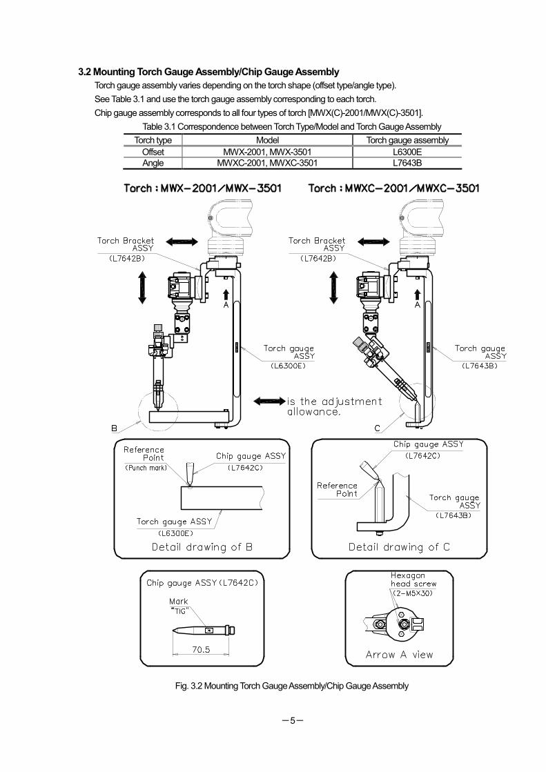
3.2 Mounting Torch Gauge Assembly/Chip Gauge Assembly
Torch gauge assembly varies depending on the torch shape (offset type/angle type).
See Table 3.1 and use the torch gauge assembly corresponding to each torch.
Chip gauge assembly corresponds to all four types of torch [MWX(C)-2001/MWX(C)-3501].
Table 3.1 Correspondence between Torch Type/Model and Torch Gauge Assembly
Torch type Model Torch gauge assembly
Offset MWX-2001, MWX-3501 L6300E
Angle MWXC-2001, MWXC-3501 L7643B
Fig. 3.2 Mounting Torch Gauge Assembly/Chip Gauge Assembly
-6-
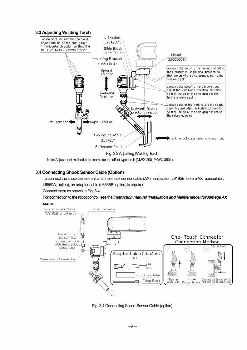
3.3 Adjusting Welding Torch
Fig. 3.3 Adjusting Welding Torch
Note: Adjustment method is the same for the offset type torch (MWX-2001/MWX-3501).
3.4 Connecting Shook Sensor Cable (Option)
To connect the shock sensor unit and the shock sensor cable (AX manipulator: L9195B, before AX manipulator:
L6569A; option), an adapter cable (L6635B: option) is required.
Connect them as shown in Fig. 3.4.
For connection to the robot control, see the instruction manual (Installation and Maintenance) for Almega AX
series.
Fig. 3.4 Connecting Shock Sensor Cable (option)
-7-
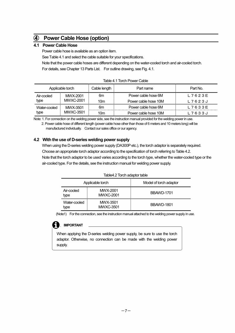
④④④④ Power Cable Hose (option)
4.1 Power Cable Hose
Power cable hose is available as an option item.
See Table 4.1 and select the cable suitable for your specifications.
Note that the power cable hoses are different depending on the water-cooled torch and air-cooled torch.
For details, see Chapter 13 Parts List. For outline drawing, see Fig. 4.1.
Table 4.1 Torch Power Cable
Applicable torch Cable length Part name Part No.
6m Power cable hose 6M L7623E Air-cooled type
MWX-2001 MWXC-2001 10m Power cable hose 10M L7623J
6m Power cable hose 6M L7633E Water-cooled type
MWX-3501 MWXC-3501 10m Power cable hose 10M L7633J
Note: 1. For connection on the welding power side, see the instruction manual provided for the welding power in use.
2. Power cable hose of different length (power cable hose other than those of 6 meters and 10 meters long) will be
manufactured individually. Contact our sales office or our agency.
4.2 With the use of D-series welding power supply
When using the D-series welding power supply (DA300P etc.), the torch adaptor is separately required.
Choose an appropriate torch adaptor according to the specification of torch referring to Table 4.2.
Note that the torch adaptor to be used varies according to the torch type, whether the water-cooled type or the
air-cooled type. For the details, see the instruction manual for welding power supply.
Table4.2 Torch adaptor table
Applicable torch Model of torch adaptor
Air-cooled type
MWX-2001 MWXC-2001
BBAWD-1701
Water-cooled type
MWX-3501 MWXC-3501
BBAWD-1801
(Note1) For the connection, see the instruction manual attached to the welding power supply in use.
When applying the D-series welding power supply, be sure to use the torch
adaptor. Otherwise, no connection can be made with the welding power
supply.
IMPORTANT
-8-
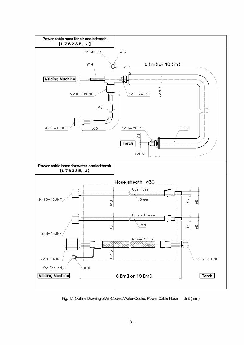
Power cable hose for air-cooled torch
【L【L【L【L7623762376237623E,J】E,J】E,J】E,J】
Power cable hose for water-cooled torch 【L【L【L【L7633763376337633E,J】E,J】E,J】E,J】
Fig. 4.1 Outline Drawing of Air-Cooled/Water-Cooled Power Cable Hose Unit (mm)
-9-
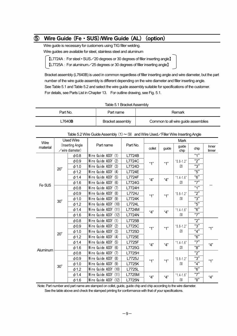
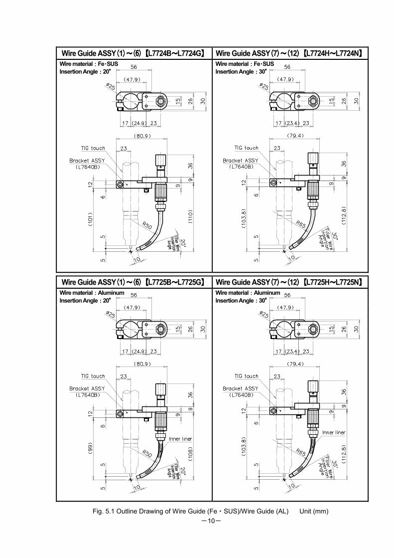
⑤⑤⑤⑤ Wire Guide ((((Fe・・・・SUS))))/Wire Guide ((((AL) () () () (option)))) Wire guide is necessary for customers using TIG filler welding.
Wire guides are available for steel, stainless steel and aluminum
【L7724A:For steel • SUS/20 degrees or 30 degrees of filler inserting angle】
【L7725A:For aluminum/25 degrees or 30 degrees of filler inserting angle】
Bracket assembly (L7640B) is used in common regardless of filler inserting angle and wire diameter, but the part
number of the wire guide assembly is different depending on the wire diameter and filler inserting angle.
See Table 5.1 and Table 5.2 and select the wire guide assembly suitable for specifications of the customer.
For details, see Parts List in Chapter 13. For outline drawing, see Fig. 5.1.
Table 5.1 Bracket Assembly
Part No. Part name Remark
L7640B Bracket assembly Common to all wire guide assemblies
Table 5.2 Wire Guide Assembly (1)~(9) and Wire Used/Filler Wire Inserting Angle
Mark Wire
material
Used Wire (Inserting Angle
/wire diameter)
Part name Part No. collet guide
guide chip
chip Inner linner
φ0.8 Wire Guide ASSY (1) L7724B “1”
φ0.9 Wire Guide ASSY (2) L7724C “2”
φ1.0 Wire Guide ASSY (3) L7724D “3”
φ1.2 Wire Guide ASSY (4) L7724E
“1” “1” “ 0 . 8 - 1 . 2 ”
/20
“5”
φ1.4 Wire Guide ASSY (5) L7724F “6”
20°
φ1.6 Wire Guide ASSY (6) L7724G “4” “4”
“ 1 . 4 - 1 . 6 ”
/20 “7”
φ0.8 Wire Guide ASSY (7) L7724H “1”
φ0.9 Wire Guide ASSY (8) L7724J “2”
φ1.0 Wire Guide ASSY (9) L7724K “3”
φ1.2 Wire Guide ASSY (10) L7724L
“1” “1” “ 0 . 8 - 1 . 2 ”
/30
“5”
φ1.4 Wire Guide ASSY (11) L7724M “6”
Fe・SUS
30°
φ1.6 Wire Guide ASSY (12) L7724N “4” “4”
“ 1 . 4 - 1 . 6 ”
/30 “7”
-
φ0.8 Wire Guide ASSY (1) L7725B “2”
φ0.9 Wire Guide ASSY (2) L7725C “3”
φ1.0 Wire Guide ASSY (3) L7725D “4”
φ1.2 Wire Guide ASSY (4) L7725E
“1” “1” “ 0 . 8 - 1 . 2 ”
/20
“6”
“1”
φ1.4 Wire Guide ASSY (5) L7725F “7”
20°
φ1.6 Wire Guide ASSY (6) L7725G “4” “4”
“ 1 . 4 - 1 . 6 ”
/20 “8” “4”
φ0.8 Wire Guide ASSY (7) L7725H “2”
φ0.9 Wire Guide ASSY (8) L7725J “3”
φ1.0 Wire Guide ASSY (9) L7725K “4”
φ1.2 Wire Guide ASSY (10) L7725L
“1” “1” “ 0 . 8 - 1 . 2 ”
/30
“6”
“1”
φ1.4 Wire Guide ASSY (11) L7725M “7”
Aluminum
30°
φ1.6 Wire Guide ASSY (12) L7725N “4” “4”
“ 1 . 4 - 1 . 6 ”
/30 “8” “4”
Note: Part number and part name are stamped on collet, guide, guide chip and chip according to the wire diameter.
See the table above and check the stamped printing for conformance with that of your specifications.
-10-
Wire Guide ASSY((((1))))~~~~(6(6(6(6))))【【【【L7724B~~~~L7724G】】】】 Wire Guide ASSY((((7))))~~~~((((12))))【【【【L7724H~~~~L7724N】】】】
Wire material::::Fe・・・・SUS
Insertion Angle::::20°°°° Wire material::::Fe・・・・SUS
Insertion Angle::::30°°°°
Wire Guide ASSY((((1))))~~~~(6(6(6(6))))【【【【L7725B~~~~L7725G】】】】 Wire Guide ASSY((((7))))~~~~((((12))))【【【【L7725H~~~~L7725N】】】】
Wire material::::Aluminum
Insertion Angle::::20°°°° Wire material::::Aluminum
Insertion Angle::::30°°°°
Fig. 5.1 Outline Drawing of Wire Guide (Fe・SUS)/Wire Guide (AL) Unit (mm)
-11-
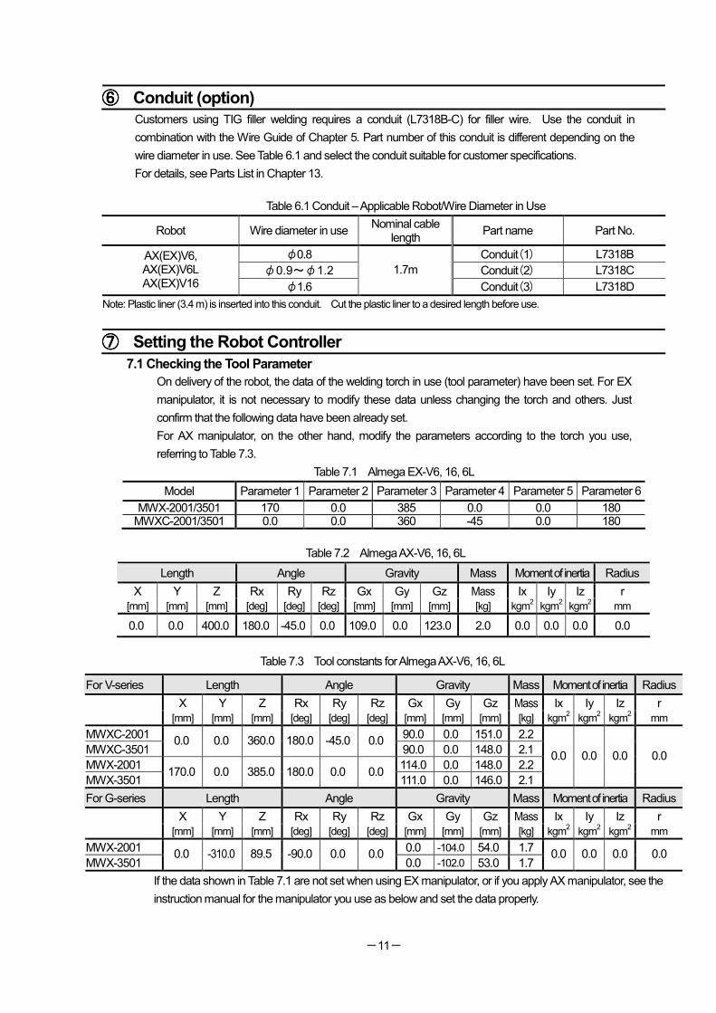
⑥⑥⑥⑥ Conduit (option)
Customers using TIG filler welding requires a conduit (L7318B-C) for filler wire. Use the conduit in
combination with the Wire Guide of Chapter 5. Part number of this conduit is different depending on the
wire diameter in use. See Table 6.1 and select the conduit suitable for customer specifications.
For details, see Parts List in Chapter 13.
Table 6.1 Conduit – Applicable Robot/Wire Diameter in Use
Robot Wire diameter in use Nominal cable
length Part name Part No.
φ0.8 Conduit(1) L7318B
φ0.9~φ1.2 Conduit(2) L7318C
AX(EX)V6, AX(EX)V6L AX(EX)V16 φ1.6
1.7m
Conduit(3) L7318D
Note: Plastic liner (3.4 m) is inserted into this conduit. Cut the plastic liner to a desired length before use.
⑦⑦⑦⑦ Setting the Robot Controller
7.1 Checking the Tool Parameter
On delivery of the robot, the data of the welding torch in use (tool parameter) have been set. For EX
manipulator, it is not necessary to modify these data unless changing the torch and others. Just
confirm that the following data have been already set.
For AX manipulator, on the other hand, modify the parameters according to the torch you use,
referring to Table 7.3.
Table 7.1 Almega EX-V6, 16, 6L
Model Parameter 1 Parameter 2 Parameter 3 Parameter 4 Parameter 5 Parameter 6
MWX-2001/3501 170 0.0 385 0.0 0.0 180 MWXC-2001/3501 0.0 0.0 360 -45 0.0 180
Table 7.2 Almega AX-V6, 16, 6L
Length Angle Gravity Mass Moment of inertia Radius
X Y Z Rx Ry Rz Gx Gy Gz Mass Ix Iy Iz r
[mm] [mm] [mm] [deg] [deg] [deg] [mm] [mm] [mm] [kg] kgm2 kgm
2 kgm
2 mm
0.0 0.0 400.0 180.0 -45.0 0.0 109.0 0.0 123.0 2.0 0.0 0.0 0.0 0.0
Table 7.3 Tool constants for Almega AX-V6, 16, 6L
For V-series Length Angle Gravity Mass Moment of inertia Radius
X Y Z Rx Ry Rz Gx Gy Gz Mass Ix Iy Iz r
[mm] [mm] [mm] [deg] [deg] [deg] [mm] [mm] [mm] [kg] kgm2 kgm
2 kgm
2 mm
MWXC-2001 90.0 0.0 151.0 2.2
MWXC-3501 0.0 0.0 360.0 180.0 -45.0 0.0
90.0 0.0 148.0 2.1
MWX-2001 114.0 0.0 148.0 2.2
MWX-3501 170.0 0.0 385.0 180.0 0.0 0.0
111.0 0.0 146.0 2.1
0.0 0.0 0.0 0.0
For G-series Length Angle Gravity Mass Moment of inertia Radius
X Y Z Rx Ry Rz Gx Gy Gz Mass Ix Iy Iz r
[mm] [mm] [mm] [deg] [deg] [deg] [mm] [mm] [mm] [kg] kgm2 kgm
2 kgm
2 mm
MWX-2001 0.0 -104.0 54.0 1.7
MWX-3501 0.0 -310.0 89.5 -90.0 0.0 0.0
0.0 -102.0 53.0 1.7 0.0 0.0 0.0 0.0
If the data shown in Table 7.1 are not set when using EX manipulator, or if you apply AX manipulator, see the
instruction manual for the manipulator you use as below and set the data properly.
-12-
Model Instruction manual for reference
EX manipulator Chapter 7 in “Utilizing features and functions (1L8300G-E-xx)”
AX manipulator Chapter 4 in “Installation (1L8800A-E-xx)”
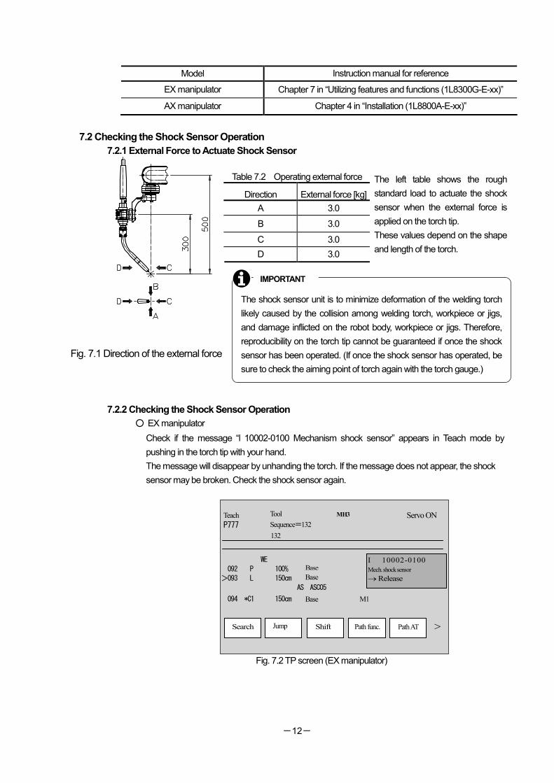
7.2 Checking the Shock Sensor Operation
7.2.1 External Force to Actuate Shock Sensor
Table 7.2 Operating external force
Direction External force [kg]
A 3.0
B 3.0
C 3.0
D 3.0
The left table shows the rough
standard load to actuate the shock
sensor when the external force is
applied on the torch tip.
These values depend on the shape
and length of the torch.
Fig. 7.1 Direction of the external force
7.2.2 Checking the Shock Sensor Operation
○ EX manipulator
Check if the message “l 10002-0100 Mechanism shock sensor” appears in Teach mode by
pushing in the torch tip with your hand.
The message will disappear by unhanding the torch. If the message does not appear, the shock
sensor may be broken. Check the shock sensor again.
Fig. 7.2 TP screen (EX manipulator)
Servo ON
> Path AT Path func. Shift Jump Search
Teach
P777
Tool
Sequence=132
MH3
I 10002-0100
Mech. shock sensor
→ Release
WE
092 P 100% 機械 >093 L 150cm 機械
AS ASC05
094 *C1 150cm 機械 M1
The shock sensor unit is to minimize deformation of the welding torch
likely caused by the collision among welding torch, workpiece or jigs,
and damage inflicted on the robot body, workpiece or jigs. Therefore,
reproducibility on the torch tip cannot be guaranteed if once the shock
sensor has been operated. (If once the shock sensor has operated, be
sure to check the aiming point of torch again with the torch gauge.)
IMPORTANT
132
Base
Base
Base
-13-
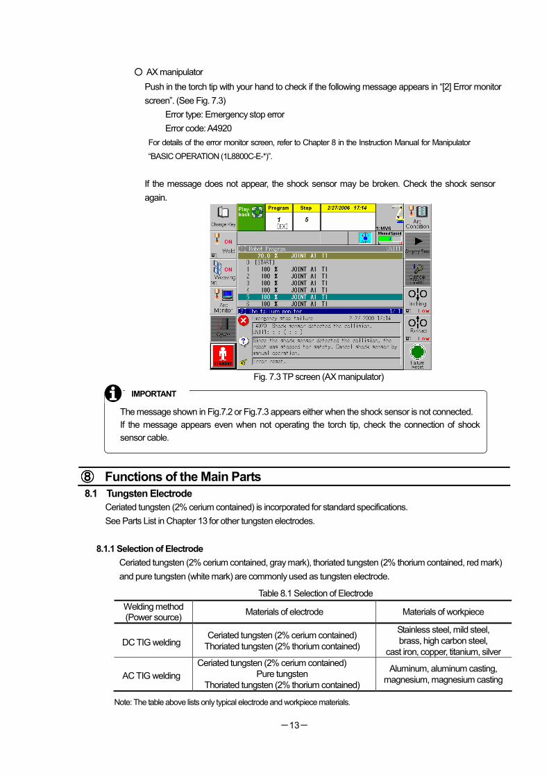
○ AX manipulator
Push in the torch tip with your hand to check if the following message appears in “[2] Error monitor
screen”. (See Fig. 7.3)
Error type: Emergency stop error
Error code: A4920
For details of the error monitor screen, refer to Chapter 8 in the Instruction Manual for Manipulator
“BASIC OPERATION (1L8800C-E-*)”.
If the message does not appear, the shock sensor may be broken. Check the shock sensor
again.
Fig. 7.3 TP screen (AX manipulator)
⑧⑧⑧⑧ Functions of the Main Parts
8.1 Tungsten Electrode Ceriated tungsten (2% cerium contained) is incorporated for standard specifications.
See Parts List in Chapter 13 for other tungsten electrodes.
8.1.1 Selection of Electrode
Ceriated tungsten (2% cerium contained, gray mark), thoriated tungsten (2% thorium contained, red mark)
and pure tungsten (white mark) are commonly used as tungsten electrode.
Table 8.1 Selection of Electrode
Welding method (Power source)
Materials of electrode Materials of workpiece
DC TIG welding Ceriated tungsten (2% cerium contained)
Thoriated tungsten (2% thorium contained)
Stainless steel, mild steel,
brass, high carbon steel,
cast iron, copper, titanium, silver
AC TIG welding
Ceriated tungsten (2% cerium contained)
Pure tungsten
Thoriated tungsten (2% thorium contained)
Aluminum, aluminum casting,
magnesium, magnesium casting
Note: The table above lists only typical electrode and workpiece materials.
The message shown in Fig.7.2 or Fig.7.3 appears either when the shock sensor is not connected.
If the message appears even when not operating the torch tip, check the connection of shock
sensor cable.
IMPORTANT
-14-
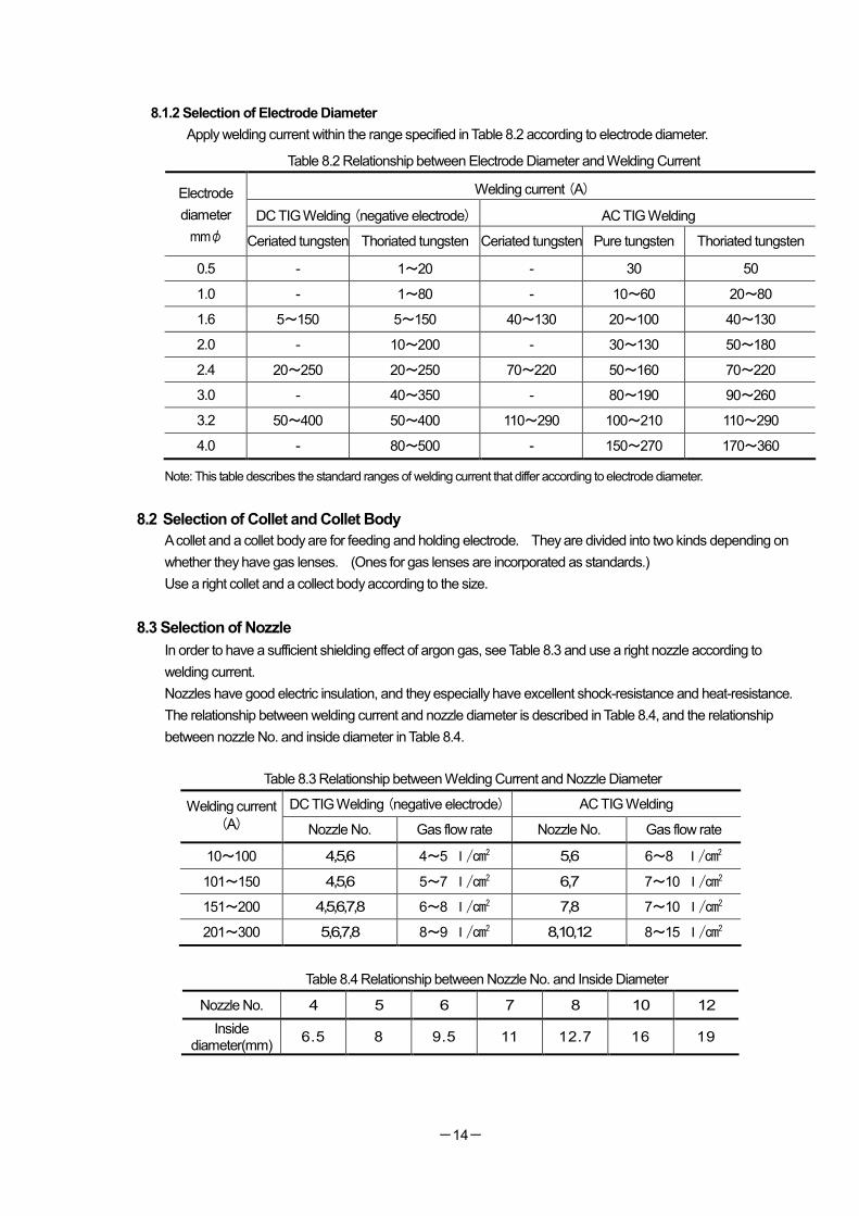
8.1.2 Selection of Electrode Diameter
Apply welding current within the range specified in Table 8.2 according to electrode diameter.
Table 8.2 Relationship between Electrode Diameter and Welding Current
Welding current (A)
DC TIG Welding (negative electrode) AC TIG Welding
Electrode
diameter
mmφ Ceriated tungsten Thoriated tungsten Ceriated tungsten Pure tungsten Thoriated tungsten
0.5 - 1~20 - 30 50
1.0 - 1~80 - 10~60 20~80
1.6 5~150 5~150 40~130 20~100 40~130
2.0 - 10~200 - 30~130 50~180
2.4 20~250 20~250 70~220 50~160 70~220
3.0 - 40~350 - 80~190 90~260
3.2 50~400 50~400 110~290 100~210 110~290
4.0 - 80~500 - 150~270 170~360
Note: This table describes the standard ranges of welding current that differ according to electrode diameter.
8.2 Selection of Collet and Collet Body
A collet and a collet body are for feeding and holding electrode. They are divided into two kinds depending on
whether they have gas lenses. (Ones for gas lenses are incorporated as standards.)
Use a right collet and a collect body according to the size.
8.3 Selection of Nozzle
In order to have a sufficient shielding effect of argon gas, see Table 8.3 and use a right nozzle according to
welding current.
Nozzles have good electric insulation, and they especially have excellent shock-resistance and heat-resistance.
The relationship between welding current and nozzle diameter is described in Table 8.4, and the relationship
between nozzle No. and inside diameter in Table 8.4.
Table 8.3 Relationship between Welding Current and Nozzle Diameter
DC TIG Welding (negative electrode) AC TIG Welding Welding current
(A) Nozzle No. Gas flow rate Nozzle No. Gas flow rate
10~100 4,5,6 4~5 l/cm2 5,6 6~8 l/cm2
101~150 4,5,6 5~7 l/cm2 6,7 7~10 l/cm2
151~200 4,5,6,7,8 6~8 l/cm2 7,8 7~10 l/cm2
201~300 5,6,7,8 8~9 l/cm2 8,10,12 8~15 l/cm2
Table 8.4 Relationship between Nozzle No. and Inside Diameter
Nozzle No. 4 5 6 7 8 10 12
Inside diameter(mm)
6.5 8 9.5 11 12.7 16 19
-15-
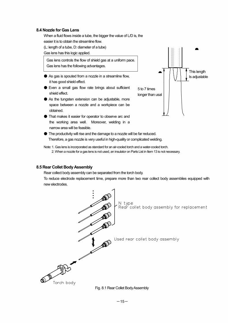
8.4 Nozzle for Gas Lens
When a fluid flows inside a tube, the bigger the value of L/D is, the
easier it is to obtain the streamline flow.
(L: length of a tube, D: diameter of a tube)
Gas lens has this logic applied.
● As gas is spouted from a nozzle in a streamline flow,
it has good shield effect.
● Even a small gas flow rate brings about sufficient
shield effect.
● As the tungsten extension can be adjustable, more
space between a nozzle and a workpiece can be
obtained.
● That makes it easier for operator to observe arc and
the working area well. Moreover, welding in a
narrow area will be feasible.
● The productivity will rise and the damage to a nozzle will be far reduced.
Therefore, a gas nozzle is very useful in high-quality or complicated welding.
Note: 1. Gas lens is incorporated as standard for an air-cooled torch and a water-cooled torch.
2. When a nozzle for a gas lens is not used, an insulator on Parts List in Item 13 is not necessary.
8.5 Rear Collet Body Assembly
Rear collect body assembly can be separated from the torch body.
To reduce electrode replacement time, prepare more than two rear collect body assemblies equipped with
new electrodes.
Fig. 8.1 Rear Collet Body Assembly
Gas lens controls the flow of shield gas at a uniform pace.
Gas lens has the following advantages.
●普通の5~7倍
●突き出し長さを大きくできます。
5 to 7 times
longer than usal
This length
Is adjustable
-16-
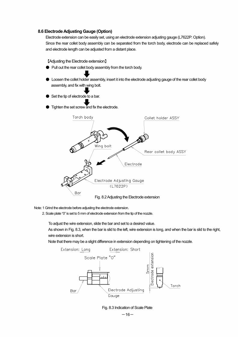
8.6 Electrode Adjusting Gauge (Option)
Electrode extension can be easily set, using an electrode extension adjusting gauge (L7622P: Option).
Since the rear collet body assembly can be separated from the torch body, electrode can be replaced safely
and electrode length can be adjusted from a distant place.
【Adjusting the Electrode extension】
● Pull out the rear collet body assembly from the torch body.
● Loosen the collet holder assembly, insert it into the electrode adjusting gauge of the rear collet body
assembly, and fix with wing bolt.
● Set the tip of electrode to a bar.
● Tighten the set screw and fix the electrode.
Fig. 8.2 Adjusting the Electrode extension
Note: 1 Grind the electrode before adjusting the electrode extension.
2. Scale plate “0” is set to 5 mm of electrode extension from the tip of the nozzle.
To adjust the wire extension, slide the bar and set to a desired value.
As shown in Fig. 8.3, when the bar is slid to the left, wire extension is long, and when the bar is slid to the right,
wire extension is short.
Note that there may be a slight difference in extension depending on tightening of the nozzle.
Fig. 8.3 Indication of Scale Plate
-17-
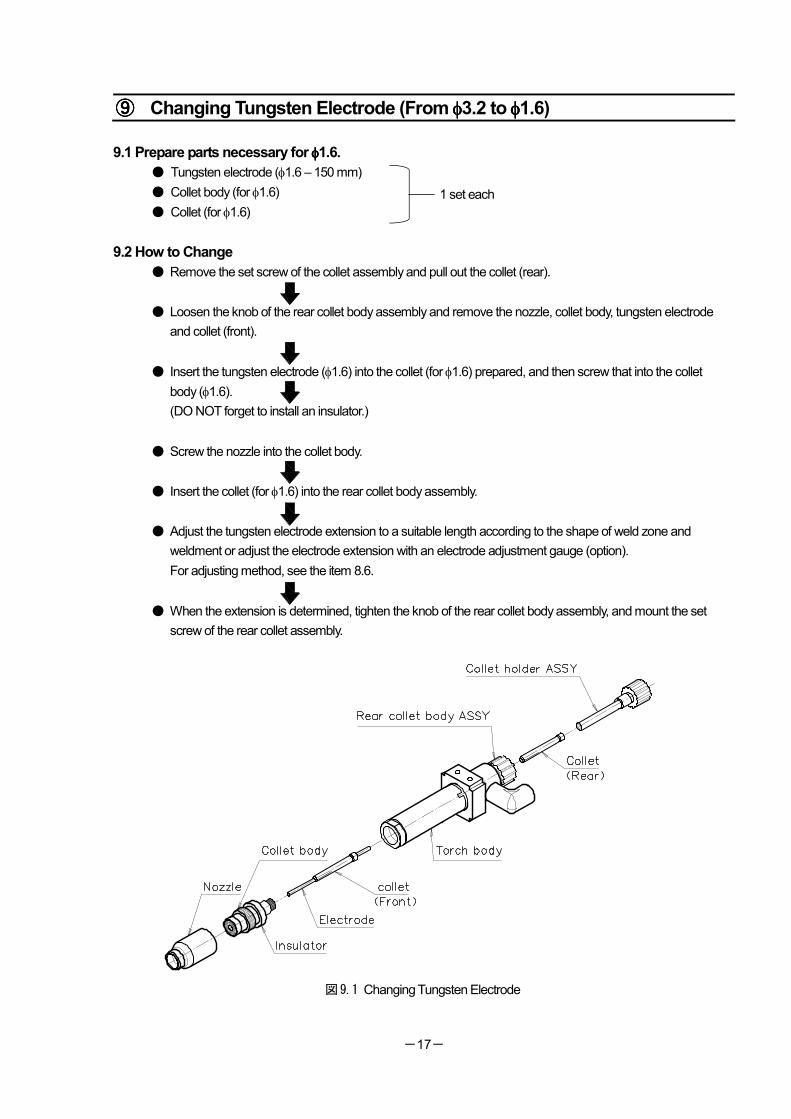
⑨⑨⑨⑨ Changing Tungsten Electrode (From φφφφ3.2 to φφφφ1.6)
9.1 Prepare parts necessary for φφφφ1.6.
● Tungsten electrode (φ1.6 – 150 mm)
● Collet body (for φ1.6)
● Collet (for φ1.6)
9.2 How to Change
● Remove the set screw of the collet assembly and pull out the collet (rear).
● Loosen the knob of the rear collet body assembly and remove the nozzle, collet body, tungsten electrode
and collet (front).
● Insert the tungsten electrode (φ1.6) into the collet (for φ1.6) prepared, and then screw that into the collet
body (φ1.6).
(DO NOT forget to install an insulator.)
● Screw the nozzle into the collet body.
● Insert the collet (for φ1.6) into the rear collet body assembly.
● Adjust the tungsten electrode extension to a suitable length according to the shape of weld zone and
weldment or adjust the electrode extension with an electrode adjustment gauge (option).
For adjusting method, see the item 8.6.
● When the extension is determined, tighten the knob of the rear collet body assembly, and mount the set
screw of the rear collet assembly.
図9.1 Changing Tungsten Electrode
1 set each
-18-
⑩⑩⑩⑩ Connection to Welding Power Supply
CAUTION
● Make sure to tighten the collet body and torch body firmly. If either of them is loose even slightly, the collet may be burned and seized or the operator may get burn due to heat-up.
● Refer to the instruction manual for each welding power source, and connect the torch properly.
⑪⑪⑪⑪ Requirements 11.1 When mounting this torch on the robot, connect the lead wire of the power cable to the connection part of
the workpiece-side welding cable of the electrode.
11.2 If there is any loosened part in any connection of the torch, heat generation and leakage of water, gas or air
may result. Make sure to tighten the connections securely.
11.3 Keep the gas flow rate at 7~8 l /min. for AC and 5~6 l /min. for DC for normal operations. When a gas lens
is in used, sufficient shield effect will be obtained at a lower rate. When it is windy, or the workpiece and the
torch need to be moved farther away from each other, raise the flow rate as required.
11.4 Keep the flow rate of the coolant at more than 1.2 l /min.
Appropriate water pressure is 0.1 (1kg/cm2) ~ 0.3 (3kg/cm
2) MPa.
DO NOT use the coolant at the pressure of more than 0.3 MPa (3kg/cm2).
Lower than 25°C is desirable for the temperature at the inlet.
11.5 Although the cable hose, gas hose, and coolant hose are all protected by hose sheaths, DO NOT put any
heavy piece on top of these cables, cause them to contact hot parts of the weldment, nor to be bent by
force.
11.6 Always keep the tungsten electrode clean.
1) When spatters stick to the electrode, generate arc on other steel plate, and it will be cleaned.
2) When granular structure is formed on the tip of the electrode, sharpen the tip by a grinder and so on to
form acute angles.
3) When the electrode sticks into the molten pool, turn OFF the power, take out the electrode and break it
at the lowermost part of the electrode. Then, finish the tip of the electrode with a grinder and so on.
11.7 Keep the nozzle clean as well. Remove its cap occasionally and check for any abnormal conditions.
11.8 Even when any external abnormal conditions cannot be observed, periodic inspection on worn parts is
desirable for maintenance of the torch and obtaining fine results of welding.
11.9 The shock sensor unit is to minimize deformation of the welding torch likely caused by the collision among
welding torch, workpiece or jigs, and damage inflicted on the robot body, workpiece or jigs. Therefore,
reproducibility on the torch tip cannot be guaranteed if once the shock sensor has been operated. (If once
the shock sensor has worked, check the aiming point of torch again with the torch gauge.)
-19-
Maintenance
⑫⑫⑫⑫ What if the Following Occur
Trouble Possible causes
1. The connections of welding cable of the torch and workpiece are incomplete.
2. The fuse of the control unit has blown.
3. Electromagnetic contactor does not work.
4. Argon gas has not flowed.
No arc generated
5. High frequency has not been generated.
1. The length of an arc is too short. Electrode damaged
2. The flow rate of argon gas is not enough.
1. The welding current is too large in proportion to the diameter of electrode. Electrode melted
2. The polarity of electrode is wrong.
1. Coolant has not flowed enough. Torch body overheated
2. The tightened parts became loose.
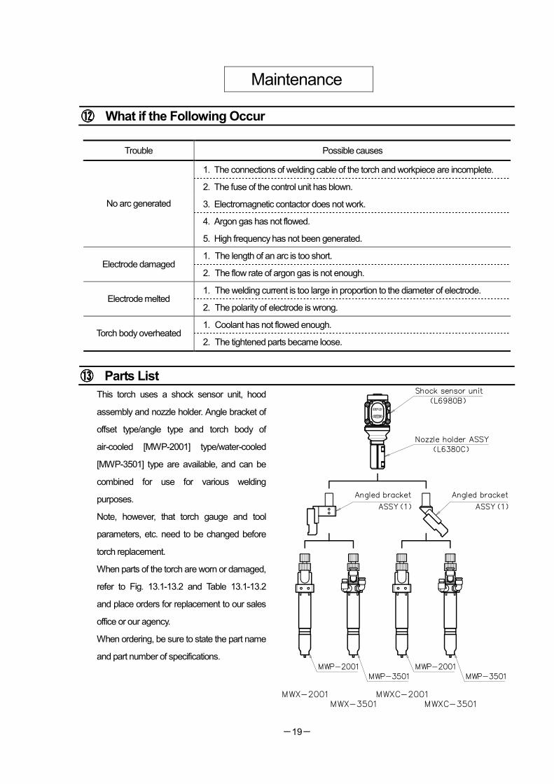
⑬⑬⑬⑬ Parts List
This torch uses a shock sensor unit, hood
assembly and nozzle holder. Angle bracket of
offset type/angle type and torch body of
air-cooled [MWP-2001] type/water-cooled
[MWP-3501] type are available, and can be
combined for use for various welding
purposes.
Note, however, that torch gauge and tool
parameters, etc. need to be changed before
torch replacement.
When parts of the torch are worn or damaged,
refer to Fig. 13.1-13.2 and Table 13.1-13.2
and place orders for replacement to our sales
office or our agency.
When ordering, be sure to state the part name
and part number of specifications.
-20-
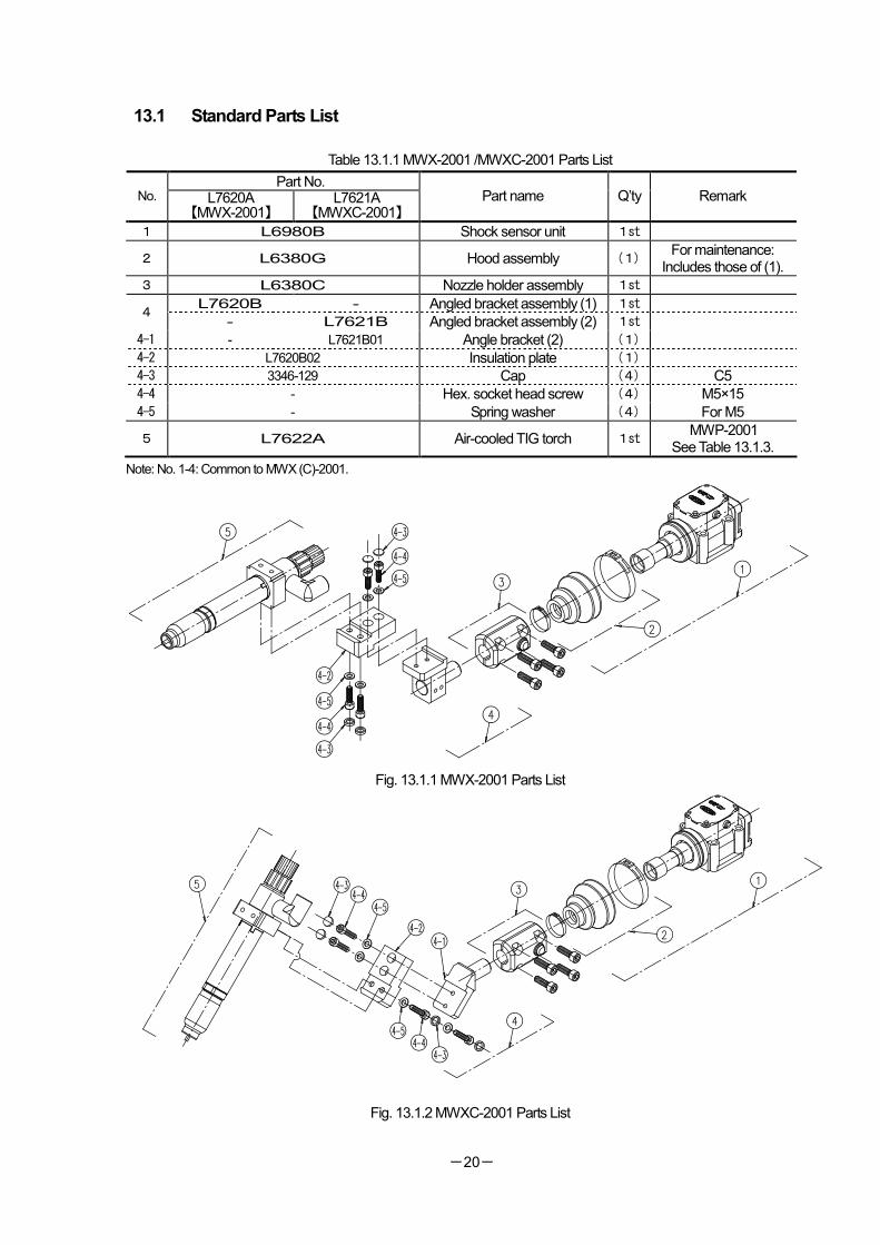
13.1 Standard Parts List
Table 13.1.1 MWX-2001 /MWXC-2001 Parts List
Part No. No. L7620A
【MWX-2001】 L7621A
【MWXC-2001】 Part name Q’ty Remark
1 L6980B Shock sensor unit 1st
2 L6380G Hood assembly (1) For maintenance:
Includes those of (1).
3 L6380C Nozzle holder assembly 1st
L7620B - Angled bracket assembly (1) 1st 4
- L7621B Angled bracket assembly (2) 1st
4-1 - L7621B01 Angle bracket (2) (1)
4-2 L7620B02 Insulation plate (1) 4-3 3346-129 Cap (4) C5
4-4 - Hex. socket head screw (4) M5×15
4-5 - Spring washer (4) For M5
5 L7622A Air-cooled TIG torch 1st MWP-2001
See Table 13.1.3.
Note: No. 1-4: Common to MWX (C)-2001.
Fig. 13.1.1 MWX-2001 Parts List
Fig. 13.1.2 MWXC-2001 Parts List
-21-
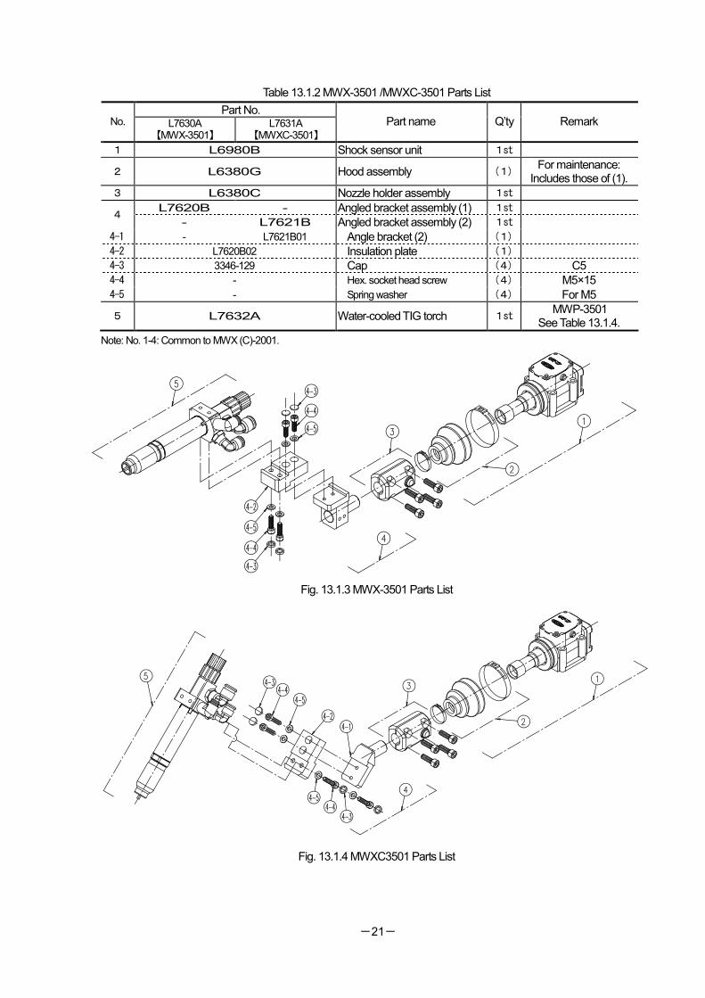
Table 13.1.2 MWX-3501 /MWXC-3501 Parts List
Part No. No. L7630A
【MWX-3501】 L7631A
【MWXC-3501】 Part name Q’ty Remark
1 L6980B Shock sensor unit 1st
2 L6380G Hood assembly (1) For maintenance:
Includes those of (1).
3 L6380C Nozzle holder assembly 1st
L7620B - Angled bracket assembly (1) 1st 4
- L7621B Angled bracket assembly (2) 1st
4-1 - L7621B01 Angle bracket (2) (1)
4-2 L7620B02 Insulation plate (1) 4-3 3346-129 Cap (4) C5
4-4 - Hex. socket head screw (4) M5×15
4-5 - Spring washer (4) For M5
5 L7632A Water-cooled TIG torch 1st MWP-3501
See Table 13.1.4.
Note: No. 1-4: Common to MWX (C)-2001.
Fig. 13.1.3 MWX-3501 Parts List
Fig. 13.1.4 MWXC3501 Parts List
-22-
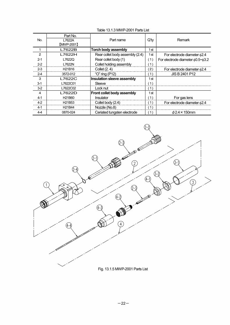
Table 13.1.3 MWP-2001 Parts List
Part No. No. L7622A
【MWP-2001】
Part name Q’ty Remark
1 L7622B Torch body assembly 1st
2 L7622H Rear collet body assembly (2.4) 1st For electrode diameter φ2.4
2-1 L7622Q Rear collet body (1) (1) For electrode diameter φ0.5~φ3.2
2-2 L7622N Collet holding assembly (1)
2-3 H21B16 Collet (2. 4) (2) For electrode diameter φ2.4
2-4 3572-012 “O” ring (P12) (1) JIS B 2401 P12
3 L7622C Insulation sleeve assembly 1st
3-1 L7622C01 Sleeve (1)
3-2 L7622C02 Lock nut (1)
4 L7622D Front collet body assembly 1st
4-1 H21B60 Insulator (1) For gas lens
4-2 H21B53 Collet body (2.4) (1) For electrode diameter φ2.4 4-1 H21B44 Nozzle (No.8) (1)
4-4 0870-024 Ceriated tungsten electrode (1) φ2.4×150mm
Fig. 13.1.5 MWP-2001 Parts List
-23-
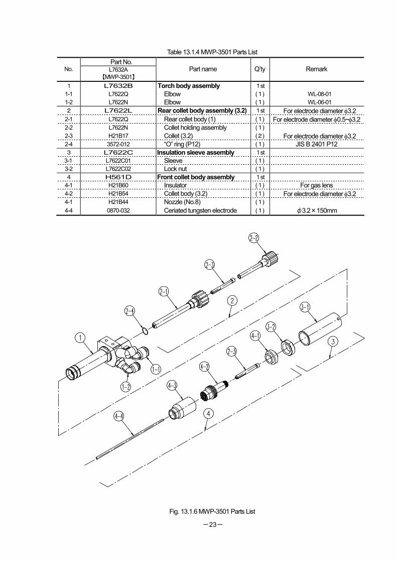
Table 13.1.4 MWP-3501 Parts List
Part No. No. L7632A
【MWP-3501】
Part name Q’ty Remark
1 L7632B Torch body assembly 1st
1-1 L7622Q Elbow (1) WL-08-01
1-2 L7622N Elbow (1) WL-06-01
2 L7622L Rear collet body assembly (3.2) 1st For electrode diameter φ3.2
2-1 L7622Q Rear collet body (1) (1) For electrode diameter φ0.5~φ3.2 2-2 L7622N Collet holding assembly (1)
2-3 H21B17 Collet (3.2) (2) For electrode diameter φ3.2 2-4 3572-012 “O” ring (P12) (1) JIS B 2401 P12
3 L7622C Insulation sleeve assembly 1st
3-1 L7622C01 Sleeve (1)
3-2 L7622C02 Lock nut (1)
4 H561D Front collet body assembly 1st
4-1 H21B60 Insulator (1) For gas lens
4-2 H21B54 Collet body (3.2) (1) For electrode diameter φ3.2 4-1 H21B44 Nozzle (No.8) (1)
4-4 0870-032 Ceriated tungsten electrode (1) φ3.2×150mm
Fig. 13.1.6 MWP-3501 Parts List
-24-
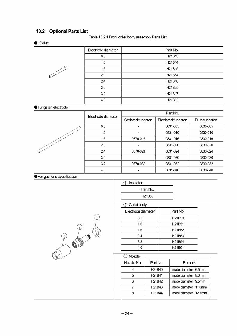
13.2 Optional Parts List Table 13.2.1 Front collet body assembly Parts List
● Collet
Electrode diameter Part No.
0.5 H21B13
1.0 H21B14
1.6 H21B15
2.0 H21B64
2.4 H21B16
3.0 H21B65
3.2 H21B17
4.0 H21B63
●Tungsten electrode
Part No. Electrode diameter
Ceriated tungsten Thoriated tungsten Pure tungsten
0.5 - 0831-005 0830-005
1.0 - 0831-010 0830-010
1.6 0870-016 0831-016 0830-016
2.0 - 0831-020 0830-020
2.4 0870-024 0831-024 0830-024
3.0 - 0831-030 0830-030
3.2 0870-032 0831-032 0830-032
4.0 - 0831-040 0830-040
●For gas lens specification
① Insulator
Part No.
H21B60
② Collet body
Electrode diameter Part No.
0.5 H21B50
1.0 H21B51
1.6 H21B52
2.4 H21B53
3.2 H21B54
4.0 H21B61
③ Nozzle
Nozzle No. Part No. Remark
4 H21B40 Inside diameter : 6.5mm
5 H21B41 Inside diameter : 8.0mm
6 H21B42 Inside diameter : 9.5mm
7 H21B43 Inside diameter : 11.0mm
8 H21B44 Inside diameter : 12.7mm
-25-
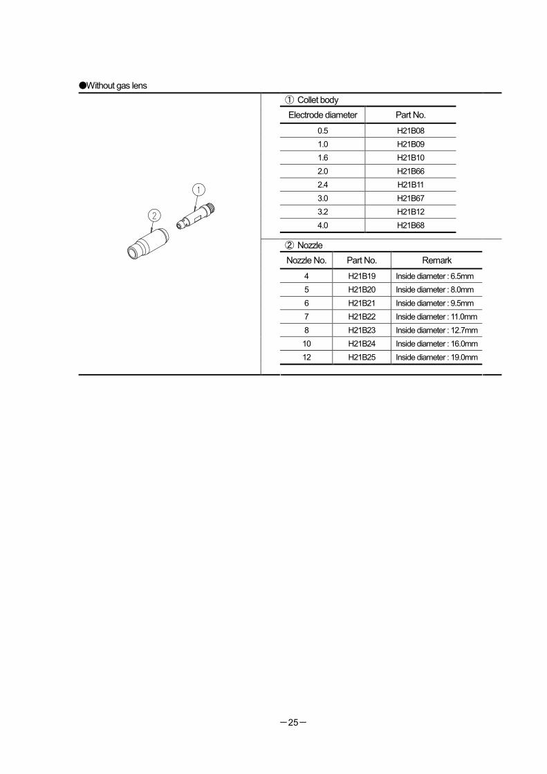
●Without gas lens
① Collet body
Electrode diameter Part No.
0.5 H21B08
1.0 H21B09
1.6 H21B10
2.0 H21B66
2.4 H21B11
3.0 H21B67
3.2 H21B12
4.0 H21B68
② Nozzle
Nozzle No. Part No. Remark
4 H21B19 Inside diameter : 6.5mm
5 H21B20 Inside diameter : 8.0mm
6 H21B21 Inside diameter : 9.5mm
7 H21B22 Inside diameter : 11.0mm
8 H21B23 Inside diameter : 12.7mm
10 H21B24 Inside diameter : 16.0mm
12 H21B25 Inside diameter : 19.0mm
-26-
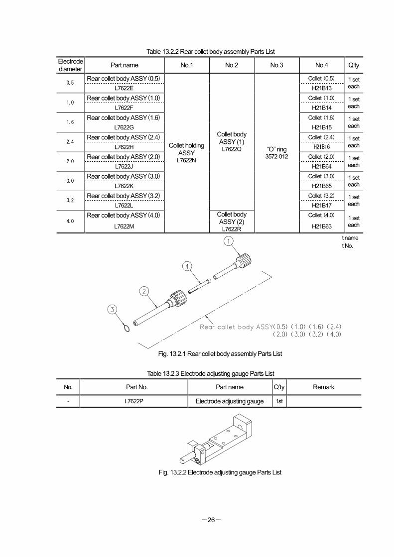
Table 13.2.2 Rear collet body assembly Parts List
Electrode diameter
Part name No.1 No.2 No.3 No.4 Q’ty
Rear collet body ASSY(0.5) Collet (0.5) 0.5
L7622E H21B13
1 set each
Rear collet body ASSY(1.0) Collet (1.0) 1.0
L7622F H21B14
1 set each
Rear collet body ASSY(1.6) Collet (1.6) 1.6
L7622G H21B15
1 set each
Rear collet body ASSY(2.4) Collet (2.4) 2.4
L7622H H21B16
1 set each
Rear collet body ASSY(2.0) Collet (2.0) 2.0
L7622J H21B64
1 set each
Rear collet body ASSY(3.0) Collet (3.0) 3.0
L7622K H21B65
1 set each
Rear collet body ASSY(3.2) Collet (3.2) 3.2
L7622L
Collet body ASSY (1) L7622Q
H21B17
1 set each
Rear collet body ASSY(4.0) Collet (4.0) 4.0
L7622M
Collet holding ASSY L7622N
Collet body ASSY (2) L7622R
“O” ring 3572-012
H21B63
1 set each
Upper row: Part name
Lower row: Part No.
Fig. 13.2.1 Rear collet body assembly Parts List
Table 13.2.3 Electrode adjusting gauge Parts List
No. Part No. Part name Q’ty Remark
- L7622P Electrode adjusting gauge 1st
Fig. 13.2.2 Electrode adjusting gauge Parts List
-27-
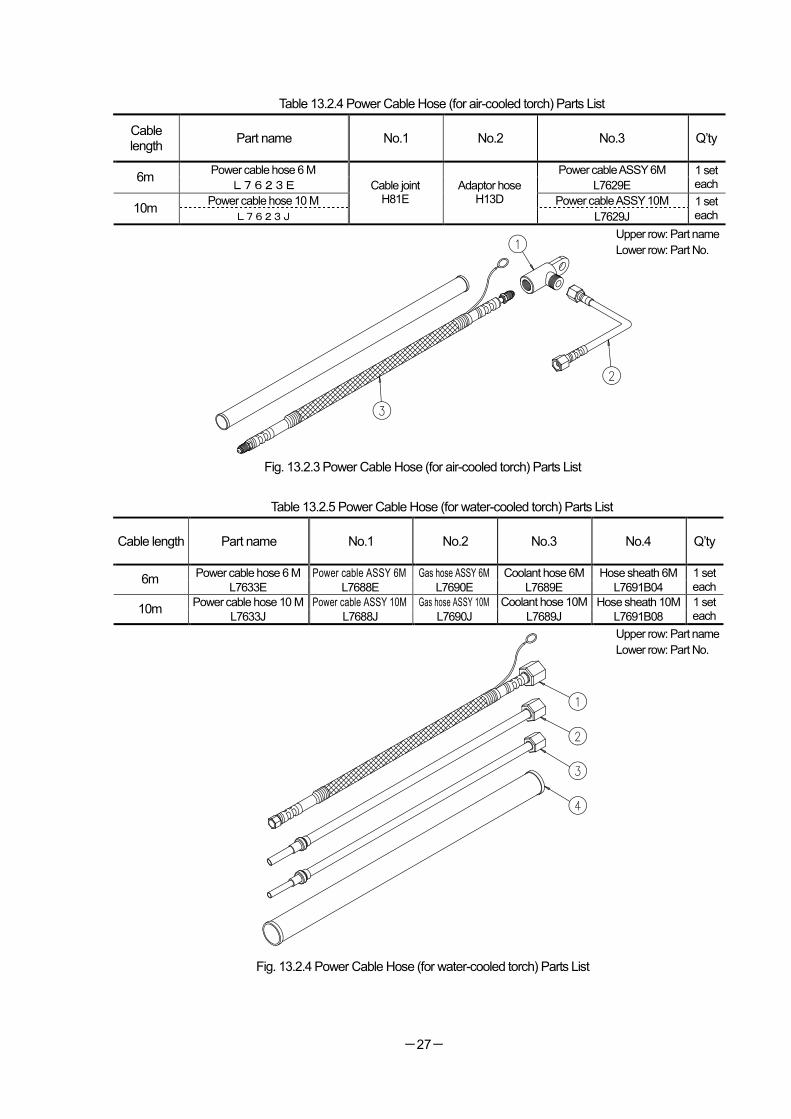
Table 13.2.4 Power Cable Hose (for air-cooled torch) Parts List
Cable length
Part name No.1 No.2 No.3 Q’ty
Power cable hose 6 M Power cable ASSY 6M 6m
L7623E L7629E
1 set each
Power cable hose 10 M Power cable ASSY 10M 10m
L7623J
Cable joint H81E
Adaptor hose H13D
L7629J
1 set each
Upper row: Part name
Lower row: Part No.
Fig. 13.2.3 Power Cable Hose (for air-cooled torch) Parts List
Table 13.2.5 Power Cable Hose (for water-cooled torch) Parts List
Cable length Part name No.1 No.2 No.3 No.4 Q’ty
Power cable hose 6 M Power cable ASSY 6M Gas hose ASSY 6M Coolant hose 6M Hose sheath 6M 6m
L7633E L7688E L7690E L7689E L7691B04
1 set each
Power cable hose 10 M Power cable ASSY 10M Gas hose ASSY 10M Coolant hose 10M Hose sheath 10M 10m
L7633J L7688J L7690J L7689J L7691B08
1 set each
Upper row: Part name
Lower row: Part No.
Fig. 13.2.4 Power Cable Hose (for water-cooled torch) Parts List
-28-
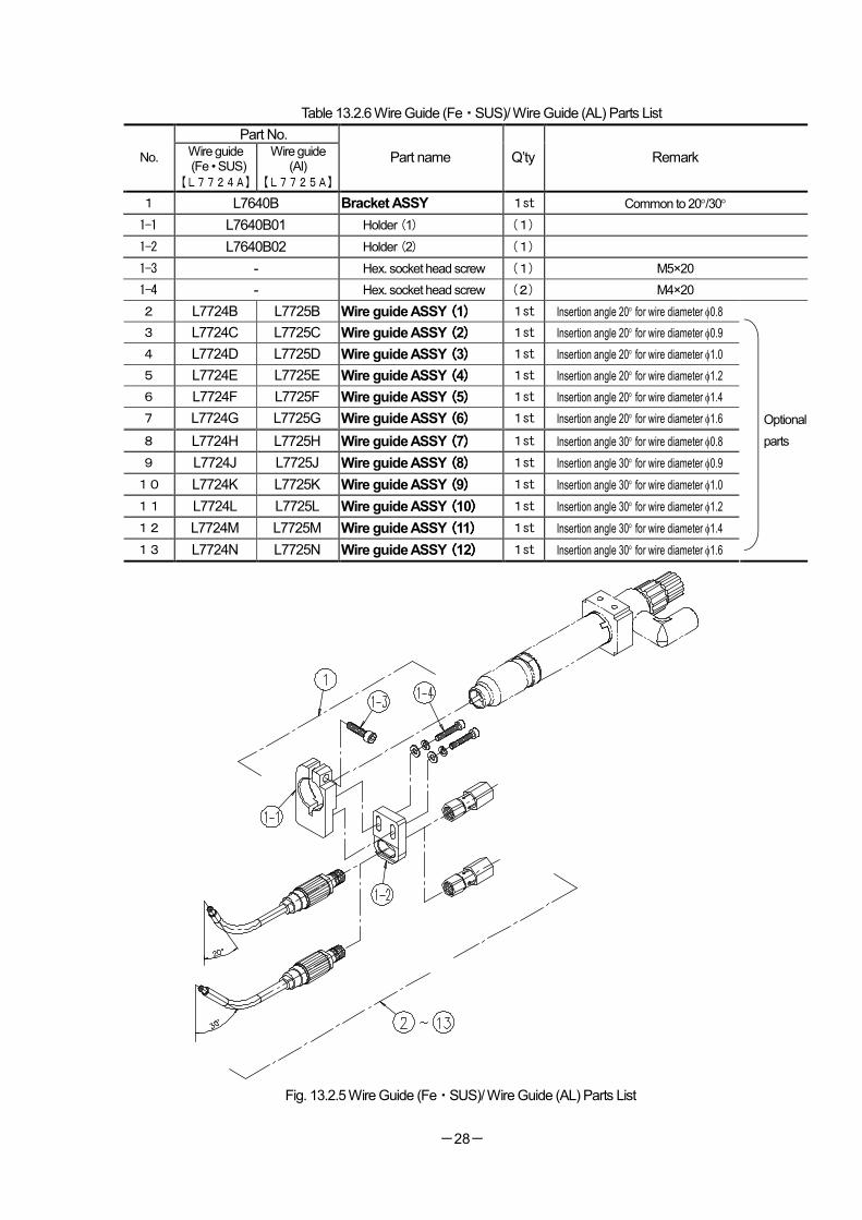
Table 13.2.6 Wire Guide (Fe・SUS)/ Wire Guide (AL) Parts List
Part No.
No. Wire guide (Fe • SUS)
【L7724A】
Wire guide (Al)
【L7725A】
Part name Q’ty Remark
1 L7640B Bracket ASSY 1st Common to 20°/30°
1-1 L7640B01 Holder (1) (1)
1-2 L7640B02 Holder (2) (1)
1-3 - Hex. socket head screw (1) M5×20
1-4 - Hex. socket head screw (2) M4×20
2 L7724B L7725B Wire guide ASSY ((((1)))) 1st Insertion angle 20° for wire diameter φ0.8
3 L7724C L7725C Wire guide ASSY ((((2)))) 1st Insertion angle 20° for wire diameter φ0.9
4 L7724D L7725D Wire guide ASSY ((((3)))) 1st Insertion angle 20° for wire diameter φ1.0
5 L7724E L7725E Wire guide ASSY ((((4)))) 1st Insertion angle 20° for wire diameter φ1.2
6 L7724F L7725F Wire guide ASSY ((((5)))) 1st Insertion angle 20° for wire diameter φ1.4
7 L7724G L7725G Wire guide ASSY ((((6)))) 1st Insertion angle 20° for wire diameter φ1.6
8 L7724H L7725H Wire guide ASSY ((((7)))) 1st Insertion angle 30° for wire diameter φ0.8
9 L7724J L7725J Wire guide ASSY ((((8)))) 1st Insertion angle 30° for wire diameter φ0.9
10 L7724K L7725K Wire guide ASSY ((((9)))) 1st Insertion angle 30° for wire diameter φ1.0
11 L7724L L7725L Wire guide ASSY ((((10)))) 1st Insertion angle 30° for wire diameter φ1.2
12 L7724M L7725M Wire guide ASSY ((((11)))) 1st Insertion angle 30° for wire diameter φ1.4
13 L7724N L7725N Wire guide ASSY ((((12)))) 1st Insertion angle 30° for wire diameter φ1.6
Fig. 13.2.5 Wire Guide (Fe・SUS)/ Wire Guide (AL) Parts List
Optional
parts
-29-
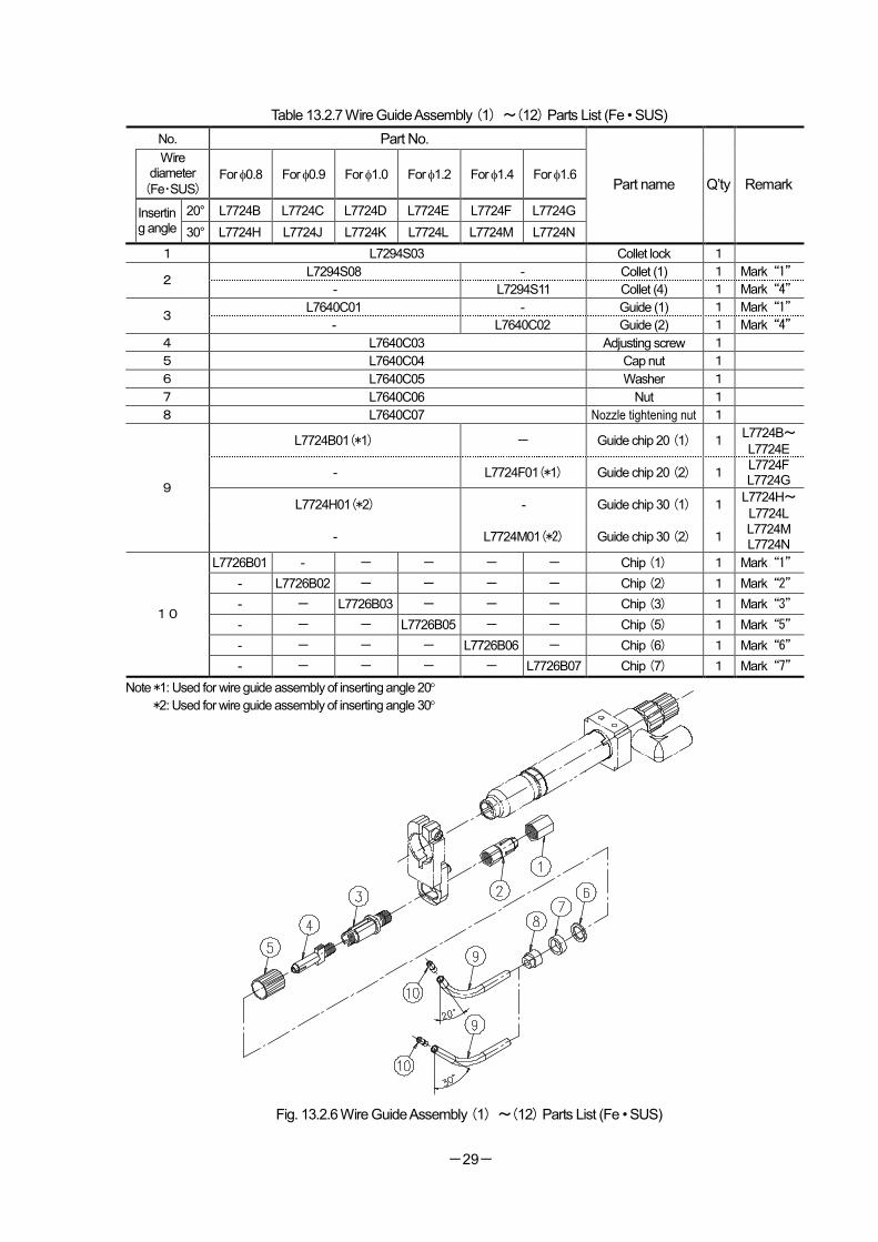
Table 13.2.7 Wire Guide Assembly (1) ~(12) Parts List (Fe • SUS)
No. Part No.
Wire diameter
(Fe・SUS) For φ0.8 For φ0.9 For φ1.0 For φ1.2 For φ1.4 For φ1.6
20° L7724B L7724C L7724D L7724E L7724F L7724G Inserting angle 30° L7724H L7724J L7724K L7724L L7724M L7724N
Part name Q’ty Remark
1 L7294S03 Collet lock 1
L7294S08 - Collet (1) 1 Mark“1” 2
- L7294S11 Collet (4) 1 Mark“4”
L7640C01 - Guide (1) 1 Mark“1” 3
- L7640C02 Guide (2) 1 Mark“4”
4 L7640C03 Adjusting screw 1
5 L7640C04 Cap nut 1
6 L7640C05 Washer 1
7 L7640C06 Nut 1
8 L7640C07 Nozzle tightening nut 1
L7724B01(*1) - Guide chip 20 (1) 1 L7724B~L7724E
- L7724F01(*1) Guide chip 20 (2) 1 L7724F L7724G
L7724H01(*2) - Guide chip 30 (1) 1 L7724H~L7724L
9
- L7724M01(*2) Guide chip 30 (2) 1 L7724M L7724N
L7726B01 - - - - - Chip (1) 1 Mark“1”
- L7726B02 - - - - Chip (2) 1 Mark“2”
- - L7726B03 - - - Chip (3) 1 Mark“3”
- - - L7726B05 - - Chip (5) 1 Mark“5”
- - - - L7726B06 - Chip (6) 1 Mark“6”
10
- - - - - L7726B07 Chip (7) 1 Mark“7”
Note *1: Used for wire guide assembly of inserting angle 20°
*2: Used for wire guide assembly of inserting angle 30°
Fig. 13.2.6 Wire Guide Assembly (1) ~(12) Parts List (Fe • SUS)
-30-
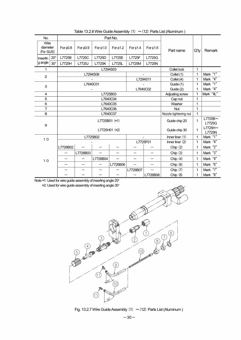
Table 13.2.8 Wire Guide Assembly (1) ~(12) Parts List (Aluminum )
No. Part No.
Wire diameter
(Fe・SUS) For φ0.8 For φ0.9 For φ1.0 For φ1.2 For φ1.4 For φ1.6
20° L7725B L7725C L7725D L7725E L7725F L7725G Inserting angle 30° L7725H L7725J L7725K L7725L L7725M L7725N
Part name Q’ty Remark
1 L7294S03 Collet lock 1
L7294S08 - Collet (1) 1 Mark“1” 2
- L7294S11 Collet (4) 1 Mark“4”
L7640C01 - Guide (1) 1 Mark“1” 3
- L7640C02 Guide (2) 1 Mark“4”
4 L7725B03 Adjusting screw 1 Mark“AL”
5 L7640C04 Cap nut 1
6 L7640C05 Washer 1
7 L7640C06 Nut 1
8 L7640C07 Nozzle tightening nut 1
L7725B01 (*1) Guide chip 20 1 L7725B~L7725G
9
L7725H01 (*2) Guide chip 30 1 L7725H~L7725N
L7725B02 - Inner liner (1) 1 Mark“1” 10
- L7725F01 Inner liner (2) 1 Mark“4”
L7726B02 - - - - - Chip (2) 1 Mark“2”
- L7726B03 - - - - Chip (3) 1 Mark“3”
- - L7726B04 - - - Chip (4) 1 Mark“4”
- - - L7726B06 - - Chip (6) 1 Mark“6”
- - - - L7726B07 - Chip (7) 1 Mark“7”
10
- - - - - L7726B08 Chip (8) 1 Mark“8”
Note *1: Used for wire guide assembly of inserting angle 20°
*2: Used for wire guide assembly of inserting angle 30°
Fig. 13.2.7 Wire Guide Assembly (1) ~(12) Parts List (Aluminum )
-31-
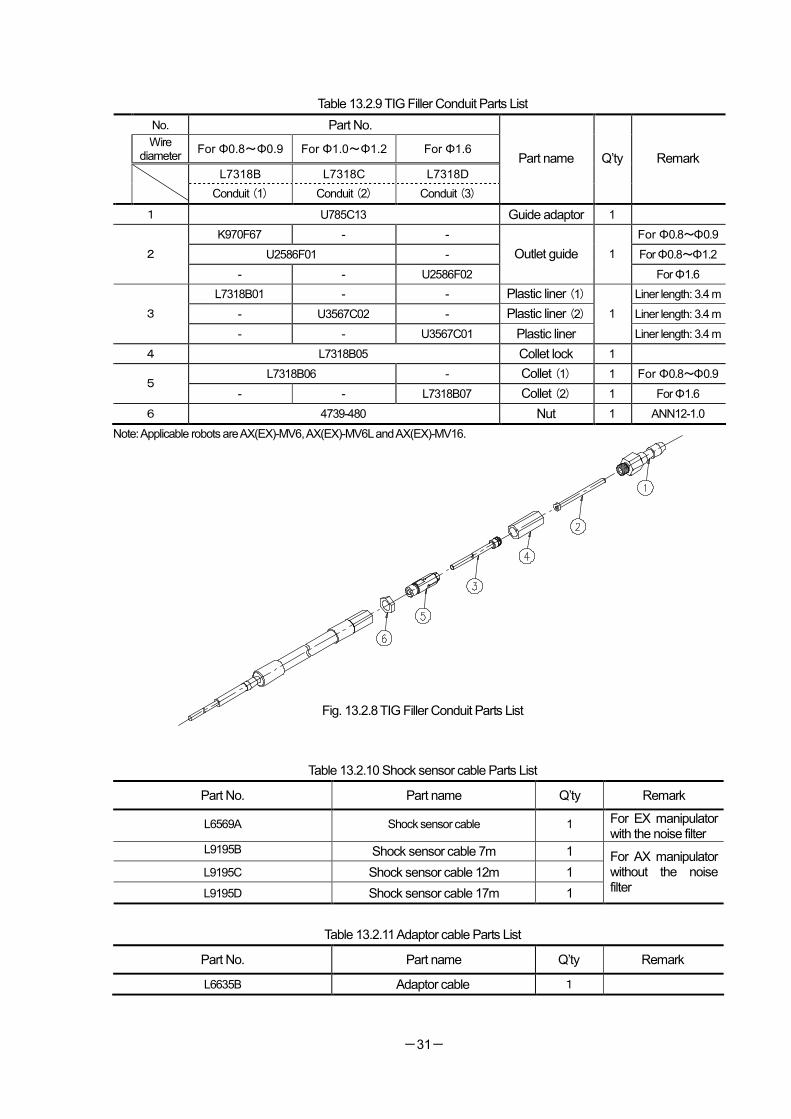
Table 13.2.9 TIG Filler Conduit Parts List
No. Part No.
Wire diameter
For Φ0.8~Φ0.9 For Φ1.0~Φ1.2 For Φ1.6
L7318B L7318C L7318D
Conduit (1) Conduit (2) Conduit (3)
Part name Q’ty Remark
1 U785C13 Guide adaptor 1
K970F67 - - For Φ0.8~Φ0.9
U2586F01 - For Φ0.8~Φ1.2 2
- - U2586F02
Outlet guide 1
For Φ1.6
L7318B01 - - Plastic liner (1) Liner length: 3.4 m
- U3567C02 - Plastic liner (2) Liner length: 3.4 m 3
- - U3567C01 Plastic liner
1
Liner length: 3.4 m
4 L7318B05 Collet lock 1
L7318B06 - Collet (1) 1 For Φ0.8~Φ0.9 5
- - L7318B07 Collet (2) 1 For Φ1.6
6 4739-480 Nut 1 ANN12-1.0
Note: Applicable robots are AX(EX)-MV6, AX(EX)-MV6L and AX(EX)-MV16.
Fig. 13.2.8 TIG Filler Conduit Parts List
Table 13.2.10 Shock sensor cable Parts List
Part No. Part name Q’ty Remark
L6569A Shock sensor cable 1 For EX manipulator with the noise filter
L9195B Shock sensor cable 7m 1
L9195C Shock sensor cable 12m 1
L9195D Shock sensor cable 17m 1
For AX manipulator without the noise filter
Table 13.2.11 Adaptor cable Parts List
Part No. Part name Q’ty Remark
L6635B Adaptor cable 1

Instruction Manual (TIG torch) MWX(C)-2001 / MWX(C)-3501 type
No.1L7620-E-1 February 2006 1st Edition