for Telecom Optical Networks - ist-brighter.eu · Raman Amplification for Telecom Optical Networks...
27
Raman Amplification for Telecom Optical Networks Dominique Bayart AlcatelLucent Bell Labs France, Research Center of Villarceaux Training day www.Brighter.eu project Cork, June 20th 2008
Transcript of for Telecom Optical Networks - ist-brighter.eu · Raman Amplification for Telecom Optical Networks...

Raman Amplification
for Telecom Optical Networks
Dominique Bayart AlcatelLucent Bell Labs France, Research Center of Villarceaux
Training day www.Brighter.eu project Cork, June 20th 2008
Raman Amplification for Telecom Optical Networks D. Bayart – Bell Labs France
Raman Amplification for Telecom Optical Networks
Outline of the talk
Raman interaction of Light with the glass Spectral and power characteristics Noise performance and limitations (Rayleigh, noise transfer) System implementation Lumped Raman amplifiers

Raman Amplification for Telecom Optical Networks D. Bayart – Bell Labs France
Effect happens for any pump frequency, polarization dependent Instantaneous effect (not the travel time of the pump along the fiber !) Peak Raman shift = 13 THz (glass phonon energy) Top width = 2.5 THz, can be broadened with multiλ pumping
Raman amplification : Principle
Long interaction fibers Confinement Attenuation at the pump wavelength is paramount
O
O
Si Pump
Signal
( = f pump 13 THz )
Vibrational excitation
Signal
Measured ga in curve : 1 pump @ 1487 nm
0
5
10
15
20
1500 1530 1560 1590 1620 nm
On/o
ff G
ain (dB)
DSF fiber
p p
L
eff
r dB OFF ON P e
A g G
p
⋅ −
⋅ ⋅ = ⋅ −
α
α 1 10 ln 10
/
ρ α 1
= eff L A eff is the Raman effective area of the fiber L eff : Effective length of the fiber expressed as :
Raman Amplification for Telecom Optical Networks D. Bayart – Bell Labs France
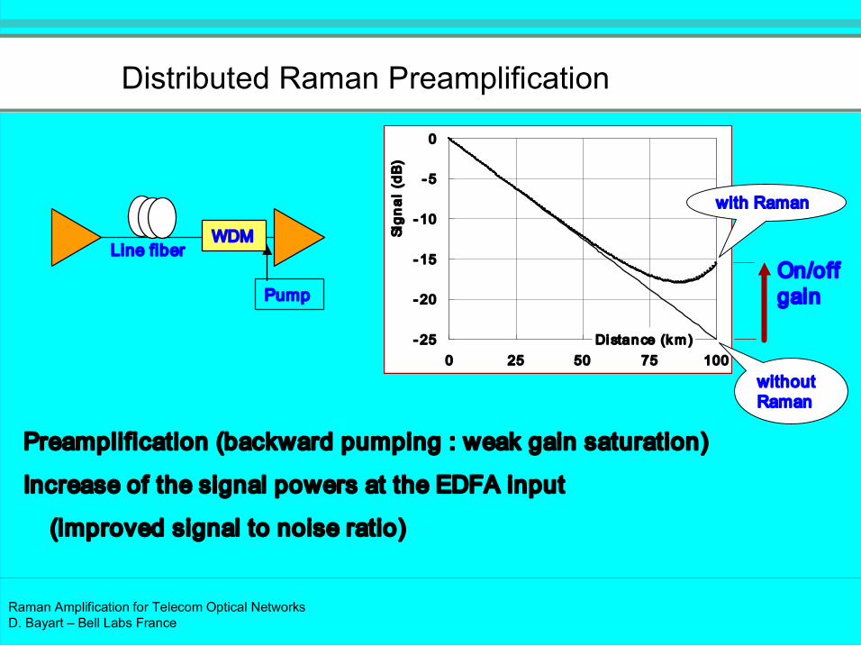
Distributed Raman Preamplification
Preamplification (backward pumping : weak gain saturation)
Increase of the signal powers at the EDFA input
(improved signal to noise ratio)
25
20
15
10
5
0
0 25 50 75 100 Distance (km)
Sign
al (dB
)
On/off gain
with Raman
without Raman
Pump
WDM Line fiber
Raman Amplification for Telecom Optical Networks D. Bayart – Bell Labs France
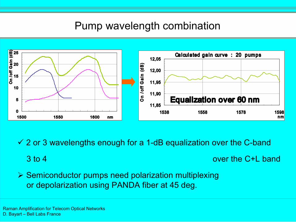
Ca lculated ga in curve : 20 pumps
11,85
11,90
11,95
12,00
12,05
1538 1558 1578 1598 nm
On /off Gain (dB
) ü 2 or 3 wavelengths enough for a 1dB equalization over the Cband
3 to 4 over the C+L band
Ø Semiconductor pumps need polarization multiplexing or depolarization using PANDA fiber at 45 deg.
0
5
10
15
20
25
1500 1550 1600 nm
On /off G
ain (dB)
Equalization over 60 nm
Pump wavelength combination

Raman Amplification for Telecom Optical Networks D. Bayart – Bell Labs France
Fiber efficiency per unit length and per W of pump
0
0,2
0,4
0,6
0,8
0 3 6 9 12 15 18
Ram
an efficiency C R (W
1 .km
1 )
Frequency Shift (THz)
NZDSF NZDSF+
SMF
TeraLight
PSCF
0.68 0.75
0.40 0.51
0.38 13.3THz peak (W 1 .km 1 )
1486nm pumping
C R = 0.23 G on/off / (P p .L eff_p ) C R Max
PSCF : Pure Silica Core Fiber
Raman Amplification for Telecom Optical Networks D. Bayart – Bell Labs France
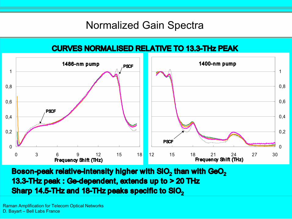
Normalized Gain Spectra
12 15 18 21 24 27 30 Frequency Sh i ft (THz)
0
0,2
0,4
0,6
0,8
1
0
0,2
0,4
0,6
0,8
1
0 3 6 9 12 15 18 Frequency Sh i ft (THz)
1486nm pump 1400nm pump
PSCF
PSCF
PSCF
Bosonpeak relativeintensity higher with SiO 2 than with GeO 2 13.3THz peak : Gedependent, extends up to > 20 THz Sharp 14.5THz and 18THz peaks specific to SiO 2
CURVES NORMALISED RELATIVE TO 13.3THz PEAK
Raman Amplification for Telecom Optical Networks D. Bayart – Bell Labs France
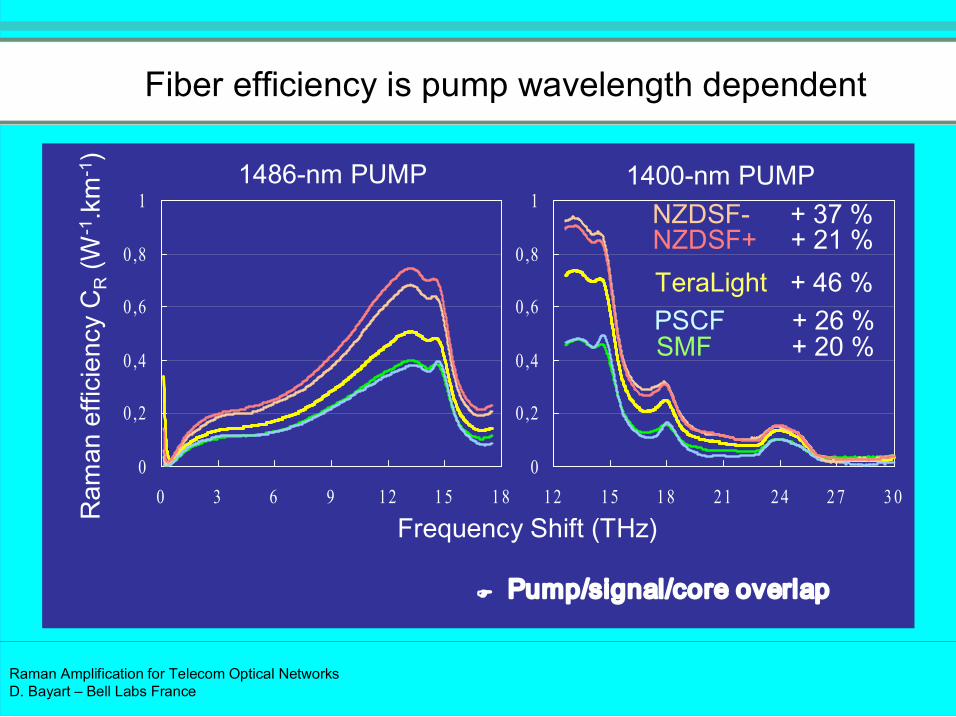
Fiber efficiency is pump wavelength dependent
0
0 ,2
0 ,4
0 ,6
0 ,8
1
12 15 1 8 21 24 2 7 3 0 0
0 ,2
0 ,4
0 ,6
0 ,8
1
0 3 6 9 12 1 5 1 8 Ram
an efficiency C R (W
1 .km
1 )
Frequency Shift (THz)
1486nm PUMP 1400nm PUMP NZDSF NZDSF+
SMF
TeraLight PSCF
+ 37 % + 21 %
+ 20 %
+ 46 % + 26 %
F Pump/signal/core overlap

Raman Amplification for Telecom Optical Networks D. Bayart – Bell Labs France
Effect of interchannel Raman depletion
Input fiber 10 dBm /channel (linear regime)
5.6 dBm /ch.
100 km #1
#32
Tx Rx
0.7 dB
2.3 dB

Raman Amplification for Telecom Optical Networks D. Bayart – Bell Labs France
Smallfrequencyshift energy transfers
1529 1561 1602
Frequency shift (THz)
Wavelength (nm)
27
22
17 Cband Lband
NZDSF NZDSF+
SMF TeraLight
PSCF
0
0 ,1
0 ,2
0 ,3
0 ,4
0 3 6 9 Ram
an efficiency (W
1 .km
1 )
1569
1486nm PUMP
Raman Amplification for Telecom Optical Networks D. Bayart – Bell Labs France
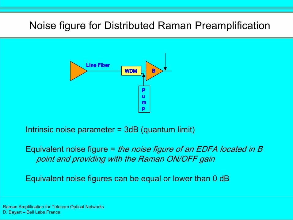
P u m p
WDM Line Fiber
Intrinsic noise parameter = 3dB (quantum limit)
Equivalent noise figure = the noise figure of an EDFA located in B point and providing with the Raman ON/OFF gain
Equivalent noise figures can be equal or lower than 0 dB
B
Noise figure for Distributed Raman Preamplification

Raman Amplification for Telecom Optical Networks D. Bayart – Bell Labs France
DoubleRayleigh Scattering
• Signal (neglecting the DRS term):
• Simple Rayleighscattered signal:
• Double Rayleighscattered signal: dy L y G y P r L P
dz z y G z P r y P
z G P z P
net L
RS DRS
L
y net S RS
net S S
). ( ). ( . ) (
). ( ). ( . ) (
) 0 ( ). 0 ( ) (
0 → =
→ =
→ =
∫
∫
⇒ DRS noisetosignal ratio at the end of the fibre: R DRS =
P DRS (L)/P S (L)
0 L
Ps (z) r.Ps(z )
P DRS (L)

Raman Amplification for Telecom Optical Networks D. Bayart – Bell Labs France
DoubleRayleigh Scattering (DRS)
• DRS is a delayed copy of the signal => beating noise at detection with the signal by quadratic detection:
• Exists in all transmissions but is more penalizing with distributed Raman amplification: DRS is amplified during its doublepath
• Crucial issue: DRS impairment is a limit to high amounts of Raman gain
• ASE and DRS essentially differ by their spectral distribution:
ASE is constant with wavelength in the range of the signal bandwidth
DRS is a replica of the signal optical spectrum
) ) ( ( 2 ) ( 2 2 ν
ν π ∆ +
∆ ≈
f R f RIN DRS

Raman Amplification for Telecom Optical Networks D. Bayart – Bell Labs France
Electrical measurement of DRS
155 150 145 140 135 130 125 120 115 110 105 100 95
0 1 2 3 4 5 6 7 8 9 10
Frequency (MHz)
RIN (d
B/Hz) .
24dB gain
16dB gain
10dB gain 8dB gain 6dB gain 4dB gain 2dB gain
source
0dB gain
Raman Amplification for Telecom Optical Networks D. Bayart – Bell Labs France
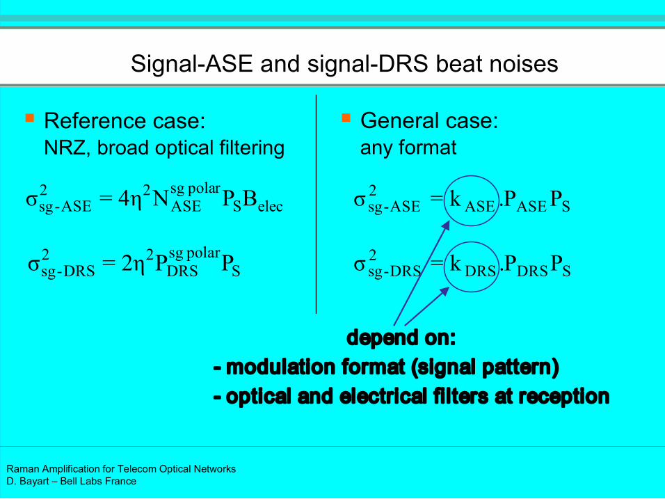
SignalASE and signalDRS beat noises
§ Reference case: NRZ, broad optical filtering
§ General case: any format
elec S r pola sg
ASE 2 2
ASE sg B P N η 4 = σ
S polar sg
DRS 2 2
DRS sg P P η 2 = σ
S ASE ASE 2
ASE sg P P . k = σ
S DRS DRS 2
DRS sg P P . k = σ
depend on: modulation format (signal pattern) optical and electrical filters at reception

Raman Amplification for Telecom Optical Networks D. Bayart – Bell Labs France
Conclusion on DoubleRaleigh Scattering
DRS is a major limitation of the maximum Raman gain that can be obtained in the line fiber Limits Raman advantage in backward pumping
Max gain closed to 23 dB
For all Raman pumping of the line fiber Need for forward pumping
ü See related issues (RIN, …)
Or use of Raman pumping into the DCF ü Increases nonlinear effects in the DCF

Raman Amplification for Telecom Optical Networks D. Bayart – Bell Labs France
Pumptosignal RIN transfer
Raman effect is very fast (femtosecond)
Locally, the intensity fluctuations of the pump are totally
transferred to the signal by gain (dB)
Effect averaged
by counter propagation (backward pumping)
only by chromatic dispersion for forward pumping

Raman Amplification for Telecom Optical Networks D. Bayart – Bell Labs France
Transfer functions
pumping rd for forwa 1 1 2
and
pumping backward for 4
with
1 log 10 ) 10 ln( / 10
log 20 ) ( 2
/
−
=
=
+ −
+ =
P S
P c
S P c
c
OFF ON P S
V V
f
V f
f f G
RIN f RIN
π
α π
α
Assumptions: Distributed Raman amplification: long fiber (50 100km) Moderate Raman gain, moderate pump RIN No pump depletion
Reference: C. R. S. Fludger and al., Electron. Lett., 2001, 37, (1), pp. 1517

Raman Amplification for Telecom Optical Networks D. Bayart – Bell Labs France
135
130
125
120
115
110
1E+ 0 1E+ 3 1E+ 6 1E+ 9 1E+ 12
Frequency (Hz)
RIN (dB/H
z)
Pump RIN
50 kHz 7 GHz
+ 20log(Gonoff/ 4.34)
Transfer functions
With: RIN P =120dB/Hz Gonoff =10dB α P =0.25 dB λ P =1450nm λ S =1550nm
Signal RIN with backward pumping (f c =900 Hz)
Signal RIN with forward pumping SMF (f c =6 MHz) Teralight (f c =18 MHz) may happen with TW and LEAF

Raman Amplification for Telecom Optical Networks D. Bayart – Bell Labs France
Raman amplification : Implementation
Use of wavelength multiplexed Raman pumps
Efficiency depends on fiber type and characteristics
4 pumps (distributed Raman ampli.)
#1 #63
MZ Q
Q
DCF
C
L
DCF
C
L
C
L DCF
x 3
Rx
100 km NZDSF 1x
32
#2 #64
MZ 1x32
40Gb/s 2 15 1
#65 #127
MZ Q
Q
DCF 1x32
#66 #128
MZ 1x32
40Gb/s 2 23 1
PBS
PBS

Raman Amplification for Telecom Optical Networks D. Bayart – Bell Labs France
Stimulated Raman Scattering
17
22
27
5
0
5 In span 5
0 5
27
22
17 Out span
18
13
8
Wavelength (nm) 1525 1605 1427 1565 1485 1439 1450
8
13
18
23 THz
Pretilt ≈3dB
Intrabandtilt compensated but CtoL energytransfer
Raman gain 12dB Cband
10dB Lband
Out span
Pumps OFF
Pumps ON
P
(dBm
)

Raman Amplification for Telecom Optical Networks D. Bayart – Bell Labs France
All Raman pumping schemes
Raman pump
MUX TAP
DCF
DRA in the link:
DRA in the link & DCF:
MUX TAP
Raman pump
MUX TAP
DCF
Raman pump
31dB onoff Raman gain in the link fiber
21.5dB onoff Raman gain in the link fiber
3dB net gain in the DCF (11dB onoff gain)
MUX
Raman pump
MUX
Raman pump

Raman Amplification for Telecom Optical Networks D. Bayart – Bell Labs France
Final impairment of the amplifier on the system:
Achievable distance is proportional to → Parameter C = C noise .C phase (the smaller the better)
Copumping issues to be accounted aside
Criteria for performance assessment (ULH)
in DRS elec ASE noise P R B N C .9 5 *
2 1
+ =
∫ = L
Net phase dz z G γ C 0
) (
Generation of noise
Nonlinear phase
2 / 1 ) ( − phase noise C C

Raman Amplification for Telecom Optical Networks D. Bayart – Bell Labs France
AllRaman transmission of 6 Tbit/s over 6120 km
All Raman amplification (First+Second order)
x3
GFF GFF
+D +D
D
GFF
GFF
Dyn. Gain Equalizer
Link fiber
Tx 149x43Gbit/s Rx
C
L L
C
12 = 6120km
Dyn. Gain Equalizer
Polarization scrambler
Lumped Raman amp.
Lumped Raman amp.

Raman Amplification for Telecom Optical Networks D. Bayart – Bell Labs France
Experimental results with allRaman amplification Spectrum after 6,120km with 149 DPSK channels
In Cband: more odd than even channels Gain excursion close to 10 dB after 6120km OSNR_0.1nm > 16.9dB in L band OSNR_0.1nm > 14.6 dB in C band
Pow
er
10dB
/div.
Wavelength (nm)
1530 1550 1590 1610 1570
Cband Lband
Raman Amplification for Telecom Optical Networks D. Bayart – Bell Labs France
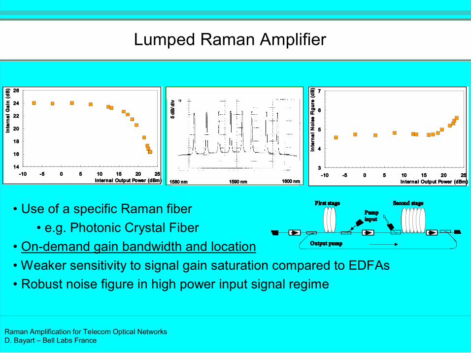
Lumped Raman Amplifier
5 dB
/div
1580 nm 1600 nm 1590 nm
14
16
18
20
22
24
26
10 5 0 5 10 15 20 25 Internal Output Power (dBm)
Internal Gain (dB)
3
4
5
6
7
10 5 0 5 10 15 20 25 In ternal Output Power (dBm)
Internal Noise Figure (dB)
• Use of a specific Raman fiber • e.g. Photonic Crystal Fiber
• Ondemand gain bandwidth and location • Weaker sensitivity to signal gain saturation compared to EDFAs • Robust noise figure in high power input signal regime
Fir st stage
Pump input
Output pump
Second stage Fir st stage
Pump input
Output pump
Second stage

Raman Amplification for Telecom Optical Networks D. Bayart – Bell Labs France
Bibliography
« Erbiumdoped fiber amplifier, Principles and Applications »
Emmanuel Desurvire, Wiley (1994), NewYork
« Erbiumdoped fiber amplifier, Device and System Developments »,
Emmanuel Desurvire, Dominique Bayart, Bertrand Desthieux, Sébastien Bigo,
Wiley (2002), NewYork
« Undersea Fiber Communications Systems »
José Chesnoy Ed., Elsevier, San Diego (2002)
Chap. 4, Optical Amplification, Dominique Bayart