Steam Point Boilers & Heaters Private Limited, Indore, Boilers Burners
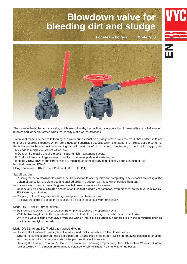
Blowdown valve for bleeding dirt and sludge
Model 260For steam boilers
The water in the boiler contains salts, which are built up by the continuous evaporation. If these salts are not eliminated, bubbles and foam are formed when the density of the water increases.
To prevent these lime deposits forming, the water supply must be suitably treated, with the result that certain salts are changed producing impurities which form sludge and encrusted deposits which then adhere to the sides or the bottom of the boiler and to the combustion tubes, together with particles of dirt, remains of electrodes, carbonic acid, oxygen, etc. This leads to a high level of rust which may:
Destroy the metal plate of the boiler, causing high maintenance costs.Produce thermic voltages, causing cracks in the metal plate and soldering cord.Notably slow down thermic transmission, meaning an unnecessary and excessive consumption of fuel.
Nominal pressure: PN-40.Flange connection: DN-20, 25, 32, 40 and 50 (EN-1092-1).
Specifications— Pushing the pedal downwards causes the drain section to open quickly and completely. The deposits collecting at the
botton of the boiler, are disturbed and sucked up by the sudden air intake which carries them out. — Instant closing device, preventing irrevocable losses of water and pressure.— Seating and closing axis treated and balanced, so that a degree of tightness, even higher than the level required by— EN 12266-1, is obtained.— Coupling of the closing axis is self-tightening and maintenance free.— To solve problems of space, the pedal can be positioned vertically or horizontally.
Model DN-20 and 25. (Pedal driven).— By moving the blocking lever towards the emptying position, the opening blocks.— With the blocking lever in the opposite direction to that of the passage, the valve is in manual drive. — When the valve is being manually driven and with an interlocking gudgeon, it can be fixed in the continuous draining
position for emptying the boiler.
Model DN-32, 40 and 50. (Pedal and flywheel driven).— Rotating the flywheel towards (C) all the way round, locks the valve into the closed position. — Driving the flywheel between the closed position (C) and the central buffer (“Clic”) an emptying position is obtained,
with the pedal, which is proportionate to the pitch section which we set.— Rotating the flywheel towards (A), the valve stays open increasing progressively, the pitch section. When it will go no
further towards (A), a maximum opening is obtained which facilitates the emptying of the boiler.
EN

(1) For DN-20 and 25.
(2) For DN-32, 40 and 50.
(3) For DN-32 a 50 Cast steel (EN-1.0037 S235JR).
DN 20 25 32 40 50
H 180 180 237 237 237
H1 438 438 464 464 464
h — — 78 80 86
L 150 160 180 200 230
L1 275 275 320 320 320
B — — 200 200 200
D 105 115 140 150 165
K 75 85 100 110 125
I 14 14 18 18 18
b 18 18 18 18 20
DRILLS N°. 4 4 4 4 4
WEIGHT IN kgs. 11,12 12,13 20,20 20,22 22,14
CODE 2103-260.8344 2103-260.8104 2103-260.8144 2103-260.8124 2103-260.8204
Efficiency and EmptyingBleeding processes should coincide as far as possible with moments when the water is at rest or at minimum steam extraction, so that the deposits are collected at the bottom of the boiler. Carry out bleeding process at least every 8 hours. The effective duration is estimated to be3 ÷ 4 seconds although we recommend you keep to the following mathematical model:To establish the salinity of the water, the quantity of salts extracted per unit of time must be equal to that of the water supply in this same period. Which can be expressed:
M • A = S • PWhere:Q = Real steam production of the boiler. (Kg/h).A = Water supply. (l/h).M = Salinity of the water supply. (mg/l).P = Water extracted in the bleeding process. (l/h).S = Desired salinity inside the boiler. (mg/l).S = Specific mass of water inside the boiler. (Kg/l).p = Working pressure. (bar).
Example:Q = 1.520 Kg/h.M = 200 mg/l.S = 4.000 mg/l.S = 1 Kg/l.p = 3 bar.
P = 80 l/h
C = 8 l/s.
T = 10s.
The boiler will bleed itself
for 10 seconds every hour.
If the bleeding time is of 3
seconds = 3 bleeding every
hour. The interval between
bleeding should be of 20
minutes.
The water to be bled compared to the steam produced is:
(S-M) • P =
M• Q
For the DN the volume (C) in l/s can be calculated as shown in the diagram.The quotient (P/C) tells us the intervals between bleeding proces-ses and the duration of them (T) in seconds per hour.
Boiler pressure in bar
Vol
ume
in l
/s
The combination of the Continuous desalting valve* and the Blowdown valve for bleeding dirt and sludge• is essential for optimizing the boiler’s efficiency, and include its maximum security and availability.
Neither of them can be replaced with others not designed for this specific application.Their moderate cost is depreciated in the short term.
* (See brochure for Models 560 and 560-A).
• (See brochure for Models 460 and 260-A).
N°. PIECE PIECE MATERIAL
1 Body Cast steel (EN-1.0619)2 Headstock Nodular iron (EN-5.3106)3 Spring press Nodular iron (EN-5.3106
4, 5 Bracket Nodular iron (EN-5.31066 Cap (3) Carbon steel (EN-1.1191)7 Seating Stainless steel (EN-1.4028)8 Axis Stainless steel (EN-1.4028)9 Buffer axis Carbon steel (EN-1.1181)
10 Leading axis Carbon steel (EN-1.1181)11 Removal coupling Carbon steel (DIN-1.0308)
12, 29 Valve base Carbon steel (DIN-1.0308)13 Spring Spring steel (EN-10270-SH)14 Gland Bronze (EN-CC491K-GZ)15 Ring Bronze (EN-CC491K-GZ)16 Pedal (1) Carbon steel (EN-1.1141)
(2) Nodular iron (EN-5.310617, 21, 27, 45, 46 Nut Carbon steel (EN-1.1141)
18, 40 Gudgeon Carbon steel (EN-1.1141)19, 37, 38 Screw Carbon steel (EN-1.1191)
20 Elastic gudgeon Carbon steel (EN-1.1231)22 Retene E.P.D.M.23 Cover joint PTFE (Topchem)
24, 25 Stud Carbon steel (EN-1.1181)26 Dowel Carbon steel (EN-1.1181)28 Valve base Bronze (EN-CC491K-GZ)30 Flywheel Cast iron (EN-5.1300)
31, 34 Buffer Stainless steel (EN-1.4028)32 Buffer ring Carbon steel (EN-1.1141)33 Ring Molybdenum chrome steel (EN-1.7223)
35, 36, 39, 43, 44 Washer Carbon steel (EN-1.1141)41 Lever Nodular iron (EN-5.310642 Leading axis Stainless steel (EN-1.4028)
DN 25 to 50
PN 40
OPERATINGCONDITIONS
PRESSURE IN bar 40 35 32
MAXIMUM TEMP. IN °C 120 200 250
Informative brochure, without obligation and subject to our General Sales Conditions.
+34 93 735 76 90 [email protected] del Daví, 22 Pol. Ind. Can Petit 08227 TERRASSA (Barcelona) SPAINwww.vycindustrial.com
Founded in 1914