
For Professional Clients Only Business Relief and Loan Trusts

X-Lock Theft Deterrent SystemSecurity Code
— — — —Serial # _ _ _ _ _ _ _ _ _ _
0208 © 2006 Titan Tool Inc. All rights reserved. Form No. 313-2651CPrinted in the U. S. A.
Do not use this equipment before reading this manual!
1140ix DigitalAirless Sprayer
Owner’s ManualFor professional use only
NOTE: This manualcontains importantwarnings andinstructions. Pleaseread and retain forreference.
Model Number:High Rider Bare 800-3030High Rider Loaded 800-3035Low Rider Bare 800-3040Low Rider Loaded 800-3045

2 © Titan Tool Inc. All rights reserved.
This symbol indicates a hazardous situation,which, if not not avoided could result in death orserious injury.
To reduce the risks of fire or explosion, electricalshock and the injury to persons, read and under-stand all instructions included in this manual. Befamiliar with the controls and proper usage of theequipment.
HAZARD: INJECTION INJURY
A high pressure paint stream produced by thisequipment can pierce the skin and underlyingtissues, leading to serious injury and possibleamputation. See a physician immediately.DO NOT TREAT AN INJECTION INJURY AS A SIMPLECUT! Injection can lead to amputation. See a physicianimmediately.The maximum operating range of the sprayer is 3300 PSI / 22.8MPa fluid pressure.
PREVENTION:• NEVER aim the gun at any part of the body. • Do not aim the gun at, or spray any person or animal.• NEVER allow any part of the body to touch the fluid stream.
DO NOT allow body to touch a leak in the fluid hose.• NEVER put your hand in front of the gun. Gloves will not
provide protection against an injection injury.• ALWAYS lock the gun trigger, shut the pump off, and
release all pressure before servicing, cleaning the tip orguard, changing tip, or leaving unattended. Pressure willnot be released by turning off the motor. ThePRIME/SPRAY valve or pressure bleed valve must beturned to their appropriate positions to relieve systempressure. Refer to the PRESSURE RELIEFPROCEDURE described in this manual.
• ALWAYS keep the tip guard in place while spraying. Thetip guard provides some protection but is mainly awarning device.
• ALWAYS remove the spray tip before flushing or cleaningthe system.
• Paint hose can develop leaks from wear, kinking andabuse. A leak can inject material into the skin. Inspectthe hose before each use. Do not use hose to lift or pullequipment.
• NEVER use a spray gun without a working trigger lockand trigger guard in place.
• All accessories must be rated at or above 3300 PSI / 22.8MPa. This includes spray tips, guns, extensions, and hose.
• Do not leave the unit energized or under pressure whileunattended. When the unit is not in use, turn off the unitand relieve the pressure in accordance with thePRESSURE RELIEF PROCEDURE described in thismanual.
• Verify that all connections are secure before operating theunit. Unsecured parts may eject at great force or leak ahigh pressure fluid stream causing severe injury.
• Always engage the trigger lock when not spraying. Verifythe trigger lock is functioning properly.
NOTE TO PHYSICIAN:Injection into the skin is a traumatic injury. It isimportant to treat the injury as soon as possible. DONOT delay treatment to research toxicity. Toxicity is aconcern with some coatings injected directly into theblood stream. Consultation with a plastic surgeon orreconstructive hand surgeon may be advisable.
HAZARD: HAZARDOUS VAPORSPaints, solvents, insecticides, and other materials canbe harmful if inhaled or come in contact with the body.Vapors can cause severe nausea, fainting, orpoisoning.
PREVENTION:• Use a respirator or mask if vapors can be
inhaled. Read all instructions supplied with themask to be sure it will provide the necessaryprotection.
• Wear protective eyewear.• Wear protective clothing as required by coating
manufacturer.
HAZARD: EXPLOSION OR FIRE Solvent and paint fumes can explode or ignite.Property damage and/or severe injury can occur.
PREVENTION:• Provide extensive exhaust and fresh air introduction to
keep the air within the spray area free from accumulationof flammable vapors. Solvent and paint fumes canexplode or ignite.
• Do not spray in a confined area.• Avoid all ignition sources such as static electric
sparks, open flames, pilot lights, electricalappliances, and hot objects. Connecting or disconnectingpower cords or working light switches can make sparks.Paint or solvent flowing through the equipment is able toresult in static electricity.
• Do not smoke in spray area.• Fire extinguisher must be present and in good working
order.• Place pump at least 25 feet (7.62 meters) from the spray
object in a well ventilated area (add more hose ifnecessary). Flammable vapors are often heavier than air.Floor area must be extremely well ventilated. The pumpcontains arcing parts that emit sparks and can ignitevapors.
• The equipment and objects in and around the spray areamust be properly grounded to prevent static sparks.
• Keep area clean and free of paint or solvent containers,rags and other flammable materials.
• Use only conductive or grounded high pressure fluid hose.Gun must be grounded through hose connections.
• For electric units — power cord must be connected to agrounded circuit.
• Always flush unit into a separate metal container, at lowpump pressure, with spray tip removed. Hold gun firmlyagainst side of container to ground container and preventstatic sparks.
• Follow the material and solvent manufacturer's warningsand instructions. Know the contents of the paints andsolvents being sprayed. Read all Material Safety DataSheets (MSDS) and container labels provided with thepaints and solvents. Follow the paint and solventmanufacturer’s safety instructions.
• Use extreme caution when using materials with aflashpoint below 70ºF (21ºC). Flashpoint is thetemperature that a fluid can produce enough vapors toignite.
• Plastic can cause static sparks. Never hang plastic toenclose a spray area. Do not use plastic drop clothswhen spraying flammable materials.
• Use lowest possible pressure to flush equipment.• Do not spray onto pump assembly.
Important Safety Information • Read all safety information before
operating the equipment. Save these instructions.

© Titan Tool Inc. All rights reserved. 3
HAZARD: EXPLOSION HAZARD DUE TOINCOMPATIBLE MATERIALS
Will cause property damage or severe injury.
PREVENTION:• Do not use materials containing bleach or chlorine.• Do not use halogenated hydrocarbon solvents such as
bleach, mildewcide, methylene chloride and 1,1,1 -trichloroethane. They are not compatible with aluminum.
• Contact your coating supplier about the compatibility ofmaterial with aluminum.
HAZARD: GENERALCan cause severe injury or property damage.
• Read all instructions and safety precautions beforeoperating equipment.
• Follow all appropriate local, state, and national codesgoverning ventilation, fire prevention, and operation.
• The United States Government Safety Standards havebeen adopted under the Occupational Safety and HealthAct (OSHA). These standards, particularly part 1910 ofthe General Standards and part 1926 of the ConstructionStandards should be consulted.
• Use only manufacturer authorized parts. User assumesall risks and liabilities when using parts that do not meetthe minimum specifications and safety requirements of thepump manufacturer.
• All hoses, fittings, and filter parts must be secured beforeoperating spray pump. Unsecured parts can eject at greatforce or leak a high pressure fluid stream causing severeinjury.
• Before each use, check all hoses for cuts, leaks, abrasionor bulging of cover. Check for damage or movement ofcouplings. Immediately replace the hose if any of theseconditions exist. Never repair a paint hose. Replace itwith another grounded high-pressure hose.
• Do not kink or over-bend the hose. Airless hose candevelop leaks from wear, kinking and abuse. A leak caninject material into the skin.
• Do not expose the hose to temperatures or pressures inexcess of those specified by manufacturer.
• Do not spray outdoors on windy days.• Wear clothing to keep paint off skin and hair.• Do not operate or spray near children. Keep children
away from the equipment at all times.• Do not overreach or stand on an unstable support. Keep
effective footing and balance at all times.• Use lowest possible pressure to flush equipment.• Stay alert and watch what you are doing.• Do not operate the unit when fatigued or under the
influence of drugs or alcohol.• For electric units — Always unplug cord from outlet before
working on equipment.• Do not use the hose as a strength member to pull or lift
the equipment.• Do not lift by cart handle when loading or unloading.
Grounding InstructionsThis product must be grounded. In the event of an electricalshort circuit, grounding reduces the risk of electric shock byproviding an escape wire for the electric current. This productis equipped with a cord having a grounding wire with anappropriate grounding plug. The plug must be plugged into anoutlet that is properly installed and grounded in accordancewith all local codes and ordinances.
Improper installation of the grounding plugcan result in a risk of electric shock.
If repair or replacement of the cord or plug is necessary, do notconnect the green grounding wire to either flat blade terminal.The wire with insulation having a green outer surface with orwithout yellow stripes is the grounding wire and must beconnected to the grounding pin.Check with a qualified electrician or serviceman if thegrounding instructions are not completely understood, or if youare in doubt as to whether the product is properly grounded.Do not modify the plug provided. If the plug will not fit theoutlet, have the proper outlet installed by a qualifiedelectrician.
IMPORTANT: Use only a 3-wire extension cord that has a3-blade grounding plug and a 3-slot receptacle that willaccept the plug on the product. Make sure your extensioncord is in good condition. When using an extension cord,be sure to use one heavy enough to carry the current yourproduct will draw. An undersized cord will cause a dropin line voltage resulting in loss of power and overheating.A 12 gauge cord is recommended. If an extension cord isto be used outdoors, it must be marked with the suffix W-A after the cord type designation. For example, adesignation of SJTW-A would indicate that the cord wouldbe appropriate for outdoor use.
IMPORTANT: When the sprayer is used with a generatoror uncontrolled line voltage, the use of Titan’s “Line SurgeProtector” (P/N 800-935) is recommended.
SpecificationsGallons per minute (GPM) ...............1.2 (4.5 LPM)Maximum tip sizes ...........................one gun = 0.034”
two guns = 0.023”Maximum pressure ..........................3300 PSI (22.8 MPa)Voltage .............................................100~120V AC, 50/60 HzPower................................................2.4 HP Infinity Plus
Brushless® DC MotorMaximum current consumption........15 AWeight ..............................................95 lbs. (43.1 kg)Maximum hose length......................300’ (91.4 m)
Grounded Outlet
Grounding Pin
Cover for grounded outlet box
Important Safety Information • Read all safety information before
operating the equipment. Save these instructions.

Table of ContentsSafety Precautions .................................................................2
Français ..............................................................................16Español ...............................................................................18
General Description ...............................................................4Operation ................................................................................4
Setup ....................................................................................4Preparing to Paint .................................................................5Painting.................................................................................5Control Panel Indicators .......................................................5Xact Digital Control System Operation (if equipped) ............6Pressure Relief Procedure ...................................................7
Spraying ..................................................................................8Spraying Technique ..............................................................8Practice.................................................................................8
Cleanup ...................................................................................9Maintenance............................................................................9
General Repair and Service Notes.......................................9Replacing the Filters...........................................................10Replacing the Motor Assembly ...........................................10Replacing the Gears ...........................................................11Replacing the Transducer ...................................................11Replacing the PRIME/SPRAY Valve...................................12Servicing the Fluid Section .................................................12
Troubleshooting ...................................................................14Xact Digital Control System Error Messages .....................15
Parts Listings........................................................................20Main Assembly....................................................................20Drive Assembly ...................................................................21Fluid Section Assembly ......................................................22High Rider Cart ...................................................................23Filter Assembly ...................................................................23Low Rider Siphon Assembly...............................................24Low Rider Cart....................................................................24Labels .................................................................................24PRIME/SPRAY Assembly ...................................................25Electrical Schematic ...........................................................25Accessories ........................................................................26
Warranty ................................................................................28
General DescriptionThis airless sprayer is a precision power tool used for sprayingmany types of materials. Read and follow this instructionmanual carefully for proper operating instructions,maintenance, and safety information.
OperationThis equipment produces a fluid stream atextremely high pressure. Read and understandthe warnings in the Safety Precautions section atthe front of this manual before operating thisequipment.
Return Hose
Siphon Tube
Pressure Control
Knob
Control Panel
Indicators
Xact Digital Control System
Fluid Section
Filter
Motor
PRIME/ SPRAY Valve
Outlet Fitting
4 © Titan Tool Inc. All rights reserved.
SetupPerform the following procedure before plugging in the powercord of an electric unit.
1. Ensure that the siphon tube and the return hose areattached and secure.
2. Using a wrench, attach a minimum of 50’ of nylon airlessspray hose to the unit. Tighten securely.
3. Attach an airless spray gun to the spray hose. Using twowrenches (one on the gun and one on the hose), tightensecurely.
Make sure all airless hoses and spray guns areelectrically grounded and rated at or above themaximum operating pressure range of the airlesssprayer.
4. Make sure the pressure control knob is in its OFF positionin the black zone.
5. Fill the oil cup with one tablespoon of piston seal lubricant(Piston Lube).
IMPORTANT: Never operate unit for more than tenseconds without fluid. Operating this unit without fluidwill cause unnecessary wear to the packings.
6. Make sure the electrical service is 120V, 15 ampminimum.
7. Plug the power cord into a properly grounded outlet atleast 25’ from the spray area.
IMPORTANT: Always use a minimum 12 gauge, three-wireextension cord with a grounded plug. Never remove thethird prong or use an adapter.
Preparing a New SprayerIf this unit is new, it is shipped with test fluid in the fluid sectionto prevent corrosion during shipment and storage. This fluidmust be thoroughly cleaned out of the system with mineralspirits before you begin spraying.IMPORTANT: Always keep the trigger lock on the spraygun in the locked position while preparing the system.
1. Place the siphon tube into a container of mineral spirits.2. Place the return hose into a metal waste container.3. Set the pressure to minimum by turning the pressure
control knob to the “Min” setting in the yellow zone.
4. Move the PRIME/SPRAY valve down tothe PRIME position.
5. Turn on the sprayer by moving theON/OFF switch to the ON position.
6. Allow the sprayer to run for 15–30 secondsto flush the test fluid out through the returnhose and into the waste container.
7. Turn off the sprayer by moving the ON/OFF switch to theOFF position.
Min PSI (Bar)
Max PSI (Bar)
Blinking Yellow0-200 PSI
Solid Yellow201-1900 PSI
Solid Green 1901-3300 PSI
Motor Running
Pulse
Clean
Min. – 1900 PSI(yellow zone) 1901 – 3300 PSI
(green zone)
Turbo PulseClean (red zone)
OFF (black zone)
Pressure Control Knob
NOTE: Do not attach the tip to the spray gun yet.Remove the tip if it is already attached.

Preparing to PaintBefore painting, it is important to make sure that the fluid in thesystem is compatible with the paint that is going to be used.
IMPORTANT: Always keep the trigger lock on the spraygun in the locked position while preparing the system.
1. Place the siphon tube into a container of the appropriatesolvent. Examples of the appropriate solvent are water forlatex paint or mineral spirits for oil-based paints.
2. Place the return hose into a metal wastecontainer.
3. Set the pressure to minimum by turningthe pressure control knob to the “Min”setting in the yellow zone.
4. Move the PRIME/SPRAY valve down to thePRIME position.
5. Turn on the sprayer by moving the ON/OFF switch to theON position.
6. Allow the sprayer to run for 15–30 seconds to flush the oldsolvent out through the return hose and into the metalwaste container.
7. Turn off the sprayer by moving the ON/OFF switch to theOFF position.
8. Move the PRIME/SPRAY valve up to theSPRAY position.
9. Turn on the sprayer.10. Unlock the gun by turning the gun trigger
lock to the unlocked position.
Ground the gun by holding itagainst the edge of the metalcontainer while flushing. Failureto do so may lead to a staticelectric discharge, which maycause a fire.
11. Trigger the gun into the metal waste container until the oldsolvent is gone and fresh solvent is coming out of the gun.
12. Lock the gun by turning the gun triggerlock to the locked position.
13. Set down the gun and increase thepressure by turning the pressure controlknob slowly clockwise into the greenzone.
14. Check the entire system for leaks. Ifleaks occur, follow the “Pressure Relief Procedure” in thismanual before tightening any fittings or hoses.
15. Follow the “Pressure Relief Procedure” in this manualbefore changing from solvent to paint.
Be sure to follow the pressure relief procedurewhen shutting down the sprayer for any purpose,including servicing or adjusting any part of thespray system, changing or cleaning spray tips, orpreparing for cleanup.
Trigger lock in locked position.
NOTE: Make sure that the spray gun does not have atip or tip guard installed.
NOTE: Hold the return hose in the wastecontainer when moving thePRIME/SPRAY valve to PRIME incase the sprayer is pressurized.
Min PSI (Bar)
Max PSI (Bar)
Pulse
Clean
NOTE: Incompatible fluids and paint may cause thevalves to become stuck closed, which wouldrequire disassembly and cleaning of thesprayer’s fluid section.
Painting1. Place the siphon tube into a container of paint.2. Place the return hose into a metal waste
container.3. Set the pressure to minimum by turning
the pressure control knob to the “Min”setting in the yellow zone.
4. Move the PRIME/SPRAY valve down to thePRIME position.
5. Turn on the sprayer by moving the ON/OFFswitch to the ON position.
6. Allow the sprayer to run until paint iscoming through the return hose into themetal waste container.
7. Turn off the sprayer by moving the ON/OFF switch to theOFF position.
8. Remove the return hose from the waste container andplace it in its operating position above the container ofpaint.
9. Move the PRIME/SPRAY valve up to theSPRAY position.
10. Turn on the sprayer.11. Unlock the gun by turning the gun trigger
lock to the unlocked position.
Ground the gun by holding itagainst the edge of the metalcontainer while flushing. Failureto do so may lead to a staticelectric discharge, which maycause a fire.
12. Trigger the gun into the metal waste container until all airand solvent is flushed from the spray hose and paint isflowing freely from the gun.
13. Lock the gun by turning the gun triggerlock to the locked position.
14. Turn off the sprayer.15. Attach tip guard and tip to the gun as
instructed by the tip guard or tip manuals.
POSSIBLE INJECTION HAZARD.Do not spray without the tip guardin place. Never trigger the gununless the tip is in either the spray or the unclogposition. Always engage the gun trigger lockbefore removing, replacing or cleaning tip.
16. Turn on the sprayer.17. Increase the pressure by turning the pressure control knob
slowly clockwise toward the green zone and test the spraypattern on a piece of cardboard. Adjust the pressurecontrol knob until the spray from the gun is completelyatomized. Try to keep the pressure control knob at thelowest setting that maintains good atomization.
Control Panel IndicatorsThe following is a description of the control panel indicators.
Min PSI (Bar)
Max PSI (Bar)
Blinking Yellow0-200 PSI
Solid Yellow201-1900 PSI
Solid Green 1901-3300 PSI
Motor Running
Pulse
Clean
Pressure Indicator
Motor Running Indicator
NOTE: Turning the pressure up higher then needed toatomize the paint will cause premature tip wearand additional overspray.
Trigger lock in locked position.
Min PSI (Bar)
Max PSI (Bar)
Pulse
Clean
© Titan Tool Inc. All rights reserved. 5
Pressure IndicatorThe pressure indicator shows the current operating pressure ofthe sprayer. It has three different indications: blinking yellow,solid yellow, and solid green.
Blinking YellowWhen the pressure indicator is blinking yellow, the sprayer isoperating between 0 and 200 PSI. A blinking yellow pressureindicator means:
• The sprayer is plugged in and turned “ON”.• The sprayer is at priming pressure (little or no pressure).• It is safe to move the PRIME/SPRAY valve between
positions.• It is safe to change or replace the spray tip.
Solid YellowWhen the pressure indicator is solid yellow, the sprayer isoperating between 200 and 1800 PSI. A solid yellow pressureindicator means:
• The sprayer is at the proper pressure setting for sprayingstain, lacquer, varnish, and multi-colors.
• If the pressure indicator goes to solid yellow when thepressure is set so that it starts at solid green, it indicatesone of the following:a. Tip Wear Indicator — when spraying with latex or at
high pressure the solid yellow appears. This meansthe tip is worn and needs to be replaced.
b. Tip Too Large — when a tip that is too large for thesprayer is put in the gun, the pressure indicator will turnfrom solid green to solid yellow.
c. Fluid Section Wear — if a solid yellow pressureindicator appears when using a new tip and thepressure is set at maximum, service may be required(worn packings, worn piston, stuck valve, etc...).
Solid GreenWhen the pressure indicator is solid green, the sprayer isoperating between 1800 and 3300 PSI. A solid green pressureindicator means:
• The sprayer is at the proper pressure setting for sprayingoil-based and latex house paints.
• The sprayer is operating at peak performance at a highpressure setting.
Motor Running IndicatorThe Motor Running indicator is on when the motor iscommanded to run. This indicator is used by service centersto troubleshoot motor problems.
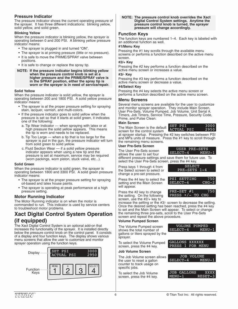
Xact Digital Control System Operation(if equipped)The Xact Digital Control System is an optional add-on thatincreases the functionality of the sprayer. It is installed directlybelow the pressure control knob on the control panel. It consistsof a display and four function keys. The display shows variousmenu screens that allow the user to customize and monitorsprayer operation using the function keys.
SET PSI 3000ACTUAL PSI 2950
MENU + – SELECT
4321
Display
Function Keys
NOTE: If the pressure indicator begins blinking yellowwhen the pressure control knob is set at ahigher pressure and the PRIME/SPRAY valve isin the SPRAY position, either the spray tip isworn or the sprayer is in need of service/repair.
6 © Titan Tool Inc. All rights reserved.
Function KeysThe function keys are numbered 1–4. Each key is labeled withan additional function as well. #1/Menu KeyPressing the #1 key scrolls through the available menuscreens or performs a function described on the active menuscreen.#2/+ KeyPressing the #2 key performs a function described on theactive menu screen or increases a value.#3/- KeyPressing the #3 key performs a function described on theactive menu screen or decrease a value.#4/Select KeyPressing the #4 key selects the active menu screen orperforms a function described on the active menu screen.
Menu ScreensSeveral menu screens are available for the user to customizeand monitor sprayer operation. They include Main Screen,User Pre-Sets, Volume Pumped, Job Volume, Unit Serial #,TImers, Job Timers, Service Time, Pressure, Security Code,Prime, and Pulse Clean.Main ScreenThe Main Screen is the defaultscreen for the control systemat sprayer startup. Pressing the #2 key switches between PSIand MPa units of measure. Press the #1 key to scroll throughthe remaining menu screens.User Pre-Sets ScreenThe User Pre-Sets screenallows the user to set fourdifferent pressure settings and save them for future use. Toselect the User Pre-Sets screen, press the #4 key.
Press keys 1 through 4 fromthe Select screen to select orchange a pre-set pressure.
Press the #4 key to select thesetting and the Main Screenwill appear.
Press the #2 key to changethe setting. On the followingscreen, use the #2/+ key toincrease the setting or the #3/- screen to decrease the setting.Once the desired setting has been reached, press the #4 keyto set and the Main Screen will appear. To select or changethe remaining three pre-sets, scroll to the User Pre-Setsscreen and repeat the above procedure.Volume Pumped Screen
The Volume Pumped screenshows the total number ofgallons or liters sprayed by thesprayer.
To select the Volume Pumpedscreen, press the #4 key.
Job Volume Screen
The Job Volume screen allowsthe user to reset a galloncounter to track usage onspecific jobs.
To select the Job Volumescreen, press the #4 key.
JOB GALLONS XXXXMENU-1 RESET-3
JOB VOLUMESELECT-4 MENU-1
GALLONS XXXXXXPRESS 1 FOR MENU
VOLUME PUMPEDSELECT-4 MENU-1
PRE-SET #1 750PRESS +/- TO CHG
PSI SETTING 750SELECT-4 CHG-2
SELECTPRE-SETS 1-4
USER PRE-SETSSELECT-4 MENU-1
SET PSI 3000ACTUAL PSI 2950
NOTE: The pressure control knob overrides the XactDigital Control System settings. Anytime thepressure control knob is turned, the sprayerpressure will change accordingly.

Unit Serial # Screen
The Unit Serial # screenshows the sprayers serialnumber.
To select the Unit Serial #screen, press the #4 key.
Timers Screen
The Timers screen shows thetotal time the sprayer has beenturned on as well as the totaltime the sprayer has been running (pumping).
To select the Timers screen,press the #4 key.
Job Timers Screen
The Job Timers screen allowsthe user to reset the “ONTIME” and “RUN TIME” totrack time on specific jobs.
To select the Job TImersscreen, press the #4 key. Thescreen will toggle between thetimers and a screen that allows the user to reset the timers.
Service Time Screen
The Service Time screenallows the user to set a servicetime interval (in hours). Belowthe set time, the screens shows the current amount of hourson the sprayer. To select the Service TImer screen, press the#4 key.
The screen will toggle betweenthe service hours and a screenthat allows the user to changethe service time interval.
When the service time interval is set and met by the run hours,the display will toggle between the "Main screen" and a"Service Required" screen at sprayer startup. To stop thetoggling, scroll to the "Service Time" screen and either set anew service time interval or set the service time to "0".
Pressure Screen
The Pressure screen allowsthe user to see the current setpoint pressure as well as theactual working pressure.
To select the Pressure screen,press the #4 key. This screenis also the Main Screen.
Security Code Screen
The Security Code screenallows the user to set a fourdigit security code to preventunauthorized use of the sprayer. If a security code has beenset, the control system display will ask for the code at startup.If the correct code is entered, the display will show the MainScreen and the sprayer will operate. If the wrong code isentered, the display will continue to ask for the correct codeand the sprayer will be disabled. To set or change the securitycode, press the #2 key.
Enter the old security codenumber to access the screenthat allows the code change.If the wrong code is entered, the display will continue to askfor the correct code and the security code cannot be changed.
ENTER OLD CODENUMBER
NOTE: If the sprayer is new, no security code is setand the Main Screen will appear at startup.Also, when setting a security code for the firsttime, the “Enter Old Code Number” screen willnot appear.
SECURITY CODESELECT-4 MENU-1
SET PSI 3000ACTUAL PSI 2950
PRESSURESELECT-4 MENU-1
SERVICE @ XXXHRRUN HOURS XX
SERVICE TIMESELECT-4 MENU-1
ON TIME XXXXX:XXRUN TIME XXXX:XX
JOB TIMERSSELECT-4 MENU-1
ON TIME XXXXX:XXRUN TIME XXXX:XX
TIMERSSELECT-4 MENU-1
SER # XXXXXXXXXXPRESS 1 FOR MENU
UNIT SERIAL #SELECT-4 MENU-1
Enter the new security code.Once the new code is entered,the display will automaticallyask that the new code be re-entered for verification. If thesame new code is re-entered, the display will confirm that thenew code has been accepted and return to the Main Screen.If the new code is re-entered incorrectly, the display will returnto the “Enter New Code Number” screen and the process willrepeat.
Prime ScreenThe Prime screen appearswhen the pressure controlknob is set at the “Min” settingin the yellow zone.
Pulse Clean ScreenThe Pulse Clean screenappears when the pressurecontrol knob is set at thePULSE CLEAN position in the red zone and thePRIME/SPRAY valve is in the PRIME position.
Pressure Relief ProcedureBe sure to follow the pressure relief procedurewhen shutting the unit down for any purpose,including servicing or adjusting any part of thespray system, changing or cleaning spray tips, orpreparing for cleanup.
1. Lock the gun by turning the gun triggerlock to the locked position.
2. Turn off the sprayer by moving theON/OFF switch to the OFF position.
3. Turn the pressure control knobcounterclockwise to its OFF position inthe black zone.
4. Unlock the gun by turning the gun trigger lock to theunlocked position.
5. Hold the metal part of the gun firmly tothe side of a metal container to groundthe gun and avoid a build up of staticelectricity.
6. Trigger the gun to remove any pressurethat may still be in the hose.
7. Lock the gun by turning the gun trigger lockto the locked position.
8. Move the PRIME/SPRAY valve down to thePRIME position.
Trigger lock in locked position.
NOTE: If there is no action at any menu screen for 30seconds, the display will go back to the MainScreen.
PULSE CLEANACTUAL PSI XXXX
PRIME
NOTE: To inactivate the X-Lock security function,enter “1111” at the “Enter New Code Number”screen (this is the default code that leaves thesprayer unlocked). As a result, the MainScreen will appear at sprayer startup.
ENTER NEW CODENUMBER
© Titan Tool Inc. All rights reserved. 7
SprayingPOSSIBLE INJECTION HAZARD. Do not spraywithout the tip guard in place. Never trigger thegun unless the tip is in either the spray or theunclog position. Always engage the gun triggerlock before removing, replacing, or cleaning tip.
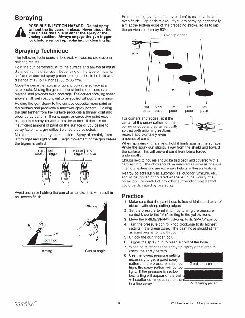
Spraying TechniqueThe following techniques, if followed, will assure professionalpainting results.Hold the gun perpendicular to the surface and always at equaldistance from the surface. Depending on the type of material,surface, or desired spray pattern, the gun should be held at adistance of 12 to 14 inches (30 to 35 cm).Move the gun either across or up and down the surface at asteady rate. Moving the gun at a consistent speed conservesmaterial and provides even coverage. The correct spraying speedallows a full, wet coat of paint to be applied without runs or sags.Holding the gun closer to the surface deposits more paint onthe surface and produces a narrower spray pattern. Holdingthe gun farther from the surface produces a thinner coat andwider spray pattern. If runs, sags, or excessive paint occur,change to a spray tip with a smaller orifice. If there is aninsufficient amount of paint on the surface or you desire tospray faster, a larger orifice tip should be selected.Maintain uniform spray stroke action. Spray alternately fromleft to right and right to left. Begin movement of the gun beforethe trigger is pulled.
Avoid arcing or holding the gun at an angle. This will result inan uneven finish.
Too Thick
Offspray
Arcing Gun at angle
start stroke
release trigger
pull trigger
end stroke
8 © Titan Tool Inc. All rights reserved.
Proper lapping (overlap of spray pattern) is essential to aneven finish. Lap each stroke. If you are spraying horizontally,aim at the bottom edge of the preceding stroke, so as to lapthe previous pattern by 50%.
For corners and edges, split thecenter of the spray pattern on thecorner or edge and spray verticallyso that both adjoining sectionsreceive approximately evenamounts of paint.When spraying with a shield, hold it firmly against the surface.Angle the spray gun slightly away from the shield and towardthe surface. This will prevent paint from being forcedunderneath.Shrubs next to houses should be tied back and covered with acanvas cloth. The cloth should be removed as soon as possible.Titan gun extensions are extremely helpful in these situations.Nearby objects such as automobiles, outdoor furniture, etc.should be moved or covered whenever in the vicinity of aspray job. Be careful of any other surrounding objects thatcould be damaged by overspray.
Practice1. Make sure that the paint hose is free of kinks and clear of
objects with sharp cutting edges.3. Set the pressure to minimum by turning the pressure
control knob to the “Min” setting in the yellow zone.3. Move the PRIME/SPRAY valve up to its SPRAY position.4. Turn the pressure control knob clockwise to its highest
setting in the green zone. The paint hose should stiffenas paint begins to flow through it.
5. Unlock the gun trigger lock.6. Trigger the spray gun to bleed air out of the hose.7. When paint reaches the spray tip, spray a test area to
check the spray pattern.8. Use the lowest pressure setting
necessary to get a good spraypattern. If the pressure is set toohigh, the spray pattern will be toolight. If the pressure is set toolow, tailing will appear or the paintwill spatter out in gobs rather thanin a fine spray.
Good spray pattern
Paint tailing pattern
Overlap edges
1st pass
2nd pass
3rd pass
4th pass
5th pass

CleanupSpecial cleanup instructions for use withflammable solvents:
• Always flush spray gun preferably outside and at least onehose length from spray pump.
• If collecting flushed solvents in a one gallon metalcontainer, place it into an empty five gallon container, thenflush solvents.
• Area must be free of flammable vapors.• Follow all cleanup instructions.
IMPORTANT: The sprayer, hose, and gun should becleaned thoroughly after daily use. Failure to do sopermits material to build up, seriously affecting theperformance of the unit.
Always spray at minimum pressure with the gunnozzle tip removed when using mineral spirits orany other solvent to clean the sprayer, hose, orgun. Static electricity buildup may result in a fireor explosion in the presence of flammable vapors.
1. Follow the “Pressure Relief Procedure” found in theOperation section of this manual.
2. Remove the gun tip and tip guard and clean with a brushusing the appropriate solvent.
3. Place the siphon tube into a container of the appropriatesolvent. Examples of the appropriate solvent are water forlatex paint or mineral spirits for oil-based paints.
4. Place the return hose into a metal waste container.5. Move the PRIME/SPRAY valve down to its
PRIME position.
6. Set the pressure to Turbo PulseClean byturning the pressure control knob to itsPULSE CLEAN position in the red zone.
7. Turn on the sprayer by moving the ON/OFFswitch to the ON position.
8. Allow the solvent to circulate through the unit and flush thepaint out of the return hose into the metal waste container.
9. Turn off the sprayer by moving theON/OFF switch to the OFF position.
10. Move the PRIME/SPRAY valve up to itsSPRAY position.
11. Turn on the sprayer.
Ground the gun by holding itagainst the edge of the metalcontainer while flushing. Failure todo so may lead to a static electricdischarge, which may cause a fire.
12. Trigger the gun into the metal waste container until thepaint is flushed out of the hose and solvent is coming outof the gun.
13. Continue to trigger the spray gun into the waste containeruntil the solvent coming out of the gun is clean.
14. Follow the “Pressure Relief Procedure” found in theOperation section of this manual.
15. Unplug the sprayer and store in a clean, dry area.
IMPORTANT: Do not store the unit under pressure.
NOTE: For long-term or cold weather storage, pumpmineral sprits through the entire system.For short-term storage when using latex paint,pump water mixed with Titan Liquid Shield Plusthrough the entire system (see the Accessoriessection of this manual for part number).
Min PSI (Bar)
Max PSI (Bar)
Pulse
Clean
NOTE: Hold the return hose in the wastecontainer when moving thePRIME/SPRAY valve to PRIME incase the sprayer is pressurized.
© Titan Tool Inc. All rights reserved. 9
MaintenanceBefore proceeding, follow the Pressure ReliefProcedure outlined previously in this manual.Additionally, follow all other warnings to reducethe risk of an injection injury, injury from movingparts or electric shock. Always unplug thesprayer before servicing!
General Repair and Service NotesThe following tools are needed when repairing this sprayer:
Phillips Screwdriver 3/8" Hex WrenchNeedle Nose Pliers 5/16" Hex WrenchAdjustable Wrench 1/4" Hex WrenchRubber Mallet 3/16" Hex WrenchFlat-blade Screwdriver 5/32” Hex Wrench
1. Before repairing any part of the sprayer, read theinstructions carefully, including all warnings.
IMPORTANT: Never pull on a wire to disconnect it. Pullingon a wire could loosen the connector from the wire.
2. Test your repair before regular operation of the sprayer tobe sure that the problem is corrected. If the sprayer doesnot operate properly, review the repair procedure todetermine if everything was done correctly. Refer to theTroubleshooting Charts to help identify other possibleproblems.
3. Make certain that the service area is well ventilated incase solvents are used during cleaning. Always wearprotective eyewear while servicing. Additional protectiveequipment may be required depending on the type ofcleaning solvent. Always contact the supplier of solventsfor recommendations.
4. If you have any further questions concerning your TITANAirless Sprayer, call TITAN:
Customer Service (U.S.) .......................1-800-526-5362Fax ................................................1-800-528-4826
Customer Service (Canada)..................1-800-565-8665Fax ................................................ 1-905-856-8496
Customer Service (International)...........1-201-337-1240Fax ................................................1-201-405-7449

Replacing the Filters Pump Filter
1. Loosen and remove the filterbody by hand.
2. Slip the filter off of the corespring.
3. Inspect the filter. Based oninspection, clean or replacethe filter.
4. Inspect the o-ring. Based oninspection, clean or replacethe o-ring.
5. Slide the new or cleanedfilter over the core springwith the filter spring adapterin place. Push the filter intothe center of the filterhousing.
6. Slide the filter body over thefilter and thread it into thefilter housing until secure.
Gun Filter1. Move the gun trigger lock to the unlocked position.2. Loosen and remove the handle from the gun body.3. Turning clockwise, unscrew the filter from the gun body.
4. Turning counterclockwise, screw the new or cleaned filterinto the gun body.
5. Make sure the handle seal is in position and thread thehandle into the gun body until secure.
6. Move the gun trigger lock to the locked position.
NOTE: For more detail, part number information, andcomplete assembly drawings, please see theLX-80II Professional Airless Gun Owner'sManual (P/N 313-2293).
Handle
Handle Seal
Filter
Gun Body
NOTE: Left-handed threads require turning the filterclockwise to remove.
NOTE: The filter bodyshould be hand-tightened, but makesure it is seatedfully into the filterhousing.
Filter Body
Filter Spring
Filter Spring Adapter
Core Spring
Filter
O-ring
Filter Housing
10 © Titan Tool Inc. All rights reserved.
Replacing the Motor Assembly1. Unplug the unit.2. Loosen and remove the four motor shroud screws.
Remove the motor shroud.3. Release the tie wrap on the top of the baffle assembly and
slip the baffle assembly down off of the motor.4. Loosen and remove the three electronic cover screws.
Lift the electronic cover off of the electronic controlassembly on the motor.
5. Disconnect all wires between the motor and the sprayer.6. Loosen and remove the three motor mounting screws.7. Pull the motor out of the gearbox housing.8. With the motor removed, inspect the gears in the gearbox
housing for damage or excessive wear. Replace thegears, if necessary.
9. Install the new motor into the gearbox housing. Makesure the housing gasket is positioned properly.
10. Secure the motor with the three motor mounting screws.11. Reconnect the wires between the sprayer and the new
motor. (refer to the electrical schematic in the Parts Listsection of this manual).
12. Position the electronic cover over the electronic controlassembly. Secure the electronic cover with the threeelectronic cover screws.
13. Slip the baffle assembly up and around the motor. Securethe baffle assembly with the tie wrap.
14. Slide the motor shroud over the motor. Make sure theshroud gasket is positioned properly.
15. Secure the motor shroud with the four motor shroudscrews.
Electronic Cover
Motor Shroud
Motor Shroud Screws
Motor
Baffle Assembly
Housing Gasket
Shroud Gasket
Electronic ControlAssembly
Motor Mounting Screw
Electronic Cover Screw
Gearbox Housing

Replacing the Gears1. Unplug the unit.2. Loosen and remove the four motor shroud screws.
Remove the motor shroud.3. Release the tie wrap on the top of the baffle assembly and
slip the baffle assembly down off of the motor.4. Loosen and remove the three electronic cover screws.
Lift the electronic cover off of the electronic controlassembly on the motor.
5. Disconnect all wires between the motor and the sprayer.6. Loosen and remove the three motor mounting screws.7. Pull the motor out of the gearbox housing.8. Inspect the armature gear on the end of the motor for
damage or excessive wear. If this gear is completelyworn out, replace the front end bell assembly.
9. Remove and inspect the 1st stage gear and 2nd stagegear assemblies for damage or excessive wear. Replace,if necessary.
10. Remove and inspect the front gear box assembly fordamage or excessive wear. If damaged or worn, replacethe front gear box assembly.
11. Install the motor into the gearbox housing. Make sure thehousing gasket is positioned properly.
12. Secure the motor with the three motor mounting screws.13. Reconnect the wires between the sprayer and the motor.
(refer to the electrical schematic in the Parts List sectionof this manual).
14. Position the electronic cover over the electronic controlassembly. Secure the electronic cover with the threeelectronic cover screws.
15. Slip the baffle assembly up and around the motor. Securethe baffle assembly with the tie wrap.
16. Slide the motor shroud over the motor. Make sure theshroud gasket is positioned properly.
17. Secure the motor shroud with the four motor shroudscrews.
Front End Bell Assembly
Armature Gear
1st Stage Gear
2nd Stage Gear
Front Gear Box Assembly Housing
Gasket
Shroud Gasket
NOTE: Clean and refill the gear box cavity up to the rearface of each gear with Lubriplate (P/N 314-171).
Replacing the Transducer1. Unplug the unit.2. Loosen and remove the four motor shroud screws.
Remove the motor shroud.3. At the electronic control assembly, disconnect the wire
coming from the transducer.4. Pull the grommet out of the mounting plate and slide it up
the shaft of the transducer until it is clear of the mountingplate.
5. Using a wrench, loosen and remove the transducer fromthe filter housing. Carefully thread the transducer wire outthrough the mounting plate.
6. Slide the grommet off of the old transducer and onto thenew transducer.
7. Thread the new transducer wire through the mountingplate and up to the electronic control assembly.
8. Thread the new transducer into the filter housing andtighten securely with a wrench.
9. Push the grommet into the mounting plate.10. Connect the transducer wire to the electronic control
assembly (refer to the electrical schematic in the Parts Listsection of this manual).
11. Slide the motor shroud over the motor. Make sure theshroud gasket is positioned properly.
12. Secure the motor shroud with the four motor shroudscrews.
Motor Shroud
Transducer
Grommet
Motor Shroud Screws
Electronic Control Assembly
Mounting PlateTo Filter
NOTE: Make sure the o-ring on the transducer is inplace before threading the transducer into thefilter housing.
© Titan Tool Inc. All rights reserved. 11

Replacing the PRIME/SPRAY ValvePerform the following procedure using PRIME/SPRAY valvereplacement kit P/N 800-915.
1. Push the groove pin out of the valve handle.2. Remove the valve handle and the cam base.3. Using a wrench, loosen and remove the valve housing
assembly.4. Make sure the gasket is in place and thread the new valve
housing assembly into the filter block. Tighten securelywith a wrench.
5. Place the cam base over the valve housing assembly.Lubricate the cam base with grease and line up the camwith the filter block using the dowel pin.
6. Line up the hole on the valve stem with the hole in thevalve handle.
7. Insert the groove pin into the valve handle and throughthe valve stem to secure the valve handle in position.
Servicing the Fluid SectionUse the following procedures to service the valves and repackthe fluid section. Perform the following steps beforeperforming any maintenance on the fluid section.
1. Loosen and remove the four front cover screws. Removethe front cover.
2. Position the crankshaft/slider assembly at the bottom,dead-center of its stroke so that the connecting pin andretaining ring are visible below the slider assembly. Thisis done by turning the sprayer on and off in short burstsuntil the connecting pin is visible below the slider housing.
3. Turn off and unplug the unit.
Before proceeding, follow the Pressure ReliefProcedure outlined previously in this manual.Additionally, follow all other warnings to reducethe risk of an injection injury, injury from movingparts or electric shock. Always unplug thesprayer before servicing!
4. Remove the return hose from the clamp on the siphontube.
5. Unscrew the siphon tube/siphon set from the foot valve.6. Loosen and remove the high-pressure hose from the
nipple on the back of the upper housing of the fluidsection.
Gasket
Dowel Pin
Cam Base
Valve Stem
Filter Housing
Valve Housing Assembly
Valve Handle Groove Pin
12 © Titan Tool Inc. All rights reserved.
Servicing the ValvesThe design of the fluid sectionallows access to the foot valve andseat as well as the outlet valve andseat without completelydisassembling the fluid section. Itis possible that the valves may notseat properly because of debrisstuck in the foot valve seat or outletvalve seat. Use the followinginstructions to clean the valves andreverse or replace the seats.
1. Loosen and remove the footvalve housing from the lowerhousing.
2. Clean out any debris in the footvalve housing and examine thehousing and the foot valveseat. If the seat is damaged,reverse or replace the seat.
3. Using two wrenches, hold theupper housing at the wrenchflats with one wrench and loosen the lower housing withthe other. Remove the lower housing.
4. Using a 3/4” wrench, loosen andremove the outlet valve retainerfrom the piston rod.
5. Clean out any debris andexamine the retainer and outletvalve seat. If the seat isdamaged, reverse or replace theseat.
6. Remove, clean, and inspect theoutlet valve cage and outletvalve ball. Replace if they areworn or damaged.
7. Reassemble the valves by reversing the steps above.
NOTE: During reassembly, make sure the Viton o-ringsand the PTFE back-up rings between the upperhousing and lower housing as well as betweenthe lower housing and the foot valve housingare lubricated with grease and in position.
NOTE: Always service theoutlet valve with thepiston rod attached tothe pump. This willprevent the piston rodfrom rotating duringdisassembly of theoutlet valve.
Outlet Valve Retainer
Nylon WasherOutlet Valve Seat
Outlet Valve Ball
Outlet Valve Cage
Outlet ValveSeal
Piston Rod
UpperHousing
LowerHousing
Foot Valve Housing
Viton O-Ring
O-ring
PTFE Back-Up Ring
Foot Valve Seat
Foot ValveBall
Foot ValveCage
LowerHousing
UpperHousing

Repacking the Fluid Section
1. Remove the foot valveassembly and the lowerhousing using the steps in the“Servicing the Valves”procedure above.
2. Slide the retaining ring up onthe slider assembly to exposethe connecting pin.
3. Push the connecting pinforward through the sliderassembly and piston. Theconnecting pin will fall into arecessed area of the gear boxhousing where it can beretrieved.
4. Tap the knock-off nut with asoft hammer so that it turnscounterclockwise and loosens.
5. Turn the fluid sectioncounterclockwise to remove itfrom the gear box housing.
6. Place the upper housingupright in a vise by clampingon the wrench flats.
7. Using a wrench, remove theupper seal retainer.
8. Slide the piston rod out throughthe bottom of the upperhousing.
9. Inspect the piston rod for wearand replace if necessary.
10. Remove the upper and lower packings from the upperhousing.
11. Clean the upper housing. Inspect the upper housing fordamage and replace if necessary.
12. Locate the new upper and lower packings and pack theareas between the packing lips with grease. Lubricate theo-rings on the exterior of the packings with grease.
13. Insert the upper packing into thetop of the upper housing withthe raised lip on the packingfacing down.
14. Insert the spacer on top of theupper packing.
15. Thread the upper seal retainerinto the upper housing andtorque to 25-30 ft. lbs.
Install upper packing with raised lip facing down.
Raised Lip
NOTE: Be careful not to scratch, score, or otherwisedamage the upper housing during removal ofthe packings.
NOTE: Do not over-tightenthe vise. Damage tothe upper housingmay occur.
NOTE: The outlet valve doesnot need to bedisassembled fromthe piston rod for thisprocedure. Retaining
Ring
Connecting Pin
SliderAssembly
Crankshaft
Knock-OffNut
Upper Seal Retainer
Spacer
Upper Packing
Lower Packing
Upper Housing
Piston Rod
Wear Ring
NOTE: The factory-installed packings are black incolor. The replacement packings in thepacking replacement kit are white.
16. Pre-form the lower packing usingthe lower packing sizing tool(included in the repacking kit).
17. Insert the lower packing partiallyinto the bottom of the upperhousing so that the side thathas the o-ring closest to theface of the packing faces up.
18. Push the lower packing intoposition using the lower packinginsertion tool (see Fluid SectionAssembly parts list for lower packing insertion tool P/N).
19. Place the piston insertion tool (included in the repackingkit) over the top of the piston rod.
20. Insert the piston rod into the bottom of the upper housing,through the lower packing, through the upper packing, andout through the upper seal retainer.
21. Remove the piston insertion tool from the top of the pistonrod.
22. Turn the knock-off nut counterclockwise until it is flushagainst the upper housing.
23. Lubricate the threads on the upper housing with anti-seizecompound. Remove the upper housing from the vise.
24. Thread the upper housing into the gear box housing,turning clockwise. When the connecting pin hole on thepiston rod lines up with the hole in the slider assembly,insert the connecting pin.
25. Slide the retaining ring down over the connecting pin.26. Continue to turn the upper housing clockwise until the
knock-off nut is flush against the gear box housing.
27. Once the nipple is positioned, turn the knock-off nutclockwise until it contacts the gear box housing.
28. Tap the knock-off nut with a soft hammer to tighten itagainst the gear box housing.
29. Making sure that the Viton o-ring and PTFE back-up ringare lubricated and in place, thread the lower housing intothe upper housing. Using two wrenches, hold the upperhousing at the wrench flats with one wrench and tightenthe lower housing with the other.
30. Attach the high-pressure hose to the nipple on the back ofthe housing and tighten with a wrench. Do not kink the hose.
31. Making sure that the Viton o-ring and PTFE back-up ringare lubricated and in place, reassemble the foot valveassembly and and thread it into the lower housing.Tighten securely.
32. Thread the siphon tube/siphon set into the foot valve andtighten securely. Make sure to wrap the threads on the downtube/siphon tube adapter with PTFE tape before assembly.
33. Replace the return hose into the clamp on the siphon tube.34. Place the front cover on the gearbox housing and secure
in position using the four front cover screws.35. Turn on the sprayer by following the procedure in the
“Operation” section of this manual and check for leaks.
NOTE: Repacking kit P/N 800-273 is available. Forbest results use all parts supplied in this kit.
NOTE: For low rider units, make sure the hose doesnot touch the cart frame. If it does, repositionthe nipple by turning the upper housing untilthe hose is clear of the frame and the nipple iswithin 45º of the back of the unit.
NOTE: If the nipple on the upper housing does notface the back of the unit, turn the upperhousing counterclockwise until the nipplefaces the back of the unit. Do not turn theupper housing more than one full turn.
NOTE: When repacking the fluid section, make surethe raised lip on the bottom of the lowerpacking is fully outside the packing around thepiston rod after insertion of the piston rod.
Install lower packing with the side that has the o-ring closest to the face of the
packing facing up.
Closer
Top
© Titan Tool Inc. All rights reserved. 13
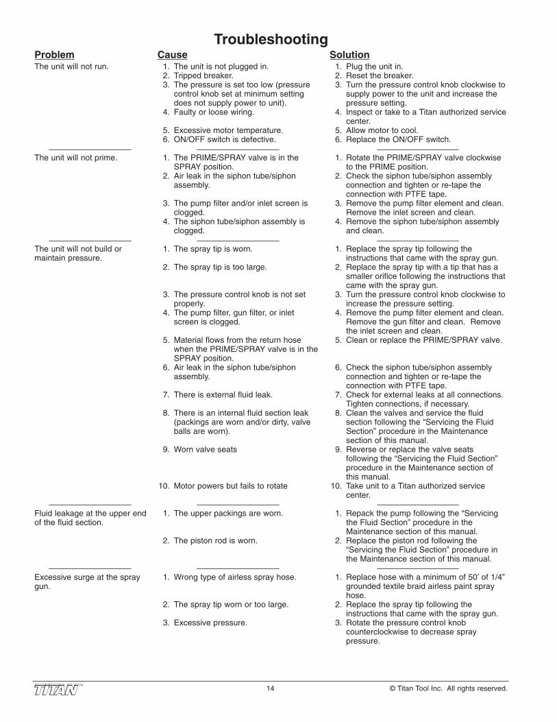
Solution1. Plug the unit in.2. Reset the breaker.3. Turn the pressure control knob clockwise to
supply power to the unit and increase thepressure setting.
4. Inspect or take to a Titan authorized servicecenter.
5. Allow motor to cool.6. Replace the ON/OFF switch.
1. Rotate the PRIME/SPRAY valve clockwiseto the PRIME position.
2. Check the siphon tube/siphon assemblyconnection and tighten or re-tape theconnection with PTFE tape.
3. Remove the pump filter element and clean.Remove the inlet screen and clean.
4. Remove the siphon tube/siphon assemblyand clean.
1. Replace the spray tip following theinstructions that came with the spray gun.
2. Replace the spray tip with a tip that has asmaller orifice following the instructions thatcame with the spray gun.
3. Turn the pressure control knob clockwise toincrease the pressure setting.
4. Remove the pump filter element and clean.Remove the gun filter and clean. Removethe inlet screen and clean.
5. Clean or replace the PRIME/SPRAY valve.
6. Check the siphon tube/siphon assemblyconnection and tighten or re-tape theconnection with PTFE tape.
7. Check for external leaks at all connections.Tighten connections, if necessary.
8. Clean the valves and service the fluidsection following the “Servicing the FluidSection” procedure in the Maintenancesection of this manual.
9. Reverse or replace the valve seatsfollowing the “Servicing the Fluid Section”procedure in the Maintenance section ofthis manual.
10. Take unit to a Titan authorized servicecenter.
1. Repack the pump following the “Servicingthe Fluid Section” procedure in theMaintenance section of this manual.
2. Replace the piston rod following the“Servicing the Fluid Section” procedure inthe Maintenance section of this manual.
1. Replace hose with a minimum of 50’ of 1/4”grounded textile braid airless paint sprayhose.
2. Replace the spray tip following theinstructions that came with the spray gun.
3. Rotate the pressure control knobcounterclockwise to decrease spraypressure.
Cause1. The unit is not plugged in.2. Tripped breaker.3. The pressure is set too low (pressure
control knob set at minimum settingdoes not supply power to unit).
4. Faulty or loose wiring.
5. Excessive motor temperature.6. ON/OFF switch is defective.
1. The PRIME/SPRAY valve is in theSPRAY position.
2. Air leak in the siphon tube/siphonassembly.
3. The pump filter and/or inlet screen isclogged.
4. The siphon tube/siphon assembly isclogged.
1. The spray tip is worn.
2. The spray tip is too large.
3. The pressure control knob is not setproperly.
4. The pump filter, gun filter, or inletscreen is clogged.
5. Material flows from the return hosewhen the PRIME/SPRAY valve is in theSPRAY position.
6. Air leak in the siphon tube/siphonassembly.
7. There is external fluid leak.
8. There is an internal fluid section leak(packings are worn and/or dirty, valveballs are worn).
9. Worn valve seats
10. Motor powers but fails to rotate
1. The upper packings are worn.
2. The piston rod is worn.
1. Wrong type of airless spray hose.
2. The spray tip worn or too large.
3. Excessive pressure.
ProblemThe unit will not run.
The unit will not prime.
The unit will not build ormaintain pressure.
Fluid leakage at the upper endof the fluid section.
Excessive surge at the spraygun.
Troubleshooting
14 © Titan Tool Inc. All rights reserved.
© Titan Tool Inc. All rights reserved. 15
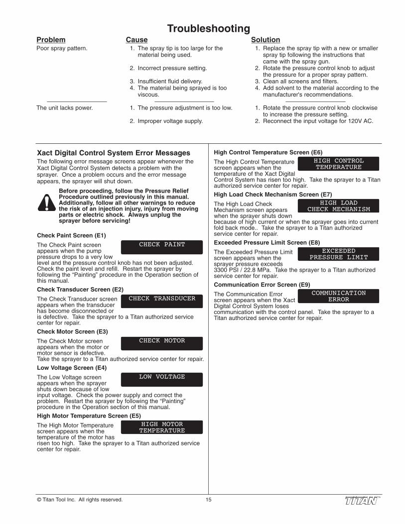
TroubleshootingProblemPoor spray pattern.
The unit lacks power.
Cause1. The spray tip is too large for the
material being used.
2. Incorrect pressure setting.
3. Insufficient fluid delivery.4. The material being sprayed is too
viscous.
1. The pressure adjustment is too low.
2. Improper voltage supply.
Solution1. Replace the spray tip with a new or smaller
spray tip following the instructions thatcame with the spray gun.
2. Rotate the pressure control knob to adjustthe pressure for a proper spray pattern.
3. Clean all screens and filters.4. Add solvent to the material according to the
manufacturer's recommendations.
1. Rotate the pressure control knob clockwiseto increase the pressure setting.
2. Reconnect the input voltage for 120V AC.
Xact Digital Control System Error MessagesThe following error message screens appear whenever theXact Digital Control System detects a problem with thesprayer. Once a problem occurs and the error messageappears, the sprayer will shut down.
Before proceeding, follow the Pressure ReliefProcedure outlined previously in this manual.Additionally, follow all other warnings to reducethe risk of an injection injury, injury from movingparts or electric shock. Always unplug thesprayer before servicing!
Check Paint Screen (E1)
The Check Paint screenappears when the pumppressure drops to a very lowlevel and the pressure control knob has not been adjusted.Check the paint level and refill. Restart the sprayer byfollowing the “Painting” procedure in the Operation section ofthis manual.
Check Transducer Screen (E2)
The Check Transducer screenappears when the transducerhas become disconnected oris defective. Take the sprayer to a Titan authorized servicecenter for repair.
Check Motor Screen (E3)
The Check Motor screenappears when the motor ormotor sensor is defective.Take the sprayer to a Titan authorized service center for repair.
Low Voltage Screen (E4)
The Low Voltage screenappears when the sprayershuts down because of lowinput voltage. Check the power supply and correct theproblem. Restart the sprayer by following the “Painting”procedure in the Operation section of this manual.
High Motor Temperature Screen (E5)
The High Motor Temperaturescreen appears when thetemperature of the motor hasrisen too high. Take the sprayer to a Titan authorized servicecenter for repair.
HIGH MOTORTEMPERATURE
LOW VOLTAGE
CHECK MOTOR
CHECK TRANSDUCER
CHECK PAINT
High Control Temperature Screen (E6)
The High Control Temperaturescreen appears when thetemperature of the Xact DigitalControl System has risen too high. Take the sprayer to a Titanauthorized service center for repair.
High Load Check Mechanism Screen (E7)
The High Load CheckMechanism screen appearswhen the sprayer shuts downbecause of high current or when the sprayer goes into currentfold back mode.. Take the sprayer to a Titan authorizedservice center for repair.
Exceeded Pressure Limit Screen (E8)
The Exceeded Pressure Limitscreen appears when thesprayer pressure exceeds3300 PSI / 22.8 MPa. Take the sprayer to a Titan authorizedservice center for repair.
Communication Error Screen (E9)
The Communication Errorscreen appears when the XactDigital Control System losescommunication with the control panel. Take the sprayer to aTitan authorized service center for repair.
COMMUNICATIONERROR
EXCEEDEDPRESSURE LIMIT
HIGH LOADCHECK MECHANISM
HIGH CONTROLTEMPERATURE

16 © Titan Tool Inc. Tous droits réservés.Français
Importantes consignes de sécurité • Lire toutes ces consignes
avant d’utiliser l’appareil. Garder ces consignes.
Indique une situation à risque, laquelle, si elle n'est pasévitée, peut entraîner des blessures graves, voire lamort.
Pour réduire les risques d’incendie ou d’explosion, dechoc électrique et de blessure, vous devez lire etcomprendre les directives figurant dans ce manuel.Familiarisez-vous avec les commandes et l’utilisationadéquate de l’équipement.
DANGER : INJECTION CUTANÉELe jet de haute pression produit par cet appareil peuttranspercer la peau et les tissus sous-jacents, causant desblessures graves pouvant entraîner l'amputation.NE PAS TRAITER CE TYPE DE BLESSURE COMME UNE SIMPLECOUPURE! Une amputation peut en résulter. ON DOITCONSULTER UN MÉDICIN SUR-LE-CHAMP. La pression maximale de ce pulvérisateur est d’environ 3 300 PSI /22,8 MPa.
MESURES PRÉVENTIVES :• Ne pas pointer le pistolet vers une partie du corps. • Ne pas pointer le pistolet vers une personne ou un animal; ne
pas pulvériser non plus de produit dessus.• NE JAMAIS mettre une partie du corps devant le jet de produit.
NE JAMAIS toucher les fuites du flexible de pulvérisation.• NE JAMAIS mettre la main, même gantée, devant le pistolet (les
gants n’offrent aucune protection contre les blessures parinjection).
• TOUJOURS verrouiller la détente, arrêter la pompe et relâcher toutela pression avant d’effectuer la maintenance de l’appareil ou de lelaisser sans surveillance, d’en nettoyer le protège-embout oul’embout, ou de remplacer ce dernier. La pression ne sera pasrelâchée par le simple arrêt du moteur; pour ce faire, on doit se servirdu bouton PRIME/SPRAY (se reporter à la section COMMENTLIBÉRER LA PRESSION, du présent manuel).
• TOUJOURS s'assurer que le protège-embout est en place avant depulvériser. Il est cependant à noter que, s’il assure une certaineprotection, ce dispositif joue surtout un rôle préventif.
• TOUJOURS retirer l’embout avant de vidanger ou de nettoyerl’appareil.
• TOUJOURS inspecter le flexible avant de commencer; celui-cipeut présenter des fuites attribuables à l’usure, à une flexionexcessibe ou à un traitement abusif, lesquelles fuites présententdes risques d’injection cutanée. Ne pas utiliser le flexible poursoulever ou tirer l’équipement.
• NE JAMAIS utiliser de pistolet sans verrou de détente et protège-doigts.
• Tous les accessoires (pistolets, embouts, rallonges, flexibles etc.)doivent pouvoir subir une pression nominale de 3 300 PSI / 22,8MPa ou plus.
• Ne laissez pas l’appareil sous tension ou sous pression quand vousvous en éloignez. Quand vous n’utilisez pas l’appareil, éteignez-leet libérez la pression conformément aux instructions COMMENTLIBÉRER LA PRESSION, du présent manuel.
• Vérifiez que toutes les connexions sont bien serrées avantd’utiliser l’appareil. Toute pièce qui n’est pas fixée solidementrisque d’être projetée violemment ou d’entraîner la fuite d’un jetde liquide à une pression extrêmement élevée, ce qui pourraitcauser des blessures graves.
• Verrouillez toujours la détente quand vous ne pulvérisez pas.Vérifiez que le verrou de la détente fonctionne correctement.
REMARQUE À L’INTENTION DES MÉDECINS : Les injections cutanées sont des lésions traumatiques; ilimporte donc de les traiter sans délai. On NE DOIT PAS retarderce traitement sous prétexte de vérifier la toxicité du produit encause, celle-ci n’étant conséquente que dans le cas d’injectiondirecte de certains produits dans le système sanguin. Il pourraits’avérer nécessaire de consulter un plasticien ou un spécialisteen chirurgie reconstructive de la main.
DANGER : ÉMANATIONS DANGEREUSESCertains produits (peintures, solvants, insecticides ou autres)peuvent être nocifs s’ils sont inhalés ou entrent en contactavec l’organisme. Les émanations de ces produits peuventprovoquer de graves nausées, évanouissements ouempoisonnements.MESURES PRÉVENTIVES :
• Se servir d’un masque ou d’un respirateur s’il y arisque d’inhalation (lire toutes les directives concernantces dispositifs afin de s’assurer qu’ils offrent laprotection requise).
• Porter des lunettes de protection.• Porter les vêtements de protection prescrits par le fabricant du
produit utilisé.
DANGER : EXPLOSION OU INCENDIELes émanations de certains produits peuvent exploser ous’enflammer, et risquent d’entraîner des dommages matérielsou de graves blessures.MESURES PRÉVENTIVES :
• S’assurer que l’aire de travail est dotée de moyens d’évacuationd’air vicié et d’introduction d’air frais pour éviter l’accumulation devapeurs inflammables. Les vapeurs dégagées par la peinture oules solvants peuvent provoquer une explosion ou s’enflammer.
• Ne pas pulvériser de produit dans un endroit clos.• Ne pas travailler près de sources d’ignition (décharges
électrostatiques ou étincelles provoquées par lebranchement/ débranchement d’appareils ou lacommutation d’interrupteurs, d'appareils électriques, flammesnues, veilleuses, objets chauds, etc.). La peinture ou le solvants’écoulant dans l’équipement peut générer de l’électricité statique.
• Ne pas fumer dans l’aire de travail.• L’aire de travail doit être munie d’un extincteur en bon état de
marche.• Prévoir un espace d’au moins 7.62 mètres entre la pompe et
l’objet à pulvériser s’ils sont dans la même pièce bien ventilée(rallonger le flexible au besoin). Les vapeurs inflammables étantsouvent plus lourdes que l’air, l’espace au-dessus du plancherdoit être particulièrement bien aéré. La pompe contient despièces qui produisent des arcs et émettent des étincelles pouvantenflammer les vapeurs.
• Les appareils et objets à l’intérieur ou à proximité de l’aire detravail doivent être adéquatement mis à la terre pour éviter lesdécharges électrostatiques.
• Veillez à ce que la zone soit propre et exempte de contenants depeinture ou de solvant, chiffons ou autres matériauxinflammables.
• Les flexibles dont on se sert doivent être conçus pour subir lespressions élevées et faits de matériaux conducteurs ou mis à laterre adéquatement; le pistolet sera mis à la terre par le biais deses raccords aux flexibles.
• Pour les appareils électriques — Le cordon d’alimentation doitêtre branché à un circuit trifilaire.
• L’appareil doit toujours être vidangé à basse pression, emboutretiré, dans un contenant métallique distinct. Tenir le pistoletcontre la paroi du contenant de manière à mettre ce dernier à laterre et à prévenir les décharges électrostatiques.
• Toujours respecter les mises en garde et les directives dufabricant des produits et solvants utilisés. On doit connaître lesproduits contenus dans les peintures et solvants qu'on pulvérise.Lire les fiches techniques santé-sécurité (FTSS) et les étiquettesdes contenants fournies avec les peintures et solvants. Suivresles consignes de sécurité du fabricant de peinture et de solvant.
• S’entourer de toutes les précautions possibles lorsqu’on utilisedes produits ayant un point d’éclair inférieur à 21°C (70°F). Lepoint d'éclair est la température à laquelle le liquide peut créersuffisamment de vapeurs et s'enflammer.
• Le plastique est générateur de décharges électrostatiques; nejamais en suspendre pour fermer une aire de travail ou en utiliseren guise de toile de protection lorsqu’on pulvérise un produitinflammable.
• Se servir de la pression la plus basse possible pour vidangerl’appareil.
• Ne pas pulvériser de produit sur la pompe.

© Titan Tool Inc. Tous droits réservés. 17 Français
Importantes consignes de sécurité • Lire toutes ces consignes
avant d’utiliser l’appareil. Garder ces consignes.
DANGER : EXPLOSION CAUSÉE PAR DES PRODUITSINCOMPATIBLES
Ce type d’explosion peut entraîner des dommages matérielsou des blessures graves.
MESURES PRÉVENTIVES :
• Ne pas utiliser de produits contenant du chlore ou du javellisant.
• Ne pas utiliser de solvants à base de halons comme l’eau dejavel, les agents antimoisissure, le chlorure de méthylène et letrichloroéthane-1-1-1, lesquels ne sont pas compatibles avecl’aluminium.
• Communiquer avec le fournisseur du produit concerné pour enconnaître la compatibilité avec l’aluminium.
DANGER : GÉNÉRALITÉSD’autres dangers peuvent entraîner des dommages matériels ou desblessures graves.
• Lire toutes les directives et consignes de sécurité avant d’utiliserl’appareil.
• Observer tous les codes locaux, provinciaux, d’état et nationauxrégissant la ventilation, la prévention des incendies et lefonctionnement de l’appareil.
• Aux États-Unis, le gouvernement a adopté des normes desécurité en vertu de l’Occupational Safety and Health Act (OSHA).Le cas échéant, on doit les consulter, notamment les parties 1910des normes générales et 1926 des normes de construction.
• N’utiliser que les pièces autorisées par le fabricant; les utilisateursqui choisiront d’utiliser des composants dont les caractéristiquestechniques et les exigences en matière de sécurité sontinférieures devront en assumer tous les risques et responsabilités.
• Tous les raccords, les tuyaux et les bouchons de remplissagedoivent être fixés solidement en place avant d’utiliser la pompede pulvérisation. Toute pièce qui n’est pas fixée solidementrisque d’être projetée violemment ou d’entraîner la fuite d’un jetde liquide à une pression extrêmement élevée, ce qui pourraitcauser des blessures graves.
• Avant chaque utilisation, examiner tous les flexibles afin deconfirmer l’absence de coupures, de fuites, d’abrasions ou derenflements. Vérifier également l’intégrité des raccords. Remplacersans délai les pièces qui semblent présenter des défectuosités. Nejamais tenter de réparer un flexible; remplacer ceux qui font défautpar des modèles haute pression, avec mise à la terre.
•. Ne faites pas de nouer avec le tuyau et ne le tordez pas trop. Letuyau à vide peut présenter des fuites suite à l’usure, les nouerou les mauvais traitements. Une fuite risque d’injecter du produitdans la peau.
•. N’exposez pas le tuyau à des températures ou des pressionssupérieures à celles spécifiées par le fabricant.
• Ne pas pulvériser à l’extérieur par grands vents.• Porter des vêtements aptes à protéger la peau et les cheveux du
produit utilisé.• Ne pas utiliser le pistolet ou ne pas pulvériser de produits en
présence d’enfants à proximité. Éloigner les enfants del’équipement en tout temps.
• Ne pas s'étirer ni ne travailler sur un support instable. Toujoursgarder les deux pieds au sol pour rester en équilibre.
• Se servir de la pression la plus basse possible pour vidangerl’appareil.
• Rester vigilant et faire attention à ce que l'on fait.• Ne pas se servir de l'équipement en cas de fatigue ou si vos
aptitudes sont affaiblies par la consommation de drogues ou deboissons alcoolisées.
• Pour les appareils électriques — Débranchez toujours le cordonélectrique de la prise avant de travailler sur l’équipement.
• N’utilisez pas le tuyau pour tirer ou soulever l’équipement.• Ne pas soulever par la poignée de chariot en chargeant ou en
déchargeant.
Instructions de mise à la terreCet appareil doit être mis à la terre. La mise à la terre réduitles risques d'électrocution lors d'un court-circuit en permettantau courant de s'écouler par le fil de mise à la terre. Cetappareil est muni d'un cordon électrique avec fil de mise à laterre ainsi que d'une fiche de terre. La fiche doit être branchéesur une prise installée correctement et mise à la terreconformément à la réglementation et aux codes en vigueur.
Le fait de ne pas brancher correctement lafiche trifilaire de l’appareil peut entraînerdes risques de choc électrique.
Si on doit réparer ou remplacer le cordon ou la fiche, ne pasraccorder le fil de terre à la borne des broches plates (lames)de cette dernière. Ce fil, normalement vert (avec ou sansrayures jaunes), doit être relié à la broche de terre.
Consulter un technicien ou un électricien qualifié à défaut decomprendre l’ensemble des présentes directives ou en casd’incertitude quant à la mise à terre de l’appareil. Ne pasmodifier la fiche de l’appareil; si elle ne s’adapte pas dans laprise voulue, faire remplacer cette dernière par un électricienqualifié.
IMPORTANT : Utiliser uniquement une rallonge à trois filsmunie d'une fiche de terre dans une prise secteur mise àla terre correspondant au type de fiche de l'appareil.S'assurer que votre rallonge est en bon état. Lorsquevous utilisez une rallonge, assurez-vous qu'elle soit d'uncalibre suffisant pour supporter l'intensité du courantrequise par l'appareil. Une rallonge trop mince entraîneune chute de tension, une diminution de l'intensité et unesurchauffe. Une rallonge de calibre 12 est recommandée.Si vous devez utiliser une rallonge à l’extérieur, celle-cidoit comprendre la marque W-A après la désignationindiquant le type de cordon. Par exemple, la désignationSJTW-A indique que le cordon est conçu pour être utiliséà l’extérieur.
Prise de terre
Goupille de mise à la terre
Couvercle du boîtier de prise de terre

18 © Titan Tool Inc. Todos los derechos reservados.Español
Información de seguridad importante • Lea toda la información de
seguridad antes de operar el equipo. Guarde estas instrucciones.
Indica una situación peligrosa que, de no evitarse,puede causar la muerte o lesiones graves.
Para reducir los riesgos de incendios, explosiones,descargas eléctricas o lesiones a las personas, lea yentienda todas las instrucciones incluidas en este man-ual. Familiarícese con los controles y el uso adecuadodel equipo.
PELIGRO: LESIÓN POR INYECCIÓNEl flujo de pintura a alta presión que produce este equipopuede perforar la piel y los tejidos subyacentes,ocasionando lesiones graves y posible amputación.CONSULTE A UN MÉDICO INMEDIATAMENTE.
¡NO TRATE LA LESIÓN POR INYECCIÓN COMO UNACORTADURA SIMPLE! La inyección puede ocasionaramputación. Consulte a un médico inmediatamente.La gama operativa máxima de la pistola es de 3300 PSI / 22.8 MPade presión del líquido.PREVENCIÓN:
• NUNCA apunte la pistola a ninguna parte del cuerpo.• No apunte con la pistola ni rocíe a cualquier persona o animal.• NUNCA deje que ninguna parte del cuerpo toque el flujo de
líquido. NO deje que el cuerpo toque una fuga de la manguera delíquido.
• NUNCA ponga la mano frente a la pistola. Los guantes noprotegen contra una lesión por inyección.
• SIEMPRE ponga el seguro del gatillo, apague la bomba y liberetoda la presión antes de dar servicio, limpiar la boquilla oprotección, cambiar la boquilla o dejar la pistola sin supervisión. Nose libera la presión al apagar el motor. Debe girarse la perillaPRIME/ SPRAY (CEBAR/ROCIAR) a PRIME (CEBAR) para aliviarla presión. Consulte el PROCEDIMIENTO PARA ALIVIAR LAPRESIÓN descrito en este manual.
• SIEMPRE mantenga la protección de la boquilla en su sitio alrociar. La protección de la boquilla sirve principalmente dedispositivo de advertencia.
• SIEMPRE retire la boquilla rociadora antes de enjuagar o limpiarel sistema.
• La manguera de pintura puede presentar fugas por desgaste,dobleces y maltrato. La fuga puede inyectar material traspasandola piel. Inspeccione la manguera antes de cada uso. No usemangueras para levantar o tirar del equipo.
• NUNCA use una pistola rociadora sin contar con el seguro y laprotección del gatillo.
• Todos los accesorios deben tener capacidades nominales de3300 PSI / 22.8 MPa como mínimo. Esto incluye las boquillasrociadoras, pistolas, extensiones y manguera.
• No deje el aparato con corriente ni con presión cuando nadie estépendiente de ella. Cuando no utilice el aparato, apáguelo y liberela presión siguiendo las instrucciones del PROCEDIMIENTOPARA ALIVIAR LA PRESIÓN descrito en este manual.
• Antes de utilizar el aparato, verifique que todas las conexionesson seguras. Las partes no aseguradas pueden ser expulsadascon gran fuerza o filtrar fluido a alta presión y provocar lesionesseveras.
• Ponga siempre el seguro del gatillo cuando no esté pulverizando.Verifique que el seguro del gatillo funciona correctamente.
NOTA PARA EL MÉDICO: La inyección a través de la piel es unalesión traumática. Es importante tratar la lesión tan pronto seaposible. NO retrase el tratamiento para investigar la toxicidad. Latoxicidad es un factor a considerar con ciertos revestimientosinyectados directamente en la corriente sanguínea. Puede seraconsejable consultar con un cirujano plástico o un cirujanoespecialista en reconstrucción de las manos.
PELIGRO: VAPORES PELIGROSOS
Las pinturas, solventes, insecticidas y demás materialespueden ser nocivos si se inhalan o toman contacto con elcuerpo. Los vapores pueden causar náuseas graves,desmayos o envenamiento.
PREVENCIÓN:• Use un respirador o mascarilla si pueden inhalarse los
vapores. Lea todas las instrucciones suministradascon la mascarilla para revisar que brinde la protecciónnecesaria.
• Use lentes protectores.• Use ropa protectora según lo indique el fabricante del
revestimiento.
PELIGRO: EXPLOSIÓN O INCENDIO
Los vapores de solventes y pinturas pueden explotar oinflamarse. Pueden producirse daños materiales, lesionesgraves o ambos.PREVENCIÓN:
• Cuente con escape y entrada de aire fresco para mantener elaire dentro de la zona de aplicación sin acumulaciones devapores inflamables. Los gases producidos por solventes opinturas pueden causar explosiones o incendios.
• No rocíe en lugares cerrados.• Evite todas las fuentes de ignición como las chispas de
electricidad estática, las llamas expuestas, applianceselectricidad, las luces piloto y los objetos calientes. La conexión odesconexión de cables eléctricos o interruptores de luzoperativos puede producir chispas. Si la pintura o el solventefluyen por el equipo se puede generar electricidad estática.
• No fume en el área de aplicación.• Debe haber un extintor de incendios en buen estado.• Coloque la bomba de pintura a un mínimo de 7.62 meters (25
pies) del objeto a pintar dentro de un área bien ventilada (añadamás manguera si es necesario). Los vapores inflamables songeneralmente más pesados que el aire. El área debe estarsumamente bien ventilada.
• El equipo y los objetos dentro y alrededor del área a pintar debenestar debidamente conectados a tierra para evitar las chispas deestática.
• Mantenga el área limpia y libre de contenedores de pintura osolvente, trapos y otros materiales inflamables.
• Use solamente una manguera conductora o conectada a tierrapara líquidos a alta presión. La pistola debe conectarse a tierra através de las conexiones de la manguera.
• Para las aparatos eléctricas — Debe conectarse el cableeléctrico a un circuito a tierra.
• Siempre enjuague la unidad dentro de un recipiente metálicoseparado, con la bomba a baja presión y habiendo sacado laboquilla rociadora. Sostenga la pistola firmemente contra elcostado del recipiente para conectar a tierra el mismo y evitarchispas de estática.
• Siga las advertencias e instrucciones del fabricante del material ydel solvente. Conozca los contenidos de las pinturas y lossolventes con los que rocía. Lea todas las Hojas de Datos sobreSeguridad de Materiales (MSDS) y las etiquetas del contenedorprovistas con las pinturas y los solventes. Siga las instruccionesde seguridad del fabricante de pinturas o solventes.
• Tenga muchísmo cuidado al usar materiales cuyo punto deignición sea inferior a 70°F (21°C). El punto de inflamación es latemperatura a la que un fluido puede producir vapores suficientespara encenderse.
• El plástico puede causar chispas de estática. Nunca cuelgueplásticos para cerrar una zona a pintar. No use mantas plásticasal aplicar materiales inflamables.
• Use la presión más baja posible para enjuagar el equipo.• No rocíe el ensamblaje de la bomba.

© Titan Tool Inc. Todos los derechos reservados. 19 Español
Información de seguridad importante • Lea toda la información de
seguridad antes de operar el equipo. Guarde estas instrucciones.
PELIGRO: POSIBLE EXPLOSIÓN DEBIDO AMATERIALES INCOMPATIBLES
Causará daños materiales o lesiones graves.
PREVENCIÓN:
• No use materiales que contengan blanqueador o cloro.
• No use solventes de hidrocarburos halogenados comoblanqueador, mohocida, cloruro de metileno y 1,1,1 tricloroetano.No son compatibles con el aluminio.
• Diríjase al proveedor de revestimientos para obtener los datos decompatibilidad del material con el aluminio.
PELIGRO: GENERAL
Puede causar daños materiales o lesiones graves.
PREVENCIÓN:
• Lea todas las instrucciones y las precauciones de seguridadantes de operar el equipo.
• Siga todos los códigos locales, estatales y nacionalescorrespondientes que rijan la ventilación, prevención deincendios y operación.
• Se han adoptado las normas de seguridad del Gobierno de losEstados Unidos según la Ley de seguridad ocupacional y salud(Occupational Safety and Health Act, OSHA). Deben consultarseestas normas, particularmente el apartado 1910 de las Normasgenerales y el apartado 1926 de las Normas de construcción.
• Utilice solamente componentes autorizados por el fabricante. Elusuario asume todo riesgo y responsabilidad al utilizarcomponentes que no cumplan con las especificaciones mínimasy requisitos de seguridad del fabricante de la bomba.
• Todos los acopladores, las mangueras y las tapas de los filtrosdeben estar asegurados antes de operar la bomba de rocío. Laspartes no aseguradas pueden ser expulsadas con gran fuerza ofiltrar fluido a alta presión y provocar lesiones severas.
• Antes de cada uso, revise todas las mangueras en busca decortes, fugas, abrasión o hinchazón de la cubierta. Revise si haydaños o movimiento de los acoplamiento. Cambieinmediatamente la manguera si existe alguna de estascondiciones. Nunca repare una manguera de pintura. Cámbielapor otra manguera conectada a tierra apta para alta presión.
• No retuerza ni doble la manguera en exceso. En la mangueraairless pueden aparecer fugas a causa del desgaste, deretorcimientos o de un mal uso. Una fuga puede inyectar materialen la piel.
• No exponga la manguera a temperaturas o presiones quesuperen las especificadas por el fabricante.
• No pinte en exteriores en días con viento.
• Use ropa que mantenga la pintura alejada de la piel y el cabello.
• No lo opere ni rocíe cerca de los niños. Mantenga a los niñosalejados del equipo en todo momento.
• No se asome ni se pare sobre soportes inestables. Mantengasiempre la posición firme y el equilibrio efectivos.
• Use la presión más baja posible para enjuagar el equipo.
• Manténgase alerta y mire lo que hace.
• No utilice la unidad cuando se encuentre cansado o bajo lainfluencia de las drogas o el alcohol.
• Para las aparatos eléctricas — Desenchufe siempre el cableantes de trabajar en el equipo.
• No utilice la manguera como elemento de fuerza para tirar delequipo o levantarlo.
• No levantar por la manija del carro al cargar o descargando.
Instrucciones para conectar a tierraEste producto se debe conectar a tierra. En caso de queocurra un corto circuito, la conexión a tierra reduce el riesgode choque eléctrico al proporcionar un alambre de escapepara la corriente eléctrica. Este producto está equipado conun cable que tiene un alambre de conexión a tierra con unenchufe de conexión a tierra apropiado. El enchufe se debeenchufar en una toma de corriente que se haya instalado yconectado a tierra debidamente, de acuerdo con todos loscódigos y estatutos locales.
La instalación incorrecta del enchufe atierra puede ocasionar un riesgo dechoque eléctrico.
Si es necesario reparar o cambiar el cable o el enchufe, noconecte el cable verde a tierra a ninguno de las terminales deespiga plana. El cable con aislamiento de color verde porfuera con o sin rayas amarillas es el alambre a tierra y debeconectarse a la espiga a tierra.
Consulte a un electricista o técnico de servicio capacitado silas instrucciones para la conexión a tierra no se entiendenclaramente o si tiene dudas en cuanto a que el producto estédebidamente conectado a tierra. No modifique el enchufe quese incluye. Si el enchufe no encaja en el receptáculo, pida aun electricistas capacitado que instale un receptáculoadecuado.
IMPORTANTE: Use solamente extensiones trifilares quetengan un enchufe de conexión a tierra de 3 hojas y unreceptáculo de triple ranura que acepte el enchufe delproducto. Asegúrese de que su extensión esté en buenascondiciones. Cuando use una extensión, asegúrese deusar una que sea lo suficientemente resistente como parasoportar la corriente que descargue su producto. Un cablede un tamaño menor causará una caída de voltage en lalínea que dará como resultado una pérdida de energía y unsobrecalenta|ôento. Se recomienda usar un cable decalibre 12. Si se utiliza un cable de extensión en el exterior,tiene que estar marcado con el sufijo W-A después de ladesignación del tipo de cable. Por ejemplo, SJTW-A paraindicar que el cable es apropiado para uso en exteriores.
Tomacorriente aterrado
Terminal de tierra
Tapa de la caja del tomacorriente aterrado
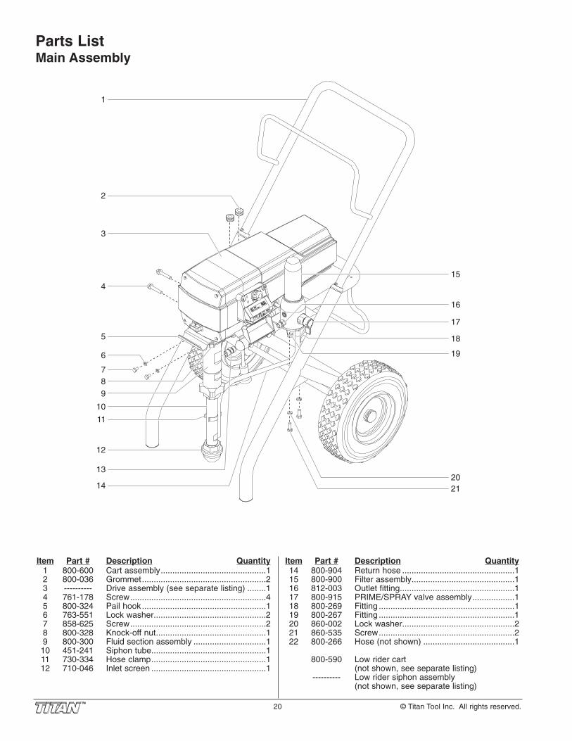
20 © Titan Tool Inc. All rights reserved.
Parts List Main Assembly
1
2
6
7
3
13
14
5
9
8
10
11
12
415
16
18
19
2021
17
Item Part # Description Quantity1 800-600 Cart assembly.............................................12 800-036 Grommet.....................................................23 ---------- Drive assembly (see separate listing) ........14 761-178 Screw..........................................................45 800-324 Pail hook.....................................................16 763-551 Lock washer................................................27 858-625 Screw..........................................................28 800-328 Knock-off nut...............................................19 800-300 Fluid section assembly ...............................110 451-241 Siphon tube.................................................111 730-334 Hose clamp.................................................112 710-046 Inlet screen .................................................1
Item Part # Description Quantity14 800-904 Return hose ................................................115 800-900 Filter assembly............................................116 812-003 Outlet fitting.................................................117 800-915 PRIME/SPRAY valve assembly..................118 800-269 Fitting ..........................................................119 800-267 Fitting ..........................................................120 860-002 Lock washer................................................221 860-535 Screw..........................................................222 800-266 Hose (not shown) .......................................1
800-590 Low rider cart(not shown, see separate listing)
---------- Low rider siphon assembly(not shown, see separate listing)

© Titan Tool Inc. All rights reserved. 21
Item Part # Description Quantity1 800-078 Electronic cover ..........................................12 800-205 Screw..........................................................33 800-984 Motor assembly ..........................................14 800-525 Housing gasket ...........................................15 800-541 Shroud gasket.............................................16 800-261 1st stage gear assembly.............................17 800-262 2nd stage gear asembly .............................18 800-260 Front gearbox assembly)............................19 704-380 ON/OFF switch ...........................................110 800-510 Slider assembly ..........................................111 800-253 Slider housing.............................................112 700-283 Screw..........................................................413 800-406 Front cover..................................................114 800-284 Screw..........................................................415 800-382 Retaining ring..............................................116 800-753 Connecting pin............................................117 800-229 Ground screw .............................................118 779-568 Mounting plate ............................................119 800-077 Grommet.....................................................120 800-076 Screw..........................................................121 800-688 Control panel ..............................................122 704-486 Screw..........................................................423 704-488 Pressure control knob.................................124 704-469 Xact Digital Control System assembly
(optional).....................................................1
Item Part # Description Quantity25 704-467 Xact Digital Control system cover (optional) .126 704-487 Screw..........................................................227 779-567 Strain relief..................................................128 704-553 Power cord..................................................129 700-287 Screw..........................................................330 763-551 Lock washer................................................331 800-658 Electronic control assembly........................132 800-215 Fan shroud..................................................133 800-294 Fan assembly .............................................134 800-435 Baffle assembly ..........................................135 800-283 Screw..........................................................436 800-405 Motor shroud...............................................137 704-599 Dust cover (for sprayers without Xact
Digital Control System)...............................138 704-473 Control panel cover (for sprayers without
Xact Digital Control System).......................139 704-594 Surge suppressor (not shown) ...................140 800-929 Fuse, 15A (not shown)................................141 770-781 Electronic control mounting screw
(not shown) .................................................442 765-060 Electronic control lock washer (not shown)..443 770-596 Electronic control washer (not shown) .......4
NOTE: All electrical work should be performed by aTitan authorized service center.
Drive Assembly
29
1
3
4
5
6
7
8
10
9
11
12
13
15
16
14
2
35
36
1817
19
2021
22
24
25
26
27
28
23
30
31
33
32
34
37
38

22 © Titan Tool Inc. All rights reserved.
Fluid Section Assembly (P/N 800-300)
1
5
10
13
17
18
1920
7
8
21
7
8
9
11
12
14
15
16
6
3
2
4
Install lower packing with the side that has the o-ring
closest to the top of the packing facing up.
Install upper packing with raised lip facing down.
Raised Lip
22
Closer
Top
NOTE: When repacking the fluid section, makesure the raised lip on the bottom of thelower packing is fully outside the packingaround the piston rod after insertion ofthe piston rod.

© Titan Tool Inc. All rights reserved. 23
Item Part # Description Quantity1 800-325 Upper seal retainer .....................................12 800-327 Spacer ........................................................13 800-248 Upper packing assembly ............................14 800-351 Upper housing ............................................15 800-250 Lower packing assembly ............................16 800-354 Wear ring ....................................................17 800-332 O-ring, Viton................................................28 800-333 Back-up ring, PTFE ....................................29 800-352 Lower housing ............................................110 800-246 Piston rod....................................................111 800-348 Outlet valve seal .........................................112 800-244 Outlet valve cage........................................113 800-247 Outlet valve ball ..........................................1
Item Part # Description Quantity14 800-245 Washer, nylon .............................................115 800-243 Outlet valve seat.........................................116 800-336 Outlet valve retainer ...................................117 800-322 Foot valve cage ..........................................118 800-242 Foot valve ball ............................................119 800-241 Foot valve seat ...........................................120 762-058 O-ring..........................................................121 800-305 Foot valve housing .....................................122 800-365 Piston assembly (includes items 10–16) ....1
800-273 Repacking kit (includes items 2, 3, 5–8, 11, 13, 14, 18, and 20)
800-359 Lower packing insertion tool
High Rider Cart (P/N 800-600)
Item Part # Description Quantity1 800-280 Handle
(includes items 2–5, 10, and 11) ................12 590-508 Roll pin........................................................23 590-507 Snap button ................................................24 590-504 Sleeve.........................................................25 590-506 Washer........................................................26 800-011 Spacer ........................................................27 710-199 Plug.............................................................28 800-279 Cart (includes items 7 and 9) .....................19 335-018 Plug.............................................................210 856-002 Washer........................................................411 856-921 Screw..........................................................412 800-007 Axle.............................................................113 670-109 Wheel..........................................................214 870-004 Washer........................................................215 800-019 Cap .............................................................2
1
3
4
2
5
6
7
9
8
10
11
12
14
15
13
Filter Assembly (P/N 800-900)
Item Part # Description Quantity1 800-905 Filter body...................................................12 800-252 Filter spring .................................................13 730-067 Filter, 60 mesh ............................................14 702-251 Filter spring adapter....................................15 757-105 Core spring .................................................16 800-906 O-ring, PTFE ..............................................17 800-908 Plug, 3/8” ....................................................18 800-901 Filter housing ..............................................19 800-915 PRIME/SPRAY valve assembly..................110 800-907 Plug, 1/4” ....................................................111 800-437 Transducer..................................................1
6
7
8
9
10
2
1
3
4
5
11

24 © Titan Tool Inc. All rights reserved.
Low Rider Cart (P/N 800-590)1
2
3
4
5
6
7
8
9
10
11
12
13
16
15
14
Item Part # Description Quantity1 590-506 Washer........................................................22 590-504 Sleeve.........................................................23 590-507 Snap button ................................................24 800-113 Handle assembly
(includes items 1–3 and 5–7) .....................15 590-508 Roll pin........................................................26 856-921 Screw..........................................................47 856-002 Washer........................................................48 700-674 Plug.............................................................2
Item Part # Description Quantity9 704-188 Screw..........................................................1
10 335-018 Plug.............................................................211 700-1041 Drip cup ......................................................112 704-291 Roll pin........................................................213 800-109 Wheel spacer..............................................214 800-593 Wheel..........................................................215 800-111 Cap .............................................................216 800-112 Cart weldment (includes items 8 and 10)...1
Low Rider Siphon Assembly
1
2
3
4
5
6
Item Part # Description Quantity1 800-903 Return hose ................................................12 710-203 Siphon tube.................................................13 710-195 Swivel .........................................................14 710-046 Inlet screen .................................................15 730-334 Clamp .........................................................16 710-081 Siphon tube adapter ...................................17 700-742 Tie wrap (not shown) ..................................3
710-204 Siphon tube assembly (includes items 2–6) ...................................1
LabelsPart # Description
313-1708 1140ix logo label313-2641 “Titan” front label313-1673 Warning label (injection/explosion)313-1847 Shock hazard label313-2395 Infinity logo label313-2324 X-Lock label313-2327 Xact Digital Control System label313-2328 Xact Instruction label313-2430 Transducer warning label

© Titan Tool Inc. All rights reserved. 25
Transducer
Electronic Control Assembly
Potentiometer
Motor
Plu
g
Control Panel Board
Surge Suppressor
Fuse
SwitchGround
WHITE
BLACK
WHITE
AC-Motor
AC-NeutAC-Line
AC-Motor
J16 J9J2J1
J12 J7
WH
ITE
BLA
CK
GREEN
Electrical Schematic
NOTE: All electrical work should be performedby a Titan authorized service center.
PRIME/SPRAY Valve Assembly(P/N 800-915)
Item Part # Description Quantity1 800-915 PRIME/SPRAY valve assembly..................12 700-537 Gasket ........................................................13 222-012 O-ring, PTFE ..............................................14 221-012 O-ring, Viton................................................15 700-721 Valve stem o-ring, Viton..............................1
700-897 Valve stem o-ring, PTFE (optional)6 700-252 Cam base ...................................................17 700-759 Groove pin ..................................................18 700-697 Valve handle ...............................................1
NOTE: When using “hot” solvents, replace Vitonvalve stem o-ring (item 5) with optional PTFEvalve stem o-ring (P/N 700-897). Install usingo-ring replacement tool (P/N 700-890).
1 2
3
4
5
6
7
8

26 © Titan Tool Inc. All rights reserved.
AccessoriesAirless Tip SelectionTips are selected by the orifice size and fan width. The properselection is determined by the fan width required for a specificjob and by the orifice size that will supply the desired amountof fluid and accomplish proper atomization.For light viscosity fluids, smaller orifice tips generally aredesired. For heavier viscosity materials, larger orifice tips arepreferred. Please refer to the chart below.
The following chart indicates the most common sizes and theappropriate materials to be sprayed.
Fan widths measuring 8" to 12" (20 to 30 cm) are preferredbecause they offer more control while spraying and are lesslikely to plug.
Liquid Shield PlusCleans and protects spray systemsagainst rust, corrosion and prematurewear. Now with -25º anti-freezeprotection.
Part # Description314-483...........4 ounce bottle314-482...........1 quart bottle
Piston LubeSpecially formulated to prevent materialsfrom adhering to the piston rod, whichbecomes abrasive to the upper seals.Piston Lube will break down any materialthat may accumulate in the oil cup andkeep it from drying.
Part # Description314-481...........4 ounce bottle314-480...........8 ounce bottle
LX-80II Airless Gun• 3600 PSI• All metal construction• In-handle filter• High pressure swivelPart No. Description580-100...........LX-80II — 4 Finger Gun581-085...........LX-80II — 2 Finger Gun580-050...........LX-80II — 4 Finger GTH Kit581-150...........LX-80II — 2 Finger GTH Kit
S-3 Stainless Steel Airless Gun• 3900 PSI• Stainless Steel fluid passages• High Pressure Swivel• In-handle filter• 4-finger trigger pullPart No. Description550-250...........S-3 — 4 Finger Gun
Tip Size Spray Material Filter Type
.011 – .013 Lacquers and stains 100 mesh filter
.015 – .019 Oil and latex 60 mesh filter
.021 – .026 Heavy bodied latex and blockfillers 30 mesh filter
NOTE: Do not exceed the sprayer's recommendedmaximum tip size.
Synergy Fine Finish Tips• Perfect for all fine finish work• Ideal for lacquers, stain, enamels, urethane, and clear top
coats• Increases standard tip life up to 80%• Delivers up to a 27% finer atomization at lower pressures• Increases transfer efficiency resulting in less oversprayPart No. Description671-XXX ..........Synergy Fine Finish Tips
WideSpray Reversible Tips• Designed for high production applications• Increase production up to 100%• WideSpray will save time and make you more moneyPart No. Description
661-XXXX .........WideSpray Reversible Tips
I-Remote Universal Remote Control System• Operates your sprayer from over 100 feet away• Works through walls, trees and other obstacles• Increase or decrease the pressure of the sprayer without
climbing down off the ladderPart No. Description800-690...........I-Remote Control System 800-691...........I-Remote Control Only800-692...........I-Remote Receiver Only
Xact Digital Control SystemThe Xact Digital Control System is an optional add-on thatincreases the functionality of the sprayer. It consists of adisplay and four function keys. The display shows the usermenu features that enable the user to become moreproductive and profitable
• X-Lock Security Features (Individualized Codes)• Pressure Reading — Set Pressure and Working Pressure• User Preset Keys• Total Gallons Sprayed• Resetable Job Gallon Counter• Total On Time and Run Time• Resetable On Time and Run Time• Programmable Service Time (Hour Meter)• Advanced DiagnosticsPart No. Description704-555...........Xact Digital Control System with Cover
MiscellaneousPart No. Description490-012...........Hose Coupling, 1/4" x 1/4"730-397...........High Pressure Fl. Gauge314-171...........Lubriplate, 14 ounce individual314-172...........Lubriplate, 6 lb. can
700-1037..........Electrostatic discharge (ESD) wrist strap

© Titan Tool Inc. All rights reserved. 27
Notes/Nota

28 © Titan Tool Inc. All rights reserved.
United States Sales & Service
1770 Fernbrook LaneMinneapolis, MN 55447
www.titantool.com
200 Trowers Road, Unit 7BWoodbridge, Ontario L4L 5Z8
Tech Service/Order Entry:Fax (Order Entry):
Fax (Tech Service):
1-800-526-53621-800-528-48261-800-525-9501
Phone:Fax:
1-800-565-86651-800-856-8496
Canadian Branch
1770 Fernbrook LaneMinneapolis, MN 55447
Phone:Fax:
1-201-337-12401-201-405-7449
International
Material Safety Data Sheets (MSDS) are available on Titan’s website or by calling Customer Service.
Titan Tool, Inc., (“Titan”) warrants that at the time of delivery to the original purchaser for use (“End User”), the equipmentcovered by this warranty is free from defects in material and workmanship. With the exception of any special, limited, orextended warranty published by Titan, Titan’s obligation under this warranty is limited to replacing or repairing without chargethose parts which, to Titan’s reasonable satisfaction, are shown to be defective within twelve (12) months after sale to the EndUser. This warranty applies only when the unit is installed and operated in accordance with the recommendations andinstructions of Titan.
This warranty does not apply in the case of damage or wear caused by abrasion, corrosion or misuse, negligence, accident,faulty installation, substitution of non-Titan component parts, or tampering with the unit in a manner to impair normal operation.
Defective parts are to be returned to an authorized Titan sales/service outlet. All transportation charges, including return to thefactory, if necessary, are to be borne and prepaid by the End User. Repaired or replaced equipment will be returned to the EndUser transportation prepaid.
THERE IS NO OTHER EXPRESS WARRANTY. TITAN HEREBY DISCLAIMS ANY AND ALL IMPLIED WARRANTIESINCLUDING, BUT NOT LIMITED TO, THOSE OF MERCHANTABILITY AND FITNESS FOR A PARTICULAR PURPOSE, TOTHE EXTENT PERMITTED BY LAW. THE DURATION OF ANY IMPLIED WARRANTIES WHICH CANNOT BE DISCLAIMED ISLIMITED TO THE TIME PERIOD SPECIFIED IN THE EXPRESS WARRANTY. IN NO CASE SHALL TITAN LIABILITY EXCEEDTHE AMOUNT OF THE PURCHASE PRICE. LIABILITY FOR CONSEQUENTIAL, INCIDENTAL OR SPECIAL DAMAGESUNDER ANY AND ALL WARRANTIES IS EXCLUDED TO THE EXTENT PERMITTED BY LAW.
TITAN MAKES NO WARRANTY AND DISCLAIMS ALL IMPLIED WARRANTIES OF MERCHANTABILITY AND FITNESS FOR APARTICULAR PURPOSE WITH RESPECT TO ACCESSORIES, EQUIPMENT, MATERIALS OR COMPONENTS SOLD BUT NOTMANUFACTURED BY TITAN. THOSE ITEMS SOLD, BUT NOT MANUFACTURED BY TITAN (SUCH AS GAS ENGINES,SWITCHES, HOSES, ETC.) ARE SUBJECT TO THE WARRANTY, IF ANY, OF THEIR MANUFACTURER. TITAN WILL PROVIDETHE PURCHASER WITH REASONABLE ASSISTANCE IN MAKING ANY CLAIM FOR BREACH OF THESE WARRANTIES.
Warranty
PatentsThese products are covered by one or more of the following U.S. patents:
6,031,352 5,848,566 5,769,321 5,725,364 5,671,656 5,435,697 5,228,8425,346,037 5,252,210 5,217,238 5,192,425 4,908,538 4,768,929 4,744,571D384,676 6,179,222 5,934,883 4,723,892


![ASADS Ethics for the Substance Abuse Professional (Smith) Only]](https://static.fdocuments.net/doc/165x107/54fe3a374a7959f4248b4d91/asads-ethics-for-the-substance-abuse-professional-smith-only.jpg)


