
for Process Automation - P-NET · PDF file3 P-NET in General The P-NET Fieldbus is designed to...
20
Produced by: The International P-NET User Organization 590 004 02 for Process Automation P-NET® is a registered trade mark. ©Copyright 1996 by International P-NET User Organization. All rights reserved. P-NET The Fieldbus P-NET - the European Fieldbus Standard EN 50170, Volume 1
Transcript of for Process Automation - P-NET · PDF file3 P-NET in General The P-NET Fieldbus is designed to...

Produced by: The International P-NET User Organization 590 004 02
for Process Automation
P-NET® is a registered trade mark.
©Copyright 1996 by International P-NET User Organization. All rights reserved.
P-NETThe Fieldbus
P-NET- the European Fieldbus Standard
EN 50170, Volume 1

2
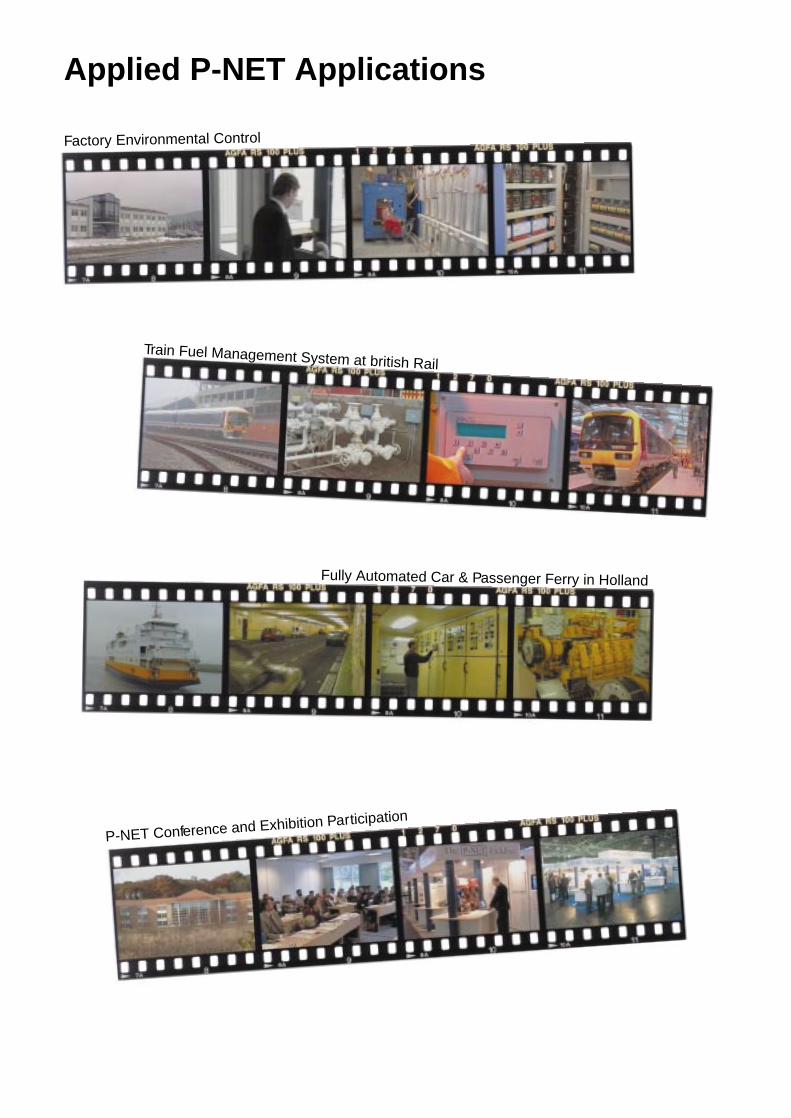
Applied P-NET Applications
Textile Production Plant
Test Line at Bosch-Siemens Dish Washing Machine Factory
Applied Building Automation
Animal Feeding & Climatic Control

3
P-NET in GeneralThe P-NET Fieldbus is designed to connect distributed process components likeprocess computers, intelligent sensors, actuators, I/O modules, field and centralcontrollers, PLC’s etc., via a common two wire cable, as shown in fig. 1.
This replaces traditional wiring, where a great many cables are involved.
Process data (e.g. measurement values, valve signals) are transmitted digitally. P-NET is also used for data collection, for configuration of nodes/sensors, and for down-loading of programs.
Apart from the usual measurement values and status data, the bus provides abidirectional exchange of additional information concerning limit values, actuatorpositioning and feedback signals, fault signals and internal system data.
P-NET can be used to download parameters and programs to modules, which thencontrol the process. The use of intelligent P-NET sensors and actuators also offersmuch better diagnostic features than with traditional wiring.
Further comparisons with conventional wiring, show that the incorporation of P-NEToffers proved advantages when applied to industrial processes.
The result is a simplification of planning and installation, a reduction in the amountand cost of cabling, a reduction in installation and maintenance costs, a reduction ininstallation errors, leading to a more straightforward future expansion of applications.Instant information about field device faults, and faults in the cable, can be detectedautomatically by the network protocol.
P-NET applications are characterised by their low cost for a small system. The costrises linearly with the size of a system.
P-NET is as well suited for small plants, as for large plants having many controllers,sensors, and interface modules. In addition, any such system is always ready for anynecessary expansion.
Figure 1: P-NET Fieldbus with distributed process components.

4
The History of P-NETP-NET was conceived in 1983. The first product using this multi-master Fieldbus waslaunched in 1984.
The multi-network and multi-port functions were added to the protocol specificationin 1986. The first operational P-NET multi-port product was produced in 1987.
The P-NET standard became an open and complete standard in 1989, for adoptionworldwide.
Due to an increasing interest in P-NET, the International P-NET User Organizationwas formed a year later.
Application AreasThe P-NET Fieldbus has been used for many years, and more than 5000 applicationsare now in operation worldwide. Applications range from simple installations with afew I/O points, to very large and complex installations using many thousand I/O points.
P-NET applications are found in the process industry environment and in discreteparts manufacturing plants.
The following typical examples show where P-NET is currently installed and running:Dairies, breweries, environmental control in agriculture, animal feeding systems,asphalt and concrete production, textile industry, milk/oil/fertilizer distribution trucks,quality control systems, power plants, solar power plants, plastic moulding, ship enginecontrol, tank management/alarm systems (approved by German Lloyd, Bureau Veritas,Norske Veritas, Lloyds Register of Shipping), data acquisition, water supply, buildingautomation, fuel management systems, (approved as legal for trade by PTB, NMI,NWML, ...).
The typical P-NET application requires response times measured in ms, and a buslength up to one km or more. There are other types of applications which demand aresponse time measured in ìs. For these applications P-NET is not appropriate.
Principles of P-NETThe electrical specification of P-NET is based on the RS485 standard using a shieldedtwisted pair cable. This allows a cable length of up to 1200 m without repeaters. Datais sent as an asynchronous transmission in NRZ code.
P-NET interfaces are galvanically isolated, and up to 125 devices per bus segmentcan be connected, due to a special clamp circuit, and again without the use ofrepeaters.
P-NET is a very efficient Fieldbus protocol, in that it can handle up to 300 confirmeddata transactions per second, from 300 independent addresses.
Data can be transferred in the form of fully processed values (floating point), such astemperature, pressure, current, voltage etc., or as blocks of 32 independent binarysignals, indicating valve states, switch positions etc.
This results in a performance of up to 9,600 binary signals per second being accessedfrom anywhere within the complete system.

5
This high rate of fully acknowledged data transmissions can be achieved, because P-NET slaves handle the processing of data and the reception or transmission of frames,in parallel. The processing of a request by the slave is initiated as soon as the firstdata bytes arrive. This is in contrast to dedicated chip solutions, where the entireframe arrives before processing begins. In this way, the standard P-NET data rate of76,800 bit/s, is not a limiting factor in performance.
The performance can be compared with systems using data rates up to 500,000 bit/s. See a detailed description on page 17 “P-NET Compared with Dedicated FieldbusChip Solutions”.
P-NET is a multi-master bus, which can accept up to 32 masters per bus segment. Allcommunication is based on the principle, where a Master sends a request, and theaddressed Slave returns an immediate response. Requests can be of a read or writetype. Masters and slaves are shown in fig 2.
Data transferred on the bus can be of a simple or complex type, to satisfy therequirements of measurement and control. Simple types include boolean, byte, char,word, integer, long integer, real, long real and timer. Complex types include array,string, record and buffer.
The data format is a part of the P-NET standard.
The right to access the bus, is transferred from one P-NET master to another, bymeans of a token. P-NET uses a method called “virtual token passing”, which doesnot require messages to be sent over the bus.
When a master has finished bus access, the token is automatically passed on to thenext master, by a cyclic mechanism based on time. The method used in P-NET differsfrom that used in other multi-master systems.
Other busses such as Profibus for example, use real message telegrams for transferringthe token. This results in an increase in master processing time, and reduces thecapacity of the bus.
The virtual token passing principle also accepts that a master might not even bepresent. In this situation, all devices, including other masters, will continue performingnormally. See page 16 “Virtual Token Passing” for a detailed description.
Figure 2: Masters and slaves on a P-NET Fieldbus.

6
Multi-net StructuresThe previously accepted way of designing a network architecture for a factory, was tohave the Fieldbus directly connected to the sensors and actuators. The Fieldbus wouldthen be connected to a cell-controller, and a number of cell-controllers would be thenconnected to a cell-network, and so on, up through the hierarchy, ending with a highspeed backbone network. The data rate for the network on the next level up wasassumed to be a magnitude higher than on the lower networks.
This was perhaps a reasonable philosophy in the past, where all data had to eventuallyend up in a powerful computer at the top level. The technique for today and the future,isto distribute intelligence between the cell-controllers, interfaces and sensors. At eachlevel, the data becomes concentrated and regulating loops are typically closed withinthe same bus.
The need for a fast data rate at the higher levels is now decreasing, as more intelligenceis distributed. This is the reason why P-NET may be used on several levels in a completefactory automation system.
Dividing a system into cells, corresponding with each section of a plant, makes itpossible to shut down a single section without affecting others. Program executionmay be distributed in one or more independent processors per cell.
A software or hardware error in one cell, would not affect the others. An individual cellnow only has a limited need to exchange data with other cells, e.g. to start and stopprocesses, to load recipes, to transfer production data etc.
In systems with real distributed intelligence, additional processing power can alwaysbe added in the form of additional master controllers. It is therefore possible for asystem like this to be expanded.
Figure 3: A Multi-net structure with the P-NET Fieldbus

7
Among the available Fieldbus systems, only P-NET allows direct addressing betweenseveral bus segments, also known as a multi-net structure. This feature is a specifiedpart of the P-NET protocol, and it can be built into the standard operating system ofmulti-port masters. A multi-net structure is illustrated in fig. 3.
Communication is directed through the different bus segments via nodes with two ormore P-NET interfaces. This means that any master on one bus segment cantransparently access any node within any other bus segment, without the need forspecial programs in the multi-port masters. See fig. 4.
The segmentation also makes it possible to have independent local traffic on eachbus segment, which increases the update rate and the data throughput throughoutthe total system.
The benefits gained by dividing a system into smaller sections are highly significant,because it limits the consequence of an error, to a single segment, which gives highersystem security. Furthermore, these multi-net features provide a natural redundancy,which makes the total plant installation very robust with respect to errors. See alsofig. 3. An important advantage of the P-NET multi-net topology, is that there is noneed for a hierarchical structuring of the bus segments. This is of great benefit whenexpanding existing P-NET installations, and when coupling to other networks.
An attempt to connect two segments within one node, using a bus system withoutthis multi-net facility, requires a special program in that node. Such a program needsto collect all the data from all devices in one segment to make it available to the othersegment, which is known as creating “process images”.
With the large amount of data that are available in today’s intelligent nodes, it isalmostimpossible to update and maintain a true “process image” for a complete bussegment. Such a procedure occupies a significant percentage of the bus capacityand requires a large amount of memory. Furthermore, it is expensive to create andtest a dedicated program for each segment connection.
P-NET does not require such complex “process images” to be built.
Figure 4: Transparent access through multi-port masters to other bus segments.

8
Advantages of the P-NET ProtocolAll nodes that conform to the P-NET standard can be directly connected to the busand will immediately communicate together, because P-NET uses only one data rate,and only one choice is given for each of the communication layers.
This differs from other standards, which allow many variations on each layer, resultingin many variants that are not able to communicate together.
Any P-NET module, including a master, can be powered down or connected to ordisconnected from the bus, without interfering with the rest of the bus system.
Consequently, modules can be exchanged during system operation, and a systemcan be expanded while the remaining production system continues to run.
The need for configuration of communication parameters in P-NET is much reducedcompared with other systems. In slave modules, the P-NET system integrator onlyhas to set the node addresses, and in master modules, he only needs to define thenode address and the number of masters.
Therefore, training is reduced and allows any qualified technician to understand andinstall a P-NET system.
The distributed processing power of a system can be increased, by simply connectingadditional masters.
Special procedures have been included in the P-NET standard, making it possible tochange the address of a single node on the network, by means of its unique serialnumber. This allows individual P-NET node addresses to be changed while the systemis still running.
Dip switches and other mechanical mechanisms can be avoided, and it is thereforepossible to build hermetically sealed P-NET nodes (e.g. IP-67).
When designing a new device for use with P-NET, benefits will be seen from the factthat P-NET can be used to access any logical or physical address within the device,decided upon by the manufacturer. When a device is implemented with P-NET, boththe test procedures performed during the development phase for the applicationprogram within the device, and the calibration and maintenance procedures used inthe future, can be simplified. P-NET can therefore be used to look inside the device inorder to monitor program variables.
The result of a measurement made by a slave, is presented to a master in a pre-processed form, in SI (metric) engineering units. The benefit is significant, since norepetitive scaling or conversion needs to be done by the master(s), leading toconsiderable savings in processing power. For example, a temperature measurementwill be converted to a floating point value by the slave ( IEEE 754 standard), and willbe presented to all masters requesting the data in degrees centigrade.
Identifiers used for accessing the physical variable on the network, are mapped via a‘SOFTWIRE’ list. This list is generated while the application program is being compiled.Therefore, no real time translation is required, leading to very fast data access.
To ensure real time data collection, each frame transmitted on the network is restrictedto 56 data bytes. If the requested data length is higher than 56 bytes, it isautomaticallydivided into several successive transmissions.

9
SLAVE
PID
Calculator
Digital I/O #1
Digital I/O #2
Digital I/O #3
Digital I/O #4
Digital In #1
Digital In #2
Analog In #1
Analog In #2
Analog Out #1
Pt-100
Heater
Levelsensor
P-NET
Intelligent P-NET ModulesTypical P-NET slave modules give the system integrator more than just Input / Outputfunctions. They very often contain additional process oriented functions varying fromsimple limit switch monitoring, to PID regulator or program channels, allowing thesystem integrator to configure local control loops or specify process steps.
The diagram in fig. 5 shows how a standard P-NET I/O-module can handle thetemperature control, and the loading and unloading of products for a heating vesselwithin a chemical plant.
In this example, the internal process functions of the module take care of temperatureand level regulation, and the control of filling. Only the set points for temperature andlevel are required from a P-NET master.
Another example of a slave module could be a weight transmitter, where the analoguesignal from a load cell is continuously converted, scaled and stored, within the memoryof the slave. When a request is received from a master, the slave immediately respondswith the latest stored result. Error checking is also continuously performed within theslave, and the master is notified if any error has occurred, by a code in the responsemessage, when the slave is requested.
“Layer 8”: P-NET Channel StructureTypically, a P-NET Fieldbus device is a sensor, an actuator or an interface module. Itcan relate to one or more process signals, i.e. a digital output or an analog input.Each process signal is associated with additional information, apart from just thestate or the value of the signal. These variables, which are related to the processsignal, deal with specific functions for configuration, conversion, scaling, filtering,error messages etc.
Figure 5: An intelligent P-NET module in a chemical plant.

10
SLAVE
PID
Calculator
Pt-100
Levelsensor
P-NET
Digital I/O #1
Digital I/O #3
Digital I/O #4
Digital In #1
Digital In #2
Analog In #1
Analog In #2
Analog Out #1
Analog Out #2
Digital I/O #2
SWNo
x0
x1 *
x2
x3 *
x4 *
x5 *
x6 *
x7 *
x8 *
x9
xA *
xB *
xC *
xD
xE
xF
Description
FlagReg
OutTimer
Counter
OutCurrent
OperatingTime
UserByteArray
FBTimer
FBPreset
OutPreset
ChConfig
MinCurrent
MaxCurrent
UserRealArray
Maintenance
ChType
ChError
Value
----
5,3
0
0,4
200,5
----
5,9
8,0
2,0
----
0,25
0,81
----
----
----
----
s
A
s
s
s
s
A
A
Channel: Digital I/O
In P-NET, this collection of related variables and functions for a single process signalis regarded as a Process Object , and is called a Channel .
A Channel contains all the necessary data to support the required control functionsfor the process object. It also includes suppor t for maintenance and technicalmanagement of the plant equipment.
A Channel is structured as 16registers, each having their ownrelative logical addresses, calledSOFTWIRE numbers (SWNo).
These 16 variables or constantswithin a Channel, can be of any type,including complex, and can belocated in dif ferent memorytechnologies.
In order to give a specific example ofa standard interface Channel, aDigital I/O channel is illustrated in fig.6.
Such a Channel can be configuredfor various functionality, includingautomatic functions. These functionsare input, output, one shot output,timer output etc.
The function is selected by setting acode in the ChConfig register. Whenthe output is configured for timerfunctions, the preset registers SWNox7 & x8 are used.
While the input/output pin is active, the OperatingTime register measures the time,and a transition on the pin will increment the Counter, to record input or outputactivations.
The current in the output load is measured, and can be read in SWNo x3.
MinCurrent and MaxCurrent can be used as a kind of feedback signal to see if theload is connected, and to protect the output and the load.
The Maintenance register can hold information about when and how the lastmaintenance was performed for the connected valve. The register called ChType mustbe present in all channels. It is a Record, consisting of a unique number, which definesthe channel type, plus an array of boolean, indicating which registers are implemented.
The registers marked “*“ are not mandatory, and may be declared as unused.
One of the important features of P-NET, is error message handling. Therefore, eachChannel has an Error Code register called ChError. This register contains errorinformation related to the Channel and the values in its registers.
Examples of errors include Overload, Signal disconnected etc.
Figure 6: The channel structure of a Digital I/O.

11
A channel need not only deal with process signals, but can also apply to other kindsof data, such as internal function-blocks with corresponding parameters.
An example of such a Channel is a PID regulator, where the output values are theresult of a calculation. Other standardised channel type examples include a printerchannel, a Communication channel, a program channel etc.
This means that nodes can have different I/O structures. For example, one nodemight have 16 Digital I/O + 2 analog I/O channels, and another node, 8 Digital I/O +4 Analog I/O channels, but each single I/O of equal type will be seen as the same bythe master, no matter what kind of node it is part of.
The Service channel is an important standardised channel type, which must beincluded in all nodes, whether this is a complex collection of different channels, orjust a simple sensor.
This channel holds information about the node address, serial number, manufacturersidentity, overall node error data, and any other data associated with the node. Thischannel always has a SWNo of 0, and access to the service channel is therefore thesame for all nodes. This channel is also used when identifying an unknown node.
The resultant advance of this channel standardisation philosophy, is that from a P-NET master point of view, each channel can be seen and treated in the same way, nomatter who manufactured the device, or in which node it is located.
The standardisation also makes it possible to write general programs, which canbeused to configure such channel types or to read or write into the registers,independent of the channel’s location.
Access to P-NET from PC’sPC’s are often used in P-NET installations as one of the masters. PC’s are normallyconnected to P-NET by means of plug in cards.
A product called VIGO has been developed for P-NET.
VIGO is a PC based Fieldbus Management System.It enables a physical plant to be described in termsof data, related data structures and where data islocated.
VIGO is also a communication system that managesdata security and integrity for data enquiries madewithin the plant.
VIGO keeps track of the relationship between thephysical objects within the plant, and the associated
Fieldbus nodes. It also includes the set of files describing the related control programs,configuration and calibration parameters, as well as tools for configuration, backup,download etc.
The routing and handling of several simultaneous information packages for the same,or different networks, are also managed by VIGO, via a real-time communicationkernel. When several applications try to access the same bus system, problems willoccur in a Windows multi-task environment. This is solved by VIGO, which ensuresthat communication packages and messages do not get mixed.

12
Application
Virtual
Object
Physical Object
VIGO
The is
identified by the
Virtual Object
Virtual Identifier
The is
identified by the
Physical Object
Physical Identifier
The uses
a to
access a
Application
Virtual Object
Physical Object
A facility available to enable the fast real-time exchange of data between MS-Windowsapplications is called “OLE2 Automation” (Object Linking and Embedding).
VIGO is an OLE2 Automation Server, which creates a consistent and transparentinterface from the user program (application), to the physical elements (objects) withinthe plant.
In this way, VIGO provides a simple interface to standard program packages such asVisual Basic and Visual C++, spreadsheets, databases, Man-Machine interfaces andother visualisation programs such as SCADA.
Below is shown a Visual Basic program example (EXCEL macro language), usingthree easy steps:
Step 1: set AA = Createobject(“VIGO”)
VIGO creates a virtual object: AA, whichthen becomes part of the Visual Basicprogramming environment
Step 2: AA.PhysId = “Setpoint”
The virtual object AA is made to point tothe physical object, by assigning thephysicalidentifier to a proper ty calledPhysId.
Step 3:
X = AA.ExFloat (Get Setpoint)
or AA.ExFloat = 37,0 (Set Setpoint)
All manipulation of the physical object isperformed via the virtual object. See fig. 7.
To operate on the object, a type property must be appended to indicate the type ofvariable in the node. Exfloat indicates that the object variable is of a real type (floatingpoint), Exbool would indicate a boolean type, etc.
The object can be used in normal assignments, such as set or get functions. Manyobjects can be created for several independent applications.
VIGO is a collection of several program elements. It is an open system as regardsallowing the addition of elements for networks from other vendors. All these elementsare handled by and integrated into VIGO, leading to a very simple and well definedinterface to any Fieldbus data. The elements of VIGO are shown in fig. 8.
Application: An independent user application program, which communicates via VIGO.
VIGOSERV: An OLE2 Automation server that provides the interface between VIGOand the applications.
IDC: An Instruction/Data Converter, which converts a VIGO service into a specificnetwork instruction, and sets up data using the correct syntax suitable for thedestination node, and vice versa.
HUGO2: A real-time communication kernel that provides the possibility of executingseveral Fieldbus communication applications in parallel.
Figure 7.

13
HUGO2 API
HUGO2 API
ManagerInformation
Base
MAP File
Compiler
ProjectConfigurationDebugger
Backup-Restore
Configuration
Editor
VIGOSERVApplication Programmers Fieldbus Interface
P-NETProtocol
ProfibusProtocol
WorldFipProtocol
?Protocol
HUGO2Realtime communication kernel for MS Windows
P-NET
Driver
Profibus
Driver
WorldFip
Driver
?
Driver
Common Application Service Interface:OLE2 Automation Interface
Common Communication Service Interface:MMS Interface
P-NETHW
ProfibusHW
WorldFipHW
?HW
Instruction Data
Converter (IDC)
Network Drivers
Hardware Drivers
Applicationseg. Visual Basic, Excel, Access, Visual C++, ....
NovellDriver
EthernetHW
NetBiosDriver
Fieldbuses Local Area Networks
VIGO
The Manager Information Base : The MIB contains a set of data structures, whichdescribe the physical system. The MIB translates a variable name into a specificnode address, variable address, type specification, etc.
The Drivers: These take care of sending and receiving information via a specificnetwork.
SoftwareBesides the standard OLE2 automation method for exchanging data under MSWindows, P-NET drivers for DDE (Dynamic Data Exchange) also exist.
Software tools for monitoring and debugging, Graphic Control Systems, tools for downloading programs and for configuration, editors etc. are all available for P-NET.
Process-Pascal is available as a programming tool for P-NET controllers, whichisStandard ISO-Pascal with additional facilities for declaring variables on the network,
Figure 8: The elements of VIGO.

14
Micro-
processor
Dualport
RAM
Micro-/Chip-
processor
Dip-switches
Application Communications
Node
Fieldbus
Fieldbus
interface
Micro-
processor
Application &
Communications
P-NET Node
Fieldbus =
Fieldbus
interface
P-NET
and for task management in a multi-tasking environment. Programs written in Process-Pascal use global P-NET variables as if they were local variables. The only differenceis to be found in the variable declaration technique. Multi-tasking facilities are alsoincluded in Process-Pascal, providing up to 64 tasks in each master.
Ease of P-NET ImplementationOne of the reasons for the high number of P-NETinstallations now operating, can be related to thelow cost of node implementation.
The principle of P-NET, is to use the samemicroprocessor to control the main task of the node(the application), as well as the communication task.Data is only stored in one location. By incorporatingP-NET as an integrated part of the device, P-NETcan be used to perform configuration and to readthe status of the device.
Typically this means that dip-switches for selectinga baud rate and setting the node address can beavoided. See fig. 9.
Other Fieldbus types use an add-on circuit in eachnode, in the form of a separate chip / microprocessorfor communication. Data is exchanged through adualport RAM. This principle always results in asignificantly higher cost for the final product. Seefig. 10.
There is no need for a specific chip-set whenimplementing the P-NET protocol, because the P-NET communication program for a slave requiresonly a few kbytes of code. This provides theopportunity to use a common standard single chipmicroprocessor, which includes a UART. e.g. H8-300, 68HC11, 6805, 80851, 8051 etc.
It can be concluded therefore, that a P-NET Fieldbusnode need be no more expensive than traditionalmicroprocessor equipment, having no Fieldbusconnection.
Many years of experience have been gained in theimplementation of P-NET nodes, and assistance isavai lable for manufacturers, through theInternational P-NET User Organization.
Figure 9: P-NET implementation.
Figure 10: Typicalchip implemen-tation in other fieldbus systems.

15
NA 11
NA 2
NA:NA:X
NA 10
NA 70
NA ??
NA:Y
MultimasterBus Access
Physical Link
Layer 1
Data Link
Layer 2
Network
Layer 3
Service
Layer 4
Application
Layer 7
Port N
Port 2Port 1
MasterReceive
MasterBuffer
SlaveReceive
SlaveTransmit
Bus I
interface
Bus II
* Bit 7 in the first address byte is "1"
Convert
Address
NA X NA Y
Internal "Bus"
Node Add
Error
P-NET
Service
SW
List
Data
Memory
T
A
S
K
Program
Service
1312
1110
<Frame> <Packet> <Packet> <Command>
*
* *
*
*
ACL
P-NET ArchitectureP-NET is specified and implemented according to the Open Systems InterconnectionReference Model, on layers 1, 2, 3, 4, and 7, as shown in the diagram in fig. 11.
Normally, a Fieldbus is only implemented on layers 1,2 and 7, but since P-NET featuresthe multi-net structure, the protocol also implements layers 3 and 4.
Layer 1 is concerned with transmitting raw bits over the bus. It specifies the cable,how a “1” and a “0” is represented on the bus, what the voltage level is, etc.
Layer 2 takes care of the multi-master token, packs the data to be sent into a frame,including source and destination addresses, and performs error detection.
Layer 3 is the P-NET “post office”, which receives and sends the frames according tothe destination address. A message may be required to be sent out of another P-NETport, or into the P-NET service, or back to the requesting application, or return amessage indicating an unknown address. It also performs the address conversionnecessary to ensure a response finds its way back.
Layer 4 handles two different tasks. The first provides the P-NET service, which readsor writes data to internal memory via the SOFTWIRE list, or reroutes a request, if theSOFTWIRE list indicates that the variable is located in another node.The secondtask holds details about the number ofrequests which have been sent out but arewaiting for a reply. When the reply arrives, it is sent back to the calling applicationtask.
Layer 7 is used by application programs to access variables in other nodes. This isdone by sending a command block containing references to the SOFTWIRE list, whichis where detailed information such as node address, internal address etc. is specified.The SOFTWIRE list is also used for internal variables.
Figure 11: P-NET architecture based on ISO reference model.

16
4050
6070
80
Action
Bus
Access-
counter
Idle-Bus
Bit-period
Counter
3 4 1 2 3 4
Virtual Token PassingEach P-NET master is given a node address (NA), between 1 and the number ofmasters expected within a system.
All masters contain an “idle bus bit period counter” which increments for each bitperiod the bus is idle, but is reset to zero when the bus becomes active. Each masteralso has an access counter, which is incremented when the idle bus bit period counterreaches 40, 50, 60, ...
When the access counter in a master is equal to its node address, that master holdsthe token, and is allowed access to the bus. When the access counter exceeds themaximum number of masters, it is preset to 1.
The diagram in fig. 12 shows an example of the token principles in P-NET, within asystem configured for 4 masters.
First, master 3 has the token, and is receiving a response from a slave. Then the busbecomes idle.
When 40 idle bit periods have been counted, all access counters are incremented by1, and master 4 is allowed access to the bus. Since master 4 does not have anythingto send, and after 50 bit periods, master 1 is allowed access to the bus.
Master 1 does not need bus use either (it may not even be present), so the virtualtoken is passed to master 2, when the idle bus bit period counter reaches 60.
Since masters 2 and 3 do not require access, the token is eventually passed on tomaster 4, when the idle bus bit period counter is equal to 80. This time, master 4 doesrequire access. Data appears on the bus, so all idle bus bit period counters are resetto zero.
The passing of the virtual token takes place within only 130 ìS or 10 bit periods, andno data is actually sent over the bus. A single network can have up to 32 masters withequal priority, and no hierarchy needs to be managed.
Consequently, P-NET does not require any bus arbitrator functions. Virtual tokenpassing is much more efficient than passing the token by message.
Figure 12: Vitual token passing.

17
P-NET Compared to Dedicated Fieldbus Chip SolutionsBus systems using special chips (e.g. Profibus FMS), typically receive the completeframe first. Then the chip sends an acknowledge to the master and an interrupt to thehost CPU.
Slave processing is then started, and when all data is ready, it is transferred to thechip. Now the Master has to make a second request to obtain the desired result. Thisis illustrated in the diagram in fig. 13.
P-NET slaves handle the processing of data and the reception and transmission offrames, in parallel. The processing of the request begins in the slave, as soon as thefirst data bytes arrive. In this way, the standard P-NET data rate of 76,800 bit/s, is nota limiting factor in performance.
Every P-NET slave module must answer a request within 390 microseconds(“immediate response”). This eliminates the need for multiple requests for a singlevariable, or even continuous polling until a result is ready. The immediate responseeliminates the need for buffers in the slave to contain a queue of requests or pollingfrom different masters.
The immediate response, coupled with parallel operation and fast token passing,results in a performance similar to other bus systems with a much higher data rate(e.g. 500 kbit/s).
One of the drawbacks of increasing the data rate, is that it leads to a significantreduction in the Fieldbus cable length allowed. For example, at 76.8 kbit/s the buslength can be in the region of 1.2 Km, but at 500 kbit/s the bus length would need tobe reduced to 200 m.
The consequence of this is, that for a comparable full size system, 5 extra repeaterswould have to be considered for the higher rate system.
Figure 13: P-NET communication compared to Profibus chip principle.

International P-NET User OrganizationNearly a 100 companies are now members of the International P-NET UserOrganization. The membership fee (1995) for companies is 1.500 DKr (approx. 400DM or £160).
Special arrangements are available for universities and other educational institutions.
By enroling in the International P-NET User Organization, a new member will receiveone copy of the P-NET standard.
Members have the right to use the P-NET protocol and the P-NET logo in products,without any royalty.
The International P-NET User Organization arranges International P-NETConferences, takes part in international Standardization work and disseminatesinformation about P-NET.
Literature references can be requested from the International P-NET UserOrganization.
To obtain additional information contact the head office or your local society:
Head Office:
• International P-NET User Organization,P.O.Box. 192,DK-8600 SilkeborgDenmarkPhone +45 87 200 396, Fax +45 87 200 397e-mail: [email protected]
Local Societies:
• b+ Prof. Dr.-Ing. Jörg Böttcher, Deggendorf, GermanyPhone +49 991 340 897, Fax +49 991 340 447e-mail: [email protected]
• PROCES-DATA (UK) Ltd. , Oxon, EnglandPhone +44 (0) 1491 828 200, Fax + 44 (0) 1491 828 201e-mail: [email protected]
• TECNOCON, Vale de Cambra Cedex, PortugalPhone +351 56 412 789, Fax +351 56 412 792
• CONFLOW Technologies Inc., Ontario, CanadaPhone +1 905 840 6800, Fax +1 905 840 6799
Applied P-NET Applications
Factory Environmental Control
Train Fuel Management System at british Rail
P-NET Conference and Exhibition Participation
Fully Automated Car & Passenger Ferry in Holland

20
Beer Barrel Filling Line in UK Brewery
Milk Truck Data Collection System
Complete Plant for the Concrete Industry
Cheese Production Plant Control System
Fiscal Metering on Oil Distribution Truck


