FOR ORDINARY LOCATIONS - Beck Electric Actuators...FOR ORDINARY LOCATIONS P/Ns 20-3111-12 &...
8
ELECTRIC ACTUATORS FOR INDUSTRIAL PROCESS CONTROL 80-0200-01 Rev.03 BACKUP POWER UNIT FOR ORDINARY LOCATIONS P/Ns 20-3111-12 & 20-3111-14 The Beck Backup Power Unit (BPU) provides short-duration, backup power for Beck actuators. It is designed to provide power for fail-to-position actuator response or to maintain normal actuator operation for a short period. The Backup Power Unit is different from most similar devices, as it utilizes ultra-capacitors to store energy instead of a battery. The capacitors eliminate concerns associated with battery devices since they provide much longer life and higher reliability. The Backup Power Unit utilizes a cast aluminum, Type 4X enclosure. The unit may be mounted anywhere and does not require close proximity to the actuator. The unit is also available with an additional bank of ultra-capacitors to provide backup power for a longer period of time.
Transcript of FOR ORDINARY LOCATIONS - Beck Electric Actuators...FOR ORDINARY LOCATIONS P/Ns 20-3111-12 &...

E L E C T R I C A C T U A T O R S F O R I N D U S T R I A L P R O C E S S C O N T R O L
80-0200-01Rev.03
BACKUP POWER UNITFOR ORDINARY LOCATIONS P/Ns 20-3111-12 & 20-3111-14
TheBeckBackupPowerUnit(BPU)providesshort-duration,backuppowerforBeckactuators.Itisdesignedtoprovidepowerforfail-to-positionactuatorresponseortomaintainnormalactuatoroperationforashortperiod.TheBackupPowerUnit isdifferentfrommostsimilardevices,asitutilizesultra-capacitors to storeenergy insteadofabattery. Thecapacitorseliminateconcernsassociatedwithbatterydevicessincetheyprovidemuchlongerlifeandhigherreliability. TheBackupPowerUnitutilizesacastaluminum,Type4Xenclosure.Theunitmaybemountedanywhereanddoesnotrequirecloseproximitytotheactuator. Theunitisalsoavailablewithanadditionalbankofultra-capacitorstoprovidebackuppowerforalongerperiodoftime.

2
80-0200-01
SPECIFICATIONS•1Amp.maximumsupplycapability•Upto~2¼minutesbackuptime(~4½minutesbackup time with additional ultra-capacitorbank(seebelow))
•Powerdischargeswitch(ControlSwitchS1)•Temperaturerated-40ºto60ºC.(-40ºto140ºF.)•Weatherproofenclosure:Type4X,IP66&IP68(3meters/48hours)
•Externalstatusindicationlights•Self-contained—mounts anywhere in anyorientation
•Maintenance-free—uses ultra capacitortechnology,nobatteryreplacementisrequired
•Autochargeandrecharge(seebelow)•Powerstatusrelayoutputs•Dualconduitentrances Fullycharged, theunitwill providebackuppowerforatimedependentuponthepowerdrawrequired by the actuator motor. Approximatetimesforthedurationofoutputpowerfollow:
~ BACkuP TImE*Watts* Seconds Watts** Seconds34 137 101 4762 73 137 3387 55
*Atstandardroomtemperature.Timesareapproximatelydoubledwiththeoptionalsecondbankofultra-capacitors.
**1Amp.maximumsupplycapability.
~ CHARGING TImE*Backup unit State minutes
FullyDischarged 30Frompointatwhich"ACOUTPUTREADY"lightfirstshutsoff 17
*Charging times are approximately doubled with theoptionalsecondbankofultra-capacitors.
WARNINGLETHAL VOLTAGE POTENTIAL! Proceed with extreme caution. Before making any adjustments or connections to the circuit board, ensure that the unit is completely de-energized (see page 4)—input power must be disconnected and output power must be inactive.
WARNINGInstallation and service instructions are for use by qualified personnel only. To avoid injury, do not perform any servicing other than that contained in this instruction. Please read and understand this instruction before attempting to install or operate the Backup Power unit. All installation and service should be carried out in accordance with applicable standards and codes.
3
80-0200-01
INSTALLATION & SETuPCAUTION
To prevent Electrostatic Discharge (ESD) damage, follow established ESD control procedures when touching the circuit board assembly.
Refertothephotoonpage5forcomponentidentification.1. MounttheBackupPowerUnitinthedesired
location—closeproximity to theactuator isnotnecessary.
2. Removethe10coverscrews(M8x1.25x30mm), thencarefullyremovethecover togainaccess to the circuit boardassembly.DO NOT FORCEFULLY REMOVE THECOVER–thismay cause damage to themating surfaces. If needed, use jackingscrews (recommendM8 x 1.25 x 40mm)in the appropriate holes (see the outlinedimensionsonthebackcoverforlocation)toevenlyseparatethecoverfromthehousing.
CAUTIONDamage sustained during setup and service (including cover removal and replacement) resulting from improper handling is not covered under warranty. Beck cannot be liable for any such damage which includes, but is not limited to, damage to the BPu cover-to-body interface which will affect the integrity of the seal protecting internal components.
3. Set S1 (control switch) to the 'on/charge'position (upward towards switch S2) fornormaloperation.
4. Complete the input, output and otherdesiredwiringconnectionsasshownintheappropriatewiring diagram beginning onpage6.Ifdesired,specificwiringdiagramsareavailableuponrequest.
5. Verifythattheunithasbeensettotheoutputfrequency specified in the order. LocateS2 (voltage frequency switch - see page5) on the circuit board. Use a flat-tippedscrewdrivertoturntheswitchtothedesiredoutput frequency. Turning the switchCWuntil it stops sets the frequency to 60Hz.Turning theswitchCCWuntil it stopssetsthefrequencyto50Hz.
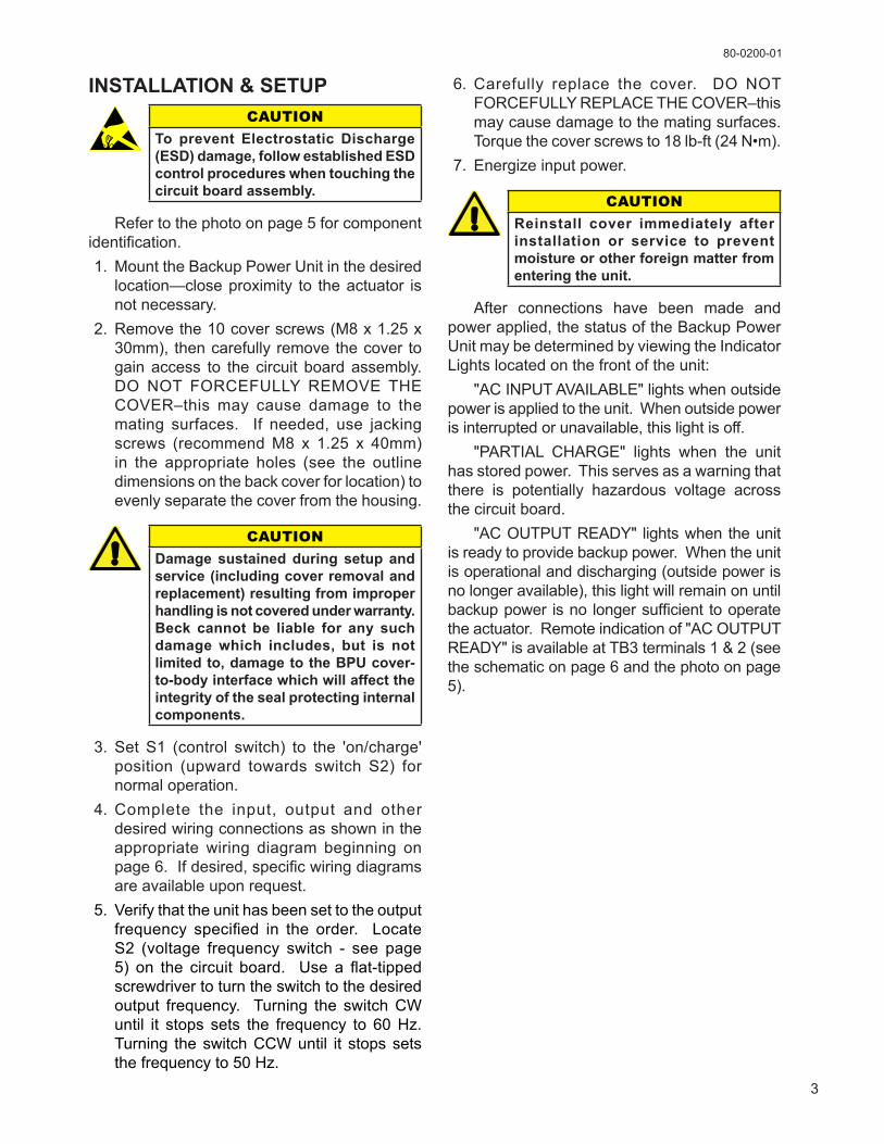
6. Carefully replace the cover. DO NOTFORCEFULLYREPLACETHECOVER–thismaycausedamagetothematingsurfaces.Torquethecoverscrewsto18lb-ft(24N•m).
7. Energizeinputpower.
CAUTIONReinstall cover immediately after installation or service to prevent moisture or other foreign matter from entering the unit.
After connections have been made andpowerapplied,thestatusoftheBackupPowerUnitmaybedeterminedbyviewingtheIndicatorLightslocatedonthefrontoftheunit: "ACINPUTAVAILABLE"lightswhenoutsidepowerisappliedtotheunit.Whenoutsidepowerisinterruptedorunavailable,thislightisoff. "PARTIAL CHARGE" lights when the unithasstoredpower.Thisservesasawarningthatthere is potentially hazardous voltage acrossthecircuitboard. "ACOUTPUTREADY" lightswhentheunitisreadytoprovidebackuppower.Whentheunitisoperationalanddischarging(outsidepowerisnolongeravailable),thislightwillremainonuntilbackuppower isno longersufficient tooperatetheactuator.Remoteindicationof"ACOUTPUTREADY"isavailableatTB3terminals1&2(seetheschematiconpage6andthephotoonpage5).
4
80-0200-01
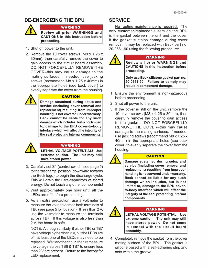
DE-ENERGIZING THE BPuWARNING
Review all prior WARNINGS and CAuTIONS in this instruction before proceeding.
1. Shutoffpowertotheunit.2. Removethe10coverscrews(M8x1.25x
30mm), thencarefullyremovethecover togainaccess to the circuit boardassembly.DO NOT FORCEFULLY REMOVE THECOVER–thismay cause damage to themating surfaces. If needed, use jackingscrews(recommendM8x1.25x40mm)inthe appropriate holes (see back cover) toevenlyseparatethecoverfromthehousing.
CAUTIONDamage sustained during setup and service (including cover removal and replacement) resulting from improper handling is not covered under warranty. Beck cannot be liable for any such damage which includes, but is not limited to, damage to the BPu cover-to-body interface which will affect the integrity of the seal protecting internal components.
WARNING
LETHAL VOLTAGE POTENTIAL! use extreme caution. The unit may still have stored power.
3. CarefullysetS1(controlswitch,seepage5)tothe'discharge'position(downwardtowardstheBecklogo)tobeginthedischargecycle.Thiswilldraintheultra-capacitorsofstoredenergy.Donottouchanyothercomponents!
4.Wait approximately one hour until all theLEDsareoffbeforeproceeding.
5. Asanextraprecaution,useavoltmeter tomeasurethevoltageacrossbothterminalsofTB6(seepage5forlocation).Iflessthan2V,use thevoltmeter tomeasure the terminalsacrossTB7.Ifthisvoltageisalsolessthan2V,theboardissafe.
NOTE:Althoughunlikely,ifeitherTB6orTB7havevoltagehigherthan2V,buttheLEDsareoff,atleastoneoftheLEDsmayneedtobereplaced.Waitanotherhour,thenremeasurethevoltageacrossTB6&TB7toensurelessthan2Varepresent.ReturntothefactoryforLEDreplacement.
SERVICE No routinemaintenance is required. Theonly customer-replaceable item on the BPUis thegasket between theunit and the cover.If the gasket sustains damage during coverremoval,itmaybereplacedwithBeckpartno.20-0661-90usingthefollowingprocedure:
WARNINGReview all prior WARNINGS and CAuTIONS in this instruction before proceeding.
Only use Beck silicone gasket part no. 20-0661-90. Failure to comply may result in component damage.
1. Ensure the environment is non-hazardousbeforeproceeding.
2. Shutoffpowertotheunit.3. If thecover is still on theunit, remove the
10coverscrews(M8x1.25x30mm),thencarefully remove the cover to gain accessto the gasket. DO NOT FORCEFULLYREMOVETHECOVER–thismay causedamagetothematingsurfaces. Ifneeded,usejackingscrews(recommendM8x1.25x40mm) in theappropriate holes (seebackcover)toevenlyseparatethecoverfromthehousing.
CAUTIONDamage sustained during setup and service (including cover removal and replacement) resulting from improper handling is not covered under warranty. Beck cannot be liable for any such damage which includes, but is not limited to, damage to the BPu cover-to-body interface which will affect the integrity of the seal protecting internal components.
WARNING
LETHAL VOLTAGE POTENTIAL! use extreme caution. The unit may still have stored power. Do not come in contact with the circuit board assembly.
4. Completelyremovethegasketfromthecovermatingsurfaceof theBPU. Thegasket issiliconebasedwithaself-adheringstripandsetswithinthegroove.

5
80-0200-01
5. Ensure the groove is clean. Remove thebacking fromtheself-adheringstripon thenewgasket. Orient thegasketso that theadhesiveistowardthegrooveonthematingsurfaceoftheunit.
6. Thegasketshouldbemountedcompletelyandsmoothlywithinthegroove(nokinks).
7. EnsureswitchS1isinthedesiredposition.8. Carefully replace the cover. DO NOT
FORCEFULLYREPLACETHECOVER–thismaycausedamagetothematingsurfaces.Torquethecoverscrewsto18lb-ft(24N•m).
9. Energize input power to resume normaloperation.
BACKUP POWER UNIT CIRCUIT BOARD ASSEMBLY
S2 - VOLTAGE FREQuENCY SWITCH(Determines the frequency relevant to the output (50 or 60 Hz). Turning the switch CW selects 60 Hz, CCW selects 50 Hz. For safety, this switch should only be turned when the unit is completely de-energized).
S1 - CONTROL SWITCH(A two position switch. The 'on/charge' position (up) allows for normal operation; the 'discharge' position (shown) causes the ultra-capacitors to begin a discharge cycle—depending on the charge, it may take approx. 1 hour before the "PARTIAL CHARGE" light shuts off).
CuSTOmERWIRINGCONNECTIONS(TB2, 1–6)
POWER INPuT(TB1, 3 & 4)
CuSTOmERWIRINGCONNECTIONSFOR REmOTE "AC OuTPuT READY" INDICATION(TB3, 1 & 2)
TB7(120 V dc bus)
TB6(18 V dc bus)
POWER OuTPuT(TB1, 1 & 2)

6
80-0200-01
BACKUP POWER UNIT WIRING SCHEMATIC
mOuNTING HOLES(Rear View)
8 9/16(217)
8 5/8(219)
12 1/16(306)
JackingScrews
2 5/8(67)
11/32 DIA. THRU(3) PLACES
5 1/4(133)
7 1/2(191)
3(76)
Dimensionsareininches&(mm)andaresubjecttochangewithoutnotice
OUTLINE DIMENSIONS
RE
D
YE
L
OR
G
GR
N
BLKBLU
BLK
WH
T
FIELD-WIRING TERMINAL(CAPACITY: #12 AWG (3.31 mm2) wire)
#
3TB1
4
LINE
J2 -
3
J2 -
1
J4 -
1
J4 -
2
NEUTRAL
1
TB1
2
LINE 1
LINE 2
120VAC
GGROUND
INPUTVAC POWER
OUTPUT
TB4
- 1
TB5
- 1
TB5
- 2
TB4
- 2
K1
J7 -
4
J7 -
9
J7 -
3
J7 -
2
J7 -
1
J7 -
8
J7 -
7
J7 -
6
1 374BA 96
1
2
8
7
6
5
4
3
K2
1
2
3
4
5
6
TB2
OPTIONALDUAL
CAPACITORBANK
CONNECTIONS
1
2
AC OUTPUT*READY
STATUS RELAY
TB3
L1T1
YE
L
OR
G
BR
N
RE
D
RE
D
BLK
RED BLK
*CONTACT RATED MAX. 80 mA @ 120 VAC / VDC
J5-1
J5-2
TB6-1
TB6-2
J5-3
J6-1
J6-2
J6-3
J5-1
J5-2
TB6-1
TB6-2
J5-3
J6-1
J6-2
J6-3
CIRCUITBOARDASSY.
OPTIONALCAPACITOR
BOARDASSY.
7
80-0200-01
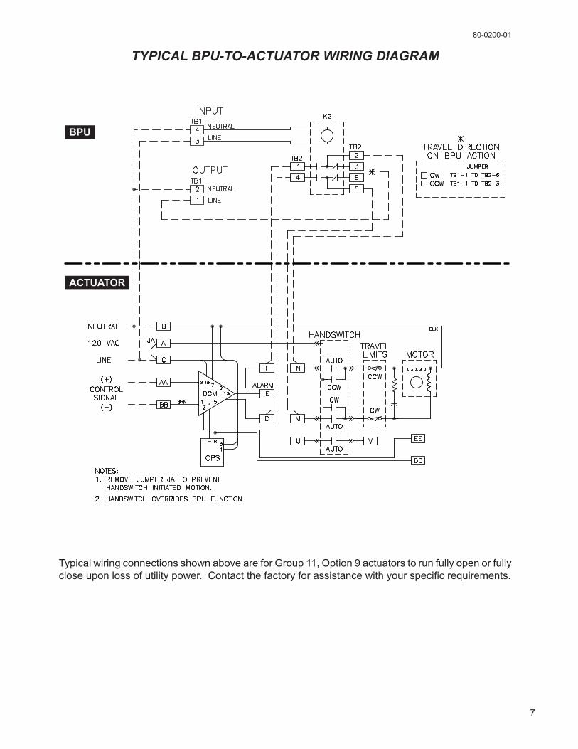
TYPICAL BPU-TO-ACTUATOR WIRING DIAGRAM
BPU
ACTUATOR
TypicalwiringconnectionsshownaboveareforGroup11,Option9actuatorstorunfullyopenorfullycloseuponlossofutilitypower.Contactthefactoryforassistancewithyourspecificrequirements.
6/16
11 TERRY DRIVE NEWTOWN, PENNSYLVANIA 18940 USAPHONE: 215-968-4600 FAX: 215-860-6383 E-MAIL: [email protected] www.haroldbeck.com
HAROLD BECK & SONS, INC.
R
Made in USA