
For limiting case(torque = 0): - Home | Students'...
13
BI-PED ROBOTIC LEGS UTSAV GUPTA, VARUN VERMA, SHIVAM SONI, DEPAK PAWAR, VIVEK VERMA SUMMER PROJECT-2014 ROBOTICS CLUB SCIENCE AND TECHNOLOGY COUNCIL INDIAN INSTITUE OF TECHNOLOGY, KANPUR WIKI LINK: students.iitk.ac.in/projects/wiki/doku.php? id=2014robo:deepak_pawar_shivam_soni_utsav_gupta_varun_verma_vivek_verma ABSTRACT The focus of this paper is to create a pair of Bi-Ped Robotic legs which can move autonomously, detecting obstacles and avoiding them or can be controlled by your own laptop or mobile through Bluetooth pairing. The paper shows proper documentation of all the knowledge needed, materials and components with their specifications needed , step by step progress , various calculations involved and pros and cons of every important decision taken during the making of the Bi-Ped legs. It also includes the source of every small information we got from the various websites , our mentors and other papers on the same topic. It also shows the where we can find various high end components necessary for building the Bi-Ped legs and their prices and why we chose certain specifications for them or why were these specifications preferred over other any specifications. The project under the ROBOTICS CLUB IITK is to make Bi-Ped legs but is aimed to go even further by making the upper body and hands ultimately leading us to making it into a fully operational humanoid robot. INTRODUCTION
-
Upload
duongkhuong -
Category
Documents
-
view
215 -
download
2
Transcript of For limiting case(torque = 0): - Home | Students'...

BI-PED ROBOTIC LEGS
UTSAV GUPTA, VARUN VERMA, SHIVAM SONI, DEPAK PAWAR, VIVEK VERMA
SUMMER PROJECT-2014ROBOTICS CLUB
SCIENCE AND TECHNOLOGY COUNCILINDIAN INSTITUE OF TECHNOLOGY, KANPUR
WIKI LINK: students.iitk.ac.in/projects/wiki/doku.php?id=2014robo:deepak_pawar_shivam_soni_utsav_gupta_varun_verma_vivek_verma
ABSTRACTThe focus of this paper is to create a pair of Bi-Ped Robotic legs which can move autonomously, detecting obstacles and avoiding them or can be controlled by your own laptop or mobile through Bluetooth pairing.The paper shows proper documentation of all the knowledge needed, materials and components with their specifications needed , step by step progress , various calculations involved and pros and cons of every important decision taken during the making of the Bi-Ped legs. It also includes the source of every small information we got from the various websites , our mentors and other papers on the same topic. It also shows the where we can find various high end components necessary for building the Bi-Ped legs and their prices and why we chose certain specifications for them or why were these specifications preferred over other any specifications. The project under the ROBOTICS CLUB IITK is to make Bi-Ped legs but is aimed to go even further by making the upper body and hands ultimately leading us to making it into a fully operational humanoid robot.
INTRODUCTION
In general, a bipedal locomotion system consists of several members that are interconnected with actuated joints. In essence, a man-made walking robot is nothing more than a robotic manipulator with a detachable and moving base. Design of bipedal robots has been largely influenced by the most sophisticated and versatile biped known to man, the man himself. Almost any model or machine can be characterized as having two lower limbs that are connected through a central member. Although the complexity of the system depends on the number of degrees of freedom, the existence of feet structures, upper limbs, etc., it is widely known that even extremely simple unactuated systems can generate ambulatory motion. A bipedal locomotion system can have a very simple structure with three point masses connected with
massless links or very complex structure that mimics the human body. In both cases, the system can walk several steps. The robotics community has been involved in the field of modeling and control of bipeds for many years. With advances in science and technology, the interest to study the human walking has developed the demand for building the Bipedal robots. The development of Bipedal walking robot involves research in heterogeneous areas. This Paper describes the first attempt in building the Bipedal walking robot.
Design of Bipedal robot involves equal amount of mechanical and electronics considerations. There are many factors which are to be considered are cost, actuator, size, weight and controlling of actuators. All these factors have been considered and designed. The robot has six degrees of freedom, with three degrees of freedom per leg. Each leg has Hip, Knee and Ankle. The hip and knee Joints are actuated in vertical plane (Pitch) and the ankle joints are actuated in horizontal plane (Roll). The Biped is capable of demonstrating walking without any torso arrangement (or) weight shifting mechanism and uses dynamic walking control.
MECHANICAL DESIGN
The Mechanical design forms the basis for developing this type of walking robots. The mechanical design is divided into four phases: A: Determining the Mechanical constraints. B: Conceptual Design C: Building the Prototype model D: Specification and Fabrication of the model.
A.) Determining the Mechanical Constraints There are various design considerations when designing a Bipedal robot. Among them, the major factors that have to be considered are:-
1) Robot Size Selection: Robot size plays a major role. Based on this the Cost of the Project, Materials required for fabrication and the no of Actuators required can be determined. In this project miniature size of the robot is preferred so a height of 263.59mm is decided which includes mounting of the control circuits, but the actual size of the robot is 185.37mm without controlling circuits.2) Degrees of Freedom (D.O.F): Human leg has got Six Degrees of freedom (Hip – 3 D.O.F, Knee – 1 D.O.F, Ankle – 2 D.O.F), but implementing all the Six D.O.F is difficult due to increase in cost of the project and controlling of the actuators which become complex, so in this project reduced degrees of freedom is aimed so 3 D.O.F per leg has been finalized (Hip – 1 D.O.F, Knee – 1 D.O.F, Ankle – 1 D.O.F). 3) Link Design: In this project U-shaped bracket like arrangement called servo frames and flat brackets called servo clamps are used for various joints and connecting servos to the leg parts wherever needed. Servo frames used are of various lengths according to the various lengths of the different parts of the leg whereas the servo flat brackets will join the servo motors to the different joints.
4) Stability: With Biped mechanism, only two points will be in contact with the ground surface. In order to achieve effective balance, actuator will be made to rotate in sequence and the robot structure will try to balance. If the balancing is not proper, in order to maintain the Centre of Mass, dead weight would be placed in inverted pendulum configuration with 1 D.O.F. This dead weight will be shifted from one side to the other according to the balance requirement. But in this project no such configuration is used. 5) Foot Pad Design:The stability of the robot is determined by the foot pad. Generally there is a concept that over sized and heavy foot pad will have more stability due to more contact area. But there is a disadvantage in using the oversized and heavy foot pad, because more material will be required leading to increased costs and no significant contribution to the stability of the system. This will also force the servo motors to apply more
torque for lifting the various leg parts. By considering this disadvantage an optimal sized foot pad was used. Dimensions of the foot pad are 119.88X65.255mm.
B.) Conceptual Design
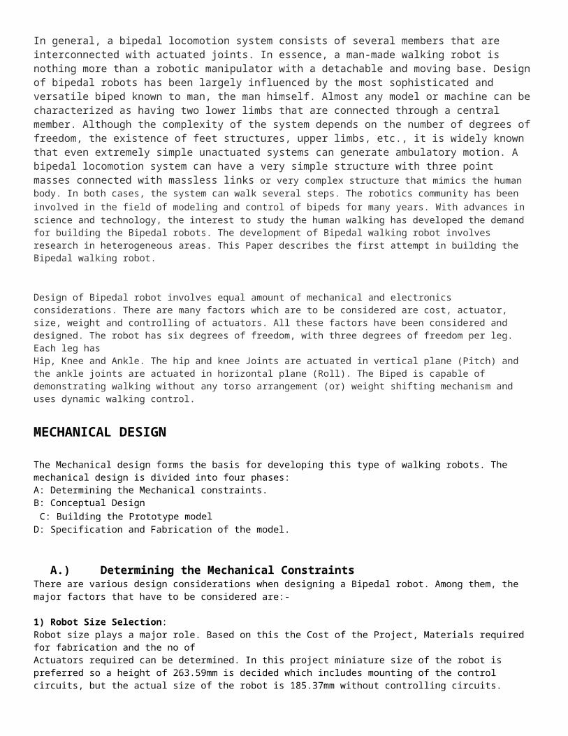
Initially the Bipedal robot was conceived with ten degrees of freedom. Due to constraints faced in controlling greater number degrees of freedom we, a new design was arrived with the knowledge gathered from developing previous Bipedal models. The new design has got Six degrees of freedom with three degrees of freedom per leg. Optimal distance was maintained between the legs to ensure that legs don’t hit each other while walking.
All the 3D models are developed using AutoCAD Inventor.
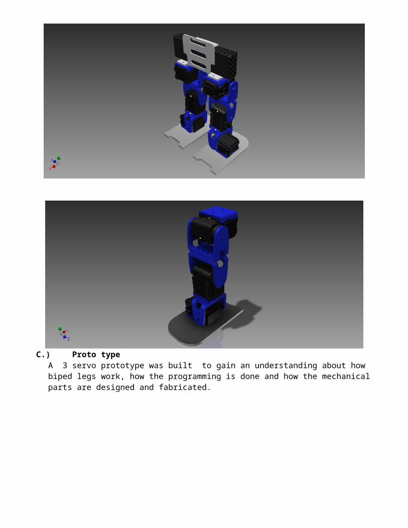
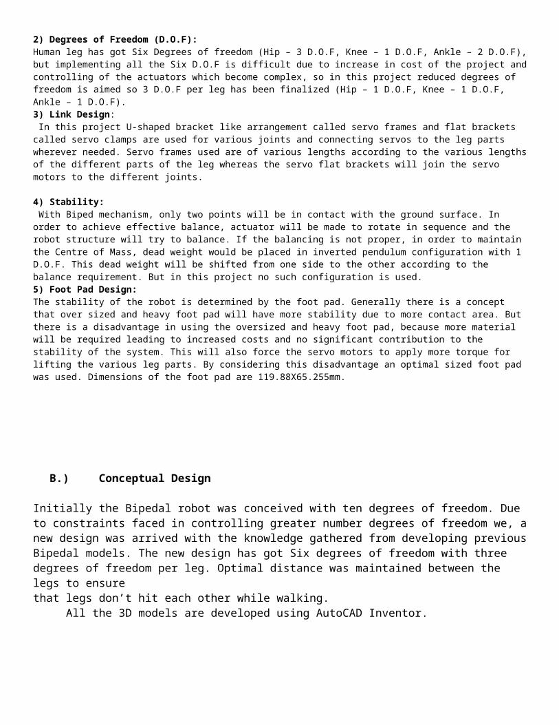
C.) Proto type A 3 servo prototype was built to gain an understanding about how biped legs work, how the programming is done and how the mechanical parts are designed and fabricated.
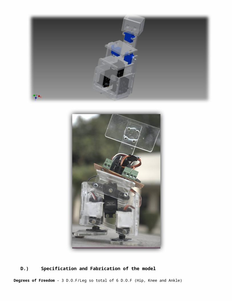
D.) Specification and Fabrication of the model
Degrees of Freedom – 3 D.O.F/Leg so total of 6 D.O.F (Hip, Knee and Ankle) Dimensions:
Height – 263.59mmWidth – 119.88mm
Leg Length – 185.37mm Foot pad:
Length – 119.88mmWidth – 65.255mm
Servo Frames: Length – 44.28mm, Width – 48.31mm
Servo Clamps:Length – 48.52mmWidth – 36.00mm
Estimated Servo Clamp Weight - 50gms – 65gms Servo motor Weight - 55gms Total estimated weight for a link (Servomotor + Servomotor Bracket) - 120gms For 6 links (i.e. 2Legs): 720gms approx Foot pad weight (2 legs):60gms. Circuits & Batteries: 300 - 400gms approx Total weight of the robot = 1.180Kg approx.

WALKING GAIT Generally walking cycle consists of two steps namely Initialization and Walking 1) Initialization: In the Initialization step the robot will be in balanced condition and in this step the servomotors are made to return to home position. This will certainly help the robot to advance into the next step. 2) Walking: Walking step is further classified into six phases.
Phase 1 – Double Support: In this phase both the legs are in same line and the centre of mass is maintained between the two
legs.
Phase 2 – Single Support (Pre-Swing): In this phase both the ankle joints are in actuated in roll orientation which shifts the centre of mass towards the left leg and the right leg will be lifted up from the ground. Phase 3 – Single Support (Swing): In this phase, the right leg is lifted further and made to swing in the air. Hip and knee joints are actuated in pitch orientation so that right leg is moved forward. Phase 4 – Post Swing: In this phase the lifted leg is placed down with the actuation of ankle joints. Phase 5 and 6 are the mirror image of Phase 2 and Phase 3.
After Phase 6, motion continues with a transition to Phase 1 and the walking continues.
. It takes approximately 30 seconds to complete one walking cycle (all 6 phases). Bipedal robot has a step length of approximately 10mm. The Robot has the capability of carrying a dead weight of approximately 150gms.
CONTROLLING OF BIPEDAL ROBOT
Generally any robot has a combination of motors and sensors, which are controlled by microcontrollers. There are wide varieties of motors, sensors and microcontrollers available. In this project Arduino Mega 2560 is used as a microcontroller and for Six D.O.F, each D.O.F has one AX-12 servomotor. The Arduino board has the capability to control up to eight actuators but the servos used in our project()and it has a provision for providing sensory inputs to the controller such as an ultrasonic sensor in our case.A Bluetooth module is used to make transmission of signal from a computer to the arduino wireless.
CALCULATION FOR RANGE OF SHIFT OF NORMAL REACTION

Total mass = 1.526 kgError(mass)= +_100 g { as we were expecting the material of
3D printing is of density 0.357 g/cm3 }
Case-(i) When bot is moving backward(limiting case)

For limiting case(torque = 0):N*[(119.88/2) – 17] = fs*(132) { wher N is normal reaction }
Since toppling will occur for static friction fs = ma { a is accelaration }
N*(42.94) = 132*m*aor
m*g*42.94 = m*a*132or
a = (10*42.94)/132 = 3.25 m/s2limiting acceleration in backward direction = 3.25 m/s2
Case-(ii) When bot is moving forward(limiting case)
N*76.94 = 132*m*aFrom this acc. is coming to be >>> 3.25 m/s2
Since our program is design in a way that every one cycle is divided into 20 frames to analyze the motion. From our calculation each cycle is around 1-2 seconds and one step is around 18 cm which
implies our acceleration of bot is <<<3.25 m/s2.Thus we have freedom to reduce our frame rate to 5-10 frames per cycle for dynamic motion and
reduce the delay time between two frame in order to increase the speed of biped without toppling at all.
THE FINAL PRODUCT

TASKS IT CAN PERFORM
WALK IN FORWARD, BACKWARD, LEFT AND RIGHT DIRECTION.

KICK ANY OBJECT IN FRONT OF IT. HEAD BUTT ANY OBSTACLE. DETECT OBSTACLES SUCH AS WALL AND AVOID THEM WHEN IT
OPERATES AUTONOMOUSLY.
TASKS IT CAN BE AIMED FOR
IF FALLEN IT CAN GET UP ON ITS OW. RUN OR WALK VERY FAST. JUMP CLIMB STAIRS A FULL HUMANOID ROBOT WITH HANDS AND A HEAD CPABLE OF
IMAGE PROCESSING, PICKING UP THINGS,ETC
MAJOR PROBLEMS FACED
3-SERVO BI-PED LENGTH OF ITS LEGS AND DISTANCE BETWEEN THEM SURFACE AREA OF FEET LENGTHOF NECK SYNCHRONIZATION OF SERVOS
6-SERVO BI-PED ALMOST ALL THE PROBLEMS FACEDIN 3-SERVO BI-PED 3-D PRINTING OF VARIOUS PARTS VERY EXPENSIVE CODING AND USING THE AX-12A DYNAMEXIAL SERVOS TRANSMITTING AND RECEIVING SIGNALS FROM X-BEE. MAKING A CLEAN CIRCUIT WITHOUT SHORT CIRCUITING
CONNECTIONS.

JOINING THE SERVO FRAMES AND CLAMPS TO THE SERVOS. SETTING THE CORRECT AXIS OF THE SERVOS AND
DECIDING THE CORRECT ANGLES TO BE TURNED BY THE SERVOS.
FAULTY ARDUINOS AND EXCESS OF WIRES FROM SERVOS. BALANCING THE BI-PED LEGS AND MAINTAINING ITS CENTRE
OF GRAVITY.
SOLUTION
MANY ONLINE VIDEOS AND RESEARCH PAPERS AND THE HELP OF CO-ORDINATORS WERE USEFUL IN HELPING US OPERATING THE AX-12 SERVOS.
WE SHIFTED FROM X-BEE TO BLUTOOTH MODULE FOR WIRELESSLY TRANSMITTING THE SIGNALS TO THE BI-PED LEGS.
AFTER A LOT OF TRIALS AND TESTS WE WENT AHEAD WITH STICKING THE SERVOS TO THE FRAMES AND CLAMPS. ALSO A GPB BOARD WAS USED TO ENSURE CLEAN AND STRONG CONNECTIONS.
SINK TUBES WERE USED TO CLUB 3 WIRES FROM A SERVO THUS MAKING IT NEAT AND EASY TO CONNECT.
AFTER A LOT OF TRAILS AND TESTING THE AXIS AND ANGLE OF EACH SERVO WAS INDIVISUALLY SET AND THEN ALL THE 6 WERE TESTED TOGETHER.
THE PLACEMENT OF ARDUINO AND BATTERY WAS DECIDED AS SUCH TO BALANCE THE LEGS AND MAINTAIN THE CENTRE OF GRAVITY.
FUTURE PROSPECTS
These BI-PED legs can further be aimed into creating a full humanoid. First the hands can be added enabling it to walk and pick up things, punch obstacles and other functions. Then a head can also be attached enabling it to recognize colors through image

processing. More human like functions can be assigned to the robot leading it to become something bigger than only a pair of bipedal legs. A controller can also be made to manually handle the bot and make it perform tasks.


