For latest prices, please check AutomationDirect.com ... · KILLARK Hazardous Location Controls...
7
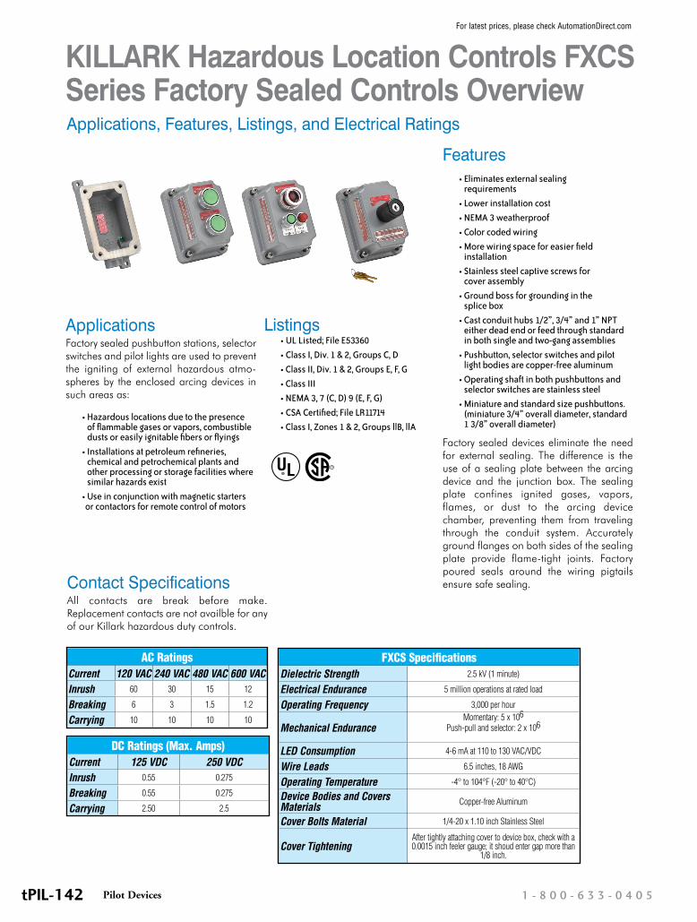
KILLARK Hazardous Location Controls FXCS Series Factory Sealed Controls Overview R Applications, Features, Listings, and Electrical Ratings Contact Specifications All contacts are break before make. Replacement contacts are not availble for any of our Killark hazardous duty controls. AC Ratings Current 120 VAC 240 VAC 480 VAC 600 VAC Inrush 60 30 15 12 Breaking 6 3 1.5 1.2 Carrying 10 10 10 10 DC Ratings (Max. Amps) Current 125 VDC 250 VDC Inrush 0.55 0.275 Breaking 0.55 0.275 Carrying 2.50 2.5 FXCS Specifications Dielectric Strength 2.5 kV (1 minute) Electrical Endurance 5 million operations at rated load Operating Frequency 3,000 per hour Mechanical Endurance Momentary: 5 x 10 6 Push-pull and selector: 2 x 10 6 LED Consumption 4-6 mA at 110 to 130 VAC/VDC Wire Leads 6.5 inches, 18 AWG Operating Temperature -4° to 104°F (-20° to 40°C) Device Bodies and Covers Materials Copper-free Aluminum Cover Bolts Material 1/4-20 x 1.10 inch Stainless Steel Cover Tightening After tightly attaching cover to device box, check with a 0.0015 inch feeler gauge; it shoud enter gap more than 1/8 inch. Applications Factory sealed pushbutton stations, selector switches and pilot lights are used to prevent the igniting of external hazardous atmo- spheres by the enclosed arcing devices in such areas as: • Hazardous locations due to the presence of flammable gases or vapors, combustible dusts or easily ignitable fibers or flyings • Installations at petroleum refineries, chemical and petrochemical plants and other processing or storage facilities where similar hazards exist • Use in conjunction with magnetic starters or contactors for remote control of motors Features • Eliminates external sealing requirements • Lower installation cost • NEMA 3 weatherproof • Color coded wiring • More wiring space for easier field installation • Stainless steel captive screws for cover assembly • Ground boss for grounding in the splice box • Cast conduit hubs 1/2”, 3/4” and 1” NPT either dead end or feed through standard in both single and two-gang assemblies • Pushbutton, selector switches and pilot light bodies are copper-free aluminum • Operating shaft in both pushbuttons and selector switches are stainless steel • Miniature and standard size pushbuttons. (miniature 3/4” overall diameter, standard 1 3/8” overall diameter) Factory sealed devices eliminate the need for external sealing. The difference is the use of a sealing plate between the arcing device and the junction box. The sealing plate confines ignited gases, vapors, flames, or dust to the arcing device chamber, preventing them from traveling through the conduit system. Accurately ground flanges on both sides of the sealing plate provide flame-tight joints. Factory poured seals around the wiring pigtails ensure safe sealing. Listings • UL Listed; File E53360 • Class I, Div. 1 & 2, Groups C, D • Class II, Div. 1 & 2, Groups E, F, G • Class III • NEMA 3, 7 (C, D) 9 (E, F, G) • CSA Certified; File LR11714 • Class I, Zones 1 & 2, Groups llB, llA 1-800-633-0405 Pilot Devices tPIL-142 For latest prices, please check AutomationDirect.com
Transcript of For latest prices, please check AutomationDirect.com ... · KILLARK Hazardous Location Controls...
KILLARK Hazardous Location Controls FXCS Series Factory Sealed Controls Overview
R
Applications, Features, Listings, and Electrical Ratings
Contact SpecificationsAll contacts are break before make. Replacement contacts are not availble for any of our Killark hazardous duty controls.
AC RatingsCurrent 120 VAC 240 VAC 480 VAC 600 VACInrush 60 30 15 12
Breaking 6 3 1.5 1.2
Carrying 10 10 10 10
DC Ratings (Max. Amps)Current 125 VDC 250 VDCInrush 0.55 0.275
Breaking 0.55 0.275
Carrying 2.50 2.5
FXCS SpecificationsDielectric Strength 2.5 kV (1 minute)
Electrical Endurance 5 million operations at rated load
Operating Frequency 3,000 per hour
Mechanical EnduranceMomentary: 5 x 10⁶
Push-pull and selector: 2 x 10⁶
LED Consumption 4-6 mA at 110 to 130 VAC/VDC
Wire Leads 6.5 inches, 18 AWG
Operating Temperature -4° to 104°F (-20° to 40°C)
Device Bodies and Covers Materials Copper-free Aluminum
Cover Bolts Material 1/4-20 x 1.10 inch Stainless Steel
Cover TighteningAfter tightly attaching cover to device box, check with a 0.0015 inch feeler gauge; it shoud enter gap more than
1/8 inch.
ApplicationsFactory sealed pushbutton stations, selector switches and pilot lights are used to prevent the igniting of external hazardous atmo-spheres by the enclosed arcing devices in such areas as:
• Hazardous locations due to the presence
of flammable gases or vapors, combustible dusts or easily ignitable fibers or flyings
• Installations at petroleum refineries, chemical and petrochemical plants and other processing or storage facilities where similar hazards exist
• Use in conjunction with magnetic starters or contactors for remote control of motors
Features • Eliminates external sealing
requirements• Lower installation cost• NEMA 3 weatherproof• Color coded wiring• More wiring space for easier field
installation• Stainless steel captive screws for
cover assembly• Ground boss for grounding in the
splice box• Cast conduit hubs 1/2”, 3/4” and 1” NPT
either dead end or feed through standard in both single and two-gang assemblies
• Pushbutton, selector switches and pilot light bodies are copper-free aluminum
• Operating shaft in both pushbuttons and selector switches are stainless steel
• Miniature and standard size pushbuttons. (miniature 3/4” overall diameter, standard 1 3/8” overall diameter)
Factory sealed devices eliminate the need for external sealing. The difference is the use of a sealing plate between the arcing device and the junction box. The sealing plate confines ignited gases, vapors, flames, or dust to the arcing device chamber, preventing them from traveling through the conduit system. Accurately ground flanges on both sides of the sealing plate provide flame-tight joints. Factory poured seals around the wiring pigtails ensure safe sealing.
Listings• UL Listed; File E53360 • Class I, Div. 1 & 2, Groups C, D• Class II, Div. 1 & 2, Groups E, F, G• Class III• NEMA 3, 7 (C, D) 9 (E, F, G)• CSA Certified; File LR11714• Class I, Zones 1 & 2, Groups llB, llA
1 - 8 0 0 - 6 3 3 - 0 4 0 5Pilot DevicestPIL-142
For latest prices, please check AutomationDirect.com

KILLARK XCS Series Cover Assemblies and Control Stations - Selector Switches
Listings• UL Listed; File E53360 • Class I, Div. 1 & 2, Groups C, D• Class II, Div. 1 & 2, Groups E, F, G• Class III• NEMA 3, 7 (C, D) 9 (E, F, G)• CSA Certified; File LR11714• Class I, Zones 1 & 2, Groups llB, llA
R
XCS Two-Position Spring Return Selector SwitchPart Number (Includes cover with device)
Price Description Left Position Left Contact
Left Position Right Contact
Right Position Left Contact
Right Position Right Contact
Legend Plate Marking*
XCS-0S2L3F $228.001 N.O. / 1 N.C., spring return
from right; requires SWB series deep style splice/device box
“OFF ON”
XCS Three-Position Spring Return Selector Switches
Part Number (Includes cover with device)
Price Description
Left Position
Left Contact
Left Position
Right Contact
Center Position
Left Contact
Center Position
Right Contact
Right Position
Left Contact
Right Position
Right Contact
Knob Color
Legend Plate
Marking*
XCS-0S3M6G $228.002 N.O., spring return to center from left and right; requires
SWB series deep style splice/device box
Black “HAND OFF AUTO”
XCS-0S3L6G $228.002 N.O., spring return to center
from right, maintained in center and left; requires SWB series deep style splice/device box
Black “HAND OFF AUTO”
XCS-0S3R6G $228.002 N.O., spring return to center from left, maintained in center and right; requires SWB series deep style splice/device box
Black “HAND OFF AUTO”
* We also offer a large selection of optional legend plates. See accessories later in this section.
Selector Switch
Pilot Devicesw w w . a u t o m a t i o n d i r e c t . c o m / p u s h b u t t o n s - l i g h t s tPIL-153
For latest prices, please check AutomationDirect.com

KILLARK Hazardous Location Controls - DimensionsXCS Series Cover Assemblies
XCS-0S2A1, -0S2A5 XCS-0S3C4, -0S3C5
XCS-0K2A1A, -0K2A5A XCS-0K3C4A, -0K3C5A
Dimensions in inches [mm]
Pilot Devicesw w w . a u t o m a t i o n d i r e c t . c o m / p u s h b u t t o n s - l i g h t s tPIL-167
For latest prices, please check AutomationDirect.com

KILLARK Hazardous Location Controls - DimensionsXCS Series Cover Assemblies
XCS-0S2A1, -0S2A5 XCS-0S3C4, -0S3C5
XCS-0K2L3F22A XCS-0K3M6G32A, -0K3L6G32A, -0K3R6G32A
Dimensions in inches [mm]
1 - 8 0 0 - 6 3 3 - 0 4 0 5Pilot DevicestPIL-168
For latest prices, please check AutomationDirect.com

KILLARK SWB Series Splice/Device Boxes For Use With XCS Cover Assemblies
Listings• UL Listed; File E53360 • Class I, Div. 1 & 2, Groups C, D• Class II, Div. 1 & 2, Groups E, F, G• Class III• NEMA 3, 7 (C, D) 9 (E, F, G)• CSA Certified; File LR11712• Class I, Zones 1 & 2, Groups llB, llA
R
SWB Device BodiesPart Number Price Description Hub Size (inches)
SWB-2 $40.00 Single gang / Dead-end 3/4
SWB-5 $41.00 Single gang / Feed-through 3/4
SWB-8 $78.00 Double gang / Dead-end 3/4
SWB-11 $79.00 Double gang / Feed-through 3/4
SWB-42 $103.00 Single gang / Dead-end / Deep style 3/4
SWB-45 $127.00 Single gang / Feed-through / Deep style 3/4
SWB-2 SWB-5 SWB-8
SWB-11 SWB-42
Pilot Devicesw w w . a u t o m a t i o n d i r e c t . c o m / p u s h b u t t o n s - l i g h t s tPIL-149
For latest prices, please check AutomationDirect.com

KILLARK Hazardous Location Controls - DimensionsSWB Series Splice/Device Boxes
SWB-2 SWB-5
SWB-42 SWB-45
Dimensions in inches [mm]
Pilot Devicesw w w . a u t o m a t i o n d i r e c t . c o m / p u s h b u t t o n s - l i g h t s tPIL-163
For latest prices, please check AutomationDirect.com

KILLARK Hazardous Location Controls - DimensionsSWB Series Splice/Device Boxes
SWB-8
SWB-11
Dimensions in inches [mm]
1 - 8 0 0 - 6 3 3 - 0 4 0 5Pilot DevicestPIL-164
For latest prices, please check AutomationDirect.com