
For Infrastructure Master Program Engineering Faculty...
60
Dr. Fahid Rabah , PE [email protected] ١ Pumping Stations Design For Infrastructure Master Program Engineering Faculty-IUG Dr. Fahid Rabah Water and environment Engineering [email protected] Lecture 5: Design of wastewater pumping stations
-
Upload
hoangkhanh -
Category
Documents
-
view
217 -
download
0
Transcript of For Infrastructure Master Program Engineering Faculty...
Dr. Fahid Rabah , PE [email protected] ١
Pumping Stations Design For Infrastructure Master Program
Engineering Faculty-IUG
Dr. Fahid
RabahWater and environment Engineering
Lecture 5: Design of wastewater pumping stations
Dr. Fahid Rabah , PE [email protected] ٢
Lecture 5: Design of wastewater pumping stations
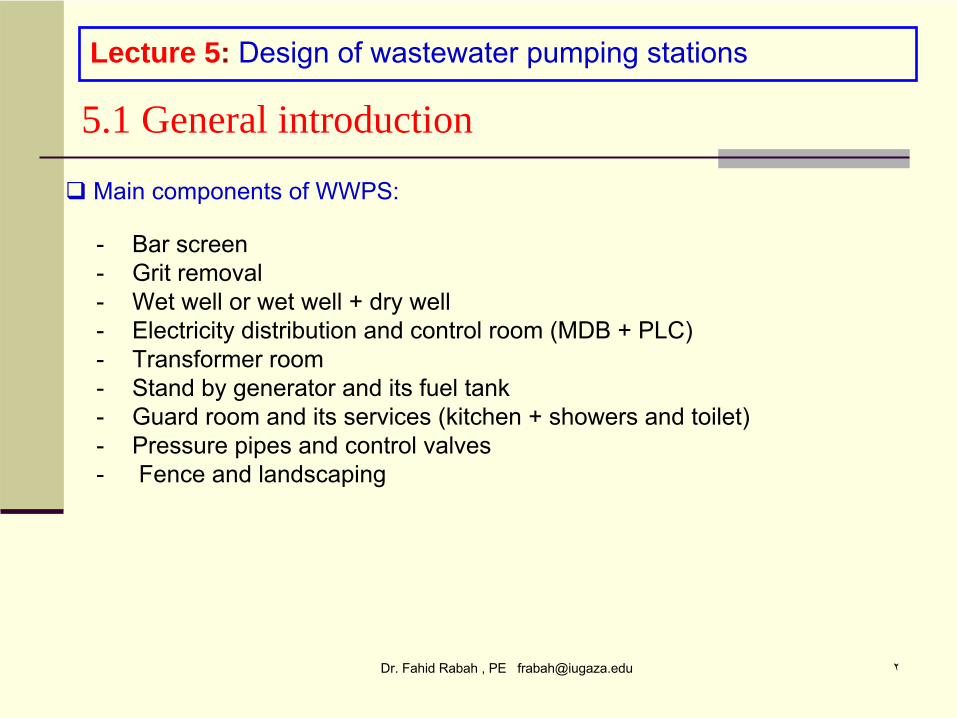
5.1 General introduction
Main components of WWPS:
-
Bar screen-
Grit removal
-
Wet well or wet well + dry well-
Electricity distribution and control room (MDB + PLC)
-
Transformer room-
Stand by generator and its fuel tank
-
Guard room and its services (kitchen + showers and toilet)-
Pressure pipes and control valves
-
Fence and landscaping
Dr. Fahid Rabah , PE [email protected] ٣
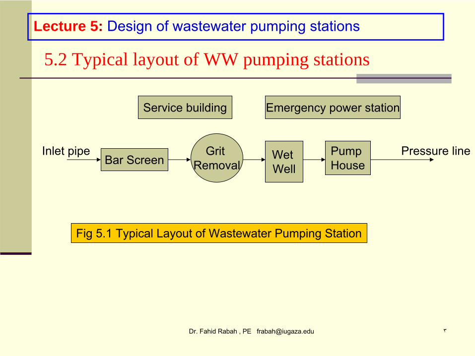
Grit Removal
Wet Well
Pump HouseBar Screen
Service building Emergency power station
Pressure lineInlet pipe
Fig 5.1 Typical Layout of Wastewater Pumping Station
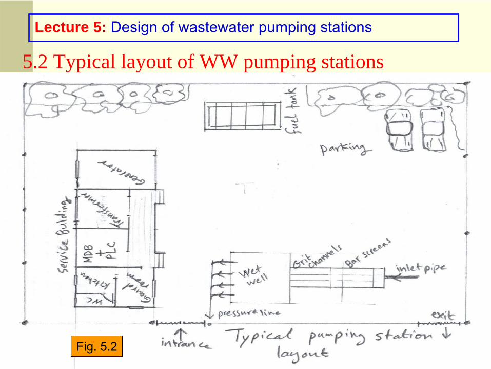
5.2 Typical layout of WW pumping stations
Lecture 5: Design of wastewater pumping stations
Dr. Fahid Rabah , PE [email protected] ٤Typical Layout of Wastewater Pumping Station
5.2 Typical layout of WW pumping stations
Lecture 5: Design of wastewater pumping stations
Fig. 5.2
Dr. Fahid Rabah , PE [email protected] ٥Manual Bar Screen
Mechanical Bar Screen
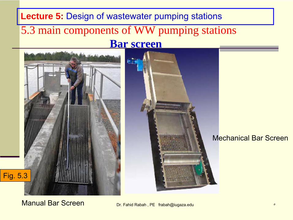
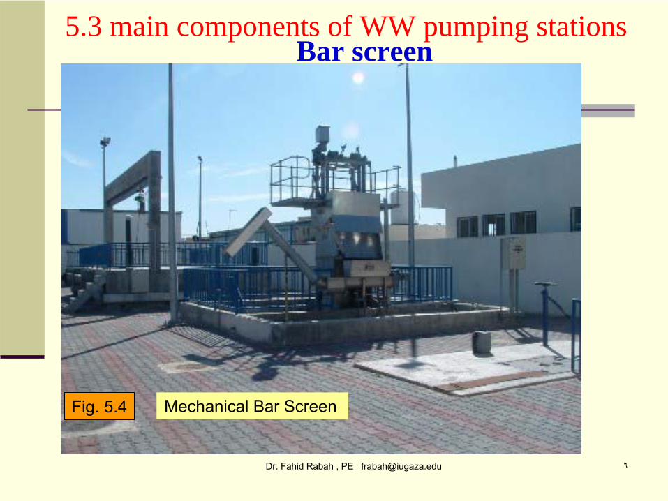
Lecture 5: Design of wastewater pumping stations5.3 main components of WW pumping stations
Bar screen
Fig. 5.3
Dr. Fahid Rabah , PE [email protected] ٦
Mechanical Bar Screen
5.3 main components of WW pumping stations Bar screen
Fig. 5.4
Dr. Fahid Rabah , PE [email protected] ٧
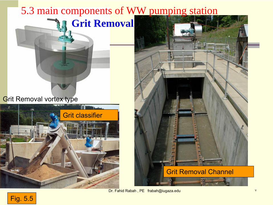
Grit Removal Channel
Grit Removal vortex type
5.3 main components of WW pumping station Grit Removal
Fig. 5.5
Grit classifier
Dr. Fahid Rabah , PE [email protected] ٨
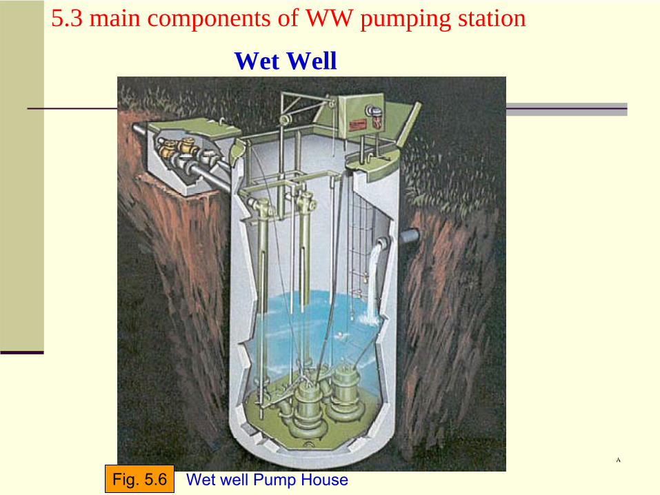
Wet well Pump House
5.3 main components of WW pumping station
Wet Well
Fig. 5.6
Dr. Fahid Rabah , PE [email protected] ٩
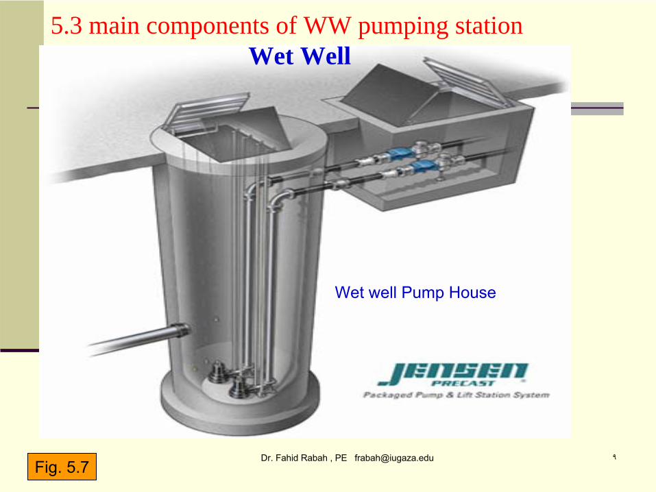
Wet well Pump House
5.3 main components of WW pumping station Wet Well
Fig. 5.7
Dr. Fahid Rabah , PE [email protected] ١٠
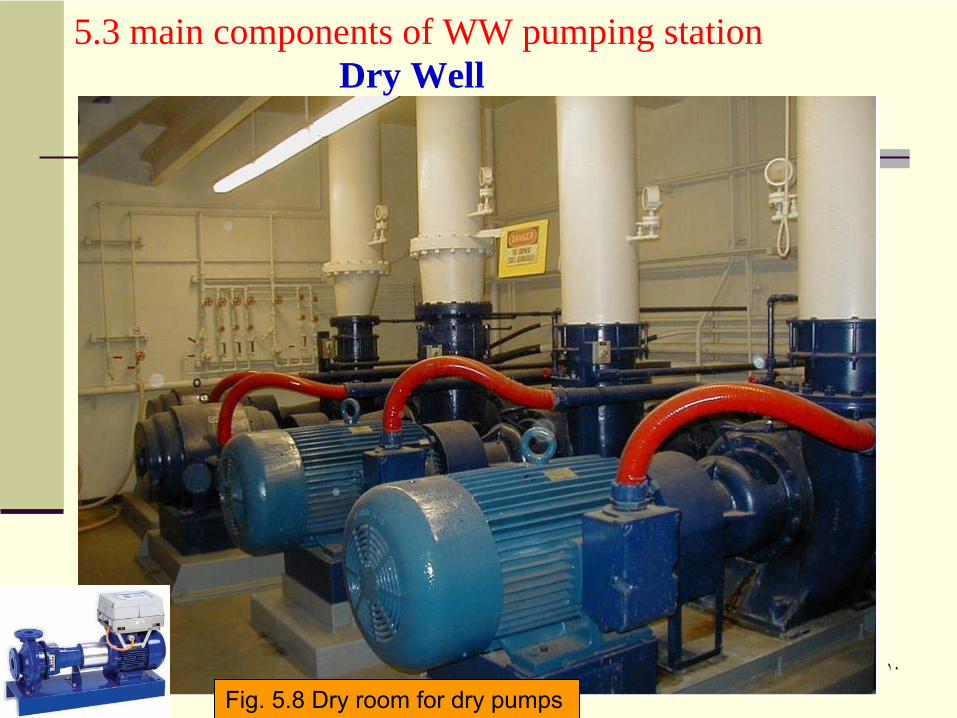
5.3 main components of WW pumping station Dry Well
Fig. 5.8 Dry room for dry pumps
Dr. Fahid Rabah , PE [email protected] ١١
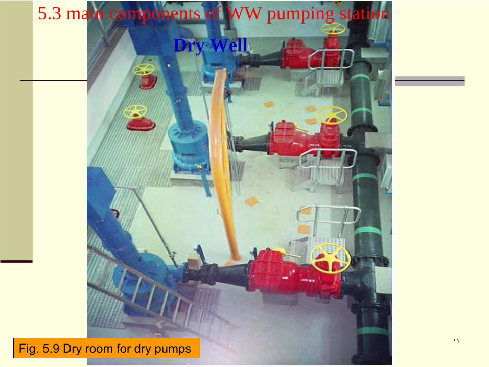
5.3 main components of WW pumping station
Dry Well
Fig. 5.9 Dry room for dry pumps
Dr. Fahid Rabah , PE [email protected] ١٢
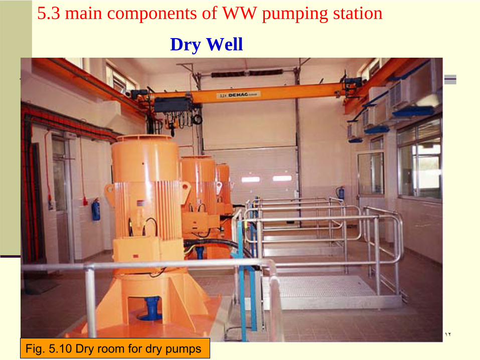
5.3 main components of WW pumping station
Dry Well
Fig. 5.10 Dry room for dry pumps
Dr. Fahid Rabah , PE [email protected] ١٣
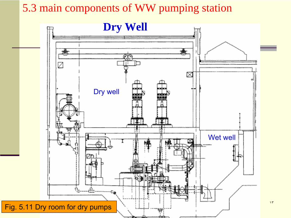
Wet well
Dry well
5.3 main components of WW pumping station
Dry Well
Fig. 5.11 Dry room for dry pumps
Dr. Fahid Rabah , PE [email protected] ١٤
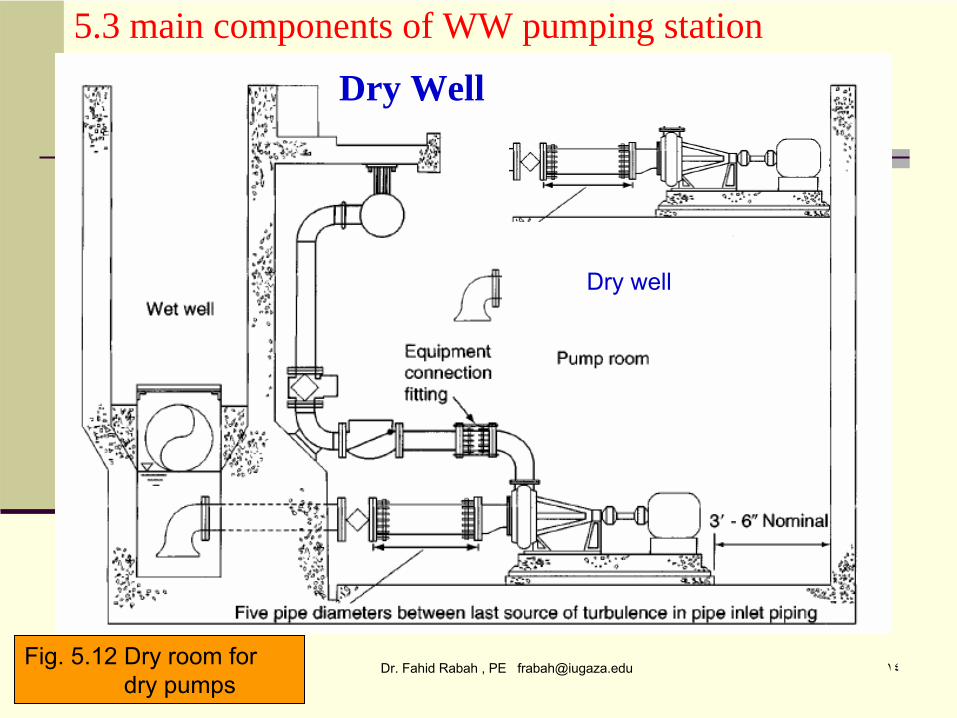
Dry well
5.3 main components of WW pumping station
Dry Well
Fig. 5.12 Dry room for dry pumps
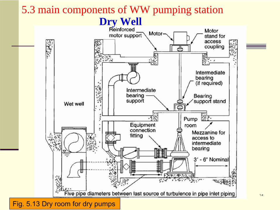
Dr. Fahid Rabah , PE [email protected] ١٥
5.3 main components of WW pumping station Dry Well
Fig. 5.13 Dry room for dry pumps
Dr. Fahid Rabah , PE [email protected] ١٦
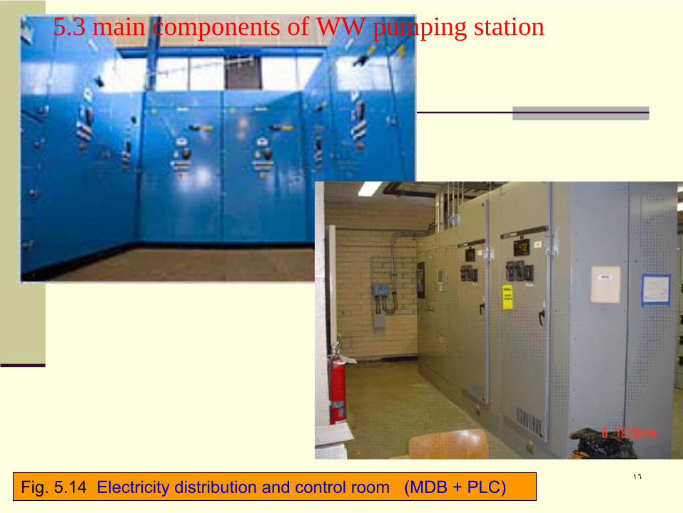
5.3 main components of WW pumping station
Fig. 5.14 Electricity distribution and control room (MDB + PLC)
Dr. Fahid Rabah , PE [email protected] ١٧
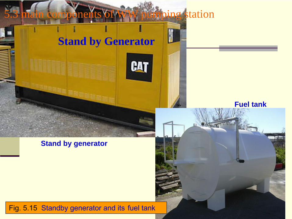
Stand by generator
5.3 main components of WW pumping station
Stand by Generator
Fuel tank
Fig. 5.15 Standby generator and its
fuel tank
Dr. Fahid Rabah , PE [email protected] ١٨
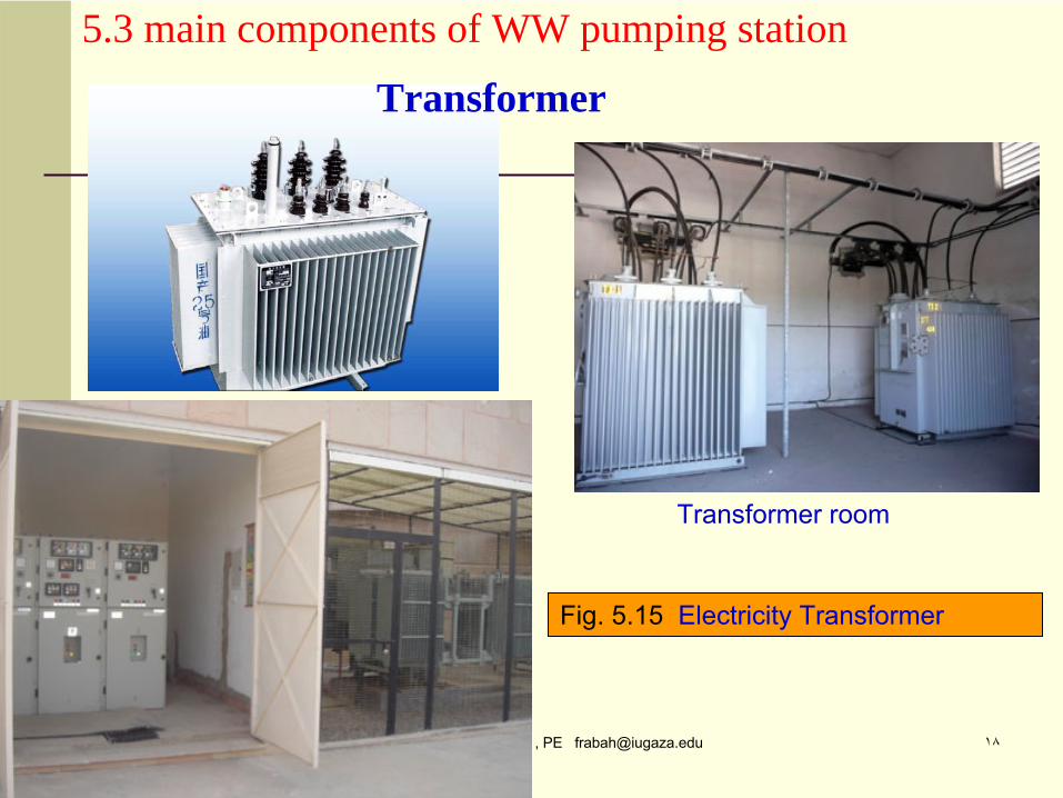
Transformer room
5.3 main components of WW pumping station
Transformer
Fig. 5.15 Electricity Transformer
Dr. Fahid Rabah , PE [email protected] ١٩
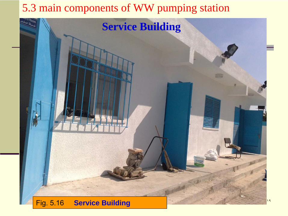
5.3 main components of WW pumping station
Service Building
Fig. 5.16 Service Building
Dr. Fahid Rabah , PE [email protected] ٢٠
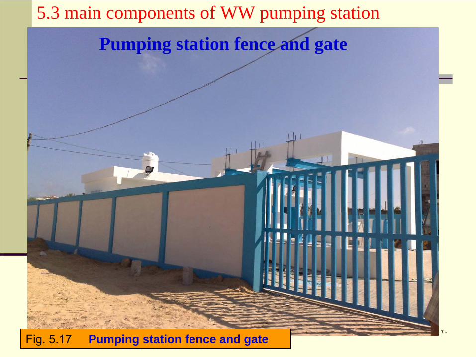
5.3 main components of WW pumping station
Pumping station fence and gate
Fig. 5.17 Pumping station fence and gate
Dr. Fahid Rabah , PE [email protected] ٢١
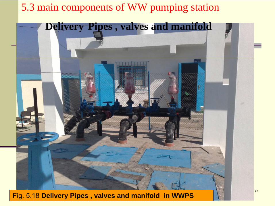
5.3 main components of WW pumping station
Delivery Pipes , valves and manifold
Fig. 5.18 Delivery Pipes , valves and manifold in WWPS
Dr. Fahid Rabah , PE [email protected] ٢٢
Lecture 5: Design of wastewater pumping stations
5.4 Design of the main components of WWPS
After the introduction to the main components of WWPS we will study the designof the following components:
-
Design of the general layout of the WWPS-
Design of Bar screen channel
-
Design of Grit removal channels-
Design of Wet well for submersible pumps
-
Design of Wet well and dry well for dry pumps-
Design of the delivery pipes and the pressure line
Dr. Fahid Rabah , PE [email protected] ٢٣Typical Layout of Wastewater Pumping Station
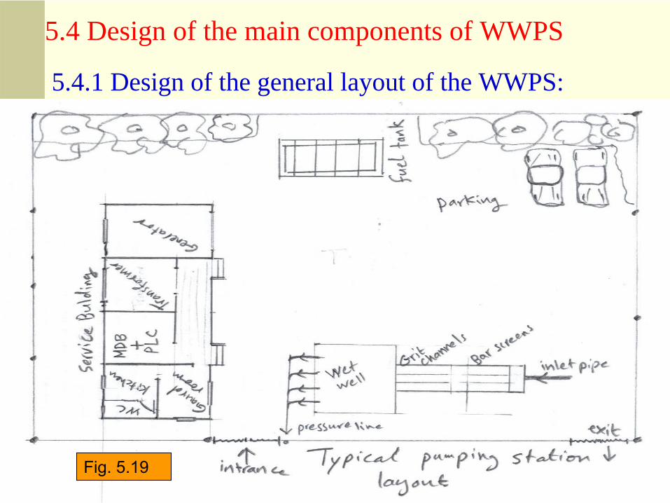
5.4.1 Design of the general layout of the WWPS:
5.4 Design of the main components of WWPS
Fig. 5.19
Dr. Fahid Rabah , PE [email protected] ٢٤
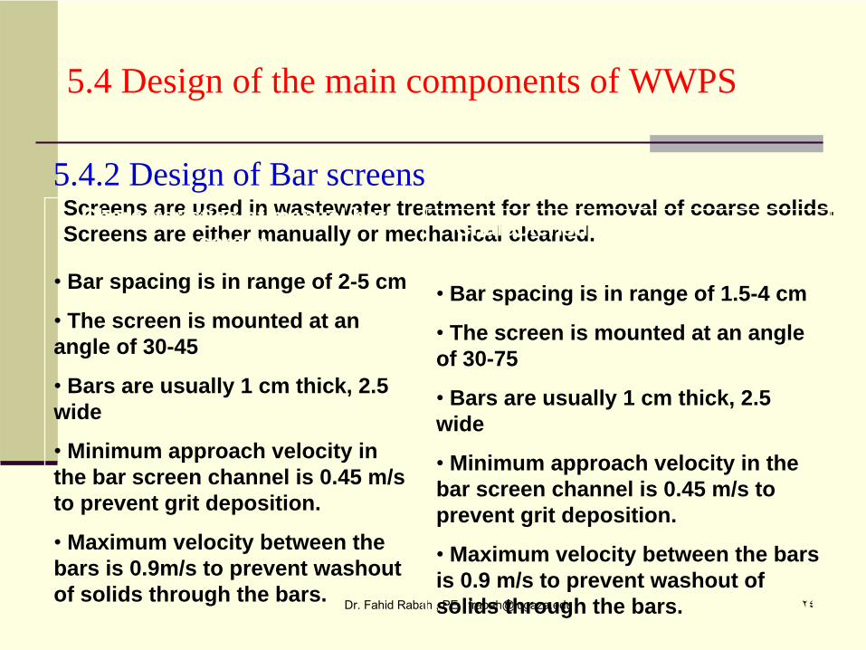
5.4.2 Design of Bar screensScreens are used in wastewater treatment for the removal of coarse solids. Screens are either manually or mechanical cleaned.
Characteristics of manual bar screen
• Bar spacing is in range of 2-5 cm
•
The screen is mounted at an angle of 30-45
•
Bars are usually 1 cm thick, 2.5 wide
•
Minimum approach velocity in the bar screen channel is 0.45 m/s to prevent grit deposition.
•
Maximum velocity between the bars is 0.9m/s to prevent washout of solids through the bars.
Characteristics of mechanical bar screen
• Bar spacing is in range of 1.5-4 cm
•
The screen is mounted at an angle of 30-75
•
Bars are usually 1 cm thick, 2.5 wide
•
Minimum approach velocity in the bar screen channel is 0.45 m/s to prevent grit deposition.
•
Maximum velocity between the bars is 0.9 m/s to prevent washout of solids through the bars.
5.4 Design of the main components of WWPS
Dr. Fahid Rabah , PE [email protected] ٢٥
Design of the bar screen channel (Approach Channel)
The cross section of the bar screen channel is determined from the continuity equation:
Qd
= AcVa
Ac = Qd / Va
Qd = design flow, m3/s
Ac = bar screen cross section, m2
Va = Velocity in the approach channel, m/s
Usually, rectangular channels are used, and the ratio between depth and width is taken as 1.5 to give the most efficient section.
7.01
2)( 22
gVVH ab
l
The head loss through the bar screen
Hl
= head loss
Va
= approach velocity, m/s
Vb
= Velocity through the openings, m/s
g = acceleration due to gravity, m/s2
5.4.2 Design of Bar screens
5.4 Design of the main components of WWPS
Dr. Fahid Rabah , PE [email protected] ٢٦
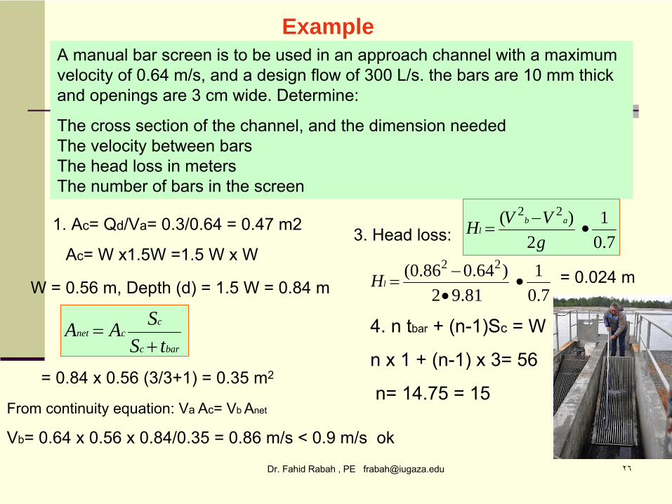
ExampleA manual bar screen is to be used in an approach channel with a maximum velocity of 0.64 m/s, and a design flow of 300 L/s. the bars are 10 mm thick and openings are 3 cm wide. Determine:
The cross section of the channel, and the dimension needed The velocity between bars The head loss in meters The number of bars in the screen
1. Ac= Qd/Va= 0.3/0.64 = 0.47 m2
Ac= W x1.5W =1.5 W x W
W = 0.56 m, Depth (d) = 1.5 W = 0.84 m
barc
ccnet
tSSAA
7.01
2)( 22
gVVH ab
l
7.01
81.92)64.086.0( 22
lH
= 0.84 x 0.56 (3/3+1) = 0.35 m2
From continuity equation: Va
Ac= Vb
Anet
Vb= 0.64 x 0.56 x 0.84/0.35 = 0.86 m/s
< 0.9 m/s
ok
3. Head loss:
= 0.024 m
4. n tbar
+ (n-1)Sc
= W
n x 1 + (n-1) x 3= 56
n= 14.75 = 15
Dr. Fahid Rabah , PE [email protected] ٢٧
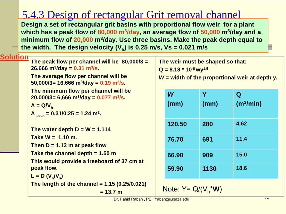
Design a set of rectangular grit basins with proportional flow weir for a plant which has a peak flow of 80,000 m3/day, an average flow of 50,000 m3/day and a minimum flow of 20,000 m3/day. Use three basins. Make the peak depth equal to the width. The design velocity (Vh ) is 0.25 m/s, Vs = 0.021 m/s
SolutionThe peak flow per channel will be 80,000/3 = 26,666 m3/day = 0.31 m3/s.The average flow per channel will be 50,000/3= 16,666 m3/day = 0.19 m3/s.The minimum flow per channel will be 20,000/3= 6,666 m3/day = 0.077 m3/s.A = Q/Vh
A peak = 0.31/0.25 = 1.24 m2.
The water depth D = W = 1.114Take W = 1.10 m. Then D = 1.13 m at peak flowTake the channel depth = 1.50 mThis would provide a freeboard of 37 cm at peak flow. L = D (Vh /Vs )The length of the channel = 1.15 (0.25/0.021)
= 13.7 m
The weir must be shaped so that:Q = 8.18 * 10-6 wy1.5
W = width of the proportional weir at depth y.
Q(m3/min)
Y(mm)
W(mm)
4.62280120.50
11.469176.70
15.090966.90
18.6113059.90
Note: Y= Q/(Vh
*W)
5.4.3 Design of rectangular Grit removal channel
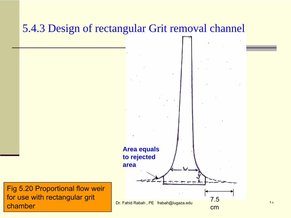
Dr. Fahid Rabah , PE [email protected] ٢٨7.5 cm
Fig 5.20 Proportional flow weir for use with rectangular grit chamber
5.4.3 Design of rectangular Grit removal channel
Area equals to rejected area

Dr. Fahid Rabah , PE [email protected] ٢٩
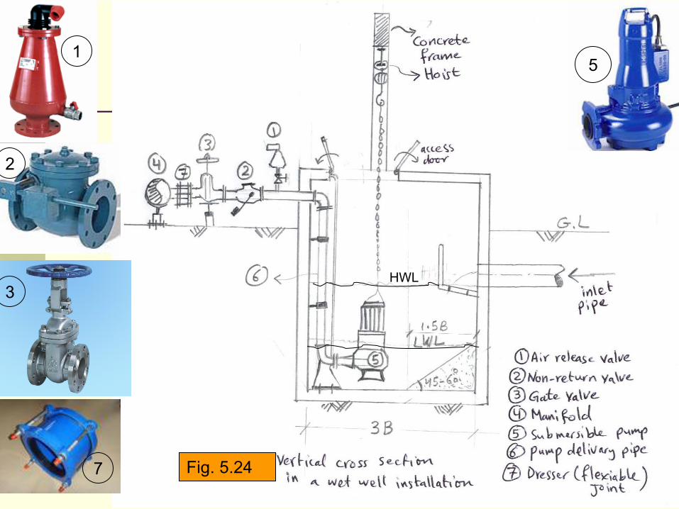
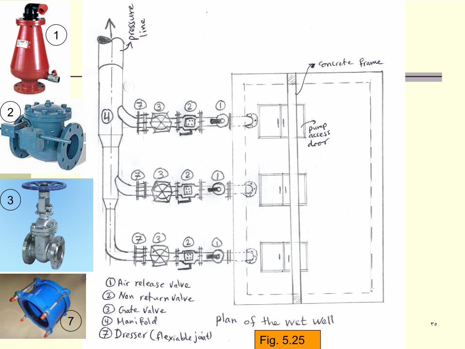
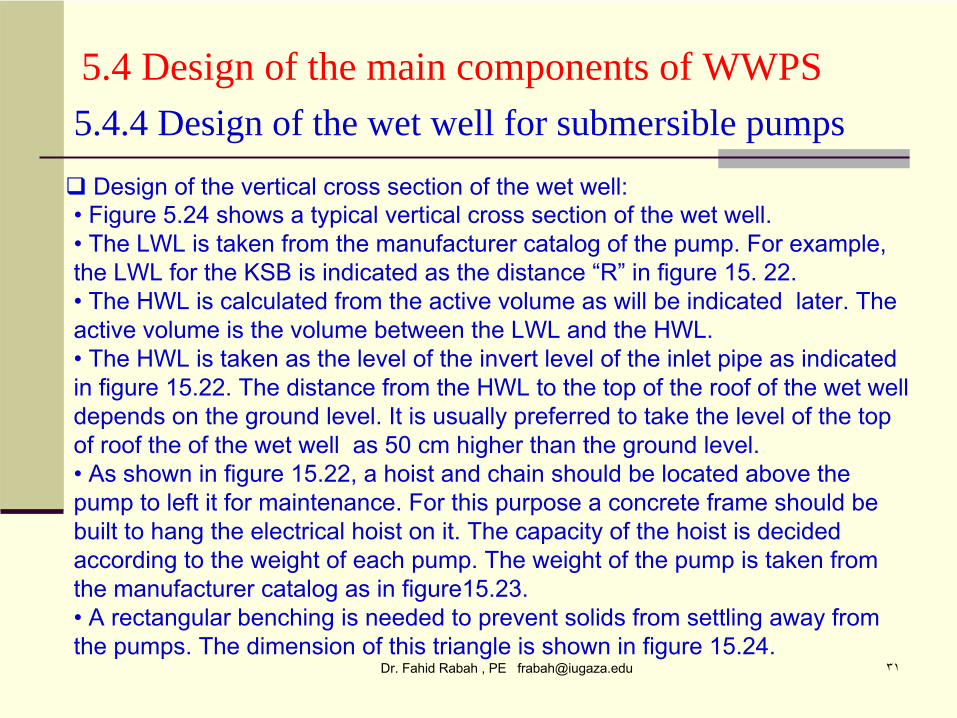
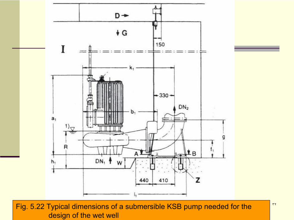
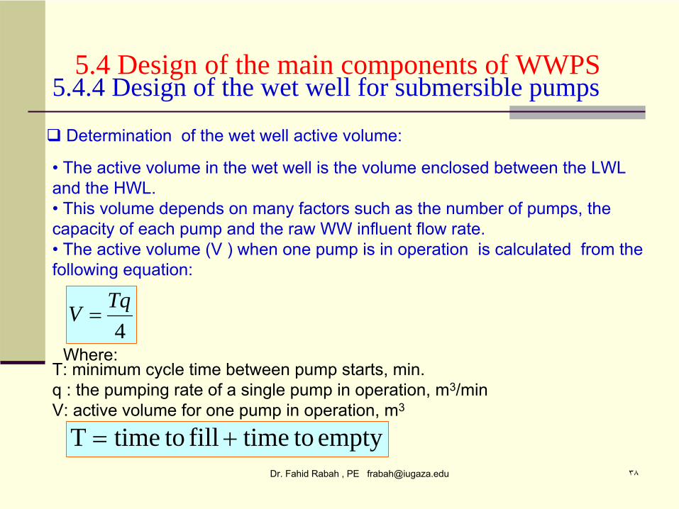
5.4 Design of the main components of WWPS
Design of horizontal cross section of the wet well:
5.4.4 Design of the wet well for submersible pumps
• The dimensions of the horizontal cross section of the wet well depends on thepump size and the recommended distance between the pumps. • Figure 5.21 shows the recommended dimensions of the horizontal cross section of the wet well
. Note that the diameter of the pump casing “D”
is the dimension
That decides the length of the wet well. • The second needed distance is B, the distance between the wet well wall and the center of the pump. The distance B is necessary to decide the width of the wet well. The distances D and B is taken from the pump catalogs as those shown in figures 15.23 and 15.22.• An inlet channel inside the wet well opposite to the inlet pipe
is usually needed to
As energy breaker to prevent turbulence in the wet well. The width of the channelis usually 50 to 70 cm and its height is equal to the inlet pipe diameter plus 30 cm. • Figure 15.25 shows a horizontal plan of the wet well at a level
above the concrete
frame.
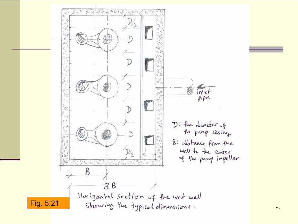
Dr. Fahid Rabah , PE [email protected] ٣٠Fig. 5.21
Dr. Fahid Rabah , PE [email protected] ٣١
5.4 Design of the main components of WWPS
Design of the vertical cross section of the wet well:
5.4.4 Design of the wet well for submersible pumps
• Figure 5.24 shows a typical vertical cross section of the wet well.•
The LWL is taken from the manufacturer catalog of the pump. For
example,
the LWL for the KSB is indicated as the distance “R”
in figure 15. 22. •
The HWL is calculated from the active volume as will be indicated later. The
active volume is the volume between the LWL and the HWL. •
The HWL is taken as the level of the invert level of the inlet pipe as indicated
in figure 15.22. The distance from the HWL to the top of the roof of the wet well depends on the ground level. It is usually preferred to take the
level of the top
of roof the of the wet well as 50 cm higher than the ground level. •
As shown in figure 15.22, a hoist and chain should be located above the
pump to left it for maintenance. For this purpose a concrete frame should be built to hang the electrical hoist on it. The capacity of the hoist is decided according to the weight of each pump. The weight of the pump is taken from the manufacturer catalog as in figure15.23.•
A rectangular benching is needed to prevent solids from settling away from
the pumps. The dimension of this triangle is shown in figure 15.24.
Dr. Fahid Rabah , PE [email protected] ٣٢Fig. 5.22 Typical dimensions of a submersible KSB pump needed for the design of the wet well
Dr. Fahid Rabah , PE [email protected] ٣٣Fig. 5.23 Typical dimensions of a submersible KSB pump needed for the design of the wet well
Dr. Fahid Rabah , PE [email protected] ٣٦
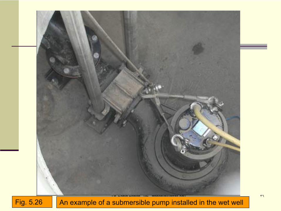
An example of a submersible pump installed in the wet wellFig. 5.26
Dr. Fahid Rabah , PE [email protected] ٣٧
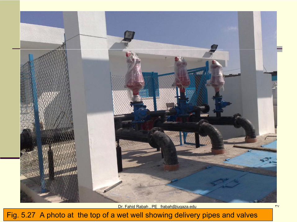
Fig. 5.27 A photo at the top of a wet well showing delivery pipes and valves
Dr. Fahid Rabah , PE [email protected] ٣٨
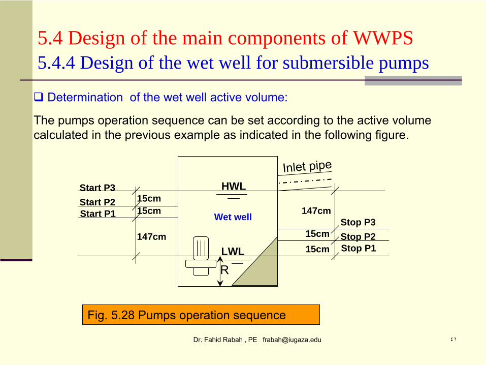
5.4 Design of the main components of WWPS
4TqV
Determination of the wet well active volume:
5.4.4 Design of the wet well for submersible pumps
•
The active volume in the wet well is the volume enclosed between the LWL and the HWL.•
This volume depends on many factors such as the number of pumps, the
capacity of each pump and the raw WW influent flow rate.•
The active volume (V ) when one pump is in operation is calculated from the
following equation:
Where:T: minimum cycle time between pump starts, min.q : the pumping rate of a single pump in operation, m3/minV: active volume for one pump in operation, m3
emptytotimefilltotimeT
Dr. Fahid Rabah , PE [email protected] ٣٩
5.4 Design of the main components of WWPS
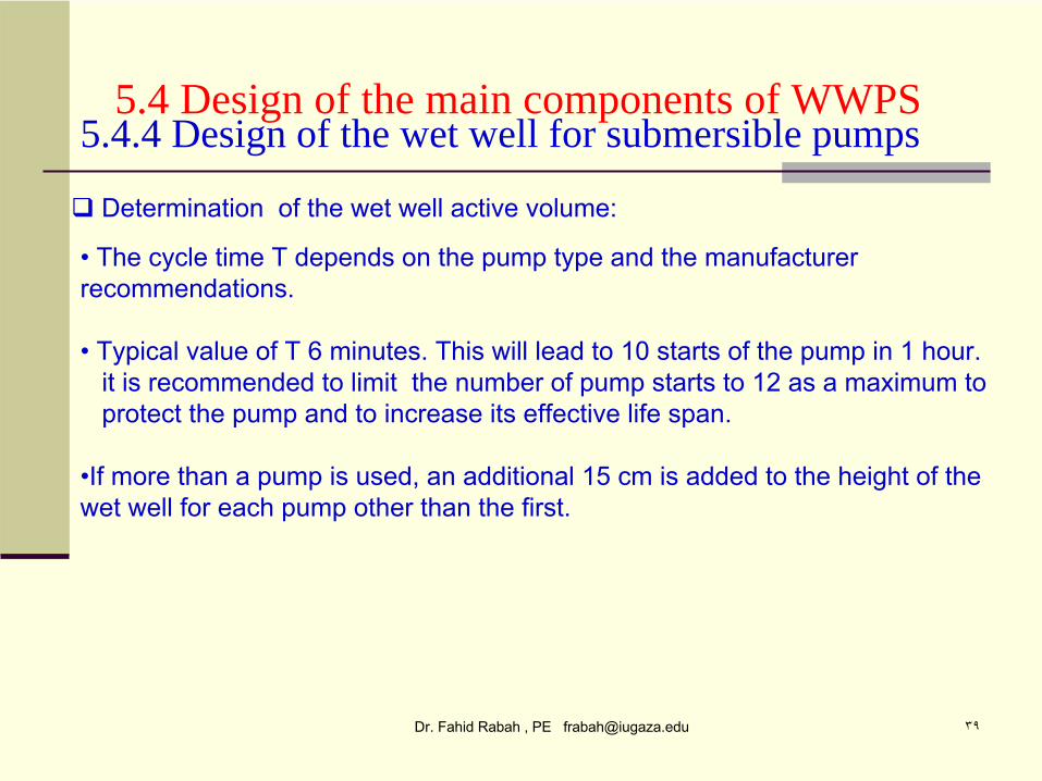
Determination of the wet well active volume:
5.4.4 Design of the wet well for submersible pumps
•
The cycle time T depends on the pump type and the manufacturer recommendations.
• Typical value of T 6 minutes. This will lead to 10 starts of the pump in 1 hour.it is recommended to limit the number of pump starts to 12 as a maximum to protect the pump and to increase its effective life span.
•If more than a pump is used, an additional 15 cm is added
to the height of the wet well for each pump other than the first.
Dr. Fahid Rabah , PE [email protected] ٤٠
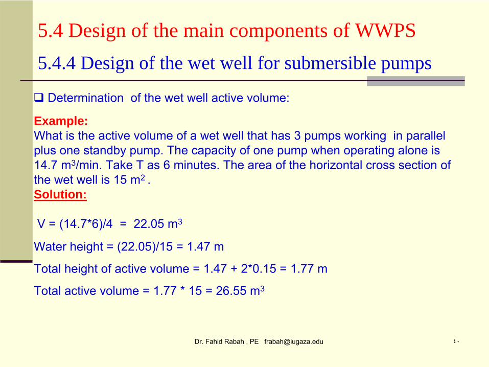
5.4 Design of the main components of WWPS
Determination of the wet well active volume:
5.4.4 Design of the wet well for submersible pumps
Example:What is the active volume of a wet well that has 3 pumps working
in parallel
plus one standby pump. The capacity of one pump when operating alone is 14.7 m3/min. Take T as 6 minutes. The area of the horizontal cross section of the wet well is 15 m2 . Solution:
V = (14.7*6)/4 = 22.05 m3
Water height = (22.05)/15 = 1.47 m
Total height of active volume = 1.47 + 2*0.15 = 1.77 m
Total active volume = 1.77 * 15 = 26.55 m3
Dr. Fahid Rabah , PE [email protected] ٤١
5.4 Design of the main components of WWPS
Determination of the wet well active volume:
5.4.4 Design of the wet well for submersible pumps
The pumps operation sequence can be set according to the active volume calculated in the previous example as indicated in the following
figure.
Inlet pipe
15cm15cm
147cm15cm
Start P3Start P2Start P1 15cm
147cmStop P3Stop P2Stop P1
R
HWL
LWL
Fig. 5.28 Pumps operation sequence
Wet well
Dr. Fahid Rabah , PE [email protected] ٤٢
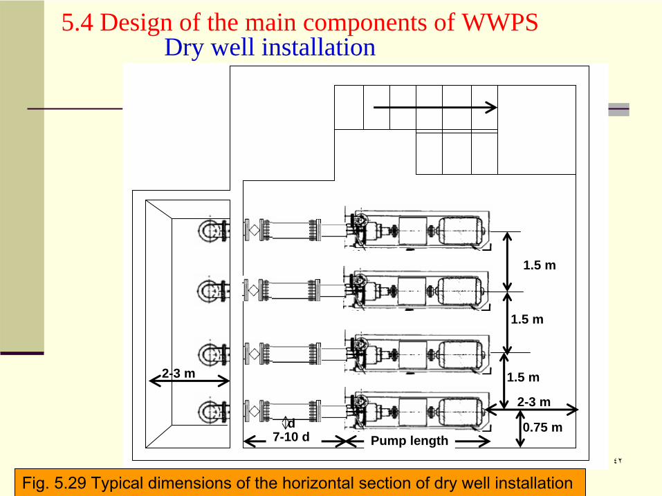
5.4 Design of the main components of WWPS Dry well installation
1.5 m
7-10 d
1.5 m
2-3 m
Pump length
2-3 m
0.75 m
1.5 m
d
Fig. 5.29 Typical dimensions of the horizontal section of dry well installation
Dr. Fahid Rabah , PE [email protected] ٤٣
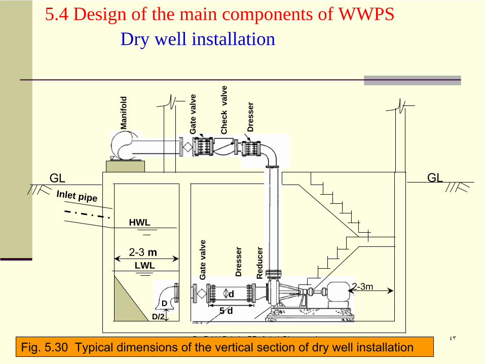
5.4 Design of the main components of WWPS Dry well installation
2-3 m
2-3m
HWL
LWL
Inlet pipe
GLGLG
ate
valv
e
Che
ck v
alve
Dre
sser
Gat
e va
lve
Dre
sser
Red
ucer
DD/2 5 d
d
Man
ifold
Fig. 5.30 Typical dimensions of the vertical section of dry well installation
Dr. Fahid Rabah , PE [email protected] ٤٤
5.4 Design of the main components of WWPS
Figure 5.29 gives the typical dimensions of the the horizontal cross section of the dry and wet well installation.
5.4.5 Design of the wet and dry wells for dry pumps
Figure 5.30 gives the typical dimensions of the the vertical cross section of the dry and wet well installation.
The active volume and pump operation sequence is the same as for the wet wall installation as discussed in the previous example.
Dr. Fahid Rabah , PE [email protected] ٤٥
5.4 Design of the main components of WWPS
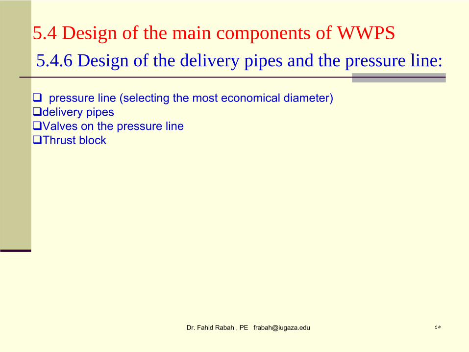
pressure line (selecting the most economical diameter)delivery pipesValves on the pressure lineThrust block
5.4.6 Design of the delivery pipes and the pressure line:
Dr. Fahid Rabah , PE [email protected] ٤٦
5.4 Design of the main components of WWPS
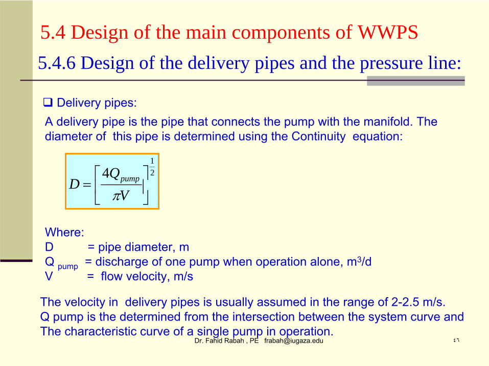
Delivery pipes:
5.4.6 Design of the delivery pipes and the pressure line:
A delivery pipe is the pipe that connects the pump with the manifold. The diameter of this pipe is determined using the Continuity equation:
21
4
VQ
D pump
Where:D = pipe diameter, mQ pump
= discharge of one pump when operation alone, m3/dV = flow velocity, m/s
The velocity in delivery pipes is usually assumed in the range of 2-2.5 m/s.Q pump is the determined from the intersection between the system curve andThe characteristic curve of a single pump in operation.
Dr. Fahid Rabah , PE [email protected] ٤٧
5.4 Design of the main components of WWPS
852.1
87.4
*7.10
CQ
DLhf
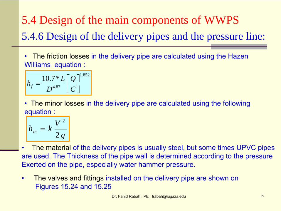
5.4.6 Design of the delivery pipes and the pressure line:
•
The friction losses
in the delivery pipe are calculated using the Hazen Williams equation :
• The material
of the delivery pipes is usually steel, but some times UPVC pipesare used. The Thickness of the pipe wall is determined according
to the pressure
Exerted on the pipe, especially water hammer pressure.
gVkhm 2
2
•
The minor losses
in the delivery pipe are calculated using the following equation :
• The valves and fittings
installed on the delivery pipe are shown on Figures 15.24 and 15.25
Dr. Fahid Rabah , PE [email protected] ٤٨
5.4 Design of the main components of WWPS
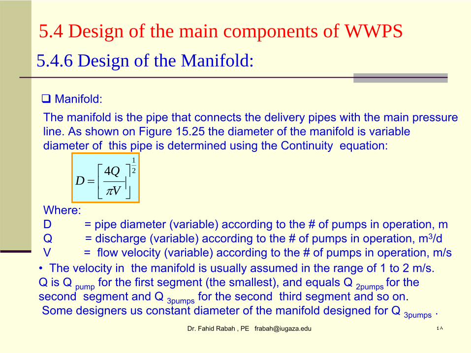
Manifold:
5.4.6 Design of the Manifold:
The manifold is the pipe that connects the delivery pipes with the main pressureline. As shown on Figure 15.25 the diameter of the manifold is variablediameter of this pipe is determined using the Continuity equation:
21
4
VQ
D
Where:D = pipe diameter (variable) according to the # of pumps in operation, mQ = discharge (variable) according to the # of pumps in
operation, m3/d
V = flow velocity (variable) according to the # of pumps in operation, m/s• The velocity in the manifold is usually assumed in the range of 1 to 2 m/s.Q is Q pump
for the first segment (the smallest), and equals Q 2pumps for the second segment and Q 3pumps
for the second third segment
and so on.Some designers us constant diameter of the manifold designed for Q 3pumps
.

Dr. Fahid Rabah , PE [email protected] ٤٩
5.4 Design of the main components of WWPS
852.1
87.4
*7.10
CQ
DLhf
5.4.6 Design of the Manifold :
•
The friction losses
in the manifold pipe
are calculated using the Hazen Williams equation :
• The material
of the manifold pipes
is usually steel, but some times UPVC pipesare used. The Thickness of the pipe wall is determined according
to the pressure
Exerted on the pipe, especially water hammer pressure.
gVkhm 2
2
•
The minor losses
in the manifold pipe
are calculated using the following equation :
Dr. Fahid Rabah , PE [email protected] ٥٠
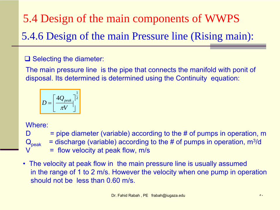
5.4 Design of the main components of WWPS
Selecting the diameter:
5.4.6 Design of the main Pressure line (Rising main):
The main pressure line is the pipe that connects the manifold with ponit
of disposal. Its determined is determined using the Continuity equation:
21
4
VQ
D peak
Where:D = pipe diameter (variable) according to the # of pumps in operation, mQpeak
= discharge (variable) according to the # of pumps in operation, m3/dV = flow velocity at peak flow, m/s
• The velocity at peak flow in the main pressure line is usually assumed in the range of 1 to 2 m/s. However the velocity when one pump in operation should not be less than 0.60 m/s.
Dr. Fahid Rabah , PE [email protected] ٥١
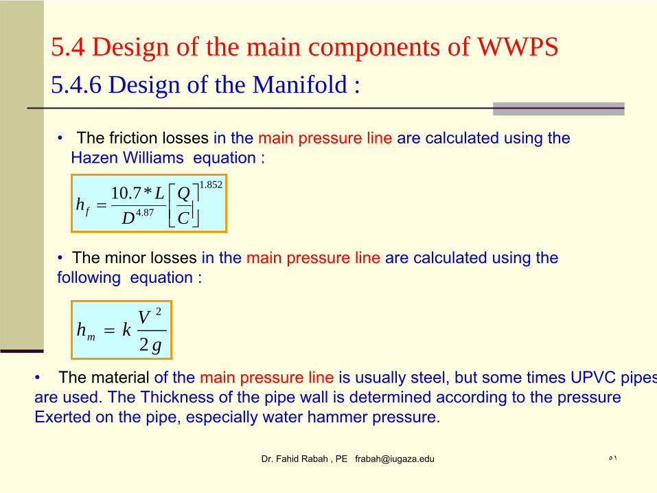
5.4 Design of the main components of WWPS
852.1
87.4
*7.10
CQ
DLhf
5.4.6 Design of the Manifold :
• The friction losses
in the main pressure line
are calculated using the Hazen Williams equation :
• The material
of the main pressure line
is usually steel, but some times UPVC pipesare used. The Thickness of the pipe wall is determined according
to the pressure
Exerted on the pipe, especially water hammer pressure.
gVkhm 2
2
•
The minor losses
in the main pressure line
are calculated using the following equation :
Dr. Fahid Rabah , PE [email protected] ٥٢
5.4 Design of the main components of WWPS
Selecting the most economical diameter for the main pressure line:
5.4.6 Design of the main Pressure line (Rising main):
• As understood from the continuity equation, D is a function of V, so there aremany combinations of D and V that satisfy the equation. Since we
,
as engineers,
look for the most economical design we usually try to use the smallest pipe Diameter, Unfortunately, when D decreases, V increases, consequently the Power needed and the operation cost increases. So we need to select the mostOptimum combination between D and V. This is done using the graph shownbelow (Figure 15.31).• From figure 15.31, when we add up the capital cost and the operation cost weget the concave up curve. The point of inflection indicates the
minimum total
Cost. From this point draw a vertical line that will intersect the X-axis at the mostOptimum diameter. • Notice that the running cost paid along the life span of the pump station and thePressure line so the values on figure 15.31 are the present worth value of the Running cost. The capital cost is paid in one payment at the beginning of the project.
Dr. Fahid Rabah , PE [email protected] ٥٣
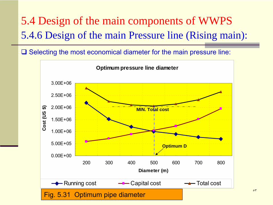
5.4 Design of the main components of WWPS
Selecting the most economical diameter for the main pressure line:
5.4.6 Design of the main Pressure line (Rising main):
Optimum pressure line diameter
0.00E+00
5.00E+05
1.00E+06
1.50E+06
2.00E+06
2.50E+06
3.00E+06
200 300 400 500 600 700 800Diameter (m)
Cost
(US
$)
Running cost Capital cost Total cost
MIN. Total cost
Optimum D
Fig. 5.31 Optimum pipe diameter
Dr. Fahid Rabah , PE [email protected] ٥٤
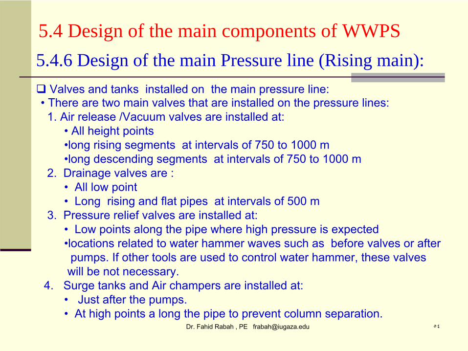
5.4 Design of the main components of WWPS
Valves and tanks installed on the main pressure line:
5.4.6 Design of the main Pressure line (Rising main):
• There are two main valves that are installed on the pressure lines:1. Air release
/Vacuum valves are installed at:
• All height points•long rising segments at intervals of 750 to 1000 m •long descending segments at intervals of 750 to 1000 m
2. Drainage valves are :• All low point• Long rising and flat pipes at intervals of 500 m
3. Pressure relief valves are installed at:• Low points along the pipe where high pressure is expected•locations related to water hammer waves such as before valves or afterpumps. If other tools are used to control water hammer, these valves will be not necessary.
4. Surge tanks and Air champers are installed at:• Just after the pumps.• At high points a long the pipe to prevent column separation.
Dr. Fahid Rabah , PE [email protected] ٥٥
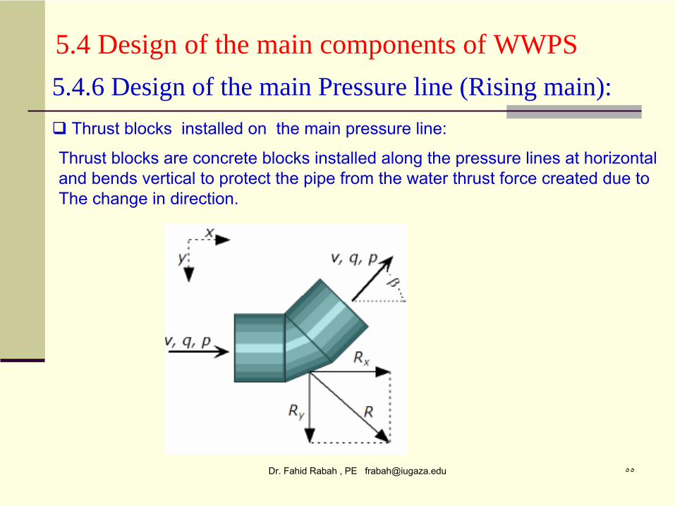
5.4 Design of the main components of WWPS
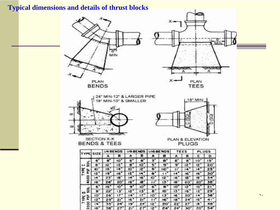
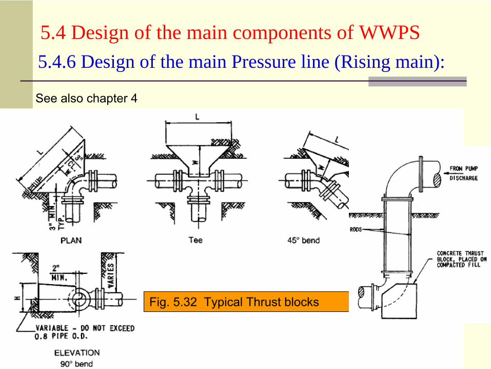
Thrust blocks installed on the main pressure line:
5.4.6 Design of the main Pressure line (Rising main):
Thrust blocks are concrete blocks installed along the pressure lines at horizontal and
bends vertical to protect the pipe from the water thrust force created due to
The change in direction.
Dr. Fahid Rabah , PE [email protected] ٥٦
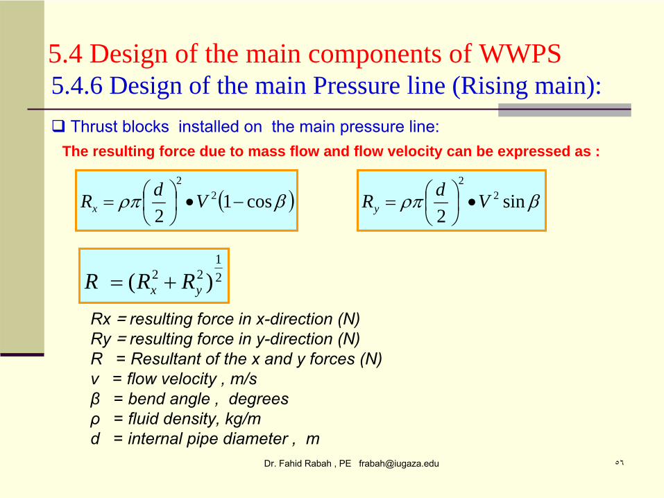
5.4 Design of the main components of WWPS
cos12
22
VdRx sin
22
2
VdRy
Thrust blocks installed on the main pressure line:
5.4.6 Design of the main Pressure line (Rising main):
The resulting force due to mass flow and flow velocity can be expressed as :
21
22 )( yx RRR
Rx = resulting force in x-direction (N)Ry = resulting force in y-direction (N)R = Resultant of the x and y forces (N)v = flow velocity , m/sβ = bend angle , degrees ρ = fluid density, kg/md = internal pipe diameter , m
Dr. Fahid Rabah , PE [email protected] ٥٧
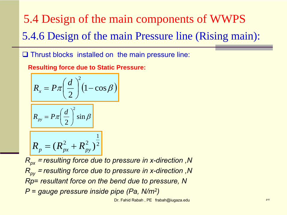
5.4 Design of the main components of WWPS
cos12
2
dPRx
sin2
2
dPRpy
Thrust blocks installed on the main pressure line:
5.4.6 Design of the main Pressure line (Rising main):
Resulting force due to Static Pressure:
21
22 )( pypxp RRR Rpx
= resulting force due to pressure in x-direction ,NRpy
= resulting force due to pressure in x-direction ,NRp= resultant force on the bend due to pressure, NP = gauge pressure inside pipe (Pa, N/m2)
Dr. Fahid Rabah , PE [email protected] ٥٨
5.4 Design of the main components of WWPS5.4.6 Design of the main Pressure line (Rising main):
Fig. 5.32 Typical Thrust blocks
See also chapter 4
Dr. Fahid Rabah , PE [email protected] ٥٩
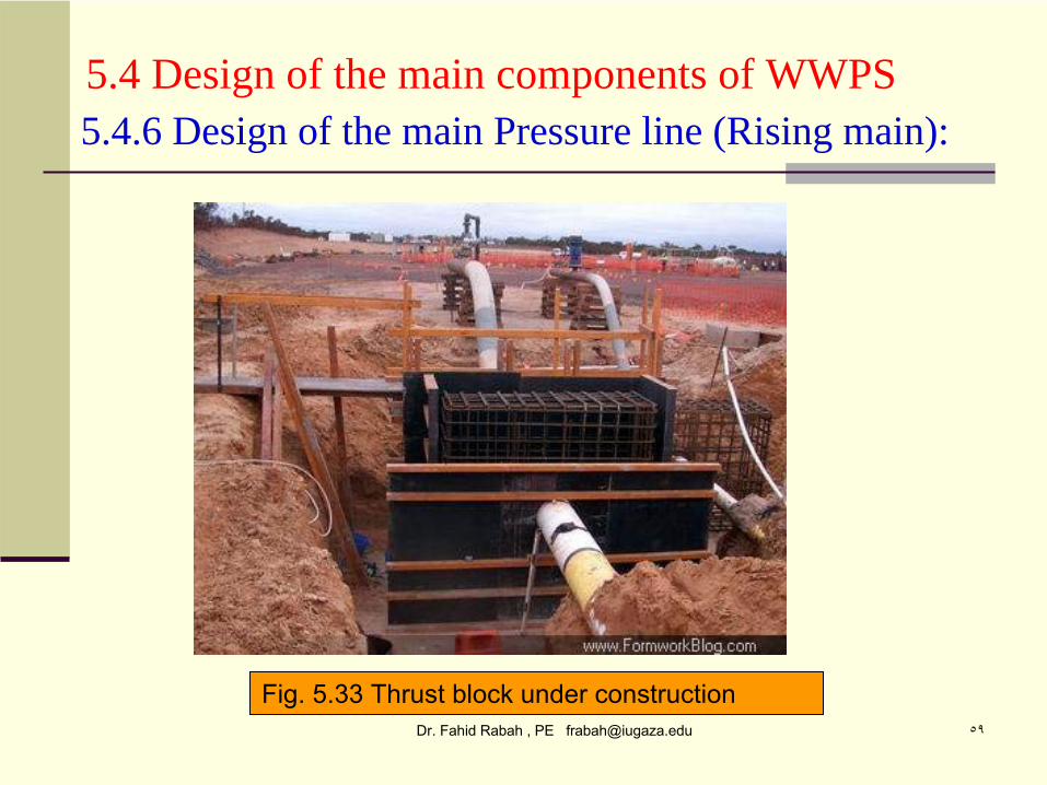
5.4 Design of the main components of WWPS5.4.6 Design of the main Pressure line (Rising main):
Fig. 5.33 Thrust block under construction


![Untitled-1 [ittefaqsteel.com] Report March 2018.pdf · Mian Muhammad Pervaiz Shafi Usman Javed Javed Sadiq Khalid Mustafa Khalida Pervaiz Sumbleen Usman Ayesha Fahid Audit Committee](https://static.fdocuments.net/doc/165x107/5f9ca418acedc82efd2fdd40/untitled-1-report-march-2018pdf-mian-muhammad-pervaiz-shafi-usman-javed-javed.jpg)


