for Hurco Machining Centers mill options... · for Hurco Machining Centers - ii WinMax Mill Options...
226
February 2010 704-0116-410 Revision B WINMAX MILL OPTIONS Dual Screen and Max Consoles for Hurco Machining Centers
-
Upload
trinhduong -
Category
Documents
-
view
231 -
download
3
Transcript of for Hurco Machining Centers mill options... · for Hurco Machining Centers - ii WinMax Mill Options...

February 2010 704-0116-410 Revision B
WINMAX MILLOPTIONS
Dual Screen and Max Consolesfor Hurco Machining Centers

- ii WinMax Mill Options 704-0116-410 WinMax Mill Options
The information in this document is subject to change without notice and does not represent a commitment on the part of Hurco Companies, Inc. (Hurco). The software described in this document is furnished under the License Agreement to customers. It is against the law to copy the software on any medium except as specifically allowed in the license agreement. The purchaser may make copies of the software for backup purposes. No part of this document may be reproduced or transmitted in any form or by any means, electronic or mechanical, including photocopying, for any purpose without the express written permission of the Hurco machine tool owner.
Hurco Manufacturing Company reserves the right to incorporate any modification or improvements in machines and machine specifications which it considers necessary, and does not assume any obligation to make any said changes in machines or equipment previously sold.
Hurco products and services are subject to Hurco’s then current prices, terms, and conditions, which are subject to change without notice.
© 2010 Hurco Companies, Inc. All rights reserved.
Patents: U.S. Patents B14,477,754; 5,453,933; Canadian Patent 1,102,434; Japanese Patents 1,649,006 and 1,375,124; other Patents pending.
Hurco, Max, Ultimax, and WinMax are Registered Trademarks of Hurco Companies, Inc.
AutoCAD, Autodesk, and DXF are registered trademarks of Autodesk, Inc.
MS-DOS, Microsoft, and Windows are registered trademarks of Microsoft Corporation.
Many of the designations used by manufacturers and sellers to distinguish their products are claimed as trademarks. Hurco has listed here all trademarks of which it is aware. For more information about Hurco products and services, contact:
Hurco Companies, Inc. One Technology WayP.O. Box 68180Indianapolis, IN 46268-0180Tel (317) 293-5309 (products)
(317) 298-2635 (service)Fax (317) 328-2812 (service)
For Hurco subsidiary contact information, go to Hurco’s Web site:www.hurco.com

WinMax Mill Options 704-0116-410 Table of Contents -iii
TABLE OF CONTENTS
WinMax Mill Options
Using This Manual . . . . . . . . . . . . . . . . . . . . . . . . . . . . . . . . . . . . . . . . . . . . xiSample Screens . . . . . . . . . . . . . . . . . . . . . . . . . . . . . . . . . . . . . . . . . . . xiUsing the Touchscreen . . . . . . . . . . . . . . . . . . . . . . . . . . . . . . . . . . . . . . xiiiPrinting . . . . . . . . . . . . . . . . . . . . . . . . . . . . . . . . . . . . . . . . . . . . . . . . . xiiiIcons . . . . . . . . . . . . . . . . . . . . . . . . . . . . . . . . . . . . . . . . . . . . . . . . . . xiii
Using and Printing the Help . . . . . . . . . . . . . . . . . . . . . . . . . . . . . . . . . . . . . . xivUsing the On-screen Help . . . . . . . . . . . . . . . . . . . . . . . . . . . . . . . . . . . . xivPrinting the Help . . . . . . . . . . . . . . . . . . . . . . . . . . . . . . . . . . . . . . . . . . xv
3D Mold . . . . . . . . . . . . . . . . . . . . . . . . . . . . . . . . . . . . . . . . . . . . . . . . . . .1 - 13D Mold Parameters . . . . . . . . . . . . . . . . . . . . . . . . . . . . . . . . . . . . . . . .1 - 23D Mold Contour . . . . . . . . . . . . . . . . . . . . . . . . . . . . . . . . . . . . . . . . . .1 - 93D Mold Line . . . . . . . . . . . . . . . . . . . . . . . . . . . . . . . . . . . . . . . . . . . . .1 - 103D Mold Arc . . . . . . . . . . . . . . . . . . . . . . . . . . . . . . . . . . . . . . . . . . . . . .1 - 113D Mold Blend Arc . . . . . . . . . . . . . . . . . . . . . . . . . . . . . . . . . . . . . . . . .1 - 12Roughing and Finishing Tools . . . . . . . . . . . . . . . . . . . . . . . . . . . . . . . . . .1 - 13Roughing and Finishing Passes . . . . . . . . . . . . . . . . . . . . . . . . . . . . . . . . .1 - 17
Custom Drill . . . . . . . . . . . . . . . . . . . . . . . . . . . . . . . . . . . . . . . . . . . . . . . .2 - 1Tool Tab . . . . . . . . . . . . . . . . . . . . . . . . . . . . . . . . . . . . . . . . . . . . . . . .2 - 1Entry Tab . . . . . . . . . . . . . . . . . . . . . . . . . . . . . . . . . . . . . . . . . . . . . . .2 - 3Break Out Tab . . . . . . . . . . . . . . . . . . . . . . . . . . . . . . . . . . . . . . . . . . . .2 - 4Bottom Tab . . . . . . . . . . . . . . . . . . . . . . . . . . . . . . . . . . . . . . . . . . . . . .2 - 5Re-entry Tab . . . . . . . . . . . . . . . . . . . . . . . . . . . . . . . . . . . . . . . . . . . . .2 - 6Out Tab . . . . . . . . . . . . . . . . . . . . . . . . . . . . . . . . . . . . . . . . . . . . . . . . .2 - 7Retract Tab . . . . . . . . . . . . . . . . . . . . . . . . . . . . . . . . . . . . . . . . . . . . . .2 - 8
DXF Option . . . . . . . . . . . . . . . . . . . . . . . . . . . . . . . . . . . . . . . . . . . . . . . . .3 - 1DXF Overview . . . . . . . . . . . . . . . . . . . . . . . . . . . . . . . . . . . . . . . . . . . .3 - 2DXF Build Data Block . . . . . . . . . . . . . . . . . . . . . . . . . . . . . . . . . . . . . . .3 - 3DXF Parameters . . . . . . . . . . . . . . . . . . . . . . . . . . . . . . . . . . . . . . . . . . .3 - 4
Zoom Window . . . . . . . . . . . . . . . . . . . . . . . . . . . . . . . . . . . . . . . . .3 - 5Edit Drawing . . . . . . . . . . . . . . . . . . . . . . . . . . . . . . . . . . . . . . . . . . . . .3 - 5
DXF Edit Modify - Arc . . . . . . . . . . . . . . . . . . . . . . . . . . . . . . . . . . . . .3 - 8DXF Edit Modify - Line . . . . . . . . . . . . . . . . . . . . . . . . . . . . . . . . . . . .3 - 8DXF Edit Modify - Point . . . . . . . . . . . . . . . . . . . . . . . . . . . . . . . . . . . .3 - 8
DXF Layers . . . . . . . . . . . . . . . . . . . . . . . . . . . . . . . . . . . . . . . . . . . . . .3 - 9
HD3 Serial Number Lettering . . . . . . . . . . . . . . . . . . . . . . . . . . . . . . . . . . . .4 - 1Text tab . . . . . . . . . . . . . . . . . . . . . . . . . . . . . . . . . . . . . . . . . . . . . . . .4 - 1Orientation tab . . . . . . . . . . . . . . . . . . . . . . . . . . . . . . . . . . . . . . . . . . . .4 - 3Format tab . . . . . . . . . . . . . . . . . . . . . . . . . . . . . . . . . . . . . . . . . . . . . . .4 - 4
Helical Plunge Option . . . . . . . . . . . . . . . . . . . . . . . . . . . . . . . . . . . . . . . . . .5 - 1Helical Plunge Milling Parameter Fields . . . . . . . . . . . . . . . . . . . . . . . . . . .5 - 2Helical Plunge (Inside/Outside) for Mill Frames, Mill Circles and Ellipses . . . .5 - 3Helical Plunge with UltiPocket . . . . . . . . . . . . . . . . . . . . . . . . . . . . . . . . . .5 - 3

- iv Table of Contents 704-0116-410 Machine WinMax Mill Options
Helical Plunge with Operator Specified Location . . . . . . . . . . . . . . . . . . . . .5 - 3Helical Plunge in the Center of a Pocket . . . . . . . . . . . . . . . . . . . . . . . . . . .5 - 3Helical Plunge with Outward Pocketing . . . . . . . . . . . . . . . . . . . . . . . . . . .5 - 4Helical Plunge of Mill Frame Inside with No Pecking and Blend Offset . . . . . .5 - 4Helical Plunging of Mill Frame Inside with Pecking and Straight Plunge Finish Pass and Blend Offset . . . . . . . . . . . . . . . . . . . . . . . . . . . . . . . . . . . . . . . . . . . . . .5 - 5Helical Plunge with Lines and Arcs . . . . . . . . . . . . . . . . . . . . . . . . . . . . . .5 - 7
Helical Plunge with 3-D Part Programming Option . . . . . . . . . . . . . . . . .5 - 7
Rotary . . . . . . . . . . . . . . . . . . . . . . . . . . . . . . . . . . . . . . . . . . . . . . . . . . . .6 - 1Rotary Overview . . . . . . . . . . . . . . . . . . . . . . . . . . . . . . . . . . . . . . . . . . .6 - 2
Rotary Axis . . . . . . . . . . . . . . . . . . . . . . . . . . . . . . . . . . . . . . . . . . . .6 - 3Tilt Axis . . . . . . . . . . . . . . . . . . . . . . . . . . . . . . . . . . . . . . . . . . . . . .6 - 3Configuration of Hurco Machining Centers . . . . . . . . . . . . . . . . . . . . . .6 - 3Transform Plane . . . . . . . . . . . . . . . . . . . . . . . . . . . . . . . . . . . . . . . .6 - 5
Rotary Part Setup . . . . . . . . . . . . . . . . . . . . . . . . . . . . . . . . . . . . . . . . . .6 - 8Rotary Centerline . . . . . . . . . . . . . . . . . . . . . . . . . . . . . . . . . . . . . . .6 - 8
Rotary Part Programming . . . . . . . . . . . . . . . . . . . . . . . . . . . . . . . . . . . .6 - 10Rotary New Block . . . . . . . . . . . . . . . . . . . . . . . . . . . . . . . . . . . . . . .6 - 10Rotary Position Block . . . . . . . . . . . . . . . . . . . . . . . . . . . . . . . . . . . . .6 - 11Rotary Milling New Block . . . . . . . . . . . . . . . . . . . . . . . . . . . . . . . . . .6 - 12Rotary Patterns . . . . . . . . . . . . . . . . . . . . . . . . . . . . . . . . . . . . . . . . .6 - 12Rotary Parameters . . . . . . . . . . . . . . . . . . . . . . . . . . . . . . . . . . . . . . .6 - 13
Rotary A and Rotary A Tilt B Configuration . . . . . . . . . . . . . . . . . . . . . . . .6 - 14Rotary Position . . . . . . . . . . . . . . . . . . . . . . . . . . . . . . . . . . . . . . . . .6 - 14Rotary Lines and Arcs . . . . . . . . . . . . . . . . . . . . . . . . . . . . . . . . . . . .6 - 14Rotary Circle . . . . . . . . . . . . . . . . . . . . . . . . . . . . . . . . . . . . . . . . . . .6 - 15Rotary Frame . . . . . . . . . . . . . . . . . . . . . . . . . . . . . . . . . . . . . . . . . .6 - 16Rotary Patterns . . . . . . . . . . . . . . . . . . . . . . . . . . . . . . . . . . . . . . . . .6 - 16Rotary Parameters . . . . . . . . . . . . . . . . . . . . . . . . . . . . . . . . . . . . . . .6 - 18
Tilt A Rotary C Configuration . . . . . . . . . . . . . . . . . . . . . . . . . . . . . . . . . .6 - 19Rotary Position . . . . . . . . . . . . . . . . . . . . . . . . . . . . . . . . . . . . . . . . .6 - 19Rotary Lines and Arcs . . . . . . . . . . . . . . . . . . . . . . . . . . . . . . . . . . . .6 - 19Rotary Circle . . . . . . . . . . . . . . . . . . . . . . . . . . . . . . . . . . . . . . . . . . .6 - 20Rotary Frame . . . . . . . . . . . . . . . . . . . . . . . . . . . . . . . . . . . . . . . . . .6 - 21Rotary Patterns . . . . . . . . . . . . . . . . . . . . . . . . . . . . . . . . . . . . . . . . .6 - 21Rotary Parameters . . . . . . . . . . . . . . . . . . . . . . . . . . . . . . . . . . . . . . .6 - 23
Rotary B Configuration . . . . . . . . . . . . . . . . . . . . . . . . . . . . . . . . . . . . . .6 - 24Rotary Position . . . . . . . . . . . . . . . . . . . . . . . . . . . . . . . . . . . . . . . . .6 - 24Rotary Milling . . . . . . . . . . . . . . . . . . . . . . . . . . . . . . . . . . . . . . . . . .6 - 24Rotary Patterns . . . . . . . . . . . . . . . . . . . . . . . . . . . . . . . . . . . . . . . . .6 - 24Rotary Parameters . . . . . . . . . . . . . . . . . . . . . . . . . . . . . . . . . . . . . . .6 - 26
Tilt B Rotary C Configuration . . . . . . . . . . . . . . . . . . . . . . . . . . . . . . . . . .6 - 27Rotary Position . . . . . . . . . . . . . . . . . . . . . . . . . . . . . . . . . . . . . . . . .6 - 27Rotary Lines and Arcs . . . . . . . . . . . . . . . . . . . . . . . . . . . . . . . . . . . .6 - 27Rotary Circle . . . . . . . . . . . . . . . . . . . . . . . . . . . . . . . . . . . . . . . . . . .6 - 28Rotary Frame . . . . . . . . . . . . . . . . . . . . . . . . . . . . . . . . . . . . . . . . . .6 - 29Rotary Patterns . . . . . . . . . . . . . . . . . . . . . . . . . . . . . . . . . . . . . . . . .6 - 29Rotary Parameters . . . . . . . . . . . . . . . . . . . . . . . . . . . . . . . . . . . . . . .6 - 31
Universal Rotary Configuration . . . . . . . . . . . . . . . . . . . . . . . . . . . . . . . . .6 - 32Rotary Position Block . . . . . . . . . . . . . . . . . . . . . . . . . . . . . . . . . . . . .6 - 32Rotary Lines and Arcs . . . . . . . . . . . . . . . . . . . . . . . . . . . . . . . . . . . .6 - 33Rotary Circle . . . . . . . . . . . . . . . . . . . . . . . . . . . . . . . . . . . . . . . . . . .6 - 34Rotary Frame . . . . . . . . . . . . . . . . . . . . . . . . . . . . . . . . . . . . . . . . . .6 - 35Rotary True Type Font . . . . . . . . . . . . . . . . . . . . . . . . . . . . . . . . . . . .6 - 35

WinMax Mill Options 704-0116-410 Table of Contents -v
Rotary Patterns . . . . . . . . . . . . . . . . . . . . . . . . . . . . . . . . . . . . . . . . .6 - 37Calculating X- and Z-Axis Positions After a Tilt-Axis Move . . . . . . . . . . . . . .6 - 41
Part Zero Calibrated at Zero Degree Vertical . . . . . . . . . . . . . . . . . . . . .6 - 41Part Zero Calibrated at Zero Degree Horizontal . . . . . . . . . . . . . . . . . . .6 - 42
Example Programs . . . . . . . . . . . . . . . . . . . . . . . . . . . . . . . . . . . . . . . . .6 - 43Rotary Programming Examples . . . . . . . . . . . . . . . . . . . . . . . . . . . . . .6 - 43Tilt-Axis Programming Examples . . . . . . . . . . . . . . . . . . . . . . . . . . . . .6 - 51Transform Plane Example Programs . . . . . . . . . . . . . . . . . . . . . . . . . . .6 - 54
Mill Polygon . . . . . . . . . . . . . . . . . . . . . . . . . . . . . . . . . . . . . . . . . . . . . . . .7 - 1
Probing Option . . . . . . . . . . . . . . . . . . . . . . . . . . . . . . . . . . . . . . . . . . . . . .8 - 1Part Probe Deflection . . . . . . . . . . . . . . . . . . . . . . . . . . . . . . . . . . . . . . .8 - 2Part Probe Working Envelope . . . . . . . . . . . . . . . . . . . . . . . . . . . . . . . . . .8 - 2Tool Probe Setup Parameters . . . . . . . . . . . . . . . . . . . . . . . . . . . . . . . . . .8 - 2Part Probing Parameters . . . . . . . . . . . . . . . . . . . . . . . . . . . . . . . . . . . . .8 - 5
Tool Probe Calibration . . . . . . . . . . . . . . . . . . . . . . . . . . . . . . . . . . . .8 - 6Touch Tool Probe Calibration . . . . . . . . . . . . . . . . . . . . . . . . . . . . . . . .8 - 7Touch Tool and Part Probe Calibration . . . . . . . . . . . . . . . . . . . . . . . . .8 - 8Laser Beam Calibration . . . . . . . . . . . . . . . . . . . . . . . . . . . . . . . . . . .8 - 9Tool Probe Deflection Offset Calibration . . . . . . . . . . . . . . . . . . . . . . . .8 - 11Part Probe Calibration . . . . . . . . . . . . . . . . . . . . . . . . . . . . . . . . . . . .8 - 12Part Probe Deflection Offset Calibration . . . . . . . . . . . . . . . . . . . . . . . .8 - 13
Tool Setup Probing Softkeys . . . . . . . . . . . . . . . . . . . . . . . . . . . . . . . . . .8 - 15Tool Setup Probing Fields . . . . . . . . . . . . . . . . . . . . . . . . . . . . . . . . . . . .8 - 16Probe Part Setup . . . . . . . . . . . . . . . . . . . . . . . . . . . . . . . . . . . . . . . . . .8 - 17Conversational Part Probing Cycles . . . . . . . . . . . . . . . . . . . . . . . . . . . . . .8 - 19
Part Setup Screen . . . . . . . . . . . . . . . . . . . . . . . . . . . . . . . . . . . . . . .8 - 19Part Zero Storage Cycle . . . . . . . . . . . . . . . . . . . . . . . . . . . . . . . . . . . . .8 - 20
Manual Mode Part Setup Probing Cycles . . . . . . . . . . . . . . . . . . . . . . . .8 - 20Manual Mode Part Skew Probing Cycles . . . . . . . . . . . . . . . . . . . . . . . .8 - 21Automatic Mode . . . . . . . . . . . . . . . . . . . . . . . . . . . . . . . . . . . . . . . .8 - 23
Probe Part Setup Data Block . . . . . . . . . . . . . . . . . . . . . . . . . . . . . . . . . .8 - 23Probe Part Setup Fields . . . . . . . . . . . . . . . . . . . . . . . . . . . . . . . . . . .8 - 23Automatic Part Zero Cycles . . . . . . . . . . . . . . . . . . . . . . . . . . . . . . . . .8 - 24Automatic Skew Cycles . . . . . . . . . . . . . . . . . . . . . . . . . . . . . . . . . . .8 - 25
Probe Part Setup Data Block Execution . . . . . . . . . . . . . . . . . . . . . . . . . . .8 - 26Part Inspection Cycles . . . . . . . . . . . . . . . . . . . . . . . . . . . . . . . . . . . .8 - 26Part Inspection Programming . . . . . . . . . . . . . . . . . . . . . . . . . . . . . . .8 - 28Probe Tool Monitoring . . . . . . . . . . . . . . . . . . . . . . . . . . . . . . . . . . . .8 - 28Manual Tool Probing Cycles . . . . . . . . . . . . . . . . . . . . . . . . . . . . . . . . .8 - 30
Tool Wear Detection Data Block . . . . . . . . . . . . . . . . . . . . . . . . . . . . . . . .8 - 32Probing Cycles . . . . . . . . . . . . . . . . . . . . . . . . . . . . . . . . . . . . . . . . . . . .8 - 33
Part Setup Probing Cycles . . . . . . . . . . . . . . . . . . . . . . . . . . . . . . . . . .8 - 33Part Skew Probing Cycles . . . . . . . . . . . . . . . . . . . . . . . . . . . . . . . . . .8 - 34Edge Cycle . . . . . . . . . . . . . . . . . . . . . . . . . . . . . . . . . . . . . . . . . . . .8 - 35Hole or Circle Pocket Cycle . . . . . . . . . . . . . . . . . . . . . . . . . . . . . . . . .8 - 38Cylinder Cycle . . . . . . . . . . . . . . . . . . . . . . . . . . . . . . . . . . . . . . . . . .8 - 40Rectangular Pocket Inside Cycle . . . . . . . . . . . . . . . . . . . . . . . . . . . . .8 - 42Rectangular Solid Outside Cycle . . . . . . . . . . . . . . . . . . . . . . . . . . . . .8 - 44Plane Intersection (Non-Rectangular Corner) Cycle . . . . . . . . . . . . . . . .8 - 46Edge Skew Cycle . . . . . . . . . . . . . . . . . . . . . . . . . . . . . . . . . . . . . . . .8 - 48Hole or Circle Pocket Skew Cycle . . . . . . . . . . . . . . . . . . . . . . . . . . . . .8 - 49Cylinder Skew Cycle . . . . . . . . . . . . . . . . . . . . . . . . . . . . . . . . . . . . . .8 - 50Rectangular Pocket Skew Cycle . . . . . . . . . . . . . . . . . . . . . . . . . . . . . .8 - 51

- vi Table of Contents 704-0116-410 Machine WinMax Mill Options
Rectangular Solid Skew Cycle . . . . . . . . . . . . . . . . . . . . . . . . . . . . . . .8 - 52
Mill Slot . . . . . . . . . . . . . . . . . . . . . . . . . . . . . . . . . . . . . . . . . . . . . . . . . . .9 - 1Start tab . . . . . . . . . . . . . . . . . . . . . . . . . . . . . . . . . . . . . . . . . . . . . . . .9 - 2Geometry tab . . . . . . . . . . . . . . . . . . . . . . . . . . . . . . . . . . . . . . . . . . . . .9 - 3Caps tab . . . . . . . . . . . . . . . . . . . . . . . . . . . . . . . . . . . . . . . . . . . . . . . .9 - 4
Thread Mill . . . . . . . . . . . . . . . . . . . . . . . . . . . . . . . . . . . . . . . . . . . . . . . . .10 - 1
Tool Change Optimization . . . . . . . . . . . . . . . . . . . . . . . . . . . . . . . . . . . . . . .11 - 1
Tool Fixture (TPS) Option . . . . . . . . . . . . . . . . . . . . . . . . . . . . . . . . . . . . . . .12 - 1Tool Fixture Overview . . . . . . . . . . . . . . . . . . . . . . . . . . . . . . . . . . . . . . .12 - 2Automatic Tool Removal Using TPS . . . . . . . . . . . . . . . . . . . . . . . . . . . . . .12 - 3Automatic Tool Change Using TPS . . . . . . . . . . . . . . . . . . . . . . . . . . . . . .12 - 4Bypass TPS in an Automatic Tool Change . . . . . . . . . . . . . . . . . . . . . . . . .12 - 5
UltiMotion . . . . . . . . . . . . . . . . . . . . . . . . . . . . . . . . . . . . . . . . . . . . . . . . . .13 - 1
UltiNet . . . . . . . . . . . . . . . . . . . . . . . . . . . . . . . . . . . . . . . . . . . . . . . . . . . .14 - 1UltiNet FTP Client . . . . . . . . . . . . . . . . . . . . . . . . . . . . . . . . . . . . . . . . . .14 - 2UltiNet FTP Server . . . . . . . . . . . . . . . . . . . . . . . . . . . . . . . . . . . . . . . . .14 - 2
FTP Server Settings . . . . . . . . . . . . . . . . . . . . . . . . . . . . . . . . . . . . . .14 - 3
UltiPockets Option . . . . . . . . . . . . . . . . . . . . . . . . . . . . . . . . . . . . . . . . . . . .15 - 1Pocket Boundary . . . . . . . . . . . . . . . . . . . . . . . . . . . . . . . . . . . . . . . . . .15 - 2
Spiral Outward - No Islands . . . . . . . . . . . . . . . . . . . . . . . . . . . . . . . .15 - 2Spiral Inward . . . . . . . . . . . . . . . . . . . . . . . . . . . . . . . . . . . . . . . . . .15 - 2Programming Islands . . . . . . . . . . . . . . . . . . . . . . . . . . . . . . . . . . . . .15 - 2Mill Contours . . . . . . . . . . . . . . . . . . . . . . . . . . . . . . . . . . . . . . . . . . .15 - 3Mill Frame . . . . . . . . . . . . . . . . . . . . . . . . . . . . . . . . . . . . . . . . . . . .15 - 3Mill Circle . . . . . . . . . . . . . . . . . . . . . . . . . . . . . . . . . . . . . . . . . . . . .15 - 3Pattern . . . . . . . . . . . . . . . . . . . . . . . . . . . . . . . . . . . . . . . . . . . . . . .15 - 3
Helical Plunge with UltiPocket Option . . . . . . . . . . . . . . . . . . . . . . . . . . . .15 - 4Helical Plunge Using Operator Specify Pocket Start . . . . . . . . . . . . . . . . . . .15 - 5
Record of Changes . . . . . . . . . . . . . . . . . . . . . . . . . . . . . . . . . . . . . . . . . . . . 1
Index . . . . . . . . . . . . . . . . . . . . . . . . . . . . . . . . . . . . . . . . . . . . . . . . . . . . . 1

WinMax Mill Options 704-0116-410 List of Figures -vii
LIST OF FIGURES
Figure 1–1. Increased Radius . . . . . . . . . . . . . . . . . . . . . . . . . . . . . . . . . . . . 1 - 3Figure 1–2. Zero Radius . . . . . . . . . . . . . . . . . . . . . . . . . . . . . . . . . . . . . . . 1 - 3Figure 1–3. Convex Contour Below the Part Surface . . . . . . . . . . . . . . . . . . . . 1 - 4Figure 1–4. Counterclockwise and Clockwise Motion . . . . . . . . . . . . . . . . . . . . 1 - 4Figure 1–5. Y Start and Y End Fields (XZ Translated in Y) . . . . . . . . . . . . . . . . 1 - 5Figure 1–6. Bidirectional field . . . . . . . . . . . . . . . . . . . . . . . . . . . . . . . . . . . . 1 - 6Figure 1–7. Step Size . . . . . . . . . . . . . . . . . . . . . . . . . . . . . . . . . . . . . . . . . 1 - 7Figure 1–8. Peck Depth . . . . . . . . . . . . . . . . . . . . . . . . . . . . . . . . . . . . . . . . 1 - 7Figure 1–9. Stock Allowance . . . . . . . . . . . . . . . . . . . . . . . . . . . . . . . . . . . . 1 - 8Figure 1–10.Flat End Mill on a Contour . . . . . . . . . . . . . . . . . . . . . . . . . . . . . . 1 - 13Figure 1–11.Ball-Nosed End Mill on a Contour . . . . . . . . . . . . . . . . . . . . . . . . . 1 - 14Figure 1–12.Flat End Mill . . . . . . . . . . . . . . . . . . . . . . . . . . . . . . . . . . . . . . . 1 - 15Figure 1–13. Ball-Nosed End Mill . . . . . . . . . . . . . . . . . . . . . . . . . . . . . . . . . 1 - 16Figure 1–14.Roughing and Finishing Passes . . . . . . . . . . . . . . . . . . . . . . . . . . 1 - 17
Figure 2–1. Custom Drill Tool tab . . . . . . . . . . . . . . . . . . . . . . . . . . . . . . . . . 2 - 1Figure 2–2. Custom Drill Entry tab . . . . . . . . . . . . . . . . . . . . . . . . . . . . . . . . 2 - 3Figure 2–3. Custom Drill Break Out tab . . . . . . . . . . . . . . . . . . . . . . . . . . . . . 2 - 4Figure 2–4. Custom Drill Bottom tab . . . . . . . . . . . . . . . . . . . . . . . . . . . . . . . 2 - 5Figure 2–5. Custom Drill Re-entry tab . . . . . . . . . . . . . . . . . . . . . . . . . . . . . . 2 - 6Figure 2–6. Custom Drill Out tab . . . . . . . . . . . . . . . . . . . . . . . . . . . . . . . . . 2 - 7Figure 2–7. Custom Drill Retract tab . . . . . . . . . . . . . . . . . . . . . . . . . . . . . . . 2 - 8
Figure 3–1. Extended Lines and Arcs . . . . . . . . . . . . . . . . . . . . . . . . . . . . . . . 3 - 6Figure 3–2. Joined Lines and Arcs . . . . . . . . . . . . . . . . . . . . . . . . . . . . . . . . . 3 - 7
Figure 4–1. HD3 Serial Number Lettering Text tab . . . . . . . . . . . . . . . . . . . . . 4 - 2Figure 4–2. X Reference and Y Reference locations . . . . . . . . . . . . . . . . . . . . . 4 - 4
Figure 5–1. Helical Plunge with No Pecking and Blend Offset (Isometric View) . . 5 - 4Figure 5–2. First Peck (Isometric View) . . . . . . . . . . . . . . . . . . . . . . . . . . . . . 5 - 5Figure 5–3. Second Peck (Isometric View) . . . . . . . . . . . . . . . . . . . . . . . . . . . 5 - 6Figure 5–4. Finish Pass (Isometric View) . . . . . . . . . . . . . . . . . . . . . . . . . . . . 5 - 6Figure 5–5. Helical Plunging with Lines/Arcs (Isometric View) . . . . . . . . . . . . . 5 - 7
Figure 6–1. Axes Movement . . . . . . . . . . . . . . . . . . . . . . . . . . . . . . . . . . . . . 6 - 2Figure 6–2. Rotary Cemterline . . . . . . . . . . . . . . . . . . . . . . . . . . . . . . . . . . . 6 - 9Figure 6–3. Rotary Centerline . . . . . . . . . . . . . . . . . . . . . . . . . . . . . . . . . . . 6 - 9Figure 6–4. Y Mapping . . . . . . . . . . . . . . . . . . . . . . . . . . . . . . . . . . . . . . . . . 6 - 36Figure 6–5. Vertical Tilt-Axis Example . . . . . . . . . . . . . . . . . . . . . . . . . . . . . . 6 - 41Figure 6–6. Horizontal Tilt-Axis Example . . . . . . . . . . . . . . . . . . . . . . . . . . . . 6 - 42Figure 6–7. Rotary Mill Frame Part Drawing (cylinder shown for reference) . . . . 6 - 43Figure 6–8. Threading Part Drawing (cylinder shown for reference) . . . . . . . . . 6 - 44Figure 6–9. Single Hole Part Drawing (cylinder shown for reference) . . . . . . . . 6 - 46Figure 6–10.Rotary Pattern Loop Part Drawing (cylinder shown for reference) . . 6 - 47Figure 6–11.4-axis Part Created Using Transform Plane . . . . . . . . . . . . . . . . . . 6 - 48Figure 6–12.Bolt Holes on Tilted Cylindrical Part . . . . . . . . . . . . . . . . . . . . . . . 6 - 51Figure 6–13.Cylindrical Part Tilted 45° Between Holes . . . . . . . . . . . . . . . . . . . 6 - 52

-viii List of Figures 704-0116-410 WinMax Mill Options
Figure 6–14.Same Part Zero for Transformed Plane, VMX42 SR Machine . . . . . . 6 - 54Figure 6–15.Part Created on VMX42SR Machine, Using Transform Plane . . . . . . 6 - 56
Figure 7–1. Mill Polygon screen . . . . . . . . . . . . . . . . . . . . . . . . . . . . . . . . . . 7 - 1
Figure 8–1. Laser Tool Calibration Calculations . . . . . . . . . . . . . . . . . . . . . . . . 8 - 9Figure 8–2. Laser Tool Calibration Cycle . . . . . . . . . . . . . . . . . . . . . . . . . . . . 8 - 10Figure 8–3. Skewed work piece with Preset Y offset . . . . . . . . . . . . . . . . . . . . 8 - 22Figure 8–4. Edge Cycle probing in +X direction—Top View . . . . . . . . . . . . . . . . 8 - 35Figure 8–5. Edge Cycle probing in +Y direction—Top View . . . . . . . . . . . . . . . . 8 - 35Figure 8–6. Edge Cycle probing in +Z direction—Side View . . . . . . . . . . . . . . . 8 - 36Figure 8–7. Edge Cycle probing in X direction—Side View . . . . . . . . . . . . . . . . 8 - 36Figure 8–8. Part Probe movement during a Hole or CirclePocket cycle . . . . . . . . 8 - 38Figure 8–9. Part Probe movement during Cylinder cycle . . . . . . . . . . . . . . . . . 8 - 40Figure 8–10.Part Probe movement during Rectangular Pocket cycle . . . . . . . . . . 8 - 42Figure 8–11.Part Probe movement during Rectangular Solid cycle . . . . . . . . . . . 8 - 44Figure 8–12.Part Probe movement with Solid or Pocket geometry . . . . . . . . . . . 8 - 46
Figure 9–1. Line Slot rotated 90° . . . . . . . . . . . . . . . . . . . . . . . . . . . . . . . . . 9 - 1Figure 9–2. Mill Slot Start tab . . . . . . . . . . . . . . . . . . . . . . . . . . . . . . . . . . . 9 - 2Figure 9–3. Mill Slot Geometry tab for a Line slot . . . . . . . . . . . . . . . . . . . . . . 9 - 3Figure 9–4. Mill Slot Geometry tab for an Arc slot . . . . . . . . . . . . . . . . . . . . . . 9 - 3Figure 9–5. Mill Slot Caps tab . . . . . . . . . . . . . . . . . . . . . . . . . . . . . . . . . . . . 9 - 4Figure 9–6. Append Arc Start Cap and Line End Cap . . . . . . . . . . . . . . . . . . . . 9 - 5Figure 9–7. Include Arc Start Cap and Line End Cap . . . . . . . . . . . . . . . . . . . . 9 - 5
Figure 10–1.Tool movement when Thread Direction is down . . . . . . . . . . . . . . . 10 - 1Figure 10–2.Tool movement when Thread Direction is up . . . . . . . . . . . . . . . . . 10 - 2Figure 10–3.Mill Thread screen . . . . . . . . . . . . . . . . . . . . . . . . . . . . . . . . . . . 10 - 2
Figure 11–1.Tool Change Optimization On block . . . . . . . . . . . . . . . . . . . . . . . 11 - 2Figure 11–2.Placement of Tool Change Optimization blocks . . . . . . . . . . . . . . . 11 - 3Figure 11–3.Tool Change Review Screen . . . . . . . . . . . . . . . . . . . . . . . . . . . . 11 - 3
Figure 12–1.Tool Fixture . . . . . . . . . . . . . . . . . . . . . . . . . . . . . . . . . . . . . . . 12 - 2

WinMax Mill Options 704-0116-410 List of Tables -ix
LIST OF TABLES
Table 6–1. Rotary Configurations Available on Hurco Machines . . . . . . . . . . . .6 - 3Table 6–1. Rotary Mill Frame Part Program Summary . . . . . . . . . . . . . . . . . .6 - 44Table 6–2. Threading Part Program Summary . . . . . . . . . . . . . . . . . . . . . . . .6 - 45Table 6–3. Hole Part Program Summary . . . . . . . . . . . . . . . . . . . . . . . . . . . .6 - 46Table 6–4. Rotary Pattern Loop Part Program Summary . . . . . . . . . . . . . . . . .6 - 47Table 6–5. 4-Axis Transform Plane Program Summary . . . . . . . . . . . . . . . . . .6 - 50Table 6–6. Bolt Holes on Tilted Cylindrical Part Program Summary . . . . . . . . .6 - 52Table 6–7. Cylindrical Part Tilted 45° Between Holes Part Program Summary . .6 - 53Table 6–8. Same Part Zero for Transformed Plane Part Program Summary,
VMX42SR Machine . . . . . . . . . . . . . . . . . . . . . . . . . . . . . . . . . . .6 - 55Table 8–1. Part Zero Storage Cycle . . . . . . . . . . . . . . . . . . . . . . . . . . . . . . .8 - 20Table 8–2. Automatic Part Zero Cycles . . . . . . . . . . . . . . . . . . . . . . . . . . . . .8 - 24Table 8–3. Automatic Skew Cycles . . . . . . . . . . . . . . . . . . . . . . . . . . . . . . . .8 - 25Table 8–4. Part Inspection Fields . . . . . . . . . . . . . . . . . . . . . . . . . . . . . . . . .8 - 27Table 8–5. Part Setup Probing Cycles . . . . . . . . . . . . . . . . . . . . . . . . . . . . . .8 - 33Table 8–6. Part Skew Probing Cycles . . . . . . . . . . . . . . . . . . . . . . . . . . . . . .8 - 34

- x List of Tables 704-0116-410 WinMax Mill Options

WinMax Mill Options 704-0116-410 Using This Manual — xi
USING THIS MANUAL
This documentation uses several conventions to explain the safety features and emphasize key concepts. These conventions are described in this section.
Additional information is available on the machine’s Documentation CD.
Sample ScreensSample screens in this documentation were taken from a WinMax Mill single-screen control. All screens are subject to change. The screens on your system may vary slightly. The sample screen here illustrates softkeys and includes a software version.
SoftkeysSoftkeys are located on the side of the screen. You can set the softkeys to appear on either the right or left side of the screen. Refer to the Getting Started with WinMax Mill for information about making this selection. Softkeys may change upon field entries or other softkey selection. References to softkeys in the documentation appear with the softkey’s corresponding F-key. For example, the Part Setup softkey from the Input screen above is referenced as the PART SETUP F1 softkey.
Screen AreasThe screens are divided into the following areas, in addition to the row of softkeys:
Data Entry
The data entry area is located on the opposite side of the screen from the softkeys.
Softkeys
Status Bar
Error/Status area
Prompts
WinMax Version

- xii Using This Manual 704-0116-410 WinMax Mill Options
Available softkeys may change even when the text and data entry area does not.
Fields in the data entry area display or receive information. Refer to Using the Touchscreen, on page xiii for information on entering information in fields.
Prompts and Error/Status Area
The bottom portion of the screen is reserved for prompts, program status and error messages.
Prompts provide help on data entry selections based on the field with the blinking cursor.
Errors and status messages occur anytime the status or error occurs. They are not based on the field with the blinking cursor. These messages provide machine information to the operator.
Error messages may also stop and/or prevent machine operation until the cause of the error is corrected.
Status Bar
The status bar contains
• The name of the open, selected program.
• A calculator icon—select the icon to display a working, on-screen calculator.
• Units of measure (Inch or Millimeters)—select the units of measure in the status bar to toggle between Inch and Metric.
• Programming mode (R for Radius; D for Diameter)—select the programming mode in the status bar to toggle between Radius and Diameter.
• A yellow icon—indicates the feed hold is on when visible.
• A red icon—indicates the Emergency Stop button has been pressed when visible.
• A keyboard icon—select the icon to display a working on-screen keyboard.
• The current time.
When viewed on a single-screen console, all icons appear in the same status bar; when viewed on a dual-screen console, the program name and calculator icon appear on the left screen status bar, and the unit of measure, keyboard icon and time appear on the right screen status bar.
Console Buttons and KeysReferences to console buttons and keys appear in bold text throughout the documentation. For example, the Start Cycle button appears as the Start Cycle button and the Manual key appears as the Manual console key in text.
Refer to the Getting Started with Your WinMax Mill for information about console buttons and keys, in addition to other information about using softkeys and the pop-up text entry window.

WinMax Mill Options 704-0116-410 Using This Manual — xiii
Using the TouchscreenThe console has a touchscreen for entering programming data. To make a selection, tap the screen on a softkey, field, or drop-down list using the stylus attached to the side of the console or another suitable pointing device.
PrintingTo print part or all of this manual from the CD, select File/Print. Be sure to review the Print Range selections and make the appropriate choice for pages. Select Properties/Paper/Quality and adjust the Tray Selection/Paper Source if necessary.
Printing to a Post Script printer provides the best results.
IconsThis manual may contain the following icons:
Caution/Warning
Hints and Tricks
Important
Troubleshooting
Where can we go from here?
Table of Contents
The operator may be injured and the machine severely damaged if the described procedure is not followed.
Useful suggestions that show creative uses of the WinMax features.
Ensures proper operation of the machine and control.
? Steps that can be taken to solve potential problems.
Lists several possible options the operator can take.
To assist with onscreen viewing, this icon is located on the cover page. Click the icon to access the Table of Contents (TOC).
You can also access many of the same TOC entries from the Adobe Reader bookmarks located on the left side of the PDF page.

- xiv Using and Printing the Help 704-0116-410 WinMax Mill Options
USING AND PRINTING THE HELP
Hurco provides documentation for using WinMax software on a control or desktop in two formats: on-screen Help and PDF. The information contained in both formats is identical.
On-screen Help contains information about the current screen. If Help is not available for a screen, a Welcome screen appears with access to the Table of Contents, Index, or Search functions.
• To view the on-screen Help directly on a Hurco control, select either the Help console button or the F console key followed by the 1 key (F1).
• To view the on-screen Help on the desktop software, select either the Help icon in the menu bar or the F1 key on your keyboard.
PDF files are available on the hard drive. These files can be copied from the hard drive to a USB memory device and transferred to a PC for viewing and printing.
Using the On-screen HelpOn-screen Help provides information about using WinMax. The Help is context-sensitive to the screen level. Press the console Help button to display the Help topic for the current screen. The following list describes Help functions:
• Buttons in the upper left-hand corner of the Help screen are used to move through Help topics and print screens.
• Use the Hide button to hide the navigation pane.
• Use the Back button to return to the previous Help screen.
• Use the Print button to print the current dispalyed Help topic, if a printer is attached and configured. See Printing the Help for more information about printing.
• Use the arrow buttons to move between pages within a Help topic and to move through topics.
• Use the Contents tab for a list of information sorted by subject:
1. Select the “+” to expand the topic and view sub-topics.
2. Select the topic to display it.
• Use the Index tab to show the Help index:
1. Quickly scroll to an index topic by typing the topic in the box at the top of the index.
2. Select a topic and the Display button to view the topic.
• Use the Search tab to search the Help for a word or phrase:
1. Type the search word(s) into the text box at the top of the pane.

WinMax Mill Options 704-0116-410 Using and Printing the Help — xv
2. Select the List Topics button. A list of topics that contain the search word(s) is displayed.
3. Select a topic and the Display button to view that topic.
• Use the Favorites tab to save Help topics for quick access:
1. Select the Add button at the bottom of the pane to add the current topic.
2. Select a topic from the Favorites list, and select the Display button to view it.
• Select a topic from the Favorites list, and select the Remove button to remove it from the list.
Printing the HelpThe WinMax On-screen Help is also provided in PDF format for easy printing. The information contained in the PDF files is identical to the on-screen Help. The PDF files may be copied to a floppy disk or USB memory device to be transferred to a PC for printing. Here are the steps to access the PDF files:
1. From the Input screen, select the PROGRAM MANAGER F8 softkey.
2. Select the DISK OPERATIONS F7 softkey.
3. In the left-hand pane, navigate through the folders:
• For WinMax Mill on a machine, the path is D:\Hurco\Winmax Mill\hlp.
• For WinMax Desktop on a PC, the path is C:\Program Files\Winmax Mill\hlp.
The PDF files will appear in the right-hand pane.
4. Highlight the PDF file(s) in the right-hand pane, and select the COPY F2 softkey.
5. Ensure that your media is loaded (either a floppy disk in the disk drive or a USB memory device in the USB port), and navigate to the proper location in the left-hand pane of the DISK OPERATIONS screen (either the floppy drive A: or the USB port E:). Highlight the desired location.
6. Place the cursor in the right-hand pane and select the PASTE F3 softkey to paste the PDF file(s) to the desired location.
You may now remove your media and load the PDF file(s) onto a PC for printing.
The SHOW ALL FILE TYPES field in User Interface Settings must be set to YES (default is NO) in order to see the PDF files in the directory. Access the SHOW ALL FILE TYPES field in Auxiliary Mode, Utilities/ User Preferences/ User Interface Settings.

WinMax Mill Options 704-0116-410 — xvi

WinMax Mill Options 704-0116-410 3D Mold 1-1
3D MOLD
These topics are discussed in this section:
3D Mold Parameters . . . . . . . . . . . . . . . . . . . . . . . . . . . . . . . . . . . . . . . . . 1 - 2
3D Mold Contour . . . . . . . . . . . . . . . . . . . . . . . . . . . . . . . . . . . . . . . . . . . 1 - 9
3D Mold Line . . . . . . . . . . . . . . . . . . . . . . . . . . . . . . . . . . . . . . . . . . . . . . 1 - 10
3D Mold Arc . . . . . . . . . . . . . . . . . . . . . . . . . . . . . . . . . . . . . . . . . . . . . . . 1 - 11
3D Mold Blend Arc . . . . . . . . . . . . . . . . . . . . . . . . . . . . . . . . . . . . . . . . . . 1 - 12
Roughing and Finishing Tools . . . . . . . . . . . . . . . . . . . . . . . . . . . . . . . . . . . 1 - 13
Roughing and Finishing Passes . . . . . . . . . . . . . . . . . . . . . . . . . . . . . . . . . . 1 - 17

1 - 2 3D Mold 704-0116-410 WinMax Mill Options
3D Mold ParametersTo create a three-dimensional (3D) part, define a two-dimensional (2D) profile in either the XY or XZ plane. Repeat the 2D profile along a straight line (translate) or repeat it around a centerline (revolve) to produce the final 3D shape. Choose Draw 2D Contour to draw the original 2D contour that will be manipulated using the 3D operations.
To program a 3D Mold data block from the Part Programming screen, select the Insert Block Before softkey then select the Milling Softkey that appears. On the Milling softkeys, select 3D Mold.
Combine of any of the three types into composite contours to machine complex parts:
• Y Revolved about X—Use a 2D contour programmed in the XY plane and revolve it about a centerline on the X axis to produce the finished 3D contour.
• XZ Revolved about Z—Use a 2D contour programmed in the XZ plane and revolve it about a centerline on the Z axis to produce the finished 3D contour.
• XZ Translated in Y—Use a 2D contour programmed in the XZ plane and translate it in the Y axis.
Access the 3D Mold Contour screens by selecting the Edit 3D Mold Contour softkey. This softkey is not available when the cursor is in the Block field. When you select the Edit 3D Mold Contour softkey, it changes to Edit 3D Mold Parameters so you can return to the parameters screen. The Edit 3D Mold Parameters softkey is not available when the cursor is in either the Block or Segment field.
The 3D Mold Parameter fields are defined as follows:
• Block—Identifies the block number for this operation. The system determines the number by the position of this data block in the program.
• Tool—Identifies the tool number for this data block and enters that tool's diameter and type on this screen.
• Finish Tool—Identifies the finish tool number for this data block and enters that tool's diameter and type on this screen.
• Type— Defines the type of 3D operation. There are four drop-down list box and softkey choices when the cursor is on the Type field.
• Draw 2D Contour
• Y Revolved about X—Use a 2D contour programmed in the XY plane and revolve it about a centerline on the X axis to produce the finished 3D contour.
• XZ Revolved about Z—Use a 2D contour programmed in the XZ plane and revolve it about a centerline on the Z axis to produce the finished 3D contour.
• XZ Translated in Y—Use a 2D contour programmed in the XZ plane and translate it in the Y axis.

WinMax Mill Options 704-0116-410 3D Mold 1-3
• Centerline Y and Centerline Z—Determine the coordinate points of the center of the part on the Y and Z axes.
Figure 1–1. Increased Radius
Figure 1–2. Zero Radius
The Centerline Z field determines the Z axis position of the X axis centerline. Changing the Z axis centerline moves the X axis centerline above or below the part surface. This alters the depth of the 3D contour. The Z axis centerline is used only for XY Revolved
1 X Centerline = 0
2 Y Centerline = 5
1 X Centerline = 0
2 Y Centerline = 0

1 - 4 3D Mold 704-0116-410 WinMax Mill Options
About X.
To machine the 3D contour below the part surface, enter a negative value in the Centerline Z field. This value is equal to the radius of the part measured from the Y centerline.
Here is a convex contour programmed below the part surface:
Figure 1–3. Convex Contour Below the Part Surface
• Start Angle and End Angle—Determine the starting and ending values of the angle of revolution for XY Revolved About X and XZ Revolved about Z. When determining Start and End Angles, remember that 0º is where the contour begins and is located at the 3 o'clock position.
• The difference between the start and end angle determines the degrees that the 2D profile revolves about the axis.
• Start and End angles can be entered as positive or negative numbers. CCW motion is programmed as a positive number; CW motion is programmed as a negative number:
Figure 1–4. Counterclockwise and Clockwise Motion
1 Original Profile
2 Z Centerline

WinMax Mill Options 704-0116-410 3D Mold 1-5
• Y Start and Y End—Determine the length of the 3D contour along the Y axis for XZ Translated in Y, as shown in the example below:
Figure 1–5. Y Start and Y End Fields (XZ Translated in Y)
• Cut Direction—Controls the tool path while the 3D contour is machined. There are two choices for the Cut Direction field:
• With Contour - machines the 3D contour using the tool path originally programmed.
• Normal - tool path follows the part at right angles to the original two-dimensional profile.
1 Part Zero
2 Y Start
3 Y End

1 - 6 3D Mold 704-0116-410 WinMax Mill Options
• Bidirectional—Determines the direction of the tool path while the part is being machined. There are two choices for the Bidirectional field:
• No - causes the tool to machine in one direction, based on the direction of the contour definition.
• Yes - causes the tool to machine in both directions without retracting the tool until the entire contour is complete.
Figure 1–6. Bidirectional field
1 Yes
2 No

WinMax Mill Options 704-0116-410 3D Mold 1-7
• Step Size—Determines the distance between cutter passes. Ultimately, this dimension determines the surface finish of the part. A larger step size machines faster but leaves a rougher surface. A smaller step size machines more slowly but leaves a smoother surface. Step size significantly affects the drawing speed of the graphics screen.
Figure 1–7. Step Size
• Finish Step Size—Determines the distance between cutter passes for the finish tool.
• Min Z—Limits the negative Z motion to the Centerline Z value when set to Yes.
• Z Start—Identifies the point above the part where the spindle begins to rotate.
• Peck Depth—Identifies the distance the tool will drill down into the part before stopping to clear out or break the chips. If used, this parameter is not usually larger than the diameter of the tool.
Figure 1–8. Peck Depth

1 - 8 3D Mold 704-0116-410 WinMax Mill Options
• Plunge Feed—Identifies the rate at which the tool initially enters the part.
• Mill Feed—Identifies the X-Y feedrate. The value initially displayed has been calculated by the control and can be retained or changed to a different value.
• Speed (RPM)—Identifies the spindle speed for the tool, calculated in Tool Setup. Entering a value here overrides the Tool Setup value for this data block.
• Stock Allowance—Leaves or removes extra material on the surface of the 3D contour. Stock Allowance can be used for roughing, undersizing, or oversizing a surface. A Ball-Nosed End Mill must be used to maintain a uniform stock allowance dimension over the complete 3D contour. A positive stock allowance value programmed using a Flat End Mill leaves sufficient material for a finishing pass.
Figure 1–9. Stock Allowance
• Tool Diameter—Contains the tool diameter entered for the tool during Tool Setup.
• Tool Type—Contains the tool type entered for the tool during Tool Setup.
• Finish Diameter—Contains the tool diameter entered for the finish tool during Tool Setup.
• Finish Tool Type—Contains the tool type entered for the finish tool during Tool Setup.
1 Print Dimension
2 + Stock Allowance
3 - Stock Allowance

WinMax Mill Options 704-0116-410 3D Mold 1-9
3D Mold ContourUsed in conjunction with 3D Mold Parameters to mill a 3D Mold, program the part surfaces as a 2D profile in either the XY or XZ plane.
The Start Segment number is always 0. Use segments to program lines and arcs which create a contour. Repeat the 2D profile along a straight line (translate) or repeat it around a centerline (revolve) to produce the final 3D shape. The Contour End block marks the end of the programmed contour.
Select the Edit 3D Mold Parameters softkey to access the parameters screen. The Edit 3D Mold Parameters softkey is not available when the cursor is in either the Block or Segment field. When you select the Edit 3D Mold Parameters softkey, it changes to Edit 3D Mold Contour. This softkey is not available when the cursor is in the Block field.
The 3D Mold Start Segment fields are defined as follows:
• Block—Identifies the block number for the 3D Mold data block. The system determines the number by the position of this data block in the program.
• Segment—Identifies the segment number for this operation.
• X Start and Y Start or X Start and Z Start— Identify the starting location for the X and Y or X and Z coordinates. The X and Y or X and Z coordinates are carried forward to the next Segment.
Continue programming the contour by using the Page Down key or by selecting the Next Segment softkey.
Line, Arc, and Blend Arc softkey choices appear.
WinMax allows you to paste a contour into a 3D Mold Block on the Program Review screen. This allows you to use the same segments for a Mill Contour Block and a 3D Mold Block without entering each segment twice.
• To copy a contour, select the contour that you wish to copy on the Program Review Screen and use the MULTIPLE BLOCK FUNCTIONS softkey to access the COPY softkey.
• To paste a contour, select the 3D Mold Block that you wish to paste the contour into on the Program Review screen and use the MULTIPLE BLOCK FUNCTIONS softkey to access the PASTE softkey.
1 - 10 3D Mold 704-0116-410 WinMax Mill Options
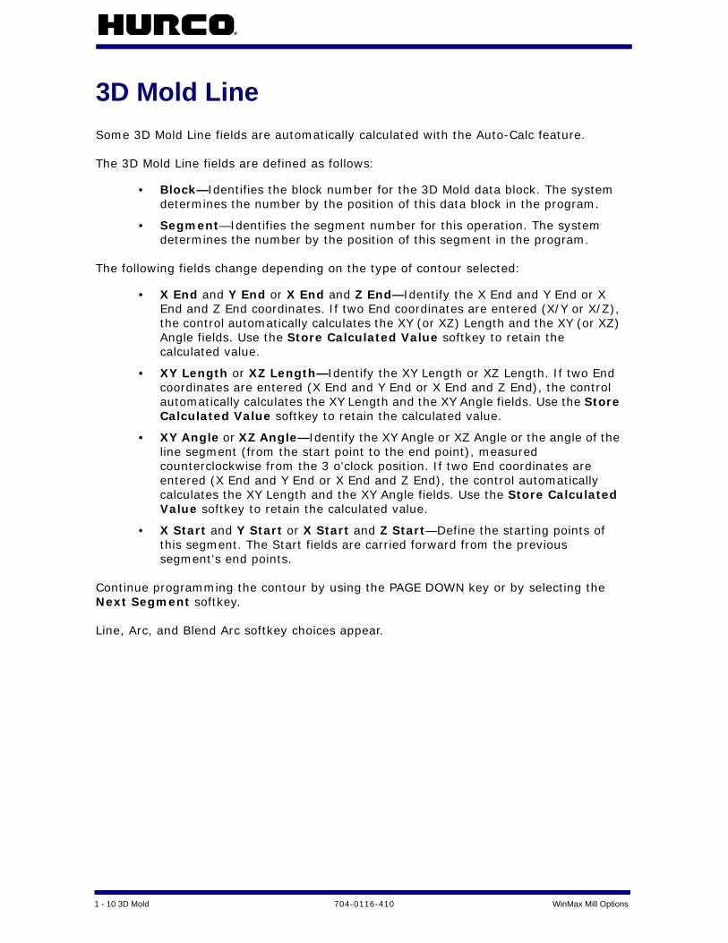
3D Mold LineSome 3D Mold Line fields are automatically calculated with the Auto-Calc feature.
The 3D Mold Line fields are defined as follows:
• Block—Identifies the block number for the 3D Mold data block. The system determines the number by the position of this data block in the program.
• Segment—Identifies the segment number for this operation. The system determines the number by the position of this segment in the program.
The following fields change depending on the type of contour selected:
• X End and Y End or X End and Z End—Identify the X End and Y End or X End and Z End coordinates. If two End coordinates are entered (X/Y or X/Z), the control automatically calculates the XY (or XZ) Length and the XY (or XZ) Angle fields. Use the Store Calculated Value softkey to retain the calculated value.
• XY Length or XZ Length—Identify the XY Length or XZ Length. If two End coordinates are entered (X End and Y End or X End and Z End), the control automatically calculates the XY Length and the XY Angle fields. Use the Store Calculated Value softkey to retain the calculated value.
• XY Angle or XZ Angle—Identify the XY Angle or XZ Angle or the angle of the line segment (from the start point to the end point), measured counterclockwise from the 3 o'clock position. If two End coordinates are entered (X End and Y End or X End and Z End), the control automatically calculates the XY Length and the XY Angle fields. Use the Store Calculated Value softkey to retain the calculated value.
• X Start and Y Start or X Start and Z Start—Define the starting points of this segment. The Start fields are carried forward from the previous segment's end points.
Continue programming the contour by using the PAGE DOWN key or by selecting the Next Segment softkey.
Line, Arc, and Blend Arc softkey choices appear.

WinMax Mill Options 704-0116-410 3D Mold 1-11
3D Mold ArcSome 3D Mold Arc fields are automatically calculated with the Auto-Calc feature.
The 3D Mold Arc fields are defined as follows:
• Block—Identifies the block number for the 3D Mold data block. The system determines the number by the position of this data block in the program.
• Segment—Identifies the segment number for this operation. The system determines the number by the position of this segment in the program.
• Direction—Determines the direction of the arc from the start point (clockwise or counterclockwise).
The following fields change depending on the type of contour selected:
• X End and Y End or X End and Z End—Identify data coordinates (values for X End and Y End or X End and Z End) used in the automatic calculations. Use the Store Calculated Value softkey to retain the calculated value.
• X Center and Y Center or X Center and Z Center—Identify data coordinates (values for X Center and Y Center or X Center and Z Center) used in the automatic calculations. Use the Store Calculated Value softkey to retain the calculated value.
• Radius—Identifies the value for the Radius. The radius is used in the automatic calculations. Use the Store Calculated Value softkey to retain the calculated value.
• Sweep Angle—identifies the angular distance in degrees from the start point of the arc to the end point. The range is -360° to 360°. This field is available when the Arc Sweep Angle option is installed.
• X Start and Y Start or X Start and Z Start—Define the starting points of this segment. The Start fields are carried forward from the previous segment's end points.
Continue programming the contour by using the PAGE DOWN key or by selecting the Next Segment softkey.
Line, Arc, and Blend Arc softkey choices appear.

1 - 12 3D Mold 704-0116-410 WinMax Mill Options
3D Mold Blend ArcA blend arc is an arc that joins two other segments and is tangent to both. Use a blend arc to join two line segments, to join a line segment and an arc segment, or to join two arc segments. The segments to be joined must have a theoretical point of intersection.
If the only information known about an arc is its radius, it is easier to program it as a blend arc if the segments intersect.
The 3D Mold Blend Arc fields are defined as follows:
• Block—Identifies the block number for this operation. The system determines the number by the position of this data block in the program.
• Segment—Identifies the segment number for this operation. The system determines the number by the position of this segment in the contour.
• Radius—Identifies the radius of the arc.
• Direction—Identifies the direction of the arc from the start point (clockwise or counterclockwise).
The following fields change depending on the type of contour selected:
• X Start and Y Start or X Start and Z Start—Define the starting points of this segment. The Start fields are carried forward from the previous segment's end points.
• X End and Y End or X End and Z End—Identify the End coordinates.
• X Center and Y Center or X Center and Z Center—Identify the X Center and Y Center or X Center and Z Center coordinates used to define the circular path of the blend arc.
Continue programming the contour by using the PAGE DOWN key or by selecting the Next Segment softkey.
Line, Arc, and Blend Arc softkey choices appear.

WinMax Mill Options 704-0116-410 3D Mold 1-13
Roughing and Finishing ToolsIn many applications, a Flat End Mill can be used for roughing, followed by a Ball-Nosed End Mill, which is required for cutting the finished surface.
Figure 1–10. Flat End Mill on a Contour
1 First Data Block Using a Flat End Mill
2 Programmed Contour
3 Material to be Removed by Ball-Nosed End Mill

1 - 14 3D Mold 704-0116-410 WinMax Mill Options
Figure 1–11. Ball-Nosed End Mill on a Contour
1 Second Data Block Using a Ball-Nosed End Mill
2 Programmed Contour (Same Contour as Data Block 1)
3 Material to be Removed by Ball-Nosed End Mill

WinMax Mill Options 704-0116-410 3D Mold 1-15
• Flat End Mill - the cutter path is computed as if a Ball-Nosed End Mill is used. This computation allows a Flat End Mill to be used for roughing without gouging the part, and in most cases leaves enough material to be removed for the finished surface using a Ball-Nosed End Mill.
Figure 1–12. Flat End Mill
1 Tool Calibrated on Tip
2 Tool Calculated as center of imaginary ball nose
3 Tool Zero

1 - 16 3D Mold 704-0116-410 WinMax Mill Options
• Ball-Nosed End Mill - the system computes the compensated cutter path of the ball center:
Figure 1–13. Ball-Nosed End Mill
Special consideration must be taken when using a Finish Tool for a Mill Frame, Mill Circle or Mill Contour.
1 Tool Calibrated on Tip
2 Tool Calculated as center of ball nose
3 Tool Zero

WinMax Mill Options 704-0116-410 3D Mold 1-17
Roughing and Finishing PassesThe Flat End Mill tool path is calculated as a Ball-Nosed End Mill for the roughing pass.
The maximum additional material remaining on the overall 3D contour will not exceed the tool's radius.
Figure 1–14. Roughing and Finishing Passes
1 Roughing Contour Using Flat End Mill
2 Finishing Contour Using Ball-Nosed End Mill
3 Extra Material

1 - 18 3D Mold 704-0116-410 WinMax Mill Options

WinMax Mill Options 704-0116-410 Custom Drill 2-1
CUSTOM DRILL
The Custom Drill feature can be used to adjust the feedrate and speed for each step in the drill cycle: entry into hole, break out through bottom of material, bottom, re-entry into hole from bottom, out move at top of hole, and the move to retract clearance plane. Custom Drill is typically used for long hole drill cycles but can be used to customize any drill cycle.
Tool Tab . . . . . . . . . . . . . . . . . . . . . . . . . . . . . . . . . . . . . . . . . . . . . . . . . 2 - 1
Entry Tab . . . . . . . . . . . . . . . . . . . . . . . . . . . . . . . . . . . . . . . . . . . . . . . . 2 - 3
Break Out Tab . . . . . . . . . . . . . . . . . . . . . . . . . . . . . . . . . . . . . . . . . . . . . 2 - 4
Bottom Tab . . . . . . . . . . . . . . . . . . . . . . . . . . . . . . . . . . . . . . . . . . . . . . . 2 - 5
Re-entry Tab . . . . . . . . . . . . . . . . . . . . . . . . . . . . . . . . . . . . . . . . . . . . . . 2 - 6
Out Tab. . . . . . . . . . . . . . . . . . . . . . . . . . . . . . . . . . . . . . . . . . . . . . . . . . 2 - 7
Retract Tab . . . . . . . . . . . . . . . . . . . . . . . . . . . . . . . . . . . . . . . . . . . . . . . 2 - 8
Tool TabThe Custom Drill screen is organized into tabs where the feed, speed, and other parameters are entered for each step of the drill cycle. The first tab is the Tool tab:
Figure 2–1. Custom Drill Tool tab
A list of all hole operations are displayed on the Tool tab to show the relation of the Custom Drill cycle with other operations in the block. Fields are:
• Tool—specifies the tool to be used for the operation.

2 - 2 Custom Drill 704-0116-410 WinMax Mill Options
• Peck Type—specifies whether the drill pulls out to the Z Start position after reaching Peck Depth (Standard) or if it dwells at the Peck Depth (Chip Breaker). Default is Standard.
• Peck Depth—specifies the distance the tool drills down into the part before stopping to clear out or break the chips. If this field is used, it is usually not larger than the tool's diameter. If Peck Depth is zero, Peck Type is ignored.

WinMax Mill Options 704-0116-410 Custom Drill 2-3
Entry TabThe Entry step establishes the speed and feed for the approach move starting at Z Start and ending at Z Top. The image shows the move from Z Start to Z Top:
Figure 2–2. Custom Drill Entry tab
Fields are:
• Z Start—specifies the feed starting point. The move to Z Start is at rapid feedrate from the retract clearance plane.
• Z Top—specifies the position of the entry move into the material at the specified speed and feed.
• Speed—specifies the spindle speed for the move from Z Start to Z Top.
• Feed—specifies the plunge feedrate for the move from Z Start to Z Top.
2 - 4 Custom Drill 704-0116-410 WinMax Mill Options
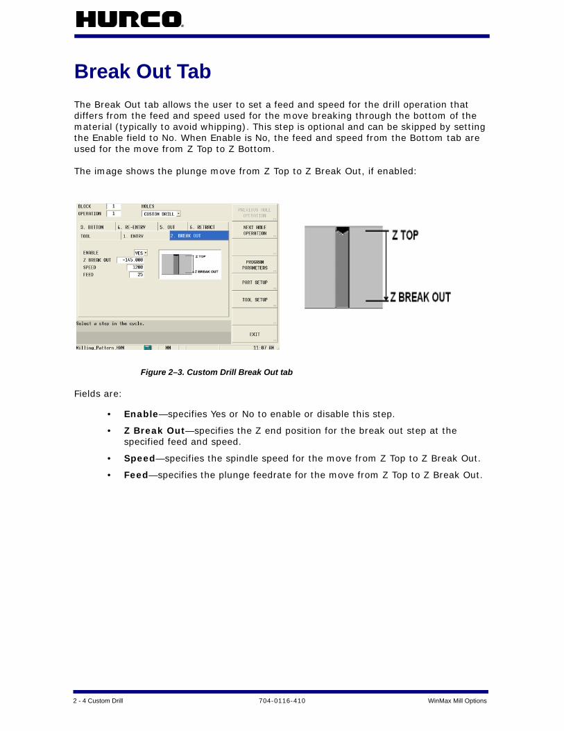
Break Out TabThe Break Out tab allows the user to set a feed and speed for the drill operation that differs from the feed and speed used for the move breaking through the bottom of the material (typically to avoid whipping). This step is optional and can be skipped by setting the Enable field to No. When Enable is No, the feed and speed from the Bottom tab are used for the move from Z Top to Z Bottom.
The image shows the plunge move from Z Top to Z Break Out, if enabled:
Figure 2–3. Custom Drill Break Out tab
Fields are:
• Enable—specifies Yes or No to enable or disable this step.
• Z Break Out—specifies the Z end position for the break out step at the specified feed and speed.
• Speed—specifies the spindle speed for the move from Z Top to Z Break Out.
• Feed—specifies the plunge feedrate for the move from Z Top to Z Break Out.

WinMax Mill Options 704-0116-410 Custom Drill 2-5
Bottom TabThe final move through the hole from Z Break Out to Z Bottom is set in the Bottom tab. If the previous Break Out step is not enabled, then the feed and speed set in this step are used for the entire move from Z Top to Z Bottom.
The image shows the motion for the plunge move from Z Break Out to Z Bottom:
Figure 2–4. Custom Drill Bottom tab
Fields are:
• Z Bottom—specifies the Z bottom of the finished hole.
• Speed—specifies the spindle speed for the move from Z Break Out to Z Bottom.
• Feed—specifies the plunge feedrate for the move from Z Break Out to Z Bottom.

2 - 6 Custom Drill 704-0116-410 WinMax Mill Options
Re-entry TabThe Re-entry step allows the user to set a speed and feed for the retract move from Z Bottom to a Z position back inside the hole (Z Re-entry). This step is optional and can be skipped by setting the Enable field to No. When Enable is No, the move occurs from Z Bottom to the next enabled step (Out or Retract). If there are no other enabled steps, the spindle moves at rapid out of the hole to the Z start location.
The image shows the move from Z Bottom to Z Re-entry, if enabled:
Figure 2–5. Custom Drill Re-entry tab
Fields are:
• Enable—specifies Yes or No to enable or disable this step.
• Z Re-entry—specifies the Z end position of the re-entry move back into the hole at the specified speed and feed.
• Speed—specifies spindle speed for the move from Z Bottom to Z Re-entry.
• Feed—specifies the retract feedrate for the move from Z Bottom to Z Re-entry.

WinMax Mill Options 704-0116-410 Custom Drill 2-7
Out TabThe Out step allows the user to set the speed and feedrate for the retract move from Z Re-entry to Z Out. This step is optional and can be skipped by setting the Enable field to No. When Enable is No, the move occurs from the last enabled step (Bottom or Re-entry) to the Retract step, if it is enabled. If the Retract step is not enabled, the spindle moves at rapid from the last enable step (Bottom or Re-entry) out of the hole to the Z start location.
The image shows the move from Z Re-entry to Z Out, if enabled:
Figure 2–6. Custom Drill Out tab
Fields are:
• Enable—specifies Yes or No to enable or disable this step.
• Z Out—specifies the Z end position of the retract move from Z Re-entry.
• Speed—specifies the spindle speed for the move from Z Re-entry to Z Out.
• Feed—specifies the retract feedrate for the move from Z Re-entry to Z Out.

2 - 8 Custom Drill 704-0116-410 WinMax Mill Options
Retract TabThe Retract step allows the user to set the feed and speed for the move from Z Out to Z Retract. This step is optional and can be skipped by setting the Enable field to No. When Enable is No, the tool moves at rapid feedrate from the last enabled step (Bottom, Re-entry, or Out) to the Z Start position.
From Z Retract, the tool moves at rapid feedrate to the retract clearance plane; therefore, Z Retract should be less than the retract clearance plane.
The image shows the retract move from Z Out to Z Retract:
Figure 2–7. Custom Drill Retract tab
Fields are:
• Enable—specifies Yes or No to enable or disable this step.
• Z Retract—specifies the Z position of the retract move at the specified speed and feed. Z Retract can be greater than, less than, or equal to Z Start.
• Speed—specifies the spindle speed for the move from Z Out to Z Retract.
• Feed—specifies the retract feedrate for the move from Z Out to Z Retract.

WinMax Mill Options 704-0116-410 DXF Option 3-1
DXF OPTION
These topics are discussed in this section:
DXF Overview . . . . . . . . . . . . . . . . . . . . . . . . . . . . . . . . . . . . . . . . . . . . . 3 - 2
DXF Build Data Block . . . . . . . . . . . . . . . . . . . . . . . . . . . . . . . . . . . . . . . . 3 - 3
DXF Parameters . . . . . . . . . . . . . . . . . . . . . . . . . . . . . . . . . . . . . . . . . . . . 3 - 4
Edit Drawing . . . . . . . . . . . . . . . . . . . . . . . . . . . . . . . . . . . . . . . . . . . . . . 3 - 5
DXF Layers . . . . . . . . . . . . . . . . . . . . . . . . . . . . . . . . . . . . . . . . . . . . . . . 3 - 9
3 - 2 DXF Option 704-0116-410 WinMax Mill Options
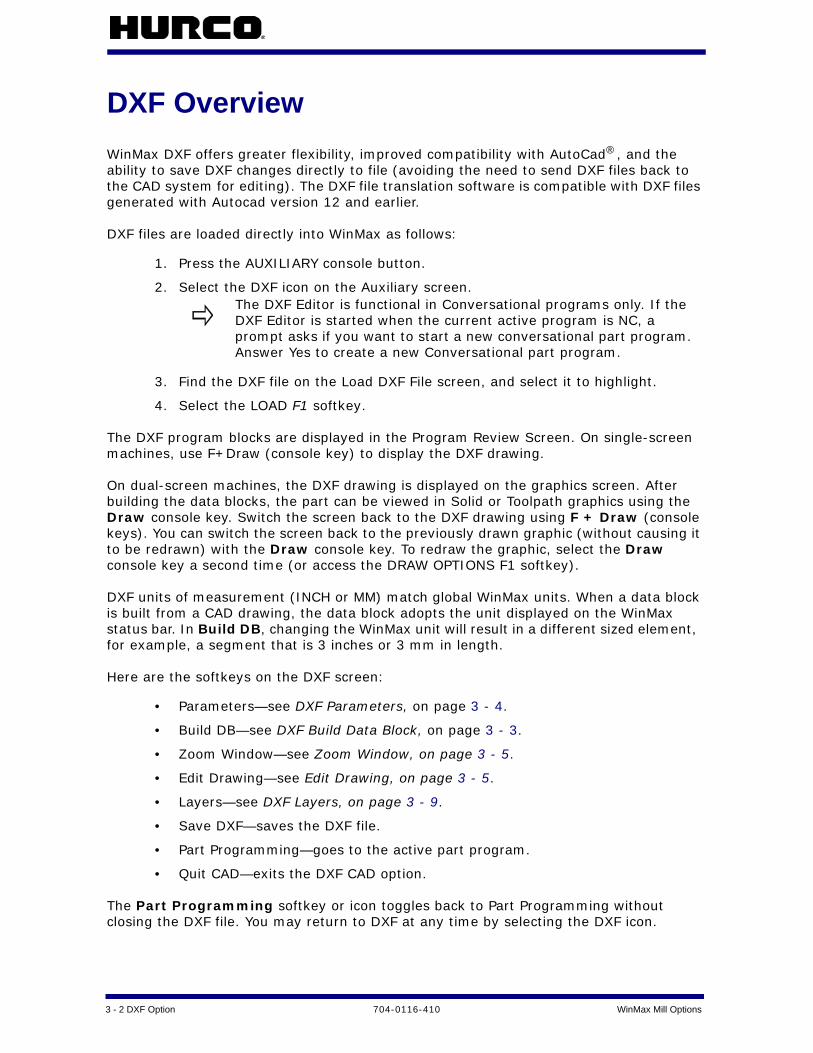
DXF OverviewWinMax DXF offers greater flexibility, improved compatibility with AutoCad®, and the ability to save DXF changes directly to file (avoiding the need to send DXF files back to the CAD system for editing). The DXF file translation software is compatible with DXF files generated with Autocad version 12 and earlier.
DXF files are loaded directly into WinMax as follows:
1. Press the AUXILIARY console button.
2. Select the DXF icon on the Auxiliary screen.
3. Find the DXF file on the Load DXF File screen, and select it to highlight.
4. Select the LOAD F1 softkey.
The DXF program blocks are displayed in the Program Review Screen. On single-screen machines, use F+Draw (console key) to display the DXF drawing.
On dual-screen machines, the DXF drawing is displayed on the graphics screen. After building the data blocks, the part can be viewed in Solid or Toolpath graphics using the Draw console key. Switch the screen back to the DXF drawing using F + Draw (console keys). You can switch the screen back to the previously drawn graphic (without causing it to be redrawn) with the Draw console key. To redraw the graphic, select the Draw console key a second time (or access the DRAW OPTIONS F1 softkey).
DXF units of measurement (INCH or MM) match global WinMax units. When a data block is built from a CAD drawing, the data block adopts the unit displayed on the WinMax status bar. In Build DB, changing the WinMax unit will result in a different sized element, for example, a segment that is 3 inches or 3 mm in length.
Here are the softkeys on the DXF screen:
• Parameters—see DXF Parameters, on page 3 - 4.
• Build DB—see DXF Build Data Block, on page 3 - 3.
• Zoom Window—see Zoom Window, on page 3 - 5.
• Edit Drawing—see Edit Drawing, on page 3 - 5.
• Layers—see DXF Layers, on page 3 - 9.
• Save DXF—saves the DXF file.
• Part Programming—goes to the active part program.
• Quit CAD—exits the DXF CAD option.
The Part Programming softkey or icon toggles back to Part Programming without closing the DXF file. You may return to DXF at any time by selecting the DXF icon.
The DXF Editor is functional in Conversational programs only. If the DXF Editor is started when the current active program is NC, a prompt asks if you want to start a new conversational part program. Answer Yes to create a new Conversational part program.

WinMax Mill Options 704-0116-410 DXF Option 3-3
DXF Build Data BlockThe Build DB softkey accesses the automatic data block building features. The system creates milling, holes, position, or pattern locations data blocks.
Milling - the Milling operation softkeys perform these functions in Lines/Arcs, Circles, Frame, 3D Mold, or Ellipse data blocks:
• Accept—loads the entity into the data block.
• Zoom Window—refer to Zoom Window, on page 3 - 5.
• Edit Drawing—refer to Edit Drawing, on page 3 - 5.
• Reverse—reverses the contour direction.
• AutoChain—defines contours by autochaining individual segments together.
• Default Radius—inserts the value of the default radius set in the Frame screen’s Corner Radius field.
• Exit/Cancel—cancels the operation and returns to the previous screen.
If you are using AutoCAD 14, set the registers to generate Polylines and Ellipses so they are saved as pline entity types and not splines.
Holes - Holes data blocks are built using the Hole Location Method (F1) or the Hole Pattern Method (F2):
• Use Hole Location Method—builds Holes Locations blocks from selected points on the drawing.
• Use Hole Pattern Method—builds Holes Pattern blocks from selected points on the drawing.
For either softkey, select holes on the drawing with one of three methods:
• Select individual holes on the touchscreen.
• Choose the Window Select softkey and drag across an area of the screen to select a group of holes.
• Use the Intersect softkey to select two intersecting lines. The point of intersection becomes the center of the hole.
Select the Accept softkey to create the data blocks.
These are the softkeys in the Holes menu:
• Accept—loads the entity into the data block.
• Zoom Window— refer to Zoom Window, on page 3 - 5.
• Edit Drawing—refer to Edit Drawing, on page 3 - 5.
• Window Select—selects a group of holes on the drawing.
• Intersect—draws a hole at the intersection of two selected lines and represents the center with a highlighted plus (+).
• Default Order—orders the holes as they were selected in the AutoCAD drawing.

3 - 4 DXF Option 704-0116-410 WinMax Mill Options
• Exit/Cancel—cancels the operation and returns to the previous screen.
Position - creates a Position data block from the DXF drawing. These are the softkeys on the Position menu:
• Accept—loads the entity into the data block.
• Zoom Window—refer to Zoom Window, on page 3 - 5.
• Edit Drawing—refer to Edit Drawing, on page 3 - 5.
• Window Select—selects a group of holes on the drawing.
• Intersect—draws a hole at the intersection of two selected lines and represents the center with a highlighted plus (+).
• Default Order—orders the holes as they were drawn in the original AutoCAD drawing.
• Exit/Cancel—cancels the operation and returns to the previous screen.
Pattern Locations—builds a Pattern data block. To use, select the softkey and then select points on the drawing to serve as pattern locations, using one of the following methods:
• Select individual holes on the touchscreen.
• Choose the Window Select softkey and drag across an area of the screen to select a group of holes.
• Use the Intersect softkey to select two intersecting lines. The point of intersection becomes the center of the hole.
Select the Accept softkey to create an empty Pattern Locations data block. Additional data can then be added either manually or from the DXF drawing.
These are the softkeys on the Pattern Locations menu:
• Accept—loads the entity into the data block.
• Zoom Window— refer to Zoom Window, on page 3 - 5.
• Edit Drawing—refer to Edit Drawing, on page 3 - 5.
• Window Select—selects a group of holes on the drawing.
• Intersect—specifies a pattern location at the intersection of two selected lines.
• Default Order—orders the holes as they were selected in the AutoCAD drawing.
• Exit/Cancel—cancels the operation and returns to the previous screen.
DXF ParametersThese parameters link contour segments, define part zero within the drawing, and set the radius for frame corners.
Use the Move Zero and Select Value softkeys to change the location of part zero. The Exit

WinMax Mill Options 704-0116-410 DXF Option 3-5
softkey returns to the DXF softkeys.
The fields on the DXF Parameters dialog box are defined as follows:
• Endpoint Tolerance—determines when the endpoints of segments are close enough to be considered equal (or coincident).
• Part X Offset and Part Y Offset—define part zero within the drawing. All dimensions are calculated from this point. The part zero symbol is a circle with crosshairs. To change this location manually, move the cursor to the field for Part X or Y Offset and enter the X or Y Offset values. To change this location graphically and automatically, use the Move Zero softkey.
• Frame Radius—sets a default corner radius to be used in Build DB. If the corners of a frame do not have the same radius, the user is prompted to either select a corner radius on the drawing or use the default value entered in this field for the radius.
• Hole Diameter—determines the default diameter for a hole.
Use the touchscreen to turn the remaining DXF Parameter fields on ( ) or off ( ):
• Display Geometry—shows selected lines on the graphic display in a color other than black, illustrating which elements have been selected. Colors can be changed with the Choose Colors softkey on the Parameters screen.
• Autochain Contours—allows autochaining to be turned off so that a contour may be created by individually selected segments into a chained contour. By default, segments are automatically chained to create contours.
• Select Holes by Diameter—selects holes with the diameter specified in the Hole Diameter field (defined above) when the WINDOW SELECT softkey is used. This selection allows you to order the hole selection by size, which optimizes tool changes.
Zoom Window
Use the Zoom Window softkey to enlarge an area of the drawing or zoom out to see a full view. Use the pointer to touch an area on the screen and drag across the screen to enlarge an area of the drawing. When an area is enlarged, use the following softkeys:
• Zoom Out—pulls back from the drawing incrementally to the previous magnification level without re-centering the part in the drawing.
• Fit to View—gives a full scale of the drawing with the part in the drawing auto-centered.
• Pan—relocates the center of the drawing on the Graphic display.
• Exit—returns to the previous menu.
Edit DrawingUse the Edit drawing feature to extend, join, modify, or split segments that need to be edited in order to create the proper geometry for the part program.

3 - 6 DXF Option 704-0116-410 WinMax Mill Options
• Extend—locates the intersection of two lines and extends one or both of the lines to the intersection point.
To extend lines, select the EDIT DRAWING softkey and then the Extend softkey. Select the two lines that need to be extended. Both lines are highlighted when selected and extended to their points of intersection as shown in the examples below:
Figure 3–1. Extended Lines and Arcs
A Original drawing
B Edited drawing
1 Extended line
2 Both lines extended
3 Start of arc
4 Selected intersection point
5 Extended arc

WinMax Mill Options 704-0116-410 DXF Option 3-7
• Join—moves a selected line endpoint to the endpoint of a line or arc segment. Always select as the first endpoint the point that will be joined to the second endpoint. The endpoint at the opposite end of the first selected segment remains stationary and becomes a pivoting point. Both segments are highlighted when selected, and the screen is redrawn to reflect the joining of the two segments.
• Modify—is used to view or modify the actual geometry data of segments. Choose the SELECT POINT softkey to view the segment data.
• The DXF Edit Modify - Arc dialog box appears if you select an arc. Refer to DXF Edit Modify - Arc, on page 3 - 8.
• The DXF Edit Modify - Line dialog box appears if you select a line. Refer to DXF Edit Modify - Line, on page 3 - 8.
• The DXF Edit Modify - Point dialog box appears if you select a point. Refer to DXF Edit Modify - Point, on page 3 - 8.
• The segment appears gray on the Graphic display.
Choose the Accept softkey to retain the changes in the control's memory.
Figure 3–2. Joined Lines and Arcs
A Original drawing
B Edited drawing
1 Stationary endpoint
2 Selected segment endpoint
3 Joining endpoint
4 Newly joined segment
3 - 8 DXF Option 704-0116-410 WinMax Mill Options
• Split—use to divide segments for selection, de-selection, and chaining. Segments may be split at midpoint or any point of intersection with other segments.
To split a segment, first select the segment and then select the point where the segment will be divided. When a segment is selected for splitting, the midpoint and all intersection points with the other segments are indicated with crosshair markers. Follow the directions in the Prompt display.
• Delete—deletes a programmed endpoint.
• Trim—trims a selected segment.
• Explode PCurve—shows an exploded view of a selected PolyCurve. If you are using AutoCAD 14, set the registers to generate Polylines and Ellipses so they are saved as pline entity types and not splines.
• Exit/Cancel—return to the Main DXF menu.
DXF Edit Modify - Arc
The DXF Edit Modify - Arc dialog window contains these fields:
• Start Angle—defines the starting point of the angle.
• Sweep Angle—defines the total number of degrees in the arc to be cut. This number can be greater than 350.
• Direction—identifies the direction of the arc from the start point.
• Radius—identifies the radius of the arc.
• Center X and Center Y—identify the X and Y coordinates for the center point of the arc.
DXF Edit Modify - Line
The DXF Edit Modify - Line dialog window contains these fields:
• Endpoint1 X and Endpoint1 Y—define the first endpoints for the X and Y coordinates.
• Endpoint2 X and Endpoint2 Y—define the second endpoints for the X and Y coordinates.
• Length—identifies the line length.
• XY Angle—identifies the angle of the XY coordinate.
DXF Edit Modify - Point
The DXF Edit Modify - Point dialog window contains these fields:
• X Value—identifies the X location for the selected point.
• Y Value—identifies the Y location for the selected point.

WinMax Mill Options 704-0116-410 DXF Option 3-9
DXF LayersMany DXF drawings use layers - an electronic method of representing transparent acetate overlays used in hand-drawn drafting work.
• Select Layer—toggles the highlighted layer on and off.
• All On—turns on all of the layers.
• All Off—turns off all of the layers.
• Exit—return to the Main DXF menu.

3 - 10 DXF Option 704-0116-410 WinMax Mill Options

WinMax Mill Options 704-0116-410 HD3 Serial Number Lettering 4-1
HD3 SERIAL NUMBER LETTERING
HD3 Serial Number Lettering mills a sequence of unique serial numbers that increment each time the block is run. The characters are HD3-style (non-true type) and can be alphabetic A-Z, numeric 0-9, and special characters @#!$^&*()-[]_=+’:;%?/<>,.\. Alpha characters are all upper case. The last character in the serial number must be numeric and is incremented by a specified amount.
• Users can manually provide serial number data, which includes a starting sequence, such as 0001 or ABC001, and an increment which advances the serial number for each subsequent run.
• Data can originate from a file in which the serial numbers are listed. Each time the block is run, the next serial number is extracted from the file. The format of this file must be one serial number per line, each line must end in a carriage return, line feed sequence, or Return key.
To create an HD3 Serial Number Lettering block from the New Block Screen:
1. Select the Milling softkey.
2. Select the More softkey twice.
3. Select the HD3 Serial Number Lettering softkey on New Block screen 3.
The HD3 Serial Number Lettering screen uses three tabs: Text, Orientation, and Format.
Text tab . . . . . . . . . . . . . . . . . . . . . . . . . . . . . . . . . . . . . . . . . . . . . . . . . 4 - 1
Orientation tab. . . . . . . . . . . . . . . . . . . . . . . . . . . . . . . . . . . . . . . . . . . . . 4 - 3
Format tab. . . . . . . . . . . . . . . . . . . . . . . . . . . . . . . . . . . . . . . . . . . . . . . . 4 - 4
Text tabThe text of the serial number is set up in the Text tab:

4 - 2 HD3 Serial Number Lettering 704-0116-410 WinMax Mill Options
Figure 4–1. HD3 Serial Number Lettering Text tab
Fields are:
• X Reference—indicates the X coordinate of the point where text begins.
• Y Reference—indicates the Y coordinate of the point where text begins.
• Character Height—indicates the height of the text.
• Character Width—indicates the character width. The width includes the character left-justified, plus some spacing between it and the next character to be milled. Spacing between the characters is equal to the tool's diameter.
• Z Start—indicates the point where the Z-axis plunge feedrate begins.
• Z Bottom—indicates the location where the Z-axis plunge feedrate ends and mill feed begins.
• Data Origin—specifies the source of the serial number data, either User-provided or From File. Default is User-Provided.
• User-provided—the serial numbers are constructed with information provided by the user. When selected, the Starting Sequence and Increment fields appear.
• From File—the serial numbers are populated from a source file. When selected, the File field and Locate... button appear.
• Starting Sequence—specifies the characters for the first serial number. The sequence can contain any combination of alpha or numeric characters, but the last character in the sequence must be a digit (number). This field appears only when User-provided Data Origin is selected. Default is 1.
• Increment—specifies the amount to increment for each new serial number. This field appears only when User-provided Data Origin is selected. Default is 1.
Because cutter compensation is not used in this routine and letter contouring follows the center of the tool, character spacing can be adjusted by adjusting the tool diameter in Tool Setup.

WinMax Mill Options 704-0116-410 HD3 Serial Number Lettering 4-3
• File—specifies the source file for serial numbers that are generated from a file. This field appears only when From File Data Origin is selected.
The file must be located on the hard drive or an accessible network drive, or can be on a floppy disk or USB memory device that has been loaded onto the control. To select the file:
1. Select the Locate... button to browse for the file.
2. Navigate to the location of the file in the dialog box that opens.
3. Select the file.
4. Select the Open button on the dialog box. The file and path appear in the File field.
Orientation tabThe Orientation fields specify the orientation of the X and Y reference points.
Fields are:
• X Ref Location—specifies Start, End, or Center of the character for the X reference point. Default is Start.
• Start—the serial number is left-justified; the first character begins at the X reference point.
• Center—the entire serial number is centered left and right of the X reference point.
• End—the serial number is right-justified; the last character ends at the X reference point.
• Y Ref Location—specifies Bottom, Top, or Center of the character for the Y reference point. Default is Bottom.
• Bottom—the bottom of the serial number is aligned with the Y reference point.
• Top—the top of the serial number is aligned with the Y reference point.
• Center—the serial number is centered above and below the Y reference point.

4 - 4 HD3 Serial Number Lettering 704-0116-410 WinMax Mill Options
Figure 4–2. X Reference and Y Reference locations
Format tabThe Format fields indicate whether the serial number should have a minimum length and what that length should be.
Fields are:
• Assure Minimum Length—specifies Yes or No. When Yes is selected, the Minimum Length and Leading Symbol fields appear so that a placeholder can be used to achieve consistent serial number length. Default is Yes.
• Minimum Length—specifies the length (in number of characters) when Assure Minimum Length field is set to Yes. This field only appears when Assure Minimum Length is Yes.
• Leading Symbol—specifies the character that is added to the beginning of the serial number as a placeholder to achieve the minimum length. This can be an alpha or a numeric character. This character will be repeated in the serial number as many times as necessary to achieve the specified minimum length with the given starting sequence. See example below. This field only appears when Assure Minimum Length is Yes.
Start Center End
X Reference
Y Reference
Bottom
Top
Center

WinMax Mill Options 704-0116-410 HD3 Serial Number Lettering 4-5
Leading Symbol Example:Starting Sequence 001
Increment 1
Assure Minimum Length Yes
Minimum Length 5
Leading Symbol A
First Serial Number will be AA001 NOTE: A second “A” is added to starting sequence of 001 to assure the minimum length of 5.
Second Serial Number will be AA002
999th Serial Number will be AA999
1000th Serial Number will be A1000 NOTE: The second “A” is no longer needed to assure minimum length.
If serial number “AA1000” is required, the Starting Sequence would be AA001 and Assure Minimum Length would be set to No.
Format tab only assures a minimum number of characters. The serial number will continue to increment and expand with continuous running of the block.

4 - 6 HD3 Serial Number Lettering 704-0116-410 WinMax Mill Options

WinMax Mill Options 704-0116-410 Helical Plunge Option 5-1
HELICAL PLUNGE OPTION
The Helical Plunge programming option provides helical plunge as an alternative machining strategy. Helical plunge and straight plunges can be used separately for roughing and finishing phases, or they can be used together for the same operation. For example, you can rough with a helical plunge and finish with a straight plunge.
In the Helical Plunge option, the tool rotates around the cut and moves down the Z-axis. The cutting tool is continuously cutting deeper and enters and exists the machined part only once.
To use Helical Plunge, set the Mill or Finish Plunge Type in Milling Parameters to Helix.
Helical Plunge Milling Parameter Fields . . . . . . . . . . . . . . . . . . . . . . . . . . . . 5 - 2
Helical Plunge (Inside/Outside) for Mill Frames, Mill Circles and Ellipses . . . . . 5 - 3
Helical Plunge with UltiPocket. . . . . . . . . . . . . . . . . . . . . . . . . . . . . . . . . . . 5 - 3
Helical Plunge with Operator Specified Location . . . . . . . . . . . . . . . . . . . . . . 5 - 3
Helical Plunge in the Center of a Pocket. . . . . . . . . . . . . . . . . . . . . . . . . . . . 5 - 3
Helical Plunge with Outward Pocketing . . . . . . . . . . . . . . . . . . . . . . . . . . . . 5 - 4
Helical Plunge of Mill Frame Inside with No Pecking and Blend Offset . . . . . . . 5 - 4
Helical Plunging of Mill Frame Inside with Pecking and Straight Plunge Finish Pass and Blend Offset. . . . . . . . . . . . . . . . . . . . . . . . . . . . . . . . . . . . . . . . . . . . . . . 5 - 5
Helical Plunge with Lines and Arcs . . . . . . . . . . . . . . . . . . . . . . . . . . . . . . . 5 - 7
Helical Plunge with 3-D Part Programming Option. . . . . . . . . . . . . . . . . . . . . 5 - 7
• Helical Plunge uses the feedrate programmed by the operator on the mill circle, mill frame, ellipse, or mill contour start screens.
• Pattern blocks can be used with helical plunging. A scaled-up or scaled-down pattern will not affect the diameter of the helix plunge. When using a mirror image pattern, the helical plunge will be in the negative Z direction.
• Helical Plunge for rotary mill frames, mill circles, and mill contours is similar to helical plunging for non-rotary mill frames, mill circles, and mill contours.

5 - 2 Helical Plunge Option 704-0116-410 WinMax Mill Options
Helical Plunge Milling Parameter Fields On the Milling Parameters screen, choose the Mill Plunge Type as Helix. If the Helical Plunge option is enabled, the fields specifying the plunging parameters appear. If the fields do not appear, the Helical Plunge option has not been installed on the control. Call Hurco or a Hurco distributor to purchase the option.
• Mill Plunge Type—specifies the plunging strategy to use for the milling pass. Choose Straight or Helix. The default setting is Straight.
• Mill Plunge Ramp Slope—defines the slope of the helical ramp for the milling tool. The range is 1° to 90°. Choosing 90° will result in a Straight Plunge. The default value is 10°.
• Mill Plunge Helix Radius—used for specifying the Helical Plunge radius as a percentage of the tool diameter. The range is from 0% to 100%. Choosing 0% results in a Straight Plunge. If a value of 50% or less is chosen, it will prevent a post (a thin cylinder of material formed after helical plunging) from being formed by the Helical Plunge. The default setting is 25%.
• Finish Plunge Type—specifies the plunging strategy to use for the finish phase. Choose Straight or Helix. The default setting is Straight.
• Finish Plunge Ramp Slope—defines the slope of the Helical Ramp for the finishing tool. Range is 1o to 90o. Choosing 90° will result in a Straight
Plunge. The default setting is 25o.
• Finish Plunge Helix Radius—defines the value of the Helical Plunge radius as a percentage of the diameter of the finishing tool. The range is 0% to 100%. If a value of 50% or less is chosen, it will prevent a post from being formed by the Helical Plunge. The default setting is 25%.
• Operator Specify Pocket Start—if YES, the pocket start location fields will appear on pocket boundary screens, when spiral inward pocketing is selected. The default setting is No. The value of Inward Pocket Plunge Near Center is ignored. Refer to Helical Plunge with UltiPocket, on page 5 - 3 for more information.
• Inward Pocket Plunge Near Center—if YES, UltiPocket will attempt to perform a plunge near the center of the pocket. Using this parameter may help prevent interferences with pocket islands and boundaries. The default setting is No. For this field to be enabled, the Operator Specify Pocket Start value must be No. Refer to Helical Plunge with UltiPocket, on page 5 - 3 for more information.
Helical Plunge Milling Parameter fields are available only in Conversational Programming.

WinMax Mill Options 704-0116-410 Helical Plunge Option 5-3
Helical Plunge (Inside/Outside) for Mill Frames, Mill Circles and Ellipses Helical Plunge is similar for milling the inside or outside of mill frames, circles, and ellipses (with or without blend-in moves). The center location of the helical plunge is the same as a straight plunge. The direction of the helical plunge (clockwise, CW, or counter clockwise, CCW) will be determined by the tool spin direction (CW or CCW) and the milling direction (climb or conventional). If Blend Offset is used, the helical plunge will be centered about the plunge point of the Blend Offset.
The helical plunge direction that provides a smooth transition to the tool path will be chosen. Helical plunge is not allowed when Milling Type On is selected.
Helical Plunge with UltiPocket The Helical Plunge option is used with the UltiPocket option to define the plunging location when inward pocketing. The operator can specify the pocket plunge location using the Operator Specify Pocket Start function, or start the pocket plunge near the center by using the Inward Pocket Plunge Near Center function. See the UltiPocket Option chapter for more information on using the Helical Plunge option with UltiPocket.
When both the Operator Specify Pocket Start and the Inward Pocket Plunge Near Center are set to No, the plunge locations are used that would have been used without the Helical Plunge option.
Helical Plunge with Operator Specified Location When the operator specifies the plunge point, all of the helix plunge moves will occur at that location, even for the pocket boundary.
Helical Plunge in the Center of a Pocket When the Inward Pocket Plunge Near Center field value is Yes (Operator Specify Pocket Start value must be No), a plunge point near the center of the pocket will be chosen. Islands near the center will impact upon the plunge point’s location.
An error message appears if the plunge point specified would violate the programmed part surface.
When machining a part with a lot of webbing (many small pockets separated by walls), it may be desirable to disable helical plunging.

5 - 4 Helical Plunge Option 704-0116-410 WinMax Mill Options
Helical Plunge with Outward Pocketing Helical plunging occurs near the center of the pocket when used with Outward Pocketing, and only one plunge location is needed. The Operator Specify Pocket Start and the Inward Pocket Plunge Near Center fields have no effect on Helical Plunge with Outward Pocketing.
Helical Plunge of Mill Frame Inside with No Pecking and Blend OffsetThe tool will helical plunge to the Z Bottom level and then perform the normal blend-in move. The direction of the helical plunge arc will smoothly transition to the blend-in arc. For instance, if the blend-in arc is CCW, the direction of the helical plunge will be CW. The following isometric views are created by setting the Draw Plunge Moves graphics parameter field to Yes.
The graphics show the finish pass only if a finish tool is specified in the frame block, and do not show individual peck levels.
Figure 5–1. Helical Plunge with No Pecking and Blend Offset (Isometric View)
This graphical representation is only for informational purposes and cannot be viewed with WinMax.

WinMax Mill Options 704-0116-410 Helical Plunge Option 5-5
Helical Plunging of Mill Frame Inside with Pecking and Straight Plunge Finish Pass and Blend OffsetThe following example is a Mill Frame Block Type with Inside Milling Type. The finish tool specified and the peck depth is set to 0.6 inches.
First Peck - The tool helical plunges down to the -first peck depth, then mills another full circle to ensure that all material down to the first peck is removed. After the full circle is completed, a 180o blend in arc is performed. The direction of the helical plunge will always be in the opposite direction of the blend-in arc.
Figure 5–2. First Peck (Isometric View)
Second Peck and All Pecks to Finish Peck Depth - The tool will rapid down to the previous peck depth plus the peck clearance plane. The tool then helical plunges down to the next peck depth or the Z Bottom plus the Finish Z. If the tool is at a peck depth, a 360o arc will be machined. The 360o arc will not be machined if it is the last peck depth. Instead, a blend-in arc will be machined. The blend-in arc for the last peck depth will be similar to the one machined for the first peck.
These graphical representations are only for informational purposes and cannot be viewed with WinMax.

5 - 6 Helical Plunge Option 704-0116-410 WinMax Mill Options
Figure 5–3. Second Peck (Isometric View)
Finish Pass - The tool will rapid down to the Z Start and plunge feed down to the Z Bottom. A blend-in move is performed before milling the frame contour.
Figure 5–4. Finish Pass (Isometric View)
When helical plunge is used for roughing passes, a large amount of material is removed around the point of entry. Therefore, using helical plunging for the finish passes is probably not necessary.
If the finish tool is larger than the roughing tool, helical plunges should also be performed for the finish pass. If a post was created by the roughing tool (the Helix plunge radius was greater than 50 percent) the finish tool may be cutting into the post.

WinMax Mill Options 704-0116-410 Helical Plunge Option 5-7
Helical Plunge with Lines and Arcs Helical plunge with lines and arcs occurs at the start of the contour.
The following example shows helical plunging with right cutter compensation of a contour.
Figure 5–5. Helical Plunging with Lines/Arcs (Isometric View)
Helical Plunge with 3-D Part Programming Option
Helical plunging is supported in the 3-D Part Programming option. A helical plunge can be performed when the Mill Plunge Type field is set to Helix.
Only one helical plunge occurs when using a bi-directional tool path. When performing helical plunge using unidirectional tool path, a helical plunge occurs for each cutter pass.
An error message will be displayed if the helical plunge would cut into a part surface. If this error message appears, move the starting location of the contour to an area that will not cause interference.
When programming complex 3-D parts, the operator should review helical plunge placements in graphical form before milling to ensure helical plunges from one block do not interfere with neighboring blocks.
If Mill Plunge Type field is set to Helix, but the helical plunge does not appear on the graphics screen, check the Z Start field on the Mill 3-D block screen. The plunges may not appear if Z Start value is too low.

5 - 8 Helical Plunge Option 704-0116-410 WinMax Mill Options

Machine WinMax Mill Options 704-0116-410 Rotary 6-1
ROTARY
These topics are discussed in this section:
Rotary Overview. . . . . . . . . . . . . . . . . . . . . . . . . . . . . . . . . . . . . . . . . . . . 6 - 2
Rotary Part Setup . . . . . . . . . . . . . . . . . . . . . . . . . . . . . . . . . . . . . . . . . . . 6 - 8
Rotary Part Programming . . . . . . . . . . . . . . . . . . . . . . . . . . . . . . . . . . . . . 6 - 10
Rotary A and Rotary A Tilt B Configuration . . . . . . . . . . . . . . . . . . . . . . . . . 6 - 14
Tilt A Rotary C Configuration . . . . . . . . . . . . . . . . . . . . . . . . . . . . . . . . . . . 6 - 19
Rotary B Configuration . . . . . . . . . . . . . . . . . . . . . . . . . . . . . . . . . . . . . . . 6 - 24
Tilt B Rotary C Configuration . . . . . . . . . . . . . . . . . . . . . . . . . . . . . . . . . . . 6 - 27
Universal Rotary Configuration . . . . . . . . . . . . . . . . . . . . . . . . . . . . . . . . . . 6 - 32
Calculating X- and Z-Axis Positions After a Tilt-Axis Move . . . . . . . . . . . . . . . 6 - 41
Example Programs . . . . . . . . . . . . . . . . . . . . . . . . . . . . . . . . . . . . . . . . . . 6 - 43
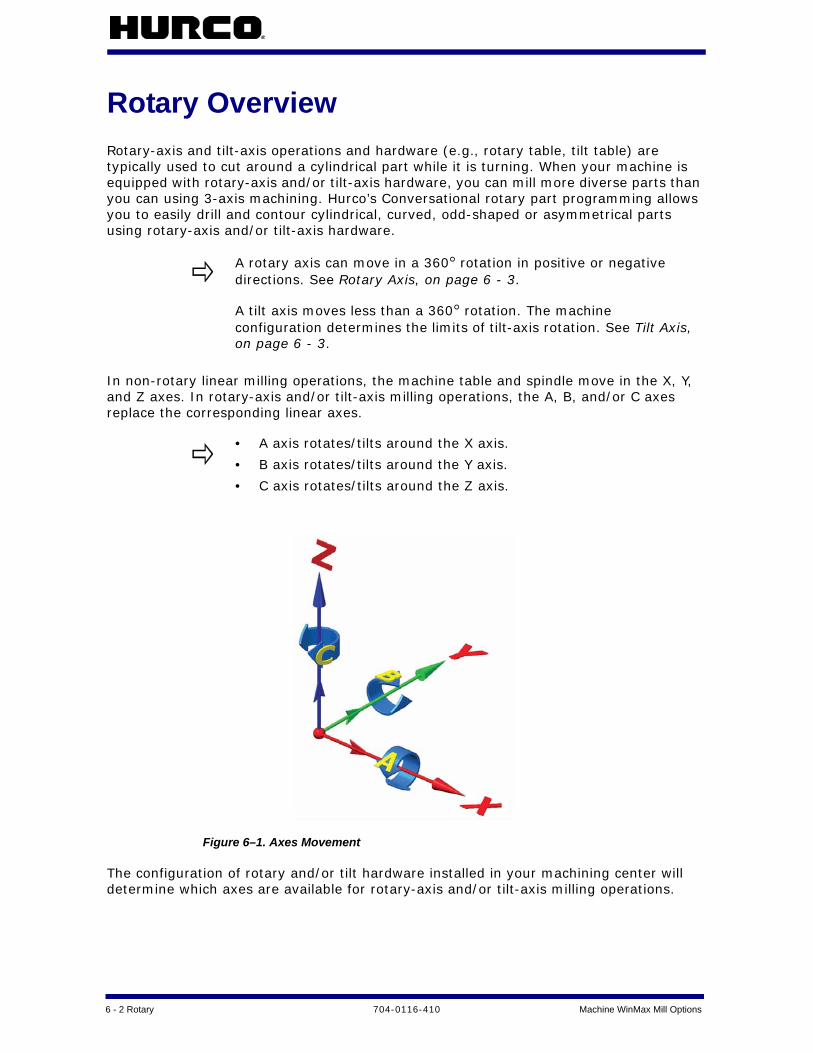
6 - 2 Rotary 704-0116-410 Machine WinMax Mill Options
Rotary OverviewRotary-axis and tilt-axis operations and hardware (e.g., rotary table, tilt table) are typically used to cut around a cylindrical part while it is turning. When your machine is equipped with rotary-axis and/or tilt-axis hardware, you can mill more diverse parts than you can using 3-axis machining. Hurco’s Conversational rotary part programming allows you to easily drill and contour cylindrical, curved, odd-shaped or asymmetrical parts using rotary-axis and/or tilt-axis hardware.
In non-rotary linear milling operations, the machine table and spindle move in the X, Y, and Z axes. In rotary-axis and/or tilt-axis milling operations, the A, B, and/or C axes replace the corresponding linear axes.
Figure 6–1. Axes Movement
The configuration of rotary and/or tilt hardware installed in your machining center will determine which axes are available for rotary-axis and/or tilt-axis milling operations.
A rotary axis can move in a 360° rotation in positive or negative directions. See Rotary Axis, on page 6 - 3.
A tilt axis moves less than a 360° rotation. The machine configuration determines the limits of tilt-axis rotation. See Tilt Axis, on page 6 - 3.
• A axis rotates/tilts around the X axis.
• B axis rotates/tilts around the Y axis.
• C axis rotates/tilts around the Z axis.

Machine WinMax Mill Options 704-0116-410 Rotary 6-3
Rotary Axis
Rotary-axis operations in a Conversational rotary part program are similar to standard milling operations, except that the rotary milling feature (e.g., rotary circle, rotary frame) is wrapped around a cylinder. Rotary-axis operations can be performed on a 4-axis or 5-axis machine where the part is fixtured to the centerline of the rotary-axis.
Tilt Axis
A pivoting rotary table allows you to tilt the table to a specific angle during machining. Any rotary program or standard milling operation can be executed at the tilt position, but the tilt-axis will remain stationary while the data block is being machined. If you want to machine a part while moving the tilt axis, you must use NC programming. Refer to the WinMax Mill NC Programming manual for more information.
See Calculating X- and Z-Axis Positions After a Tilt-Axis Move, on page 6 - 41 for additional information.
Configuration of Hurco Machining Centers
Hurco machining centers provide a variety of machine configurations. Rotary and/or tilt tables can be installed in Hurco machining centers, either at the factory or on-site. Some Hurco machine models come with rotary hardware as standard equipment. The table below shows configurations available for Hurco machining centers.
Table 6–1. Rotary Configurations Available on Hurco Machines
A rotary-axis table can move in a 360º rotation in both positive and negative directions.
A tilt-axis moves less than a 360º rotation. The machine configuration determines the limits of tilt-axis rotation. These are the limits for tilt-axis hardware in Hurco machining centers:
• A-axis: -30° to +110°• B-axis: -35° to +110°, the positive and negative range of the
table may be reversed, depending on table orientation in the machine.
Configuration Machine Type
Rotary A 4-axis rotary machining
Rotary A/Tilt B 4-axis rotary and 5-axis rotary or tilt machining
Tilt A/Rotary C4-axis rotary and 5-axis rotary or tilt machining on trunion table machines
Rotary B 4-axis rotary machining on horizontal (HTX) machines
Tilt B/Rotary C 4-axis rotary and 5-axis rotary or tilt machining on SR machines
Universal Rotary All axis configurations and machines

6 - 4 Rotary 704-0116-410 Machine WinMax Mill Options
Setting the Axis Configuration
You must set the axis configuration in the Conversational part program before you program rotary or tilt operations. Follow these steps to set the axis configuration:
1. Press the Auxiliary console button to access the Auxiliary screen.
2. Select the Utilities icon from the Auxiliary screen.
3. Select the USER PREFERENCES F2 softkey.
4. Select the CONVERSATIONAL SETTINGS F2 softkey.
5. Select the axis configuration from the Default Conversational Program Type drop-down list or softkeys on the Conversational Settings screen (configurations listed below are not available for all Hurco models):
• Rotary A—Rotary axis
• Rotary A Tilt B—Rotary and/or tilt axis
• Tilt A Rotary C—Rotary and /or tilt axis
• Rotary B—Rotary axis
• Tilt B Rotary C—SR only
• Universal Rotary—all configurations
Select the axis configuration for all of the axes on your machine, even if you don’t think they will be used in the program. Rotary- and/or tilt-axis data blocks can be added to an existing program as long as the rotary-axis and/or tilt-axis configuration was selected when the program was first created.
Once an axis configuration is set for a program, it cannot be changed. However, you can use an existing Conversational program to create a new program that contains rotary-axis and/or tilt-axis programming data blocks. Follow these steps to create the new program:
1. Create a new Conversational program with the rotary-axis or tilt-axis configuration for your machine.
2. Select the IMPORT FUNCTIONS F6 softkey from the Input screen to pull in all data blocks and setups from an existing Conversational part program. Refer to Getting Started with WinMax Mill for more information.
3. Add rotary-axis or tilt-axis operations in the new program.
4. Save the new program under a new name. You now have a rotary-axis and/or tilt-axis version and a standard version of the same Conversational part program.

Machine WinMax Mill Options 704-0116-410 Rotary 6-5
Transform Plane
Hurco’s Transform Plane feature can be used with 4-axis or 5-axis machining centers to machine non-rotary milling or drilling features on multiple sides (i.e., planes) of a workpiece. Part zero is reestablished for each transformed plane in a Transform Plane Reference Points data block; the tool automatically moves so that it is always perpendicular to the transformed plane.
Transform Plane can be used in a WinMax Mill 4-axis or 5-axis part program or as part of a VMX42SR part program. Using Transform Plane has the following benefits:
• Reduces setup time and potential positioning errors because the part doesn’t have to be refixtured each time the plane is transformed.
• Eliminates programming errors because the machine reestablishes part zero for each transformed plane.
• Allows a non-rotary milling or drilling feature to be machined on one or more sides of an irregularly-shaped workpiece.
Rotary Transform Plane Block
Transform Plane is used in a Conversational rotary program to position part zero for a non-rotary data block to any orientation of any plane of your rotary- or tilt-axis machine. For example, use Transform Plane when you want to repeat a non-rotary feature (e.g., mill contour, holes) on multiple sides of a part.
These are the Rotary Transform Plane fields:
• Location—The location number of the transformed plane.
• X—the X offset value.
• Y—the Y offset value.
• Z—the Z offset value.
Follow these steps to use Transform Plane in a rotary part program:
1. Create the non-rotary milling or drilling feature on the X-Y plane (i.e., create the milling or drilling feature as a 3-axis part) in a Conversational rotary part program.
2. Insert a Rotary Position data block to define the orientation of the transformed plane (i.e., position of the part) for the non-rotary data block.
Transform Plane can only be used in a rotary part program.
Rotary Pattern Loop and Rotary Pattern Locations data blocks can not be used within a Transform Plane operation.
Non-rotary patterns cannot be in effect (i.e., must be closed with a Pattern End data block) prior to a Transform Plane operation.
The Rotary Position data block must be placed immediately prior to the Transform Plane Reference Points data block (see step 4) in the part program.
6 - 6 Rotary 704-0116-410 Machine WinMax Mill Options
Select the Rotary Position F1 softkey to access the Rotary Position data block from a rotary data block.
3. On the Rotary Position data block, select Yes for the Transform Part Zero field to activate Transform Plane for non-rotary data blocks in the rotary part program; the Disable Start Location and Use Offset Z fields appear.
• Disable Start Location—determines whether or not the machine will reestablish Z Start in the transformed plane. The default value is Yes.
• When set to Yes, the machine keeps track of Z Start, relative to the location of Z in the transformed plane.
• When set to No, the Operator must reestablish part zero for each side of the part that will be machined.
• Use Offset Z—determines whether or not the value in the Offset Z field on the Part Setup screen will be used by the machine in a transformed plane. The default value is No. Refer to Rotary Part Setup, on page 6 - 8 for information about the Offset Z field.
• When set to Yes, the value in the Offset Z field on the Part Setup screen will be used to establish the part zero coordinate system in Transform Plane operations.
• When set to No, the value in the Offset Z field on the Part Setup screen will be added or subtracted from the Z calibration point during Transform Plane operations.
4. Define the X-Y-Z position of part zero for the transformed plane in the Transform Plane Reference Points data block.
• Follow these steps to access the Transform Plane Reference Points data block from a rotary data block:
a. Select the Rotary Patterns F6 softkey.b. Select the Transform Plane F3 softkey.
5. Add a Transform Plane End data block to end the Transform Plane operation. There are no fields in the Transform Plane End data block.Follow these steps to access the Transform Plane End data block from a rotary data block:
a. Select the Rotary Patterns F6 softkey.b. Select the Transform Plane End F4 softkey.
The Transform Plane feature will not function when the Disable Start Location field is set to No.
Although the Transform Plane Reference Points data block resembles a Pattern Locations data block, it behaves differently. The X, Y, and Z fields on a Transform Plane Reference Points data block establishes part zero for the non-rotary feature on the current transformed plane.
If the non-rotary milling or drilling feature will be repeated at multiple locations on a transformed plane but at the same orientation, you can use one Transform Plane Reference Points data block to define all the X-Y-Z locations.

Machine WinMax Mill Options 704-0116-410 Rotary 6-7
Rotary Transform Plane End Block
The Transform Plane End block ends the Transform Plane operation.
After the Transform Plane End data block has executed, the orientation of the part will remain at the position defined in the most recent Rotary Position data block.
If the part program continues beyond the Transform Plane operation, another Rotary Position data block will be required if the part must be reorientated to a different position.
See Transform Plane Example Programs, on page 6 - 54 for more information.
After the Transform Plane End data block has executed, the orientation of the part will remain at the position defined in the most recent Rotary Position data block.
If the part program continues beyond the Transform Plane operation, another Rotary Position data block will be required if the part must be reorientated to a different position.

6 - 8 Rotary 704-0116-410 Machine WinMax Mill Options
Rotary Part SetupIn addition to standard Part Setup fields, Part Setup for rotary programming includes part zero for the rotary axis and the rotary centerline fields.
For explanation of the Part Setup fields, see Part Setup, on page 4 - 3.
Rotary Centerline
Hurco recommends automatically calculating the rotary centerline. Use the following steps:
1. Enter Part Zero X and Part Zero Y field values, either manually or by using the jog unit to store the machine position.
2. Place the cursor in the Part Zero X, Part Zero Y, or Offset Z field to make the Calculate Rotary Offsets softkey available.
3. Select the Calculate Rotary Offsets softkey. The machine automatically calculates the values for the rotary centerline fields.
Manually type the values directly into the Part Setup fields, or use the jog unit to set the values. Follow these steps to use the jog unit to enter the Part Setup values:
1. Use the jog unit to move the appropriate axis until it is in the position that you want to define as part zero.
2. Select the Store Machine Position softkey or the Store Posi-tion button on the jog unit.
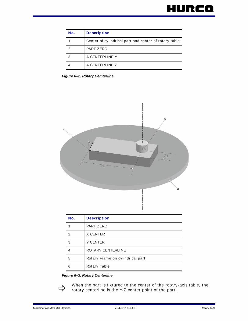
Machine WinMax Mill Options 704-0116-410 Rotary 6-9
Figure 6–2. Rotary Cemterline
Figure 6–3. Rotary Centerline
No. Description
1 Center of cylindrical part and center of rotary table
2 PART ZERO
3 A CENTERLINE Y
4 A CENTERLINE Z
No. Description
1 PART ZERO
2 X CENTER
3 Y CENTER
4 ROTARY CENTERLINE
5 Rotary Frame on cylindrical part
6 Rotary Table
When the part is fixtured to the center of the rotary-axis table, the rotary centerline is the Y-Z center point of the part.

6 - 10 Rotary 704-0116-410 Machine WinMax Mill Options
Rotary Part ProgrammingPart program type is dependent upon machine configuration:
• Rotary A—4-axis rotary machining
• Rotary A Tilt B—4-axis rotary and 5-axis rotary or tilt machining
• Tilt A Rotary C—4-axis rotary and 5-axis rotary or tilt machining on trunion table machines
• Rotary B—4-axis rotary machining on horizontal machines
• Tilt B Rotary C—4-axis rotary and 5-axis rotary or tilt machining on SR machines
• Universal—all axis configurations and machines
See Configuration of Hurco Machining Centers, on page 6 - 3 for information about setting the program type.
The following sections contain details about the program blocks for each configuration:
Rotary A and Rotary A Tilt B Configuration . . . . . . . . . . . . . . . . . . . . . . . . . 6 - 14
Tilt A Rotary C Configuration . . . . . . . . . . . . . . . . . . . . . . . . . . . . . . . . . . . 6 - 19
Rotary B Configuration . . . . . . . . . . . . . . . . . . . . . . . . . . . . . . . . . . . . . . . 6 - 24
Tilt B Rotary C Configuration . . . . . . . . . . . . . . . . . . . . . . . . . . . . . . . . . . . 6 - 27
Universal Rotary Configuration . . . . . . . . . . . . . . . . . . . . . . . . . . . . . . . . . . 6 - 32
Rotary New Block
Rotary New Block is the same for all configurations. When you select the Rotary softkey a new data block will appear with the following softkeys:
• Rotary Position—moves all axes, including the rotary axis. See Rotary Position Block, on page 6 - 11.
• Rotary Milling—access the Rotary Lines and Arcs, Circle, Frame, and True-Type Font data blocks. See Rotary Milling New Block, on page 6 - 12.
• Rotary Patterns—access the Rotary Pattern Loop, Rotary Pattern Locations, Rectangular, Mirror, and Transform Plane data blocks to repeat a rotary feature on a cylinder. See Rotary Patterns, on page 6 - 12.
• Rotary Parameters—define the parameters of the cylinder. See Rotary Parameters, on page 6 - 13.
Tool changes are completed before each rotary data block is executed. The tool change will be automatic or the machine will prompt for manual insertion of the tool specified in the data block.
Refer to Example Programs, on page 6 - 43 for sample part programs.

Machine WinMax Mill Options 704-0116-410 Rotary 6-11
Rotary Position Block
A Rotary Position data block is used to move the machine’s axes to a specific location at Rapid feedrate. A new Rotary Position data block is required each time the rotary-axis must be repositioned in the part program.
The tool will move to the Retract Plane, Safety Plane, or Home Z position before the table rotates into position each time a Rotary Position data block with rotary-axis positioning is executed in a Conversational part program.
Rotary Position Block fields are dependent upon machine axis configuration. Fields for all configurations except Universal are listed below. See Rotary Position Block, on page 6 - 32 for Universal Rotary Position block fields.
• Stop—when set to Yes, pauses program execution after the Rotary Position data block is executed. To restart the program, press the Start Cycle console button.
• X Position—X-axis coordinate relative to Part Zero X.
• Y Position—Y-axis coordinate relative to Part Zero Y.
• A Angle, B Angle, or C Angle—rotary-axis coordinate (angle) relative to Part Zero A, Part Zero B, or Part Zero C, depending on the configuration of your machine.
• Rotary Safety Move—when set to Yes, moves the X and Y axes to the locations defined in X and Y Safety Position fields (described below) before rotary-axis orientation.
• X, Y Safety Position—when the Rotary Safety Move field (described above) is set to Yes, defines the location to which X and Y axes will move before the rotary-axis orients.
• Transform Part Zero—when set to Yes, used to activate Transform Plane for a non-rotary data block machined on multiple sides of a part. Refer to Rotary Transform Plane, on page 6 - 39 for information about using Transform Plane in a Conversational rotary part program.
• Disable Start Location—determines whether or not the machine will reestablish Z Start in the transformed plane. The default value is Yes.
• When set to Yes, the machine keeps track of Z Start, relative to the location of Z in the transformed plane.
• When set to No, the Operator must reestablish part zero for each side of the part that will be machined.
• Use Offset Z—determines whether or not the value in the Offset Z field
A Rotary Position data block should be included as the first data block in a Conversational rotary part program to define the initial orientation of the rotary axis.
Set the Rotary Safety Move field to Yes if there is a potential for collision between the rotary axis and the spindle.
The Transform Plane feature will not function when the Disable Start Location field is set to No.

6 - 12 Rotary 704-0116-410 Machine WinMax Mill Options
on the Part Setup screen will be used by the machine in a transformed plane. The default value is No. Refer to Rotary Part Setup, on page 6 - 8 for information about the Offset Z field.
• When set to Yes, the value in the Offset Z field on the Part Setup screen will be used to establish the part zero coordinate system in Transform Plane operations.
• When set to No, the value in the Offset Z field on the Part Setup screen will be added or subtracted from the Z calibration point during Transform Plane operations.
• Z Move Type—select the level to which Z-axis retracts at the beginning of the Rotary Position data block.
• Z Home—Z-axis will move at Rapid feedrate to the position defined in Z Machine field.
• Z Safety—Z-axis will move at Rapid feedrate to the position defined in the Part Limit Z (+) field on the Part Setup screen.
• Tool—number of the tool that will cut the part, entered on the Tool Setup screen.
Rotary Milling New Block
Rotary Milling New Block is the same for all configurations. These softkeys appear on the Rotary Milling New Block screen:
• Rotary Lines And Arcs—access the Rotary Mill Contour data block to create lines and arcs on a cylinder.
• Rotary Circle—access the Rotary Mill Circle data block to create a circle on a cylinder.
• Rotary Frame—access the Rotary Mill Frame data block to create a frame on a cylinder.
• Rotary True Type Font (available with Universal Rotary configuration only)—access the Rotary True Type font data block to create text on a cylinder.
Rotary Patterns
Rotary patterns allow you to repeat a mill feature (e.g., rotary circle, rotary frame, holes) on the part. These are the softkeys on the Rotary Patterns data block:
• Rotary Loop—repeats a pattern along the X-A plane on a cylindrical part.
• Rotary Locations—repeats a mill feature anywhere on a cylindrical part.
• Rotary Rectangular (available only with Universal Rotary configuration)—repeats a rectangle on a cylindrical part.
• Rotary Mirror (available only with Universal Rotary configuration)—repeats a pattern as a mirror image.
• Transform Plane—activates Transform Plane feature.
• Transform Plane End—ends a Transform Plane operation.

Machine WinMax Mill Options 704-0116-410 Rotary 6-13
• Pattern End—ends a rotary pattern loop or rotary locations operation.
Rotary Parameters
The Rotary Parameters data block is used to set the radius of the cylindrical part and to define the Y Off of Centerline parameter.
These are the fields on the Rotary Parameters data block:
• Cylinder Radius (all configurations except Tilt B Rotary C)—radius of the cylindrical part. If the radius is a negative number, the tool will cut the rotary mill feature (e.g., rotary circle, rotary frame) from the top to bottom.
• Y Off Of Centerline (Rotary A and Rotary A Tilt B configurations only)—determines where the tool will locate the Y coordinate. The default selection is No.
• If set to No, the tool will position the Y coordinate (specified in the A Centerline Y field on the Part Setup screen) directly over the centerline of the rotary axis when cutting a rotary mill feature (e.g., rotary circle, rotary frame).
• If set to Yes, the tool will stay at the current Y coordinate (specified in the A Centerline Y field on the Part Setup screen) when cutting a rotary mill feature (e.g., rotary circle, rotary frame).
• Rotary Centerline X (Tilt B Rotary C configuration only)—the distance from part zero to the vertical axis around which the part will rotate.
• Rotary Centerline Y (Tilt B Rotary C configuration only)—the distance from part zero to the horizontal axis around which the part will rotate.
If the radius of the cylindrical part is not defined in the Rotary Parameters data block and Cutter Compensation is used in rotary lines and arcs, the machine will define the part’s radius as the distance from Z Start to the rotary centerline.

6 - 14 Rotary 704-0116-410 Machine WinMax Mill Options
Rotary A and Rotary A Tilt B ConfigurationRotary Position
The Rotary Position data block is available with multiple rotary configurations; see Rotary Position Block, on page 6 - 11 for an explanation of the softkeys on this screen.
Rotary Lines and Arcs
Rotary line and arc segments are used to create a rotary mill contour. A rotary mill contour is similar to a standard mill contour, except the rotary contour is wrapped around a cylinder.
Start Segment
These are the fields on the Rotary Mill Contour Start Segment data block:
• X Start—X-axis coordinate for first segment’s starting point.
• A Angle—rotary-axis coordinate (angle) for the first segment’s starting point.
• Z Start—point where the Z-axis plunge feedrate begins.
• Z Bottom—the bottom of the finished segment and the location where the Z-axis plunge feedrate ends.
Line Segment
These are the fields on the Rotary Mill Contour Line segment data block:
• X End—X-axis coordinate for ending point of the line.
• A End—rotary-axis coordinate (angle) for the ending point of the line.
• Z End—Z-axis coordinate for the ending point of the line. The Z End value is the depth of the cut at the line end point and is carried forward from the previous segment. Retain the Z End value or type in a new value.
• X Start—X-axis coordinate start point programmed in the previous segment. The value of X Start can be changed only in the segment in which it was created.
• A Start—rotary-axis start point coordinate programmed in the previous segment. The value of A Start can be changed only in the segment in which it was created.
• Z Start—point where the Z-axis plunge feedrate begins.
Arc Segment
These are the fields on the Rotary Mill Contour Arc segment data block:
• Direction—the direction of the arc from the start point, Clockwise or Counter Clockwise.
• X End—X-axis coordinate of the arc’s end point.

Machine WinMax Mill Options 704-0116-410 Rotary 6-15
• A End—rotary-axis coordinate (angle) of the arc’s end point.
• Z END—point where the Z-axis plunge into the cylinder ends.
• X Center—X-axis coordinate of the arc’s center point.
• A Center—rotary-axis coordinate (angle) of the arc’s center point.
• Radius—the radius of the arc, if known.
• Sweep Angle—identifies the angular distance in degrees from the start point of the arc to the end point. The range is -360° to 360°. This field is available when the Arc Sweep Angle option is installed.
• X Start—X-axis coordinate start point programmed in the previous segment. The value of X Start can be changed only in the segment in which it was created.
• A Start—rotary-axis coordinate start point programmed in the previous segment. The value of A Start can be changed only in the segment in which it was created.
• Z Start—Z-axis coordinate start point programming in the previous segment. The value of Z Start can be changed only in the segment in which it was created.
Blend Arc Segment
These are the fields on the Rotary Mill Contour Blend Arc segment data block:
• Radius—the radius of the arc, if known.
• X End—X-axis coordinate of the arc’s end point.
• A End—rotary-axis coordinate (angle) of the arc’s end point.
• X Center—X-axis coordinate of the arc’s center point.
• A Center—rotary-axis coordinate (angle) of the arc’s center point.
• Direction—the direction of the arc from the start point, Clockwise or Counterclockwise.
• X Start—X-axis coordinate start point programmed in the previous segment. The value of X Start can be changed only in the segment in which it was created.
• A Start—rotary-axis coordinate start point programmed in the previous segment. The value of A Start can be changed only in the segment in which it was created.
Mill Contour End Block
A Contour End data block is required to end rotary Mill Contour operations. There are no fields in the Contour End data block.
Rotary Circle
A rotary mill circle is similar to a standard mill circle, except the rotary mill circle is wrapped around a cylinder. These are the fields on the Rotary Mill Circle data block:
These are the Rotary Circle fields for Rotary A and Rotary A Tilt B:

6 - 16 Rotary 704-0116-410 Machine WinMax Mill Options
• X Center—X-axis coordinate for the center point of the circle.
• A Center—rotary-axis coordinate (angle) for the center point of the circle.
• Radius—radius of the milled circle.
• Z Start—location where the Z-axis plunge feedrate begins.
• Z Bottom—location where the Z-axis plunge feedrate ends.
Rotary Frame
A rotary mill frame is similar to a mill frame, except the rotary mill frame is wrapped around a cylinder.
These are the Rotary Mill Frame fields for Rotary A and Rotary A Tilt B:
• X Corner—X-axis coordinate of any one of the four corners of the frame. This corner becomes the reference corner.
• A Corner—rotary-axis coordinate (angle) of the reference corner of the frame.
• X Length—X-axis coordinate measured from the reference corner.
• X Length is positive if the reference corner is at the left side of the rectangle.
• X Length is negative if the reference corner is at the right side of the rectangle.
• A Length—rotary-axis coordinate (angle) from the reference corner.
• A Length is positive if the location of the frame is clockwise from the reference corner.
• A Length is negative if the location of the frame is counter clockwise from the reference corner.
• Z Start—start point for the Z-axis plunge feedrate.
• Z Bottom—end point for the Z-axis plunge feedrate.
• Corner Radius—radius of the reference corner. This value will be the same for all corners of the rotary frame.
Rotary Patterns
The Rotary Patterns data block is available with multiple rotary configurations; see Rotary Patterns, on page 6 - 12 for an explanation of the softkeys on this screen. The specific pattern screens for Rotary A and Rotary A Tilt B are explained below.
Rotary Loop
A rotary loop defines the number and locations a mill feature will be repeated on a cylinder. The initial mill feature is located at part zero and all subsequent copies are at a specific distance along the X-A axis of the cylinder.
These are the Rotary Pattern Loop fields for Rotary A and Rotary A Tilt B:

Machine WinMax Mill Options 704-0116-410 Rotary 6-17
• Number—total number of times the mill feature will be cut on the cylinder.
• X Distance—the distance on the X-axis between each repetition of the mill feature. The right-hand rule determines if X Distance is positive or negative.
• A Distance—the distance (angle) on the rotary-axis between each repetition of the mill feature.
• B Distance (Rotary A Tilt B configuration only)—the distance (angle) on the tilt axis between each repetition of the mill feature.
Rotary Locations
The Rotary Pattern Locations data block is used to create a list of locations of a mill feature repeated on a cylinder. Up to 999 copies can be located anywhere on the part.
Each set of locations listed on the Rotary Patterns Location data block is a specific location on the cylinder, relative to part zero. If you want the mill feature to be cut at part zero, you must define the coordinates of part zero in one of the sets of locations.
These are the Rotary Pattern Locations fields for Rotary A and Rotary A Tilt B:
• X—X-axis coordinate where the mill feature will be located on the part.
• Y—Y-axis coordinate where the mill feature will be located on the part.
• Z—offset for the Z axis. Z is used when a vise or other fixture holds multiple parts at different levels.
A rotary Pattern End data block is required to end the sequence repeated in the Rotary Pattern Loop data block.
Rotary pattern and standard pattern data blocks can be nested (i.e., entirely contained within another pattern). The order of execution for nested rotary pattern and standard pattern data blocks is from the inside to the outside.
This is an example of nested data blocks in a program (the indentations are used illustrate the order of execution; your Conversational part program will not have these indentations).
In the following example, this is the order of execution:
1. Holes and rotary Mill Frame operations contained within the Pattern Loop Rotate data block.
2. Standard Mill Circle operation contained within the Rotary Pattern Loop data block.
Rotary Pattern Loop Standard Mill Circle (or any other rotary or non-rotary data blocks) Pattern Loop Rotate Holes operation Rotary Mill Frame (or other rotary or non-rotary data blocks) Pattern End (ends the Pattern Loop Rotate) Pattern End (ends the Rotary Pattern Loop)
Only one Rotary Position data block is required for nested Rotary Pattern Loop data blocks.

6 - 18 Rotary 704-0116-410 Machine WinMax Mill Options
• A—rotary-axis coordinate (angle) where the mill feature will be located on the part.
• B—tilt-axis coordinate (angle) where the mill feature will be located on the part.
Rotary Transform Plane
The Rotary Transform Plane data block is available with multiple rotary configurations; see Rotary Transform Plane Block, on page 6 - 5 for an explanation of the fields on this screen.
Pattern End
A Pattern End data block is required to end rotary Pattern Loop and rotary Pattern Locations operations. There are no fields in the Pattern End data block.
Rotary Parameters
The Rotary Parameters data block is available with multiple rotary configurations; see
A rotary Pattern End data block is required to end the sequence in the Rotary Pattern Locations data block.
After the rotary Pattern End data block has executed, the orientation of the machine axes will remain at the position defined in the most recent Rotary Position data block.
If the part program continues beyond the Rotary Pattern operation, another Rotary Position data block will be required if the axes must be reoriented to a different position.
• A Rotary Pattern Loop data block only modifies the rotary operations contained within the pattern.
• The subsequent Rotary Position data block defines the orientation of the machine axes after the pattern is executed, and can provide a reference point if Recovery Restart is used.
• If the Rotary Pattern End data block is the last data block of the part program, a subsequent Rotary Position data block is not necessary.
• If a non-rotary operation data block (e.g., holes operation) is used in a rotary loop, a Rotary Position data block is required before the non-rotary operation data block to position the axes before the operation is executed in the loop.

Machine WinMax Mill Options 704-0116-410 Rotary 6-19
Rotary Parameters, on page 6 - 13 for an explanation of the fields on this screen.
Tilt A Rotary C ConfigurationRotary Position
The Rotary Position data block is available with multiple rotary configurations; see Rotary Position Block, on page 6 - 11 for an explanation of the fields on this screen.
Rotary Lines and Arcs
Rotary line and arc segments are used to create a rotary mill contour. A rotary mill contour is similar to a standard mill contour, except the rotary contour is wrapped around a cylinder.
Start Segment
These are the fields on the Rotary AC Mill Contour Start segment data block:
• C Angle—rotary-axis coordinate (angle) for the first segment’s starting point.
• Y Start—Y-axis coordinate for first segment’s starting point.
• Z Start—point where the Z-axis plunge feedrate begins.
• Z Bottom—the bottom of the finished segment and the location where the Z-axis plunge feedrate ends.
Line Segment
These are the fields on the Rotary AC Mill Contour Line segment data block:
• C End—C-axis coordinate for ending point of the line.
• Y End—rotary-axis coordinate (angle) for the ending point of the line.
• Z End—Z-axis coordinate for the ending point of the line. The Z End value is the depth of the cut at the line end point and is carried forward from the previous segment. Retain the Z End value or type in a new value.
• C Start—C-axis coordinate start point programmed in the previous segment. The value of C Start can be changed only in the segment in which it was created.
• Y Start—rotary-axis start point coordinate programmed in the previous segment. The value of Y Start can be changed only in the segment in which it was created.
• Z Start—point where the Z-axis plunge feedrate begins.
Arc Segment
These are the fields on the Rotary AC Mill Contour Arc segment data block:
• Direction—the direction of the arc from the start point, Clockwise or Counter Clockwise.

6 - 20 Rotary 704-0116-410 Machine WinMax Mill Options
• C End—rotary-axis coordinate (angle) of the arc’s end point.
• Y End—Y-axis coordinate of the arc’s end point.
• Z End—point where the Z-axis plunge into the cylinder ends.
• C Center—rotary-axis coordinate (angle) of the arc’s center point.
• Y Center—Y-axis coordinate of the arc’s center point.
• Radius—the radius of the arc, if known.
• Sweep Angle—identifies the angular distance in degrees from the start point of the arc to the end point. The range is -360° to 360°. This field is available when the Arc Sweep Angle option is installed.
• C Start—rotary-axis coordinate start point programmed in the previous segment. The value of C Start can be changed only in the segment in which it was created.
• Y Start—Y-axis coordinate start point programmed in the previous segment. The value of Y Start can be changed only in the segment in which it was created.
• Z Start—Z-axis coordinate start point programming in the previous segment. The value of Z Start can be changed only in the segment in which it was created.
Blend Arc
These are the fields on the Rotary AC Mill Contour Blend Arc segment data block:
• Radius—the radius of the arc, if known.
• C End—rotary-axis coordinate (angle) of the arc’s end point.
• Y End—Y-axis coordinate of the arc’s end point.
• C Center—rotary-axis coordinate (angle) of the arc’s center point.
• Y Center—Y-axis coordinate of the arc’s center point.
• Direction—the direction of the arc from the start point, Clockwise or Counterclockwise.
• C Start—rotary-axis coordinate start point programmed in the previous segment. The value of C Start can be changed only in the segment in which it was created.
• Y Start—Y-axis coordinate start point programmed in the previous segment. The value of Y Start can be changed only in the segment in which it was created.
Mill Contour End Block
A Contour End data block is required to end rotary Mill Contour operations. There are no fields in the Contour End data block.
Rotary Circle
A rotary mill circle is similar to a standard mill circle, except the rotary mill circle is wrapped around a cylinder. These are the fields on the Rotary Mill Circle data block:
Machine WinMax Mill Options 704-0116-410 Rotary 6-21
These are the fields on the Rotary AC Mill Circle data block:
• C Center—rotary-axis coordinate (angle) for the center point of the circle.
• Y Center—Y-axis coordinate for the center point of the circle.
• Radius—radius of the milled circle.
• Z Start—location where the Z-axis plunge feedrate begins.
• Z Bottom—location where the Z-axis plunge feedrate ends.
Rotary Frame
A rotary mill frame is similar to a mill frame, except the rotary mill frame is wrapped around a cylinder.
These are the fields on the Rotary AC Mill Frame data block:
• C Corner—rotary-axis coordinate (angle) of the reference corner of the frame.
• Y Corner—Y-axis coordinate of any one of the four corners of the frame. This corner becomes the reference corner.
• C Length—rotary-axis coordinate (angle) from the reference corner.
• C Length is positive if the location of the frame is clockwise from the reference corner.
• C Length is negative if the location of the frame is counter clockwise from the reference corner.
• Y Length—Y-axis coordinate measured from the reference corner.
• Y Length is positive if the reference corner is at the left side of the rectangle.
• Y Length is negative if the reference corner is at the right side of the rectangle.
• Z Start—start point for the Z-axis plunge feedrate.
• Z Bottom—end point for the Z-axis plunge feedrate.
• Corner Radius—radius of the reference corner. This value will be the same for all corners of the rotary frame.
Rotary Patterns
The Rotary Patterns data block is available with multiple rotary configurations; see Rotary Patterns, on page 6 - 12 for an explanation of the softkeys on this screen. The specific pattern data blocks for Tilt A Rotary C are explained below.
Rotary Loop
A rotary loop defines the number and locations a mill feature will be repeated on a cylinder. The initial mill feature is located at part zero and all subsequent copies are at a specific distance along the X-A axis of the cylinder.
These are the fields on the Rotary Pattern Loop data block for Tilt A Rotary C:

6 - 22 Rotary 704-0116-410 Machine WinMax Mill Options
• Number—total number of times the mill feature will be cut on the cylinder.
• Z Distance—the distance on the Z-axis between each repetition of the mill feature. The right-hand rule determines if Distance is positive or negative.
• A Distance—the distance (angle) on the rotary-axis between each repetition of the mill feature.
• C Distance—the distance (angle) on the tilt axis between each repetition of the mill feature.
Rotary Locations
The Rotary Pattern Locations data block is used to create a list of locations of a mill feature repeated on a cylinder. Up to 999 copies can be located anywhere on the part.
Each set of locations listed on the Rotary Patterns Location data block is a specific location on the cylinder, relative to part zero. If you want the mill feature to be cut at part zero, you must define the coordinates of part zero in one of the sets of locations.
These are the fields on the Rotary Pattern Locations data block for Tilt A Rotary C:
• X—X-axis coordinate where the mill feature will be located on the part.
• Y—Y-axis coordinate where the mill feature will be located on the part.
• Z—offset for the Z axis. Z is used when a vise or other fixture holds multiple parts at different levels.
A rotary Pattern End data block is required to end the sequence repeated in the Rotary Pattern Loop data block.
Rotary pattern and standard pattern data blocks can be nested (i.e., entirely contained within another pattern). The order of execution for nested rotary pattern and standard pattern data blocks is from the inside to the outside.
This is an example of nested data blocks in a program (the indentations are used illustrate the order of execution; your Conversational part program will not have these indentations).
In the following example, this is the order of execution:
1. Holes and rotary Mill Frame operations contained within the Pattern Loop Rotate data block.
2. Standard Mill Circle operation contained within the Rotary Pattern Loop data block.
Rotary Pattern Loop Standard Mill Circle (or any other rotary or non-rotary data blocks) Pattern Loop Rotate Holes operation Rotary Mill Frame (or other rotary or non-rotary data blocks) Pattern End (ends the Pattern Loop Rotate) Pattern End (ends the Rotary Pattern Loop)
Only one Rotary Position data block is required for nested Rotary Pattern Loop data blocks.

Machine WinMax Mill Options 704-0116-410 Rotary 6-23
• A—rotary-axis coordinate (angle) where the mill feature will be located on the part.
• C—rotary-axis coordinate (angle) where the mill feature will be located on the part.
Rotary Transform Plane
The Rotary Transform Plane data block is available with multiple rotary configurations; see Rotary Transform Plane Block, on page 6 - 5 for an explanation of the fields on this screen.
Pattern End
A Pattern End data block is required to end rotary Pattern Loop and rotary Pattern Locations operations. There are no fields in the Pattern End data block.
Rotary Parameters
A rotary Pattern End data block is required to end the sequence in the Rotary Pattern Locations data block.
After the rotary Pattern End data block has executed, the orientation of the machine axes will remain at the position defined in the most recent Rotary Position data block.
If the part program continues beyond the Rotary Pattern operation, another Rotary Position data block will be required if the axes must be reoriented to a different position.
After the rotary Pattern End data block has executed, the orientation of the machine axes will remain at the position defined in the most recent Rotary Position data block.
If the part program continues beyond the Rotary Pattern operation, another Rotary Position data block will be required if the axes must be reoriented to a different position.
• A Rotary Pattern Loop data block only modifies the rotary operations contained within the pattern.
• The subsequent Rotary Position data block defines the orientation of the machine axes after the pattern is executed, and can provide a reference point if Recovery Restart is used.
• If the Rotary Pattern End data block is the last data block of the part program, a subsequent Rotary Position data block is not necessary.
• If a non-rotary operation data block (e.g., holes operation) is used in a rotary loop, a Rotary Position data block is required before the non-rotary operation data block to position the axes before the operation is executed in the loop.

6 - 24 Rotary 704-0116-410 Machine WinMax Mill Options
The Rotay Parameters data block is available with multiple rotary configurations; see Rotary Parameters, on page 6 - 13 for an explanation of the fields on this screen.
Rotary B ConfigurationRotary B configuration is used with horizontal (HTX) machines.
Rotary Position
The Rotary Position data block is available with multiple rotary configurations; see Rotary Position Block, on page 6 - 11 for an explanation of the fields on this screen.
Rotary Milling
For rotary milling programs on an HTX machine, Universal Rotary configuration must be used; see Universal Rotary Configuration, on page 6 - 32.
Rotary Patterns
The Rotary Patterns data block is available with multiple rotary configurations; see Rotary Patterns, on page 6 - 12 for an explanantion of the softkeys on this screen. The specific pattern data blocks for Rotary B configuration are explained below.
Rotary Loop
A rotary loop defines the number and locations a mill feature will be repeated on a cylinder. The initial mill feature is located at part zero and all subsequent copies are at a specific distance along the X-A axis of the cylinder.
These are the fields on the Rotary Pattern Loop data block for Rotary B:
• Number—total number of times the mill feature will be cut on the cylinder.
• Z Distance—the distance on the Z-axis between each repetition of the mill feature. The right-hand rule determines if Distance is positive or negative.
• B Distance —the distance (angle) on the rotary axis between each repetition of the mill feature.
A rotary Pattern End data block is required to end the sequence repeated in the Rotary Pattern Loop data block.

Machine WinMax Mill Options 704-0116-410 Rotary 6-25
Rotary Locations
The Rotary Pattern Locations data block is used to create a list of locations of a mill feature repeated on a cylinder. Up to 999 copies can be located anywhere on the part.
Each set of locations listed on the Rotary Patterns Location data block is a specific location on the cylinder, relative to part zero. If you want the mill feature to be cut at part zero, you must define the coordinates of part zero in one of the sets of locations.
These are the fields on the Rotary Pattern Locations data block for Rotary B:
• X—X-axis coordinate where the mill feature will be located on the part.
• Y—Y-axis coordinate where the mill feature will be located on the part.
• Z—offset for the Z axis. Z is used when a vise or other fixture holds multiple parts at different levels.
• B—rotary-axis coordinate (angle) where the mill feature will be located on the part.
Rotary pattern and standard pattern data blocks can be nested (i.e., entirely contained within another pattern). The order of execution for nested rotary pattern and standard pattern data blocks is from the inside to the outside.
This is an example of nested data blocks in a program (the indentations are used illustrate the order of execution; your Conversational part program will not have these indentations).
In the following example, this is the order of execution:
1. Holes and rotary Mill Frame operations contained within the Pattern Loop Rotate data block.
2. Standard Mill Circle operation contained within the Rotary Pattern Loop data block.
Rotary Pattern Loop Standard Mill Circle (or any other rotary or non-rotary data blocks) Pattern Loop Rotate Holes operation Rotary Mill Frame (or other rotary or non-rotary data blocks) Pattern End (ends the Pattern Loop Rotate) Pattern End (ends the Rotary Pattern Loop)
Only one Rotary Position data block is required for nested Rotary Pattern Loop data blocks.
A rotary Pattern End data block is required to end the sequence in the Rotary Pattern Locations data block.

6 - 26 Rotary 704-0116-410 Machine WinMax Mill Options
Rotary Transform Plane
The Rotary Transform Plane data block is available with multiple rotary configurations; see Rotary Transform Plane Block, on page 6 - 5 for an explanation of the fields on this screen.
Pattern End
A Pattern End data block is required to end rotary Pattern Loop and rotary Pattern Locations operations. There are no fields in the Pattern End data block.
Rotary Parameters
The Rotary Parameters data block is available with multiple rotary configurations; see Rotary Parameters, on page 6 - 13 for an explanation of the fields on this screen.
After the rotary Pattern End data block has executed, the orientation of the machine axes will remain at the position defined in the most recent Rotary Position data block.
If the part program continues beyond the Rotary Pattern operation, another Rotary Position data block will be required if the axes must be reoriented to a different position.
• A Rotary Pattern Loop data block only modifies the rotary operations contained within the pattern.
• The subsequent Rotary Position data block defines the orientation of the machine axes after the pattern is executed, and can provide a reference point if Recovery Restart is used.
• If the Rotary Pattern End data block is the last data block of the part program, a subsequent Rotary Position data block is not necessary.
• If a non-rotary operation data block (e.g., holes operation) is used in a rotary loop, a Rotary Position data block is required before the non-rotary operation data block to position the axes before the operation is executed in the loop.

Machine WinMax Mill Options 704-0116-410 Rotary 6-27
Tilt B Rotary C ConfigurationRotary Position
The Rotary Position data block is available with multiple rotary configurations; see Rotary Position Block, on page 6 - 11 for an explanation of the fields onthis screen.
Rotary Lines and Arcs
Rotary line and arc segments are used to create a rotary mill contour. A rotary mill contour is similar to a standard mill contour, except the rotary contour is wrapped around a cylinder.
Start Segment
These are the fields on the Rotary BC Mill Contour Start segment data block:
• Z Start—Z-axis coordinate for first segment’s starting point.
• C Angle—rotary-axis coordinate (angle) for the first segment’s starting point.
• Radius Start—point where the Z-axis plunge feedrate begins.
• Radius Bottom—the bottom of the finished segment and the location where the Z-axis plunge feedrate ends.
Line Segment
These are the fields on the Rotary BC Mill Contour Line segment data block:
• Z End—Z-axis coordinate for the ending point of the line. The Z End value is the depth of the cut at the line end point and is carried forward from the previous segment. Retain the Z End value or type in a new value.
• C End—C-axis coordinate for ending point of the line.
• Radius End—rotary-axis coordinate (angle) for the ending point of the line.
• Z Start—point where the Z-axis plunge feedrate begins.
• C Start—C-axis coordinate start point programmed in the previous segment. The value of C Start can be changed only in the segment in which it was created.
• Radius Start—rotary-axis start point coordinate programmed in the previous segment. The value of Radius Start can be changed only in the segment in which it was created.
Arc Segment
These are the fields on the Rotary BC Mill Contour Arc segment data block:
• Direction—the direction of the arc from the start point, Clockwise or Counter Clockwise.
• Z End—point where the Z-axis plunge into the cylinder ends.
• C End—rotary-axis coordinate (angle) of the arc’s end point.

6 - 28 Rotary 704-0116-410 Machine WinMax Mill Options
• Radius End—Y-axis coordinate of the arc’s end point.
• Z Center—Z-axis coordinate of the arc’s center point.
• C Center—rotary-axis coordinate (angle) of the arc’s center point.
• Arc Radius—the radius of the arc, if known.
• Sweep Angle—identifies the angular distance in degrees from the start point of the arc to the end point. The range is -360° to 360°. This field is available when the Arc Sweep Angle option is installed.
• Z Start—Z-axis coordinate start point programming in the previous segment. The value of Z Start can be changed only in the segment in which it was created.
• C Start—rotary-axis coordinate start point programmed in the previous segment. The value of C Start can be changed only in the segment in which it was created.
• Radius Start—Y-axis coordinate start point programmed in the previous segment. The value of Radius Start can be changed only in the segment in which it was created.
Blend Arc Segment
These are the fields on the Rotary BC Mill Contour Blend Arc segment data block:
• Arc Radius—the radius of the arc, if known.
• Z End—Z-axis coordinate of the arc’s end point.
• C End—rotary-axis coordinate (angle) of the arc’s end point.
• Z Center—Z-axis coordinate of the arc’s center point.
• C Center—rotary-axis coordinate (angle) of the arc’s center point.
• Direction—the direction of the arc from the start point, Clockwise or Counterclockwise.
• Z Start—Z-axis coordinate start point programmed in the previous segment. The value of Z Start can be changed only in the segment in which it was created.
• C Start—rotary-axis coordinate start point programmed in the previous segment. The value of C Start can be changed only in the segment in which it was created.
Mill Contour End Block
A Contour End data block is required to end rotary Mill Contour operations. There are no fields in the Contour End data block.
Rotary Circle
A rotary mill circle is similar to a standard mill circle, except the rotary mill circle is wrapped around a cylinder. These are the fields on the Rotary Mill Circle data block:
These are the fields on the Rotary BC Circle data block:
• Z Center—Z-axis coordinate for the center point of the circle.

Machine WinMax Mill Options 704-0116-410 Rotary 6-29
• C Center—rotary-axis coordinate (angle) for the center point of the circle.
• Radius—radius of the milled circle.
• Radius Start—location where the Z-axis plunge feedrate begins.
• Radius Bottom—location where the Z-axis plunge feedrate ends.
Rotary Frame
A rotary mill frame is similar to a mill frame, except the rotary mill frame is wrapped around a cylinder.
These are the fields on the Rotary BC Mill Frame data block:
• Z Corner—Z-axis coordinate of any one of the four corners of the frame. This corner becomes the reference corner.
• C Corner—rotary-axis coordinate (angle) of the reference corner of the frame.
• Z Length—Z-axis coordinate measured from the reference corner.
• Z Length is positive if the reference corner is at the left side of the rectangle.
• Z Length is negative if the reference corner is at the right side of the rectangle.
• C Length—rotary-axis coordinate (angle) from the reference corner.
• C Length is positive if the location of the frame is clockwise from the reference corner.
• C Length is negative if the location of the frame is counter clockwise from the reference corner.
• Radius Start—start point for the Z-axis plunge feedrate.
• Radius Bottom—end point for the Z-axis plunge feedrate.
• Corner Radius—radius of the reference corner. This value will be the same for all corners of the rotary frame.
Rotary Patterns
The Rotary Patterns data block is available with multiple rotary configurations; see Rotary Patterns, on page 6 - 12 for an explanation of the softkeys on this screen. The specific pattern data blocks for Tilt B Rotary C configuration are explained below.
Rotary Loop
A rotary loop defines the number and locations a mill feature will be repeated on a cylinder. The initial mill feature is located at part zero and all subsequent copies are at a specific distance along the X-A axis of the cylinder.
These are the fields on the Rotary Pattern Loop data block for Tilt B Rotary C:
A rotary Pattern End data block is required to end the sequence repeated in the Rotary Pattern Loop data block.
6 - 30 Rotary 704-0116-410 Machine WinMax Mill Options
• Number—total number of times the mill feature will be cut on the cylinder.
• Z Distance—the distance on the Z-axis between each repetition of the mill feature. The right-hand rule determines if Distance is positive or negative.
• C Distance —the distance (angle) on the C-axis between each repetition of the mill feature.
Rotary Locations
The Rotary Pattern Locations data block is used to create a list of locations of a mill feature repeated on a cylinder. Up to 999 copies can be located anywhere on the part.
Each set of locations listed on the Rotary Patterns Location data block is a specific location on the cylinder, relative to part zero. If you want the mill feature to be cut at part zero, you must define the coordinates of part zero in one of the sets of locations.
These are the fields on the Rotary Pattern Locations data block for Tilt B Rotary C:
• X—X-axis coordinate where the mill feature will be located on the part.
• Y—Y-axis coordinate where the mill feature will be located on the part.
• Z—offset for the Z axis. Z is used when a vise or other fixture holds multiple parts at different levels.
• B—rotary-axis coordinate (angle) where the mill feature will be located on the part.
• C—rotary-axis coordinate (angle) where the mill feature will be located on the part.
Rotary pattern and standard pattern data blocks can be nested (i.e., entirely contained within another pattern). The order of execution for nested rotary pattern and standard pattern data blocks is from the inside to the outside.
This is an example of nested data blocks in a program (the indentations are used illustrate the order of execution; your Conversational part program will not have these indentations).
In the following example, this is the order of execution:
1. Holes and rotary Mill Frame operations contained within the Pattern Loop Rotate data block.
2. Standard Mill Circle operation contained within the Rotary Pattern Loop data block.
Rotary Pattern Loop Standard Mill Circle (or any other rotary or non-rotary data blocks) Pattern Loop Rotate Holes operation Rotary Mill Frame (or other rotary or non-rotary data blocks) Pattern End (ends the Pattern Loop Rotate) Pattern End (ends the Rotary Pattern Loop)
Only one Rotary Position data block is required for nested Rotary Pattern Loop data blocks.

Machine WinMax Mill Options 704-0116-410 Rotary 6-31
Rotary Transform Plane
The Rotary Transform Plane data block is available with multiple rotary configurations; see Rotary Transform Plane Block, on page 6 - 5 for an explanation of the fields on this screen.
Pattern End
A Pattern End data block is required to end rotary Pattern Loop and rotary Pattern Locations operations. There are no fields in the Pattern End data block.
Rotary Parameters
The Rotary Parameters data block is available with multiple rotary configurations; see Rotary Parameters, on page 6 - 13 for an explanation of the field on this screen.
A rotary Pattern End data block is required to end the sequence in the Rotary Pattern Locations data block.
After the rotary Pattern End data block has executed, the orientation of the machine axes will remain at the position defined in the most recent Rotary Position data block.
If the part program continues beyond the Rotary Pattern operation, another Rotary Position data block will be required if the axes must be reoriented to a different position.
• A Rotary Pattern Loop data block only modifies the rotary operations contained within the pattern.
• The subsequent Rotary Position data block defines the orientation of the machine axes after the pattern is executed, and can provide a reference point if Recovery Restart is used.
• If the Rotary Pattern End data block is the last data block of the part program, a subsequent Rotary Position data block is not necessary.
• If a non-rotary operation data block (e.g., holes operation) is used in a rotary loop, a Rotary Position data block is required before the non-rotary operation data block to position the axes before the operation is executed in the loop.

6 - 32 Rotary 704-0116-410 Machine WinMax Mill Options
Universal Rotary ConfigurationRotary Position Block
A Rotary Position data block is used to move the machine’s axes to a specific location at Rapid feedrate. A new Rotary Position data block is required each time the rotary-axis must be repositioned in the part program.
The tool will move to the Retract Plane, Safety Plane, or Home Z position before the table rotates into position each time a Rotary Position data block with rotary-axis positioning is executed in a Conversational part program.
These are the fields on the Rotary Position data block:
• Stop—when set to Yes, pauses program execution after the Rotary Position data block is executed. To restart the program, press the Start Cycle console button.
First Move (Z Retract)
• Retract Type—select the Z level to which Z-axis retracts at the beginning of the Rotary Position data block.
• Z Home—Z-axis will move at Rapid feedrate to the position defined in Z Machine field.
• Z Position—Z-axis will move at Rapid feedrate to the position entered in the Z Position field.
• Z Position—the position to which Z-axis retracts when Z Position is selected for the Retract Type.
Second Move
• Enable—specify YES to enable axis movement
• X Position—defines the location to which the X axis will move before the rotary-axis orients.
• Y Position—defines the location to which the Y axis will move before the rotary-axis orients.
Third Move (End Position)
• X Position—X-axis coordinate relative to Part Zero X. Enabled when the Enable field is set to YES.
• Y Position—Y-axis coordinate relative to Part Zero X. Enabled when the Enable field is set to YES.
• IV Angle—rotary-axis coordinate (angle) relative to Part Zero A or Part Zero C, depending on the configuration of your machine. Enabled when the Enable field is set to YES.
A Rotary Position data block should be included as the first data block in a Conversational rotary part program to define the initial orientation of the rotary axis.

Machine WinMax Mill Options 704-0116-410 Rotary 6-33
• V Angle—rotary-axis coordinate (angle) relative to Part Zero A or Part Zero C, depending on the configuration of your machine. Enabled when the Enable field is set to YES.
Rotary Lines and Arcs
Rotary line and arc segments are used to create a rotary mill contour. A rotary mill contour is similar to a standard mill contour, except the rotary contour is wrapped around a cylinder.
Start Segment
These are the fields on the Universal Rotary Mill Contour Start segment data block:
• Axis Start—axis coordinate for first segment’s starting point.
• Angle Start—rotary-axis coordinate (angle) for the first segment’s starting point.
• Radius Start—point where the Z-axis plunge feedrate begins.
• Radius Bottom—the bottom of the finished segment and the location where the Z-axis plunge feedrate ends.
Line Segment
These are the fields on the Universal Rotary Mill Contour line segment data block:
• Axis End—axis coordinate for the ending point of the line. The Axis End value is the depth of the cut at the line end point and is carried forward from the previous segment. Retain the Axis End value or type in a new value.
• Angle End—axis coordinate for ending point of the line.
• Radius End—rotary-axis coordinate (angle) for the ending point of the line.
• Axis Start—axis coordinate start point programmed in the previous segment. The value of Axis Start can be changed only in the segment in which it was created.
• Angle Start—point where the Z-axis plunge feedrate begins.
• Radius Start—rotary-axis start point coordinate programmed in the previous segment. The value of Radius Start can be changed only in the segment in which it was created.
Arc Segment
These are the fields on the Universal Rotary Mill Contour Arc segment data block:
• Direction—the direction of the arc from the start point, Clockwise or Counter Clockwise.
• Axis End—rotary-axis coordinate (angle) of the arc’s end point.
• Angle End—Y-axis coordinate of the arc’s end point.
• Radius End—point where the Z-axis plunge into the cylinder ends.
• Axis Center—Z-axis coordinate of the arc’s center point.
• Angle Center—rotary-axis coordinate (angle) of the arc’s center point.
6 - 34 Rotary 704-0116-410 Machine WinMax Mill Options
• Radius—the radius of the arc, if known.
• Sweep Angle—identifies the angular distance in degrees from the start point of the arc to the end point. The range is -360° to 360°. This field is available when the Arc Sweep Angle option is installed.
• Axis Start—axis coordinate start point programmed in the previous segment. The value of Axis Start can be changed only in the segment in which it was created.
• Angle Start—rotary-axis coordinate start point programmed in the previous segment. The value of Angle Start can be changed only in the segment in which it was created.
• Radius Start—Z-axis coordinate start point programming in the previous segment. The value of Z Start can be changed only in the segment in which it was created.
Blend Arc Segment
These are the fields on the Universal Rotary Mill Contour Blend Arc segment data block:
• Direction—the direction of the arc from the start point, Clockwise or Counter Clockwise.
• Axis End—rotary-axis coordinate (angle) of the arc’s end point.
• Angle End—Y-axis coordinate of the arc’s end point.
• Axis Center—Z-axis coordinate of the arc’s center point.
• Angle Center—rotary-axis coordinate (angle) of the arc’s center point.
• Radius—the radius of the arc, if known.
• Axis Start—axis coordinate start point programmed in the previous segment. The value of Axis Start can be changed only in the segment in which it was created.
• Angle Start—rotary-axis coordinate start point programmed in the previous segment. The value of Angle Start can be changed only in the segment in which it was created.
Rotary Circle
A rotary mill circle is similar to a standard mill circle, except the rotary mill circle is wrapped around a cylinder. These are the fields on the Rotary Mill Circle data block:
These are the fields on the Universal Rotary Mill Circle data block:
• Axis Center—Z-axis coordinate for the center point of the circle.
• Angle Center—rotary-axis coordinate (angle) for the center point of the circle.
• Radius—radius of the milled circle.
• Radius Start—location where the Z-axis plunge feedrate begins.
• Radius Bottom—location where the Z-axis plunge feedrate ends.

Machine WinMax Mill Options 704-0116-410 Rotary 6-35
Rotary Frame
A rotary mill frame is similar to a mill frame, except the rotary mill frame is wrapped around a cylinder.
These are the fields on the Universal Rotary Mill Frame data block:
• Axis Start—axis coordinate of any one of the four corners of the frame. This corner becomes the reference corner.
• Angle Start—rotary-axis coordinate (angle) of the reference corner of the frame.
• Axis Length—axis coordinate measured from the reference corner.
• Axis Length is positive if the reference corner is at the left side of the rectangle.
• Axis Length is negative if the reference corner is at the right side of the rectangle.
• Angle Length—rotary-axis coordinate (angle) from the reference corner.
• Angle Length is positive if the location of the frame is clockwise from the reference corner.
• Angle Length is negative if the location of the frame is counter clockwise from the reference corner.
• Radius Start—start point for the Z-axis plunge feedrate.
• Radius Bottom—end point for the Z-axis plunge feedrate.
• Corner Radius—radius of the reference corner. This value will be the same for all corners of the rotary frame.
Rotary True Type Font
Rotary True Type Font is available with Universal Rotary configuration only. These are the True Type Lettering fields:
• Axis Ref Location—the location of the reference point in the text:
• Start of text
• End of text
• center of text
• Axis Reference—the reference coordinate of the Sizing Box.
• Angle Ref Location—the location of the reference point in the text:
• Bottom of text
• Top of text
• Center of text
• Angle Reference—the reference coordinate of the Sizing Box.
• Text Width— the width of the text.
• Text Height—the height of the text.

6 - 36 Rotary 704-0116-410 Machine WinMax Mill Options
• Text—the text to be milled.
• Radius Start—the Z coordinate at which plunge feedrate begins.
• Radius Bottom—Z bottom coordinate
• Orientation—the angle to which the text should be rotated.
• Mapping Mode—specifies the height dimension of the lettering:
• Body Only—defines the height of the body of the lettering. Ascenders and descenders are calculated automatically.
• Descended—defines the height of the body and descenders of the lettering. Ascenders are calculated automatically.
• Ascended—defines the height of the body and ascenders of the lettering. Descenders are calculated automatically.
• Full Font—defines the height of the body, ascenders, and descenders of the lettering. No part of the lettering is calculated automatically.
Figure 6–4. Y Mapping
• Font—the lettering font. The font selection dialog box is opened with the Select New Font softkey, when the cursor is in the Text field.
1 Body only
2 Descended
3 Ascended
4 Full font
Available Fonts for Mill True-Type Lettering
Arial (default)
Arial Black
Comic Sans MS
Courier New
Euro Sign
Frame5 Font
Franklin Gothic Medium
Georgia
Impact
Lucida Console
Lucida Sans Unicode
Marlett
Microsoft Sans Serif
Palatino Linotype
Sylfaen
Tahoma
Times New Roman
Trebuchet MS
Verdana
Webdings
Wingdings
ZWAdobeF

Machine WinMax Mill Options 704-0116-410 Rotary 6-37
• Outside Cylinder—specifies if text is milled on the inside or outside of a cylinder:
• Yes—text is milled on the outside of a cylinder.
• No—text is milled on the inside of a cylinder.
Rotary Patterns
The Rotary Patterns data block is available with multiple rotary configurations; see Rotary Patterns, on page 6 - 12 for an explanation of the softkeys on this screen. The specific pattern data blocks for Universal Rotary are explained below.
Rotary Loop
A rotary loop defines the number and locations a mill feature will be repeated on a cylinder. The initial mill feature is located at part zero and all subsequent copies are at a specific distance along the X-A axis of the cylinder.
These are the fields on the Universal Rotary Pattern Loop data block:
• Number—total number of times the mill feature will be cut on the cylinder.
• Axis Distance—the distance on the X-axis between each repetition of the mill feature. The right-hand rule determines if Distance is positive or negative.
• Angle Distance—the distance (angle) on the rotary-axis between each repetition of the mill feature.
A rotary Pattern End data block is required to end the sequence repeated in the Rotary Pattern Loop data block.
6 - 38 Rotary 704-0116-410 Machine WinMax Mill Options
Rotary Locations
The Rotary Pattern Locations data block is used to create a list of locations of a mill feature repeated on a cylinder. Up to 999 copies can be located anywhere on the part.
Each set of locations listed on the Rotary Patterns Location data block is a specific location on the cylinder, relative to part zero. If you want the mill feature to be cut at part zero, you must define the coordinates of part zero in one of the sets of locations.
These are the fields on the Universal Rotary Pattern Locations data block:
• Axis—X-axis coordinate where the mill feature will be located on the part.
• Angle—Y-axis coordinate where the mill feature will be located on the part.
Rotary pattern and standard pattern data blocks can be nested (i.e., entirely contained within another pattern). The order of execution for nested rotary pattern and standard pattern data blocks is from the inside to the outside.
This is an example of nested data blocks in a program (the indentations are used illustrate the order of execution; your Conversational part program will not have these indentations).
In the following example, this is the order of execution:
1. Holes and rotary Mill Frame operations contained within the Pattern Loop Rotate data block.
2. Standard Mill Circle operation contained within the Rotary Pattern Loop data block.
Rotary Pattern Loop Standard Mill Circle (or any other rotary or non-rotary data blocks) Pattern Loop Rotate Holes operation Rotary Mill Frame (or other rotary or non-rotary data blocks) Pattern End (ends the Pattern Loop Rotate) Pattern End (ends the Rotary Pattern Loop)
Only one Rotary Position data block is required for nested Rotary Pattern Loop data blocks.
A rotary Pattern End data block is required to end the sequence in the Rotary Pattern Locations data block.
After the rotary Pattern End data block has executed, the orientation of the machine axes will remain at the position defined in the most recent Rotary Position data block.
If the part program continues beyond the Rotary Pattern operation, another Rotary Position data block will be required if the axes must be reoriented to a different position.
Machine WinMax Mill Options 704-0116-410 Rotary 6-39
Rotary Rectangular
Rotary Rectangular Pattern Block is available only with the Universal Rotary configuration. Fields are:
• Axis Number—the number of times the programmed routine will be repeated along a line parallel to the rotary axis.
• Angle Number—the number of times the programmed routine will be repeated along the rotary axis.
• Axis Distance—the distance between the patterns parallel to the rotary axis.
• Angle Distance—the distance between the patterns along the rotary axis.
Rotary Mirror
Rotary Mirror Pattern Block is available only with the Universal Rotary configuration. Fields are:
• Keep Original—indicate if you want to machine the original pattern in addition to the mirrored pattern.
• Yes—machine original pattern
• No—machine only mirrored pattern
• Cylinder Angle—the coordinate of a point on the mirror line.
• Cylinder Axis—the coordinate of a point on the mirror line.
• Angle—the orientation of the mirror line which passes through the point defined above (measured in XY from 3 o’clock).
Rotary Transform Plane
Transform Plane is used in a Conversational rotary program to position part zero for a non-rotary data block to any orientation of any plane of your rotary- or tilt-axis machine. For example, use Transform Plane when you want to repeat a non-rotary feature (e.g., mill contour, holes) on multiple sides of a part.
Rotary Transform Plane End
The Transform Plane End block ends the Transform Plane operation.
After the Transform Plane End data block has executed, the orientation of the part will remain at the position defined in the most recent Rotary Position data block.
If the part program continues beyond the Transform Plane operation, another Rotary Position data block will be required if the part must be reorientated to a different position.

6 - 40 Rotary 704-0116-410 Machine WinMax Mill Options
Pattern End
A Pattern End data block is required to end rotary Pattern Loop and rotary Pattern Locations operations. There are no fields in the Pattern End data block.
Rotary ParametersThe Rotary Orientation field defines the axis configuration: Rotary A/AB, Rotary B, Rotary AC, Rotary BC, and User Defined. User Defined orientation requires the Axis of Rotation (Cylinder Axis vector) and Zero Angle vector. The Zero Angle vector describes the zero-degree Cylindrical Point vector direction with respect to the current coordinate system. These vectors must be perpendicular otherwise the control will throw an error. Other Rotary Orientation selections (Rotary A/AB, Rotary B, Rotary AC, Rotary BC) are available to automatically configure the Axis of Rotation and Zero Angle vectors to describe rotary features for Hurco's current program type configurations.
After the rotary Pattern End data block has executed, the orientation of the machine axes will remain at the position defined in the most recent Rotary Position data block.
If the part program continues beyond the Rotary Pattern operation, another Rotary Position data block will be required if the axes must be reoriented to a different position.
• A Rotary Pattern Loop data block only modifies the rotary operations contained within the pattern.
• The subsequent Rotary Position data block defines the orientation of the machine axes after the pattern is executed, and can provide a reference point if Recovery Restart is used.
• If the Rotary Pattern End data block is the last data block of the part program, a subsequent Rotary Position data block is not necessary.
• If a non-rotary operation data block (e.g., holes operation) is used in a rotary loop, a Rotary Position data block is required before the non-rotary operation data block to position the axes before the operation is executed in the loop.

Machine WinMax Mill Options 704-0116-410 Rotary 6-41
Calculating X- and Z-Axis Positions After a Tilt-Axis MoveThe initial location of a point on a cylindrical workpiece will be at different X and Z coordinates after the tilt-axis is moved into position. Some tilt-axis tables have part zero calibrated at 0° vertical, and some have part zero calibrated at 0° horizontal. Use the formulas below that correspond to the part zero calibration of your machine.
Part Zero Calibrated at Zero Degree Vertical
Follow these steps to determine the relative location of X and Z when the tilt-axis is positioned at 0° in the vertical plane (as shown in the figure below):
1. Use the formula L = Z1-Z3 to calculate L, the distance between the point’s initial location and the location of the same point after the workpiece is positioned to a known angle on the tilt-axis.
2. Use the formula X2 = L sinB to determine the location of X2, the location of the X coordinate on the workpiece after the tilt-axis has been moved.
3. Use the formula Z2 = L - (L cosB) to determine Z2, the location of the Z coordinate on the workpiece after the tilt-axis has been moved.
Figure 6–5. Vertical Tilt-Axis Example
1 Z1
2 Z2
3 B (tilt-axis) = 0°
4 Z3
5 L
6 X2

6 - 42 Rotary 704-0116-410 Machine WinMax Mill Options
Part Zero Calibrated at Zero Degree Horizontal
Follow these steps to determine the relative location of X and Z when the tilt-axis is positioned at 0º in the horizontal plane (as shown in the figure below).
1. Use the formula L = X1-X3 to calculate L, the distance between the point’s initial location and the location of the same point after the workpiece is positioned to a known angle on the tilt-axis.
2. Use the formula X2 = L- (L cosB) to determine the location of X2, the location of the X coordinate on the workpiece after the tilt-axis has been moved.
3. Use the formula Z2 = L sinB to determine the location of Z2, the location of the Z coordinate on the workpiece after the tilt-axis has been moved.
Figure 6–6. Horizontal Tilt-Axis Example
1 X1
2 X2
3 B (tilt-axis) = 0°
4 X3
5 L
6 Z2

Machine WinMax Mill Options 704-0116-410 Rotary 6-43
Example ProgramsRotary Programming Examples
The figure below shows a Rotary Mill Frame created on a cylinder.
Figure 6–7. Rotary Mill Frame Part Drawing (cylinder shown for reference)
This is a summary of the program used to create the part shown in the figure above:
No. Description
1 PART ZERO
2 A LENGTH (arrow indicates positive axis movement)
3 Reference Corner (X Corner/A Corner)
4 X LENGTH

6 - 44 Rotary 704-0116-410 Machine WinMax Mill Options
Table 6–1. Rotary Mill Frame Part Program Summary
The figure below shows a helix created from a cylinder using Rotary Mill Contour. The threads shown in the drawing below are on the outside of the cylinder.
Figure 6–8. Threading Part Drawing (cylinder shown for reference)
DB Data Block/Field Name Value Notes
1 ROTARY PARAMETERS Defines the cylinder.
CYLINDER RADIUS 2.0000
2 ROTARY POSITION Moves the machine axes.
X 0.0000 X-axis position for the rotary operation.
Y 31.0352 Y-axis position for the rotary operation.
A 0.000 Rotary-axis angle for the rotary operation.
3 ROTARY MILL FRAME
X CORNER -1.0000 X-axis coordinate for Reference Corner.
A CORNER -90.000 Rotary-axis angle for Reference Corner.
X LENGTH 2.000 X coordinate length from Reference Corner.
A LENGTH 75.00 Rotary-axis length from Reference Corner.
CORNER RADIUS 0.2500 Radius of each of the corners.
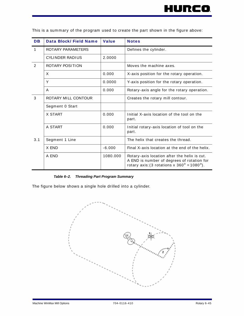
Machine WinMax Mill Options 704-0116-410 Rotary 6-45
This is a summary of the program used to create the part shown in the figure above:
Table 6–2. Threading Part Program Summary
The figure below shows a single hole drilled into a cylinder.
DB Data Block/Field Name Value Notes
1 ROTARY PARAMETERS Defines the cylinder.
CYLINDER RADIUS 2.0000
2 ROTARY POSITION Moves the machine axes.
X 0.000 X-axis position for the rotary operation.
Y 0.0000 Y-axis position for the rotary operation.
A 0.000 Rotary-axis angle for the rotary operation.
3 ROTARY MILL CONTOUR Creates the rotary mill contour.
Segment 0 Start
X START 0.000 Initial X-axis location of the tool on the part.
A START 0.000 Initial rotary-axis location of tool on the part.
3.1 Segment 1 Line The helix that creates the thread.
X END -6.000 Final X-axis location at the end of the helix.
A END 1080.000 Rotary-axis location after the helix is cut. A END is number of degrees of rotation for rotary axis:(3 rotations x 360° =1080°).

6 - 46 Rotary 704-0116-410 Machine WinMax Mill Options
Figure 6–9. Single Hole Part Drawing (cylinder shown for reference)
This is a summary of the program used to create the part shown in the figure above:
Table 6–3. Hole Part Program Summary
The figure below shows a pattern of holes on a cylinder created with a Rotary Pattern Loop.
No. Description
1 PART ZERO
2 A (arrow indicates positive axis movement)
DB Data Block/Field Name Value Notes
1 ROTARY PARAMETERS Defines the cylinder.
CYLINDER RADIUS 2.0000
2 ROTARY POSITION Moves the machine axes.
X -1.5000 X-axis position for the hole location on the cylinder. X is -1.5000 because the part must move in the negative direction from part zero.
Y 0.0000 Y-axis position for the hole location on the cylinder.
A 30.000 Rotary-axis angle for the hole location on the cylinder.
3 HOLES
3.1 DRILL Specifies the hole operations (same as for 3-axis milling, drilling, tap etc. operations).

Machine WinMax Mill Options 704-0116-410 Rotary 6-47
Figure 6–10. Rotary Pattern Loop Part Drawing (cylinder shown for reference)
This is a summary of the program used to create the part shown in the figure above:
Table 6–4. Rotary Pattern Loop Part Program Summary
The figure below shows a rectangular workpiece created on a WinMax Mill 4-axis machine using the Transform Plane feature. Standard mill contour and Rotary Position data blocks were used to remove the material from the cylinder to make the rectangular part.
No. Description
1 PART ZERO
2 A DISTANCE (arrow indicates positive axis movement)
3 X DISTANCE
DB Data Block/Field Name Value Notes
1 ROTARY PARAMETERS Defines the cylinder.
CYLINDER RADIUS 2.0000
2 ROTARY PATTERN LOOP
X DISTANCE 0.0000 Distance on the X-axis between each hole.
A DISTANCE 40.000 Angle on the rotary-axis between each hole.
3 ROTARY POSITION Defines the position of machine axes.
X -1.5000 X-axis position during pattern execution.
Y 0.0000 Y-axis position during pattern execution.
A -10.000 Rotary-axis position (angle) during pattern execution.
4 HOLES
4.1 DRILL Specifies hole operation. This is same data block used for 3-axis drilling, tap, etc.
4.2 LOCATIONS Location of the initial hole on the cylinder.
X -1.5000 X-axis position of initial hole on the part.
A 0.0000 Rotary-axis position of initial hole on part.
5 PATTERN END Ends rotary pattern loop. The machine’s axes will return to the position they were at before this program was executed.

6 - 48 Rotary 704-0116-410 Machine WinMax Mill Options
Figure 6–11. 4-axis Part Created Using Transform Plane
This is a summary of the program used to create the part shown in the figure above:
No. Description
1 PART ZERO
2 Initial non-rotary contour in X-Y plane to create first side of part
3 Non-rotary contour repeated in first transformed plane to create second side of part
4 Non-rotary contour repeated in second transformed plane to create third side of part
5 Non-rotary contour repeated in third transformed plane to create fourth side of part
DB Data Block/Field Name Value Notes
1 ROTARY PARAMETERS Defines the cylinder.
CYLINDER RADIUS 85.195
2 ROTARY POSITION Moves the machine axes.
X 0.000 X-axis position of rotary table.
Y 0.000 Y-axis position of rotary table.
A 0.000 Rotary-axis remains at machine zero.
3 MILL CONTOUR Non-rotary mill contour subprogram to create the letter R on the X-Y plane of part.

Machine WinMax Mill Options 704-0116-410 Rotary 6-49
DB Data Block/Field Name Value Notes
4 ROTARY POSITION Moves the machine axes
X 0.000 X-axis position of rotary table for second side of part.
Y 0.000 Y-axis position of rotary table for second side of part.
A 270.000 Rotary-axis moves 270° from machine zero for second side of the part.
TRANSFORM PART ZERO YES Activates Transform Plane.
5 TRANSFORM PLANE REFERENCE POINTS
Positions part zero for the transformed plane for second side of the part.
X 0.000
Y -38.100
Z 0.000
6 MILL CONTOUR Non-rotary mill frame with part zero at location defined in data block#5.
7 TRANSFORM PLANE END Ends the Transform Plane.
8 ROTARY POSITION Moves the machine axes.
X 0.000 X-axis position of rotary table for third side of part.
Y 0.000 Y-axis position of rotary table for third side of part.
A 180.000 Rotary-axis moves 180° from machine zero for third side of part.
9 TRANSFORM PART ZERO YES Activates Transform Plane.
10 TRANSFORM PLANE REFERENCE POINTS
Positions part zero for the transformed plane for third side of part.
X 0.000
Y 0.000
Z 0.000
11 MILL CONTOUR Non-rotary mill frame block with part zero at location defined in data block #10.
12 TRANSFORM PLANE END Ends the Transform Plane.

6 - 50 Rotary 704-0116-410 Machine WinMax Mill Options
Table 6–5. 4-Axis Transform Plane Program Summary
DB Data Block/Field Name Value Notes
13 ROTARY POSITION Moves the machine axes.
X 0.000 X-axis position of rotary table for final side of part.
Y 0.000 Y-axis position of rotary table for final side of part.
A 90.000 Rotary-axis position at 90° from machine zero for final side of part.
TRANSFORM PART ZERO YES Activates Transform Plane.
14 TRANSFORM PLANE REFERENCE POINTS
Positions part zero for the transformed plane for final side of part.
X 0.000
Y 38.100
Z 0.000
15 PATTERN LOOP ROTATE
16 MILL CONTOUR Non-rotary mill frame block with part zero at location defined in data block #14.
17 PATTERN END Ends the Pattern Loop Rotate operation.
18 TRANSFORM PLANE END Ends the Transform Plane.

Machine WinMax Mill Options 704-0116-410 Rotary 6-51
Tilt-Axis Programming Examples
The figure below shows a bolt hole drilled into a cylindrical part tilted 90°.
Figure 6–12. Bolt Holes on Tilted Cylindrical Part
This is a summary of the program used to create the part shown in the figure above:
No. Description
1 PART ZERO, center of cylinder, and center of rotary table
2 Bolt hole
DB Data Block/Field Name Value Notes
1 ROTARY PARAMETERS Defines the cylinder.
CYLINDER RADIUS 2.0000
2 ROTARY POSITION Moves the machine axes.
X 0.000 X-axis position during pattern execution.
Y 0.000 Y-axis position during pattern execution.
A 0.000 Rotary-axis position (angle) during program execution.
B 90.000 Tilt-axis position (angle) during program execution.
3 HOLES Specifies hole operation. This is same data block used for 3-axis drilling, tap, etc.

6 - 52 Rotary 704-0116-410 Machine WinMax Mill Options
Table 6–6. Bolt Holes on Tilted Cylindrical Part Program Summary
The figure below shows two holes drilled 45° apart on a cylindrical part.
Figure 6–13. Cylindrical Part Tilted 45° Between Holes
No. Description
1 PART ZERO, center of cylindrical part and center of rotary table
2 Initial bolt hole
3 Bolt hole drilled after part is tilted 45º

Machine WinMax Mill Options 704-0116-410 Rotary 6-53
This is a summary of the program used to create the part shown in the figure above:
Table 6–7. Cylindrical Part Tilted 45° Between Holes Part Program Summary
DB Data Block/Field Name Value Notes
1 ROTARY PARAMETERS Defines the cylinder.
CYLINDER RADIUS 2.0000
2 ROTARY POSITION Moves the machine axes.
X 0.000 Initial X-axis position.
Y 0.000 Initial Y-axis position.
A 0.000 Initial rotary-axis position (angle).
B 0.000 Initial tilt-axis position (angle).
3 HOLES Specifies hole operation. This is same data block used for 3-axis drilling, tap, etc.
4 ROTARY POSITION Moves the machine axes.
X 0.000 X-axis position prior to second hole operation.
Y 0.000 Y-axis position prior to second hole operation.
A -45.000 Rotary-axis moves to this angle prior to second hole operation.
5 HOLES Specifies hole operation.

6 - 54 Rotary 704-0116-410 Machine WinMax Mill Options
Transform Plane Example Programs
Part Zero Does Not Change for Transformed Plane
The figure below shows a milling feature created using a non-rotary Conversational mill frame and mill contour that is repeated in a transformed plane. In this example, part zero for the non-rotary milling feature does not change in the transformed plane. The part was created on a VMX42SR machine.
Figure 6–14. Same Part Zero for Transformed Plane, VMX42 SR Machine
Number Description
1 PART ZERO
2 Initial part created in X-Y plane
3 Part repeated in transformed plane with same Part Zero

Machine WinMax Mill Options 704-0116-410 Rotary 6-55
This is a summary of the program used to create the part in the figure above:
Table 6–8. Same Part Zero for Transformed Plane Part Program Summary, VMX42SR Machine
DB Data Block/Field Name Value Notes
1 ROTARY POSITION Defines the position of all machine axes.
X 0.0000 X-axis positioning of rotary-axis table.
Y 0.0000 Y-axis positioning of rotary-axis table.
B 0.0000 B-axis positioning at 0° from machine zero.
C 0.0000 C-axis positioning at 0° from machine zero.
TRANSFORM PART ZERO No Transform Plane not activated.
2 MILL CONTOUR Non-rotary mill contour subprogram to create an R on the X-Y plane of part.
3 ROTARY POSITION Defines the position of all machine axes.
X 0.0000 X-axis move prior to positioning rotary-axis table for Transform Plane operation.
Y 0.0000 Y-axis move prior to positioning rotary-axis table for Transform Plane operation.
B -90.00 B-axis will move -90° from machine zero for transformed plane.
C 0.0000 C-axis will move 0° from machine zero for transformed plane.
TRANSFORM PART ZERO YES Activates Transform Plane.
4 TRANSFORM PLANE REFERENCE POINTS
Positions part zero for the transformed plane. For this program, part zero for the transformed plane is the same as initial part zero.
X 0.000
Y 0.000
Z 0.000
5 MILL CONTOUR Non-rotary mill contour with part zero at location defined in data block#4.
6 TRANSFORM PLANE END Ends the Transform Plane in data block #5.

6 - 56 Rotary 704-0116-410 Machine WinMax Mill Options
Part Zero and Orientation Different for Transformed Planes
The figure below shows a non-rotary mill contour created on five sides of a part with different part zeroes and axis orientation for each of the transformed planes. The part was developed on a VMX42SR machine.
Figure 6–15. Part Created on VMX42SR Machine, Using Transform Plane
Number Description
1 Initial PART ZERO
2 Initial non-rotary contour in X-Y plane to create first side of part
3 Non-rotary contour repeated in first transformed plane to create second side of part
4 Non-rotary contour repeated in second transformed plane to create third side of part
5 Non-rotary contour repeated in third transformed plane to create fourth side of part
6 Non-rotary contour repeated in fourth transformed plane to create fifth side of part

Machine WinMax Mill Options 704-0116-410 Rotary 6-57
This is a summary of the program used to create the part shown in the figure above:
DB Data Block/Field Name Value Notes
1 ROTARY POSITION Defines position of machine axes.
X 0.0000
Y 0.0000
B 0.0000 Tilt-axis will move 0° from machine zero.
C 0.0000 Rotary-axis will move 0° from machine zero.
TRANSFORM PART ZERO NO Transform Plane not activated.
2 MILL CONTOUR Non-rotary mill contour to create the letter R on the X-Y plane of the part.
3 ROTARY POSITION Redefines position of machine axes.
X 0.0000 X-axis move prior to positioning rotary table for Transform Plane operation.
Y 0.0000 Y-axis move prior to positioning rotary table for Transform Plane operation.
B -90.000 Tilt-axis will move -90° from machine zero for Transform Plane operation.
C 0.0000 Rotary-axis will move 0° from machine zero for Transform Plane operation.
TRANSFORM PART ZERO YES Activates Transform Plane.
4 TRANSFORM PLANE Repositions part zero on transformed plane (i.e., second side of cube).
X 0.000
Y 0.000
Z -100.000
5 MILL CONTOUR Non-rotary mill contour with part zero repositioned at location in data block #4.
6 TRANSFORM PLANE END Ends Transform Plane.

6 - 58 Rotary 704-0116-410 Machine WinMax Mill Options
DB Data Block/Field Name Value Notes
7 ROTARY POSITION Redefines position of machine axes.
X 0.000 X-axis move prior to positioning rotary table for Transform Plane operation.
Y 0.000 Y-axis move prior to positioning rotary table for Transform Plane operation.
B -90.000 Tilt-axis remains at -90° from machine zero for Transform Plane operation.
C 90.000 Rotary-axis moves 90° from machine zero for Transform Plane operation.
TRANSFORM PART ZERO YES Activates Transform Plane.
8 TRANSFORM PLANE Repositions part zero for transformed plane (i.e., third side of cube).
X 100.000
Y 0.000
Z -100.000
9 MILL CONTOUR Non-rotary mill contour with part zero repositioned at location in data block #8.
10 TRANSFORM PLANE END Ends Transform Plane.
11 ROTARY POSITION Redefines position of machine axes.
X 0.0000 X-axis move prior to positioning rotary table for Transform Plane operation.
Y 0.0000 Y-axis move prior to positioning rotary table for Transform Plane operation.
B -90.000 Tilt-axis will move -90° from machine zero for Transform Plane operation.
C 180.000 Rotary-axis will move 180° from machine zero for Transform Plane operation.
TRANSFORM PART ZERO YES Activates Transform Plane.
12 TRANSFORM PLANE Repositions part zero on transformed plane (i.e., fourth side of cube).
X 100.000
Y 100.000
Z -100.000
13 MILL CONTOUR Non-rotary mill contour with part zero repositioned at location in data block #12.
14 TRANSFORM PLANE END Ends Transform Plane.

Machine WinMax Mill Options 704-0116-410 Rotary 6-59

6 - 60 Rotary 704-0116-410 Machine WinMax Mill Options

WinMax Mill Options 704-0116-410 Mill Polygon 7-1
MILL POLYGON
The Mill Polygon data block mills a multi-sided contour with equal-length sides. The bottom of the polygon is parallel to the X axis at 0° orientation (three o’clock position):
Milling begins on the side of the polygon that is parallel to X at 0° prior to rotation. Rotation is achieved with the Orientation Angle field.
To access the Mill Polygon block:
1. From a New Block screen, select the Milling softkey.
2. Select the More softkey.
3. Select the Polygon softkey. The Mill Polygon block opens:
Figure 7–1. Mill Polygon screen
The fields are:
• Number Of Sides—specifies the number of sides the polygon will have, from three to 100.
• X Center—identifies the X-axis coordinate for the center of the polygon.
• Y Center—identifies the Y-axis coordinate for the center of the polygon.
X
Y

7 - 2 Mill Polygon 704-0116-410 WinMax Mill Options
• Sizing Method—specifies how the polygon size is established:
• Outer Diameter—the diameter of a circle that encompasses the outside of the polygon, touching it at the corners:
• Inner Diameter—the diameter of a circle contained within the polygon, touching at the center of each edge:
• Side Length—the length of one side of the polygon:
• Side Length—specifies the length of the side. This field is available when the Side Length Sizing Method is selected.
• Sizing Diameter—specifies the diameter of the circle. This field is available when the Outer or Inner Diameter Sizing Method is selected.
• Orientation Angle—rotates the part. This field specifies an angle relative to the X axis that determines where the starting side occurs. An orientation of 0° indicates that the starting side is at the bottom of the polygon, parallel to the X axis. For example:
0° Angle 45° Angle
Starting Side Starting Side

WinMax Mill Options 704-0116-410 Mill Polygon 7-3
• Z Start—identifies the point at which the Plunge Feedrate begins.
• Z Bottom—identifies the point at which the Mill Feedrate begins.
• Corner Radius—identifies the radius of each corner of the polygon.
A Mill Polygon data block will convert to a Mill Contour data block if saved as an HD3 program.

7 - 4 Mill Polygon 704-0116-410 WinMax Mill Options
WinMax Mill Options 704-0116-410 Probing Option 8-1
PROBING OPTION
The Probing Option is used for machines equipped with tool and part probes. A tool probe is used to verify tool dimensions and detect tool wear and breakage. A part probe is used to locate and compensate for misalignment of the part. It may also be used for inspection of part features.
Tool and part probing may be used independently or together. Each probing type requires optional hardware and software.
These topics are discussed in this section:
Part Probe Deflection . . . . . . . . . . . . . . . . . . . . . . . . . . . . . . . . . . . . . . . . 8 - 2
Part Probe Working Envelope . . . . . . . . . . . . . . . . . . . . . . . . . . . . . . . . . . . 8 - 2
Tool Probe Setup Parameters . . . . . . . . . . . . . . . . . . . . . . . . . . . . . . . . . . . 8 - 2
Part Probing Parameters . . . . . . . . . . . . . . . . . . . . . . . . . . . . . . . . . . . . . . 8 - 5
Tool Setup Probing Softkeys . . . . . . . . . . . . . . . . . . . . . . . . . . . . . . . . . . . 8 - 15
Tool Setup Probing Fields . . . . . . . . . . . . . . . . . . . . . . . . . . . . . . . . . . . . . 8 - 16
Probe Part Setup . . . . . . . . . . . . . . . . . . . . . . . . . . . . . . . . . . . . . . . . . . . 8 - 17
Conversational Part Probing Cycles . . . . . . . . . . . . . . . . . . . . . . . . . . . . . . . 8 - 19
Part Zero Storage Cycle . . . . . . . . . . . . . . . . . . . . . . . . . . . . . . . . . . . . . . 8 - 20
Probe Part Setup Data Block . . . . . . . . . . . . . . . . . . . . . . . . . . . . . . . . . . . 8 - 23
Probe Part Setup Data Block Execution . . . . . . . . . . . . . . . . . . . . . . . . . . . . 8 - 26
Tool Wear Detection Data Block . . . . . . . . . . . . . . . . . . . . . . . . . . . . . . . . . 8 - 32
Probing Cycles . . . . . . . . . . . . . . . . . . . . . . . . . . . . . . . . . . . . . . . . . . . . . 8 - 33

8 - 2 Probing Option 704-0116-410 WinMax Mill Options
Part Probe DeflectionPart probe positions and moves at Approach Feed until it reaches the geometry. It then backs up and moves again at Measurement Feed until it deflects the geometry a second time. The Measurement Feed touches are repeated a total of Repetitions times and the average is used.
Part Probe Working EnvelopeThe part probe cycles allow the part probe to operate within the constraints set in the Part Probing Parameters. A working envelope containing safe part probe travel limits is stored in the Part Probing Parameters.
The working envelope represents the area on the machine table in which the probe can search for geometric features. The travel limits mentioned in each of the Manual Mode Part Setup Probing Cycles and the Manual Mode Part Skew Probing Cycles are set in the working envelope. This area is determined by these fields in the Part Probing Parameters screen: X Min, X Max, Y Min, Y Max, and Z Min. Z Min is a location above the table. The X and Y parameters are illustrated in the figure below:
Each cycle’s feed rate is determined by the value set in the Part Probing Parameters, on page 8 - 5 Approach Feed and Measurement Feed fields.
Tool Probe Setup Parameters Tool probe setup parameters provide critical information on how the machine will use the probes. The parameters include fields specific to programming a touch probe or a laser probe. Tool probe setup parameters must be adjusted when a tool probe is relocated, or when probing feedrates are changed.
The Tool Probe Deflection Offset softkey is used to access the Tool Probe Deflection Offsets screen.
The Store Machine Position softkey is used to record the axis’s real-time position.
If the probe reaches any part probe travel limit before reaching the part feature, a fault occurs, motion stops, and an error message appears on the screen.
WinMax Mill Options 704-0116-410 Probing Option 8-3
Select the Laser Probe softkey to access the laser tool probe fields.
When the cursor is on any of the Cal Tool fields, the Determine Laser Beam Offset softkey appears. This softkey initiates the cycle to set the beam offset value. WinMax uses the Cal Tool D, Cal Tool H, and Cal Tool L fields in calculating the offset.
Refer to Laser Tool Calibration Cycle for information about the laser tool calibration cycle and the Determine Laser Beam Offset softkey.
Tool Probe Setup Parameters are defined as follows:
• Type—indicates the type of tool probe. If a tool probe is not present, the remaining tool probe parameters are not used.
• Contact Point X, Contact Point Y (touch tool probe only)—indicates the X and Y location (in machine coordinates) of the tool probe. When the machine is at this location, a tool will touch the center of the tool probe stylus. To enter these values easily, insert a tool in the spindle and jog down to the tip of the probe. When the tool tip is centered over the stylus, press the Sto Pos/Store Position key on the jog controls.
• Center Beam X, Center Beam Y (laser tool probe only)—indicates the center location of the beam in X or Y, depending on the orientation of the laser probe. Do not change this value after the Laser Tool Calibration cycle has been run, unless you re-run the cycle. Enter in an approximate value and the laser calibration cycle will determine the precise location.
• Setup Fast Feed—indicates the feed rate to use for setup moves near the probe. For example, when dropping down next to the probe to measure diameter, the drop down move uses this feed rate. This value is also used for calibrating the probe and the initial touch when determining deflection offsets.
• Retract Feed—indicates the feed rate to use when retracting away from the probe immediately after a deflection. This value is also used for the slow moves when determining deflection offsets.
• Repetitions—specifies the number of Slow Feedrate touches when touching tools to the probe. You can program up to 99 repetitions (default value is 3 for touch probe and 4 for laser probe) to get the average length and diameter of the tool.
• Probing Axis—specifies the axis of deflection in the X/Y plane. Orientation of the probe will determine if it deflects along the X axis or the Y axis. It is assumed the probe will always deflect along the Z axis.
• Stylus Width (touch tool probe only)—specifies the width of the probe’s stylus along the Probing Axis.
• Max Spread—the deviation (difference) between the minimum and maximum probe readings. If the deviation is greater than the Max Spread value, an error message appears.
• INIT Retract—scales the initial retract move after a deflection.
• INCR Retract—scales the incremental moves that may be required if the probe is still deflected after the initial move.
• Monitor Motion—enables or disables additional motion error checking for the probe. When enabled, the probe is constantly checked to make sure the amount of deflection stays below the value in the Max Deflection field.

8 - 4 Probing Option 704-0116-410 WinMax Mill Options
• Max Deflection—the value representing the maximum amount of probe deflection allowed.
The remaining Tool Setup Probe Parameters fields appear when Laser Probe is selected. WinMax uses the calibration values entered in the fields described below for calculating tool length and diameter each time the tool is measured.
Tool Setup Probe Parameters with Laser Probe Selected:
• Beam Offset—Displays the width of the beam based on + and - trigger points. This field is updated after running the Determine Laser Beam Offset cycle. You can adjust it to optimize performance.
• Cal Tool D—Contains the diameter (D) of the Laser Calibration Tool. This value can be obtained by measuring the diameter of a precision dowel or a laser calibration tool.
• Cal Tool H—Contains the height (H) of the Laser Calibration Tool. This value can be obtained by measuring the height of a precision dowel or a laser calibration tool. .
• Cal Tool L—Contains the length (L) of the Laser Calibration Tool. This value can be obtained by measuring the length of a precision dowel or a laser calibration tool.
If the Max Deflection value is exceeded, then a probe motion fault occurs and motion is stopped.

WinMax Mill Options 704-0116-410 Probing Option 8-5
Part Probing ParametersThe part probing parameters are accessed through Part Setup. These parameters must be adjusted when a new stylus is installed in the part probe, when the probe work region is changed, or when probing feedrates are changed.
To access the Part Probe Parameters:
1. Select the Input console key to access the Input screen.
2. Press the Part Setup softkey.
3. Press the Part Probing softkey. The Part Setup screen is displayed with the Part Probing menu.
4. Select the Part Probe Parameters softkey. The Part Setup Probe Parameters screen appears.
The Part Setup Probe Parameters are defined as follows:
• Present—Indicates the presence of a part probe. Select the Yes or No softkey to indicate whether the probe is present. If not present, the remaining part probe parameters are not used.
• Stylus Diameter—The stylus tip diameter, available on the specification sheet for the probing equipment.
• Approach Feed—The feed rate used to locate the part feature to be probed.
• Measurement Feed—The feed rate used when measuring the part feature.
• Repetitions—The number of Slow Feed touches when measuring the part feature. Up to 99 repetitions can be programmed. The default value is 3.
• X Min, X Max; Y Min, Y Max; Z Min—The working envelope the probe tip uses to search for part features in X, Y, and Z machine coordinates. The envelope also helps protect against crashing the probe. These fields are similar to the safety work region in Part Setup.
• Max Spread—The difference between the minimum and maximum probe readings. If the difference is greater than the Max Spread value, an error message appears.
• Circular Passes—The number of times to probe a circular part. After each pass, the probe positions to the new center location and runs the cycle again. Multiple passes provide better data because each pass starts closer to the true center. The default value is 2.
When the cursor is in any of these fields, the RESET PROBE WORK REGION TO MAXIMUM and STORE MACHINE POSITION softkeys become active.
• The RESET PROBE WORK REGION TO MAXIMUM softkey allows you to expand the working envelope for a new part.
• You can jog the axes and use the STORE MACHINE POSITION softkey to record the positions.

8 - 6 Probing Option 704-0116-410 WinMax Mill Options
• INIT Retract—scales the initial retract move after a deflection. Increase the value if experiencing repeatability problems.
• INCR Retract—scales the incremental moves that may be required if the probe is still deflected after the initial move.
• Monitor Motion—enables or disables additional motion error checking for the probe. When enabled, the probe is constantly checked to make sure the amount of deflection stays below the value in the Max Deflection field.
• Max Deflection—the value representing the maximum amount of probe deflection allowed.
Tool Probe Calibration
Probe calibration is used on machines that have a tool probe to determine the Z location of the tool probe. This must be done only once after a control reset. Some systems use a tool probe and a part probe. Calibration methods vary between systems with tool probing only, and systems with both tool and part probing.
• When there is no part probe, a reference tool is used to touch the tool probe.
• When both probes are present, the calibration cycle touches the two probes together.
Part Setup Probe Parameters are specific to each installation and is stored on the hard drive. If the hard drive is replaced or formatted, the above information must be restored. Refer to Import Functions for information about restoring parameters.
When the part probe is used, it must be activated by the control. For this to occur, the control needs to know when the probe is in the spindle. WinMax provides a Probe tool type in the Tool Setup screen. Before using the part probe, enter the part probe as a tool in Tool Setup:
1. Determine which tool number to assign to the probe.
2. Switch to the Tool Setup screen.
3. Enter the probe’s tool number in the Tool field.
4. Select Probe for the tool type.
The control activates the probe hardware when the number in the Tool In Spindle field matches the probe’s Tool number.
If the Max Deflection value is exceeded, then a probe motion fault occurs and motion is stopped.

WinMax Mill Options 704-0116-410 Probing Option 8-7
Touch Tool Probe Calibration
For this configuration, using a reference tool in the spindle, the Tool Setup Probe Parameters screen will have Touch Probe in the Type field.
To access Touch Tool Probe Calibration:
1. Select the Input console button to access the Input screen
2. Select the Tool Setup softkey.
3. Select the Probing softkey
4. Select the Calibrate Tool Probe softkey.
The following sequence occurs:
1. A prompt appears requesting the reference tool number. The reference tool is a tool that works well with the tool probe, such as a drill or a tool with a single point. This reference tool will be used later in Part Setup.
2. Enter the appropriate tool number.
3. The Z axis moves downward at the feed rate specified in the Setup Fast Feed field of the probe parameters screen.
• The Z axis continues moving until a probe deflection occurs or Minimum Z is reached (value set in tool setup for the ref. tool).
• If the reference tool reaches Minimum Z prior to deflection, an error message appears. The Minimum Z value should be adjusted as necessary.
4. The reference tool touches the tool probe, retracts slightly, and touches again at the feedrate specified in the Retract Feed field. The number of slow touches is specified by the Repetitions parameter. The average deflection position is recorded and saved for later use. If for some reason the reference tool does not touch the probe, a fault will indicate that the probe deflection did not occur. You should then check the Tool Setup Probe Parameters screen and setup of the reference tool to correct the problem.
Prior to probe calibration, the machine must be calibrated.
If necessary, a tool change occurs, placing the reference tool in the spindle. If the tool is not in the magazine, you will be prompted for the tool.

8 - 8 Probing Option 704-0116-410 WinMax Mill Options
Touch Tool and Part Probe Calibration
For a tool probe and part probe configuration, make sure these fields are programmed properly:
• Set the Tool Setup Probe Parameters Type field to Touch Tool.
• Set the Part Setup Probe Parameters Present field to Yes.
To access Touch Tool Probe Calibration:
1. Select the Input console button to access the Input screen.
2. Select the Tool Setup softkey.
3. Select the Probing softkey.
4. Select the Calibrate Tool Probe softkey.
The following sequence occurs:
1. If the part probe is not already in the spindle, a "Part Setup Probe Tool Number" prompt appears. Enter the number that was previously selected for the part probe in Tool Setup.
2. Press the flashing Start Cycle button to perform the tool change, which will place the part probe in the spindle.
Or...
If the part probe is already in the spindle, press the flashing Start Cycle button and proceed to the next step.
3. The control activates the part probe. The table moves to the X,Y location specified by the Contact X and Contact Y fields in the Tool Setup Probe Parameters screen. If these fields have been entered correctly, the part probe should be directly in line with the tool probe stylus.
4. The Z axis starts moving downward at the feed rate specified in the Tool Setup Probe Parameters Approach Feed field.
• The Z axis continues moving until a probe deflection occurs or Minimum Z is reached.
• If the probe reaches Minimum Z prior to deflection, an error message appears. Minimum Z is set in the Part Setup Probe Parameters.
5. If the appropriate fields are set correctly, then the two probes will touch. The part probe will then retract slightly and touch again at the feed rate specified
Prior to probe calibration, the machine must be calibrated, and the part probe must be entered as a tool in Tool Setup (with tool type set to Probe).
In a tool and part probe system the part probe is placed in the spindle, activated, and touched to the tool probe. To activate the part probe, define the probe as a tool so WinMax knows when the probe is in the spindle.
You must use a part probe instead of a reference tool for this configuration.
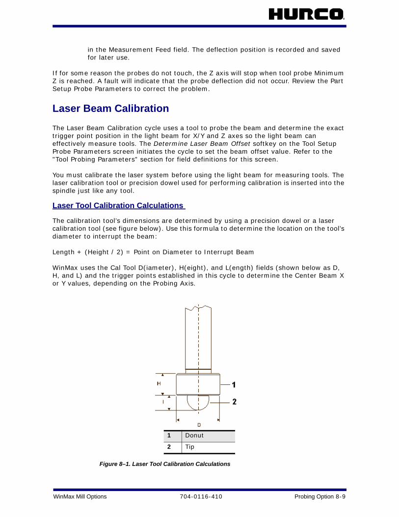
WinMax Mill Options 704-0116-410 Probing Option 8-9
in the Measurement Feed field. The deflection position is recorded and saved for later use.
If for some reason the probes do not touch, the Z axis will stop when tool probe Minimum Z is reached. A fault will indicate that the probe deflection did not occur. Review the Part Setup Probe Parameters to correct the problem.
Laser Beam Calibration
The Laser Beam Calibration cycle uses a tool to probe the beam and determine the exact trigger point position in the light beam for X/Y and Z axes so the light beam can effectively measure tools. The Determine Laser Beam Offset softkey on the Tool Setup Probe Parameters screen initiates the cycle to set the beam offset value. Refer to the "Tool Probing Parameters" section for field definitions for this screen.
You must calibrate the laser system before using the light beam for measuring tools. The laser calibration tool or precision dowel used for performing calibration is inserted into the spindle just like any tool.
Laser Tool Calibration Calculations
The calibration tool’s dimensions are determined by using a precision dowel or a laser calibration tool (see figure below). Use this formula to determine the location on the tool’s diameter to interrupt the beam:
Length + (Height / 2) = Point on Diameter to Interrupt Beam
WinMax uses the Cal Tool D(iameter), H(eight), and L(ength) fields (shown below as D, H, and L) and the trigger points established in this cycle to determine the Center Beam X or Y values, depending on the Probing Axis.
Figure 8–1. Laser Tool Calibration Calculations
1 Donut
2 Tip

8 - 10 Probing Option 704-0116-410 WinMax Mill Options
Laser Tool Calibration Cycle
Follow these steps to run the Laser Calibration Tool cycle:
1. Access the Tool Setup Probe Parameters screen using this softkey sequence:
a. Tool Setup softkey. b. Probing softkey. c. Tool Probe Parameters softkey.
2. In the Type field, select Laser Probe.
3. Enter values in the Cal Tool D, H, or L fields. The Determine Laser Beam Offset softkey appears when the cursor is in any of these fields.
4. Select the Determine Laser Beam Offset softkey.
The figure below illustrates the tool motion during this cycle:
Figure 8–2. Laser Tool Calibration Cycle

WinMax Mill Options 704-0116-410 Probing Option 8-11
Tool Probe Deflection Offset Calibration
Tool and part probe deflection offsets are the difference between the contact point of the probe and the actual receipt of a probe deflection signal. The offsets may vary for each direction of deflection. The switch points are repeatable to one micron or less.
These offsets need to be adjusted during an initial probe installation, a new stylus installation, or for centering or re-centering a stylus. They do not need to be performed each time the control is reset.
Tool Probe Deflection Offset
To access the Tool Probe Deflection Offset screen:
1. Select the Input console button to access the Input screen.
2. Select the Tool Setup softkey.
3. Select the Probing softkey
4. Select the Tool Probe Setup Parameters softkey.
5. Select the Tool Probe Deflection Offset softkey.
The Reference Tool Diameter field holds the diameter of the tool being probed.
The probe orientation determines the offsets used in the Probe Stylus Position fields. The -Z offset is always used along with +/-X or +/-Y, depending from which direction the probe can deflect.
The following sections describe the two methods for determining Tool Probe Deflection Offsets: Absolute Location or Reference Tool Touch.
Absolute Location
Use an edge finder to determine the absolute location of each edge of the probe stylus. Follow these steps:
1. Enter the Reference Tool Diameter.
2. Position the cursor on the desired offset field.
3. Position the reference tool to the correct start position.
4. Press the Use Probe to Determine Offset softkey. The Start Button flashes.
5. Press the flashing Start Button.
a. The cursor position determines which axis is moved and in what direction. b. The deflected position is used to calculate the offsets. c. The offset value appears in the current field. d. The offsets are saved by the system so they are retained after power to the
machine is turned off. e. Unused fields contain a 0 value. f. The sign of the offset is + for plus axis deflections and - for negative axis
deflections.
Reference Tool Touch

8 - 12 Probing Option 704-0116-410 WinMax Mill Options
Use a feeler gauge to determine the position where the reference tool touches the top and each side of the probe stylus. Follow the prompts on the screen to know which side of the stylus to use. Follow these steps:
1. Enter a 0 for the Reference Tool Diameter.
2. Position the reference tool in the correct start position. Begin with the top of the stylus.
3. Place the cursor in the -Z field of the Probe Stylus column.
4. Press the Use Probe to Determine Offset softkey. The Start Button flashes.
5. Press the flashing Start Button.
a. The cursor position determines which axis is moved and in what direction. b. The deflected position is used to calculate the offsets. c. The offset value appears in the -Z field. d. The offsets are saved by the system so they are retained after power to
the machine is turned off. e. Unused fields contain a 0 value. f. The sign of the offset is + for plus axis deflections and - for negative axis
deflections.
6. Repeat these steps for the other two axis positions (+/- X and +/-Y). Position the reference tool appropriately and put the cursor in the appropriate Probe Stylus field.
You can manually adjust the deflection offsets to optimize performance. By running a probe cycle on a reference too, you can make slight adjustments to the deflection offsets until the cycle returns with the exact value(s) desired.
Part Probe Calibration
This section describes the probe calibration and cycles available with the Probing Option. Once the probing equipment is calibrated, the tool and part can be calibrated using the probing equipment. This information can be stored in Tool or Part Setup, or in a data block, to be executed with the part program.
Probe calibration is only required on machines that also have a tool probe installed. Calibration methods vary between systems with tool probing only, and those with both tool and part probing. See the "Tool Probe Calibration and Cycles" section for more information.

WinMax Mill Options 704-0116-410 Probing Option 8-13
Part Probe Deflection Offset Calibration
Part probe deflection offset is the difference between the contact point of the probe and the actual receipt of a probe deflection signal. The offset may vary for each direction of deflection.
Part probe deflection offsets need to be adjusted during an initial probe installation, a new stylus installation, or for centering or re-centering a stylus.
Part Probe Deflection Offset
To access Part Probe Deflection Offset:
1. Select the Input console key to access the Input screen.
2. Press the Part Setup softkey.
3. Press the Probing softkey. The Part Setup screen is displayed with the Part Probing menu.
4. Select the Part Probe Deflection Offsets softkey. The screen has softkeys for selecting the method to use for determining offsets.
The following sections describe the procedures to follow the Ring Gauge Method and Reference Block Method.
Ring Gauge
The Ring Gauge method probes in a circular pattern. Select the Part Probe Deflection Offsets softkey, followed by the Ring Gauge softkey. The following screen appears:
Follow these steps to determine a Ring Gauge Deflection Offset:
1. Enter the Diameter of the part.
2. Use an indicator or some similar method to determine the center of the gauge. Enter the Center of the gauge in the Center X and Center Y fields.
3. Jog the spindle to a point where the probe just touches the part. Enter that location in the Datum Z field by typing it in or by pressing the Store Position key on the Jog control.
4. Position the probe tip inside the gauge at the desired depth and select the Use Gauge to Get X&Y Offsets softkey. The Start button begins to flash.
5. Press the Start button to begin the cycle.
6. The probe touches the part at 36 points (10 increments) inside the gauge to automatically calculate the X and Y offsets. To determine the Z offset, position the probe tip above the chosen datum point and select the Use Datum Point to Get Z Offset softkey. The Start Button begins to flash.
7. Press the Start button to begin the cycle.
8. The probe touches off the datum point and calculates the offset.
9. The Offset values appear on the screen and are stored in memory. This offset will be used anytime the control uses a probe location.
Offset values may be entered manually. If you know the readings are off by a certain

8 - 14 Probing Option 704-0116-410 WinMax Mill Options
amount, you can make adjustments without even using the probe. The sign of the offset should be + for plus axis deflections, and - for minus axis deflections.
Reference Block
The Reference Block method probes in the + or - X or Y direction. Select the Part Probe Deflection Offsets softkey, followed by the Reference Block Method softkey. The following screen appears:
Follow these steps to determine the Reference Block Deflection Offsets for the X or Y axes:
1. Enter X or Y values manually in the Reference Block X or Y fields.
2. Position the cursor under the Deflection Offset column at the offset to be determined.
3. Jog the machine so the part probe is in the proper location to touch off the reference block for the desired axis and direction.
4. Press the Use Probe to Determine Offset softkey, and the Start button begins to flash.
5. Press the Start Button to start the cycle The probe touches off the reference block. The offset values are calculated, appear on the screen, and are stored in memory.
Follow these steps to determine the offset for the Z axis:
1. Jog the probe to the top of the reference block.
2. Use a feeler gauge to determine where the tip of the stylus would touch the reference block. Enter this value in the -Z field in the Reference Block column.
3. Select the Use Probe to Determine Offset softkey. The probe touches off the part in the Z axis to determine the offset.
Offset values may be entered manually. If you know the readings are off by a certain amount, you can make adjustments without using the probe.
The sign of the offset should be + for plus axis deflections and - for minus axis deflections.
• The probe measures the part at 36 points in 10° increments on the ring gauge.
• The 4 points measured on the reference block correspond to the 0°, 90°, 180°, and 270° values on the ring gauge. The remaining 32 values are estimated using the 4 actual measurements to fill in the 10° incremental offsets.
The Ring Gauge method is more accurate than the Reference Block method.

WinMax Mill Options 704-0116-410 Probing Option 8-15
Tool Setup Probing SoftkeysTool Setup Probing softkeys are as follows:
• Tool Probe Setup Parameters—Select the tool probe type and access tool probe parameters. Tool probe types are: Touch Probe, Laser Probe and No Probe. Refer to Tool Probe Setup Parameters, on page 8 - 2.
• Calibrate the Tool Probe—Determine the Z location of the tool probe. Calibrate the Tool Probe only once for each reset of the control. See Tool Probe Calibration, on page 8 - 6.
• Probe A Single Tool—Determines the length and/or diameter of a single tool.
• Probe Multiple Tools—Determines the length and/or diameter of multiple tools.
• Position Tool Over the Probe—Position the tool over the probe, before jogging Z to the desired position.
• Select Tool Probe Cycle—Determine what part of the tool will be probed:
• None – no tool probing occurs
• Length – determine tool length
• Diameter – determine tool diameter
• Length & Diameter - determine tool length and diameter.
• Probe Current Tool Now—Available when the tool on the Tool Setup screen is also the tool in spindle. If the tool is already in the proper position for probing, the Z axis will not retract. Use this feature when the tool is just above the probe and the Rapid Z position is set. After probing, the Tool Setup screen reappears, and a "P" indicates the probed fields.
• Exit—Return to the Tool Setup screen.

8 - 16 Probing Option 704-0116-410 WinMax Mill Options
Tool Setup Probing FieldsTool Setup Probing fields are as follows:
• Rapid Z Position—The tool probe (in the Z axis) rapids down to this position and then continues downward at the speed specified in the Fast Feed field. Use the remote jog unit or type in a value for the Rapid Z Position field.
With the cursor in this field, the Position Tool Over Probe softkey can be used.
• Spindle Usage—Specifies in which direction the spindle should operate during the probe cycle. Choices are: manual (free rotating), oriented, clockwise (CW) or counter clockwise (CCW).
The default value for a touch tool probe is the reverse of the programmed tool. For example, if the tool is CW, Spindle Usage for a touch tool probe will default to CCW. For a laser tool probe, Spindle Usage value defaults to the programmed tool direction.
• Spindle RPM—Specifies spindle speed when the Spindle Usage field is set to either CW or CCW. When the operator updates the diameter setting for the tool probe, the Spindle RPM field will be updated with a suggested value – this value may be overwritten by the operator.
• Fast Feed—Specifies the feed rate used when making the initial touch of the probe (prior to measurement touches). When the operator updates the diameter setting for the tool probe, the Fast Feed field will be updated with a suggested value – this value may be overwritten by the operator.
• Slow Feed—Specifies the feed rate used when taking measurements after the initial deflection. The default value is 4 mm per minute for a touch probe, 25.4 mm per minute for a laser probe.
• Minimum Z—The lowest position that the Z axis will travel to during the probe cycle. Sets up a safety zone for each tool. The Minimum Z value should be low enough to allow proper deflection of the probe - especially important when checking diameter since the tool must drop down next to the probe stylus.
• Length Offset X, Y—Used to change the X or Y table position when probing tool length. This field will be ignored when probing tool diameter. Required for tools that have a cutter offset from the center.
• Z Drop Down Depth—Used only when measuring tool diameter. This parameter (a negative value) indicates the distance to drop down from where the tip of the tool touches the top of the probe. For example, if you want to measure the diameter of the tool ¼" from the tip, this parameter would be set to –0.25".
• Side Clearance—Specifies an additional distance to leave between the tool and tool probe when determining the tool diameter. This value can be adjusted to optimize probe cycle time.
• Multi-Tool Probing—Specifies which tools to probe and which to skip - used only in the multiple tool calibration cycle.
• Sister Tool—Identifies a spare tool to be used with Tool Monitoring.

WinMax Mill Options 704-0116-410 Probing Option 8-17
Probe Part SetupUse the Probe Part Setup data block to perform a part setup function using a probe. The probe will locate a point on the part such as a corner. When the program executes this data block, it will automatically probe the part and update Part Zero X, Part Zero Y, Probe Z, and X/Y Skew. The data block may be placed anywhere in the part program except within a Pattern.
The Probe Part Setup fields are defined as follows:
• Block - identifies the block number for this operation. The system determines the number by the position of this data block in the program. This field appears on both the Probe Part Setup and Part Inspection screens.
• Tool - identifies the tool number for this data block and enters that tool's diameter and type on this screen. This field appears on both the Probe Part Setup and Part Inspection screens.
• Part Zero Cycle - use the drop-down list or softkeys that appear when the field is selected to determine the geometric feature for this Part Zero Cycle.
• Preset X/Y - determines the X or Y coordinate to be assigned to the probed location.
• Probe Direction X/Y - (available only for Corner or Intersect) defines the X or Y value that determines the direction (positive or negative) that the probe moves when searching for the part. This field appears on both the Probe Part Setup and Part Inspection screens.
• Probing Radius - (available only for Hole and Cylinder) enter the radius of the geometry. For a cylinder, this defines a clearance range to move the probe outside the cylinder. For a hole, this defines the maximum travel. This field appears on both the Probe Part Setup and Part Inspection screens.
• Z Depth - (available only for Cylinder and Rect. Solid) defines the distance, relative to the Start Position, that the Z axis moves downward before changing direction and searching horizontally for each contact point on the geometry’s surface. This field appears on both the Probe Part Setup and Part Inspection screens.
• Start Angle 1/2/3 - (available only for Hole and Cylinder) defines the three probe deflection points. Relative to the 3:00 position and increasing counterclockwise as viewed from above the part, the default angles are 0, 120, and 240, respectively. Change the angles if the part contains geometry that interferes with the defaults. This field appears on both the Probe Part Setup and Part Inspection screens.
• Probing Length X/Y - (available only for Rect. Pocket and Rect. Solid) identifies the X or Y length of the geometry. For Rect. Pocket, this defines maximum travel. For Rect. Solid, this defines a clearance area to move the probe outside of the solid. This field appears on both the Probe Part Setup and Part Inspection screens.
• Offset X/Y - (available only for Intersect) defines the X or Y offset positions from the Start Location. This field appears on both the Probe Part Setup and Part Inspection screens.

8 - 18 Probing Option 704-0116-410 WinMax Mill Options
• X Start X/Y/Z - defines the X, Y, or Z coordinate that determines the starting point when probing along the X axis. This field appears on both the Probe Part Setup and Part Inspection screens.
• Y Start X/Y/Z - defines the X, Y, or Z coordinate that determines the starting point when probing along the Y axis. This field appears on both the Probe Part Setup and Part Inspection screens.
• XY Start X/Y/Z - ( available only for Hole, Cylinder, Rect. Pocket, and Rect. Solid) defines the X, Y, or Z coordinate that determines the starting point when probing along the XY axis. This field appears on both the Probe Part Setup and Part Inspection screens.
• Z Start X/Y/Z - defines the X, Y, or Z coordinate that determines the starting point when probing along the Z axis.
• Skew Cycle - select the geometric feature for this Skew Cycle from the drop down list or use the softkeys that appear when the Skew Cycle field is selected. If no Skew Cycle, select none.
The following fields appear based on the Geometric figure selected in the Skew Cycle field. They will not appear if None is selected in the Skew Cycle field.
• Skew Axis - defines the axis that is not square to the machine axis. This axis will be probed at two locations to determine its vector.
• Preset X/Y - defines an offset from Part Zero X or Part Zero Y of the feature to be probed.
• Z Depth - (available only when Cylinder or Rect. Solid is selected in the Skew Cycle field) defines the distance, relative to the Start Position, that the Z axis moves downward before changing directions and searching horizontally for each contact point on the geometry’s surface.
• Probing Length X/Y - (available only when Rect. Pocket or Rect. Solid is selected in the Skew Cycle field) identifies the X or Y length of the geometry. For Rect. Pocket, this defines maximum travel. For Rect. Solid, this defines a clearance area to move the probe outside of the solid.
• Probing Radius - (available only when Hole or Cylinder is selected in the Skew Cycle field) enter the radius of the geometry. For a cylinder, this defines a clearance range to move the probe outside the cylinder. For a hole, this defines the maximum travel.
• Probe Direction X/Y - (available only when Edge is selected in the Skew Cycle field) defines the X or Y value that determines the direction (positive or negative) that the probe moves when searching for the part.
• Skew Start X/Y/Z - defines the X, Y, or Z coordinate that determines the starting point for the skewed axis.

WinMax Mill Options 704-0116-410 Probing Option 8-19
Conversational Part Probing Cycles Conversational part probing is used for locating the part’s position and alignment on the table. Inserting a Probe Part Setup data block to run from the part program allows you to probe multiple parts and locate them at run time. This section describes probing cycles which are used for creating Probe Part Setup data blocks.
There are two types of cycles available for probing different types of part features: Probing Cycles, on page 8 - 33 and Part Skew Probing Cycles, on page 8 - 34. The cycles provide a method to automatically enter the Part Zero X, Part Zero Y, Probe Z, and X/Y Skew (deg) fields.
Part Setup Screen
In addition to the standard Part Setup fields defined in Part Setup, WinMax updates these Part Setup fields with data obtained during the probing cycles:
• Part Zero X, Y—the part zero values established during Part Setup. Refer to the "Part Zero Storage" section in this chapter for details about the Part Zero X and Y fields.
• Probe Z—the distance from Z zero to the top of the part (i.e., the height, or Z Plane), including the reference tool or part probe in the spindle.
• Z zero is the Z calibration point of the Z axis (Z = 0.0000).
• WinMax adjusts tool length values automatically and Tool Zero Calibration is recalculated anytime Probe Z is changed.
• X/Y Skew (deg.)—represents, in degrees, how far the part is from perfect alignment with the table. Refer to the “Part Skew Probing Cycles” section of this chapter for more information about X/Y skew.
Part probing can be run either from Manual Mode or from Auto Mode, inside the part program.
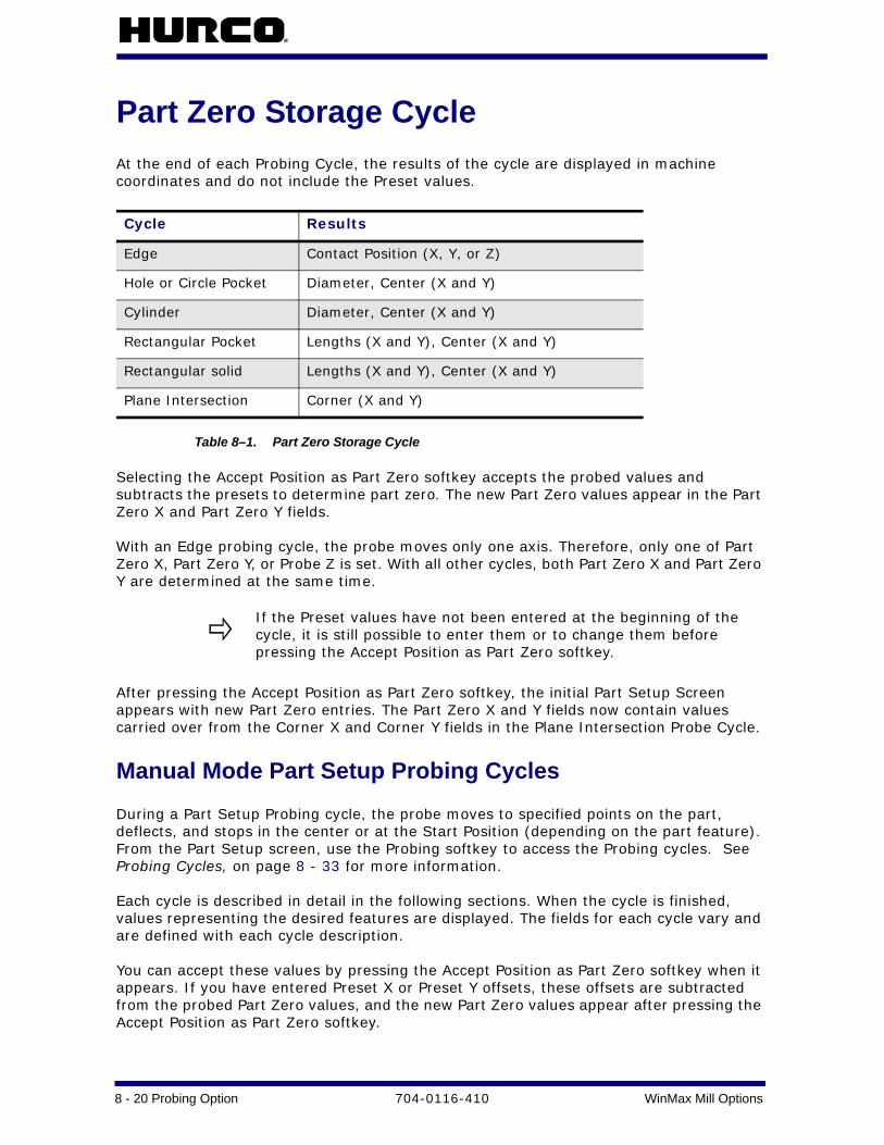
8 - 20 Probing Option 704-0116-410 WinMax Mill Options
Part Zero Storage CycleAt the end of each Probing Cycle, the results of the cycle are displayed in machine coordinates and do not include the Preset values.
Table 8–1. Part Zero Storage Cycle
Selecting the Accept Position as Part Zero softkey accepts the probed values and subtracts the presets to determine part zero. The new Part Zero values appear in the Part Zero X and Part Zero Y fields.
With an Edge probing cycle, the probe moves only one axis. Therefore, only one of Part Zero X, Part Zero Y, or Probe Z is set. With all other cycles, both Part Zero X and Part Zero Y are determined at the same time.
After pressing the Accept Position as Part Zero softkey, the initial Part Setup Screen appears with new Part Zero entries. The Part Zero X and Y fields now contain values carried over from the Corner X and Corner Y fields in the Plane Intersection Probe Cycle.
Manual Mode Part Setup Probing Cycles
During a Part Setup Probing cycle, the probe moves to specified points on the part, deflects, and stops in the center or at the Start Position (depending on the part feature). From the Part Setup screen, use the Probing softkey to access the Probing cycles. See Probing Cycles, on page 8 - 33 for more information.
Each cycle is described in detail in the following sections. When the cycle is finished, values representing the desired features are displayed. The fields for each cycle vary and are defined with each cycle description.
You can accept these values by pressing the Accept Position as Part Zero softkey when it appears. If you have entered Preset X or Preset Y offsets, these offsets are subtracted from the probed Part Zero values, and the new Part Zero values appear after pressing the Accept Position as Part Zero softkey.
Cycle Results
Edge Contact Position (X, Y, or Z)
Hole or Circle Pocket Diameter, Center (X and Y)
Cylinder Diameter, Center (X and Y)
Rectangular Pocket Lengths (X and Y), Center (X and Y)
Rectangular solid Lengths (X and Y), Center (X and Y)
Plane Intersection Corner (X and Y)
If the Preset values have not been entered at the beginning of the cycle, it is still possible to enter them or to change them before pressing the Accept Position as Part Zero softkey.

WinMax Mill Options 704-0116-410 Probing Option 8-21
Follow these steps to access the Part Probe Cycles:
1. From the Part Setup screen, select the Probing softkey. These softkeys appear for selecting Probing functions:
2. Select the Part Zero Probe Cycles softkey. These softkeys appear for selecting the Part Probe Cycle types:
Depending on the Probing Cycle selected, different probing fields appear on the Part Setup screen.
Manual Mode Part Skew Probing Cycles
From the Part Setup screen, use the Probing softkey to access the Probing cycles. (See Probing Cycles, on page 8 - 33.) During a Part Skew Probing cycle the probe moves to specified points on the part, deflects, and stops in the center of the part feature. These cycles detect and compensate for X/Y skew in the work piece. X/Y skew represents, in degrees, how far the part is from perfect alignment with the table.
• A positive skew angle means the part is rotated in a counterclockwise direction from the machine axes (as viewed from above the part).
• A negative skew angle indicates a clockwise rotation from the machine axes.
Although this angle, if known, can be typed in, it is easier and more accurate to let the probe find the skew angle and automatically enter it.
After probing the Part Zero position as a reference, the skew cycles allow you to probe a second feature on the part and adjust all machining operations by the skew angle to exactly match the part.
When the cycle is finished, the software displays values representing the desired features. The fields for each cycle vary and are defined with each cycle description.
You can accept these values by pressing the Accept X/Y Skew Angle softkey when it appears. Preset X or Preset Y offsets are used in the skew calculation. The presets are subtracted from the probed Part Zero values, and the new Part Zero values appear after pressing the Accept Position as Part Zero softkey.
For best results, it is recommended that you use the probe for determining Part Zero X, Part Zero Y, and X/Y Skew. Entering values for any of these fields with the keypad reduces the amount of information available for skew calculations. Also, the software must make assumptions that may reduce accuracy.

8 - 22 Probing Option 704-0116-410 WinMax Mill Options
The figure below illustrates a skewed work piece with a Preset Y offset.
Figure 8–3. Skewed work piece with Preset Y offset
Skew Compensation is intended to be used for correcting a slight misalignment. If the skew angle contains only one Preset value and is greater than approximately 3 degrees, then Part Skew probing may not be exact, especially for Edge and Rectangular cycles.
Follow these steps to perform a Skew Probe Cycle for work piece skew compensation:
1. Perform the Part Zero Probe Cycle. Refer to the appropriate Part Probe Cycle in this chapter (i.e., Edge, Cylinder, etc.) or more information.
2. From the Part Setup screen, select the Probing softkey followed by the Part Skew Probe Cycles softkey to access the Part Skew Probe Cycles:
3. The following screen will appear for selecting the Skew Probe Cycle type. Press the appropriate softkey to select the desired cycle.
Depending on the Skew Probing Cycle selected, different probing fields appear on the Part Setup screen.
Enter offsets for Preset X and Preset Y for a precise Skew Angle. If only one Preset value is entered, the skew angle will be approximate and should not exceed 3 degrees.
The following sections describe how to program each of the Part Skew Probing Cycles.
WinMax Mill Options 704-0116-410 Probing Option 8-23
Automatic Mode
To locate part zero and to determine skew in the X-Y plane as part of the program instead of manually during Part Setup, the Probe Part Setup conversational data block can be used to automatically perform this function.
Access the Probe Part Setup data block from the Part Programming screen as a Miscellaneous Data Block. Select the Miscellaneous softkey from the New Block screen.
Probe Part Setup Data Block From the New Block screen, press the Probe Part Setup softkey. The Probe Part Setup data block screen appears with fields for programming cycles to determine part zero alone or in addition to determining the skew in the XY plane.
The fields on the left-hand side of the screen and the X, Y, and Z Start fields apply to the Part Zero Cycle; the fields on the right-hand side of the screen and the Skew Start fields apply to the Skew Cycle.
Probe Part Setup Fields
The Probe Part Setup screen contains fields for the Part Zero Cycle and the Skew Cycle. The fields change depending on the selected cycle.

8 - 24 Probing Option 704-0116-410 WinMax Mill Options
Automatic Part Zero Cycles
The fields listed below apply to Part Zero Cycles indicated and are defined as follows:
Table 8–2. Automatic Part Zero Cycles
Part Zero Cycle Field Definition All cycles Tool the tool number of the part probe.
All cycles Part Zero Cycle the geometric feature for this Part Zero cycle. Softkey choices appear for selecting the appropriate feature when the cursor is in this field.
All cycles Preset X Preset Y
an offset for Part Zero X and/or Part Zero Y from the probed feature.
Plane Intersection (Non-Rectangular Corner) Cycle, on page 8 - 46
Probe Direction X Probe Direction Y
based on the Probe Axis field, defines which direction, positive or negative, the probe moves when looking for the part.
Rectangular Pocket Skew Cycle, on page 8 - 51 and
Rectangular Solid Skew Cycle, on page 8 - 52
Probing Length X Probing Length Y
the X or Y length of the geometry.
For Pocket this defines maximum travel.
For Solid this defines a clearance area to move the probe outside the Solid.
Cylinder Cycle, on page 8 - 40 and
Hole or Circle Pocket Cycle, on page 8 - 38
Probing Radius the radius of the geometry.
For Cylinder this defines a clearance range to move the probe outside the Cylinder.
For Hole or Circle this defines maximum travel.
Cylinder Cycle, on page 8 - 40 and
Rectangular Solid Outside Cycle, on page 8 - 44
Z Depth distance the Z axis moves downward before changing direction and searching horizontally for each contact point on the geometry’s surface. Z Depth can be set to move the probe anywhere within the Z Axis travel limits.
Plane Intersection (Non-Rectangular Corner) Cycle, on page 8 - 46
Offset X Offset Y
X or Y offset positions from the Start location.
Cylinder Cycle, on page 8 - 40 and
Hole or Circle Pocket Cycle, on page 8 - 38
Start Angle1 Start Angle2 Start Angle3
the three probe deflection points. Relative to the 3:00 position and increasing counter-clockwise as viewed from above the part, the default angles are 0, 120, and 240, respectively. Change the angles if the part contains geometry that interferes with the defaults.
All cycles X, Y, Z Start Positions
where to begin the probing process. The easiest method for entering the start positions is to jog the probe down to the desired start location and press the Store Position key. A single push of this key automatically enters all three coordinates (X, Y, and Z) for one Start position.

WinMax Mill Options 704-0116-410 Probing Option 8-25
Automatic Skew Cycles
These fields apply to the Skew Cycle indicated and are defined as follows:
Table 8–3. Automatic Skew Cycles
Skew Cycle Field Definition All cycles Tool the tool number of the part probe.
All Skew cycles Skew Cycle the geometric feature for this Part Skew cycle. Softkey choices appear for selecting the appropriate feature when the cursor is in this field.
All Skew cycles Skew Axis define either the X or Y axis as the skew axis. There is no skewing in Z.
All Skew cycles Preset X or Preset Y
an offset from Part Zero X or Part Zero Y of the feature to be probed. NOTE: Preset X and Preset Y are available in all cases. For better and more accurate skew compensation, the user should enter values for both fields
Cylinder Skew Cycle, on page 8 - 50
and
Rectangular Solid Skew Cycle, on page 8 - 52
Z Depth distance the Z axis moves downward before changing direction and searching horizontally for each contact point on the geometry’s surface. Z Depth can be set to move the probe anywhere within the Z Axis travel limits.
Rectangular Pocket Skew Cycle, on page 8 - 51
and
Rectangular Solid Skew Cycle, on page 8 - 52
Probing Length X Probing Length Y
the X or Y length of the geometry.
For Pocket this defines maximum travel.
For Solid this defines a clearance area to move the probe outside the Solid.
Cylinder Skew Cycle, on page 8 - 50
and
Hole or Circle Pocket Skew Cycle, on page 8 - 49
Probing Radius the radius of the geometry.
For Cylinder this defines a clearance range to move the probe outside the Cylinder.
For Hole or Circle this defines maximum travel.
Edge Skew Cycle, on page 8 - 48
Probe Direction X or Y (depending on Skew Axis selection)
direction, positive or negative, the probe moves when looking for the part.
All Skew cycles Skew Start Positions where to begin the probing process. The easiest method for entering the start positions is to jog the probe down to the desired start location and press the Store Position key. A single push of this key automatically enters all three coordinates (X, Y, and Z) for one Start position.

8 - 26 Probing Option 704-0116-410 WinMax Mill Options
Probe Part Setup Data Block Execution When the program executes this data block, it will automatically probe the part and update Part Zero X, Part Zero Y, Probe Z and X/Y Skew. The data block may be placed anywhere in the part program except within a Pattern.
Part Inspection Cycles
To access the Part Inspection cycles, follow this softkey sequence from the Input screen:
1. Select Part Programming.
2. Select Miscellaneous.
3. Select More.
4. Select the Part Inspection softkey.
Part Inspection Fields
The fields on the Part Inspection screen change depending on the selected cycle and are defined as follows:
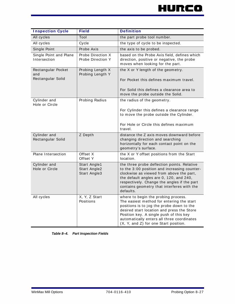
WinMax Mill Options 704-0116-410 Probing Option 8-27
Table 8–4. Part Inspection Fields
Inspection Cycle Field Definition
All cycles Tool the part probe tool number.
All cycles Cycle the type of cycle to be inspected.
Single Point Probe Axis the axis to be probed.
Single Point and Plane Intersection
Probe Direction X Probe Direction Y
based on the Probe Axis field, defines which direction, positive or negative, the probe moves when looking for the part.
Rectangular Pocket and Rectangular Solid
Probing Length X Probing Length Y
the X or Y length of the geometry.
For Pocket this defines maximum travel.
For Solid this defines a clearance area to move the probe outside the Solid.
Cylinder and Hole or Circle
Probing Radius the radius of the geometry.
For Cylinder this defines a clearance range to move the probe outside the Cylinder.
For Hole or Circle this defines maximum travel.
Cylinder and Rectangular Solid
Z Depth distance the Z axis moves downward before changing direction and searching horizontally for each contact point on the geometry’s surface.
Plane Intersection Offset X Offset Y
the X or Y offset positions from the Start location.
Cylinder and Hole or Circle
Start Angle1 Start Angle2 Start Angle3
the three probe deflection points. Relative to the 3:00 position and increasing counter-clockwise as viewed from above the part, the default angles are 0, 120, and 240, respectively. Change the angles if the part contains geometry that interferes with the defaults.
All cycles X, Y, Z Start Positions
where to begin the probing process. The easiest method for entering the start positions is to jog the probe down to the desired start location and press the Store Position key. A single push of this key automatically enters all three coordinates (X, Y, and Z) for one Start position.

8 - 28 Probing Option 704-0116-410 WinMax Mill Options
Part Inspection Programming
Follow these steps to program a Part Inspection data block:
1. Enter the part probe tool number in the tool field.
2. When the cursor is on the Inspection Cycle field, the softkeys change. Select a cycle type for the Inspection Cycle field.
3. Program the remaining fields as described in the "Part Inspection Fields" section. The data block is stored with the program and executed automatically.
Part Inspection Files
When the Part Inspection data block is executed, the part inspection files are automatically created. The position data is presented in part relative coordinates.
Part Inspection files are saved to the same location as the part program, and have the same name as the part program, with a .TXT filename extension. These files can be printed with the Probing Data Printing softkey in Utilities/Printing Setup.
Probe Tool Monitoring
Probe Tool Monitoring is available to automatically monitor calibrated tools and detect breakage or wear.
The software compares the current tool dimensions to the calibrated dimensions stored in Tool Setup for the programmed tool. If the current dimensions deviate from the defined tolerance programmed in the tool monitoring menus, the tool is defective.
It is possible to program a spare tool to automatically replace a defective monitored tool. If the spare tool is not programmed, or if there is no ATC, axis motion stops and the following message appears on the screen: “Tool # x is defective, no more tools to substitute.”
You can invoke tool monitoring in two ways:
• Enable the Program Parameters Automatic Tool Monitoring field. This setup automatically invokes tool monitoring immediately after tool changes for every probed tool.
• Use a data block in a Conversational Part Program to define which tool should be monitored through a specific monitoring cycle.
For single point inspection, the reported Z part position includes the Offset Z value from Part Setup.

WinMax Mill Options 704-0116-410 Probing Option 8-29
The following fields appear on the Tool Monitoring screen:
• Block - identifies the block number for this operation. The system determines the number by the position of this data block in the program. To move to another block, enter the number of the block.
• Probe Cycle Type - displays the type of detection cycle selected for the Probe Tool Monitoring. You may select Tool Breakage Detection, Tool Length Wear Detection, Tool Diameter Wear Detection, or Tool Length & Diameter Wear Detection. The selection in this field determines the fields that appear on the Tool Monitoring screen.
• Tool - displays the number of the tool to be monitored. Enter the number of the tool that you wish to be monitored in this block.
• Breakage Tolerance - (available only for Tool Breakage Probe Cycle Types) enter the amount of deviation from the tool length programmed in the Zero Calibration field on the Tool Setup screen.
• Zero Cal Tolerance - (available only for Tool Length Wear Detection and Tool Length & Diameter Wear Detection Probe Cycle Types) enter the amount of deviation from the tool length programmed in the Zero Calibration field on the Tool Setup screen.
• Diameter Tolerance - (available only for Tool Diameter Wear Detection and Tool Length & Diameter Wear Detection Probe Cycle Types) enter the amount of deviation from the tool diameter programmed in the Diameter field on the Tool Setup screen.
• Speed - displays the spindle speed value defined for this tool on the Tool Setup Screen. This value can be manually changed on the Tool Monitoring screen. This field does not appear if the Spindle Usage field in Tool Setup Probing is set to Manual or Oriented.
• Direction - select the direction (CW or CCW) that the spindle will run. This field does not appear if the Spindle Usage field in Tool Setup Probing is set to Manual or Oriented.
• Probing Method - displays the method for referencing the tool that was specified in Tool Setup; field is read-only.
• Spindle Usage - displays the direction in which the spindle should operate during the probe cycle; specified in Tool Setup. Choices are manual (free rotating), oriented, clockwise (CW) or counter clockwise (CCW).
• Sister Tool - displays the tool that will be used to automatically replace the monitored tool if it deviates from the limits specified in the BREAKAGE TOLERANCE, ZERO CAL TOLERANCE, or DIAMETER TOLERANCE fields. The field is read-only. Sister tool is specified in Tool Setup.
You may use the above fields to program data blocks that will check for Tool Breakage and/or Tool Wear.

8 - 30 Probing Option 704-0116-410 WinMax Mill Options
Manual Tool Probing Cycles
Tool probing determines the Zero Calibration and/or Diameter values for a particular tool, and stores these values in the Tool Setup screen. The tool’s length will be stored in the Zero Calibration field. The tool’s diameter can also be probed and stored in the Diameter field.
Before using the tool probe, review the changes that appear on the Tool Setup screen. Any tool that has been calibrated with the probe will have a "P" designator next to the Diameter and Zero Calibration values.
The following two softkeys, Probe a Single Tool and Probe Multiple Tools allow for manual probing of tools within tool setup. See Probe a Single Tool, on page 8 - 30 and Probe Multiple Tools, on page 8 - 31 for more information.
Probe a Single Tool
The Probe a Single Tool feature determines the Zero Calibration value and/or tool diameter, based on the selection made for the Probe Cycle field. The tool must be already entered in Tool Setup before probing.
Follow these steps to Probe a Single Tool:
1. Select the Input console button to access the Input screen.
2. Select the Tool Setup softkey. The Tool Setup screen appears.
3. Select the More softkey on the Tool Setup Screen.
4. Select the Tool Probing softkey.
5. Select the Probe a Single Tool softkey.
6. Enter the Tool Number to probe.
7. The Start Cycle button flashes. Press Start to begin the probe cycle.
If the tool diameter will be probed, an approximate value must be entered in the diameter field. This approximate value will be replaced by the Probe value after the tool is probed.
A tool’s Zero Calibration value is automatically recalculated anytime Probe Z is changed. If the Zero Calibration seems to be incorrect, check the Probe Z value in the Part Setup screen.

WinMax Mill Options 704-0116-410 Probing Option 8-31
Probe Multiple Tools
The Probe Multiple Tools feature determines the Zero Calibration value and/or tool diameter, based on the selection made for the Probe Cycle field. The tools must be already entered in Tool Setup before probing.
All tools that have been defined in Tool Setup and have Multi-Tool Probing field set to Yes will be included in the multiple tool probing cycle. Any tool that has Multi-Tool Probing set to No will be skipped, but may still be probed using the single tool cycle.
Follow these steps to perform a Probe Multiple Tools cycle:
1. Select the Input console button to access the Input screen.
2. Select the Tool Setup softkey. The Tool Setup screen appears.
3. Select the More softkey on the Tool Setup Screen.
4. Select the Probe Multiple Tools softkey.
5. The Start Cycle button flashes and you are prompted to press it.
6. Press the Start Cycle button to continue. A tool will be probed only if the Probe Cycle is defined and the Multi-Tool Probing field is set to Yes. The first tool to meet these requirements is placed in the spindle and probed.
7. The next tool to meet the multi tool probing criteria is located in the tool list. A tool change occurs and the tool is probed.
8. The tool change and probing process repeats until the original tool in spindle is reached.
If the diameters will be probed, an approximate value must be entered in the diameter field for each tool. The approximate values will be replaced by Probe values after each tool is probed.
The entire Probe Multiple Tools process is automatic (as long as the tools are in the ATC), and does not require operator supervision.

8 - 32 Probing Option 704-0116-410 WinMax Mill Options
Tool Wear Detection Data BlockFollow these steps to program a Tool Wear Detection data block:
1. From the Probe Tool Monitoring screen, select the Length Wear Detection, Diameter Wear Detection, or Length and Diameter softkey.
2. Enter the tool number to be monitored. The tool must be programmed in Tool Setup, and it must be calibrated.
3. Enter the Zero Calibration Tolerance or the Diameter Tolerance, or both if monitoring both length and diameter.
4. If desired, adjust the Speed (RPM) value.
When the data block executes, the current tool length is measured and compared with the tool length or diameter tolerance (or both, if monitoring both length and diameter). If the tool is shorter than the Zero Calibration value minus the programmed tolerance, the tool is worn. If the tool’s diameter is less than the Diameter minus the programmed tolerance, the tool is worn. The “P” on the Tool Setup screen is replaced with a “D” to indicate the tool is defective.
If a spare tool was programmed, axis motion stops and a tool change automatically occurs. If there is no spare tool programmed in the ATC, axis motion stops and a message appears asking you to change tools.

WinMax Mill Options 704-0116-410 Probing Option 8-33
Probing Cycles WinMax uses information programmed in the Part Setup screen to perform the Probing Cycles in Manual or Automatic mode.
Part Setup Probing Cycles
The table below describes the process for each Part Setup Probing Cycle:
Table 8–5. Part Setup Probing Cycles
Cycle Type Cycle Parameter Input
Automatic Execution
Results Displayed
Optional Storage
Edge Cycle, on page 8 - 35
Axis Probe Direction Positive or Negative Preset X or Y
Approach edge. Retract. Return to Start Position.
Deflection Position X, Y, or Z
Deflection Position X, Y, or Z is Part Zero X, Part Zero Y, or Probe Z.
Hole or Circle Pocket Cycle, on page 8 - 38
Start Angle 1, 2, 3 Preset X Preset Y
Approach 3 Circle Points from inside. Position Probe into Center.
Center X Center Y Diameter
Center is Part Zero X and Part Zero Y.
Cylinder Cycle, on page 8 - 40
Probing Radius Start Angle 1, 2, 3 Z Depth Preset X Preset Y
Approach 3 Cylinder points from outside. Position Probe above cylinder Center.
Center X Center Y Diameter
Center is Part Zero X and Part Zero Y.
Rectangular Pocket Inside Cycle, on page 8 - 42
Preset X Preset Y
Approach the 4 pocket walls from inside. Position Probe into pocket Center.
Center (X) Center (Y) Length (X) Length (Y)
Center is Part Zero X and Part Zero Y.
Rectangular Solid Outside Cycle, on page 8 - 44
Probing Length (X) Probing Length (Y) Z Depth Preset X Preset Y
Approach the 4 Rectangle walls from outside. Position Probe above rectangle Center.
Center (X) Center (Y) Length (X) Length (Y)
Center is Part Zero X and Part Zero Y.
Plane Intersection (Non-Rectangular Corner) Cycle, on page 8 - 46
X Probe Direction Offset 1 Offset 2 Y Probe Direction Offset 1 Offset 2 Preset X Preset Y
Approach 2 points on each of the two planes. Return to Start Position.
Intersection point of the two planes in the X/Y coordinate system
Intersection point is Part Zero X and Part Zero Y.

8 - 34 Probing Option 704-0116-410 WinMax Mill Options
Part Skew Probing Cycles
The following table describes the process of the Skew Probing Cycles:
Table 8–6. Part Skew Probing Cycles
Skew Cycle Type
Cycle Parameter Input
Automatic Execution
Display of the results
Optional storage
Edge Skew Cycle, on page 8 - 48
Axis X, Y, or Z Probe Direction: Positive or Negative Preset X or Preset Y
Approach edge. Retract. Return to Start Position.
Deflection Position X, Y, or Z Skew Angle (deg)
Skew Angle
Hole or Circle Pocket Skew Cycle, on page 8 - 49
Start Angle 1, 2, 3 Preset X Preset Y
Approach 3 Circle Points from inside. Position Probe into Center.
Center X Center Y Diameter Skew Angle (deg)
Skew Angle
Cylinder Skew Cycle, on page 8 - 50
Probing Radius Z Depth Start Angle 1, 2, 3 Preset X Preset Y
Approach 3 Cylinder Points from outside. Position Probe above cylinder Center.
Center X Center Y Diameter Skew Angle (deg)
Skew Angle
Rectangular Pocket Skew Cycle, on page 8 - 51
Preset X Preset Y
Approach the 4 pocket walls from inside. Position Probe into pocket Center.
Center X Center Y Length X Length Y Skew Angle (deg)
Skew Angle
Rectangular Solid Skew Cycle, on page 8 - 52
Probing Length X Probing Length Y Z Depth Preset X Preset Y
Approach the 4 Rectangle walls from outside. Position Probe above rectangle Center.
Center X Center Y Length X Length Y Skew Angle (deg)
Skew Angle

WinMax Mill Options 704-0116-410 Probing Option 8-35
Edge Cycle
An Edge Cycle is used for determining the location of a specified edge of the part. During an Edge Cycle, the part probe moves to the X, Y, or Z edge of the part and records the deflection position.
The figures below show part probe movement during X, Y, and Z Edge Cycles:
Figure 8–4. Edge Cycle probing in +X direction—Top View
Figure 8–5. Edge Cycle probing in +Y direction—Top View
1 Start Position
1 Start Position
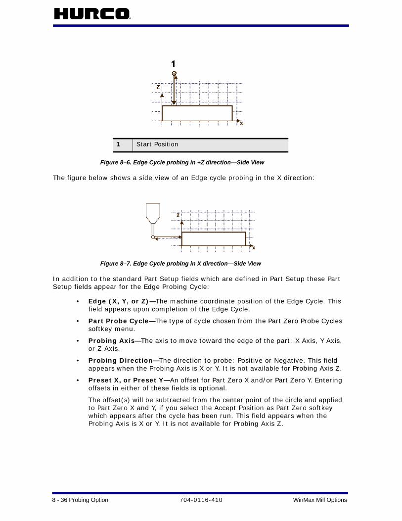
8 - 36 Probing Option 704-0116-410 WinMax Mill Options
Figure 8–6. Edge Cycle probing in +Z direction—Side View
The figure below shows a side view of an Edge cycle probing in the X direction:
Figure 8–7. Edge Cycle probing in X direction—Side View
In addition to the standard Part Setup fields which are defined in Part Setup these Part Setup fields appear for the Edge Probing Cycle:
• Edge (X, Y, or Z)—The machine coordinate position of the Edge Cycle. This field appears upon completion of the Edge Cycle.
• Part Probe Cycle—The type of cycle chosen from the Part Zero Probe Cycles softkey menu.
• Probing Axis—The axis to move toward the edge of the part: X Axis, Y Axis, or Z Axis.
• Probing Direction—The direction to probe: Positive or Negative. This field appears when the Probing Axis is X or Y. It is not available for Probing Axis Z.
• Preset X, or Preset Y—An offset for Part Zero X and/or Part Zero Y. Entering offsets in either of these fields is optional.
The offset(s) will be subtracted from the center point of the circle and applied to Part Zero X and Y, if you select the Accept Position as Part Zero softkey which appears after the cycle has been run. This field appears when the Probing Axis is X or Y. It is not available for Probing Axis Z.
1 Start Position
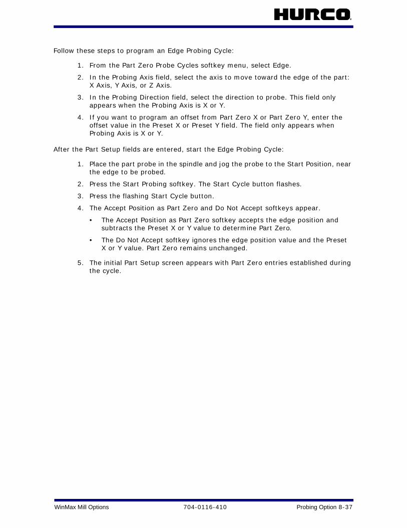
WinMax Mill Options 704-0116-410 Probing Option 8-37
Follow these steps to program an Edge Probing Cycle:
1. From the Part Zero Probe Cycles softkey menu, select Edge.
2. In the Probing Axis field, select the axis to move toward the edge of the part: X Axis, Y Axis, or Z Axis.
3. In the Probing Direction field, select the direction to probe. This field only appears when the Probing Axis is X or Y.
4. If you want to program an offset from Part Zero X or Part Zero Y, enter the offset value in the Preset X or Preset Y field. The field only appears when Probing Axis is X or Y.
After the Part Setup fields are entered, start the Edge Probing Cycle:
1. Place the part probe in the spindle and jog the probe to the Start Position, near the edge to be probed.
2. Press the Start Probing softkey. The Start Cycle button flashes.
3. Press the flashing Start Cycle button.
4. The Accept Position as Part Zero and Do Not Accept softkeys appear.
• The Accept Position as Part Zero softkey accepts the edge position and subtracts the Preset X or Y value to determine Part Zero.
• The Do Not Accept softkey ignores the edge position value and the Preset X or Y value. Part Zero remains unchanged.
5. The initial Part Setup screen appears with Part Zero entries established during the cycle.

8 - 38 Probing Option 704-0116-410 WinMax Mill Options
Hole or Circle Pocket Cycle
The Hole or Pocket Cycle is used for determining the center location and diameter of a hole or pocket. During a Hole or Circle Pocket Cycle, the part probe moves from the inside of the circle out to three points on the edge, touches at each point, and returns to the Start Position within the circle after each touch. The software records each deflection position and calculates the center location. The probe positions in the center of the pocket.
The figure below shows part probe movement during a Hole or Circle Pocket Cycle:
Figure 8–8. Part Probe movement during a Hole or CirclePocket cycle
In addition to the standard Part Setup fields which are defined in Part Setup, these fields appear for the Hole or Circle Pocket Probing Cycle:
• Center X—The Center X machine coordinate location. This field appears upon completion of the cycle.
• Center Y—The Center Y machine coordinate location. This field appears upon completion of the cycle.
• Diameter—The diameter of the hole or circle pocket. This field appears upon completion of the cycle.
• Part Probe Cycle—The type of cycle chosen from the Part Zero Probe Cycles menu.
A Start Position
1 Start Angle 1
2 Start Angle 2
3 Start Angle 3

WinMax Mill Options 704-0116-410 Probing Option 8-39
• Start Angle 1, 2, 3—The three probe deflection points. Relative to the 3:00 position, and increasing counterclockwise as viewed from above the part, the default angles are 0, 120, and 240, respectively. Change the angles if the part contains geometry that interferes with the defaults.
• Preset X and Preset Y—An offset for Part Zero X and/or Part Zero Y. Entering offsets in either of these fields is optional.
The offset(s) will be subtracted from the center point of the circle and applied to Part Zero X and Y if you select the Accept Position as Part Zero softkey, which appears after the cycle has been run.
Follow these steps to program a Hole or Circle Pocket Probing Cycle:
1. From the Part Zero Probe Cycles softkey menu, select Hole or Circle Pocket.
2. In the Start Angle fields, enter the desired approach angles.
3. If you want to program an offset from Part Zero X or Part Zero Y, enter the offset value in the Preset X or Preset Y field.
After Part Setup fields are entered, start the Hole or Circle Pocket Probing Cycle:
1. Place the part probe in the spindle and jog it to the Start Position - into the pocket and below the surface.
2. Press the Start Probing Cycle softkey. The Start Cycle button flashes.
3. Press the Start Cycle button.
4. The Accept Position as Part Zero and Do Not Accept softkeys appear.
• Accept Position as Part Zero accepts the center position and subtracts presets to determine Part Zero.
• Do Not Accept ignores the center value and the Preset X or Y value. Part Zero remains unchanged.
5. The initial Part Setup screen with Part Zero entries appears.

8 - 40 Probing Option 704-0116-410 WinMax Mill Options
Cylinder Cycle
The Cylinder Cycle is used for determining the center location and the diameter of a cylinder. During a Cylinder Cycle, the part probe moves from the Start Position above the cylinder, out and down to three points around the diameter. The probe touches at each point and returns up and over to the Start Position above the cylinder after each touch. The diameter and the center location of the cylinder is determined.
The figure below shows part probe movement during a Cylinder Cycle:
Figure 8–9. Part Probe movement during Cylinder cycle
In addition to the standard Part Setup fields which are defined in Part Setup, these fields appear for the Cylinder Cycle:
• Center X—The Center X machine coordinate location. This field appears upon completion of the cycle.
• Center Y—The Center Y machine coordinate location. This field appears upon completion of the cycle.
• Diameter—The diameter of the cylinder. This field appears upon completion of the cycle.
• Part Probe Cycle—The type of cycle chosen from the Part Zero Probe Cycles softkey menu.
A Start position
1 Start Angle 1
2 Start Angle 2
3 Start Angle 3

WinMax Mill Options 704-0116-410 Probing Option 8-41
• Probing Radius—Value for the probe search radius. This value is used for determining the point at which the probe stops horizontal travel and begins to move downward.
• Start Angle 1, 2, 3—The three probe deflection points. Relative to the 3:00 position and increasing counterclockwise as viewed from above the part, the default angles are 0, 120, and 240, respectively. Change the angles if the part contains geometry that interferes with the defaults.
• Z Depth—Distance the Z axis moves downward before changing direction and searching horizontally for each contact point on the cylinder’s diameter. Z Depth can be set to move the probe anywhere within the Z Axis travel limits.
• Preset X and Preset Y—An offset for Part Zero X and/or Part Zero Y. Entering offsets in either of these fields is optional.
The offset(s) will be subtracted from the center point of the circle and applied to Part Zero X and Y if you select the Accept Position as Part Zero softkey, which appears after the cycle has been run.
Follow these steps to program a Cylinder Probing Cycle:
1. From the Part Zero Probe Cycles softkey menu, select Cylinder.
2. In the Probing Radius field, enter the probe search radius.
3. In the Start Angle fields, enter the desired approach angles.
4. In the Z Depth field, enter the distance the Z axis moves down before changing direction and searching horizontally for each contact point.
5. If you want to program an offset from Part Zero X and Part Zero Y, enter the offset value in the Preset X and Preset Y field.
When the Part Setup fields have been entered, start the Cylinder Probing Cycle:
1. Place the part probe in the spindle and jog the probe to the Start Position, above the cylinder.
2. Press the Start Probing Cycle softkey. The Start Cycle button flashes.
3. Press the flashing Start Cycle button.
4. The Accept Position as Part Zero and Do Not softkeys appear.
• Accept Position as Part Zero - accept the center and subtracts the presets to determine part zero.
• The Do Not Accept - ignore the center values and the Preset X or Y value. Part Zero remains unchanged.
5. The initial Part Setup screen appears with Part Zero entries established during the cycle.
There should be no deflection during the Z move.

8 - 42 Probing Option 704-0116-410 WinMax Mill Options
Rectangular Pocket Inside Cycle
The Rectangular Pocket Inside (or Rectangular Pocket) Cycle is used for determining the center location of the pocket and the X and Y length of the rectangle. During a Rectangular Pocket Cycle, the part probe moves from inside the pocket out to a point on each edge of the rectangle, touches at each point, and returns to the Start Position after each touch. The software records each deflection position and calculates the center location and lengths.
The figure below shows part probe movement during a Rectangular Pocket Cycle.
Figure 8–10. Part Probe movement during Rectangular Pocket cycle
In addition to the standard Part Setup fields which are defined in Part Setup, these fields appear for the Rectangular Pocket Cycle:
• Center X—The Center X machine coordinate location. This field appears upon completion of the cycle.
• Center Y—The Center Y machine coordinate location. This field appears upon completion of the cycle.
• Length (X)—The X length of the pocket. This field appears upon completion of the cycle.
• Length (Y)—The Y length of the pocket. This field appears upon completion of the cycle.
A Start position

WinMax Mill Options 704-0116-410 Probing Option 8-43
• Part Probe Cycle—The type of cycle chosen from the Part Zero Probe Cycles softkey menu.
• Preset X or Preset Y—Offset for Part Zero X and/or Part Zero Y. Entering offsets in either of these fields is optional. The offset(s) will be subtracted from the center point of the pocket and applied to Part Zero X and Y if you select the Accept Position as Part Zero softkey.
Follow these steps to program a Rectangular Pocket Cycle:
1. From the Part Zero Probe Cycles softkey menu, select Rectangular Pocket Inside.
2. If you want to program an offset for Part Zero X or Part Zero Y, enter the offset value in the Preset X or Preset Y field.
After the Part Setup fields are entered, start the Rectangular Pocket Cycle:
1. Place the part probe in the spindle and jog the probe to the Start Position, into the pocket and below the surface.
2. Press the Start Probing Cycle softkey. The Start Cycle button flashes.
3. Press the Start Cycle button.
4. The Accept Position as Part Zero and Do Not Accept softkeys appear. Press the appropriate softkey.
• Accept Position as Part Zero - accept the center and subtracts the presets to determine part zero.
• The Do Not Accept - ignore the center and length values and the Preset X or Y value. Part Zero remains unchanged.
Refer to the "Part Zero Storage" section of this chapter for more information.
5. The initial Part Setup screen appears with Part Zero entries established during the cycle.

8 - 44 Probing Option 704-0116-410 WinMax Mill Options
Rectangular Solid Outside Cycle
A Rectangular Solid Outside (or Rectangular Solid) Cycle is used for determining the center location of the pocket and the X and Y length of the rectangle. During a Rectangular Solid Cycle, the part probe moves from above the rectangle out and down to a point on each of the four walls, touches at each point, and returns to the Start Position after each touch. Each deflection position is recorded the center position and lengths are calculated.
The figure below shows part probe movement during a Rectangular Solid Cycle:
Figure 8–11. Part Probe movement during Rectangular Solid cycle
In addition to the standard Part Setup fields which are defined in Part Setup, these fields appear for the Rectangular Solid Cycle:
• Center X—The Center X machine coordinate location. This field appears upon completion of the cycle.
• Center Y—The Center Y machine coordinate location. This field appears upon completion of the cycle.
• Length (X)—The X length of the rectangle. This field appears upon completion of the cycle.
• Length (Y)—The Y length of the rectangle. This field appears upon completion of the cycle.
• Part Probe Cycle—The type of cycle chosen from the Part Zero Probe Cycles softkey menu.
• Probing Length X—A maximum value of the estimated X length. Half of this value is used to determine the point at which the Z axis begins to move downward (i.e., its horizontal travel limit for X).
A Start position

WinMax Mill Options 704-0116-410 Probing Option 8-45
• Probing Length Y—A maximum value of the estimated Y length. Half of this value is used to determine the point at which the Z axis begins to move downward (i.e., its horizontal travel limit for Y).
• Z Depth—The distance the Z axis moves downward before changing direction and searching horizontally for each contact point on the cylinder’s diameter. Z Depth can be set to move the probe anywhere within the Z Axis travel limits.
• Preset X and Preset Y—An offset for Part Zero X and/or Part Zero Y. Entering offsets in either of these fields is optional. The offset(s) will be subtracted from the center point of the rectangle and applied to Part Zero X and Y if you select the Accept Position as Part Zero softkey, which appears after the cycle has been run.
Follow these steps to program a Rectangular Solid Cycle:
1. From the Part Setup Probe Cycles softkey menu, select Rectangular Solid Outside.
2. In the Probing Length X field, enter an estimate for the X length.
3. In the Probing Length Y field, enter an estimate for the Y length.
4. In the Z Depth field, enter the distance the Z axis should move down.
5. If you want to program an offset for Part Zero X and Part Zero Y, enter the offset value in the Preset X and Preset Y field.
When the Part Setup fields have been entered, start the Rectangular Solid Cycle:
1. Place the part probe in the spindle and jog the probe to the Start Position, above the middle of the rectangle.
2. Press the Start Probing Cycle softkey. The Start Cycle button flashes.
3. Press the Start Cycle button.
4. The Accept Position as Part Zero and Do Not Accept softkeys appear. Press the appropriate softkey.
• Accept Position as Part Zero – accept the center and subtracts the presets to determine part zero.
• The Do Not Accept - ignore the center and length values and the Preset X or Y value. Part Zero remains unchanged.
5. The initial Part Setup screen appears with Part Zero entries established during the cycle.
There should be no deflection during the Z move.

8 - 46 Probing Option 704-0116-410 WinMax Mill Options
Plane Intersection (Non-Rectangular Corner) Cycle
A Plane Intersection Cycle is used for determining an X and Y intersection for a non-rectangular corner. During a Plane Intersection Cycle, the part probe moves from an offset position to two points in the X direction and two points in the Y direction to determine an X and Y intersection point.
The Plane Intersection cycle can be used with solid or pocket geometry. The figure below shows part probe movement with the two types of geometry:
Figure 8–12. Part Probe movement with Solid or Pocket geometry
In addition to the standard Part Setup fields which are defined in Part Setup, these fields appear for the Plane Intersection Cycle:
• Corner X—The X position of the intersection. This field appears when the cycle is finished.
• Corner Y—The Y position of the intersection. This field appears when the cycle is finished.
• Probing Direction X—The X direction to probe: Positive or Negative.
• Offset 1—The first Y offset position.
• Offset 2—The second Y offset position.
• Probing Direction Y—The Y direction to probe: Positive or Negative.
• Offset 1—The first X offset position.
• Offset 2—The second X offset position.
• Preset X and Preset Y—An offset for Part Zero X and/or Part Zero Y. Entering offsets in either of these fields is optional. The offset(s) will be subtracted from the corner point and applied to Part Zero X and Y if you select the Accept Position as Part Zero softkey, which appears after the cycle has run.
A Start Point

WinMax Mill Options 704-0116-410 Probing Option 8-47
Follow these steps to program a Plane Intersection Cycle:
1. From the Part Zero Probe Cycles softkey menu, select Plane Intersection.
2. In the Probing Direction X field, select Positive or Negative.
3. In the Offset 1 field, enter the position for the first Y Offset, relative to the Start Position.
4. In the Offset 2 field, enter the position for the second Y Offset, relative to the Start Position.
5. In the Probing Direction Y field, select Positive or Negative.
6. In the Offset 1 field, enter the position for the first X Offset, relative to the Start Position.
7. In the Offset 2 field, enter the position for the second X Offset, relative to the Start Position.
8. If you want to program an offset from Part Zero X or Part Zero Y, enter the offset value in the Preset X or Preset Y field.
When the Part Setup fields have been entered, start the Plane Intersection Cycle:
1. Place the part probe in the spindle and jog the probe into the Start Position, near the non-rectangular corner.
2. Press the Start Probing Cycle softkey. The Start Cycle button flashes.
3. Press the flashing Start Cycle button.
4. The Accept Position as Part Zero and Do Not Accept softkeys appear. Press the appropriate softkey.
• Accept Position as Part Zero - accept the corner position and subtracts the Preset X or Y value to determine Part Zero.
• The Do Not Accept - ignore the corner values and the Preset X or Y value. Part Zero remains unchanged.
5. The initial Part Setup screen appears with Part Zero entries established during the cycle.

8 - 48 Probing Option 704-0116-410 WinMax Mill Options
Edge Skew Cycle
Follow these steps to program an Edge Skew Probing Cycle:
1. From the Part Setup Skew Probe Cycle softkey menu, select Edge.
2. In the Probing Axis field, select the axis to move toward the edge of the part: X Axis, Y Axis, or Z Axis.
3. In the Probing Direction field, select the direction to probe: Positive or Negative. Z Axis always probes in the Negative direction.
4. Program an offset in the Preset X or Preset Y field, if desired.
When the Part Setup fields have been entered, start the Edge Skew Probing Cycle:
1. Place the part probe in the spindle and jog the probe to the Start Position, near the edge to be probed.
2. Press the Start Probing Cycle softkey. The Start Cycle button flashes.
3. Press the Start Cycle button.
The tool motion for an Edge Skew Cycle is the same as the motion described for an Edge Cycle. The results appear in the Edge (X,Y, or Z) and Skew Angle (Deg) fields. The probe returns to the Start Position.
4. After the cycle runs, the Accept X/Y Skew Angle and Do Not Accept softkeys appear.
• The Accept X/Y Skew Angle softkey accepts the skew position and subtracts the Preset X or Y value to determine Part Zero.
• The Do Not Accept softkey ignores the edge position value and the Preset X or Y value. Part Zero remains unchanged.
5. The initial Part Setup screen appears with the skew value established during the cycle stored in the X/Y Skew (deg) field, if accepted.

WinMax Mill Options 704-0116-410 Probing Option 8-49
Hole or Circle Pocket Skew Cycle
Follow these steps to program a Hole or Circle Pocket Skew Probing Cycle:
1. From the Part Setup Skew Probe Cycle softkey menu, select the Hole or Circle Pocket softkey.
2. In the Start Angle 1, Start Angle 2, and Start Angle 3 fields, enter the desired approach angles.
3. Program an offset in the Preset X and/or Preset Y field(s), if desired.
When the Part Setup fields have been entered, start the Hole or Circle Skew Probing Cycle:
1. Place the part probe in the spindle and jog the probe to the Start Position, inside the pocket near the center.
2. Press the Start Probing Cycle softkey. The Start Cycle button flashes.
3. Press the Start Cycle button. The tool motion for a Hole or Circle Pocket Skew Probing Cycle is the same as the motion described for a Hole or Circle Pocket Cycle. The results appear in the Center X, Center Y, Diameter, and Skew Angle (deg) fields. The probe stops in the center of the pocket.
4. After the cycle runs, the Accept X/Y Skew Angle and Do Not Accept softkeys appear.
• The Accept X/Y Skew Angle softkey accepts the skew position and subtracts the Preset X or Y value to determine Part Zero.
• The Do Not Accept softkey ignores the edge position value and the Preset X or Y value. Part Zero remains unchanged.
Refer to the "Part Zero Storage" section of this chapter for more information.
5. The initial Part Setup screen appears with the skew value established during the cycle stored in the X/Y Skew (deg) field, if accepted.

8 - 50 Probing Option 704-0116-410 WinMax Mill Options
Cylinder Skew Cycle
Follow these steps to program a Cylinder Skew Probing Cycle:
1. From the Part Setup Skew Probe Cycle softkey menu, select Cylinder.
2. In the Probing Radius field, enter the probe search radius.
3. In the Start Angle fields, enter the desired approach angles.
4. In the Z Depth field, enter the distance the Z axis moves down before changing direction and searching horizontally for each contact point.
5. Program an offset in the Preset X and/or Preset Y field(s), if desired.
When the Part Setup fields have been entered, start the Cylinder Skew Probing Cycle:
1. Place the part probe in the spindle and jog the probe to the Start Position, above the cylinder near the center.
2. Press the Start Probing Cycle softkey. The Start Cycle button flashes.
3. Press the Start Cycle button. The tool motion for a Cylinder Skew Probing Cycle is the same as the motion described for a Cylinder Cycle. The results appear in the Center X, Center Y, Diameter, and Skew Angle (deg) fields. The probe stops in the center above the cylinder.
4. After the cycle runs, the Accept X/Y Skew Angle and Do Not Accept softkeys appear.
• The Accept X/Y Skew Angle softkey accepts the skew position and subtracts the Preset X or Y value to determine Part Zero.
• The Do Not Accept softkey ignores the edge position value and the Preset X or Y value. Part Zero remains unchanged.
Refer to the "Part Zero Storage" section of this chapter for more information.
5. The initial Part Setup screen appears with the skew value established during the cycle stored in the X/Y Skew (deg) field, if accepted.

WinMax Mill Options 704-0116-410 Probing Option 8-51
Rectangular Pocket Skew Cycle
Follow these steps to program a Rectangular Pocket Skew Cycle:
1. From the Part Setup Skew Probe Cycle softkey menu, select Rectangular Pocket Inside.
2. Program an offset for the Preset X and/or Preset Y field, if desired.
When the Part Setup fields have been entered, start the Rectangular Pocket Skew Probing Cycle:
1. Place the part probe in the spindle and jog the probe to the Start Position, inside the rectangular pocket.
2. Press the Start Probing Cycle softkey. The Start Cycle button flashes.
3. Press the Start Cycle button.
The tool motion for a Rectangular Pocket Skew Probing Cycle is the same as the motion described for a Rectangular Pocket Cycle. The results are displayed on the screen in the Center X, Center Y, Length (X), Length (Y) and Skew Angle (deg) fields. The probe stops in the center of the pocket.
4. After the cycle runs, the Accept X/Y Skew Angle and Do Not Accept softkeys appear.
• The Accept X/Y Skew Angle softkey accepts the skew position and subtracts the Preset X or Y value to determine Part Zero.
• The Do Not Accept softkey ignores the edge position value and the Preset X or Y value. Part Zero remains unchanged.
Refer to Part Zero Storage Cycle, on page 8 - 20 for more information.
5. The initial Part Setup screen appears with the skew value established during the cycle stored in the X/Y Skew (deg) field, if accepted.

8 - 52 Probing Option 704-0116-410 WinMax Mill Options
Rectangular Solid Skew Cycle
Follow these steps to program a Rectangular Solid Skew Cycle:
1. From the Part Setup Skew Probe Cycle softkey menu, select Rectangular Solid Outside.
2. In the Probing Length X field, enter the pocket’s estimated X Length.
3. In the Probing Length Y field, enter the pocket’s estimated Y Length.
4. In the Z Depth field, enter the distance the Z axis moves downward before changing direction and moving to the edges for deflection.
5. Program an offset for the Preset X and/or Preset Y field, if desired.
When the Part Setup fields have been entered, start the Rectangular Solid Skew Probing Cycle:
1. Place the part probe in the spindle and jog the probe to the Start Position, above the rectangle near the center.
2. Press the Start Probing Cycle softkey. The Start Cycle button flashes.
3. Press the Start Cycle button.
The tool motion for a Rectangular Solid Skew Probing Cycle is the same as the motion described for a Rectangular Solid Cycle. The results appear in the Center X, Center Y, Length (X), Length (Y), and Skew Angle (deg) fields. The probe moves to the center above the rectangle.
4. After the cycle runs, the Accept X/Y Skew Angle and Do Not Accept softkeys appear.
• The Accept X/Y Skew Angle softkey accepts the skew position and subtracts the Preset X or Y value to determine Part Zero.
• The Do Not Accept softkey ignores the edge position value and the Preset X or Y value. Part Zero remains unchanged.
Refer to Part Zero Storage Cycle, on page 8 - 20 for more information.
5. The initial Part Setup screen appears with the skew value established during the cycle stored in the X/Y Skew (deg) field, if accepted.

WinMax Mill Options 704-0116-410 Mill Slot 9-1
MILL SLOT
The Mill Slot block creates a line or arc shape of any width. The slot is defined by a line or an arc segment and a width. The ends of the slot can be round or square.
Milling begins at the center of the bottom wall of the slot, assuming the shape is parallel to the X axis (Angle field is set to zero). The same relative “bottom” wall is maintained when the shape is rotated, so when the Angle field is nonzero, milling begins on the side that would be parallel with the X-axis if the Angle was zero:
Figure 9–1. Line Slot rotated 90°
To access the Mill Slot block:
1. From a New Block screen, select the Milling softkey.
2. Select the More softkey.
3. Select the Slot softkey.
Line Slot Arc Slot
A Mill Slot data block will be converted to a Mill Contour data block if the program us saved as an HD3 program.
Top
Start
Bottom
Start Point
XY
Width
XY End
Width
XY Start XY End
Bottom
Start Point
Start Point
XY End
XY Start

9 - 2 Mill Slot 704-0116-410 WinMax Mill Options
The Mill Slot screen uses three tabs: Start, Geometry, and Caps.
Start tab . . . . . . . . . . . . . . . . . . . . . . . . . . . . . . . . . . . . . . . . . . . . . . . . . 9 - 2
Geometry tab. . . . . . . . . . . . . . . . . . . . . . . . . . . . . . . . . . . . . . . . . . . . . . 9 - 3
Caps tab . . . . . . . . . . . . . . . . . . . . . . . . . . . . . . . . . . . . . . . . . . . . . . . . . 9 - 4
Start tabThe Mill Slot block Start tab fields define the slot shape, width, and common starting information.
Figure 9–2. Mill Slot Start tab
Fields are:
• Shape—specifies the shape of the slot, either line or arc.
• Width—indicates the width of the slot. The slot width determines how far to expand the centerline or centerarc segment programmed in the Geometry tab. Half of the programmed width is applied to each side of the line or arc.
• X Start—indicates the starting point of the line or arc segment in X.
• Y Start—indicates the starting point of the line or arc segment in Y.
• Z Start—indicates the plunge feedrate start point.
• Z Bottom—indicates the plunge bottom point.

WinMax Mill Options 704-0116-410 Mill Slot 9-3
Geometry tabThe Geometry tab allows the user to program a single line or arc segment. The fields that appear depend on the slot shape selected in the Start tab:
Figure 9–3. Mill Slot Geometry tab for a Line slot
Line geometry fields are:
• X End—indicates the end point of the line segment in X.
• Y End—indicates the end point of the line segment in Y.
• Length—indicates the distance from the start point to the end point.
• Angle—indicates the angle in degrees of the line segment measured from the three o’clock position.
Figure 9–4. Mill Slot Geometry tab for an Arc slot
Arc geometry fields are:
• X End—indicates the end point of the arc segment in X.
• Y End—indicates the end point of the arc segment in Y.
• X Center—indicates the center point of the arc, in X.
• Y Center—indicates the center point of the arc, in Y.
• Sweep Angle—indicates the angular distance from the start point to the end point around the center point. The range is -360° to 360°.
• Radius—indicates the distance from the center point to start and end points.
Some fields may be automatically calculated when sufficient data has been entered. The CAL notation appears before the field.

9 - 4 Mill Slot 704-0116-410 WinMax Mill Options
• Direction—indicates the direction of rotation from the start point to the end point around the center point.
Caps tabThe Caps tab contains fields that define the ends of the slot.
Figure 9–5. Mill Slot Caps tab
Fields are:
• Start Cap—specifies the shape that is used to close the slot at the specified start point:
• Line—flat edge connects the top and bottom edges of the slot, passing through the programmed start point.
• Append Arc—rounded edge; center of semi-circle is programmed start point.
• Include Arc—rounded edge; outermost edge of semi-circle is programmed start point.
• End Cap—specifies the shape that is used to close the slot at the specified end point:
• Line—flat edge connects the top and bottom edges of the slot, passing through the programmed endpoint.
• Append Arc—rounded edge; center of semi-circle is programmed endpoint.
• Include Arc—rounded edge; outermost edge of semi-circle is programmed endpoint.
• Corner Radius—indicates the blend radius for the corners of the Start Cap or End Cap if either or both are set to Line.

WinMax Mill Options 704-0116-410 Mill Slot 9-5
Figure 9–6. Append Arc Start Cap and Line End Cap
Figure 9–7. Include Arc Start Cap and Line End Cap
Line
Append Arc
XY End
XY Start
Line
Include Arc
XY End
XY Start

9 - 6 Mill Slot 704-0116-410 WinMax Mill Options

WinMax Mill Options 704-0116-410 Thread Mill 10-1
THREAD MILL
The Thread Mill data block mills a part with internal or external threads. Milling can be clockwise or counterclockwise, and occur from top to bottom or bottom to top.
Example 1 - Thread Direction Down
The following diagram shows the Z positions, and the arrows indicate tool movement when the Thread Direction is Down. In this case, the tool moves at rapid feedrate to the Z Plunge Start position, then feeds to the Z Thread Start position. The tool mills down to the Z Thread End position. It then moves at rapid feedrate out of the hole to Z Plunge Start + Z retract clearance height (set in Program Parameters).
Figure 10–1. Tool movement when Thread Direction is down
Example 2 - Thread Direction Up
The following diagram shows the Z positions, and the arrows indicate tool movement when Thread Direction is Up. In this case, the tool moves at rapid feedrate to the Z Plunge Start position, then feeds down to the Z Thread End position, and mills up to the Z Thread Start position. The tool then moves at rapid to Z Plunge Start and retracts to the Z retract clearance height (set in Program Parameters).
Z Plunge Start
Z Thread Start
Z Thread End
Z Plunge Start
Z Thread Start
Z Thread End

10 - 2 Thread Mill 704-0116-410 Machine WinMax Mill Options
Figure 10–2. Tool movement when Thread Direction is up
To access the Thread Mill block:
1. From a New Block screen, select the Milling softkey.
2. Select the More softkey twice.
3. Select the Thread softkey. The Thread Mill block opens:
Figure 10–3. Mill Thread screen
The fields are:
• X Center—specifies the X-axis coordinate for the center of the thread.
• Y Center—specifies the Y-axis coordinate for the center of the thread.
• Radius—specifies the radius of the major threads. When tapered threads are enabled, this is the smallest radius of the threads.
• Thread Dir—specifies the direction of the threads (clockwise or counterclockwise) and the manner in which they are cut (up or down).
• TPI—specifies the threads per inch. This field is available only when units are imperial (inch). When this value changes, the pitch is recalculated.
• Pitch—specifies the distance between threads. If this value is changed by the operator, the TPI is recalculated.
• Internal Thread—specifies if threads are internal (Yes) or external (No). Default is Yes.
• Cutter Type—specifies whether a single or multi-point cutter is used. The control uses this information for internal caluclations. Default is Single.
• Z Plunge Start—specifies the Z position at which plunge feed begins.
• Z Thread Start—specifies the Z position for the top of the thread.
For tapered threads, a single-point cutter must be used.

WinMax Mill Options 704-0116-410 Thread Mill 10-3
• Z Thread End—specifies the Z position for the bottom of the thread.
• Start Angle—specifies the starting angle for the threading operation in the XY plane. Zero Angle is at the 3 o’clock position.
• Thread Taper Angle—specifies the angle for tapered threads. External threads must be positive, and internal threads must be negative. Enter zero for non-tapered threads. This field is available only when the Cutter Type is Single.
• Cut Comp Enable—specifies whether the tool path is offset by the tool radius. Default is No. When enabled (Yes), the value of the Thread Diameter (set in Tool Setup) is used to determine the radius.
• Blend Type—specifies the type of blend move to make at the beginning and end of the threading operation. Choices are line, ramp, arc, helix.
• Start At Center—specifies if the threading operation should start at the
-10° Taper with Internal Threads 10°Taper with External Threads
Line Ramp
Arc Helix
blend-out
blend-in
blend-out
blend-in
blend-in
blend-out
blend-out
blend-in

10 - 4 Thread Mill 704-0116-410 Machine WinMax Mill Options
center of the threads. Default is Yes. If set to No, the Blend Offset value from Program Parameters is used. This field is available only when the Internal Thread field is set to Yes.
• Cut Length—specifies the tool’s length of cut, set in the Length of Cut field on the Tool Type Setup screen. Used when Cutter Type is set to Multi.
• Radial Peck Count—specifies the number of radial pecks.
• Radial Peck Depth—specifies the incremental step-out distance for each radial peck.

WinMax Mill Options 704-0116-410 Tool Change Optimization 11-1
TOOL CHANGE OPTIMIZATION
Tool Change Optimization reduces the number of tool changes in Conversational programs. In typical Conversational program execution, each data block is completed (roughing and finishing) before the program moves to the next data block. With Tool Change Optimization, operations are completed sequentially by tool; for example, the program completes all operations that use tool 1 before moving to the operations that use tool 2, and so on.
For example:
A Mill Frame with tool 1 for roughing and tool 2 for finishing, patterned three times, with tool 1 in the spindle:
Without Tool Change Optimization, each frame in the pattern is rough cut and finish cut before moving to the next frame in the pattern. Sequence of tool changes: 1, 2, 1, 2, 1, 2. Total number of tool changes = 5.
With Tool Change Optimization, all three frames are rough cut, then all are finish cut. Sequence of tool changes:1, 2. Total number of tool changes = 1.
Using Tool Change Optimization
To use Tool Change Optimization, the Tool Change Optimization parameter must be set to YES (default is No). This parameter is found on the General 2 tab in Program Parameters. In addition, the Tool Change Optimization On block must be inserted ahead of the program blocks to which it applies. Both the parameter and the data block are necessary to activate Tool Change Optimization. The Tool Change Optimization Off block is inserted after the last block in which tool optimization is to occur. This allows flexibility in using Tool Change optimization on select blocks while maintaining normal tool change sequence in other blocks of the program.
To access the Tool Change Optimization On and Off blocks:
1. From a New Block screen, select the Miscellaneous softkey.
2. Select the More softkey twice.
3. Select the Tool Optimize On (or Tool Optimize Off) softkey. The block opens:
With Tool Change Optimization on, a data block should not be dependent on the finishing pass of the preceeding block to clear out remaining stock (material). In most cases the finishing pass has not yet run (because the tool changes are optimized), and therefore the remaining material is not yet removed.

11 - 2 Tool Change Optimization 704-0116-410 Machine WinMax Mill Options
Figure 11–1. Tool Change Optimization On block
The Tool Change Optimization On block contains the following fields:
• Maintain Roughing Sequence—when set to Yes, all roughing operations are performed in block sequence, including any specified tool changes. When set to No, all roughing operations are performed in tool change sequence. Default is Yes. For example:
• Maintain Finishing Sequence—when set to Yes, all finishing operations are performed in block sequence, including any specified tool changes. When set to No, all finishing operations are performed in tool change sequence. Default is Yes. For example:
Block12345
Rough Tool11211
Sequence if set to YesBlock 1 (Tool 1)Block 2 (Tool 1)Block 3 (Tool 2)Block 4 (Tool 1)Block 5 (Tool 1)
Sequence if set to NoBlock 1 (Tool 1)Block 2 (Tool 1)Block 4 (Tool 1)Block 5 (Tool 1)Block 3 (Tool 2)
The Maintain Roughing Sequence parameter must always be set to No for Tool Change Optimization in holes operations.
Block12345
Finish Tool33433
Sequence if set to YesBlock 1 (Tool 3)Block 2 (Tool 3)Block 3 (Tool 4)Block 4 (Tool 3)Block 5 (Tool 3)
Sequence if set to NoBlock 1 (Tool 3)Block 2 (Tool 3)Block 4 (Tool 3)Block 5 (Tool 3)Block 3 (Tool 4)
The Maintain Finishing Sequence parameter does not apply to holes operations.

WinMax Mill Options 704-0116-410 Tool Change Optimization 11-3
The Tool Change Optimization Off block is used to turn off the Tool Change Optimization feature for a block or group of blocks within a program, after the Tool Change Optimization On block has been used at an earlier point in the program. The Tool Change Optimization On block must be inserted to turn the feature on again:
Figure 11–2. Placement of Tool Change Optimization blocks
In the sample screen above, tool change optimization will occur for block 2. Block 4 will run normally, and tool change optimization will occur for block 6.
Tool Change Review
Tool changes can be reviewed in the Tool Change Review Screen, accessed with the Tool Change Review softkey in the Part Program Tool Review menu. Tools are displayed in the order they are used in the program. Tool Change Review is available only with the Tool Change Optimization option. All tool changes in a part program are displayed, even if none use the Tool Change Optimization feature.
Figure 11–3. Tool Change Review Screen
Tool ChangeOptimizationBlocks

11 - 4 Tool Change Optimization 704-0116-410 Machine WinMax Mill Options

WinMax Mill Options 704-0116-410 Tool Fixture (TPS) Option 12-1
TOOL FIXTURE (TPS) OPTION
These topics are discussed in this section:
Tool Fixture Overview . . . . . . . . . . . . . . . . . . . . . . . . . . . . . . . . . . . . . . . 12 - 2
Automatic Tool Removal Using TPS. . . . . . . . . . . . . . . . . . . . . . . . . . . . . . 12 - 3
Automatic Tool Change Using TPS . . . . . . . . . . . . . . . . . . . . . . . . . . . . . . 12 - 4
Bypass TPS in an Automatic Tool Change . . . . . . . . . . . . . . . . . . . . . . . . . 12 - 5
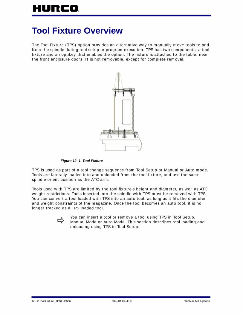
12 - 2 Tool Fixture (TPS) Option 704-0116-410 WinMax Mill Options
Tool Fixture OverviewThe Tool Fixture (TPS) option provides an alternative way to manually move tools to and from the spindle during tool setup or program execution. TPS has two components, a tool fixture and an optikey that enables the option. The fixture is attached to the table, near the front enclosure doors. It is not removable, except for complete removal.
Figure 12–1. Tool Fixture
TPS is used as part of a tool change sequence from Tool Setup or Manual or Auto mode. Tools are laterally loaded into and unloaded from the tool fixture, and use the same spindle orient position as the ATC arm.
Tools used with TPS are limited by the tool fixture’s height and diameter, as well as ATC weight restrictions. Tools inserted into the spindle with TPS must be removed with TPS. You can convert a tool loaded with TPS into an auto tool, as long as it fits the diameter and weight constraints of the magazine. Once the tool becomes an auto tool, it is no longer tracked as a TPS loaded tool.
You can insert a tool or remove a tool using TPS in Tool Setup, Manual Mode or Auto Mode. This section describes tool loading and unloading using TPS in Tool Setup.

WinMax Mill Options 704-0116-410 Tool Fixture (TPS) Option 12-3
Automatic Tool Removal Using TPSFollow the instructions below to use TPS to automatically remove a tool from the spindle:
1. Select the Input console key to access the Input screen.
2. Select the Tool Setup softkey.
3. With the cursor in the Tool field, enter the number of the tool you want to change into the spindle.
4. Select the Auto Tool Change console button. The Start Cycle button begins flashing.
5. Press the Start Cycle console button to initiate the tool removal process. The enclosure doors can now be opened. A "Confirm Empty Fixture. Close Doors and Press Start to Continue" message appears. The Start Cycle button flashes.
6. Make certain the Tool Fixture is empty. Press the Start Cycle button and its stops flashing.
7. A "Remove Tool X from Fixture, Close Doors & Press Start" message appears on the screen.
8. Remove the tool from the fixture, close the enclosure doors and Press the Start Cycle button.
9. The tool entered in step #3 is inserted from the magazine into the spindle.
10. The tool removal is complete. You must use Manual Mode if the tool you are removing was the last tool in the spindle.

12 - 4 Tool Fixture (TPS) Option 704-0116-410 WinMax Mill Options
Automatic Tool Change Using TPSFollow the instructions below to complete an Auto Tool change using TPS
1. Select the Input console button to access the Input screen.
2. Select the Tool Setup softkey to access the Tool Setup screen.
3. With the cursor in the Tool field, enter the number of the tool that will be inserted into the spindle using TPS.
4. Press the Tool Changer Auto console button. The Start Cycle button begins flashing.
5. Press the Start Cycle button to initiate the tool change.
a. The Z axis rapids to the home position. b. The X and Y axes rapid to the Access position. An "Insert Tool X in Fixture.
Press Start" message appears. The Start Cycle button flashes again.
6. Insert the tool into the fixture.
7. Close the enclosure doors. Press the Start Cycle button.
a. The Start Cycle button stops flashing. b. The X and Y axes rapid to the Fixture position. c. The spindle orients (if it is not already oriented). d. The spindle unclamps. e. The Z axis rapids to the Clear position (its position before the tool change
began) - then moves at a fixed, reduced feedrate to the Fixture position. The spindle clamps the tool.
f. The Z-axis moves to the Fixture position at a reduced feedrate. g. The spindle clamps the tool. h. The X and Y axes move to the Clear position (their positions before the tool
change began) at a reduced feedrate. i. The Z axis rapids to the Tool Change position.
8. The tool change is complete.
If the Tool in Spindle is 0, a message will appear confirming that the spindle is empty. If the Tool in Spindle is a number other than 0, the tool will be removed from the spindle (automatically put into the magazine or you will be prompted to be removed manually)
A message requesting the tool be removed from the spindle using TPS will be displayed for any tool that was inserted into the spindle with TPS. You may use TPS to remove the tool or manually unclamp the tool to remove it from the spindle.

WinMax Mill Options 704-0116-410 Tool Fixture (TPS) Option 12-5
Bypass TPS in an Automatic Tool Change Follow the instructions below to complete an Auto Tool change and bypass TPS:
1. Select the Input console button to access the Input screen.
2. Select the Tool Setup softkey to access the Tool Setup screen.
3. With the cursor in the Tool field, enter the number of the tool that will be inserted into the spindle.
4. Press the Tool Changer Auto console button; the Start Cycle button begins flashing. Press the Start Cycle button. If there is a tool in the spindle, remove it before proceeding. If the spindle is empty, the machine moves to the Access position.
5. When prompted to insert the tool into the fixture, manually insert the tool into the spindle. To install a tool using TPS, see Automatic Tool Removal Using TPS, on page 12 - 3.
a. Press the spindle unclamp button and insert the tool. The prompt changes to "Insert Tool XX in Spindle & Press Start Cycle."
b. Release the unclamp button. The tool is clamped in the spindle.
6. Close the enclosure doors and press the Start Cycle button.
7. The tool change is complete. Any tool that is inserted into the spindle manually (bypassing TPS) must be removed manually.

12 - 6 Tool Fixture (TPS) Option 704-0116-410 WinMax Mill Options

WinMax Mill Options 704-0116-410 UltiMotion 13-1
ULTIMOTION
Hurco’s UltiMotion system provides the following benefits:
Improved Surface Quality
With Hurco's proprietary smoothing, lookahead and motion control technology, the UltiMotion system provides significantly improved part surface quality. You'll see smoother and shinier surfaces, less vibration, less chatter marks, and higher accuracy.
Higher Throughput
Compared with a standard motion system, the UltiMotion system's advanced motion planning and rapid corner feature can provide decreased cycle time with the same or even better surface finish quality. This is especially true for parts with complex geometries or large amounts of repeated tasks, such as drilling or tapping.
Rapid Corner
For programs with a lot of consecutive rapid moves, the UltiMotion system doesn't stop between two rapids. Instead, it travels through blended corners at very high speed with only negligible deviation. This saves significant amount of time for repeated tasks, such as drilling and tapping.
Broader Performance Range for Surface Finish Quality
The Surface Finish Quality (SFQ) mechanism is Hurco's proprietary technology to allow users to choose better surface finish or higher throughput for their applications via a simple one-parameter control mechanism. Winmax control automatically adjusts internal parameters to achieve either better surface quality (smaller SFQ) or higher throughput (higher SFQ). The UltiMotion system extends the performance range for SFQ to have even better surface quality for your finish pass and even more time savings in the roughing or semi-roughing passes.
Higher Quality Rigid and Regular Tapping
The UltiMotion system deploys a coordinated motion control mechanism for regular and rigid tapping. You no longer need to worry if your tap will pass go/no-go tests; the UltiMotion system monitors the spindle angle at all times and controls the Z-axis to track the spindle position.
Smoother Motion Results in Longer Machine Life
Rough motion, vibration, and bumping increase mechanical system fatigue and shorten machine life. The UltiMotion system's unique acceleration and jerk control, along with its advanced motion planning, have made it possible to achieve faster, yet smoother motion. You will get a faster machine with extended machine life.
Robust and Consistent Performance Over a Wide Range of Working Conditions
Have you ever had trouble maintaining the equivalent performance with work pieces weighing from several ounces to several thousands of pounds? The UltiMotion system's
13 - 2 UltiMotion 704-0116-410 WinMax Mill Options
advance and accurate model compensation will help you to maintain the same level of performance over a wide range of working conditions.
Dynamic Variable Lookahead Algorithm
Hurco's proprietary Lookahead doesn't require a fixed number of blocks lookahead like conventional controls; instead the lookahead varies dynamically depending on the geometry and motion profile, but always guarantees there is enough to make optimized maneuvers.
Smooth and Responsive Handwheel Jogging
Compared with standard system, the UltiMotion system's hand wheel jogging is optimized to reduce bumping and vibration while providing more responsiveness.

WinMax Mill Options 704-0116-410 UltiNet 14-1
ULTINET
The UltiNet option provides connection to your Local Area Network (LAN) for communication with other CNCs, PCs, or file servers using standard TCP/IP and FTP protocols.
UltiNet FTP Client . . . . . . . . . . . . . . . . . . . . . . . . . . . . . . . . . . . . . . . . . . 14 - 2
UltiNet FTP Server . . . . . . . . . . . . . . . . . . . . . . . . . . . . . . . . . . . . . . . . . 14 - 2

14 - 2 UltiNet 704-0116-410 WinMax Mill Options
UltiNet FTP ClientAny file operation performed by an operator at the machine uses the UltiNet FTP client:
1. From the Input screen, select the PROGRAM MANAGER F8 softkey.
2. From the Program Manager screen, select the FTP MANAGER F8 softkey.
3. Select host from the list and select the CONNECT F1 softkey, or select the ADD HOST F4 softkey to add a connection.
The FTP Manager displays the current connection.
The following tasks can be performed from the FTP Manager screen:
• read a program from the server
• write a program to the server
• copy a program from the server
• copy a program to the server
• rename a program
• delete a program
• create a directory
• delete a directory
UltiNet FTP ServerThe UltiNet FTP server runs as a background task, invisible to the operator, providing access to the Hurco machine from a remote computer. To enable the FTP server:
1. In Auxiliary mode, select the UTILITIES softkey.
2. Select the USER PREFERENCES F2 softkey.
3. Use the MORE softkey to find and select the FTP SERVER SETTINGS F2 softkey.
Once a connection is made, a user may perform the following tasks:
• Transfer files to or from the Hurco machine
• Create a directory
• Delete a directory
• Delete files
• Rename files anywhere in the directory structure

WinMax Mill Options 704-0116-410 UltiNet 14-3
FTP Server Settings
The WinMax console can serve as an FTP Server. These fields appear on the FTP Server Settings screen:
• Enable FTP Server—Enable the WinMax Control to act as an FTP Server.
• FTP Server Port—The port number for FTP access.
• Maximum Idle Time (Mins)—Maximum amount of time before connection is dropped.
• User Name—The log in name that will allow users access to the FTP Server.
• Password—The password that corresponds to the user name and allows access to the FTP Server.
• Path—The file path that the users will be allowed access to.

14 - 4 UltiNet 704-0116-410 WinMax Mill Options

WinMax Mill Options 704-0116-410 UltiPockets Option 15-1
ULTIPOCKETS OPTION
The UltiPocket™ programming option adds special milling routines for machining pocket boundaries with islands. This option provides complete clean out of odd-shaped pockets without cutting the islands programmed inside the boundary. The software automatically calculates the tool path around islands eliminating the long task of plotting these shapes. Islands may also be rotated, scaled, and repeated.
The following drawing shows an inward spiral boundary with three differently shaped islands.
The pocket feature is available for any of these standard WinMax program data blocks, Mill Contour, Mill Frame, Mill Circle, or Patterns.
These topics are discussed in this section:
Pocket Boundary . . . . . . . . . . . . . . . . . . . . . . . . . . . . . . . . . . . . . . . . . . 15 - 2
Helical Plunge with UltiPocket Option . . . . . . . . . . . . . . . . . . . . . . . . . . . . 15 - 4
Helical Plunge Using Operator Specify Pocket Start . . . . . . . . . . . . . . . . . . . 15 - 5
To use the UltiPocket feature, first establish the cutter compensation parameter and then program any UltiPocket data blocks.
• Refer to Milling Parameters.
• Select either Insert Arc or Insert Line for the Cutter Comp Parameter field. If this field does not appear on the Milling Parameters screen, the UltiPocket option has not been installed on the control.

15 - 2 UltiPockets Option 704-0116-410 WinMax Mill Options
Pocket Boundary The Pocket Boundary is the outside frame of the part. The basic philosophy of the UltiPocket option is to program the boundary and then tell the system which pockets or islands to avoid within that boundary. This approach eliminates complex calculations and shortens the part programming process.
There are two types of Pocket Boundaries: Spiral Outward (no islands) and Spiral Inward.
Spiral Outward - No Islands
This selection is only for Circle and Frame data blocks without islands. When this routine is selected, the tool begins from the center region of the part outward to pocket the entire programmed boundary. This operation is, therefore, the same as the standard WinMax Pocket selection. With this selection the cutter overlap is controlled by the Pocket Overlap value on the Milling Parameters screen, not the Pocket Overlap field on the Mill Circle and Mill Frame screens.
Spiral Inward
This selection cuts in from the outside of the defined boundary avoiding the defined islands. When this routine is selected, the tool enters the part and begins following a path formed by offsetting the boundary one-half the tool radius, plus the pocket overlap.
To control the percentage of overlap during cutting, enter a value in the Pocket Overlap field on the Mill Circle or Mill Frame screen. After the first pass, the tool follows a path produced by offsetting the boundary by the tool radius, plus the pocket overlap for each pass while avoiding islands inside the boundary.
After pocketing the boundary, the tool then cuts around the inside of the boundary and the outside of each island, using the selected blend offset and the programmed tool radius.
Programming Islands
After programming the mill data block for a boundary, an island can be defined by creating a Pocket Island data block. As many islands as desired may be defined (subject to computer memory on the control), but all must fit within the defined boundary and should allow the tool to completely define the island.
The island data block can be a Mill Frame, Circle, or Contour (provided it is a closed contour). The Pocket Island data blocks use the standard milling values from the boundary data block and do not display these parameters on the island programming screen. The pocket overlap percentage was also defined in the boundary data block.

WinMax Mill Options 704-0116-410 UltiPockets Option 15-3
Mill Contours
To create a Mill Contour data block using the UltiPocket option, set up the operation in the start segment (segment zero). As in standard WinMax milling, an UltiPocket Mill Contour block consists of segments beginning with segment zero. With the cursor in the MILLING TYPE field, select one of the Pocket options in the Start segment to indicate whether this block is the boundary of the part or one of the islands within the boundary. The boundary must occur first in the program.
The segments after the Start segment are programmed in the same manner as standard milling lines and arcs. Automatic calculation of unknown points is available for these data blocks.
Mill Frame
The Mill Frame data block is often used to create the part boundary.
This block is programmed in the same manner as the standard WinMax Mill Frame, with the addition of the Pocket Overlap percentage.
Mill Circle
The Mill Circle data block is used for both boundaries and islands. It is similar to the standard Mill Circle data block except that if this block is used to create an island, it uses the tool from the boundary data block.
Pattern
Pattern data blocks can be inserted to rotate, scale, or repeat islands. Only Pattern data blocks can be programmed between a boundary data block and an island. As many islands as desired may be defined (subject to available memory), but all must fit within the defined boundary.

15 - 4 UltiPockets Option 704-0116-410 WinMax Mill Options
Helical Plunge with UltiPocket Option The Helical Plunge option is used with the UltiPocket option to define the plunging location when inward pocketing. Islands created using inward pocketing can influence plunge locations. A plunge location is determined that will not interfere with pocket islands.
The plunging location in outward pocketing is the same as a straight plunge. Outward pocketing is used only for mill frame, mill circle, and ellipse pocket boundaries that do not have pocket islands. Since islands are not present with outward pocketing, the plunging location is in the middle of the mill frame, mill circle and ellipse.
When the Helical Plunge option is installed, two additional pocketing-related fields appear on the Milling Parameters screen. These fields are Operator Specify Pocket Start and Inward Pocket Plunge Near Center.
The Operator Specify Pocket Start field takes precedence over the Inward Pocket Plunge Near Center field. If the Operator Specify Pocket Start field is set to Yes, the value of the Inward Pocket Plunge Near Center field is ignored.
When the Operator Specify Pocket Start field is set to No, the value of the Inward Pocket Plunge Near Center field is checked. If the Inward Pocket Plunge Near Center field is set to Yes, a starting location will be determined near the center of the pocket. If both fields are set to No, the default starting position will be used for the pocket.

WinMax Mill Options 704-0116-410 UltiPockets Option 15-5
Helical Plunge Using Operator Specify Pocket Start To use the Operator Specify Pocket Start function:
1. Set the Type field to Pocket Boundary on the Mill Contour, Mill Frame or Mill Circle screen.
2. Set the Pocket Type field to Inward on the Mill Contour, Mill Frame or Mill Circle screen.
3. Set the Operator Specify Pocket Start field to Yes on the Milling Parameters screen.
4. The Pocket X Start and Pocket Y Start fields appear on the Mill Contour, Mill Frame, or Mill Circle screen. The operator identifies the pocket plunge location with the Pocket X Start and Pocket Y Start fields. The Pocket X Start and Pocket Y Start fields define the centerline of the plunge path. This is the location where the helix will be centered. If a straight plunge is selected, the straight plunge will occur at the location.
The following figure shows the Pocket X Start and Pocket Y Start fields on the Mill Frame screen. See the "Helical Plunge Option" chapter for an example using Pocket Start X and Pocket Start Y fields.
For non-rotary blocks, Pocket X Start and Pocket Y Start define the XY starting location. For rotary blocks, these fields define the XA starting location.
An error message will display if the values for Pocket X Start or Pocket Y Start interfere with the pocket island or pocket boundary.

15 - 6 UltiPockets Option 704-0116-410 WinMax Mill Options

WinMax Mill Options 704-0116-410 Record of Changes — 1
RECORD OF CHANGES
704-0116-410 rB, February 2010
Revised by: H.Arle
Approved by: D.Skrzypczak, February 2010
704-0116-410 rA, December 2009
Revised by: H.Arle
Approved by: D.Skrzypczak, Dec 2009
Changes
• Added UltiMotion.
• Updated to reflect software changes from v7.3.
Changes
• Added Custom Drill.
• Added Mill Polygon.
• Added HD3 Serial Numbeing Lettering.
• Added Contour Arc content.
• Added Lettering Reference Locations content.
• Added Mill Slot.
• Added Thread Mill.
• Updated to reflect software changes from v7.3.

- 2 Record of Changes 704-0116-410 WinMax Mill Options

Machine WinMax Mill Options 704-0116-410 Index — 1
INDEX
Numerics3D Mold 1 - 1
Blend Arc 1 - 12Contour 1 - 9Line 1 - 10Parameters 1 - 2
AA Angle field
Rotary Lines and Arcs Start Segment 6 -14
Rotary Position block 6 - 11A Center field
Rotary Circle block 6 - 16Rotary Lines and Arcs Arc Segment 6 -
15Rotary Lines and Arcs Blend Arc
Segment 6 - 15A Corner field
Rotary Frame block 6 - 16A Distance field
Rotary Loop block 6 - 17, 6 - 22A End field
Rotary Lines and Arc Blend Arc Segment 6 - 15
Rotary Lines and Arcs Arc Segment 6 -15
Rotary Lines and Arcs Line Segment 6 -14
A Length fieldRotary Frame block 6 - 16
A Start fieldRotary Lines and Arcs Arc Segment 6 -
15Rotary Lines and Arcs Blend Arc
Segment 6 - 15Rotary Lines and Arcs Line Segment 6 -
14A-axis rotation 6 - 2Absolute Location 8 - 11Accept softkey, DXF 3 - 3, 3 - 7All Off, DXF 3 - 9All On, DXF 3 - 9Angle Center field 6 - 34
Arc SegementUniversal Rotary 6 - 33
Angle Distance field 6 - 37Angle End field 6 - 33
Angle fieldMill Slot Geometry tab 9 - 3
Angle Length field 6 - 35Angle Start field 6 - 33, 6 - 35Approach Feed, Part Probing Parameters
8 - 5Arc Radius field 6 - 28Assure 4 - 4Assure Minimum Length
HD3 Serial Number Lettering Format tab 4 - 4
AutochainContours, DXF 3 - 5DXF 3 - 3
Automatic Mode 8 - 23Automatic Part Zero Cycles, Probing 8 - 24Automatic Skew Cycles, Probing 8 - 25Automatic Tool Change Using TPS 12 - 4Automatic Tool Removal Using TPS 12 - 3Axis Center field 6 - 34Axis Configuration 6 - 4Axis Distance field 6 - 37Axis End field 6 - 33Axis Length field 6 - 35Axis of Rotation 6 - 40Axis Start field 6 - 33, 6 - 35
BB Distance field 6 - 17, 6 - 24Ball-Nosed End Mill 1 - 16
on a Contour 1 - 14B-axis rotation 6 - 2Beam Offset parameter, Tool Probe Setup
Parameters 8 - 4Bidirectional field
3D Mold Paratmeters 1 - 6Blend Type field
Thread Mill block 10 - 3Block field
3D Mold Arc 1 - 113D Mold Blend Arc 1 - 123D Mold Contour 1 - 93D Mold Line 1 - 103D Mold Paratmeters 1 - 2Probe Part Setup 8 - 17Tool Monitoring screen 8 - 29
Bottom Tab, Custom Drill 2 - 5Break Out Tab, Custom Drill 2 - 4Breakage Tolerance field, Tool Monitoring
screen 8 - 29Build DB softkey 3 - 3Bypass TPS in an Automatic Tool Change
12 - 5

2 - Index 704-0116-410 Machine WinMax Mill Options
CC Angle field 6 - 19, 6 - 27C Center field 6 - 20
Arc segmentAC Configuration 6 - 20BC configuration 6 - 28
Blend Arc segmentBC Configuration 6 - 28
Circle blockAC Configuration 6 - 21BC Configuration 6 - 29
C Corner field 6 - 21, 6 - 29C Distance field 6 - 22, 6 - 30C End field 6 - 19, 6 - 20, 6 - 27, 6 - 28C End field, Arc Segement, AC configura-
tion 6 - 20C End field, Arc segment, BC configuration
6 - 27C Length field 6 - 21C Length field, Rotary Frame, BC configura-
tion 6 - 29C Start field 6 - 19, 6 - 20, 6 - 27, 6 - 28
Rotary Lines and Arcs Arc Segment 6 -20, 6 - 28
Cal Tool D parameter, Tool Probe Setup Pa-rameters 8 - 4
Cal Tool H parameter, Tool Probe Setup Pa-rameters 8 - 4
Cal Tool L parameter, Tool Probe Setup Pa-rameters 8 - 4
calculate X and Z-axis positions after a tilt-axis move, tilt-axis program, WinMax Mill 6 - 41
calculator, on-screen - xiiCalibrate the Tool Probe softkey 8 - 15C-axis rotation 6 - 2Center Beam X parameter, Tool Probe Set-
up Parameters 8 - 3Center Beam Y parameter, Tool Probe Set-
up Parameters 8 - 3Center X field
Cylinder Cycle 8 - 40Hole or Circle Pocket Probing Cycle 8 -
38Rectangluar Pocket Cycle 8 - 42Rectangular Solid Outside Cycle 8 - 44
Center X, DXF 3 - 8Center Y field
Cylinder Cycle 8 - 40Hole or Circle Pocket Probing Cycle 8 -
38Rectangluar Pocket Cycle 8 - 42Rectangular Solid Outside Cycle 8 - 44
Center Y, DXF 3 - 8Centerline Y field, 3D Mold Paratmeters 1 -
3Centerline Z field, 3D Mold Paratmeters 1 -
3Character Height
HD3 Serial Number Lettering Text tab 4 - 2
Character WidthHD3 Serial Number Lettering Text tab
4 - 2Circular Passes, Part Probing Parameters
8 - 5configuration of Hurco machining centers
6 - 3Contact Point X parameter, Tool Probe Set-
up Parameters 8 - 3Contact Point Y parameter, Tool Probe Set-
up Parameters 8 - 3control
power on - xiiConversational Part Probing Cycles 8 - 19Corner Radius field 6 - 16, 6 - 21, 6 - 29,
6 - 35Mill Polygon block 7 - 3Mill Slot Caps tab 9 - 5
Corner X field, Plane Intersection (Non-Rectangular Corner) Cycle 8 - 46
Corner Y field, Plane Intersection (Non-Rectangular Corner) Cycle 8 - 46
create a rotary-axis or tilt-axis program from an existing Conversational pro-gram 6 - 4
Custom Drill 2 - 1Cut Comp Enable field
Thread Mill block 10 - 3Cut Direction field
3D Mold Paratmeters 1 - 5Cutter Type field
Thread Mill block 10 - 2Cylinder and Hole or Circle Inspection cy-
cle, Probing 8 - 27Cylinder and Rectangular Solid Inspection
cycle, Probing 8 - 27Cylinder Cycle 8 - 24, 8 - 33, 8 - 40Cylinder cycle
Probing 8 - 20Cylinder Radius field 6 - 13Cylinder Skew Cycle 8 - 25, 8 - 34, 8 - 50
DData Origin
HD3 Serial Number Lettering Text tab
Machine WinMax Mill Options 704-0116-410 Index — 3
4 - 2Default Order
softkey 3 - 3, 3 - 4Default Radius
DXF 3 - 3Delete softkey
DXF 3 - 8Determine Laser Beam Offset softkey,
Probing 8 - 3, 8 - 10Diameter field
Cylinder Cycle 8 - 40Hole or Circle Pocket Probing Cycle 8 -
38Diameter Tolerance field
Tool Monitoring screen 8 - 29Direction field 6 - 14, 6 - 15, 6 - 19, 6 - 20,
6 - 27, 6 - 28, 6 - 33, 6 - 343D Mold Arc 1 - 113D Mold Blend Arc 1 - 12DXF 3 - 8Mill Slot Geometry tab 9 - 4Tool Monitoring screen 8 - 29
Disable Start Location field 6 - 6, 6 - 11Display Geometry, DXF 3 - 5Draw 2D Contour 1 - 2Draw console key 3 - 2DXF
Editor 3 - 2Layers 3 - 9
DXF Edit ModifyArc 3 - 8Line 3 - 8Point 3 - 8
DXF Option 3 - 1
EEdge (X, Y, or Z) field, Edge Probing Cycle
8 - 36Edge Cycle 8 - 33, 8 - 35
Probing 8 - 20Edge Skew Cycle 8 - 25, 8 - 34, 8 - 48Edit 3D Mold Parameters softkey 1 - 9Edit Drawing
DXF 3 - 3, 3 - 5Emergency Stop - xiiEnable field
Custom Drill Break Out tab 2 - 4Custom Drill Out tab 2 - 7Custom Drill Re-entry tab 2 - 6Custom Drill Retract tab 2 - 8
Enable FTP Server field 14 - 3End Angle field, 3D Mold Paratmeters 1 - 4End Cap field
Mill Slot Caps tab 9 - 4Endpoint Tolerance, DXF 3 - 5Endpoint1 X, DXF 3 - 8Endpoint1 Y, DXF 3 - 8Endpoint2 X, DXF 3 - 8Endpoint2 Y, DXF 3 - 8Entry Tab, Custom Drill 2 - 3error messages - xiiExit/Cancel
DXF 3 - 3Explode PCurve softkey, DXF 3 - 8Extend softkey, DXF 3 - 6
FFast Feed field, Tool Setup Probing 8 - 16Feed field
Custom Drill Break Out tab 2 - 4Custom Drill Entry Tab 2 - 3Custom Drill Out tab 2 - 7Custom Drill Re-entry tab 2 - 6Custom Drill Retract tab 2 - 8Custom Tool Bottom tab 2 - 5
feeler gauge 8 - 12fields
Part Setup, rotary-axis program, WinMax Mill 6 - 8
FileHD3 Serial Number Lettering Text tab
4 - 3Finish Diameter field
3D Mold Paratmeters 1 - 8Finish Plunge Helix Radius field, Helical
Plunge Milling Parameters 5 - 2Finish Plunge Ramp Slope field, Helical
Plunge Milling Parameters 5 - 2Finish Plunge Type field, Helical Plunge Mill-
ing Parameters 5 - 2Finish Step Size field, 3D Mold Paratmeters
1 - 7Finish Tool field
3D Mold Paratmeters 1 - 2Finish Tool Type field, 3D Mold Paratmeters
1 - 8Fit to View softkey
DXF 3 - 5Flat End Mill 1 - 15
on a Contour 1 - 13Frame Radius 3 - 5FTP Client 14 - 2FTP Manager 14 - 2FTP Server 14 - 2
Port field 14 - 3FTP Server Settings 14 - 3

4 - Index 704-0116-410 Machine WinMax Mill Options
HHD3 Serial Number Lettering block 4 - 1Helical Plunge (Inside/Outside) for Mill
Frames, Mill Circles and Ellipses 5 - 3Helical Plunge in the Center of a Pocket 5 -
3Helical Plunge Milling Parameter Fields 5 -
2Helical Plunge of Mill Frame Inside with No
Pecking and Blend Offset 5 - 4Helical Plunge Option 5 - 1Helical Plunge Using Operator Specify Pock-
et Start 15 - 5Helical Plunge with 3-D Part Programming
Option 5 - 7Helical Plunge with Lines and Arcs 5 - 7Helical Plunge with Operator Specified Lo-
cation 5 - 3Helical Plunge with Outward Pocketing 5 - 4Helical Plunge with UltiPocket 5 - 3, 15 - 4Helical Plunging of Mill Frame Inside with
Pecking and Straight Plunge Finish Pass and Blend Offset 5 - 5
helix thread program example, WinMax Mill 6 - 44
Hole Diameter 3 - 5Hole or Circle Pocket Cycle 8 - 24, 8 - 33,
8 - 38, 8 - 39Probing 8 - 20
Hole or Circle Pocket Skew Cycle 8 - 25, 8 -34, 8 - 49
Holes softkeyDXF 3 - 3
Iicons - xiiiINCR Retract, probe part setup 8 - 6INCR Retract, touch probe tool setup 8 - 3Increased Radius 1 - 3Increment
HD3 Serial Number Lettering Text tab 4 - 2
INIT Retract, probe part setup 8 - 6INIT Retract, touch probe tool setup 8 - 3Inner Diameter, Mill Polygon 7 - 2Internal Thread field
Thread Mill block 10 - 2Intersect softkey 3 - 3, 3 - 4Inward Pocket Plunge Near Center field,
Helical Plunge Milling Parameters 5 -2
Island, Pocket 15 - 2
JJoin softkey, DXF 3 - 7Joined Lines and Arcs 3 - 7
LLaser Beam Calibration 8 - 9Laser Probe softkey, Probing 8 - 3Laser Tool Calibration
Calculations 8 - 9Cycle 8 - 10
Leading SymbolHD3 Serial Number Lettering Format
tab 4 - 4Length (X) field
Rectangluar Pocket Cycle 8 - 42Rectangular Solid Outside Cycle 8 - 44
Length (Y) fieldRectangluar Pocket Cycle 8 - 42Rectangular Solid Outside Cycle 8 - 44
Length fieldMill Slot Geometry tab 9 - 3
Length, DXF 3 - 8
Mmachining center configuration 6 - 3Maintain Finishing Sequence field
Tool Change Optimization 11 - 2Maintain Roughing Sequence field
Tool Change Optimization 11 - 2Manual Mode Part Setup Probing Cycles 8 -
20Manual Mode Part Skew Probing Cycles 8 -
21Manual Tool Probing Cycles 8 - 30Max Deflection
probe part setup 8 - 6probe tool setup 8 - 4
Max Spread fieldPart Probing Parameters 8 - 5Tool Probe Setup Parameters 8 - 3
Maximum Idle Time (Mins) field 14 - 3Measurement Feed, Part Probing Parame-
ters 8 - 5messages
error - xiiMill 7 - 1Mill Circle 15 - 3Mill Contours 15 - 3Mill Feed field
3D Mold Paratmeters 1 - 8Mill Frame 15 - 3
Machine WinMax Mill Options 704-0116-410 Index — 5
Mill Plunge Helix Radius field, Helical Plunge Milling Parameters 5 - 2
Mill Plunge Ramp Slope field, Helical Plunge Milling Parameters 5 - 2
Mill Plunge Type field, Helical Plunge Milling Parameters 5 - 2
Mill Polygon 7 - 1Mill Slot 9 - 1Mill Thread data block 10 - 1Milling softkey
DXF 3 - 3Min Z field
3D Mold Paratmeters 1 - 7Minimum Length
HD3 Serial Number Lettering Format tab 4 - 4
Minimum Z field, Tool Setup Probing 8 - 16mode
programming - xiiModify softkey, DXF 3 - 7Monitor Motion
probe part setup 8 - 6touch probe tool setup 8 - 3
Multi-Tool Probing field 8 - 31Tool Setup Probing 8 - 16
Nnested Pattern Loop data blocks, rotary-
axis program 6 - 17nested Pattern Loop data blocks, rotary-
axis program, WinMax Mill 6 - 22, 6 -25, 6 - 30, 6 - 38
Number field 6 - 17, 6 - 22, 6 - 24, 6 - 30, 6 - 37
Number Of Sides fieldMill Polygon block 7 - 1
OOffset 1 field, Plane Intersection (Non-Rect-
angular Corner) Cycle 8 - 46Offset 2 field, Plane Intersection (Non-Rect-
angular Corner) Cycle 8 - 46Offset X/Y field, Probe Part Setup 8 - 17on-screen calculator - xiiOperator Specify Pocket Start field, Helical
Plunge Milling Parameters 5 - 2Orientation Angle field
Mill Polygon block 7 - 2Out Tab, Custom Drill 2 - 7Outer Diameter, Mill Polygon 7 - 2
PPan softkey
DXF 3 - 5Part Inspection Cycles 8 - 26, 8 - 28Part Inspection Fields, Probing 8 - 26Part Inspection Programming, Probing op-
tion 8 - 28Part Probe Calibration 8 - 12Part Probe Cycle field
Cylinder Cycle 8 - 40Edge Probing Cycle 8 - 36Hole or Circle Pocket Probing Cycle 8 -
38Rectangluar Pocket Cycle 8 - 43Rectangular Solid Outside Cycle 8 - 44
Part Probe Deflection 8 - 2Offset 8 - 13Offset Calibration 8 - 13
Part Probe Working Envelope 8 - 2Part Probing Cycles 8 - 19Part Probing Parameters 8 - 5Part Setup
fields 8 - 19Part X Offset, DXF 3 - 5Part Y Offset, DXF 3 - 5Part Zero Cycle field, Probe Part Setup 8 -
17part zero different for Transformed Planes
program example 6 - 56part zero does not change for Transformed
Planes program example 6 - 54Part Zero Storage Cycle 8 - 20Part Zero X, Y fields 8 - 19Password field 14 - 3Path field 14 - 3Pattern 15 - 3Pattern End, Rotary A and Rotary A Tilrt B
configurations 6 - 13Pattern Locations softkey 3 - 4Pattern Loop data blocks, nesting, rotary-
axis program, WinMax Mill 6 - 22, 6 -25, 6 - 30, 6 - 38
Peck Depth field3D Mold Paratmeters 1 - 7Custom Drill Tool Tab 2 - 2
Peck Type fieldCustom Drill Tool Tab 2 - 2
Pitch fieldThread Mill block 10 - 2
Plane Intersection (Non-Rectangular Cor-ner) Cycle 8 - 24, 8 - 33, 8 - 46
Plane Intersection cycle, Probing 8 - 20Plane Intersection Inspection cycle, Probing

6 - Index 704-0116-410 Machine WinMax Mill Options
8 - 27Plunge Feed field
3D Mold Paratmeters 1 - 8Pocket Boundary 15 - 2Pocket Island 15 - 2Polygon Milling Data Block 7 - 1Position softkey
DXF 3 - 4Position Tool Over the Probe softkey 8 - 15power-on
control - xiiPresent, Part Probing Parameters 8 - 5Preset X and Preset Y field
Cylinder Cycle 8 - 41Hole or Circle Pocket Probing Cycle 8 -
39Plane Intersection (Non-Rectangular
Corner) Cycle 8 - 46Rectangular Solid Outside Cycle 8 - 45
Preset X or Preset Y fieldEdge Probing Cycle 8 - 36Rectangluar Pocket Cycle 8 - 43
Preset X/Y fieldProbe Part Setup 8 - 17, 8 - 18
printing - xiiiProbe A Single Tool softkey 8 - 15, 8 - 30Probe Current Tool Now softkey 8 - 15Probe Cycle Type field, Tool Monitoring
screen 8 - 29Probe Direction X/Y field, Probe Part Setup
8 - 17, 8 - 18Probe Multiple Tools softkey 8 - 15, 8 - 31Probe Part Setup 8 - 17
data block 8 - 19, 8 - 23data block execution 8 - 26fields 8 - 23
Probe Tool Monitoring 8 - 28Probe Z 8 - 19Probing Axis field, Edge Probing Cycle 8 -
36Probing Axis parameter, Tool Probe Setup
Parameters 8 - 3Probing Cycles 8 - 33, 8 - 34Probing Direction field, Edge Probing Cycle
8 - 36Probing Direction X field, Plane Intersection
(Non-Rectangular Corner) Cycle 8 -46
Probing Direction Y field, Plane Intersection (Non-Rectangular Corner) Cycle 8 -46
Probing Equipment 8 - 2Probing Length X field, Rectangular Solid
Outside Cycle 8 - 44Probing Length X/Y field, Probe Part Setup
8 - 17, 8 - 18Probing Length Y field, Rectangular Solid
Outside Cycle 8 - 45Probing Method field, Tool Monitoring
screen 8 - 29Probing Option 8 - 1Probing Radius field
Cylinder Cycle 8 - 41Probe Part Setup 8 - 17, 8 - 18
program status - xii
RRadius 6 - 34Radius Bottom field 6 - 27, 6 - 29, 6 - 33,
6 - 34, 6 - 35Radius End field 6 - 27, 6 - 33Radius End field, Arc segment, BC configu-
ration 6 - 28Radius field 6 - 15, 6 - 16, 6 - 20, 6 - 21,
6 - 28, 6 - 29, 6 - 343D Mold Arc 1 - 113D Mold Blend Arc 1 - 12Mill Slot Geometry tab 9 - 3Thread Mill block 10 - 2
Radius Start field 6 - 27, 6 - 29, 6 - 33, 6 -34, 6 - 35
Radius Start field, Arc segment, BC config-uration 6 - 28
Radius, DXF 3 - 8Rapid Z Position field, Tool Setup Probing
8 - 16Rectangular Pocket and Rectangular Solid
Inspection cycle, Probing 8 - 27Rectangular Pocket cycle, Probing 8 - 20Rectangular Pocket Inside Cycle 8 - 33, 8 -
42Rectangular Pocket Skew Cycle 8 - 24, 8 -
25, 8 - 34, 8 - 51Rectangular solid cycle, Probing 8 - 20Rectangular Solid Outside Cycle 8 - 24, 8 -
33, 8 - 44Rectangular Solid Skew Cycle 8 - 24, 8 -
25, 8 - 34, 8 - 52Re-entry Tab, Custom Drill 2 - 6Reference Block 8 - 14Reference Tool Touch 8 - 11Repetitions parameter, Tool Probe Setup
Parameters 8 - 3Repetitions, Part Probing Parameters 8 - 5Reset Probe Work region to Maximum soft-
key, Part Setup screen 8 - 5

Machine WinMax Mill Options 704-0116-410 Index — 7
Retract Feed parameter, Tool Probe Setup Parameters 8 - 3
Retract Tab, Custom Drill 2 - 8Reverse, DXF 3 - 3Ring Gauge 8 - 13Rotary Axis machining 6 - 3Rotary Centerline 6 - 8Rotary Circle softkey 6 - 12Rotary Circle, BC configuration 6 - 28Rotary Frame softkey 6 - 12Rotary Lines and Arcs softkey 6 - 12Rotary Locations, AC configuration 6 - 22Rotary Locations, Rotary A and Rotary A Til-
rt B configurations 6 - 12Rotary Loop field, Rotary A and Rotary A
Tilrt B configurations 6 - 12Rotary Loop, AC configuration 6 - 21Rotary Loop, BC configuration 6 - 24, 6 -
29Rotary Mill Frame program example, Win-
Max Mill 6 - 43Rotary Milling field 6 - 10Rotary Orientation field 6 - 40Rotary Parameters field 6 - 10Rotary Parameters, AC configuration 6 - 23Rotary Part Setup 6 - 8Rotary Pattern End, AC configuration 6 - 23Rotary Pattern Loop program example,
WinMax Mill 6 - 46Rotary Patterns field 6 - 10Rotary Patterns, BC configuration 6 - 24,
6 - 29Rotary Position
Tool, rotary-axis program, WinMax Mill 6 - 12
Rotary Position field 6 - 10Rotary Safety Move field 6 - 11Rotary Transform Plane, AC configuration
6 - 23Rotary True Type Font 6 - 12Rotary, overview 6 - 2rotary-axis hardware 6 - 2rotary-axis table 6 - 3Roughing and Finishing
Passes 1 - 17Tools 1 - 13
Ssample screens - xiscreens
Part Setup, rotary-axis program, WinMax Mill 6 - 8
Transform Plane End, rotary-axis
program, WinMax Mill 6 - 5Transform Plane, rotary-axis program,
WinMax Mill 6 - 5Segment field
3D Mold Arc 1 - 113D Mold Blend Arc 1 - 123D Mold Contour 1 - 93D Mold Line 1 - 10
Select Holes by Diameter, DXF 3 - 5Select Layer 3 - 9Select Tool Probe Cycle softkey 8 - 15Serial Number block 4 - 1Serial Port Settings 14 - 3setting axis configuration 6 - 4Setup Fast Feed parameter, Tool Probe Set-
up Parameters 8 - 3Shape field
Mill Slot Start tab 9 - 2Side Clearance field, Tool Setup Probing 8 -
16Side Length field
Mill Polygon block 7 - 2Side Length, Mill Polygon 7 - 2single hole program example, WinMax Mill
6 - 45Single Point and Plane Intersection Inspec-
tion cycle, Probing 8 - 27Single Point Inspection, Probing 8 - 27Sister Tool field
Tool Monitoring screen 8 - 29Tool Setup Probing 8 - 16
Sizing Diameter fieldMill Polygon block 7 - 2
Sizing Method fieldMill Polygon block 7 - 2
Skew Cycle field, Probe Part Setup 8 - 18Skew cycles 8 - 21Skew Start X/Y/Z field, Probe Part Setup 8 -
18Slot Milling Data Block 9 - 1Slow Feed field, Tool Setup Probing 8 - 16Speed (RPM) field
3D Mold Paratmeters 1 - 8Tool Monitoring screen 8 - 29
Speed fieldCustom Drill Break Out tab 2 - 4Custom Drill Entry Tab 2 - 3Custom Drill Out tab 2 - 7Custom Drill Re-entry tab 2 - 6Custom Drill Retract tab 2 - 8Custom Tool Bottom tab 2 - 5
Spindle RPM field, Tool Setup Probing 8 -16
Spindle Usage field
8 - Index 704-0116-410 Machine WinMax Mill Options
Tool Monitoring screen 8 - 29Tool Setup Probing 8 - 16
Split softkey, DXF 3 - 8Start Angle 1, 2, 3 field
Cylinder Cycle 8 - 41Hole or Circle Pocket Probing Cycle 8 -
39Probe Part Setup 8 - 17
Start Angle field3D Mold Paratmeters 1 - 4Thread Mill block 10 - 3
Start Angle, DXF 3 - 8Start At Center field
Thread Mill block 10 - 3Start Cap field
Mill Slot Caps tab 9 - 4Starting Sequence
HD3 Serial Number Lettering Text tab 4 - 2
status, program - xiiStep Size field
3D Mold Paratmeters 1 - 7Stock Allowance field
3D Mold Paratmeters 1 - 8Stop field 6 - 11Store Calculated Value softkey 1 - 10, 1 -
11Store Machine Position softkey
Part Setup screen 8 - 5Probing 8 - 2
Stylus Diameter, Part Probing Parameters 8 - 5
Stylus Width parameter, Tool Probe Setup Parameters 8 - 3
Sweep Angle3D mold Arc block 1 - 11Rotary AC 6 - 20Rotary BC 6 - 28Universal Rotary 6 - 34
Sweep Angle field 6 - 15Mill Slot Geometry tab 9 - 3
Sweep Angle, DXF 3 - 8
TThread Dir field
Thread Mill block 10 - 2Thread Mill 10 - 1Thread Milling Data Block 10 - 1Thread Taper Angle field
Thread Mill block 10 - 3tilt axis at 45 degrees program example,
WinMax Mil 6 - 52Tilt Axis machining 6 - 3
tilt-axis at 90 degrees program example, WinMax Mill 6 - 51
tilt-axis hardware 6 - 2tilt-axis table 6 - 3Tool
Rotary Position, rotary-axis program, WinMax Mill 6 - 12
Tool Change Optimization 11 - 1Tool Change Optimization Off block 11 - 1,
11 - 3Tool Change Optimization On block 11 - 1Tool Change Optimization parameter 11 - 1Tool Diameter field
3D Mold Paratmeters 1 - 8Tool field
3D Mold Paratmeters 1 - 2Custom Drill Tool Tab 2 - 1Probe Part Setup 8 - 17Tool Monitoring screen 8 - 29
Tool Fixture (TPS) Option 12 - 1Tool Probe Calibration 8 - 6Tool Probe Deflection Offset 8 - 11
Calibration 8 - 11softkey, Probing 8 - 2
Tool Probe Setup Parameters 8 - 2softkey 8 - 15
Tool Removal 12 - 3Tool Setup
Probing Fields 8 - 16Probing Softkeys 8 - 15
Tool Tab, Custom Drill 2 - 1Tool Type field
3D Mold Paratmeters 1 - 8Tool Wear Detection Data Block 8 - 32Touch Tool and Part Probe Calibration 8 - 8Touch Tool Probe Calibration 8 - 7TPI field
Thread Mill block 10 - 2Transform Plane 6 - 5
orientation, rotary-axis program, WinMax Mill 6 - 5
part zero location, rotary-axis program, WinMax Mill 6 - 5
Transform Plane End, Rotary A and Rotary A Tilrt B configurations 6 - 12
Transform Plane program example, Win-Max Mill 6 - 47
Transform Plane Reference Points 6 - 6Transform Plane, Rotary A and Rotary A Til-
rt B configurations 6 - 12Transfrom Part Zero field 6 - 11travel limits, Probing 8 - 2Trim softkey, DXF 3 - 8

Machine WinMax Mill Options 704-0116-410 Index — 9
True-Type Fonts 6 - 36Type field
3D Mold Paratmeters 1 - 2Type parameter, Tool Probe Setup 8 - 3
UUltiMotion 13 - 1UltiNet 14 - 1UltiNet FTP Client 14 - 2UltiNet FTP Server 14 - 2UltiPockets Option 15 - 1units of measure - xiiUse Hole Location Method softkey 3 - 3Use Hole Pattern Method softkey 3 - 3Use Offset Z field 6 - 6, 6 - 11User Name field 14 - 3using this manual - xi
WWidth field
Mill Slot Start tab 9 - 2Window Select softkey 3 - 3, 3 - 4
XX Center field 6 - 15, 6 - 16
3D Mold Arc 1 - 113D Mold Blend Arc 1 - 12Mill Polygon block 7 - 1Mill Slot Geometry tab 9 - 3Thread Mill block 10 - 2
X Corner field 6 - 16X Distance field 6 - 17, 6 - 22X End field 6 - 14, 6 - 15
3D Mold Arc 1 - 113D Mold Blend Arc 1 - 123D Mold Line 1 - 10Mill Slot Geometry tab 9 - 3Mill Slot Geomtry tab 9 - 3
X Length field 6 - 16X Min, X Max, Part Probing Parameters 8 - 5X Position field 6 - 11X Ref Location
HD3 Serial Number Lettering Orientation tab 4 - 3
X ReferenceHD3 Serial Number Lettering Text tab
4 - 2X Safety Position field 6 - 11X Start 6 - 14X Start field 6 - 14, 6 - 15
3D Mold Arc 1 - 11
3D Mold Blend Arc 1 - 123D Mold Contour 1 - 93D Mold Line 1 - 10Mill Slot Start tab 9 - 2
X Start X/Y/Z field, Probe Part Setup 8 - 18X Value, DXF 3 - 8X/Y Skew (deg.) 8 - 19XY Angle field
3D Mold Line 1 - 10XY Angle, DXF 3 - 8XY Length field
3D Mold Line 1 - 10XY Start X/Y/Z field, Probe Part Setup 8 -
18XZ Angle field, 3D Mold Line 1 - 10XZ Length field, 3D Mold Line 1 - 10XZ Revolved about Z 1 - 2XZ Translated in Y 1 - 2
YY Center field 6 - 20, 6 - 21
3D Mold Arc 1 - 113D Mold Blend Arc 1 - 12Mill Polygon block 7 - 1Mill Slot Geometry tab 9 - 3Thread Mill block 10 - 2
Y Corner field 6 - 21Y End Field 6 - 19Y End field 6 - 20
3D Mold Arc 1 - 113D Mold Blend Arc 1 - 123D Mold Line 1 - 103D Mold Paratmeters 1 - 5Mill Slot Geometry tab 9 - 3
Y End, Arc Segement, AC configuration 6 -20
Y Length field 6 - 21Y Min, Y Max, Part Probing Parameters 8 - 5Y Off of Centerline field 6 - 13Y Position field 6 - 11Y Ref Location
HD3 Serial Number Lettering Orientation tab 4 - 3
Y ReferenceHD3 Serial Number Lettering Text tab
4 - 2Y Revolved about X 1 - 2Y Safety Position field 6 - 11Y Start field 6 - 19, 6 - 20
3D Mold Arc 1 - 113D Mold Blend Arc 1 - 123D Mold Contour 1 - 93D Mold Line 1 - 10

10 - Index 704-0116-410 Machine WinMax Mill Options
3D Mold Paratmeters 1 - 5Mill Slot Start tab 9 - 2
Y Start X/Y/Z field, Probe Part Setup 8 - 18Y Value, DXF 3 - 8
ZZ Bottom
HD3 Serial Number Lettering Text tab 4 - 2
Z Bottom field 6 - 14, 6 - 16, 6 - 19, 6 - 21Custom Tool Bottom tab 2 - 5Mill Polygon block 7 - 3Mill Slot Start tab 9 - 2
Z Break Out fieldCustom Drill Break Out tab 2 - 4
Z Center field 6 - 283D Mold Arc 1 - 113D Mold Blend Arc 1 - 12
Z Center field, Arc segment, BC configura-tion 6 - 28
Z Corner field 6 - 29Z Depth field
Cylinder Cycle 8 - 41Probe Part Setup 8 - 17, 8 - 18Rectangular Solid Outside Cycle 8 - 45
Z Distance field 6 - 24, 6 - 30Z Drop Down Depth field, Tool Setup Prob-
ing 8 - 16Z End field 6 - 14, 6 - 15, 6 - 19, 6 - 27,
6 - 283D Mold Arc 1 - 113D Mold Blend Arc 1 - 123D Mold Line 1 - 10
Z End field, Arc segment, BC configuration 6 - 27
Z End, Arc Segement, AC configuration 6 -20
Z Home 6 - 12Z Home field 6 - 32Z Length field 6 - 29Z location, Probing 8 - 6Z Min, Part Probing Parameters 8 - 5Z Move Type field 6 - 12Z Out field
Custom Drill Out tab 2 - 7Z Plunge Start field
Thread Mill block 10 - 2Z Re-entry field
Custom Drill Re-entry tab 2 - 6Z Retract field
Custom Drill Retract tab 2 - 8Z Safety 6 - 12Z Start
HD3 Serial Number Lettering Text tab 4 - 2
Z Start field 6 - 14, 6 - 15, 6 - 16, 6 - 19, 6 - 20, 6 - 21, 6 - 27, 6 - 28
3D Mold Arc 1 - 113D Mold Blend Arc 1 - 123D Mold Contour 1 - 93D Mold Line 1 - 103D Mold Paratmeters 1 - 7Custom Drill Entry Tab 2 - 3Mill Polygon block 7 - 3Mill Slot Start tab 9 - 2
Z Start X/Y/Z field, Probe Part Setup 8 - 18Z Thread End field
Thread Mill block 10 - 3Z Thread Start field
Thread Mill block 10 - 2Z Top field
Custom Drill Entry Tab 2 - 3Zero Angle Vector 6 - 40Zero Cal Tolerance field, Tool Monitoring
screen 8 - 29Zero Radius 1 - 3Zoom Out softkey
DXF 3 - 5Zoom Window softkey, DXF 3 - 5Zoom Window, DXF 3 - 3