For further information, please contactprogrammeofficers.co.uk/Preston/CoreDocuments/LCC129.pdf ·...
113
Letter of instruction Network Rail Standards For further information, please contact: IHS Customer Support Information for users The following document: NR/L3/CIV/020 Issue 1 has had changes made to it, most recently, with effect from 7 August 2015. Instructions for use It is essential that you first read and understand each letter of instruction pertaining to the standard before proceeding to use the standard. You must then apply the requirements of each letter to the standard. NR/BS/LI/331 Issue 2 07 August 2015 Proceed to letter NR/L3/CIV/020 Issue 1 05 March 2011 Proceed to standard Copyright Network Rail Provided by IHS Markit under license with Network Rail Licensee=United Kingdom-Coryton/3219500196, User=Sanjeevan, Poologanathan Not for Resale, 06/20/2018 03:51:06 MDT No reproduction or networking permitted without license from IHS --``,````,`,`,``,,,,,,,,,``,,,-`-`,,`,,`,`,,`---
Transcript of For further information, please contactprogrammeofficers.co.uk/Preston/CoreDocuments/LCC129.pdf ·...

Letter of instruction
Network Rail Standards
For further information, please contact:
IHS Customer Support
Information for users
The following document: NR/L3/CIV/020
Issue 1
has had changes made to it, most recently, with effect from 7 August 2015.
Instructions for use
It is essential that you first read and understand each letter of instruction pertaining to the standard before proceeding to use the standard. You must then apply the requirements of each letter to the standard.
NR/BS/LI/331 Issue 2 07 August 2015 Proceed to letter
NR/L3/CIV/020 Issue 1 05 March 2011 Proceed to standard
Copyright Network Rail Provided by IHS Markit under license with Network Rail Licensee=United Kingdom-Coryton /3219500196, User=Sanjeevan, Poologanathan
Not for Resale, 06/20/2018 03:51:06 MDTNo reproduction or networking permitted without license from IHS
--``,````,`,`,``,,,,,,,,,``,,,-`-`,,`,,`,`,,`---

Reference NR/L3/CIV/020 Issue 1 Publication date 5th March 2011
Compliance date 4th June 2011
Page 2 of 92
Issue record Issue Date Comments 1 March 2011 New standard, incorporating RT/CE/S/007: Design loading
for accommodation and occupation overbridges.
Compliance This Network Rail standard shall be complied with by Network Rail and its Contractors from 4th June 2011.
When this standard is implemented, it is permissible for all projects that have formally completed GRIP Stage 3 (Option Selection) to continue to comply with the issue of any relevant Network Rail standards current when GRIP Stage 3 was completed and not to comply with requirements contained herein, unless stipulated otherwise in the scope of this standard.
Reference documentation
Statutory regulations The Construction (Design and Management) Regulations 2007 (SI No. 320) The Railways (Interoperability) Regulations 2006 (SI No. 397) The Railways (Interoperability) (Amendment) Regulations 2007 (SI No. 3386) Railway Interoperability Directive 2008/57/EC Health and Safety at Work Act 1974 Building Regulations 2000 (SI No 2531) Traffic Signs (Amendment) Regulations and General Directions 2010 Railway Group Standards GC/RT5033 Terminal tracks - requirements for buffer stops, arresting
devices and end impact walls GC/RT5212 Requirements for defining and maintaining clearances GE/RT8006 Assessment of compatibility of rail vehicle weights and
underline bridges GE/RT8073 Requirements for the application of standard vehicle gauges GE/RT8025 Electrical protective provisions for electrified lines GE/RT8029 Management of clearances and gauging [superseded] GI/RT7016 Interface between station platforms, track and trains GL/RT1253 Mitigation of d.c. stray current effects GM/RT2149 Requirements for defining and maintaining the size of railway
vehicles GO/RT3413 Provision of information and signs for access on the railway GE/GN8573 Guidance on gauging.
Copyright Network Rail Provided by IHS Markit under license with Network Rail Licensee=United Kingdom-Coryton /3219500196, User=Sanjeevan, Poologanathan
Not for Resale, 06/20/2018 03:51:06 MDTNo reproduction or networking permitted without license from IHS
--``,````,`,`,``,,,,,,,,,``,,,-`-`,,`,,`,`,,`---

Reference NR/L3/CIV/020 Issue 1 Publication date 5th March 2011
Compliance date 4th June 2011
Page 3 of 92
Network Rail standards NR/GN/CIV/001 Waterproofing of underline Bridge decks NR/GN/CIV/002 The use of protective coatings and sealants NR/GN/CIV/025 The structural Assessment of underbridges NR/GN/CIV/202 Management of the risk of Bridge strikes NR/L3/CIV/003 Technical Approval of design, construction and maintenance of
Civil Engineering Infrastructure NR/L1/AMG/1010 Policy on working safely in the vicinity of buried services NR/L2/AMG/1020 Buried services data provision NR/L2/AMG/1030 Working safely in the vicinity of buried services NR/L2/AMG/1040 Buried services data feedback NR/L3/CIV/005 Railway drainage systems manual NR/L3/CIV/006 Handbook for the examination of structures NR/L3/CIV/037 Managing the risk arising from mineral extraction and landfill
operations NR/L3/CIV/038 Managing the potential effects of coal mining subsidence NR/L3/CIV/039 Specification for the assessment and certification of protective
coatings and sealants NR/L3/CIV/040 Specification for the use of protective coating systems NR/L3/CIV/041 Waterproofing systems for underline Bridge decks NR/L3/CIV/071 Geotechnical design NR/L3/CIV/076 Management of Bridge strikes from road vehicles and
waterborne vessels NR/L3/CIV/140 Model Clauses for Civil Engineering works NR/L3/CIV/151 Technical Approval of Standard Details and Designs for Civil
Engineering works NR/L3/MTC/089 Asset management plan NR/SP/ELP/21085 Design of earthing and bonding systems for 25 kV a.c.
electrified lines NR/L2/INI/CP0047 Application of the Construction (Design and Management)
Regulations to Network Rail construction works NR/SP/OHS/069 Lineside facilities for personal safety NR/L1/TRK/05200 Vegetation NR/L2/TRK/2049 Track Design handbook NR/L2/TRK/2102 Design and construction of track NR/L2/TRK/2500 Technical Approval in the design of track infrastructure NR/L2/TRK/5100 Management of Fencing and Other Boundary Measures NR/L2/TRK/038 Longitudinal timbers - design, installation and maintenance
Copyright Network Rail Provided by IHS Markit under license with Network Rail Licensee=United Kingdom-Coryton /3219500196, User=Sanjeevan, Poologanathan
Not for Resale, 06/20/2018 03:51:06 MDTNo reproduction or networking permitted without license from IHS
--``,````,`,`,``,,,,,,,,,``,,,-`-`,,`,,`,`,,`---

Reference NR/L3/CIV/020 Issue 1 Publication date 5th March 2011
Compliance date 4th June 2011
Page 4 of 92
RT/CE/C/015 The Assessment of underbridge capacity RT/CE/S/035 Assessment of structures British Standards BS 5395-1 Stairs, ladders and walkways. Part 1: Stairs. Code of practice
for the design of stairs with straight flights and winders (2010) BS 6799 Highway parapets for bridges and other structures
Part 2: Specification for vehicle containment parapets of concrete construction (1991) Part 4: Specification for parapets of reinforced and unreinforced masonry construction (1999)
BS 7818 Specification for pedestrian restraint systems in metal (1995) BS 8300 Design of buildings and their approaches to meet the needs of
disabled people. Code of Practice (2009) BS EN 1317-2 Road restraint systems. Performance classes, impact test
acceptance criteria and test methods for safety barriers (1998)BS EN 15528 Railway applications. Live categories for managing the
interface between load limits of vehicles and infrastructure (2008)
BS EN 50122 Railway applications - Fixed installations Part 1: Protective provisions relating to electrical safety and earthing (1998) Part 2: Protective provisions against the effects of stray currents caused by d.c. traction systems (1999)
BS EN ISO 12944-3 Paints and varnishes. Part 3: Design considerations (1988) BS EN ISO 14122-2 Safety of machinery. Permanent means of access to
machinery. Working platforms and walkways (2001) PD 6688-1-7 Recommendations for the design of structures to BS EN
1991-1-7 (2009) Structural Eurocodes BS EN 1990 Eurocode: Basis of structural design (2002) + A1 (2005) Annex A2: Application for bridges (2002) NA to BS EN 1990. UK National Annex to Eurocode. Basis of
structural design (2002) + A1 (2005) BS EN 1991 Eurocode 1. Actions on structures (2003) BS EN 1991-1-4. General actions. Wind actions (2005) BS EN 1991-1-6. General actions - Actions during execution
(2005) BS EN 1991-1-7. Accidental actions (2006) BS EN 1991-2. Traffic loads on bridges (2003)
Copyright Network Rail Provided by IHS Markit under license with Network Rail Licensee=United Kingdom-Coryton /3219500196, User=Sanjeevan, Poologanathan
Not for Resale, 06/20/2018 03:51:06 MDTNo reproduction or networking permitted without license from IHS
--``,````,`,`,``,,,,,,,,,``,,,-`-`,,`,,`,`,,`---

Reference NR/L3/CIV/020 Issue 1 Publication date 5th March 2011
Compliance date 4th June 2011
Page 5 of 92
NA to BS EN 1991-1-1. UK National Annex to Eurocode 1. Actions on structures. General actions. Densities, self-weight, imposed loads for buildings (2002)
NA to BS EN 1991-1-6. UK National Annex to Eurocode 1. Actions on structures. General actions - Actions during execution (2008)
NA to BS EN 1991-1-7. UK National Annex to Eurocode 1. Actions on structures. Accidental actions (2006)
NA to BS EN 1991-2. UK National Annex to Eurocode 1. Actions on structures. Traffic loads on bridges (2003)
BS EN 1992 Eurocode 2. Design of concrete structures (2004) BS EN 1992-2: Concrete bridges - design and detailing rules
(2005) BS EN 1993 Eurocode 3. Design of steel structures (2005) BS EN 1994 Eurocode 4. Design of composite steel and concrete structures
(2004) BS EN 1995 Eurocode 5. Design of timber structures (2004) BS EN 1996 Eurocode 6. Design of masonry structures (2005) BS EN 1997 Eurocode 7. Geotechnical design (2004) BS EN 1998 Eurocode 8. Design of structures for earthquake resistance
(2004) BS EN 1999 Eurocode 9. Design of aluminium structures (2007) Highways Agency standards BD 29/04 Design criteria for footbridges BD 30/87 Backfilled retaining walls and bridge abutments BD 42/00 Design of embedded retaining walls and bridge abutments BD 65/97 Design criteria for collision protection beams BD 74/00 Foundations TD 19/06 Requirements for road restraint systems Department for Transport (DfT) Managing the accidental obstruction of the railway by road vehicles (2005) Accessible train station design for disabled people: A code of practice (2010) International Union of Railways UIC 719-R Earthworks and track bed construction for railway lines UIC 774-3R Track-Bridge interaction. Recommendations for calculations UIC 777-2R Structures built over railway lines. Construction requirements in the
track zone
Copyright Network Rail Provided by IHS Markit under license with Network Rail Licensee=United Kingdom-Coryton /3219500196, User=Sanjeevan, Poologanathan
Not for Resale, 06/20/2018 03:51:06 MDTNo reproduction or networking permitted without license from IHS
--``,````,`,`,``,,,,,,,,,``,,,-`-`,,`,,`,`,,`---
Reference NR/L3/CIV/020 Issue 1 Publication date 5th March 2011
Compliance date 4th June 2011
Page 6 of 92
Other publications Burland and Kalra: Geotechnical aspects. Proc. Instn Civ. Engrs, Part 1, 1986, 80, Dec., 1479-1503 CIRIA: Culvert design and operation guide. C689. (2010) Traffic Signs Manual (11 June 2004) London: TSO for DfT, the Scottish Executive, the Welsh Assembly Government and the Department for Regional Development NI
Disclaimer In issuing this document for its stated purpose, Network Rail makes no warranties, express or implied, that compliance with all or any documents it issues is sufficient on its own to ensure safe systems of work or operation. Users are reminded of their own duties under health and safety legislation.
Supply Copies of documents are available electronically, within Network Rail’s organisation. Hard copies of this document may be available to Network Rail people on request to the relevant controlled publication distributor. Other organisations may obtain copies of this document from IHS. Tel: 01344 328039.
Copyright Network Rail Provided by IHS Markit under license with Network Rail Licensee=United Kingdom-Coryton /3219500196, User=Sanjeevan, Poologanathan
Not for Resale, 06/20/2018 03:51:06 MDTNo reproduction or networking permitted without license from IHS
--``,````,`,`,``,,,,,,,,,``,,,-`-`,,`,,`,`,,`---
Reference NR/L3/CIV/020 Issue 1 Publication date 5th March 2011
Compliance date 4th June 2011
Page 7 of 92
Contents
1 Purpose 11
2 Scope 11
2.1 Ownership and management 11
2.2 Types of structure 11
2.3 Extent of structures 11
2.4 Categories of work 12
2.5 Types of rail traffic 12
3 Roles, responsibilities and competencies 12
4 Definitions and abbreviations 13
5 Applicability of this standard 16
6 Design objectives 17
7 Design approach 17
7.1 New structures, structural parts and elements 17
7.2 Strengthening, alteration and repair works 18
7.3 Materials and workmanship 19
7.4 Standard Details and Designs 20
8 Remit 20
9 General Design requirements 21
9.1 Regulations, legislation and standards 21
9.2 Technical Specifications for Interoperability 22
9.3 Health and Safety and operational safety requirements 22
9.4 Construction, maintenance and decommissioning 24
9.5 Structural form 24
9.6 Environmental considerations 26
9.7 Legal obligation and commercial liability issues 26
9.8 Liaison and planning 27
9.9 Interface with the railway 28
9.10 Interface with services 32
9.11 Interface with roads/highways 33
Copyright Network Rail Provided by IHS Markit under license with Network Rail Licensee=United Kingdom-Coryton /3219500196, User=Sanjeevan, Poologanathan
Not for Resale, 06/20/2018 03:51:06 MDTNo reproduction or networking permitted without license from IHS
--``,````,`,`,``,,,,,,,,,``,,,-`-`,,`,,`,`,,`---

Reference NR/L3/CIV/020 Issue 1 Publication date 5th March 2011
Compliance date 4th June 2011
Page 8 of 92
9.12 Interface with waterways 36
9.13 Identification of structures 36
10 Particular Design requirements 36
10.1 Technical Approval 36
10.2 Design working life 37
10.3 Durability 37
10.4 Water management 38
10.5 Waterproofing 39
10.6 Protective coating systems 39
10.7 Protection against derailment 39
10.8 Security and access 40
10.9 Road restraint systems 40
10.10 Parapets over OLE 43
10.11 Replacement of road restraint systems 44
10.12 Prevention of accidental vehicle incursion 44
10.13 Walkways and Positions of Safety for Underline Bridges 44
10.14 Handrails for Underline Bridges 45
10.15 Trackside walkways and positions of safety for Overline Bridges 47
10.16 Protection on wingwalls, abutments and head walls 47
10.17 Footbridges: general requirements 48
10.18 Footbridges: handrails 48
10.19 Pedestrian subways 49
10.20 Pipe Bridges 49
10.21 Bearings 50
10.22 Fasteners 51
10.23 Intersection Bridges 51
10.24 Temporary Bridges 51
11 General loading requirements 52
11.1 Common considerations 52
11.2 Wind induced vibrations 53
11.3 Aerodynamic effects 53
11.4 Bridges over highways 54
11.5 Bridges over water, and conduits 54
Copyright Network Rail Provided by IHS Markit under license with Network Rail Licensee=United Kingdom-Coryton /3219500196, User=Sanjeevan, Poologanathan
Not for Resale, 06/20/2018 03:51:06 MDTNo reproduction or networking permitted without license from IHS
--``,````,`,`,``,,,,,,,,,``,,,-`-`,,`,,`,`,,`---

Reference NR/L3/CIV/020 Issue 1 Publication date 5th March 2011
Compliance date 4th June 2011
Page 9 of 92
12 Particular loading requirements for new structures, structural parts and elements that carry rail traffic 55
12.1 Rail traffic 55
12.2 Load classification factor 56
12.3 Groups of load 56
12.4 Dynamic effects 56
12.5 Fatigue loading requirements 57
12.6 Additional loading for directly fastened and embedded rails 58
12.7 Additional loading for continuous beams 58
12.8 Walkway loading 59
12.9 Parapet and handrail loading 59
12.10 Accidental derailment loading 59
13 Particular loading requirements for strengthening, alteration and repair works for structures carrying rail traffic 60
14 Particular loading requirements for new structures, structural parts and elements that carry road vehicles, equestrian traffic and pedestrians 61
14.1 Road vehicle loading 61
14.2 Pedestrian, cycle and equestrian loading 62
14.3 Parapets, safety barriers and handrails 62
14.4 Accidental derailment loading 63
15 Particular loading requirements for strengthening, alteration and repair works for structures carrying road vehicles, equestrian traffic and pedestrians 63
16 Deformation and fatigue requirements for structures carrying rail traffic 63
16.1 Requirements for new structures, structural parts and elements 63
16.2 Requirements for strengthened, altered and repaired structures 68
16.3 Uplift at bearings 69
17 Geotechnical Design 69
17.1 General requirements 69
17.2 Loading on substructures 70
17.3 Foundations 71
17.4 Earth retaining walls 71
Copyright Network Rail Provided by IHS Markit under license with Network Rail Licensee=United Kingdom-Coryton /3219500196, User=Sanjeevan, Poologanathan
Not for Resale, 06/20/2018 03:51:06 MDTNo reproduction or networking permitted without license from IHS
--``,````,`,`,``,,,,,,,,,``,,,-`-`,,`,,`,`,,`---
Reference NR/L3/CIV/020 Issue 1 Publication date 5th March 2011
Compliance date 4th June 2011
Page 10 of 92
17.5 Substructures affected by new construction 71
17.6 Strengthening, alterations and repairs to substructures and earth retaining walls 74
18 Good design and detailing practice 74
18.1 Permanent formwork 74
18.2 Clearances 75
18.3 Track maintenance plant 75
18.4 Bridge and street furniture 75
18.5 Bird deterrents 75
18.6 Buried services 75
18.7 Construction tolerances 76
18.8 Use of welded reinforcement 76
18.9 Post-tensioned elements 76
18.10 Hidden parts and elements 77
19 Records to be provided to Network Rail 80
Appendix A Additional loading requirements 81
A1 Removal of permanent load 81
A2 Abnormal load model for rail traffic 81
Appendix B Collision loads from rail traffic on structural supports 83
B1 General 83
B2 Hazard zone 83
B3 Supports in the vicinity of buffer stops 84
B4 Plinths 85
B5 Structures on embankments 85
Appendix C High Speed and Conventional Rail TSI requirements 86
C1 Introduction 86
C2 Application 86
C3 Main requirements of INF TSI 88
C4 Other TSI considerations 89
Appendix D Modification to GC/RT5212 90
Appendix E Information to be included in the AIP submission 91
Copyright Network Rail Provided by IHS Markit under license with Network Rail Licensee=United Kingdom-Coryton /3219500196, User=Sanjeevan, Poologanathan
Not for Resale, 06/20/2018 03:51:06 MDTNo reproduction or networking permitted without license from IHS
--``,````,`,`,``,,,,,,,,,``,,,-`-`,,`,,`,`,,`---

Reference NR/L3/CIV/020 Issue 1 Publication date 5th March 2011
Compliance date 4th June 2011
Page 11 of 92
1 Purpose
The purpose of this standard is to define the requirements for the structural Design of Bridges and Bridge-like structures.
2 Scope
2.1 Ownership and management
This standard is applicable to the Design of temporary and permanent Bridges and Bridge-like structures.
2.2 Types of structure
This standard is applicable to the structural Design of Bridges and to Bridge-like structures such as;
• Culverts,
• subways,
• structures that support buildings over operational railway lines,
• cut and cover structures,
• elevated vehicle forecourts and ramps,
• avalanche shelters.
This standard is not applicable to the Design of;
• Equipment support structures - such as gantries for signals or overhead line electrification (OLE),
• Earthworks (but see 17 for the design of earth retaining walls),
• cable bridges,
• pipe bridges (but see 10.20),
• pipes,
• buildings and other structures that are supported by a Bridge.
2.3 Extent of structures
For the types of structure within its scope, this standard applies to all structural parts (such as decks and abutments) and elements (such as beams, columns and ballast plates) and permanent access facilities (such as walkways) that are integral with the structure. However, this standard is not applicable to the design of Longitudinal timbers - this is covered by NR/L2/TRK/038: Longitudinal timbers - design, installation and maintenance.
Copyright Network Rail Provided by IHS Markit under license with Network Rail Licensee=United Kingdom-Coryton /3219500196, User=Sanjeevan, Poologanathan
Not for Resale, 06/20/2018 03:51:06 MDTNo reproduction or networking permitted without license from IHS
--``,````,`,`,``,,,,,,,,,``,,,-`-`,,`,,`,`,,`---

Reference NR/L3/CIV/020 Issue 1 Publication date 5th March 2011
Compliance date 4th June 2011
Page 12 of 92
2.4 Categories of work
This standard applies to the Design of;
• repair works,
• alterations,
• strengthening works,
• renewed/replaced structural elements,
• renewed/replaced parts,
• new structures.
This standard also applies to;
• all stages where permanent works and temporary works are taken into operational use in stages, see NR/L3/MTC/089: Asset Management Plan,
• temporary works provided for the execution of the structure.
2.5 Types of rail traffic
This standard is applicable to structures carrying conventional railway traffic at conventional speeds; that is;
• passenger rail traffic with a maximum permitted speed not exceeding 125 mph (200 km/h),
• freight traffic with a maximum axle weight of 25 tons and maximum permitted speed not exceeding 60 mph (100 km/h),
• freight traffic with a maximum axle weight of 22.5 tons and maximum permitted speed not exceeding 75 mph (120 km/h).
Instruction and guidance on the Design of structures that are intended to carry rail traffic travelling in excess of these speeds can be sought from Network Rail’s Professional Head (Buildings and Civils).
3 Roles, responsibilities and competencies
Those appointing persons to positions with responsibilities to deliver the requirements of this standard shall check that appointees are competent and that they understand their responsibilities. Appointments, responsibilities and duties shall be documented.
The skill, expertise, training and experience of those employed on a Design shall be appropriate to the nature and complexity of the structure being designed. This competency shall be assessed by the person making the appointment.
Copyright Network Rail Provided by IHS Markit under license with Network Rail Licensee=United Kingdom-Coryton /3219500196, User=Sanjeevan, Poologanathan
Not for Resale, 06/20/2018 03:51:06 MDTNo reproduction or networking permitted without license from IHS
--``,````,`,`,``,,,,,,,,,``,,,-`-`,,`,,`,`,,`---
Reference NR/L3/CIV/020 Issue 1 Publication date 5th March 2011
Compliance date 4th June 2011
Page 13 of 92
The aims of The Construction (Design and Management) Regulations 2007 are delivered, in the main, through five key roles: Client; CDM Co-ordinator; Designer; Principal Contractor; and Contractor. Network Rail undertakes all these roles, according to circumstance, on construction projects and NR/L2/INI/CP0047: Application of the Construction (Design and Management) Regulations to Network Rail construction works defines for Network Rail employees (a) the competence requirements for undertaking these roles, and (b) how these roles are to be fulfilled.
The roles, responsibilities and competencies of those involved in the producing and checking a Design are specified in NR/L3/CIV/003: Technical Approval of design, construction and maintenance of Civil Engineering Infrastructure.
The responsibilities of Network Rail’s Infrastructure Liability Manager are described in 9.7.
4 Definitions and abbreviations
The non-capitalised definitions are derived from, and follow the practice of, the Structural Eurocodes.
Accommodation Bridge A Bridge provided to maintain access to lands that were severed by the construction of the railway and which can only legally be used by the successor to the original landowner whose land was severed; however, subsequent public footpath and bridle rights may have been acquired by other users.
AIP: Approval in Principle
Assessment The determination or confirmation of the stability or safe-load bearing capacity of a structure.
Authorised Walking Route A designated route providing pedestrian access to and egress from places of work (including booking-on points and stabling points) and which is suitable for use by persons not certificated in Personal Track Safety.
Bridge A structure of one or more spans greater than or equal to 1.8 metres whose prime purpose is usually to carry traffic or services over an obstruction or gap.
Cess Walkway A designated walkway along the cess where persons certificated as competent in Personal Track Safety may walk safely while trains pass.
Copyright Network Rail Provided by IHS Markit under license with Network Rail Licensee=United Kingdom-Coryton /3219500196, User=Sanjeevan, Poologanathan
Not for Resale, 06/20/2018 03:51:06 MDTNo reproduction or networking permitted without license from IHS
--``,````,`,`,``,,,,,,,,,``,,,-`-`,,`,,`,`,,`---

Reference NR/L3/CIV/020 Issue 1 Publication date 5th March 2011
Compliance date 4th June 2011
Page 14 of 92
Containment Level The capacity of road restraint systems to restrain road vehicles.
Culvert A structure with a span or diameter greater than 0.45 metres but less than 1.8 metres whose prime purpose is usually to permit water or services to pass under or adjacent to a railway, road or other Network Rail infrastructure.
Design Information in the form of drawings, diagrams, calculations and/or specifications (performance, materials and workmanship) which together describe in detail what is to be constructed and, where applicable, how it is to be constructed. The term is also used to describe the process by which such information is produced, including the undertaking of structural calculations.
Designer The person responsible for the Design who is authorised to sign the AIP submission and/or the Design certificate on behalf of the Design organisation.
design value The value of a variable used in the calculation of the dimensions, forces on or in the structure being designed.
design working life Assumed period for which a structure or part of it is to be used for its intended purpose with anticipated maintenance but without major repair being necessary.
Earthwork An Embankment, Cutting (soil or rock) or Natural Slope (soil or rock), or nailed or reinforced soil structure whose face angle is less than 70 degrees to the horizontal.
execution All activities carried out for the physical completion of the work including procurement, the inspection and documentation thereof.
form of structure Arrangement of structural members.
Hidden Critical Elements A primary structural member that cannot be observed from at least one side throughout its extent and it is not protected by a material which is known to preserve the condition of the part.
Immediate Access The place immediately adjacent to the track and at a level that is not more than 500 mm above or below the top of the adjacent sleepers.
Copyright Network Rail Provided by IHS Markit under license with Network Rail Licensee=United Kingdom-Coryton /3219500196, User=Sanjeevan, Poologanathan
Not for Resale, 06/20/2018 03:51:06 MDTNo reproduction or networking permitted without license from IHS
--``,````,`,`,``,,,,,,,,,``,,,-`-`,,`,,`,`,,`---

Reference NR/L3/CIV/020 Issue 1 Publication date 5th March 2011
Compliance date 4th June 2011
Page 15 of 92
Interworking The ability of the structure to be compatible with current and foreseeable rail traffic - including traffic diverted from other routes, emergency rail traffic, and the cascade of rail vehicles from one route to another. It includes the Design of the structure meeting interoperability requirements.
limit states States beyond which the structure no longer fulfils the relevant design criteria.
serviceability limit states States that correspond to conditions beyond which specified service requirements for a structure or structural member are no longer met. ultimate limit states States associated with collapse or with other similar forms of structural failure.
method of construction Manner in which the execution will be carried out.
Occupation Bridge A Bridge carrying a private road which generally pre-existed the railway and which can only be used by authorised users - typically the successors of the original users of the road and their invitees, although subsequent public footpath and bridleway rights may have been acquired by other users.
Outside Party A person or organisation, other than Network Rail, that is an infrastructure owner or developer, or is a user or occupier of Network Rail’s infrastructure. The term includes Highway Authorities, Roads Authorities, Passenger Transport Executives, public or private developers, and Train Operating Companies.
Overline Bridge A Bridge which passes over the railway.
Position of Safety A place with Immediate Access from the track for persons to move to and stand in safely while trains pass.
RA: Route Availability
Real Trains The axle loads and axle spacings of particular trains and/or railway vehicles, and the combinations of such trains/vehicles. The axle loads correspond to the design mass under exceptional payload conditions in accordance with GE/RT8006: Assessment of compatibility of rail vehicle weights and underline bridges and BS EN 15528: Railway applications. Live categories for managing the interface between load limits of vehicles and infrastructure.
Copyright Network Rail Provided by IHS Markit under license with Network Rail Licensee=United Kingdom-Coryton /3219500196, User=Sanjeevan, Poologanathan
Not for Resale, 06/20/2018 03:51:06 MDTNo reproduction or networking permitted without license from IHS
--``,````,`,`,``,,,,,,,,,``,,,-`-`,,`,,`,`,,`---

Reference NR/L3/CIV/020 Issue 1 Publication date 5th March 2011
Compliance date 4th June 2011
Page 16 of 92
Refuge A specially constructed recess providing a discrete Position of Safety.
Remit The formal document issued by Network Rail which describes the purpose, scope and objectives for a project, an outline of the service required, key responsibilities, and the outputs to be delivered at completion of the project phases.
Shared structures A structure for which the ownership and/or management is shared between Network Rail and an Outside Party.
structure Organised combination of connected parts, including fill placed during execution of the construction works, designed to carry loads and provide adequate rigidity.
Track support system The structure that provides immediate support to the track; it includes the formation, capping layers, blanketing, ballast, geosynthetics that are integral with the system, and Longitudinal Timbers.
Underline Bridge A Bridge which carries one or more railway tracks.
5 Applicability of this standard
This standard shall be applied to the Design of temporary and permanent Bridges and Bridge-like structures that are owned or managed (solely or Shared) by Network Rail.
This standard shall be applied to the Design of all Underline Bridges and Bridge-like structures.
Best endeavours shall be used so that the Design of Outside Party Overline Bridges, footbridges and Bridge-like structures complies with the requirements of this standard. Where the requirements are not met, relevant details shall be recorded and the appropriate authorities notified: Network Rail’s Professional Head (Buildings and Civils) shall be notified where the safety of train operations or Interworking might be affected.
The general term ‘structure’ is used in this standard to cover all types of Bridges and Bridge-like structures. However, for convenience and convention, the text also refers to Underline Bridges (for example), but the requirements given for Bridges shall also be applied, where applicable, to Bridge-like structures.
Copyright Network Rail Provided by IHS Markit under license with Network Rail Licensee=United Kingdom-Coryton /3219500196, User=Sanjeevan, Poologanathan
Not for Resale, 06/20/2018 03:51:06 MDTNo reproduction or networking permitted without license from IHS
--``,````,`,`,``,,,,,,,,,``,,,-`-`,,`,,`,`,,`---

Reference NR/L3/CIV/020 Issue 1 Publication date 5th March 2011
Compliance date 4th June 2011
Page 17 of 92
6 Design objectives
The fundamental objectives of a Design are that the structure will during its execution and design working life (with appropriate degrees of reliability):
1 Remain fit for the use required, and sustain all the actions and environmental influences likely to be imposed upon it - within acceptable deformation limits.
2 Accommodate existing and foreseeable requirements for users of the structure, equipment, services, and plant.
3 Have adequate stability, resistance, stiffness, serviceability and durability.
4 Have sufficient resilience, robustness and structural redundancy to; (a) not suffer damage by accidents and events (such as vehicle
impact, vandalism, and human error in design and use) that would be disproportionate to the severity of their cause,
(b) have a low sensitivity to hazards that it might be subjected to, (c) so far as is reasonably practicable, provide adequate warning of
collapse - for example, by showing signs of structural distress or deformation.
5 Have adequate clearance between rail traffic and the structure and between trains on adjacent tracks.
6 Be economic to construct, use and maintain.
7 Be readily accessible for routine examination and maintenance.
8 Have no unacceptable effect on; (a) the safe use or performance of existing or proposed railway
infrastructure and equipment, (b) other infrastructure and equipment, and (c) the safety of people on or about the structure, and the public at
large.
9 Cause minimal or no damage to property and the environment.
7 Design approach
7.1 New structures, structural parts and elements
Where applicable, the suite of Structural Eurocodes shall be used to Design new structures, structural parts and elements. However, where it would be inappropriate to use the Eurocodes the designer shall state on
Copyright Network Rail Provided by IHS Markit under license with Network Rail Licensee=United Kingdom-Coryton /3219500196, User=Sanjeevan, Poologanathan
Not for Resale, 06/20/2018 03:51:06 MDTNo reproduction or networking permitted without license from IHS
--``,````,`,`,``,,,,,,,,,``,,,-`-`,,`,,`,`,,`---
Reference NR/L3/CIV/020 Issue 1 Publication date 5th March 2011
Compliance date 4th June 2011
Page 18 of 92
the AIP submission the basis and justification for adopting alternative standards. (For example, the Eurocodes cannot be applied to the design of structures formed from materials that fall outside their scope, such as fibre reinforced polymers.)
The Eurocodes cannot be applied without amendment or supplement (a) to unusual forms of construction, (b) to structures that have unusual in-service conditions, and (c) where conditions preclude normal checks to be made on construction works or on the maintenance of the structure. In such cases, the necessary amendments and supplements to the Eurocodes shall be stated on the AIP submission.
7.2 Strengthening, alteration and repair works
The Eurocodes should not be used to determine the safe load carrying capacity of an existing structure and, from this, any necessary strengthening, alteration or repair works for that structure. Network Rail standards, and other relevant standards, govern (a) the methods used for undertaking an Assessment, and (b) the means of determining and addressing any shortfall/deficiency in strength from such an Assessment. Such standards may also be used for the design of the required works; however, where applicable, the design of new structural parts/elements shall be based on the Structural Eurocodes.
The Design of strengthening, alteration and repairs to existing elements shall satisfy the requirements of NR/GN/CIV/025: The structural Assessment of underbridges. The Design of strengthening works for structures previously assessed to RT/CE/C/015: The Assessment of underbridge capacity shall include the provision for the remaining structure to be improved to meet the requirements of NR/GN/CIV/025. The proposed Design approach shall be described in the AIP submission.
Where works are to be undertaken, elements that have been assessed as worse than Assessed Category A2 (in accordance with RT/CE/S/035: Assessment of structures) shall be strengthened or replaced to comply with the requirements of this standard. Where applicable, the design of new structural parts/elements shall be based on the Structural Eurocodes.
Consideration shall be given to the cost-effectiveness (for managing the structure a whole) of improving the retained parts/elements so that they would comply with the requirements of this standard.
The Design shall consider the interfaces between the changed (strengthened, altered or repaired) and retained parts/elements. A check shall be made that no detrimental effects on the retained
Copyright Network Rail Provided by IHS Markit under license with Network Rail Licensee=United Kingdom-Coryton /3219500196, User=Sanjeevan, Poologanathan
Not for Resale, 06/20/2018 03:51:06 MDTNo reproduction or networking permitted without license from IHS
--``,````,`,`,``,,,,,,,,,``,,,-`-`,,`,,`,`,,`---

Reference NR/L3/CIV/020 Issue 1 Publication date 5th March 2011
Compliance date 4th June 2011
Page 19 of 92
parts/elements will arise from the installation of the changed ones: the check shall take into account;
• changes in the magnitude of the loads,
• changes in the pattern of the loads,
• the distribution of load effects,
• the stiffness of the changed and the retained parts/elements.
Where the introduction of new elements affects the load distribution or resistance of existing elements, the existing elements shall be assessed in accordance with NR/GN/CIV/025.
The Design of alterations to metallic Bridges shall not introduce poor fatigue details; see NR/GN/CIV/025.
Strengthening and alteration works shall be subject to Technical Approval in accordance with NR/L3/CIV/003: repairs that are not like for like replacements shall be considered as alterations and so shall be subject to Technical Approval.
7.3 Materials and workmanship
The specifications for the construction methods, materials, site tests etc. shall be considered to be part of the Design. Such specifications shall;
• be compatible with the Design assumptions,
• accord with the applicable Design standards,
• be suitable for the local environment of the structure,
• comply with environmental and Health and Safety requirements.
The specifications shall be prepared in accordance with NR/L3/CIV/140: Model Clauses for Civil Engineering works. The relevant Clauses shall (a) be revised to take account of changes in the references, and (b) modified and/or supplemented to suit the specific requirements of the works and the Site.
Where it is proposed to fabricate the structural element(s) from a material other than one of those covered in the suite of Eurocodes, the Design of such elements shall be in accordance with recognised international, national, or industry standards; these standards shall be identified in the AIP submission. Where no commonly accepted standards exist (such as for a fibre reinforced polymer) the Design methodology shall be justified and recorded in the AIP submission, and the Design shall be subject to a category III check in accordance with NR/L3/CIV/003.
Copyright Network Rail Provided by IHS Markit under license with Network Rail Licensee=United Kingdom-Coryton /3219500196, User=Sanjeevan, Poologanathan
Not for Resale, 06/20/2018 03:51:06 MDTNo reproduction or networking permitted without license from IHS
--``,````,`,`,``,,,,,,,,,``,,,-`-`,,`,,`,`,,`---

Reference NR/L3/CIV/020 Issue 1 Publication date 5th March 2011
Compliance date 4th June 2011
Page 20 of 92
To avoid delays in the Design process, novel and/or previously unaccepted construction methods and materials etc. shall be referred to Network Rail’s Professional Head (Buildings and Civils) prior to the submission of the AIP.
7.4 Standard Details and Designs
Network Rail has developed Standard Designs and Details (SDDs) for a wide range of commonly undertaken Civil Engineering works. Details of these and their application are provided in NR/L3/CIV/151: Technical Approval of Standard Details and Designs for Civil Engineering works.
The designer shall confirm on the AIP submission that consideration has been given to using the SDDs for the works in hand. Further, that where the SDDs are used, the Design has included the necessary requirements for applying them: this shall be stated in the project-specific Certificate of Design and Checking (as given in NR/L3/CIV/003).
Where it is proposed not to utilise an applicable SDD, the AIP submission shall include a whole life economic justification that takes account of any additional management costs arising from the use of non-standard details.
8 Remit
Network Rail or other relevant Authority (as agreed with Network Rail) shall;
• specify the purpose and intended use of the structure,
• outline the operational and safety requirements for the intended and future use of the structure,
• provide relevant Design information in the Remit, or other documents, to the Designer.
The Remit shall specify all project specific requirements, such as;
• TSI requirements and the means of assessing conformity and verification (see 9.2 and Appendix C),
• legal and commercial liability issues (9.7),
• the positions of tracks to be supported (9.9.1),
• structural gauge and clearances to the railway (9.9.2) and to roads/highways (9.11),
• design working life (10.2),
• road restraint systems (10.9), and walkways and Positions of Safety (10.13) etc,
Copyright Network Rail Provided by IHS Markit under license with Network Rail Licensee=United Kingdom-Coryton /3219500196, User=Sanjeevan, Poologanathan
Not for Resale, 06/20/2018 03:51:06 MDTNo reproduction or networking permitted without license from IHS
--``,````,`,`,``,,,,,,,,,``,,,-`-`,,`,,`,`,,`---
Reference NR/L3/CIV/020 Issue 1 Publication date 5th March 2011
Compliance date 4th June 2011
Page 21 of 92
• hydraulic aspects of the Design of Bridges over water and conduits conveying water (11.5),
• loads to be supported (including rail/road traffic, equipment, services, and numbers of persons) with consideration given to the likely or reasonably foreseeable future loads (such as given in 11 and 12),
• speed, tonnage and traffic mix for assessing fatigue (12.5),
• particular requirements for passenger comfort for structures on a primary route (16.1.7),
• accidental loading requirements (such as given in Appendix B),
• loading for an Accommodation or Occupation Bridge,
• planned abnormal use,
• particular security requirements,
• restrictions on load and other limitations in usage - the methods of enforcing these shall be identified and recorded in the AIP submission, and necessary provisions incorporated into the Design.
9 General Design requirements
9.1 Regulations, legislation and standards
The Design shall comply with the requirements of;
• The Railway (Interoperability) Regulations 2006, + Amendment (2007),
• Relevant legislation, such as the Health and Safety at Work Act 1974, and The Construction (Design and Management) Regulations 2007,
• Building Regulations,
• Railway Group Standards,
• Network Rail standards,
• Other standards (generally European ones, but National ones where these are not available) and product specifications etc.
The Design shall also take due regard of good practice guides covering methods of construction (for example) and codes of practice (such as Accessible train station design for disabled people: A code of practice).
The Design shall be based on a set of consistent and compatible standards governing, inter alia, loading conditions, structural adequacy, structural performance, construction works and material specifications. Where this is not possible, the AIP submission shall include the studies
Copyright Network Rail Provided by IHS Markit under license with Network Rail Licensee=United Kingdom-Coryton /3219500196, User=Sanjeevan, Poologanathan
Not for Resale, 06/20/2018 03:51:06 MDTNo reproduction or networking permitted without license from IHS
--``,````,`,`,``,,,,,,,,,``,,,-`-`,,`,,`,`,,`---

Reference NR/L3/CIV/020 Issue 1 Publication date 5th March 2011
Compliance date 4th June 2011
Page 22 of 92
undertaken to demonstrate that the proposed Design requirements are mutually compatible and give the same factor of safety as a conventional Bridge design undertaken to the Structural Eurocodes.
The following shall be stated and justified in the AIP submission:
1 Deviations from Railway Group Standards and Network Rail standards and departures from other documents referred to in the Technical Approval Specification of the AIP.
2 Incompatibilities in the requirements of the standards used in the Design, and proposals for resolving them.
3 Variations from standard industry practice.
4 Where the standards allow the Designer a choice, the selection of the method of analysis, design value etc.
9.2 Technical Specifications for Interoperability
The applicability of the Technical Specifications for Interoperability (TSIs) (high speed and conventional rail) shall be established for each Bridge and an appendix of the AIP submission shall (a) identify the TSI requirements which apply to the Design, and (b) demonstrate how the Design requirements in the AIP submission comply with those TSI requirements. Appendix C provides an introduction to these particular requirements.
The applicability and requirements of the TSI for Persons with reduced mobility (PRM TSI) is described in Accessible train station design for disabled people: A code of practice.
The application of the TSIs is mandatory for works (which fall within the remit of the TSIs) on routes that form part of the Trans-European Network (TEN). Where reasonably practicable, the TSI requirements for structural works (as opposed to procedural actions) shall be applied to works within the scope of the TSIs on other routes.
9.3 Health and Safety and operational safety requirements
The Design shall take into account (a) the requirements and influences which could affect the safety and/or performance of railway operations, and (b) reasonably foreseeable effects of the construction and use of the structure on the health and safety of site operatives, railway passengers, members of the public, and those whose duties take them on or near the line, including;
• safe means of access and egress, including emergencies and for disabled people,
Copyright Network Rail Provided by IHS Markit under license with Network Rail Licensee=United Kingdom-Coryton /3219500196, User=Sanjeevan, Poologanathan
Not for Resale, 06/20/2018 03:51:06 MDTNo reproduction or networking permitted without license from IHS
--``,````,`,`,``,,,,,,,,,``,,,-`-`,,`,,`,`,,`---
Reference NR/L3/CIV/020 Issue 1 Publication date 5th March 2011
Compliance date 4th June 2011
Page 23 of 92
• fire safety,
• selection and use of materials, components and methods of construction,
• standards of workmanship for execution, planned examination and maintenance,
• maintenance of railway infrastructure,
• operations of other railway infrastructure owners,
• provision of walkways and Positions of Safety alongside the railway (as defined in NR/SP/OHS/069: Lineside facilities for personal safety),
• sighting of train control equipment and other lineside signs,
• sighting distances to trains,
• retention of ballast on the approaches to and across Underline Bridges,
• the layout of platforms,
• aerodynamic effects of passing trains,
• potential arcing of electric power equipment,
• induced voltages,
• drainage of ground water and surface run-off where it could affect train control or other safety critical equipment, or the stability of the track,
• avoidance of projections and sharp edges that have potential to cause harm to persons,
• protection against falls from heights in excess of 2 m,
• protection from and deterrence to unauthorised access,
• use of the infrastructure by disabled persons.
The Design shall address accidental design situations, and the following strategy shall be considered:
• avoid - for example, moving Bridge supports away from adjacent tracks,
• protect - for example by providing barriers,
• mitigate - for example, by providing the minimum level of robustness for accidental load effects,
• accommodate - for example, by designing structures to remain stable despite the loss of a column.
Copyright Network Rail Provided by IHS Markit under license with Network Rail Licensee=United Kingdom-Coryton /3219500196, User=Sanjeevan, Poologanathan
Not for Resale, 06/20/2018 03:51:06 MDTNo reproduction or networking permitted without license from IHS
--``,````,`,`,``,,,,,,,,,``,,,-`-`,,`,,`,`,,`---

Reference NR/L3/CIV/020 Issue 1 Publication date 5th March 2011
Compliance date 4th June 2011
Page 24 of 92
9.4 Construction, maintenance and decommissioning
The structure shall be designed so that;
• there is at least one safe and practicable method by which it can be constructed,
• it can be examined safely and effectively in accordance with NR/L3/CIV/006: Handbook for the examination of structures,
• examination by visual observation in accordance with NR/L3/CIV/006 is sufficient for the management of the structure,
• foreseeable maintenance works (for example, the replacement of limited-life components such as bearings, and the reapplication of protective coatings) can be carried out safely and reasonably practicably,
• there is at least one safe and practicable method by which it can be decommissioned; that is, removed or demolished.
The method of construction and the principal stages of construction envisaged by the Designer shall be stated in the AIP submission and/or Design documents. Where necessary, detailed descriptions, drawings, etc. shall be provided.
The Design shall, as far as reasonably practicable, minimise the likely detrimental effects of the construction works on the operational railway.
The interfaces between the structure and the object crossed (such as a road) and the effects and operations of each on the other during the execution, maintenance and de-commissioning of the structure shall be considered in the Design. The envisaged construction works shall avoid unnecessary disruption to interfacing operations.
The envisaged method of decommissioning the structure, and hazards associated with demolition that would not be apparent from an examination of the structure or from its Design or construction records, shall be stated in the AIP submission.
9.5 Structural form
The proposed form and articulation of the structure shall take into account relevant factors and interactions, such as;
• the safe movement of vehicles, people, goods, etc,
• the vertical, lateral and torsional stiffness of the structure - including the potential for such deformations to affect the safe use of the structure,
Copyright Network Rail Provided by IHS Markit under license with Network Rail Licensee=United Kingdom-Coryton /3219500196, User=Sanjeevan, Poologanathan
Not for Resale, 06/20/2018 03:51:06 MDTNo reproduction or networking permitted without license from IHS
--``,````,`,`,``,,,,,,,,,``,,,-`-`,,`,,`,`,,`---
Reference NR/L3/CIV/020 Issue 1 Publication date 5th March 2011
Compliance date 4th June 2011
Page 25 of 92
• the safety and ease of examining and maintaining the structure,
• the avoidance, so far as is reasonably practicable, of hidden parts/elements (18.10),
• the safety and ease of construction,
• the effects of rotation at the bearings, including uplift at the end of the deck behind bearings,
• the need to avoid uplift at bearings (see 10.21),
• the support provided to the track or carriageway,
• geometric constraints on construction (such as defined in 9.11.2), and those arising from structure gauge and clearances (9.9.2), and electrical protection requirements (9.9.4),
• longitudinal and transverse movement, or the effects where such movement is restrained,
• details of joints, drainage systems (10.4) and waterproofing (10.5),
• restrictions on particular forms of construction (17.1).
Consideration shall also be given to the means of examining and maintaining; elements with difficult access; hollow sections; buried parts; and connections to foundations.
Details that could lead to debris and water becoming trapped in joints, crevices etc (and thereby increase the risk of corrosion for example) shall be avoided so far as is reasonably practicable.
Generally, the mode(s) of failure of a structure shall not be catastrophic, and so:
1 A structure should be designed so that advanced warning of the onset of the predominant collapse mode(s) of failure is provided (as would be the case, for example, by failure through bending rather than shear): that is, where possible, each ultimate limit state should be preceded by a serviceability limit state.
2 The form of construction should provide adequate ductility and/or structural redundancy. Consideration shall be given to incorporating redundancy in the Design so that alternative load paths are available in the event of the unforeseen failure of a structural element.
Copyright Network Rail Provided by IHS Markit under license with Network Rail Licensee=United Kingdom-Coryton /3219500196, User=Sanjeevan, Poologanathan
Not for Resale, 06/20/2018 03:51:06 MDTNo reproduction or networking permitted without license from IHS
--``,````,`,`,``,,,,,,,,,``,,,-`-`,,`,,`,`,,`---

Reference NR/L3/CIV/020 Issue 1 Publication date 5th March 2011
Compliance date 4th June 2011
Page 26 of 92
A summary of the approach adopted to provide adequate ductility and structural redundancy shall be recorded in the design statement contained in the AIP submission.
9.6 Environmental considerations
The Design shall take account of all reasonably foreseeable effects of the construction and use of the structure on the environment, including;
• the effect on sensitive species,
• the generation and control of noise, vibration and dust,
• the generation, re-use and disposal of waste materials - so far as is reasonably practicable the design shall aim to minimise the amount of disposed material,
• the generation and control of run-off - including contaminated water and the need for separators,
• vegetation - see NR/L1/TRK/05200: Vegetation,
• the carbon footprint of the structure.
9.7 Legal obligation and commercial liability issues
The Design shall take into account Network Rail’s liabilities for the structure as established by Network Rail’s Infrastructure Liability Negotiations Manager (ILNM) and included in the Remit or otherwise notified to the Designer.
The Design shall satisfy the more onerous of Network Rail’s liabilities and the requirements of this standard.
Unless the task has been delegated to the Designer, legal obligation and commercial liability issues shall be addressed by the ILNM: such issues include;
• liabilities,
• easements and wayleaves,
• load-carrying obligations,
• requirements for headroom and carriageway widths etc,
• agreements regarding the maintenance, replacement and renewal of infrastructure and services.
The Designer shall notify the ILNM at an early stage in the Design regarding any such relevant issues, and shall ascertain Network Rail’s requirements for those not identified in the Remit.
Copyright Network Rail Provided by IHS Markit under license with Network Rail Licensee=United Kingdom-Coryton /3219500196, User=Sanjeevan, Poologanathan
Not for Resale, 06/20/2018 03:51:06 MDTNo reproduction or networking permitted without license from IHS
--``,````,`,`,``,,,,,,,,,``,,,-`-`,,`,,`,`,,`---

Reference NR/L3/CIV/020 Issue 1 Publication date 5th March 2011
Compliance date 4th June 2011
Page 27 of 92
9.8 Liaison and planning
The Design shall take into account (a) the requirements of authorities and other interested parties external to Network Rail, and (b) the requirements for the safe and efficient operation of railway infrastructure during the construction works
Liaison with representatives of the relevant organisations shall commence as early in the Design process as is reasonably practicable, and shall continue through the process for as long as is necessary. The arrangements for liaison shall be agreed by Network Rail prior to any contract being made with the representatives of the organisations.
Unless the Designer is delegated to do so, Network Rail will liaise directly with the Office of Rail Regulation (ORR), TSI authorities, the Department for Transport (DfT), Notified Bodies, train/freight/station operating companies, and other leaseholders/tenants of Network Rail.
Provision of access to Network Rail property shall be co-ordinated through Network Rail’s Operational Property Service team.
Contact with planning authorities shall be co-ordinated through Network Rail and, unless the Designer is delegated to do so, Network Rail will consult directly with such authorities. Furthermore, without the prior approval of Network Rail’s Town Planning team no communication shall be made to parties external to Network Rail regarding permitted development status or planning approval. Where applicable, the following shall be considered in the Design;
• permitted development status,
• planning permission issues - including listed building status,
• materials and finishes,
• aesthetics - including colour schemes,
• landscaping,
• the possible effects of the proposed method of construction and the timetable of the construction works - for example, on road traffic and on those living or working close to the Site.
To avoid abortive Design effort, consultation with the planning authorities should commence as early in the overall Design process as practicable.
The relevant Environmental agencies shall be consulted and, as necessary, agreement for the Design, construction operations, and the specification for materials obtained and documented before finalising the AIP submission. Agreement with the relevant authority shall be reached on the hydraulic design criteria of, for example, Culverts that carry
Copyright Network Rail Provided by IHS Markit under license with Network Rail Licensee=United Kingdom-Coryton /3219500196, User=Sanjeevan, Poologanathan
Not for Resale, 06/20/2018 03:51:06 MDTNo reproduction or networking permitted without license from IHS
--``,````,`,`,``,,,,,,,,,``,,,-`-`,,`,,`,`,,`---
Reference NR/L3/CIV/020 Issue 1 Publication date 5th March 2011
Compliance date 4th June 2011
Page 28 of 92
watercourses: such criteria dictate the dimensions of (for example) entry and exit sizes.
Network Rail shall, through consultation with the relevant roads/highway authority, private owner and users, agree the requirements for (for example) lateral and vertical clearances, carriageway widths, sight lines and traffic signs (9.11). Such consultations shall take into account existing agreements and legal obligations. Similarly, Network Rail shall consult the relevant authorities, private owner and users, to agree the requirements for waterways for (for example) clearances, lighting and signs (9.12), taking account of existing agreements and legal obligations.
Unless the Designer is delegated to do so, Network Rail will agree, through consultation, the requirements for carrying, protecting, diverting or altering services, Statutory Undertaker’s or public utilities’ equipment that could be affected by the Design.
Planning and Design issues regarding mineral extraction and landfill shall be dealt with in accordance with NR/L3/CIV/037: Managing the risk arising from mineral extraction and landfill operations, and NR/L3/CIV/038: Managing the potential effects of coal mining subsidence. Arrangements for liaising with Mine Operators and the Coal Authority, and with Landfill Operators shall be agreed with Network Rail’s Principal Mining Engineer prior to consulting these parties.
9.9 Interface with the railway
9.9.1 Track
The positions and number of tracks to be carried or crossed by the structure shall be specified in the Remit or other Design documents.
The position and number of tracks on an Underline Bridge shall not be changed, unless (a) both its superstructure and substructure have been designed and assessed for the change in load effects and (b) any necessary strengthening/alteration works have been completed.
For an Overline Bridge, a change to the number or position of tracks shall not compromise the required clearances.
The form of the proposed structure and its ability to carry the intended loads shall not be unreasonably sensitive to the position of the tracks. Furthermore, the Design shall provide reasonable tolerance (a minimum of ±50 mm) in the permitted lateral position of the tracks.
The allowable number and tolerable positions of the tracks relative to the structure shall be identified in the AIP submission. Where the
Copyright Network Rail Provided by IHS Markit under license with Network Rail Licensee=United Kingdom-Coryton /3219500196, User=Sanjeevan, Poologanathan
Not for Resale, 06/20/2018 03:51:06 MDTNo reproduction or networking permitted without license from IHS
--``,````,`,`,``,,,,,,,,,``,,,-`-`,,`,,`,`,,`---
Reference NR/L3/CIV/020 Issue 1 Publication date 5th March 2011
Compliance date 4th June 2011
Page 29 of 92
use or replacement of rail-bearers is not reasonably avoidable, the tolerance in the position of the track shall be identified relative to each rail-bearer.
To minimise track maintenance work arising from a sudden change in the stiffness of the Track support system, a transition zone shall be provided between the ends of a new Underline Bridge and its approach embankments. The provision of such a zone shall also be considered where a Bridge is to be reconstructed. Examples of good practice are given in UIC 719-R: Earthworks and track bed construction for railway lines.
To provide adequate lateral support and to prevent ballast being washed away during flooding, the Design shall include provisions for retaining ballast on the approaches to an Underline Bridge.
Prior to submission of the bridge AIP, the requirements of the track, its support system (including transition zones), track equipment (9.9.3), and track drainage shall be agreed with the appropriate Network Rail Track Engineer.
The Design of the track is defined in NR/L2/TRK/2102: Design and construction of track, and the Design of track infrastructure shall be subject to the approval processes specified in NR/L2/TRK/2500: Technical Appro in the design of track infrastructure.
9.9.2 Structure gauge and clearances
The structure gauge and clearances shall either be (a) established or accepted by the appropriate Network Rail Senior Gauging Engineer and defined in the Remit, or (b) agreed with the Senior Gauging Engineer during the Design process prior to the submission of the AIP. As far as is reasonably practicable, the Design shall provide the Standard Structural Clearance in accordance with NR/L2/TRK/2049: Track Design Handbook.
Horizontal and vertical track alignments shall provide Normal Structural and Passing Clearances (as specified in GC/RT5212 Requirements for defining and maintaining clearances) for all vehicles currently using the Route and envisaged to operate in the future as specified in the Gauge Capability Database. (However, the requirements given in Appendix 1 of GC/RT5212 shall be modified in accordance with Appendix D of this standard.)
Additional GB-specific TSI requirements are described in Appendix C. Where it would be impracticable to meet these requirements the clearances shall (a) be agreed with the Network Rail Senior
Copyright Network Rail Provided by IHS Markit under license with Network Rail Licensee=United Kingdom-Coryton /3219500196, User=Sanjeevan, Poologanathan
Not for Resale, 06/20/2018 03:51:06 MDTNo reproduction or networking permitted without license from IHS
--``,````,`,`,``,,,,,,,,,``,,,-`-`,,`,,`,`,,`---

Reference NR/L3/CIV/020 Issue 1 Publication date 5th March 2011
Compliance date 4th June 2011
Page 30 of 92
Gauging Engineer, and (b) be justified and recorded in the AIP submission.
Where the structure supports a platform, the stepping distances for the vehicles likely to stop there shall be as specified in GI/RT7016: Interface between station platforms, track and trains.
For all types of works, existing Reduced or Special Reduced clearances and stepping distances shall not be worsened.
In determining clearances, allowance shall be made for;
• track cant,
• end throw,
• permitted/required tolerance in track position,
• proposed track lifting, slewing or realignment schemes,
• the required distance of conductor rails (where present) from the structure,
• electrical clearance and protection requirements (9.9.4),
• the movement of the structure and its foundations under permanent, imposed and transient loads - such as the deformation of an Underline Bridge adjacent to an independently supported platform,
• construction tolerances.
In addition, on ballasted track sufficient space shall be provided between the ends of the sleepers and the adjacent structure to permit track maintenance.
For an Overline Bridge, following the determination of the most onerous position(s) of the track in relation to each critical aspect of clearance then, unless otherwise agreed with Network Rail, the Design shall allow for a further 100 mm lift to cover for any unplanned future track uplift.
Consideration shall be given to the clearance requirements for ballast cleaning machines to pass beside foundations and structural supports. Where applicable, details of any specific arrangements shall be identified in the AIP submission.
9.9.3 Equipment
As required by Network Rail, a structure shall be designed to accommodate service cables and ducts, location cabinets, point motors, rail lubricators, overhead line electrification, and other equipment and equipment support structures. Consideration shall
Copyright Network Rail Provided by IHS Markit under license with Network Rail Licensee=United Kingdom-Coryton /3219500196, User=Sanjeevan, Poologanathan
Not for Resale, 06/20/2018 03:51:06 MDTNo reproduction or networking permitted without license from IHS
--``,````,`,`,``,,,,,,,,,``,,,-`-`,,`,,`,`,,`---

Reference NR/L3/CIV/020 Issue 1 Publication date 5th March 2011
Compliance date 4th June 2011
Page 31 of 92
be given to the space taken up by such items, the requirements for their maintenance, and connections and power supplies to them - particularly where such items are to be or might be updated.
The loads applied by such items shall be identified in the AIP submission.
9.9.4 Electrical protection, earthing and bonding
The Design of a structure carrying or passing over electrified lines shall comply with the electrical protection and bonding requirements of GE/RT8025: Electrical protective provisions for electrified lines.
Bonding that is required exclusively for signalling purposes is outside the scope of this standard.
The Design of earthing and bonding systems for a structure (including its metallic elements and services) shall comply with the requirements of NR/SP/ELP/21085: Design of earthing and bonding systems for 25 kV a.c. electrified lines, and meet those of BS EN 50122-1: Railway applications - Fixed installations. Protective provisions relating to electrical safety and earthing.
Two of the principal requirements of NR/SP/ELP/21085 are:
1 Exposed metal elements and metal services shall be bonded to the traction return rail or earth wire. Concrete reinforcement (including prestressing anchorages) shall be bonded only if it is accessible or electrically connected to accessible metalwork.
2 The interconnections and bonding shall, so far as practicable, be arranged such that traction current flow through the Bridge, structural metalwork, and services is avoided.
Note that NR/SP/ELP/21085 only applies to a.c. overhead electrification systems; steel structures should not be bonded to the return rail on d.c electrified routes.
Where railway equipment, railway signal structures, or other equipment support structures attached to the structure are required to be bonded to the traction return rail, the Design of the interface between them shall be such that all the metallic elements form a continuous electrical whole.
Where metal fences are to be attached to a structure, the electrical protection of the structure and fences (including gates) shall be considered as a whole: consideration shall be given to the use of non-conducting fencing.
Copyright Network Rail Provided by IHS Markit under license with Network Rail Licensee=United Kingdom-Coryton /3219500196, User=Sanjeevan, Poologanathan
Not for Resale, 06/20/2018 03:51:06 MDTNo reproduction or networking permitted without license from IHS
--``,````,`,`,``,,,,,,,,,``,,,-`-`,,`,,`,`,,`---

Reference NR/L3/CIV/020 Issue 1 Publication date 5th March 2011
Compliance date 4th June 2011
Page 32 of 92
Trays or ladders that support electrical cables, and which are to be attached to a structure, shall be earthed to the structure.
Consideration shall be given in Design to maximising the use of metalwork and the reinforcement in substructures for earthing.
Where required by Network Rail, the Design shall include provision for (a) fitting bonding/earthing studs to the structure, and (b) installing remote earth test-points.
Where a structure spans an overhead electrified railway, the Design shall consider the waterproofing of the structure and managing run-off to prevent damage by dripping water causing flash over.
For Outside Party structures, the Design of the earthing and bonding system shall be in accordance with the principles of NR/SP/ELP/21085 and be agreed with the Outside Party.
The Designer shall strive to produce an effective and economic earthing and bonding system that takes due account of the traction power supply system, overhead line equipment, and other electrical components and equipment at the Site. The design documentation for the system shall meet the requirements of NR/SP/ELP/21085 and is subject to acceptance by Network Rail.
9.9.5 Protection from stray currents
Where third rail d.c. electrification is present, the Design shall consider the risk of corrosion generated by stray currents. The process for dealing with such risks is defined in GL/RT1253: Mitigation of d.c. stray current effects, and the Designer shall agree with Network Rail, prior to the AIP submission, which of the requirements of that standard are to be incorporated into the Design.
Consideration shall be given to the introduction of measures to mitigate the risk of corrosion - such as electrical isolation of substructure reinforcement cages, electrical screening, sacrificial zinc electrodes, and cathodic/anodic protection. Where applicable, protective provisions shall be in accordance with BS EN 50122-2: Railway Applications - Fixed Installations. Protective provisions against the effects of stray currents caused by d.c. traction systems.
9.10 Interface with services
The Design shall make due allowance for services, and their associated equipment, that are to be supported by the structure: loads, alterations and provisions for these shall be identified in the AIP submission.
Copyright Network Rail Provided by IHS Markit under license with Network Rail Licensee=United Kingdom-Coryton /3219500196, User=Sanjeevan, Poologanathan
Not for Resale, 06/20/2018 03:51:06 MDTNo reproduction or networking permitted without license from IHS
--``,````,`,`,``,,,,,,,,,``,,,-`-`,,`,,`,`,,`---

Reference NR/L3/CIV/020 Issue 1 Publication date 5th March 2011
Compliance date 4th June 2011
Page 33 of 92
The Design shall consider the risks to the superstructure, substructure and associated earthworks arising from the consequential effects of the failure of services and equipment carried by or passing under the structure. Such risks might include the build up of gas in a voided structure, the washout of the support to a bank seat resulting from a burst water main, an electric supply cable coming into contact with metalwork, and the deleterious effects of road de-icing salts (fed through broken or leaky drains) on steelwork.
So far as is reasonably practicable, different types of services shall be segregated. Appropriate facilities shall be provided for maintaining services and equipment, and consideration shall also be given to the means of replacing, renewing and upgrading services and equipment.
Consideration shall be given to providing additional space and ducts to accommodate future services and facilitate access to services with minimal disruption to the railway and the activities of other parties.
9.11 Interface with roads/highways
9.11.1 Acceptance of the Design
Where an existing or proposed road/highway would be affected by the construction and/or use of the structure, the acceptance of the relevant roads/highways authority shall be sought for (a) the relevant parts of the Design, and (b) any mitigation measures. Details and references/confirmation of acceptance shall be included in the AIP submission.
The Design of a Bridge over a non-public road shall comply, as far as is reasonably practicable, with the requirements for the design of a Bridge over a public road/highway; any different criteria shall be identified and justified in the AIP submission.
9.11.2 Headroom
For the Design of new spans over a public road/highway, the headroom from the soffit shall (a) be not less than 5.3 m, and (b) be at least 5.7 m where this can be achieved with reasonable economy. Where it is not reasonably practicable to provide a headroom of 5.7 m (a) the superstructure shall be designed for vehicle collision loads in accordance with NA BS EN 1991-1-7: UK National Annex to Eurocode 1. Actions on structures. Accidental actions (Table NA.9 and Table NA.10), and (b) details of the arrangements shall be justified and recorded in the AIP submission.
For works on an existing span over a public road/highway, the headroom should not be reduced where it is already less than 5.7 m: indeed, where reasonably practicable, the headroom shall be
Copyright Network Rail Provided by IHS Markit under license with Network Rail Licensee=United Kingdom-Coryton /3219500196, User=Sanjeevan, Poologanathan
Not for Resale, 06/20/2018 03:51:06 MDTNo reproduction or networking permitted without license from IHS
--``,````,`,`,``,,,,,,,,,``,,,-`-`,,`,,`,`,,`---

Reference NR/L3/CIV/020 Issue 1 Publication date 5th March 2011
Compliance date 4th June 2011
Page 34 of 92
increased to provide at least 5.7 m. However, for those exceptional circumstances where a reduction in clearance is proposed, approval for the proposal shall be obtained from the appropriate road/highway authority and Network Rail’s Professional Head (Buildings and Civils), and recorded in the AIP submission.
Where a Bridge span over a public road/highway is to be reconstructed and the provided headroom would be less than 5.7 m, the Bridge shall be designed to resist vehicle collision loads in accordance with NA BS EN 1991-1-7.
Where a Bridge span over a public road/highway is to be strengthened and the provided headroom would be less than 5.7 m, (a) a risk assessment for vehicle impact shall be carried out, and (b) consideration shall be given to designing the Bridge to resist vehicle collision loads in accordance with NA BS EN 1991-1-7 or providing suitable protection designed in accordance with BD 65/97. Details shall be justified and recorded in the AIP submission.
When assessing the potential impact of road/highway vehicles on an Underline Bridge, consideration shall be given to the relative gradients of the soffit and the road surface, and the potential for vehicles/loads to bounce after striking the structure thereby making internal parts of the soffit vulnerable to impact. Where necessary, consideration shall be given to adopting one or more of the following measures;
• providing restraint to the deck being moved sideways or upwards,
• providing a flat soffit, or designing the deck to be stable even if one member is removed,
• avoiding projections, such as fasteners, below the underside of an element,
• providing robust stubbly flanges,
• stiffening girder webs,
• providing thicker flanges and webs to the main girders to compensate for damage and facilitate repair (such as dressing gouges).
Where applicable, the requirements of NR/L3/CIV/076: Management of Bridge strikes from road vehicles and waterborne vessels shall be complied with, and consideration given to the guidance given in NR/GN/CIV/202: Management of the risk of Bridge strikes.
Copyright Network Rail Provided by IHS Markit under license with Network Rail Licensee=United Kingdom-Coryton /3219500196, User=Sanjeevan, Poologanathan
Not for Resale, 06/20/2018 03:51:06 MDTNo reproduction or networking permitted without license from IHS
--``,````,`,`,``,,,,,,,,,``,,,-`-`,,`,,`,`,,`---
Reference NR/L3/CIV/020 Issue 1 Publication date 5th March 2011
Compliance date 4th June 2011
Page 35 of 92
9.11.3 Carriageway widths and construction
Where the Design includes the provision of a road/highway, the widths, details and construction of the road/highway shall comply with the requirements of the relevant authority and details shall be included in the AIP submission.
9.11.4 Sight lines
The Design shall comply, as far as is reasonably practicable, with the requirements of the relevant authority to provide or maintain sight lines on the road/highway. Where the construction works or the finished structure will unavoidably affect existing sight lines, requirements and agreement for mitigation measures (such as a speed restriction) shall be sought from the relevant authority and shall be identified in the AIP submission.
9.11.5 Carriageway lighting and road traffic signs
The Design shall consider the provision of facilities for lights, lighting columns, road traffic signs etc. (including the supply of power to these): their provision shall be agreed by Network Rail and the road/highway authority. The opportunity shall be taken to provide missing road traffic signs (such as advance warning signs of a low Bridge) and replacing incorrect signs (for example, warning signs by mandatory ones for low height flat soffit Bridges). The relevant requirements and details of the provisions shall be identified in the AIP submission.
The requirements for road traffic signs are defined in the Traffic Signs (Amendment) Regulations and General Directions (TSRGD), as promulgated through Traffic Signs Manual. [At the time of publication, proposals for issuing revised Regulations are in hand.]
Where a strengthened Bridge would have a headroom of less than 5.03 metres (16' 6''), road traffic signs showing the permitted vehicle height, and hazard warning signs shall be provided in accordance with the TSRGD: see also NR/GN/CIV/202.
9.11.6 Prevention of vehicle incursion
Requirements for preventing the accidental incursion of vehicles onto the railway are given in 10.12.
Copyright Network Rail Provided by IHS Markit under license with Network Rail Licensee=United Kingdom-Coryton /3219500196, User=Sanjeevan, Poologanathan
Not for Resale, 06/20/2018 03:51:06 MDTNo reproduction or networking permitted without license from IHS
--``,````,`,`,``,,,,,,,,,``,,,-`-`,,`,,`,`,,`---

Reference NR/L3/CIV/020 Issue 1 Publication date 5th March 2011
Compliance date 4th June 2011
Page 36 of 92
9.12 Interface with waterways
9.12.1 Clearances
The Design shall take account of (a) the lateral and vertical clearances over waterways, as determined by Network Rail through consultation with the relevant authorities, private owner and users, and (b) existing legal obligations or agreements. The clearances shall be recorded in the AIP submission. The risk of ship impact shall be considered as identified in 11.5.
9.12.2 Lighting and signs
The Design shall consider the provision of facilities for lights, lighting columns, signs etc (including the supply of power to these): their provision shall have been agreed by Network Rail and the relevant authority. The relevant requirements and details of the provisions shall be identified in the AIP submission.
9.13 Identification of structures
Each structure shall be identifiable on site in such a way that there is no ambiguity between the records of the structure and its location on site.
Consideration shall be given to marking individual elements of a complex or multi-element structure.
Roadside and trackside identification plates shall be installed on new, reconstructed and altered Bridges, and also on Bridges where repair works are being undertaken (unless the cost of doing so would be disproportionate to the cost of such works). The form, size and location of the plates, and the information they provide shall follow the guidance given in NR/GN/CIV/202.
When the information on an existing identification plated does not comply with NR/GN/CIV/202 or is incorrect the information shall be updated.
10 Particular Design requirements
10.1 Technical Approval
Technical Approval for the Design shall be obtained in accordance with NR/L3/CIV/003.
The like for like replacement of existing structural elements/components might not require Technical Approval, but consideration shall be given to the need for Technical Approval for the following aspects of such works;
• the dismantling and re-installation processes,
Copyright Network Rail Provided by IHS Markit under license with Network Rail Licensee=United Kingdom-Coryton /3219500196, User=Sanjeevan, Poologanathan
Not for Resale, 06/20/2018 03:51:06 MDTNo reproduction or networking permitted without license from IHS
--``,````,`,`,``,,,,,,,,,``,,,-`-`,,`,,`,`,,`---
Reference NR/L3/CIV/020 Issue 1 Publication date 5th March 2011
Compliance date 4th June 2011
Page 37 of 92
• temporary effects on the integrity of the structure,
• associated temporary works.
10.2 Design working life
The design working life shall be as specified in the Remit, or otherwise agreed with Network Rail, and shall be stated explicitly in the Design documentation and recorded in the AIP submission.
Unless otherwise agreed with Network Rail, the design working life shall be not less than;
• 120 years for a new structures and reconstructed superstructures,
• 60 years for additional structural elements,
• 30 years for altered or repaired existing structural elements.
The design working life of the substructure of a new structure shall not be less than of its superstructure.
Where existing structural elements are to be retained, the likely remaining service life and maintenance requirements of such elements shall be considered in the Design.
Structures or structural works that are planned to be in place for less than six months shall be considered to be temporary works, but as permanent works where they will be in place for six months or longer.
10.3 Durability
The details and arrangements for providing durability shall be commensurate with the design working life of the structure.
The Design shall consider, as a whole, the requirements for water management (10.4), waterproofing (10.5), and the use of protective coating systems (10.6).
Where the components of the structure are less durable than the structure as a whole (such as bearings, expansion joints, and waterproofing) and will, therefore, need to be replaced in service, the Design shall consider the means of replacing such components: the means shall be recorded in the AIP submission.
The Design shall consider the need to protect subsurface structural elements taking account of the difficulties of examining and maintaining such elements. Consideration shall also be given to possible changes in the ground level and/or ground water level adjacent to the structure.
Copyright Network Rail Provided by IHS Markit under license with Network Rail Licensee=United Kingdom-Coryton /3219500196, User=Sanjeevan, Poologanathan
Not for Resale, 06/20/2018 03:51:06 MDTNo reproduction or networking permitted without license from IHS
--``,````,`,`,``,,,,,,,,,``,,,-`-`,,`,,`,`,,`---

Reference NR/L3/CIV/020 Issue 1 Publication date 5th March 2011
Compliance date 4th June 2011
Page 38 of 92
Where durable steel is used in the permanent works, the additional thickness required to provide a minimum patina shall be identified in the AIP submission.
10.4 Water management
The Design shall consider;
1 The movement/shedding of water from a Bridge deck (by providing falls and camber), and the collection and transmission of water via an integrated drainage system.
2 The drainage of the approaches to a Bridge, with particular attention given to cases where parts of the Bridge (or associated works) are lower than its approaches.
3 The interaction and integration of the drains of the structure with any existing Off-track and/or Track drainage system: the Design of such systems is covered by NR/L3/CIV/005: Railway drainage systems manual.
Unless otherwise agreed by Network Rail, the carriageway drains of road Bridges shall meet the requirements of Highways Agency standards.
Structures shall be designed so that water is not directed onto a road/highway or railway infrastructure, or lead to the ponding of water on trafficked surfaces or the saturation of infill materials, ballast, etc.
The footways, parapet upstands and joints of Overline Bridges and Intersection Bridges shall be designed so that surface water does not discharge over the edge of the Bridge, or through gaps, onto the track, OLE, or other railway infrastructure or equipment.
The Design of Bridges over water and conduits conveying water is covered in 11.5.
Earth retaining abutments and walls shall be provided with drains to prevent the build-up of pore water pressure in the retained fill. The design of such drains is covered in BD 30/87: Backfilled retaining walls and bridge abutments. The suitability of weep holes and drainage pipes shall take account of the means of disposing of water from the front of abutments/walls, and the need to prevent pollution of (for example) watercourses.
Where abutments or walls are clad with brickwork or stonework, gaps behind the cladding shall be filled with mortar. For other cladding materials, consideration shall be given to draining any voids between the structure and facing.
Copyright Network Rail Provided by IHS Markit under license with Network Rail Licensee=United Kingdom-Coryton /3219500196, User=Sanjeevan, Poologanathan
Not for Resale, 06/20/2018 03:51:06 MDTNo reproduction or networking permitted without license from IHS
--``,````,`,`,``,,,,,,,,,``,,,-`-`,,`,,`,`,,`---

Reference NR/L3/CIV/020 Issue 1 Publication date 5th March 2011
Compliance date 4th June 2011
Page 39 of 92
Drainage systems shall be designed to facilitate maintenance; for example, by providing suitably-spaced manholes and rodding eyes.
10.5 Waterproofing
Unless otherwise agreed by Network Rail, a Bridge that carries a road/highway shall be waterproofed in accordance with the relevant Highways Agency standards. Underline Bridges shall be waterproofed in accordance with the requirements of NR/L3/CIV/041: Waterproofing systems for underline Bridge decks, following the guidance given in NR/GN/CIV/001: Waterproofing of underline Bridge decks.
The design working life of the waterproofing system shall be stated in the AIP submission.
10.6 Protective coating systems
The Design shall meet the relevant requirements of NR/L3/CIV/040: Specification for the use of protective coating systems, and take account of the guidance provided in NR/GN/CIV/002: The use of protective coatings and sealants. Paints, sealants, etc. shall be assessed in accordance with NR/L3/CIV/039: Specification for the assessment and certification of protective coatings and sealants.
Consideration shall be given in the detailing of the structure to facilitate repainting of metalwork; taking account of the recommendations of BS EN ISO 12944-3: Paints and varnishes. Part 3. Design considerations.
10.7 Protection against derailment
A Bridge carrying railway traffic shall be designed to (a) have a solid deck, and (b) have either robust kerbs to contain the wheels of derailed vehicles, or girders that perform this function. Relevant loading requirements and guidance on designs are provided in 12.10.
The height of robust kerbs should be at least 300 mm above the top of the adjacent rail, but preferably 350 mm to allow for future track lifts. Where possible, kerbs should be set at least 1600 mm from the adjacent running edge so that the back of the ‘offside’ wheel of a derailed train will be restrained by the cess rail before the ‘nearside’ wheel strikes the kerb. However, it is accepted that in many cases this arrangement cannot be achieved with reasonable economy.
The main girders of a half-through Bridge may be deemed to act as robust kerbs provided that they meet the stated requirements for height.
To provide robustness against derailment, single plate bearing stiffeners shall not be installed and the following shall be considered in the Design;
Copyright Network Rail Provided by IHS Markit under license with Network Rail Licensee=United Kingdom-Coryton /3219500196, User=Sanjeevan, Poologanathan
Not for Resale, 06/20/2018 03:51:06 MDTNo reproduction or networking permitted without license from IHS
--``,````,`,`,``,,,,,,,,,``,,,-`-`,,`,,`,`,,`---

Reference NR/L3/CIV/020 Issue 1 Publication date 5th March 2011
Compliance date 4th June 2011
Page 40 of 92
• providing protection at the ends of main structural girders,
• the use of multi-plate or box bearing stiffeners,
• placing intermediate stiffeners on the outside of main girders (where such stiffeners are provided to a centre girder the Bridge should be structurally adequate without stiffeners on one side of the girder),
• providing robust main girders,
• providing robust kerbs to retain a derailed train and to protect discrete structural elements - such as truss members that are above the level of the track,
• designing the structure so that it will not overturn or otherwise make the consequences of a derailment disproportionate to the incident.
10.8 Security and access
The Design of the layout of fencing in the vicinity of a structure shall be such that the fences and structure form a continuous barrier against trespass onto the railway. The requirements for providing security to the railway are given in NR/L5/TRK/5100: Management of Fencing and Other Boundary Measures.
Consideration shall be given to providing (a) access gates in fences, and (b) access steps down Earthworks near to a structure to facilitate its examination and maintenance.
Consideration shall be given to protecting the railway from unauthorised access by deterring people from climbing the parapets on an Overline Bridge (for example, by increasing the height of parapets, attaching mesh screens, installing anti-vandalism cages or anti-trespass spikes) and preventing access to the outer faces of an Overline Bridge.
Details of the access arrangements (provision and prevention) shall be identified in the AIP submission.
10.9 Road restraint systems
Road restraint systems shall be provided on Overline road Bridges and also on the approaches to such Bridges. The Design of such systems shall comply with the principles of TD 19/06: Requirements for road restraint systems: references in TD 19/06 to the Overseeing Organisation shall be deemed to be Network Rail.
In determining the need for road restraint systems, and the details of these, the Designer shall consult with Network Rail regarding the
Copyright Network Rail Provided by IHS Markit under license with Network Rail Licensee=United Kingdom-Coryton /3219500196, User=Sanjeevan, Poologanathan
Not for Resale, 06/20/2018 03:51:06 MDTNo reproduction or networking permitted without license from IHS
--``,````,`,`,``,,,,,,,,,``,,,-`-`,,`,,`,`,,`---

Reference NR/L3/CIV/020 Issue 1 Publication date 5th March 2011
Compliance date 4th June 2011
Page 41 of 92
possibility of railway lines(s) being moved, reinstated or installed (including under spans that do not currently cross a line).
The Containment Level, the Impact Severity Level and the maximum Working Width Class for road restraint systems (as defined in BS EN 1317-2: Road restraint systems. Performance classes, impact test acceptance criteria and test methods for safety barriers) shall be agreed with the road/highway authority and Network Rail.
The Containment Level and the position, extent and detailing of vehicle parapets and safety barriers shall be identified in the AIP submission.
New public road Bridges over railways shall be provided with Very High Level Containment (H4a) parapets in accordance with BS EN 1317-2.
So far as is reasonably practicable, reconstructed public road Bridges over railways shall be provided with Very High Level Containment (H4a) parapets in accordance with BS EN 1317-2. In certain circumstances, however, providing H4a parapets would be impracticable because it would greatly affect the scope and cost of the intended works: for example, where a Bridge deck is to be replaced and it would be necessary to reconstruct or substantially strengthen the substructures to withstand the (H4a) containment forces.
Provided it can be justified through a risk assessment, Accommodation and Occupation Bridges shall be provided with Normal Containment Level (N2) parapets in accordance with BS EN 1317-2. The justification for the use of N2 (rather than H4a) parapets shall be provided in the AIP submission.
Where it is proposed to provide less than H4a parapets;
• an assessment of the risks at the particular Site shall be undertaken,
• the highest Containment Level parapet that can reasonably be achieved shall be identified and proposed,
• consideration shall be given to the provision of other measures to prevent errant vehicles from striking the parapet and/or obstructing the railway,
• the alternative arrangements shall be justified and proposed in the AIP submission.
In all cases, the Containment Level provided shall not be less than the existing Level.
Where the Overline Bridge is substantially longer than the width of the railway that it crosses, consideration may be given to providing parapets with a Containment Level of less than H4a along those parts that are
Copyright Network Rail Provided by IHS Markit under license with Network Rail Licensee=United Kingdom-Coryton /3219500196, User=Sanjeevan, Poologanathan
Not for Resale, 06/20/2018 03:51:06 MDTNo reproduction or networking permitted without license from IHS
--``,````,`,`,``,,,,,,,,,``,,,-`-`,,`,,`,`,,`---

Reference NR/L3/CIV/020 Issue 1 Publication date 5th March 2011
Compliance date 4th June 2011
Page 42 of 92
remote from the railway provided that (a) the risk of penetration of the parapet and obstruction of the railway is acceptable to Network Rail, and (b) it can be justified in accordance with TD 19/06. The location of the transition between the H4a and non-H4A parapets shall be far enough from the tracks and adjacent slopes to protect the railway from errant vehicles that have penetrated the non-H4a parapet: for this, consideration shall be given to the potential trajectory of a vehicle that has penetrated the non-H4a parapet, the height of the Bridge above the railway, and other relevant factors (see 10.12). The locations of the transitions on the approach to and departure from the H4a parapet shall not be closer to the railway than permitted by TD 19/06 and the Road Restraint Risk Assessment Process (RRRAP) which forms part of TD 19/06. Typically, the transitions will not be closer than 25 m in advance of the ‘point of no recovery’, and 25 m beyond the opposite point (this reduces to 10 m for dual carriageways).
When proposing to install parapets of differing Containment Level on a structure, consideration shall be given to achieving an acceptable transition between the parapet types and to the overall appearance of the arrangement.
Parapets are not required to extend beyond the length of the abutment or retaining walls.
Parapets over the railway shall;
• not be less than 1500 mm high (or 1800 mm where the Bridge is frequently used by equestrian traffic or is over an automatic/driverless railway),
• have an inner face which is smooth, non-perforate over its full height, and without hand or footholds,
• be provided with steeple copings, or similar anti-climbing feature.
The following profiles are recommended:
1 Where the width of the parapet top is greater than 100 mm but less than about 250 mm (as would be the case with reinforced concrete construction), one of the profiles given in BS 6779-2: Highway parapets for bridges and other structures. Part 2. Specification for vehicle containment parapets of concrete construction.
2 Where the width of the top of the parapet substantially exceeds 250 mm (as would be the case with brick sandwich construction),
Copyright Network Rail Provided by IHS Markit under license with Network Rail Licensee=United Kingdom-Coryton /3219500196, User=Sanjeevan, Poologanathan
Not for Resale, 06/20/2018 03:51:06 MDTNo reproduction or networking permitted without license from IHS
--``,````,`,`,``,,,,,,,,,``,,,-`-`,,`,,`,`,,`---

Reference NR/L3/CIV/020 Issue 1 Publication date 5th March 2011
Compliance date 4th June 2011
Page 43 of 92
• a slope of 35 ± 1º to the horizontal on the highway side (but where is a separate coping there shall be no overhang on this side),
• a slope of 60 ± 1º to the horizontal on the railway side (with an overhang if appropriate),
• hence an apex angle of 85 ± 2º - there may be an apex chamfer of up to 30 mm wide.
3 An equilateral triangle - there may be an apex chamfer of up to 30 mm wide.
Profile 3 is preferred for brick sandwich type parapets up to about 350 mm thick, but greater thicknesses would require rather large copings.
Where the railway face of a parapet is inset from the edge of a Bridge, anti-trespass and anti-climbing measures shall be incorporated to prevent people gaining access to or along the area of the Bridge outside the parapet. This is additional to provisions for preventing access along the railway face of parapets.
Vehicle safety barriers shall be provided on the approach and departure to a parapet. As far as is reasonably practicable, such barriers shall be provided in accordance with TD 19/06. However, in certain circumstances, it would be impracticable to comply with TD 19/06 (for example, where the approaches are constrained by existing road junctions and/or adjacent properties) and in such cases the highest Containment Level that can reasonably be provided shall be identified and proposed in the AIP submission.
Appropriate transitions and connections shall be provided between parapets and safety barriers in accordance with TD 19/06.
10.10 Parapets over OLE
The following requirements (additional to 10.9) shall apply to parapets on a span over a railway with OLE and where pedestrians, animals, pedal cycles and vehicles drawn by animals are not excluded by Order:
a) parapets shall extend at least 3000 mm beyond any un-insulated overhead equipment, subject to greater lengths as required by 10.9,
b) metal parapets shall be bonded to earth to counter induction currents (see 9.9.4),
c) the provision of additional protective measures on Footbridges where vandalism is known to be a problem in the area (such as providing enclosures or increasing the height of the parapet to 1800 mm).
Copyright Network Rail Provided by IHS Markit under license with Network Rail Licensee=United Kingdom-Coryton /3219500196, User=Sanjeevan, Poologanathan
Not for Resale, 06/20/2018 03:51:06 MDTNo reproduction or networking permitted without license from IHS
--``,````,`,`,``,,,,,,,,,``,,,-`-`,,`,,`,`,,`---

Reference NR/L3/CIV/020 Issue 1 Publication date 5th March 2011
Compliance date 4th June 2011
Page 44 of 92
10.11 Replacement of road restraint systems
Where existing vehicle or pedestrian parapets or safety barriers on an Overline Bridge are to be replaced or reconstructed (but the Bridge is not to be reconstructed or substantially strengthened), the new parapets and safety barriers shall provide the highest appropriate Containment Level that can be achieved without unreasonable additional cost.
Local repairs to parapets or barriers shall match the existing provisions.
In all cases, the existing Containment Level shall not be reduced.
Existing services in the Bridge, and the effect on them caused by providing a parapet with increased Containment Level, shall be investigated and taken into consideration.
Where parapets on an arch Bridge are to be reconstructed, consideration may be given to the use of ‘high level of containment’ reinforced masonry parapets in accordance with BS 6779-4: Highway parapets for Bridges and other structures. Part 4. Specification for parapets of reinforced and unreinforced masonry construction. The use of such parapets and the level of containment shall be justified in the AIP submission.
10.12 Prevention of accidental vehicle incursion
On the approaches of a road/highway to an Overline Bridge, consideration shall be given to the risk of errant vehicles intruding onto the railway. Where appropriate, a vehicle parapet, safety barrier, raised earthwork mound or other protection shall be provided. This requirement applies to new and reconstructed Bridges, and where a parapet on an existing Bridge is to be replaced.
Relevant factors at the site shall be taken into account, including the distance and height difference between the carriageway and the railway, the permitted speeds of road vehicles and rail traffic, and the curvature and angle of the approach of the highway to the railway. Guidance on this subject is provided in Managing the accidental obstruction of the railway by road vehicles (DfT). Consideration of the risk, and any protection provided, shall comply with TD 19/06 (and the RRRAP).
The position and provision of protection arrangements shall be as agreed by Network Rail and the road/highway authority.
10.13 Walkways and Positions of Safety for Underline Bridges
Walkways and Positions of Safety shall be provided to meet the requirements of NR/SP/OHS/069 and of this standard where they are more onerous. The position, extent and detailing of walkways and Positions of Safety shall be identified in the AIP submission.
Copyright Network Rail Provided by IHS Markit under license with Network Rail Licensee=United Kingdom-Coryton /3219500196, User=Sanjeevan, Poologanathan
Not for Resale, 06/20/2018 03:51:06 MDTNo reproduction or networking permitted without license from IHS
--``,````,`,`,``,,,,,,,,,``,,,-`-`,,`,,`,`,,`---
Reference NR/L3/CIV/020 Issue 1 Publication date 5th March 2011
Compliance date 4th June 2011
Page 45 of 92
Where reasonably practicable (within the scope of the proposed works), a Cess Walkway complying with NR/SP/OHS/069 shall be provided on both sides of an Underline Bridge.
Similarly, where reasonably practicable, a Continuous Position of Safety shall be provided on both sides of the Bridge: this shall be continuous and uninterrupted along the length of the Bridge (although obstructions not exceeding 2 m in length are permitted) and shall not comprise a series of separated Positions of Safety with or without Refuges. Where it meets the relevant requirements, a Cess Walkway may act as a Continuous Position of Safety. Where a Continuous Position of Safety cannot reasonably be provided, prohibition notices shall be erected in accordance with GO/RT3413: Provision of information and signs for access on the railway and NR/SP/OHS/069.
Where the Bridge is required to carry an Authorised Walking Route, such a walkway complying with NR/SP/OHS/069 shall be provided on at least one side of the Bridge (and on both sides where required by Network Rail).
Walkways should be formed at cess ballast level, but they may be raised or otherwise separated from the track (for example, passing on the outside of main girders).
A walkway that is attached to or integral with an Underline Bridge, and which intended for use by the public, shall also comply with the applicable requirements for a Footbridge (see 10.17 and 10.18).
Walkways shall be provided with a non-slip surface and shall be free from tripping hazards.
10.14 Handrails for Underline Bridges
Handrails and other lineside facilities (such as signs) shall be provided to meet the requirements of NR/SP/OHS/069 and of this standard where they are more onerous. The position, extent and detailing of handrails shall be identified in the AIP submission.
Continuous handrails (or equivalent barriers/parapets) shall be provided on the outer face of an Underline Bridge where the form of the structure does not provide adequate protection against falling. They shall also be provided where there are uncovered, unprotected openings between adjacent Underline Bridge decks.
Lineside open handrails adjacent to a walkway, which is not open to the public on an Underline Bridge, shall have in addition to a continuous top rail and a 150 mm raised kerb or kicker plate, one of the following:
Copyright Network Rail Provided by IHS Markit under license with Network Rail Licensee=United Kingdom-Coryton /3219500196, User=Sanjeevan, Poologanathan
Not for Resale, 06/20/2018 03:51:06 MDTNo reproduction or networking permitted without license from IHS
--``,````,`,`,``,,,,,,,,,``,,,-`-`,,`,,`,`,,`---

Reference NR/L3/CIV/020 Issue 1 Publication date 5th March 2011
Compliance date 4th June 2011
Page 46 of 92
1 At least one intermediate rail or wire parallel to the top rail such that the clear distance between any two rails/wires or between a rail/wire and the kerb/kicker plate does not exceed 500 mm.
2 Vertical or near-vertical infill bars or wires such that the clear distance between bars/wires does not exceed 150 mm.
3 Other arrangements (including ornamental arrangements) of rails or bars or wires or similar elements such that a 600 mm x 200 mm rectangle with its long sides vertical will not pass through.
4 Mesh infill.
The height of handrails shall be at least 1250 mm above the level of the adjacent walkway or cess.
Where an Intersection Bridge crosses a railway with OLE the handrails shall (a) be 1.5 m high, (b) be infilled for at least 3 m on either side of the OLE, and (c) comply with the requirements of 10.10.
Where handrails abut railway boundary fencing, the layout of the arrangements at the interface shall meet with the requirements of 10.8.
An Authorised Walking Route, which is attached to or is integral with an Underline Bridge, shall be separated from the railway by a barrier to segregate its users from the railway; the minimum height of the barrier shall be 1500 mm. Where the barrier is attached to the top of a Bridge girder which does not provide footholds for climbing, the height of the barrier may include the depth of the girder above the walkway.
Where an Underline Bridge is located near to a station and/or ‘Stop’ signals on the approach to a station (and where passengers might inadvertently alight from a train onto a girder, handrail or parapet) consideration shall be given to providing additional protection unless the structure itself affords adequate protection. Such protection shall be achieved by providing a higher parapet, or a fence on top of the parapet (provided the parapet is at least 1250 mm high), or providing a high main structural member along the edge of the Bridge: all of which shall be to a height of 1500 mm above the height of the platform (which shall be taken to be 915 mm above the plane of the rails). Where appropriate, the Design shall incorporate signs to warn passengers not to alight from the train at such locations.
Copyright Network Rail Provided by IHS Markit under license with Network Rail Licensee=United Kingdom-Coryton /3219500196, User=Sanjeevan, Poologanathan
Not for Resale, 06/20/2018 03:51:06 MDTNo reproduction or networking permitted without license from IHS
--``,````,`,`,``,,,,,,,,,``,,,-`-`,,`,,`,`,,`---

Reference NR/L3/CIV/020 Issue 1 Publication date 5th March 2011
Compliance date 4th June 2011
Page 47 of 92
10.15 Trackside walkways and positions of safety for Overline Bridges
Trackside walkways and facilities for personal safety shall be provided beneath an Overline Bridge.
For a new Bridge, and where reasonably practicable for a reconstructed Bridge (such as where the abutments are being reconstructed) a Continuous Position of Safety (as defined in NR/SP/OHS/069) shall be provided on both sides of the track under the Bridge. Where this would be impracticable to achieve, the walkways and safety facilities shall comply with the requirements of NR/SP/OHS/069.
10.16 Protection on wingwalls, abutments and head walls
Where the structure or lineside security fencing would not provide adequate protection against falling, fences, handrails or barriers shall be provided along the tops of wingwalls, abutments, and the head walls of Culverts to provide such protection: the provisions for protection shall not compromise the lineside security requirements defined in 10.8.
Consideration may be given to adopting the construction details provided in TD 19/06.
Where necessary, protection against falling shall be provided along the top of the abutments between adjacent Underline Bridge decks.
Small gaps between adjacent Bridges, where the tops of their outer girders are close to track level, shall be covered to prevent accidents to personnel, and to prevent small items or ballast falling through.
Personnel protection shall also be provided along the top of abutments or transverse infill walls located between adjacent separate Bridge decks. Consideration shall be given to the risk arising from derailed trains striking or dislodging the protection, and the parts to which it is attached. In general, the protection should take the form of lightweight handrails complying with the requirements of 10.13 and 10.14. In addition, the handrails should be infilled with 3 mm minimum diameter galvanised steel mesh with a maximum aperture size of 25 mm. Solid construction, such as brickwork, blockwork or concrete walls, or upstanding extensions of abutment or transverse infill walls, should not be used.
Where strengthening, alteration or repairs are to be carried out to an existing Bridge that has solid protection walls etc. along the top of abutments, consideration should be given to altering the existing arrangements to provide adequate personnel protection in line with the above.
Copyright Network Rail Provided by IHS Markit under license with Network Rail Licensee=United Kingdom-Coryton /3219500196, User=Sanjeevan, Poologanathan
Not for Resale, 06/20/2018 03:51:06 MDTNo reproduction or networking permitted without license from IHS
--``,````,`,`,``,,,,,,,,,``,,,-`-`,,`,,`,`,,`---

Reference NR/L3/CIV/020 Issue 1 Publication date 5th March 2011
Compliance date 4th June 2011
Page 48 of 92
10.17 Footbridges: general requirements
A Footbridge at a station or one that gives access to a station shall, so far as reasonably practicable, comply with the requirements of Accessible train station design for disabled people: A code of practice.
Subject to the overriding requirements of this standard, consideration shall be given to following the requirements of BD 29/04: Design criteria for footbridges. Details that do not comply with BD29/04 (except where changed by this standard) shall be identified in the AIP submission.
The width of the walkways on Footbridges shall be suitable for the current and anticipated pedestrian flows, and shall be determined following consultation with the Principal Architect’s team and the Head of Fire Safety Policy. The agreed dimensions of the walkway shall be identified in the AIP submission.
The absolute minimum width of the footway shall be 1.4 m, and there shall be a minimum distance of 1.2 m between handrails. In reconstructing a Footbridge which carries a public footpath, the width of the footpath shall not be reduced where its existing width is less than 1.8 m.
For an enclosed Footbridge that is not located at a station or gives access to a station, the internal headroom dimensions shall be in accordance with either BS 5395-1: Stairs. Code of practice for the design of stairs with straight flights and winders or BS EN ISO 14122-2: Safety of machinery. Permanent means of access to machinery. Working platforms and walkways.
Consideration shall be given to providing lighting within an enclosed Footbridge.
Except where the cladding or enclosure provides equivalent protection, pedestrian parapets shall be provided on Footbridges in accordance with TD 19/06.
To prevent trespass onto the railway, a barrier that meets the requirements of NR/L2/TRK/5100 shall be provided to Footbridges which are either attached to or integral with an Underline Bridge.
10.18 Footbridges: handrails
In addition to the provision of pedestrian parapets on a Footbridge, pedestrian handrails shall be provided on both sides of stairs, ramps and the approaches to ramps.
Handrails shall either be fixed to the parapet, barrier or structural members, or be self-supporting. Handrails shall only be attached to
Copyright Network Rail Provided by IHS Markit under license with Network Rail Licensee=United Kingdom-Coryton /3219500196, User=Sanjeevan, Poologanathan
Not for Resale, 06/20/2018 03:51:06 MDTNo reproduction or networking permitted without license from IHS
--``,````,`,`,``,,,,,,,,,``,,,-`-`,,`,,`,`,,`---
Reference NR/L3/CIV/020 Issue 1 Publication date 5th March 2011
Compliance date 4th June 2011
Page 49 of 92
cladding or glazing where the cladding/glazing has been designed to accommodate the attachment and applied loads.
Handrails shall be designed in accordance with BS 8300: Design of buildings and their approaches to meet the needs of disabled people, and due account taken of the requirements of Accessible train station designs for people: A code of practice.
The height of the handrail shall be not less than 900 mm or more than 1000 mm measured vertically above the surface of a ramp or nosing of stairs.
To facilitate ease of use by disabled people and children, consideration shall be given to providing an additional lower handrail at 450 to 550 mm above the stair nosing or ramp surface. An additional central handrail need only be provided where the width of stairs or ramps exceeds 3 m.
Handrails are not normally required along parapets on spans over the railway, and shall only be provided where (a) the Bridge is enclosed, or (b) the parapet height is increased to provide the required minimum height above the handrail. Where the width of the walkway is adequate, a barrier with handrails may be provided along the middle of the walkway.
10.19 Pedestrian subways
A pedestrian subway passing under the railway shall comply with the applicable requirements for an Underline Bridge, and those for the stairs and ramps of a Footbridge.
10.20 Pipe Bridges
Normally, self-supporting (or free-standing) pipes shall not be permitted to span over railway tracks. Agreement for the construction of self-supporting pipes that carry low pressure water or non-hazardous materials shall only be considered where there is no practicable alternative.
Pipelines that carry liquids or gases over the railway, where the pipes are not supported by or incorporated in a structure, shall be supported on a purpose-designed beam or pipe Bridge. Where reasonably practicable, such beams or pipe Bridges shall span over the railway without intermediate supports. Supports, including intermediate supports where these are not reasonably avoidable, shall comply with either the clearance or impact requirements of 14.4.
Consideration shall be given to providing:
• side enclosures to facilitate maintenance of the pipe,
Copyright Network Rail Provided by IHS Markit under license with Network Rail Licensee=United Kingdom-Coryton /3219500196, User=Sanjeevan, Poologanathan
Not for Resale, 06/20/2018 03:51:06 MDTNo reproduction or networking permitted without license from IHS
--``,````,`,`,``,,,,,,,,,``,,,-`-`,,`,,`,`,,`---

Reference NR/L3/CIV/020 Issue 1 Publication date 5th March 2011
Compliance date 4th June 2011
Page 50 of 92
• solid flooring with edge panels to direct leaks/spillages away from the railway.
Adequate measures shall be provided to (a) contain and limit the extent of any spillage of hazardous substances from pipe Bridges (such as shut off valves outside the railway boundary), and (b) direct spillages away from the railway.
10.21 Bearings
The Design of bearings shall be in accordance with the Structural Eurocodes subject to the following requirements. Provisions for bearings shall be identified in the AIP submission.
Limitations on the effects at bearings and from Bridge/track interaction, including those arising from rotations or movements at bearings, are identified in 16.
Provision shall be made to prevent the effect of rotation at the end of the deck from being transmitted into the top of abutments.
For Bridges up to 15 m thermal expansion length, bearings may be designed as fixed for horizontal movement at both ends unless, for the case in hand, there are reasons why it would be inappropriate to do so.
For Bridges up to 20m thermal expansion length, bearing sliding surfaces may be plain steel-on-steel, unless there are reasons why it would be inappropriate to do so; for example, on slender piers.
Halving joints shall only be used in exceptional circumstances, and then only where adequate access is provided for the inspection and maintenance of the bearings at such joints.
Unrestrained uplift at bearings shall not be permitted. Where bearings are permitted to resist uplift forces, their design shall take into account the effects of repeated load cycles.
Where the headroom beneath an Underline Bridge is less than 5.7 m, the bearings shall be designed for impact forces as identified in 9.11.2. Knife-edge bearings shall not be used. ‘Long-stop’ lateral restraints shall also be provided, including where the Design allows for lateral expansion movement.
Where a superstructure is being reconstructed and the ability of the existing abutments to withstand horizontal pressures cannot reasonably be demonstrated, restraints (such as bearing keep-strips) shall be provided to allow sufficient movement of the superstructure due to temperature change but so that should movement of the top of the abutment occur in the future such movement would be limited. In such
Copyright Network Rail Provided by IHS Markit under license with Network Rail Licensee=United Kingdom-Coryton /3219500196, User=Sanjeevan, Poologanathan
Not for Resale, 06/20/2018 03:51:06 MDTNo reproduction or networking permitted without license from IHS
--``,````,`,`,``,,,,,,,,,``,,,-`-`,,`,,`,`,,`---

Reference NR/L3/CIV/020 Issue 1 Publication date 5th March 2011
Compliance date 4th June 2011
Page 51 of 92
cases the superstructure shall be designed to resist any anticipated propping forces. Requirements for existing substructures affected by new construction are given in 17.5.
Where steel roller bearings are proposed, consideration shall be given to the effects of fatigue and the need for any Design checks additional to the requirements prescribed in the Structural Eurocodes.
The locations of the bearings shall be determined to provide the structural behaviour assumed in the Design, limit bearing stresses applied to substructures, and provide adequate space for the installation, inspection and maintenance of the bearings. In all cases, suitable provision shall be made for the replacement of the bearings.
10.22 Fasteners
Where fasteners are used, at least one end of each fastener shall remain accessible after assembly. Where it is not reasonably practicable to permit access to both ends, consideration shall be given to the detailing at the hidden end to permit the fastener to be removed, examined and reinstated.
10.23 Intersection Bridges
Intersection Bridges shall be designed for the applicable requirements of both an Underline and Overline Bridge.
10.24 Temporary Bridges
A temporary Bridge shall be designed in accordance with the requirements for a permanent Bridge, subject to the following.
The loading requirements (except for fatigue) for rail Bridges that will be in place for less than 6 months (that is, temporary Bridges) shall be as for permanent structures.
A Bridge that forms temporary works and will be in place for less than 6 months may be subject to a different approval process (Form C) as identified in NR/L2/CIV/003.
Where safety and Interworking are not adversely affected, relaxation in some aspects of the Design requirements may be permitted. In assessing such relaxations the following shall be considered; the traffic that will be permitted to use the temporary Bridge; the design working life of the temporary Bridge; site specific hazards and control measures to prevent overloading of the temporary Bridge.
For a temporary Bridge, whether intended for less than 6 months use or longer, justification for the adoption of such relaxations shall be recorded
Copyright Network Rail Provided by IHS Markit under license with Network Rail Licensee=United Kingdom-Coryton /3219500196, User=Sanjeevan, Poologanathan
Not for Resale, 06/20/2018 03:51:06 MDTNo reproduction or networking permitted without license from IHS
--``,````,`,`,``,,,,,,,,,``,,,-`-`,,`,,`,`,,`---

Reference NR/L3/CIV/020 Issue 1 Publication date 5th March 2011
Compliance date 4th June 2011
Page 52 of 92
using the AIP submission and shall be subject to acceptance by Network Rail’s Professional Head (Buildings and Civils).
11 General loading requirements
11.1 Common considerations
The Design shall take into account all likely and reasonably foreseeable permanent, transient and accidental actions, and the effects of these. The loads and effects include those due to;
• traffic actions - from trains, vehicles, pedestrians etc,
• self-weight and imposed permanent loads,
• environmental influences - such as wind, and temperature variations and gradients,
• erection and construction activities,
• earth pressures,
• partial or complete removal of non-permanent loads - for example, the removal of tracks and ballast on a multi-track structure,
• OLE equipment attached to the structure - including those arising from breakage of catenaries,
• rail infrastructure and equipment,
• noise barriers attached to the structure,
• live load surcharges,
• aerodynamic effects generated by passing rail traffic,
• ground water pressures,
• pressures generated by flowing water - taking account of extreme weather conditions,
• scour, and waterborne debris,
• accidental loads - such as due to road vehicle impacts, ship impacts and derailments,
• frictional forces generated at bearings,
• the adoption of inclined decks or inclined bearing surfaces,
• settlement (total and differential) - including that generated by mining subsidence,
• longitudinal anchorage forces from stressing or destressing rails - this shall be taken as 600 kN nominal load per rail,
Copyright Network Rail Provided by IHS Markit under license with Network Rail Licensee=United Kingdom-Coryton /3219500196, User=Sanjeevan, Poologanathan
Not for Resale, 06/20/2018 03:51:06 MDTNo reproduction or networking permitted without license from IHS
--``,````,`,`,``,,,,,,,,,``,,,-`-`,,`,,`,`,,`---

Reference NR/L3/CIV/020 Issue 1 Publication date 5th March 2011
Compliance date 4th June 2011
Page 53 of 92
applied to one track only (that is, 1200 kN total) at the minimum service temperature of the structure,
• longitudinal forces due to breakage of rails - this shall be taken as 600 kN nominal load applied to one rail only,
• maintenance activities.
Where a structure is to be brought into use in stages, the relevant loads shall be considered at each stage. Loads that arise during intermediate stages but which do not necessarily apply to the completed structure shall be identified in the AIP submission.
Unless otherwise stated, the loads identified in this standard are the characteristic or nominal values: these values shall be factored appropriately for the relevant limit state and load combination selected to produce the most severe effect on the element under consideration.
When the partial load factors and relevant load combinations are not prescribed in current Design standards, details shall be provided and justified in the AIP submission.
The loads used in the Design shall be identified in the AIP submission, and justified where their values are not prescribed in this standard or referenced standards.
11.2 Wind induced vibrations
The Design of structures that are susceptible to wind induced vibration shall take account of the consequential effects of such vibrations - including fatigue. Guidance on wind induced fatigue sensitive structures and the number of cycles to consider in Design are given in the Annexes of BS EN 1991-1-4 Actions on structures. General actions. Wind actions.
11.3 Aerodynamic effects
The aerodynamic effects due to passing rail traffic shall be considered where these could have a substantial effect on a structure (or an element of one) such as;
• a Footbridge,
• a Bridge supporting a station canopy,
• the parapets on a Bridge,
• cladding panels attached to a structure,
• noise barriers attached to a structure.
Structures susceptible to the aerodynamic effects of passing trains shall be designed to resist the resultant aerodynamic forces, and their
Copyright Network Rail Provided by IHS Markit under license with Network Rail Licensee=United Kingdom-Coryton /3219500196, User=Sanjeevan, Poologanathan
Not for Resale, 06/20/2018 03:51:06 MDTNo reproduction or networking permitted without license from IHS
--``,````,`,`,``,,,,,,,,,``,,,-`-`,,`,,`,`,,`---

Reference NR/L3/CIV/020 Issue 1 Publication date 5th March 2011
Compliance date 4th June 2011
Page 54 of 92
dynamic performance assessed for such effects. To avoid fatigue induced failure, working stresses shall not exceed the cut-off limit stated in the appropriate design standards for the particular detail.
Guidance on aerodynamic loading is provided in BS EN 1991-2 Traffic loads on Bridges.
11.4 Bridges over highways
The supports to new or reconstructed Bridge decks that span a road/highway shall be designed (a) for vehicle collision loads in accordance with NA BS EN 1991-1-7, and (b) to sustain not less than the minimum forces for robustness as given in Table NA.1 of that standard. As far as is reasonably practicable, the same requirements shall apply to the supports to a strengthened Bridge deck that spans a road/highway.
Where safety barriers are provided to protect columns, the recommendations of PD 6688-1-7: Recommendations for the design of structures to BS EN 1991-1-7 shall be followed.
The Design of Bridge decks to resist the effects of impact from road traffic is covered in 9.11.2.
11.5 Bridges over water, and conduits
The Design of structures spanning over water, and conduits that convey water, shall consider:
1 Hydrodynamic loads and their effects on the structure.
2 The effects of waterborne debris striking the structure.
3 The risk of waterborne vessels impacting the spans or supports of a Bridge spanning navigable water, including other than designated navigation spans.
4 Designing the foundations to the structure to be resistant or adequately protected from scour.
Hydrodynamic loads on a structure with allowances for the effects of waterborne debris striking the structure, and requirements for taking scour into account shall be in accordance with BS EN 1991-1-6: General actions - Actions during execution and NA BS EN 1991-1-6: General actions - Actions during execution. The Design of a new structure shall be based on the flow for a 1 in 200 year return period; that is, an annual exceedance probability of 0.5%. To allow for climate change, the sensitivity of a new structure shall be checked for a 20% increase in the (current) peak flow; for this enhanced flow the structure shall not suffer catastrophic damage or total loss, but
Copyright Network Rail Provided by IHS Markit under license with Network Rail Licensee=United Kingdom-Coryton /3219500196, User=Sanjeevan, Poologanathan
Not for Resale, 06/20/2018 03:51:06 MDTNo reproduction or networking permitted without license from IHS
--``,````,`,`,``,,,,,,,,,``,,,-`-`,,`,,`,`,,`---

Reference NR/L3/CIV/020 Issue 1 Publication date 5th March 2011
Compliance date 4th June 2011
Page 55 of 92
local damage is acceptable. So far as is reasonably practicable, the Design of reconstructed, altered and repaired structures shall be based on the same Design criteria, but where it would not be reasonably practicable the Design criteria shall be defined in the Remit for the works (see 8). In establishing the Design criteria, consideration shall be given to the previous and likely future effects of flooding on train operations, stability of the structure, maintenance and repair of the structure.
Where necessary, the Bridge shall be designed for the load effects of a ship impact; although guidance is provided in BS EN 1991-1-7, selection of the design value can require a detailed study. The design impact load shall;
(a) be appropriate to the navigation under the Bridge, (b) be related to the clearance, (c) take account of any mitigation measures, such as the provision
of fenders and other physical protection measures, and (d) be justified in the AIP submission.
Where measures are not in place to adequately mitigate the risk of impact from a ship, a minimum impact force of 1 MN shall be adopted in the Design.
The Design of bridges over water and conduits shall take account of the guidance provided in Culvert design and operation guide (CIRIA C689).
12 Particular loading requirements for new structures, structural parts and elements that carry rail traffic
12.1 Rail traffic
Structures carrying railway traffic of standard gauge shall be designed for the full design values of LM71 (and SW/0 for continuous bridges - see 12.7), as defined in BS EN 1991-2 (clause 6.3.2), and additional loading requirements defined in this standard (such as given in Appendix A for additional loading requirements, and Appendix C for high speed and conventional rail TSI requirements).
Where the structure is to carry a single line track, the Designer shall consult with Network Rail on the loading requirements for track renewal plant, such as track relaying gantries.
Reasonably conservative assumptions shall be made in determining the most onerous effects of loading: the effects can be substantial where individual elements bear the load from a single rail (for example, rail bearers and narrow unconnected longitudinal beams).
Copyright Network Rail Provided by IHS Markit under license with Network Rail Licensee=United Kingdom-Coryton /3219500196, User=Sanjeevan, Poologanathan
Not for Resale, 06/20/2018 03:51:06 MDTNo reproduction or networking permitted without license from IHS
--``,````,`,`,``,,,,,,,,,``,,,-`-`,,`,,`,`,,`---

Reference NR/L3/CIV/020 Issue 1 Publication date 5th March 2011
Compliance date 4th June 2011
Page 56 of 92
As an alternative to BS EN 1991-2 clause 6.3.6.1, the longitudinal distribution of vertical wheel loads along the deck of the structure may be determined by an analysis which takes into account the stiffness of the rails and the Track support system.
The nominal nosing load set out in BS EN 1991-2 (clause 6.5.2) may be distributed over three adjacent sleepers in the proportions: ¼: ½: ¼.
12.2 Load classification factor
In general, for Designs to the Structural Eurocodes, the value of load classification factor (α) shall be 1.21. However, within the scope of this standard, the envisaged UK rail traffic is represented by the train types, traffic mixes and load models defined in BS EN 1991-2 (Annex D) and so this factor shall not be applied when checking fatigue for the effects of LM71 or SW/0 loading.
For the verification of the GEO (geotechnical) limit states in accordance with the Structural Eurocodes, the value of load classification factor (α) shall be 1.10: this is applied to the equivalent vertical loading for Earthworks and the earth pressure effects due to rail traffic actions.
12.3 Groups of load
Individual components of railway traffic loads shall be combined for the relevant check (EQU/STR/GEO) in accordance with BS EN 1990: Basis of structures design. Annex A2. Application for bridges (clause A.2.2.4). The vertical and horizontal components of railway traffic loads shall be considered as a single multi-component load.
The pre-defined groups of loads given in BS EN 1991-2 (Table 6.11) may be used rather than manually combining individual components of railway traffic loads. In doing so, each group shall be considered as a single load and applied in combination with appropriate non-traffic load in accordance with BS EN1990: Annex A2. The groups of loads include factors (1.0, 0.5 or zero) to account for the likelihood of the maximum vertical forces occurring simultaneously with the maximum horizontal force. However, in accordance with the recommendation of NA BS EN 1991-2: UK National Annex to Eurocode 1. Actions on structures. Traffic loads on Bridges (clause NA.2.79) the factors shall be set to 1.0.
12.4 Dynamic effects
A check shall be carried out to determine whether a dynamic analysis is necessary in accordance with clause 6.4.4 of BS EN 1991-2 as amended by NA BS EN 1991-2. In general, it is unnecessary to undertake a dynamic analysis as the dynamic effects of railway loading are considered through the application of the dynamic factor given in BS
Copyright Network Rail Provided by IHS Markit under license with Network Rail Licensee=United Kingdom-Coryton /3219500196, User=Sanjeevan, Poologanathan
Not for Resale, 06/20/2018 03:51:06 MDTNo reproduction or networking permitted without license from IHS
--``,````,`,`,``,,,,,,,,,``,,,-`-`,,`,,`,`,,`---

Reference NR/L3/CIV/020 Issue 1 Publication date 5th March 2011
Compliance date 4th June 2011
Page 57 of 92
EN 1991-2 to the equivalent static loading to allow for impact, oscillation and other effects - including those due to track and wheel irregularities.
Where a dynamic analysis is required in accordance with NA BS EN 1991-2 (clause NA.2.50), the requirements of that standard and of BS EN 1990, NA BS EN 1990 and BS EN 1991-2 (clause 6.4.6) shall be satisfied. For a ballasted track it is permissible for the maximum deck acceleration to exceed 3.5m/s2 for a zone extending up to 1.5 m in length in the direction of the track, but subject to a maximum acceleration of 5 m/s2.
The dynamic factor Φ3 shall be applied except where fatigue life is being assessed in accordance with BS EN 1991-2 (Annex D, D.2) in which case Φ2 shall be applied. However, where the structure is an arch or formed from concrete, and the depth of cover in excess of 1.0 m, the dynamic effects may be reduced in accordance with BS EN 1991-2 (clause 6.4.5.4).
12.5 Fatigue loading requirements
Fatigue loading shall be in accordance with BS EN 1991-2 and NA BS EN 1991-2.
Normal rail traffic shall be represented by LM71 or SW/0 enhanced by the dynamic factor, and by the traffic mixes in BS EN 1991-2 (Annex D3) that represent the actual traffic type.
Where a dynamic analysis is not required by NA BS EN 1991-2 (clause NA.2.50) the dynamic factor Φ2 shall be used. The fatigue load shall be applied to a maximum of two tracks in the most unfavourable positions.
Where a dynamic analysis is required, additional verification for fatigue shall be undertaken in accordance with BS EN 1991-2 (clause 6.4.6.6).
The load combination factor (α) shall not be applied for checking fatigue, see 12.2.
Where the actual traffic type is not represented by the train types and traffic mixes in BS EN 1991-2 (Annex D3) (for example, a line used by a specific train type which has a more onerous fatigue loading than covered by the traffic mixes in BS EN 1991-2) the fatigue assessment shall additionally take account of appropriate Real Trains and the design traffic mix, and the methodology of the fatigue assessment shall be endorsed by the Professional Head (Buildings and Civils), and defined and justified in the AIP submission.
In all cases, the design traffic mix used to asses fatigue shall take account of the design working life of the structure, the proposed rail traffic and any reasonably foreseeable changes to that traffic. To
Copyright Network Rail Provided by IHS Markit under license with Network Rail Licensee=United Kingdom-Coryton /3219500196, User=Sanjeevan, Poologanathan
Not for Resale, 06/20/2018 03:51:06 MDTNo reproduction or networking permitted without license from IHS
--``,````,`,`,``,,,,,,,,,``,,,-`-`,,`,,`,`,,`---

Reference NR/L3/CIV/020 Issue 1 Publication date 5th March 2011
Compliance date 4th June 2011
Page 58 of 92
accommodate the likely increase in railway traffic over the working design life, the annual traffic tonnage recorded on Network Rail’s database shall be increased by 50% and rounded up to the nearest 5 million tonnes per track. The design speed, total annual tonnage per track and design traffic mix shall be specified in the Remit.
12.6 Additional loading for directly fastened and embedded rails
In addition to other loading requirements, for unballasted decks where the rails are directly fastened or embedded (other than rails attached to longitudinal timbers), a single static vertical Design load of 600 kN shall be applied directly to the parts of the structure that support the rail. This load shall be considered for ultimate limit states only, and is not to be considered in fatigue checks. The load includes the partial load factor γQ, and includes dynamic and lurching load effects.
The single 600 kN load shall be applied:
1 To structural members to which the rail is directly fastened or embedded. Welds inside troughs which are covered by the embedding material shall be ignored at the ultimate limit state, and the outer welds shall be designed to carry the 600 kN load.
2 To structural members which directly support the trough; for example, rail bearers and slab.
In all cases, the deformations of the rail shall not exceed the limits defined in 16.1.5.
The 600 kN load shall not be applied to other parts of the structure.
To check for local peak load effects this single Design load shall be applied in conjunction with the LM71 load model on the same track: one of the 250 kN point loads in the LM71 load model shall be deleted and the single Design load applied at the longitudinal location of the deleted point load. Note that this single Design load is additional to other loading requirements and thus all load combinations apply.
12.7 Additional loading for continuous beams
In addition to other loading requirements, continuous beams shall be designed for LM71 loading and checked for Type SW/0 loading - as defined in BS EN 1991-2 (clause 6.3.3).
Type SW/0 loading need only be applied to continuous members, and shall not be applied in conjunction with LM71 on the same track. Type SW/0 loading or LM71 shall also be applied to other tracks where this produces a worse effect.
Copyright Network Rail Provided by IHS Markit under license with Network Rail Licensee=United Kingdom-Coryton /3219500196, User=Sanjeevan, Poologanathan
Not for Resale, 06/20/2018 03:51:06 MDTNo reproduction or networking permitted without license from IHS
--``,````,`,`,``,,,,,,,,,``,,,-`-`,,`,,`,`,,`---
Reference NR/L3/CIV/020 Issue 1 Publication date 5th March 2011
Compliance date 4th June 2011
Page 59 of 92
Deformation limits are defined in 16.
12.8 Walkway loading
Where a structure supports a footway and/or cycle track which is open to the public, the loading on the footway/cycle track shall be in accordance with BS EN 1991-2 (clause 5) and NA BS EN 1991-2 (clause NA.2.45.1).
For local elements, the lone concentrated load of 2 kN shall be applied over a square of 200 mm sides and not the 100 mm diameter circle as defined in NA BS EN 1991-2 (clause NA.2.45.1).
12.9 Parapet and handrail loading
The loading on parapets and handrails shall be in accordance with NA BS EN 1991-2 (clause NA.2.45.1).
Handrails and fixings shall be designed to resist the more severe effects of a characteristic loading of 700 N/m applied separately in the horizontal and vertical directions. (This loading is not additional to the loading applied to parapets.)
In addition, handrails shall also be designed for a horizontal loading of 0.74 kN/m or a horizontal force of 0.5 kN applied at any point to the top rail, whichever has the more severe effect.
Intermediate or infill elements of handrails shall be able to withstand, without permanent deformation, a horizontal loading of 1.0 kN/m2 or a horizontal force of 0.5 kN applied at any point, whichever has the more severe effect.
12.10 Accidental derailment loading
An Underline Bridge shall be designed for derailment loads in accordance with BS EN 1991-2 (clause 6.7) as amended by NA BS EN 1991-2 (clause NA.2.75), and the ULS (EQU and STR) verification shall be satisfied for all structural elements.
In accordance with BS EN 1990 Annex A2 (clause A.2.2.5(3)), on multi-track Bridges the derailment loading shall be applied to one track in combination with accompanying LM 71 loading on the other tracks, where this produces a more severe effect.
Robust kerbs provided to contain derailed trains (or girders that perform the same function) (see 10.7) shall be designed to resist a horizontal point load (design value) of 154 kN applied at any point along the kerb/girder.
Copyright Network Rail Provided by IHS Markit under license with Network Rail Licensee=United Kingdom-Coryton /3219500196, User=Sanjeevan, Poologanathan
Not for Resale, 06/20/2018 03:51:06 MDTNo reproduction or networking permitted without license from IHS
--``,````,`,`,``,,,,,,,,,``,,,-`-`,,`,,`,`,,`---

Reference NR/L3/CIV/020 Issue 1 Publication date 5th March 2011
Compliance date 4th June 2011
Page 60 of 92
Walkways and similar secondary structural elements which are outside the robust kerb need not be designed to carry derailment loading. If, however, such an element is designed to carry derailment loading, the design of the Bridge as a whole shall be such that it will not overturn when the derailment loading for overturning and instability is applied along the outer edge of the element.
13 Particular loading requirements for strengthening, alteration and repair works for structures carrying rail traffic
Loading for the strengthening alteration or repair of an Underline Bridge shall be in accordance with 11, 12.6, 12.8 and 12.9 with, as applicable, the following modifications.
The loading shall take into account;
• the traffic that will be permitted to use the Bridge,
• foreseeable changes in that traffic (for example, different types of trains including RA7 for loco-hauled traffic at line speed),
• changes in traffic loading to meet planned enhancements of the Route,
• site specific hazards,
• control measures required to prevent overloading of the Bridge.
The loading adopted shall satisfy Network Rail’s statutory and contractual obligations, and allow for Interworking.
The loading shall be derived from NR/GN/CIV/025, with the following modifications:
1 The loading shall not be less than the number of British Standard Units (BSUs) equivalent to the published Route Availability (RA) number, increased by 10% and at the permissible speed at the Bridge, but subject to a minimum of 20 BSU (equivalent to RA 10) for a 60 mph maximum speed. For example, the loading shall be the more onerous of 1.1 x (18 BSU at 90 mph) or 1.1 x (20 BSU at 60 mph).
2 Whereas clause 4.3.8 of the standard would allow a 75% factor to be applied to the loading on the second and subsequent tracks, no such reduction shall be permitted in the Design.
3 Where the standard permits the value of a load factor (γfL) to be reduced, no such reduction shall be permitted.
4 Where a range of values is given for a load factor (γfL), the maximum value shall be used.
Copyright Network Rail Provided by IHS Markit under license with Network Rail Licensee=United Kingdom-Coryton /3219500196, User=Sanjeevan, Poologanathan
Not for Resale, 06/20/2018 03:51:06 MDTNo reproduction or networking permitted without license from IHS
--``,````,`,`,``,,,,,,,,,``,,,-`-`,,`,,`,`,,`---

Reference NR/L3/CIV/020 Issue 1 Publication date 5th March 2011
Compliance date 4th June 2011
Page 61 of 92
5 The value of the additional partial factor (γf3) shall not be reduced.
The loading shall include, in accordance with NR/GN/CIV/025;
• allowances for the dynamic increment of rail traffic loading,
• longitudinal (traction and braking), centrifugal and nosing load effects - and these load effects shall be increased by 10%.
Other loads shall be in accordance with NR/GN/CIV/025 except that the superimposed load from ballast shall include a minimum allowance of 100 mm, for future track lifts, in addition to adopting the associated maximum value of γfL.
Where reasonably practicable accidental loading for derailment shall be taken into account in the Design of strengthening and alteration works. The accidental loading for derailment shall comprise the vertical rail traffic loading, as defined above, applied in the most onerous position on the deck in a zone between the robust kerbs or in a zone extending up to 1600 mm from the cess rail if this is less. Additionally, as an additional separate load case, the deck shall be able to withstand a local point force of 250 kN to allow for jacking forces for the re-railing of derailed trains. The value of γfL shall be taken as 1.25 for each of the above loadings. The AIP shall record the derailment loading adopted.
Details of the loading, and associated load factors, shall be recorded in the AIP submission.
14 Particular loading requirements for new structures, structural parts and elements that carry road vehicles, equestrian traffic and pedestrians
14.1 Road vehicle loading
Bridges that carry road traffic (including Occupation Bridges and Accommodation Bridges) shall be designed for full LM1 and LM2 loading in accordance BS EN 1991-2 clause 4.3.1(1) adjusted in accordance with NA BS EN 1991-2 clause NA.2.12.
For public highway Bridges, the requirements for STGO and SO loading (LM3 defined in NA BS EN 1991-2 clause NA.2.16) shall be determined in conjunction with the appropriate road/highway authority, whereas for Occupation and Accommodation Bridges the requirements for such loading shall be defined by Network Rail.
Fatigue checks shall comply, as appropriate, with BS EN 1991-2 and BS EN 1992 Eurocode 2. Design of concrete structures, BS EN 1993 Eurocode 3. Design of steel structures, and BS EN 1994 Eurocode 4. Design of composite steel and concrete structures, subject to the fatigue load models defined in BS EN 1991-2 clause 4.6.
Copyright Network Rail Provided by IHS Markit under license with Network Rail Licensee=United Kingdom-Coryton /3219500196, User=Sanjeevan, Poologanathan
Not for Resale, 06/20/2018 03:51:06 MDTNo reproduction or networking permitted without license from IHS
--``,````,`,`,``,,,,,,,,,``,,,-`-`,,`,,`,`,,`---

Reference NR/L3/CIV/020 Issue 1 Publication date 5th March 2011
Compliance date 4th June 2011
Page 62 of 92
Where the capacity of a new or replacement Overline Bridge exceeds Network Rail’s legal obligation, the Designer shall check with Network Rail’s Infrastructure Liability Manager whether existing load restriction plates shall be maintained on the Bridge.
Other loads are identified in 11 and 14.2 to 14.4.
14.2 Pedestrian, cycle and equestrian loading
For Bridges that support a footway and/or a cycle track open to the public, the loading shall be in accordance with the requirements of BS EN 1991-2 section 5 as amended by NA BS EN 1991-2. For all span lengths, the value of qfk shall be taken as 5 kN/m2.
For a Bridge subject to equestrian use, local elements shall be subject to a vertical live load of 20 kN, acting alone without other uniformly distributed live loading, applied on a square of 200 mm side. This loading includes a dynamic factor.
Where a Bridge is designed to carry pedestrian or cycle traffic only, suitable physical means shall be provided to prevent the Bridge being used by vehicular traffic that could affect the safety of the Bridge or the railway (for example, the installation of bollards, barriers); details of these shall be identified in the AIP submission.
14.3 Parapets, safety barriers and handrails
The loads, and their effects, from parapets, safety barriers and handrails shall, as appropriate, be in accordance with the requirements in 10.9, TD 19/06 and NA BS EN 1991-2.
The design loading shall be appropriate for the envisaged (public or non-public) user of the footway.
For a Bridge subject to equestrian use, in addition to other live load effects parapets shall also be subject to a load of 10 kN applied over a 300 mm length at the top of the parapet.
Metal pedestrian parapets shall not be less than Class 3 in accordance with BS 7818: Specification for pedestrian restraint systems in metal. In cases where more severe loading might be applicable, the requirements shall be agreed with Network Rail’s Professional Head (Buildings and Civils). The Class of the parapet, and the loading if more severe than Class 3, shall be identified in the AIP submission.
As stated in 10.9, parapets over the railway shall;
Copyright Network Rail Provided by IHS Markit under license with Network Rail Licensee=United Kingdom-Coryton /3219500196, User=Sanjeevan, Poologanathan
Not for Resale, 06/20/2018 03:51:06 MDTNo reproduction or networking permitted without license from IHS
--``,````,`,`,``,,,,,,,,,``,,,-`-`,,`,,`,`,,`---
Reference NR/L3/CIV/020 Issue 1 Publication date 5th March 2011
Compliance date 4th June 2011
Page 63 of 92
• not be less than 1500 mm high (or 1800 mm where the Bridge is frequently used by equestrian traffic or is over an automatic/driverless railway),
• have an inner face which is smooth, non-perforate over its full height, and without hand or footholds,
• be provided with steeple copings, or similar anti-climbing feature.
14.4 Accidental derailment loading
Bridges spanning railways will generally be considered as Class B structures in accordance with BS EN 1991-1-7 clause 4.5.1.2, but the class shall be stated in the AIP submission and agreed with Network Rail. Guidance on the classification of structures is provided in UIC 777-2R: Structures built over railway lines. Construction requirements in the track zone.
Supports to a Class B Overline Bridge (where the line speed does not exceed 300 km/h for passenger traffic or 160 km/h for freight traffic) shall be positioned at least 4.5 m from the nearest running rail (referred to as the cess rail in NA BS EN 1991-1-7 clause NA.2.30). Where this is not reasonably practicable, the supports shall be designed so that;
(a) they can withstand the effects of light impacts from derailed coaches or freight wagons, without sustaining irreparable damage, and
(b) a progressive collapse of the superstructure will not occur as a result of a loss of a single support.
15 Particular loading requirements for strengthening, alteration and repair works for structures carrying road vehicles, equestrian traffic and pedestrians
Design loading for the strengthening, alteration or repair of an Overline Bridge shall be in accordance with 11 and 14.
16 Deformation and fatigue requirements for structures carrying rail traffic
16.1 Requirements for new structures, structural parts and elements
16.1.1 General
The requirements for deformation and fatigue often dictate the size of structural elements.
Copyright Network Rail Provided by IHS Markit under license with Network Rail Licensee=United Kingdom-Coryton /3219500196, User=Sanjeevan, Poologanathan
Not for Resale, 06/20/2018 03:51:06 MDTNo reproduction or networking permitted without license from IHS
--``,````,`,`,``,,,,,,,,,``,,,-`-`,,`,,`,`,,`---

Reference NR/L3/CIV/020 Issue 1 Publication date 5th March 2011
Compliance date 4th June 2011
Page 64 of 92
The deformation of new or replaced structures that carry rail traffic shall comply with the requirements of BS EN 1990 Annex A2 and BS EN 1991-2.
The deformations generated by permanent loads shall be calculated taking all such loads into account, and include an allowance for future increase in the depth of ballast as defined in NA BS EN 1991-1-1: UK National Annex to Eurocode 1: Actions on structures. General actions. Densities, self-weight, imposed loads for buildings Table NA.2, and BS EN 1991-1-1 clause 5.2.3(2). A larger allowance may be specified by Network Rail. The Designer shall seek confirmation from Network Rail in cases where particular circumstances might make it appropriate to adopt a larger allowance.
Deformations generated by variable loads shall be calculated for the specific characteristic combinations of loading for the Design (such as LM71 or SW/0), and shall include dynamic effects.
Horizontal (lateral and longitudinal) deformations shall be checked for characteristic combinations of the specified rail traffic load (that is, LM71 or SW/0), wind loading, traction and braking forces, lateral and centrifugal forces, the effects of global temperature range, and temperature differentials (including that developed between the two sides of a Bridge).
Unless otherwise stated, the limiting values of deformation are for the total deformation of the Bridge calculated along each track. For vertical deformations, this comprises deformation of the main girders, bearings, cross heads, cross-girders, deck slabs, rail bearers, etc. For horizontal (longitudinal and transverse) deformations, this comprises deformation of the superstructure and the substructure.
Structures shall be designed so that deformations under load do not encroach on the required vertical and horizontal clearances, nor compromise the safety of the structure or railway. Checks on clearance shall include the situation where an Underline Bridge is adjacent to an independently supported platform.
For ballasted decks, the effects of settlement of the foundations (generated by permanent loads) on track deformation may be assumed to be addressed by track maintenance works.
Bridge spans greater than 12 m shall be cambered to improve their appearance. The camber should be equal to the deflection due to permanent loads plus 50% of the deflection generated by serviceability railway loading.
Copyright Network Rail Provided by IHS Markit under license with Network Rail Licensee=United Kingdom-Coryton /3219500196, User=Sanjeevan, Poologanathan
Not for Resale, 06/20/2018 03:51:06 MDTNo reproduction or networking permitted without license from IHS
--``,````,`,`,``,,,,,,,,,``,,,-`-`,,`,,`,`,,`---

Reference NR/L3/CIV/020 Issue 1 Publication date 5th March 2011
Compliance date 4th June 2011
Page 65 of 92
For multi-span continuous Bridges where the depth of the main girders is constant, the levels of the bearings shall be such that the soffits of all the main girders lie along a circular curve when viewed in elevation square to the girders.
16.1.2 Natural frequency check for dynamic factors
The natural frequency of structures under permanent loads shall be checked against the limits for which the dynamic factors given in BS EN 1991-2 are valid. Where the natural frequency of the structure is outside these limits, a dynamic analysis and additional fatigue load checks shall be considered as appropriate (12.4).
16.1.3 Rail traffic loads to be taken into account when determining deformations
In calculating deformations, the rail traffic loads to be taken into account shall include the characteristic vertical loading (LM71 or SW/0) and, where required by BS EN 1990 and BS EN 1991-2, factored by the load classification factor (α - see 12.2) enhanced by dynamic factors, centrifugal loads, nosing loads, and longitudinal loads due to traction and braking.
The number of tracks to be loaded for calculating deformations and vibrations are identified in BS EN 1991-2 Table 6.10. Where more than two tracks are loaded the rail traffic actions shall be multiplied by 0.75.
16.1.4 Vertical deformation of the deck
In calculating the vertical deformation of the deck, the rail traffic loads to be taken into account shall include the classified characteristic vertical loading (LM71, or SW/0 where applicable) factored by the load classification factor (α - see 12.2) enhanced by the dynamic factor. Note that BS EN 1990 Annex A2 clause A2.4.4.2.3 omits the dynamic factor, but this oversight will be amended in the next issue of that standard.
In accordance with BS EN 1990 Annex A2 clause A2.4.4.2.3, the maximum midspan deflection due to railway loading shall not exceed span/600. When checking compliance with this limit the number of tracks loaded shall be taken as for Deck Twist in Table 6.10 of BS EN 1991-2 and not as specified for Passenger Comfort in this Table.
In accordance with BS EN 1991-2 clause 6.5.4.5.2 (3)P the uplift of the end of the Bridge relative to the adjacent construction shall not exceed 3 mm where the line speed is up to 160 km/hr or 2 mm where the line speed exceeds 160 km/hr.
Copyright Network Rail Provided by IHS Markit under license with Network Rail Licensee=United Kingdom-Coryton /3219500196, User=Sanjeevan, Poologanathan
Not for Resale, 06/20/2018 03:51:06 MDTNo reproduction or networking permitted without license from IHS
--``,````,`,`,``,,,,,,,,,``,,,-`-`,,`,,`,`,,`---

Reference NR/L3/CIV/020 Issue 1 Publication date 5th March 2011
Compliance date 4th June 2011
Page 66 of 92
Additional requirements for passenger comfort are given in 16.1.7.
16.1.5 Track twist for rail traffic safety
In calculating the twist of a deck, the rail traffic loads to be taken into account shall include the classified characteristic vertical loading (LM71, or SW/0 where applicable) factored by the load classification factor (α - see 12.2) and enhanced by the dynamic factor and centrifugal effects. To avoid over-conservatism, it is acceptable to calculate a composite dynamic factor to represent the contribution to the total track twist from the various components.
Track twist shall be checked on the approach to, across and on the departure from the deck.
Limits on track twist shall be as defined in BS EN 1990 Annex A2 clauses A2.4.4.2.2 (3) for permanent loads, track geometry (including any intended rate of change of cant) and transient loads, where the value of tT shall be 7.5 mm over a 3 m length. The requirements of clause A2.4.4.2.2 (2) shall not apply.
16.1.6 Transverse deformation and vibration of the deck
Transverse deformation and vibration of the deck shall comply with the requirements of BS EN 1990: Annex A2 clause A2.4.4.2.4 and the recommended values given in the Notes to A2.4.4.2.4 (2) and (3) shall apply.
16.1.7 Vertical deflection at midspan (for passenger comfort)
Subject to the span/600 limit identified in 16.1.4, vertical deflections due to railway loading shall comply with the requirements of 16.1.4, BS EN 1990 clauses A2.4.4.3.1 and A2.4.4.3.2 and, where applicable, with A2.4.4.3.3.
Unless other requirements are specified by Network Rail for the individual project, the required levels of comfort, and associated vertical accelerations, given in Table A2.9 of BS EN 1990 shall be as follows;
• ‘Very good’ for Bridges on a primary route and/or for Bridges with a line speed of 90 mph (145 kph) or more,
• ‘Good’ for all other Bridges. For a temporary Bridge, the above requirements may be relaxed to ‘Good’ and ‘Acceptable’ respectively.
Where a vehicle/Bridge dynamic interaction analysis is required for checking passenger comfort in accordance with BS EN 1990 Annex
Copyright Network Rail Provided by IHS Markit under license with Network Rail Licensee=United Kingdom-Coryton /3219500196, User=Sanjeevan, Poologanathan
Not for Resale, 06/20/2018 03:51:06 MDTNo reproduction or networking permitted without license from IHS
--``,````,`,`,``,,,,,,,,,``,,,-`-`,,`,,`,`,,`---

Reference NR/L3/CIV/020 Issue 1 Publication date 5th March 2011
Compliance date 4th June 2011
Page 67 of 92
2 clause A2.4.4.3.3, proposals for taking track roughness into account shall be submitted to Network Rail’s Professional Head (Buildings and Civils) for acceptance.
16.1.8 Track-Bridge interaction
The Design shall take into account the effects of the Bridge on the track, and vice versa, in response to the variable loads - including the vertical loading from trains, and traction, braking and temperature effects.
Consideration shall be given to the effects on the Bridge generated by longitudinal forces arising from train traction and braking, and from temperature variations - taking into account deformation of the superstructure, bearings and substructure.
Consideration shall be given to the effects of (a) Bridge deformation and (b) temperature, traction and braking, on the track (approaching, on, and departing from the Bridge) - including track welds, switch blades and expansion switch blades.
Subject to satisfying the other requirements of 16, in the following cases other track-Bridge interaction effects may be deemed to be covered by the loading specified in 11 and 12;
1 Bridges with a total length of up to 75 m, but with a single span not exceeding 50 m, and carrying ballasted or non-ballasted Continuous Welded Rail (CWR) track with adjustment switches provided where required by NR/L2/TRK/2102.
2 Bridges comprising a single simply supported span up to 30 m expansion length, carrying ballasted CWR track without adjustment switches.
3 Two-span simply-supported or continuous Bridges with each span up to 30 m expansion length, carrying ballasted CWR track without adjustment switches, where the fixed point for expansion is at the intermediate support.
4 Single-span Bridges up to 15 m expansion length, carrying non-ballasted CWR track without expansion switches.
5 Two-span simply-supported or continuous Bridge with each span up to 15 m expansion length, carrying non-ballasted CWR track without adjustment switches, where the fixed point for expansion is at the intermediate support.
6 Bridges carrying jointed track, where the rail joints are kept clear of the Bridge as set out in NR/L2/TRK/2102.
Copyright Network Rail Provided by IHS Markit under license with Network Rail Licensee=United Kingdom-Coryton /3219500196, User=Sanjeevan, Poologanathan
Not for Resale, 06/20/2018 03:51:06 MDTNo reproduction or networking permitted without license from IHS
--``,````,`,`,``,,,,,,,,,``,,,-`-`,,`,,`,`,,`---

Reference NR/L3/CIV/020 Issue 1 Publication date 5th March 2011
Compliance date 4th June 2011
Page 68 of 92
In other cases, track-Bridge interaction effects shall be checked in accordance with BS EN 1991-2: clause 6.5.4, and the limiting values and requirements of clauses 6.5.4.5.1(1), (2) and (3) shall apply. Additional guidance is given in UIC 774-3R: Track-Bridge interaction. Recommendations for calculations.
The modelling procedure set out in BS EN 1991-2 clause 6.5.4.4 is recommended for determining the loads effects for the Bridge/track system. The variation of longitudinal load/longitudinal track displacement shown in BS EN 1991-2 Figure 6.20 should be represented by the following:
• displacement of the rail relative to the top of the supporting deck where the rail no longer moves relative to the sleeper, u0 = 2 mm,
• the resistance of the sleeper in ballast (unloaded track) between 12 kN/m and 20 kN/m (modern track maintenance and good track maintenance respectively), Figure 6.20 relationship (6),
• the resistance of the sleeper in ballast (loaded track) 60 kN/m, Figure 6.20 relationship (4),
• the frozen ballast case is not applicable in the UK.
The Design shall comply with the requirements for the longitudinal displacement of the end of the deck, stresses in the rails, uplift at the end of the deck, and rotations and uplift forces on directly fastened rails, as specified in BS EN 1991-2 clause 6.5.4.5.
16.1.9 Fatigue assessment
A fatigue assessment is required to check that the structure will achieve its intended design life.
The fatigue assessment shall be undertaken to BS EN 1991-2, BS EN 1992: Eurocode 2. Design of concrete structures, BS EN 1993: Eurocode 3. Design of steel structures, and BS EN 1994: Eurocode 4. Design of composite steel and concrete structures.
Loading requirements for fatigue assessment are identified in 12.5.
16.2 Requirements for strengthened, altered and repaired structures
The deformation of strengthened or altered structures that carry rail traffic shall comply with the requirement of NR/GN/CIV/025 to limit track twist to 7.5 mm over any 3 m gauge length. The maximum twist of 7.5 mm shall be reduced by any designed cant in the track; for example, as provided in a transition curve. When checking this requirement, the
Copyright Network Rail Provided by IHS Markit under license with Network Rail Licensee=United Kingdom-Coryton /3219500196, User=Sanjeevan, Poologanathan
Not for Resale, 06/20/2018 03:51:06 MDTNo reproduction or networking permitted without license from IHS
--``,````,`,`,``,,,,,,,,,``,,,-`-`,,`,,`,`,,`---

Reference NR/L3/CIV/020 Issue 1 Publication date 5th March 2011
Compliance date 4th June 2011
Page 69 of 92
loading shall be the greatest RA number/dynamic enhancement for the most onerous rail traffic loading permitted to use the Route: that is, the greatest loading taking account of the dynamic factor and enhancement in vertical load effects arising from centrifugal effects from the associated maximum speed due to (a) the published RA at line speed, (b) any heavy axle weight permission, and (c) emergency traffic.
A fatigue assessment shall be undertaken on strengthened parts/elements in accordance with NR/GN/CIV/025.
16.3 Uplift at bearings
The following requirements for bearings apply to the Design of new structures, and to the Design of strengthening, alteration and repair works.
Unrestrained uplift at bearings shall not be permitted.
The use of restraints to prevent uplift at bearings will only be permitted in exceptional circumstances. The use of such restraints requires approval from Network Rail’s Professional Head (Buildings and Civils) prior to AIP submission, and the Design of the Bridge (including its bearings and restraints) shall be subject to a Category III check. Furthermore, the Design shall include a fatigue check on the arrangements.
Additional requirements for bearings are given in 10.21.
Limits on the rotational uplift at the ends of decks (beyond the line of the bearings) are given in 16.1.4.
17 Geotechnical Design
17.1 General requirements
Geotechnical design shall be based on the findings of geotechnical investigations - these comprise a gathering of information about the Site and a ground investigation (which itself comprises a desk study, field investigations and laboratory testing). The scale and cost of the investigations should vary with (inter alia) the types and characteristics of the ground; the availability and reliability of existing geotechnical information about the Site; and the size, type and cost of the structure being designed.
Geotechnical design shall follow the requirements of NR/L3/CIV/071, thus, where appropriate, the Design of new foundations, earth retaining walls and the like shall be undertaken in accordance with BS EN 1997-1, BS EN 1997-2 and the UK National Annex and supporting NCCI to that Eurocode.
Copyright Network Rail Provided by IHS Markit under license with Network Rail Licensee=United Kingdom-Coryton /3219500196, User=Sanjeevan, Poologanathan
Not for Resale, 06/20/2018 03:51:06 MDTNo reproduction or networking permitted without license from IHS
--``,````,`,`,``,,,,,,,,,``,,,-`-`,,`,,`,`,,`---

Reference NR/L3/CIV/020 Issue 1 Publication date 5th March 2011
Compliance date 4th June 2011
Page 70 of 92
Consideration shall be given to the effects on the structure, and any supported and adjacent infrastructure (such as tracks and services), resulting from the settlement, tilting and other movements of foundations, supports and retaining walls. Such movements shall not infringe on the required clearances, or compromise the safety or performance of the structure and any supported or adjacent infrastructure.
Consideration shall also be given to the risk of flooding and scour, and their likely effects on foundations, supports, earth retaining walls, and earthworks associated with and adjacent to the structure. Additional requirements for structures spanning watercourses are given in 11.5.
As noted in 9.8, Network Rail’s Principal Mining Engineer shall be contacted where the Site might be affected by mineral extraction or landfill operations. The likely effects of such operations shall be taken into account in the Design; this can require specialist knowledge.
Without the approval of Network Rail’s Professional Head (Buildings and Civils), the following forms of construction shall not be used for permanent Bridges and Bridge-like structures;
• reinforced soil, anchored earth, soil nailing, ground anchorages,
• steel sheet piles, helical screw piles,
• crib walls, gabion walls,
• for Underline Bridges, the use of integral Bridge forms other than reinforced concrete portals or reinforced concrete boxes.
17.2 Loading on substructures
The Design shall take into account all permanent and transient loads that will be applied to substructures, including any long-term increase in lateral earth pressures.
The minimum traffic surcharge loads applied to a substructure shall be;
• for highway traffic, surcharge loads in accordance with the models in NA BS EN 1991-2 clause NA.2.34,
• for railway traffic, surcharge loads in accordance with BS EN 1991-2 clause 6.3.6.4.
As previously specified in 12.2, for the verification of the GEO limit states in accordance with the Structural Eurocodes, the value of load classification factor (α) shall be 1.10: this is applied to the equivalent vertical loading for Earthworks and the earth pressure effects due to rail traffic actions.
Copyright Network Rail Provided by IHS Markit under license with Network Rail Licensee=United Kingdom-Coryton /3219500196, User=Sanjeevan, Poologanathan
Not for Resale, 06/20/2018 03:51:06 MDTNo reproduction or networking permitted without license from IHS
--``,````,`,`,``,,,,,,,,,``,,,-`-`,,`,,`,`,,`---

Reference NR/L3/CIV/020 Issue 1 Publication date 5th March 2011
Compliance date 4th June 2011
Page 71 of 92
Where applicable, allowance shall be made for likely developments such as track lift, track realignment, and the laying of additional tracks.
In the Design of a local element close to the track (for example, a ballast wall), account shall be taken of the maximum vertical, longitudinal and transverse loading due to rail traffic.
A nominal 10 kN/m2 surcharge loading (to be regarded as a superimposed dead load) shall be applied to part or all of the plan projected area of a substructure, other than plan areas occupied by railway or highway surcharge loading specified above. This shall be applied to give the most unfavourable effect to the element under consideration, and shall not be applied where its absence is more onerous.
17.3 Foundations
Guidance on the design of foundations is provided in BD74/00: Foundations.
17.4 Earth retaining walls
Earth retaining walls (such as abutments and wing walls) shall be designed in accordance with this standard, BS EN 1997-1 and NR/L3/CIV/071: Geotechnical design. Additional guidance is provided in BD30/87: Backfilled retaining walls and bridge abutments, and BD42/00: Design of embedded retaining walls and bridge abutments.
To allow for the installation of services (for example) the Design shall (a) allow for the excavation of a 1.0m deep trench across the entire length of earth retaining walls, and (b) disregard any beneficial effects of the passive pressures generated by fill materials placed in front of such walls.
17.5 Substructures affected by new construction
Where an existing substructure is to be retained (partly or totally), such as where only the superstructure of a Bridge is being reconstructed;
• the existing substructure need not be deemed unacceptable for continued use because it does not comply with the criteria applicable to a new substructure,
• the soils supporting the existing substructures need not be deemed unacceptably loaded because the new loading will be higher than that considered acceptable for the same soil supporting a new structure,
Copyright Network Rail Provided by IHS Markit under license with Network Rail Licensee=United Kingdom-Coryton /3219500196, User=Sanjeevan, Poologanathan
Not for Resale, 06/20/2018 03:51:06 MDTNo reproduction or networking permitted without license from IHS
--``,````,`,`,``,,,,,,,,,``,,,-`-`,,`,,`,`,,`---
Reference NR/L3/CIV/020 Issue 1 Publication date 5th March 2011
Compliance date 4th June 2011
Page 72 of 92
• the nature and extent of the existing substructures that are to be retained shall be subject to approval of Network Rail, and be defined in the AIP submission.
Normally, the existing substructures would be considered adequate for retention without the need for modification or for structural/geotechnical analysis where all the following conditions are satisfied:
1 The existing substructure is in a satisfactory condition, and shows no signs of significant distress or undue settlement.
2 The effects of permanent loading on the existing substructure and soils will not be significantly increased as a result of the new construction.
3 The effects of transient loading on the existing substructure and soils will not be significantly increased as a result of the new construction.
4 The stability of the existing substructure against overturning and sliding will not be compromised by the new construction.
5 There are no particular geotechnical considerations that give cause for concern.
The interpretation of what constitutes significant (in terms of the effect on safety and the ability to carry load) requires engineering judgement. Where conditions 1 and 5 are satisfied but one or more of the other conditions are not;
• Appropriate structural/geotechnical analysis shall be undertaken.
• Account shall be taken of changes in the distribution of loading produced by the new construction. The following arrangements could be adopted to improve stability: o Increasing the span of a superstructure so that the peak
load on the foundation (from the deck load transmitted through the abutment) is reduced.
o Replacing an existing simply-supported span by a portal structure, which might be of a heavier construction but which will act as a strut between the tops of the abutments and prevent rotation at their bases.
o Using a beam-type form of construction rather than a half-through type to provide a more even distribution of load on the top of the abutment.
o Providing structural-spanning cill beams to a half-through type of construction to distribute the applied loads.
Copyright Network Rail Provided by IHS Markit under license with Network Rail Licensee=United Kingdom-Coryton /3219500196, User=Sanjeevan, Poologanathan
Not for Resale, 06/20/2018 03:51:06 MDTNo reproduction or networking permitted without license from IHS
--``,````,`,`,``,,,,,,,,,``,,,-`-`,,`,,`,`,,`---
Reference NR/L3/CIV/020 Issue 1 Publication date 5th March 2011
Compliance date 4th June 2011
Page 73 of 92
• The likely response of a soil to an increase in load shall be considered when assessing the acceptability of such an increase; some soils might undergo shear failure whereas others might only lead to an increase in settlement. An increase in settlement could be acceptable where it would not compromise stability, clearances or the performance of the structure or any supported equipment, but the superstructure should be designed to tolerate the effects of settlement (both total and differential).
• Underpinning or strengthening of the structure should be considered. It might be sufficient to Design the underpinning to carry the full increase in the permanent load on the foundation and an appropriate share of the transient loads, or to share these loadings with the existing foundations. However, with all such works, consideration shall be given to the connection between the existing and new foundations, and the relative stiffness and distribution of load between them. Load sharing shall not be relied upon unless it can be verified that the combined foundations will settle reasonably uniformly and be able to withstand the load effects generated by live loading cycles and the increase in permanent loads: guidance is provided in Geotechnical aspects (Burland and Kaira).
Where conditions 2 to 5 are satisfied, but the existing substructure shows signs of distress;
• Appropriate structural/geotechnical analysis shall be undertaken.
• The source of distress shall be determined: for example, location of rail joints, high local forces (particularly at the corner of abutments), malfunctioning (or lack) of bearings, failure of drains and/or waterproofing, effects of vegetation, changes in the depth of ballast, excessive settlement - including subsidence, reduction in passive pressure (due to trenching for example), and the effects of scour.
• Distinction should be made between the movement/damage that occurred in the past and which has now stabilised, and recent movement/damage that is continuing.
• An existing superstructure could act as a prop to Bridge abutments (whether designed to do so or not) and so consideration shall be given to the stability of existing abutments when a superstructure is being removed. Where necessary, temporary props shall be provided and/or limitations placed on the soil surcharge loading behind abutments (for example, by restricting the use of construction
Copyright Network Rail Provided by IHS Markit under license with Network Rail Licensee=United Kingdom-Coryton /3219500196, User=Sanjeevan, Poologanathan
Not for Resale, 06/20/2018 03:51:06 MDTNo reproduction or networking permitted without license from IHS
--``,````,`,`,``,,,,,,,,,``,,,-`-`,,`,,`,`,,`---

Reference NR/L3/CIV/020 Issue 1 Publication date 5th March 2011
Compliance date 4th June 2011
Page 74 of 92
plant or reducing the height of fill behind the abutments during reconstruction).
• When considering ground bearing capacity, consideration shall be given to the difference in the properties of the ground beneath existing foundations (which will have consolidated under the existing loading) and that adjacent to the structure and which might be tested in a ground investigation.
17.6 Strengthening, alterations and repairs to substructures and earth retaining walls
In accordance with NR/GN/CIV/025, substructures and earth retaining walls should only be strengthened, altered or repaired where (a) they have been shown, quantitatively, to be unable to meet the assessment criteria and (b) they show signs of distress.
Prior to undertaking strengthening, alteration and repair works, it can be beneficial to undertake further assessments using;
• values of soil properties derived from testing,
• Moment redistribution,
• Yield line analysis,
• values of properties for concrete and steel reinforcement derived from testing.
The Design of strengthening, alteration and repair works should take account of the severity of distress (movement, distortion or cracking), the nature of the deficiency, and the desired level of safety (such as the reserve of strength) in the completed works.
New geotechnical parts and elements shall be designed to NR/L3/CIV/071 and this standard (for example, to 17.2 with regard to the surcharge load).
18 Good design and detailing practice
18.1 Permanent formwork
Where deck planks or permanent formwork is used, consideration shall be given to preventing the planks/formwork from being accidentally dislodged from their intended position and falling between the supporting girders. Planks/formwork shall be dimensioned so that they cannot fall through the supporting structure in the event of accidental displacement. Where shear connectors on the flanges of girders are used to provide a fail-safe restraint, their edge distance and spacing along the girder shall take into account the width of the plank/formwork, the overlap provided on the flanges, and economy in construction.
Copyright Network Rail Provided by IHS Markit under license with Network Rail Licensee=United Kingdom-Coryton /3219500196, User=Sanjeevan, Poologanathan
Not for Resale, 06/20/2018 03:51:06 MDTNo reproduction or networking permitted without license from IHS
--``,````,`,`,``,,,,,,,,,``,,,-`-`,,`,,`,`,,`---

Reference NR/L3/CIV/020 Issue 1 Publication date 5th March 2011
Compliance date 4th June 2011
Page 75 of 92
18.2 Clearances
Where reasonably practicable, the Design should provide larger clearances than the minimum required.
18.3 Track maintenance plant
A structure carrying rail tracks should be designed and detailed so that it will not be damaged by track maintenance plant. For Ballasted decks, a sufficient depth of covering fill material and/or ballast shall be provided to give adequate protection to the waterproofing and deck elements from the effects of ballast tampers. To provide adequate protection, a minimum depth of 225 mm shall be provided: generally, a greater depth will be required to meet the track construction requirements as defined in NR/L2/TRK/2012.
18.4 Bridge and street furniture
The Designer shall provide details of the arrangements proposed to securely attach Bridge furniture, such as headroom signs.
Wherever possible, street furniture should be located off the Bridge. Where such furniture has to be located on the Bridge (for example, where street lights have to provided on a long span), the Designer shall use suitable attachments in keeping with good industry practice and provide sufficient access to inspect, maintain and replace the furniture.
18.5 Bird deterrents
So far as is reasonably practicable, netting and/or plastic spikes shall be fixed on the horizontal (or nearly so) surfaces of Bridges (for example, on the bottom flanges of beams, abutments and shelves) to deter birds from roosting. Particular attention to the details of such arrangements shall be given to areas above a public footpath.
18.6 Buried services
Services carried over Bridges shall be protected against impact forces both during the construction works and in the permanent works.
Services in and around highways and waterways shall be protected from damage during the construction works.
The presence of services can restrict or obstruct the installation of Bridge decks. The suitability of installation methods vary according to the particular circumstances of the site: for example, the use of multi-axle self-propelled vehicles can be precluded where existing services cannot be raised.
Copyright Network Rail Provided by IHS Markit under license with Network Rail Licensee=United Kingdom-Coryton /3219500196, User=Sanjeevan, Poologanathan
Not for Resale, 06/20/2018 03:51:06 MDTNo reproduction or networking permitted without license from IHS
--``,````,`,`,``,,,,,,,,,``,,,-`-`,,`,,`,`,,`---

Reference NR/L3/CIV/020 Issue 1 Publication date 5th March 2011
Compliance date 4th June 2011
Page 76 of 92
With regard to the identification, marking, recording, and working safely in the vicinity of buried services, the Design shall meet the requirements of NR/L1/AMG/1010: Policy on working safely in the vicinity of buried services, NR/L2/AMG/1020: Buried services data provision, NR/L2/AMG/1030: Working safely in the vicinity of buried services, and NR/L2/AMG/1040: Buried services data feedback. The requirements of these standards shall be met when undertaking field investigations.
18.7 Construction tolerances
The Designer shall consider the construction tolerances required to install new structural parts/elements: such tolerances should be maximised as far as possible.
Usually, the positioning of a new Bridge deck with a large capacity crane can be achieved within 10 mm of its plan design position, and track can be placed within 15 mm of its plan design position. In general, vertical positioning within 10 mm is acceptable because the track profile can be adjusted locally on site as necessary. Larger tolerances are required by some methods of installation, such as by self-propelled lifting vehicles.
Site specific constraints and construction tolerances shall be considered when installing new or additional structural elements, and when modifying existing elements.
18.8 Use of welded reinforcement
Reinforcement shall not be welded in Bridge superstructures, columns, crossheads, or similar structural elements. Reinforcement may be welded in abutments and foundations providing that the welds are not located in the vicinity of bearings.
18.9 Post-tensioned elements
Where loss of post tensioning could result in the failure of a structural element, the Design shall comply with either (a) or (b) of EN1992-2: Concrete bridges - design and detailing rules clause 6.1 ‘Bending with or without axial force’.
In addition, at the onset of visible cracking (corresponding to the remaining area of post tensioning determined in accordance with (a) or (b) above) the Design shall be adequate at the ultimate limit state for Persistent and Transient Design Situations. In checking the Design, the ultimate limit state STR shall be verified using reduced design values of actions corresponding to the design values of actions (STR/GEO) (Set C) with the following modifications;
• γG,sup for superimposed load = 1.20,
• γG,sup ballast = 1.35,
Copyright Network Rail Provided by IHS Markit under license with Network Rail Licensee=United Kingdom-Coryton /3219500196, User=Sanjeevan, Poologanathan
Not for Resale, 06/20/2018 03:51:06 MDTNo reproduction or networking permitted without license from IHS
--``,````,`,`,``,,,,,,,,,``,,,-`-`,,`,,`,`,,`---

Reference NR/L3/CIV/020 Issue 1 Publication date 5th March 2011
Compliance date 4th June 2011
Page 77 of 92
• γQ for rail traffic actions (LM71, SW1, HSLM) = 1.40,
• γS in EN1992-1-1 Table 2.1N for prestressing steel shall not be reduced below the recommended value of 1.15.
The Design shall include checks that at failure the strains in reinforcement and prestressing steels comply with the ductility requirements.
Where it is necessary to amend the Design to comply with the above requirements it is preferable to add additional reinforcement.
Structural forms where the ultimate limit state EQU is sensitive to the loss of post tensioning shall not be used.
Segmental structural forms where post tensioning elements cross joints, such that the loss of post tensioning could result in the failure of a structural element, shall not be used.
The above requirements are additional to the requirements in the Model Specification for minimising the risk of corrosion of post tensioning systems.
18.10 Hidden parts and elements
18.10.1 General Design requirements
1 The Design of new structures, parts and elements shall be such that examination by visual observation to NR/L3/CIV/006 is sufficient for the management of the structure, unless the alternative techniques for examination are endorsed in the AIP submission.
2 For reconstructed, altered and repaired parts/elements, the Design shall address any defects identified in the investigation of hidden parts/elements. The AIP submission shall summarise the findings of investigations into the hidden parts/elements.
3 Where a part/element of a new structure (or modifications to an existing structure) will be obscured such that it will not be possible to observe the part/element from at least one side, the Design should provide access with minimal works for the examination by visual observation of at least one side of the hidden part/element. The obscuring covers should be designed to permit their removal to facilitate such examination of the obscured part/element with a minimum of disruption.
Copyright Network Rail Provided by IHS Markit under license with Network Rail Licensee=United Kingdom-Coryton /3219500196, User=Sanjeevan, Poologanathan
Not for Resale, 06/20/2018 03:51:06 MDTNo reproduction or networking permitted without license from IHS
--``,````,`,`,``,,,,,,,,,``,,,-`-`,,`,,`,`,,`---
Reference NR/L3/CIV/020 Issue 1 Publication date 5th March 2011
Compliance date 4th June 2011
Page 78 of 92
4 The Design shall avoid the introduction of Hidden Critical Elements. Where Hidden Critical Elements are proposed, arrangements shall be provided to permit access to at least one side of them to allow examination by visual observation methods.
5 For hidden parts/elements, which are not Hidden Critical Elements, arrangements shall be provided to permit access to at least one side, so far as is reasonably practicable, for their examination by visual observation. Where such access is not considered reasonably practicable by the Designer, the Designer shall provide (as part of the AIP submission) a supporting justification and recommendations for alternative examination techniques to verify the structural integrity of these parts/elements.
6 The arrangements allowing access for examination (or recommendations for alternative examination techniques to verify structural integrity where visual observation is not possible) of the hidden parts/elements shall be fully specified by the Designer as part of the detailed Design and shall form part of the Design Check. The documentation detailing these arrangements shall be listed in the certification of Design and Design Check for the works.
7 The arrangements allowing access for examination (or recommendations for alternative examination techniques to verify structural integrity where visual observation is not possible) of the hidden parts/elements including associated identification of any Hidden Critical Elements shall be forwarded to the Structures Manager.
8 Where a load bearing part/element of a structure is buried or hidden, and the condition of that part/element is crucial to the safety of the structure, the structure should be designed to permit the examination of the part/element to enable the condition of the part/element to be verified, unless one or more of the following applies;
• the part/element is encased in material which is known to preserve its condition, and anything which could affect the effectiveness of the preservation can be examined,
• the safety of the structure can be ascertained by other means,
• the hidden part/element is within the foundation.
Examples where the safety of the structure can be ascertained by other means include parts/elements where a change in
Copyright Network Rail Provided by IHS Markit under license with Network Rail Licensee=United Kingdom-Coryton /3219500196, User=Sanjeevan, Poologanathan
Not for Resale, 06/20/2018 03:51:06 MDTNo reproduction or networking permitted without license from IHS
--``,````,`,`,``,,,,,,,,,``,,,-`-`,,`,,`,`,,`---

Reference NR/L3/CIV/020 Issue 1 Publication date 5th March 2011
Compliance date 4th June 2011
Page 79 of 92
behaviour or development of defects in the member can be observed in parts/elements of the structure or coverings that are visible. For example;
• the absence of deformation or cracking of covering that is continuously attached to the member, in conjunction with a lack of rust staining,
• the absence of cracking in brickwork or concrete encasement, in conjunction with a lack of rust staining.
In such cases the Designer shall recommend alternative examination techniques to verify structural integrity where examination by visual observation of the hidden parts/elements is impracticable.
18.10.2 Claddings and interfaces
New or replacement cladding to structures should be designed to facilitate examination of the resultant obscured parts/elements of the structure with minimum disruption to Network Rail, Network Rail’s customers and stakeholders and any party potentially affected by the examination and/or works to the cladding. At locations accessible by the general public, the Design of the cladding should reduce the likelihood of its removal by unauthorised persons.
Structures should be designed to avoid traps where debris could collect so as to minimise the risk of damp conditions and debris obscuring parts/elements from examination.
Experience shows that the interface between ferrous and other materials is often where localised higher rates of corrosion occur (for example, at steel / concrete, steel / timber, steel / brick interfaces). Such interfaces in external structures or at locations where there is a risk of water ingress should be detailed so that;
• the interface is visible during routine examinations without the need to remove obstructions,
• the joint is sealed,
• the interface is designed to shed water.
Where fasteners are used, at least one end of each fastener should remain accessible after assembly.
On Underline Bridges, ballast plates should be provided to separate ballast from metallic main girders. Where the main girder is not visible from at least one side; sufficient gap to permit visual examination should be provided between the ballast plate and the
Copyright Network Rail Provided by IHS Markit under license with Network Rail Licensee=United Kingdom-Coryton /3219500196, User=Sanjeevan, Poologanathan
Not for Resale, 06/20/2018 03:51:06 MDTNo reproduction or networking permitted without license from IHS
--``,````,`,`,``,,,,,,,,,``,,,-`-`,,`,,`,`,,`---

Reference NR/L3/CIV/020 Issue 1 Publication date 5th March 2011
Compliance date 4th June 2011
Page 80 of 92
main girder (for example, between the ballast pates and the web of an internal main plate girder of a multi-track half-through Bridge).
Where a track lift is undertaken across an Underline Bridge in conjunction with a renewal of the track, consideration should be given to installing ballast plates to prevent an increase in the area of Hidden Critical Elements.
19 Records to be provided to Network Rail
The Design information shall be fully documented to retain as much information about the structure as is reasonably practicable.
Health and Safety files shall be provided as required by the CDM Regulations.
Records of new and altered Bridges shall be created and retained as described in NR/L2/CIV/003.
The records shall clearly identify the Design load capacity for the structure and any limits on use. Records shall include;
• calculations,
• Technical Approval design certification,
• as-built drawings,
• material certificates,
• records of services at the site,
• information on any changes made to the structure, or particular difficulties encountered during construction which may affect the performance or maintenance of the structure,
• details of proprietary products incorporated in the structure,
• information on items that are anticipated to require maintenance or replacement during the design working life of the structure, the type of maintenance and when it is anticipated to be undertaken, and unusual access or methods required.
Where a structure has been strengthened, or altered to an extent that affects the assessed capacity of its structural elements, the Designer shall on completion of the Design provide an update of the existing assessed capacity of the structure (for example, via Design calculations or a back-analysis of the capacity) that identifies changes in the assessed capacity of affected structural elements and the structure as a whole. In such cases, in addition to providing a Form B for the Design, in accordance with NR/L2/CIV/003, the Designer shall also provide a signed Form BA (in accordance with NR/L2/CIV/035) for the whole structure - including the strengthened parts/elements.
Copyright Network Rail Provided by IHS Markit under license with Network Rail Licensee=United Kingdom-Coryton /3219500196, User=Sanjeevan, Poologanathan
Not for Resale, 06/20/2018 03:51:06 MDTNo reproduction or networking permitted without license from IHS
--``,````,`,`,``,,,,,,,,,``,,,-`-`,,`,,`,`,,`---

Reference NR/L3/CIV/020 Issue 1 Publication date 5th March 2011
Compliance date 4th June 2011
Page 81 of 92
Appendix A Additional loading requirements
A1 Removal of permanent load
The removal of permanent load does not apply when determining the natural frequency of a Bridge deck for checking dynamic effects.
Due regard shall be taken where either re-ballasting or resurfacing work is being undertaken, and for the temporary case during construction.
Each Bridge shall be considered individually; particular care is needed when considering continuous elements.
For guidance, it may be assumed that;
• where transient (railway) load is present, the permanent load (ballast) can be reduced by up to half over the full length of the Bridge,
• where transient (railway) load is not present, the permanent load (ballast and track) can be removed partially or completely over the full length or part length of the Bridge,
• whether or not transient (railway) load is present, for a multi-track Bridge the permanent load (ballast and track) can be removed partially or completely over the full length or part length of the Bridge for one or more tracks. Where transient (railway) load is present, full transient (railway) load shall be applied to the other tracks so as to produce the most severe effect on the part of the Bridge being designed.
A2 Abnormal load model for rail traffic
The following abnormal load model for rail traffic (covering, inter alia, a KIROW KRC1200UK rail mounted crane operating as a crane) shall be taken into account in the Design:
Loads: 8 number 250 kN point loads on each of 2 rails Spacings: 1100 1200 1100 5600 1100 1200 1100 mm
The arrangement is shown in Figure A1.1.
The abnormal rail load model shall be taken into account for persistent and transient design situations in accordance with the requirements for the application of Load Model SW/2 in BS EN1991-2, BS EN1990 and NA to BS EN1990: Basis of structural design with the following amendments;
• an alpha factor of 1.0,
• a dynamic factor of 1.0 (that is, there is no increase in the loads for dynamic effects),
Copyright Network Rail Provided by IHS Markit under license with Network Rail Licensee=United Kingdom-Coryton /3219500196, User=Sanjeevan, Poologanathan
Not for Resale, 06/20/2018 03:51:06 MDTNo reproduction or networking permitted without license from IHS
--``,````,`,`,``,,,,,,,,,``,,,-`-`,,`,,`,`,,`---

Reference NR/L3/CIV/020 Issue 1 Publication date 5th March 2011
Compliance date 4th June 2011
Page 82 of 92
• traction and braking actions shall be taken as 0.35 times the vertical load,
• centrifugal and nosing forces associated with this abnormal rail load model may be neglected,
• for the ultimate limit state, the value of partial factor γQ is 1.40 for design values of actions (EQU) (Set A) and (STR/GEO) (Set B) and γQ is 1.20 for (STR/GEO) (Set C),
• the loading shall be applied as an alternative to LM71 loading on one track, with normal railway loading (LM71, SW/0 as identified in 12) applied on the adjacent tracks,
• the loading is not to be considered for fatigue,
• the loading need not be taken into account in accidental and seismic combinations of actions.
Figure A1.1: Abnormal load model for rail traffic
Copyright Network Rail Provided by IHS Markit under license with Network Rail Licensee=United Kingdom-Coryton /3219500196, User=Sanjeevan, Poologanathan
Not for Resale, 06/20/2018 03:51:06 MDTNo reproduction or networking permitted without license from IHS
--``,````,`,`,``,,,,,,,,,``,,,-`-`,,`,,`,`,,`---

Reference NR/L3/CIV/020 Issue 1 Publication date 5th March 2011
Compliance date 4th June 2011
Page 83 of 92
Appendix B Collision loads from rail traffic on structural supports
B1 General
The requirements and recommendations given in this Appendix are applicable to Class B structures as defined in BS EN 1991-1-7 clause 4.5.1.2 where the permissible line speeds is up to 125 mph (200 km/h). The requirements of BS EN 1991-1-7 shall apply where the Bridge has been classified as a Class A structure.
The requirements and recommendations apply to (a) new Overline highway Bridges and similar structures, (b) structures carrying hazardous materials (such as gas) constructed over or alongside railway tracks, and (c) to Footbridges. They do not apply to lineside railway infrastructure such as OLE masts or signal gantries.
The requirements and recommendations take account of;
• the definition of the hazard zone,
• the need for columns and piers to withstand the effect of light impacts from derailed coaches and/or freight wagons without sustaining irreparable damage,
• the prevention of a progressive collapse of the superstructure in the event of a major accident which results in the loss of a support.
The Design strategy should be to (a) minimise the likelihood an impact occurring, and (b) mitigate the consequences if an impact occurred.
B2 Hazard zone
The hazard zone, defined in NA BS EN 1991-1-2 clause NA.2.30, is assumed to extend outwards for a width of 4.5 m from the running edge of the nearest (cess) rail All supports located between railway tracks shall be considered to be inside the hazard zone.
Wherever reasonably practicable, the supports of structures (within the scope of this Appendix) shall be placed outside the hazard zone but, where there is no reasonably practicable alternative, supports placed inside the hazard zone should, preferably, be monolithic piers rather than individual columns.
Where individual columns are installed within the hazard zone, the Design of the structure shall incorporate a degree of continuity and alternative load paths, such that the removal of any one column will not lead to the collapse of the remainder of the structure under the permanent loads and accompanying variable actions (the frequent values of rail traffic, road and pedestrian actions) combined for the accidental design situation as specified in BS EN 1990 Table A2.5. Note that all the partial factors specified in Table A2.5 have a value of 1.0.
Copyright Network Rail Provided by IHS Markit under license with Network Rail Licensee=United Kingdom-Coryton /3219500196, User=Sanjeevan, Poologanathan
Not for Resale, 06/20/2018 03:51:06 MDTNo reproduction or networking permitted without license from IHS
--``,````,`,`,``,,,,,,,,,``,,,-`-`,,`,,`,`,,`---
Reference NR/L3/CIV/020 Issue 1 Publication date 5th March 2011
Compliance date 4th June 2011
Page 84 of 92
To provide robustness against the effect of light impacts, all supports within the hazard zone shall be designed to withstand, without collapse, a single horizontal Accidental action (Ad) of 2000 kN acting at a height of 1.2 m above the adjacent ground level and a single horizontal Accidental action (Ad) of 500 kN acting at a height of 3 m. The two actions may act in any direction but need not be considered to act simultaneously. These Accidental actions are ultimate limit state values (and so include γQ) and shall be combined with the permanent loads and the appropriate accompanying variable actions (the frequent values of rail traffic, road and pedestrian actions).
The connection between a column and its base shall be designed to resist the horizontal Accidental action (Ad) of 2000 kN at the ultimate limit state without being dislocated. The use of pin-jointed connections shall be avoided.
The Design and detailing of the connection between a column and the structure it supports shall be such that in the event of the column being struck the load effects generated by the failure of the connection will not lead to a failure of the supported structure. A check of an unsupported girder shall be made using the ultimate capacity of the connection at failure as a characteristic load on the supported member in conjunction with the permanent loads and appropriate accompanying variable actions (the frequent values of rail traffic, road and pedestrian actions).
The supports to a Footbridge in a country/non-station location should be set back at least 4.5 m from the running edge of the nearest rail. The position of the supports for a Footbridge in a station can be governed by the width of the platform and where, unavoidably, these supports are within the hazard zone the platform shall be designed to provide protection to them (see B4).
B3 Supports in the vicinity of buffer stops
In accordance with BS EN 1991-1-7 clause 4.5.2, the overrunning of rail traffic beyond the end of the track(s) should be considered as an accidental design situation when the structure or its supports are located in the area immediately beyond the track ends.
Wherever reasonably practicable, the supports to a structure should be sited so that they are not endangered by a rail vehicle running past a buffer stop; that is, in the overrun risk zone defined in GI/RT7016. Where this is not reasonably practicable, an additional end impact wall shall be provided which, together with the buffer stop, protects the supported structure, as required by GC/RT5033: Terminal Tracks - requirements for buffer stops, arresting devices and end impact walls
When designing an end impact wall, suitable allowance may be made for the restraint provided by the track where this is securely connected to the wall; for example, via a concrete slab to which the rails are fastened directly.
Copyright Network Rail Provided by IHS Markit under license with Network Rail Licensee=United Kingdom-Coryton /3219500196, User=Sanjeevan, Poologanathan
Not for Resale, 06/20/2018 03:51:06 MDTNo reproduction or networking permitted without license from IHS
--``,````,`,`,``,,,,,,,,,``,,,-`-`,,`,,`,`,,`---
Reference NR/L3/CIV/020 Issue 1 Publication date 5th March 2011
Compliance date 4th June 2011
Page 85 of 92
For a track serving passenger traffic, provided that the buffer stop has a minimum braking capacity of 2500 kNm, the end impact wall shall be designed for a horizontal Accidental action (Ad) of 5000 kN acting at a height of 1.0 m above the top of the rail.
In a shunting and marshalling area, provided that the buffer stop has a minimum braking capacity of 2500 kNm, the end impact wall shall be designed for a horizontal Accidental action (Ad) of 10000 kN acting at a height of 1.0 m above the top of the rail.
B4 Plinths
Where individual columns are installed, they shall be provided with a solid plinth of a height 915 mm +0/-25 mm above rail level or a minimum of 1200 mm above ground level where lateral clearance permits. The plinth shall be of a constant height and its ends suitably shaped in plan to deflect derailed vehicles away from the column.
For individual columns within a station area, a solid platform shall be constructed to provide similar protection from derailed vehicles.
A column shall be structurally separated from the protecting plinth or platform by means of a covered air gap or compressible material placed around the column, so that in the event of the plinth or platform being struck by a train the risk of the impact being transferred to the column is acceptably low.
B5 Structures on embankments
Columns and piers located on or at the bottom of embankments can require special consideration, even where they are sited outside the hazard zone, because of the possibility of derailed vehicles rolling down the embankment. Where it is not reasonably practicable to avoid this arrangement, appropriate measures shall be taken to safeguard such columns and piers. Consideration shall be given to;
• the use of guard rails,
• providing a retaining structure at the top of the embankment,
• the use of massive piers.
Copyright Network Rail Provided by IHS Markit under license with Network Rail Licensee=United Kingdom-Coryton /3219500196, User=Sanjeevan, Poologanathan
Not for Resale, 06/20/2018 03:51:06 MDTNo reproduction or networking permitted without license from IHS
--``,````,`,`,``,,,,,,,,,``,,,-`-`,,`,,`,`,,`---

Reference NR/L3/CIV/020 Issue 1 Publication date 5th March 2011
Compliance date 4th June 2011
Page 86 of 92
Appendix C High Speed and Conventional Rail TSI requirements
C1 Introduction
The Railway Interoperability Directive 2008/57/EC of 17 June 2008 sets out the conditions to be met to achieve interoperability across the European Community rail system. These conditions are wide ranging and include the design, construction, placing in service, upgrading, renewal, operation and maintenance of the parts of the system. The Directive requires the production of mandatory TSIs which define the technical standards required to satisfy the essential requirements.
Directive 2008/57/EC of 17 June 2008 effectively combines Directives 96/48/EC of 23 July 1996 on the interoperability of the European high speed rail system and Directive 2001/16/EC of 19 March 2001 on the interoperability of the European conventional rail system.
A Directive is binding on individual Member States, whose governments shall give it effect by transposing them into national law. In the UK, Directive 96/48/EC and Directive 2001/16/EC (as amended) have been transposed into national law through;
The Railways (Interoperability) Regulations 2006 (Statutory Instrument 2006 No. 397) [see http://www.opsi.gov.uk/si/si2006/20060397.htm] as amended by; The Railways (Interoperability) (Amendment) Regulations 2007 (Statutory Instrument 2007 No. 3386) [see http://www.opsi.gov.uk/si/si2007/uksi_20073386_en_1].
The Directive 2008/57/EC will be transposed into national law through updated Railways (Interoperability) Regulations, which will supersede the previous Regulations.
This Appendix provides information on the requirements of the (Railways) TSIs relating to the Infrastructure Subsystem (INF). The INF TSI applicable for the parts of the UK rail network on the trans-European high speed network (HS INF TSI) is Decision 2008/217/EC of 20 December 2007. The TSI applicable for the parts of the UK rail network on the conventional rail system (CR INF TSI) has not yet been published.
C2 Application
In addition to the requirements given elsewhere in this standard, it is a statutory requirement that Bridges which carry or cross routes of the trans-European high speed and conventional rail system (identified in Schedule 11 of the Interoperability Regulations) shall be designed in accordance with the TSIs.
Copyright Network Rail Provided by IHS Markit under license with Network Rail Licensee=United Kingdom-Coryton /3219500196, User=Sanjeevan, Poologanathan
Not for Resale, 06/20/2018 03:51:06 MDTNo reproduction or networking permitted without license from IHS
--``,````,`,`,``,,,,,,,,,``,,,-`-`,,`,,`,`,,`---

Reference NR/L3/CIV/020 Issue 1 Publication date 5th March 2011
Compliance date 4th June 2011
Page 87 of 92
The Remit (8) should identify whether TSI applies to the Design, but where this has not been done, and the structure is on a TSI route, confirmation shall be sought from Network Rail’s Professional Head (Building and Civils) concerning compliance with the TSI and Interoperability Regulations prior to submission of the AIP. Advice is available from the DfT web site [http://www.dft.gov.uk/pgr/rail/interoperabilityandstandards/].
Liaison with TSI Authorities shall only be carried out by Network Rail unless this has been specifically delegated to others.
Whether or not formal conformity and verification with the TSIs is required, it is Network Rail’s policy to apply the TSIs requirements, wherever reasonably practicable, to the following on TSI applicable routes;
• all new structures (including Outside Party structures),
• Underline Bridge superstructures being reconstructed to accept faster and/or heavier rail traffic than currently accepted,
• Underline Bridge superstructures being reconstructed due to their poor condition and/or assessment failure,
• substantial structural work to improve railway clearances across Underline Bridges and under Overline Bridges (that is, on a route clearance enhancement project),
• substantial structural work to accommodate new and/or lengthened station platforms.
The TSI requirements do not apply to minor works, which may be considered to include replacement of components, assemblies or sub-assemblies in accordance with current technology, and also like for like replacement.
In general, the TSI requirements do not apply to the following types of work;
• that which could reasonably be described as ‘maintenance’ (including repairs, restoration of capability, and remedial strengthening of Bridges resulting from assessment failures),
• that which could reasonably be considered as not ‘major upgrade works’ (including strengthening of Bridges),
• alterations which improve safety and/or accessibility but do not provide an improvement in the speed, weight or gauge of railway traffic carried; for example, • provision of impact protection beams on an Underline Bridge, • provision of improved walkways on an Underline Bridge, • provision of new ramped access to an existing Footbridge, • improved parapet Containment Level on an Overline Bridge.
Copyright Network Rail Provided by IHS Markit under license with Network Rail Licensee=United Kingdom-Coryton /3219500196, User=Sanjeevan, Poologanathan
Not for Resale, 06/20/2018 03:51:06 MDTNo reproduction or networking permitted without license from IHS
--``,````,`,`,``,,,,,,,,,``,,,-`-`,,`,,`,`,,`---
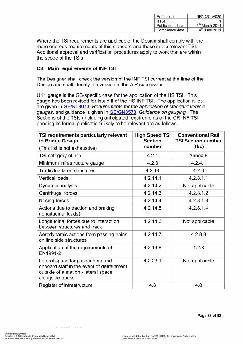
Reference NR/L3/CIV/020 Issue 1 Publication date 5th March 2011
Compliance date 4th June 2011
Page 88 of 92
Where the TSI requirements are applicable, the Design shall comply with the more onerous requirements of this standard and those in the relevant TSI. Additional approval and verification procedures apply to work that are within the scope of the TSIs.
C3 Main requirements of INF TSI
The Designer shall check the version of the INF TSI current at the time of the Design and shall identify the version in the AIP submission.
UK1 gauge is the GB-specific case for the application of the HS TSI. This gauge has been revised for Issue II of the HS INF TSI. The application rules are given in GE/RT8073: Requirements for the application of standard vehicle gauges, and guidance is given in GE/GN8573: Guidance on gauging. The Sections of the TSIs (including anticipated requirements of the CR INF TSI pending its formal publication) likely to be relevant are as follows.
TSI requirements particularly relevant to Bridge Design (This list is not exhaustive)
High Speed TSI Section number
Conventional Rail TSI Section number
(tbc)
TSI category of line 4.2.1 Annex E Minimum infrastructure gauge 4.2.3 4.2.4.1 Traffic loads on structures 4.2.14 4.2.8 Vertical loads 4.2.14.1 4.2.8.1.1 Dynamic analysis 4.2.14.2 Not applicable Centrifugal forces 4.2.14.3 4.2.8.1.2 Nosing forces 4.2.14.4 4.2.8.1.3 Actions due to traction and braking (longitudinal loads)
4.2.14.5 4.2.8.1.4
Longitudinal forces due to interaction between structures and track
4.2.14.6 Not applicable
Aerodynamic actions from passing trains on line side structures
4.2.14.7 4.2.8.3
Application of the requirements of EN1991-2
4.2.14.8 4.2.8
Lateral space for passengers and onboard staff in the event of detrainment outside of a station - lateral space alongside tracks
4.2.23.1 Not applicable
Register of infrastructure 4.8 4.8
Copyright Network Rail Provided by IHS Markit under license with Network Rail Licensee=United Kingdom-Coryton /3219500196, User=Sanjeevan, Poologanathan
Not for Resale, 06/20/2018 03:51:06 MDTNo reproduction or networking permitted without license from IHS
--``,````,`,`,``,,,,,,,,,``,,,-`-`,,`,,`,`,,`---

Reference NR/L3/CIV/020 Issue 1 Publication date 5th March 2011
Compliance date 4th June 2011
Page 89 of 92
Assessment of conformity with TSI and/or verification
6.2 6.2
Particular features of the British network 7.3.6 7.6.13
C4 Other TSI considerations
The TSI for conventional rail is likely to be issued shortly following the issue of this standard, and Designers shall check whether or not it has been published, and include the applicable design parameters in the AIP.
The following INF TSI aspects shall also be considered in the Design.
TSI aspect (This list is not exhaustive)
High Speed TSI Section number
Conventional Rail TSI Section
number (tbc) Essential (general and specific) requirements, and meeting those requirements, including:
Reliability and availability (including monitoring and maintenance) Safety Health (including materials hazardous to health) Environmental protection Technical compatibility
3.2 and 3.3 3 (check list)
Operational noise 3.2.2 4.2.11.2
Ground vibration 3.2.2 4.2.11.2
Prevention of unauthorised access 3.3.1 Not applicable
Copyright Network Rail Provided by IHS Markit under license with Network Rail Licensee=United Kingdom-Coryton /3219500196, User=Sanjeevan, Poologanathan
Not for Resale, 06/20/2018 03:51:06 MDTNo reproduction or networking permitted without license from IHS
--``,````,`,`,``,,,,,,,,,``,,,-`-`,,`,,`,`,,`---

Reference NR/L3/CIV/020 Issue 1 Publication date 5th March 2011
Compliance date 4th June 2011
Page 90 of 92
Appendix D Modification to GC/RT5212
This modification to GC/RT5212 shall not be implemented for a Bridge that is subject to high speed TSI requirements (see 9.2 and Appendix C), as on such routes the high speed requirements place a statutory requirement to comply with that standard.
Issue 1 of GC/RT5212 supersedes GE/RT8029: Management of clearances and gauging.
Appendix B of GE/RT8029 defined a ‘Structure gauge for areas close to the plane of the rail’, which included an area defined as being an ‘area for dwarf signals, bridge girders, and other lineside equipment (conductor rail equipment, such as hook switches, is also permitted to utilise this area)’. The area extended outwards from a point 240 mm + 318 mm = 558 mm from the nearest running edge, to a height of 110 mm above the plane of the rails.
In Appendix 1 of Issue 1 of GC/RT5212, the various areas included in the ‘Structure gauge for areas close to the plane of the rail’ were consolidated into an area designated as an ‘Area reserved for items intended to come in close proximity to trains (for example, conductor rails and AWS magnets)’. Bridge girders were therefore excluded from being placed in this area - as bridge girders are not ‘intended to come in close proximity to trains’ in the same way as conductor rails and AWS magnets. However it was not the intention to exclude girders from this area, as previously permitted by GE/RT8029: the exclusion was inadvertent - there are no safety grounds for the exclusion.
The Design shall, therefore, permit fixed infrastructure to be located in the ‘area for dwarf signals, bridge girders, and other lineside equipment’ - as previously identified in GE/RT8029. Until such time that GC/RT5212 is revised (to allow girders to be located in the area), details of girders (including their dimensions) located in the area shall be identified in the AIP submission, and a cross reference given to this Appendix.
GM/RT2149: Requirements for defining and maintaining the size of railway vehicles permits train builders to design a swept envelope that comes within 50 mm of the area being considered here, reducing to 25 mm ‘under worst case conditions, such as suspension failure’. Section G2 of GC/RT5212 therefore states: ‘When designing new infrastructure, allowance shall be made for construction tolerances to ensure these requirements [that structures do not intrude inside the structure gauge set out in Appendix 1] are met once the infrastructure has been built’. (In this context, ‘Infrastructure’ is defined as track and structures in combination.) Therefore, allowance has to be made for construction tolerances of both the structure and the adjacent track. Bridge girders occupying the area subject to this modification shall continue to meet this requirement.
Copyright Network Rail Provided by IHS Markit under license with Network Rail Licensee=United Kingdom-Coryton /3219500196, User=Sanjeevan, Poologanathan
Not for Resale, 06/20/2018 03:51:06 MDTNo reproduction or networking permitted without license from IHS
--``,````,`,`,``,,,,,,,,,``,,,-`-`,,`,,`,`,,`---
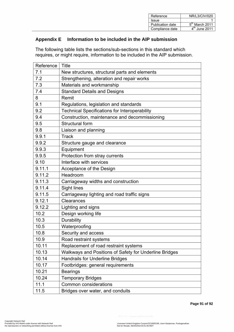
Reference NR/L3/CIV/020 Issue 1 Publication date 5th March 2011
Compliance date 4th June 2011
Page 91 of 92
Appendix E Information to be included in the AIP submission
The following table lists the sections/sub-sections in this standard which requires, or might require, information to be included in the AIP submission.
Reference Title 7.1 New structures, structural parts and elements 7.2 Strengthening, alteration and repair works 7.3 Materials and workmanship 7.4 Standard Details and Designs 8 Remit 9.1 Regulations, legislation and standards 9.2 Technical Specifications for Interoperability 9.4 Construction, maintenance and decommissioning 9.5 Structural form 9.8 Liaison and planning 9.9.1 Track 9.9.2 Structure gauge and clearance 9.9.3 Equipment 9.9.5 Protection from stray currents 9.10 Interface with services 9.11.1 Acceptance of the Design 9.11.2 Headroom 9.11.3 Carriageway widths and construction 9.11.4 Sight lines 9.11.5 Carriageway lighting and road traffic signs 9.12.1 Clearances 9.12.2 Lighting and signs 10.2 Design working life 10.3 Durability 10.5 Waterproofing 10.8 Security and access 10.9 Road restraint systems 10.11 Replacement of road restraint systems 10.13 Walkways and Positions of Safety for Underline Bridges 10.14 Handrails for Underline Bridges 10.17 Footbridges: general requirements 10.21 Bearings 10.24 Temporary Bridges 11.1 Common considerations 11.5 Bridges over water, and conduits
Copyright Network Rail Provided by IHS Markit under license with Network Rail Licensee=United Kingdom-Coryton /3219500196, User=Sanjeevan, Poologanathan
Not for Resale, 06/20/2018 03:51:06 MDTNo reproduction or networking permitted without license from IHS
--``,````,`,`,``,,,,,,,,,``,,,-`-`,,`,,`,`,,`---

Reference NR/L3/CIV/020 Issue 1 Publication date 5th March 2011
Compliance date 4th June 2011
Page 92 of 92
12.5 Fatigue assessment 13 Particular loading requirements for strengthening, alteration and
repair works for structures carrying rail traffic 14.2 Pedestrian, cycle and equestrian loading 14.3 Parapets, safety barriers and handrails 14.4 Accidental derailment loading 16.3 Uplift at bearings 17.5 Substructures affected by new construction 18.10.1 General design requirements C2 Application C3 Main requirements of INF TSI C4 Other TSI considerations D Modification to GC/RT5212
Copyright Network Rail Provided by IHS Markit under license with Network Rail Licensee=United Kingdom-Coryton /3219500196, User=Sanjeevan, Poologanathan
Not for Resale, 06/20/2018 03:51:06 MDTNo reproduction or networking permitted without license from IHS
--``,````,`,`,``,,,,,,,,,``,,,-`-`,,`,,`,`,,`---

25/05/2010 - Version 1
Standards Briefing Note
Ref: NR/L3/CIV/020 Issue: 1 Title: Design of Bridges Publication Date: 05/03/2011 Compliance Date: 04/06/2011 Standard Owner: Professional Head (Buildings and Civils) Non-Compliance rep (NRNC): Senior Policy Development Specialist, Ken Brady Further information contact: Ken Brady Tel: 020 7557 8367 Purpose: The purpose of the standard is to define the requirements for the structural Design of Bridges and Bridge-like structures
Scope: Ownership and management This standard is applicable to the Design of temporary and permanent Bridges and Bridge-like structures. Types of structure This standard is applicable to the structural Design of Bridges and to Bridge-like structures such as;
• Culverts, • subways, • structures that support buildings over operational railway lines, • cut and cover structures, • elevated vehicle forecourts and ramps, • avalanche shelters.
This standard is not applicable to the Design of; • Equipment support structures - such as gantries for signals or
overhead line electrification (OLE), • Earthworks (but see 17 for the design of earth retaining walls), • cable bridges, • pipe bridges (but see 10.20), • pipes, • buildings and other structures that are supported by a Bridge.
Extent of structures For the types of structure within its scope, this standard applies to all structural parts (such as decks and abutments) and elements (such as beams, columns and ballast plates) and permanent access facilities (such as walkways) that are integral with the structure. However, this standard is not applicable to the design of Longitudinal timbers - this is covered by NR/L2/TRK/038: Longitudinal timbers - design, installation and maintenance. Categories of work This standard applies to the Design of;
• repair works, • alterations, • strengthening works, • renewed/replaced structural elements, • renewed/replaced parts, • new structures.
This standard also applies to; • all stages where permanent works and temporary works are
taken into operational use in stages, see NR/L3/MTC/089: Asset Management Plan,
• temporary works provided for the execution of the structure. Types of rail traffic This standard is applicable to structures carrying conventional railway traffic at conventional speeds; that is;
• passenger rail traffic with a maximum permitted speed not exceeding 125 mph (200 km/h),
• freight traffic with a maximum axle weight of 25 tons and maximum permitted speed not exceeding 60 mph (100 km/h),
• freight traffic with a maximum axle weight of 22.5 tons and Copyright Network Rail Provided by IHS Markit under license with Network Rail Licensee=United Kingdom-Coryton /3219500196, User=Sanjeevan, Poologanathan
Not for Resale, 06/20/2018 03:51:06 MDTNo reproduction or networking permitted without license from IHS
--``,````,`,`,``,,,,,,,,,``,,,-`-`,,`,,`,`,,`---

25/05/2010 - Version 1
maximum permitted speed not exceeding 75 mph (120 km/h). Instruction and guidance on the Design of structures that are intended to carry rail traffic travelling in excess of these speeds can be sought from Network Rail’s Professional Head (Buildings and Civils).
What’s New/ What’s Changed and Why: This standard provides the basis for the design of Bridges and Bridge-like structures: the standard covers: 1 Design approach for new works, and for strengthening, alteration and repair works. 2 General design requirements, including regulations, legislation and standards; health and safety operational
requirements; construction, maintenance and decommissioning; environmental considerations; legal obligation and liability issues; liaison and planning; interfaces with the railway, services, highways and waterways.
3 Particular design requirements, including Technical Approval; design working life; durability; water management; waterproofing, protective coating systems, protection against derailment; security and access; road restraint systems; prevention of vehicle incursions; walkways, positions of safety and handrailing; and bearings.
4 Loading - general requirements and specific railway; highway and pedestrian loading requirements. 5 Deformation requirements. 6 Fatigue requirements. 7 Loading on substructures and foundations.
The standard provides direction and guidance on the application of the Structural Eurocodes and on meeting TSI requirements.
Affected documents: Reference
RT/CE/S/007 ISSUE 1
Impact
Withdrawn
Briefing requirements: Where Technical briefing (T) is required, the specific Post title is indicated. These posts have specific responsibilities within this standard and receive briefing as part of the Implementation Programme. For Awareness briefing (A) the Post title is not mandatory.
Please see http://ccms2.hiav.networkrail.co.uk/webtop/drl/objectId/09013b5b804504da for guidance.
Briefing (A-Awareness/ T-Technical)
Post Team
Function
A
Heads of Civils Asset Management, Route Structures Engineer, Route Building Engineers, Route Geotechnical Engineers, Principal Managed Station Engineer
Asset Management (B&C) Asset Management
A All post holders Technology teams Engineering (Buildings and Civils)
A Senior Project Engs, Prog Eng Managers, Senior Design Engs, Senior Project Engs, Principal Design Engs
Enhancements, B&C, Crossrail, Thameslink Investment Projects
‘Detailed Awareness Briefing’ to be provided as part of usual quarterly Awareness briefing of standards change. Then cascaded to members of the various teams.
*NOTE: Contractors are responsible for arranging and undertaking their own Technical and Awareness Briefings in accordance with their own processes and procedure
Copyright Network Rail Provided by IHS Markit under license with Network Rail Licensee=United Kingdom-Coryton /3219500196, User=Sanjeevan, Poologanathan
Not for Resale, 06/20/2018 03:51:06 MDTNo reproduction or networking permitted without license from IHS
--``,````,`,`,``,,,,,,,,,``,,,-`-`,,`,,`,`,,`---
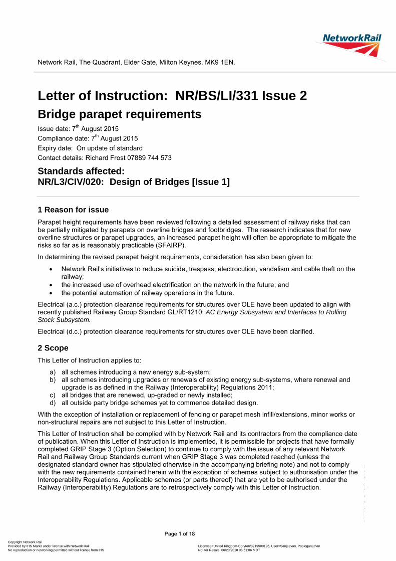
Network Rail, The Quadrant, Elder Gate, Milton Keynes. MK9 1EN.
Letter of Instruction: NR/BS/LI/331 Issue 2 Bridge parapet requirements Issue date: 7th August 2015 Compliance date: 7th August 2015 Expiry date: On update of standard Contact details: Richard Frost 07889 744 573
Standards affected: NR/L3/CIV/020: Design of Bridges [Issue 1]
1 Reason for issue Parapet height requirements have been reviewed following a detailed assessment of railway risks that can be partially mitigated by parapets on overline bridges and footbridges. The research indicates that for new overline structures or parapet upgrades, an increased parapet height will often be appropriate to mitigate the risks so far as is reasonably practicable (SFAIRP).
In determining the revised parapet height requirements, consideration has also been given to:
• Network Rail’s initiatives to reduce suicide, trespass, electrocution, vandalism and cable theft on the railway;
• the increased use of overhead electrification on the network in the future; and • the potential automation of railway operations in the future.
Electrical (a.c.) protection clearance requirements for structures over OLE have been updated to align with recently published Railway Group Standard GL/RT1210: AC Energy Subsystem and Interfaces to Rolling Stock Subsystem.
Electrical (d.c.) protection clearance requirements for structures over OLE have been clarified.
2 Scope This Letter of Instruction applies to:
a) all schemes introducing a new energy sub-system; b) all schemes introducing upgrades or renewals of existing energy sub-systems, where renewal and
upgrade is as defined in the Railway (Interoperability) Regulations 2011; c) all bridges that are renewed, up-graded or newly installed; d) all outside party bridge schemes yet to commence detailed design.
With the exception of installation or replacement of fencing or parapet mesh infill/extensions, minor works or non-structural repairs are not subject to this Letter of Instruction.
This Letter of Instruction shall be complied with by Network Rail and its contractors from the compliance date of publication. When this Letter of Instruction is implemented, it is permissible for projects that have formally completed GRIP Stage 3 (Option Selection) to continue to comply with the issue of any relevant Network Rail and Railway Group Standards current when GRIP Stage 3 was completed reached (unless the designated standard owner has stipulated otherwise in the accompanying briefing note) and not to comply with the new requirements contained herein with the exception of schemes subject to authorisation under the Interoperability Regulations. Applicable schemes (or parts thereof) that are yet to be authorised under the Railway (Interoperability) Regulations are to retrospectively comply with this Letter of Instruction.
Page 1 of 18 Copyright Network Rail Provided by IHS Markit under license with Network Rail Licensee=United Kingdom-Coryton /3219500196, User=Sanjeevan, Poologanathan
Not for Resale, 06/20/2018 03:51:06 MDTNo reproduction or networking permitted without license from IHS
--``,````,`,`,``,,,,,,,,,``,,,-`-`,,`,,`,`,,`---

Network Rail, The Quadrant, Elder Gate, Milton Keynes. MK9 1EN.
3 Changes Clause/subclause Change
Reference documentation
Replace section “Statutory Regulations” with the following:
Statutory Regulations
(The following should be read in conjunction with associated amendment regulations (not listed))
Health and Safety at Work Act 1974
The Construction (Design and Management) Regulations 2015 (S.I. No. 51)
The Electricity at Work Regulations 1989 (S.I. No. 635)
The Railway Safety (Miscellaneous Provision) Regulations 1997 (S.I. No. 553)
The Health and Safety (Safety Signs and Signals) Regulations 1996 (S.I. No. 341)
The Traffic Signs Regulations and General Directions 2002 (S.I. No. 3113)
The Building Regulations 2010 (SI No 2214)
Railway Interoperability Directive 2008/57/EC
The Railways (Interoperability) Regulations 2011 (SI No. 3066)
Technical Specifications for Interoperability (TSIs)
1299/2014/EU Infrastructure (INF TSI)
1300/2014/EU Persons with Reduced Mobility (PRM TSI)
1301/2014/EU Energy (ENE TSI)
1303/2014/EU Safety in Railway Tunnels (SRT TSI)
Remove GE/RT8025, GL/RT1253 (withdrawn) and BS EN 50122 entries and insert the following:
Railway Group Standards
GE/RT8025 Electrical protective provisions for electrified lines (part superseded by GL/RT1210)
GL/RT1210 AC Energy Subsystem and Interfaces to Rolling Stock Subsystem
GL/GN1610 Guidance on AC Energy Subsystem and Interfaces to Rolling Stock Subsystem
GM/RT1041 Warning Signs and Notices for Electrified Lines
British Standards
BS EN 50122 Railway applications - Fixed installations
Part 1: Protective provisions relating to electrical safety and earthing (2011)
Part 2: Protective provisions against the effects of stray currents caused by d.c. traction systems (2010)
Part 3: Mutual Interaction of a.c. and d.c. traction systems (2010)
Page 2 of 18 Copyright Network Rail Provided by IHS Markit under license with Network Rail Licensee=United Kingdom-Coryton /3219500196, User=Sanjeevan, Poologanathan
Not for Resale, 06/20/2018 03:51:06 MDTNo reproduction or networking permitted without license from IHS
--``,````,`,`,``,,,,,,,,,``,,,-`-`,,`,,`,`,,`---

Network Rail, The Quadrant, Elder Gate, Milton Keynes. MK9 1EN.
7.2 Strengthening, alteration and repair works
Add the following new paragraphs beneath paragraph 3:
Where existing structures span over new or upgraded OLE (as defined in 4.1.1.3 of GL/RT1210), parapets shall be upgraded to comply with the geometrical, electrical clearance and protection, and material requirements of this standard and associated Letter of Instruction (see 9.9.4, 10.9 and 10.10).
Furthermore, parapet and parapet height upgrades shall be considered as part of any significant structure strengthening works.
9.1 Regulations, legislation and standards
Replace paragraph 1 with the following:
Designers are obliged to meet the requirements of; • Relevant legislation, that includes (inter alia):
- The Railways (Interoperability) Regulations 2011 - Health and Safety at Work Act (1974) - The Construction (Design and Management) Regulations 2015 - The Electricity at Work Regulations 1989 - The Railway Safety (Miscellaneous Provision) Regulations 1997 - The Health and Safety (Safety Signs and Signals) Regulations 1996 - The Traffic Signs Regulations and General Directions 2002 - The Building Regulations 2010
• Railway Group Standards • Network Rail standards • Other standards (generally European ones, but National ones where
these are not available) and product specifications etc.
9.7 Legal obligation and commercial liability issues
Replace paragraph 3 with the following:
Unless the task has been delegated to the Designer, legal obligation and commercial liability issues shall be addressed by Network Rail’s Head of Liability Negotiation; such issues include:
• liabilities; • easements and wayleaves; • load-carrying obligations; • requirements for headroom, carriageway widths, electrical protection
provisions etc.; • agreements regarding the maintenance, replacement and renewal of
infrastructure and services.
9.8 Liaison and planning
Replace paragraph 8 with the following:
Network Rail shall, through consultation with the relevant roads/highway authority, private owner and users, agree the requirements for (for example) lateral and vertical clearances, carriageway widths, sight lines and traffic signs (9.11), and electrical protective provisions (9.9.4). Such consultations shall take into account existing agreements and legal obligations. Similarly, Network Rail shall consult the relevant authorities, private owner and users, to agree the requirements for waterways for (for example) clearances, lighting and signs (9.12), taking account of existing agreements and legal obligations.
9.9.4 Electrical protection, earthing and bonding
Replace sub-section 9.9.4 with the following text:
The design of a structure shall minimise the risk of electric shock so far as is reasonably practicable (SFAIRP) and is obliged to meet the requirements of The Electricity at Work Regulations (notably regulations 4(1) and 7).
Page 3 of 18 Copyright Network Rail Provided by IHS Markit under license with Network Rail Licensee=United Kingdom-Coryton /3219500196, User=Sanjeevan, Poologanathan
Not for Resale, 06/20/2018 03:51:06 MDTNo reproduction or networking permitted without license from IHS
--``,````,`,`,``,,,,,,,,,``,,,-`-`,,`,,`,`,,`---

Network Rail, The Quadrant, Elder Gate, Milton Keynes. MK9 1EN.
The design of a structure carrying or passing over a.c. electrified lines shall comply with the electrical and mechanical requirements of GL/RT1210: AC Energy Subsystem and Interfaces to Rolling Stock Subsystem (see also 10.10).
The design of a structure carrying or passing over d.c. electrified lines is obliged to comply with the electrical protection requirements of GE/RT8025: Electrical protective provisions for electrified lines until publication of GL/RT1212: DC Energy Subsystem and Interfaces to Rolling Stock Subsystem which the design is then obliged to complied with.
Passive provision for potential future a.c. electrification of the railway shall be provided for new structures that carry or span over non-electrified or d.c. electrified lines unless located on a line where planned electrification is not reasonably foreseeable. The Designer shall agree with Network Rail, the extent of passive provision to be provided prior to AiP submission.
Bonding that is required exclusively for signalling purposes is outside the scope of this standard.
The design of earthing and bonding systems for a structure (including its metallic elements and services) is obliged to meet the requirements of:
• BS EN 50122-1: Railway applications - Fixed installations. Protective provisions relating to electrical safety and earthing,
• BS EN 50122-2: Railway applications. Fixed installations. Protective provisions against the effects of stray currents caused by d.c. traction systems,
• BS EN 50122-3: Railway applications. Fixed installations. Electrical safety, earthing and the return circuit. Mutual Interaction of a.c. and d.c. traction systems, and
• NR/SP/ELP/21085: Design of earthing and bonding systems for 25 kV a.c. electrified lines.
Two of the principal requirements of NR/SP/ELP/21085 are:
1 Exposed metal elements and metal services shall be bonded to the traction return rail or earth wire. Concrete reinforcement (including pre-stressing anchorages) shall be bonded only if it is accessible or electrically connected to accessible metalwork.
2 The interconnections and bonding shall, so far as practicable, be arranged such that traction current flow through the bridge, structural metalwork, and services is avoided.
Note that NR/SP/ELP/21085 only applies to a.c. overhead electrification systems; steel structures should not be bonded to the return rail on d.c. electrified routes.
Where railway equipment, railway signal structures, or other equipment support structures attached to the structure are required to be bonded to the traction return rail, the design of the interface between them shall be such that all the metallic elements form a continuous electrical whole.
Where metal fences are to be attached to a structure, the electrical protection of the structure and fences (including gates) shall be considered as a whole; consideration shall be given to the use of non-conducting fencing.
Conductive trays or ladders that support electrical cables, and which are to be attached to a structure, shall be earthed to the structure.
Consideration shall be given in design to maximising the use of metalwork and
Page 4 of 18 Copyright Network Rail Provided by IHS Markit under license with Network Rail Licensee=United Kingdom-Coryton /3219500196, User=Sanjeevan, Poologanathan
Not for Resale, 06/20/2018 03:51:06 MDTNo reproduction or networking permitted without license from IHS
--``,````,`,`,``,,,,,,,,,``,,,-`-`,,`,,`,`,,`---

Network Rail, The Quadrant, Elder Gate, Milton Keynes. MK9 1EN.
the reinforcement in substructures for earthing.
Where required by Network Rail, the design shall include provision for (a) fitting bonding/earthing studs to the structure, and (b) installing remote earth test-points.
Where a structure spans an overhead electrified railway, the design shall consider the waterproofing of the structure and managing run-off to prevent damage by water draining on to, or in the proximity of, the overhead electrification, causing flash over.
Where a new Outside Party structure spans an overhead electrified railway, or existing Outside Party structure spans a new or upgraded overhead electrification system, electrical protection (clearances and earthing and bonding system) shall be in accordance with the principles of GL/RT1210 and NR/SP/ELP/21085 and be agreed with the Outside Party.
The Designer shall strive to produce an effective and economic earthing and bonding system that takes due account of the traction power supply system, overhead line equipment, and other electrical components and equipment at the site. The design documentation for the system shall meet the requirements of NR/SP/ELP/21085 and is subject to acceptance by Network Rail.
9.9.5 Protection from stray currents
Replace the first paragraph with the following text:
Where third rail d.c. electrification is present, the design shall consider the risk of corrosion generated by stray currents. The Designer shall agree with Network Rail, prior to the AiP submission, any stray current mitigations that are to be incorporated into the design.
10.8 Security and access
Replace subsection 10.8 with the following text:
Jumping or falling off, trespass via, or objects thrown over bridge parapets, account for the majority of structure related risks to the railway.
Bridge parapets and fencing in the vicinity of a structure shall be designed such that unauthorised access to the railway infrastructure is prevented so far as is reasonably practicable, and are obliged to be compliant with The Railway Safety (Miscellaneous Provisions) Regulations 1997 (Regulation 3)).
The design of the layout of fencing in the vicinity of a structure shall be such that the fences and structure form an adequate and continuous barrier against trespass onto the railway. The requirements for providing security to the railway are given in NR/L2/TRK/5100: Management of Fencing and Other Boundary Measures.
Consideration shall be given to providing (a) access gates in fences, and (b) access steps down earthworks, near to a structure to facilitate its examination and maintenance.
To reduce the risk of unauthorised access to the railway, people shall be deterred from climbing the parapets on an overline bridge or footbridge (for example, by increasing the height of parapets, attaching mesh screens, installing anti-vandalism cages or anti-trespass spikes) and accessing the outer faces of the overline structure.
Details of the access arrangements (provision and prevention) shall be identified in the AiP submission.
10.9 Road restraint systems
Replace paragraphs 12 to 14 with the following text:
Parapets are not required to extend beyond the length of the abutment or
Page 5 of 18 Copyright Network Rail Provided by IHS Markit under license with Network Rail Licensee=United Kingdom-Coryton /3219500196, User=Sanjeevan, Poologanathan
Not for Resale, 06/20/2018 03:51:06 MDTNo reproduction or networking permitted without license from IHS
--``,````,`,`,``,,,,,,,,,``,,,-`-`,,`,,`,`,,`---

Network Rail, The Quadrant, Elder Gate, Milton Keynes. MK9 1EN.
retaining walls.
The height of new/renewed vehicle parapets above adjoining paved surface over the railway shall not be less than the following: 1800mm for bridges over an automatic/driverless railway 1800mm for bridges frequently used by equestrian traffic 1800mm for bridges where there is a high risk of trespass or vandalism
or suicide 1800mm for parts of bridges over OLE where electrification ‘protection
by safety clearance’ requirements are not achieved (see 10.10) *1800mm for other overline bridges and upgraded parapets that span over
the railway where pedestrians, animals, pedal cycles and vehicles drawn by animals are not excluded by Order (* see note 1 below)
1500mm for other bridges (e.g. motorway bridges and bridges not over the railway where the above higher risk categories don’t apply)
Note 1. For new or renewed overline bridges where pedestrians are not excluded by Statutory Order, the 1800mm minimum height requirement may be reduced to 1500mm where either the structure is sited at a low-risk location, or the provision of 1800mm (min) high parapets over the railway is not practicable or appropriate (e.g. due to geometrical, technical, safety or planning limitations), provided that (a) the height reduction has been justified by appropriate site-specific risk assessment, and (b) the justification is included with supporting evidence within Form 001 and Form 002 design submissions and is accepted by the Network Rail Asset Manager (Civils) and (for reduced height parapets over OLE) Network Rail Asset Manager (E&P).
For the purposes of the above reduced requirement, low-risk locations are typically considered to have the following attributes:
- Low risk of route crime (e.g. away from built up areas, schools, other frequently used pedestrian routes, train depots and other crime-susceptible installations); and
- Low risk of suicide (footway less than 10m above the tracks); and - No/low risk of electrocution (e.g. no existing or planned OLE or
where ‘protection by safety clearance’ [to OLE] is provided).
Additional parapet height requirements may apply where bridges cross over existing, new or planned overhead electrified railway lines or routes (see 10.10), or where additional security measures are required (see 10.8).
Where pedestrians are not excluded by Statutory Order, new or renewed vehicle parapets over the railway shall have an inner face which is smooth, non-perforate over their full height, and without hand or footholds.
New or renewed vehicle parapets over the railway shall have an inner face which is smooth, non-perforate over their full height, and without hand or footholds.
Vehicle parapets over the railway shall be provided with steeple copings, or similar anti-climbing feature.
The following parapet coping profiles are recommended:
1 Where the width of the parapet top is greater than 100 mm but less than about 250 mm (as would be the case with reinforced concrete construction), one of the profiles given in BS 6779-2: Highway parapets
Page 6 of 18 Copyright Network Rail Provided by IHS Markit under license with Network Rail Licensee=United Kingdom-Coryton /3219500196, User=Sanjeevan, Poologanathan
Not for Resale, 06/20/2018 03:51:06 MDTNo reproduction or networking permitted without license from IHS
--``,````,`,`,``,,,,,,,,,``,,,-`-`,,`,,`,`,,`---

Network Rail, The Quadrant, Elder Gate, Milton Keynes. MK9 1EN.
for bridges and other structures. Part 2. Specification for vehicle containment parapets of concrete construction.
2 Where the width of the top of the parapet substantially exceeds 250 mm (as would be the case with brick sandwich construction),
• a slope of 35 ± 1º to the horizontal with no overhang on the highway side,
• a slope of 60 ± 1º to the horizontal on the railway side (with an overhang if appropriate),
• hence an apex angle of 85 ± 2º - there may be an apex chamfer of up to 30 mm wide.
3 An equilateral triangle - there may be an apex chamfer of up to 30 mm wide.
10.10 Parapets over OLE
Replace contents of subsection with the following:
The following requirements apply to structures over OLE or lines/routes subject to planned overhead electrification. Planned electrification of railway lines are referenced in either the:
• Network Route Utilisation Strategy; or • Network and Route Specifications
For an existing structure over an existing a.c. energy subsystem, compliance with 10.10.1 and 10.10.2 is not required until either:
• The a.c. energy subsystem is modified or renewed as a whole; or • Any major component of the a.c. energy subsystem is replaced.
10.10.1 Protective provisions against direct contact
Protective provisions against direct contact with exposed live parts of the overhead line equipment are obliged to comply with BS EN 50122-1, Section 2.2 of GL/RT1210 and the requirements below.
The protective provisions against direct contact shall be by safety clearances or, where the safety clearances are not achievable, by obstacles. The maximum reasonably practicable value of electrical clearance shall be provided.
The minimum electrical clearances specified in this sub-section are minimum clearances under all operating conditions. Accordingly an appropriate allowance for temperature and dynamic movements shall be added to the specified minimum clearance values.
Return conductors (or feeder conductors for auto-transformer OLE system) shall be treated as live parts unless adequately insulated. Where protection by safety clearance or protection by obstacles cannot be achieved for these elements, the return/feeder cables shall be insulated and shielded (as appropriate) in accordance with GL/RT1210 clauses 2.2.2.5 and 2.2.3.3.
For protection by safety clearance, the minimum clearances shall be the public area dimensions set out in EN 50122-1:2011+A1:2011 clause 5.2.1, Figure 3 (for Low Voltage (LV) systems), and Figure 4 (for High Voltage (HV) systems).
Where protection of exposed live parts by safety clearances is not achievable or appropriate (e.g. due to disproportionate costs), electrical protection by an obstacle shall be provided and of a construction to prevent unintentional direct contact with a live part; requirements as follows.
Page 7 of 18 Copyright Network Rail Provided by IHS Markit under license with Network Rail Licensee=United Kingdom-Coryton /3219500196, User=Sanjeevan, Poologanathan
Not for Resale, 06/20/2018 03:51:06 MDTNo reproduction or networking permitted without license from IHS
--``,````,`,`,``,,,,,,,,,``,,,-`-`,,`,,`,`,,`---

Network Rail, The Quadrant, Elder Gate, Milton Keynes. MK9 1EN.
a) The obstacle (parapet and any extension) shall be of construction and height to meet the minimum requirements detailed in Figures 10.10.1 to 10.10.3 and additional requirements below.
(Different requirements apply for public and restricted areas and for HV and LV equipment. ‘Restricted areas’ are areas of Network Rail infrastructure where access is controlled for authorised persons only. Other areas (including roads/motorways where pedestrians are prohibited by Order) are deemed ‘public areas’).
b) Obstacles in ‘public areas’ shall be designed so that is it difficult to climb, stand or to walk on. An increased obstacle height (above 1.8m) shall be considered in areas prone to regular trespass or vandalism.
c) Obstacles shall be fixed reliably and with the use of tamper proof fixings; they shall only be removable with tools. Obstacles shall be secured so that the distance to the live parts is maintained.
d) The obstacle shall have no gap to the standing surface.
e) Where mesh extensions or infill is specified, mesh shall be in accordance with Chapter 8 of BS 6779-1. Mesh constructions of plastic coated metal shall not be utilised.
f) Where non-conductive obstacles are chosen within the overhead contact line zone and current collector zone (as defined in section 3.2 of GL/RT1210):
1. they shall be of imperforate design with materials selected so that they will not become conductive as a result of the likely effects of moisture, ultra-violet radiation, chemical attack or other environmental damage, nor of contact with live parts; and
2. additional protection shall be provided by way of an earthed frame when obstacles are located within 0.60m of exposed live parts.
Further guidance is provided in Appendix F.
10.10.2 Protective provisions against indirect contact (touch voltages)
Protection against electric shock is obliged to be achieved by compliance with the touch voltage requirements set out in BS EN 50122-1:2011+A1:2011 clauses 6.1, 6.2, 6.3, 9.1 and 9.2 (see also 9.9.4).
10.10.3 Warning signs
Electrocution warning signs shall be installed on the inside face of parapets over or adjacent to exposed live OLE when a risk of electric shock from OLE from the bridge has been introduced or increased and the residual risk is not insignificant.
Examples where electricity warning signs would be envisaged include:
• New or existing bridges over newly electrified lines where electrical protection to OLE is provided ‘by obstacle’ rather than ‘by safety clearance’.
• Any new bridge or bridge renewal where electrical protection to OLE is provided ‘by obstacle’ rather than ‘by safety clearance’.
When required, signs shall be installed at each end of the hazard zone, with
Page 8 of 18 Copyright Network Rail Provided by IHS Markit under license with Network Rail Licensee=United Kingdom-Coryton /3219500196, User=Sanjeevan, Poologanathan
Not for Resale, 06/20/2018 03:51:06 MDTNo reproduction or networking permitted without license from IHS
--``,````,`,`,``,,,,,,,,,``,,,-`-`,,`,,`,`,,`---

Network Rail, The Quadrant, Elder Gate, Milton Keynes. MK9 1EN.
intermediate signs where appropriate (e.g. for bridges spanning numerous overhead electrified lines).
Electrocution warning signs are obliged to be in accordance with BS EN ISO 7010 (Type W501.BS) and designed in accordance with BS ISO 3864-1. The hazard triangle shall be accompanied by the supplementary text ‘Danger - Live wires below’ as shown in Figure 10.10.4.
Figure 10.10.4 Electrocution warning sign
Danger Live wires below
Page 9 of 18 Copyright Network Rail Provided by IHS Markit under license with Network Rail Licensee=United Kingdom-Coryton /3219500196, User=Sanjeevan, Poologanathan
Not for Resale, 06/20/2018 03:51:06 MDTNo reproduction or networking permitted without license from IHS
--``,````,`,`,``,,,,,,,,,``,,,-`-`,,`,,`,`,,`---

Network Rail, The Quadrant, Elder Gate, Milton Keynes. MK9 1EN.
Protection by obstacle envelope
(ho ≥ 1.50m,ho < 1.80m)
h o h o
Scenario 1Solid or imperforate
parapet 1.50m - 1.80m)
Scenario 2Solid or imperforate
parapet ≥ 1.80m
1.50 1.
00 #
Protection by obstacle envelope(ho ≥ 1.80m)
Protection by clearance envelope for imperforate deck (only)
0.503.00
2.25
d R 2.25
0.50
0.50
Protection by clearance envelope (all decks)
3.50
0.50
0.600.60
R 3.50 1.00
EN 50122-1:2011 cl 5.2.1 Note 2 – Alternative protection by clearance envelope where (imperforate) decks provide protectionProtection by obstacle envelope (ho ≥ 1.80m with imperforate deck)
is the minimum permitted clearance in air between obstacle and live parts in accordance with GL/RT1210 cl. 2.2.3.2dIs the height of the solid section of parapeths
Is the overall height of the parapet (including any mesh extension)ho
dimension may be reduced by the same extent as the height hs exceeds the value of 1.80m#
EN 50122-1:2011 Figure 4 – Protection by clearance envelope
Perforated obstacle (deck or parapet)
Perforate or imperforate obstacle (deck or parapet)
Imperforate obstacle (deck or parapet)
Key
a) Public areas
b) Restricted areas
R 3.50
3.50
Protection by obstacle envelope
(ho ≥ 1.80m)
h o
h s ≥
1.2
5
1.50 + d
1.50
1.50
#
0.50
0.50
h s =
ho
1.50
Protection by clearance envelope (all decks)
Protection by obstacle envelope(ho ≥ 1.80m)
Scenario 1Solid parapet with
mesh extension
Scenario 2Full height solid
parapet
3.00
Protection by clearance envelope for imperforate deck (only)
2.25
d
0.60
R 2.25
0.60
0.50
0.50
Protection by clearance envelope (all decks)
Figure 10.10.1 Electrification clearances and parapet requirements for High Voltage systems
Page 10 of 18 Copyright Network Rail Provided by IHS Markit under license with Network Rail Licensee=United Kingdom-Coryton /3219500196, User=Sanjeevan, Poologanathan
Not for Resale, 06/20/2018 03:51:06 MDTNo reproduction or networking permitted without license from IHS
--``,````,`,`,``,,,,,,,,,``,,,-`-`,,`,,`,`,,`---

Network Rail, The Quadrant, Elder Gate, Milton Keynes. MK9 1EN.
EN 50122-1:2011 cl 5.2.1 Note 2 – Alternative protection by clearance envelope where (imperforate) decks provide protectionProtection by obstacle envelope (ho ≥ 1.80m with imperforate deck)
is the minimum permitted clearance in air between obstacle and live parts in accordance with GL/RT1210 cl. 2.2.3.2dIs the height of the solid section of parapeths
Is the overall height of the parapet (including any mesh extension)ho
dimension may be reduced by the same extent as the height hs exceeds the value of 1.80m#
EN 50122-1:2011 Figure 4 – Protection by clearance envelope
Perforated obstacle (deck or parapet)
Perforate or imperforate obstacle (deck or parapet)
Imperforate obstacle (deck or parapet)
Key
a) Public areas
b) Restricted areas
R 3.00
3.00
Protection by obstacle envelope
(ho ≥ 1.80m)
h o
h s ≥
1.2
5
1.50
1.50
#
0.50
0.50
h s =
ho
Protection by obstacle envelope(ho ≥ 1.80m)
Scenario 1Solid parapet with
mesh extension
Scenario 2Full height solid
parapet
2.50
Protection by clearance envelope for imperforate deck (only)
1.45
d 0.60R 1.45
0.60
0.50
0.50
Protection by clearance envelope (all decks)
1.45 1.45
Protection by obstacle envelope
(ho ≥ 1.50m,ho < 1.80m)
h o h o
Scenario 1Solid or imperforate
parapet 1.50m - 1.80m)
Scenario 2Solid or imperforate
parapet ≥ 1.80m
1.50 1.
00 #
Protection by obstacle envelope(ho ≥ 1.80m)
0.50
2.50
1.45
d
0.50
0.50 0.50
1.00R 3.00
0.600.60R 1.45
1.45
3.00
Protection by clearance envelope for imperforate deck (only)Protection by clearance
envelope (all decks)
Figure 10.10.2 Electrification clearances and parapet requirements for Low Voltage systems
Page 11 of 18 Copyright Network Rail Provided by IHS Markit under license with Network Rail Licensee=United Kingdom-Coryton /3219500196, User=Sanjeevan, Poologanathan
Not for Resale, 06/20/2018 03:51:06 MDTNo reproduction or networking permitted without license from IHS
--``,````,`,`,``,,,,,,,,,``,,,-`-`,,`,,`,`,,`---

Network Rail, The Quadrant, Elder Gate, Milton Keynes. MK9 1EN.
≥ 1.
80
≥ d
a) New or existing 1.8m high parapet
Parapet
Bridge deck
c
a b
≥ e
b) Existing 1.25m-1.8m Parapet (or new 1.5m-1.8m Parapet where permitted) – Protection by Clearance
Parapet
Bridge deck
c
a b
< 1.
80≥
1.25
c) Existing 1.25m-1.8m Parapet – Protection by Obstacle – Retrofit with vertical extension
Parapet
Bridge deck
a b
≥ 1.
80
fg
≥2.2
5
minimumnormal Imperforate (or mesh screen to BS 6779-1)
Track centreline
Parapet extensions
≥ 1.
80<
1.80
c
≥ 1.
80
Parapet extension (perforate or imperforate)
Key
Contact wire (or nearest live part)Line feeder, bare feeder, auto-transformer feeder or return conductor (or nearest live part)Standing surface (public areas including motorways)Minimum permitted clearance in air between obstacle and live parts in accordance with GL/RT1210 cl. 2.2.3.2‘Safety by clearance’ dimension to exposed live parts:- for imperforate decks, 2.25m for HV, 1.45m for LV, - for perforated decks, 3.00m for HV, 2.50m for LVMinimum 3.0m from track centreline to end of obstacleMinimum 1.4m where exposed conductors are being used for traction power supply (e.g. auto-transformer feeder wire) or 0.5m (minimum) where they are not.
All specified dimensions to live parts are minimum clearances under all operating conditions, i.e. temperature and dynamic movements (of both bridge and conductor) shall also be added.Inclined parapet extensions shall not extend beyond the rear (railway) face of the parapet by more than 100mm.BS6779-1 maximum aperture size for mesh screens is 25mm x 25mm for mesh, or 45mm x 20mm for expanded metal screens
abcde
fg
Notes
≥ d
< e
Figure 10.10.3 Parapets over OLE in public areas
Page 12 of 18 Copyright Network Rail Provided by IHS Markit under license with Network Rail Licensee=United Kingdom-Coryton /3219500196, User=Sanjeevan, Poologanathan
Not for Resale, 06/20/2018 03:51:06 MDTNo reproduction or networking permitted without license from IHS
--``,````,`,`,``,,,,,,,,,``,,,-`-`,,`,,`,`,,`---
Network Rail, The Quadrant, Elder Gate, Milton Keynes. MK9 1EN.
10.11 Replacement of road restraint systems
Add the following paragraph to the end of sub-section
Where existing vehicle or pedestrian parapets on an overline bridge are to be replaced, reconstructed or strengthened, they shall be upgraded to meet the parapet height and electrical protection requirements detailed in 9.9.4, 10.8, 10.9 and 10.10, where this can be achieved without unreasonable cost and without adversely affecting highway safety. The potential impact of increased parapet height on road driver sightlines shall be verified against TD9/93 requirements.
10.14 Handrails for Underline Bridges
Replace paragraph 5 with the following:
Where either an intersection bridge crosses a railway with OLE, or an underline bridge crosses a road/route with OLE (e.g. tram), the handrails shall (a) be 1.5 m high, (b) be infilled for at least 3 m on either side of the OLE, and (c) comply with the requirements of 10.10.
10.17 Footbridges: general requirements
Replace paragraph 7 with the following:
Except where the cladding or enclosure provides equivalent protection, pedestrian parapets shall be provided on Footbridges in accordance with TD 19/06 and the following additional or modified requirements.
The height of new/renewed footbridge parapets above adjoining footway shall not be less than the following:
*1800mm for overline footbridges or any footbridge where there is a high risk of trespass or vandalism or suicide (or 1500mm parapet with attached solid or mesh screen to provide 1800mm (minimum) overall height) (* see note 1 below)
1500mm for other Footbridges
Note 1. The 1800mm minimum height requirement may be reduced to 1500mm where either the structure is sited at a low-risk location, or the provision of 1800mm (min) high parapets is not practicable or appropriate (e.g. due to geometrical, technical, safety or planning limitations), provided that (a) the height reduction has been justified by appropriate site-specific risk assessment, and (b) the justification is included with supporting evidence within Form 001 and Form 002 design submissions and is accepted by the Network Rail Asset Manager (Civils) and (for reduced height parapets over OLE) Network Rail Asset Manager (E&P).
For the purposes of the above reduced requirement, low-risk locations are typically considered to have the following attributes:
- Low risk of route crime (e.g. within controlled areas within stations or away from built up areas, schools, other frequently used pedestrian routes, train depots and other crime-susceptible installations), and
- Low risk of suicide (footway less than 10m above the tracks), and - No/low risk of electrocution (e.g. no existing or planned OLE or
where ‘protection by safety clearance’ [to OLE] is provided).
Additional parapet height requirements may apply where additional security measures are required (see 10.8).
Page 13 of 18 Copyright Network Rail Provided by IHS Markit under license with Network Rail Licensee=United Kingdom-Coryton /3219500196, User=Sanjeevan, Poologanathan
Not for Resale, 06/20/2018 03:51:06 MDTNo reproduction or networking permitted without license from IHS
--``,````,`,`,``,,,,,,,,,``,,,-`-`,,`,,`,`,,`---

Network Rail, The Quadrant, Elder Gate, Milton Keynes. MK9 1EN.
Where footbridges (and their associated access steps or ramps) span over or are adjacent to existing, new or modified overhead electrified lines, the additional requirements of 9.9.4 and 10.10 shall also apply.
The use of mesh (to BS 7818) may be used for screens above 1500mm above the adjacent footway where increased passenger or public visibility is appropriate.
Appendix E Information to be included in the AIP submission
Add the following sections/sub-sections to the table:
Reference Title
9.9.4 Electrical protection, earthing and bonding
10.10 Parapets over OLE
Appendix F OLE and Parapet Height Decision Flowcharts (Informative Guidance)
Add the following figures to new Appendix F:
Page 14 of 18 Copyright Network Rail Provided by IHS Markit under license with Network Rail Licensee=United Kingdom-Coryton /3219500196, User=Sanjeevan, Poologanathan
Not for Resale, 06/20/2018 03:51:06 MDTNo reproduction or networking permitted without license from IHS
--``,````,`,`,``,,,,,,,,,``,,,-`-`,,`,,`,`,,`---

Network Rail, The Quadrant, Elder Gate, Milton Keynes. MK9 1EN.
Figure F1: Parapet requirements for new structures over OLE (Public areas)
Notes:
Parapet heights greater than 1.8m may be required where OLE is beside the parapet (e.g. platform stairs) (see 10.10.1). * 2.25m refers to minimum dimension for imperforate decks over HV OLE. For minimum dimensions for LV OLE or for perforate decks over HV OLE, refer to Figures 10.10.1 to 10.10.3.
NEW STRUCTURE
Is footway to OLE vertical
clearance ≥ 2.25m*
practicable?
Low risk environ-
ment
Parapet height Min parapet height = 1.80m (or where increased visibility is appropriate, 1.50m with glazed or mesh screen above to provide overall obstacle height of at least 1.8m) Minimum extent: Between railway boundaries
No
Parapet height: Min parapet height = 1.50m Minimum extent: Between railway boundaries
Yes
Protection by Safety Clearance
Design for ≥ 2.25m* clearance to OLE
Yes
Parapet height Min parapet height = 1.80m (or where increased visibility is appropriate, 1.50m with glazed or mesh screen above to provide overall obstacle height of at least 1.8m) Minimum extent: Between railway boundaries
Site specific risk assessment
Protection by Obstacle
Design to consider options for maximising
clearance to OLE
No
Page 15 of 18 Copyright Network Rail Provided by IHS Markit under license with Network Rail Licensee=United Kingdom-Coryton /3219500196, User=Sanjeevan, Poologanathan
Not for Resale, 06/20/2018 03:51:06 MDTNo reproduction or networking permitted without license from IHS
--``,````,`,`,``,,,,,,,,,``,,,-`-`,,`,,`,`,,`---
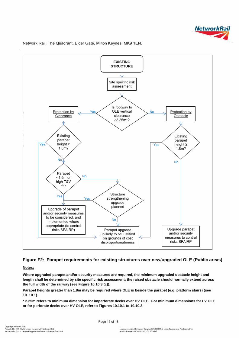
Network Rail, The Quadrant, Elder Gate, Milton Keynes. MK9 1EN.
Figure F2: Parapet requirements for existing structures over new/upgraded OLE (Public areas) Notes:
Where upgraded parapet and/or security measures are required, the minimum upgraded obstacle height and length shall be determined by site specific risk assessment; the raised obstacle should normally extend across the full width of the railway (see Figure 10.10.3 (c)). Parapet heights greater than 1.8m may be required where OLE is beside the parapet (e.g. platform stairs) (see 10. 10.1). * 2.25m refers to minimum dimension for imperforate decks over HV OLE. For minimum dimensions for LV OLE or for perforate decks over HV OLE, refer to Figures 10.10.1 to 10.10.3.
EXISTING STRUCTURE
Is footway to OLE vertical clearance ≥2.25m*?
Existing parapet height ≥ 1.8m?
No
Parapet upgrade unlikely to be justified
on grounds of cost disproportionateness
Yes
Protection by Clearance
Yes
Site specific risk assessment
Protection by Obstacle
No
Parapet <1.5m or high T&V
risk
Structure strengthening
upgrade planned
Upgrade parapet and/or security
measures to control risks SFAIRP
Upgrade of parapet and/or security measures
to be considered, and implemented where
appropriate (to control risks SFAIRP)
Existing parapet height ≥ 1.8m?
Yes
No
Yes
No
No
Yes
Page 16 of 18 Copyright Network Rail Provided by IHS Markit under license with Network Rail Licensee=United Kingdom-Coryton /3219500196, User=Sanjeevan, Poologanathan
Not for Resale, 06/20/2018 03:51:06 MDTNo reproduction or networking permitted without license from IHS
--``,````,`,`,``,,,,,,,,,``,,,-`-`,,`,,`,`,,`---

Copyright N
etwork R
ail P
rovided by IHS
Markit under license w
ith Netw
ork Rail
Licensee=U
nited Kingdom
-Coryton /3219500196, U
ser=S
anjeevan, Poologanathan
Not for R
esale, 06/20/2018 03:51:06 MD
TN
o reproduction or networking perm
itted without license from
IHS
--``,````,`,`,``,,,,,,,,,``,,,-`-`,,`,,`,`,,`---

Network Rail, The Quadrant, Elder Gate, Milton Keynes. MK9 1EN.
4 Recipients
Name Post
Rubina Greenwood Head of Buildings
Richard Stainton Head of Contact Systems
Ben Wilkinson David Castlo
Principal Engineer (Buildings and Civils)
Andrew Anderson, Mark Norman, Neil Jones, Michael Smith, Mark Huband Route Asset Manager (Civils - Structures)
Anthony Dewar, Nick Tedstone, Andy Cross Route Asset Manager (Civils)
Terry Shorten, Simon Gyde, Adam Checkley, James Walsh, Philippa Britton, Ian Grimes, Alan Bell, Katui Klutse
Route Asset Manager (Buildings)
Daniel Aisthorpe, Graeme Beale, Mark Davies, Cliff Elsey, Adrian Murray, Peter Smith-Jaynes, Carl Hunt, Nick Travis, Nigel Wheeler, Phil Stanley, Dean Chauke, Colin Lamb.
Route Asset Manager (E&P)
Andy Lundberg, Matthew Spence, Paul Buckley, Jane Austin, Rupert Randhawa, Huw James, Darren Nock, Martin Sigrist
Head of Engineering (IP)
Andrew Duffin, Graeme Tandy, Karl Budge, Nick Spall, Richard Walker, Stewart Macpherson, Ian Quick, Robert Williams, Robert Cairns, Simon Morgan, Steven Walters, Francis McGarry,
Route Delivery Director (IP)
Roger Querns, Bill Henry, Chris Montgomery, Dominic Baldwin, Saleem Mohammad, Matthew Steele, Paul Byrne, Paul Bates, Laurence Whitbourn
Project/Programme Director
Steve Brame Principal Engineer System Design
Mark Burton, Jonathan Wright, Tom Griffiths Programme Engineering Manager
5 Details of briefing or cascade communication process Briefings will be undertaken by the Professional Head or his representative, to the above recipients who shall, in turn, brief relevant members of their teams.
Page 18 of 18 Copyright Network Rail Provided by IHS Markit under license with Network Rail Licensee=United Kingdom-Coryton /3219500196, User=Sanjeevan, Poologanathan
Not for Resale, 06/20/2018 03:51:06 MDTNo reproduction or networking permitted without license from IHS
--``,````,`,`,``,,,,,,,,,``,,,-`-`,,`,,`,`,,`---