FOR DEVELOPERS & INVESTORS -...
46
ELECTRICITY SERVICES GUIDE FOR DEVELOPERS & INVESTORS Prepared By JPS Commercial Services Division Updated June 2012
Transcript of FOR DEVELOPERS & INVESTORS -...

ELECTRICITY SERVICES GUIDE
FOR DEVELOPERS & INVESTORS
Prepared By JPS Commercial Services Division
Updated June 2012

Electricity Services Guide for Developers and Investors 2

Electricity Services Guide for Developers and Investors 3
JPS Electricity Services Guide for Developers and Investors
Table of Contents
Vital Statistics ......................................................................................................................................................................... 4
Making the Right Connection ......................................................................................................................................... 5
Developing a Sound Electricity Infrastructure ..................................................................................................... 7
JPS and the Environment ................................................................................................................................................ 10
Design Planning & Load Details .................................................................................................................................. 13
Applying for Service .......................................................................................................................................................... 19
New Service Connections & Metering ...................................................................................................................... 21
Flexible Tariff Options ..................................................................................................................................................... 23
Transformer Ownership ................................................................................................................................................. 26
Street lighting ....................................................................................................................................................................... 35
Joint Use ................................................................................................................................................................................... 38
Standby Power...................................................................................................................................................................... 39
Office of Utilities Regulation (OUR) Service Guarantees .............................................................................. 40
JPS Offices ................................................................................................................................................................................ 45
Measurements, rates, specifications and other data in this document are subject to change. Please verify the currency of the information
in this document with our office.

Electricity Services Guide for Developers and Investors 4
VITAL STATISTICS
BACKGROUND Electricity first came to Jamaica in 1892, thirteen years after Thomas Edison invented the first
successful lamp. It all began when the Jamaica Electric Light Company started to supply electricity
from a small coal-burning steam generating plant on Gold Street in Kingston. This was quite an
achievement for Kingston, a small island city, and then only 19 years old. At that time many large
British cities were still without electricity.
Thirty-one years later on May 25, 1923, the Jamaica Public Service Company Limited (JPS) came
into being as a legal entity with the objective of developing the island’s electrification system. Up to
that time, electricity had been provided by a number of small suppliers, whose assets were
eventually taken over by JPS. On March 30, 2001 the Government of Jamaica privatized JPS to the
Mirant Corporation, an Atlanta-based international energy company. Mirant bought 80% of the
shares in the Company and charted a new Vision and Mission for the Company’s operations. In April
2007 the Japanese Marubeni Corporation took control of Mirant’s Caribbean Holdings after the
company declared bankruptcy. By March 2009 TAQA of Abu Dhabi entered an equal partnership
arrangement with Marubeni for 50% of the Marubeni shares in JPS. By 2011 TAQA gave up its
interest and Marubeni formed a new partnership with Korea East West Power (EWP) out of South
Korea.
STATISTICS Today, JPS is the primary producer and sole distributor of electricity in Jamaica. The company has
grown into a modern electric utility, with an extensive network reaching more than 95% of
Jamaica’s population. From 3,923 customers in 1923, JPS now serves over 540,000 customers.
The JPS operates under an electricity license, which was approved by the Office of Utilities
Regulation (OUR). The OUR is an independent regulatory agency with responsibility for the
electricity sector. The last rate application was approved in September 2009.
� Our customer base is comprised of residential, commercial & industrial and streetlight
customer accounts. JPS has a workforce of approximately (?)1600 employees across the
island.
� JPS owns and operates 13 generating plants, 46 substations, and approximately 12,000
kilometres of distribution and transmission lines.
� JPS has a total generating capacity of 833 MW with an average peak demand of 600 MW.

Electricity Services Guide for Developers and Investors 5
MAKING THE RIGHT CONNECTION
SCOPE OF OPERATIONS The Jamaica Public Service Company (JPS) is an integrated electric utility company, and the sole
distributor of electricity in Jamaica. The Company is involved in the generation, transmission and
distribution of electricity. JPS also purchases power from the Jamaica Private Power Corporation
(JPPC) and the Jamaica Energy Partners (JEP), two Independent Power Producers (IPPs) and
several small co-generators. As a good corporate citizen, JPS is committed to the delivery of quality
service at reasonable costs, in an environmentally responsible manner. Beyond this, JPS is
integrally involved in programmes that support the long-term social and economic development of
Jamaica.
The Jamaica Public Service Company Limited has at present the all-Island franchise governing
the sale or re-sale of electricity. All references therefore, to the application for service, Terms and
Condition of Service and generally accepted practice in the construction of electrical lines
(overhead and underground) and related aspects such as the rental of street lighting facilities to
Parish Councils and Statutory Bodies are based on the practices of this Company. The Jamaica
Public Service Company Limited is hereinafter referred to as JPS in this Chapter. Any references
to the Customer Care Office, implies the particular JPS Customer Care Office, which is responsible
for the area in which the Development is to be located.
PARTNERING FOR GROWTH JPS has been helping Jamaica grow by providing energy services and technical expertise to the
business and residential communities. As an active participant in the economic development of the
island, JPS understands the challenges businesses face in today’s increasingly competitive
marketplace. As such, our services are structured to assist you with all phases of the investment
process. As you consider your investment we invite you to consult with our team of Marketing and
Energy Services and Economic Development professionals for information that will support your
planning process. Our information will help you to make the right connection!
SUPPORT STRUCTURES The Marketing and Energy Services Department plays an important role in improving customer
satisfaction and loyalty. With strong partnerships in our local network of economic development
agencies, business associations, private and public sector leaders, realtors and developers, our
Economic Development team in this Department can be your first point of contact and help to guide
your location decisions. The Economic Development team provides assistance with:

Electricity Services Guide for Developers and Investors 6
� Energy information,
� Access to technical resources,
� Site and industry tours,
� Business forecasts and incentive information, and
� Referrals to associations and agencies that can assist you in business planning.
After you have settled into your operations, our Key Account Programme supports large industrial
and commercial customers by providing personalized services for your unique business needs. Our
Key Account Managers are at your service and will provide current, relevant information and
customer support to enhance your electricity services. These services include:
� Single point of contact/coordination for new connections and service upgrades.
� Energy efficiency advice on blueprints and energy use analyses.
� Energy management training and sensitization sessions for key staffers.
� Billing analyses, rate comparisons and technical investigations.
� Power quality monitoring and power factor correction support.

Electricity Services Guide for Developers and Investors 7
DEVELOPING A SOUND ELECTRICITY INFRASTRUCTURE
PLANNING REQUIREMENTS This Chapter gives a broad outline of the requirements relating to Residential, Commercial or
Industrial Developments and in some cases, provides specific details regarding standards or
practices to which the developer must adhere.
This Chapter in no way negates the need for the developer to use qualified and experienced
professionals in preparing designs or establishing the necessary communication with JPS.
A section has been provided at the end of the Chapter, which provides a list of some of JPS’ Standard
materials and equipment, however, this list shall not be used as a specification for ordering of
materials. The JPS Engineering Department shall be consulted for specifications, should the need
arise. Where written copies of specifications cannot be obtained, the developer shall obtain
specifications from suppliers for materials or equipment, which he intends to order. These must be
made available for the scrutiny of JPS personnel if the intention is to have the Electrical
Infrastructure once completed, taken over by JPS.
Developers and Investors should consult JPS’ Standard Terms and Conditions Booklet, for
important information pertaining to restrictions in the utilization of the electricity supplies offered.
Additionally, it is important to Consult JPS’ Rate Schedules Sheet, which gives specific information
on JPS’ Residential Service (Rate 10), General Service (Rate 20), Power Service (Rate 40 and Rate
50), and Street Lighting (Rate 60).
The supplies available are as follows:
Secondary metered supplies: -
� Single Phase, 110/220 Volts, 50 Hz
� Three Phase, 110/220 Volts, Delta, 50 Hz
� Three Phase, 240/415 Volts, Wye (Star), 50 Hz
Primary metered supplies are also available depending on the customer’s request including: -
� Three Phase, 13.8/23.9 kV, Wye (Star), 50Hz
� Three Phase, 13.8 kV, Delta, 50Hz
� Three Phase, 6.9/11.95 kV, Wye (Star), 50Hz
Electricity Services Guide for Developers and Investors 8
Customers being primary metered are required to purchase, install and maintain their own
transformer(s) and high voltage switchgear. The Power Service Rate 50 applies to customers who
are primary metered.
CONSULTATION For information regarding compliance with the Electricity Law of Jamaica and Standard Acceptable
Practice, contact the Government Electrical Inspector’s Office, in the Electricity Division of the
Ministry of Energy, Mining, Science & Technology.
STANDARDS The Standard method of supply by JPS is via overhead Pole-lines, using primarily pre-stressed
concrete poles.
The standard method of Primary supply to pad mounted transformers is underground installation
connected to the overhead primary and involves the use of Single-core, XLP insulated, 25 kV Class
cables installed in PVC ducts. These cables are connected between Overhead lines and Pad-
mounted equipment. All Pad-mounted, Single Phase and Three Phase, oil-filled Transformers are
designed for cable entry. They are installed on concrete pads (plinths).
Consumers desiring an underground service from JPS’ overhead system are required to notify JPS
accordingly. Such underground installation shall be at the consumer’s expense. The customer is
required to submit both the underground and an equivalent overhead design to the Engineering
Department for review and approval.
The standard for underground Primary Distribution Infrastructure utilizes insulated 25kV XLPE
cables installed in ducts and three & single-phase pad-mounted transformers. The main method of
Secondary underground supply involves the use of three or four XLPE(600V class) Aluminium
cables which are installed in PVC ducts . Access is via manholes. Individual supplies would be
via hand-holes connected to metering centers or individual meter columns.
It should be noted that JPS will provide quotation on the materials for an underground
supply up to and including the transformer. Hence the entire cost associated with the
installation of the Low Voltage infrastructure is born by the customer.

Electricity Services Guide for Developers and Investors 9
Customers are required to bear the full difference in cost between the underground and overhead
designs. This cost is presented as a non-refundable amount in the quotation. The standard 50%
non-refundable and 100% refundable options are quoted on the overhead design costing.
Design & Build
Customers may choose to manage the construction of the pole line using JPS approved
contractors.
The labour and transportation will not be included in the quotation to the customer.
However, upon energizing of the line the customer will be refunded the JPS estimated cost
for the labour and transportation in accordance with the payment option chosen. i.e. 50% of
the JPS estimated labour and transportation cost or 100% of the estimated cost as per the
standard payment options.

Electricity Services Guide for Developers and Investors 10
JPS AND THE ENVIRONMENT
ENVIRONMENTAL POLICY As the main provider of electricity on the island, Jamaica Public Service Company Limited
generates the energy that creates opportunities - improving the quality of life and
supporting economic development in the communities we serve.
In carrying out this role, we continually strive to achieve the appropriate balance of
supplying dependable, low-cost energy in an environmentally responsible manner.
Our core values drive our commitment to environmental stewardship, and we approach
the environment with the same innovation, integrity, and drive for tangible results that
characterize all other aspects of our business.
ENVIRONMENTAL STEWARDSHIP We define environmental stewardship through the following principles:
Environmental Philosophy At JPS, we are committed to responsible business
practices. Our paramount environmental objective is
to be a good steward of the environment and to
conduct our business in a manner contributing to
sustainable development in the communities that we
serve, ensuring that we meet the needs of the present
generation without compromising the quality of life
of future generations.
Environmental Compliance Compliance is the foundation of our environmental
philosophy. In our operations, we will meet or exceed
all applicable environmental laws and regulations.
We supplement local environmental regulations by
implementing prudent business practices.

Electricity Services Guide for Developers and Investors 11
Management Commitment We will commit resources necessary to implement
our Environmental Policy. Our comprehensive
environmental management programme is an
integral element of our business, providing the
framework for integrating environmental
considerations into business operations and strategy
and driving continuous improvement in
environmental performance.
Accountability We measure our performance through
environmental performance indicators, systematic
compliance audits and self-assessments for all assets
that we operate.
Continuous Improvement We monitor and assess the environmental impact of
our operations, and we are committed to measurable
improvement in environmental performance. We
seek opportunities to reduce emissions per kilowatt-
hour and reduce consumption of natural resources
through operational improvements and new and
improved technologies that are consistent with
operational and fiscal responsibilities. We
implement programmes and practices to ensure the
proper management of hazardous materials in our
operations and to reduce and recycle waste.
Transparency JPS will communicate with the public regarding our
environmental performance. We will work to foster
mutual respect and understanding with
environmental stakeholders through responsible
dialogue on our environmental policies and
performance.

Electricity Services Guide for Developers and Investors 12
Public Policy JPS seeks constructive engagement in legislative and
regulatory processes to help ensure that
environmental laws and regulations are balanced,
effective, and based on sound science and proven
technology.
Employee Involvement At JPS, we expect every employee to take ownership
of and responsibility for implementing our
Environmental Policy. We educate our employees on
our Environmental Policy and environmental
requirements. We encourage our employees to
report any environmental problems, and we expect
management to promptly address any reported
problems.

Electricity Services Guide for Developers and Investors 13
DESIGN PLANNING & LOAD DETAILS
DESIGN SPECIFICATIONS Plans (Large sheets showing Drawings along with notes, tables, etc. – showing mostly plan views)
are required from Developers for all Industrial, Commercial and Residential Developments
Where drawings are required, they shall show a complete electrical distribution design layout
including details such as the Take-off pole with JPS pole number or Relevant GPS coordinates, the
supply Transformer(s),and switchgear (if used ). The drawings must also show metering facility
location and layout as per the JPS JPS Metering Facility Policy 2008. A site location map clearly
outlining directions in locating the site/facility shall be included on the drawing.
The electrical plans must be superimposed on the related plans showing general facility layout,
water, sewage, communications and any other underground facilities. Any above-ground facility
which may be called into question as far as easements, right-of ways or inadequate clearances are
concerned must be included on the electrical plan/design.
A Transformer Connection (Balancing or Phasing Diagram is required in the following cases:
� Where Primary Three-Phase lines are required.
� Where Two Primary Phase wires and a Primary or Common neutral wire is required. This
applies to the Multi-grounded Wye (Star) Systems – 23.9 kV and 11.95 kV Systems.
The Transformer Connection Diagram shall show to which Phase(s) the Transformer or bank of
Transformers is connected. In addition, the diagram shall show the kVA rating of each
Transformer, the Location Reference and the positions of all the Transformer and line protection
equipment.
For underground systems utilizing Pad-mounted and Vault-mounted equipment, the Connection
Diagram shall clearly show whether the connections are separable or bolted type. The internal
connections of switchgear (when used) shall also clearly be shown.
The Plan shall show drawings of typical assemblies to be used during construction of the line.
These assemblies shall conform to the JPS ES1300 Distribution Standard, Distribution Concrete
Pole Application Guide (FM-006) and other standards issued from time to time by JPS. The
assemblies shall be those being utilized on the design and shall include:

Electricity Services Guide for Developers and Investors 14
1. Three Phase Primary constructions (with Secondary underbuild).
2. Two Phase and Neutral Primary constructions (with Secondary underbuild).
3. Single Phase Primary constructions (with Secondary underbuild).
4. Single Phase or Three Phase Secondary constructions (Secondary-only) poles.
5. Transformer & Streetlight Connections details
6. Down guys and grounding details,
The drawing(s) provided for this purpose shall clearly show all important dimensions and
descriptions of items.
Where unusual designs are used or situations are encountered which may lead to misinterpretation
of the types of assemblies (or the proper orientation etc.) required for construction, a drawing
should be incorporated on the plan (including three dimensions, sections or projections of various
views if necessary).
The drawing(s) provided for this purpose shall clearly show all important dimensions and
descriptions of items.
Where a Secondary circuit is designed to serve multiple future JPS customers, the voltage drop shall
be shown at the termination of each Secondary circuit.
If the Overhead line will be constructed over hilly terrain, a profile of the pole-line shall be shown
on the plan.
The profile shall show the height exaggerated with vertical dimensions being ten (10) times the
horizontal dimensions.
The profile shall also show the height of all poles to scale and show all conductors (Primary and
Secondary) exhibiting proper sag.
The Developer shall ensure that the Legend and Notes pertaining to all relevant symbols and
activities that are outlined on the plan are fully illustrated and explained in the Legend and Notes
respectively. The Drawing shall be completed to scale. All texts, lines and symbols must be clear
and readable in order that design can be easily analysed. The design shall be submitted with an
accompanying cover letter in triplicate in the standard blue-print or photostatic copy form to the
Engineering Department for review and for approval.
Subsequent to the review and approval of the design, stamped approved copies of the design and an
approval letter outlining pertinent documents required to be submitted to JPS prior to completion

Electricity Services Guide for Developers and Investors 15
of an estimate for the construction/modification of the Distribution System required to provide
electricity supply are sent to the Developer. These documents include:
1. Surveyor’s Declaration 2. Pre-checked Site Plan for the sub-division, stamped and approved by the Survey and
Mapping Department 3. Copy of Parish Council Approval and associated Conditions of Approval 4. Proof of ownership or Authority to erect infrastructure, i.e.:
a. Copy of Title b. Power of Attorney c. Lease contract etc.
5. Soft copy of approved electrical distribution design in ACAD 2007 format, superimposed on the Pre-checked Site Plan, to include water, sewerage, drainage, communications and any other utilities that may impact the distribution system.
DESIGN CRITERIA
Use JPS ES 1300 and Concrete Pole Application Guide for guidelines.
Where a Secondary circuit is to be established to serve multiple future JPS customers, the calculated
percentage voltage drop as shown at the termination of each Secondary circuit on the Plan, shall not
exceed 4% (4.4V on 110V base).
The data for such calculations shall be based on the information submitted as part of the Load
Details requirement.
Where a span of an overhead line crosses any roadway or an entrance that is heavily used by pedestrians or vehicles, (e.g. a school entrance), each conductor in the circuit shall be supported by two insulators and guys.
Typically all lines (when necessary) shall cross at right angles (900) to the longitudinal direction of the roadway. If this cannot be obtained, a maximum deviation of + 300 to the previously described direction, is acceptable.
Grounding of the neutral is required at a maximum distance of every 500 ft. from the Transformer
location and at all Secondary dead ends (with the use of wood poles). This applies whether the
neutral is a common neutral or a Secondary neutral only. However all concrete poles must be
grounded..

Electricity Services Guide for Developers and Investors 16
LOAD DETAILS
The developer is required to submit full details concerning the types of loads to be connected at the
facility. At a minimum the following information should be provided for all the equipment to be
connected:
1. Operating voltage
2. Operating current
3. Operating frequency
4. Number of phases
5. Operating power (kW or kVA)
6. Quantity
7. Motor rating in hp
8. Type of starting mechanism (applicable to three-phase motors)
9. Running time of all equipment
The average demand per customer for residential customers are as shown in table 1 below:
Table 1 - Showing the Average Consumption per Customer for Categories of Residential
Customers
Category Average Demand (kVA) per Customer
Low Income 0.60
Middle Income 1.0
High Income 1.5
These average demand values were deduced based on a load characterization study conducted in 2011 by the Engineering Department in conjunction with the Meter Testing and Calibration Centre (MTCC). These demand values shall be used to determine the approximate peak loading, and the sizing of transformer(s) to be installed within residential subdivisions.
The developer shall also submit a summary of the design criteria used, including assumed diversity factors, load factors, power factor, etc.

Electricity Services Guide for Developers and Investors 17
STANDARD MATERIALS & EQUIPMENT – UNDERGROUND CIRCUITS
Ducts:
a) 150 mm/6 inch PVC (Schedule 40)
b) 100 mm/4 inch PVC (Schedule 40)
c) 50 mm/2 inch PVC (Schedule 40)
“(a)” is typically used for Primary circuits.
“(b)” is typically used for Secondary circuits.
“(c)” is typically used for Service circuits.
All duct joints shall be encased with cement during installation.
Manholes (Reinforced Concrete) – Dimensions:
a) 1.8 m/6 ft. length x 1.2 m/4ft. width x 1.8 m/6 ft. depth
b) 1.8 m/6 ft. length x 1.2 m/4ft. width x 1.2 m/4 ft. depth.
“(a)” is required where distance between manholes is between 30.5 m/100 ft. and 122 m/400 ft.
“(b)” is acceptable where distance between manholes is less `than 30.5 m/100 ft.
SECONDARY HANDHOLES/PEDESTALS:
The Secondary Pedestal is of the flush mounting type suitable for making low voltage electrical
connections. The unit consists of a green fiberglass 38 cm/15 inch diameter outer shell and an
inner bell attached to a fiberglass green ribbed lid. It is suitable for complete burial, flush
mounting, partial burial or surface mounting on a concrete pad.

Electricity Services Guide for Developers and Investors 18
SECONDARY HANDHOLES/PEDESTAL PADS:
The prefabricated handhole pad is constructed of reinforced concrete and is complete with non-
skid steel cover and embedded rim. The pad has the following dimensions:
Overall
Thickness - 7.6 cm/3 inches
Width - 76 cm/30 inches
Length - 76cm/30 inches
Opening
Width - 61 cm/24 inches
Length - 61 cm/24 inches
Lip - 3.8 cm/1.5 inches
Cover
Width - 60.64 cm/23.875 inches
Length - 60.64 cm/23.875 inches

Electricity Services Guide for Developers and Investors 19
APPLYING FOR SERVICE
Application for Service may be made:
� in person by the Developer or the Developer’s Engineering Consultant,
� or by letter from the Developer or the Developer’s Engineering Consultant.
APPLYING IN PERSON For applications in person, the applicant will be interviewed by Customer Care Representative in
the Parish Office or the Customer Care Centre, who will require details of expected electrical load,
and/or details of major equipment to be used, the Service address or location and the date by which
supply is required.
APPLYING BY LETTER More typically, applications for supply to medium and large-scale future developments are made in
writing. Applications should include the approximate date by which permanent electricity supply is
required. Subdivision including apartment complexes and housing developments will required the
necessary approvals.
TEMPORARY SUPPLY If temporary electricity supply (to facilitate completion of construction) will become necessary
some time before the permanent supply will be required, then this shall be clearly stated in the
application letter and the approximate date for this provision noted.
The applicant will also need to furnish details of expected electrical load (kW or HP.), and /or
details of major equipment to be used.
Temporary connections require re-certification after three (3) months.

Electricity Services Guide for Developers and Investors 20
TIMEFRAMES Applications for service to Residential, Commercial and Industrial Developments shall be made well
in advance of the time that the supply is needed, typically six months to one (1) year in advance.
This will give JPS sufficient time to plan and implement any necessary system improvement and to
order materials and equipment required specifically for the project.
SUBDIVISIONS/APARTMENT COMPLEXES /HOUSING SCHEMES
Once the customer has received the approved drawings and approval letter, the customer may
request a preliminary costing for the provision of electricity supply.
For a detailed estimate, the Developer must first submit all the documents as outlined in the
approval letter.
On receipt of these items, an estimate of the cost of construction will be prepared and the
Developer advised of JPS’ conditions for undertaking the work.

Electricity Services Guide for Developers and Investors 21
NEW SERVICE CONNECTIONS & METERING
See JPS Metering Policy (April 2008)
ACCESSIBLE METERS In planning the construction of buildings, meters are to be installed at the property boundary and
positioned at a minimum and maximum height of 1.7meters and 2 meters respectively above grade
for single installation. For multiple meter installations within a meter center the minimum
acceptable height is 0.45meters.. Meter boxes should have a minimum of 1.5 metres (5 feet)
clearance. No permanent obstructions such as trees, bushes, or walls should be placed within the
clearance space. Additionally JPS reserves the right to test meters for accuracy and remove and/or
replace meters. Meter readings are essential to the bill production process. Inaccessible meters
will be subject to disconnection by JPS, until access is provided and the conditions outlined above
are met. In the event of disconnection for inaccessibility, reconnection fees and other outstanding
charges will be required to continue electricity service.
PROVISIONS FOR SERVICE CONNECTIONS & METERING – RESIDENTIAL Generally, metering will be at Secondary voltages, utilizing socket-type, and single-phase meters.
Arrangements in regard to meter security should be discussed with the Engineering Department
staff of the JPS Office.
The Developer is expected to provide each residence with “separate” meter socket.
Location of the meter sockets shall be such that the meter when installed may be mounted
according to any of the following methods:
a) On a private pole (at the front boundary of the premises, positioned in such a manner as to
allow a Meter Reader to read the meter without entering the premises.
The cable between the meter socket and the main switch/circuit breaker may be via
overhead lines (duplexes, triplexed or quadruplexed twisted cables) or via underground
cables in conduits of appropriate size. Developers shall avoid using directly buried cables
between meters and main switches/breaker panels.

Electricity Services Guide for Developers and Investors 22
b) On a wall at the front of the building (providing a clearly accessible path exists from the
road to the meter location).
c) In a Meter Centre situated in a special lockable room to which JPS will have access. This is
especially desirable where the Developer envisages that there may be security problems.
The Meter Centre shall consist of individually wired meter sockets on a panel. Typically, the
capacity of the Meter Centres will range from 4-way to 12-way in capacity (number of meters
accommodated).
Meter Centres chosen by the Developer shall be those types that minimize the possibility of
“tampering” once the unit is installed and energized.
Where service cables are part of an underground supply, the Developer shall install a conduit
leading from the Secondary Pedestal or Handhole to the meter location. The conduit shall have a
minimum internal diameter of 50mm/2 inches.
Common areas for apartments or town houses or resort residences, etc. are generally supplied and
metered separately. These supplies are generally Secondary metered.
PROVISIONS FOR SERVICE CONNECTIONS & METERING – (RATE 10 & 20 –
RESIDENTIAL/SMALL COMMERCIAL)
Same as above.
PROVISIONS FOR SERVICE CONNECTIONS & METERING – RATE 40 COMMERCIAL &
INDUSTRIAL
Same as above.
Electricity Services Guide for Developers and Investors 23
FLEXIBLE TARIFF OPTIONS
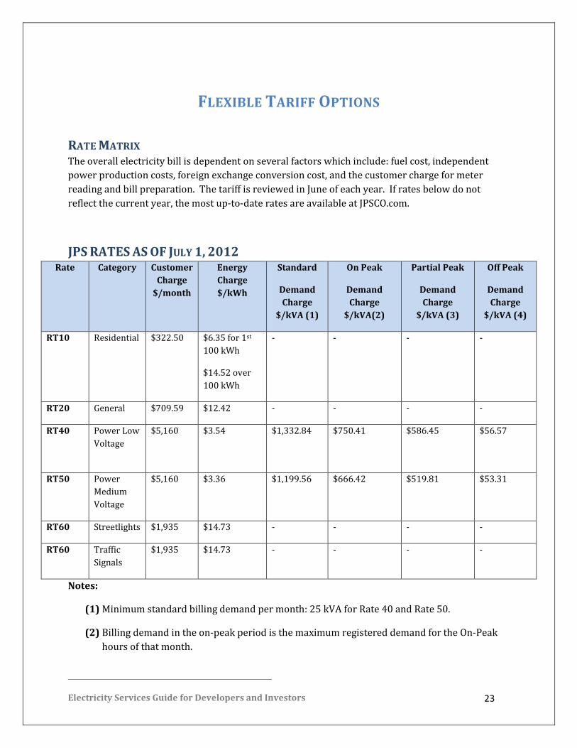
RATE MATRIX The overall electricity bill is dependent on several factors which include: fuel cost, independent
power production costs, foreign exchange conversion cost, and the customer charge for meter
reading and bill preparation. The tariff is reviewed in June of each year. If rates below do not
reflect the current year, the most up-to-date rates are available at JPSCO.com.
JPS RATES AS OF JULY 1, 2012 Rate Category Customer
Charge
$/month
Energy
Charge
$/kWh
Standard
Demand
Charge
$/kVA (1)
On Peak
Demand
Charge
$/kVA(2)
Partial Peak
Demand
Charge
$/kVA (3)
Off Peak
Demand
Charge
$/kVA (4)
RT10 Residential $322.50 $6.35 for 1st
100 kWh
$14.52 over
100 kWh
- - - -
RT20 General $709.59 $12.42 - - - -
RT40 Power Low
Voltage
$5,160
$3.54 $1,332.84 $750.41 $586.45 $56.57
RT50 Power
Medium
Voltage
$5,160 $3.36 $1,199.56 $666.42 $519.81 $53.31
RT60 Streetlights $1,935 $14.73 - - - -
RT60 Traffic
Signals
$1,935 $14.73 - - - -
Notes:
(1) Minimum standard billing demand per month: 25 kVA for Rate 40 and Rate 50.
(2) Billing demand in the on-peak period is the maximum registered demand for the On-Peak
hours of that month.
Electricity Services Guide for Developers and Investors 24
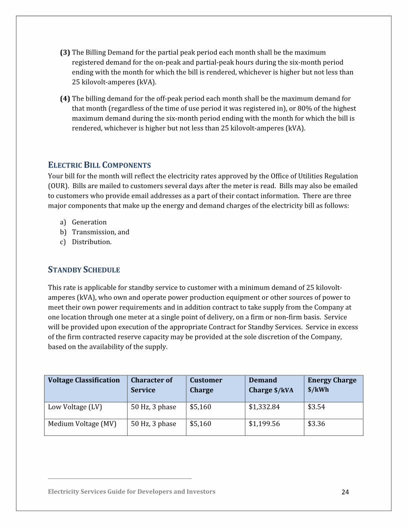
(3) The Billing Demand for the partial peak period each month shall be the maximum
registered demand for the on-peak and partial-peak hours during the six-month period
ending with the month for which the bill is rendered, whichever is higher but not less than
25 kilovolt-amperes (kVA).
(4) The billing demand for the off-peak period each month shall be the maximum demand for
that month (regardless of the time of use period it was registered in), or 80% of the highest
maximum demand during the six-month period ending with the month for which the bill is
rendered, whichever is higher but not less than 25 kilovolt-amperes (kVA).
ELECTRIC BILL COMPONENTS Your bill for the month will reflect the electricity rates approved by the Office of Utilities Regulation
(OUR). Bills are mailed to customers several days after the meter is read. Bills may also be emailed
to customers who provide email addresses as a part of their contact information. There are three
major components that make up the energy and demand charges of the electricity bill as follows:
a) Generation
b) Transmission, and
c) Distribution.
STANDBY SCHEDULE
This rate is applicable for standby service to customer with a minimum demand of 25 kilovolt-
amperes (kVA), who own and operate power production equipment or other sources of power to
meet their own power requirements and in addition contract to take supply from the Company at
one location through one meter at a single point of delivery, on a firm or non-firm basis. Service
will be provided upon execution of the appropriate Contract for Standby Services. Service in excess
of the firm contracted reserve capacity may be provided at the sole discretion of the Company,
based on the availability of the supply.
Voltage Classification Character of
Service
Customer
Charge
Demand
Charge $/kVA
Energy Charge
$/kWh
Low Voltage (LV) 50 Hz, 3 phase $5,160 $1,332.84 $3.54
Medium Voltage (MV) 50 Hz, 3 phase $5,160 $1,199.56 $3.36

Electricity Services Guide for Developers and Investors 25
TIME OF USE RATES The Time-of-Use facility was established to encourage large customers to move some of their
operations to the off-peak or partial peak period to improve their load factor and realize savings, as
well as reduce the demand for on-peak energy. Hence, rates for the off-peak and partial-peak
periods are therefore lower.
The time-of use periods are as follows:
On-Peak Monday - Friday 6:00 p.m. to 10:00 p.m.
Partial-Peak Monday-Friday 6:00 a.m. to 6:00 p.m.
And weekends and public holidays 6:00 p.m.
to 10:00 p.m.
Off-Peak Monday – Friday 10:00 p.m. to 6:00 a.m., And on weekends and
public holidays all hours except 6 p.m. to 10
p.m., which are partial-peak hours

Electricity Services Guide for Developers and Investors 26
TRANSFORMER OWNERSHIP
SINGLE PHASE TRANSFORMER PADS: The prefabricated Single Phase Transformer Pad is constructed of reinforced concrete having the
following dimensions:
Overall
Thickness - 15 cm/6 inches
Width - 127 cm/50 inches
Length - 127 cm/50 inches
Slot
Width - 58 cm/23 inches
Length - 23 cm/9 inches
The Pad has 2.5 cm (1 inch) chamfer along its top edges as well as a similar chamfer along
the bottom edges of the Slot.
TRANSFORMERS – SINGLE PHASE, PAD-MOUNTED:
a) 25 kVA (13800:120/240)
b) 37.5kVA (13800:120/240)
c) 50 kVA (13800:120/240)
d) 100 kVA (13800:120/240)
e) 167 kVA (13800:120/240)
f) 25 kVA (13800 x 6900:120/240)
g) 37.5kVA (13800x6900:120/240)

Electricity Services Guide for Developers and Investors 27
h) 50 kVA (13800 x 6900:120/240)
i) 100 kVA (13800 x 6900:120/240)
j) 150kVA (13800 x 6900:120/240)
“(a)” to “(e)” are suitable for use on 13.8/23.9kV Wye (Star) multi-grounded systems.
“(f)” to “(j)” are suitable for use on the above systems as well as 6.9/11.95kV Wye (Star)
multi-grounded systems.
All of the above transformers are of the Dead-front, Loop-feed type. They are also
specifically designed with bushings positioned for Straight-up feed using EPDM encased
separable connectors.
The transformers are fully enclosed and require no fences. Transformers may be connected
Open-Wye (Star) Open Delta for Three Phase operation.
TRANSFORMER – THREE PHASE, PAD-MOUNTED, SUBSTATION TYPE:
(a) 500 kVA (24000:120/240 x 240/415)
(b) 750kVA (2400:120/240 x 240/415)
(c) 1000 kVA (24000:120/240 x 240/415)
(d) 1500 kVA (24000:120/240 x 240/415)
(e) 2000 kVA (24000:120/240 x 240/415)
(f) 2500 kVA (24000:120/240 x 240/415)
(g) 3000 kVA (24000:120/240 x 240/415)
(h) 5000 kVA (24000:120/240 x 240/415)
(i) 500 kVA (24000 x 11950 x 13800 x 6900 : 120/240 x 240/415)
(j) 750kVA (24000 x 11950 x 13800 x 6900 : 120/240 x 240/415)

Electricity Services Guide for Developers and Investors 28
(k) 1000 kVA (24000 x 11950 x 13800 x 6900 : 120/240 x 240/415)
(l) 1500 kVA (24000 x 11950 x 13800 x 6900 : 120/240 x 240/415)
(m) 2000 kVA (24000 x 11950 x 13800 x 6900 : 120/240 x 240/415)
(n) 2500 kVA (24000 x 11950 x 13800 x 6900 : 120/240 x 240/415)
(o) 3000 kVA (24000 x 11950 x 13800 x 6900 : 120/240 x 240/415)
(p) 5000 kVA (24000 x 11950 x 13800 x 6900 : 120/240 x 240/415)
“(a)” to “(h)” are suitable for use on 13.8/23.9kV Wye (Star) multi-grounded systems.
“(i)” to “(p)” are suitable for use on the 13.8/24kV systems as well as 13.8kV Delta,
6.9/11.95kV Wye (Star) multi-grounded systems and 6.9kV Delta systems.
All of the above transformers are of the Padmounted substation type. These require
enclosure by fences (typically chain-link type). JPS will access these enclosure only, once
JPS has taken over the installation.
They are of the H.V, cable-entry type that in turn will require ducting (typically 150 mm/6-
inch PVC conduit with 3 x #1/0 AWG Aluminum XLPE Single Core cables) from the JPS
riser pole to the Primary junction box of the transformer. The ducting is also required for
the cables that will be terminated on the Secondary side of the transformer.
The customer is responsible for all civil works to include the construction of the plinth and
fenced enclosure where required. Also all secondary installations are the responsibility of
the customers.
The transformers are mounted on a reinforced concrete pad consisting of a slot with
appropriate dimensions.

Electricity Services Guide for Developers and Investors 29
SWITCHGEAR – THREE PHASE, PAD-MOUNTED, DEAD-FRONT TYPE:
(a) One input - One Output
(b) Two Inputs - One Output
(c) Two Inputs - Two Outputs
(d) One Input - Three Outputs
All of the above switchgears are of the dead-front, pad-mounted self-contained type. These
do not require additional enclosures or fences and are designed for outdoor applications.
They are designed for H.V. cable-entry from underneath which in turn requires construction
of a manhole/plinth over which the unit is to be mounted.
Each set of connectors (input or output) is housed in a separate compartment of the
switchgear. The input bushings (three for each input) are of the 25 kV, 600A type and
which typically require bushing extenders, Reducing Well plugs and load-break bushing
well inserts as accessories. Alternately, inputs may be terminated using 25kV, 600A T-body
cable terminators.
The output connections are made via load-break bushing well inserts. All outputs are fused
using power fuses.
All cables to the switchgear are terminated using 25kV 200A elbow terminators or 25kV,
600A T-body terminators.
“(a)” is used to provide switching facilities and fusing for a single transformer.
This is required on a single transformer circuit, when the transformer is customer-owned
or to supply a single transformer at the end of an underground network.

Electricity Services Guide for Developers and Investors 30
“(b)” is normally used to create a branch on an underground circuit in order to supply a
transformer (via output). “(b)” may also be used to provide a dual source to the above-
mentioned transformer (connecting each input to a separate source).
“( c) is typically used to create two (2) branches on an underground circuit in order to
supply two (2) transformers (via the outputs). “( c )” may also be used to provide a dual
source to the above-mentioned transformers (connecting each input to a separate source).
“(d)” is used to provide fusing and isolating switching facilities for three (3) transformers at
the end of an underground circuit.
SECTIONALIZING TERMINALS – PAD MOUNTED, DEAD-FRONT TYPE:
(a) Three Junction - Single Phase, 25kV
(b) Three Junction - Three Phase, 25kV
All of the above Sectionalizing Terminals are of the pad mounted self-contained type. These
do not require additional enclosures or fences and are designed for outdoor applications.
They are designed for H.V. cable-entry from underneath.
All connections are made via load-break junctions utilizing 25kV, 200A Elbow Terminators
to terminate cables.
Sectionalizing terminals may be used when underground cables must be sectionalized or
where connections must be made to an existing circuit.

Electricity Services Guide for Developers and Investors 31
UNDERGROUND H.V. CABLES
a) #1/0 AWG, Aluminium, Single Core, 25kV Class, XLP cable
b) #4/0 AWG, Aluminium, Single Core, 25kV Class, XLP cable
c) 600 kcmil Copper, Single Core, 25kV Class, XLP cable
d) 750 kcmil Copper, Single Core, 25kV Class, XLP cable
“(a)” is the size cable used for most residential developments as far as Single Phase circuits
are concerned. It is also used to supply most Three Phase requirements, i.e. Pad mounted
transformers up to 5 MVA and Three Phase underground feeders.
“(b)” is used where the Three Phase loading requirements warrant the use of a larger cable,
typically for supplying commercial and industrial developments.
“(c )” is used where a JPS Trunk Feeder passes through the development.
“(d )” is used on JPS Main Distribution Feeders.
All cables above are 25kV Class, Single Core, XLP cables, with compact round conductors
and copper concentric neutrals and a PVC jacket.
UNDERGROUND L.V. (600V CLASS) CABLE:
(a) #4 AWG Triplex
(b) #2 AWG Triplex
( c) #2/0 AWG Triplex
(d) #4/0 AWG Triplex
(e) #2/0 AWG Triplex (Doubled)
(f) #4/0 AWG Triplex (Doubled)
(g) #2/0 AWG Quadruplex
(h) #4/0 AWG Quadruplex

Electricity Services Guide for Developers and Investors 32
(i) #2/0 AWG Quadruplex (Doubled)
(j) #4/0 AWG Quadruplex (Doubled)
All cables in the Table are 1350-H19 Aluminium with XLP covering, (ASTM B-230 & B-231),
600V rating for underground Secondary use.
The cables are used for both Secondary circuits and Service connections. They are selected
according to the Loading and Voltage Drop requirements.

Electricity Services Guide for Developers and Investors 33
CONDUCTORS: All Secondary Conductors should meet the following standards:
a) 77.47 kcmil (#2 AWG ACSR Eq.) AAAC (Code Name “Ames”)
b) 155.4 kcmil (2/0 AWG ACSR Eq.) AAAC (Code Name “Anaheim”)
c) 394.5 kcmil AAAC (Code Name “Canton”).
Secondary conductors for typical development are:
“(b)” for Phase conductors and “(a)” for neutral conductors.
“(a)” is used for Primary Phase conductors and neutrals (Wye – Star – systems only) in the
typical development.
“(b)” and “(c)” are typically used for higher loads as required.
TRANSFORMERS – POLE-MOUNTED:
a) 10 kVA (13800:120/240), Single Phase
b) 15kVA (13800:120/240), Single Phase
c) 25 kVA (13800:120/240), Single Phase
d) 50 kVA (13800:120/240), Single Phase
e) 100 kVA (13800:120/240), Single Phase
f) 10 kVA (13800 x 6900:120/240), Single Phase (Dual Voltage)
g) 15kVA (13800 x 6900:120/240), Single Phase (Dual Voltage)
h) 25 kVA (13800 x 6900:120/240), Single Phase Dual Voltage)
i) 50 kVA (13800 x 6900:120/240), Single Phase Dual Voltage)
j) 100 kVA (13800 x 6900:120/240), Single Phase Dual Voltage)

Electricity Services Guide for Developers and Investors 34
“(a)” to “(e)” are suitable for use on 13.8kV Delta and 13.8/23.9kV Wye (Star) multi-grounded
systems.
“(f)” to “(j)” are suitable for use on 6.9/12kV Wye (Star) and 13.8/24 kV Systems
Transformers may be connected for Open Wye (Star) – Open Delta, Three Phase operation.

Electricity Services Guide for Developers and Investors 35
STREET LIGHTING
STREET (ROADWAY) LIGHTING
Cost of street light installation shall be borne by the Developer
For lighting systems which are planned for publicly owned roads, the Developer should be
aware that JPS will take over (own and maintain) the system only under the following
conditions:
a) The system is designed and constructed to consist of materials and to JPS’ Standard and the
quality of workmanship and grade of construction are acceptable to JPS.
b) The Ministry of Local Government has approved the street light request from relevant
Parish Council and instructs JPS accordingly.
c) The system has been approved by the Government Electrical Inspectorate.
d) Typically, developments that will contain publicly owned roads will have the lighting
provided by JPS at some date after the completion of the development. JPS will do this on
request from the Ministry of Local Government. The applicable Parish Council shall be
contacted concerning these arrangements.
e) This type of installation will be completed on existing JPS poles in the case of overhead
supplies or on new Street Lighting Standards in the case of underground supplies.

Electricity Services Guide for Developers and Investors 36
STREET LIGHTING FIXTURES
a) 100 Watt HPS (High Pressure Sodium) complete with 100W lamp and photoelectric control.
b) 150 Watt HPS (High Pressure Sodium) complete with 150W lamp and photoelectric control.
c) 250 Watt HPS (High Pressure Sodium) complete with 250W lamp and photoelectric control.
d) 400 Watt HPS (High Pressure Sodium) complete with 400W lamp and photoelectric control.
e) 0.6 m/2ft. Bracket
f) 1.2 m/4ft. Bracket
g) 1.8 m/6ft. Bracket
All luminaries are of the enclosed type with separate access to Ballast and Optical
Assemblies. Positioning of the lamp socket controls all light distribution.
All brackets are of the “upsweep” type, fabricated from 50 mm/2 inch diameter, tubular
6061-T6 Aluminum Alloy.
“(a)” is typically used with “(e)”.
“(b)” is typically used with “(e)” or “(f)”.
“( c)” and “(d)” are typically used with “(g)”.
STREET-LIGHTING STANDARDS
a) 12.5 m/41 ft. (Single Arm)
b) 12.5 m/41 ft. (Double Arm)
c) 9.5 m/31 ft. (Single Arm)
d) 9.5 m/31 ft. (Double Arm)
e) 12 m /40ft (single or double)

Electricity Services Guide for Developers and Investors 37
“(a)” to “(d)” are fabricated from 6061-T6 Tubular Aluminium Alloy and “(e)” is
constructed using concrete.
“(a)” is used to provide a mounting height of 10.7 m/35 ft.
“(b)” is used to provide a mounting height of 7.6 m/25 ft.

Electricity Services Guide for Developers and Investors 38
JOINT USE
CLEARANCES Where JPS will construct the lines for the development, the design shall incorporate adequate
clearances for joint use of pole-lines by the telephone utility, providing that there is a clear
intention by that utility to utilize the pole lines for that purpose. The design shall provide a
minimum clearance of 1.07 m/3.5 ft. between any telephone cable and the lowest energized bare
conductor (this does not include ground leads). In addition, any such design shall allow for a
minimum attachment height for the telephone cable of 5.5 m/18 ft. on any roadway in the
development.
UNDERGROUND LINES Lines that are to be placed underground, may have common trenching with other utilities,
providing that JPS’ cables are placed below those of the telephone utility, CATV (Cable TV), street
lighting, private low voltage circuits and data communication lines. Other types of circuits require
separate trenches.
a) All lines in the common trench shall be installed separately in ducts.
b) The developer shall not assume joint use of manholes, except with the expressed and
written permission of JPS.
c) The developer shall not install or permit or arrange for any other attachments (such as
CATV cable), private streetlights, potheads, meter sockets, etc.) without the expressed and
written permission to JPS. Any discussions regarding permission for attachments to JPS
structures should be had with the JPS Engineering Department or the JPS District Office.

Electricity Services Guide for Developers and Investors 39
STANDBY POWER
SAFETY SWITCH Where standby power is to be installed at various locations within the development, the developer
shall ensure that a safety switch of suitable rating is installed between the incoming JPS supply, the
standby generator bus and the future JPS customer load at each installation.
Developers should note that such facilities are generally installed to meet individual user
requirements (one generator per user) or for providing standby power to common areas in
Residential Housing Developments, Industrial and Commercial complexes.
Where developers plan to install switching facilities to permit individual users to avail themselves
of the common area standby generating service, the developer shall not install meters for the
purpose of determining electricity consumption and subsequent billing of “customers” for the
standby electricity consumption.
Electricity Services Guide for Developers and Investors 40
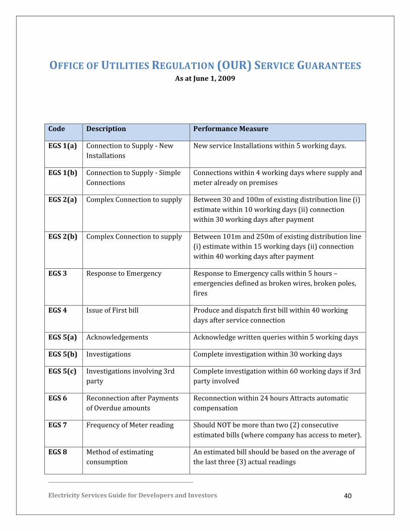
OFFICE OF UTILITIES REGULATION (OUR) SERVICE GUARANTEES As at June 1, 2009
Code Description Performance Measure
EGS 1(a) Connection to Supply - New
Installations
New service Installations within 5 working days.
EGS 1(b) Connection to Supply - Simple
Connections
Connections within 4 working days where supply and
meter already on premises
EGS 2(a) Complex Connection to supply Between 30 and 100m of existing distribution line (i)
estimate within 10 working days (ii) connection
within 30 working days after payment
EGS 2(b) Complex Connection to supply Between 101m and 250m of existing distribution line
(i) estimate within 15 working days (ii) connection
within 40 working days after payment
EGS 3 Response to Emergency Response to Emergency calls within 5 hours –
emergencies defined as broken wires, broken poles,
fires
EGS 4 Issue of First bill Produce and dispatch first bill within 40 working
days after service connection
EGS 5(a) Acknowledgements Acknowledge written queries within 5 working days
EGS 5(b) Investigations Complete investigation within 30 working days
EGS 5(c) Investigations involving 3rd
party
Complete investigation within 60 working days if 3rd
party involved
EGS 6 Reconnection after Payments
of Overdue amounts
Reconnection within 24 hours Attracts automatic
compensation
EGS 7 Frequency of Meter reading Should NOT be more than two (2) consecutive
estimated bills (where company has access to meter).
EGS 8 Method of estimating
consumption
An estimated bill should be based on the average of
the last three (3) actual readings
Electricity Services Guide for Developers and Investors 41
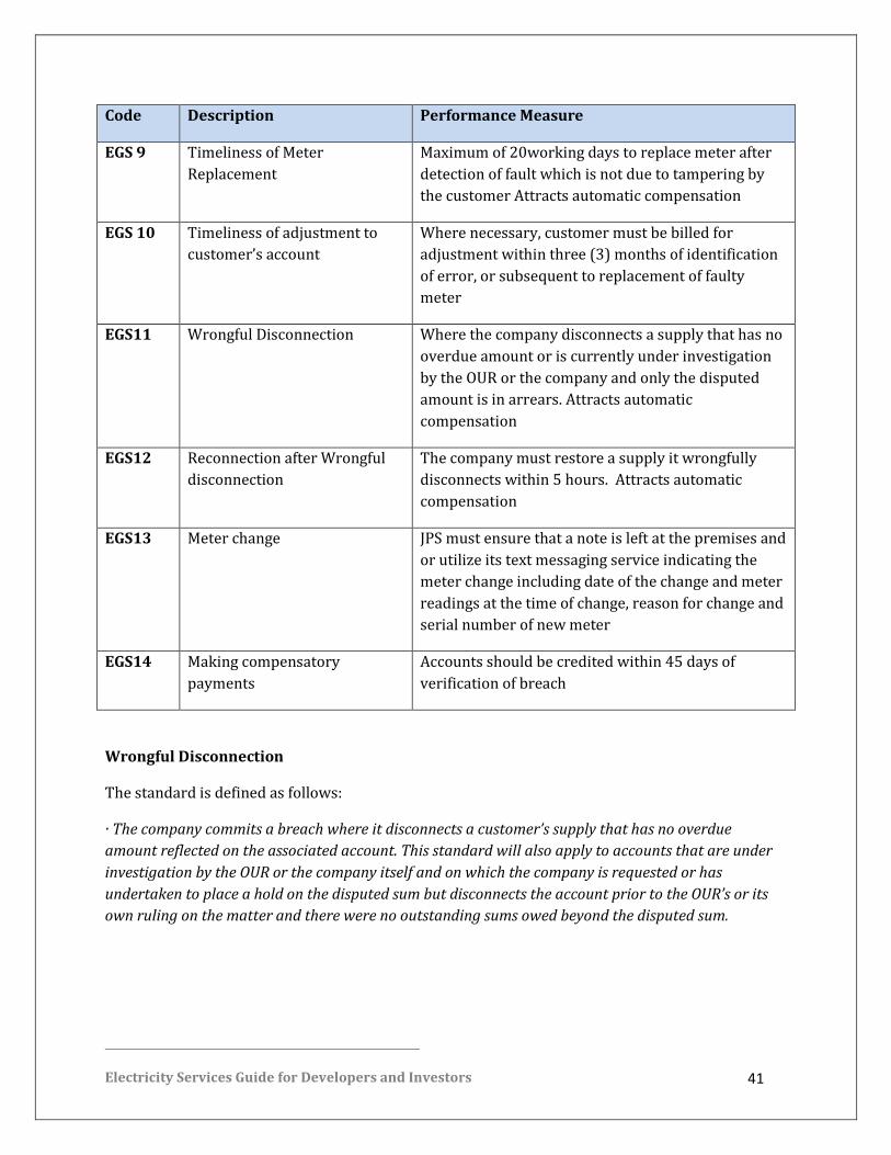
Code Description Performance Measure
EGS 9 Timeliness of Meter
Replacement
Maximum of 20working days to replace meter after
detection of fault which is not due to tampering by
the customer Attracts automatic compensation
EGS 10 Timeliness of adjustment to
customer’s account
Where necessary, customer must be billed for
adjustment within three (3) months of identification
of error, or subsequent to replacement of faulty
meter
EGS11 Wrongful Disconnection Where the company disconnects a supply that has no
overdue amount or is currently under investigation
by the OUR or the company and only the disputed
amount is in arrears. Attracts automatic
compensation
EGS12 Reconnection after Wrongful
disconnection
The company must restore a supply it wrongfully
disconnects within 5 hours. Attracts automatic
compensation
EGS13 Meter change JPS must ensure that a note is left at the premises and
or utilize its text messaging service indicating the
meter change including date of the change and meter
readings at the time of change, reason for change and
serial number of new meter
EGS14 Making compensatory
payments
Accounts should be credited within 45 days of
verification of breach
Wrongful Disconnection
The standard is defined as follows:
· The company commits a breach where it disconnects a customer’s supply that has no overdue
amount reflected on the associated account. This standard will also apply to accounts that are under
investigation by the OUR or the company itself and on which the company is requested or has
undertaken to place a hold on the disputed sum but disconnects the account prior to the OUR’s or its
own ruling on the matter and there were no outstanding sums owed beyond the disputed sum.
Electricity Services Guide for Developers and Investors 42
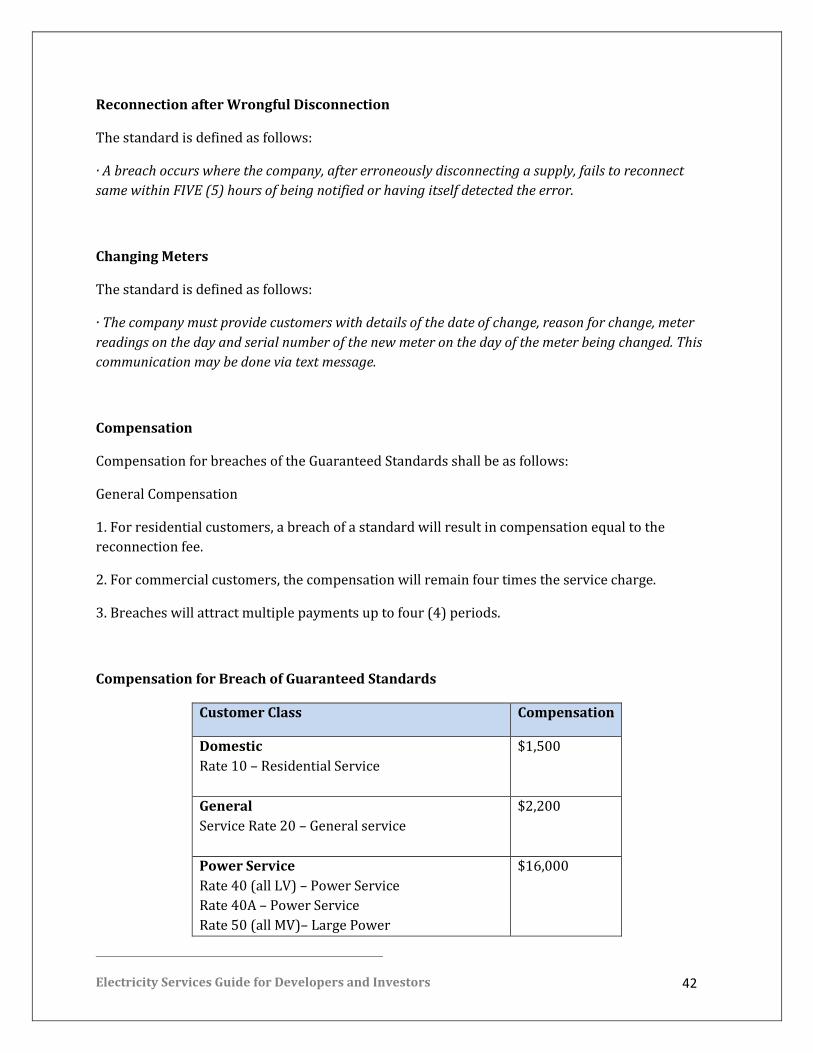
Reconnection after Wrongful Disconnection
The standard is defined as follows:
· A breach occurs where the company, after erroneously disconnecting a supply, fails to reconnect
same within FIVE (5) hours of being notified or having itself detected the error.
Changing Meters
The standard is defined as follows:
· The company must provide customers with details of the date of change, reason for change, meter
readings on the day and serial number of the new meter on the day of the meter being changed. This
communication may be done via text message.
Compensation
Compensation for breaches of the Guaranteed Standards shall be as follows:
General Compensation
1. For residential customers, a breach of a standard will result in compensation equal to the
reconnection fee.
2. For commercial customers, the compensation will remain four times the service charge.
3. Breaches will attract multiple payments up to four (4) periods.
Compensation for Breach of Guaranteed Standards
Customer Class Compensation
Domestic
Rate 10 – Residential Service
$1,500
General
Service Rate 20 – General service
$2,200
Power Service
Rate 40 (all LV) – Power Service
Rate 40A – Power Service
Rate 50 (all MV)– Large Power
$16,000

Electricity Services Guide for Developers and Investors 43
SPECIAL COMPENSATION
Wrongful Disconnection
1. Compensation for wrongful disconnection will be TWO (2) times the reconnection fee for residential
customers and FIVE (5) times the service charge for Commercial customers.
2. Reconnection after wrongful disconnection standard when breached will attract compensation of
TWO (2) times the reconnection fee for residential customers and FIVE (5) times the service charge for
commercial customers.
Automatic compensation
The company will be required to automatically apply the necessary compensation to accounts for the
following breaches:
· Wrongful Disconnection
· Reconnection after Wrongful Disconnection
· Reconnection after Payment of Overdue Amounts
· Meter Replacement
Automatic Compensation will be applicable where there is a breach which is brought to the
attention of the company, as well as those breaches, which the company itself recognizes.
Automatic compensation becomes effective January 4, 2010. Customers will be required to submit
claims prior to the effective date.

Electricity Services Guide for Developers and Investors 44
JPS reserves the right not to make a payment where it has reasonable grounds to believe that the
claim is fraudulent or did not arise from a genuine complaint or query by the customer. In such a
case, the matter shall be referred to the OUR to be determined.
The Claim Process
If you feel we have breached a standard, you may claim for compensation in writing through a letter
outlining the damages and costs. It can be delivered to your nearest JPS office or sent by post to the
Claims & Insurance Department, JPS, 6 Knutsford Boulevard, Kingston 5. You have up to 30 days
after the occurrence of the breach to submit a claim to JPS.
Electricity Services Guide for Developers and Investors 45
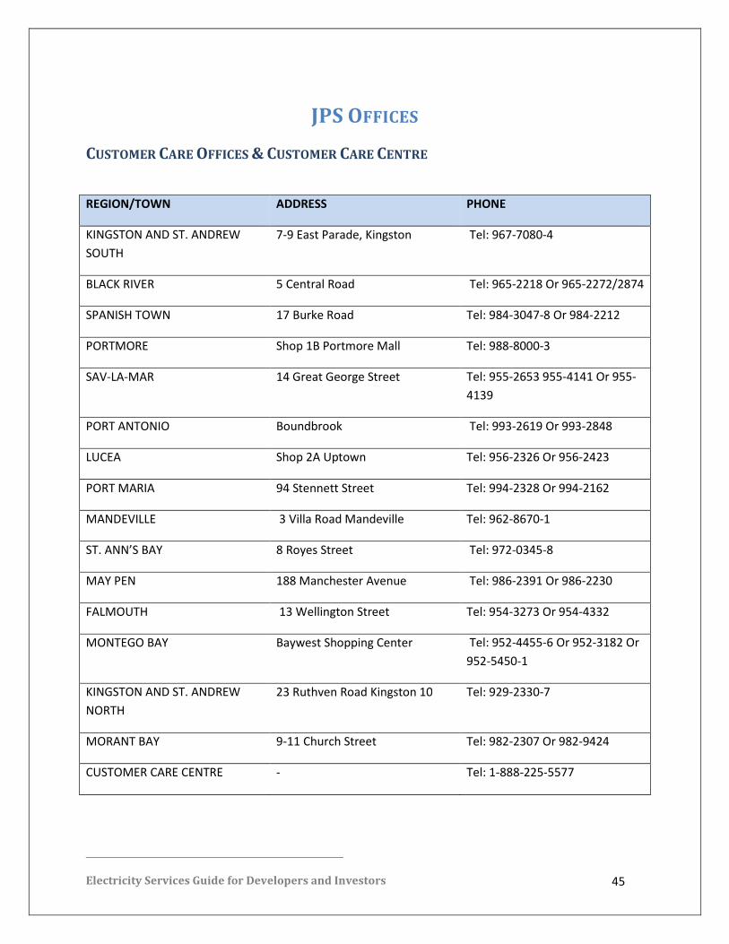
JPS OFFICES
CUSTOMER CARE OFFICES & CUSTOMER CARE CENTRE
REGION/TOWN ADDRESS PHONE
KINGSTON AND ST. ANDREW
SOUTH
7-9 East Parade, Kingston Tel: 967-7080-4
BLACK RIVER 5 Central Road Tel: 965-2218 Or 965-2272/2874
SPANISH TOWN 17 Burke Road Tel: 984-3047-8 Or 984-2212
PORTMORE Shop 1B Portmore Mall Tel: 988-8000-3
SAV-LA-MAR 14 Great George Street Tel: 955-2653 955-4141 Or 955-
4139
PORT ANTONIO Boundbrook Tel: 993-2619 Or 993-2848
LUCEA Shop 2A Uptown Tel: 956-2326 Or 956-2423
PORT MARIA 94 Stennett Street Tel: 994-2328 Or 994-2162
MANDEVILLE 3 Villa Road Mandeville Tel: 962-8670-1
ST. ANN’S BAY 8 Royes Street Tel: 972-0345-8
MAY PEN 188 Manchester Avenue Tel: 986-2391 Or 986-2230
FALMOUTH 13 Wellington Street Tel: 954-3273 Or 954-4332
MONTEGO BAY Baywest Shopping Center Tel: 952-4455-6 Or 952-3182 Or
952-5450-1
KINGSTON AND ST. ANDREW
NORTH
23 Ruthven Road Kingston 10 Tel: 929-2330-7
MORANT BAY 9-11 Church Street Tel: 982-2307 Or 982-9424
CUSTOMER CARE CENTRE - Tel: 1-888-225-5577

Electricity Services Guide for Developers and Investors 46
FOR TELEPHONE QUERIES For questions regarding new developments please call JPS’ Economic Development
Manager at 876-935-3144 between the hours of 8:00am and 5:00pm or our 24-hour
Customer Care Centre at 1-888-225-5577 (1-888-CALLJPS) or 1-888-935-5577. You may
also visit any of our Customer Care Offices nearest you.
The JPS Head Office is located at 6 Knutsford Boulevard, Kingston 5, Jamaica, West Indies.
The Marketing & Energy Services Manager is located at the Head Office, and may be
contacted directly at (876)935-3508.
You may access our website contact page at www.jpsco.com anytime or send us an email at
[email protected]. Our general office hours are 8:00am to 5:00pm Monday to
Thursday and 8:00am to 4:30pm on Fridays.