For Console Software Version 1.3.x & Up - Strand …€¦ · For Console Software Version 1.3.x &...
64
For Console Software Version 1.3.x & Up
Transcript of For Console Software Version 1.3.x & Up - Strand …€¦ · For Console Software Version 1.3.x &...

For Console Software Version 1.3.x & Up

Operation Guide 250ML Lighting Control Consoles
Philips Strand Lighting Offices
The material in this manual is for information purposes only and is subject to change without notice. Philips StrandLighting assumes no responsibility for any errors or omissions which may appear in this manual. For comments andsuggestions regarding corrections and/or updates to this manual, please contact your nearest Philips Strand Lightingoffice.
El contenido de este manual es solamente para información y está sujeto a cambios sin previo aviso. Philips StrandLighting no asume responsabilidad por errores o omisiones que puedan aparecer. Cualquier comentario, sugerenciao corrección con respecto a este manual, favor de dirijirlo a la oficina de Philips Strand Lighting más cercana.
Der Inhalt dieses Handbuches ist nur für Informationszwecke gedacht, Aenderungen sind vorbehalten. PhilipsStrand Lighting uebernimmt keine Verantwortung für Fehler oder Irrtuemer, die in diesem Handbuch auftreten. FürBemerkungen und Verbesserungsvorschlaege oder Vorschlaege in Bezug auf Korrekturen und/oderAktualisierungen in diesem Handbuch, moechten wir Sie bitten, Kontakt mit der naechsten Philips Strand Lighting-Niederlassung aufzunehmen.
Le matériel décrit dans ce manuel est pour information seulement et est sujet à changements sans préavis. Lacompagnie Philips Strand Lighting n'assume aucune responsibilité sur toute erreur ou ommission inscrite dans cemanuel. Pour tous commentaires ou suggestions concernant des corrections et/ou les mises à jour de ce manuel,veuillez s'il vous plait contacter le bureau de Philips Strand Lighting le plus proche.
Note: Information contained in this document may not be duplicated in full or in part by any person without prior written approval of Philips Strand Lighting. Its sole purpose is to provide the user with conceptual information on the equipment mentioned. The use of this document for all other purposes is specifically prohibited.
Document Number: 2-450335-010 Rev. D
Version as of: 27 February 2015
250ML Lighting Control Console Operation Guide
©2015 Philips Group. All rights reserved.
Philips Strand Lighting - Dallas10911 Petal StreetDallas, TX 75238
Tel: +1 214-647-7880Fax: +1 214-647-8030
Philips Strand Lighting - Auckland19-21 Kawana Street
Northcote, Auckland 0627New Zealand
Tel: +64 9 481 0100Fax: +64 9 481 0101
Philips Strand Lighting - AsiaUnit C, 14/F, Roxy Industrial Centre
No. 41-49 Kwai Cheong RoadKwai Chung, N.T., Hong Kong
Tel: +852 2796 9786Fax: +852 2798 6545
Philips Strand Lighting - EuropeRondweg zuid 85
Winterswijk 7102 JDThe Netherlands
Tel: +31 (0) 543-542516
Website:www.strandlighting.com
1

250ML Lighting Control Consoles Operation Guide
IMPORTANT INFORMATION
Warnings and Notices
Additional Resources for DMX512For more information on installing DMX512 control systems, the following publication is available for purchasefrom the United States Institute for Theatre Technology (USITT), "Recommended Practice for DMX512: A Guidefor Users and Installers, 2nd edition" (ISBN: 9780955703522). USITT Contact Information:
USITT315 South Crouse Avenue, Suite 200Syracuse, NY 13210-1844Phone: 1.800.938.7488 or 1.315.463.6463www.usitt.org
Philips Strand Lighting Limited Two-Year WarrantyPhilips Strand Lighting offers a two-year limited warranty of its products against defects in materials orworkmanship from the date of delivery. A copy of Philips Strand Lighting two-year limited warranty containingspecific terms and conditions can be obtained by contacting your local Philips Strand Lighting office.
When using electrical equipment, basic safety precautions should always be followed including the following:
a. READ AND FOLLOW ALL SAFETY INSTRUCTIONS.
b. Do not use outdoors.
c. Keep dry. This product is not waterproof, and may malfunction if exposed to high levels of humidity. Rusting of the internal mechanism can cause irreparable damage.
d. Do not mount near gas or electric heaters.
e. Keep away from strong magnetic fields. Do not use or place this device in vicinity of equipment that generates strong electromagnetic radiation or magnetic fields. Strong static charges or strong magnetic fields produced by equipment such as radio transmitters could interfere with the display or affect the product's internal circuitry.
f. Equipment should be mounted in locations and at heights where it will not readily be subjected to tampering by unauthorized personnel.
g. The use of accessory equipment not recommended by the manufacturer may cause an unsafe condition.
h. Do not use this equipment for other than intended use.
i. Refer service to qualified personnel.
SAVE THESE INSTRUCTIONS.
WARNING: You must have access to a main circuit breaker or other power disconnect device before installing any wiring. Be sure that power is disconnected by removing fuses or turning the main circuit breaker off before installation. Installing the device with power on may expose you to dangerous voltages and damage the device. A qualified electrician must perform this installation.
WARNING: Refer to National Electrical Code® and local codes for cable specifications. Failure to use proper cable can result in damage to equipment or danger to personnel.
WARNING: This equipment is intended for installation in accordance with the National Electric Code® and local regulations. It is also intended for installation in indoor applications only. Before any electrical work is performed, disconnect power at the circuit breaker or remove the fuse to avoid shock or damage to the control. It is recommended that a qualified electrician perform this installation.
2

Operation Guide 250ML Lighting Control Consoles
TABLE OF CONTENTS
Philips Strand Lighting Offices .......................................................................................................................................... 1IMPORTANT INFORMATION
Warnings and Notices......................................................................................................................................................... 2Additional Resources for DMX512.................................................................................................................................... 2Philips Strand Lighting Limited Two-Year Warranty........................................................................................................ 2
TABLE OF CONTENTSPREFACE
About this Guide......................................................................................................................................................................... 5Included Items............................................................................................................................................................................. 5
OVERVIEWBasic Console Layout ................................................................................................................................................................. 6Console Features and Connections ............................................................................................................................................. 7
Power Switch ...................................................................................................................................................................... 7Power Input......................................................................................................................................................................... 7Ethernet Port (RJ45) ........................................................................................................................................................... 7Faceplate USB Port (Library Storage)................................................................................................................................ 7Rear USB Port .................................................................................................................................................................... 7VGA Out (Monitor) ............................................................................................................................................................ 7MIDI In/Thru ...................................................................................................................................................................... 7DMX512 In (1 Connection)................................................................................................................................................ 7DMX512 Out (2 Connections) ........................................................................................................................................... 7
Connecting Power....................................................................................................................................................................... 7Glossary of Terms ....................................................................................................................................................................... 7Text Conventions ........................................................................................................................................................................ 9
CONSOLE SETUPMain Menu................................................................................................................................................................................ 10
Setup ................................................................................................................................................................................. 10Record Options ................................................................................................................................................................. 10Cue Default Options ......................................................................................................................................................... 11Lock/Unlock ..................................................................................................................................................................... 11MIDI Setup ....................................................................................................................................................................... 11Playback Setup.................................................................................................................................................................. 13DMX In Setup................................................................................................................................................................... 13Display Setup.................................................................................................................................................................... 14
Patch.......................................................................................................................................................................................... 14Patching Conventions ....................................................................................................................................................... 14Patch Screen...................................................................................................................................................................... 16Viewing Patch................................................................................................................................................................... 16Range Patching ................................................................................................................................................................. 17Removing Patching Assignment....................................................................................................................................... 17Patching Intelligent Fixtures............................................................................................................................................. 17Patch/Unpatch Fixture to DMX Address.......................................................................................................................... 18Fixture Pages..................................................................................................................................................................... 20Pan/Tilt Options................................................................................................................................................................ 20
OPERATIONConsole VGA Monitor Display Attributes ............................................................................................................................... 22Console 7-Inch Display Attributes ........................................................................................................................................... 23Channels and Channel Levels................................................................................................................................................... 23
Assigning Channel Levels ................................................................................................................................................ 23Intensity on Encoder ......................................................................................................................................................... 24Releasing Channels........................................................................................................................................................... 24
Recording A Cue ...................................................................................................................................................................... 24Cue Options ...................................................................................................................................................................... 25Record (Minus Subs) Cue................................................................................................................................................. 27
Running a Cue .......................................................................................................................................................................... 27Pausing A Cue .......................................................................................................................................................................... 27Playback Operation................................................................................................................................................................... 28Cue List..................................................................................................................................................................................... 28
3 TABLE OF CONTENTS

250ML Lighting Control Consoles Operation Guide
Cue List Options ............................................................................................................................................................... 29Recording a Submaster ............................................................................................................................................................. 30
Playback Master................................................................................................................................................................ 31Submaster Pages ............................................................................................................................................................... 31Submaster Options............................................................................................................................................................ 31
Record (Minus Subs) Submaster .............................................................................................................................................. 35Recording a Playback ............................................................................................................................................................... 36
Record Playback Options.................................................................................................................................................. 37Recording an Effect .................................................................................................................................................................. 37
Record Effect Options ...................................................................................................................................................... 39Cue/Submaster Preview............................................................................................................................................................ 40Submaster List .......................................................................................................................................................................... 40
Editing a Submaster .......................................................................................................................................................... 41Editing a Submaster Effect ............................................................................................................................................... 42Edit a Submaster Playback ............................................................................................................................................... 43Submaster Pages and Paging ............................................................................................................................................ 43
FX List ...................................................................................................................................................................................... 44Recording a Group.................................................................................................................................................................... 44Applying Groups....................................................................................................................................................................... 44Basic Automated Luminaire Control ........................................................................................................................................ 45
Home................................................................................................................................................................................. 45Fixture Intensity Control................................................................................................................................................... 45Paging the Fixture Display ............................................................................................................................................... 46Tagging and Untagging .................................................................................................................................................... 46
Advanced Automated Luminaire Control................................................................................................................................. 47S6-Fan First....................................................................................................................................................................... 47S7-Fan Middle .................................................................................................................................................................. 47S8-Fan Last ....................................................................................................................................................................... 47S9-Fan V........................................................................................................................................................................... 47Shift + (Attribute Family) ................................................................................................................................................. 47
Palettes ...................................................................................................................................................................................... 47Recording a Palette ........................................................................................................................................................... 48Applying A Palette............................................................................................................................................................ 48Accessing Fixtures using Channel Numbers .................................................................................................................... 49
Focus......................................................................................................................................................................................... 49S9-Show List..................................................................................................................................................................... 50
Automated Luminaire Effects................................................................................................................................................... 50Archive...................................................................................................................................................................................... 51
Save Show......................................................................................................................................................................... 51Clear Memory / Subs ........................................................................................................................................................ 52Clear Palettes .................................................................................................................................................................... 52Default Setup .................................................................................................................................................................... 53Load Show ........................................................................................................................................................................ 53
Storing Color Mixing Fixtures on Submasters Tutorial............................................................................................................ 54For Storing All LED Parameters on a Submaster............................................................................................................. 54For Storing Changed LED Parameters on a Submaster.................................................................................................... 54
Effects Tutorial ......................................................................................................................................................................... 54Creating an Intensity Effect .............................................................................................................................................. 54
MAINTENANCEReset Desk ................................................................................................................................................................................ 57Update Software ....................................................................................................................................................................... 57Update VGA Screen ................................................................................................................................................................. 58Test Mode ................................................................................................................................................................................. 59
PRODUCT INFORMATIONSpecification ............................................................................................................................................................................. 60Console Capacities.................................................................................................................................................................... 61Principle Features ..................................................................................................................................................................... 61
4

Operation Guide 250ML Lighting Control Consoles
PREFACE
1. About this GuideCongratulations on your purchase of your Philips Strand Lighting 250ML Control Console. It is a compact lightingcontrol console, versatile, powerful, and the perfect desk to introduce you to the world of intelligent fixture control.
Every unit has been thoroughly tested and carefully packed before shipment.
Unpack the shipping carton carefully, saving the carton and all packing materials forpossible later use. Refer to"Included Items" for a complete list of items and accessoriesthat are provided as part of your console.
Note: Check carefully that your product has not been damaged and that there are no accessories missing. If your product appears to be damaged or missing any accessories, please do not use the console and contact your Authorized Philips Strand Lighting Dealer immediately.
Please read this manual carefully and thoroughly, as it gives important informationregarding safety, use and maintenance. Keep this manual with the console for possiblefuture reference.
You can use the QR code (to the right) on any QR code enabled smartphone to connect directly to the 250ML ControlConsole product page and download the product manual or other product data.
Note: This version of the Operation Guide covers software version 1.2.x. Should your 250ML Control Console need to be upgraded, go to www.strandlighting.com and click on the product downloads area in the Support section for the latest software available.
2. Included ItemsEach 250ML Lighting Control Console includes the following items:
• Lighting control console (with integrated video [VGA] card)
• Console dust cover
• Universal voltage power supply
• USB key drive
• LED desk lamp
• 250ML Console QuickStart Guide (not this document)
Note: Monitors, cables and other accessories are not included and are sold separately. For available accessories, please contact you local Authorized Strand Lighting Dealer. A list of Authorized Dealers is located on the Strand Lighting web site at www.strandlighting.com.
250ML Control ConsoleProduct Page
5 PREFACE

250ML Lighting Control Consoles Operation Guide
OVERVIEW
1. Basic Console Layout
Power Switch
DMX512A Out(2 each)
DMX512A InVGA Out(Monitor)
Power Input
Ethernet Port (RJ45)
USB Port *
MIDI In/Out
250ML Console - Rear Panel Connections
A B C D F
G
H
I
E
JL K
A. 24 Faders / SubmastersB. Playback MasterC. Programming LCD DisplayD. USB Port (showfile storage, USB key sold separately)E. Main Console LCD Color DisplayF. Grand Master
G. Black Out ButtonH. Softkeys (10 each)I. Encoders (4 each)J. Programming ButtonsK. A / B Playback Controls (with Go and Load buttons)L. 24 Bump Buttons
Legend
(*For USB LED desk lamp. Not for showfile storage.)
Basic Console Layout 6

Operation Guide 250ML Lighting Control Consoles
2. Console Features and Connections
Power SwitchTurns console On or Off. Note, turning off this switch does not disconnect power from console.
Power InputPower into console from universal (AC to DC) power supply. Refer to the QuickStart guide supplied with console onhow to connect power using provided power supply. The power supply shipped with your 250ML Control Console isan auto-ranging, universal voltage supply. It operates between 90 to 240 VAC.
Ethernet Port (RJ45)For future expansion of Ethernet protocols.
Faceplate USB Port (Library Storage)USB connection for connection of a USB drive to load libraries, save shows, or update console software.
Rear USB PortUSB port for connection of USB LED desk lamp connection. Not for showfile storage.
VGA Out (Monitor)VGA connection for driving a VGA video monitor. Refer to the QuickStart guide supplied with console for VGAconnections. Note, video monitor sold separately.
MIDI In/ThruThe console provides two standard 6-pin MIDI connectors. The MIDI In can connect to a MIDI generator and theMIDI Thru can connect to another MIDI device.
DMX512 In (1 Connection)DMX512 input connection for DMX512 signals from another console or device.
DMX512 Out (2 Connections)The console provides two standard, female XLR 5-pin connector for connecting to, and controlling, DMX512devices. DMX512 is for outputting to a universe of DMX devices for your primary output. This can include dimmers,LED fixtures, and moving lights.
Note: For more information on DMX512, refer to "Additional Resources for DMX512" on page 2.
3. Connecting Power
To connect the power supply:
Step 1. Make sure unit's power switch is set to "Off"
Step 2. Connect DC connector from power supply to DC IN on console.
Step 3. Connect power supply to AC supply source.
Step 4. Turn on console at Console On / Off Switch.
Note: You must connect the console to the lighting system via DMX512 before it is capable of providing control. Refer to the QuickStart Guide provided with the console for DMX512 connection information.
4. Glossary of TermsThis section covers some of the common terms used throughout this manual.
• Fader / Submaster / Playback - Slider hardware to control the level of stored information.
• Fader / Submaster / Playback Bump Button - button hardware that activates the stored information on the submaster or playback.
• Playback Master - a master inhibitive slider for all playback data.
7 OVERVIEW

250ML Lighting Control Consoles Operation Guide
• A and B Master - master inhibitive sliders for A and B playbacks. A is at 100% at the top end of its travel while the B is at 100% at the bottom end of its travel. This allows the execution of dipless crossfades by moving both sliders in the same direction.
• GO - advances the next available cue.
• LOAD - allows the preparation for the next cue advanced by the [GO] button.
• Programming LCD Display - this small LCD display will display pertinent information based on the active item being programmed or played back. This screen also shows the function of the four softkeys labeled (F1) - (F4).
• Programming Buttons - these allow for traditional Command Line operation for setting levels and storing items like Cues and Subs.
• Record - command used to store information.
• Cue - cues are items to be played back in time and in sequential order.
• ON - level of 100%. Example: [1] [ON]
• Thru - allows a collection of a range of channels. Example: [1] [THRU] [5] [ON].
• 0 thru 9 - numerical entry key for Command Line operation.
• Plus "+" - allows the addition of channels to a Command Line string. Example: [1] [+] [2] [ON]. Also if pressed without a pre-existing channel list, it will Page Up the channel display. If the Fixture button is selected, it will Page Up the Fixture display.
• Minus "-" - allows the subtraction of channels to a Command Line string. Example: [1] [THRU] [5] [-] [3] [ON]. This will place 1, 2, 4, and 5 at Full. Also if pressed without a pre-existing channel list, it will Page Down the chan-nel display. If the Fixture button is selected, it will Page Down the Fixture display.
• AT "@" - command that tells the desk that the next numerical entry is a level of brightness. Example: [1] [@] [5] [0] [ENTER].
• CLR - clears the Command Line plus releases channels. CLR will remove the last command entered into the Command Line. In the event that there is nothing entered into the Command Line, [CLR] [CLR] will release all Selected Channels (in the Red Box) a third [CLR] shall release all Adjusted Channels (Red Text).
• Decimal "." - allows the entry of DMX values rather than percentage values. Example: [1] [@] [.] [2] [5] [5] [ENTER].
• ENTER - allows the completion of any command entered into the Command Line. Example: [1] [@] [5] [0] [ENTER], [RECORD] [CUE] [1] [ENTER].
• Arrow Up and Arrow Down (adjacent to the small LCD screen) - Allows the ability to change pages.
• Untag - This button has multiple functions. It can untag (deselect) fixtures, attribute families or individual attri-butes. See Tagging and Untagging for details. Selecting SHIFT + UNTAG allows the user entry in the Setup pages for system configuration settings.
• Home - sets the channel or fixture back to its default position.
• Fixture - fixture is the term for attributed luminaires (LEDs and Moving Lights). This button allows access to the patched attributed luminaires.
• Position - allows access to programming for position attributes on an attributed luminaire.
• Color - allows access to programming for color attributes on an attributed luminaire.
• Beam - allows access to programming for beam parameters on an attributed luminaire.
• Effect - allows access to programming for effect parameters on an attributed luminaire.
• Group - Allows access to programming a collection of channels or fixtures.
• Grand Master - an inhibitive master for all outputting intensity levels.
• Blackout Button - single button access that will set all outputting intensity levels to zero.
Glossary of Terms 8

Operation Guide 250ML Lighting Control Consoles
• Main Console LCD Display - primary programming display. This 7-inch color display will display the Command Line, recording commands, all configuration information, 10 softkey labels and 4 encoder's informa-tion.
• Shift - used to gain access to the Setup environment as well as access to additional advanced commands.
• Shift + UNTAG = Setup
• Shift + ENTER = Encoder Intensity control on selected channels.
• Shift + Encoders = can gain access to advanced features on some items. For example, on Fade Up / Fade Down this will allow for time adjustment in 1/10th second.
5. Text ConventionsWhen a key is referred to in the manual it will be in hard brackets. For instance [RECORD] would refer to the recordbutton. A softkey command on the LCD screen will be written inside ( ). So for instance the (S9-Enter) would refer toa softkey option available on the LCD screen. For operational information, refer to "OPERATION" on page 22.
The example in Figure 1 represents any command button like Record used in teaching examples.
Figure 1: Command Button Example
The example in Figure 2 represents any bump button or softkey used in teaching examples.
Figure 2: Bump Button Example
9 OVERVIEW

250ML Lighting Control Consoles Operation Guide
CONSOLE SETUP
1. Main MenuHolding down the [SHIFT] + [UNTAG] for 3 seconds will launch into the Setup portion of the 250ML Console.
Figure 3: Main Menu
The following options are available for the 250ML Control Console:
Setup(S1 - Setup): Setup allows the user to adjust the console to work the way that's most comfortable for the user. Anyoptions within the main screen on the Setup Menu can be navigated to using Encoder D to scroll Up/Down the list ofsetup options.
Figure 4: Setup Menu
Within Setup, there are options that determine how the console functions. The setup options are…
Record OptionsRecord Options determine how the record action works. By default the Mode (which refers to the Record Mode is setto Full. That means that everything that is being outputted from the console will be stored. By pressing S1 the Modecan be changed. If the Mode is set to Partial, then the other softkeys shall control how Brightness (Intensity), Color,Beamshape and Position parameters shall be stored.
Figure 5: Record Options
SETUP
PATCH
ARCHIVE
MAINTENANCE
EXIT
S5
S1 S6
S2 S7
S10Relative
<DEFAULT OPTIONS><LOCK/ UNLOCK>
<MIDI SETUP><PLAYBACK SETUP><DMX INPUT SETUP>
Cmd: ?
SETUP MENU
S3 S8
S4 S9
<RECORD OPTIONS >
FIXTURE POSITION COLOR BEAM EFFECT
<DISPLAY SETUP>
GROUP
Main Menu 10

Operation Guide 250ML Lighting Control Consoles
When the attribute family (Position, Color or Beam) option is set to ALL, then when one parameter is adjusted, allparameters for that family will be highlighted to be stored. For example, if programming color on a 3 color LED andthe Red is adjusted, the Green and Blue will be highlighted as well.
When the attribute family option is set to CHANNEL, then when one parameter is adjusted, only that parameter willbe highlighted to be stored. For example, if programming color on a 3 color LED and the Red is adjusted, the Greenand Blue will not be highlighted.
Cue Default OptionsThe Cue Defaults determines what fade parameter you want set Colour, Beamshape and Position attributes whenrecording a cue.
The Options are:
• Snap - color, beam and position values shall output to their stored values in a zero time when the cue is activated.
• Fade - color, beam and position values shall fade with the transition of the cue using the time of the cue.
• Snap@100% - color, beam and position values shall output to the stored values in a zero time when the cue is com-pleted
Figure 6: Cue Default Options
Lock/UnlockThis features allows the locking and unlocking of the console from any accidental use.
Use Encoder D to scroll down to <Lock/Unlock>, press down on Encoder D and the Lock/Unlock option will appear.This is password protected and the password must be entered to engage/disengage this feature.
Note: The password is 168168.
Figure 7: Lock Console Screen
MIDI SetupThis feature allows the console to communicate with other consoles using the MIDI interface. MIDI In and Thru areavailable. Just connect a standard MIDI cable from a third party console to the 250ML console's MIDI In port. If you
ColourSnap
BeamshapeSnap
PositionSnap
Enter
S1 S6
FIXTURE POSITION COLOR BEAM EFFECT GROUP
**OPTIONS**
SETUP MENU
** CUE DEFAULT**
S7
S8Cmd: ?
S4 S9
S5 S10Relative
S2
S3
11 CONSOLE SETUP

250ML Lighting Control Consoles Operation Guide
need to communicate to a third console, a MIDI cable can be connected from the 250ML console's MIDI Thru port toanother third party console.
Figure 8: MIDI Setup Screen
• From the MIDI Setup screen, S1 will Enable MIDI while S2 will disable MIDI.
• Encoder A will configure the Channel (0 - 15) and Encoder D will configure the Note (0 - 127).
Note: There are different types of MIDI messages. The only one that the 250ML supports is Channel Voice. The Channel setting allows the console to listen to any channel from 0 to 15. The Note variable allows the console to listen to individual Voice Channels 0 to 127. This will control channels but not cues or submasters.
As shown in Table 1, “MIDI Messages - Available Notes,” on page 12, there are a variety of notes available.
Table 1: MIDI Messages - Available Notes
Notes DMX Channel Notes DMX Channel Notes DMX Channel Notes DMX Channel
Note 0 C-2 Channel 1 Note 32 G#0 Channel 33 Note 64 E3 Channel 65 Note 96 C6 Channel 97
Note 1 C#-2 Channel 2 Note 33 A 0 Channel 34 Note 65 F3 Channel 66 Note 97 C#6 Channel 98
Note 2 D-2 Channel 3 Note 34 A#0 Channel 35 Note 66 F#3 Channel 67 Note 98 D6 Channel 99
Note 3 D#-2 Channel 4 Note 35 B0 Channel 36 Note 67 G3 Channel 68 Note 99 D#6 Channel 100
Note 4 E-2 Channel 5 Note 36 C1 Channel 37 Note 68 G#3 Channel 69 Note 100 E6 Channel 101
Note 5 F-2 Channel 6 Note 37 C#1 Channel 38 Note 69 A3 Channel 70 Note 101 F6 Channel 102
Note 6 F#-2 Channel 7 Note 38 D1 Channel 39 Note 70 A#3 Channel 71 Note 102 F#6 Channel 103
Note 7 G-2 Channel 8 Note 39 D#1 Channel 40 Note 71 B3 Channel 72 Note 103 G6 Channel 104
Note 8 G#-2 Channel 9 Note 40 E1 Channel 41 Note 72 C4 Channel 73 Note 104 G#6 Channel 105
Note 9 A-2 Channel 10 Note 41 F1 Channel 42 Note 73 C#4 Channel 74 Note 105 A6 Channel 106
Note 10 A#-2 Channel 11 Note 42 F# 1 Channel 43 Note 74 D4 Channel 75 Note 106 A#6 Channel 107
Note 11 B-2 Channel 12 Note 43 G1 Channel 44 Note 75 D#4 Channel 76 Note 107 B6 Channel 108
Note 12 C-1 Channel 13 Note 44 G#1 Channel 45 Note 76 E4 Channel 77 Note 108 C7 Channel 109
Note 13 C#-1 Channel 14 Note 45 A1 Channel 46 Note 77 F4 Channel 78 Note 109 C#7 Channel 110
Note 14 D-1 Channel 15 Note 46 A#1 Channel 47 Note 78 F#4 Channel 79 Note 110 D7 Channel 111
Note 15 D#-1 Channel 16 Note 47 B1 Channel 48 Note 79 G4 Channel 80 Note 111 D#7 Channel 112
Note 16 E-1 Channel 17 Note 48 C2 Channel 49 Note 80 G#4 Channel 81 Note 112 E7 Channel 113
Note 17 F-1 Channel 18 Note 49 C#2 Channel 50 Note 81 A4 Channel 82 Note 113 F7 Channel 114
Note 18 F#-1 Channel 19 Note 50 D2 Channel 51 Note 82 A#4 Channel 83 Note 114 F#7 Channel 115
Note 19 G-1 Channel 20 Note 51 D#2 Channel 52 Note 83 B4 Channel 84 Note 115 G7 Channel 116
Note 20 G#-1 Channel 21 Note 52 E2 Channel 53 Note 84 C5 Channel 85 Note 116 G#7 Channel 117
Note 21 A-1 Channel 22 Note 53 F2 Channel 54 Note 85 C#5 Channel 86 Note 117 A7 Channel 118
Note 22 A#-1 Channel 23 Note 54 F#2 Channel 55 Note 86 D5 Channel 87 Note 118 A#7 Channel 119
Note 23 B-1 Channel 24 Note 55 G2 Channel 56 Note 87 D#5 Channel 88 Note 119 B7 Channel 120
Note 24 C 0 Channel 25 Note 56 G#2 Channel 57 Note 88 E5 Channel 89 Note 120 C8 Channel 121
Note 25 C# 0 Channel 26 Note 57 A2 Channel 58 Note 89 F5 Channel 90 Note 121C#8 Channel 122
Note 26 D0 Channel 27 Note 58 A#2 Channel 59 Note 90 F#5 Channel 91 Note 122 D8 Channel 123
Note 27 D#0 Channel 28 Note 59 B2 Channel 60 Note 91 G5 Channel 92 Note 123 D#8 Channel 124
Note 28 E0 Channel 29 Note 60 C3 Channel 61 Note 92 G#5 Channel 93 Note 124 E8 Channel 125
Note 29 F0 Channel 30 Note 61 C#3 Channel 62 Note 93 A5 Channel 94 Note 125 F8 Channel 126
Note 30 F# 0 Channel 31 Note 62 D3 Channel 63 Note 94 A#5 Channel 95 Note 126 F#8 Channel 127
Main Menu 12

Operation Guide 250ML Lighting Control Consoles
Playback SetupThis setting determines how the last cue in the playback responds when run sequentially.
Figure 9: Playback Setup Screen
The options are:
• (S1-PB Cue Release) whereby the last cue will be released from the playback.
• (S2-PB Cue Last Hold) whereby the playback will hold the last outputted value.
DMX In SetupThis option turns on the DMX In port on the back of the console to allow another DMX control device (like aconsole) to affect changes on the 250ML Control Console.
Figure 10: DMX In Setup Screen
The options are:
• (S1-DMX In Enable) - enable DMX input signals from another DMX control source.
• (S2-DMX In Disable) - disables DMX input signals from another DMX control source.
Once DMX In is enabled and a DMX512 cable has been connected from the DMX512 Out port on the externalconsole to the DMX In port of the 250ML console, the external console will control the first 96 channels in a 1 to 1fashion. For example, Channel 1 on the external console will control Channel 1 on the 250ML console and continuein numerical sequence up to a capacity of 96 channels.
Note 31 G0 Channel 32 Note 63 D#3 Channel 64 Note 95 B5 Channel 96 Note 127 G8 Channel 128
Notes DMX Channel Notes DMX Channel Notes DMX Channel Notes DMX Channel
13 CONSOLE SETUP

250ML Lighting Control Consoles Operation Guide
Display SetupAllows the adjustment of the backlight level settings for the color display screen on the console.
Figure 11: Display Setup Screen
The options are:
• (S1-Backlight High) - sets console display to highest brightness level.
• (S2-Backlight Medium) - sets console display to the medium brightness level.
• (S3-Backlight Low) - sets console display to lowest brightness level.
2. PatchPatch allows the operator to determine the channel and fixture numbers that control each DMX channel whether theyare a dimmer or an automated luminaire such as an LED or moving light.
The 250ML Control Console starts out with a one-to-one default patch for the capacity of the console and noautomated luminaires patched. That's 250 channels. A one-to-one patch means that each dimmer will be patched andcontrolled by a channel that is the same number. Example: Dimmer 1 is controlled by Channel 1, Dimmer 2 byChannel 2 and so on up to Dimmer 250 being controlled by Channel 250.
Patching conventional channels on the 250ML Control Console is accomplished with Setup. Press [SHIFT] +[UNTAG] to go into the Setup menu.
Press S2- Patch to go into the Patch menu.
Figure 12: Patch Menu
Patching ConventionsUse Encoder D to roll the selector up/down to DMX Patch (the active option will be in a white background) and clickon Encoder D to select DMX Patch. The monitor will now display the patch screen to show what the current channel
Patch 14

Operation Guide 250ML Lighting Control Consoles
assignments are. As shown in Figure 13, the DMX output number is the top line in white and the second line is thecontrol channel in yellow.
Figure 13: VGA Patch Screen
Note: After 250 you only see the DMX output numbers displayed. Remember that the console has a limit of 250 control channels.
15 CONSOLE SETUP

250ML Lighting Control Consoles Operation Guide
Patch ScreenThe Patch screen is the point of information for all DMX output assignments. Pressing [F3 – Patch] will open thepatch screen on the VGA monitor. From the Patch Screen, [+] and [–] will page the patch screen to view all DMXoutputs from 1 to 1024 and their patch assignment. DMX512 Port A will output 1 thru 512. The first universe ofDMX. DMX512 Port B will output 513 to 1024. The second universe of DMX.
Figure 14: Patch Screen
This is for display only. Any patch adjustment shall be done thru Setup and instructions can be found in "Setup" onpage 10.
Viewing PatchPatch can be viewed at anytime, whether in the Setup screen for patching activities or not. In many screens, the Fkeys will give you a Patch option. When the F key for Patch is pressed, the patch screen above will be displayed. The[+] and [-] keys will advance the patch screens to show you all 1024 patch outputs. Pressing the F key for Patch willreturn the console to the previous screen.
While in the Patch Menu, the F keys will access paging the patch screen with [PATCH +] and [PATCH -].
In order to change the default patch, direct your attention to the color screen on the console as illustrated in Figure15.
Figure 15: Console LCD Patch Menu
The second option (and the examples) focus on using Command Line to patch. The syntax will be [DIMMER] [@][CHANNEL] so if you need dimmer 2 to be controlled by channel 1, type [2] [@] [1] [ENTER]. Once that is done,the channel number (yellow) will have changed under dimmer 2 to reflect its assignment to channel 1. Any patchingdone will appear in the Command Line section of the color screen. Just repeat this process for any non-defaultpatching that is required. Notice that you can use THRU, + and - to speed up the patching process.
Patch 16

Operation Guide 250ML Lighting Control Consoles
Range PatchingRange patching allows the patching of multiple dimmers and multiple channels using a single command. Below aresome examples of range patching.
Should you need multiple dimmers controlled by the same channel, [DIMMER] [THRU] [DIMMER] [@][CHANNEL] [ENTER]. Example: [1] [THRU] [5] [@] [1] [ENTER] will patch dimmers 1 thru 5 to channel 1.
Should you need a consecutive dimmer range to be patched to a consecutive channel range, [DIMMER] [THRU][DIMMER] [@] [CHANNEL] [THRU] [CHANNEL] [ENTER]. Example: [1] [THRU] [5] [@] [11] [THRU] [15][ENTER] will patch dimmer 1 to channel 11, dimmer 2 to channel 12 and so on for the range limit that was entered.
Removing Patching AssignmentTo remove any patch assignment to any dimmer, just type [DIMMER] [@] [ENTER]. This will remove any channelassignment to the selected dimmer and any previous channel number (yellow) will be removed. Notice that [THRU],[+] and [-] will help you speed up the patching process.
Note: Refer to "Range Patching" (above) on how to use [THRU], [+] and [-].
Patching Intelligent FixturesIntelligent fixtures such as LEDs and Moving Lights require a more sophisticated control system and the 250MLControl Console has everything you need to get started with intelligent fixture control.
Note: There is a limit of 30 intelligent fixtures and 40 parameter capacity on the 250ML Control Console.
From the Setup menu (hold [SHIFT] + [UNTAG] for 3 seconds), press (S2 - Patch) and roll Encoder D clockwise tomove the cursor (white background) down to "Assign Fixture" and press the Encoder D to select.
Figure 16: Patching Intelligent Fixtures - Fixture Screen
From the fixture screen, select Encode D to Add a fixture.
Figure 17: Patching Intelligent Fixtures - Fixture Screen (Adding a Fixture)
17 CONSOLE SETUP

250ML Lighting Control Consoles Operation Guide
Fixtures are added from the 250ML Fixture Library via a USB key. The fixture library can be downloaded fromwww.strandlighting.com in the Support section. Select (S8 - Open) USB Library.
Figure 18: Patching Intelligent Fixtures - Fixture Library
The manufacturers shall appear on the S keys. Philips companies are on the left and other manufacturers are on theright. If you don't see the manufacturer on the existing softkeys, just roll Encoder D to advance the non-Philipsmanufacturer on the right and press the appropriate softkey. Once a manufacturer is selected, the manufacturer'smodels will appear in the center of the color screen. Rolling Encoder D up / down shall highlight each fixture type.Press Encoder D to select the appropriate fixture model.
Figure 19: Patching Intelligent Fixtures - Selecting a Fixture from Fixture Library
Now a location must be selected for the fixture. These will be accessed by the softkeys. It is recommended that youstart with S1, but you can select any softkey. When the appropriate softkey is selected (it will be lit red) selectEncoder D to "assign" the fixture. Once that is complete, the name will appear for the softkey.
Now that particular fixture is assigned to a softkey, patching subsequent fixtures shall appear in "My Favorites" andthe USB key with the fixture library shall only be needed to add a different model fixture.
Patch/Unpatch Fixture to DMX Address
Note: Should the 250ML console software stop responding due to a problem with the fixture patching, the console will restore to operational status by clearing all memory. Please make sure that you save your showfile often to minimize the disruption.
Now that the appropriate fixture has been assigned, it must still be assigned a DMX address in order for it to function.Select Encoder A to restore to the Setup screen.
Patch 18

Operation Guide 250ML Lighting Control Consoles
Select (S2 - Patch) and then the first option of DMX Patch with rolling Encoder D to the correct option and pressingEncoder D to select.
Figure 20: Patch/Unpatch Fixture to DMX Address
You will see the Patch menu but the newly assigned intelligent fixture shall be available on the appropriate softkey. Inthis case, (S1). Select (S1).
Figure 21: Patch Menu - Patching Fixtures Screen
Select (S6 - Add).
Note: If you are clearing out the DMX assignment of a particular fixture, pressing (S7 - Delete) will accomplish this.
Figure 22: Patch Menu - Assigning Fixtures
Select (S1 - Line 1) for the first universe of DMX512. This will be 1 thru 512.
Select (S2 - Line 2) for the second universe of DMX512. This will be 513 thru 1024.
Notice that the first available DMX512 address is automatically populated on the command line. That's 251 for DMXuniverse 1 and 513 for DMX universe 2.
To accept the default press [ENTER].
19 CONSOLE SETUP

250ML Lighting Control Consoles Operation Guide
When patched, you'll see the new patch information on the VGA monitor as shown in Figure 23.
Figure 23: VGA Monitor Patch Screen
The grey bar shows the range of DMX channels that are being used for fixture 1. In the example above, it is nineaddresses. Repeat the above operations to assign additional fixtures.
Fixture PagesAs illustrated in Figure 24, use the Arrow Up andArrow Down next to the LCD screen to identify thefixture page to which the units are being patched. Page1 shall be fixtures 1 thru 10 accessed by (S1) - (S10).Page 2 shall be fixtures 11 thru 20 and page 3 will befixtures 21 thru 30.
Pan/Tilt OptionsThere are many pan/tilt options to allow the customization of the operation of any patched moving light.
Figure 25: Patch Menu Options Screen
LCD Screen Arrow Up Arrow Down
Figure 24: Fixture Pages - LCD and Arrow Buttons
Patch 20

Operation Guide 250ML Lighting Control Consoles
From the Patch menu, roll Encoder D to highlight Pan/Tilt Options and press down on Encoder D to select.
Figure 26: Patch Menu - Pan/Tilt Options
Select the fixture to adjust (S1 in the example's case) then use the appropriate encoders to change the setting.
• Pan Invert - shall invert the pan values so that clockwise movement on the encoder shall lower the pan value.
• Tilt Invert - shall invert the tilt values so that clockwise movement on the encoder shall lower the tilt value.
• Pan / Tilt Swap - shall allow the pan encoder to affect tilt and the tilt encoder to affect pan.
21 CONSOLE SETUP

250ML Lighting Control Consoles Operation Guide
OPERATION
Once the 250ML control console is properly connected to power and DMX512 control network, the user canimmediately begin programming as the console will be initially setup for 250 conventional dimmer channels with adefault patch of 1 to 1. If this matches your installation then begin programming as outlined in this guide. If it doesnot match your installation then proceed to this manual's section on Patch to get the console setup correctly to matchyour installation.
1. Console VGA Monitor Display AttributesWhen a VGA monitor (sold separately) is connected to the console, Figure 27 represents the console’s output whenthe console is powered up for the first time with a default showfile.
Figure 27: Console VGA Monitor Display Attributes
Note: A VGA monitor, while not required, is highly recommended for console operation.
A B C
D
E
F G
A. Shows current Software Version in console.
B. Current Playback Master Level.
C. Current Grand Master Level.
D. Displays channel numbers and their current intensities.
E. Displays fixture numbers, their intensities and attribute data.
F. Displays Submaster data for the selected Submaster page.
G. Displays Cue Data
Console VGA Monitor Display Attributes 22

Operation Guide 250ML Lighting Control Consoles
2. Console 7-Inch Display AttributesFigure 28 depicts the console’s 7-inch display and its attributes.
Figure 28: 7-Inch Console Display Attributes
Note: The softkeys are empty and the Command Line indicates that the console is ready to accept commands.
3. Channels and Channel LevelsChannels are the control handle that control dimmers for intensity control. Channels are the items that are stored incues, submasters, playbacks and effects.
Channel Levels is the channel's intensity represented in percentages from 0% to 100% otherwise known as Full.
Assigning Channel LevelsThe following commands can be accepted to give the conventional channel's intensity.
[CHANNEL] [ON]
The simplest example is [1] [ON]. This will put channel 1 at 100%. However, the user is not limited to applying anintensity level to a single channel at a time. The user can apply any combination of numbers, the THRU, + and - keys.Examples: 1 THRU 5 ON, 1 + 3 + 5 ON, 1 THRU 5 - 3 ON.
[CHANNEL] [@] [LEVEL] [ENTER]
Any selection of channels can be assigned any level in a percentage value from 0% to 100 %.
Example: 1 @ 50 ENTER, 1 @ 5 ENTER (the single digit is assumed), 1 @ 45 ENTER.
The user can also assign a channel's level using DMX values. [1] [@] [.] [127] [ENTER]. This shall place channel 1'sintensity at 50%.
This shows channels that have been given levels as represented on the monitor as shown in Figure 29.
A
B C
D
E
A. Hard Item keys
B. Softkeys and Labels
C. Main Screen Area
D. Command Line
E. Encoders and Labels
B
23 OPERATION

250ML Lighting Control Consoles Operation Guide
Note: Channel levels that are in red have been manually adjusted.
Figure 29: Channels & Channel Levels
Channels that are in a Red Box with White Text are currently selected. This gives you the ability to apply a new valuewithout reentering the Channel numbers. So if 1 is currently selected at Full just typing [@] [5] [ENTER] will set thelevel to 50%. Any channels in red text are adjusted but not currently selected.
Intensity on EncoderWith selected channels, pressing [SHIFT] + [ENTER] will give you intensity on Encoder A. This shall adjust theDMX value that is being outputted in either a Relative manner or an Absolute one. It defaults to Relative and the Shiftkey will place you so Encoder A works in absolute values. Look to the color screen for DMX values and look to themonitor for percentage values.
Releasing Channels[CLR] will remove the last entry onto the command line. [CLR] [CLR] will release any "selected" channels. Those ina red box with white text. Pressing [CLR] one more time (the third press) will release all adjusted channels.
.
Note: Channel levels that are in red have been manually adjusted.
4. Recording A CueOnce the channels levels are at the desired levels, the first step is to place the desk into Record Mode. See “Channelsand Channel Levels” on page 23 for instructions on setting levels.
Figure 30: Recording a Cue Screen
Note: In Record Mode, many commands are limited to recording actions.
Channel
Channel Level
Clear Button
Recording A Cue 24

Operation Guide 250ML Lighting Control Consoles
The next step is to press the CUE button and the following screen will appear as shown in Figure 31.
Figure 31: Record Screen for Recording a Cue
This screen gives the user the option to change the settings that are stored with the cue. Most of these settings willdetermine how the cue outputs its stored data when activated. Let's go through the options starting with the softkeys.
Cue Options
Note: When recording a cue, press RECORD then CUE then type in the cue number prior to setting the cue's parameters. Otherwise the parameter settings will restore to default.
S2 - Color, S3 - Beamshape, and S4 - Position:
Color refers to all Color parameters, Beamshape refers to all beam related parameters and Position refers to pan / tiltand any other position related parameters.
• Snap - color, beam and position values shall output to their stored values in a zero time when the cue is activated.
• Fade - color, beam and position values shall fade with the transition of the cue using the time of the cue.
• Snap@100% - color, beam and position values shall output to the stored values in a zero time when the cue is com-pleted.
S6 - Delete All Cues:
This option allows the ability to delete all stored cues as illustrated in Figure 32. When in this screen Press (S9) forYes and (S10) for No.
WARNING! Once executed, this command cannot be reversed.
Figure 32: Delete All Cues Screen
S8 - Delete Cue:
This option allows the ability to delete any single stored cue.
25 OPERATION

250ML Lighting Control Consoles Operation Guide
S9-Record as State Cue
The 250ML Console is a Move Fade console. This means that when accessing cues, the console will only change theoutput based on what is actually stored as instructions in the cue. Any channels or fixtures that have no data in the cue(are not given an instruction to go to a level or value) will not be affected.
Simply put, if a channel or fixture is not told to do anything in a cue, then running the cue will not affect thosechannels or fixtures. This means that if you run cues out of order, you could find your lighting state not reflectingwhat you expect it to see.
As long as you run in order, the output will be as expected.
A State Cue (indicated as a SF on the Cue List for State Fade) will insure that when you run the cue, you will go to thestate of the entire system for that cue. Recommended use for a State Fade will be at the beginning of a scene so that ifyou are running the show out of order, this will insure that you get the look that you want.
When recording, just press S9-Record as State Fade to toggle this on as a State Fade cue.
WARNING! Once executed, this command cannot be reversed.
Figure 33: Delete A Cue Screen
S10 - Name:
This feature allows the ability to label the cue. Pressing (S10 - Name) shall bring up the following screen (as shown inFigure 34) for labeling a cue.
Figure 34: Adding a Label (Name) to a Cue
• Rotate Encoder D to identify the first letter for the label (Shift will allow for Upper Case letters) and press down on Encoder D to Select the highlighted letter. Repeat as necessary to add all letters to the label.
• Once the name is selected use Encoder D to select ENTER to complete the naming of the Cue.
• The screen now returns to the Recording screen.
• Encoder B: allows the adjustment of the Follow time. Follow is a command that instructs the cue to countdown the Follow time whereby the next cue will automatically be triggered to "follow" the current cue. Adjusting the encoder clockwise will add time in seconds. Adjusting the encoder counterclockwise will reduce time in seconds. Holding the shift key will rotating shall adjust in 1/10th of a second.
Recording A Cue 26
Operation Guide 250ML Lighting Control Consoles
• Encoder C: allows the adjustment of fade up time. Adjusting the encoder clockwise will add time in seconds. Adjusting the encoder counterclockwise will reduce time in seconds. Holding the shift key while rotating shall adjust in 1/10th of a second.
• Encoder D: allows the adjustment of fade down time. Adjusting the encoder clockwise will add time in seconds. Adjusting the encoder counterclockwise will reduce time in seconds. Holding the shift key while rotating shall adjust in 1/10th of a second.
• When all settings are correct, press ENTER to complete the record cue action.
• Once the cue is recorded, the channel's levels will still be active in red. Press acre to release and now the cue shall be able to function correctly.
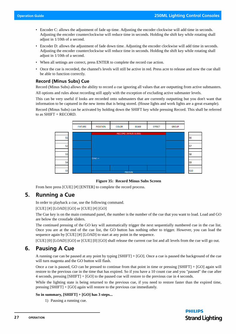
Record (Minus Subs) CueRecord (Minus Subs) allows the ability to record a cue ignoring all values that are outputting from active submasters.
All options and rules about recording still apply with the exception of excluding active submaster levels.
This can be very useful if looks are recorded onto submasters that are currently outputting but you don't want thatinformation to be captured in the new items that is being stored. (House lights and work lights are a great example).
Record (Minus Subs) can be activated by holding down the SHIFT key while pressing Record. This shall be referredto as SHIFT + RECORD.
Figure 35: Record Minus Subs Screen
From here press [CUE] [#] [ENTER] to complete the record process.
5. Running a CueIn order to playback a cue, use the following command.
[CUE] [#] [LOAD] [GO] or [CUE] [#] [GO]
The Cue key is on the main command panel, the number is the number of the cue that you want to load. Load and GOare below the crossfade sliders.
The continued pressing of the GO key will automatically trigger the next sequentially numbered cue in the cue list.Once you are at the end of the cue list, the GO button has nothing other to trigger. However, you can load thesequence again by [CUE] [#] [LOAD] to start at any point in the sequence.
[CUE] [0] [LOAD] [GO] or [CUE] [0] [GO] shall release the current cue list and all levels from the cue will go out.
6. Pausing A CueA running cue can be paused at any point by typing [SHIFT] + [GO]. Once a cue is paused the background of the cuewill turn magenta and the GO button will flash.
Once a cue is paused, GO can be pressed to continue from that point in time or pressing [SHIFT] + [GO] again willrestore to the previous cue in the time that has expired. So if you have a 10 count cue and you "paused" the cue after4 seconds, pressing [SHIFT] + [GO] to the paused cue will restore to the previous cue in 4 seconds.
While the lighting state is being returned to the previous cue, if you need to restore faster than the expired time,pressing [SHIFT] + [GO] again will restore to the previous cue immediately.
So in summary, [SHIFT] + [GO] has 3 steps...
1) Pausing a running cue.
27 OPERATION

250ML Lighting Control Consoles Operation Guide
2) Restoring to the previous cue in the time expired.
3) Restoring to the previous cue immediately.
7. Playback OperationCues can also be played back using the playback faders instead of the Load and Go buttons.
Once the cues have been stored, cycle the A/B faders (shown to the right) to zero. The playback faderswill be loaded when the first cues background color changes to cyan.
Once the first cue has been loaded onto the faders, take both faders to full. The cue will transition frombeginning to end corresponding to the movement of the faders from bottom to top. While the cue isfading, the cue's background color will be pink. When the cue is finished fading and outputting, thecue's background color will change to yellow and the next cue's background color will be cyan. Thatindicates that the cue is complete and the next cue is loaded.
Figure 36: Cue Running Graphic
The desk is now ready to transition to the second cue by crossfading the faders from top to bottom. The same colorchanges to the cue's background color will occur to acknowledge the loaded cyan, fading pink and completed yellowstates.
Figure 37: Cue Transitioning Graphic
8. Cue ListThe Cue List will allow the ability to view the list of cues as well as edit cue properties, preview cue content anddelete cues.
Start by pressing the CUE button on the command panel and the color screen will display the recorded cues as see inFigure 38.
Figure 38: Cue List
Playback Operation 28

Operation Guide 250ML Lighting Control Consoles
Figure 38 shows cues 1 and 2 in the list. The cue with the white background is the highlighted cue and shall respondto all softkey commands.
Note: Many command line commands may not be available when viewing the Cue List. It is recommended that you exit (press down on Encoder A) the Cue List for these commands.
Cue List Options
S1 - Edit Time:
This option allows the ability to edit times on the selected cue.
Figure 39: Cue List Options - Edit Time
• This screen allows the editing of attribute family timing, follow, fade up and fade down time.
• In addition, the ability to Preview the cue is available by pressing S9. If you change anything in the preview screen, just press Edit Time or List to save and restore to the previous screen.
S2-Copy Command:
The copy command allows the ability to copy cues. Press S2-Copy then the source cue number, then the @ key, thenthe target cue number. So to copy Cue 1 to Cue 21, type S2-Copy 1 @ 21 ENTER.
Ranges of cues can be copied using the THRU command, for example, S2-COPY CUE 1 THRU 5 @ 51 ENTER.This will copy cues 1 through 5 to 51 through 55.
Note: The destination cue number must be available before the copy procedure can be accomplished.
Figure 40: Copy Command - Copy Cue
S3-Move Command:
The Move command allows the ability to move cues. Press S3-Move then the source cue number, then the @ key,then the target cue number. So to move Cue 1 to Cue 21, type S3-Move 1 @ 21 ENTER.
Ranges of cues can be moved using the THRU command, for example, S3-MOVE CUE 1 THRU 5 @ 51 ENTER.This will moves cues 1 through 5 to 51 through 55.
29 OPERATION

250ML Lighting Control Consoles Operation Guide
Note: The destination cue number must be available before the move procedure can be accomplished.
Figure 41: Move Command - Move Cue
S6 - Delete All Cues:
Prior to using this function, make sure that there are no cues outputting by pressing GOTO 0 ENTER. This will allowthe delete all cues function to work.
S8 - Delete Cue:
Prior to using this function, make sure that there are no cues outputting by pressing GOTO 0 ENTER. This will allowthe delete cue function to work on the currently selected cue.
Use Encoder D to scroll down/up to select the appropriate cue.
S9-Preview:
Preview will allow the user to view the data of any cue without outputting the cue live. Once the cue is previewed,changes can be made by changing levels normally.
Once changes are made, press the LIST softkey to update and return to the Cue List.
S10 - Renumber All Cues:
This will renumber point cues to whole numbers in a numerically sequential order starting at 1.
9. Recording a SubmasterOnce the channels levels are at the desired levels, the first step is to place the desk into Record Mode. See “Channelsand Channel Levels” on page 23 for more information.
Figure 42: Recording a Submaster - Record Mode
Note: In Record Mode, many commands are limited to recording actions.
Record Mode Indication
Recording a Submaster 30

Operation Guide 250ML Lighting Control Consoles
Playback MasterThe Playback Master is simply a master for all faders. It will inhibit all submaster values, effect values and playbackvalues that are controlled by one of the 24 faders. All other output is not affected by the Playback Master. ThePlayback Master's level is displayed on the main monitor next to the Grand Master level.
Submaster PagesIn order to record levels to a submaster on a particular page, when the [RECORD] button is pressed, look for the pageindication on the two number LCD display. By default it will say 01. If another submaster page is desired, use theArrow Up and Arrow Down keys (as shown in Figure 43) to change pages and then complete the normal recordingprocedure.
Figure 43: Submaster Pages - LCD and Arrow Buttons
The next step after RECORD is pressed is to select a submaster by pressing its bump button. The selected submaster'sbump button will flash red to indicate that the active live channels are in the process of being stored into the selectedsubmaster. Figure 44 shows the options once the submaster has been selected by pressing its bump button.
Figure 44: Recording a Submaster - Record Mode Options
This screen gives the user the option to change the settings that are stored on the submaster. Most of these settingswill determine how the submaster outputs its stored data when activated. Let's go through the options starting with thesoftkeys.
Convention: When the text is in yellow, that indicates that there are other options.
Submaster Options
S1 - Bump:
This setting determines how the submaster's bump button will function. Pressing the S1 key shall change the bumpbutton's setting.
The options are:
• Off - the bump button shall not function.
• Flash - the button when held down shall send all channels to their stored value as long as the button is held down. When the button is released, the channels will restore to their previous level.
• Solo - the button when held down shall remove all other channel's levels and allow the channels that are stored in the selected sub to output based on the level of the submaster as long as the button is held down. When the button is released, all affected channels will restore to their previous levels.
• Latch - the button when pressed and released shall send all channels to their stored value and shall remain that way until the button is pressed again to release the channels to their previous level.
LCD Screen Arrow Up Arrow Down
Pile-On
31 OPERATION

250ML Lighting Control Consoles Operation Guide
• Flash + Solo - the button when held down shall send all channels to their stored values and remove all other chan-nel's levels as long as the button is held down. When the button is released, all affected channels will restore to their previous levels.
• Go/Run - the button shall be transformed into a GO button. This is effective when the submaster's levels have been stored as a Playback.
S2 - Color, S3 - Beamshape, and S4 - Position:
Color refers to all Color parameters, Beamshape refers to all beam related parameters and Position refers to pan / tiltand any other position related parameters.
• Snap - color, beam and position values shall output to their stored values in a zero time when the submaster is acti-vated.
• Fade Up - color, beam and position values shall output to their stored values in the fade up time when the submas-ter is activated.
• Fade Down - color, beam and position values shall release to their previous values in the fade down time when the submaster is reduced.
S5 - Type:
This selection refers to the different mode in which the submaster can be stored.
• Pile-On - this submaster shall function as a standard pile-on submaster. This is often referred to as HTP or Highest Takes Precedence.
• Chase - this submaster shall function as an effect chase. Multiple recordings of different effect steps are required for this to function properly.
• Playback - this submaster shall function as a playback. This allows multiple looks to be stored on this submaster and played back in order.
• Inhibitive - this submaster shall function as a master for the channels that have been stored within. Think of it as a grand master for user selected channels. An Inhibitive submaster's bump button shall be lit in white and will be marked with an "I" in the submaster display area of the monitor.
Note: Any Inhibitive submaster should normally be in the UP position. It will affect the output of all stored channel's levels if it is at any other value that full.
A good example is to put all of the Front of House (FOH) channels in this so that when you need to remove all FOHlight when the curtain comes in, you just pull the FOH Inhibitive submaster down.
• Exclusive - this submaster shall function as a sub whereby all stored values will output only from this submaster when active and will not be recorded. This is a great place to put channels that you don't want to be recorded into your cues. House lights and work lights are an example.
S6 - Del All Sub:
This setting allows the ability to delete all stored submasters as shown in Figure 45 on page 33.
Recording a Submaster 32

Operation Guide 250ML Lighting Control Consoles
WARNING! Once executed, this command cannot be reversed.
Figure 45: Delete All Submasters (Del All Sub) Screen
Note: The Delete All Submasters function only works on traditional submasters. It does not delete the submaster if a Chase or a Playback are stored on the fader. A Chase / Playback can be deleted through the Step List.
S7 - Del Page Sub:
This setting, as shown in Figure 46, allows the ability to delete all stored submasters from the current page.
WARNING! Once executed, this command cannot be reversed.
Figure 46: Delete All Subpages (Del Page Sub) Screen
S8 - Del Sub:
This setting allows the ability to delete the selected submaster. Note, the XX-XX indicates SubPage - Submaster.
33 OPERATION

250ML Lighting Control Consoles Operation Guide
WARNING! Once executed, this command cannot be reversed.
Figure 47: Deleting Selected Submaster (Del Sub) Screen.
S10 - Name:
This option allows the ability to label the submaster. Pressing (S10 - Name) shall bring up the following screen forlabeling.
Figure 48: Adding a Label (Name) to a Submaster
• Rotate Encoder D to identify the first letter for the label (Shift will allow for Upper Case letters) and press down on Encoder D to Select the highlighted letter. Repeat as necessary to add all letters to the label.
• Once the name is selected use Encoder D to select ENTER to complete the naming of the Submaster.
• The screen now returns to the Recording screen.
• Encoder C: allows the adjustment of fade up time. Reference Figure 44 on page 31 for the remaining encoder information.
• Adjusting the encoder clockwise will add time in seconds. Adjusting the encoder counterclockwise will reduce time in seconds. Holding the shift key will rotating shall adjust in 1/10th of a second.
• Encoder D: allows the adjustment of fade down time. Adjusting the encoder clockwise will add time in seconds. Adjusting the encoder counterclockwise will reduce time in seconds. Holding the shift key will rotating shall adjust in 1/10th of a second.
• When all settings are correct, press [ENTER] to complete the record sub action. An alternate method is to press and hold the submaster's bump button for 3 seconds to complete the record command.
• Once the submaster is recorded, the submaster's bump button will be lit in red and the channel's levels will still be active in red. Press [CLR] [CLR] to release and now the submaster shall function correctly.
Pile-On
Recording a Submaster 34

Operation Guide 250ML Lighting Control Consoles
When the channels have been released, take the submaster to full and confirm that the submaster was recorded asexpected as shown in Figure 49.
Figure 49: Recorded Channels to Full
Note: Not only will the channel's level display in amber but the sub listing will show the sub's level in the Step column and the submaster’s background will be in yellow.
10. Record (Minus Subs) SubmasterRecord (Minus Subs) allows the ability to record a submaster ignoring all values that are outputting from activesubmasters.
All options and rules about recording still apply with the exception of active submaster levels.
This can be very useful if looks are recorded onto submasters that are currently outputting but you don't want thatinformation to be captured in the new items that is being stored. (House lights and work lights are a great example).
Record (Minus Subs) can be activated by holding down the SHIFT key while pressing Record. This shall be referredto as SHIFT + RECORD.
Figure 50: Record Minus Subs Screen
From here, press the submaster bump button in which you want to record the console's output and then ENTER toconfirm (or you can press and hold the bump button for 3 seconds).
All Levels to Full (FL)
35 OPERATION

250ML Lighting Control Consoles Operation Guide
11. Recording a PlaybackOnce the channels levels are at the desired levels, the first step is to place the desk into Record Mode. See “Channelsand Channel Levels” on page 23 for more information.
Figure 51: Recording a Playback - Record Mode Screen
Note: In Record Mode, many commands are limited to recording actions.
The next step after RECORD is pressed is to select a submaster by pressing its bump button. The selected submaster'sbump button will flash red to indicate that the active live channels are in the process of being stored into the selectedsubmaster. The following screen shows the options once the submaster has been selected by pressing its bump button.
Figure 52: Changing the Settings of Stored Submaster
• This screen gives the user the option to change the settings that are stored on the submaster. Most of these settings will determine how the submaster outputs its stored data when activated.
• See "Submaster Options" on page 31 to go through all options available.
• To continue recording a Playback, as indicated in Figure 52, press (S5 - Type) twice to change the Type setting to Playback.
• When all settings are correct, press ENTER to complete the record sub action. An alternate method is to press and hold the submaster's bump button for 3 seconds to complete the record command.
• Once the submaster is recorded, the submaster's bump button will be lit in blue and the channel's levels will still be active in red. Press [CLR] [CLR] to release and now the submaster shall function correctly.
• At this point the playback submaster will function as a normal submaster simply because there is only one set of stored data. Repeat the process of setting levels and recording into the same submaster [RECORD][BUMP][ENTER] to store the second set of levels to the same submaster.
Pile-On
Recording a Playback 36

Operation Guide 250ML Lighting Control Consoles
Record Playback OptionsWhen the playback's bump button is pressed, the following playback screen will appear as shown in Figure 53.
Figure 53: Record Playback Options
S2 - Color, S3 - Beamshape, and S4 - Position:
Color refers to all Color parameters, Beamshape refers to all beam related parameters and Position refers to pan / tiltand any other position related parameters.
• Snap - color, beam and position values shall output to their stored values in a zero time when the cue is activated.
• Fade - color, beam and position values shall fade with the transition of the cue using the time of the cue.
• Snap@100% - color, beam and position values shall output to the stored values in a zero time when the cue is com-pleted.
S6 - Insert:
This option will store the current values and add a step prior to the existing step.
S7 - Delete:
This option will delete the selected playback. Once (S7) is pressed, this operation must be aborted or confirmed. Press(S9 - Exit) to abort or (S10 - Enter) to confirm.
WARNING! Once executed, this command cannot be reversed.
Encoder A - C - Step U/D (Current Step):
Notice that the Current Step indicator in the screen is one number higher than the total steps and there is an asterisk.This indicates that a new step will be added. By adjusting the Current Step encoder, the Current Step will change toone of the existing recorded steps and allow the ability to record over an existing step indicated by Current Step.Normally this encoder would not be adjusted and the current values will be added as a new step in the submasterplayback.
• Encoder B - Speed: this will adjust the rate at which the playback's step will wait prior to triggering the next step.
• Encoder C - Fade Up: this will adjust the rate at which the playback's step will fade up.
• Encoder D - Fade Down: this will adjust the rate at which the playback's step will fade down.
Note: Repeat this process for the number of looks that are required on that submaster playback.
12. Recording an EffectThis topic shall go over basic effect recording. Effects allow constant movement of light in either a step basedenvironment or in an effect engine based environment. The 250ML Control Console gives you the ability to do stepbased effects for intensity and engine based effects for automated luminaires.
Note: See “Now repeat this with Green (on the next Submaster), with Blue and then with other colors if these fixtures have more than 3 colors.” on page 54 for more information.
37 OPERATION

250ML Lighting Control Consoles Operation Guide
Once the channels levels are at the desired levels, the first step is to place the desk into Record Mode as shown inFigure 54.
Figure 54: Recording an Effect
Note: In Record Mode, many commands are limited to recording actions.
The next step after [RECORD] is pressed is to select a submaster by pressing its bump button. The selectedsubmaster's bump button will flash red to indicate that the active live channels are in the process of being stored intothe selected submaster. The following screen shows the options once the submaster has been selected by pressing itsbump button.
Figure 55: Changing the Settings of an Effect
• This screen gives the user the option to change the settings that are stored on the submaster. Most of these settings will determine how the submaster outputs its stored data when activated.
• See "Submaster Options" on page 31 to go through all options available.
• To continue recording an Effect, as indicated in Figure 55, press (S5 - Type) once to change the Type setting to Chase.
• When all settings are correct, press [ENTER] to complete the record sub action. An alternate method is to press and hold the submaster's bump button for 3 seconds to complete the record command.
• Once the submaster is recorded, the submaster's bump button will be lit in purple and the channel's levels will still be active in red. Press [CLR] [CLR] to release and now the submaster shall function correctly.
• At this point the playback submaster will function as a normal submaster simply because there is only one set of stored data. Repeat the process of setting levels and recording into the same submaster [RECORD][BUMP][ENTER] to store the second set of levels to the same submaster.
Pile-On
Recording an Effect 38

Operation Guide 250ML Lighting Control Consoles
Record Effect OptionsWhen the effect's bump button is pressed, the following effect screen will appear as shown in Figure 56.
Figure 56: Record Effect Options
S1 - Bump:
This option determines the submaster's bump button action.
• Off - bump button is disabled.
S2 - Color, S3 - Beamshape, and S4 - Position:
Color refers to all Color parameters, Beamshape refers to all beam related parameters and Position refers to pan / tiltand any other position related parameters.
• Snap - color, beam and position values shall output to their stored values in a zero time when the cue is activated.
• Fade - color, beam and position values shall fade with the transition of the cue using the time of the cue.
• Snap@100% - color, beam and position values shall output to the stored values in a zero time when the cue is com-pleted.
S5 - Direction:
This option determines the path in which the effect will run.
• Forward - runs in numerical order (1...2...3...).
• Backwards - runs in reverse numerical order (3...2...1...).
• Bounce - runs in numerical order then in reverse order (1...2...3...2...1...).
• Random - runs in a randomized order.
S6 - Insert:
This option will store the current values and add a step prior to the existing step.
S7 - Delete (Chase):
This setting will delete the selected effect. Once (S7) is pressed, this operation must be aborted or confirmed. Press(S9 - Exit) to abort or Press (S10 - Enter) to confirm.
WARNING! Once executed, this command cannot be reversed.
S8 - Delete (Step):
This setting will delete the selected step of the effect. Once (S7) is pressed, this operation must be aborted orconfirmed. Press (S9 - Exit) to abort or Press (S10 - Enter) to confirm.
WARNING! Once executed, this command cannot be reversed.
S10 - Name:
This option allows the ability to label the cue. Pressing (S10 - Name) shall bring up the naming screen for labeling.
39 OPERATION

250ML Lighting Control Consoles Operation Guide
Encoder A - C-Step U/D (Current Step):
Notice that the Current Step indicator in the screen is one number higher than the total steps and there is an asterisk.This indicates that a new step will be added. By adjusting the Current Step encoder, the Current Step will change toone of the existing recorded steps and allow the ability to record over an existing step indicated by Current Step.Normally this encoder would not be adjusted and the current values will be added as a new step in the submastereffect.
Encoder B - Speed:
This option will adjust the rate at which the effect's step will wait prior to triggering the next step.
Note: Repeat this process for the number of steps that are required on that submaster effect.
13. Cue/Submaster PreviewThe Cue/Submaster preview screen (Figure 57) is in a grey background to let you know you are in preview.
Figure 57: Cue/Submaster Preview Screen
• Level information is in the Intensity section for conventional and can be edited as needed.
• The Fixture section is for fixture data and below that will be unit’s data.
• To edit level information in preview, adjust the information via command line as you normally would.
Example: [1] [@] [5] [ENTER]
• This shall place channel 1 at 50%. If you want this information stored, just press the LIST softkey to store and return to the previous key.
• This screen also allows the editing of Cue Timing information. Just adjust via the Encoders and then press the LIST softkey to store the changes.
14. Submaster ListThe Submaster List is the point of information for all settings regarding data stored in faders. Remember that a fadercan be a submaster, playback or effect and all of its info can be seen and edited from the Submaster List.
Pressing [F2-Sub] will open up the Sub List on the color screen.
Cue/Submaster Preview 40

Operation Guide 250ML Lighting Control Consoles
Note: Helpful Hint: No matter which option is chosen from here, this (Figure 58) is the only screen from which you can exit the Submaster List and get back to the Main Screen.
Figure 58: Sub List Screen
The list will display everything you need to know about what is stored in the submasters. Let's discuss the columns ofinformation in the main window on the color screen.
• The No. column displays the sub page in the first set of numbers (01-) while the fader number is the second set of numbers (-01).
• The Step column displays how many steps are stored. S is for Submaster.
• Up displays the up time. This is often referred to as the "in" time.
• Dw displays the down time. This is often referred to as the "out" time.
• In the example above, Fader 1 is stored as a submaster as is fader 2. However, fader 7 has an effect stored on it with 2 steps. Purple text let's you know it's an effect. Fader 12 is stored as a playback with 3 steps. Blue text let's you know it's a playback.
• (S1 - Edit Time) will allow the editing of the submaster's parameters.
• For (S6-Delete Sub All), (S7-Delete Sub Page) and (S8-Delete Sub One), see "Submaster Options" on page 31 for more information.
• (S9-Step List): will display a list of all steps stored in a submaster effect or playback.
Editing a SubmasterOnce a fader is stored as a submaster, it can be edited without the need to recreate the look onstage and rerecord.
Here is a description of the S keys and their functions.
S1 - Edit
This will allow the editing of all parameters of the sub that was selected as well as editing the item in Preview.
Figure 59: Sub List Preview Screen
Note: After any item is changed, just press (S6-Sub List) to confirm the change. This will also return to the Sub List screen.
41 OPERATION

250ML Lighting Control Consoles Operation Guide
• (S1 - Bump): changes how the bump button functions. Options are Off, Flash, Solo, Latch, Flash+Solo, and Go/Run. See Submaster Options for more information.
• (S2 - S4: Color, Beam and Position): changes how the attribute family plays back when activated. Options are Snap, Fade Up and Fade Down. See "Submaster Options" on page 31 for more information.
• (S6 - Sub List): This button functions as both the [ENTER] key for accepting changes and returns the screen to the main Sub List screen options.
• (S9 - Preview): Allows previewing and editing the content of the submaster. See "Cue/Submaster Preview" on page 40 for more info.
While in Sub Preview, the monitor will appear with a grey background. That's the indication that you are in preview.Editing can be done at this point. A simple example of editing levels while in preview:
[CHANNEL] [ON] [S9-LIST]
After the channels' levels have been changed, pressing (S9-List) is the equivalent to the [ENTER] key to update theitem.
Figure 60: Sub Preview Screen
Encoder C/D - Fade Up / Fade Down: rotating the encoder to change the fade up / down times. Press (S9-List) toaccept the edits.
Editing a Submaster EffectOnce an effect is stored as a submaster, it can be edited without the need to recreate the look onstage and rerecord.
Here is a description of the S keys and their functions.
Figure 61: Editing a Submaster Effect
• (S1 - Edit Time): This will allow the editing of all parameters of the submaster effect that was selected as well as editing the item in Preview.
• (S2 - Sub List): will restore the screen back to the Sub List.
• (S7 - Delete All Steps): will delete all steps of the effect.
• (S8 - Delete Step): Will delete the highlighted step of the effect.
• (S9 - Preview): will show the content of the step in blind where it can be edited. Just press (S9-List) to confirm the changes to the effect step once they are made.
Submaster List 42

Operation Guide 250ML Lighting Control Consoles
• Encoder D - use the Up/Down action to highlight the effect step that is to be affected.
Edit a Submaster PlaybackOnce a playback is stored as a submaster, it can be edited without the need to recreate the look onstage and rerecord.
Figure 62: Edit a Submaster Playback
• (S1 - Edit Time): This will allow the editing of all parameters of the submaster effect that was selected as well as editing the item in Preview.
• (S2 - Sub List): will restore the screen back to the Sub List.
• (S7 - Delete All Steps): will delete all steps of the effect.
• (S8 - Delete Step): Will delete the highlighted step of the effect.
• (S9 - Preview): will show the content of the step in blind where it can be edited. Just press S9-List to confirm the changes to the effect step once they are made.
• Encoder D - use the Up/Down action to highlight the effect step that is to be affected.
Submaster Pages and PagingThe 250ML Lighting Control Console has 24 submasters and 24 pages of submasters. In orderto change pages, press the F2-Sub key. That will activate the LED display and its related arrowbuttons for paging. The Up button pages to the next higher page, the Down button pages to thenext lower page. Once page 24 is selected, paging up again will cycle back to page 1. LED Display
Up Arrow Button
Down Arrow Button
43 OPERATION

250ML Lighting Control Consoles Operation Guide
15. FX ListThe effects list is the point of information for all effects that are actively running based on fader output. Pressing [F1– FX] will open the FX List on the color screen.
Figure 63: FX List Screen
Figure 63 shows 2 effects that are running based upon the faders with the effects being active. The No. shows thepage and fader number, the Step shows the active step. The Name shows the labeled name of the effect. Direct is thedirection in which the effect is running. Speed is the rate at which the effect is running and Status will be Active forany running effect.
This effect screen shall allow the user to manipulate effects. Use Encoder D to highlight any active effect. Clockwisewill go down the list highlighting each effect with a white background bar. Counterclockwise will go up the list. PressEncoder D to Select. Now that the desired effect is selected. S1-S4 will adjust the effect's direction.
• S6-Run will Run the effect using the recorded time.
• S9-GO - will trigger a GO of the next step allowing manual control of each steps' advance.
• S10-Pause - will freeze the effect from advancing.
16. Recording a GroupA Group is a collection of fixtures only (not channels) used by programmers to speedup the act of assigning levels to fixtures. The first step is to select the fixtures that youwant stored in the group Select FIXTURE button and then (S1) through (S10).
Then press [RECORD] [GROUP] and the appropriate softkey. The first group willlikely be assigned to S1 but any softkey is available.
Figure 64: Recording a Group
Select Encoder A to bring up the naming screen to label a group.
17. Applying GroupsOnce the Groups are recorded, simply press the [GROUP] key and this will bring up the recorded group screen. Anysoftkey that has a group assigned to it will be lit in red. Simply press the appropriate S key and you will immediatelygo to the Fixture screen with the Group's Fixtures selected.
FX List 44

Operation Guide 250ML Lighting Control Consoles
18. Basic Automated Luminaire ControlBasic automated luminaire control starts by understanding the premise that channels are for dimmer control andaccessed through the numeric keypad; while fixtures are for automated luminaires (moving lights, LEDs and otherdevices) and are accessed through the color screen and their surrounding buttons.
Once a moving light is properly patched, fixtures can be accessed by pressing the FIXTURE button.
The patched fixtures shall appear on the S keys. By selecting a fixture, the appropriate S key shall flash.Multiple fixtures can be manipulated at the same time by selecting multiple S keys. Multiple S keys willbe lit red if they are active although only one will flash. The flashing fixture shall be the one displayed onthe monitor even though the other selected fixtures are being affected.
The LCD screen shall identify the fixture page. Page 1 shall access fixtures 1 thru 10. Page 2 shall access fixtures 11thru 20 and page 3 shall access fixtures 21 thru 30. Use the Arrow Up and Arrow Down keys next to the LCD screento change fixture pages.
Basic attributes like Intensity shall appear on the color screen and are accessed from Encoders A thru D.
Figure 65: Automated Luminaire Control
Engaging the encoder shall change the values for the selected attribute. When the attribute's value has been changed,the background shall change to white and the numbers shall advance.
HomeThe HOME button shall take the selected fixtures attributes back to their default position and deselect theattributes.
In addition to Homing the entire fixture, by pressing HOME + any attribute family key, only that attributefamilies attributes will be sent to their default position. For example, pressing HOME + POSITION willdefault only the position attributes of Pan and Tilt. (in some cases, Position Time may be assigned to the Positionfamily. In this case, Position Time would be defaulted as well.)
• HOME + COLOR will default all color parameters.
• HOME + BEAM will default all beam parameters.
• [SHIFT] = HOME: release all fixture attributes to default value.
Fixture Intensity ControlExample: Select the first fixture by pressing (S1) button. If this fixture has intensity, that will be available on EncoderA sitting in its default value unchanged.
Figure 66: Intensity Control
45 OPERATION

250ML Lighting Control Consoles Operation Guide
Now adjust Encoder A and the intensities value shall change plus the background has changed to white. Thisindicates that the value has been changed.
Figure 67: Intensity Control (Value Change)
When recorded, this value will be stored in the fader or the cue.
Figure 68: Fixture Display - Patched Fixture Attributes
The fixture area display shall show all fixtures that are patched. Figure 68 shows 3 fixtures, each with 7 attributes.Should there be more than 7 attributes, the attribute blocks will wrap around to the second line.
• Fixtures that are selected with have the fixture block in red.
• Fixtures that were adjusted but are no longer selected have the fixture block text in red.
Attributes that have been adjusted will appear in a red box. Adjusting Pan will also select Tilt. Some attribute familieswill work collectively (selecting all parameters for the selected attribute family, some will work independently. Thiswill depend upon the family and the fixture.)
Stored parameter values that have been changed in the current cue will appear in blue. Values that have changed in adifferent cue will appear in magenta. Values that have not been changed shall remain in white.
Paging the Fixture DisplayWhen the FIXTURE key is selected, the plus "+" key will "page" the fixture display. This will page patched fixturesin numerical order from fixtures 1 thru 30, based upon the number of fixtures and attributes that fully populates theset fixture area. There is space for 4 fixtures if all attributes fit on the same horizontal line.
Tagging and UntaggingWith Fixtures that are patched, adjusting any parameter will "tag" that parameter. A tagged parameter will appear onthe color screen in a white background. On the monitor, the parameter will appear in a red background.
If in Setup, the Record Mode is at the default setting of "Full", recording an attributed fixture shall record all changesbased upon the tagging even if the values are at zero.
• Tagging of a fixture occurs when the parameter has been changed. (On Monitor: Red background, white text)
• Untagging of a fixture occurs to change the fixture to no longer be selected.
Several things can be untagged:
• All Fixtures can be untagged by [UNTAG] + [FIXTURE]
• Individual Fixtures can be untagged by [UNTAG] + [S1/S10]
• Attribute Families can be untagged by [UNTAG] + [POSITION / COLOR / BEAM]
• Individual Attributes can be untagged by [UNTAG] + [Encoder A / B / C / D] when the Encoders are populated with the desired attributes.
If the Record Mode is not default and is set to "Channel", then only the tagged values shall be recorded and values atzero will be ignored.
Basic Automated Luminaire Control 46

Operation Guide 250ML Lighting Control Consoles
This allows you to decide if a attributes recorded onto submasters should be absolute. (record mode should be set to"Full") or if the recorded colors should be able to mix with each other (not absolute), (record mode for color shouldbe set to "Channel".)
19. Advanced Automated Luminaire ControlWith any combination of MLs selected, press SHIFT + FIXTURE to reveal some advanced functionality to the MLcontrol.
Figure 69: Advanced Automated Luminaire Control - SHIFT + FIXTURE
• S1/S2 will allow the user to select their preferred method of intensity control. Absolute for traditional level control of percentage or Relative to allow relative adjustment of the fixture.
• The S6-S9 Fan commands will allow the user to "fan" values across the selected parameter in the following config-urations.
S6-Fan FirstWill hold the first fixture's value at the existing level and range values across all selected fixtures with the last fixturegetting the biggest change.
S7-Fan MiddleWill hold the center fixture's existing level and range values in both directions however the first fixture's values willgo in the opposite direction as the last. Therefore, if 5 fixtures are selected. 3 will hold it's values, 2 will be the samedistance from center as 4 but in the opposite direction. 1 will be the same distance from center as 5 but in the oppositedirection.
S8-Fan LastWill hold the last fixture's value at the existing level and range values across all selected fixtures with the first fixturegetting the biggest change.
S9-Fan VWill hold the center fixture's existing level and range values equally in both directions (toward the first selectedfixture and the last selected fixture) with the first and last fixtures getting the biggest change. Therefore, if 5 fixturesare selected, the 1 and 5 will have the same values, 2 and 4 will have the same and 3 will remain constant.
Shift + (Attribute Family)Shift + Position/Color/Beam will give the user all Shift + Fixture options on each attribute family. So the Fanfunctionality will apply to attributes.
20. PalettesPalettes store specific attributes data for recall and storing into faders and cues. There are many reasons to use apalette over storing raw numerical data.
• You can name a palette. Seeing a moving light in Pan/Tilt "P:02" or "Chair" instead of Pan 038 and Tilt 185 can be more user friendly.
• Palettes can be reused multiple times. The previously mentioned "P:02" position palette can then be accessed for storage in different faders and cues.
47 OPERATION

250ML Lighting Control Consoles Operation Guide
• If the data in a palette gets changed or updated, then all of the faders and cues are automatically updated.
Recording a PaletteThe process of recording a palette allows the storage of position, color and beam information into an easily accessiblestate.
The following is the process to record a palette:
Adjust the parameters that are to be stored. The parameter's data will appear in a white box.
Figure 70: Recording a Palette
Note: This screen shot shows the typical parameters of pan and tilt. If you are using color mixing fixtures and recording color or beam parameters, the attributes will be different.
Press the [RECORD] key. Then press the proper attribute family button (position, color or beam) above the colorscreen. Then press any unpopulated S key to assign the palette to that button. The screen shot below show recordingposition as an example.
Figure 71: Recording a Palette - Position Example
Use Encoder A to assign a Name to the palette. (Note, this step is optional.)To complete the recording process, press [ENTER]
The recording position(s) will now appear and be accessed by the S keys.
Applying A PaletteOnce palettes have been recorded, they can be access and applied by first selected the fixture(s).
Pressing FIXTURE then S1 key or any combination of the S keys to select the appropriate fixtures.
Now select the appropriate attribute family. Example, press the POSITION key.
Then select the appropriate S key to access the desired palette. The image below shows that two positionpalettes have been stored. Position 1 has no name, while Position 2 has been labeled "Chair". Thefixture(s) have been placed in Position 1 by pressing S1 key.
Palettes 48

Operation Guide 250ML Lighting Control Consoles
Figure 72: Applying a Palette
Once the palette has been applied and all output is correct, the fixture can be stored into a fader or cue.
Accessing Fixtures using Channel NumbersAll fixtures shall display a 900 series number as the softkeys label on the color screen. This is a channel alias andshall allow access of the fixture from the numerical keypad. For example, the first fixture patched will have a channelalias of 901. From the Command Line, press [9] [0] [1] [ENTER]. This shall have the same effect as selecting the S1softkey.
21. FocusThe Focus button, [F2], is the point of information for all focus positions that are recorded in the current showfile.Each type of focus point (Position, Color and Beam) are available and can be manipulated here.
Figure 73: Focus List Screen
Use Encoder D to move up and down the focus list. The selected type of focus point will be highlighted in the whitebackground bar. Press (S9-Show List) to see the list of each type or Encoder A - Exit to return to the previous screen.
49 OPERATION

250ML Lighting Control Consoles Operation Guide
S9-Show ListThis will display all focuses that have been stored of the type selected.
Figure 74: Preview Position Focus Screen
This example shows the 2 focus positions that have been stored. The first one without a name, the second one hasbeen labeled “Chair”.
• Encoder D – Up/Down will allow the user to select any focus by rotating the encoder. (S6-Focus List) shall take the user back to the list of focus types.
• (S7-Delete All) allows the user to delete all stored focus points. A warning screen shall allow the user to select (S9-Yes) or (S10-No).
WARNING! Once executed, this command cannot be reversed.
• (S8-Delete Focus) allows the user to delete the highlighted focus point. A warning screen shall allow the user to select (S9-Yes) or (S10-No).
WARNING! Once executed, this command cannot be reversed.
• (S9-Preview) allows the user to preview the highlighted focus point. The VGA monitor will display the stored focus information to be viewed.
• (S10-Name) allows the user to label the focus point.
22. Automated Luminaire EffectsEffects allow constant movement of light in either a step based environment or in an effect engine based environment.The 250ML Control Console gives you the ability to do step based affects for intensity and engine based effects forautomated luminaires.
The moving light effects engine can be applied to the movement parameters of any patched moving light.This will give you the ability to select from available prebuilt effects, change the size on both axis, speedand direction.
The effect engine shall be accessed by the Effect button once the fixtures have been selected.
Automated Luminaire Effects 50

Operation Guide 250ML Lighting Control Consoles
Start by pressing the FIXTURE button and then selecting the appropriate S keys for the fixtures that you want theeffect to apply to. Then press the EFFECT button to present the effect's options on the color screen.
Figure 75: Set Fixture Effect Status
• (S1) thru (S5) preset the prebuilt effect options. (S1 - None), (S2 - Ellipse) or an Oval, (S3 - Figure 8) or a Bally-hoo, (S4 - Quad) or Square, and (S5 - Triangle). The effect that is selected will appear in yellow text.
• (S6 - Direction): determines the direction of the movement. Options are Clockwise and Counterclockwise.
• Encoder B - Size X: determines the scale of the movement on the X axis.
• Encoder C - Size Y: determines the scale of the movement on the Y axis.
• Encoder D - Speed: determines the speed at which the effect operates.
23. ArchiveThe Archive screen in Setup allows many utility actions to occur.
Figure 76: Archive Menu
Save ShowThis will allow the saving of the showfile onto a USB key.
Figure 77: Save Show Menu
Using Encoder D, scroll up/down to highlight Save Show and press down on Encoder D to select.
51 OPERATION
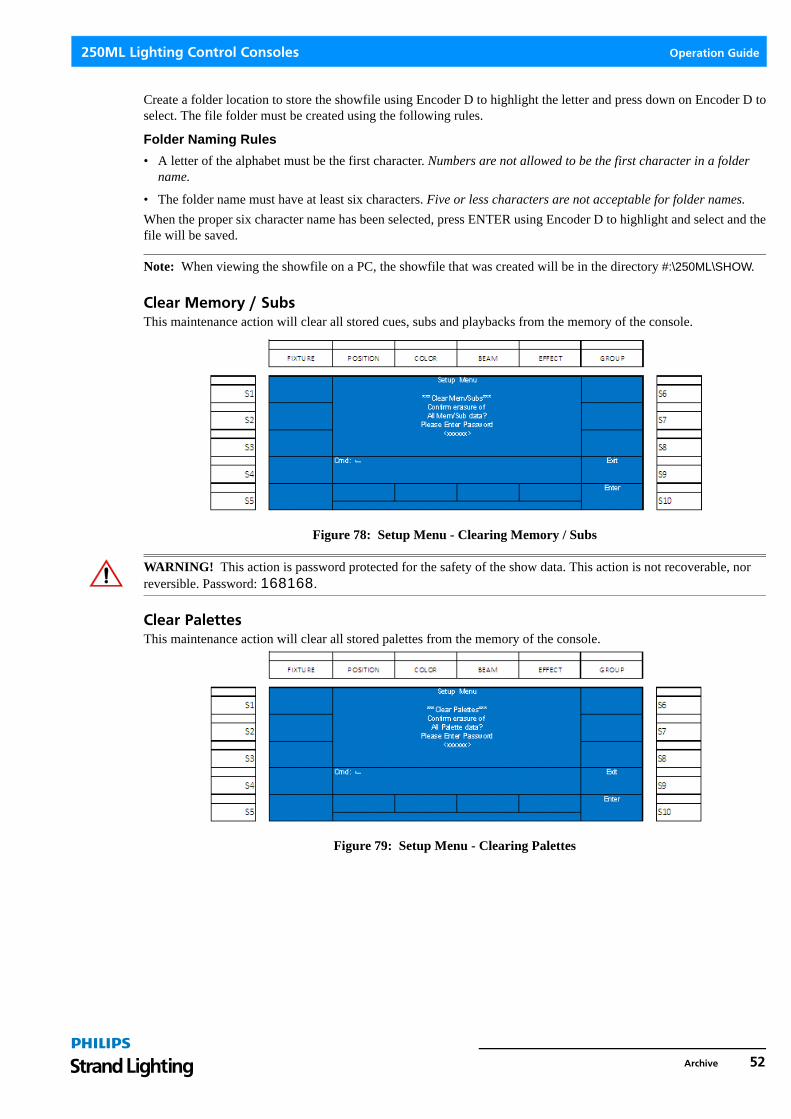
250ML Lighting Control Consoles Operation Guide
Create a folder location to store the showfile using Encoder D to highlight the letter and press down on Encoder D toselect. The file folder must be created using the following rules.
Folder Naming Rules
• A letter of the alphabet must be the first character. Numbers are not allowed to be the first character in a folder name.
• The folder name must have at least six characters. Five or less characters are not acceptable for folder names.When the proper six character name has been selected, press ENTER using Encoder D to highlight and select and thefile will be saved.
Note: When viewing the showfile on a PC, the showfile that was created will be in the directory #:\250ML\SHOW.
Clear Memory / SubsThis maintenance action will clear all stored cues, subs and playbacks from the memory of the console.
Figure 78: Setup Menu - Clearing Memory / Subs
WARNING! This action is password protected for the safety of the show data. This action is not recoverable, nor reversible. Password: 168168.
Clear PalettesThis maintenance action will clear all stored palettes from the memory of the console.
Figure 79: Setup Menu - Clearing Palettes
Archive 52

Operation Guide 250ML Lighting Control Consoles
WARNING! This action is password protected for the safety of the show data. This action is not recoverable, nor reversible. Password: 168168.
Default SetupThis maintenance action shall default all of the setup options for the 250ML Control Console.
Figure 80: Setup Menu - Resetting to Default Setup
WARNING! This action is password protected for the safety of the show data. This action is not recoverable, nor reversible. Password: 168168.
Load ShowThis maintenance action allows the loading of a previously stored showfile.
Figure 81: Loading a Showfile
Using Encoder D, scroll up/down to highlight the show to load and select (S10 - Enter) to confirm the showfile.
Figure 82: Showfile Loading
With the softkeys, the user can select which items within the showfile will be loaded. All selected items shall have theappropriate softkey lit in red. Press [Encoder D - Enter] when the selection settings are correct.
While the showfile is loading, progress will be reported in the center of the color screen.
53 OPERATION

250ML Lighting Control Consoles Operation Guide
Once a showfile is selected to load, it replaces the showfile that currently exists in the memory of the console. If youneed to keep the existing showfile, save it prior to loading a different showfile.
24. Storing Color Mixing Fixtures on Submasters TutorialThe 250ML has different settings that allow for color mixing fixtures such as LEDs to be stored differently dependingupon the desired outcome.
For Storing All LED Parameters on a SubmasterIf the goal is to mix an RGB fixture and have the submaster go to that mixed color every time, make sure the 250MLsRecord Mode is set to Full. (See "Record Options" on page 10). Select the Fixtures, then the Color family and set thecolors using the encoders. Notice that when one color is changed, all colors are in a red box. This indicates that allcolor parameters now have a value (even if it's just zero). When the LEDs are outputting the right color, record thesubmaster. (See "Recording a Submaster" on page 30).
Once recorded, Home all Fixtures by pressing the Home key. This will default all selected fixtures' parameters.
Now repeat from the beginning to store the next submaster with LED values.
You can either include intensity in these submasters or record intensities in a separate submaster.
To record intensities into a separate submaster, select all desired LEDs, with the Fixture key selected, Encoder A willadjust intensity. When ready, Record the Submaster (See "Recording a Submaster" on page 30) and then Home allfixtures prior to recording the next submaster.
For Storing Changed LED Parameters on a SubmasterIf the goal is to use submasters as mixing tools for an LED, make sure the 250ML console’s Record Mode is set toChannel. (See "Record Options" on page 10). This will ensure that only the changed parameter is marked forrecording. Select the Fixtures, then the Color family and set the first color (likely Red) to full or 255. Notice thatwhen one color is changed (red box), the other colors are not changed. With Red at full, record the submaster (See"Recording a Submaster" on page 30).
Once recorded, Home all Fixtures by pressing the Home key. This will default all selected fixtures' parameters.
Now repeat this with Green (on the next Submaster), with Blue and then with other colors if these fixtures have morethan 3 colors.
25. Effects TutorialEffects allow constant movement of light in either a step based environment or in an effect engine based environment.The 250ML Control Console gives you the ability to do step based affects for intensity and engine based effects forautomated luminaires.
Creating an Intensity EffectIn order to use an intensity based effect, the console must have intensity values stored into multiple steps. These stepsshall be stored on a fader. Start by setting levels, storing the effect on a submaster, releasing the channels then repeatthis process until all steps are recorded.
Here is a key to the images in the example…
This image (Figure 83) represents the smaller buttons on the console. These are bump buttons and softkeys.
Figure 83: Small Button on Console
Storing Color Mixing Fixtures on Submasters Tutorial 54

Operation Guide 250ML Lighting Control Consoles
This image (Figure 83) represents the larger buttons on the console. These are the command line keys.
Figure 84: Large Button on Console
Here is an example…
Set levels by pressing.
Store the first step to Submaster 1 as follows:
Figure 85 is what is displayed after the RECORD key and Sub 1's bump button is pressed. Pressing (S5) shall changethe type from "Normal" to "Chase" prior to pressing [ENTER]. This is when it is recommend to change the Fade Up /Down times for the intensities in this step.
Figure 85: Creating Intensity Effects - Recording to Submaster 1
Note: When the submaster is stored with an effect, the bump button shall be lit purple.
Finish by clearing out the adjusted channels as follows:
Repeat level adjustment as follows:
Store the second step to Submaster 1 as follows:
Pile-On
55 OPERATION

250ML Lighting Control Consoles Operation Guide
Figure 86: Record Step Chase
Since the info in Submaster 1 has already been designated as an effect, that step doesn't need to be repeated. HoweverTotal Step will display as 01 and Current Step as 02. If you want the default of the current step adding to the end ofthe step list, then no adjustment is needed. However if you need the step that you are recording to be in front of thecurrently recorded step 1, then adjust the C-Step U/D option on Encoder A. Also, this is a good time to adjust theSpeed of the effect. For this example, please leave the Current Step set to 02.
Finish by clearing out the adjusted channels as follows:
Repeat level adjustment as follows:
Store the third step to Submaster 1 as follows:
Just move the submaster's fader to full to see the effect run.
Effects Tutorial 56

Operation Guide 250ML Lighting Control Consoles
MAINTENANCE
The Maintenance section provides tools for resetting, testing and upgrading the 250ML Control Console.
Figure 87: Maintenance Menu Screen
WARNING! The items described in this section are password protected for the safety of the show data. These actions, once executed, are not recoverable, nor reversible. Should you have questions regarding executing any of the maintenance items in this section, please consult your Philips Selecon dealer or technical support.
1. Reset DeskThis shall remove all show data and default the console back to its original settings.
Figure 88: Maintenance Screen - Reset Desk Option
WARNING! This action is password protected for the safety of the show data. This action is not recoverable, nor reversible. Password: 168168.
2. Update SoftwareThis shall allow the user to update the operational software of the 250ML Control Console. Please download thelatest version of the 250ML software from www.strandlighting.com. Insert the USB key with the software into theUSB port on the top of the console.
Note: Do not use the port on the back plate of the desk as this is reserved for a USB light.
57 MAINTENANCE

250ML Lighting Control Consoles Operation Guide
Use Encoder D to navigate to the Update Software option and press to select.
Figure 89: Setup Menu - Software Update Screen
WARNING! This action is password protected for the safety of the show data. This action is not recoverable, nor reversible. Password: 168168.
3. Update VGA ScreenThis shall allow the user to update the video output software of the 250ML Control Console. Please download thelatest version of the 250ML software from www.strandlighting.com. Insert the USB key with the software into theUSB port on the top of the console. Do not use the port on the back plate of the desk as this is reserved for a USBlight.
Use Encoder D to navigate to the Update VGA Screen option and press to select.
Figure 90: Setup Menu - Update VGA Screen
WARNING! This action is password protected for the safety of the show data. This action is not recoverable, nor reversible. Password: 168168.
Update VGA Screen 58
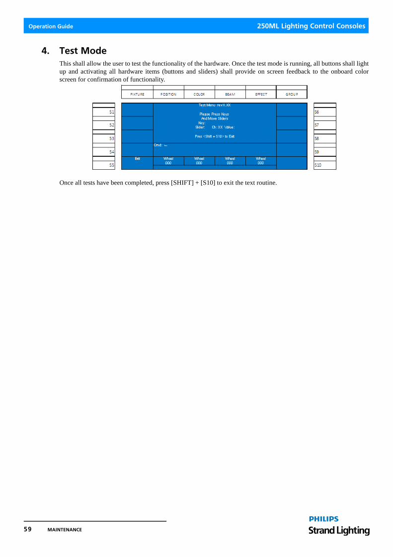
Operation Guide 250ML Lighting Control Consoles
4. Test ModeThis shall allow the user to test the functionality of the hardware. Once the test mode is running, all buttons shall lightup and activating all hardware items (buttons and sliders) shall provide on screen feedback to the onboard colorscreen for confirmation of functionality.
Once all tests have been completed, press [SHIFT] + [S10] to exit the text routine.
59 MAINTENANCE

250ML Lighting Control Consoles Operation Guide
PRODUCT INFORMATION
1. SpecificationModel: Strand Lighting 250ML Control Console
On-Board LCD: 60x128 dot, TFT LCD with contrast adjustment
Inputs/Outputs: DMX IN: DMX512A XLR5M Port
DMX OUT: 2 Each DMX512A XLR5F Ports
Power Input: Connects to a Universal Power Supply (100-240VAC to VDC, provided with unit)
Power Requirement: DC 9~12V 2A Max
USB Ports: 2 Ports (Front USB port for library storage, rear USB port is specifically for desk light
connection).
Overall Dimensions: 28.9 x 12.8 x 3.2 in / 734 x 324 x 81 mm
Weight: 19.4 lbs (8.8 kgs)
Housing: Electrolytic Plate with powder finishing
734 mm / 28.9 in 80.1 mm /3.2 in
324 mm /12.8 in
29 mm /1.1 in
Specification 60

Operation Guide 250ML Lighting Control Consoles
2. Console CapacitiesThe following capacities are available on your 250ML control console.
• 250 Conventional Dimmer Channels
• 30 Multiple Parameter Fixtures with a maximum of 40 parameters for each fixture
• 999 Cues
• 24 Faders with 24 pages of faders
• Each fader can be either a submaster, effect or playback
• 99 Effects with up to 99 steps in each effect
• The Fixture Library can accommodate more than 3000 fixtures
3. Principle Features
• Professional DMX512 console, ideal for conventional lights, simple moving light control and LED fixture control.
• Versatile, powerful, and offering 250 intensity channels and 30 automated luminaire of control via 1024 DMX out-puts.
• LCD display for easy operation with contrast adjustment.
• Monitor display to provide enhanced display of information.
• USB port for uploading/downloading data or updating software.
• Ethernet port for faster communication with compatible devices.
• DMX IN allows 5 pin XLR connector to connect external console.
• DMX output 5 pin XLR connector.
• Back lighting bump buttons changes color depending on their operational status.
• Grand Master fader for total output control.
• 24 Submasters with 24 Pages
• Integrated Moving Light Control with LCD screen, 10 softkeys and 4 encoders.
• Faders can be either submasters, playbacks or effects.
• Cue Playback with A/B faders and Load / Go buttons.
• MIDI In/Thru
• Intuitive Effects Engine
• Traditional Command Line Entry
• Blackout button enables the user to snap all fixtures to off.
• Integrated video card (VGA) allows for 800 x 600 monitor output (monitor sold separately).
61 PRODUCT INFORMATION

250ML Lighting Control Consoles Operation Guide
Notes
Principle Features 62