for - CANDU Owners Group Library/20044607.pdf · 2011-09-16 · SDS2). Inthis sense, their ......
28
Design of CANDU Reaetors 70 SECTION 6 Desigo of Reactivity Control Units (RCUs) 6.1 FWlCtionai Description of Reactivity Control Units (RCUs) Reactivity Control Units (RCUs) form the in--£eactor sensing and actuating portions of the Reactor Regulating System (RRS) and the two reactor safety Shut-Down Systems (SDS1 and SDS2). In this sense, their reactor control and safety functions can best be descn"bed collectively, as functional parts of those systems. Similarly, because all RCUs are physically parts of the reactor assembly, they share many common features of design and construction. The following sections describe these common aspects for the RCUs, and later sections give detailed descriptions of the unique aspects and construction of each device. The reactor complement of reactivity control units is comprised of devices which serve one of three functions for these systems: a) those which measure the fission power levels: Vertical F111X Detector Units (VFD) Horizontal F111X Detector Units (HFD) Ion Chamber Units (IC) b) those which regulate power levels: Adjuster Rod Units (ADJ) Liquid Zone Control Units (IZC) Mechanical Control Absorber Units (MCA) c) those which shut dovm the reactor in an emergency: Shutoff Rod Units (SOR) Liquid Injection Shutdown Units (LIS) & (LISS) Their system relationships are displayed in Figure 6-1. In CANDU reactors, RCUs serving as emergency shutdown devices are entirely independent of those used for reactor power regulation. Furthermore, two complete and diverse shutdown systems are provided, each having full shutdown capability, independent of the other. Because of the wide lattice spacing of the fuel channels in a CANDU core, and because fuel is
Transcript of for - CANDU Owners Group Library/20044607.pdf · 2011-09-16 · SDS2). Inthis sense, their ......

Design ofCANDU Reaetors 70
SECTION 6 Desigo of Reactivity Control Units (RCUs)
6.1 FWlCtionai Description ofReactivity Control Units (RCUs)
Reactivity Control Units (RCUs) form the in--£eactor sensing and actuating portions oftheReactor Regulating System (RRS) and the two reactor safety Shut-Down Systems (SDS1 andSDS2). In this sense, their reactor control and safety functions can best be descn"bed collectively,as functional parts ofthose systems. Similarly, because all RCUs are physically parts ofthereactor assembly, they share many common features ofdesign and construction. The followingsections describe these common aspects for the RCUs, and later sections give detaileddescriptions ofthe unique aspects and construction ofeach device.
The reactor complement ofreactivity control units is comprised ofdevices which serve one ofthree functions for these systems:
a) those which measure the fission power levels:
Vertical F111X Detector Units (VFD)
Horizontal F111X Detector Units (HFD)
Ion Chamber Units (IC)
b) those which regulate power levels:
Adjuster Rod Units (ADJ)
Liquid Zone Control Units (IZC)
Mechanical Control Absorber Units (MCA)
c) those which shut dovm the reactor in an emergency:
ShutoffRod Units (SOR)
Liquid Injection Shutdown Units (LIS) & (LISS)
Their system relationships are displayed in Figure 6-1.
In CANDU reactors, RCUs serving as emergency shutdown devices are entirely independent ofthose used for reactor power regulation. Furthermore, two complete and diverse shutdownsystems are provided, each having full shutdown capability, independent ofthe other.
Because ofthe wide lattice spacing ofthe fuel channels in a CANDU core, and because fuel is

Proprietary Doe_t Design ofCANDU Reactors 71
continually being changed in individual fuel channels while it operates, the power level in the coreis subject to both general and local variations. Furthermore, both ofthese changes can havesteady rates ofchange and periodic fluctuations. Accordingly, a relatively large number ofbothmeasuring and actuating devices are used in a CANDU, and they are distributed throughout thecore. FurthermOre, several different kinds ofdevices are used. These devices are ofessentiallythe same design in all current CANDUs, and are considered generic designs, changed only inlength and quantity to suit the different core sizes. Overview descriptions for these devices aregiven below, for a CANDU 6 reactor. Detai1 descriptions are given in subsequent sections.
The quantities and locations ofthe RCUs used in a CA.JlIDU 6 are shown on Figures 6-2, 6-3, 6-4&6-5.
All RCUs serving the Reactor Regulating System (RRS) and ShutDown System One (SDSI) arevertically oriented (except for the ion chamber units), with connector and actuator housingsmounted on the Reactivity Mechanisms Deck (RMD). All their sensing or absorbing elemerr.s arepositioned inside guide tubes immersed in the moderator, between the rows ofcalandria tubes.The housings communicate with the in--core components through thimble tubes which extend thecalandria vessel boundary up through the reactivity mechanisms deck. Ion chambers servingSDSI and RRS are located on the outside ofthe B side ofthe calandria, with their housingsoutside the vault wall. Only RCUs associated with Shutdown System Two (SDS2) are mountedon the D side ofthe reactor, and all SDS2 RCUs are mounted there. In this way, all RCUs forSDS2 are physically separated from those used for SDSI. This ensures the two systems cannotbe disabled by the same physical accident, such as a fire, missile or steam line break.
6.1.1 Power Measuring RCUs
Overall power levels and rates ofchange are measured by ion chamber instruments mounted onthe outside ofthe calandria sbell sides. Local power levels are measured by flux detectorelements distributed throughout the core.
6.1.1.1 Ion Chamber Units (JCUs)
Overall fission power level is measured by ion chambers in six horizontal housing units, mountedon the outside ofthe caJandria vessel. See Figure 6-2.
In each ofthree housings on the reactor B side, separate instruments serve the RRS andSDSlsystems, while an instrument in each ofthe three D side housings serve only SDS2. The ionchamber instruments provide electrical signals proportionate to the general fission power level inthat region. See Figure 6-6.
A shutter is included in each housing, which is a movable mass ofneutron absorber that can berapidly moved by an air-powered cylinder, to provide on-power calibration ofrate ofchange offlux.

Propriebry Due_t DesignofCANDUR-.. 72
A start-up instrument may be temporarily inserted in the D side housings to monitor reactorapproach to criticality initially or after a prolonged plant shutdown.
6.1.1.2 Flux Detector Units (FDs)
Local levels offission power are measured on a large IIlIIIlber ofseparate, Hilborn type fluxdetector elements which are positioned throughout the core, on 26 vertical carrier assembliescalled vertical flux detector units (VFDs). They independently provide local power measurementsto the RRS and SDSI for control and safety, and flux mapping data to the fueling engineer tooptimize fuel changing programs, to improve fuel hum-up. See YJgIIl"e 6-7.
A separate set offlux detectors is positioned on seven horizontal flux detector units (HFDs),which are dedicated to SDS2. See Figure 6-8.
Two types ofdetectors are used on these assemblies: those used for control and safety are13st-responding and sensitive to both neutron and gamma fluxes; those for fuel~ areslower responding and sensitive to only neutron fluxes.
The RRS and SDS circuits to which these sensors are coupled monitor both magnitude anddistribution ofpower, and also rate ofchange ofpower. They then initiate commands to theappropriate neutron absorber devices to effect a correction or shutdown.
6.1.2 Reactor Power Regulating ReUs
Regulation ofoverall power and also distribution ofpower is effected by the cumulative effect ofthree sets ofneutron absorbing devices, in co-ordination with the fuel management program.These are the adjuster units, the liquid zone controller units and the mechanical control absorberunits.
6.1.2.1 Adjuster Units
There are 21 metal adjuster absorber rods, which serve primarily to flatten the power distnDutionthroughout the core, to obtain more nearly uniform power output from all the fuel. They can beinserted or withdrawn individually at any time by means ofan electric motor-powered winchlocated on the RM deck. They also provide a means to effect a temporary increase in netreactivity in the core for re-starting after a shutdown, when they are withdrawn. See Figure 6-9.
DesigoofCANDUIt-.. 73
6.1.2.2 Liquid Zone Control Units
There are six liquid zone controller units which provide the primaIy means for continuousmodulation ofcore reactivity. See Figure 6-10. Each assembly contai.,1S either two or threecompartments partly filled with demineralized ordinary water, for a total of 14 compartments inthe core. Light water acts as an neutron absorber in a CANDU core. Therefore, by varying thequantity ofwater, they can be used to independent1y regu1ate power levels in their 14 localregions in the core. They also provide the means to raise or lower overall power levels in the corewhen they are operated in unison, and are the normal means to effect II non--emergency shutdown.
6.1.2.3 Mechanical Control Absorber Units
The four mechanical control absorber units provide metal absorber rods which are nonnall-jwithdrawn, but which can be inserted or removed by their motorized winches to effect 1argeamounts ofnegative reactivity. They serve to supplement the zone controller action so the lattercan be maintain'=ll at about their mid-nmge. They can also be dropped into the core rapidly,part1y or fully, to cause a quick reduction ofpower ofany amount, down to 200/0 offull power.This provides a mans to deal with transient conditions such as sudden changes in electrical outputdemand on the plant. The Mechanic Control Absorber Units were derived from ShutoffUnits,and use many ofthe same or similar components. Both ilenlS are shown on Figure 6.11.
6.1.3 Emergency Shutdown systenlS
6.1.3.1 ShutoffUnits (SORs)
The 28 shutoffunits comprise the absorber!a...'tUator portion ofSDS1. Each shutoffunitindependently opens a release device when it is de-energized by the SDS I trip circuits, to drop itsmetal absorber rod rapidly into the core, by gravity. These units are mounted vertically, the sameas the regulating system devices. It has a motorized winch for withdrawal, but the motor ismech'anically disengaged by the release device, and withdrawal is impossible until the trip iscleared.
6.1.3.2 Liquid Injection Shutdown Units (LIS)
Six horizontal liquid injection shutdown units make up the absorber! actuator portion oftheSDS2. Each unit provides a separate nozzle tube passing horizontally through the core,connected to a tank containing a neutron absorbing fluid (poison), mounted outside the vault.Each nozzle tube has numerous small nozzle holes drilled through its wall, through which theneutron absorbing fluid is injected directly into the moderator in the core when SDS2 trips. SeeFigure 6-12. The fluid is powered by high pressure helium being released from a commonstorage tank into the poison tanks, by the opening ofa set ofquick-acting valves.
Deopo6.wpcI

Prop......" Do .1It Design ofCANDU Reactors 74
The poison tanks, helium tank and actuating valves comprise the Liquid Injection ShutdownSystem (LISS). See Figure 6-13.
6. i.4 Reactivity Mechanisms Deck
The reactivity ml:chanisms deck closes the roofofthe caIandria vault to provide a sealedboundary between the vault shield water and the dry air ofthe steam generator room. It providesthe mounting area for the mechanisms and collIleCtor housings for the RCUs, and a protectedrouting space for their electrical andinstnunentation wiring and helium cover gas lines. SeeFigure 6-14. The drive mechanisms for RCUs having motorized winches, the ADJs, MCAs andSO&$, are mounted above the tread plates, since they have moving parts and are more likely torequire accessional servicing, such as to check or replace lubricating oil. The other devices, theVFDs and IZCs, have no moving parts to service and their connector housings are located belowthe tread plates. Manholes in the tread plates can be lifted to obtain access ifever required. Thisarrangement reduces clutter on the deck surfuce and improves physical access space for themaintainer. The RM deck also provides biological shielding for RCU maintaiMl'S, and supportsthe RM flask in the event ofremoval ofRCU in-core components. (The RMD is primarily astructural item, but it is grouped with the RCUs because its configuration is dominated by RCUrequirements.)
61.5 Viewing Ports
Viewing ports are provided to permit access into the calandria interior, in the event access isrequired. There is no planned maintenance operation requiring them, and they are merely vacantextra RCU thimbles. During normal reactor operation the viewing ports are capped offwith asolid flange and shield plug, as shown on Figure 6-14. They can be used to insert temporaryspecial start-up instrumentation, prior to first criticality, as shown on Figure 6-15. The viewingports may also be used to view and manipulate the horizontal RCU guide tubes entering theirlocators during replacement.
6.1.6 Basic Configuration ofRCUs
All vertical RCUs are comprised ofan in-core sensor or absorber element which is enclosed andsupported by a guide tube, passing between the rows ofcaJandria tubes and supported at the topofthe calandria shell and attached to the bottom. See Figure 6-16. A guide tube extensioncontinues the support up from the calandria top to the RMD, and is within a thimble. Thethimble is welded to the calandria shell, and forms a continuation ofits preSS'~ vessel boundary.The thimble top is closed by either a drive mechanism or a connector housing, mounted accessiblyabove the RMD structure, but above or below the RMD shielded tread plates. A shield plugunder the housing blocks radiation streaming from the core. The housing is attached to thethimble by bolts, to permit its removal during a shutdown to remove the in-core parts, should that

7SDesign ofCANDUR--.Proprietary Duc._
become required.
Horizontal RCUs have a similar configuration, except that their housings are mounted on theoutside ofthe vault side walls, rather than the RM deck.
62 Basis for Design
The Reactivity Control Units meet the following design requirements:
a) The configurations and locations ofthe various sensor and absorber assemblies, as well astheir actuation speeds, sensitivities and response rates, must meet the requirements forfunction and performance ofthe reactor regulating system and the shutdown systems.
b) RCUs shall comprise sensor and absorber elements and support structure membersdesigned to operate in the reactor, subject to various types ofradiation, temperatures andpressures, in moderator and cover gas. The external operating mechanisms and housingsshall operate in air inside containment and shall be ac<:essible on power, excepting only theion chambers for RRS and SDSl.
c) In-core components shall be designed for long, maintenance-free service lives; and exceptfor flux detector elements, they should nonnally remain in service for the reactor lifetime.Actuating mechanisms shall nonnally remain in continuous on--power service for at leastfive years between servicing or adjustment are required.
d) Mechanical spring elements are to be located outside the strong radiation fields as fiIr aspossible and designed with a low enough spring rate to be insensitive to small changes inlength ofthe elements they support. They should maintain sufficient pre-tension loads forthe reactor lifetime, however they should be capable ofbeing re-adjusted using simpleequipment.
e) Elastomeric and plastic materials used for seals and insulators, must have long lives, andwhere possible, sufficient for the reactor lifetime. Lubricants must also be able to remainin service five years or longer. These materials shall not be used inside the core area.
t) Configuration design ofthe reactivity mechanisms deck and vault fiIce areas, and oftheRCUs' housings must permit servicing ofthe mechanisms to be done in situ, on power.Shielding in the RM deck and inside RCUs shall permit servicing and removal ofinternaland in-core components, using simple l>Upplementary temporary shielding, tooling andtlasking equipment, with minimum exposure hazard and minimum man--Sievert doseaccumulations.

Proprietary Documeat Design ofCANDU ReocIars 76
g) RCUs which perform functions for either ofthe two shutdown systems must beenvironmentally and seismically qualified to demonstrate they will perform their safetyfunctions during and after seismic excitation and then during and after exposure to thepressure and temperature cycles ofsevere accidents, for at least the time interval beforethese R(~lJs are required to operate.
h) Other RCUs, for regulating system service, need to be qualified only to the extent ofverifYing that they will not fail in an accident in a way which would increase reactivity inthe core, or which would inhibit proper operation ofa nearby safety system item.
i) RCUs are to be qualified by stress and seismic analyses to demonstrate they meetrequirements ofpressure vessel codes, and that they will continue to perform specifiedmechanical and electrical functions.
6.3 Configuring the RCU Layout
The types, locations and quantities ofthese devices are established for a new reactor configurationat the conceptual design stage. Once the basic size ofthe core has been established, and thecalandria configuration determined, the systems ofRCUs can be established.
As noted in an earlier section, the lay-out ofthe RCUs has little influence on the configuration ofthe reactor, beyond the following items: The length ofthe calandria sub-shell should be short, tonot restrict the effective location ofRCU absorbers or flux sensors in the axial direction. Theelevation ofthe RM deck must accommodate the length ofwithdrawn absorbers and the part oftheir support cable that has become activated. Access is needed above the RM deck for the RMflask in case in-core items need to be removed. The crane will have to be high enough for theflask, whose length must enclose items which span the core, as well as shielding and tackle, a totalofabout 10m. Clear height is also needed above the RM deck for installation ofboth originaland replacement RCU items, some ofwhich extend from the calandria bottom to the RM deck, alength of 14.5 m in a CANDU 6. SimiIarly, access space is needed on the vault side formaintainers to reach the RCU housings there, as well as fJasking them. (However, for CANDU 6the horizontal RCUs can be cut on removal to fit a short flask.) Fmally, the RM deck crane mustalso have an access route to lift the main flask from the floor near the air lock up to the RM deckarea.
The quantities and locations ofthe RCUs is determined by collaboration ofdesigners from manydifferent discip5nes, primarily from core physics, safety systems, controls and instrumentQon,reactor structures and RCUs. The core physicist would prefer a large number ofsmall absorbers,since this would permit finer discrimination ofreactivity adjustment. The mechanical equipmentdesigner would aim for fewer, larger devices, because it would require fewer penetrations in hisstructures and would require manufacture offewer devices, both fuctors in reducing cost. In

Proprietary DocameDt Design ofCANDU Reactors 77
practice, the size ofthe in-core items is dictated by the space available between the calandriatubes, allowing for reasonable clearances and tolerances on guide tubes and absorbers. Presentcomponents have been developed and evolved over many years and are considered to beestablished generic designs ofessentially fixed configuration. Obviously, devices are spaced atmultiples ofIatti~ pitch intervals, across the core (ie in the A-D direction); the designer canselect distances transversely to obtain acceptable diagonal distances. One resbainl on inter-RCUspacing is the strength ofthe ligament left between the penelrations on the calandria shell, asshown on Figure 6-17. Mmimnm inter-component spacing is also determined by the size ofthedrive mechanism housings on the RM deck, and the need for access space between them. Figure6-18 shows the plan view ofthe CANDU 6 RM deck area, where it can be seen that thepositioning, orientation and cable routing provide clear "alleyways" between the rows ofthemechanisms large enough for a IIIIlintainer to pass his legs between some ofthe devices.
In a new design, the liquid zone controls are positioned first, since they permit mainlenance ofthespatial flux distnDution in its optimaI shape; they are positioned so as to have each absorber"compartment" neutronically eenlered in the corresponding regions into which the core isconsidered to be divided. The next ilems located are the banks ofadjuslers, so as to optimize the"flattening" ofthe core power spatial distribution; this is the high priority, because good flatnesspermits uniform fuel bum-up and therefore strongly influences the reaclor's normal operatingeconomy. The four mechanical control absorbers are located to each have influence on a quarterofthe core, but their location is not critical because they are not usually in the core. Then theshutoffunits are located in the remajning spaces, perhaps after minor re-adjustrnent to theregulating RCUs locations. Several iterations are usually attempted, with the objective ofspacingthe SORs relatively uniformly, such that the tola! "worth" or "depth" meets the specified targetwith the minimlm number ofSORs. To guaranlee safely, the design must cater for the possibilityofany SOR becoming spontaneously disabled at any time, and the designer calculates the "depth"with one rod discounted. Consequently, to assure this situation, the operator would have to testavailability ofeach SOR frequentIy, and immediately shut down should he find one SOR actuallyunavailable (m case a second one becomes unavailable shortly afterwards). Logically, he wouldhave to be testing all SORs constantly, but this would impose an unacceptable operating situation,becaUse it would have the system impaired all the time. (Note that the SOR being tested is out ofservice during ils test.) Therefore, on CANDU reactors the SOR system is designed on the basisofthe two best SORs are assumed to be unavailable. The result is that the two best SORs areusually side by side, at one edge or comer ofthe plan, and to counter their being unavailable, thepattem ofSORs usually has SORs closer together at the comers and sides. See the plan onFigure 6-3. Fmally, the VFDs are located. Six VFD units are first located aboul 30 to 40 emoutboard ofthe six IZCs, to provide signals to the RRS, so as to modulate the variable "worth"ofthe IZCs and thereby maintain optinllJ power levels there. The remaining VFD units providesignal to the SDSI circuits, to guard against regional overpower; they are positionedapproximately uniformly in the remaining spaces in the RCU layout. One other factor that mustbe considered in the above process is locations ofhorizontal RCUs, shown in Figure 6-5. The incore guide tubes for vertical and horizontal RCUs must cross one another, therefore they must be
Proprietary Deeameat Design ofCANDU Ractors 78
in different planes. The lateral locations for the horizontal RCUs are restricted to a few verticalplanes and vertical RCUs cannot be located in the those planes. F"JglU'e 6-3 shows these planesas dashed lines.
6.4 Specific Requirements and Detailed Description
All RCUs have generically similar configurations, perhaps sharing some component parts. Thesecommon items are described first.
6.4.1 ReactivityMecbanismDeck
The RM deck is a concrete-filled, carbon steel box structure, intemaIly stiffened withbi-directional webs. The concrete is not needed for strength. but for local radiation shieldingduring Basking, The steel structure incorporates the penetration inserts for the vertical reactivitycontrol units. Each insert contains an accurately located bearing to support the RCU thimble. Aheavy tread plate is supported above the structure to provide a protected free space for cablingand services to the control units, while leaving an uncluttered walkway above for maintenanceaccess. The tread plate also provides added local shielding during a flasking operation to removea device from the reactor core. See Figure 6-14.
The deck structure is seated on a ledge in the top ofthe vault and secured by means of a wideseal web, welded around its perimeter on its underside, and to an embedment on the vault wall.This web is flexible to accommodate in-plane thermal expansion, yet sufficiently stiffto behave asa rigid horizontal and vertical coupling under seismic conditions.
Shielding provided by the deck, the RCUs, and walls around the steam generators and otherequipment is designed to maintain radiation levels to below 250 mSvlbr with the reactoroperating. This rate permits maintenance personnel to enter the area on power ifrequired, butaccess is nonnally prohibited by operating rules to prevent unauthorized disablement or readjustment ofRCUs. The RM deck area is accordingly a "regulated access" area.
A manhole penetration is provided through the vault top beside the deck. This will normally beclosed with a concrete--filled plug towards the end ofsite construction work. This opening couldprovide access into the vault, outside the calandria and thimbles, ifrequired during the reactor'slife.
Proprietary """MDt Design ofCANDU Reactors 79
6.4.2 ~Ies
The vertical thimbles extend from the top ofthe calandria up through the RM deck, and enclosethe moderator and its cover gas, while being immersed in the vault shield water. They are weldedin precise locations to the calandria shell nozzles and slide freely vertically in bearings positioningthem in the RM deck. See Figure 6-9, for example. A conical seat in the thimble bottom bellfitting locates and supports the guide tube. Metal bellows are welded to the thimbles and deckpenetrations to maintain a seal between the vault shield water and the air above the RMD. Theyalso permit free vertical movement to accommodate differential thermal expansion between thethimbles and deck.
The horizontal thimbles extend from the shield wall through the vault wall to the caIandrianozzles. Like their vertical counterparts, they are supported by bearings in the wall penetrationsand are sealed flexibly by metallic bellows. Each horizontal thimble also carries a second belloW!,which connects to the LISU injection tube or the HFD guide tube, acting both as a heavy waterseal and a tensioner. See Figure 6-8.
6.4.3 Guide Tubes (GT & GTX)
Each guide tube assembly comprises a tubular Zircaloy in-core guide tube (Gn and a stainlesssteeI out-of-core section called the guide tube extension (GTX).
The guide tubes for the shutoff; mechanical control absorber and adjuster units have many large,close-pitched perforations along their length, removing 35% ofthe metal. See Figure 6-9, forexample. This minimin:s the amount ofneutron absorbing material and also precludes voids inthe moderator. The top ends ofthese guide tubes are each seated in a precisely located conicalseat in the bottom fittings ofthe thimbles, which are welded to the nozzles at the top ofthecalandria shell. All vertical guide tubes are secured at their bottom ends by threaded couplersscrewed into locators on the bottom ofthe caIandria shell. The locator positions are adjustableduring initial installation, to permit accurate alignment ofthe guide tubes' bottom ends. All guidetubes are tensioned flexibly to reduce the amplitude ofVlbrations induced either by waterturbulence or possible earthquake, while also permitting differential thermal expansion betweenthe guide tubes and the calandria. Guide tubes for these RCUs are tensioned by coil springs at thebottoms ofthe tubes, acting on the couplings screwed into the locators. The guide tubeextensions are installed separately, seated in a conical socket in the top end ofthe guide tubes,while their top ends locate freely in a bearing inside the thimble top.
In newer designs, such as the CANDU 9, the configuration ofthe GT and GTX for SORs, ADJsand MCAs is changed. The bottom coupler is rigidly attached to the bottom ofthe GT, and theGTX is screwed into the GT. This assembly is then screwed into the locator at the bottom, butthe tensioning spring is at the top, in the RMD penetration. The present and new designs arecompared in YJgUre 6-19. This design removes the burn-up penalty ofthe spring and its fittingsfrom the core reflector region, and also simplifies re-tensioning ofthe spring in service.
Deopo6.wpcI

Design ofCANDU ReacIors 80
The guide tube for the vertical f111X detector unit, shown in Figure 6-7, is not pertOrated, but isvented to the moderator through small top and bottom holes. Its GTX is permanently attached toit, by means ofa proprietary diffusion bonded joint. The guide tube for the horizontal fIIIXdetector unit is not pertOrated or vented, but is a gas.-fiIled pressure-retaining tube. This permitsits FD assembly ~o be removed without the moderator being drained. Vertical fIIIX detector guidetubes for CANDU 6 are tensioned by a spring at the top ofthe GTX Horizontal fIIIX detectorguide tubes are tensioned by a metal bellows on the ends oftheir thimbles, outside the vault wall,as shown in Figure 6-8. In the Bruce & Darlington VFD, the design is simplified a Iittle, and theguide tube is sealed and gas.-fiIled like the HFD assembly, and it is tensioned by a bellows at thetop which also seals the guide tube flexibly to the thimble. See Figure 6-20.
The zone control unit does not have a guide tube, because it is a factory-sealed integral unit witha closed outer shell tube. Its top fitting is bolted directly to the thimble top, and it is inserteddirectly through the thimble into the moderator. See Figure 6-10.
The US unit does not have a guide tube, because it comprises only the nozzle tube in the coreregion. Its nozzle tube is S'..JPPOrted, attached and tensioned in the same way as a HFD unit. SeeFigure 6-12.
6.4.4 F111X Detector Units (VFD & HFD)
Each fIIIX detector unit consists ofa fIIIX detector assembly, a guide tube, a thimble, lindpenetration and seal components at either the reactivity mechanism deck or the vault wall, asshown in Figures 6-7 and 6-8.
The CANDU 6 fIIIX detector assembly comprises a factory sealed capsule tube containing anumber ofHilbom f111X detector elements in individual well tubes, joined to the connector housingand enclosing individual connectors and shield plugs. This factory-sealed assembly is inserted intothe guide tube and its housing flange is bolted to the thimble top. Figure 6-21 is a schematicrepr~on ofthis concept. A cluster oftwelve thin well tubes is inserted into the capsuletube. Eleven well tubes can be used to insert Straight Individually Replaceable (SIR.) seIfpowered detector elements having varied lengths ofieBd wires to reach specified in-corepositions. Most assemblies have fewer than eleven detectors installed and vacant sites are filledpart-way with wire shield plugs. The capsule is filled and sealed with pure helium at moderatepressure to provide the detectors with an assured benign environment. The helium also transfersthe nuclear heat from the detectors to the cool guide tube. As noted above, in the Bruce andDarlington FD unit shown in Fagure 6-20, the capsule tube is functionally combined with theguide tube, and this sealed assembly is directly screwed into the boctom locator and boJ+ed andsealed flexibly to the thimble at the top by a bellows which also serves as the tensioner.
Each detector element is comprised of a centraI emitter wire enclosed in a sealed, thin Inconelsheath tube, 3.0 mm OD, as shown in Figure 6-22. A ceramic insulator separates the two items

Design ofCANDU ReocI<lrs 81
and they are each conductors connected to an amplifier circuit as shown. Each element is about0.7 m long and carries an integrally-connected sheathed lead wire, terminated at an individualconnector inside the housing. These devices generate a voltage between the two conductorsbecause the emitter and the sheath respond differently to neutron, pand y radiation acting onthem in the core, Figure 6-23 illustrates these processes. Ditrerent metals are used for emittersto provide the different response characteristics for different purposes. Detectors used forregulation and safety should be &st responding, to permit quick system changes to deal withundesirable power transients. Both platinum and Inconel emitters provide an instantaneousresponse to a step change in neutron flux, to within 10"10 oftheir final value, reaching their fullva1ues after a few hours, and are well suited for this purpose. Detectors used for input to the fuelmanagement program need average signals to permit long-tenn integration ofpower, ignoringshort tenn transients. Vanadium emitters respond only IS minutes after a flux change, but reachfinal values directly, and SUa'! this purpose well. The responses ofthese detectors to a stepincrease in neutron flux are shown on Fignre 6-24. For reference, it also shows that the powergenerated in the fuel has an instantaneous response to the step change in the:!lux, to 95% ofitsfinal value, reaching final value after several hours.
The twelfth well tube in the assembly normally carries a shield plug and is reserved for JlOSS1bleuse ofa travelling flux detector (TFD), which is a small fission chamber approximately 3.0 mmOD and 25 mm in length. The TFD sensor is part ofan optional auxiliary unit which may be usedto perform in-core calibration ofdetectors. Its lead is wound on a large diameter spool in ashielded cabinet, with connectors and adaptors to join to the flux detector housing and to providethe electrical signal. The TFD can be moved to any point within the reactor at reduced power, toavoid difficulties due to the transients its mass wiD generate in nearby detector signals.
6.4.5 Ion Chamber Units (IC)
Each ion chamber unit consists ofthe ion chamber housing, access tubes and vau1t wallpenetration assembly, shield plugs, ion chamber instruments and cables and the s1mtter assemblyand its air connections. Brackets welded to the calandria shell are also parts ofthese units. Asshown in Figure 6-5, each housing contains three cavities which can accommodate an ionchamber unit, a test shutter cylinder or temporary start-ilP instrumeIltation. The housing is filledwith lead surrounding the instrument cavities, to absorb gamma flux and make the instrumentssensitive only to neutrons. See Figure 6-25.
Ion chamber housings do not penetrate inside the caIandria, and their interior is vented throughthe access !ubes to the reactor building atmosphere outside the vau1t side wall. The housings andthe access tubes penetrating the vault wall are uniquely designed as low pressure vessels withvau1t water on their exterior sudilce. They are fabricated ofstainless steel.
Design ofCANDUReactcrs 82
The stainless steel access tubes pass through a penetration assembly in the vault side wall. Theypermit direct manual installation or removal ofthe instruments, shutter assembly, shield plugs andelectrical and air connections. They are enclosed by a protective sleeve in the vault wallpenetIation. A bellows maintains a light water seal in the vault wall penetration, wbiIe beingflcoo'ble to allow for relative movement between the calandria and the vault. The bellows isformed from 2 or 3 laminated layers oflncone1 sheet, about 0.2 to 0.3 mm thick. A freezing coilis provided to permit repairs to the bellows in the event ofits being damaged. Liquid nitrogenwould be flowed through the coil to cause an ice plug to form in the shield water in the annulus,permitting removal ofthe bellows.
The shutter assembly is comprised ofa boral cylinder mounted on a push rod which extends backthrough the inner shield plug segment, on bearings, to an air cylinder which is buried in theoutboard segment ofthe shield plug. An electric switch on the rod signals the stroking position ofthe shutter. When the shutter is pushed forward, its boron gathers most ofthe neutrons in thevicinity ofthe instrument, to depress its signal. When rapidly drawn back, the rate ofchange ofthe neutron flux provides a calibrating signal for the instrument.
A set ofalllmimlm shield plugs is inserted in each channel, behind the instruments and the shutterand cylinder assemb\y. Each segment ofthe shield plug is split lengthwise to permit passage ofthe instrument signal leads and shutter cylinder air lines. See Figure 6-26.
6.4.6 Adjuster Units
Each adjuster unit comprises an adjuster rod, a vertical guide tube and guide tube extension,thimble and shield plugs, and a drive mechanism, as shown in Figure 6-9.
The adjuster rod consists ofa thin-walled stainless steel tube with a central stainless steel shimrod, shown in Figure 6-17. The absorber element and its shim centre rod are ofcontrolledthicknesses along their lengths to provide the specified neutron absorption characteristics.Adjusters are only partia1Iy absorptive ofthe neutrons in their vicinity, because oftheir specia1function. That is, they only slightly depress the flux loca1ly, to provide more uniform powerproduction throughout the core. Besides being an economical material for this absorber, stainlesssteel fortuitously has very well suited transmutation characteristics, for the neutron energy spectrain a CANDU core. As some component elements transmutate to isotopes or element.~oflowerabsorptivity ("cross-section"), other elements transmute to increasing absorptivity, and the net"worth" ofthe rods remains essentially constant throughout the reactor lifetime.
The adjuster rod is suspended by a stainless steel wire rope from its winch mechanism Thevertical location ofthe rod is indicated by a potentiometer coupled to the drive mechanism sheaveshaft.
The adjuster drive mecbanism, shown in Figure 6-'1.8, is a permanently coupled, electric motorpowered, geared winch. The high reduction ratio in the gearing makes it self-locking. Thesheave is enclosed in a cast stainless steel pressure vessel housing, whose interior is open to themoderator cover gas in the thimble. It is an extension ofthe ca1andria vessel's pressure boundary.

Proprietary Docameat Design ofCANDU Raclors 83
Its shaft passes through a carbon and ceramic face seal to the non-pressurized gear case. The sealis a proprietaty design which is wetted by the lubricating oil in the gearllox, to effect a leak ratebelow 10.3 cclmin ofHelium at 100 kPa pressure. The drive housing is bolted and sealed to thethimble top.The movement ofthe rods as they are raised or lowered is guided within perforated guide tubeswithin the calandria, and in plain guide tube extensions above. The cable passes through an upperand lower shield plug, and the route through the lower plug is zig-zagged, to block streaming ofcore radiation up to the RM deck area. See Figure 6-29. Pulleys ensure smooth motion ofthecable. The upper plug is split to permit its being removed and re--used, should the element everneed to be replaced. The small lower plug is captive on the cable, and would be replaced with dieelement in such an operation. This arrangement allows for the maintainer to work in the areawithout the awkwardness ofremotely operated tools or auxiliary shielding. The lower plug aloneprovides suflicient shielding during sInY.down conditions for him to disconnect the cable from thedrive sheave, and remove the upper plug, and to then to in..¢a11 the replacement element.
An optional variant ofthe standard adjuster unit has been installed in some CANDU plants where,in order to produce a useful by-product for commercial sale, the elemems are made ofcobalt,instead ofstainless steel. The cobalt is in the form ofstacked metal slugs encased in Zircaloy tubesto make pencils, and several ofthese pencils are then clustered together to form a bundle. A rodis made up of several bundles, assembled onto a Zircaloy central support rod. After one to twoyears irradiation in the core, the cobalt has been converted to radio-active Cobalt 60, which isused for medical purposes, sterilization ofmedical materials, and preservation offood. Therelative ease ofelement replacement is conducive to rapid replacement during a normal annual orbi-annual maintenance outage ofthe plant, with no effect on other planned work in the plant. Inorder to adopt this option, a special flask, with thicker shielding than the usual RM flask, isrequired, and a layer ofsupplementary shielding plates is spread over the RM deck tread plates.A set ofspecial handling tools and underwater work tables is installed in the receiving bay oftheirradiated fuel by, to dismantle elements and transfer the bundles or pencils into a shipping flask.
6.4.6 Mechanical Control Absorber Units (MCA)
The mechanical control absorber units are essentially the same as the shutoffunits, except that theshutoffunit accelerator spring and rod ready indicator are not incorporated, and the controlabsorber rod is provided with an orifice to reduce the insertion velocity for a free drop insertion.See Section 6.4.8 for the shutoffunit description.
6.4.7 Liquid Zone Control Units (LZC)
The zone control units are tubular assemblies divided into either two or three compartments.Referring to the plan ofthe RCU layout in Fagare 6-3, two-zone units are installed in the four
~.wpcI
Design ofCANDU Reactors 84
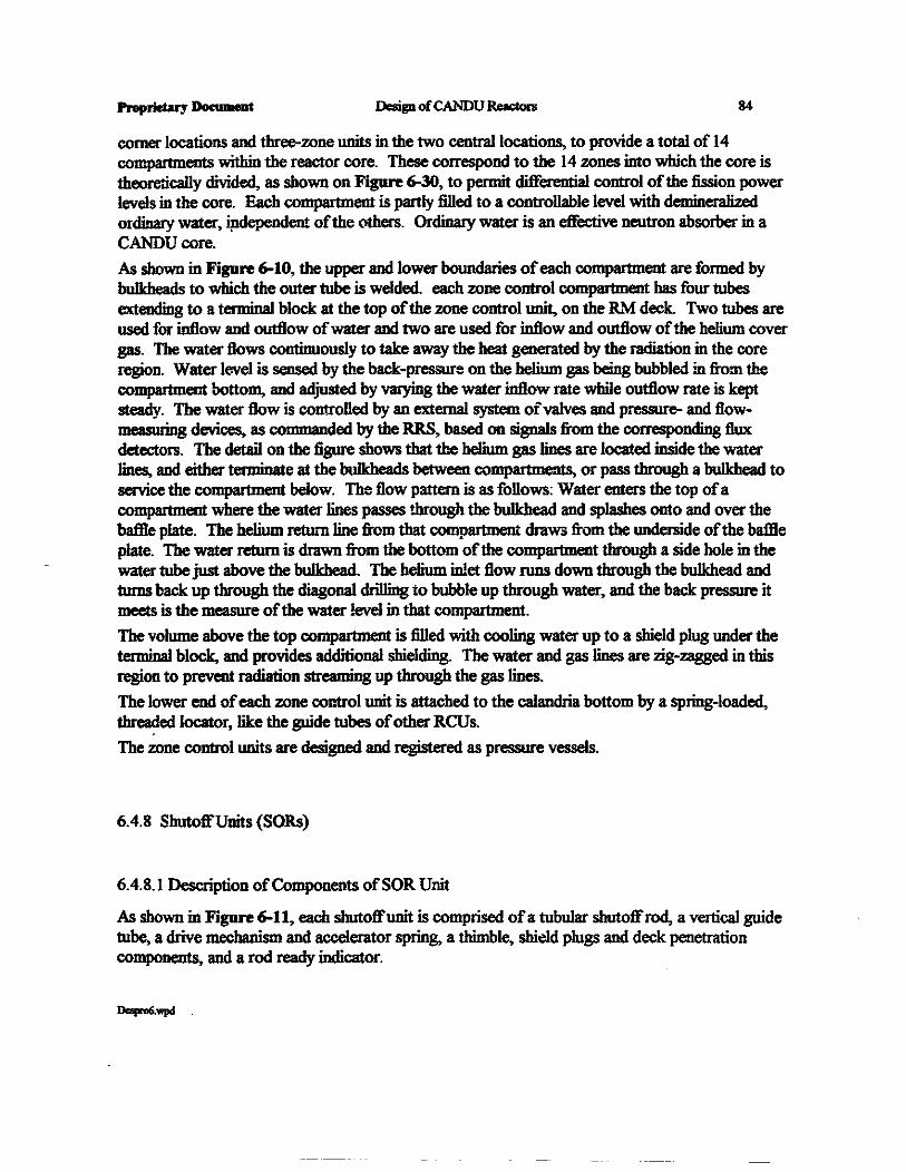
comer locations and three-zone units in the two centra1locations, to provide a total of 14compartments within the reactor core. These correspond to the 14 zones into which the core istheoretically divided, as shown on Figure 6-30, to permit differential control ofthe fission powerlevels in the core. Each compartment is partly filled to a controllable level with demineralizedordinaIy water, ipdependent ofthe others. Ordinary water is an effective neutron absorber in aCANDUcore.
As shown in Figure 6-10, the upper and lower boundaries ofeach compartment are formed bybulkheads to which the outer tube is welded. each zone control compartment has four tubesextending to a terminal block at the top ofthe zone control unit, on the R,.\{ deck. Two tubes areused for inflow and outflow ofwater and two are used for inflow and outflow ofthe helium covergas. The water flows continuously to take away the heat generated by the radiation in the coreregion. Water level is sensed by the back-pressure on the helium gas being bubbled in from thecompartment bottom, and adjusted by VlII}'ing the water inflow rate while outflow rate is keptsteady. The water flow is controlled by an external system ofvalves and pressure- and flowmeasuring devices. as commanded by the RRS, based on signals from the corresponding fluxdetectors. The detail on the figure shows that the helium gas lines are located inside the waterlines, and either terminate at the bulkheads between compartments, or pass through a bulkhead toservice the compartment below. The flow pattern is as follows: Water enters the top ofacompartment where the water lines passes through the bulkhead and splashes onto and over theba1Be plate. The helium retulllline from that compartment draws from the underside ofthe ba1Deplate. The water return is drawn from the bottom ofthe compartment through a side hole in thewater tube just above the bulkhead. The helium inlet flow runs down through the bulkhead andturns back up through the diagonal driI1ing to bubble up through water, and the back pressure itmeets is the measure ofthe water level in that compartment.
The volume above the top compartment is filled with cooling water up to a shield plug under theterminal block, and provides additional shielding. The water and gas lines are zig-zagged in thisregion to prevent radiation streaming up through the gas lines.
The lower end ofeach zone control unit is attached to the calandria bottom by a spring-loaded,threaded locator, like the guide tubes ofother RCUs.
The zone control units are designed and registered as pressure vessels.
6.4.8 ShutoffUnits (SORs)
6.4.8.1 Description ofComponents ofSOR Unit
As shown in Figure 6-11, each shutoffunit is comprised ofa tubular shutoffrod, a vertical guidetube, a drive mechanism and accelerator spring, a thimble, shield plugs and deck penetrationcomponents, and a rod ready indicator.

DesigD ofCANDUR-.. 85
Each shutoffrod (SOR) is suspended from stainless steel wire rope that is wound onto the sheaveofits drive mechanism.The slutoffrod is a tubular lamination, comprised ofinner and outer stainless steel sheath tubes,enclosing a thin cadmium layer. Its construction is shown on Figure 6-31. The sheath tubes arewelded closed ateach end, and welded to an end ring at the bottom and the stainless steel pushrod at the top. The supporting cable is attached to the push rod by means ofa special nut, whichtraps a ball swaged onto the cable end. The push rod also carries a collar part way up, on whichthe compressed accelerator spring locates through a travelling spacer ring, when the SOR is in thewithdrawn (POised) position.
The accelerator spting is enclosed in a casing attached to the underside ofthe shield plug. Whenthe SOR is poised, it compresses the spring. When the SOR is released, the spring providesenergy supplementing gravity, to accelerate the SOR into the core. The spring acts only over theinitial metre or so oftravel, then is arrested by the bottom traveIiing spacer nesting on the bottomcifthe casing
The drive mechanism is an electric motor-powered winch which includes an electro-magneticclutch to couple the sheave shaft to the motor gear train. The mechanism is bolted and sealed onthe top ofthe thimble directly above the rea...--tivity mechanism deck. Its components areschematically shown on the detail of Figure 6-11.
6.4.8.2 Operation ofSOR
De-energization ofthe clutch by a trip on the SDS I circuit permits the sheave to rotate freely,under the torque due to gravity and the accelerator spring acting on the rod. The sheave shaft ispermanently coupled to the damper through the position limiter device. This device is a series of"dog-plates" on which a protruding lug connects to a similar lug on the next plate. after 0.875revolutions. There are eleven such plates, so they all become connected after 9.625 revolutions ofthe shaft. The last plate connects to a damper vane which will contact a stop on the housing endplate after it travels 0.875 revolutions, making a total shaft travel of 10.5 revolutions. Thisprovides a positive down stop position at the end oftravel. When the SOR is withdrawn, all ofthe plates rotate back to their originaI positions, and the damper connects to the up stop on thehousing end plate. The damper vane is enclosed in a sealed, cylindrical, oil-filled cavity which hasa small by-pass groove in the end plate. This acts as a rotary hydraulic damper to resist therotation ofthe shaft as the damper vane makes its rotation at the end oftravel, and forces the oilin front ofit through the by-pass into the space behind it. This acts to arrest the momentum ofthefalling SOR to bring it to a smooth stop at the end ofits travel.
When the clutch is energized by clearance ofthe trip signal, the rod is raised by its motor. Thevertical position ofthe rod is measured by a rotary electrical potentiometer on its sheave shaft.When the rod is driven up or down, the motion is stopped by the motor being shut offby thecontrol system via the position sensing circuit run from the potentiometer output, before the endofmechanical trave1 is reached.
Proprietary DlDo__Dt Design ofCANDUR-.. 86
A second position sensor, the "rod ready" indicator, directly monitors the presence of the rod inthe up position, to verify it is "ready" for use. It consists ofa set ofmagnetic switches mountedin a well in the shield plug, actuated by a permanent magnet mounted inside the top ofthe SORpush rod.
To meet the CANDU safety philosophy ofseparating safety and regulating functions, the clutchand "rod ready" indicator are part ofsafety circuits only. The withdrawal motor is part oftheregulating system, and this mechanical configuration guarantees that it cannot withdraw the roduntil the safety trip holding the clutch de-energized is cleared.
6.4.8.3 SORPerfurmance
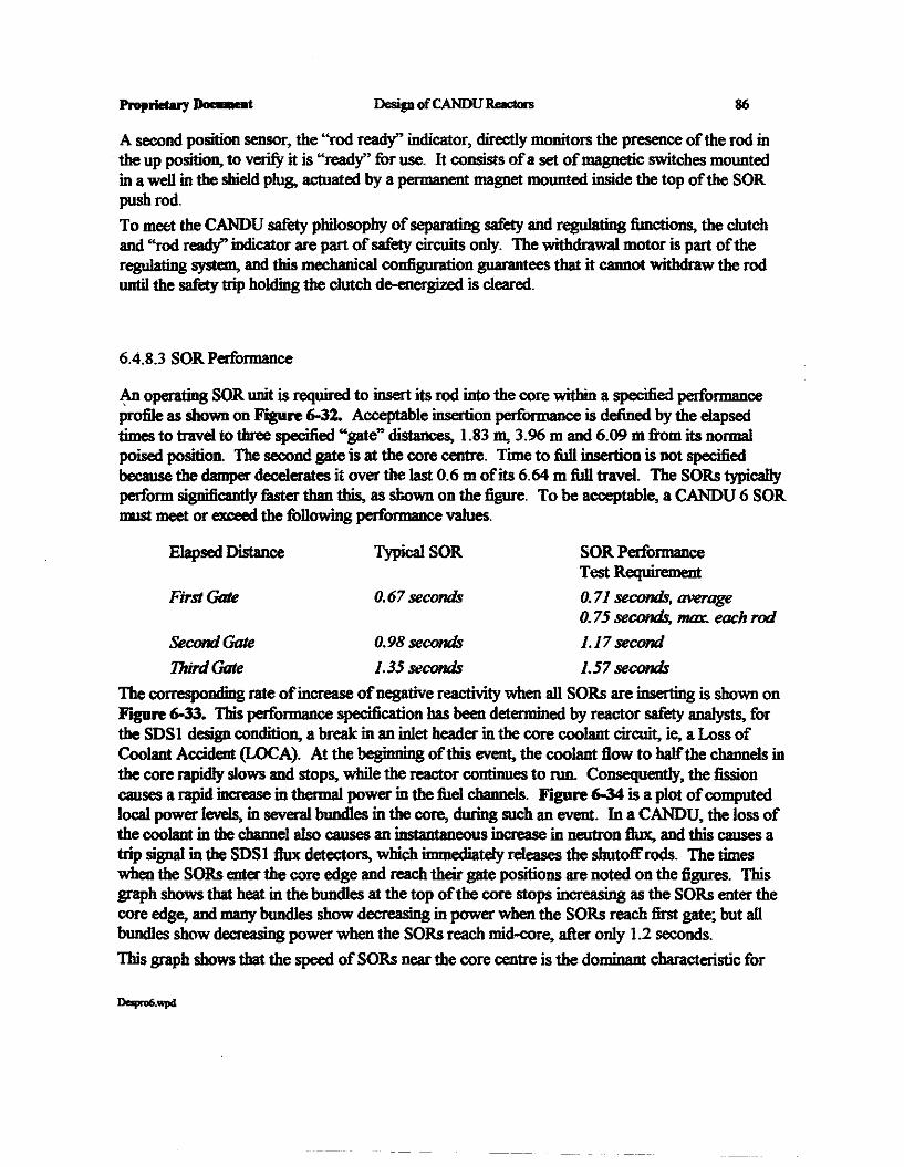
An operating SOR unit is required to insert its rod into the core within a specified performanceProfile as shown on Figure 6-32. Acceptable insertion performance is defined by the elapsedtimes to travel to three specified "gate" distances, 1.83 m, 3.96 m and 6.09 m from its normalpoised position. The second gate is at the core centre. rune to full insertion is not specifiedbecause the cIampeI" dece1erates it over the last 0.6 m ofits 6.64 m full travel. The SORs typicallyperform significant1y filst:er than this, as shown on the figure. To be acceptable, a CANDU 6 SORmust meet or exceed the following performance values.
Elapsed Distance Typical SOR SOR performanceTest Requirement
First Gate 0.67 seconds 0.71 seconds, average0.75 seconds, max. each rod
Second Gate 0.98 seconds J.l7 second
Third Gate 1.35 seconds 1.57 seconds
The corresponding rate of increase ofnegative reactivity when all SORs are inserting is shown onYJglIre 6-33. This performance specification has been determined by reactor safety analysts, forthe SDS1 design condition, a break in an inlet header in the core coolant circuit, ie, a Loss ofCoolant Accident (LOCA). At the beginning ofthis event, the coolant flow to halfthe channels inthe core rapidly slows and stops, while the reactor continues to run. Consequent1y, the fissioncauses a rapid increase in thermal power in the fuel channels. Figure 6-34 is a plot ofcomputedlocal power levels, in several bundles in the core, during such an event. In a CANDU, the loss ofthe coolant in the channel also causes an instantaneous increase in neutron flux, and this causes atrip signal in the SDS1 flux detectors, which immediately re1eases the shutoff rods. The timeswhen the SORs enter the core edge and reach their gate positions are noted on the figures. Thisgraph shows that heat in the bundles at the top ofthe core stops increasing as the SORs enter thecore edge, and many bundles show decreasing in power when the SORs reach first gate; but allbundles show decreasing power when the SORs reach mid-core, after only 1.2 seconds.
This graph shows that the speed ofSORs near the core centre is the dominant characteristic for
Dapro6.wpcI

DesipofCANDU ReIcIcrs
the system ofSORs. However, once the fission power has been shutdown, there is a secondphenomenon to deal with as well Secondary decay processes continue and generate delatedneutron flux, which causes secondary heating. The system ofSORs must have sufficient depth ofdistn1luted negative reactivity to suppress these reactions, and this is independant ofthe speed ofshutting down. ,Following clearance ofthe abnonnal reactor condition causing the trip, the trip circuit can be resetby the operator, and he can withdraw the SORs. The SORs are withdrawn in groups, at a fixedspeed, each being re-poised ("armed") in 150 seconds. This slow removal is necessary to avoidthe ion chambers causing a re-trip, due to an excessive rate ofchange ofneutron flux.
CANDU practice is to withdraw ail the SORs as soon as a trip is removed and to keep thempoised whenever there is no trip applied. For example, they remain poised while service tasks areto be done elsewhere in the plant before re-starting, or throughout all plant maintenance outages.This ensures that the negative reactivity ofthe SORs is available to be inserted should there be anUnexpected rise in core reactivity during the shutdown, eg, an inadvertent removal ofdi."50lvedboron from the moderator, say, through test nmning ofthe pumps on the ion exchanger circuit.The SORs cannot be made unavailable unless the reactor is first placed in a "guaranteed"shutdown state, ie, the moderator poisoned by boron and the boron circuit valved out and locked;or the moderator drained and locked out.
Because ofthe build-up ofXenon in the fuel following a shutdown, and the total amount ofreactivity change that the RCUs can collectively provide, a CANDU reactor must re-startedwithin 20 minutes to avoid a poison out. ~starting takes about 10 minutes, by removal ofADJs, MCAs and IZCs. This means that ifthe shutdown had been caused by a spurious trip, (ie,a "false alarmj, and there is no real reactor abnormality, the reactor can be returned to full powerifthe situation is properly identified within 10 minutes. Ifthe restart is not started by then, thereactor poisons out, and the plant must stay shutdown for 40 hours, until the Xenon decays to asufficiently low level.
As part ofa special safety system, the shutoffunit must be qualified to insert while enduring botha LOCA event and a DBE seismic event, although not simultaneously; and it must also be able toinsert. immediately following either event. However, the ability to withdraw is not a requirementduring or after those events. Accordingly, insertion qualification tests are performed on acomplete SOR unit under both simulated LOCA and earthquake conditions. Since its safetysystem function is not dependant on the enclosed pressure during those events, it remains a class 3item, as an extension to the calandria, enclosing the moderator. Aecordingly, its pressureboundary components are designed and pressure tested in the same way as other RCUs, but itsmechanical performance must be demonstrated by testing. Note that a major LOCA event, suchas a PHT header break, applies external pressure and temperature on the SOR, but the SOR willhave already inserted to shut down the reactor due to a PHT proces; trip, well before theseconditions act on the outside ofits housing. The most critical LOCAs for SOR insertionperformance are smaller LOCAs such as a feeder break., where hot conditions may prevail forseveral minutes, or even hours, before the trip occurs.

88
6.4.8.4 Kinematics and Dynamics ofSOR Insertion Process
When SOR performance is measured in testing, the SO unit's own potentiometer signal is firstcalibrated against physical height measurements ofthe element being lowered slowly. Anelectronic chart recording then provides an accurate record ofposition versus time, with timemeasured from the point ofinterruption ofclutch power. Marhematically, the shutoffunit issimply represented as a mass which accelerates downwards under the influence ofa number ofvarying forces. The inertia ofthe rotating sheave and ofthe spring and the cable act as addedparasitic masses equivalent to about 1/3 the weight ofthe standard rod. The forces acting aregravity plus the decreasing initial spring force, less the initial drag ofthe gradually releasing clutchplates and increasing hydrauJic drag and buoyancy as the rod inserts into the moderator. Thisresults in an approximately parabolic acceleration to about the 2 m mark., after which the forcesvirtually reach equilibrium and it continues at essentially constant speed. See the graph in YJgIlft6-32. An acceptable CANDU 6 SOR bas a briefdelay ofabol..t 0.14 seconds, then acceleratesand travels to about 1.87 m in the first 0.75 seconds, then continues at essentia1Iy constantvelocity to reach 6.14 m at 1.57 seconds and then is decelerated in the last 0.6 m travel. Actualrods are usually filster, by typically 0.075 seconds. The initial 0.14 second delay is due to excesscapacity ofthe clutch compared to the torque applied by the spring and the weight ofthe rod.This is a margin to preclude slippage ofthe rod offthe poised position. When released, theelectro-magnetic field clamping the filction plates bas to decay until it drops to equal the value ofthe applied torque, where it can start to slip. Even then, the diffetenc:e between the clutch'sinstantaneous capacity and the torque applied is only gradually increasing, to cause increasingacceleration as the field continues decaying.
6.4.8.5 performance Verification In Service for SOR
In..service, shutoffunit insertion performance is measured by recording the drive's potentiometersignal against time elapsed after the electric power to the clutch is opened. Each SOR is tested onpowerby a "partial drop" approximately once a month, to confirm its availability and the properinitiation ofits release. This is not a full insertion, but a momentary opening and re-closing ofitsrelease device, for a carefully controlled standard time interval. The rod inserts only about 10"..4ofits stroke, i.e., to just reach the vicinity ofthe first row ofcalandria tubes. The actual distancetravelled is not ofconsequence, since it is the consistency ofthe measured distance compared toits previous history that is important. The small perturbation in the core is also monitored on theflux detectors. For rods near the centre, some upper detectors will indicate a change ofup to afew percent oftheir normal reading. A deviation ofmore than 15% from its normal test results isgrounds for declaring that SOR unavailable for service, subject to closer examination at the nextshutdown.
6.4.9 Liquid Injection Shutdown Units (LIS)
The in-reactor portion ofeach liquid injection shutdown unit consists ofan in-core injection

DosipofCANDUa- 89
nozzle tube, an injection pipe, a thimble and a caJandria vault wall penetration assembly. Thesecomponents are shown in Figure 6-12. The remainder ofthe liquid injection s1mtdown systemconsists ofinjection piping and a liquid poison storage tank for each nozzle tube, a commonpressurized helium supply tank, a set common oftriplicated, fast-acting release valves arranged ina series! parallel~ a poison mixing tank, and a drain tank. A schematic diagram ofthe USSis shown in Figure 6-13.
The moderator in the caIandria fills the nozzle tubes and the injection piping, all the way back tobottom ofthe poison tanks. The liquid in the poison is moderator water which bas 2000 parts permillion ofGadolinium Nrtrate dissolved in it, which is a strong neutron absorber. There is nophysical boundary between the poisoned fluid and the pure moderator in the pipe circuit. Theelevation ofthe liquid poison tanks is set such that the free surface ofthe fluid inside is at theelevation ofthe moderator in the ca1andria. A small pipe connects the top volume in the tanks tothe calandria covei gas system, to ensure a pressure balance. Inside each tank, a polyethylene ballfloats on the fluid surface. When a tank d."lIins out the ball drops down and seats on the pipe exitat the bottom, to seal it off.
The injection nozzles are machined Zircaloy extrusions, screwed into the stainless steel injectiontubes at their inlet ends. See Figure 6-35. They are secured by a bayonet at their iocators (mplace ofthe coupler screw ofother RCUs) on the opposite side ofthe calandria Each nozzle ispelforatedbyrows ofsma11nozzle holes spacedand oriented to optimize poison dispersal in themoderator. It is tensioned by using the light water bellows as a spriBg.
The liquid poison storage tanks. quick-opening valves and the dedicated high pressure heliumstorage tank are mounted on the D side shield wall attached to the vau1t wall. Figure 6-36 showsthis arrangement. The routing ofthe LIS piping from the tanks is designed so as to ensure clearaccess to the housings for the other horizontal RCUs, including clear space at each site for atemponuy shielded nose piece for the fiask in the event ofa removal.
When a trip signal is initiated in the SDS2 circuit, the solenoid-operated quick opening valvesopen to admit the high pressure helium to the top ofthe poison tanks, where its pressure causesthe fluid to accelerate through the injection pipes and nozzle tubes, to inject through the nozzleholes into the moderator. The plumes ofinjected fluid trave1 rapidly into the entire core region,and to quickly s1mt down the fission process. The fluid rapidly disperses and mixes thoroughly.Figure 6-37 shows the increase ofnegative reacfrYity. Comparing this figure to Figure 6-33, forthe SOR, it appears that the SOR reaches its full reactivity umch faster than the USS (1.6 secondvs 15), but in fiIct, the LISS final "deptIt" is-very muchgreater, and it reaches the necessary -50mk after only 1 second, while the SOR takes 1.6 seconds. Since the fluid bas completely mixedwith the bulk ofthe moderator throughout its entire circuit, the LIS cannot be re-poised quickly,and a LISS firing inevitably causes a Xenon poison out for 40 hours. The gadOIiniU41 nitratesolution is removed by pumping all the moderator through an ion-exchanger.
The strength ofthe gadolinium nitrate solution is assured by monitoring it by an electricalconductivity probe in the injection pipe close to the core. As there is no physical barrier between

Design ofCANDU RacIors 90
the moderator in the calandria and the poisoned fluid in the tank, the two fluids mix slowlythrough diffusion. Ifpoison is detected at the probe, the fluid it is drained from the tank andpiping and a new solution mixed and inserted in the tank. This can be done while on power, onone USS circuit at a time, by va\ving that unit out.
The availability 8nd proper operation ofthe LISS actuating valves is checked periodically inservice, by closing sections ofthe triplicated, series/para\\e1~ this permits closing andarnJating part of the va\ve set while the other part remains available for service.
The insertion offluid through the injection piping and injection nozzles cannot be tested onpower, because the poison from even one nozzle would cause an unacceptable perturbation fluxdistribution in the core. Furthermore, the LIS units cannot be tested one at a time because theyhave a common helium supply and a common set ofactuation valves. Consequently, the LISsystem is tested only at a planned plant shutdown. When the LIS system is tested, all units are8ctuated at once, and the system performance (mcluding that ofthe trip circuitly) is verified bymeasuring the resctivity run-down on the flux detectors. Verification that each unit released isindicated by observing proper run-down ofsignal from appropriate nearby detectors, andaccepflIbility oftotal reactivity is determined from integrating the rates from all detectors
As a safety system, the liquid injection shutdown unit is qualified for both seismic and LOCAenviromnentaI conditions, as weD as being designed as a pressure-retain system. As a safetysystem relying on pressure to function, its injection circuit is designated a class I system. Becauseits operating pressure is the highest pressure it can ever be subjected to, that is also its designpressure, ie, the LOCA which causes its actuation is a Level C condition for the reactor, but it is alevel A service condition for the LIS nozzle.
6.5 Manufacturing Aspects
All in-core RCU components are made from Zircaloy-2 or -4, except the absorber elements andthe fIiJx detector sensing elements. The large guide tubes are made from perforated strip, formedand seam welded, with end fittings welded on, then annealed, straightened and stress relieved.SmaDer tubu\ar members are ofpilgered seamless tube.
Out-of-core members are ofseamless stainless steel tube, or machined from bar, generally ofAlSItype 304L. Housings are generally ofcast stainless steel or machined from bar stock.
The in-core components ofthe flux detector assembly, other than the detectors themselves, arefabricated from seamless Zircaloy tubing which extends up to the connector housing, where it iswelded or clamped to Zircaloy bolting flanges. The housing is machined from stainless steel barstock. The central shield plug and individual weD shield plugs are aluminium extruded rod andwire, respectively. The individual detectors are proprietary items, drawn and compacted frominitiaI\y loose assemblies ofemitter core wires or lead wires, Inconel sheath tubes and beads ofceramic insulation.

Design ofCANDU ReacIon 91
The ion chamber housing shell is a welded stainless steel fabrication that is filled with cast, reactorgrade lead alloyed with small amounts ofbismuth and tin. Brackets welded to the calandria shellto support each ion chamber housing are stainless steel. The access tube assembly is a stainlesssteel fabrication that is welded to the housing and is connected to the vault wall via the stainlesssteel Oellows. T\1e ion chamber instruments are enclosed in aluminium sleeves and shielded andsupported by high purity aluminium shield plugs.
The adjuster and shutoffdrive mechanisms consist ofstainless steel housings with nodular castiron used for some non-pressure retaining sections. The intemal mechanical components ofthemechanisms are mostly ofClIJbon, alloy or stainless steel. The proprietary shaft seal has a Stellitebellows with carbon and ceramic fiIces. This seal and the drive motor are shared in common byADJ, MCA and SOR drive mechanisms.
The liquid zone control assemblies are manufactured from Zircaloy tubing and welded to Zircaloybulkheads separating the compartments. Internal tubes are given small zig-zag bends so they willtie sprung against the outer tube when they are inserted. Near the top ofthe unit there are astainless steel shield plug and a Zircaloy flanged terminal block. The bottom ofthe assembly isfitted with a Zircaloy locator coupling which is tensioned by an Inconel spring.
The construction ofthe shutoffrod involves the drawing and sizing ofa cadmium sheet betweentwo annealed stainless steel tubes so that the cadmium is completely enclosed and sealed when theeods are welded closed. The stainless steel end rings, support rod and spider ring are then weldedto these composite cadmium and stainiess steel tubes.
The US uyection nozzle is fabricated from a Zircaloy extruded tube, machined to remove surplusmaterial. The end pieces are machined from Zircaloy bar stock and welded to the tube. TheZircaloy surfaces which slide in the bearing bores at the ca1andria penetration nozzles are treatedby an AECL proprietary process to generate a very hard, durable zirconium oxide surfiIce layer.The uyection tube is made ofstainless steel pipe, with bearing sections made from machined bar,welded to the pipe. The nozzle tube and injection pipe are joined by a screw thread.
The RM deck is a closed, welded carbon steel fabrication with pre-machined penetration insertsand intemal webs welded in after the main box is completely welded and machined. Concretefil6ng is poured in place after the structure's support webs have been welded to the vaultembedments. The gap above these webs, between the sides ofthe deck box and the vault roofconcrete. is filled with soft Styrofoam to provide an elastic filler, and the joint above closed withthiokol rubber caulking.
6.6 Analysis, Qualification Testing and Production Acceptance Testing
Only RCUs which perform functions for either ofthe two shutdown systems need to beenvironmentally and seismically qualified. Other RCUs, for regulating system service, need to bequalified for those events only to a limited extent, in two respects:
(a) for any accident, it must be assured that they will not fail in such a way as to cause an

Proprietary Do ........t Design ofCANDU Reactors 92
increase ofreactivity (ie, they must either fall into the core or remain in place, ifalready in)
(b) it must be assured that, for any accident, they will not fail in such a way which wouldinhibit proper operation ofa nearby safety system item.
This means that flux detector assemblies, ion chamber instruments and the two shutdown units aresubjected to testing to demonstrate they will perform their safety functions dwing and afterseismic excitation and then during and after exposure to the temperature and pressure cycles ofsevere accidents. The methodology oftesting of these items is further discllssed in the followingsections.
All components for all RCUs are subjected to stress and seismic analyses to demonstrate theymeet requirements ofappropriate standards for design for mechanical components and/or pressureretaining items, and that they retain their structural and pressure boundary integrity under allnormal and extreme conditions. All pressure retaining items are pressure tested to the requiredmargin above their design pressures, as sub-assemblies during 1lIlI!lUfiIcture and/or at installationafter their final closure joints are made.
6.6.1 Struct....ral items
For all RCUs, the thimble assemblies are pressure tested after installation, so as to include thewelds to the caJandria nozzles; for horizontal devices, this will include their bellows. The sealed,bolted joints where the mechanisms seat on the thimble are pressure and leak tested as part oftheleak test ofthe completed calandria assembly.
6.6.2 The Flux Detector Unit
The flux detector unit design was qualified by seismic performance testing and environmentaltesting, on irradiated! aged specimens which included the detector elements. They were tested tosimulated Design Basis Earthquake (OBE) response excitation levels and for LOCA-LOECC andsmall LOCA conditions to confirm both structural and electrical durability and operability. Thiswas in addition to normal stress and seismic analyses performed to demonstrate conformance tomechanical and pressure vessel design standards.
6.6.2.1 Seismic Testing ofthe Flux Detector Unit
Because it is a very long and flimsy assembly, seismic testing ofa full scale, full length assemblywas impossible, especially considering that the housing and the in-core portion are subjected tototally different conditions. Instead, a complete housing assembly (with internal wiring) and arepresenta#ve, 2-metre length ofthe in-core assembly were separately tested.
For the housing specimen, analysis demonstrated that there were no resonant responses in thehousing itsel( for the prevai1ing input FRS at the RM deck level. (See Section 4, also Figure 410, on vibration and seismic behaviour.) Therefore, the specimen was mounted on a dummysection ofthimble top and the corresponding unamplifiedfloor motion excitation for the vault topwas applied, (not the FRS response acceleration levels). Accordingly, this would generateresponses ofinternal items, like the connectors and wiring, ifthey had resonant frequencies.
Dospo6.wpd
Design ofCANDU~ 93
None were found. During this test, the electrical resistance and circuit continuity ofthe detectorleads and connectors was monitored continuously. Flux detector performance relies onmaintaining insulation resistance above 10" ohms. No inconsistencies were found.
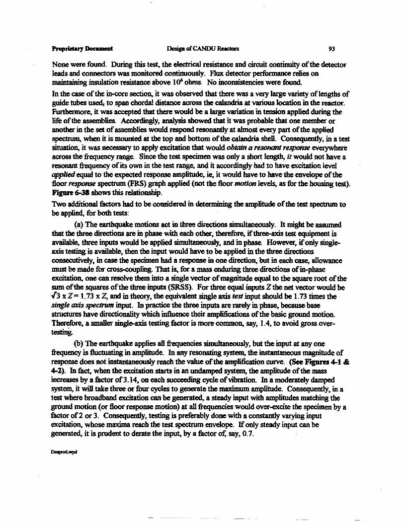
In the case ofthe in-core section, it was observed that there was a very large variety oflengtbs ofguide tubes used. to span chordal distance across the caIandria at various location in the reactor.Furthermore, it was accepted that there would be a large variation in tension applied during thelife ofthe assemblies. Accordingly, ana1ysis showed that it was probable that one member oranother in the set ofassemblies would respond resonantly at almost every part ofthe appliedspectnmJ, when it is mounted at the top and bottom ofthe calandria shell. Consequently, in a testsituation, it was lIecessary to apply excitation that would obtain Q resonant response everywhereacross the frequency range. Since the test specimen was only a short length, it would not have aresonant frequency ofits own in the test range, and it accordingly bad to have excitation levelapplied equal to the expected response amplitude, ie, it would have to have the envelope ofthefloor response spectrum (FRS) graph applied (not the floor motion levels, as for the housing test).Figure 6-38 shows this relationship.
Two additional filctors bad to be considered in detet I !lining the amplitude ofthe test spectrum tobe applied, for both tests:
(a) The earthquake motions act in three directions sinmltaneousIy. It might be assumedthat the three directions are in phase with each other, therefore, iftbree-axis test equipment isavailable, three inputs would be applied simultaneously, and in phase. However, ifonly singleaxis testing is available, then the input would have to be applied in the three directionsconsecutively, in case the specimen bad a response in one direction, but in each case, allowancemust be made for cross-coupling. That is, for a mass enduring three directions ofin-phaseexcitation, one can resolve them into a single vector ofmagnitude equal to the square root ofthesum ofthe squares ofthe three inputs (SRSS). For three equal inputs Z the net vector would be,[3 x Z = 1.73 x Z, and in theory, the equivalent single axis test input should be 1.73 times thesingle axis spectrum input. In practice the three inputs are rare1y in phase, because basestructures have directionality which influence their amplifications ofthe basic ground motion.Therefore, a smaller single-axis testing 1iIctor is more common, say, 1.4, to avoid gross overtestmg.
(b) The earthquake applies all frequencies simultaneously, but the input at any onefrequency is fluctuating in amplitude. In any resonating system, the instantlIneous magnitude ofresponse does not instantaneously reach the value ofthe amplification curve. (See Fignres 4-1 &:4-2). In filet, when the excitation starts in an undamped system, the amplitude ofthe massincreases by a filctor of3.14, on each succeeding cycle ofvibration. In a moderately dampedsystem, it will take three or four cycles to generate the maximum amplitude. Consequently, in atest where broadband excitation can be generated, a steady input with amplitudes matching theground motion (or floor response motion) at all frequencies would over-excite the specimen by afilctor of2 or 3. Consequently, testing is preferably done with a constantly varying inputexcitation, whose maxima reach the test spectrum envelope. Ifonly steady input can begenerated, it is prudent to derate the input, by a filctor of; say, 0.7.
DcsignofCANDU~ 94
On the other hand, ifbroadband excitation cannot be generated, and testing is done by sweepingthrough the frequency range, only a single frequency is applied at any ir.stant. In this case, thepotential for coupling two inputs at close frequencies is missed, and the system is under tested.(See the graphs on YJgUft 4-8). Ifsingle frequency sweep testing DDlst be done, wherever tworesponses are~ at close frequencies, it is prudent to increase the input amplitude at thosefrequencies by a tilctor of, say, ].4.
In any given test, the above tilctors DDJst be considered, and the product ofthose varioussuggested tilctors would be applied.
During this test, as on the housing test, the electrical resistance and circuit continuity ofthedetector leads was monitored continuously. No inconsistencies were found.
6.6.2.2 Environmenial Qualification Testing ofthe Flux Detector Unit
Only the housing needs to be LOCA qualified for the flux detector unit as the LOCA conditionsdo not act inside the calandria. The housing assemb1y used for seismic testing was mounted andsealed to a dummy thimble top and installed in a test chamber and a simulated LOCA was applied.No inconsistencies were found, although some acceptable decrease was observed in insulationresistance in the connnercial connectors, which recovered upon cooling. No leaks were observed.
6.6.2.3 Production Tests on Flux Detector Units
Each flux detector assembly is leak tested and pressure tested at manufacture. The assemblypressure boundaIy is hydraulically pressure tested in JIIlIIIIIfilctu. The joints to the thimble arechecked for leak-tigbtness during functional commissioning ofthose systems. The electricalresistance and capacitance ofthe individual detectors are also checked at both mamdilcture and atirlstaJlatioo. The location and operability ofeach detector, and the correctness ofcircuitconnections is finally confirmed by low power reactivity experiments during commissioning.
6.6.3 Ion Chamber Unit
The ion chamber unit, including the housing, access tubes, penetrations and internals is qualifiedfor both pressure vessel design and seismic response by analysis. Seismic and environmentalqualification ofthe instruments and its electrical components and connectors is assured by their1I18IIIIfilctur.
The caJandria external pressure test provides the pressure test for the ion chamber housing, accesstubes and bellows. Mechanical operation ofthe shutter mechanism is checked during mamdilctureand after instaDation. The location and operability ofeach instrument, and the correctness ofcircuit connections is finaiiy confirmed by low power reactivity experiments duringcommissioning.
~.wpd

Proprietary~
6.6.4 ShutoffUnit
Design ofCANDUR-mrs 95
6.6.4.1 perfonnance Qualification Testing
The development testing for perfonnance ofthe CANDU 6 unit was an extension ofthat for theBruce A unit, or'wbich it is virtually a copy. For the Bruce design, a prototype unit built to fullproduction standards was installed in a full scale test rig in a water-filled tank, and extensivelytested to determine its basic insertion perfol1Jlllllce, and to prove efficacy ofthe basiccomponentry, including its bearings, seals, clutch, gearing, etc, with especial attention to therotary hydraulic damper which decelerates the rod at the end oftravel. Other tests ensured itsinseDsitivity to likely varU;.tion.~ in conditions, such as temperature or level ofmoderator, etc.ContimJous cycling tests ran for 3000 cycles, to demonstrate its durability without maintenance oradjustment; this is many times the lifetime service requirement. These tests were done usingordinary water at room temperature, but computer modelling, verified by subsequent in-reactortests, showed that the slight change in density is offilet by a similar slight change in viscosity, toobtain a virtually identical performance. Most ofthese tests have been repeated on CANDU 6units and some ofthem again on actual reactor installations.
6.6.4.2 Seismic Testing afthe SOR unit
Seismic performance testing was done on complete sbutoffunits, to Design Basis Earthquake(DBE) response excitation levels. The seismic test rig was comprised ofa large vertical tankrepresentative1 supporting the SO unit at the calmdria top and bottom and at the RM deck. SeeFigure 6-39. It bad short lengths ofcalandria tube alongside the guide tube in the in-coresection, to accurately simulate in-core pressure transients caused by water displaced by aninserting rod. Electro-magnetic exciters were mounted horizontally at the top and bottom oftheguide tube, where it attaches to the caIandria; another was at the mechanism, where it mounts inthe RM deck. They were excited by time history si8Dals simulating a real earthquake, amplifiedand damped to represent the local structural response. Instruments measured responseaccelerations and displacements on key components. Other tests were done widl discrete, steadyfrequency inputs applied, swept over the entire frequency range, to determine componentcharacteristics.
The seismic qualification testing ofthe SOR was done in two parts. FJrst, the mecbllnism alonewas subjected to excitation as the rod was repeatedly released. The applied test excitationincluded a 1.65 times factor on the design spectta values to conservatively account for testingcharacteristics. The mechanism was shown to be entirely free ofresonances and insertionperformance was identical for all tests.

96
The second phase was done on a complete, instrumented SOR unit installed on the full sizedseismic test rig shown in the figure. It was excited by electronically controlled hydraulic actuatorsat the RM deck and at the top and bottom ofthe immersed guide tube. Time histories sinnJlatingsevera1 fiunilies ofactua1 earthquakes were applied, with varied amplification to represent variedseverity ofearthquake. These are equivalent to about 0.3 g ground motion input at the reactorbuildiDg base, well above any current CM'DU site requirements. There were also supplementaryexcitation tests on the individual guide tubes, thimbles and the absorber, to determine theirindividual resonant frequencies. Figure 6-40 shows a typical recording ofthe key parameters forthe SOR dropping wbile the simulato:d earthquake is being applied.
These tests demoDSlrated that the unit inserts within specified times during and after application ofany one ofthese conditions. The seismic tests showed that the shutoffinsertion is slowed by asma\! amount oftime, directly proportionate to the response accelenltion ofthe in-core guidetube, reaching only 0.04 seconds for 0.4 g input ground motion. For environmental accidentconditions, the stainJess steel housing ensures the extreme tempeIature and pressure havenegligible effect on internal components in the briefexposure time before the rod is dropped;there is no measurable retardation.
6.6.4.3 Environmental Qualification ofthe SOR unit
The LOCA test rig comprised a steam chamber enclosing the mechanism, and an adjacent waterfilled tower containing the rod and guide tube. Thermocouples monitored appropriate points inthe mer.hanism The rod was repeatedly dropped at varied time interva1s following the chamberbeing filled with steam, at programmed temperature and pressure.
6.6.5 US Unit
The pattern ofthe liquid poison's distribution into the moderator fluid, and its rate ofgrowth wasdetermined by extensive underwater testing. The influence ofvaried nozzle hole sizes,distributions. attitudes, tube positions and also pressures was learned from extensive testing and acomputer code was developed, from which designs can be optimimd. It is also used to predictperformance for new reactor designs, where a larger reactor size requires a longer nozzle tube,effecting insertion time. Parameters can also be varied to study means to change insertion speed,or its initial delay.
6.6.6)\Jfjllster
The adjuster is a relatively simple device, and its development testing was limited to endurancequa1ification for the componems, particularly the high ratio, single pass gearing. The assemblypressure boundary is hydraulically pressure tested in manufacture. The joints to the thimbles are
DoII>n>6.wpd
Proprietary Duc:a&eut Design ofCANDU Reactors 97
checked for leak-tightness during functional commissioning ofthose systems.
6.6.7lZC
The liquid zone control has no moving parts, and no qualification or functional testing is required.The CANDU 6 design is only slightly changed from the Pickering A unit from which it hasevolved. Component durability was proven on those original prototypes.
The assembly pressure boundaIy is hydraulically pressure tested in manufilcture. The joints to thewater and gas systems are checked for leak-tightness and correctness ofconnection duringfunctional commissioning ofthose systems.